sanyo absorption chiller/heater ccn...
TRANSCRIPT

Sanyo Absorption Chiller/Heater CCN Gateway
Overview and Configuration Manual
2
This document is the property of Carrier Corporation and is delivered on the express condition that it is not to be disclosed, reproduced in whole or in part, or used for manufacture by anyone other than Carrier Corporation without its written consent, and that no right is granted to disclose or so use any information contained in said document. Carrier reserves the right to change or modify the information or product described without prior notice and without incurring any liability. © 2008, Carrier Corporation

3
Contents Contents .......................................................................................... 3 Overview .......................................................................................... 7
About this manual ............................................................................................. 7 Introduction ....................................................................................................... 7
System Overview............................................................................. 9 Sanyo Gateway Hardware .............................................................................. 12
Figure 1 - Sanyo Gateway LEI Module ................................................................................ 12 Figure 2 - Location for Sanyo Gateway LEI Module ............................................................ 13 Figure 3 - Power for Sanyo Gateway LEI Module................................................................ 14 Figure 4 - Communications to the Sanyo Gateway LEI Module .......................................... 15
Sanyo Gateway Functions .............................................................................. 16 Sanyo Chiller Type ................................................................................................................ 16 Status and Maintenance Tables............................................................................................ 16 Configuration and Setpoint Tables........................................................................................ 17 Time Schedule Table ............................................................................................................ 17 Get/Set Time & Date ............................................................................................................. 17 Start/Stop Chiller ................................................................................................................... 17 Sanyo Alarms........................................................................................................................ 18 Chillervisor System Manager ................................................................................................ 18 Alarm History......................................................................................................................... 18
Operator Interface........................................................................................... 19 Network Functions .......................................................................................... 21
Data Collection ...................................................................................................................... 21 Data Transfer ........................................................................................................................ 21
Configuration................................................................................. 25 General Information ........................................................................................ 25 Points Screens................................................................................................ 25
Figure 5 – Point Status screen (STATUS) ............................................................................ 26 Figure 6 – Point Status screen (16DJSTAT)......................................................................... 27 Figure 7 – Point Status screen (16NKSTAT) ........................................................................ 28 Figure 8 – Point Status screen (16TJSTAT) ......................................................................... 29 Figure 9 – Point Status screen (16LJSTAT) ......................................................................... 30 Remote Chiller Start Sequence............................................................................................. 32 Remote Chiller Stop Sequence............................................................................................. 33 Figure 10 – Point Status screen (OPERSTAT & 16DJOPER).............................................. 35 Figure 11 – Point Status screen (16NKOPER ) .................................................................... 35 Figure 12 – Point Status screen (16TJOPER or 16LJOPER)............................................... 36
Maintenance Screens ..................................................................................... 37 Figure 13 – Occupancy Maintenance screen (OCCPC01M) ................................................ 37 Figure 14 – Alarm Maintenance screen (ALRM-MNT).......................................................... 38 Figure 15 – Chillervisor Maintenance screen (CSM-MNT) ................................................... 40 Percent Load Calculation ...................................................................................................... 40 Figure 16 – Gateway/Controller Messages Maintenance screen (MESSAGES) ................. 43
Configuration Screens .................................................................................... 45 Figure 17 – Time Schedule Configuration screen (OCCPC01C) ......................................... 45 Figure 18 – Consumable Configuration screen (CNS-POC1) .............................................. 46
4
Figure 19 – Runtime Configuration screen (RUN-POC1) ..................................................... 47 Figure 20 – Alarm Configuration screen (ALRM-CFG) ......................................................... 48
Setpoint Screen .............................................................................................. 49 Figure 21 – Setpoint screen (SETPOINT)............................................................................. 49
Graphical Time Schedule Screen ................................................................... 50 Figure 22 – Graphical Global Time Schedule Configuration screen (OCCPC65S).............. 50
Alarm History Screen...................................................................................... 51 Figure 23 – Alarm History screen.......................................................................................... 51

5
Overview

6
7
Overview
About this manual
The purpose of this manual is to provide information on the Sanyo Gateway’s hardware, functions and configuration. This manual is divided into two sections. The Overview section gives detailed description of the Sanyo Gateway hardware and functions. The Configuration section presents Sanyo Gateway screens as they are displayed at a Carrier user interface and gives specific information about each item on the screen.
Introduction The Sanyo Gateway shall act as a CCN interface between a single Sanyo Absorption Chiller/Heater controller and CCN devices. The Sanyo Gateway will support the following Sanyo absorption chillers: 16DJ, 16NK 16TJ, and 16LJ. Any Carrier user interface may be used for configuration and to display current operating conditions of the connected chiller. The Sanyo Gateway also annunciates and displays alarm messages that are generated by the Sanyo control.

8

9
System Overview

10

11
____
System Overview ____ The following block diagram shows how the Sanyo Interface connects to the Sanyo control to a CCN network or Open Protocol BMS system.

12
Sanyo Gateway Hardware
The Sanyo Gateway consists of an RS485 LEI control board with specialized software that enables it to acquire data from the Sanyo absorption chiller control board and to present it in CCN Tables. Proper installation is described in the “Sanyo Gateway Installation Instructions Manual”.
Figure 1 - Sanyo Gateway LEI Module
The Sanyo Gateway module with RS-485 serial communication (33CNSANYGW) is a microcontroller-based module that interfaces Carrier CCN controllers to a Sanyo Absorption Chiller equipped with a Sanyo microprocessor controller.

13
Term# Color Description 1 Red CCN + 2 White CCN G 3 Black CCN -
Table 1 - Sanyo Gateway to CCN Communication Bus Connections
1. Install the Sanyo Gateway printed circuit board into the equipment’s controls enclosure and secure it by inserting 4 sheet metal screws through the board’s integrated standoffs. Two drilled holes are available on the control protection panel. Two additional holes must be drilled
Figure 2 - Location for Sanyo Gateway LEI Module
2. Connect a field supplied 24 Vac (3 VA minimum) transformer to the power connector.
Note 1: The power can be shared with the Sanyo 24 Vac transformer provided that you ensure there is sufficient VA available on the existing transformer.
14
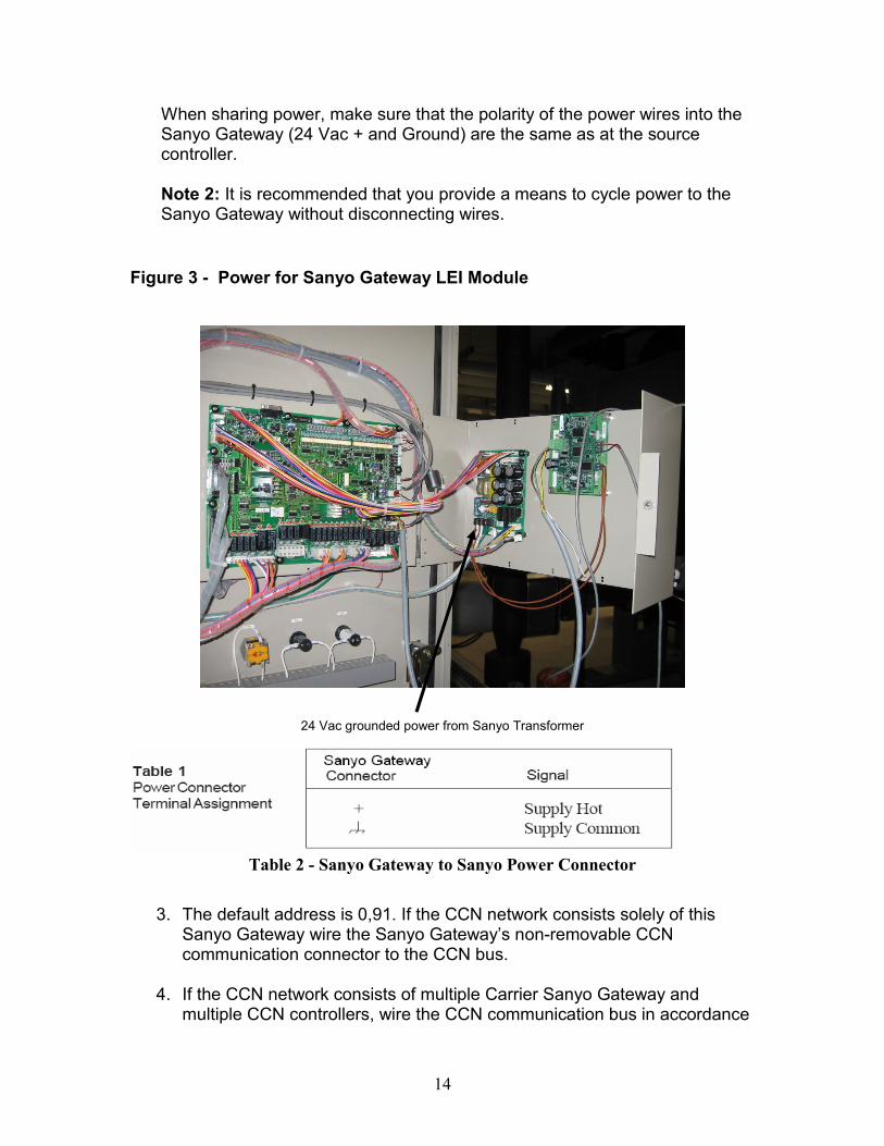
When sharing power, make sure that the polarity of the power wires into the Sanyo Gateway (24 Vac + and Ground) are the same as at the source controller. Note 2: It is recommended that you provide a means to cycle power to the Sanyo Gateway without disconnecting wires.
Figure 3 - Power for Sanyo Gateway LEI Module
24 Vac grounded power from Sanyo Transformer
Table 2 - Sanyo Gateway to Sanyo Power Connector
3. The default address is 0,91. If the CCN network consists solely of this Sanyo Gateway wire the Sanyo Gateway’s non-removable CCN communication connector to the CCN bus.
4. If the CCN network consists of multiple Carrier Sanyo Gateway and
multiple CCN controllers, wire the CCN communication bus in accordance
15
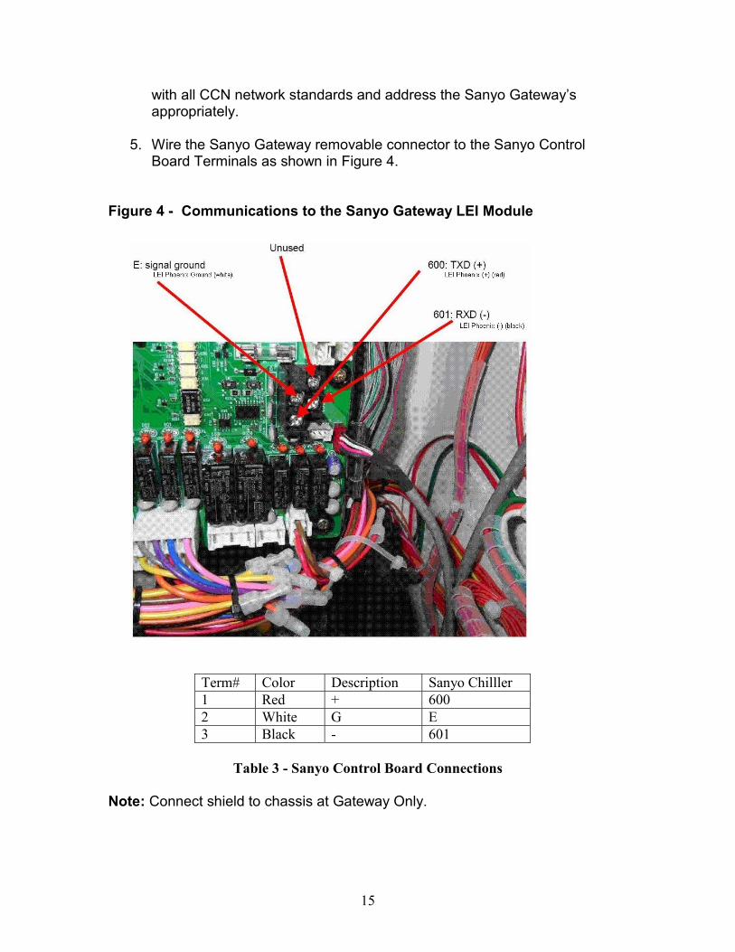
with all CCN network standards and address the Sanyo Gateway’s appropriately.
5. Wire the Sanyo Gateway removable connector to the Sanyo Control
Board Terminals as shown in Figure 4. Figure 4 - Communications to the Sanyo Gateway LEI Module
Term# Color Description Sanyo Chilller 1 Red + 600 2 White G E 3 Black - 601
Table 3 - Sanyo Control Board Connections
Note: Connect shield to chassis at Gateway Only.
16
Sanyo Gateway Functions
The Sanyo Gateway’s integrates a Sanyo Absorption Chiller/Heater onto a Carrier Communicating Network (CCN). o Automatic determination of Sanyo Chiller. o Display Sanyo controller data in CCN Status and Maintenance Tables. o Configuration and Setpoint Tables. o Time Schedule Table. o Get/Set Sanyo controller time and date. o Start/Stop the chiller from CCN. o Annunciate and display Sanyo alarm states and current alarm code. o Chillervisor System Manager. o Alarm History.
Sanyo Chiller Type
On POR the Gateway shall determine from the Sanyo control its Chiller Type (16DJ, 16NK, 16TJ or 16LJ). Once the type has been determined, the uploaded Status Tables (STATUS and OPERSTAT) will contain only data that is applicable to the type and the Table names will be changed to indicate the determined chiller type, i.e.16DJSTAT and 16DJOPER. If the Gateway Tables are uploaded before the Gateway is connected to the Sanyo controller, then the default Tables will be read which contain all data. If this should happen the controller should be deleted and re-uploaded after Gateway/Controller communication has been established.
Status and Maintenance Tables
There are two Status Display Tables and four Maintenance Tables. Status: 1. Status Table which shows Sanyo Chiller sensor analog and discrete
values as well as some calculated parameters. 2. Operational Table which contains hours of operation and number of
starts. Maintenance: 1. Global Occupancy Equipment Table that shows the current occupancy
state and last and next occupancy times. 2. Alarm Status Table that shows current alarm code and alarm
description 3. Chillervisor System Manager Table that shows measured and
calculated parameters. 4. Gateway Messages Table that shows a list of the last 10 Gateway to
Sanyo Controller messages sent.
17
Configuration and Setpoint Tables There are four Configuration Tables and one Setpoint Table. Configuration: 1. Global Occupancy Table that can be configured in tabular form. When
configured, the Occupancy Table will control the starting and stopping of the Sanyo Chiller.
2. Consumable Configuration is used to define up to 16 consumable points from the Status Display Table.
3. Runtime Configuration is used to define up to 16 runtime points from the Status Display Table.
4. Alarm Configuration sets the CCN alarm message parameters. Setpoint: The single Setpoint Table contains five parameters. The first two are the chilled and hot water setoints that are read from the Sanyo controller. These values can be modified from the Sanyo control panel and are copied to the Gateway Setpoint Table or can be modified in the Gateway and are copied to the Sanyo controller. The final three parameters are used by the Gateway for percent load calculation as part of Chiller System Manager support.
Time Schedule Table
The Time Schedule Table provides a graphical method of configuring the Global Occupancy Configuration Table.
Get/Set Time & Date
The Sanyo Gateway contains a software clock that is set from the Sanyo controller on POR and updated every 12 hours. If the Gateway time and date is reset from CCN then the Gateway writes the new date and time to the Sanyo Controller.
Start/Stop Chiller The Sanyo chiller can be started and stopped by forcing the CHIL_S_S point on the first Status screen. In addition, starting and stopping can be controlled by the Global Occupancy schedule. To prevent excessive start/stop cycling of the chiller, a temporary “Safety” level force is applied to the CHIL_S_S point that remains in effect for 3 minutes. After 3 minutes the Safety level is replace by the normal Service level force.
18
Sanyo Alarms CCN alarms are annunciated whenever a change in the Sanyo alarm or alert code is detected. Additional alarms are also generated when a loss of communication occurs between the Gateway and the Sanyo controller.
Chillervisor System Manager
The CHILLERVISOR System Manager (CSM) is a device that coordinates multiple chillers to provide optimum chilled water capacity.
Alarm History Alarm History records the last 25 alarms that have been annunciated to the Carrier Comfort Network.
19
Operator Interface Carrier user interfaces (including ComfortVIEW, CCNWeb, i-Vu, CarrierOne and the System Pilot) are the operator interface to the Sanyo Gateway. With the Sanyo Gateway connected to a Sanyo controller and a Carrier Comfort Network (CCN), an operator can add the Sanyo chiller to the user interface database and upload the Tables. The default address of the Sanyo Gateway is bus = 0, element = 191. The default baud rate is 9600 baud. An operator working at a user interface can:
o Display a list of the points that show current conditions in the Sanyo controller.
o Modify selected points (force an override) or return them to local control (auto an override).
o Display configuration and maintenance screens and change configuration data.
o Create graphics (if supported by the user interface) There are a total of 11 tabular screens that are uploaded from the Gateway.
o Points screen (16xxSTAT and 16xxOPER, where xx can be either DJ, NK, TJ or LJ).
o Maintenance screen (OCCPC01M, ALRM-MNT, CSM-MNT and MESSAGES)
o Occupancy Configuration screen (OCCPC01C). o Alarm Configuration screen (ALRM-CFG). o Runtime Equipment Configuration screen (RUN-POC1). o Consumable Equipment Configuration screen (CNS-POC1). o Controller Identification screen (CTRL-ID).
The first Points screen displays the current status of chiller parameters such as status codes, setpoints and operating temperatures. The status of some of the points can be modified by the operator using a Force function, which can be removed using an Auto function. These forcible points are:
Name Desciption Value OCC Occupied ? Yes/No CHIL_S_S Chiller/Heater Strt/Stop Start/Stop DEM_LIM Demand Limit XXX.X % LCW_STPT Chilled Water Temp STPT XXX.X ° F/ ° C LHW_STPT Hot Water Temp STPT XXX.X ° F/ ° C
The second Points screen shows hours of operation and number of starts.
20
The Maintenance screens are used to monitor the operation of the Sanyo Gateway. OCCPC01M shows the current occupancy state of the Time Schedule. ALRM-MNT shows the current Sanyo alarm code. CSM-MNT shows the percent load data used for the Chillervisor. MESSAGES shows the last 10 messages sent from the Gateway to the Sanyo controller. The OCCPC01C Configuration screen allows tabular configuration of the Gateway’s Time Schedule. The Runtime and Consumable Equipment Configuration screens are RUN-POC1 and CONS-POC1. If Sanyo Gateway points are to be used in conjunction with the Runtime and Consumable supervisory parts of a Data Collection Option, this is where the point names and types of those point names are entered. The Alarm configuration screen (ALRM-CFG ) is a listing of Sanyo Gateway’s alarm configuration parameters such as Alarm System Name and Re-Alarm Time. The Controller Identification screen lists Sanyo Gateway parameters such as device name, description and location, and software and assembly part numbers. The table named CTLR-ID is selected to display this screen.
The Sanyo Gateway can display units in either imperial or metric format when used with an appropriate Carrier user interface.

21
Network Functions
The Carrier communicating network functions that are relevant to a Sanyo Gateway is the Data Collection and Data Transfer Options
Data Collection
The Data Collection Option can be used to collect data from any point in the two Status Display Tables. Points must be specified by name and type when configuring the Data Collection Option’s supervisory part. Consumable and Runtime point names and types must also be configured in the Sanyo Gateway equipment parts (CONS-POC1 and RUN-POC1). For more information on the Data Collection Option, refer to the Data Collection IV Overview and Configuration Manual (808-208).
Data Transfer
The Data Transfer Option can be used to read data from any point in the two Status Display Tables or to write to a forcible point the first Status Display Tables. To transfer data from the Sanyo Gateway a valid point name in either of the two Status Display Tables is configured in the “Source Variable Name”, in the Data Transfer module. These point names are also used when transferring data to the Gateway. A data transfer to a point results in a controller force on that point. For this reason, it is recommended that caution be used when transferring data to the Sanyo Gateway. For more information on the Data Collection Option, refer to the Data Transfer Option Overview and Configuration Manual (808-557).

22
23
Configuration

24

25
Configuration
General Information This section shows the screens that are uploaded for the four Sanyo chiller types. The only screens that are chiller type specific are the two Status Display screens that only contain the points that are relevant to the particular type. Specific information regarding individual parameters is given following each screen. Note that for the remote Chiller Stop command to work the Sanyo control panel must have the REMOTE signal R-SIGN to be configured as PULSE.
Points Screens The Points list is used to select the Point Status screens. The Point Status screens displays current conditions read from the Sanyo controller chiller as well as internal Sanyo Gateway parameters. The Carrier user interface's force operation can be used to modify the values of some of the Sanyo Gateway points. Transmitting a force command to one of these points causes its value to change and the SUPVSR force message to be displayed against the point. Using the Auto operation removes the SUPVSR force message from the screen. Autoing the point does not return to the value it had before being forced. If a force is applied the CHIL_S_S point to start or stop the chiller, then to prevent excessive cycling, a temporary “Safety” level force is applied to CHIL_S_S that remains in effect for 3 minutes. After 3 minutes the Safety level is replace by the normal Service level force. Force commands can come from an operator via a user interface, or from other devices on the Carrier communicating network, such as CHILLERVISOR System Manager, Data Transfer, or BEST ++. Figures 5 through 9 show the first Point’s screen that contains Sanyo controller point status values. The particular screen that is uploaded is dependent on the chiller type, which is automatically determined by the Gateway on POR.

26
Figure 5 – Point Status screen (STATUS) This screen is uploaded when the Sanyo Gateway is not connected to the Sanyo controller.

27
Figure 6 – Point Status screen (16DJSTAT) This screen is uploaded when the Sanyo Gateway is connected to a 16DJ Sanyo controller.
28
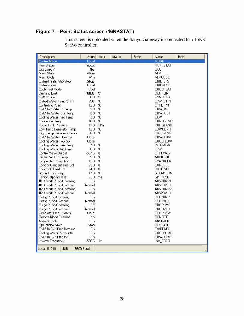
Figure 7 – Point Status screen (16NKSTAT) This screen is uploaded when the Sanyo Gateway is connected to a 16NK Sanyo controller.
29
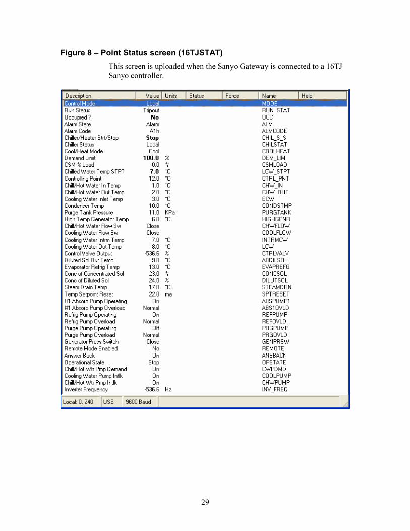
Figure 8 – Point Status screen (16TJSTAT) This screen is uploaded when the Sanyo Gateway is connected to a 16TJ Sanyo controller.
30
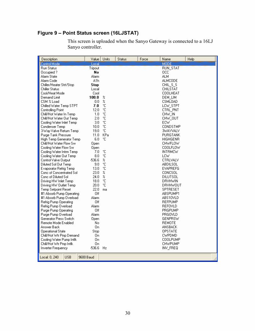
Figure 9 – Point Status screen (16LJSTAT) This screen is uploaded when the Sanyo Gateway is connected to a 16LJ Sanyo controller.
31
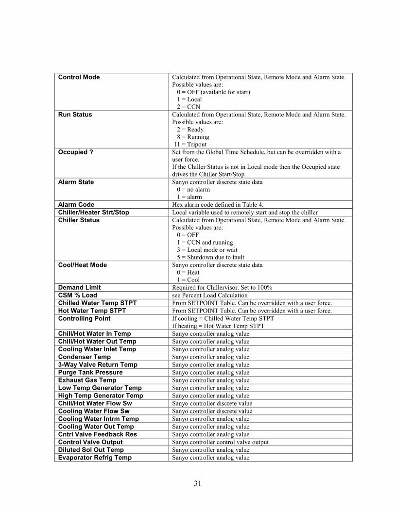
Control Mode Calculated from Operational State, Remote Mode and Alarm State.
Possible values are: 0 = OFF (available for start) 1 = Local 2 = CCN
Run Status Calculated from Operational State, Remote Mode and Alarm State. Possible values are: 2 = Ready 8 = Running 11 = Tripout
Occupied ? Set from the Global Time Schedule, but can be overridden with a user force. If the Chiller Status is not in Local mode then the Occupied state drives the Chiller Start/Stop.
Alarm State Sanyo controller discrete state data 0 = no alarm 1 = alarm
Alarm Code Hex alarm code defined in Table 4. Chiller/Heater Strt/Stop Local variable used to remotely start and stop the chiller Chiller Status Calculated from Operational State, Remote Mode and Alarm State.
Possible values are: 0 = OFF 1 = CCN and running 3 = Local mode or wait 5 = Shutdown due to fault
Cool/Heat Mode Sanyo controller discrete state data 0 = Heat 1 = Cool
Demand Limit Required for Chillervisor. Set to 100% CSM % Load see Percent Load Calculation Chilled Water Temp STPT From SETPOINT Table. Can be overridden with a user force. Hot Water Temp STPT From SETPOINT Table. Can be overridden with a user force. Controlling Point If cooling = Chilled Water Temp STPT
If heating = Hot Water Temp STPT Chill/Hot Water In Temp Sanyo controller analog value Chill/Hot Water Out Temp Sanyo controller analog value Cooling Water Inlet Temp Sanyo controller analog value Condenser Temp Sanyo controller analog value 3-Way Valve Return Temp Sanyo controller analog value Purge Tank Pressure Sanyo controller analog value Exhaust Gas Temp Sanyo controller analog value Low Temp Generator Temp Sanyo controller analog value High Temp Generator Temp Sanyo controller analog value Chill/Hot Water Flow Sw Sanyo controller discrete value Cooling Water Flow Sw Sanyo controller discrete value Cooling Water Intrm Temp Sanyo controller analog value Cooling Water Out Temp Sanyo controller analog value Cntrl Valve Feedback Res Sanyo controller analog value Control Valve Output Sanyo controller control valve output Diluted Sol Out Temp Sanyo controller analog value Evaporator Refrig Temp Sanyo controller analog value

32
Conc Solution Temp Sanyo controller analog value Conc of Concentrated Sol Sanyo controller analog value Conc of Diluted Sol Sanyo controller analog value Steam Drain Temp Sanyo controller analog value Driving HW Inlet Temp Sanyo controller analog value Driving HW Outlet Temp Sanyo controller analog value Temp Setpoint Reset Sanyo controller analog value #1 Absorb Pump Operating Sanyo controller discrete value #1 Absorb Pump Overload Sanyo controller discrete value #2 Absorb Pump Operating Sanyo controller discrete value #2 Absorb Pump Overload Sanyo controller discrete value Refrig Pump Operating Sanyo controller discrete value Refrig Pump Overload Sanyo controller discrete value Purge Pump Operating Sanyo controller discrete value Purge Pump Overload Sanyo controller discrete value Ventilation Fan Intlk Sanyo controller discrete value Generator Press Switch Sanyo controller discrete value Remote Mode Enabled Sanyo controller discrete state data
0 = Local 1 = Remote
Answer Back Sanyo controller discrete state data 0 = Off 1 = On
Operational State Sanyo controller discrete state data 0 = Off 1 = On
Chill/Hot Wtr Pmp Demand Sanyo controller discrete state data Cooling Water Pump Intlk Sanyo controller discrete value
0 = Off 1 = On
Chill/Hot Wtr Pmp Intlk Sanyo controller discrete state data 0 = Off 1 = On
Inverter Frequency Sanyo controller inverter frequency Remote Chiller Start Sequence
When the chiller is in a stop state (OPSTATE = Stop & CHIL_S_S = Stop) and remote is enabled (REMOTE = Yes), then forcing CHIL_S_S to Start will cause the following sequence of events.
o CHIL_S_S goes to Start with a “Safety” force which prevents it from being forced off for 3 minutes.
o A command is sent to the Sanyo control to remotely start the chiller. At this point the following parameters should be in these states.
Chill/Hot Wtr Pmp Demand off Cooling Water Pump Intlk off Chill/Hot Wtr Pmp Intlk off Answer Back off Operational State stop
33
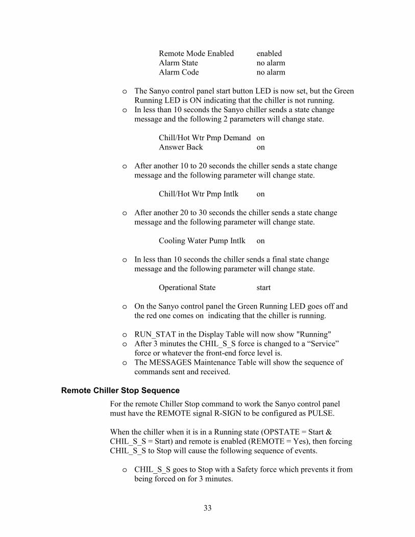
Remote Mode Enabled enabled Alarm State no alarm Alarm Code no alarm
o The Sanyo control panel start button LED is now set, but the Green Running LED is ON indicating that the chiller is not running.
o In less than 10 seconds the Sanyo chiller sends a state change message and the following 2 parameters will change state.
Chill/Hot Wtr Pmp Demand on Answer Back on
o After another 10 to 20 seconds the chiller sends a state change message and the following parameter will change state.
Chill/Hot Wtr Pmp Intlk on
o After another 20 to 30 seconds the chiller sends a state change message and the following parameter will change state.
Cooling Water Pump Intlk on
o In less than 10 seconds the chiller sends a final state change message and the following parameter will change state.
Operational State start
o On the Sanyo control panel the Green Running LED goes off and the red one comes on indicating that the chiller is running.
o RUN_STAT in the Display Table will now show "Running" o After 3 minutes the CHIL_S_S force is changed to a “Service”
force or whatever the front-end force level is. o The MESSAGES Maintenance Table will show the sequence of
commands sent and received. Remote Chiller Stop Sequence
For the remote Chiller Stop command to work the Sanyo control panel must have the REMOTE signal R-SIGN to be configured as PULSE. When the chiller when it is in a Running state (OPSTATE = Start & CHIL_S_S = Start) and remote is enabled (REMOTE = Yes), then forcing CHIL_S_S to Stop will cause the following sequence of events.
o CHIL_S_S goes to Stop with a Safety force which prevents it from
being forced on for 3 minutes.

34
o A command is sent to the Sanyo control to remotely stop the chiller. At this point the following parameters should be in these states.
Chill/Hot Wtr Pmp Demand on Cooling Water Pump Intlk on Chill/Hot Wtr Pmp Intlk on Answer Back on Operational State start Remote Mode Enabled enabled Alarm State no alarm Alarm Code no alarm
o The Sanyo control panel stop button LED is now set, but the Red Running LED is on indicating that the chiller is still running.
o After about 120 seconds the chiller sends a state change message and the following 2 parameters will change state.
Cooling Water Pump Intlk off Answer Back off
o After another 600 seconds the chiller sends a state change message and the following parameter will change state.
Chill/Hot Wtr Pmp Demand off
o In less than 10 seconds the chiller sends a final state change message and the following parameter will change state.
Chill/Hot Wtr Pmp Intlk off Operational State stop
o RUN_STAT in the Display Table will now show "Ready" o After 3 minutes the CHIL_S_S force is changed to a “Service”
force or whatever the front-end force level is. o The MESSAGES Maintenance Table will show the sequence of
commands sent and received.

35
Figures 10 through 12 show the second Point’s screen that contains Sanyo controller operating values. The particular screen that is uploaded is dependent on the chiller type, which is automatically determined by the Gateway on POR. Figure 10 – Point Status screen (OPERSTAT & 16DJOPER)
This screen is uploaded when the Sanyo Gateway is either not connected to a Sanyo controller or is connected to a 16DJ Sanyo controller.
Figure 11 – Point Status screen (16NKOPER ) This screen is uploaded when the Sanyo Gateway is connected to a 16NK Sanyo controller.

36
Figure 12 – Point Status screen (16TJOPER or 16LJOPER) This screen is uploaded when the Sanyo Gateway is connected to a 16TJ or 16LJ Sanyo controller.
Absorption Chiller Sanyo controller discrete state data
No = Other chiller Yes = Absorption chiller
Operating Hours Absorption Chiller/Heater Sanyo controller operating hours #1 Absorbent Pump Sanyo controller operating hours #2 Absorbent Pump Sanyo controller operating hours Refrigerant Pump Sanyo controller operating hours Combustion Sanyo controller operating hours Purge Pump Sanyo controller operating hours Start/Stop Times Absorption Chiller/Heater Sanyo controller start/stop times #1 Absorbent Pump Sanyo controller start/stop times #2 Absorbent Pump Sanyo controller start/stop times Refrigerant Pump Sanyo controller start/stop times Combustion Sanyo controller start/stop times Purge Pump Sanyo controller start/stop times
37
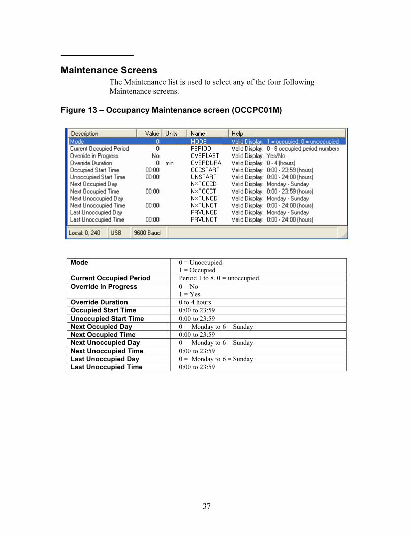
Maintenance Screens The Maintenance list is used to select any of the four following Maintenance screens.
Figure 13 – Occupancy Maintenance screen (OCCPC01M)
Mode 0 = Unoccupied 1 = Occupied
Current Occupied Period Period 1 to 8. 0 = unoccupied. Override in Progress 0 = No
1 = Yes Override Duration 0 to 4 hours Occupied Start Time 0:00 to 23:59 Unoccupied Start Time 0:00 to 23:59 Next Occupied Day 0 = Monday to 6 = Sunday Next Occupied Time 0:00 to 23:59 Next Unoccupied Day 0 = Monday to 6 = Sunday Next Unoccupied Time 0:00 to 23:59 Last Unoccupied Day 0 = Monday to 6 = Sunday Last Unoccupied Time 0:00 to 23:59

38
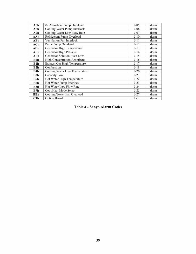
Figure 14 – Alarm Maintenance screen (ALRM-MNT) This screen shows the current Sanyo alarm code together with a description.
Alarm Code Alarm code from the following table. 2-line alarm description from the following table.
CODE DESCRIPTION Panel Symbol
ALARM /ALERT
A0h No Alarm none 61h Chilled/Hot Water Inlet Temperature Sensor F-01 alarm 62h Cooling Water Inlet Temperature Sensor F-02 alarm 63h Cooling Water Outlet Temperature Sensor F-03 alarm 64h Cooling Water Intermediate Temperature Sensor F-04 alarm 65h Condenser Refrigerant Temperature Sensor F-05 alarm 66h Steam Drain Temperature Sensor F-06 alarm 67h Low Temperature Generator Temperature Sensor F-07 alarm 68h Evaporator Refrigerant Temperature Sensor F-08 alarm 69h Driving Hot Water Inlet Temperature Sensor F-09 alarm 6Ah 3-Way Valve Return Temperature Sensor F-10 alarm 6Bh Driving Hot Water Outlet Temperature Sensor F-11 alarm 6Ch Absorbent Diluted Solution Temperature Sensor F-12 alarm 70h Concentrated Solution Temperature Sensor F-16 alarm 75h CPU F-21 alarm 76h Memory F-22 alarm 77h Time Setting F-23 alarm 78h Constant Setting F-24 alarm 79h Chilled/Hot Water Outlet Temperature Sensor F-25 alarm 7Ah High Temperature Generator Temperature Sensor F-26 alarm 7Bh Steam Drain/Exhaust Gas Temperature Sensor F-27 alarm 7Ch Purge Tank Pressure Detector F-28 alarm 81h Operate Purge Pump H-01 alert 83h Clean Cooling Water Tubes H-03 alert 84h Check Cooling Water System H-04 alert 85h Clean Chamber H-05 alert 86h Purge Tank High Pressure H-06 alert 87h Cooling Water Tubes Foul H-07 alert 88h Cooling Water High Temperature H-08 alert 8Ah Power Failure H-10 alert A1h Chilled Water Low Temperature J-01 alarm A2h Chilled Water Pump Interlock J-02 alarm A3h Chilled Water Low Flow Rate J-03 alarm A4h #1 Absorbent Pump Overload J-04 alarm
39
A5h #2 Absorbent Pump Overload J-05 alarm A6h Cooling Water Pump Interlock J-06 alarm A7h Cooling Water Low Flow Rate J-07 alarm AAh Refrigerant Pump Overload J-10 alarm ABh Ventilation Fan Interlock J-11 alarm ACh Purge Pump Overload J-12 alarm ADh Generator High Temperature J-13 alarm AEh Generator High Pressure J-14 alarm AFh Generator Solution Even Low J-15 alarm B0h High Concentration Absorbent J-16 alarm B1h Exhaust Gas High Temperature J-17 alarm B2h Combustion J-18 alarm B4h Cooling Water Low Temperature J-20 alarm B5h Capacity Low J-21 alarm B6h Hot Water High Temperature J-22 alarm B7h Hot Water Pump Interlock J-23 alarm B8h Hot Water Low Flow Rate J-24 alarm B9h Cool/Heat Mode Select J-25 alarm BBh Cooling Tower Fan Overload J-27 alarm C1h Option Board L-01 alarm
Table 4 - Sanyo Alarm Codes

40
Figure 15 – Chillervisor Maintenance screen (CSM-MNT) This screen shows the current values used for the Percent Load Calculation used for the Chillervisor support.
Operational State From the Point Status Table
Start High Temp Gen Temp Saved value High Temp Generator Temp From the Point Status Table Conc Solution Temp From the Point Status Table Ramp Timer Used for time delay Ramping % Load Calculated Running % Load Calculated CSM % Load Either Ramping or Running % Load Chill/Hot Water In Temp From the Point Status Table Chill/Hot Water OutTemp From the Point Status Table Cooling Water Inlet Temp From the Point Status Table Cooling Water Outlet Temp From the Point Status Table
Percent Load Calculation
The Chillervisor system manager determines when to add or remove a chiller from service in a multiple chiller plant. With chillers that provide electrical cooling the chiller load can be measured in relation to the percent of full load amps the chiller is consuming. The Chillervisor system manager has configurable load percentages that are used as a threshold in the “add and remove” chiller routines. In order to determine the loading on an absorption machine we cannot look at full load amps or the valve position on the heat source for the generator. In order to calculate the percent load of the absorption machine it is necessary to evaluate the parameters for the absorption cycle. Several parameters determine how well the absorption machine is performing and from these parameters we can derive a relative refrigeration cycle for the current operation of the machine based on start-up conditions.
41
During the solution warm up cycle the gateway can calculate a percent load based on the percent of the hot solution temperature to the temperature of the primary heating driver in the generator. This allows it to report a ramp loading effect of the absorption cycle. Relative differences of the solution concentration, chilled water differential, and condenser water differential are taken in to account to make sure the absorption cycle is really developing as the solution in the generator warms up. Otherwise the Gateway would report the load as increasing so the Chillervisor would make a determination that something is wrong, stop this machine and start another machine. When the solution is warmed up in the generator and the concentrations of the strong solution and weak solution have spread apart, there is a good differential on the chilled water in and out and a good differential on the condenser water in and out. From this is calculated the machines running load factor. The running load factor is typically in the 50 to 100% range based on the hot solution temperature and is factored by the strong solution percentage, the condenser water temperature and the chilled water difference. A high load percentage is reported when the strong concentration approaches within 6 or 7 % of the solidification concentration of 70%. This ensures Chillervisor starts the process of adding another machine to assist with the load before the concentration becomes high enough to cause this machine to shut down. When the machine is requested to shut down it will typically go through a dilution cycle. The loading is calculated as a number from 50% down to 0% based on the relative difference of the solution concentrations.
The following formulas are used to calculate %load of the chiller. Ramp Loading just after starting: % Ramping load = (High temp Generator temp – High temp Generator temp at startup) * 100 (Max temp of the generator - High temp Generator temp at startup) Where the Max temp of the generator has the following values for each machine type.
• 16TJ & 16LJ single effect = 105 C
• 16DJ & 16NK double effect = 162 C
42
Simultaneously the following calculation is performed which will become the % Running load and the Dilution Cycle percent Load. % Running load = (% Conc of Concentrated sol – Design condition of diluted sol) * 100
(64.9 - Design condition of diluted sol) The design condition of the diluted solution is a user configurable value with the default value of 55% and a range of 52% to 57% During Ramp loading the values of chilled water and condenser water delta should be increasing such that the following delta temperatures are positive values. Delta Chilled water = chilled water return temp – chilled water supply temp Delta Condenser water = condenser water leaving temp – condenser water entering temp When the concentration % Running load becomes equal to or greater than the % Ramping load and the two deltas have been increasing for the calculated ramp time, then the calculation switches to the concentration percent load and stays with that till the machine shuts down and goes through a dilution cycle. On start-up, either when the machine transitions from stop to start or if the Gateway is started when the machine is running, a minimum ramp time is calculated based on the difference between the Max temp of the generator and the measured High temp Generator temperature. The following chart is used to set the ramp to monitor the chilled and condenser delta temperature before the % Ramping load using generator temp transitions to % Running load based on concentration. Generator Max temp - High temp Generator at restart Time delay Difference < 20 C 30 sec Difference > 20 C and < 40 C 60 sec Difference > 40 C and < 60 C 120 sec Difference > 60 C 300 seconds If the concentration of concentrated solution becomes 65% or greater then the % load based on the concentrated solution is used without waiting for the ramp delay time to expire. This is because the machine will shut down if it runs too long above 65% on this concentration.
43
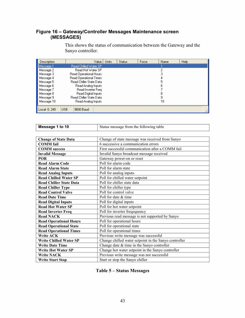
Figure 16 – Gateway/Controller Messages Maintenance screen (MESSAGES)
This shows the status of communication between the Gateway and the Sanyo controller.
Message 1 to 10 Status message from the following table
Change of State Data Change of state message was received from Sanyo COMM fail 6 successive a communication errors COMM success First successful communication after a COMM fail Invalid Message Invalid Sanyo broadcast message received POR Gateway power-on or reset Read Alarm Code Poll for alarm code Read Alarm State Poll for alarm state Read Analog Inputs Poll for analog inputs Read Chilled Water SP Poll for chilled water setpoint Read Chiller State Data Poll for chiller state data Read Chiller Type Poll for chiller type Read Control Valve Poll for control valve Read Date Time Poll for date & time Read Digital Inputs Poll for digital inputs Read Hot Water SP Poll for hot water setpoint Read Inverter Freq Poll for inverter freqequency Read NACK Previous read message is not supported by Sanyo Read Operational Hours Poll for operational hours Read Operational State Poll for operational state Read Operational Times Poll for operational times Write ACK Previous write message was successful Write Chilled Water SP Change chilled water setpoint in the Sanyo controller Write Date Time Change date & time in the Sanyo controller Write Hot Water SP Change hot water setpoint in the Sanyo controller Write NACK Previous write message was not successful Write Start Stop Start or stop the Sanyo chiller
Table 5 – Status Messages
44
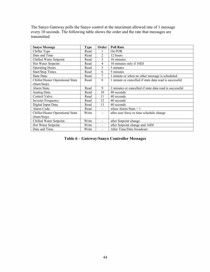
The Sanyo Gateway polls the Sanyo control at the maximum allowed rate of 1 message every 10 seconds. The following table shows the order and the rate that messages are transmitted. Sanyo Message Type Order Poll Rate Chiller Type Read 1 On POR Date and Time Read 2 12 hours Chilled Water Setpoint Read 3 10 minutes Hot Water Setpoint Read 4 10 minutes only if 16DJ Operating Hours Read 5 5 minutes Start/Stop Times. Read 6 5 minutes State Data. Read 7 1 minute or when no other message is scheduled Chiller/Heater Operational State (Start/Stop).
Read 8 1 minute or cancelled if state data read is successful
Alarm State. Read 9 2 minutes or cancelled if state data read is successful Analog Data. Read 10 40 seconds Control Valve Read 11 40 seconds Inverter Frequency Read 12 40 seconds Digital Input Data. Read 13 40 seconds Alarm Code. Read - when Alarm State = 1 Chiller/Heater Operational State (Start/Stop).
Write - after user force or time schedule change
Chilled Water Setpoint. Write - after Setpoint change Hot Water Setpoint. Write - after Setpoint change and 16DJ Date and Time. Write - After Time/Date broadcast
Table 6 – Gateway/Sanyo Controller Messages
45
Configuration Screens
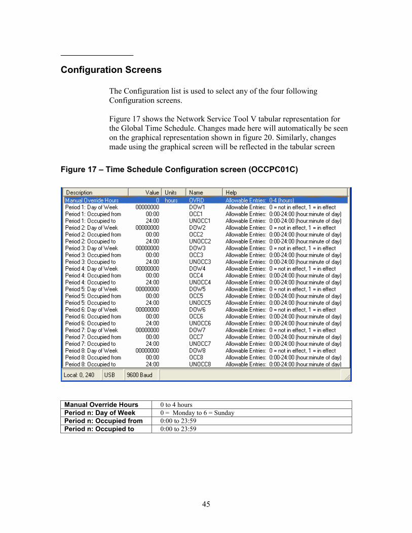
The Configuration list is used to select any of the four following Configuration screens. Figure 17 shows the Network Service Tool V tabular representation for the Global Time Schedule. Changes made here will automatically be seen on the graphical representation shown in figure 20. Similarly, changes made using the graphical screen will be reflected in the tabular screen
Figure 17 – Time Schedule Configuration screen (OCCPC01C)
Manual Override Hours 0 to 4 hours Period n: Day of Week 0 = Monday to 6 = Sunday Period n: Occupied from 0:00 to 23:59 Period n: Occupied to 0:00 to 23:59
46
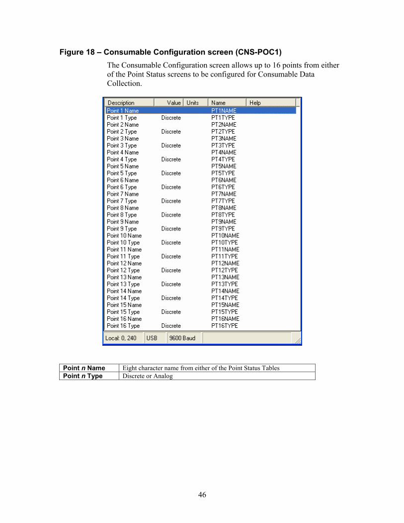
Figure 18 – Consumable Configuration screen (CNS-POC1) The Consumable Configuration screen allows up to 16 points from either of the Point Status screens to be configured for Consumable Data Collection.
Point n Name Eight character name from either of the Point Status Tables Point n Type Discrete or Analog

47
Figure 19 – Runtime Configuration screen (RUN-POC1) The Runtime Configuration screen allows up to 16 points from either of the Point Status screens to be configured for Runtime Data Collection.
Point n Name Eight character name from either of the Point Status Tables Point n Type Discrete or Analog
48
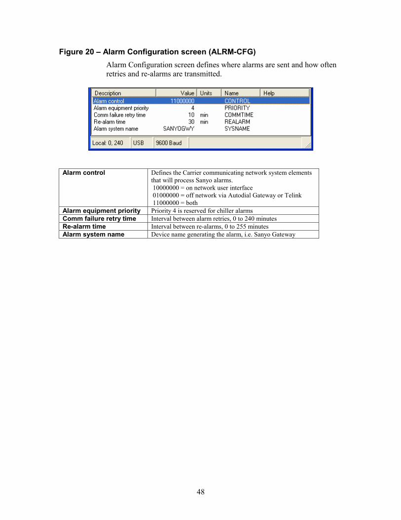
Figure 20 – Alarm Configuration screen (ALRM-CFG) Alarm Configuration screen defines where alarms are sent and how often retries and re-alarms are transmitted.
Alarm control Defines the Carrier communicating network system elements
that will process Sanyo alarms. 10000000 = on network user interface 01000000 = off network via Autodial Gateway or Telink 11000000 = both
Alarm equipment priority Priority 4 is reserved for chiller alarms Comm failure retry time Interval between alarm retries, 0 to 240 minutes Re-alarm time Interval between re-alarms, 0 to 255 minutes Alarm system name Device name generating the alarm, i.e. Sanyo Gateway
49
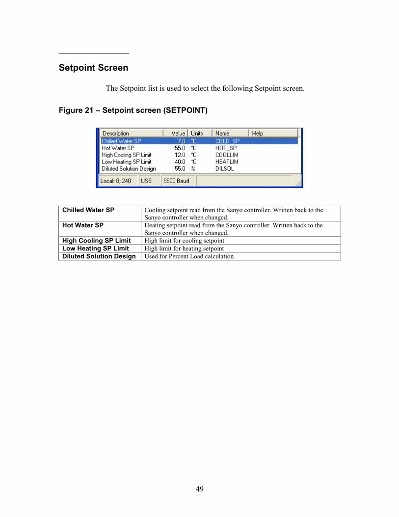
Setpoint Screen
The Setpoint list is used to select the following Setpoint screen. Figure 21 – Setpoint screen (SETPOINT)
Chilled Water SP Cooling setpoint read from the Sanyo controller. Written back to the
Sanyo controller when changed. Hot Water SP Heating setpoint read from the Sanyo controller. Written back to the
Sanyo controller when changed. High Cooling SP Limit High limit for cooling setpoint Low Heating SP Limit High limit for heating setpoint Diluted Solution Design Used for Percent Load calculation
50
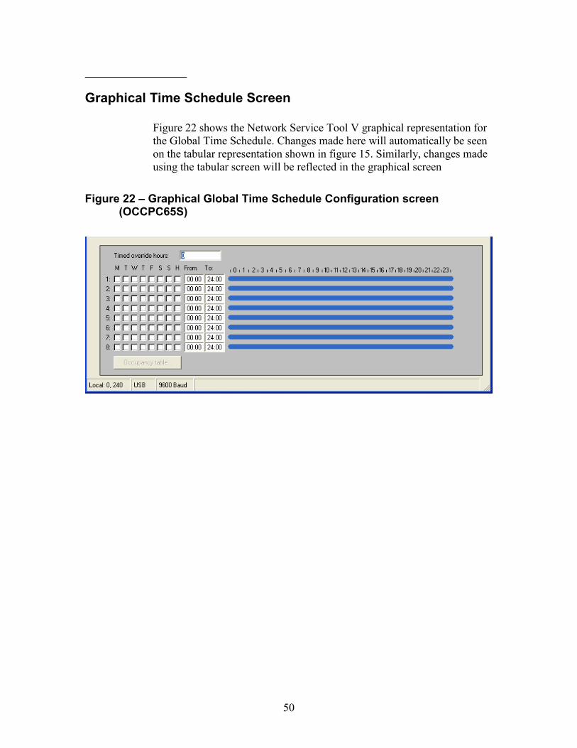
Graphical Time Schedule Screen
Figure 22 shows the Network Service Tool V graphical representation for the Global Time Schedule. Changes made here will automatically be seen on the tabular representation shown in figure 15. Similarly, changes made using the tabular screen will be reflected in the graphical screen
Figure 22 – Graphical Global Time Schedule Configuration screen
(OCCPC65S)
51
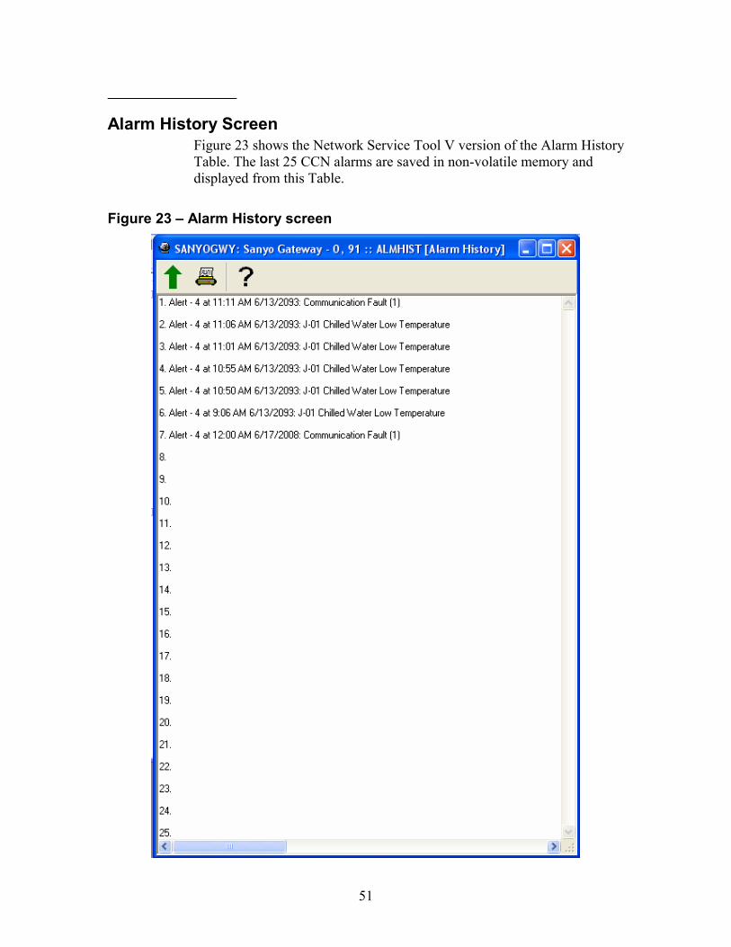
Alarm History Screen Figure 23 shows the Network Service Tool V version of the Alarm History Table. The last 25 CCN alarms are saved in non-volatile memory and displayed from this Table.
Figure 23 – Alarm History screen

52

53

54
11-808-442-01 08/08