sapling converter box · sapling converter box scb-100-000-1 version number 1.2 the sapling...
TRANSCRIPT
Sapling Converter BoxSCB-100-000-1
Version Number 1.2
The Sapling Company, Inc.1633 Republic RoadHuntingdon Valley, PA 19006USA
(+1) 215.322.6063 P.(+1) 215.322.8498 F.www.sapling-inc.com
Current as of March 15, 2015
Installation Manual
The Sapling Company, Inc.1633 Republic RoadHuntingdon Valley, PA 19006USA
P. (+1) 215.322.6063F. (+1) 215.322.8498www.sapling-inc.com
2
Table of Contents
2-Wire Converter Box (SCB-100-000-1)
*Manuals may change without prior notice
Table of Contents—2
Important Safety Instructions—3
System Preparations—4-5
Installing the Converter Box--Wall Mount—6-8
Installing the Converter Box--Rack Mount—9-10
2-Wire Digital Communication and Wiring Information—11
Status Panel—12
Troubleshooting—13-14
Warranty—15
For information on how to install and configure SMA, SAM, or SBD model clocks, please consult the manual for that clock. This manual only covers installation for the converter box.Please be aware that Sapling distributed a different model of converter box prior to July 2014. Older converter boxes can be identified by their lack of external LEDs and unpainted steel covers. For information on the older converter box, please contact Sapling for an older copy of the manual.
The Sapling Company, Inc.1633 Republic RoadHuntingdon Valley, PA 19006USA
P. (+1) 215.322.6063F. (+1) 215.322.8498www.sapling-inc.com
3
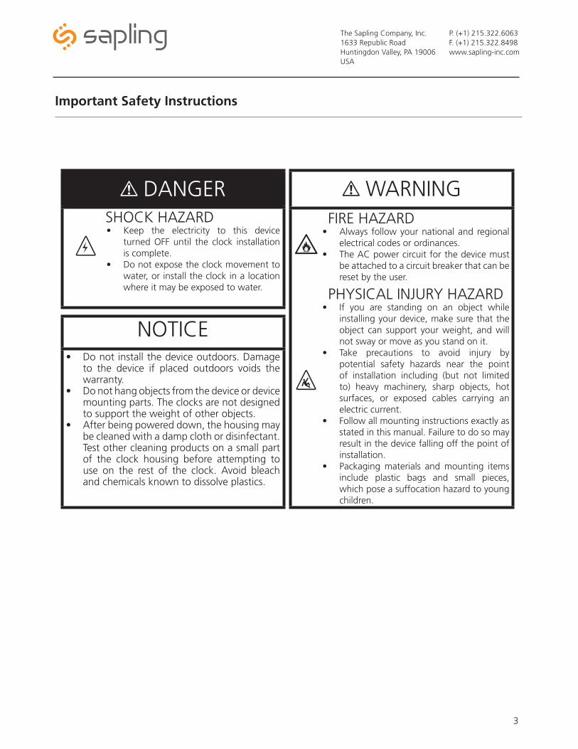
Important Safety Instructions
! DANGERSHOCK HAZARD• Keep the electricity to this device
turned OFF until the clock installation is complete.
• Do not expose the clock movement to water, or install the clock in a location where it may be exposed to water.
! WARNINGFIRE HAZARD
• Always follow your national and regional electrical codes or ordinances.
• The AC power circuit for the device must be attached to a circuit breaker that can be reset by the user.
PHYSICAL INJURY HAZARD• If you are standing on an object while
installing your device, make sure that the object can support your weight, and will not sway or move as you stand on it.
• Take precautions to avoid injury by potential safety hazards near the point of installation including (but not limited to) heavy machinery, sharp objects, hot surfaces, or exposed cables carrying an electric current.
• Follow all mounting instructions exactly as stated in this manual. Failure to do so may result in the device falling off the point of installation.
• Packaging materials and mounting items include plastic bags and small pieces, which pose a suffocation hazard to young children.
NOTICE• Do not install the device outdoors. Damage
to the device if placed outdoors voids the warranty.
• Do not hang objects from the device or device mounting parts. The clocks are not designed to support the weight of other objects.
• After being powered down, the housing may be cleaned with a damp cloth or disinfectant. Test other cleaning products on a small part of the clock housing before attempting to use on the rest of the clock. Avoid bleach and chemicals known to dissolve plastics.
, H
|
The Sapling Company, Inc.1633 Republic RoadHuntingdon Valley, PA 19006USA
P. (+1) 215.322.6063F. (+1) 215.322.8498www.sapling-inc.com
4
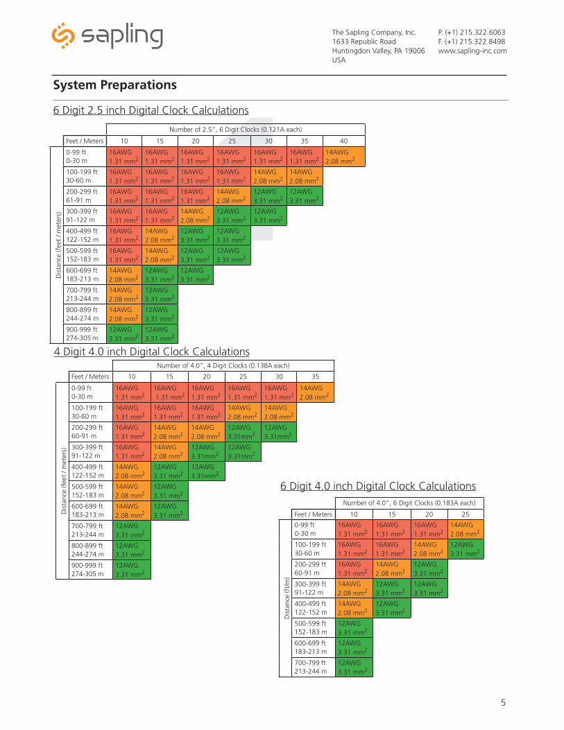
System Preparations
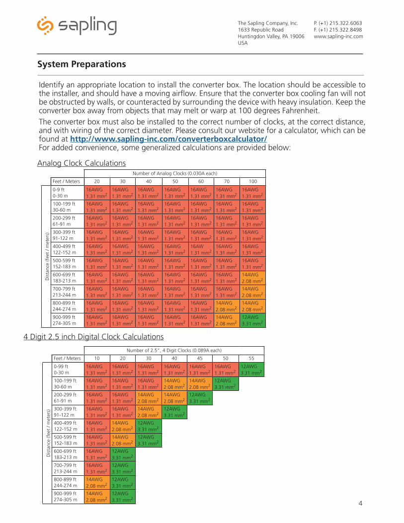
Identify an appropriate location to install the converter box. The location should be accessible to the installer, and should have a moving airflow. Ensure that the converter box cooling fan will not be obstructed by walls, or counteracted by surrounding the device with heavy insulation. Keep the converter box away from objects that may melt or warp at 100 degrees Fahrenheit.The converter box must also be installed to the correct number of clocks, at the correct distance, and with wiring of the correct diameter. Please consult our website for a calculator, which can be found at http://www.sapling-inc.com/converterboxcalculator/For added convenience, some generalized calculations are provided below:
Number of Analog Clocks (0.030A each)
Feet / Meters 20 30 40 50 60 70 100
Dis
tanc
e (f
eet
/ met
ers)
0-9 ft 0-30 m
16AWG 1.31 mm2
16AWG1.31 mm2
16AWG1.31 mm2
16AWG1.31 mm2
16AWG1.31 mm2
16AWG1.31 mm2
16AWG1.31 mm2
100-199 ft30-60 m
16AWG1.31 mm2
16AWG1.31 mm2
16AWG1.31 mm2
16AWG1.31 mm2
16AWG1.31 mm2
16AWG1.31 mm2
16AWG1.31 mm2
200-299 ft61-91 m
16AWG1.31 mm2
16AWG1.31 mm2
16AWG1.31 mm2
16AWG1.31 mm2
16AWG1.31 mm2
16AWG1.31 mm2
16AWG1.31 mm2
300-399 ft91-122 m
16AWG1.31 mm2
16AWG1.31 mm2
16AWG1.31 mm2
16AWG1.31 mm2
16AWG1.31 mm2
16AWG1.31 mm2
16AWG1.31 mm2
400-499 ft122-152 m
16AWG1.31 mm2
16AWG1.31 mm2
16AWG1.31 mm2
16AWG1.31 mm2
16AW1.31 mm2
16AWG1.31 mm2
16AWG1.31 mm2
500-599 ft152-183 m
16AWG 1.31 mm2
16AWG1.31 mm2
16AWG1.31 mm2
16AWG1.31 mm2
16AWG1.31 mm2
16AWG1.31 mm2
16AWG1.31 mm2
600-699 ft183-213 m
16AWG1.31 mm2
16AWG1.31 mm2
16AWG1.31 mm2
16AWG1.31 mm2
16AWG1.31 mm2
16AWG1.31 mm2
14AWG2.08 mm2
700-799 ft213-244 m
16AWG1.31 mm2
16AWG1.31 mm2
16AWG1.31 mm2
16AWG1.31 mm2
16AWG1.31 mm2
16AWG1.31 mm2
14AWG2.08 mm2
800-899 ft244-274 m
16AWG1.31 mm2
16AWG1.31 mm2
16AWG1.31 mm2
16AWG1.31 mm2
16AWG1.31 mm2
14AWG2.08 mm2
14AWG2.08 mm2
900-999 ft274-305 m
16AWG1.31 mm2
16AWG1.31 mm2
16AWG1.31 mm2
16AWG1.31 mm2
16AWG1.31 mm2
14AWG2.08 mm2
12AWG3.31 mm2
Number of 2.5”, 4 Digit Clocks (0.089A each)
Feet / Meters 10 20 30 40 45 50 55
Dis
tanc
e (f
eet
/ met
ers)
0-99 ft0-30 m
16AWG1.31 mm2
16AWG1.31 mm2
16AWG1.31 mm2
16AWG1.31 mm2
16AWG1.31 mm2
16AWG1.31 mm2
12AWG3.31 mm2
100-199 ft30-60 m
16AWG1.31 mm2
16AWG1.31 mm2
16AWG1.31 mm2
14AWG2.08 mm2
14AWG2.08 mm2
12AWG3.31 mm2
200-299 ft61-91 m
16AWG1.31 mm2
16AWG1.31 mm2
14AWG2.08 mm2
14AWG2.08 mm2
12AWG3.31 mm2
300-399 ft91-122 m
16AWG1.31 mm2
16AWG1.31 mm2
14AWG2.08 mm2
12AWG3.31 mm2
400-499 ft122-152 m
16AWG1.31 mm2
14AWG2.08 mm2
12AWG3.31 mm2
500-599 ft152-183 m
16AWG1.31 mm2
14AWG2.08 mm2
12AWG3.31 mm2
600-699 ft183-213 m
16AWG1.31 mm2
12AWG3.31 mm2
700-799 ft213-244 m
16AWG1.31 mm2
12AWG3.31 mm2
800-899 ft244-274 m
14AWG2.08 mm2
12AWG3.31 mm2
900-999 ft274-305 m
14AWG2.08 mm2
12AWG3.31 mm2
Analog Clock Calculations
4 Digit 2.5 inch Digital Clock Calculations
1The Sapling Company, Inc.1633 Republic RoadHuntingdon Valley, PA 19006USA
P. (+1) 215.322.6063F. (+1) 215.322.8498www.sapling-inc.com
5
Number of 2.5”, 6 Digit Clocks (0.121A each)
Feet / Meters 10 15 20 25 30 35 40
Dis
tanc
e (f
eet
/ met
ers)
0-99 ft0-30 m
16AWG1.31 mm2
16AWG1.31 mm2
16AWG1.31 mm2
16AWG1.31 mm2
16AWG1.31 mm2
16AWG1.31 mm2
14AWG2.08 mm2
100-199 ft30-60 m
16AWG1.31 mm2
16AWG1.31 mm2
16AWG1.31 mm2
16AWG1.31 mm2
14AWG2.08 mm2
14AWG2.08 mm2
200-299 ft61-91 m
16AWG1.31 mm2
16AWG1.31 mm2
16AWG1.31 mm2
14AWG2.08 mm2
12AWG3.31 mm2
12AWG3.31 mm2
300-399 ft91-122 m
16AWG1.31 mm2
16AWG1.31 mm2
14AWG2.08 mm2
12AWG3.31 mm2
12AWG3.31 mm2
400-499 ft122-152 m
16AWG1.31 mm2
14AWG2.08 mm2
12AWG3.31 mm2
12AWG3.31 mm2
500-599 ft152-183 m
16AWG1.31 mm2
14AWG2.08 mm2
12AWG3.31 mm2
12AWG3.31 mm2
600-699 ft183-213 m
14AWG2.08 mm2
12AWG3.31 mm2
12AWG3.31 mm2
700-799 ft213-244 m
14AWG2.08 mm2
12AWG3.31 mm2
800-899 ft244-274 m
14AWG2.08 mm2
12AWG3.31 mm2
900-999 ft274-305 m
12AWG3.31 mm2
12AWG3.31 mm2
System Preparations
4 Digit 4.0 inch Digital Clock CalculationsNumber of 4.0”, 4 Digit Clocks (0.138A each)
Feet / Meters 10 15 20 25 30 35
Dis
tanc
e (f
eet
/ met
ers)
0-99 ft0-30 m
16AWG1.31 mm2
16AWG 1.31 mm2
16AWG1.31 mm2
16AWG1.31 mm2
16AWG1.31 mm2
14AWG2.08 mm2
100-199 ft30-60 m
16AWG1.31 mm2
16AWG1.31 mm2
16AWG1.31 mm2
14AWG2.08 mm2
14AWG2.08 mm2
200-299 ft60-91 m
16AWG1.31 mm2
14AWG2.08 mm2
14AWG2.08 mm2
12AWG3.31mm2
12AWG3.31mm2
300-399 ft91-122 m
16AWG1.31 mm2
14AWG2.08 mm2
12AWG3.31mm2
12AWG3.31mm2
400-499 ft122-152 m
14AWG2.08 mm2
12AWG3.31 mm2
12AWG3.31mm2
500-599 ft152-183 m
14AWG2.08 mm2
12AWG3.31 mm2
600-699 ft183-213 m
14AWG2.08 mm2
12AWG3.31 mm2
700-799 ft213-244 m
12AWG3.31 mm2
800-899 ft244-274 m
12AWG3.31 mm2
900-999 ft274-305 m
12AWG3.31 mm2
6 Digit 2.5 inch Digital Clock Calculations
6 Digit 4.0 inch Digital Clock CalculationsNumber of 4.0”, 6 Digit Clocks (0.183A each)
Feet / Meters 10 15 20 25
Dis
tanc
e (f
t/m
)
0-99 ft0-30 m
16AWG1.31 mm2
16AWG1.31 mm2
16AWG1.31 mm2
14AWG2.08 mm2
100-199 ft30-60 m
16AWG1.31 mm2
16AWG1.31 mm2
14AWG2.08 mm2
12AWG3.31 mm2
200-299 ft60-91 m
16AWG1.31 mm2
14AWG2.08 mm2
12AWG3.31 mm2
300-399 ft91-122 m
14AWG2.08 mm2
12AWG3.31 mm2
12AWG3.31 mm2
400-499 ft122-152 m
14AWG2.08 mm2
12AWG3.31 mm2
500-599 ft152-183 m
12AWG3.31 mm2
600-699 ft183-213 m
12AWG3.31 mm2
700-799 ft213-244 m
12AWG3.31 mm2
The Sapling Company, Inc.1633 Republic RoadHuntingdon Valley, PA 19006USA
P. (+1) 215.322.6063F. (+1) 215.322.8498www.sapling-inc.com
6
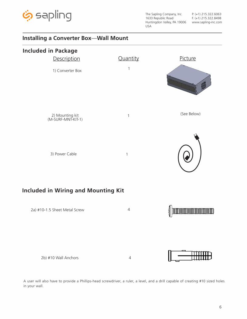
Installing a Converter Box—Wall Mount
Included in Package
1) Converter Box
Description Quantity Picture
2) Mounting kit(M-SURF-MNT-KIT-1)
1
1
Included in Wiring and Mounting Kit
2a) #10-1.5 Sheet Metal Screw 4
A user will also have to provide a Phillips-head screwdriver, a ruler, a level, and a drill capable of creating #10 sized holes in your wall.
2b) #10 Wall Anchors 4
(See Below)
3) Power Cable 1
1 2
3 4
The Sapling Company, Inc.1633 Republic RoadHuntingdon Valley, PA 19006USA
P. (+1) 215.322.6063F. (+1) 215.322.8498www.sapling-inc.com
7
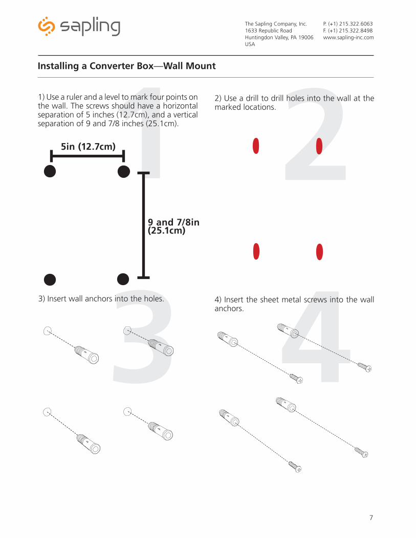
3) Insert wall anchors into the holes.
1) Use a ruler and a level to mark four points on the wall. The screws should have a horizontal separation of 5 inches (12.7cm), and a vertical separation of 9 and 7/8 inches (25.1cm).
Installing a Converter Box—Wall Mount
2) Use a drill to drill holes into the wall at the marked locations.
4) Insert the sheet metal screws into the wall anchors.
5in (12.7cm)
9 and 7/8in (25.1cm)
5 6
7 8
The Sapling Company, Inc.1633 Republic RoadHuntingdon Valley, PA 19006USA
P. (+1) 215.322.6063F. (+1) 215.322.8498www.sapling-inc.com
8
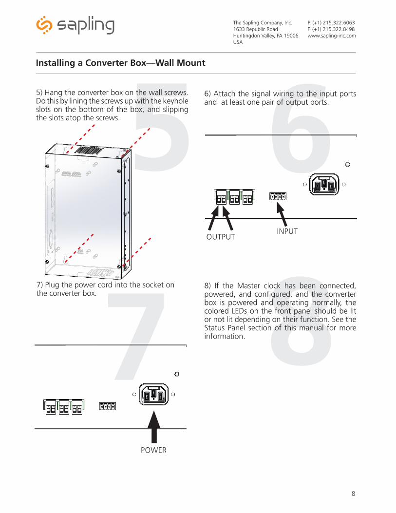
7) Plug the power cord into the socket on the converter box.
5) Hang the converter box on the wall screws. Do this by lining the screws up with the keyhole slots on the bottom of the box, and slipping the slots atop the screws.
Installing a Converter Box—Wall Mount
6) Attach the signal wiring to the input ports and at least one pair of output ports.
8) If the Master clock has been connected, powered, and configured, and the converter box is powered and operating normally, the colored LEDs on the front panel should be lit or not lit depending on their function. See the Status Panel section of this manual for more information.
INPUTOUTPUT
POWER
The Sapling Company, Inc.1633 Republic RoadHuntingdon Valley, PA 19006USA
P. (+1) 215.322.6063F. (+1) 215.322.8498www.sapling-inc.com
9
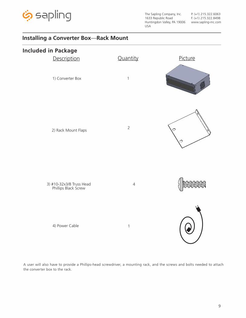
Installing a Converter Box—Rack Mount
Included in Package
1) Converter Box
Description Quantity Picture
2) Rack Mount Flaps
1
2
A user will also have to provide a Phillips-head screwdriver, a mounting rack, and the screws and bolts needed to attach the converter box to the rack.
3) #10-32x3/8 Truss Head Phillips Black Screw
4
4) Power Cable 1
1 2
3 4
The Sapling Company, Inc.1633 Republic RoadHuntingdon Valley, PA 19006USA
P. (+1) 215.322.6063F. (+1) 215.322.8498www.sapling-inc.com
10
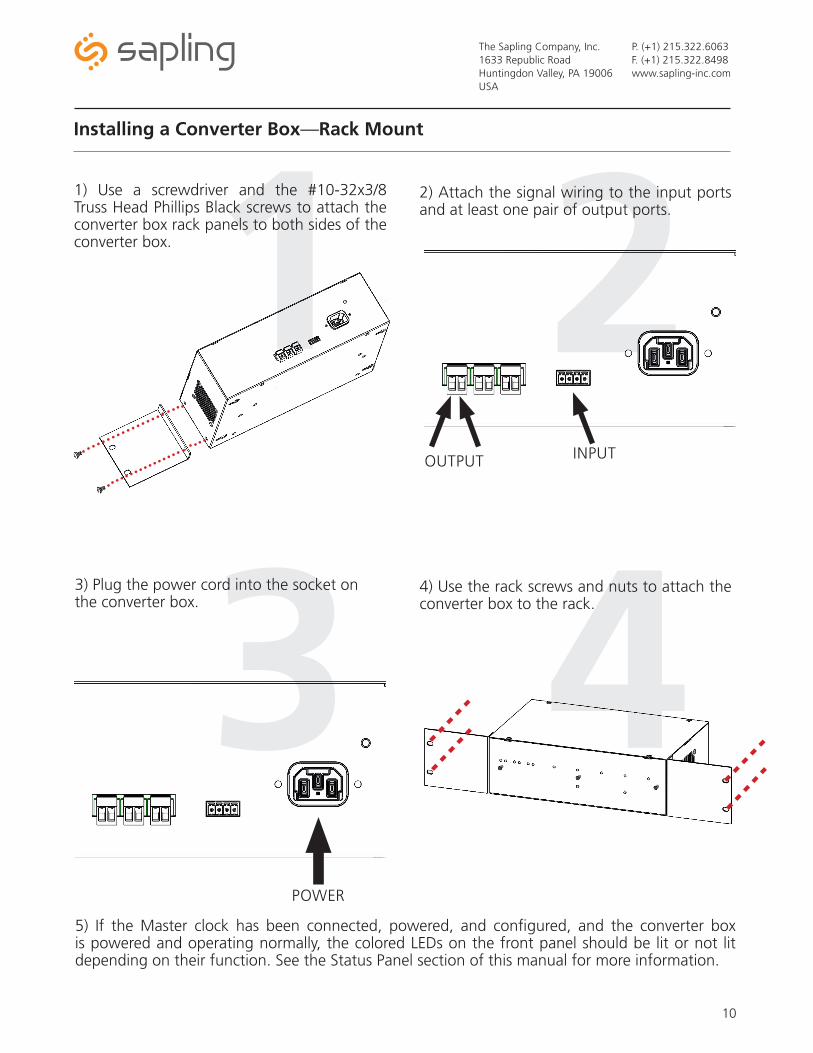
3) Plug the power cord into the socket on the converter box.
1) Use a screwdriver and the #10-32x3/8 Truss Head Phillips Black screws to attach the converter box rack panels to both sides of the converter box.
Installing a Converter Box—Rack Mount
2) Attach the signal wiring to the input ports and at least one pair of output ports.
4) Use the rack screws and nuts to attach the converter box to the rack.
5) If the Master clock has been connected, powered, and configured, and the converter box is powered and operating normally, the colored LEDs on the front panel should be lit or not lit depending on their function. See the Status Panel section of this manual for more information.
INPUTOUTPUT
POWER
The Sapling Company, Inc.1633 Republic RoadHuntingdon Valley, PA 19006USA
P. (+1) 215.322.6063F. (+1) 215.322.8498www.sapling-inc.com
11
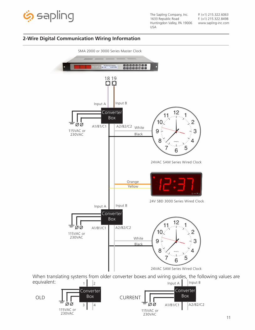
2-Wire Digital Communication Wiring Information
SMA 2000 or 3000 Series Master Clock
24VAC SAM Series Wired Clock
24V SBD 3000 Series Wired Clock
24VAC SAM Series Wired Clock
19
White
Black
White
Black
OrangeYellow
115VAC or 230VAC
18
Input A Input B
A1/B1/C1
A2/B2/C2
Converter Box
Converter
Box
Converter Box
Input A Input B
115VAC or 230VAC
A1/B1/C1
A2/B2/C2
When translating systems from older converter boxes and wiring guides, the following values are equivalent:
115VAC or 230VAC
3 4
Converter
Box
1 2
Converter BoxOLD
A2/B2/C2
Converter
Box
Converter Box
Input A Input B
115VAC or 230VAC
A1/B1/C1
CURRENT
The Sapling Company, Inc.1633 Republic RoadHuntingdon Valley, PA 19006USA
P. (+1) 215.322.6063F. (+1) 215.322.8498www.sapling-inc.com
12
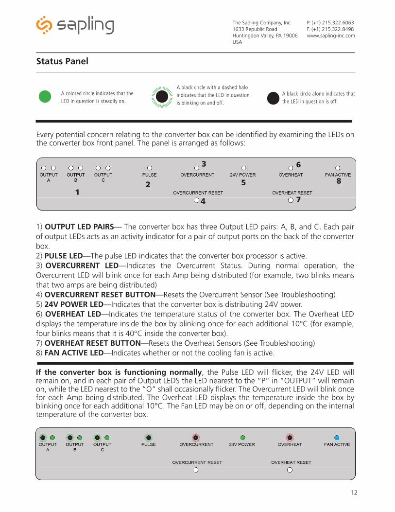
Every potential concern relating to the converter box can be identified by examining the LEDs on the converter box front panel. The panel is arranged as follows:
Status Panel
If the converter box is functioning normally, the Pulse LED will flicker, the 24V LED will remain on, and in each pair of Output LEDS the LED nearest to the “P” in “OUTPUT” will remain on, while the LED nearest to the “O” shall occasionally flicker. The Overcurrent LED will blink once for each Amp being distributed. The Overheat LED displays the temperature inside the box by blinking once for each additional 10°C. The Fan LED may be on or off, depending on the internal temperature of the converter box.
A colored circle indicates that the LED in question is steadily on.
A black circle with a dashed halo indicates that the LED in question is blinking on and off.
A black circle alone indicates that the LED in question is off.
12
3
4
5
6
7
8
1) OUTPUT LED PAIRS— The converter box has three Output LED pairs: A, B, and C. Each pair of output LEDs acts as an activity indicator for a pair of output ports on the back of the converter box.2) PULSE LED—The pulse LED indicates that the converter box processor is active.3) OVERCURRENT LED—Indicates the Overcurrent Status. During normal operation, the Overcurrent LED will blink once for each Amp being distributed (for example, two blinks means that two amps are being distributed)4) OVERCURRENT RESET BUTTON—Resets the Overcurrent Sensor (See Troubleshooting)5) 24V POWER LED—Indicates that the converter box is distributing 24V power.6) OVERHEAT LED—Indicates the temperature status of the converter box. The Overheat LED displays the temperature inside the box by blinking once for each additional 10°C (for example, four blinks means that it is 40°C inside the converter box).7) OVERHEAT RESET BUTTON—Resets the Overheat Sensors (See Troubleshooting)8) FAN ACTIVE LED—Indicates whether or not the cooling fan is active.
The Sapling Company, Inc.1633 Republic RoadHuntingdon Valley, PA 19006USA
P. (+1) 215.322.6063F. (+1) 215.322.8498www.sapling-inc.com
13
Troubleshooting
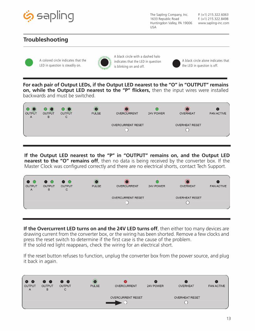
For each pair of Output LEDs, if the Output LED nearest to the “O” in “OUTPUT” remains on, while the Output LED nearest to the “P” flickers, then the input wires were installed backwards and must be switched.
A colored circle indicates that the LED in question is steadily on.
A black circle with a dashed halo indicates that the LED in question is blinking on and off.
A black circle alone indicates that the LED in question is off.
If the Output LED nearest to the “P” in “OUTPUT” remains on, and the Output LED nearest to the “O” remains off, then no data is being received by the converter box. If the Master Clock was configured correctly and there are no electrical shorts, contact Tech Support.
If the Overcurrent LED turns on and the 24V LED turns off, then either too many devices are drawing current from the converter box, or the wiring has been shorted. Remove a few clocks and press the reset switch to determine if the first case is the cause of the problem. If the solid red light reappears, check the wiring for an electrical short.
If the reset button refuses to function, unplug the converter box from the power source, and plug it back in again.
The Sapling Company, Inc.1633 Republic RoadHuntingdon Valley, PA 19006USA
P. (+1) 215.322.6063F. (+1) 215.322.8498www.sapling-inc.com
14
Troubleshooting (continued)
If all of the LEDs are functioning normally, but a time signal is not reaching your clocks, check the wiring between the converter box and the clocks. If the wiring is sound, compare the number and position of the clocks you installed to the “Converter Box Table” at the beginning of this manual.
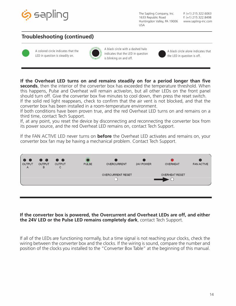
If the Overheat LED turns on and remains steadily on for a period longer than five seconds, then the interior of the converter box has exceeded the temperature threshold. When this happens, Pulse and Overheat will remain active/on, but all other LEDs on the front panel should turn off. Give the converter box five minutes to cool down, then press the reset switch. If the solid red light reappears, check to confirm that the air vent is not blocked, and that the converter box has been installed in a room-temperature environment. If both conditions have been proven true, and the red Overheat LED turns on and remains on a third time, contact Tech Support. If, at any point, you reset the device by disconnecting and reconnecting the converter box from its power source, and the red Overheat LED remains on, contact Tech Support.
If the FAN ACTIVE LED never turns on before the Overheat LED activates and remains on, your converter box fan may be having a mechanical problem. Contact Tech Support.
If the converter box is powered, the Overcurrent and Overheat LEDs are off, and either the 24V LED or the Pulse LED remains completely dark, contact Tech Support.
A colored circle indicates that the LED in question is steadily on.
A black circle with a dashed halo indicates that the LED in question is blinking on and off.
A black circle alone indicates that the LED in question is off.

The Sapling Company, Inc.1633 Republic RoadHuntingdon Valley, PA 19006USA
P. (+1) 215.322.6063F. (+1) 215.322.8498www.sapling-inc.com
15
Warranty
Sapling Limited Warranty and DisclaimerThe Sapling Company, Inc. warrants only that at the time of delivery and for a period of 24 calendar months after delivery or the period stated in this invoice, if different, the Goods shall be free of defects in workmanship and materials, PROVIDED that this warranty shall not apply:
To damage caused by Buyer’s or any third party’s act, default or misuse of the Goods or by failure to follow any instructions supplied with the Goods.
Where the Goods have been used in connection with or incorporated into equipment or materials the specification of which has not been approved in writing by The Sapling Company, Inc.;
To Goods which are altered, modified or repaired in any place other than a Sapling Company, Inc. factory or by persons not expressly authorized or approved in writing by The Sapling Company, Inc.
THE FOREGOING WARRANTY IS EXCLUSIVE AND IN LIEU OF ALL OTHER WARRANTIES WITH RESPECT TO GOODS DELIVERED UNDER THIS CONTRACT, WHETHER EXPRESS OR IMPLIED, INCLUDING WITHOUT LIMITATION, ANY IMPLIED WARRANTY OF MERCHANTABILITY OR FITNESS FOR A PARTICULAR PURPOSE. The foregoing warranty runs only to Buyer. There are no oral or written promises, representations or warranties collateral to or affecting this contract. Representatives of The Sapling Company, Inc. may have made oral statements about products described in this contract. Such statements do not constitute warranties, shall not be relied on by Buyer and are not part of the contract.
Note: An extended 5 year (60 month) warranty is also available at the time of the system purchase with a surcharge.