sara 006:2012 edition 1 - sara rail · sara 006:2012 edition 1. sheet 9.6 — w361-electrical-shock...
TRANSCRIPT
SARA 006:2012 Edition 1
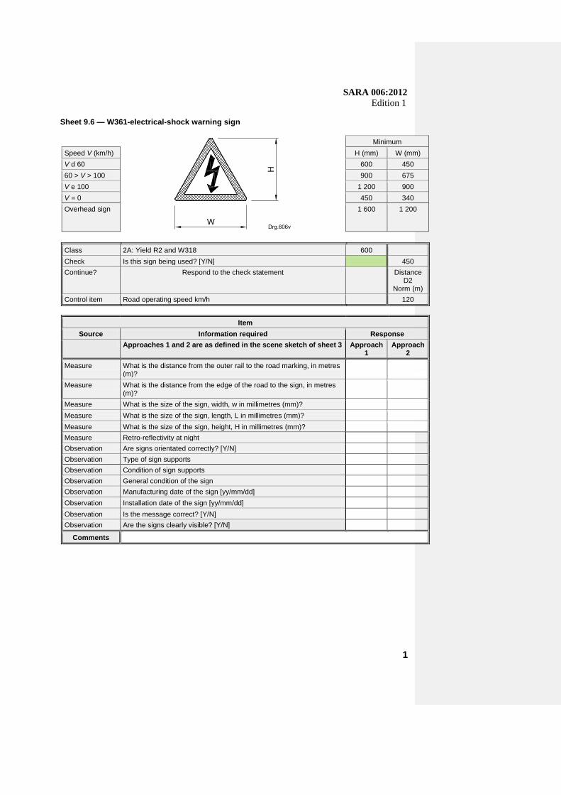
Sheet 9.6 — W361-electrical-shock warning sign
Minimum
Speed V (km/h) H (mm) W (mm)
V d 60 600 450
60 > V > 100 900 675
V e 100 1 200 900
V = 0 450 340
Overhead sign 1 600 1 200
Class 2A: Yield R2 and W318 600
Check Is this sign being used? [Y/N] 450
Continue? Respond to the check statement Distance D2
Norm (m)
Control item Road operating speed km/h 120
Item
Source Information required Response
Approaches 1 and 2 are as defined in the scene sketch of sheet 3 Approach 1
Approach 2
Measure What is the distance from the outer rail to the road marking, in metres (m)?
Measure What is the distance from the edge of the road to the sign, in metres (m)?
Measure What is the size of the sign, width, w in millimetres (mm)?
Measure What is the size of the sign, length, L in millimetres (mm)?
Measure What is the size of the sign, height, H in millimetres (mm)?
Measure Retro-reflectivity at night
Observation Are signs orientated correctly? [Y/N]
Observation Type of sign supports
Observation Condition of sign supports
Observation General condition of the sign
Observation Manufacturing date of the sign [yy/mm/dd]
Observation Installation date of the sign [yy/mm/dd]
Observation Is the message correct? [Y/N]
Observation Are the signs clearly visible? [Y/N]
Comments
1

SARA 006:2012 Edition 1
Sheet 9.7 — W403/W404 railway crossing
Minimum
Speed V (km/h) H (mm) W (mm)
V d 60 600 450
60 > V > 100 900 675
V e 100 1 200 900
V = 0 450 340
Overhead sign 1 600 1 200
Class 2A: Yield R2 and W318 600
Check Is this sign being used? [Y/N] 450
Continue? Respond to the check statement Distance D2
Norm (m)
Control item Road operating speed km/h 120
Item
Source Information required Response
Approaches 1 and 2 are as defined in the scene sketch of sheet 3 Approach 1
Approach 2
Measure What is the distance from the outer rail to the road marking, in metres (m)?
Measure What is the distance from the edge of the road to the sign, in metres (m)?
Measure What is the size of the sign, width, w in millimetres (mm)?
Measure What is the size of the sign, length, L in millimetres (mm)?
Measure What is the size of the sign, height, H in millimetres (mm)?
Measure Retro-reflectivity at night
Observation Are signs orientated correctly? [Y/N]
Observation Type of sign supports
Observation Condition of sign supports
Observation General condition of the sign
Observation Manufacturing date of the sign [yy/mm/dd]
Observation Installation date of the sign [yy/mm/dd]
Observation Is the message correct? [Y/N]
Observation Are the signs clearly visible? [Y/N]
Comments

SARA 006:2012 Edition 1
Sheet 9.8 — IN11 supplementary plates
Minimum
Speed V (km/h) H (mm) W (mm)
V d 60 600 450
60 > V > 100 900 675
V e 100 1 200 900
V = 0 450 340
Overhead sign 1 600 1 200
Class 2A: Yield R2 and W318 600
Check Are any of these signs being used? [Y/N] 450
Continue? Respond to the check statement Distance D2
Norm (m)
Control item Road operating speed km/h 120
Item
Source Information required Response
Approaches 1 and 2 are as defined in the scene sketch of sheet 3 Approach 1
Approach 2
Measure What is the distance from the outer rail to the road marking, in metres (m)?
Measure What is the distance from the edge of the road to the sign, in metres (m)?
Measure What is the size of the sign, width, w in millimetres (mm)?
Measure What is the size of the sign, length, L in millimetres (mm)
Measure What is the size of the sign, height, H in (mm)?
Measure Retro-reflectivity at night
Observation Are signs orientated correctly? [Y/N]
Observation Type of sign supports
Observation Condition of sign supports
Observation General condition of the sign
Observation Manufacturing date of the sign [yy/mm/dd]
Observation Installation date of the sign [yy/mm/dd]
Observation Is the message correct? [Y/N]
Comments

SARA 006:2012 Edition 1
Sheet 9.9 — GS901 diagrammatic sign
Minimum
Speed V (km/h) H (mm) W (mm)
V d 60 600 450
60 > V > 100 900 675
V e 100 1 200 900
V = 0 450 340
Overhead sign 1 600 1 200
Class 2A: Yield R2 and W318 600
Check Is this sign being used? [Y / N] 450
Continue? Respond to the check statement Distance D2
Norm (m)
Control item Road operating speed km/h 120
Item
Source Information required Response
Approaches 1 and 2 are as defined in the scene sketch of sheet 3 Approach 1
Approach 2
Measure What is the distance from the outer rail to the road marking, in metres (m)?
0 0
Measure What is the distance from the edge of the road to the sign, in metres (m)?
0 0
Measure What is the size of the sign, width, w in millimetres (mm)? 0 0
Measure What is the size of the sign, length, L in (mm)? 0 0
Measure What is the size of the sign, height, H in millimetres (mm)? 0 0
Measure Retro-reflectivity at night
Observation Are signs orientated correctly? [Y/N]
Observation Type of sign supports
Observation Condition of sign supports
Observation General condition of the sign
Observation Manufacturing date of the sign [yy/mm/dd]
Observation Installation date of the sign [yy/mm/dd]
Observation Is the message correct? [Y/N]
Comments
SARA 006:2012 Edition 1
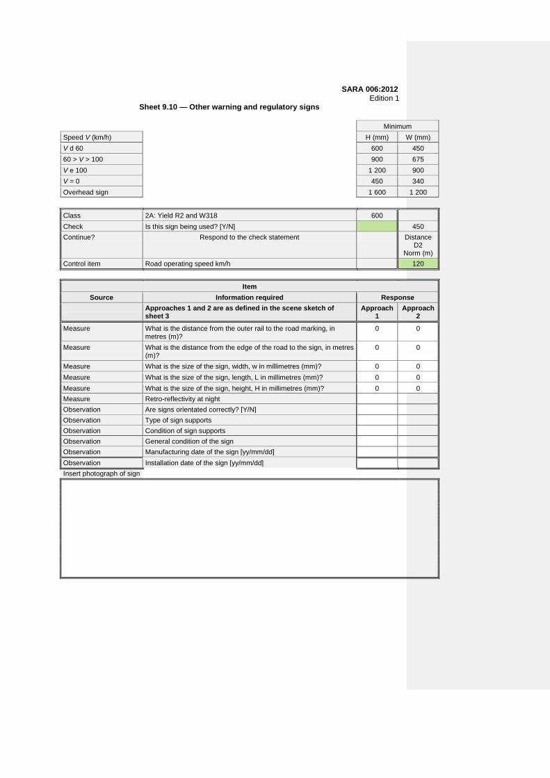
Sheet 9.10 — Other warning and regulatory signs
Minimum
Speed V (km/h) H (mm) W (mm)
V d 60 600 450
60 > V > 100 900 675
V e 100 1 200 900
V = 0 450 340
Overhead sign 1 600 1 200
Class 2A: Yield R2 and W318 600
Check Is this sign being used? [Y/N] 450
Continue? Respond to the check statement Distance D2
Norm (m)
Control item Road operating speed km/h 120
Item
Source Information required Response
Approaches 1 and 2 are as defined in the scene sketch of sheet 3
Approach 1
Approach 2
Measure What is the distance from the outer rail to the road marking, in metres (m)?
0 0
Measure What is the distance from the edge of the road to the sign, in metres (m)?
0 0
Measure What is the size of the sign, width, w in millimetres (mm)? 0 0
Measure What is the size of the sign, length, L in millimetres (mm)? 0 0
Measure What is the size of the sign, height, H in millimetres (mm)? 0 0
Measure Retro-reflectivity at night
Observation Are signs orientated correctly? [Y/N]
Observation Type of sign supports
Observation Condition of sign supports
Observation General condition of the sign
Observation Manufacturing date of the sign [yy/mm/dd]
Observation Installation date of the sign [yy/mm/dd]
Insert photograph of sign

SARA 006:2012 Edition 1
Sheet 10 — WM1 road surface sign
Speed V (km/h)
C1 C2
120 250 400
100 180 300
80 125 200
60 90 150
40 90 150
Class 2A: Yield R2 and W318 600
Check Is this sign being used? [Y/N] 450
Continue? Respond to the check statement C1 90
Control item Road operating speed km/h 60
C2 150
Item
Source Information required Response
Approaches 1 and 2 are as defined in the scene sketch of sheet 3
Approach 1
Approach 2
Measure What is the distance from the outer rail to the road marking, C1, in metres (m)?
Measure What is the distance from the outer rail to the road marking, C2, in metres (m)?
Measure What is the size of the marking, width, W in above sketch in millimetres (mm)?
Measure What is the size of the marking, length, H in above sketch in millimetres (mm)?
Observation General condition of the markings
Observation Are the centre lines/lane markings present? [Y/N]
Observation Is the sign in the middle of the road lane? [Y/N]
Measure Retro-reflectivity at night
Comments
SARA 006:2012 Edition 1
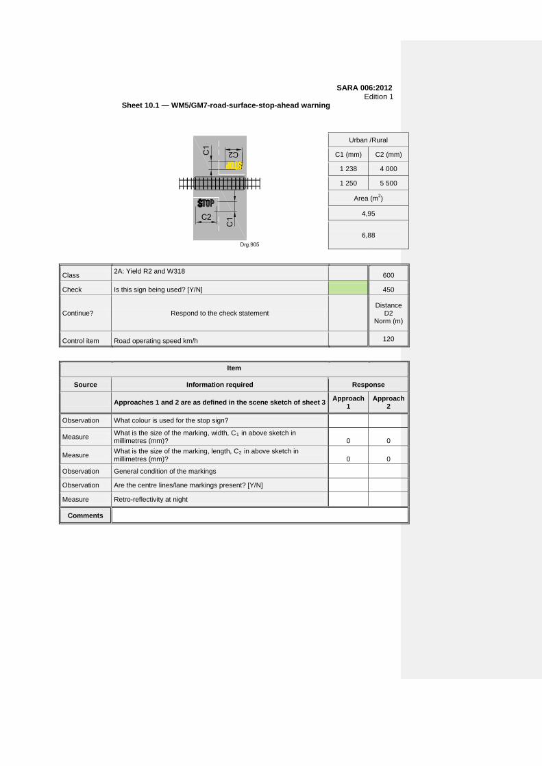
Sheet 10.1 — WM5/GM7-road-surface-stop-ahead warning
Urban /Rural
C1 (mm) C2 (mm)
1 238 4 000
1 250 5 500
Area (m2)
4,95
6,88
Class 2A: Yield R2 and W318
600
Check Is this sign being used? [Y/N] 450
Continue? Respond to the check statement
Distance D2
Norm (m)
Control item Road operating speed km/h 120
Item
Source Information required Response
Approaches 1 and 2 are as defined in the scene sketch of sheet 3 Approach 1
Approach 2
Observation What colour is used for the stop sign?
Measure What is the size of the marking, width, C1 in above sketch in millimetres (mm)? 0 0
Measure What is the size of the marking, length, C2 in above sketch in millimetres (mm)? 0 0
Observation General condition of the markings
Observation Are the centre lines/lane markings present? [Y/N]
Measure Retro-reflectivity at night
Comments

SARA 006:2012 Edition 1
Sheet 11 — Flashing red disk signals
Minimum
Speed V (km/h) H (mm) W (mm)
V d 60 600 450
60 > V > 100 900 675
V e 100 1 200 900
V = 0 450 340
Overhead sign 1 600 1 200
Class 2A: Yield R2 and W318 600
Check Is this sign being used? [Y/N] 450
Continue? Respond to the check statement Distance D2
Norm (m)
Control item Road operating speed km/h 120
Item
Source Information required Response
Approaches 1 and 2 are as defined in the scene sketch of sheet 3
Approach 1 Approach 2
Measure What is the distance from the outer rail to the road marking, in metres (m)?
Measure What is the distance from the edge of the road to the sign, in metres (m)?
Measure What is the size of the sign, width, w in millimetres (mm)?]
Measure What is the size of the sign, length, L in millimetres (mm)?
Measure What is the size of the sign, height, H in millimetres (mm)?
Measure Retro-reflectivity at night
Measure Advance warning, in seconds (s). for approaching trains
Observation Approach 1 – alignment of signal correct [Y/N]
Observation Type of signal support
Observation Condition of the signal supports
Observation Is the system working effectively? [Y/N]
Observation Manufacturing date of the sign [yy/mm/dd]
Observation Installation date of the sign [yy/mm/dd]
Measure Clearance time of rail traffic before light stops, in seconds (s)
Comments
SARA 006:2012 Edition 1
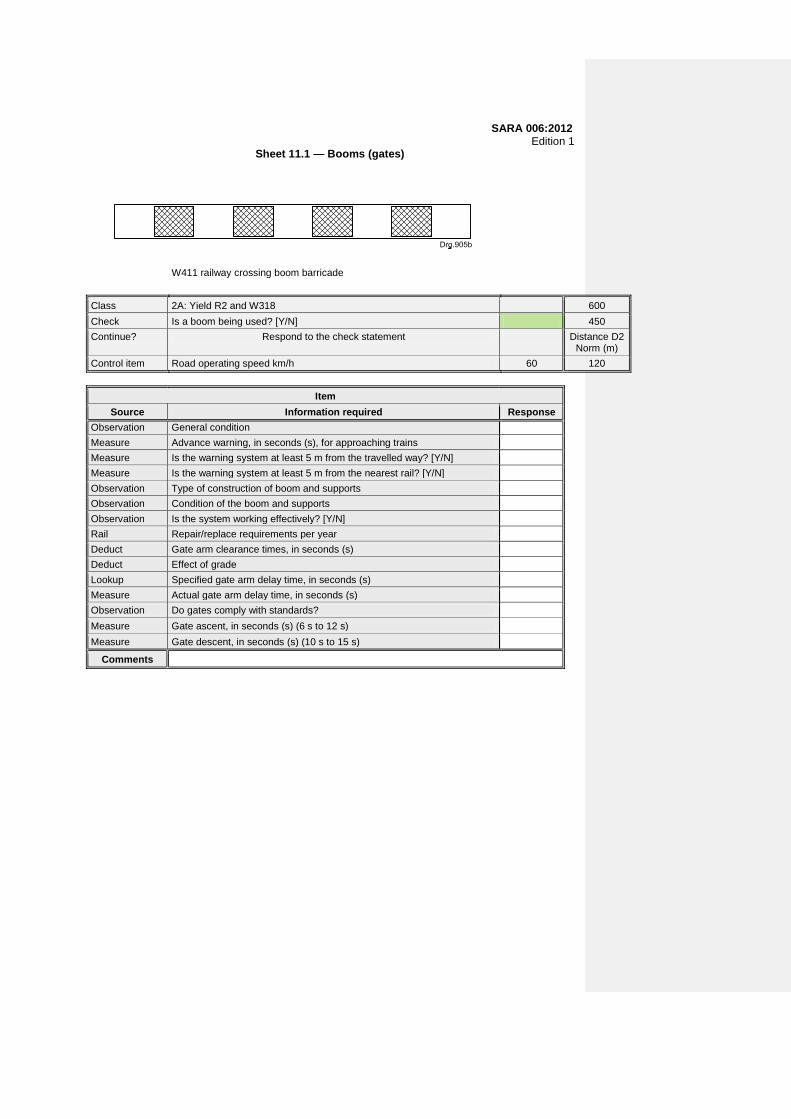
Sheet 11.1 — Booms (gates)
W411 railway crossing boom barricade
Class 2A: Yield R2 and W318 600
Check Is a boom being used? [Y/N] 450
Continue? Respond to the check statement Distance D2 Norm (m)
Control item Road operating speed km/h 60 120
Item
Source Information required Response
Observation General condition
Measure Advance warning, in seconds (s), for approaching trains
Measure Is the warning system at least 5 m from the travelled way? [Y/N]
Measure Is the warning system at least 5 m from the nearest rail? [Y/N]
Observation Type of construction of boom and supports
Observation Condition of the boom and supports
Observation Is the system working effectively? [Y/N]
Rail Repair/replace requirements per year
Deduct Gate arm clearance times, in seconds (s)
Deduct Effect of grade
Lookup Specified gate arm delay time, in seconds (s)
Measure Actual gate arm delay time, in seconds (s)
Observation Do gates comply with standards?
Measure Gate ascent, in seconds (s) (6 s to 12 s)
Measure Gate descent, in seconds (s) (10 s to 15 s)
Comments

SARA 006:2012 Edition 1
Sheet 11.2 — Flashing yellow warning lights
Minimum
Speed V (km/h)
H (mm) W (mm)
V d 60 600 450
60 > V > 100 900 675
V e 100 1 200 900
V = 0 450 340
Overhead sign 1 600 1 200
Class 2A: Yield R2 and W318 600
Check Is this sign being used? [Y/N] 450
Continue? Respond to the check statement Distance D2
Norm (m)
Control item Road operating speed km/h 120
Item
Source Information required Approach 1
Approach 2
Measure What is the distance from the outer rail to the road marking, in metres (m)?
Measure What is the distance from the edge of the road to the sign, in metres (m)?
Measure What is the size of the sign, width, w in millimetres (mm)?
Measure What is the size of the sign, length, L in millimetres (mm)?
Measure What is the size of the sign, height, H in millimetres (mm)
Measure Retro-reflectivity at night
Observation Condition of sign support
Observation Is the system (lights) working effectively? [Y/N]
Observation Approach 1 – are the lights aligned correctly? [Y/N]
Observation Approach 2 – are the lights aligned correctly? [Y/N]
Observation Type of sign support
Observation Condition of sign support
Observation With which warning sign is the lights installed?
Comments

SARA 006:2012 Edition 1
Sheet 11.3 — Bells
Item
Source Information required Response
Observation General condition
Measure Advance warning, in seconds (s), for approaching trains
Measure Is the warning system at least 8 m from the travelled way? [Y/N]
Measure Is the warning system at least 8 m from the nearest rail? [Y/N]
Observation Type of construction housing the system
Observation Condition of the construction
Observation Is the system working effectively? [Y/N]
Comments

SARA 006:2012 Edition 1
Sheet 11.4 — Traffic signal
Minimum
Speed V (km/h)
H (mm) W (mm)
V d 60 600 450
60 > V > 100 900 675
V e 100 1 200 900
V = 0 450 340
Overhead sign 1 600 1 200
Class 600
Check Is this sign being used? [Y/N] 450
Continue? Respond to the check statement Distance D2
Norm (m)
Control item Road operating speed km/h 120
Item
Source Information required Approach 1
Approach 2
Measure What is the distance from the outer rail to the road marking, in metres (m)?
Measure What is the distance from the edge of the road to the sign, in metres (m)?
Measure What is the size of the sign, width, w in millimetres (mm)?
Measure What is the size of the sign, length, L in millimetres (mm)?
Measure What is the size of the sign, height, H in millimetres (mm)?
Measure Retro-reflectivity at night
Observation Condition of sign support
Observation Is the system (lights) working effectively? [Y/N]
Observation Approach 1 – are the lights aligned correctly? [Y/N]
Observation Approach 2 – are the lights aligned correctly? [Y/N]
Observation Type of sign support
Observation Condition of sign support
Observation With which warning sign is the lights installed?
Comments
SARA 006:2012 Edition 1
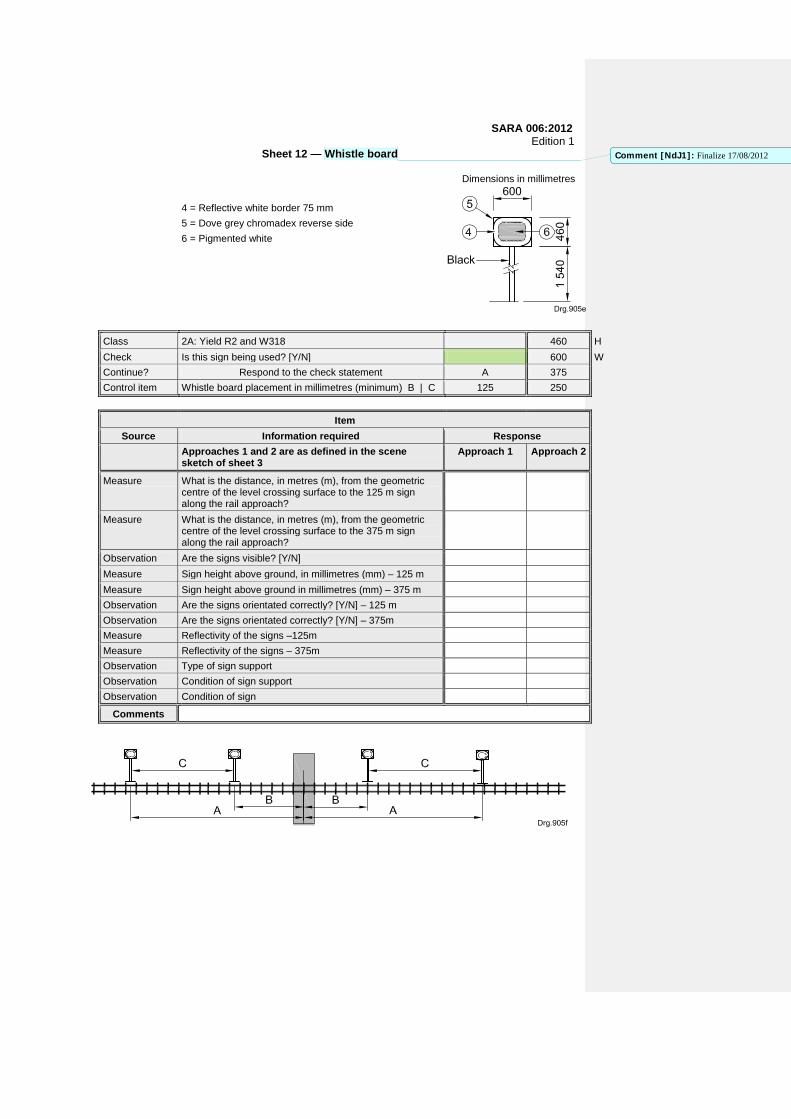
Sheet 12 — Whistle board
Dimensions in millimetres
4 = Reflective white border 75 mm
5 = Dove grey chromadex reverse side
6 = Pigmented white
Class 2A: Yield R2 and W318 460 H
Check Is this sign being used? [Y/N] 600 W
Continue? Respond to the check statement A 375
Control item Whistle board placement in millimetres (minimum) B | C 125 250
Item
Source Information required Response
Approaches 1 and 2 are as defined in the scene sketch of sheet 3
Approach 1 Approach 2
Measure What is the distance, in metres (m), from the geometric centre of the level crossing surface to the 125 m sign along the rail approach?
Measure What is the distance, in metres (m), from the geometric centre of the level crossing surface to the 375 m sign along the rail approach?
Observation Are the signs visible? [Y/N]
Measure Sign height above ground, in millimetres (mm) – 125 m
Measure Sign height above ground in millimetres (mm) – 375 m
Observation Are the signs orientated correctly? [Y/N] – 125 m
Observation Are the signs orientated correctly? [Y/N] – 375m
Measure Reflectivity of the signs –125m
Measure Reflectivity of the signs – 375m
Observation Type of sign support
Observation Condition of sign support
Observation Condition of sign
Comments
Comment [NdJ1]: Finalize 17/08/2012
SARA 006:2012 Edition 1
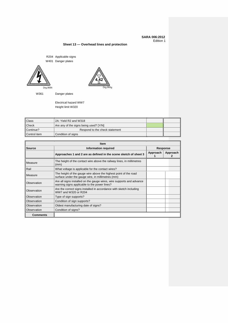
Sheet 13 — Overhead lines and protection
R204 Applicable signs
W401 Danger plates
W361
Danger plates
Electrical hazard WW7
Height limit W320
Class 2A: Yield R2 and W318
Check Are any of the signs being used? [Y/N]
Continue? Respond to the check statement
Control item Condition of signs
Item
Source Information required Response
Approaches 1 and 2 are as defined in the scene sketch of sheet 3 Approach 1
Approach 2
Measure The height of the contact wire above the railway lines, in millimetres (mm)
Rail What voltage is applicable for the contact wires?
Measure The height of the gauge wire above the highest point of the road surface under the gauge wire, in millimetres (mm)
Observation Are all signs installed on the gauge wires, wire supports and advance warning signs applicable to the power lines?
Observation Are the correct signs installed in accordance with sketch including WW7 and W320 or R204
Observation Type of sign supports?
Observation Condition of sign supports?
Observation Oldest manufacturing date of signs?
Observation Condition of signs?
Comments
SARA 006:2012 Edition 1
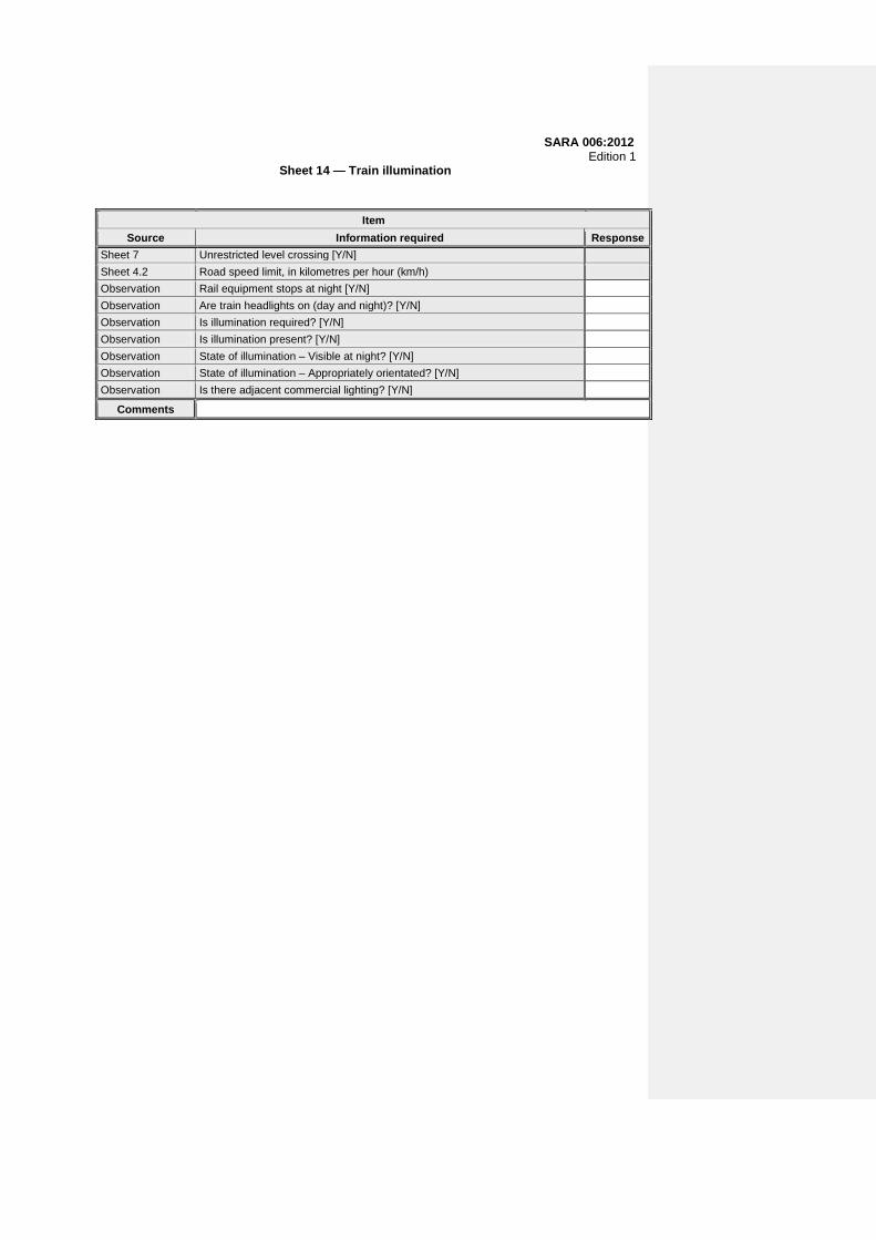
Sheet 14 — Train illumination
Item
Source Information required Response
Sheet 7 Unrestricted level crossing [Y/N]
Sheet 4.2 Road speed limit, in kilometres per hour (km/h)
Observation Rail equipment stops at night [Y/N]
Observation Are train headlights on (day and night)? [Y/N]
Observation Is illumination required? [Y/N]
Observation Is illumination present? [Y/N]
Observation State of illumination – Visible at night? [Y/N]
Observation State of illumination – Appropriately orientated? [Y/N]
Observation Is there adjacent commercial lighting? [Y/N]
Comments

SARA 006:2012 Edition 1
Annex B (normative)
Risk assessment methodology
B.1 General B.1.1 Processes and procedures shall be established, developed or adopted, documented and maintained to identify, estimate, evaluate and prioritize risks by means of a formal risk assessment method to reduce the hazards and risks at level crossings. B.1.2 A risk assessment shall be conducted after any physical assessment of level crossings. B.1.3 Processes and procedures shall be established, developed or adopted, documented and maintained to compile and implement formal risk control strategies for risks classified as unacceptable or tolerable with mitigation. B.1.4 This methodology applies throughout the life-cycle phases as described in 4.4.2 and SARA 002. B.1.5 Particular focus shall be placed on hazards that impact on safe operations at level crossings as identified during the assessment. Particular focus shall also be placed on issues related to human factors and the management of the interfaces between network operators (RAs) and road authorities. B.1.6 Existing risk controls are based on historically developed and reviewed standards, specifications, guidelines, procedures, rules and regulations. A complete risk assessment of existing controls is required after a physical assessment has been conducted as described in 5.1 and 5.2. B.1.7 Risk assessments shall be conducted jointly by the network operator (RA) and the relevant road authority at least once every five years, unless a) the parties agree at the time of the risk assessment to extend the deadline for the next
assessment from five years to a maximum of 10 years, and b) the parties provide reasons for concluding that the safety conditions will remain stable for the
extended period. B.2 Risk assessment process B.2.1 The objective of this risk assessment process is the successful management of identified hazards. It is aimed at protecting the level crossing user, network operator (RA) or road authority (or both), or persons close to the level crossing, against adverse consequences of exposure to risk, by reducing the probability and severity of undesired events (i.e. loss-producing events). B.2.2 The focus when managing risk shall be on preventive/proactive measures. B.2.3 Formal operational risk assessments shall be conducted by network operators and road authorities in accordance with this procedure. B.3 Hazard identification B.3.1 The first and most critical step in the management of risk is hazard identification. The presence of a hazard brings forth a risk associated with that particular hazard.
SARA 006:2012 Edition 1 B.3.2 The following shall be used as input to identify hazards in existing RAs: a) assessments of level crossings; b) occurrence investigations; c) collection and analysis of safety performance data; d) inspections; and e) safety audits. B.3.3 The following shall be used as input to identify hazards in proposed new level crossings: a) exclusion criteria; b) the application; c) assessments of level crossings; and d) SADCRTSM B.3.4 A hazard is any event that can cause damage, injury, death (i.e. a loss-producing event). Alternatively, it is any condition or action with the potential to cause harm. B.3.5 Risk is the presence of uncertainty in a situation and has dimensions relating to exposure, probability and severity. Example: A hazard might exist, but it is not certain whether it will result in a loss-producing event or not. The associated risk is a measure of this uncertainty and is determined by a risk matrix, which considers the exposure to the hazard, probability of a loss-producing event and the severity of the consequences when a loss-producing event takes place. B.3.6 Hazard identification is a systematic process of establishing what can go wrong (cause) and what loss could be caused (consequence). B.3.7 There are various hazard identification methodologies and a combination of the following techniques is most useful: a) brainstorming; and b) the structured what-if technique (SWIFT). B.3.8 Brainstorming relies on the knowledge and experience of employees within the organization. It is also useful in that anyone can be involved in the process based on their expertise in the particular area. B.3.9 The SWIFT method relies on asking the question “What if?” to establish what could go wrong and what the consequence would be. This process proactively results in a set of hazards that has to be managed. B.3.10 Hazards shall be identified in the railway and road operating environment at level crossings, specifically the potential impact they might have on railway safety and level crossing users or persons close to the level crossing. Identifying hazards is most easily done by answering the question: “What possibly can go wrong in the operations that could cause harm (injury/death/damage) to railway or road users or persons within the operational area at level crossings?” B.4 Risk analysis
SARA 006:2012 Edition 1 NOTE A risk analysis is a process where hazards are quantified and ranked relative to one another. Hazards are ranked to determine management priorities and resource allocation. B.4.1 Risk estimation and quantification B.4.1.1 Having identified all hazards, they have to be put into perspective in terms of knowing the extent of each. In order to deal with hazards in priority, the risk associated with each hazard shall be quantitatively estimated. B.4.1.2 Risk consists of exposure, probability (likelihood) and severity (consequence). Only once these three elements have been established, the risk can be estimated. The following formula can be used: Risk estimation = exposure × probability × severity B.4.1.3 Exposure is the frequency of the occurrence of the hazard (or hazardous event). Example: If the ignorance of a train driver to sound the train's whistle is the identified hazard, then what is the frequency with which trains are running without train drivers blowing the whistle at level crossings? A continuous rating (10) would mean that at any time of operation there is at least one train that runs without the train driver sounding the train's whistle. B.4.1.4 Probability is the frequency of a loss-producing event when the hazard (or hazardous event) occurs. Example: If there is a train running without the train driver blowing the train's whistle at level crossings or when the train driver saw people next to or near the railway lines (hazard), what is the frequency in which an occurrence vehicle had been struck (occurrence) or in which people had been injured/run over (loss-producing event) resulting from the train driver failing to sound the whistle. An alternative term for probability that is used often is likelihood. B.4.1.5 Severity is the loss that results from a loss-producing event (for example an accident, occurrence or death). Example: When a train driver does not blow the train's whistle (hazard), an occurrence might happen (vehicle might be struck or people might be injured/run over) (loss-producing event) from the train resulting in fatal injuries (loss). An alternative term for severity that is used often is consequences. B.4.1.6 In practically applying the above definitions the following serve as guidelines to a team of functional experts to quantify the risk: a) Exposure is that portion of time (out of the total time of operation) where the hazard is present.
It is simple when the exposure is at most once a week. However, it is somewhat difficult to decide between daily and continuous exposure. It is again simple when the operation consists of only one activity at a time. For example, if there is only one train running at any given time of operations (albeit that it might be different trains), then a continuous rating would mean that the particular hazard exists all the time. If not, the rating is daily.
Now, consider that there might be multiple trains running at any given time, the chances that one of those trains has the hazard present is greater than when only a single train runs at that given time. Taken over the total time of operations in the day, it might well be expected that at least one of the trains at any moment has the hazard present, which would then imply that the exposure is continuous. Perhaps the easiest way to determine if a rating is continuous is to divide the day into time frames (say hours) and to determine in each time frame what is the frequency of occurrence of the hazard. If the frequency of occurrence is one or more in all the time frames, then the rating is continuous, otherwise it is daily. This need not be an intense data driven process but rather one that is guided by the experience of the team supported by some operational data. If there is doubt or the process tends to be laborious, the higher rating should be chosen.
b) The probability is determined by looking at the history of loss-producing events. Should no
history be available on a newly identified hazard, discretion shall be used by the team, siding with the higher rating should there be doubt. Occurrence recording from there onwards will
SARA 006:2012 Edition 1
indicate if the probability score was reasonable. In the case where history was not available, occurrence recording over the next three months has to inform a review of the probability score.
c) The severity is determined by the team using past consequences or discretion. In all cases the
worst-case scenario (whilst still remaining realistic) shall be chosen. B.4.2 Risk evaluation B.4.2.1 Once the risk has been quantified, the decision has to be made whether the risk is acceptable or not. B.4.2.2 All risks shall be classified into one of the following three categories: a) Tolerable – the level of risk is acceptable and no special or additional strategy is required to
mitigate the risk. b) Tolerable with mitigation – the as-low-as-reasonably-practical principle (ALARP) will guide the
strategies to reduce the risk to an acceptable level. c) Unacceptable – the level of risk is unacceptably high and strategies to reduce the risk shall be
applied. B.4.2.3 Reducing the exposure, probability or severity or any combination of the three can reduce the risk. The objective is to implement control measures in order to mitigate all risks into the tolerable segment of the matrix. B.4.3 Risk ranking B.4.3.1 Risks are ranked from the highest to the lowest according to the overall risk as determined above. This ranking will guide the network operator and road authority in decisions regarding priorities and resource allocation. It is important to note that the ranking is dynamic and dependent on progress made in addressing the identified risk control strategies or regressions detected during audits or performance analyses. B.4.3.2 The procedures for risk assessments and resultant risk profiles shall be reviewed a) periodically (at least every five years), b) after a major occurrence, c) when the safety performance does not improve, and d) in accordance with any directive issued by the relevant national railway safety regulator (see
foreword). B.4.3.3 Risks are quantified and prioritized using the hazard identification and risk assessment schedule as given in table B.1. B.5 Risk control B.5.1 Risk control measures shall be developed and documented once hazards have been identified and the associated risks quantified. B.5.2 These measures shall focus on and include the following: a) eliminating the situation, object, condition or activity that generates the risk, thereby reducing
the exposure; b) reducing the probability of an occurrence; and

SARA 006:2012 Edition 1 c) reducing the severity of the occurrence (consequences). B.5.3 As outlined in the sections on risk estimation and evaluation, each hazard is plotted on the risk matrix. Based on this, risks are categorized in terms of unacceptable (red) or tolerable with mitigation (orange/yellow), and control measures shall be developed until the risks fall within the tolerable (green) area. B.5.4 In cases where the residual risk at a level crossing is unacceptably high after applying the maximum level of protection described in clause 17 and annex C, the level crossing shall be listed for decommissioning by means of a structure, or, where possible, shall be closed. B.5.5 Risk control measures shall be developed and documented for each hazard and shall also form part of the annual safety improvement plan. B.5.6 Risk control measures shall be communicated to relevant parties including employees and members of the public and shall be implemented to address risk exposure.

SARA 006:2012 Edition 1
SA
NS
3000-2-2-1:2012 E
dition 1
Table B.1 — Risk assessment of level crossings
1 2 3 4 5 6 7 8 9
Control reference Hazard log
Numerical risk ratings Rating Control measures to minimize risks at
level crossing
Numerical risk
ratings Rating Risk
reduction %
Target date
E P S Sc E P S Sc
1 0 0 0 Low 0 0 0 0 Low #DIV/0!
2 0 0 0 0 Low 0 0 0 0 Low #DIV/0!
3 0 0 0 0 Low 0 0 0 0 Low #DIV/0!
4 0 0 0 0 Low 0 0 0 0 Low #DIV/0!
5 0 0 0 0 Low 0 0 0 0 Low #DIV/0!
6 0 0 0 0 Low 0 0 0 0 Low #DIV/0!
7 0 0 0 Low 0 0 0 0 Low #DIV/0!
8 0 0 0 0 Low 0 0 0 0 Low #DIV/0!
9 0 0 0 0 Low 0 0 0 0 Low #DIV/0!
10 0 0 0 0 Low 0 0 0 0 Low #DIV/0!
11 0 0 0 0 Low 0 0 0 0 Low #DIV/0!
12 0 0 0 0 Low 0 0 0 0 Low #DIV/0!
13 0 0 0 0 Low 0 0 0 0 Low #DIV/0!
14 0 0 0 0 Low 0 0 0 0 Low #DIV/0!
15 0 0 0 0 Low 0 0 0 0 Low #DIV/0!
93
21

SANS 3000-2-2-1:2012 Edition 1
Figure B.1 — Risk matrix
22

SARA 006:2012 Edition 1
Annex C (normative)
Signage for level crossings
C.1 General C.1.1 Processes and procedures shall be established, developed or adopted, implemented and maintained by road authorities and network operators (RAs) to ensure that road traffic signs, i.e. road signs, road markings and traffic signals, are used collectively at level crossings. C.1.2 A range of circumstances might affect the level of signage at level crossings. The most relevant factor is the level of the prevailing risk at the level crossing and how it is addressed. Additional factors are listed in 5.1 and 5.2. C.1.3 Owing to the extremely high risk of fatalities and serious injuries in an occurrence between a road vehicle and a train, the objective of road authorities and network operators (RAs) shall be to achieve the highest measure of conformity with standard signage practices at level crossings, as well as their maintenance standards. C.1.4 The following figures are given in this annex: a) Figure C.1: Signs, markings and signals most commonly used at level crossings. b) Figure C.2: Additional signs and sign combinations – Option 1. c) Figure C.3: Additional signs and sign combinations – Option 2. d) Figure C.4: Level crossing protection levels. e) Figure C.5: Class E or farm road level crossing. f) Figure C.6: Class C or D rural surfaced road level crossing. g) Figure C.7: Class C or D rural road level crossing on gravel road. h) Figure C.8: Class B rural road level crossing. i) Figure C.9: Overhead electrical power lines. j) Figure C.10: Low level overhead electrical power lines. k) Figure C.11: High risk level crossings. l) Figure C.12: Industrial siding level crossing. m) Figure C.13: Class B urban street level crossing – Multi-lane street. n) Figure C.14: Urban crossing of parallel railway lines. o) Figure C.15: Railway siding environments. p) Figure C.16: Local detail at a gravel road level crossing. q) Figure C.17: Local detail at a rural road surfaced level crossing. r) Figure C.18: Local detail at a boom protected road level crossing.
23

SARA 006:2012 Edition 1 s) Figure C.19: Pedestrian level crossing. t) Figure C.20: Local detail at traffic signal and boom protected level crossing. u) Figure C.21: Height gauge and display details. C.2 Protection of level crossings C.2.1 Road traffic signs provided at level crossings for the protection of road users fall in the following two categories: a) regulatory control signs, markings and signals for the control of road vehicles at level crossings, b) advance warning signs, warning signs or markings (or any combination of these) that comprise
a range of signs, which will vary according to the specific site circumstances, together with various hazard marker warning signs, for the provision of advance warning to road users approaching the level crossing.
C.2.2 Figures C.1 to C.3 show a range of appropriate signs, markings and signals that are used in various combinations according to the relative level of risk at a crossing. Classifications of the protection of and the mode of control at level crossings are defined in figure C.4. C.2.3 Train drivers shall give sufficient warning to road users when approaching a level crossing. This warning is normally given by a whistle, hooter or other sounding device. C.3 Classification of level crossings C.3.1 The following descriptions give a broad classification of the types of level crossing: a) a station/shunting yard environment; b) low speed rail traffic:
1) industrial sidings; and 2) private lines;
c) normal rail traffic – single or multiple low speed lines; and d) high speed rail traffic – single or multiple high speed lines. C.3.2 These classifications are developed into a formal classification of level crossings for purposes of establishing the required level of signage, protection and mode of control. This formal level crossing classification is detailed in table C.1. C.3.3 Modes of control and particularly the level of advance warning signage shall be upgraded to a higher level of protection (see figure C.4) according to the presence of one or more of the factors listed in 5.1 and 5.2. (See table C.2 for levels of protection.) Examples of typical level crossing situations illustrating combinations of warning signs and modes of control are given in tables C.4 and C.5.
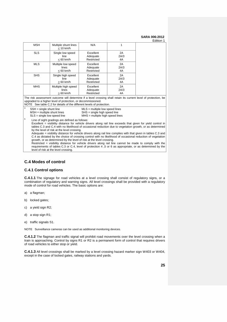
Table C.1 — Classification of level crossings
1 2 3 4 5
Classa Description Line of sightb Minimum level of protection
Recommended level of protection
SSH Single shunt line < 10 km/h
N/A 1 Risk assessment outcome dependent
SARA 006:2012 Edition 1
MSH Multiple shunt lines < 10 km/h
N/A 1
SLS Single low speed line
< 60 km/h
Excellent Adequate Restricted
2A 2A/3 4A
MLS Multiple low speed lines
< 60 km/h
Excellent Adequate Restricted
2A 2A/3 4A
SHS Single high speed line
> 60 km/h
Excellent Adequate Restricted
2A 2A/3 4A
MHS Multiple high speed lines
> 60 km/h
Excellent Adequate Restricted
2A 2A/3 4A
The risk assessment outcome will determine if a level crossing shall retain its current level of protection, be upgraded to a higher level of protection, or decommissioned. NOTE See table C.2 for details of the different levels of protection. a SSH = single shunt line MLS = multiple low speed lines
MSH = multiple shunt lines SHS = single high speed line SLS = single low speed line MHS = multiple high speed lines
b Line of sight gradings are defined as follows: Excellent = visibility distance for vehicle drivers along rail line exceeds that given for yield control in
tables C.3 and C.4 with no likelihood of occasional reduction due to vegetation growth, or as determined by the level of risk at the level crossing.
Adequate = visibility distance for vehicle drivers along rail line complies with that given in tables C.3 and C.4 as dictated by the choice of crossing control with no likelihood of occasional reduction of vegetation growth, or as determined by the level of risk at the level crossing.
Restricted = visibility distance for vehicle drivers along rail line cannot be made to comply with the requirements of tables C.3 or C.4, level of protection 4 ,5 or 6 as appropriate, or as determined by the level of risk at the level crossing.
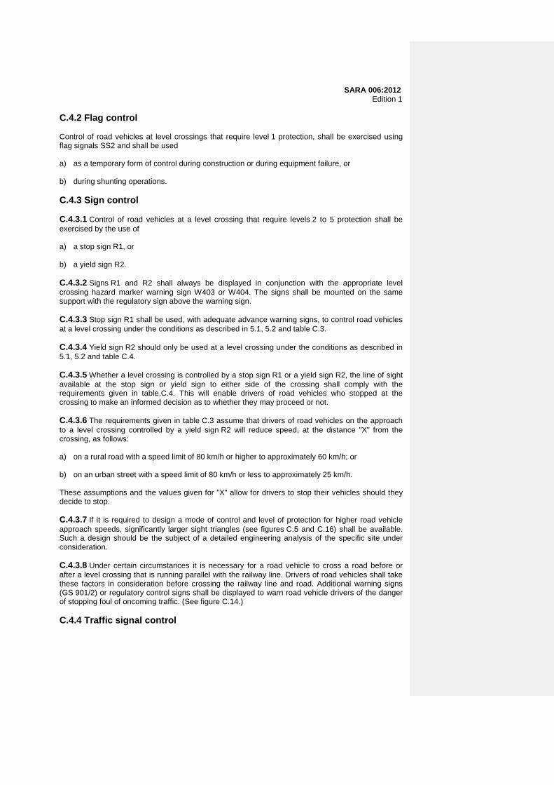
C.4 Modes of control C.4.1 Control options C.4.1.1 The signage for road vehicles at a level crossing shall consist of regulatory signs, or a combination of regulatory and warning signs. All level crossings shall be provided with a regulatory mode of control for road vehicles. The basic options are: a) a flagman; b) locked gates; c) a yield sign R2; d) a stop sign R1; e) traffic signals S1. NOTE Surveillance cameras can be used as additional monitoring devices. C.4.1.2 The flagman and traffic signal will prohibit road movements over the level crossing when a train is approaching. Control by signs R1 or R2 is a permanent form of control that requires drivers of road vehicles to either stop or yield. C.4.1.3 All level crossings shall be marked by a level crossing hazard marker sign W403 or W404, except in the case of locked gates, railway stations and yards.
25
SARA 006:2012 Edition 1 C.4.2 Flag control Control of road vehicles at level crossings that require level 1 protection, shall be exercised using flag signals SS2 and shall be used a) as a temporary form of control during construction or during equipment failure, or b) during shunting operations. C.4.3 Sign control C.4.3.1 Control of road vehicles at a level crossing that require levels 2 to 5 protection shall be exercised by the use of a) a stop sign R1, or b) a yield sign R2. C.4.3.2 Signs R1 and R2 shall always be displayed in conjunction with the appropriate level crossing hazard marker warning sign W403 or W404. The signs shall be mounted on the same support with the regulatory sign above the warning sign. C.4.3.3 Stop sign R1 shall be used, with adequate advance warning signs, to control road vehicles at a level crossing under the conditions as described in 5.1, 5.2 and table C.3. C.4.3.4 Yield sign R2 should only be used at a level crossing under the conditions as described in 5.1, 5.2 and table C.4. C.4.3.5 Whether a level crossing is controlled by a stop sign R1 or a yield sign R2, the line of sight available at the stop sign or yield sign to either side of the crossing shall comply with the requirements given in table.C.4. This will enable drivers of road vehicles who stopped at the crossing to make an informed decision as to whether they may proceed or not. C.4.3.6 The requirements given in table C.3 assume that drivers of road vehicles on the approach to a level crossing controlled by a yield sign R2 will reduce speed, at the distance "X" from the crossing, as follows: a) on a rural road with a speed limit of 80 km/h or higher to approximately 60 km/h; or b) on an urban street with a speed limit of 80 km/h or less to approximately 25 km/h. These assumptions and the values given for "X" allow for drivers to stop their vehicles should they decide to stop. C.4.3.7 If it is required to design a mode of control and level of protection for higher road vehicle approach speeds, significantly larger sight triangles (see figures C.5 and C.16) shall be available. Such a design should be the subject of a detailed engineering analysis of the specific site under consideration. C.4.3.8 Under certain circumstances it is necessary for a road vehicle to cross a road before or after a level crossing that is running parallel with the railway line. Drivers of road vehicles shall take these factors in consideration before crossing the railway line and road. Additional warning signs (GS 901/2) or regulatory control signs shall be displayed to warn road vehicle drivers of the danger of stopping foul of oncoming traffic. (See figure C.14.) C.4.4 Traffic signal control

SARA 006:2012 Edition 1 C.4.4.1 Control of road vehicles at level crossings that require levels 6A and 6B protection shall be exercised using traffic signals S1. C.4.4.2 The use of traffic signals S1 shall be in conjunction with adequate advance warning signage and shall be used to control road vehicles at a level crossing when warranted by one or more of the conditions as described in 5.1 and 5.2. C.4.4.3 If the traffic signal S1 fails, the traffic signal control reverts to that of flashing red or displaying no light. This will require all road vehicle drivers to stop. This is a fail-safe condition. The driver can then decide whether it is safe to proceed or not, as he/she would do at a stop sign R1. C.4.4.4 The installation and maintenance of traffic signals S1 shall be done in accordance with the requirements of the SADC-SARTSM. C.4.5 Boom operation C.4.5.1 Safety boom operation, either in a half-road width form or a full-road width form, shall be regarded as a high visibility hazard marker warning device and not as a form of level crossing control. Safety booms once lowered, however, also function to warn against the early release of road traffic. For additional safety, boom operation may be combined with the sounding of a loud bell or additional red lights (or both). C.4.5.2 Booms shall be lowered either manually or automatically, therefore their use is only recommended as a supplement to traffic signals S1. In exceptional circumstances booms may be used at a level crossing controlled by a stop sign R1. C.4.5.3 Steps shall be taken to ensure that road vehicle drivers do not circumvent booms and that booms do not entrap vehicles in level crossings. C.4.6 Levels of protection C.4.6.1 The various options for road traffic warning and control at level crossings are arranged in a hierarchal level of protection in table C.2 and illustrated in figure C.4. The different levels of control are linked to a level of protection in table C.1. C.4.6.2 Although levels of protection are prescribed in table C.1, the level of protection should be determined by the level of risk and in certain circumstances shall require a higher level of protection as prescribed in table C.1. This may require the decommissioning of the level crossing. C.4.6.3 The road authority responsible for providing warning signs shall take note of local conditions and shall be prepared to adjust signage or road marking positions. Some of the typical factors that might require adjustment are illustrated in figures C.6 and C.13 (see also section 1.6 of chapter 1 in vol. 1 of the SADCRTSM:1997), and are as follows: a) horizontal or vertical curvature in the approach road within the viewing distance to the warning
sign; b) obstruction by trees or other street furniture including other road traffic signs; and c) regular obscuration by other (heavy) vehicles. C.4.6.4 Figures C.5 and C.12 that show various typical level crossing situations include examples of additional measures that can be taken to enhance the effectiveness of advance warning of the crossings. The decision whether or not to use such measures should result from a detailed level crossing assessment and a risk assessment of a specific site which presumably has a worse than average accident history. Some of the signs that may be used in such circumstances are illustrated in figures C.1 to C.3.
27
SARA 006:2012 Edition 1
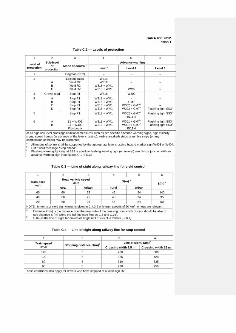
Table C.2 — Levels of protection
1 2 3 4 5 6
Level of protection
Sub-level of
protection Mode of controla
Advance warning
Level 1 Level 2 Level 3
1 Flagman (SS2) – – –
2 A B C
Locked gates Yield R2 Yield R2 Yield R2
W314 W318
W318 + WM1 W318 + WM1
– – –
WM5
– – – –
3 Gravel road Stop R1 W318 W302 –
4 A B C D
Stop R1 Stop R1 Stop R1 Stop R1
W318 + WM1 W318 + WM1 W318 + WM1 W318 + WM1
- GM7
W302 + GM7b W302 + GM7b
– – –
Flashing light SS3c
5 Stop R1
W318 + WM1 W302 + GM7b IN11.4
Flashing light SS3c
6 A B
S1 + W403 S1 + W403 Plus boom
W318 + WM1 W318 + WM1
W301 + GM7b W301 + GM7b
IN11.4
Flashing light SS3c Flashing light SS3c
At all high risk level crossings additional measures such as site specific advance warning signs, high visibility signs, speed humps (in advance of the level crossing), kerb island/kerb strips or rumble strips (or any combination of these) may be warranted. a All modes of control shall be supported by the appropriate level crossing hazard marker sign W403 or W404. b GM7 word message “Stop ahead”. c Flashing warning light signal SS3 is a yellow flashing warning light (or several) used in conjunction with an
advance warning sign (see figures C.1 to C.3).
Table C.3 — Line of sight along railway line for yield control
1 2 3 4 5 6
Train peed km/h
Road vehicle speed km/h
X(m) a S(m) b
rural urban rural urban
60 60 25 45 24 140
40 60 25 45 24 95
20 60 25 45 24 50
NOTE In terms of yield sign warrants given in C.4.3.5 only train speeds of 60 km/h or less are relevant. a Distance X (m) is the distance from the near side of the crossing from which drivers should be able to
see distance S (m) along the rail line (see figures C.5 and C.16). b S (m) is the line of sight for drivers of single unit trucks plus trailers (SU+T).
Table C.4 — Line of sight along railway line for stop control
1 2 3 4
Train speed km/h Stopping distance, X(m)a
Line of sight, S(m)b
Crossing width 7,5 m Crossing width 15 m
120 5 460 500
100 5 385 420
80 5 310 335
60 5 230 250
These conditions also apply for drivers who have stopped at a yield sign R2.

SARA 006:2012 Edition 1 a Distance X (m) is the distance from the near side of the crossing from which drivers should be able to see
distance S (m) along the rail line (see figures C.5, C.16 and C.17). b Distance S(m) is the line of sight for the drivers of single unit trucks and trailers for 7,5 m and 15 m crossing
widths.
Table C.5 — Positions and sizes of advance warning signs
1 2 3 4 5
Road traffic operating speeda km/h
Size Mm
D2b m
D3 m
D4 m
120 1 500 330 120 120
100 1 500 240 100 100
80 1 200c 160 80 80
60 900c 120 60 60
40 900c 80 60 60
The distances given in the table refer as follows: a) D2: recommended minimum distance from hazard to advance warning sign (see figure 3.1 in
chapter 3 of vol. 1 of the SADCRTSM:2001). b) D3: minimum separation between consecutive regulatory or warning signs (see chapter 1 of vol. 1
of the SADCRTSM). c) D4: minimum clear visibility distance to an advance warning sign. a Operating speed refers to the 85th percentile (or estimated 85th percentile) speed on the road
approach to the crossing and to the road design speed. b Distance D1 in figure C.6 indicates a site specific distance between the near end of a curve and a
crossing. If D1 is less than the appropriate value of D2 above, the sign should be located before the curve.
c A road authority may elect to use the maximum 1 500 mm size at all road crossings.
Table C.6 — Positions for level crossing marking WM1
1 2 3
Road traffic operating speeda km/h
C1b m
C2b, optional
m
120 250 400
100 180 300
80 125 200
60 90 150
A further WM1 marking may be provided 60 m (rural) or 45 m (urban) from a yield or stop line. a Operating speed refers to the 85th percentile (or estimated 85th percentile) speed on the road approach
to the crossing and not to the road design speed. b Distances C1 and C2 are from the hazard to the centre of marking WM1. When the control is a stop
control the WM1 marking at position C1 may be replaced by a stop-ahead word marking. In such instances the WM1 marking at position C2 shall become obligatory.
29
SARA 006:2012 Edition 1
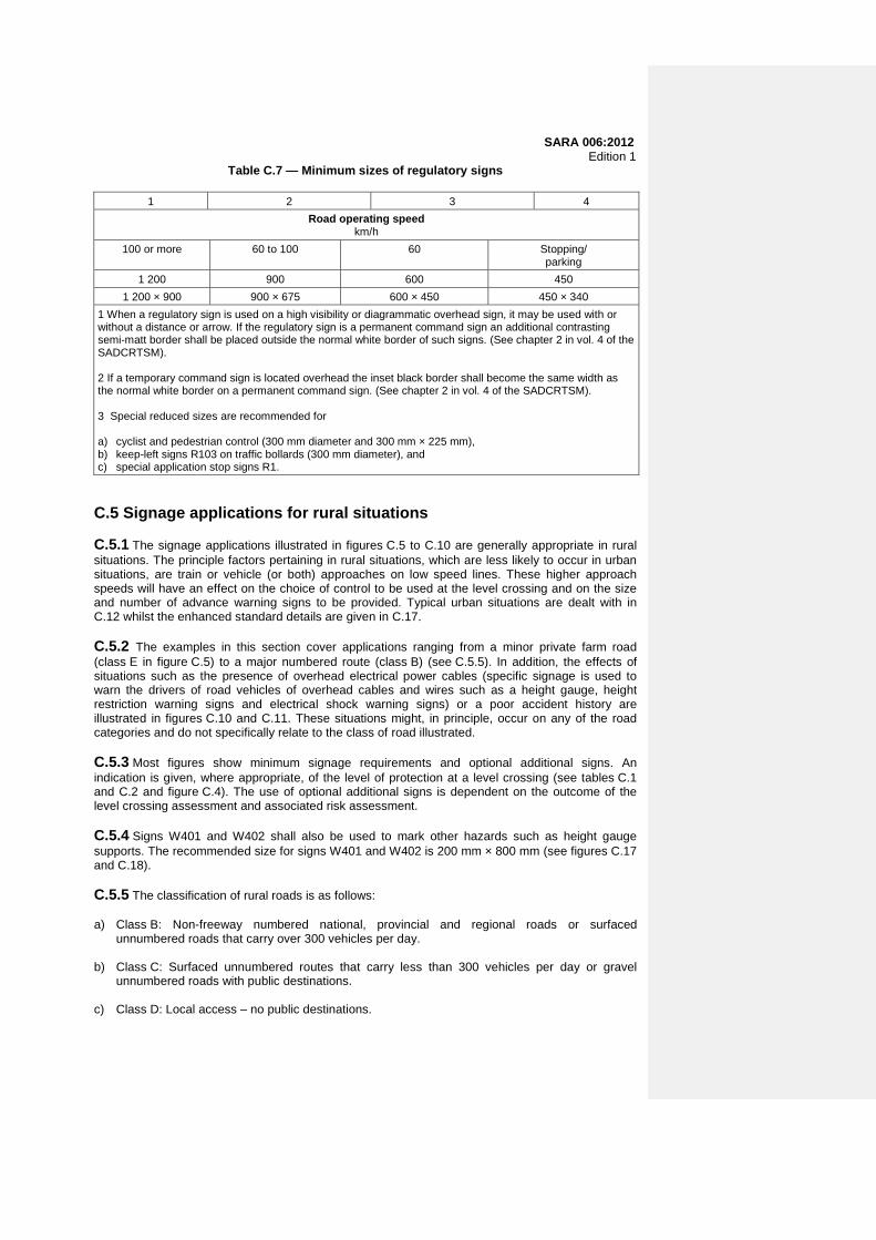
Table C.7 — Minimum sizes of regulatory signs
1 2 3 4
Road operating speed km/h
100 or more 60 to 100 60 Stopping/ parking
1 200 900 600 450
1 200 × 900 900 × 675 600 × 450 450 × 340
1 When a regulatory sign is used on a high visibility or diagrammatic overhead sign, it may be used with or without a distance or arrow. If the regulatory sign is a permanent command sign an additional contrasting semi-matt border shall be placed outside the normal white border of such signs. (See chapter 2 in vol. 4 of the SADCRTSM). 2 If a temporary command sign is located overhead the inset black border shall become the same width as the normal white border on a permanent command sign. (See chapter 2 in vol. 4 of the SADCRTSM). 3 Special reduced sizes are recommended for a) cyclist and pedestrian control (300 mm diameter and 300 mm × 225 mm), b) keep-left signs R103 on traffic bollards (300 mm diameter), and c) special application stop signs R1.
C.5 Signage applications for rural situations C.5.1 The signage applications illustrated in figures C.5 to C.10 are generally appropriate in rural situations. The principle factors pertaining in rural situations, which are less likely to occur in urban situations, are train or vehicle (or both) approaches on low speed lines. These higher approach speeds will have an effect on the choice of control to be used at the level crossing and on the size and number of advance warning signs to be provided. Typical urban situations are dealt with in C.12 whilst the enhanced standard details are given in C.17. C.5.2 The examples in this section cover applications ranging from a minor private farm road (class E in figure C.5) to a major numbered route (class B) (see C.5.5). In addition, the effects of situations such as the presence of overhead electrical power cables (specific signage is used to warn the drivers of road vehicles of overhead cables and wires such as a height gauge, height restriction warning signs and electrical shock warning signs) or a poor accident history are illustrated in figures C.10 and C.11. These situations might, in principle, occur on any of the road categories and do not specifically relate to the class of road illustrated. C.5.3 Most figures show minimum signage requirements and optional additional signs. An indication is given, where appropriate, of the level of protection at a level crossing (see tables C.1 and C.2 and figure C.4). The use of optional additional signs is dependent on the outcome of the level crossing assessment and associated risk assessment. C.5.4 Signs W401 and W402 shall also be used to mark other hazards such as height gauge supports. The recommended size for signs W401 and W402 is 200 mm × 800 mm (see figures C.17 and C.18). C.5.5 The classification of rural roads is as follows: a) Class B: Non-freeway numbered national, provincial and regional roads or surfaced
unnumbered roads that carry over 300 vehicles per day. b) Class C: Surfaced unnumbered routes that carry less than 300 vehicles per day or gravel
unnumbered roads with public destinations. c) Class D: Local access – no public destinations.

SARA 006:2012 Edition 1 d) Class E: Access road – private, farm road. C.6 Class E or farm road level crossings C.6.1 Figure C.5 shows the typical level of protection for a private Class E or farm road level crossing. Such a class is typically a gravel road. The owner/occupier of the property served by the road shall ensure that gates are locked when not in use and that they are only unlocked for individual road vehicle movements across the railway line. These gates are required on both sides of the railway line in terms of level of protection 2 (see figure C.4). C.6.2 If the private Class E or farm road crosses the railway line below overhead electrical power lines, electrical shock warning signs W361 and W314 shall be provided on each approach, in addition to the locked gates. C.7 Class C or D rural road crossing C.7.1 Figures C.6 and C.7 show a typical signage arrangement for a surfaced rural road and a rural gravel road, respectively, which can range from a minor public road to well-used roads carrying up to approximately 300 vehicles per day. Table C.2 and figure C.4 show control measures that involve a yield sign R2, stop sign R1, or traffic signals S1 as preferred options for this class of road. These options represent level of protection 2A to 6B. The use of yield sign R2 represents the lowest level of control for this class of road. The decision on the use of sign R1 or sign R2 is likely to rest on the available line of sight as indicated in tables C.3 and C.4. Reasons warranting the use of traffic signals S1 are given in C.4.4. Figure C.7 shows typical signage for gravel roads. For further detail see figures C.16 and C.17. C.7.2 The minimum signage required per approach, determined by the outcome of the assessment and the associated risk assessment, shall include where applicable a) an R2 – yield control sign, or b) an R1 – stop control sign, or c) an S1 – traffic signal, plus d) a W403 – level crossing hazard marker warning sign (single line), or e) a W404 -–level crossing hazard marker warning sign (two or more lines), plus f) an RTM1 – stop line road marking, g) an RM1 – no overtaking road marking, h) a WM1 – level crossing warning marking, and i) a W318 – level crossing advance warning sign. NOTE See figure C.4 and table C.2. C.7.3 Advance warning signs should be positioned in accordance with table C.5 if any of the conditions as described in 5.1 and 5.2 exists, and includes the following: a) W202 – W211 – road curve advance warning signs; b) W302 – stop control ahead advance warning signs;
31

SARA 006:2012 Edition 1 c) W314 – gate advance warning signs; d) W361 – electrical shock advance warning signs; e) W401 – danger plate hazard marker warning signs (left side); f) W402 – danger plate hazard marker warning signs (right side); g) IN11 – supplementary plate information signs; h) RM2 – no crossing lines road markings; i) a WM5 – yield road marking symbol; j) GM7 – word road markings ("stop"); and k) W301 – traffic signal ahead. C.8 Class B rural road crossing C.8.1 Crossings on this class of road are most likely to be on the regional numbered routes with higher traffic volumes. Dependent on the outcome of the assessment and the associated risk assessment, the use of a traffic signal S1 could be warranted on this class of road. (See figure C.8.) C.8.2 The minimum signage required per approach, determined by the outcome of the assessment and the associated risk assessment, shall include the following: a) an R2·–yield control sign; or b) an R1 – stop control sign; or c) an S1 – traffic light; plus d) a W403 – level crossing hazard marker warning sign (single line); or e) a W404 – level crossing hazard marker warning sign (two or more lines); plus f) an RTM1– stop line road marking; g) an RM1 – no overtaking road marking; h) a WM1 – level crossing warning marking; and i) a W318 – level crossing advance warning sign. C.8.3 Advance warning signs shall be considered for this level of protection based on the outcome of the assessment and the associated risk assessment. For details see figure C.8. C.8.4 Advance warning signs shall be positioned in accordance with the details given in table C.5 if any of the conditions as described in 5.1 and 5.2 exists, and include the following: a) W202 – W211 – road curve advance warning signs; b) W302 – stop control ahead advance warning signs; c) W314 – gate advance warning signs; d) W361 – electrical shock advance warning signs;

SARA 006:2012 Edition 1 e) W401 – danger plate hazard marker warning signs (left side); f) W402 – danger plate hazard marker warning signs (right side); g) IN11 – supplementary plate information signs; h) RM2 – no crossing lines road markings; i) a (0) WM5·– yield road marking symbol; j) GM2 – word road markings ("stop"); and k) a W301 – traffic signal ahead. NOTE See figure C.4 and table C.2. C.9 Overhead electrical power cables C.9.1 Figure C.9 provides warning signs for overhead electrical power cables (electrical shock advance warning sign W361) and the provision of height gauges for the overhead power cables for level crossings on electrified lines. Advance warning signs W318 and W361 shall be mounted on the same support. For further details see figures C.20 and C.21. C.9.2 Sign W361 is provided as a warning to road users including road vehicle drivers, their passengers and pedestrians, about the risk of raised objects that are in contact with the overhead electrical power cables. C.10 Height restricted overhead electrical power cables C.10.1 Full details on the provision of height gauges are given in C.18. C.10.2 When overhead electrical power cables are present the following signage shall be provided in relation to the power cable and the preceding height gauge: a) When the power cable is more than 5,1 m above the rail level, use sign WW7 on the height
gauge. b) When the power cable is between 4,7 m and 5,1 m above the rail level, use sign WW7 and two
W401 signs (pointing downwards) on the height gauge and sign W320 in advance of the crossing.
c) When the power cable is below 4,7 m above the rail level, use signs R204 and WW7 plus two
W401 signs on the height gauge and sign W320 in advance of the crossing. C.10.3 Figure C.10 illustrates the need to warn drivers of road vehicles well in advance of such a situation, so that they may choose an alternative route. Map-type direction sign GD9 may be designed to illustrate the specific detail of the alternative route when this is simple. If the alternative route is complex, supplementary guidance signs might be necessary. This signage treatment is recommended for any road carrying over 300 vehicles per day (Class B). Sign GD9 should carry a supplementary plate sign IN11.3 indicating the distance to the height restriction. C.10.4 For further details of the basic and optional signage for the actual rail crossing see C.5. C.10.5 Advance warning electrical shock sign W361 shall be specified in addition in all cases. It shall be noted that sign W362 is provided as a warning to road users, including drivers of motor vehicles, their passengers as well as pedestrians about the risk of raised objects that are in contact with the overhead electrical power cables. Sign WW7 gives the same message to service workers
33
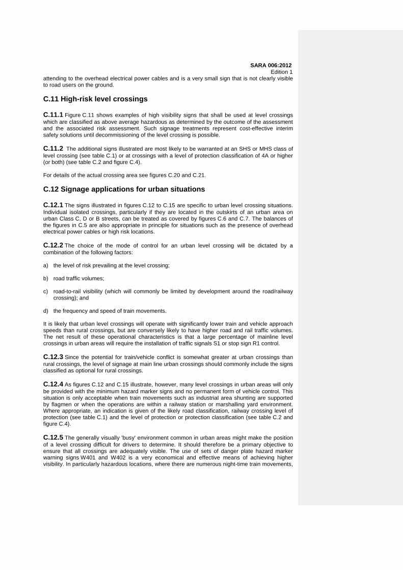
SARA 006:2012 Edition 1 attending to the overhead electrical power cables and is a very small sign that is not clearly visible to road users on the ground. C.11 High-risk level crossings C.11.1 Figure C.11 shows examples of high visibility signs that shall be used at level crossings which are classified as above average hazardous as determined by the outcome of the assessment and the associated risk assessment. Such signage treatments represent cost-effective interim safety solutions until decommissioning of the level crossing is possible. C.11.2 The additional signs illustrated are most likely to be warranted at an SHS or MHS class of level crossing (see table C.1) or at crossings with a level of protection classification of 4A or higher (or both) (see table C.2 and figure C.4). For details of the actual crossing area see figures C.20 and C.21. C.12 Signage applications for urban situations C.12.1 The signs illustrated in figures C.12 to C.15 are specific to urban level crossing situations. Individual isolated crossings, particularly if they are located in the outskirts of an urban area on urban Class C, D or B streets, can be treated as covered by figures C.6 and C.7. The balances of the figures in C.5 are also appropriate in principle for situations such as the presence of overhead electrical power cables or high risk locations. C.12.2 The choice of the mode of control for an urban level crossing will be dictated by a combination of the following factors: a) the level of risk prevailing at the level crossing; b) road traffic volumes; c) road-to-rail visibility (which will commonly be limited by development around the road/railway
crossing); and d) the frequency and speed of train movements. It is likely that urban level crossings will operate with significantly lower train and vehicle approach speeds than rural crossings, but are conversely likely to have higher road and rail traffic volumes. The net result of these operational characteristics is that a large percentage of mainline level crossings in urban areas will require the installation of traffic signals S1 or stop sign R1 control. C.12.3 Since the potential for train/vehicle conflict is somewhat greater at urban crossings than rural crossings, the level of signage at main line urban crossings should commonly include the signs classified as optional for rural crossings. C.12.4 As figures C.12 and C.15 illustrate, however, many level crossings in urban areas will only be provided with the minimum hazard marker signs and no permanent form of vehicle control. This situation is only acceptable when train movements such as industrial area shunting are supported by flagmen or when the operations are within a railway station or marshalling yard environment. Where appropriate, an indication is given of the likely road classification, railway crossing level of protection (see table C.1) and the level of protection or protection classification (see table C.2 and figure C.4). C.12.5 The generally visually 'busy' environment common in urban areas might make the position of a level crossing difficult for drivers to determine. It should therefore be a primary objective to ensure that all crossings are adequately visible. The use of sets of danger plate hazard marker warning signs W401 and W402 is a very economical and effective means of achieving higher visibility. In particularly hazardous locations, where there are numerous night-time train movements,

SARA 006:2012 Edition 1 it shall ultimately be necessary for the safe operation of a crossing to install street lighting. Lighting located at the crossing only shall not be provided on an isolated basis, without properly designed approach lighting. C.12.6 When preparing a specification for the signage of a new or upgraded level crossing, or when reviewing the signage of an existing level crossing, an assessment of the level crossing shall be conducted. C.12.7 Urban road classification shall be as follows: a) Class B: Non-freeway numbered metropolitan routes; b) Class C: Unnumbered urban streets of intermediate importance; and c) Class D: Local residential streets. C.13 Industrial siding level crossings C.13.1 All industrial sidings with cross roads shall be appropriately identified on each approach by a level crossing hazard marker warning sign W403 or W404. These signs may be provided with a rectangular backing board for greater resistance to damage. The backing board may be provided with a semi-matt grey finish. If it is evident that drivers misjudge the number of rail lines to be crossed, supplementary plate information sign IN11.4, with a message such as "4 lines" should be fixed below sign W404. Figures C.12 and C.15 illustrate these basic signage principles. This type of crossing will normally be classified as SSH or MSH (see table C.1) although it is also possible that such a crossing could include a mainline with shunting lines. The level of protection commonly appropriate at industrial crossings is level of protection 1 (see table C.2 and figure C.4). C.13.2 Traffic control should normally be achieved at this type of level crossing using flag signals SS2. This means that at all other times that a flag is not displayed vehicle drivers may cross the lines without stopping. All individual train shunting operations should be accompanied by a flagman capable of acting for both road approaches. If this is not practical then two flagmen should be used, one for each approach. All flags shall be clean and of a bright red or red-orange colour. A flag may be replaced by a portable RED light signal if night-time shunting is required and vehicular traffic volumes are low. C.13.3 If manual control of such crossings is not safely manageable, at night-time for instance, then traffic control shall be automated using stop sign R1 or traffic signals S1 in addition to signs W403 or W404 + IN11.4. C.13.4 The only additional signage that might be required is the use of danger plate hazard marker warning signs W401 and W402 to better define the width and position of the crossings, or standard advance warning signs appropriate to a particular roadway approach condition such as a sharp bend (see figure C.17). C.13.5 If individual sidings or shunting lines are provided with overhead electrical power cables height gauges and advance warning signs, W356 should be installed. C.14 Class B urban street crossings C.14.1 Level crossings that involve Class B numbered urban routes are not likely to occur frequently. However, in large towns or cities, crossings on such routes will almost certainly be subject to large volumes of vehicular traffic and in smaller towns the vehicular traffic will probably include significant percentages of long-distance travellers who will not be familiar with local conditions. Visibility of such crossings shall therefore be optimized and operational safety maximized by use of the most effective control facilities practicable.
35

SARA 006:2012 Edition 1 Urban Class B routes may commonly be multi-lane roadways. This will add to the complexity of crossing control measures. Figure C.13 shows a typical four lane urban road/rail crossing. C.14.2 Traffic control at a Class B urban street level crossing shall comply with the principles given in C.7 for similar rural crossings, subject to adjustment in the positions of signs to take into account different orders of vehicle approach speeds. The use of stop sign R1 or traffic signals S1 control will almost always be required for a Class B street crossing, particularly if the street is a multi-lane street. This represents a level of protection 4C to level of protection 6B (see table C.2 and figure C.4). Only if full visibility of approaching trains is available in accordance with the requirements of tables C.3 and C.4 and other factors influencing driver performance are favourable (see chapter 1 in vol. 1 of the SADCRTSM), a lower level of control shall be considered. C.14.3 A high volume urban level crossing shall warrant the installation of boom protection. Boom protection increases the visual impact of the crossing to the first drivers to approach it and also controls the release of vehicles when the lines are once more clear for crossing (level of protection 6B). In addition to traffic signals S1 and booms it might also be beneficial to install alarm bells, although the environmental impact of such a measure will have to be carefully assessed. The use of high visibility signs might also be warranted as indicated in figure C.13. A multi-lane approach will reduce the effectiveness of standard sized advance warning signs. The signs displayed should take into account the prevailing conditions, such as a) overhead electrical power cables (see figures C.18 and C.20), b) boom protection ("gates" – see figure C.18), c) high speed trains, and d) low level power cables (see figure C.10). Additional road markings are also recommended.
Multi-lane approaches should be treated as for a standard multi-lane signalized junction. Level crossing warning marking WM1 may be used several times, in each lane, to improve awareness of the approaching crossing.
C.15 Urban crossing of parallel railway lines C.15.1 Figure C.14 shows an urban situation that is particularly difficult to sign with clarity. The railway lines are commonly very close to the parallel road so that very little warning can be given on one of the crossing road approaches if the presence of the lines is not obvious from the parallel road. Special attention shall therefore be given to the need for optional signing. C.15.2 The mode of traffic control shall comply with the normal requirements for the use of yield sign R2, stop sign R1, stop sign R1 or traffic signals S1. A crossing of this nature could occur on almost any Class B, C or D urban street although it is less likely on a Class B street. The classification of a level crossing could range from an SSH to an MLS (see table C.1) and the level of protection from a level of protection 3A, which is illustrated, to a level of protection 6B (see table C.2 and figure C.4). C.15.3 When parallel road and rail lines are close together it might be advisable to provide a specially designed diagrammatic sign to inform drivers of the junction/level crossing configuration. This sign might be warranted for a junction with a closely spaced railway line when otherwise the junction itself would not normally warrant an advance warning sign. If the distance between the intersection and the level crossing is more that 100 m, use advance warnings signs on the approach road to the level crossing rather than the GS901/GS902 signs. A distance less than 50 m between the stop line at the intersection and the railway line shall be avoided.
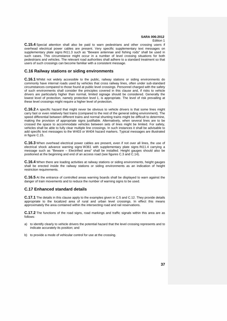
SARA 006:2012 Edition 1 C.15.4 Special attention shall also be paid to warn pedestrians and other crossing users if overhead electrical power cables are present. Very specific supplementary text messages on supplementary plate signs IN11.3 such as "Beware antennae and fishing rods" shall be used in such cases. This circumstance might occur in a number of level crossing situations for both pedestrians and vehicles. The relevant road authorities shall adhere to a standard treatment so that users of such crossings can become familiar with a consistent message. C.16 Railway stations or siding environments C.16.1 Whilst not widely accessible to the public, railway stations or siding environments do commonly have internal roads used by vehicles that cross railway lines, often under sub-standard circumstances compared to those found at public level crossings. Personnel charged with the safety of such environments shall consider the principles covered in this clause and, if risks to vehicle drivers are particularly higher than normal, limited signage should be considered. Generally the lowest level of protection, namely protection level 1, is appropriate. The level of risk prevailing at these level crossings might require a higher level of protection. C.16.2 A specific hazard that might never be obvious to vehicle drivers is that some lines might carry fast or even relatively fast trains (compared to the rest of the general siding environment). The speed differential between different trains and normal shunting trains might be difficult to determine, making the provision of appropriate signs justifiable. Alternatively, when several lines are to be crossed the space to accommodate vehicles between sets of lines might be limited. For safety, vehicles shall be able to fully clear multiple line crossings. In such instances it shall be advisable to add specific text messages to the W403 or W404 hazard markers. Typical messages are illustrated in figure C.15. C.16.3 When overhead electrical power cables are present, even if not over all lines, the use of electrical shock advance warning signs W361 with supplementary plate signs IN11.4 carrying a message such as "Beware – Electrified area" shall be installed. Height gauges should also be positioned at the beginning and end of an access road (see figures C.3 and C.14). C.16.4 When there are loading activities at railway stations or siding environments, height gauges shall be erected inside the railway stations or siding environments as an indication of height restriction requirements. C.16.5 At the entrance of controlled areas warning boards shall be displayed to warn against the danger of train movements and to reduce the number of warning signs to be used. C.17 Enhanced standard details C.17.1 The details in this clause apply to the examples given in C.5 and C.12. They provide details appropriate to the localized area of rural and urban level crossings. In effect this means approximately the area contained within the intersecting road and rail reservations. C.17.2 The functions of the road signs, road markings and traffic signals within this area are as follows: a) to identify clearly to vehicle drivers the potential hazard that the level crossing represents and to
indicate accurately its position; and b) to provide a mode of vehicular control for use at the crossing.
37

SARA 006:2012 Edition 1 As indicated in the earlier figures all level crossings shall have sufficient signs to fulfil the first function. Signs for the second function may be omitted for low speed, low frequency crossings that are controlled by flagmen but that shall be provided in accordance with the crossing and protection classifications given in tables C.1 and C.2. C.17.3 Figures C.16 to C.20 show typical situations. Many variable factors might be involved that will call for detailed changes, but the basic principles illustrated shall be noted and adhered to. The classes of road, crossing, and protection illustrated shall be as follows: a) Figure C.16: Class C, D or E gravel road, Class SLS crossing, and level of protection 2, 2A
and 3. b) Figure C.17: Class B or C road, Class MLS crossing and level of protection 4A to 4D or 5. c) Figures C.18 to C.20: Class B road, Class MHS crossing, and level of protection 5, 6A or 6B. C.17.4 The following road markings shall be introduced at all surfaced road approaches to level crossings: a) The dividing line between opposing traffic streams shall be marked as a no-overtaking line
marking RM1 or a no-crossing line marking RM2 for a minimum of 96 m in rural environments and 48 m in urban areas. The lines shall start at the transverse stop line or yield line and shall not continue over the level crossing. Longer lengths of line may be used.
b) Stop line marking RTM1 or yield line marking RTM2 shall be marked a minimum of 4,5 m from
the outer rail. Lines RTM1 or RTM2 may be placed further from the outer rail but this will affect the line of sight to approaching trains.
c) In the case of roads provided with shoulders edge line marking RM4.1 shall be continuous over
the crossing to provide visual continuity of the road. d) "Stop" word marking GM7 shall be provided between 1 m and 5 m before the stop line marking.
The marking shall be repeated in the form "Stop ahead" for emphasis, approximately at the appropriate slopping line of sight for the approach speed from the stop line.
e) Level crossing warning marking WM1 shall be provided according to the distances given in
table C.6 (distance C1). The marking shall be repeated for emphasis near the start of the RM1 or RM2 marking to further inhibit overtaking on the approach to the crossing.
f) The use of the box junction marking RM10 shall be introduced at all level crossings where there
is a possibility of vehicles queuing over the railway level crossing. C.17.5 Figure C.19 shows two typical situations in which signs shall be required to control or warn pedestrians. Figure C.19 also shows a typical pedestrian footpath level crossing with signs provided specifically for the attention of pedestrians. Signage at stations is used in the example of a pedestrian crossing in a station environment between platforms. C.17.6 Figure C.21 gives details of the construction and signage of a height gauge. C.18 Height gauges and sign display details C.18.1 Figure C.21 gives various criteria for the provision of a height gauge and the correct placing of retro-reflective signs. C.18.2 The relevant national legislation (see foreword) requires the provision of a height gauge in advance of any overhead electrical power cable over a level crossing. The principle purpose of this gauge is to make drivers aware that high aerial or similar devices might cause a flash-over from the power cable. The gauge should be positioned between stop line RTM1 and the railway line(s).
SARA 006:2012 Edition 1 C.18.3 The height gauge wires shall be positioned 300 mm below the level of the lowest point of the overhead electrical power cable for a 3 kV DC or a 25 kV AC power cable, and 500 mm below the lowest point of the overhead electrical power cable for a 50 kV AC power cable. C.18.4 When the power cable has a minimum clearance height in excess of 5,1 m only sign WW7 needs to be provided on the height gauge over each lane. C.18.5 When the clearance is between 5,1 m and 4,7 m two hazard marker signs W401 should be provided approximately 2 m either side of sign WW7. The height gauge should be preceded by advance warning sign W320. C.18.6 If the power cable is lower than 4,7 m an appropriate prohibition height limit sign R204 plus two W415 signs shall be displayed on the height gauge and the installation should be preceded by advance warning sign W320. In this case, wherever possible, an alternative route should be signed to divert high vehicles around such a crossing (see figure C.21). C.18.7 All measurements of H shall be made to the highest part of the road surface. C.18.8 In order to avoid specular reflection from fully retro-reflective regulatory and warning signs all such signs shall be rotated 3° away from an imaginary line taken at 90° from the road dividing line. C.18.9 It should be noted that sign W361 is provided as a warning to road users including drivers, their passengers, and pedestrians, about the risk of raised objects that are in contact with the overhead electrical power cables. Sign WW7 (see C.10 and figure C.21) gives the same message to service workers attending to the overhead electrical power cables and is a very small sign not clearly visible to road users on the ground.
39
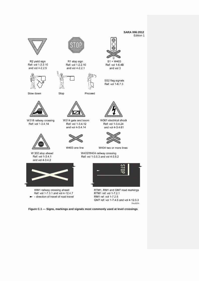
SARA 006:2012 Edition 1
Figure C.1 — Signs, markings and signals most commonly used at level crossings
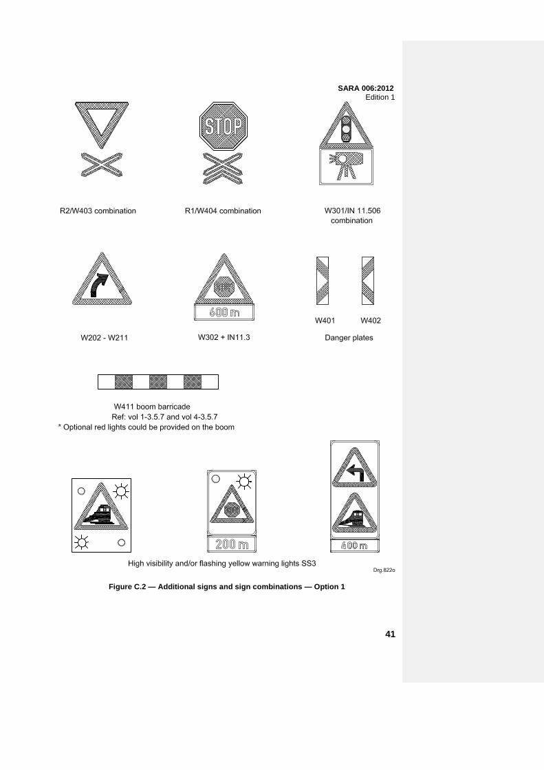
SARA 006:2012 Edition 1
Figure C.2 — Additional signs and sign combinations — Option 1
41
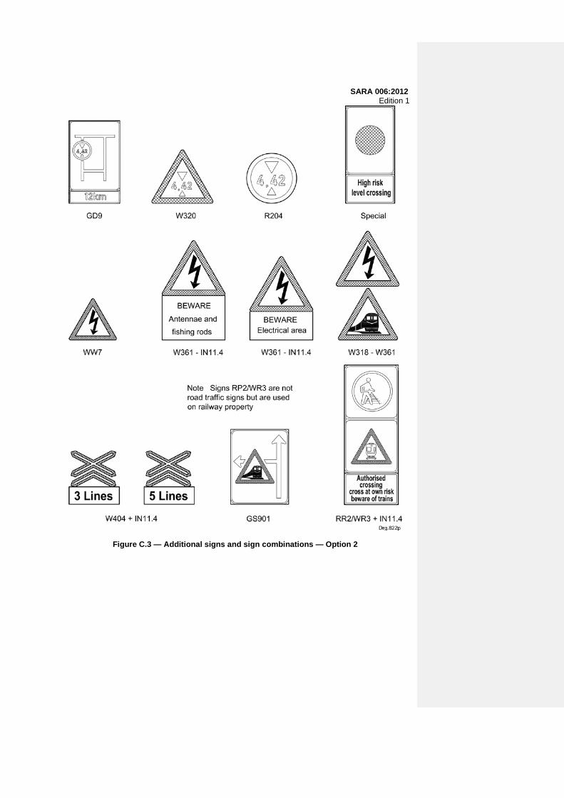
SARA 006:2012 Edition 1
Figure C.3 — Additional signs and sign combinations — Option 2
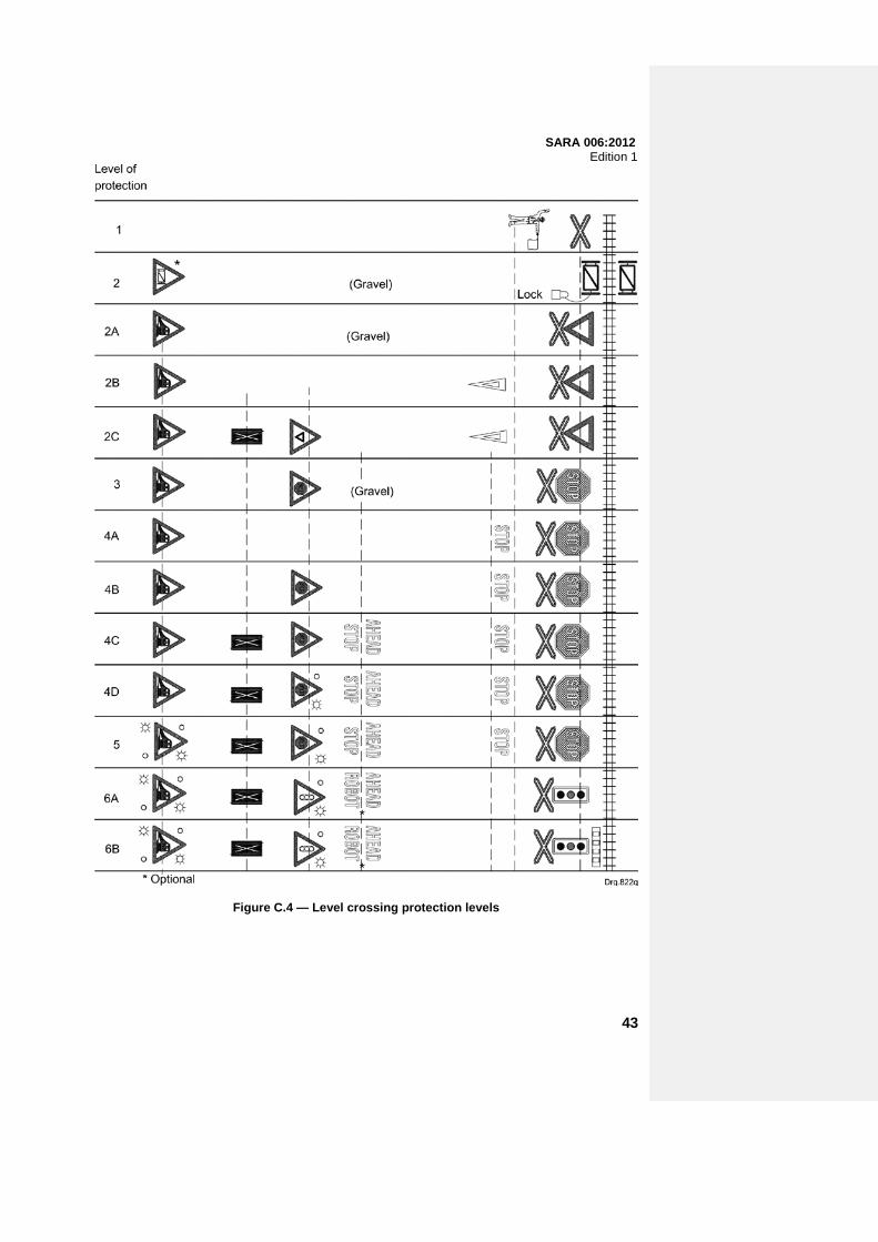
SARA 006:2012 Edition 1
Figure C.4 — Level crossing protection levels
43
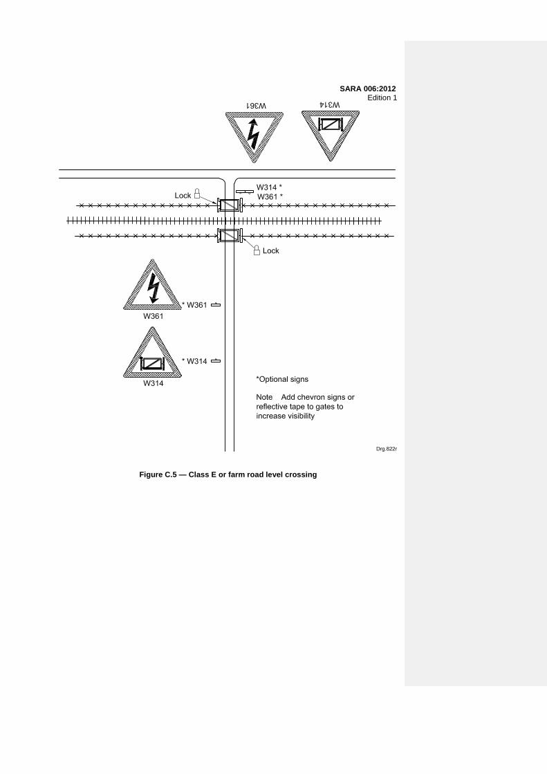
SARA 006:2012 Edition 1
Figure C.5 — Class E or farm road level crossing

SARA 006:2012 Edition 1
Figure C.6 — Class C or D rural surfaced road level crossing
45

SARA 006:2012 Edition 1
Figure C.7 — Class C or D rural road level crossing on gravel road

SARA 006:2012 Edition 1
Figure C.8 — Class B rural road level crossing
47

SARA 006:2012 Edition 1
Figure C.9 — Overhead electrical power lines

SARA 006:2012 Edition 1
Figure C.10 — Low level overhead electrical power lines
49

SARA 006:2012 Edition 1
Figure C.11 — High risk level crossings

SARA 006:2012 Edition 1
Figure C.12 — Industrial siding level crossing
51

SARA 006:2012 Edition 1
Figure C.13 — Class B urban street level crossing — Multi-lane street
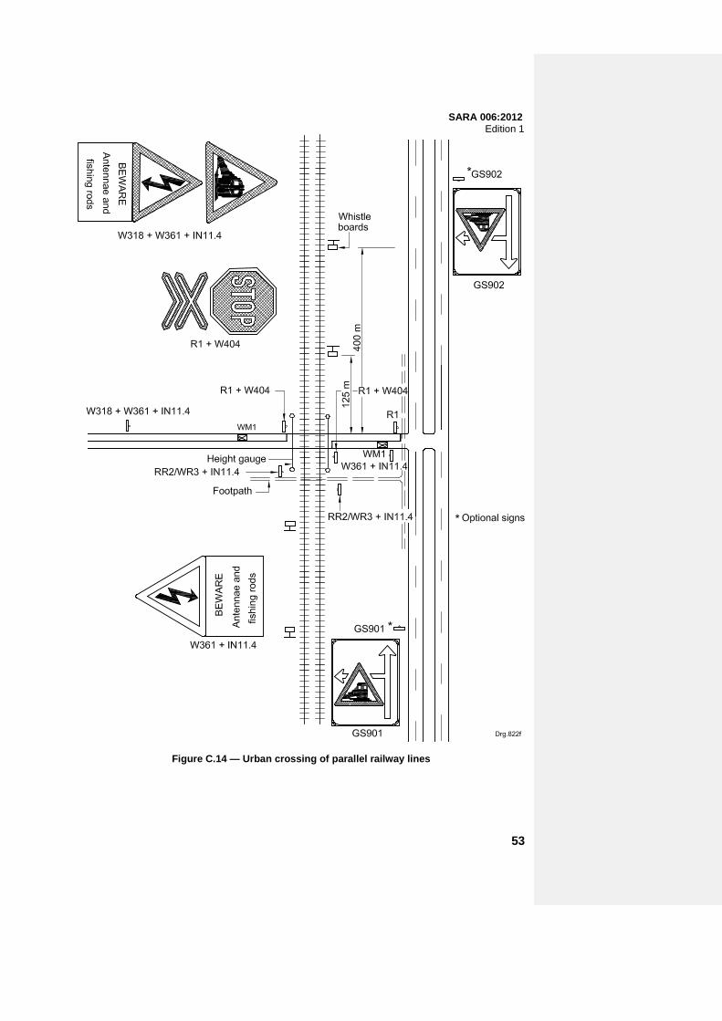
SARA 006:2012 Edition 1
Figure C.14 — Urban crossing of parallel railway lines
53

SARA 006:2012 Edition 1
Figure C.15 — Railway siding environments
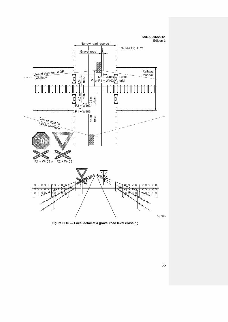
SARA 006:2012 Edition 1
Figure C.16 — Local detail at a gravel road level crossing
55

SARA 006:2012 Edition 1
Figure C.17 — Local detail at a rural road surfaced level crossing

SARA 006:2012 Edition 1
Figure C.18 — Local detail at a boom protected level crossing
57

SARA 006:2012 Edition 1
Figure C.19 — Pedestrian level crossing

SARA 006:2012 Edition 1
Figure C.20 — Local detail at traffic signal and boom protected level crossing
59

SARA 006:2012 Edition 1
Figure C.21 — Height gauge and display details
SARA 006:2012 Edition 1
Annex D (informative)
Model for the division of costs for the elimination of level crossings
D.1 General Once a physical assessment and the resultant risk assessment demonstrate that the residual risk, having applied the maximum protection, remains unacceptably high, the only alternative is either to permanently close the level crossing or to eliminate the level crossing by means of a road-over-rail or a rail-over-road structure. D.2 Background D.2.1 Experience has shown that in most cases where level crossing have been eliminated in the past, both the road authority and the railway operator wanted to make provision for future growth and capacity improvements. D.2.2 The following five models, with alternative allocation of construction and maintenance costs, provide guidance with regard to the relative responsibilities of the road authority and the railway operator (network operator) or network owner for capital and maintenance costs: a) Model 1: Elimination of a level crossing with a road-over-rail bridge across existing railway lines
and to the width of the existing road. (See figure D.1.) b) Model 2: Elimination of a level crossing with a road-over-rail bridge across existing railway lines
and making provision for proposed road widening. (See figure D.2.) c) Model 3: Elimination of a level crossing with a road-over-rail bridge across existing railway lines
making provision for future railway lines and to the width of the existing road. (See figure D.3.) d) Model 4: Elimination of a level crossing with a road-over-rail bridge across existing railway lines
making provision for future railway lines and proposed road widening. (See figure D.4.) e) Model 5: Elimination of a level crossing with a road-over-rail bridge across existing or future
railway lines as well as an existing or future public road, and making provision for proposed road widening. (See figure D.5.)
61
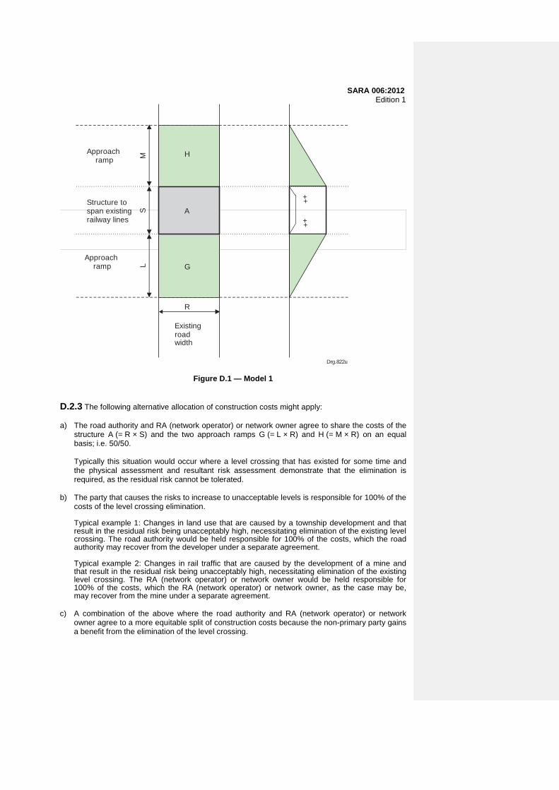
SARA 006:2012 Edition 1
Existingroadwidth
R
LM
SApproach ramp
Structure tospan existingrailway lines
Approach ramp
++
++
Drg.822u
H
A
G
Figure D.1 — Model 1 D.2.3 The following alternative allocation of construction costs might apply: a) The road authority and RA (network operator) or network owner agree to share the costs of the
structure A (= R × S) and the two approach ramps G (= L × R) and H (= M × R) on an equal basis; i.e. 50/50.
Typically this situation would occur where a level crossing that has existed for some time and the physical assessment and resultant risk assessment demonstrate that the elimination is required, as the residual risk cannot be tolerated.
b) The party that causes the risks to increase to unacceptable levels is responsible for 100% of the
costs of the level crossing elimination.
Typical example 1: Changes in land use that are caused by a township development and that result in the residual risk being unacceptably high, necessitating elimination of the existing level crossing. The road authority would be held responsible for 100% of the costs, which the road authority may recover from the developer under a separate agreement.
Typical example 2: Changes in rail traffic that are caused by the development of a mine and that result in the residual risk being unacceptably high, necessitating elimination of the existing level crossing. The RA (network operator) or network owner would be held responsible for 100% of the costs, which the RA (network operator) or network owner, as the case may be, may recover from the mine under a separate agreement.
c) A combination of the above where the road authority and RA (network operator) or network
owner agree to a more equitable split of construction costs because the non-primary party gains a benefit from the elimination of the level crossing.

SARA 006:2012 Edition 1 D.3 Maintenance and decommissioning D.3.1 Maintenance of the road surface and associated drainage will be 100% for the account of the road authority. Apart from parapet walls, the maintenance of the structure will be shared in direct proportion to the actual final cost of the structure as calculated above. The responsibility for 100% of the repair and maintenance costs of parapet walls will be as follows: a) in the case of a road-over-rail structure, the road authority; and b) in the case of a rail-over-road structure, the railway operator (network operator) or network
owner. The cost of decommissioning (demolition) shall be shared between the road authority and the RA (network operator) or network owner in the same proportion as the cost of construction.
Existingroadwidth
R
LM
S
Approach ramp
Structure width to spanexistingrailway lines
Approach ramp
++
++
Drg.822v
H
A
G
J
C
I
Proposedroadwidening
W
Figure D.2 — Model 2 D.3.2 The following division of costs might apply: a) Alternative 1: The road authority and RA (network operator) or network owner agree to share
the costs of the structure A (= R × S) and the two approach ramps G (= L × R) and H (= M × R) on an equal basis; i.e. 50/50.
Typically this situation would occur where a level crossing that has existed for some time and
the physical assessment and resultant risk assessment demonstrate that the elimination is required, as the residual risk cannot be tolerated.
63
SARA 006:2012 Edition 1 The road authority is entirely responsible for the costs of the widened structure C (= W × S) and
the associated widened approach ramps I (= L × W) and J (= M × W). b) Alternative 2: The road authority is responsible for 100% of the costs of the level crossing
elimination as a result of changes in road traffic causing the risks to increase to unacceptable levels, including the costs associated with road widening, which the road authority may recover in whole or in part from a third party under a separate agreement.
A typical example: Changes in land use that are caused by a township development and that
result in the residual risk being unacceptably high necessitating elimination of the existing level crossing.
c) Alternative 3: The RA (network operator) or network owner is responsible for 100% of the costs
of elimination to the width of the existing road, which the RA (network operator) or network owner, as the case may be, may recover in whole or in part from a third party under a separate agreement. The road authority would be responsible for 100% of the costs of the structure and the associated approach ramps to accommodate the widened road.
A typical example: Changes in rail traffic that are caused by the development of a mine and that
result in the residual risk being unacceptably high necessitating elimination of the existing level crossing.
d) Alternative 4: A combination of the above where the road authority and RA (network operator)
or network owner agree to a more equitable split of construction costs because the non-primary party gains a benefit from the elimination of the level crossing.
D.3.3 Maintenance of the road surface and associated drainage will be 100% for the account of the road authority. Apart from parapet walls, the maintenance of the structure will be shared in direct proportion to the actual final cost of the structure as calculated above. The responsibility for 100% of the repair and maintenance costs of parapet walls will be as follows: a) in the case of a road-over-rail structure, the road authority; and b) in the case of a rail-over-road structure, the RA (network operator) or network owner. The cost of decommissioning (demolition) shall be shared between the road authority and the RA (network operator) or network owner in the same proportion as the cost of construction.

SARA 006:2012 Edition 1
Existingroadwidth
R
LM
S
Approach ramp
Structure to span futurerailway lines
++
++
Drg.822w
H
B
G
A ++
Approach ramp
Structure to span existingrailway lines
T
Figure D.3 — Model 3 D.4 Elimination of a level crossing with a road-over-rail bridge across existing railway lines making provision for future railway lines and the width of the existing road D.4.1 The following division of costs might apply: a) Alternative 1: 1) The road authority and RA (network operator) or network owner agree to share the costs of
the structure A (= R × S) and the two approach ramps G (= L × R) and H (= M × R) on an equal basis; i.e. 50/50.
Typically this situation would occur where a level crossing that has existed for some time and the physical assessment and resultant risk assessment demonstrate that the elimination is required, as the residual risk cannot be tolerated.
2) The RA (network operator) or network owner is entirely responsible for the costs of lengthening the structure B (= T × R) to accommodate additional railway lines and maintenance road (where applicable).
b) Alternative 2.
65

SARA 006:2012 Edition 1 The road authority is responsible for 100% of the costs of the level crossing elimination to span
existing railway lines as a result of changes in road traffic causing the risks to increase to unacceptable levels, and the RA (network operator) or network owner, is responsible for 100% of the costs of lengthening the structure T (= B × R) to accommodate future railway lines and maintenance road (where applicable). The road authority may recover its portion of the costs in whole or in part from a third party under a separate agreement.
A typical example: Changes in land use that are caused by a township development and that
result in the residual risk being unacceptably high necessitating elimination of the existing level crossing.
c) Alternative 3.
The RA (network operator) or network owner is responsible for 100% of the costs of elimination to the width of the existing road, which the railway operator (network operator) or network owner, as the case may be, may recover in whole or in part from a third party under a separate agreement.
A typical example: Changes in rail traffic that are caused by the development of a mine and that result in the residual risk being unacceptably high necessitating elimination of the existing level crossing.
d) Alternative 4
A combination of the above where the road authority and RA (network operator) or network owner agree to a more equitable split of construction costs because the non-primary party gains a benefit from the elimination of the level crossing.
D.4.2 Maintenance of the road surface and associated drainage will be 100% for the account of the road authority. Apart from parapet walls, the maintenance of the structure will be shared in direct proportion to the actual final cost of the structure as calculated above. The responsibility for 100% of the repair and maintenance costs of parapet walls will be as follows: a) in the case of a road-over-rail structure, the road authority; and b) in the case of a rail-over-road structure, the RA (network operator) or network owner. The cost of decommissioning (demolition) shall be shared between the road authority and the RA (network operator) or network owner in the same proportion as the cost of construction.
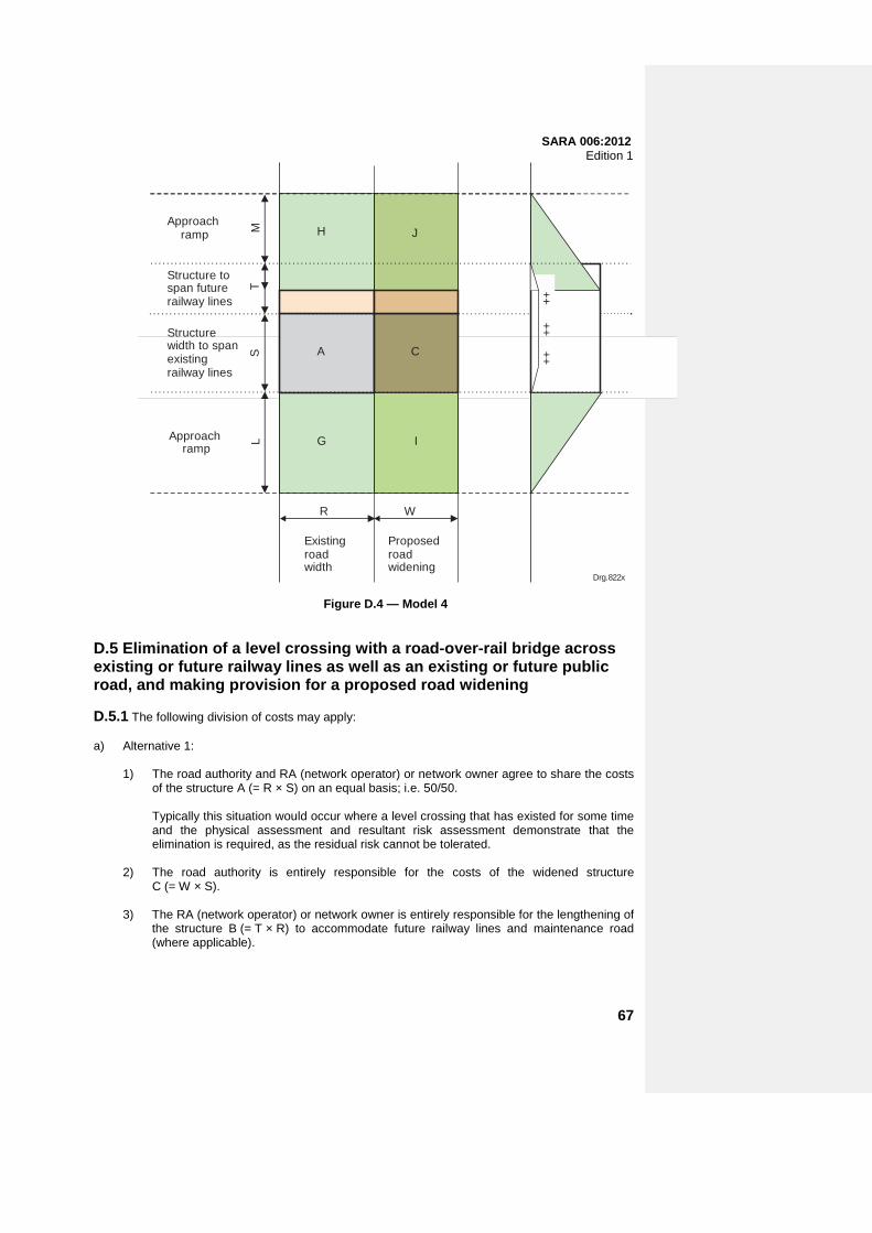
SARA 006:2012 Edition 1
Existingroadwidth
R
LM
S
Approach ramp
Structure width to spanexistingrailway lines
Approach ramp
++
++
Drg.822x
H
A
G
J
C
I
Proposedroadwidening
W
++
Structure to span futurerailway lines
T
Figure D.4 — Model 4 D.5 Elimination of a level crossing with a road-over-rail bridge across existing or future railway lines as well as an existing or future public road, and making provision for a proposed road widening D.5.1 The following division of costs may apply: a) Alternative 1: 1) The road authority and RA (network operator) or network owner agree to share the costs
of the structure A (= R × S) on an equal basis; i.e. 50/50.
Typically this situation would occur where a level crossing that has existed for some time and the physical assessment and resultant risk assessment demonstrate that the elimination is required, as the residual risk cannot be tolerated.
2) The road authority is entirely responsible for the costs of the widened structure
C (= W × S). 3) The RA (network operator) or network owner is entirely responsible for the lengthening of
the structure B (= T × R) to accommodate future railway lines and maintenance road (where applicable).
67
SARA 006:2012 Edition 1
4) The costs of the structure D as the result of widening and lengthening the structure to accommodate respectively the proposed road widening and future railway lines are shared as follows:
— The RA (network operator) or network owner is responsible for D × B/ (B + C); — The road authority is responsible for D × C/ (B + C)
5) The costs of the approach ramps, including earthwork, drainage and road surface
structure are shared as follows:
— The RA (network operator) or network owner is responsible for (½G / (G + I) × (cost of ramp (G + I)) + (½H/ (H + J) × (cost of ramp (H + J)) ;
— The road authority is responsible for ((½G + I)/ (G + I) × (cost of ramp
(G + I) + (½H + J)/ (H + J) × (cost of ramp (H + J)) b) Other alternatives: The same alternatives as described in models 2 and 3 may be considered
for the allocation of the construction costs. D.5.2 Maintenance of the road surface and associated drainage will be 100% for the account of the road authority. Apart from parapet walls, the maintenance of the structure will be shared in direct proportion to the actual final cost of the structure as calculated above. The responsibility for 100% of the repair and maintenance costs of parapet walls will be as follows: a) in the case of a road-over-rail structure, the road authority; and b) in the case of a rail-over-road structure, the RA (network operator) or network owner. The costs of decommissioning (demolition) shall be shared between the road authority and the RA (network operator) or network owner in the same proportion as the costs of construction. D.5.3 The same alternatives described in model 4 are applicable, with the addition that the construction and maintenance costs of the structure over an existing or future public road are the responsibility of the road authority.
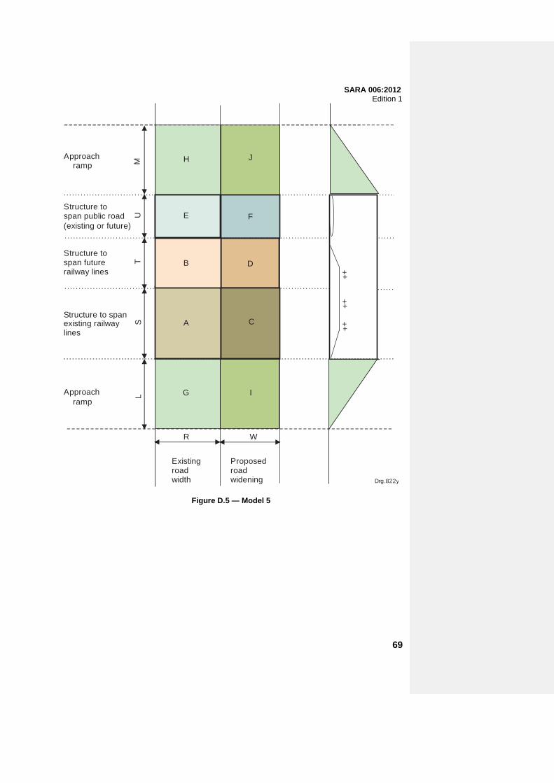
SARA 006:2012 Edition 1
R
LM
T
Approach ramp
Approach ramp
++
++
Drg.822y
H J
F
W
++
Structure to span futurerailway lines
U
A C
Existingroadwidth
Proposedroadwidening
G I
B D
C
E
B
Structure to span public road(existing or future)
S
R W
Structure to spanexisting railway lines
Figure D.5 — Model 5
69