save vtr 250/b - rekuperatoriucentras.lt · this installation manual concerns air handling unit...
TRANSCRIPT

Document in original language | 211473 · A001
SAVE VTR 250/BInstallation and Service GB

211473 | A001
© Copyright Systemair UABAll rights reservedE&OESystemair UAB reserves the rights to alter their products without notice.This also applies to products already ordered, as long as it does not affect the previously agreed specifications.Systemair is not liable or bound by warranty if these instructions are not adhered to during installation or service.

211473 | A001
Contents
1 Declaration of Conformity .. . . . . . . . . . . . . . . . . . . . . . . . . . . . . . . .12 Disposal and recycling .. . . . . . . . . . . . . . . . . . . . . . . . . . . . . . . . . . . . .23 Warnings. . . . . . . . . . . . . . . . . . . . . . . . . . . . . . . . . . . . . . . . . . . . . . . . . . . . . . .24 About this document.. . . . . . . . . . . . . . . . . . . . . . . . . . . . . . . . . . . . . . .25 Product information .. . . . . . . . . . . . . . . . . . . . . . . . . . . . . . . . . . . . . . . .2
5.1 General . . . . . . . . . . . . . . . . . . . . . . . . . . . . . . . . . . . . . . . . . . . . . . . .25.2 Installation recommendation regarding
condensation .. . . . . . . . . . . . . . . . . . . . . . . . . . . . . . . . . . . . . . .35.2.1 Condensation inside of the
unit . . . . . . . . . . . . . . . . . . . . . . . . . . . . . . . . . . . . . . . . .35.2.2 Condensation outside of the
unit . . . . . . . . . . . . . . . . . . . . . . . . . . . . . . . . . . . . . . . . .35.3 Transport and storage .. . . . . . . . . . . . . . . . . . . . . . . . . . . .35.4 Technical Data . . . . . . . . . . . . . . . . . . . . . . . . . . . . . . . . . . . . . . .4
5.4.1 Dimensions and Weight, Lmodel. . . . . . . . . . . . . . . . . . . . . . . . . . . . . . . . . . . . . .4
5.4.2 Dimensions and Weight, Rmodel. . . . . . . . . . . . . . . . . . . . . . . . . . . . . . . . . . . . . .5
5.4.3 Connections Left and Rightmodels .. . . . . . . . . . . . . . . . . . . . . . . . . . . . . . . . . . .6
5.4.4 Power consumption and fusesize . . . . . . . . . . . . . . . . . . . . . . . . . . . . . . . . . . . . . . . . .6
6 Installation.. . . . . . . . . . . . . . . . . . . . . . . . . . . . . . . . . . . . . . . . . . . . . . . . . . . .66.1 Unpacking .. . . . . . . . . . . . . . . . . . . . . . . . . . . . . . . . . . . . . . . . . . .76.2 Where/how to install . . . . . . . . . . . . . . . . . . . . . . . . . . . . . .76.3 Installation procedure.. . . . . . . . . . . . . . . . . . . . . . . . . . . . .76.4 Condensation drainage .. . . . . . . . . . . . . . . . . . . . . . . . . . .76.5 Open the front hatch.. . . . . . . . . . . . . . . . . . . . . . . . . . . . . .8
7 SAVECair control . . . . . . . . . . . . . . . . . . . . . . . . . . . . . . . . . . . . . . . . . . . . .87.1 General . . . . . . . . . . . . . . . . . . . . . . . . . . . . . . . . . . . . . . . . . . . . . . . .87.2 Startup wizard . . . . . . . . . . . . . . . . . . . . . . . . . . . . . . . . . . . . . . .87.3 Common symbols. . . . . . . . . . . . . . . . . . . . . . . . . . . . . . . . . . .87.4 Menu overview ... . . . . . . . . . . . . . . . . . . . . . . . . . . . . . . . . . .97.5 Home screen.. . . . . . . . . . . . . . . . . . . . . . . . . . . . . . . . . . . . . . 10
7.5.1 User modes .. . . . . . . . . . . . . . . . . . . . . . . . . . . 107.5.2 Temperature settings .. . . . . . . . . . . . . . . 127.5.3 Airflow settings .. . . . . . . . . . . . . . . . . . . . . . 127.5.4 Indoor Air Quality . . . . . . . . . . . . . . . . . . . . . 137.5.5 Status line .. . . . . . . . . . . . . . . . . . . . . . . . . . . . . 13
7.6 Description of User function icons .. . . . . . . . . . . 13
7.7 Main menu .. . . . . . . . . . . . . . . . . . . . . . . . . . . . . . . . . . . . . . . . 147.7.1 Unit Information . . . . . . . . . . . . . . . . 147.7.2 Alarms . . . . . . . . . . . . . . . . . . . . . . . . . . . . . . . . . 157.7.3 Week Schedule. . . . . . . . . . . . . . . . . . . . . . 187.7.4 Filter . . . . . . . . . . . . . . . . . . . . . . . . . . . . . . . . . 197.7.5 System Preferences. . . . . . . . . . . . . 207.7.6 Service . . . . . . . . . . . . . . . . . . . . . . . . . . . . . . . 207.7.7 Help . . . . . . . . . . . . . . . . . . . . . . . . . . . . . . . . . . . . . 26
8 Electrical connections .. . . . . . . . . . . . . . . . . . . . . . . . . . . . . . . . . . . . 278.1 Main board layout . . . . . . . . . . . . . . . . . . . . . . . . . . . . . . . . 278.2 External connections (Connection
board) . . . . . . . . . . . . . . . . . . . . . . . . . . . . . . . . . . . . . . . . . . . . . . . 299 Before starting the system .. . . . . . . . . . . . . . . . . . . . . . . . . . . . . 2910 Service .. . . . . . . . . . . . . . . . . . . . . . . . . . . . . . . . . . . . . . . . . . . . . . . . . . . . . . 30
10.1 Warnings.. . . . . . . . . . . . . . . . . . . . . . . . . . . . . . . . . . . . . . . . . . . 3010.2 Internal components . . . . . . . . . . . . . . . . . . . . . . . . . . . . . 31
10.2.1 Component descriptions .. . . . . . . . . . . 3110.2.2 Overheat protection reset
button .. . . . . . . . . . . . . . . . . . . . . . . . . . . . . . . . . . 3210.3 Replacing rotor drive belt . . . . . . . . . . . . . . . . . . . . . . . 33
10.3.1 Heat exchangermounted .. . . . . . . . . . . . . . . . . . . . . . . . . . . . . . . 34
10.3.2 Heat exchangerremoved .. . . . . . . . . . . . . . . . . . . . . . . . . . . . . . . 34
11 Troubleshooting.. . . . . . . . . . . . . . . . . . . . . . . . . . . . . . . . . . . . . . . . . . . 3512 Accessories. . . . . . . . . . . . . . . . . . . . . . . . . . . . . . . . . . . . . . . . . . . . . . . . . . 37
12.1 Internet Access Module (IAM) .. . . . . . . . . . . . . . . . 3712.1.1 Mobile application and
Login .. . . . . . . . . . . . . . . . . . . . . . . . . . . . . . . . . . . . 3712.2 Indoor air quality sensors .. . . . . . . . . . . . . . . . . . . . . . 3712.3 Temperature control . . . . . . . . . . . . . . . . . . . . . . . . . . . . . 39
12.3.1 Electrical duct pre-heater . . . . . . . . . . . . . . . . . . . . . . . . . . . . . . . . . . . 39
12.3.2 Internal water heater .. . . . . . . . . . . . . . . 4012.3.3 Duct water heater . . . . . . . . . . . . . . . . . . . . 4112.3.4 Duct water cooler. . . . . . . . . . . . . . . . . . . . . 4212.3.5 Change-over coil (DX) . . . . . . . . . . . . . . . 44
12.4 Airflow control. . . . . . . . . . . . . . . . . . . . . . . . . . . . . . . . . . . . . 4512.4.1 VAV/CAV conversion kit. . . . . . . . . . . . . 45
12.5 Installation/Maintenance .. . . . . . . . . . . . . . . . . . . . . . 46

211473 | A001
Contents
12.5.1 Outdoor/Exhaust airdampers. . . . . . . . . . . . . . . . . . . . . . . . . . . . . . . . . 46
12.6 Filters .. . . . . . . . . . . . . . . . . . . . . . . . . . . . . . . . . . . . . . . . . . . . . . . 47

Declaration of Conformity | 1
1 Declaration of ConformityManufacturer
Systemair UABLinų st. 101LT–20174 Ukmergė, LITHUANIAOffice: +370 340 60165 Fax: +370 340 60166www.systemair.com
hereby confirms that the following product:
Heat recovery ventilation unit: SAVE VTR 250/B
(The declaration applies only to product in the condition it was delivered in and installed in the facility in accordancewith the included installation instructions. The insurance does not cover components that are added or actions carriedout subsequently on the product).
Comply with all applicable requirements in the following directives:
• Machinery Directive 2006/42/EC
• Low Voltage Directive 2014/35/EU
• EMC Directive 2014/30/EU
• Ecodesign Directive 2009/125/EC
The following regulations are applied in applicable parts:
1253/2014 Requirements for ventilation units
1254/2014 Energy labelling of residential ventilation units
327/2011 Requirements for fans above 125 W
The following harmonized standards are applied in applicable parts:
EN ISO 12100:2010 Safety of machinery - General principles for design - Risk assessment and risk reduction
EN 13857 Safety of machinery – Safety distances to prevent hazard zones being reached by upper orlower limbs
EN 60 335-1 Household and similar electrical appliances – Safety Part 1: General requirements
EN 60 335-2-40 Safety of household and similar electrical appliances – Part 2-40: Particular requirementsfor electrical heat pumps, air-conditioners and dehumidifiers
EN 62233 Measurement methods for electromagnetic fields of household appliances and similarapparatus with regard to human exposure
EN 50 106:2007 Safety of household and similar appliances – Particular rules for routine tests referring toappliances under the scope of EN 60 335-1 and EN 60967
EN 61000-6-2 Electromagnetic compatibility (EMC) – Part 6-2: Generic standards – Immunity for industrialenvironments
EN 61000-6-3 Electromagnetic compatibility (EMC) – Part 6-3: Generic standards – Emission standards forresidential, commercial and light-industrial environments
Skinnskatteberg, 30-07-2017
Mats Sándor
Technical Director
211473 | A001

2 | Disposal and recycling
2 Disposal and recycling
This product is compliant to the WEEE directive. When disposing the unit, follow your local rulesand regulations.This product packing materials are recyclable and can be reused. Do not dispose in householdwaste.
3 Warnings
Danger• Make sure that the mains supply to the unit is disconnected before performing any maintenance or
electrical work!
• All electrical connections and maintenance work must be carried out by an authorized installer and inaccordance with local rules and regulations.
Warning• This product must only be operated by a person who has suitable knowledge or training within this field
or carried out with the supervision of a suitably qualified person.
• Beware of sharp edges during mounting and maintenance. Use protective gloves.
Warning• All though the mains supply to the unit has been disconnected there is still risk for injury due to rotating
parts that have not come to a complete standstill.
Important• The installation of the unit and complete ventilation system must be performed by an authorized installer
and in accordance with local rules and regulations.
• The system should operate continuously, and only be stopped for maintenance/service.
• Do not connect tumble dryers to the ventilation system.
• Duct connections/duct ends must be covered during storage and installation.
• Make sure that filters are mounted before starting the unit.
4 About this documentThis installation manual concerns air handling unit type SAVE VTR 250/B manufactured by Systemair.The manual consists of basic information and recommendations concerning the design, installation, start-up and opera-tion, to ensure a proper fail-free operation of the unit.
The key to proper and safe operating of the unit is to read this manual thoroughly, use the unit according to givenguidelines and adhere to all safety requirements.
5 Product information
5.1 GeneralThe SAVE VTR 250/B is a heat recovery ventilation unit, with a built in rotary heat exchanger. The SAVE VTR 250/B issuitable for smaller flats or houses. It supplies filtered outdoor air to residential areas and extract air from bathroom,kitchen and wet rooms.
There are two model options, right (R) and left (L) model (figure 1). The different models are recognized by the supplyair outlet, which is situated on left side of the unit on an (L) unit and on the right hand side on an (R) unit. Both modelscome with 500 W or 1000 W installed re-heater battery.
211473 | A001

Product information | 3
5.2 Installation recommendation regarding condensation
5.2.1 Condensation inside of the unitWhen the unit is installed in a cold attic (close to outdoor temperature) the unit should run continuously. If the unit is in-tended to be stopped by the user manually or due to calendar function we recommend to install air tight dampers at ex-tract and supply air ducts. The dampers will ensure that no air circulates from the warm parts of the building throughthe unit to outside (chimney effect). If no dampers are installed there is risk of condensation inside the unit and the out-door ducts during these stop periods. It also might be that cold air from outside could pass the unit and enter into thebuilding. That could cause condensation outside the supply and extract air ducts and even at the valves in the rooms.
When the unit is not running due to late commissioning in winter time, the supply and extract air ducts should be dis-connected and closed due to above mentioned effects until commissioning and regular operation.
5.2.2 Condensation outside of the unitWhen the unit is installed in warm humid areas (like laundry) together with low outdoor temperature there is a certainpoint where moisture can condense outside of the casing. The condensation relation to indoor relative humidity, roomand outdoor temperature is shown diagram below. The condensation outside of the unit do not occur in zones belloweach curve.
ImportantRecommendation: If condensation occurs, increase ventilation in area close to the unit.
1. Room temperature 20°C
2. Room temperature 22°C
3. Room temperature 24°C
4. Room temperature 26°C
Examples when condensation outside of the unit can occur:
Example A: If the unit is installed in room where temperature is 22°C, outside temperature is –15°C, then dew will startaccumulating when relative humidity is 46% and higher.
Example B: If the unit is installed in room where temperature is 20°C, outside temperature is –25°C, then dew will startaccumulating when relative humidity is 34% and higher.
5.3 Transport and storageThe SAVE VTR 250/B should be stored and transported in such a way that it is protected against physical damage thatcan harm panels etc. It should be covered so dust, rain and snow cannot enter and damage the unit and itscomponents.
211473 | A001

4 | Product information
The appliance is delivered in one piece containing all necessary components, wrapped in plastic on a pallet for easytransportation.
5.4 Technical Data
5.4.1 Dimensions and Weight, L model
Fig. 1 Dimensions of left hand unit
* Water coil connections.
** Drainage.
The unit weight is 56 kg.
211473 | A001

Product information | 5
5.4.2 Dimensions and Weight, R model
Fig. 2 Dimensions of right hand unit
* Water coil connections.
** Drainage.
The unit weight is 56 kg.
211473 | A001

6 | Installation
5.4.3 Connections Left and Right models
Position Description
R Right hand model (Supply air connection is situated on the right hand side of the unitviewed from the front)
L Left hand model (Supply air connection panel is situated on the left hand side of the unitviewed from the front)
Symbol Description Symbol Description Symbol Description
Supply air Outdoor air Cooker hood air
Exhaust air Extract air
5.4.4 Power consumption and fuse sizeSAVE VTR 250/B come with 500 W or 1000 W installed re-heater battery.
Table 1 Electrical data
Re-heater (W) 500 W 1000 W
Fans (W) 172 W
Total power consumption (W) 672 W 1172 W
Fuse (A) 10 A
6 InstallationThis section describes how to install the unit correctly. To ensure a proper and fail-free operation, it is important thatthe unit is installed according to these instructions.
211473 | A001

Installation | 7
6.1 UnpackingVerify that all ordered equipment are delivered before starting the installation. Any discrepancies from the orderedequipment must be reported to the supplier of Systemair products.
6.2 Where/how to installThe SAVE VTR 250/B can be installed in any room in the household.
6.3 Installation procedure1 Prepare the surface where the unit is to be mounted.
Make sure that the surface is flat, vertical and that itsupports the weight of the unit. Perform the installa-tion in accordance with local rules and regulations.
2 Fit the mounting bracket (pos. 1) with the anti-vibra-tion pad (pos. 2) to the wall with enclosed screws.Use appropriate holes to screw the bracket firmly tothe wall. Bottom side of bracket should be 40 mm (H)below top of unit position.
Note:Make sure that the mounting bracket iscompletely horizontal once mounted onthe wall. Check with a spirit level.
3 Lift the unit in place
WarningBeware of sharp edges during mountingand maintenance. Use protective gloves.Consider the unit weight when mounting!
Note:Make sure that the unit is completelyvertical and horizontal once mounted onthe wall. Check with a spirit level.
4 Connect the unit to the duct system. Make sure thatall necessary accessories are used to create a func-tional ventilation solution.
WarningThe installation of the unit and completeventilation system must be performed byan authorized installer and in accordancewith local rules and regulations.
5 Connect the unit electrically to the mains with the en-closed plug and check that it starts up correctly.
6.4 Condensation drainageIn general no condensation drainage is needed for rotational heat exchangers at dry conditions. However, if a lot of hu-mid air is present in the residence, a condensation drainage might be needed. Drainage connection is available as an ac-cessory and can be ordered separate.
Note:The drainage connection is plugged in the bottom of the unit at delivery. To use the drainage: remove therubber seal and connect the water hose. Connect the water hose to the sewer. The water can not be ledstraight to the sewer without a water trap.
211473 | A001

8 | SAVECair control
6.5 Open the front hatchThe front hatch is mounted with hinges. Hinges to the right on an L model and to the left on an R model.
Open the hatch with the two latches and swing the hatch open.
7 SAVECair control
7.1 GeneralSAVECair is a modern touchscreen LCD control panel, simply known as HMI — Human Machine Interface. Thetouchscreen display provides information about current state of the unit and allows you to control all system functions.
Settings are done by touching the icons or options. The touch screen is sensitive and it is not necessary to press toohard.
7.2 Startup wizardDuring the first power up of the unit, you will be asked to set:
• menu language
• time and date
• airflow control type (Manual/RPM) and airflow level values
• heater type (None/Electrical/Water/Change-over)
If the start-up wizard is cancelled it will start again during next power up of the unit, this will continue until start-up wiz-ard is successfully finished.
7.3 Common symbolsThe following selection symbols are common and are present in most menu pages:
Back button to return to a previousmenu, located at the upper left corner
On and Off slider to activate ordeactivate a function. White bubble —function is inactive, green bubble —function is active.
Up arrow to increase a value CANCEL Button to cancel changes
Down arrow to decrease a value SET/OK Buttons to confirm changes
Many options show up in a form of the pop-up window. Select the option from the displayed list in the pop-up windowand press OK to confirm selection.
211473 | A001
SAVECair control | 9
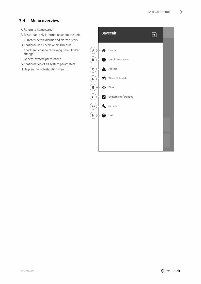
7.4 Menu overview
A.Return to home screen
B. Basic read-only information about the unit
C. Currently active alarms and alarm history
D. Configure and check week schedule
E. Check and change remaining time till filterchange
F. General system preferences
G.Configuration of all system parameters
H.Help and troubleshooting menu
211473 | A001

10 | SAVECair control
7.5 Home screen
Touching home icon (pos. A) in drop-down menu list (pos. 1) will always returns youto home screen after commissioning.
1. Drop-down menu list
2. Active user mode
3. Airflow settings
4. Temperature settings
5. List of active alarms
6. Icon list of active user functions
7.5.1 User modesThe first icon at the top of home screen shows currently active user mode. To change the user mode, touch the activeuser mode icon (pos. 2) and select a new user mode from the list. The unit has 2 permanent and 5 temporary usermodes available for selection. Only one mode can be active at a time.
Settings of all modes can be modified in Servicemenu.
7.5.1.1 Permanent modesPermanent modes are always active unless interrupted by temporary modes, activated user functions or alarms:
Icon Text Description
AUTO
Automatic airflow control. AUTO mode is available for selection when DemandControl, Week Schedule and/or external fan control functions are configured,otherwise AUTO mode icon won’t be visible in active user modes menu. AUTOmode activates Demand Control, Week Schedule and/or external fan controlfunctions. Demand is available to choose as airflow setting in Week Schedule.
MANUAL
Manual selection of airflow levels. The unit can be set run at one out of fouravailable airflow speeds: Off/Low/Normal/High.
Note:The fan can be set to OFF by activating Manual Fan Stop function inServicemenu.
7.5.1.2 Temporary modesTemporary modes are active only for a set period of time unless interrupted by active user modes, activated user func-tions or alarms:
211473 | A001

SAVECair control | 11
Icon Text Description
HOLIDAY
Sets speed of both supply and extract air fans to Low levels when user is awayfrom home for a long period of time.ECO mode is active.Delay in days.
CROWDED
Sets speed of both supply and extract air fans to maximum High levels andtemperature setpoint offset to –3 K when apartment is more crowded than usual.Default temperature setpoint offset is –3 K.Delay in hours.
AWAY
Sets speed of both supply and extract air fans to Low levels when user is awayfrom home for a short period of time.ECO mode is active.Delay in hours.
REFRESHSets speed of both supply and extract air fans to maximum High levels toreplace indoor air with a fresh air in a short period of time.Delay in minutes.
FIREPLACE
Sets speed of supply air fan to High level and extract air fan to Low level toincrease air pressure within the apartment for better smoke extraction throughthe chimney.Delay in minutes.
Settings of all modes can be modified in Servicemenu.
Temporary modes and user functions are active only for a set period of time after which they are terminated and theunit changes back to a former AUTO or MANUALmode, depending on which one was active before temporary mode oruser function was activated.
7.5.1.3 Digital input functionsDigital input functions always active while digital input is activated.
Icon Text Description
CentralVacuumCleaner
Function sets speed of supply air fan to High level and extract air fan to Lowlevel to increase air pressure within the apartment for better dust collectionthrough central vacuum cleaner.Function can be activated via digital input — Central Vacuum CleanerFunction.
Cooker Hood
Sets speed of supply air fan to High level and extract air fan to Low level toincrease air pressure within the apartment for better airborne grease and steamcollection in the kitchen.Function can be activated via digital input — Cooker Hood Function.
7.5.1.4 Digital input and Mode hierarchyUser modes and functions have a different hierarchy. User functions activated via HMI or mobile APP, such as AWAY,CROWDED, FIREPLACE, HOLIDAY and REFRESH, are interrupted by manual selection of AUTO and MANUAL fan modes.
A FIREPLACE function has the highest priority between user functions. Other functions activated via HMI/APP can in-terrupt each other.
If FIREPLACE function is hard-wired on the connection board and configured as digital input (DI) then it has a higherpriority than AUTO and MANUALmode. Digital input for a FIREPLACE function has also a higher priority than otherhard-wired digital inputs (DI) for: AWAY, CENTRAL VACUUM CLEANER, COOKER HOOD, CROWDED, HOLIDAY or REFRESH.
Digital input and Mode hierarchy:
1.EXTERNAL STOP
2.FIREPLACE function
3.COOKER HOOD, CENTRAL VACUUM CLEANER, CROWDED, REFRESH functions
4.AWAY, CROWDED functions
211473 | A001

12 | SAVECair control
7.5.2 Temperature settings
Temperature can be set at SET TEMPERATUREmenu accessible from the home screen by touchingTEMPERATURE icon with thermometer. Default temperature value is 18°C (range 12–30°C).
Use up and down arrows or a slider to change the value.
Then touch the SET to confirm changes.
Temperature set point is for room air temperature, supply air temperature or for extract air temperature depending onwhich control mode is active. Default setting is Supply air temperature control.
Control mode of the temperature can be changed in Servicemenu.
7.5.2.1 ECO mode
ECO mode is a power saving function that can be activated in SET TEMPERATUREmenu.
While ECO mode is active, a temperature setpoint at which heater is activated is lowered to avoid activation of the heat-er during cold nighttime.
If the temperature is very low and the heater is activated during the nighttime (even with lowered temperature set-point), then during the upcoming daytime indoor temperature will be increased using the heat exchanger so that accu-mulated heat could be used during the next cold nighttime, the lowered setpoint for the heater remains.
ECO mode will have impact for the following userfunctions/modes if selected: ECOmode is always activated by the following modes:
• AUTOmode
• MANUALmode
• AWAYmode
• HOLIDAYmode
• CENTRAL VACUUM CLEANER function
• COOKER HOOD function
• FIREPLACEmode
• AWAYmode
• HOLIDAYmode
ECO mode is always deactivated by the following userfunctions/modes:
• CROWDEDmode
• REFRESHmode
• FREE COOLING function
7.5.3 Airflow settings
Airflow settings are available only in MANUALmode. Click on fan icon on the main screen to enter SETAIRFLOWmenu.
Use up and down arrows or a slider to change the airflow value.
The airflow may be adjusted in these steps: Off/Low/Normal/High. These settings control output signals to the sup-ply and extract fans.
211473 | A001

SAVECair control | 13
ImportantIt is not recommended to set fan to Off in standard households. If manual fan stop is activated, the unitshould be provided with dampers in exhaust and fresh air ducts to avoid cold draught and risk ofcondensation when the unit has been stopped.The fan can be set to Off by activating Manual Fan Stop function in Servicemenu.
7.5.4 Indoor Air Quality
The unit automatically controls indoor humidity and/or CO2 levels by adjusting airflow setting. Airflow isincreased if air quality is decreasing.
Demand Control function is responsible for IAQ (Indoor Air Quality) regulation. Relative humidity (RH) and/or CO2 sen-sors are responsible for IAQ monitoring.
Indoor air quality (IAQ) indicator is available if AUTOmode and Demand Control function is activated.
IAQ levels:
• ECONOMIC: Actual IAQ value is below low IAQ set point.
• GOOD: Actual IAQ value is between low and high IAQ limits.
• IMPROVING: Actual IAQ value is above high IAQ set point.
Different airflow settings can be set for IMPROVING and GOOD IAQ levels in Servicemenu.
Setpoint for relative humidity and CO2 level can be set in Servicemenu.
7.5.5 Status lineStatus line located at the bottom area of home screen displays information about:
List of active alarms. Seechapter 7.7.2.3 for moreinformation.
List of active user functions.See chapter 7.6 for moreinformation.
Touching any of these lines will move you to the next page with more detailed list and information about each alarm oractive user function.
7.6 Description of User function icons
Icon Text Description
Heating Connected heater or pre-heater is active and air heating is in process.
Heat recovery Heat recovery from apartment is active.
Cooling Connected cooler is active and air cooling is in process.
Coolingrecovery
Automatic cooling recovery is active when extract air temperature fromapartment is lower than outdoor air temperature and there is a cooling demand(temperature setpoint is lower than outdoor air temperature).No cooling recovery with heating demand. If the outdoor air temperature ishigher than then thee indoor air temperature and there is a heating demand,function Free heating is activated instead.
Free cooling Function decreases indoor air temperature by using only cool outdoor air duringnighttime to save energy consumption.
Moisturetransfer
Function controls the rotation speed of the heat exchanger to prevent moisturetransfer to supply air due to high relative humidity in the extract air.Function is only available for units with Rotating type heat exchanger.
211473 | A001

14 | SAVECair control
Icon Text Description
Defrosting Function prevents formation of the ice on the heat exchanger during coldoutdoor temperatures.
Secondary air
Warm air from the living space is used to defrost the heat exchanger using adamper inside the outdoor air duct. The unit switches from outdoor air tosecondary air while the extract air fan stops and warm secondary air increasesthe temperature inside the heat exchanger.
Vacuumcleaner
Function sets speed of supply air fan to High level and extract air fan to Lowlevel to increase air pressure within the apartment for better dust collectionthrough central vacuum cleaner.Function can be activated via digital input — Central Vacuum CleanerFunction.Always active while digital input is activated.
Cooker hood
Sets speed of supply air fan to High level and extract air fan to Low level toincrease air pressure within the apartment for better airborne grease and steamcollection in the kitchen.If a cooker hood with integrated fan is used, then it is recommended to setairflow levels of both fans to Normal.Function can be activated via digital input — Cooker Hood Function.Always active while digital input is activated.
User lockFunction indicates that the system is locked with a password and cannot beedited or settings changed in any way. System must be unlocked first to makechanges.
7.7 Main menu
User settings and advanced settings
7.7.1 Unit Information
A basic read-only information about status of the unit, configured components and inputs/outputs.
211473 | A001

SAVECair control | 15
7.7.1.1 Components
Type and settings of heat exchanger, heater, cooler, extra controller.
7.7.1.2 Sensors
Values from sensors and load of fans (rpm).
7.7.1.3 Input Status
Status of configured analog, digital and universal inputs. Connected component type and raw value (volts) is displayed.
7.7.1.4 Output Status
Status of configured analog, digital and universal outputs. Connected component type and value (volts) is displayed.
7.7.1.5 Unit Version
Unit model name, manufacturer number, serial number and unit software versions for Mainboard, HMI and IAM.
7.7.2 Alarms
A detailed information about active system alarms and alarm log of last 20 events.
7.7.2.1 Active Alarms
Alarm screen is empty if there are no active or logged alarms.
Press HELP button on the active alarm to access FAQ and troubleshooting (if available). Press ACKNOWLEDGE on the in-dividual alarm to clear it. Depending on alarm type and the cause, it might be necessary to do a troubleshooting first toacknowledge active alarm.
It may be not possible to clear the status of alarm if the cause of alarm is still present, as that would immediately triggeralarm to return.
7.7.2.2 Alarms log
Alarm log allows to view last 20 alarms.
Each alarm contains information:
• Alarm name
• Date/time stamp
• Information if the alarm stops the unit or other note
7.7.2.3 Alarm list
Alarm name Explanation Do the following
Frost protection Frost protection of return water inheating coil.
• Alarm stops the unit and opensthe water valve completely.
The alarm will reset once the watertemperature reaches 13°C.Check the water fluid temperature inheating coil.Check the circulation pump of waterheater. Contact your installationcompany or place of purchase.
Frost protection temperaturesensor
Indicates malfunction of waterheater temperature sensor.
• Alarm stops the unit.
Check that frost protectiontemperature sensor is connectedproperly and cable is not damaged.Contact your installation company orplace of purchase.
211473 | A001

16 | SAVECair control
Alarm name Explanation Do the following
Defrosting error Indicates failure of pre-heater topreheat the incoming outdoor air (incase Extra controller is configured asPreheater).
• Alarm stops the unit.
Check the pre-heater reset button.Check the pre-heater cabling.Contact your installation company orplace of purchase.Defrosting error may be caused byextremely low outdoor airtemperatures or pre-heater failure.
Supply air fan rpm Rotation speed of the supply air fanis lower than minimum required. Fanmalfunction.
• Alarm stops the unit.
Check quick connectors of the fan.Contact your installation company orplace of purchase.
Extract air fan rpm Rotation speed of the extract air fanis lower than minimum required. Fanmalfunction.
• Alarm stops the unit.
Check quick connectors of the fan.Contact your installation company orplace of purchase.
Supply air fan control error Flow or pressure alarm for supply air.The pressure is bellow pressure limit.
• Alarm stops the unit.
Check that air tube for pressuresensor is connected properly andcable is not damaged.Contact your installation company orplace of purchase.
Extract air fan control error Flow or pressure alarm for extractair. The pressure is bellow pressurelimit.
• Alarm stops the unit.
Check that air tube for pressuresensor is connected properly andcable is not damaged.Contact your installation company orplace of purchase.
Fire alarm Fire alarm is active.
• Alarm stops the unit.
Once the external Fire alarm isdisabled – alarm has to beacknowledged and unit restarted.
Emergency thermostat Indicates triggered overheatprotection (in case of installedelectric re-heater battery).
A triggered manual or automaticoverheat protection (EMT) gives analarm in the control panel.In case a manual overheat protectionis triggered, reset it by pushing thereset button.If the automatic overheat protectionis triggered, it will resetautomatically once the temperaturehas dropped.If the problem continues contactyour installation company or place ofpurchase.
Bypass damper Indicates malfunction in bypassdamper.
Disconnect the main power supplyfor 10 seconds to reset controlfunction.Power up the unit, an automaticbypass damper test will beperformed.If the alarm occurs again afterapproximately 2 minutes – contactyour installation company or place ofpurchase.
211473 | A001

SAVECair control | 17
Alarm name Explanation Do the following
Rotor guard Indicates a rotor malfunction.No rotation guard signal for 180seconds.
If the rotating heat exchanger hasstopped. Check the rotor belt.If the heat exchanger is still rotating,check that the quick connector forthe sensor is connected and thatthere is an air gap of 5-10 mmbetween the sensor and the magnet.Adjust the gap if necessary.If the alarm persists, the rotor sensormay be faulty. Contact yourinstallation company or place ofpurchase.
Secondary air damper Secondary air defrosting failed.Outdoor air temperature sensormeasures < 10°C in 2 sec afterdefrostingOROutdoor air temperature sensormeasures < 5°C in 5 min afterdefrosting
Check if secondary air damper is incorrect position.Check that damper is connectedproperly and cable is not damaged.Contact your installation company orplace of purchase.
Outdoor air temperaturesensor
Indicates outdoor air temperaturesensor malfunction.
Check that sensor is connectedproperly and cable is not damaged.Contact your installation company orplace of purchase.
Overheat temperature sensor Indicates overheat temperaturesensor malfunction.
Check that sensor is connectedproperly and cable is not damaged.Contact your installation company orplace of purchase.
Supply air temperaturesensor
Indicates supply air temperaturesensor malfunction.
Check that sensor is connectedproperly and cable is not damaged.Contact your installation company orplace of purchase.
Room air temperature sensor Indicates room air temperaturesensor malfunction.
Check that sensor is connectedproperly and cable is not damaged.Contact your installation company orplace of purchase.
Extract air temperaturesensor
Indicates extract air temperaturesensor malfunction.
Check that sensor is connectedproperly and cable is not damaged.Contact your installation company orplace of purchase.
Extra controller temperaturesensor
Indicates extra controllertemperature sensor malfunction.
Check that sensor is connectedproperly and cable is not damaged.Contact your installation company orplace of purchase.
Efficiency temperaturesensor
Indicates efficiency temperaturesensor malfunction.
Check that sensor is connectedproperly and cable is not damaged.Contact your installation company orplace of purchase.
PDM RH Indicates internal relative humiditysensor malfunction.Active: measured humidity = 0%Returned: measured humidity > 5%
Check that sensor is connectedproperly and cable is not damaged.Contact your installation company orplace of purchase.
PDM RH Extract airtemperature
Indicates internal extract airtemperature sensor malfunction.Active: measured temperature = 0°CReturned: measured temperature >5°C
Check that sensor is connectedproperly and cable is not damaged.Contact your installation company orplace of purchase.
211473 | A001

18 | SAVECair control
Alarm name Explanation Do the following
Filter Time for filter change. Change the filter.Change filter according to theinstructions in the User Manual.Details about filter retailers can befound in Help menu.
Extra controller alarm Error from external device. Check if external device is connectedproperly and cable is not damaged.Reset overheat protection onelectrical pre-heater. Contact yourinstallation company or place ofpurchase.
External stop Unit is stopped by external signal. Operation is stopped by digital signalfrom external remote device orsignal from building managementsystem.
Manual fan stop active Operation stopped, fans are inmanual mode and selected as OFF.
Select another speed of fans (LOW /NORMAL / HIGH) or AUTOmode inHMI home screen.
Overheat temperature Temperature after reheater is toohigh.Active: (Overheat temperaturesensor measures > 55°C)Returned: (Overheat temperaturesensor measures < 50°C)
Alarm is possible if supply airflow istoo low when the reheater isswitched on.Check the supply airflow.Check that intake grille is notblocked.Check that shut off damper foroutdoor air is open in operation.Contact your installation company orplace of purchase.
Low supply air temperature Supply air temperature is too low.Active: (Outdoor air temperaturesensor measures < 0°C) AND (Supplyair temperature sensor measures <5°C)Returned: (Supply air temperaturesensor measures > 10°C)
Check the heat exchanger and re-heater or refer to Point 2 in“Troubleshooting” menu.
CO₂ External CO2 sensor malfunction. Check that sensor is connectedproperly and cable is not damaged.In case sensor wireless – checkRS485 gateway status and sensorstatus in HMI.Contact your installation company orplace of purchase.
RH External relative humidity sensormalfunction.
Check that sensor is connectedproperly and cable is not damaged.In case sensor wireless – checkRS485 gateway status and sensorstatus in HMI.Contact your installation company orplace of purchase.
Output in manual mode One or more of analogue outputs arein manual mode.
Check Service menu for Outputsettings, and check all configuredoutputs to be in Auto mode. If anyoutputs in Manual - change back toAuto mode.
7.7.3 Week Schedule
The unit can be configured to operate at set airflow levels up to two time periods (00:00–23:59) on userselected days.Week Schedule is active only during AUTOmode.
211473 | A001

SAVECair control | 19
7.7.3.1 Schedule airflow settings
Touch settings icon to go to SCHEDULE AIRFLOW SETTINGSmenu. In this menu set airflow level forscheduled and unscheduled periods. Available levels: Off, Low, Normal, High or Demand.Set temperature setpoint offset for both periods (-10°C – 0°C).
Demand level is available only if Demand Control or External fan function is active.
7.7.3.2 Edit schedule
Touch icon at the bottom left corner of the screen to add a new schedule or press EDIT button to modifyalready added schedule.
To configure the schedule:
1. Set the time. Touch the START TIME or END TIME values to change time. Use arrow buttons and to increaseor decrease value. Confirm with OK button.
Note:Scheduled time can start but never end at midnight (00:00). The latest END TIME period is 23:59.Scheduled time cannot go to the next day.
If necessary, activate second scheduled period and set up time.
2. Once time is set, click on the day(s) when schedule should be active. It is possible to set a separate schedule for eachday.
Already scheduled days are not available for selection for new schedules.
3. Confirm schedule with OK button.
Fig. 3 Week schedule example
Scheduled days are highlighted (pos. 1). First time period (pos. 2) and the second time period (pos. 3) are shown on theright side of each schedule.
Scheduled time period is displayed in blue colour on the clock (pos. 4).
7.7.4 Filter
In this menu the remaining time until filter change is displayed. Editing is locked with a password, useadministrator password. See Password Settings in Servicemenu for more information.
Set duration of the filter until next change for period of 3–15 months in steps of 1 month. Default setting is 12 months.
If a new filter period is selected and confirmed or filter alarm is acknowledged, the timer resets and starts counting fromthe beginning.
Information what filter type is needed for change or where to order a new filter can be found in Helpmenu.
211473 | A001

20 | SAVECair control
7.7.5 System Preferences
Configuration of unit location, language and time.
Change the following information:
• Language (default language is English)
• Country (default country is UK)
• Unit address (address, post code)
• Unit date and time, activate or deactivate summer/winter time switch.
Time will automatically change between summertime and wintertime according to European standard, based onGreenwich time zone and set unit location.
Switch between 12 and 24 hours time format.
• Contact information: contractor, installer, service, phone, website, e-mail, etc.
• Display settings: screen brightness and screen behavior in standby mode.
7.7.6 Service
All unit parameters and settings can be changed in the Servicemenu.The Servicemenu is locked by default and it is necessary to enter a password (defaultpassword is 1111).
7.7.6.1 Input
Configuration of inputs
Settings for analog, digital and universal input terminals on the main board, configuration of functionality.
Relative humidity and rotation speed signals from fans are already pre-addressed to specific terminals and cannot bechanged, all other inputs are free for configuration by commissioning. Inputs are free to be used for any purpose.
Digital inputs are restricted by signal type and physical number of connections. An input function is only allowed to beused once.
Universal input (UI) configured as universal analog input (UAI) can be configured for several inputs because multiplesensors of the same type can be used. Universal analog inputs (UAI) have only selections for RH Sensor (RH), CO₂Sensor (CO₂), Supply Air Fan Control (SAFC) and Extract Air Fan Control (EAFC) wired configurations.
Analog input (AI) temperature sensors are not allowed to be configured more than once.
Already used and configured input signal type is greyed out and not available for selection. However some user func-tions related to configuration of digital input (AWAY, CROWDED, FIREPLACE, HOLIDAY or REFRESH) have several possi-ble activation points, via HMI/APP/Wireless/Modbus (BMS).
Digital inputs can be configured to be normally open (Normally Open (NO)) or normally closed (Normally Closed(NC)). Default setting is Normally Open (NO). Not available for wireless inputs.
PDM (pulse density modulation) input for relative humidity (RH) sensor on the main board is pre-adressed and cannotbe changed.
Table 2 Overview of input configuration
Analog inputs Digital inputs Universal analog inputs Universal digital inputs
Input typeValueCompensation
Input typePolarityValue
Input typeAnalog typeValue
Input typeDigital typePolarityValue
211473 | A001

SAVECair control | 21
7.7.6.2 Output
Configuration of outputs.
Settings for analog, digital and universal output terminals on the main board and connection board, configuration offunctionality.
Fan output PWM (Pulse-width modulation) signal and triac output are already pre-addressed to specific terminals andcannot be changed, all other outputs are free for configuration by commissioning. Outputs are free to be used for anypurpose.
Digital outputs are restricted by signal type and physical number of connections.
An output function is only allowed to be used once. Already used and configured terminal is greyed-out in the menu foroutput type selection.
Analogue and digital outputs have a selection for Auto/Manualmodes and an adjustable value for Manualmode.
Manualmode selection overwrites all system related automatic functions. Analogue output adjustable manual valuerange is 0–10V and digital output values On/Off.
Table 3 Overview of output configuration
Analog outputs Digital outputs
Output typeAuto/ManualValue
Output typeAuto/ManualValue
7.7.6.3 Components
Configuration of connected components.
Heat Exchanger
• Choose heat exchanger type.
Available types: Rotating / Plate
• Activate or deactivate passive house function if heat exchanger type Rotating is selected.
Options: Yes / No.
• Choose bypass damper location if heat exchanger type Plate is selected. Default setting is based on unit type.
Supply / Extract
• Set actuator type. Default setting is based on unit type.
Range: 0–10 V / 2–10 V / 10–0 V / 10–2 V.
Heater
• Choose heater type. Each selection unlocks additional configuration options. Default setting is based on unit type.
Available types: None / Electrical / Water / Change-over.
• Set actuator type. Default value is 0–10 V.
Range: 0–10 V / 2–10 V / 10–0 V / 10–2 V.
• Set circulation pump temperature. Default setting is 10°C. This option is available if Water / Change-over heatertype is selected.
Range: 0–20°C.
• Set circulation pump stop delay. Default setting is 5 minutes. This option is available if Water / Change-over heat-er type is selected.
Range: Off / 1–60 min.
Cooler
• Choose cooler type. Each selection unlocks additional configuration options. Default setting is None.
Available types: None / Water / Change-over.
211473 | A001

22 | SAVECair control
• Set outdoor air temperature interlock. Default setting is 10°C.
Range: 0–20°C.
• Set actuator type. Default value is 0–10 V
Range: 0–10 V / 2–10 V / 10–0 V / 10–2 V.
• Set circulation pump stop delay. Default setting is 5 minutes. This option is available if Water / Change-over heat-er type is selected.
Range: Off / 1–60 min.
Extra controller
• Choose extra controller type. Each selection unlocks additional configuration options. Default setting is None.
Available types: None / Preheater / Heating / Cooling.
• Set temperature set point of the extra controller. Default value is 0°C.
Range: –30°C— 40°C.
• Set P-band. Default setting is 4°C.
Range: 1-60°C.
• Set I-time. Default setting is Off.
Range: Off / 1–240 sec.
• Set actuator type. Default value is 0–10 V.
Range: 0–10 V / 2–10 V / 10–0 V / 10–2 V.
• Set circulation pump temperature. Default setting is 0°C. This option is available if Preheater / Heating controllertype is selected.
Range: 0–20°C.
• Set circulation pump stop delay. Default setting is 5 minutes.
Range: Off / 1–60 min.
7.7.6.4 Control Regulation
Configure how the system is controlled.
Temperature Control
• Configure temperature controller. Choose control mode:
Available modes: Supply air temperature control / Room temperature control / Extract air temper-ature control
• Choose temperature unit. Default setting is Celsius.
Available units: Celsius / Fahrenheit
• Set P-band. Default setting is 20°C. Set I-time. Default setting is 100 sec.
• Configure SATC Split for heater (0–20%), heat exchanger (25–60%) and cooler (65–100%) output settings.Range: 0–100%.
• Configure cascade control setpoint for min/max supply air temperature, P-band, I-time.
Only available for Room temperature control / Extract air temperature controlmodes.
ECO mode
• Configure ECO mode settings. Set heater offset. Default setting is 10°C.
Range: 0–10°C.
Fan Control
• Configure airflow and fan settings. Select fan control (airflow) type. Default setting is Manual (%).
Available types: Manual (%) / Manual rpm / Flow (CAV) / Pressure (VAV) / External
211473 | A001

SAVECair control | 23
Setting Manual RPM Flow (CAV)Pressure(VAV) External
Airflowmeasurementunit.
% rpm l/s, m3/h, cfm Pa, inwc %
P-Band 0–100% 0–3000 rpm 0–500 PaDefault setting: 150 Pa
0–100%
I-time Off / 1–240 sec. Off / 1–240 sec.Default setting:50 sec.
Off / 1–240 sec.Default setting: 50 sec.
Off / 1–240 sec.
Airflow levelsettings for eachlevel: MAXIMUMLEVEL, HIGHLEVEL, NORMALLEVEL, LOWLEVEL,MINIMUM LEVEL
16-100% 500–5000 rpm Sensor range (airflow unit) 0–100%
Manual Fan Stop — turn on or off manual fan stop, this function enables manual fan stop from HMI. Default settingis OFF.PressureSensors —configure sensorvoltage relationto pressure.Set value atwhich fan alarmoccurs. Defaultsetting is None
- - Supply air fan control sensor:Pressure at 0V: 0-500 Pa, defaultsetting 0 PaPressure at 10V: 0-2500 Pa, defaultsetting 500 Pa.Extract air fan control sensor:Pressure at 0V: 0-500 Pa, defaultsetting 0 Pa.Pressure at 10V: 0-2500 Pa, defaultsetting 500 Pa
-
Set K factor forsupply air fanand extract airfan. Defaultsettings arebased on unittype.
- - SAF K-Factorrange: 0–1000EAF K-Factorrange: 0–1000
- -
OutdoorCompensation
Compensation is always started at fixed value of 0° C. Set stop compensation for outdoor airtemperature and compensation value for fan speed.Stop Compensation Temperature range: -25 - 0°C, default setting 0°CStop Compensation Value range: -50 to 0%, default setting 0%
ImportantChanging the airflow type does not change P-band value automatically. P-band value have to be changedmanually after changing the airflow type.
Demand Control
Configure indoor air quality sensors. Once sensor(s) are configured, Demand Control function is activated by choosingAUTOmode in home screen.
• Activate or deactivate CO2 sensor. Default setting is Off.
Set CO2 sensor setpoint. Default setting is 800 ppm (parts per million in atmosphere). Normal atmospheric CO2 con-centration is 400 ppm. Range: 100–2000 ppm.
Set P-band, default setting is 200 ppm. Range: 50–2000 ppm.
Set I-Time, default setting is Off. Range: Off/1–120 sec.
• Activate or deactivate RH sensor. Default setting is Off.
Set humidity setpoint in summer, default setting is 60%. Range: 1–100%.
Set humidity setpoint in winter, default settting is 50%. Range: 1–100%.
Set P-band, default setting is 10%. Range: 1–100%.
211473 | A001

24 | SAVECair control
Set I-time, default setting is Off, Range: Off/1–120 sec.
• Select airflow level for Improving Air Quality. Range: Normal / High / Max.
• Select airflow level for Good Air Quality. Range: Low / Normal.
RH Transfer Control
Note:Setting is available if heat exchanger type is set as Rotating. It is highly recommended to leave defaultvalues for P-band and I-time. They should be changed only by installer and trained staff.
• Activate or deactivate relative humidity transfer functionality. Default setting is On.
• If RH Transfer Control is activated, configure:
Setpoint, default setting is 45% humidity. Range: 1–100% RH.
Set P-band, default setting is 4g/kg. Range: 1–100g/kg.
Set I-time, default setting is Off. Range: Off/1–120 sec.
Defrosting Control
Note:Setting is available if heat exchanger type is set as Plate.
The unit is equipped with an automatic defrost function that is activated when there is risk of icing in the area aroundthe heat exchanger.
• Select defrosting mode. Default setting is Normal.
SoftDry areas, such as warehouse buildings with few people or industrialbuildings that don’t use water in their production process.
Normal Apartments or houses with normal humidity 1
Hard Buildings with very high humidity level.
1 In newly constructed houses it might be necessary with a higher defrost level during the first winter period.
• Set by-pass location. Default setting is based on unit configuration.
Supply / Extract.
• Set preheater setting. Default setting is based on unit configuration.
Auto / Fixed
Fixed pre-heater setting allows user to adjust pre-heater setpoint manually. Auto pre-heater setting sets floatingpre-heater activation setpoint (Stop defrosting temperature +2K).
• Set if secondary air is allowed. Default setting is Off.
Off / On.
Cooling Control
• If the outdoor air is warmer than the extract air and the supply air is above the setpoint, cooling recovery occurs. Thiscondition blocks the heat regulation process. Activate or deactivate cooling recovery. Default setting is On.
Set cooling limit. Cooling recovery is allowed if extract air temperature is lower than outdoor air temperature by a setlimit (default setting is 2K) and cooling demand is present.
• Configure status, temperature and duration of free cooling. Activate or deactivate free cooling . Default setting isOff.
Set supply and extract air fan levels during free cooling. Default setting is Normal. Range: Normal / High /Maximum.
Set start condition. Outdoor daytime temperature for activation, default setting is 22°C. Range: 12–30°C.
Stat stop conditions. Extract/Room temperature, default setting is 18°C. Outdoor high temperature limit, default set-ting is 23°C. Outdoor low temperature limit is 12°C. Start and stop time.
211473 | A001

SAVECair control | 25
7.7.6.4.1Finding RPM for desired airflowIt is necessary to set fan RPM (revolutions per minute) for each airflow level to control airflow by changing fan speed.Fan speed differ for each household because of different unit size, duct system and system pressure. In order to findcorrect fan speed, external tool must be used at Systemair website.
1. Go to Systemair website and find your unit.
2. Go to Diagram tab and type in desired airflow values in l/s, m3/h, m3/s or cfm for supply and extract air. Input pres-sure drop in duct system (if this value is not know, type in 100 Pa for both supply and extract air)
Fig. 4 Example of airflow and external pressure selection
3. See calculated speed values in revolutions per minute (rpm) for both supply and extract air in the table bellowdiagrams.
Fig. 5 Example speed for supply and extract air
4. Use this procedure to find fan speed for all airflow levels: MINIMUM LEVEL, LOW LEVEL, NORMAL LEVEL, HIGH LEV-EL, MAXIMUM LEVEL.
5. Finally in the control panel go to Servicemenu, enter the password, then go to Control Regulation→ FanControl. Choose RPM as airflow type and in sub-menu Airflow Level Settings enter calculated fan speed val-ues for each level.
7.7.6.5 User Modes
Set airflow level, duration and offset for each user mode.
Set supply and extract air fan levels, default duration and temperature offset where available for user modes:
• Away
• Central Vacuum Cleaner
• Cooker Hood
• Crowded
• Fireplace
• Holiday
• Refresh
7.7.6.6 Communication
Configure Modbus and wireless settings
Modbus
• Set Modbus address. Default setting is 1.
• Set baud rate. Default setting is 19200.
• Set parity. Default setting is None. Range: None / Even / Odd.
• Set stop bits. Default setting is 2. Range: 1–2.
• Shows Smartly-Gateway state.
211473 | A001

26 | SAVECair control
HMI
• Shows communication information for HMI. Modbus device number (1–10) and Modbus termination: Active/Inactive.
7.7.6.7 Logs
Information about alarms, fans and parameters are stored in Logsmenu.
Fans Levels
• Time counter for each supply air fan level duration is displayed. Counted and total time. Reset counted time.
Level 1: 0%
Level 2: 1–29%
Level 3: 30–44%
Level 4: 45–59%
Level 5: 60–100%
Parameters
• Select parameter type and create a graph based on stored data . Export parameters data by touching arrow
button . (only available in mobile application)
7.7.6.8 Unit Backups
In this menu it is possible to save and restore user and factory settings.
User backups
• Touch SAVE button to save current configuration and parameters.
Touch RESTORE button to restore last saved user configuration and parameters
Factory settings
• Touch RESTORE button to restore factory configuration and parameters. This will also overwrite changed password.
Software versions
Displays current version of main circuit board, Internet Access Module and HMI.
• Touch SOFTWARE UPDATE button to update software if there is a newer version.
7.7.6.9 Password Settings
Service level is always locked with a password. Other menu levels have a separate option for locking. If password re-quirement is activated for different menu levels, these are unlocked with the administrator password.
Choose what menus should be locked or not.
7.7.7 Help
FAQ, troubleshooting of alarms, contact information for support is provided in this menu.
• Service partner — information about service partner.
• Company
• Telephone
• Homepage
• User modes— detailed description of all user modes.
• Functions— detailed description of different user functions.
211473 | A001

Electrical connections | 27
• Alarms— detailed description of all alarms.
• Troubleshooting— information about all different possible malfunctions.
8 Electrical connectionsThe SAVE VTR 250/B is wired internally from factory.The electrical connection box can be found on the supply air outlet side of the unit. The print card can easily be takenout from the unit, without using tools.
Fig. 6 Print card position
8.1 Main board layoutThe SAVE VTR 250/B is equipped with built-in regulation and internal wiring.
The figure shows the main circuit board. See wiring diagram for more information.
211473 | A001

28 | Electrical connections
Fig. 7 Main circuit board connections
Position Description
MB Main circuit boardCB Connection to the external connection box1 Terminals for a heater2 Terminals for a TRIAC3 Terminals for the mains power supply
4 Terminals for power supply of extract air fan
5 Terminals for power supply of supply air fan
6 Terminals for internal relative humidity/temperature sensor
7 Analog input 1 — Outdoor air sensor
8 Analog input 2 — Supply air sensor
9 Analog input 3 — Freely configurable
10 Analog input 4 — Freely configurable / Overheat temperature sensor (units withheater)
11 Analog input 5 — Freely configurable
12 Digital input 1 — Rotor guard sensor (VSR, VTR units)/ Damper signal (VTC units)
13 Digital input 2 — Freely configurable / Cooker hood (VTR 150/K unit)
14 Analog output 2 — Freely configurable / Electrical heater controller (VTC 700 unit)
15 Analog output 1 — Rotor of the heat exchanger (VSR, VTR units) / Damper control(VTC units)
16 Terminals for speed control of extract air fan
17 Terminals for speed control of supply air fan
211473 | A001

Before starting the system | 29
8.2 External connections (Connection board)External connections to the main circuit board are done via connection board situated outside of the unit.
Fig. 8 External connection box and board
Position Description
1 Connection to the main circuit board2 Connection for external control panel (HMI) or Internet access module (IAM)
3 Modbus RS485 connectionAI6–7 Freely configurable Analog input. None/Input type selection in HMI.
DO1–4 Freely configurable Digital output. None/Output type selection in HMI.
AO3–5 Freely configurable Analog output. None/Output type selection in HMI. Actuator type 0–10V, 10–0V, 2–10V, 10–2V.
UI1–5 Freely configurable Universal input. Can be configured to act as Analogue input (0–10V) or asDigital input (24V). None/Input type selection in HMI (NC or NO polarity).
24V Maximum current 200mA at 24VDC +-10%.
9 Before starting the systemWhen the installation is finished, check that:
• The unit is installed in accordance with the instructions
• The unit is correctly wired
• Outdoor and exhaust air dampers and silencers are installed and that the duct system is correctly connected to theunit
• All ducts are sufficiently insulated and installed according to local rules and regulations
• Outdoor air intake is positioned with sufficient distance to pollution sources (kitchen ventilator exhaust, central vac-uum system exhaust or similar)
• All external equipment are connected
• The unit is correctly configured and commissioned
• The week schedule and airflow settings are correctly programmed.
211473 | A001

30 | Service
10 Service
10.1 Warnings
Danger• Make sure that the mains supply to the unit is disconnected before performing any maintenance or
electrical work!
• All electrical connections and maintenance work must be carried out by an authorized installer and inaccordance with local rules and regulations.
Warning• This product must only be operated by a person who has suitable knowledge or training within this field
or carried out with the supervision of a suitably qualified person.
• Beware of sharp edges during mounting and maintenance. Use protective gloves.
Warning• All though the mains supply to the unit has been disconnected there is still risk for injury due to rotating
parts that have not come to a complete standstill.
Important• The installation of the unit and complete ventilation system must be performed by an authorized installer
and in accordance with local rules and regulations.
• The system should operate continuously, and only be stopped for maintenance/service.
• Do not connect tumble dryers to the ventilation system.
• Duct connections/duct ends must be covered during storage and installation.
• Make sure that filters are mounted before starting the unit.
211473 | A001

Service | 31
10.2 Internal components
Fig. 9 Internal components
Position Description
1 Mounting bracket
2 External connections3 Extract air fan4 Supply air filter
5 Extract air filter6 Main print card
7 Rotating heat exchanger
8 Supply air fan
9 Supply air sensor
10 Outdoor air sensor11 Relative humidity/Extract air temperature sensor
12 Overheat protection sensor
13 Internal electrical re-heater
10.2.1 Component descriptions
10.2.1.1 FansThe fans have external rotor motors of EC type which can be steplessly controlled individually 16–100%. The motorbearings are life time lubricated and maintenance free. It is possible to remove the fans for cleaning, see “User Manual”for more information.
211473 | A001

32 | Service
10.2.1.2 FiltersThe factory installed filters are of filter quality F7 for the supply air and G3 for the extract air filter. The filters need to bereplaced when polluted. New sets of filters can be acquired from your installer or wholesaler.
10.2.1.3 Heat exchangerSAVE VTR 250/B is equipped with a highly efficient, rotating heat exchanger. Required supply air temperature is there-fore normally maintained without adding additional heat.
The heat exchanger is removable for cleaning and maintenance, see “User Manual” for more information.
10.2.1.4 Main circuit boardThe main circuit board controls all functions and the unit.
It is possible to connect external accessories to a free terminals on the main circuit board.
10.2.1.5 Connection boxConnection box is placed outside of the unit. It contains connection board. All external accessories can be connected tothe unit via connection board with freely configurable terminals.
10.2.1.6 Temperature sensorsFour temperature sensors (NTC, 10 kΩ at 25°C) are included in the unit from factory and positioned in the correspond-ing air chambers.
The sensors are connected to the main print card. See wiring diagram for more information.
10.2.1.7 Humidity sensorRelative humidity sensor (RH) is included in the unit at factory and positioned in the extract air chamber.
The sensor is connected to the main circuit board. See wiring diagram for more information.
10.2.1.8 Electrical Re-heater batteryThe re-heater battery is positioned in the supply air chamber.
The re-heater is activated by a relay and switches on if the supply air temperature is lower than the set point andswitches off if one or more of the following conditions are met:
1. If the supply air temperature is above the set point.
2. If the over heat protection is activated or the sensor is malfunctioning.
3. If the emergency thermostat is triggered or broken.
4. If the supply air sensor is in error state.
5. If the supply air fan is not running.
6. If the heater is set to disabled in the menu.
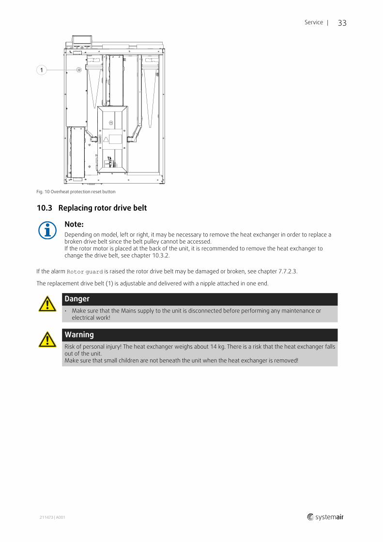
10.2.2 Overheat protection reset buttonIf the supply air temperature is low, it can indicate that the over heat protection is triggered. The overheat protectioncan be reset by pressing the reset button (1).
211473 | A001
Service | 33
Fig. 10 Overheat protection reset button
10.3 Replacing rotor drive belt
Note:Depending on model, left or right, it may be necessary to remove the heat exchanger in order to replace abroken drive belt since the belt pulley cannot be accessed.If the rotor motor is placed at the back of the unit, it is recommended to remove the heat exchanger tochange the drive belt, see chapter 10.3.2.
If the alarm Rotor guard is raised the rotor drive belt may be damaged or broken, see chapter 7.7.2.3.
The replacement drive belt (1) is adjustable and delivered with a nipple attached in one end.
Danger• Make sure that the Mains supply to the unit is disconnected before performing any maintenance or
electrical work!
WarningRisk of personal injury! The heat exchanger weighs about 14 kg. There is a risk that the heat exchanger fallsout of the unit.Make sure that small children are not beneath the unit when the heat exchanger is removed!
211473 | A001

34 | Service
Fig. 11 Rotor drive belt
10.3.1 Heat exchanger mounted1. Stop the unit by disconnecting the mains.
2. Open the front hatch.
3. Remove the broken drive belt.
4. Use tape to attach the drive belt to the rotating heat exchanger, and rotate the exchanger by hand to get hold of thedrive belt.
5. Remove the tape and put the ”empty” end on to the nipple.
6. Press the drive-belt ends firmly towards each other to secure the nipple.
7. Pull the drive belt on to the belt pulley and rotate the exchanger by hand. Check that the belt pulley rotates.
Note:If the drive belt slips, the drive belt may be too long and needs to be shortened. Cut the drive belt 5 mmand go to step 6.
8. Close and lock the front hatch and connect the unit to mains.
9. Check that the alarm has ceased on the Control Display.
Note:If the alarm remains, check the rotor sensor.
10.3.2 Heat exchanger removed1. Stop the unit by disconnecting the mains.
2. Open the front hatch.
3. Disconnect the heat exchanger power supply and the rotor sensor. The cables are found beside the heat exchangerat the back.
4. Pull out the heat exchanger towards you. Some force may be needed.
5. Remove the broken drive belt.
6. Apply the new drive belt around the heat exchanger.
7. Press the drive-belt ends firmly towards each other to secure the nipple.
8. Pull the drive belt on to the belt pulley and rotate the exchanger by hand. Check that the belt pulley rotates.
211473 | A001

Troubleshooting | 35
Note:If the drive belt slips, the drive belt may be too long and needs to be shortened. Cut the drive belt 5 mmand go to step 7.
9.Mount the heat exchanger. Don’t forget to reconnect the rotor power and sensor cables.
10.Close the front hatch and connect the unit to mains.
11.Check that the alarm has ceased on the Control Display.
Note:If the alarm remains, check the rotor sensor.
11 TroubleshootingIf problems should occur, please check the items below before calling your service representative.
Malfunction Action
Fans do not start
1. Check the HMI for alarms.
2. Check that all fuses and fast couplings are connected (main power supply and fastcouplings for supply and extract air fans).
3. Check that the week schedule is ON and running in AUTOmode. The week schedulemight be in OFFmode with the air flow set to OFF (chapter 7.7.3).
Reduced airflow
1. Check the HMI for alarms. Some alarms can reduce the airflow to LOW if active.
2. The unit could be in defrost mode. This reduces the fan speed and in some cases shutsdown the supply air fan completely during the defrosting cycle. The fans go back tonormal after finished defrosting. There should be a defrosting function icon visible in theAPP or HMI home screen if defrosting is active.
3. If the outdoor air temperature is below 0°C (Outdoor air temperature sensor (OAT)measures < 0°C) outdoor airflow compensation function can be active (if enabled). Fanspeed (Supply or Supply/Extract air fans) is linearly reduced for decreasing outdoor airtemperature.
4. Check if temporary user mode that reduces airflow is not activated, for example AWAY,HOLIDAY, etc. Also check digital inputs CENTRAL VACUUM CLEANER and COOKER HOOD.
5. Check setting of airflow in the HMI.
6. Check week schedule settings (chapter 7.7.3).
7. Check filters. Is change of filters required?
8. Check diffusers/louvres. Is cleaning of diffusers/louvres required?
9. Check fans and heat exchange block. Is cleaning required?
10.Check if the buildings air intake and roof unit (exhaust) have been clogged.
11.Check visible duct runs for damage and/or build up of dust/pollution.
12.Check diffuser/louvre openings.
The unit cannot becontrolled (controlfunctions are stuck)
1. Reset control functions by pulling out the plug for 10 seconds.
2. Check the modular contact connection between the HMI and the main printed circuitboard.
211473 | A001

36 | Troubleshooting
Malfunction Action
Low supply airtemperature
1. Check the display for alarms.
2. Check the active user functions in HMI screen if Defrosting function is running.
3. Check set supply air temperature in the HMI.
4. Check if ECOmode is activated in HMI (it is a power saving function and prevents theheater from activating).
5. Check if user modes HOLIDAY, AWAY or CROWDED are activated in the HMI or via ahardwired switch.
6. Check the analogue inputs in the service menu to verify that the temperature sensorsare functioning correctly.
7. In case of installed electrical/other re-heater battery: Check if the overheat protectionthermostat is still active. If necessary, reset by pressing the red button on the front plateof the electrical re-heater.
8. Check if the extract filter must be changed.
9. Check if the unit has a re-heater battery connected. At very cold outdoor conditions anelectrical or water heating battery might be necessary. A re-heater battery can beacquired as an accessory.
Noise/vibrations
1. Clean fan impellers.
2. Check that the screws holding the fans are tightened.
3. Check that the anti vibration lists are fitted to the mounting bracket and to the back ofthe unit.
4. Check that the rotor belt is not slipping if the unit has rotating heat exchanger.
211473 | A001

Accessories | 37
12 AccessoriesSAVE VTR 250/B have many available accessories that can be used to expand functionality of the unit and increasecomfort level.
Recommended accessories can be always found at Systemair website www.systemair.com by searching the articlenumber or the name of the desired accessory.
12.1 Internet Access Module (IAM)
Internet access module is a device that allows to connectto the unit and control it via a mobile application ordirectly from the computer and receive automaticupdates.The Cloud is a mediator between the user and the unit.To access your unit via Cloud, it has to be connected tothe internet via Internet Access Module.
The Internet Access Module (IAM) should be connected to the Connection Board (CB) and then via WiFi or Ethernet ca-ble to the internet gateway (router).
For more information read the manual that comes with the accessory.
Component/product — Article number:
• Internet Access Module (IAM) – 211243
12.1.1 Mobile application and LoginA mobile application to access your unit via internet can be downloaded from Google Play or AppStore.
Once application is installed on your smartphone and IAM is connected properly:
1. Launch the application. In the login screen (pos. 1) enter your uniqueUNIT ID number which can be found on the back label of IAM.
2. Press LOG IN button (pos. 2).
3.When you connect to your IAM for the first time, you must set yourown unique password. In the next menu screen enter your newpassword and press CHANGE PASSWORD (pos. 3).
4. Confirm change by pressing IAM activation button for 2–3 seconds.
5. You can now login with your new password.
12.2 Indoor air quality sensors
Indoor air quality sensors (IAQ) are CO2, relative humidity and temperature transmitters that must be installed either inextract air duct or the room depending on the type of transmitter.
211473 | A001

38 | Accessories
• IAQ — indoor air quality sensor (CO2, RH andtemperature)
• CO2 — CO2 duct sensor
• 1 — Outdoor air
• 2 — Supply air
• 3 — Extract air
• 4 — Exhaust air
Component/product — Article number:
• Systemair-1 CO2 duct sensor — 14906
• Systemair-E CO2 sensor — 14904
• Room sensor 0-50C (temperature) — 211525
• Systemair-E CO2 RH Temperature — 211522
Installation and connection
1. Install IAQ sensor in the duct or the room depending on the transmitter type.
2. Connect CO2 sensor to any free universal analog input (UI) on the connection board.
3. If IAQ sensor contains relative humidity transmitter:
Connect it to any free universal analog input (UI) on the connection board.
4. If IAQ sensor contains room temperature transmitter:
Connect it to any free analog input (AI) on the connection board (only AI6 and AI7 are available on the connectionboard).
Fig. 12 IAQ connections
Configuration
1. Go to Servicemenu.
2. Enter password (default 1111).
3. Configure of CO2 and/or relative humidity sensor: Go to Inputmenu. Select UNIVERSAL tab. Select the universal in-put to which the sensor is connected. Example if it is connected to UI4 on the connection board, then select UNIVER-SAL INPUT 4. Select signal type as Analog input and select sensor type from the input type list: RH sensor (RH)and/or CO₂ Sensor (CO₂).
4. Configure room temperature sensor: Go to Inputmenu. Select ANALOG tab. Select the analog input to which thesensor is connected. Example if it is connected to AI6 on the connection board, then select ANALOG INPUT 6. Selectinput type as Room Air Temperature Sensor (RAT).
211473 | A001

Accessories | 39
12.3 Temperature control
12.3.1 Electrical duct pre-heater
Electrical pre-heater can be installed in the outdoor air duct to pre-heat outdoor air before it reaches the unit and pre-vent icing in the heat exchanger.
• PH — electrical pre-heater
• ECT — extra controller temperature sensor
• H — contactor
• 1 — Outdoor air
• 2 — Supply air
• 3 — Extract air
• 4 — Exhaust air
Component/product — Article number:
• CB 125-1,2 230V/1 Duct heater — 5290
• Duct temperature sensor (ECT) — 211524
• CB Preheater Connection Kit — 142852
Installation and connection
1. Install electrical pre-heater at least 100 mm distance from the unit in the outdoor air duct. Contactor is used to controlthe pre-heater. Connect contactor it to any free digital output.
2. Connect pre-heater and the power supply to the contactor.
3. Connect extra controller temperature sensor (ECT) to any free analog input.
Fig. 13 Pre-heater connections
Configuration
1. Go to Servicemenu
2. Enter password (default 1111)
211473 | A001

40 | Accessories
3. Go to Componentsmenu, select Extra Controllermenu and select mode as Preheater. Pre-heater setpointcan be set in the same menu. Do other advanced settings if necessary.
4. Configure connection of the pre-heater. Go to Servicemenu. Select Outputmenu. In next menu select DIGITALtab. Select the digital output to which the pre-heater connected. Example if it is connected to DO3 on the connectionboard, then select DIGITAL OUTPUT 3 and select Step Controller Y4 Extra Controller from the output typelist.
5. Configure extra controller temperature sensor. Go back to Inputmenu. Select ANALOG tab. Select the analog inputto which the extra controller temperature sensor is connected. Example if it is connected to AI6 on the connectionboard, then select ANALOG INPUT 6 and select Extra Controller Temperature Sensor (ECT) from the inputtype list.
12.3.2 Internal water heater
A water heating battery can be installed inside the unit and connected to water system.
• WH — water heating battery
• FPT— frost protection sensor
• SAT— supply air temperature sensor
• S — actuator for valve
• 1 — Outdoor air
• 2 — Supply air
• 3 — Extract air
• 4 — Exhaust air
Component/product — Article number:
• Water battery VTR 250 — 211622
• RVAZ4 24A Actuator 0-10V (S) — 9862
• ZTV 15-0,4 2-way valve — 9829
• ZTV 15-0,6 2-way valve — 6571
• ZTR 15-0,4 valve 3-way — 9670
• ZTR 15-0,6 valve 3-way — 6573
Installation and connection
1. Remove plug and add the frost protection sensor. Tread seal the sensor.
2. Install water heater in the unit. Connect pipes, 2/3–way valve and actuator.
ImportantDo NOT use 24V DC power output from the connection board for valve actuator.
3. Connect actuator (S) to any free analog output.
211473 | A001

Accessories | 41
Fig. 14 Water heater connections
Configuration
1. Go to Servicemenu
2. Enter password (default 1111)
3. Activate the actuator. Go to Componentsmenu, select Heatermenu and select type as Water. Choose actuatorvoltage type. Do advanced settings if necessary.
4. Configure connection of the water heater. Go to Servicemenu. Select Outputmenu. In next menu select ANALOGtab. Select the analog output to which the water heater is connected. Example if it is connected to AO3 on the con-nection board, then select ANALOG OUTPUT 3 and select Y1 Heating from the output type list.
5. Configure frost protection sensor (FPT). Go back to Inputmenu. Select ANALOG tab. Select the analog input to whichthe frost protection sensor is connected. Example if it is connected to AI6 on the connection board, then select ANA-LOG INPUT 6 and select Frost Protection Temperature Sensor (FPT) from the input type list.
6.Water heater and its components are now configured.
12.3.3 Duct water heater
A duct water heating battery is supposed to be installed in supply air duct.
• WH — water heating battery
• FPT— frost protection sensor
• SAT— supply air temperature sensor
• S — actuator for valve
• 1 — Outdoor air
• 2 — Supply air
• 3 — Extract air
• 4 — Exhaust air
Component/product — Article number:
• VBC 125-2 Water heating battery (2 rows) — 5457
• VBC 125-3 Water heating battery (3 rows) — 9839
• RVAZ4 24A Actuator 0-10V (S) — 9862
• ZTV 15-0,4 2-way valve — 9829
• ZTV 15-0,6 2-way valve — 6571
• ZTR 15-0,4 valve 3-way — 9670
• ZTR 15-0,6 valve 3-way — 6573
211473 | A001

42 | Accessories
• Duct sensor -30-70C (SAT) — 211524
• Surface sensor -30-150C (FPT) — 211523
Installation and connection
1. Install water heater in the duct. Connect pipes, 2/3–way valve and actuator.
ImportantDo NOT use 24V DC power output from the connection board for valve actuator.
2. Connect actuator (S) to any free analog output.
3. The frost protection sensor (FPT) should be strapped on a surface on the return water pipe. Connect FPT sensor toany free analog input.
4. Internal supply air temperature sensor (SAT, default connection AI2 on the main circuit board) must be replaced by aduct temperature sensor which can be acquired as an accessory. A duct temperature sensor must be installed in theduct after water heater: Connect duct temperature sensor in a place of internal supply air temperature sensor (AI2).
Note:A duct temperature sensor can be connected to analog inputs 6–7 on the connection board for betteraccess when the internal supply air temperature sensor is disabled in the control panel. Then temperaturesensor has to be re-configured as universal analog input.
Fig. 15 Water heater connections
Configuration
1. Go to Servicemenu
2. Enter password (default 1111)
3. Activate the actuator. Go to Componentsmenu, select Heatermenu and select type as Water. Choose actuatorvoltage type. Do advanced settings if necessary.
4. Configure connection of the water heater. Go to Servicemenu. Select Outputmenu. In next menu select ANALOGtab. Select the analog output to which the water heater is connected. Example if it is connected to AO3 on the con-nection board, then select ANALOG OUTPUT 3 and select Y1 Heating from the output type list.
5. Configure frost protection sensor (FPT). Go back to Inputmenu. Select ANALOG tab. Select the analog input to whichthe frost protection sensor is connected. Example if it is connected to AI6 on the connection board, then select ANA-LOG INPUT 6 and select Frost Protection Temperature Sensor (FPT) from the input type list.
6. Since a duct temperature sensor replaces internal supply air temperature sensor, it doesn’t need to be re-configured.
Note:A duct temperature sensor can be connected to analog inputs 6–7 on the connection board for betteraccess when the internal supply air temperature sensor is disabled in the control panel. Then temperaturesensor has to be re-configured as universal analog input.
7.Water heater and its components are now configured.
12.3.4 Duct water cooler
211473 | A001

Accessories | 43
A duct water cooler is supposed to be installed in supply air duct to provide a cooled down air to the apartment.
• WC— water cooling battery
• SAT— supply air temperature sensor
• S — valve actuator
• 1 — Outdoor air
• 2 — Supply air
• 3 — Extract air
• 4 — Exhaust air
Component/product — Article number:
• CWK 125-3-2,5 Duct cooler,circ — 30021
• RVAZ4 24A Actuator 0-10V (S) — 9862
• ZTV 15-0,4 2-way valve — 9829
• ZTV 15-0,6 2-way valve — 6571
• ZTR 15-0,4 valve 3-way — 9670
• ZTR 15-0,6 valve 3-way — 6573
• Duct sensor -30-70C (SAT) — 211524
Installation and connection
1. Install a duct water cooler in the duct. Connect pipes, 2/3–way valve and actuator.
ImportantDo NOT use 24V DC power output from the connection board for valve actuator.
2. Connect actuator (S) to any free analog output.
3. Internal supply air temperature sensor (SAT, default connection AI2 on the main circuit board) must be replaced by aduct temperature sensor which can be acquired as an accessory. A duct temperature sensor must be installed in theduct before water heater: Connect duct temperature sensor in a place of internal supply air temperature sensor.
Note:A duct temperature sensor can be connected to analog inputs 6–7 on the connection board for betteraccess when the internal supply air temperature sensor is disabled in the control panel.
Fig. 16 Duct cooler connections
Configuration
1. Go to Servicemenu
2. Enter password (default 1111)
3. Activate the actuator. Go to Componentsmenu, select Coolermenu and select type as Water. Choose actuatorvoltage type. Do advanced settings if necessary.
211473 | A001

44 | Accessories
4. Configure connection of the duct cooler. Go to Servicemenu. Select Outputmenu. In next menu select ANALOGtab. Select the analog output to which the water cooler is connected. Example if it is connected to AO3 on the con-nection board, then select ANALOG OUTPUT 3 and select Y3 Cooling from the output type list.
5. Since a duct temperature sensor replaces internal supply air temperature sensor, it doesn’t need to be re-configured.
Note:A duct temperature sensor can be connected to analog inputs 6–7 on the connection board for betteraccess when the internal supply air temperature sensor is disabled in the control panel. Then temperaturesensor has to be re-configured as universal analog input.
6. Duct cooler and its components are now configured.
12.3.5 Change-over coil (DX)Change-over (DX) coils can be used for both heating and cooling based on the demand.
• DX— change-over coil
• FPT— frost protection sensor (optional)
• SAT— supply air temperature sensor
• THS — thermostat for feedback from pipe if correcttemperature available for heating/cooling (optional)
• HP — heat pump (or other device for heating andcooling)
• S — actuator for valve
• 1 — Outdoor air
• 2 — Supply air
• 3 — Extract air
• 4 — Exhaust air
Component/product — Article number:
• RVAZ4 24A Actuator 0-10V (S) — 9862
• ZTV 15-0,4 2-way valve — 9829
• ZTV 15-0,6 2-way valve — 6571
• ZTR 15-0,4 valve 3-way — 9670
• ZTR 15-0,6 valve 3-way — 6573
• Duct sensor -30-70C (SAT) — 211524
• Surface sensor -30-150C (FPT) — 211523
Installation and connection
1. Install water heater in the duct. Connect pipes, 2/3–way valve and actuator.
ImportantDo NOT use 24V DC power output from the connection board for valve actuator.
2. Connect actuator (S) to any free analog output.
3. Connect the compressor or other device to any free digital output and 24V.
4. The frost protection sensor (FPT) should be strapped on a surface on the return water pipe. Connect FPT sensor toany free analog input.
5. Internal supply air temperature sensor (SAT, default connection AI2 on the main circuit board) must be replaced by aduct temperature sensor which can be acquired as an accessory. A duct temperature sensor must be installed in theduct after water heater: Connect duct temperature sensor in a place of internal supply air temperature sensor (AI2).
6. Thermostat can be used to give feedback if correct water temperature available in the pipes (if heating is demandedbut only cold water available - heating is interlocked). Configure DI as Change-over feedback. This function isoptional.
211473 | A001

Accessories | 45
Fig. 17 Change-over heating/cooling connections
Configuration
Before change-over heating/cooling can be activated, it must be configured in the control panel.
1. Go to Servicemenu
2. Enter password (default 1111)
3. Go to Componentsmenu, select Heatermenu and select type as Change-over. Choose actuator voltage type. Doadvanced settings if necessary.
Go to Componentsmenu, select Coolermenu and select type as Change-over. Choose actuator voltage type.Activate the cooler.
4. Configure connection of the change-over heating/cooling actuator. Go to Servicemenu. Select Outputmenu. Innext menu select ANALOG tab. Select the analog output to which the change-over heater/cooler is connected. Exam-ple if it is connected to AO3 on the connection board, then select ANALOG OUTPUT 3 and select Y1 / Y3 Change-over from the output type list.
5. Configure frost protection sensor (FPT). Go back to Inputmenu. Select ANALOG tab. Select the analog input to whichthe frost protection sensor is connected. Example if it is connected to AI6 on the connection board, then select ANA-LOG INPUT 6 and select Frost Protection Temperature Sensor (FPT) from the input type list.
6. Configure thermostat for feedback from pipe. Go to Inputmenu. Select DIGITAL tab. Select the digital input towhich the thermostat for feedback is connected. Example if it is connected to DI2 on the main board, then selectDIGITAL INPUT 2 and select Change-over feedback from the input type list. Thermostat for feedback can alsobe connected to universal input (UI) on the connection board.
7. Since a duct temperature sensor replaces internal supply air temperature sensor, it doesn’t need to be re-configured.
Note:A duct temperature sensor can be connected to analog inputs 6–7 on the connection board for betteraccess when the internal supply air temperature sensor is disabled in the control panel. Then temperaturesensor has to be re-configured as universal analog input.
8. Configure cooling activation signal to the compressor or other device. Go to Servicemenu. Select Outputmenu. Innext menu select DIGITAL tab. Select the digital output to which the compressor or other device is connected. Ex-ample if it is connected to DO3 on the connection board, then select DIGITAL OUTPUT 3 and select ActivateCooling from the output type list.
12.4 Airflow control
12.4.1 VAV/CAV conversion kitThe VAV/CAV conversion kit SAVECair is used for VAV/CAV control of residential units.
Note:The accessory package contains all needed parts for VAV conversion, however for use with CAV, an IRISdamper or a similar device with known K factor has to be purchased.
Component/product — Article number:
• VAV/CAV conversion kit SAVECair — 140777
• SPI-125 C Iris damper — 6751
Installation and connection
• Follow instructions in the manual which is delivered with the accessory.
211473 | A001

46 | Accessories
12.5 Installation/Maintenance
12.5.1 Outdoor/Exhaust air dampers
If manual fan stop is activated, the unit should be provided with dampers in exhaust and outdoor ducts to avoid colddraught and risk of condensation when the unit has been stopped.
• H — contactor
• U- outdoor air damper
• V— exhaust air damper
• 1 — Outdoor air
• 2 — Supply air
• 3 — Extract air
• 4 — Exhaust air
Component/product — Article number:
• TUNE-R-125-3-M4 (U/V) — 311968
• Contactor BC6-30-10–01 24V— 211650
Installation and connection
1. Install dampers.
2. Connect output of contactor switch (H) to dampers.
3. Connect any free digital output and 24V to control terminals of contactor switch (H).
4. Connect 230 V to input of contactor switch (H).
Fig. 18 Damper connection
Configuration
1. Go to Servicemenu
2. Enter password (default 1111)
3. Configure the contactor switch that controls the dampers. Go to Outputmenu. Select DIGITAL tab. Select the digitaloutput to which the contactor is connected. Example if it is connected to DO3 on the connection board, then selectDIGITAL OUTPUT 3 and select signal type as Outdoor-/Exhaust Air Damper from the output type list.
211473 | A001
Accessories | 47
12.6 FiltersThe filters need to be replaced when polluted. New sets of filters, if possible, should be acquired directly from Systemairto meet filter quality standards. If that is not possible, please contact your installer or wholesaler.
The filter type is labelled on the top of the filter
Component/product — Article number:
• PFVTR 250/B M5 Extract Air — 211123
• PFVTR 250/B G3 Extract Air — 211124
• PFVTR 250/B F7 Supply Air — 211125
211473 | A001

SAVE
VTR25
0/B·InstallationandService·211
473·en_GB
·201
7-11
-13·A
001
Systemair UABLinų st. 101LT–20174 Ukmergė, LITHUANIA
Phone +370 340 60165Fax +370 340 60166
www.systemair.com