scadapack e 5609 i/o hardware manual - trss.protrss.pro/catalog/scadapack/doc/5609.pdf · 4...
TRANSCRIPT

SCADAPack E 5609 I/OHardware Manual

SCADAPack E 5609 I/O Hardware Manual2
Table of Contents
Part I 5609 Input/Output Module 3
................................................................................................................................... 31 Technical Support
................................................................................................................................... 42 Safety Information
................................................................................................................................... 63 Overview
................................................................................................................................... 84 Installation
................................................................................................................................... 105 Power Supply Overview and Requirements
.......................................................................................................................................................... 11Recommended 24V Power Supply Configuration 5.1
................................................................................................................................... 126 DIP Switch Settings
................................................................................................................................... 147 Analog Inputs
.......................................................................................................................................................... 15Current or Voltage Mode & Range and Resolution 7.1
.......................................................................................................................................................... 17Wiring 7.2
................................................................................................................................... 198 Digital I/O Overview
.......................................................................................................................................................... 20Digital Inputs & Outputs 8.1
.......................................................................................................................................................... 21Wiring Examples 8.2
................................................................................................................................... 249 Operation and Maintenance
.......................................................................................................................................................... 25Troubleshooting 9.1......................................................................................................................................................... 26Analog Inputs9.1.1......................................................................................................................................................... 27Digital Inputs & Outputs9.1.2
................................................................................................................................... 2810 Specifications
.......................................................................................................................................................... 29General & Power Supply 10.1
.......................................................................................................................................................... 30Analog Inputs 10.2
.......................................................................................................................................................... 31Digital Inputs 10.3
.......................................................................................................................................................... 32Digital Outputs 10.4
................................................................................................................................... 3211 Approvals and Certifications

5609 Input/Output Module 3
I 5609 Input/Output Module
©2013 Control Microsystems Inc. All rights reserved.Printed in Canada.
Version: 8.05.4
The information provided in this documentation contains general descriptions and/or technicalcharacteristics of the performance of the products contained herein. This documentation isnot intended as a substitute for and is not to be used for determining suitability or reliability ofthese products for specific user applications. It is the duty of any such user or integrator toperform the appropriate and complete risk analysis, evaluation and testing of the productswith respect to the relevant specific application or use thereof. Neither Schneider Electric norany of its affiliates or subsidiaries shall be responsible or liable for misuse of the informationcontained herein. If you have any suggestions for improvements or amendments or havefound errors in this publication, please notify us.
No part of this document may be reproduced in any form or by any means, electronic ormechanical, including photocopying, without express written permission of SchneiderElectric.
All pertinent state, regional, and local safety regulations must be observed when installing andusing this product. For reasons of safety and to help ensure compliance with documentedsystem data, only the manufacturer should perform repairs to components.
When devices are used for applications with technical safety requirements, the relevantinstructions must be followed. Failure to use Schneider Electric software or approvedsoftware with our hardware products may result in injury, harm, or improper operating results.
Failure to observe this information can result in injury or equipment damage.
1 Technical Support
Support related to any part of this documentation can be directed to one of the followingsupport centers.

SCADAPack E 5609 I/O Hardware Manual4
Technical Support: The Americas
Available Monday to Friday 8:00am – 6:30pm Eastern Time
Toll free within North America 1-888-226-6876
Direct Worldwide +1-613-591-1943
Email [email protected]
Technical Support: Europe
Available Monday to Friday 8:30am – 5:30pm Central European Time
Direct Worldwide +31 (71) 597-1655
Email [email protected]
Technical Support: Asia
Available Monday to Friday 8:00am – 6:30pm Eastern Time (North America)
Direct Worldwide +1-613-591-1943
Email [email protected]
Technical Support: Australia
Inside Australia 1300 369 233
Email [email protected]
2 Safety Information
Read these instructions carefully, and look at the equipment to become familiar with thedevice before trying to install, operate, or maintain it. The following special messages mayappear throughout this documentation or on the equipment to warn of potential hazards or tocall attention to information that clarifies or simplifies a procedure.
The addition of this symbol to a Danger or Warning safety labelindicates that an electrical hazard exists, which will result in personalinjury if the instructions are not followed.
This is the safety alert symbol. It is used to alert you to potentialpersonal injury hazards. Obey all safety messages that follow thissymbol to avoid possible injury or death.

5609 Input/Output Module 5
DANGER
DANGER indicates an imminently hazardous situation which, if not avoided, willresult in death or serious injury.
WARNING
WARNING indicates a potentially hazardous situation which, if not avoided, canresult in death or serious injury.
CAUTION
CAUTION indicates a potentially hazardous situation which, if not avoided, canresult in minor or moderate injury.
CAUTION
CAUTION used without the safety alert symbol, indicates a potentially hazardoussituation which, if not avoided, can result in equipment damage..
PLEASE NOTE
Electrical equipment should be installed, operated, serviced, and maintained only by qualifiedpersonnel. No responsibility is assumed by Schneider Electric for any consequences arisingout of the use of this material.
A qualified person is one who has skills and knowledge related to the construction andoperation of electrical equipment and the installation, and has received safety training torecognize and avoid the hazards involved.
BEFORE YOU BEGIN
Do not use this product on machinery lacking effective point-of-operation guarding. Lack ofeffective point-of-operation guarding on a machine can result in serious injury to the operatorof that machine.
CAUTION
EQUIPMENT OPERATION HAZARD
Verify that all installation and set up procedures have been completed.
Before operational tests are performed, remove all blocks or other temporaryholding means used for shipment from all component devices.
SCADAPack E 5609 I/O Hardware Manual6
Remove tools, meters, and debris from equipment.
Failure to follow these instructions can result in injury or equipmentdamage.
Follow all start-up tests recommended in the equipment documentation. Store all equipmentdocumentation for future references.
Software testing must be done in both simulated and real environments.
Verify that the completed system is free from all short circuits and grounds, except thosegrounds installed according to local regulations (according to the National Electrical Code inthe U.S.A, for instance). If high-potential voltage testing is necessary, followrecommendations in equipment documentation to prevent accidental equipment damage.
Before energizing equipment:
Remove tools, meters, and debris from equipment.
Close the equipment enclosure door.
Remove ground from incoming power lines.
Perform all start-up tests recommended by the manufacturer.
OPERATION AND ADJUSTMENTS
The following precautions are from the NEMA Standards Publication ICS 7.1-1995 (Englishversion prevails):
Regardless of the care exercised in the design and manufacture of equipment or in theselection and ratings of components, there are hazards that can be encountered if suchequipment is improperly operated.
It is sometimes possible to misadjust the equipment and thus produce unsatisfactory orunsafe operation. Always use the manufacturer’s instructions as a guide for functionaladjustments. Personnel who have access to these adjustments should be familiar with theequipment manufacturer’s instructions and the machinery used with the electricalequipment.
Only those operational adjustments actually required by the operator should be accessibleto the operator. Access to other controls should be restricted to prevent unauthorizedchanges in operating characteristics.
3 Overview
The 5609 I/O module is integrated with a SCADAPack 312E controller and is not available as astandalone unit.
The 5609 I/O module increases the I/O capability of a SCADAPack E Smart RTU by providing 4 analoginputs, 12 digital inputs and 6 relay digital outputs.
5609 Input/Output Module 7
A maximum of one (1) 5609 modules (and seven (7) 5606, 5607, 5608, or 5610 modules together) canbe addressed on a 5000 Series I/O bus.
The analog inputs are used with devices such as pressure, level, flow, and temperature transmitters;instrumentation such as pH and conductivity sensors; and other high-level analog signal sources. The5609 input module measures current or voltage inputs in the ranges 0 to 20mA, 4-20mA, 0 to 5 V or 1 to5 V. Each input is individually configured for input type and range. The 5609 module uses a 16-bit analogto digital (A/D) converter.
The 5609 I/O and outputs are transient protected and optically isolated from the main logic power. Theinputs are single ended. They share a common return.
The digital inputs are optically isolated from the logic power. To simplify field wiring, the inputs are in twogroups of 8 and 4 inputs respectively, each sharing a single common return. Both groups of inputs areisolated from each other. Light emitting diodes show the status of each of the inputs. The digital inputsare available in two standard voltage ranges, for both AC and DC applications.
The 5609 adds six, dry contact, Form A (normally open) mechanical relay outputs to a 5000 Seriesinput/output system. The relay outputs can be used to control panel lamps, relays, motor starters,solenoid valves, and other on/off devices. The relay outputs are well suited to applications that cannottolerate any off-state leakage current, that require high load currents, or that involve non-standardvoltages or current ranges.
This manual covers the powering, wiring and configuration of a 5609 I/O module only. It is meant tobe used with the hardware manual of the respective controller board to which the I/O module isattached.

SCADAPack E 5609 I/O Hardware Manual8
4 Installation
The installation of the 5609 module requires mounting the module on the 7.5mm by 35mm DIN rail andconnecting the module to the system I/O Bus. Refer to the Schneider Electric System ConfigurationGuide for complete information on system layout, I/O Bus cable routing and module installation.
Field Wiring ConnectorsThe 5609 I/O modules use screw termination style connectors for termination of field wiring. Theseconnectors accommodate solid or stranded wires from 12 to 22 AWG.
Remove power before servicing unit.
The 5609 I/O Module has eight termination connectors for the connection of field wiring. Refer to Figure5.1: 5609 I/O Module Layout for wiring connector locations.
Primary power input connections connections are wired to a 5 pole connector labeled P3. Refer toSection Power Supply Overview and Requirements for more information on theseconnections. Loop current will only flow in analog inputs that have been configured for 20mA andwhen power is applied to P3.
The four analog inputs are wired to a 9 pole connector labeled P4. Refer to Section Analog Inputs for more information on wiring analog input signals.
The digital outputs are wired to two connectors labeled P6 and P7. Refer to the Section DigitalInputs & Outputs (Digital Outputs) for details on wiring the digital outputs.
The digital inputs are wired to two connectors labeled P5 and P8. Refer to Section Digital Inputs &Outputs (Digital Inputs) for details on wiring the digital inputs.
9
10
14
20
20

5609 Input/Output Module 9
Figure 5.1: 5609 I/O Module Layout

SCADAPack E 5609 I/O Hardware Manual10
5 Power Supply Overview and Requirements
The 5609 I/O module requires a nominally 12V or 24V DC power supply applied to the terminals labeled11-30V on connector P3 to power the analog input.
The current requirement of the analog portion (input and optional output circuitry) on the 5609 I/O boardcan vary from a minimum of 12mA for basic operation of the analog circuitry.
In addition, the system controller or power supply provides 5V through the I/O Bus cable. Refer to theSpecifications section of the controller manual for the power capabilities of the controller. A samplepower calculation for integrated SCADAPack controller utilizing this I/O board can be found in themanual of the corresponding controller board.
Power for the I/O board can be provided in several ways:
A 24Vdc source connected to the DC PWR terminals on the controller board and on the 5609 I/Omodule in a parallel configuration. See Section Recommended 24V Power Supply Configuration
for an example on this wiring configuration.
With a 12Vdc source connected to the DC PWR terminals on the controller board and on the 5609 I/O module in a parallel configuration. Refer to the hardware manual of the controller modules for anexample on this wiring configuration.
A 5103 UPS Power Supply supplies 5Vdc to the controller board through the IMC cable andsupplies 24Vdc to the 5609 I/O module through the 24Vdc output. Refer to the hardware manual ofthe controller modules for an example on this wiring configuration.
System GroundingIt is desirable to ground the system by connecting the system power supply common, to the chassis orpanel ground. On the 5609 I/O module, the “-“ terminal of the 11-30V supply (DC PWR “-“) along withterminals labeled COM are isolated from the chassis.
11

5609 Input/Output Module 11
5.1 Recommended 24V Power Supply Configuration
This configuration uses a 24V power supply to power the controller board and the 5609 I/O module. This24V is used to power the analog circuitry for the analog on the 5609 I/O module.
Notes on this configuration:
This configuration is recommended when a large amount of current is required at 24V. Refer toSection Specifications .
The Controller Board DC Power terminal needs to be connected to the same power supply as the5609 I/O Module DC Power terminals.
Figure 6.2: Recommended DC Power Supply Configuration
28

SCADAPack E 5609 I/O Hardware Manual12
6 DIP Switch Settings
Address Selection5000 Series I/O module types may be combined in any manner to the maximum supported by thecontroller used.
Each type of I/O module, connected to the I/O bus, needs to have a unique I/O module address.Different types of I/O modules may have the same module address.
The address range supported by the controller module may restrict the I/O module address range. Referto the controller manual for the maximum address supported.
5609 AddressingThree address switches on the 5609 labeled 4, 2, and 1 set the address. A 5609 I/O module that isinstalled in a SCADAPack is generally set to address 0. Address 0 can be used if there is no 5606,5607, 5608, 5609, 5610 or 5611 module installed in a SCADAPack. A first additional module is generallyset to address 1.
The 5606, 5607, 5608, 5609, 5610 and 5611 modules share the same address numbering, and thereforeany of these modules types on the I/O bus need to have unique address numbers.
To set the address:
1. Open the four switches by sliding the actuators to the “OFF” position.
2. Close the switches that total to the desired address by sliding the actuators to “ON”. Switchsettings for each of the 8 module addresses are shown in the figure below.
ModuleAddress
0
21
4
How to Set Address Switches Determine the module address.
Slide actuators (side shown in gray)
Slide to this side toignore switch value.
ModuleAddress
1
21
4
ModuleAddress
2
21
4
ModuleAddress
3
21
4
ModuleAddress
4
21
4
ModuleAddress
5
21
4
ModuleAddress
6
21
4
ModuleAddress
7
21
4
Slide to this side toadd switch value.

5609 Input/Output Module 13
Figure 7.1: 5609 Address Switch Settings

SCADAPack E 5609 I/O Hardware Manual14
7 Analog Inputs
The 5609 I/O module enhances the capacity of a SCADAPack controller by providing an additional foursingle ended analog inputs on connector P4 that can be configured for current or voltage mode. Refer to Figure 5.1: 5609 I/O Module Layout for the location of this connector.
Analog inputs can be configured for current or voltage mode via software. Please refer to the Section Current or Voltage Mode & Range and Resolution (Current or Voltage Mode) below on how tochoose input modes.
In voltage mode, these analog inputs are single ended with a measurement range of 0-5V or 0-10V.The range is selected via software.
In current mode, a 250 current sense resistor appears across each analog input channel.Measurement range in current mode is 0-20mA or 4-20mA selectable via software. The 250resistor produces a voltage drop (input reading) of 5V for a 20mA of current flow.
The analog inputs use a 16-bit successive approximation digital to analog (A/D) converter.
Use SCADAPack E Configurator to assign RTU database points to the I/O card channels
For ISaGRAF applications use I/O board connections to the RTU point database (rtuxxxx boards) toread the two analog inputs.
Please refer to the ISaGRAF software and SCADAPack E Configurator manuals on how to assign RTUpoints to use ISaGRAF I/O Boards and Complex Equipment types.
Configuration for points attached to the 5609 Analog Input channels uses the SCADAPack ERAW_MIN / RAW_MAX and ENG_MIN / ENG_MAX parameters for integer and engineering scaling,respectively. These scaling ranges apply to the analog input signal range selected by SCADAPack EConfigurator for each analog input point channel on the 5609 I/O module.
9
15
5609 Input/Output Module 15
7.1 Current or Voltage Mode & Range and Resolution
Current or Voltage ModeThe analog inputs on the 5609 module can be configured for either voltage or current mode viaSCADAPack E Configurator.
In current mode a 250 resistor appears across the analog input channel. In voltage mode, inputchannels are high impedance.
Range and ResolutionThe 5609 analog inputs (Channels 0-1) have a 16-bit, unipolar, analog to digital (A/D) converter thatmeasures input voltages from 0-5V or 0-10V. The analog inputs are factory calibrated to scale the dataand represent it with a 16 bit signed number.
When assigning RTU database points to the 5609 module channels using SCADAPack E Configurator,the user configures the Input Type signal range for each analog input channel.
The following Input Type ranges can be configured for each 5609 analog input channel:
0 to 5V
1 to 5V
0 to 10V
0 to 20mA
4 to 20mA
The Input Type range selected is scaled to the Raw Min. to Raw Max. range configured for theindividual analog input point when point integer values are used. The Eng. Min. to Eng. Max. range forthe point is used to scale the analog input Engineering Floating Point database value.
For example, if a SCADAPack 334E analog input or 5609 Module point's attributes are RAW_MIN = 0,RAW_MAX = 10000 and the input channel is selected for 4-20mA: a 20mA input is 100% of the selectedinput signal range and corresponds to 10000 counts. a 4mA input is 0% of the selected input signalrange and corresponds to 0 counts.
The following table shows the analog input values and status for several input signals. Over and underrange status detection occurs when the measured input is outside of the measurement range by greaterthan 0.2%.
Table 8.1: Analog Input Signals
0-5V Range(V)
1-5V Range(V)
0-10V Range
(V)
4-20mARange (mA)
0-20mARange(mA)
Pointdatabasevalue
Over orunder rangestatus*
N/A < 0.992 N/A <3.968 N/A under-range ON
0V 1 0V 4 0 RAW_MIN
ENG_MIN
OFF

SCADAPack E 5609 I/O Hardware Manual16
0-5V Range(V)
1-5V Range(V)
0-10V Range
(V)
4-20mARange (mA)
0-20mARange(mA)
Pointdatabasevalue
Over orunder rangestatus*
1.25 2 2.5 8 5 25% of scale OFF
2.5 3 5.0 12 10 50% of scale OFF
3.75 4 7.5 16 15 75% of scale OFF
5 5 10 20 20 RAW_MAX
ENG_MAX
OFF
5.0024 5.0024 10.0048 20.032 20.01 over-range ON
* Under-range and Over-range point status may also be asserted by SCADAPack E Analog Input Pointconfiguration parameters. For more information see the SCADAPack E 5000 Series I/O ExpansionReference manual and SCADAPack E Data Processing Technical Reference manual.

5609 Input/Output Module 17
7.2 Wiring
The analog inputs support loop powered and self powered transmitters. Loop powered transmitters aretwo terminal devices that connect between a power supply and the analog input. The loop currentcontinues from the power supply, through the transmitter and to ground through a 250 resistor built intothe 20mA input circuit. Self-powered transmitters have three terminals called power in, signal out andcommon. Self-powered transmitters can have a current or voltage output. The signal out connects to theAnalog Input Channel, the common connects to COM and the power in connects to a power supply.
Wiring ExampleFigure 8.1: Analog Input Wiring below shows several examples for wiring of transmitters loop andself powered transmitters with the corresponding analog inputs set to voltage mode with a 0-5Vmeasurement range.
CAUTION
UNEXPECTED EQUIPMENT OPERATION
Do not exceed the maximum voltage specified for each analog input.
Failure to follow these instructions can result in equipmentdamage.
WARNINGHAZARD OF ELECTRIC SHOCK
Remove power from all devices before connecting or disconnecting inputs oroutputs to any terminal or installing or removing any hardware.
Failure to follow these instructions can result in death, seriousinjury or equipment damage.
This module should be the only loop current measurement device in the loop when using the analoginputs in the 20mA measurement mode. If power to the module is removed, the module reverts tovoltage mode and in-effect opens the current loop. Applications that cannot tolerate this possibilityneed to utilize external current sense resistors, and with the module input range set to voltage.
Example 1: Channel 0 has a loop powered current transmitter connected to the external power supply.
Example 2: Channel 1 has a self-powered voltage transmitter connected to the external power supply.
Example 3: Channel 3 has a self-powered current transmitter connected to the external power supply.
18

SCADAPack E 5609 I/O Hardware Manual18
Figure 8.1: Analog Input Wiring

5609 Input/Output Module 19
8 Digital I/O Overview
The 5609 I/O provides 12 digital input and 6 dry digital (mechanical relay) outputs.
Use SCADAPack E Configurator to assign RTU database points to the I/O card channels
For ISaGRAF applications use I/O board connections to the RTU point database (rtuxxxx boards) toread the digital inputs or control the relay outputs.
Please refer to the ISaGRAF software and SCADAPack E Configurator manuals on how to assign RTUpoints to use ISaGRAF I/O Boards and Complex Equipment types.
Digital Inputs & Outputs
Wiring Examples
20
21

SCADAPack E 5609 I/O Hardware Manual20
8.1 Digital Inputs & Outputs
Digital InputsThe digital inputs are optically isolated from the logic power and are available in four standard voltageranges, for both AC and DC applications. A current limiting resistor, on each input, determines thevoltage range. Light Emitting Diodes (LED) on the digital inputs show the status of each of the input. Thedigital input LEDs can be disabled to conserve power.
To simplify field wiring, the 12 inputs are organized into two groups of inputs. Each group shares acommon return. These groups of inputs are isolated from each other. Inputs 0 to 7 are in one group.Inputs 8 to 11 are in another group.
Digital OutputsThe 5609 I/O module has 6, dry contact, digital (mechanical relay) outputs. Outputs are Form A(normally open NO). Loads can be connected to either output terminal and to either the high or the lowside of the power source. Light Emitting Diodes (LEDs) on the digital outputs show the status of each ofthe outputs. The digital output LEDs can be disabled to conserve power.
Incandescent lamps and other loads may have inrush currents that will exceed the rated maximumcurrent of the relay contacts. This inrush current may damage the relay contacts. Interposing relaysneed to be used in these situations.

5609 Input/Output Module 21
8.2 Wiring Examples
The 5609 I/O module accommodates AC or DC inputs.
The voltage range is configured at the factory.
CAUTION
UNEXPECTED EQUIPMENT OPERATION
Do not exceed the maximum voltage specified for each digital input.
Failure to follow these instructions can result in equipmentdamage.
WARNINGHAZARD OF ELECTRIC SHOCK
Remove power from all devices before connecting or disconnecting inputs oroutputs to any terminal or installing or removing any hardware.
Failure to follow these instructions can result in death, seriousinjury or equipment damage.
Figure 10.1: Digital Input Wiring of DC Signals shows typical wiring of DC signals to the digitalinput ports.
Figure 10.1: Digital Input Wiring of DC Signals
21
SCADAPack E 5609 I/O Hardware Manual22
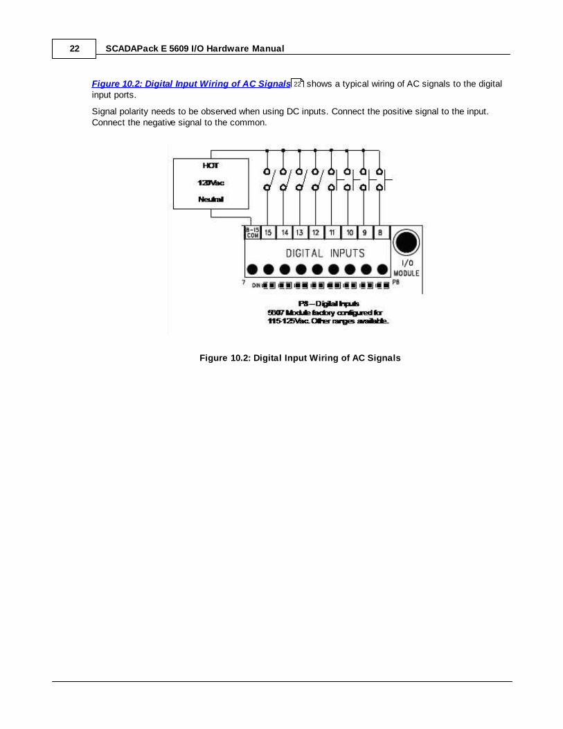
Figure 10.2: Digital Input Wiring of AC Signals shows a typical wiring of AC signals to the digitalinput ports.
Signal polarity needs to be observed when using DC inputs. Connect the positive signal to the input.Connect the negative signal to the common.
Figure 10.2: Digital Input Wiring of AC Signals
22
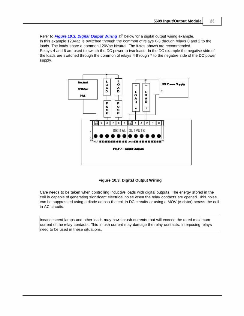
5609 Input/Output Module 23
Refer to Figure 10.3: Digital Output Wiring below for a digital output wiring example. In this example 120Vac is switched through the common of relays 0-3 through relays 0 and 2 to theloads. The loads share a common 120Vac Neutral. The fuses shown are recommended. Relays 4 and 6 are used to switch the DC power to two loads. In the DC example the negative side ofthe loads are switched through the common of relays 4 through 7 to the negative side of the DC powersupply.
Figure 10.3: Digital Output Wiring
Care needs to be taken when controlling inductive loads with digital outputs. The energy stored in thecoil is capable of generating significant electrical noise when the relay contacts are opened. This noisecan be suppressed using a diode across the coil in DC circuits or using a MOV (varistor) across the coilin AC circuits.
Incandescent lamps and other loads may have inrush currents that will exceed the rated maximumcurrent of the relay contacts. This inrush current may damage the relay contacts. Interposing relaysneed to be used in these situations.
23

SCADAPack E 5609 I/O Hardware Manual24
9 Operation and Maintenance
LED IndicatorsThere are 56 LED’s on the 5609 I/O Module. LED’s can be disabled by the controller board to conservepower. Refer to the manual of your controller board for details on disabling the LEDs.
The table below describes the LED’s.
Table 11.1: LED Indicators
LED Function
DOUTs On when the corresponding output is on.
DINs On when the corresponding input is on.
AINs On when analog input is configured for current.
Off when analog input is configured for voltage.
Long flashes when the applied current is out ofrange.
Short flashes when the applied voltage is out ofrange.*
* Under-range is not indicated on analog input channel LEDs on the 5609 I/O module when configured in1-5V input range.
MaintenanceThis module requires no routine maintenance. If the module is not functioning correctly, contactSchneider Electric Technical Support for more information and instructions for returning the module forrepair.

5609 Input/Output Module 25
9.1 Troubleshooting
CalibrationThe 5609 module is calibrated at the factory. It does not require periodic calibration. Calibration may benecessary if the module has been repaired as a result of damage. Calibration is done electronically atthe factory. There are no user calibration procedures.
Analog Inputs
Digital Inputs & Outputs
26
27
SCADAPack E 5609 I/O Hardware Manual26
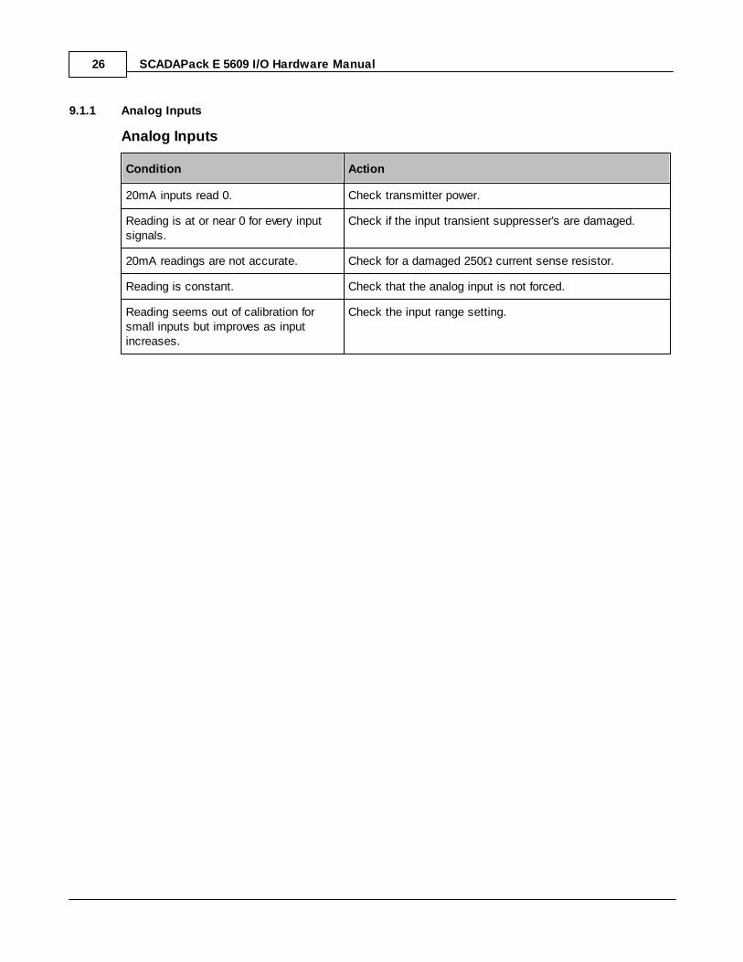
9.1.1 Analog Inputs
Analog Inputs
Condition Action
20mA inputs read 0. Check transmitter power.
Reading is at or near 0 for every inputsignals.
Check if the input transient suppresser's are damaged.
20mA readings are not accurate. Check for a damaged 250 current sense resistor.
Reading is constant. Check that the analog input is not forced.
Reading seems out of calibration forsmall inputs but improves as inputincreases.
Check the input range setting.

5609 Input/Output Module 27
9.1.2 Digital Inputs & Outputs
Digital Inputs
Condition Action
Input LED does not come on when inputsignal is applied.
Check the input signal at the termination block. It should beat least 50% of the digital input range.
If this is a DC input, check the polarity of the signal.
Input is on when no signal is applied.The LED is off.
Check that the digital inputs are not forced on.
Input is off when a signal is applied. TheLED is on.
Check that the digital inputs are not forced off.
Digital Outputs
Condition Action
Output LED does not come on whenoutput is turned on.
Check the LED POWER from the SCADAPack controller.
Output LED comes on but the outputdoes not close.
Check if the relay is stuck. If so, return the board for repair.
Output LED comes on and output isclosed, but the field device is notactivated.
Check the field wiring.
Check the external device.
Output LED and relay are on when theyshould be off.
Check that the output is not forced on.
Output LED and relay are off when theyshould be on.
Check that the output is not forced off.

SCADAPack E 5609 I/O Hardware Manual28
10 Specifications
Disclaimer: Schneider Electric reserves the right to change product specifications without notice. Formore information visit http://www.schneider-electric.com.
General & Power Supply
Analog Inputs
Digital Inputs
Relay Digital Outputs
29
30
31
32

5609 Input/Output Module 29
10.1 General & Power Supply
General
I/O Terminations 12 to 22 AWG
15A contacts
Screw termination - 6 lb.-in. (0.68 Nm) torque
Dimensions 5.65 inch (144mm) wide
6.50 inch (165mm) high
1.80 inch (72mm) deep
Packaging corrosion resistant zinc plated steel with black enamel paint
Environment 5% RH to 95% RH, non-condensing
–25ºC to 70ºC (–13ºF to 158ºF) operation
–40ºC to 85ºC (–40ºF to 185ºF) storage
Addressing 8 modules. DIP switch selectable.
Power Supply
5V power requirements
(Dry Contact Relay Version)
Digital Output Relays Continuous - 195mA
LEDs - 107mA
Quiescent - 23mA
Total - up to 325mA
5V power requirements
(Solid State Relay Version)
Digital Output Relays Continuous - 100mA
LEDs - 110mA
Quiescent - 23mA
Total - up to 233mA
11-30Vdc powerrequirements
9-30Vdc operation possible
UL508 rated 13.75 to 28Vdc.
11-30Vdc - Connector Removable. 5 positions.
11-30Vdc - Isolation Isolation from logic supply and chassis
SCADAPack E 5609 I/O Hardware Manual30
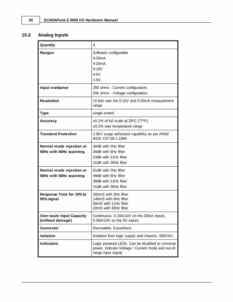
10.2 Analog Inputs
Quantity 4
Ranges Software configurable
0-20mA
4-20mA
0-10V
0-5V
1-5V
Input resistance 250 ohms - Current configuration.
20k ohms - Voltage configuration.
Resolution 15 bits over the 0-10V and 0-20mA measurementrange
Type single ended
Accuracy ±0.1% of full scale at 25ºC (77ºF)
±0.2% over temperature range
Transient Protection 2.5kV surge withstand capability as per ANSI/IEEE C37.90.1-1989
Normal mode rejection at
60Hz with 60Hz scanning
30dB with 3Hz filter
28dB with 6Hz filter
23dB with 11Hz filter
21dB with 30Hz filter
Normal mode rejection at
50Hz with 50Hz scanning
51dB with 3Hz filter
49dB with 6Hz filter
38dB with 11Hz filter
21dB with 30Hz filter
Response Time for 10% to90% signal
300mS with 3Hz filter140mS with 6Hz filter60mS with 11Hz filter20mS with 30Hz filter
Over-scale Input Capacity(without damage)
Continuous: 0.10A/14V on the 20mA inputs.0.05A/14V on the 5V inputs.
Connector Removable. 9 positions.
Isolation Isolation from logic supply and chassis. 500VAC
Indicators Logic powered LEDs. Can be disabled to conservepower. Indicate Voltage / Current mode and out-of-range input signal

5609 Input/Output Module 31
10.3 Digital Inputs
Quantity 12
Ranges Factory configurable
12/24V
48V
115/125V
240V
Over-voltage Tolerance 150% sustained over-voltage without damage
Input Current 0.67 mA typical at 24V on the 12/24V range0.37 mA typical at 48V on the 48V range
0.35 mA typical at 120V on the 115/125V range
0.35 mA typical at 240V on the 240V range
Input Logic-HI Level OFF to ON transition threshold is typically 6.5Von 12/24V range
OFF to ON transition threshold is typically 50% offull scale range on other ranges.
AC Input Voltage
12V/24V
48V
115/125V
240V
Off – To – On
7.5Vrms+/- 2Vrms
25Vrms +/- 5Vrms
65Vrms+/- 5Vrms
135Vrms+/-10Vrms
On – To – Off
6.0Vrms+/ - 2Vrms
20Vrms +/- 5Vrms
55Vrms+/- 5Vrms
115Vrms+/-10Vrms
DC Input Voltage
12V/24V
48V
115/125V
240V
Off – To – On
6.5Vdc+/- 0.5Vdc
22Vdc+/-5Vdc
65Vdc+/-5Vdc
125Vdc+/-10Vdc
On – To – Off
6.5Vdc+/- 0.5Vdc
22Vdc+/-5Vdc
65Vdc+/-5Vdc
125Vdc+/-10Vdc
AC Response Time
@50 Hz
@60 Hz
Off – To – On
5 – 22ms
5-– 22ms
On – To – Off
6 – 18ms
6 – 18ms
DC Response Time
@50 Hz
@60 Hz
Off – To – On
15 – 19ms
13.5 – 18ms
On – To – Off
25 – 29ms
23 - 28ms
Connectors 2 removable. 9 positions.
Isolation Isolation is in 2 groups of 8 and 4 respectively.Isolation from logic supply and chassis:250Vac/1000Vdc.
Indicators Logic powered LEDs. Can be disabled to conservepower.

SCADAPack E 5609 I/O Hardware Manual32
10.4 Digital Outputs
Quantity 6
Connectors 2 removable. 6 positions.
Type Form A Contacts (Normally open)
5 contacts share one common
Indicators Logic powered LEDs. Can be disabled to conservepower.
Voltages Maximum permitted voltage in Canada or NorthAmerica is 240Vac.
Maximum permitted voltage outside of Canada orNorth America is 30Vac/42.4Vpk/60Vdc.
Inductive Loads Inductive loads need to be suitably protected toprotect the relay contacts. See manual forrecommended inductive load protection circuits.
Isolation Chassis to contact: 1500Vac (1 min.)
Logic to contact: 1500Vac (1 min.)
Isolation is in 2 groups of 5
Output group to output group: 1500Vac (1 min.)
Operate Time 25ms maximum, 20ms typical
Release Time 30ms maximum, 25ms typical
Dry Contact Relays
Contact rating 3A, 30Vdc or 240Vac (Resistive)
1000Vac between open contacts
12A maximum per common
Switching Capacity 5A, 30Vdc (150W Resistive)5A X 250Vac (1250VA Resistive)
Service Life 2 X 10⁷ mechanical
1 X 10⁵ at contact rating
Bounce Time 1ms typical
11 Approvals and Certifications
SafetyUL (cULus) listed: UL508 (Industrial Control Equipment), CSAC22.2 No.142-M1987 (Process Control Equipment)
Digital Emissions FCC47 Part 15, Subpart B, Class A Verification
EN61000-6-4: 2007 Electromagnetic Compatibility GenericEmission Standard Part2: Industrial Environment

5609 Input/Output Module 33
C-Tick compliance. Registration number N15744
Immunity EN61000-6-2: 2005 Electromagnetic Compatibility GenericStandards Immunity for Industrial Environments
CE MarkDeclaration
This product conforms to the above Emissions and ImmunityStandards and therefore conforms with the requirements ofCouncil Directive 2004/108/EEC (as amended) relating toelectromagnetic compatibility and is eligible to bear the CE mark
The Low Voltage Directive is not applicable to this product.

SCADAPack E 5609 I/O Hardware Manual34