5606 i/o module hardware manual (337e only) · • scadapack 357e - a 5209 controller board with an...
TRANSCRIPT

5606 I/O Module Hardware Manual (337E Only)
SCADAPack E
Version:
Date:
8.14.3
August 2017

2
Table of Contents
.....................................................................................................................................................51 Legal Information
.....................................................................................................................................................62 Technical Support
.....................................................................................................................................................73 Safety Information
.....................................................................................................................................................104 Overview
.....................................................................................................................................................115 Installation
.....................................................................................................................................................136 Power Supply Overview and Requirements
............................................................................................................................................136.1 Recommended AC Power Supply Configuration
............................................................................................................................................136.2 Recommended 24V Power Supply Configuration
............................................................................................................................................136.3 Recommended Battery Configuration
............................................................................................................................................136.4 Recommended 5103 Power Supply Configuration
.....................................................................................................................................................187 DIP Switch Settings
.....................................................................................................................................................198 Analog Inputs
............................................................................................................................................198.1 Current or Voltage Mode & Range and Resolution
............................................................................................................................................198.2 Wiring
.....................................................................................................................................................269 Analog Outputs
............................................................................................................................................269.1 Current & Voltage Outputs
............................................................................................................................................269.2 Range and Resolution
.....................................................................................................................................................2910 Digital I/O Overview
............................................................................................................................................2910.1 Digital Inputs & Outputs
............................................................................................................................................2910.2 Wiring Examples
.....................................................................................................................................................3511 Operation and Maintenance
............................................................................................................................................3511.1 Troubleshooting
..........................................................................................................................3511.1.1 Analog Inputs & Outputs
..........................................................................................................................3511.1.2 Digital Inputs & Outputs
.....................................................................................................................................................3812 Specifications
............................................................................................................................................3812.1 General & Power Supply
............................................................................................................................................3812.2 Analog Inputs

3
............................................................................................................................................3812.3 Analog Outputs
............................................................................................................................................3812.4 Digital Inputs
............................................................................................................................................3812.5 Digital Outputs
.....................................................................................................................................................4513 Approvals and Certifications

8.14.3
5606 I/O Module Hardware Manual (337E Only)
4

8.14.3
5606 I/O Module Hardware Manual (337E Only) Legal Information
5
1 Legal Information
The information provided in this documentation contains general descriptions and/or technicalcharacteristics of the performance of the products contained herein. This documentation is not intendedas a substitute for and is not to be used for determining suitability or reliability of these products forspecific user applications. It is the duty of any such user or integrator to perform the appropriate andcomplete risk analysis, evaluation and testing of the products with respect to the relevant specificapplication or use thereof. Neither Schneider Electric nor any of its affiliates or subsidiaries shall beresponsible or liable for misuse of the information contained herein. If you have any suggestions forimprovements or amendments or have found errors in this publication, please notify us.
No part of this document may be reproduced in any form or by any means, electronic or mechanical,including photocopying, without express written permission of Schneider Electric.
All pertinent state, regional, and local safety regulations must be observed when installing and using thisproduct. For reasons of safety and to help ensure compliance with documented system data, only themanufacturer should perform repairs to components.
Trademarks
Schneider Electric, ClearSCADA, SCADAPack, Trio, Modbus, and StruxureWare are trademarks andthe property of Schneider Electric SE, its subsidiaries and affiliated companies. All other trademarks arethe property of their respective owners.
Address
Schneider Electric
415 Legget Drive, Suite 101, Kanata, Ontario K2K 3R1 CanadaDirect Worldwide: +1 (613) 591-1943Fax: +1 (613) 591-1022Toll Free within North America: 1 (888) 267-2232www.schneider-electric.com
© 2014 - 2017 Schneider Electric Canada Inc.All rights reserved.

8.14.3
5606 I/O Module Hardware Manual (337E Only)Technical Support
6
2 Technical Support
Questions and requests related to any part of this documentation can be directed to one of the followingsupport centers.
Technical Support: Americas, Europe, Middle East, Asia
Available Monday to Friday 8:00am – 6:30pm Eastern Time
Toll free within North America 1-888-226-6876
Direct Worldwide +1-613-591-1943
Email [email protected]
Technical Support: Australia
Inside Australia 1300 369 233
Email [email protected]

8.14.3
5606 I/O Module Hardware Manual (337E Only) Safety Information
7
3 Safety Information
Important Information
Read these instructions carefully and look at the equipment to become familiar with the devicebefore trying to install, operate, service, or maintain it. The following special messages mayappear throughout this documentation or on the equipment to warn of potential hazards or tocall attention to information that clarifies or simplifies a procedure.
The addition of this symbol to a Danger or Warning safety label indicatesthat an electrical hazard exists, which will result in personal injury if theinstructions are not followed.
This is the safety alert symbol. It is used to alert you to potential personalinjury hazards. Obey all safety messages that follow this symbol to avoidpossible injury or death.
DANGER
DANGER indicates a hazardous situation which, if not avoided, will result in deathor serious injury.
WARNING
WARNING indicates a hazardous situation which, if not avoided, can result indeath or serious injury.
CAUTION
CAUTION indicates a potentially hazardous situation which, if not avoided, canresult in minor or moderate injury.
NOTICE
NOTICE is used to address practices not related to physical injury.

8.14.3
5606 I/O Module Hardware Manual (337E Only)Safety Information
8
Please Note
Electrical equipment should be installed, operated, serviced, and maintained only by qualified personnel.No responsibility is assumed by Schneider Electric for any consequences arising out of the use of thismaterial.
A qualified person is one who has skills and knowledge related to the construction, installation, andoperation of electrical equipment and has received safety training to recognize and avoid the hazardsinvolved.
Before You Begin
Do not use this product on machinery lacking effective point-of-operation guarding. Lack of effective point-of-operation guarding on a machine can result in serious injury to the operator of that machine.
WARNINGEQUIPMENT OPERATION HAZARD
· Verify that all installation and set up procedures have been completed.
· Before operational tests are performed, remove all blocks or other temporaryholding means used for shipment from all component devices.
· Remove tools, meters, and debris from equipment.
Failure to follow these instructions can result in death or serious injury.
Follow all start-up tests recommended in the equipment documentation. Store all equipmentdocumentation for future reference.
Test all software in both simulated and real environments.
Verify that the completed system is free from all short circuits and grounds, except those groundsinstalled according to local regulations (according to the National Electrical Code in the U.S.A, forinstance). If high-potential voltage testing is necessary, follow recommendations in equipmentdocumentation to help prevent accidental equipment damage.
Operation and Adjustments
The following precautions are from the NEMA Standards Publication ICS 7.1-1995 (English versionprevails):
· Regardless of the care exercised in the design and manufacture of equipment or in the selection andratings of components, there are hazards that can be encountered if such equipment is improperlyoperated.
· It is sometimes possible to misadjust the equipment and thus produce unsatisfactory or unsafeoperation. Always use the manufacturer’s instructions as a guide for functional adjustments. Personnelwho have access to these adjustments should be familiar with the equipment manufacturer’sinstructions and the machinery used with the electrical equipment.
· Only those operational adjustments actually required by the operator should be accessible to theoperator. Access to other controls should be restricted to help prevent unauthorized changes inoperating characteristics.

8.14.3
5606 I/O Module Hardware Manual (337E Only) Safety Information
9
Acceptable Use
SCADAPack E remote Programmable Automation Controllers (rPACs), Remote Terminal Units (RTUs)and input/output (I/O) modules are intended for use in monitoring and controlling non-critical equipmentonly. They are not intended for safety-critical applications.
WARNINGUNACCEPTABLE USE
Do not use SCADAPack E rPACs, RTUs, or I/O modules as an integral part of asafety system. These devices are not safety products.
Failure to follow this instruction can result in death or serious injury.
CAUTION
EQUIPMENT OPERATION HAZARD
When devices are used for applications with technical safety requirements, therelevant instructions must be followed.
Use only Schneider Electric software or approved software with Schneider Electrichardware products.
Failure to follow these instructions can result in minor or moderate injury.

8.14.3
5606 I/O Module Hardware Manual (337E Only)Overview
10
4 Overview
The 5606 I/O module, also available as a standalone unit, can be integrated with a SCADAPack Econtroller. The following controllers support the 5606 I/O module:
· SCADAPack 357E - A 5209 controller board with an integrated 5606 I/O Module
· SCADAPack 300E - A 5606 I/O module connected to the 5000 Series I/O Bus
· SCADAPack ES - A 5606 I/O module connected to the 5000 Series I/O Bus
The 5606 I/O module, also available as a standalone unit, increases the I/O capability of a SCADAPackE Smart RTU by providing 8 analog inputs, 32 digital inputs and 16 relay digital outputs. Optionally, twoanalog outputs can be specified at time of purchase.
A maximum of eight (8) 5606 modules can be addressed on a 5000 Series I/O bus.
The analog inputs are used with devices such as pressure, level, flow, and temperature transmitters;instrumentation such as pH and conductivity sensors; and other high-level analog signal sources. The5606 input module measures current or voltage inputs in the ranges 0 to 20mA, 4-20mA, 0 to 5 V or 1 to5 V. Each input is individually configured for input type and range. The 5606 module uses a 16-bit analogto digital (A/D) converter.
The 5606 I/O and outputs are transient protected and optically isolated from the main logic power. Theinputs are single ended. They share a common return.
The digital inputs are optically isolated from the logic power. To simplify field wiring, the inputs aregrouped with eight inputs sharing a single common return. These groups of eight inputs are isolated fromeach other. Light emitting diodes show the status of each of the inputs. The digital inputs are available intwo standard voltage ranges, for both AC and DC applications.
The 5606 adds sixteen, dry contact, Form A (normally open) mechanical relay outputs to a 5000 Seriesinput/output system. The relay outputs can be used to control panel lamps, relays, motor starters,solenoid valves, and other on/off devices. The relay outputs are well suited to applications that cannottolerate any off-state leakage current, that require high load currents, or that involve non-standardvoltages or current ranges.
This manual covers the powering, wiring and configuration of a 5606 I/O module only. It is meant tobe used with the hardware manual of the respective controller board to which the I/O module isattached.

8.14.3
5606 I/O Module Hardware Manual (337E Only) Installation
11
5 Installation
The installation of the 5606 module requires mounting the module on the 7.5mm by 35mm DIN rail andconnecting the module to the system I/O Bus. Refer to the Schneider Electric System ConfigurationGuide for complete information on system layout, I/O Bus cable routing and module installation.
Field Wiring ConnectorsThe 5606 I/O modules use screw termination style connectors for termination of field wiring. Theseconnectors accommodate solid or stranded wires from 12 to 22 AWG.
Remove power before servicing unit.
The 5606 I/O Module has eight termination connectors for the connection of field wiring. Refer to Figure5.1: 5606 I/O Module Layout for wiring connector locations.
· Primary power input connections and optional analog output connections are wired to a 5 poleconnector labeled P3. Refer to Section Power Supply Overview and Requirements for moreinformation on these connections. Loop current will only flow in analog inputs that have beenconfigured for 20mA and when power is applied to P3.
· The eight analog inputs are wired to a 9 pole connector labeled P4. Refer to Section Analog Inputs for more information on wiring analog input signals.
· The digital outputs are wired to two 10 pole connectors labeled P5 and P6. Refer to the Section Digital Inputs & Outputs (Digital Outputs) for details on wiring the digital outputs.
· The digital inputs are wired to four 9 pole connectors labeled P7, P8, P9 and P10. Refer to Section Digital Inputs & Outputs (Digital Inputs) for details on wiring the digital inputs.
Digital Inputs 24-31Connector (P10)
Digital Inputs 16-23Connector (P9)
Digital Inputs 8-15Connector (P8)
Digital Inputs 0-7Connector (P7)
Power – Analog OutConnector (P3)
Analog InputsConnector (P4)
Digital Outputs 0-7Connector (P5)
Digital Outputs 8-15Connector (P6)
Address
Figure 5.1: 5606 I/O Module Layout
11
13
19
30
30

8.14.3
5606 I/O Module Hardware Manual (337E Only)Installation
12
ATEX and IECEx applications only
This equipment is to be installed in an enclosure certified for use, providing a degree of protection of IP54or better. The free internal volume of the enclosure must be dimensioned in order to keep the temperaturerating. A T4 rating is acceptable. For products using Solid State Relays (5606 SSR) a T4 rating isacceptable for maximum loads of 2A. When 3A loads are connected to the Solid State Relays, themaximum ambient rating is lowered to 50°C in order to maintain the T4 rating.

8.14.3
5606 I/O Module Hardware Manual (337E Only) Power Supply Overview and Requirements
13
6 Power Supply Overview and Requirements
The 5606 I/O module requires a nominally 12V or 24V DC power supply applied to the terminals labeled11-30V on connector P3 to power the analog input and optional analog output circuitry.
The current requirement of the analog portion (input and optional output circuitry) on the 5606 I/O boardcan vary from a minimum of 12mA for basic operation of the analog circuitry plus an additional 40mA forthe optional analog outputs.
In addition, the system controller or power supply provides 5V through the I/O Bus cable. Refer to theSpecifications section of the controller manual for the power capabilities of the controller. A samplepower calculation for integrated SCADAPack controller utilizing this I/O board can be found in the manualof the corresponding controller board.
Power for the I/O board can be provided in several ways:
· With a 16Vac source supplying power to the controller board, 24V is available on the DC PWRterminals on connector P5 of the controller board which can be used to power the lower I/O model. See the Section Recommended AC Power Supply Configuration below for details.
· A 24Vdc source connected to the DC PWR terminals on the controller board and on the 5606 I/Omodule in a parallel configuration. See Section Recommended 24V Power Supply Configuration
for an example on this wiring configuration.
· With a 12Vdc source connected to the DC PWR terminals on the controller board and on the 5606 I/O module in a parallel configuration. See Section Recommended Battery Configuration for anexample of using a DC power source coming from a 12Vdc battery.
· A 5103 UPS Power Supply supplies 5Vdc to the controller board through the IMC cable and supplies24Vdc to the 5606 I/O module through the 24Vdc output. See Section Recommended 5103 PowerSupply Configuration for an example of using the 5103 UPS Power Supply.
Power can be applied to either the AC/DC power input OR the DC power input. Damage to the powersupply may result if power is applied to both inputs.
System GroundingIt is desirable to ground the system by connecting the system power supply common, to the chassis orpanel ground. On the 5606 I/O module, the “-“ terminal of the 11-30V supply (DC PWR “-“) along withterminals labeled COM are isolated from the chassis.
14
15
16
17

8.14.3
5606 I/O Module Hardware Manual (337E Only)Power Supply Overview and Requirements
14
6.1 Recommended AC Power Supply Configuration
This configuration uses a single Class 2 16Vac transformer to power the controller board and the 5606 I/O Module. 24V is available on the controller module connector P3. This is used to power the analogcircuitry on the 5606 I/O module.
Notes on this configuration:
· Only a limited amount of power is available from the controller. This configuration is notrecommended when a large amount of current is required at 24V.
· The Controller Board DC Power terminal needs to be connected to the same power supply as the5606 I/O Module DC Power terminals.
120 Vrms
16 Vrms
Class 2 Transformer
AC/DC PWR IN
DC PWR + –
1 2 3 4 5 6 P3
Controller Board
P3
5606 I/O Module
DC PWR + –
1 2 3 4 5
AOUT 0 1 COM
Figure 6.1: Recommended AC Power Supply Configuration

8.14.3
5606 I/O Module Hardware Manual (337E Only) Power Supply Overview and Requirements
15
6.2 Recommended 24V Power Supply Configuration
This configuration uses a 24V power supply to power the controller board and the 5606 I/O module. This24V is used to power the analog circuitry for the analog on the 5606 I/O module.
Notes on this configuration:
· This configuration is recommended when a large amount of current is required at 24V. Refer toSection Specifications .
· The Controller Board DC Power terminal needs to be connected to the same power supply as the5606 I/O Module DC Power terminals.
+ 24Vdc Power
Supply –
P3
5606 I/O Module
DC PWR + –
1 2 3 4 5
AOUT 0 1 COM
AC/DC PWR IN
DC PWR + –
1 2 3 4 5 6 P3
Controller Board
Figure 6.2: Recommended DC Power Supply Configuration
38

8.14.3
5606 I/O Module Hardware Manual (337E Only)Power Supply Overview and Requirements
16
6.3 Recommended Battery Configuration
This configuration uses a 12V battery to power the controller board and the 5606 I/O Module. This 12V isused to power the analog circuitry for the analog inputs and analog outputs on the 5606 I/O Module.
Notes on this configuration:
· This configuration is recommended when a large amount of current is required at 12V. Refer toSection Specifications for power requirements from a 12V battery.
· The Controller Board DC Power terminal needs to be connected to the same power supply as the5606 I/O Module DC Power terminals.
12V battery
P3
5606 I/O Module
DC PWR + –
1 2 3 4 5
AOUT 0 1 COM
AC/DC PWR IN
DC PWR + –
1 2 3 4 5 6 P3
Controller Board
Figure 6.3: Recommended Battery Configuration
38

8.14.3
5606 I/O Module Hardware Manual (337E Only) Power Supply Overview and Requirements
17
6.4 Recommended 5103 Power Supply Configuration
When additional power is required by the system, 5000 Series 5103 power supplies can be used incombination with the SCADAPack controllers. Refer to the System Configuration Guide for moreinformation.
The 5103 power supplies can be connected anywhere downstream (to the right) of the controller. Theywill supply power to the modules downstream of them.
The Sleep Mode feature of the controller applies only to those modules powered by the controller.
The 5103 power supply may also be connected upstream (to the left) of any SCADAPack Controller, butonly if the following conditions are observed:
· No power is applied to the power inputs of the controller board.
· A jumper is installed at position J5. See the hardware manual of your respective controller board forthe location and use of this jumper.
· The sleep mode feature is not used.
This configuration uses a 5103 Power Supply module to power a SCADAPack controller. The 24VDCoutput from the 5103 powers the 5606 I/O module. The 5103 power supply provides a 5V output to powerthe 5606 I/O module, the controller board and 5000 Series modules through the IMC cables.
No connection is made to the AC/DC PWR IN or DC PWR terminals on the controller board.
AC/DC PWR IN
DC PWR + –
1 2 3 4 5 6 P5
Controller Board
1 2 3 4 5 9 10 P3
J5 5103 Power Supply
120 Vrm
s
24 Vrms
Class 2 Transformer
AC/DC
+ -BATT
+ - 24V
Optional 12 Volt Gel Cel Battery
P3
5606 I/O Module
DC PWR + –
1 2 3 4
AOUT 0 1 COM
5
Figure 6.4: Recommended 5103 Power Supply Configuration

8.14.3
5606 I/O Module Hardware Manual (337E Only)DIP Switch Settings
18
7 DIP Switch Settings
Address Selection5000 Series I/O module types may be combined in any manner to the maximum supported by thecontroller used.
Each type of I/O module, connected to the I/O bus, needs to have a unique I/O module address. Differenttypes of I/O modules may have the same module address.
The address range supported by the controller module may restrict the I/O module address range. Referto the controller manual for the maximum address supported.
5606 AddressingThree address switches on the 5606 labeled 4, 2, and 1 set the address. A 5606 I/O module that isinstalled in a SCADAPack is generally set to address 0. Address 0 can be used if there is no 5606installed in a SCADAPack. A second 5606 is generally set to address 1.
The 5606 and 5607 modules share the same address numbering, and therefore 5606 and 5607 moduleson the I/O bus need to have unique address numbers.
To set the address:
1. Open the four switches by sliding the actuators to the “OFF” position.
2. Close the switches that total to the desired address by sliding the actuators to “ON”. Switch settingsfor each of the 8 module addresses are shown in the figure below.
ModuleAddress
0
21
4
How to Set Address Switches· Determine the module address.
· Slide actuators (side shown in gray)
Slide to this side toignore switch value.
ModuleAddress
1
21
4
ModuleAddress
2
21
4
ModuleAddress
3
21
4
ModuleAddress
4
21
4
ModuleAddress
5
21
4
ModuleAddress
6
21
4
ModuleAddress
7
21
4
Slide to this side toadd switch value.
Figure 7.1: 5606 Address Switch Settings

8.14.3
5606 I/O Module Hardware Manual (337E Only) Analog Inputs
19
8 Analog Inputs
The 5606 I/O module enhances the capacity of a SCADAPack controller by providing an additional eightsingle ended analog inputs on connector P4 that can be configured for current or voltage mode. Refer to Figure 5.1: 5606 I/O Module Layout for the location of this connector.
Analog inputs can be configured for current or voltage mode via software. Please refer to the Section Current or Voltage Mode & Range and Resolution (Current or Voltage Mode) below on how tochoose input modes.
· In voltage mode, these analog inputs are single ended with a measurement range of 0-5V or 0-10V.The range is selected via software.
· In current mode, a 250W current sense resistor appears across each analog input channel. Measurement range in current mode is 0-20mA or 4-20mA selectable via software. The 250Wresistor produces a voltage drop (input reading) of 5V for a 20mA of current flow.
The analog inputs use a 16-bit successive approximation digital to analog (A/D) converter.
· Use SCADAPack E Configurator to assign RTU database points to the I/O card channels
· For ISaGRAF applications use I/O board connections to the RTU point database (rtuxxxx boards) orComplex Equipment types (sp357e) to read the eight analog inputs.
Please refer to the ISaGRAF software and SCADAPack E Configurator manuals on how to assign RTUpoints to use ISaGRAF I/O Boards and Complex Equipment types.
Configuration for points attached to the 5606 Analog Input channels uses the SCADAPack ERAW_MIN / RAW_MAX and ENG_MIN / ENG_MAX parameters for integer and engineering scaling,respectively. These scaling ranges apply to the analog input signal range selected by SCADAPack EConfigurator for each analog input point channel on the 5606 I/O module.
11
20
8.14.3
5606 I/O Module Hardware Manual (337E Only)Analog Inputs
20
8.1 Current or Voltage Mode & Range and Resolution
Current or Voltage ModeThe analog inputs on the 5606 module can be configured for either voltage or current mode viaSCADAPack E Configurator.
In current mode a 250W resistor appears across the analog input channel. In voltage mode, inputchannels are high impedance.
Range and ResolutionThe 5606 analog inputs (Channels 0-7) have a 16-bit, unipolar, analog to digital (A/D) converter thatmeasures input voltages from 0-5V or 0-10V. The analog inputs are factory calibrated to scale the dataand represent it with a 16 bit signed number.
When assigning RTU database points to the 5606 module channels using SCADAPack E Configurator,the user configures the Input Type signal range for each analog input channel.
The following Input Type ranges can be configured for each 5606 analog input channel:
· 0 to 5V
· 1 to 5V
· 0 to 10V
· 0 to 20mA
· 4 to 20mA
The Input Type range selected is scaled to the Raw Min. to Raw Max. range configured for theindividual analog input point when point integer values are used. The Eng. Min. to Eng. Max. range forthe point is used to scale the analog input Engineering Floating Point database value.
For example, if a SCADAPack 357E analog input or 5606 Module point's attributes are RAW_MIN = 0,RAW_MAX = 10000 and the input channel is selected for 4-20mA: a 20mA input is 100% of the selectedinput signal range and corresponds to 10000 counts. a 4mA input is 0% of the selected input signalrange and corresponds to 0 counts.
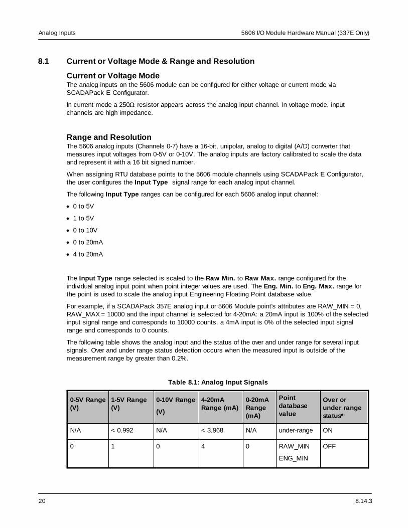
The following table shows the analog input and the status of the over and under range for several inputsignals. Over and under range status detection occurs when the measured input is outside of themeasurement range by greater than 0.2%.
Table 8.1: Analog Input Signals
0-5V Range(V)
1-5V Range(V)
0-10V Range
(V)
4-20mARange (mA)
0-20mARange(mA)
Pointdatabasevalue
Over orunder rangestatus*
N/A < 0.992 N/A < 3.968 N/A under-range ON
0 1 0 4 0 RAW_MIN
ENG_MIN
OFF

8.14.3
5606 I/O Module Hardware Manual (337E Only) Analog Inputs
21
0-5V Range(V)
1-5V Range(V)
0-10V Range
(V)
4-20mARange (mA)
0-20mARange(mA)
Pointdatabasevalue
Over orunder rangestatus*
1.25 2 2.5 8 5 25% of scale OFF
2.5 3 5.0 12 10 50% of scale OFF
3.75 4 7.5 16 15 75% of scale OFF
5 5 10 20 20 RAW_MAX
ENG_MAX
OFF
5.0024 5.0024 10.0048 20.032 20.01 over-range ON
* Under-range and Over-range point status may also be asserted by SCADAPack E Analog Input Pointconfiguration parameters. For more information see the SCADAPack E 5000 Series I/O ExpansionReference manual and SCADAPack E Data Processing Technical Reference manual.
8.14.3
5606 I/O Module Hardware Manual (337E Only)Analog Inputs
22
8.2 Wiring
The analog inputs support loop powered and self powered transmitters. Loop powered transmitters aretwo terminal devices that are connected between a power supply and the analog input. The loop currentfrom the power supply travels through the transmitter, and to ground through a 250W resistor built intothe 20mA input circuit. Self-powered transmitters have three terminals: Power In, Signal Out and,Common. Self-powered transmitters can have a current or voltage output. Signal out connects to theAnalog Input Channel; Common connects to COM; and, Power In connects to a power supply.
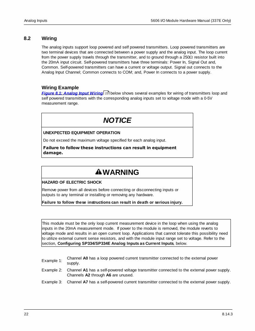
Wiring ExampleFigure 8.1: Analog Input Wiring below shows several examples for wiring of transmitters loop andself powered transmitters with the corresponding analog inputs set to voltage mode with a 0-5Vmeasurement range.
NOTICE
UNEXPECTED EQUIPMENT OPERATION
Do not exceed the maximum voltage specified for each analog input.
Failure to follow these instructions can result in equipmentdamage.
WARNINGHAZARD OF ELECTRIC SHOCK
Remove power from all devices before connecting or disconnecting inputs oroutputs to any terminal or installing or removing any hardware.
Failure to follow these instructions can result in death or serious injury.
This module must be the only loop current measurement device in the loop when using the analoginputs in the 20mA measurement mode. If power to the module is removed, the module reverts tovoltage mode and results in an open current loop. Applications that cannot tolerate this possibility needto utilize external current sense resistors, and with the module input range set to voltage. Refer to thesection, Configuring SP334/SP334E Analog Inputs as Current Inputs, below.
Example 1:Channel A0 has a loop powered current transmitter connected to the external powersupply.
Example 2: Channel A1 has a self-powered voltage transmitter connected to the external power supply.Channels A2 through A6 are unused.
Example 3: Channel A7 has a self-powered current transmitter connected to the external power supply.
23

8.14.3
5606 I/O Module Hardware Manual (337E Only) Analog Inputs
23
+ External 12 or 24Vdc Power
Supply _
8
+
_
+Vdc – 0 1 COM
7 6 5 4 3 2 1
0 1 2 3 4 5 6 7 COM
P4 - Analog Inputs
PWR
Voltage O/P
COM
PWR
Current O/P
COM
9 5 4 3 2 1
P3 – Power and Analog Outputs
A0 A1 A2 A3 A4 A5 A6 A7COM
Figure 8.1: Analog Input Wiring
Configuring SP334/SP334E Analog inputs as Current Inputs
The analog inputs for the SCADAPack 334/SP334E modules are configured in Current Input mode andhave these possible operating conditions::
· The SP334/SP334E is not the only transducer in a particular current loop;
· The SP334/SP334E is powered down, or reset.
If you power down or reset the SP334/334E module in a multiple device loop, the analog inputs emulatevoltage inputs that present a high impedance to the current loop, and effectively break the current loop ofthe system.
Preventing Interruption of the Current Loop
Prevent the interruption of the current loop in the module by configuring the analog inputs as voltageInputs, and add an external 253 resistor to the current loop at the terminal strip as shown in the figurebelow.

8.14.3
5606 I/O Module Hardware Manual (337E Only)Analog Inputs
24
This wiring method is preferred if you need to swap the SCADAPack SP334/334E Module; you canremove the module without affecting the current loop; the loop is NOT interrupted if the device is removed.
The circuit configurations for the external 253 ohm resistor, or a signal isolator, are shown in the figurebelow:

8.14.3
5606 I/O Module Hardware Manual (337E Only) Analog Inputs
25
1. The external resistor shown here must be 253 Ohms in consideration of the 20K ohm internalresistance of the SCADAPack 334/334E Voltage Input circuit as shown in Circuit 1.
2. The SP MUST be the last device in the current loop, or you must use a signal isolator in thecircuit without the 253 ohm resistor as shown in Circuit 3.
3. You can create other parallel resistor combinations to achieve a 253 ohm impedance (See Note1.).
4. Circuit 2 indicates an incorrect SCADAPack configuration.

8.14.3
5606 I/O Module Hardware Manual (337E Only)Analog Outputs
26
9 Analog Outputs
The 5606 I/O Module may include two channels of analog output if this option was requested at time ofpurchase.
· Use SCADAPack E Configurator to assign RTU database points to the I/O card channels
· For ISaGRAF applications use I/O board connections to the RTU point database (rtuxxxx boards) orComplex Equipment types (sp357e) to write the two analog outputs.
Please refer to the ISaGRAF software and SCADAPack E Configurator manuals on how to assign RTUpoints to use ISaGRAF I/O Boards and Complex Equipment types.
· Current & Voltage Outputs
· Range and Resolution
27
28

8.14.3
5606 I/O Module Hardware Manual (337E Only) Analog Outputs
27
9.1 Current & Voltage Outputs
Current OutputsThe 5606 I/O Module can be equipped with an optional 5305 Analog Output Module that provides two20mA analog outputs. Analog output resolution is 12 bits. The outputs are transient and over voltageprotected. The outputs share a common return (GND) with each other and the 5606 I/O Module analoginputs. The figure below gives an illustration on how to connect current outputs.
+ External 12 or 24Vdc Power
Supply _
L O A D
+Vdc – 0 1 GND
5 4 3 2 1
P3 – Power and Analog Outputs
Aout0 Aout1
L O A D
Figure 9.1: Analog Output Wiring
Voltage OutputsTo obtain voltage outputs, connect a load resistor as shown in Figure 9.1: Analog Output Wiringabove and connect the voltage device across the load resistor. The table below lists resistance valuesand output range settings for common voltage ranges. The resistance value listed is the parallelresistance of the device and the load resistor.
Table 9.1: Resistance Values and Output Ranges
Resistance Output Range Voltage Range
250W 0-20mA
4-20mA
0 to 5V
1 to 5V
500W 0-20mA 0 to 10V
27

8.14.3
5606 I/O Module Hardware Manual (337E Only)Analog Outputs
28
9.2 Range and Resolution
The optional analog output module installed on the 5606 I/O Module has a 12-bit, unipolar, digital toanalog (D/A) converter. One of the following Output Type ranges can be configured on SCADAPack EConfigurator I/O | SCADAPack I/O page for the 5606 module. Both AO channels use the same range:
· 0 to 20mA
· 4 to 20mA
The 0-20mA output range resolution is 4.88µA per D/A count.
Configuration for points attached to the optional 5606 Analog Output channels uses the SCADAPack ERaw Min. to Raw Max. and Eng. Min. to Eng. Max. parameters for integer and engineering scaling,respectively.
These scaling ranges automatically apply to the analog input signal range selected by SCADAPack EConfigurator for the 5606 module analog Output Type (0-20mA or 4-20mA).

8.14.3
5606 I/O Module Hardware Manual (337E Only) Digital I/O Overview
29
10 Digital I/O Overview
The 5606 I/O provides 32 digital input and 16 dry digital (mechanical relay) outputs.
· Use SCADAPack E Configurator to assign RTU database points to the I/O card channels
· For ISaGRAF applications use I/O board connections to the RTU point database (rtuxxxx boards) orComplex Equipment types (sp357e) to read the digital inputs or control the relay outputs.
Please refer to the ISaGRAF software and SCADAPack E Configurator manuals on how to assign RTUpoints to use ISaGRAF I/O Boards and Complex Equipment types.
· Digital Inputs & Outputs
· Wiring Examples
30
31

8.14.3
5606 I/O Module Hardware Manual (337E Only)Digital I/O Overview
30
10.1 Digital Inputs & Outputs
Digital InputsThe digital inputs are optically isolated from the logic power and are available in four standard voltageranges, for both AC and DC applications. A current limiting resistor, on each input, determines thevoltage range. Light Emitting Diodes (LED) on the digital inputs show the status of each of the input. Thedigital input LEDs can be disabled to conserve power.
To simplify field wiring, the 32 inputs are organized into four groups of eight inputs. Each group shares acommon return. These groups of eight inputs are isolated from each other. Inputs 0 to 7 are in one group.Inputs 8 to 15 are in another group. Inputs 16 to 23 are in third group. Inputs 24 to 31 are in the finalgroup.
Digital Outputs
NOTICE
UNEXPECTED EQUIPMENT OPERATION
Incandescent lamps and other loads may have inrush currents that will exceed therated maximum current of the relay contacts. This inrush current may damage therelay contacts. Interposing relays need to be used in these situations.
Failure to follow these instructions can result in equipment damage.
The 5606 I/O module has 16 dry contact, digital (mechanical relay) outputs. Outputs are Form A(normally open NO). Loads can be connected to either output terminal and to either the high or the lowside of the power source. Light Emitting Diodes (LEDs) on the digital outputs show the status of each ofthe outputs. The digital output LEDs can be disabled to conserve power.

8.14.3
5606 I/O Module Hardware Manual (337E Only) Digital I/O Overview
31
10.2 Wiring Examples
The 5606 I/O module accommodates AC or DC inputs.
The voltage range is configured at the factory.
NOTICE
UNEXPECTED EQUIPMENT OPERATION
Do not exceed the maximum voltage specified for each digital input.
Failure to follow these instructions can result in equipmentdamage.
NOTICE
UNEXPECTED EQUIPMENT OPERATION
Incandescent lamps and other loads may have inrush currents that will exceedthe rated maximum current of the relay contacts. This inrush current maydamage the relay contacts. Interposing relays need to be used in thesesituations.
Failure to follow these instructions can result in equipment damage.
NOTICE
UNEXPECTED EQUIPMENT OPERATION
When controlling inductive loads, the relay contacts on digital outputs must beprotected. The energy stored in the coil can generate significant electrical noisewhen the relay contacts are opened.
To suppress the noise in DC circuits, place a diode across the coil.
To suppress the noise in AC circuits, place a metal-oxide varistor (MOV) acrossthe coil.
Failure to follow these instructions can result in equipment damage.
WARNINGHAZARD OF ELECTRIC SHOCK
Remove power from all devices before connecting or disconnecting inputs oroutputs to any terminal or installing or removing any hardware.

8.14.3
5606 I/O Module Hardware Manual (337E Only)Digital I/O Overview
32
Failure to follow these instructions can result in death or serious injury.
Figure 10.1: Digital Input Wiring of DC Signals shows typical wiring of DC signals to the digitalinput ports.
+ 12 or 24Vdc
Power Supply _
COM 7 6 5 4 3 2 1 0
1 2 3 4 5
P7 – Digital Inputs 5606 Module factory configured for 12-24V. Other ranges available.
6 7 8 9
Figure 10.1: Digital Input Wiring of DC Signals
Figure 10.2: Digital Input Wiring of AC Signals shows a typical wiring of AC signals to the digitalinput ports.
The signal polarity needs to be observed when using DC inputs. Connect the positive signal to the input.Connect the negative signal to the common.
32
33

8.14.3
5606 I/O Module Hardware Manual (337E Only) Digital I/O Overview
33
HOT
120Vac
Neutral
COM 7 6 5 4 3 2 1 0
1 2 3 4 5
P10 – Digital Inputs 5606 Module factory configured for 115-125Vac. Other ranges available.
6 7 8 9
Figure 10.2: Digital Input Wiring of AC Signals

8.14.3
5606 I/O Module Hardware Manual (337E Only)Digital I/O Overview
34
Refer to Figure 10.3: Digital Output Wiring below for a digital output wiring example. In this example 120Vac is switched through the common of relays 0-3 through relays 0 and 2 to theloads. The loads share a common 120Vac Neutral. The fuses shown are recommended. Relays 4 and 6 are used to switch the DC power to two loads. In the DC example the negative side of theloads are switched through the common of relays 4 through 7 to the negative side of the DC powersupply.
HOT
120Vac
Neutral
0 1 2 3 COM 4 5 6 7 COM
9 8 7 6 5
P5 – Digital Outputs
4 3 2 1 10
+
DC Power Supply
– L O A D
F U S E
L O A D
F U S E –
L O A D
+
– L O A D
+
Figure 10.3: Digital Output Wiring
34

8.14.3
5606 I/O Module Hardware Manual (337E Only) Operation and Maintenance
35
11 Operation and Maintenance
LED IndicatorsThere are 56 LEDs on the 5606 I/O Module. LEDs can be disabled by the controller board to conservepower. Refer to the manual of your controller board for details on disabling the LEDs.
The table below describes the LEDs.
Table 11.1: LED Indicators
LED Function
DOUTs On when the corresponding output is on.
DINs On when the corresponding input is on.
AINs On when analog input is configured for current.
Off when analog input is configured for voltage.
Long flashes when the applied current is out ofrange.
Short flashes when the applied voltage is out ofrange.*
* Under-range is not indicated on analog input channel LEDs on the 5606 I/O module when configured in1-5V input range.
MaintenanceThis module requires no routine maintenance. If the module is not functioning correctly, contactSchneider Electric Technical Support for more information and instructions for returning the module forrepair.
11.1 Troubleshooting
CalibrationThe 5606 module is calibrated at the factory. It does not require periodic calibration. Calibration may benecessary if the module has been repaired as a result of damage. Calibration is done electronically atthe factory. There are no user calibration procedures.
· Analog Inputs & Outputs
· Digital Inputs & Outputs
36
37

8.14.3
5606 I/O Module Hardware Manual (337E Only)Operation and Maintenance
36
11.1.1 Analog Inputs & Outputs
Analog Inputs
Condition Action
20mA inputs read 0. Check transmitter power.
Reading is at or near 0 for every inputsignals.
Check if the input transient suppressors are damaged.
20mA readings are not accurate. Check for a damaged 250W current sense resistor.
Reading is constant. Check that the analog input is not forced.
Reading seems out of calibration forsmall inputs but improves as inputincreases.
Check the input range setting.
In Current Loop Mode, there can be anopen circuit in the Current Loop.
Refer to the Section, Configuring SP334/SP334E AnalogInputs as Current Inputs in the topic Wiring underAnalog Inputs .
Other devices are not functional afterinstallation of the SP334/SP334Emodule.
In Current Loop Mode, the SP334/SP334E module must bethe last device in the loop, or use a signal isolator asdiscussed in the Section, Configuring SP334/SP334EAnalog Inputs as Current Inputs in the topic Wiringunder Analog Inputs .
Analog Outputs
Condition Action
Outputs are 0mA Check the 24V power.
The full-scale output is less than 20mA. Check the 24V power.
Check that the load resistance is within specification.
Output is constant and should bechanging.
Check that the analog outputs are not forced.
22
19
22
19

8.14.3
5606 I/O Module Hardware Manual (337E Only) Operation and Maintenance
37
11.1.2 Digital Inputs & Outputs
Digital Inputs
Condition Action
Input LED does not come on when inputsignal is applied.
Check the input signal at the termination block. It should beat least 50% of the digital input range.
If this is a DC input, check the polarity of the signal.
Input is on when no signal is applied.The LED is off.
Check that the digital inputs are not forced on.
Input is off when a signal is applied. TheLED is on.
Check that the digital inputs are not forced off.
Digital Outputs
Condition Action
Output LED does not come on whenoutput is turned on.
Check the LED POWER from the SCADAPack controller.
Output LED comes on but the outputdoes not close.
Check if the relay is stuck. If so, return the board for repair.
Output LED comes on and output isclosed, but the field device is notactivated.
Check the field wiring.
Check the external device.
Output LED and relay are on when theyshould be off.
Check that the output is not forced on.
Output LED and relay are off when theyshould be on.
Check that the output is not forced off.

8.14.3
5606 I/O Module Hardware Manual (337E Only)Specifications
38
12 Specifications
Disclaimer: Schneider Electric reserves the right to change product specifications without notice. Formore information visit http://www.schneider-electric.com.
· General & Power Supply
· Analog Inputs
· Analog Outputs
· Digital Inputs
· Relay Digital Outputs
39
40
41
42
43

8.14.3
5606 I/O Module Hardware Manual (337E Only) Specifications
39
12.1 General & Power Supply
General
I/O Terminations 12 to 22 AWG
15A contacts
Screw termination - 6 lb.-in. (0.68 Nm) torque
Dimensions 8.40 inch (213mm) wide
6.50 inch (165mm) high
1.80 inch (72mm) deep
Packaging corrosion resistant zinc plated steel with black enamel paint
Environment 5% RH to 95% RH, non-condensing
–40ºC to 70ºC (–40ºF to 158ºF) operation
–40ºC to 85ºC (–40ºF to 185ºF) storage
Addressing 8 modules. DIP switch selectable.
Power Supply
5V power requirements
(Dry Contact Relay Version)
Digital Output Relays Continuous - 375mA
LEDs - 195mA
Quiescent - 30mA
Total - up to 600mA
5V power requirements
(Solid State Relay Version)
Digital Output Relays Continuous - 170mA
LEDs - 150mA
Quiescent - 30mA
Total - up to 450mA
11-30Vdc powerrequirements
12mA plus analog outputs
9-30Vdc operation possible when optional 5305analog outputs not installed.
UL508 rated 13.75 to 28Vdc.
11-30Vdc - Connector Removable. 5 positions.
11-30Vdc - Isolation Isolation from logic supply and chassis

8.14.3
5606 I/O Module Hardware Manual (337E Only)Specifications
40
12.2 Analog Inputs
Quantity 8
Ranges Software configurable
0-20mA
4-20mA
0-10V
0-5V
1-5V
Input resistance 250 ohms - Current configuration.
20k ohms - Voltage configuration.
Resolution 15 bits over the 0-10V and 0-20mA measurementrange
Type single ended
Accuracy ±0.1% of full scale at 25ºC (77ºF)
±0.2% over temperature range
Transient Protection 2.5kV surge withstand capability as per ANSI/IEEE C37.90.1-1989
Normal mode rejection at
60Hz with 60Hz scanning
30dB with 3Hz filter
28dB with 6Hz filter
23dB with 11Hz filter
21dB with 30Hz filter
Normal mode rejection at
50Hz with 50Hz scanning
51dB with 3Hz filter
49dB with 6Hz filter
38dB with 11Hz filter
21dB with 30Hz filter
Response Time for 10% to90% signal
300mS with 3Hz filter140mS with 6Hz filter60mS with 11Hz filter20mS with 30Hz filter
Over-scale Input Capacity(without damage)
Continuous: 0.10A/14V on the 20mA inputs.0.05A/14V on the 5V inputs.
Connector Removable. 9 positions.
Isolation Isolation from logic supply and chassis. 500VAC
Indicators Logic powered LEDs. Can be disabled to conservepower. Indicate Voltage / Current mode and out-of-range input signal

8.14.3
5606 I/O Module Hardware Manual (337E Only) Specifications
41
12.3 Analog Outputs
Quantity 2 with optional 5305 module
Range Software configurable
0-20mA sourcing
4-20mA sourcing
Resolution 12 bits
Maximum Load Resistance 925W with 24Vdc input voltage
375W with 12Vdc input voltage
250W with input voltage at power supply turnoff
Accuracy Accuracy specified from 0.5-20mA
±0.15% of full scale at 25ºC (77ºF)
±0.25% of full scale over temperature range
Noise and Ripple 0.04% maximum
Transient Protection 2.5kV surge withstand capability as per ANSI/IEEE C37.90.1-1989
Logic End-of-Scan to SignalUpdate Latency
With up to 10 5000 Series I/O modules Typical: 18-27mS
Response Time
(D/A to signal)
Less than 10µs for 10% to 90% signal change
Connector Removable. 5 positions
Isolation Isolation from logic supply and chassis

8.14.3
5606 I/O Module Hardware Manual (337E Only)Specifications
42
12.4 Digital Inputs
Quantity 32
Ranges Factory configurable
12/24V
48V
115/125V
240V
Over-voltage Tolerance 150% sustained over-voltage without damage
Input Current 0.67 mA typical at 24V on the 12/24V range0.37 mA typical at 48V on the 48V range
0.35 mA typical at 120V on the 115/125V range
0.35 mA typical at 240V on the 240V range
Input Logic-HI Level OFF to ON transition threshold is typically 6.5Von 12/24V range
OFF to ON transition threshold is typically 50% offull scale range on other ranges.
AC Input Voltage
12V/24V
48V
115/125V
240V
Off – To – On
7.5Vrms+/- 2Vrms
25Vrms +/- 5Vrms
65Vrms+/- 5Vrms
135Vrms+/-10Vrms
On – To – Off
6.0Vrms+/ - 2Vrms
20Vrms +/- 5Vrms
55Vrms+/- 5Vrms
115Vrms+/-10Vrms
DC Input Voltage
12V/24V
48V
115/125V
240V
Off – To – On
6.5Vdc+/- 0.5Vdc
22Vdc+/-5Vdc
65Vdc+/-5Vdc
125Vdc+/-10Vdc
On – To – Off
6.5Vdc+/- 0.5Vdc
22Vdc+/-5Vdc
65Vdc+/-5Vdc
125Vdc+/-10Vdc
AC Response Time
@50 Hz
@60 Hz
Off – To – On
5 – 22ms
5-– 22ms
On – To – Off
6 – 18ms
6 – 18ms
DC Response Time
@50 Hz
@60 Hz
Off – To – On
15 – 19ms
13.5 – 18ms
On – To – Off
25 – 29ms
23 - 28ms
Connectors 4 removable. 9 positions.
Isolation Isolation is in 4 groups of 8. Isolation from logicsupply and chassis. 1500Vrms.
Indicators Logic powered LEDs. Can be disabled to conservepower.

8.14.3
5606 I/O Module Hardware Manual (337E Only) Specifications
43
12.5 Digital Outputs
Quantity 16
Connectors 2 removable. 10 positions.
Type Form A Contacts (Normally open)
4 contacts share one common
Indicators Logic powered LEDs. Can be disabled to conserve power.
Voltages Maximum permitted voltage in Canada or North America is 240Vac.
Maximum permitted voltage outside of Canada or North America is30Vac/42.4Vpk/60Vdc.
Inductive Loads Inductive loads need to be suitably protected to protect the relaycontacts. See the Wiring Examples topic for the recommendedinductive load protection circuits.
Isolation Chassis to contact: 1500Vac
Logic to contact: 1500Vac
Isolation is in 4 groups of 4.
Operate Time 25ms maximum, 20ms typical
Release Time 30ms maximum, 25ms typical
Dry Contact Relay Version
Contact Rating 3A, 30Vdc or 240Vac (Resistive)
1000Vac between open contacts
12A maximum per common
Switching Capacity 5A, 30Vdc (150W Resistive)
5A X 250Vac (1250VA Resistive)
Service Life 2 X 10⁷ mechanical
1 X 10⁵ at contact rating
Bounce Time 1ms typical
DC Solid State Relay Version
Load Voltage 60Vdc maximum
Load Current 3A continuous maximum at 50°C ambient
2A continuous maximum at 70°C ambient
9A peak, 100mS
UL508 rated 2A at 50°C and 1.33A at 70°C
On Resistance 0.09 ohms
Off State Leakage Current 10µA
Service Life Unlimited
31

8.14.3
5606 I/O Module Hardware Manual (337E Only)Specifications
44
Bounce Time None

8.14.3
5606 I/O Module Hardware Manual (337E Only) Approvals and Certifications
45
13 Approvals and Certifications
HazardousLocations -North America
Non-Incendive Electrical Equipment for Use in Class I, Division 2 Groups A, B, Cand D Hazardous Locations.
CSA certified to the requirements of:
· CSA Std. C22.2 No. 213-M1987 - Hazardous Locations.
· UL Std. No. 1604 - Hazardous (Classified) Locations.
HazardousLocations -Europe
ATEX II 3G, Ex nA IIC T4
per EN 60079-15, protection type n (Zone 2)
HazardousLocations -IECEx
IECEx, Ex nA IIC T4
per IEC 60079-15, protection type n (Zone 2)
SafetyCSA (cCSAus) certified to the requirements of: CSA C22.2 No. 142-M1987 andUL508. (Process Control Equipment, Industrial Control Equipment)
UL (cULus) listed: UL508 (Industrial Control Equipment)
ATEX and IECExapplicationsonly -
This equipment is to be installed in an enclosure certified for use, providing adegree of protection of IP54 or better. The free internal volume of the enclosuremust be dimensioned in order to keep the temperature rating. A T4 rating isacceptable.For products using Solid State Relays (5606 SSR) a T4 rating is acceptable formaximum loads of 2A. When 3A loads are connected to the Solid State Relays,the maximum ambient rating is lowered to 50°C in order to maintain the T4rating.
DigitalEmissions
FCC Part 15, Subpart B, Class A Verification
EN61000-6-4: 2007 Electromagnetic Compatibility Generic Emission StandardPart2: Industrial Environment
C-Tick compliance. Registration number N15744.
Immunity EN61000-6-2: 2005 Electromagnetic Compatibility Generic Standards Immunityfor Industrial Environments
CE MarkDeclaration
This product conforms to the above Emissions and Immunity Standards andtherefore conforms with the requirements of Council Directive 89/336/EEC (asamended) relating to electromagnetic compatibility and is eligible to bear the CEmark.
The Low Voltage Directive 73/23/EEC applies to devices operating within 50 to1000 VDC and/or 75 to 1500 VAC. This Directive is not applicable to this productwhen installed according to our specifications.

415 Legget Drive, Suite 101, Kanata, Ontario K2K 3R1 Canada
Direct Worldw ide: +1 (613) 591-1943
Fax: +1 (613) 591-1022
Toll Free w ithin North America: 1 (888) 267-2232
w w w .schneider-electric.com
Copyright © 2014 - 2017 Schneider Electric Canada Inc. All Rights Reserved.
Schneider Electric