scalability management for cloud computing gunnar · pdf filescalability management for cloud...
TRANSCRIPT

Scalability Management for Cloud Computing
Seventh Framework Programme:Call FP7-ICT-2011-8Priority 1.2 Cloud ComputingCollaboration Project (STREP)
Deliverable ID: Preparation date:
D1.1 October 31, 2013Milestone: ReleasedTitle:
Design support, initial versionEditor (Lead beneficiary (name/partner):
Gunnar Brataas, SINTEF ICTInternally reviewed by (name/partner):
Roozbeh Farahbod, SAPApproved by:
Executive Board
Abstract:
The goal of CloudScale is to aid service providers in analysing, predicting and resolvingscalability issues, i.e., support scalable service engineering. The project extends existing anddevelops new solutions that support the handling of scalability problems of software-basedservices.
This deliverable presents:
• concepts and terminology on scalability-relevant issues,
• the CloudScale Method, a collection of concrete process steps to engineer scalable cloudsystems at design time and as the system evolves,
• ScaleDL representing a family of four sub languages including ScaleDL Usage Evolutionand ScaleDL Architectural Template.
• ScaleDL Usage Evolution, a sub language of ScaleDL, for service providers to specify scal-ability properties of their offered services modelled by the usage evolution,
• The ScaleDL Architectural Template, a sub language of ScaleDL, manifesting best prac-tices (in the form of design patterns) for scalable cloud computing applications, and
• the Analyser using ScaleDL Usage Evolution specifications as an input to predict the scala-bility of cloud computing applications at design time.
We discuss each of these six results in a separate chapter.
Dissemination levelPU Public XCO Confidential, only for members of the consortium (including Commission Services)
The research leading to these results has received funding from the European Community’s SeventhFramework Programme (FP7/2007-2013) under grant agreement no 317704.
D1.1: Design support, initial version ii
CloudScale consortium
CloudScale (Contract No. FP7-317704) is a Collaboration Project (STREP) within the 7th Frame-work Programme, Call 8, Priority 1.2 (Cloud Computing). The consortium members are:
SINTEF ICT(SINTEF, Norway)NO-7465 TrondheimNorwaywww.sintef.com
Project manager: Richard T. [email protected]+47 930 58 954Technical manager: Gunnar [email protected]+47 472 36 938
SAP Research, CECKarlsruhe(SAP, Germany)69190 Walldorf,Germanywww.sap.com/research
Contact: Roozbeh [email protected]
Ericsson Nikola Tesla(ENT, Croatia)Krapinska 4210000 Zagreb, Croatiawww.ericsson.com/hr
Contact: Darko [email protected]
XLAB, SloveniaPot za Brdom 1001000 Ljubljana, Sloveniawww.xlab.si
Contact: Jure [email protected]
Universität Paderborn(UPB, Germany)Zukunftsmeile 133102 Paderborn,Germanywww.uni-paderborn.de
Contact: Steffen [email protected]

D1.1: Design support, initial version iii
Contents
1 Introduction 11.1 CloudScale motivation and Background . . . . . . . . . . . . . . . . . . . . . . . . . 11.2 Relation to Later Versions of This Deliverable . . . . . . . . . . . . . . . . . . . . . . 21.3 Relationships with Other Deliverables . . . . . . . . . . . . . . . . . . . . . . . . . . 21.4 Contributors . . . . . . . . . . . . . . . . . . . . . . . . . . . . . . . . . . . . . . . . 21.5 Change Log . . . . . . . . . . . . . . . . . . . . . . . . . . . . . . . . . . . . . . . . 2
2 Concepts 32.1 Scalability Concept Map . . . . . . . . . . . . . . . . . . . . . . . . . . . . . . . . . 32.2 Workload = Work × Load . . . . . . . . . . . . . . . . . . . . . . . . . . . . . . . . . 42.3 Quality . . . . . . . . . . . . . . . . . . . . . . . . . . . . . . . . . . . . . . . . . . . 42.4 Variability . . . . . . . . . . . . . . . . . . . . . . . . . . . . . . . . . . . . . . . . . 52.5 Towards a Scalability Definition . . . . . . . . . . . . . . . . . . . . . . . . . . . . . 52.6 CloudScale Scalability Definition . . . . . . . . . . . . . . . . . . . . . . . . . . . . . 62.7 Elasticity . . . . . . . . . . . . . . . . . . . . . . . . . . . . . . . . . . . . . . . . . . 72.8 Related Work On Scalability Concepts . . . . . . . . . . . . . . . . . . . . . . . . . 8
3 CloudScale Method 93.1 Method Overview . . . . . . . . . . . . . . . . . . . . . . . . . . . . . . . . . . . . . 93.2 CloudScale Method Scenarios and Basic Elements . . . . . . . . . . . . . . . . . . 93.3 CloudScale Method Roles and Stakeholders . . . . . . . . . . . . . . . . . . . . . . 123.4 Overview of the System Construction and Analysis process step in CloudScale Method 13
3.4.1 Extractor . . . . . . . . . . . . . . . . . . . . . . . . . . . . . . . . . . . . . 143.4.2 (Re-)Design System . . . . . . . . . . . . . . . . . . . . . . . . . . . . . . . . 143.4.3 Analyser and Static Spotter . . . . . . . . . . . . . . . . . . . . . . . . . . . . 153.4.4 Dynamic Spotter . . . . . . . . . . . . . . . . . . . . . . . . . . . . . . . . . . 16
3.5 Future Work on CloudScale Method . . . . . . . . . . . . . . . . . . . . . . . . . . . 16
4 ScaleDL 17
5 ScaleDL Usage Evolution 195.1 Overall Scenario for Usage Evolution . . . . . . . . . . . . . . . . . . . . . . . . . . 195.2 Usage Evolution Formalisation . . . . . . . . . . . . . . . . . . . . . . . . . . . . . . 20
5.2.1 Initial Usage . . . . . . . . . . . . . . . . . . . . . . . . . . . . . . . . . . . 205.2.2 Characterisation of Evolution . . . . . . . . . . . . . . . . . . . . . . . . . . 21
5.3 Deployment Characterisation . . . . . . . . . . . . . . . . . . . . . . . . . . . . . . . 225.4 Cost Versus Service Scalability . . . . . . . . . . . . . . . . . . . . . . . . . . . . . 225.5 Related Work on Scaling and Cost . . . . . . . . . . . . . . . . . . . . . . . . . . . . 235.6 Meta-model . . . . . . . . . . . . . . . . . . . . . . . . . . . . . . . . . . . . . . . . 245.7 Future Work on ScaleDL Usage Evolution . . . . . . . . . . . . . . . . . . . . . . . . 26
6 ScaleDL Architectural Template 276.1 Example Scenario for Architectural Templates . . . . . . . . . . . . . . . . . . . . . 27

D1.1: Design support, initial version iv
6.2 Architectural Template Processes . . . . . . . . . . . . . . . . . . . . . . . . . . . . 296.2.1 Applying a SPOSAD Architectural Template . . . . . . . . . . . . . . . . . . 296.2.2 Creating the Architectural Template for SPOSAD . . . . . . . . . . . . . . . . 29
6.3 Abstract Syntax: AT Metamodel . . . . . . . . . . . . . . . . . . . . . . . . . . . . . 316.3.1 Type Package . . . . . . . . . . . . . . . . . . . . . . . . . . . . . . . . . . . 316.3.2 Instance Package . . . . . . . . . . . . . . . . . . . . . . . . . . . . . . . . . 32
6.4 Concrete Syntax: AT Graphics . . . . . . . . . . . . . . . . . . . . . . . . . . . . . . 346.4.1 Type Graphics . . . . . . . . . . . . . . . . . . . . . . . . . . . . . . . . . . 346.4.2 Instance Graphics . . . . . . . . . . . . . . . . . . . . . . . . . . . . . . . . 35
6.5 Architectural Templates Repository . . . . . . . . . . . . . . . . . . . . . . . . . . . 376.6 Naming of Architectural Templates . . . . . . . . . . . . . . . . . . . . . . . . . . . . 386.7 Future Work on the Architectural Template Language . . . . . . . . . . . . . . . . . 38
7 Analyser 417.1 Relations to Other Chapters . . . . . . . . . . . . . . . . . . . . . . . . . . . . . . . 417.2 Palladio . . . . . . . . . . . . . . . . . . . . . . . . . . . . . . . . . . . . . . . . . . 427.3 SimuLizar . . . . . . . . . . . . . . . . . . . . . . . . . . . . . . . . . . . . . . . . . 427.4 Technical Realization . . . . . . . . . . . . . . . . . . . . . . . . . . . . . . . . . . . 427.5 Future Work on the Analyser . . . . . . . . . . . . . . . . . . . . . . . . . . . . . . . 43
8 Future Work 45
Appendix
A ScaleDL Architectural Templates Repository 47A.1 Simplified SPOSAD ScaleDL Architectural Template . . . . . . . . . . . . . . . . . . 47
A.1.1 Also Known As . . . . . . . . . . . . . . . . . . . . . . . . . . . . . . . . . . 47A.1.2 Example . . . . . . . . . . . . . . . . . . . . . . . . . . . . . . . . . . . . . . 47A.1.3 Context . . . . . . . . . . . . . . . . . . . . . . . . . . . . . . . . . . . . . . 48A.1.4 Problem . . . . . . . . . . . . . . . . . . . . . . . . . . . . . . . . . . . . . . 48A.1.5 Solution . . . . . . . . . . . . . . . . . . . . . . . . . . . . . . . . . . . . . . 49A.1.6 Structure . . . . . . . . . . . . . . . . . . . . . . . . . . . . . . . . . . . . . 49A.1.7 Dynamics . . . . . . . . . . . . . . . . . . . . . . . . . . . . . . . . . . . . . 49A.1.8 Implementation . . . . . . . . . . . . . . . . . . . . . . . . . . . . . . . . . . 50A.1.9 Example Resolved . . . . . . . . . . . . . . . . . . . . . . . . . . . . . . . . 50A.1.10 Variants . . . . . . . . . . . . . . . . . . . . . . . . . . . . . . . . . . . . . . 50A.1.11 Known Uses . . . . . . . . . . . . . . . . . . . . . . . . . . . . . . . . . . . 50A.1.12 Consequences . . . . . . . . . . . . . . . . . . . . . . . . . . . . . . . . . . 50A.1.13 See Also . . . . . . . . . . . . . . . . . . . . . . . . . . . . . . . . . . . . . 50
A.2 SPOSAD ScaleDL Architectural Template . . . . . . . . . . . . . . . . . . . . . . . . 50A.2.1 Also Known As . . . . . . . . . . . . . . . . . . . . . . . . . . . . . . . . . . 51A.2.2 Example . . . . . . . . . . . . . . . . . . . . . . . . . . . . . . . . . . . . . . 51A.2.3 Context . . . . . . . . . . . . . . . . . . . . . . . . . . . . . . . . . . . . . . 51A.2.4 Problem . . . . . . . . . . . . . . . . . . . . . . . . . . . . . . . . . . . . . . 51A.2.5 Solution . . . . . . . . . . . . . . . . . . . . . . . . . . . . . . . . . . . . . . 53A.2.6 Structure . . . . . . . . . . . . . . . . . . . . . . . . . . . . . . . . . . . . . 53A.2.7 Dynamics . . . . . . . . . . . . . . . . . . . . . . . . . . . . . . . . . . . . . 53A.2.8 Implementation . . . . . . . . . . . . . . . . . . . . . . . . . . . . . . . . . . 54A.2.9 Example Resolved . . . . . . . . . . . . . . . . . . . . . . . . . . . . . . . . 54A.2.10 Variants . . . . . . . . . . . . . . . . . . . . . . . . . . . . . . . . . . . . . . 54A.2.11 Known Uses . . . . . . . . . . . . . . . . . . . . . . . . . . . . . . . . . . . 54A.2.12 Consequences . . . . . . . . . . . . . . . . . . . . . . . . . . . . . . . . . . 54

D1.1: Design support, initial version v
A.2.13 See Also . . . . . . . . . . . . . . . . . . . . . . . . . . . . . . . . . . . . . 54
B Glossary 55
Bibliograph 59

D1.1: Design support, initial version vi
List of Figures
1.1 The results of CloudScale. . . . . . . . . . . . . . . . . . . . . . . . . . . . . . . . . 1
2.1 Concept map for scalability. . . . . . . . . . . . . . . . . . . . . . . . . . . . . . . . 32.2 YaaS provides services to XaaS and requires services from ZaaS . . . . . . . . . . . 52.3 Relation between load and quality. . . . . . . . . . . . . . . . . . . . . . . . . . . . 62.4 Relation between quantity of services and capacity. . . . . . . . . . . . . . . . . . . 6
3.1 CloudScale Method Overview. . . . . . . . . . . . . . . . . . . . . . . . . . . . . . 103.2 Mapping of software engineer roles and CloudScale Method. . . . . . . . . . . . . . 13
5.1 Draft meta model for ScaleDL. . . . . . . . . . . . . . . . . . . . . . . . . . . . . . . 25
6.1 Model of the designed book shop scenario according to a simplified SPOSAD variant 286.2 Process steps of AT application for software architects. . . . . . . . . . . . . . . . . 296.3 Process steps of AT creation for AT engineers. . . . . . . . . . . . . . . . . . . . . . 296.4 AT Language Metamodel: Type Package . . . . . . . . . . . . . . . . . . . . . . . . 326.5 AT Language Metamodel: Instance Package . . . . . . . . . . . . . . . . . . . . . . 336.6 CloudScale’s Architectural Templates Repository . . . . . . . . . . . . . . . . . . . . 37
7.1 The Analyser Process . . . . . . . . . . . . . . . . . . . . . . . . . . . . . . . . . . 41
A.1 ScaleDL Architectural Templates Repository . . . . . . . . . . . . . . . . . . . . . . . 47A.2 Example ScaleDL Architectural Template instantiation for Simplified SPOSAD . . . . 48A.3 Simplified SPOSAD ScaleDL Architectural Template type . . . . . . . . . . . . . . . . 49A.4 Example ScaleDL Architectural Template instantiation for SPOSAD . . . . . . . . . . 52A.5 SPOSAD ScaleDL Architectural Template type . . . . . . . . . . . . . . . . . . . . . 53
List of Tables
6.1 Description Notation . . . . . . . . . . . . . . . . . . . . . . . . . . . . . . . . . . . 346.2 Repository Notation . . . . . . . . . . . . . . . . . . . . . . . . . . . . . . . . . . . . 346.3 Role Notation . . . . . . . . . . . . . . . . . . . . . . . . . . . . . . . . . . . . . . . 356.4 Component and Connector Notation . . . . . . . . . . . . . . . . . . . . . . . . . . . 366.5 Parameter Instantiation Notation . . . . . . . . . . . . . . . . . . . . . . . . . . . . . 376.6 CloudScale’s AT Repository . . . . . . . . . . . . . . . . . . . . . . . . . . . . . . . 37
D1.1: Design support, initial version vii
Executive Summary
This first WP1 deliverable summarises CloudScale’s results for the design support of scalable cloudcomputing services. CloudScale’s design support results include:
Concepts and terminology on scalability-relevant issues: we describe our scalability definitionand its relation to quality.
The CloudScale Method, a collection of concrete process steps to engineer scalable cloud systemsat design time and as the system evolves. This method has six main process steps whereespecially the system construction and analysis step are decomposed further.
ScaleDL represents a family of four sub languages including ScaleDL Usage Evolution and ScaleDLArchitectural Template, which is described in this deliverable. In addition, ScaleDL Overviewdescribed in D3.1, is also part of ScaleDL. Finally, the forth ScaleDL sub language is ExtendedPCM building on the Palladio Component Model (PCM) and SimuLizar.
ScaleDL Usage Evolution, a sub language of ScaleDL, for service providers to specify scalabilityproperties of their offered services modelled by the usage evolution. In this section it is alsodescribed how scalability can be connected to cost.
ScaleDL Architectural Templates, a sub language of ScaleDL, manifesting best practices (in theform of design patterns) for scalable cloud computing applications
The Analyser using ScaleDL Usage Evolution specifications as an input to predict the scalability ofcloud computing applications at design time. Analyser will also use PCM for representing thecomponents within a service, how these components relate with each other and how thesecomponents invoke lower level services.
We discuss each of these six results in a separate chapter. In addition, this deliverable also containsa glossary defining key CloudScale terms.

D1.1: Design support, initial version viii

D1.1: Design support, initial version 1
1 Introduction
This deliverable describes the conceptual foundation for CloudScale and is therefore a starting pointfor readers who want to understand the CloudScale project. Moreover, this deliverable also givesdetailed knowledge of the artefacts ScaleDL Usage Evolution, CloudScale Method, ScaleDL Archi-tectural Templates language and Analyser. A glossary specifying key CloudScale terms is a livedocument [Clo13]. A snap shot of the glossary is also available in Appendix B. This deliverableis typeset with LATEX, which eases the conversion to and from papers where LATEX is the preferredtypesetting tool.
1.1 CloudScale motivation and Background
Cloud providers theoretically offer their customers unlimited resources for their applications on anon-demand basis. However, scalability is not only determined by the available resources, but alsoby how the control and data flow of the application or service is designed and implemented. Imple-mentations that do not consider their effects can either lead to low performance (under-provisioning,resulting in high response times or low throughput) or high costs (over-provisioning, caused by lowutilisation of resources).
Figure 1.1: The results of CloudScale.
CloudScale provides an engineering approach for building scalable cloud applications and services.Our objectives are to:
1. Make cloud systems scalable by design so that they can exploit the elasticity of the cloud, aswell as maintaining and also improving scalability during system evolution. At the same time,a minimum amount of computational resources shall be used.
2. Enable analysis of scalability of basic and composed services in the cloud.
3. Ensure industrial relevance and uptake of the CloudScale results so that scalability becomesless of a problem for cloud systems.

D1.1: Design support, initial version 2
CloudScale enables the modelling of design alternatives and the analysis of their effect on scalabilityand cost. Best practices for scalability further guide the design process.
The engineering approach for scalable applications and services will enable small and mediumenterprises as well as large players to fully benefit from the cloud paradigm by building scalable andcost-efficient applications and services based on state-of-the-art cloud technology. Furthermore, theengineering approach reduces risks as well as costs for companies newly entering the cloud market.
1.2 Relation to Later Versions of This Deliverable
This deliverable is the first of three iterations. For the scalability concepts we have established themost important which will form the basis for ScaleDL Usage Evolution. For the CloudScale Method wehave established the main processes. Concerning ScaleDL Architectural Templates we have estab-lished the foundation. For the Analyser we have some initial ideas. In summary, this deliverable hasbuild a solid foundation, where details have to be filled in aided by validation using the CloudScalecase studies.
1.3 Relationships with Other Deliverables
This document relates to the following deliverables and white papers:
• D2.1 – Evolution support, initial version: Presenting CloudScale’s support for evolution usingthe Extractor and the Spotter, which is covered by the CloudScale Method presented in thisdeliverable.
• D3.1 – First version of Integrated Tools: Presenting the architecture of the tools, which is alsoused in the CloudScale Method. This deliverable also presents the ScaleDL Overview whichfocuses on deployment.
• D4.1 – Requirements and validation, first version: Which gives the requirements for ScaleDLUsage Evolution, ScaleDL Architectural Templates and also for the Analyser.
• D5.1 – First version of Showcase: Presents the CloudScale showcase which builds on theTPC-W benchmark. This benchmark is also used as a running example in this deliverable.
1.4 Contributors
The following partners have contributed to this deliverable:
• SINTEF ICT
• Ericsson Nikola Tesla
• Universität Paderborn
1.5 Change Log
No change log entries.

D1.1: Design support, initial version 3
2 Concepts
This chapters presents our understanding of scalability and related concepts. This understanding isour starting point for defining the design support for scalability in the following chapters, including theScaleDL Usage Evolution, Analyser, and the CloudScale Method. The chapter starts with an overviewof the main concepts presented in a concept map. Some basic concepts are then described beforewe proceed to define what we mean by scalability. Elasticity is also briefly covered.
2.1 Scalability Concept Map
The concept map in Figure 2.1 gives an overview of the main concepts presented in this chapteralong with the main relations between them. The description of each concept is introduced through-out the chapter. The central concept of scalability is highlighted and shown at the top of the figure.We have not yet included elasticity and variability in this concept map.
Figure 2.1: Concept map for scalability.

D1.1: Design support, initial version 4
2.2 Workload = Work × Load
We separate workload into work and load.
Work is the characterisation of the data to be processed, stored, or communicated by a certainlayer. It is about what is done in each request and is determined by the type and nature of theinvoked services. Parameters are typically important.
Load characterises the quantity of requests and describes how often the services are performed.For an open system, we measure load in terms of throughput, i.e., the number of finished jobsduring a given time interval. In a closed system, we measure the number of simultaneoususers in the system.
Workload is the combined characterisation of work and load.
2.3 Quality
A good source for classification of quality is the ISO/IEC 25010:2011 standard for System and soft-ware quality models [ISO11] (and its predecessor ISO/IEC 9126-1:2001 [ISO01]). The qualitymodel classifies quality into a set of quality characteristics and sub-characteristics of these. In thecontext of scalability, performance efficiency is the most relevant of the 8 main product qualities de-fined. Performance efficiency is defined as "performance relative to the amount of resources usedunder stated conditions" [ISO11], with time behaviour, resource utilisation and capacity as sub-characteristics. Resources in this definition can include "... other software products, the softwareand hardware configuration of the system, and materials (e.g. print paper, storage media)".
All software and hardware systems have a certain (performance) quality that varies when we changethe work and load. Typically, quality degrades when we increase either work, load, or both.
Two concepts are central when defining quality in relation to software systems:
Quality metric defines a standard of measurement for a quality characteristic. A quality metric isan essential part of a Service Level Agreement (SLA). External metrics for the quality char-acteristics of [ISO01] are defined in [ISO03]. Examples of metrics for the time behavioursub-characteristic of (performance) efficiency include response time (measured in terms oftime) and throughput (measured in terms of count/time). A more complex metric used in tele-com is Mean Opinion Score (MOS). The MOS is a number between one (bad) and five (best),representing quality of experience. Quality metrics may also reflect system properties likeutilisation of some hardware resources.
Quality threshold is the border between acceptable and non acceptable quality, when applying aquality metric. With under-provisioning, the quality crosses this border, and we get an SLAviolation. With over-provisioning, the quality is better than the threshold. As an examplewhere the quality metric is response time, the threshold may be 1 second, meaning that usersare satisfied with less than 1 second response time. More than one second will be an SLAviolation. On the other hand, less than 1 second means that we have over-provisioning.
Part of the quality threshold specification must also be an agreement on how this quality shallactually be measured. In the case of response time, the threshold can, e.g., be the same forall service invocations, only apply to the 90 percentile, or only for the average.

D1.1: Design support, initial version 5
2.4 Variability
Variability deals with the architectural variant to choose. Variability is one way of supporting adap-tation. If we want to address this, we need to define what we mean by architectural variability. Onesource of definitions for this is the results from the MUSIC project [MUS10], that used variation pointsin architectures to do self-adaptation at run-time. In MUSIC, the following concepts were used todescribe the variability of a self-adaptive system:
• a set of alternative realisations for a component type / interface
• a set of different compositions, where each composition has a set of required and optionalcomponent roles (defined by type) and connectors between these.
• a set of possible deployments to nodes for components
• parameter values for components (e.g., resource allocation)
• architectural constrains that can limit the set of allowed variations, by, e.g., specifying a set ofcomponent realisations for different roles that match with each other or are mutually exclusive.
In CloudScale we will base our modelling of self-adaptive elastic services on SimuLizar [BLB12,BBM13] together with inspiration from the MODAClouds [MOD13] EU project and concepts fromMUSIC [MUS10].
2.5 Towards a Scalability Definition
In Fig. 2.2, we see how a YaaS layer provides services to an XaaS layer and requires services froma ZaaS layer. The letters X, Y and Z can be any meaningful cloud computing acronym, typicallyreferring to SaaS, PaaS, and IaaS (from top to bottom).
XaaS
YaaS
ZaaS
Figure 2.2: YaaS provides services to XaaS and requires services from ZaaS .
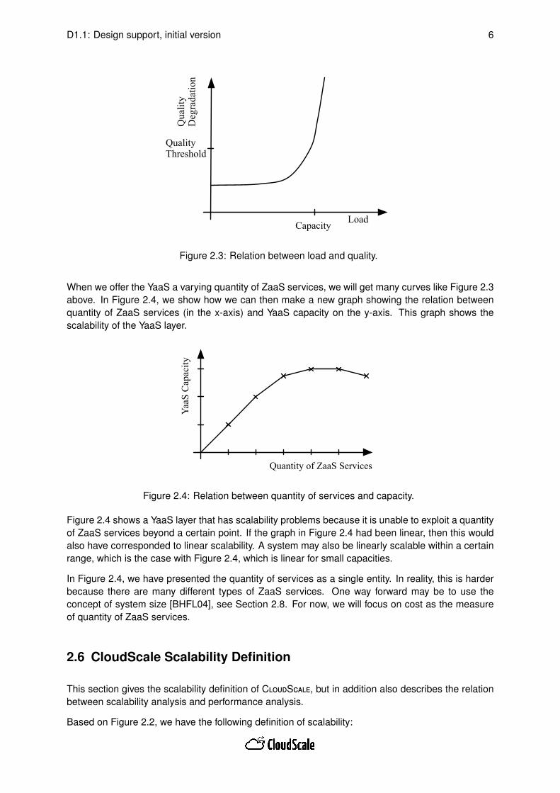
We now assume that a YaaS is always using the same quantity of underlying ZaaS services andthat there is no adaptation in the YaaS. In this case, Figure 2.3 illustrates how the quality graduallydegrades (on the y-axis) when we increase the load (on the x-axis). At some point, we reach thequality threshold (on the y-axis) and the corresponding point on the x-axis becomes the capacity ofthis system. We will later see that in addition to the load, we can also scale work as well as thequality threshold itself.
D1.1: Design support, initial version 6
Load
Qua
lity
Deg
rada
tion
Quality Threshold
Capacity
Figure 2.3: Relation between load and quality.
When we offer the YaaS a varying quantity of ZaaS services, we will get many curves like Figure 2.3above. In Figure 2.4, we show how we can then make a new graph showing the relation betweenquantity of ZaaS services (in the x-axis) and YaaS capacity on the y-axis. This graph shows thescalability of the YaaS layer.
Quantity of ZaaS Services
YaaS
Cap
acity
Figure 2.4: Relation between quantity of services and capacity.
Figure 2.4 shows a YaaS layer that has scalability problems because it is unable to exploit a quantityof ZaaS services beyond a certain point. If the graph in Figure 2.4 had been linear, then this wouldalso have corresponded to linear scalability. A system may also be linearly scalable within a certainrange, which is the case with Figure 2.4, which is linear for small capacities.
In Figure 2.4, we have presented the quantity of services as a single entity. In reality, this is harderbecause there are many different types of ZaaS services. One way forward may be to use theconcept of system size [BHFL04], see Section 2.8. For now, we will focus on cost as the measureof quantity of ZaaS services.
2.6 CloudScale Scalability Definition
This section gives the scalability definition of CloudScale, but in addition also describes the relationbetween scalability analysis and performance analysis.
Based on Figure 2.2, we have the following definition of scalability:

D1.1: Design support, initial version 7
For an Y as-a-Service, scalability is the ability of the layer to sustain changing workloadswhile fulfilling its SLA, potentially by consuming a higher/lower quantity of ZaaS services.
By saying potentially, we mean that there are also other possibilities. Currently, we are aware of twoother possibilities, and we discuss them for increasing workload:
Adaptation By adaptation in the YaaS layer that reduces the workload on ZaaS. We may, for ex-ample, change the version of one component to a component that uses less ZaaS services.To make this into a realistic scenario, there must also be some snag with this new component,otherwise it would always be used, e.g., it may for example be more costly or have pooreravailability etc.
Over-provisioning YaaS has some degree of over-provisioning, either because the YaaS servicesit is using has room for more workload, or because it for some reason uses more than therequired quantity of services from ZaaS. In both cases, it can, therefore, handle increasingworkload by reducing this over-provisioning.
As an effect of both these two other possibilities, the SLA with its quality threshold, will be lesssensitive to changes in workload.
The scalability definition above covers both workload growth and reduction in workload. Workloadgrowth is most common. Scalability is however also relevant when the workload is reduced, andwhere it is important to reduce the consumption of lower level services. An increasing degree ofover-provisioning with decreasing workload is not optimal because provisioning of ZaaS serviceshas a cost. In Section 5.4 we describe this relation, from provisioning of ZaaS services, to cost inmore detail.
Compared to performance analysis, scalability analysis has a more explicit focus on change inworkload, as well as on change in the consumption of lower-level services. Figure 2.3 will typicallyrepresent the performance of a layer, while Figure 2.4 represents scalability of the same layer. Asalso illustrated in these two figures, during performance analysis, the quality threshold is often aresult of the analysis, while the result of a scalability analysis is the quantity of underlying services.Of course, what we here term scalability analysis may also have been performed under the umbrellaof performance analysis or capacity planning earlier. But we will still argue that the explicit focus onchange in workload as well as on change in consumption of lower-level services is something new.
2.7 Elasticity
We use the following definition of elasticity, based on [HKR13]:
For an as-a-Service layer, elasticity is the degree to which the layer is able to adapt toworkload changes by (de)provisioning services of its underlying layers in an autonomicmanner such that at each point in time the utilised services fulfil the SLOs of the layeras closely as possible.
While scalability is mostly a feature of a service itself, elasticity is mostly a feature of the underlyingservices. Scalability describes a relation between service workload and the amount of underlayingservices consumed. Elasticity describes the ability for the underlying services to offer a higher orlower amount of itself. Even a services which scales well will have troubles if the underlying servicesare not elastic. On the other hand, a service with poor scalability will face problems, at least withcost, and possibly also with fulfilling its SLAs, no matter how elastic the underlying services are.Concerning metrics for elasticity, inspiration can be found in [HKR13].
D1.1: Design support, initial version 8
2.8 Related Work On Scalability Concepts
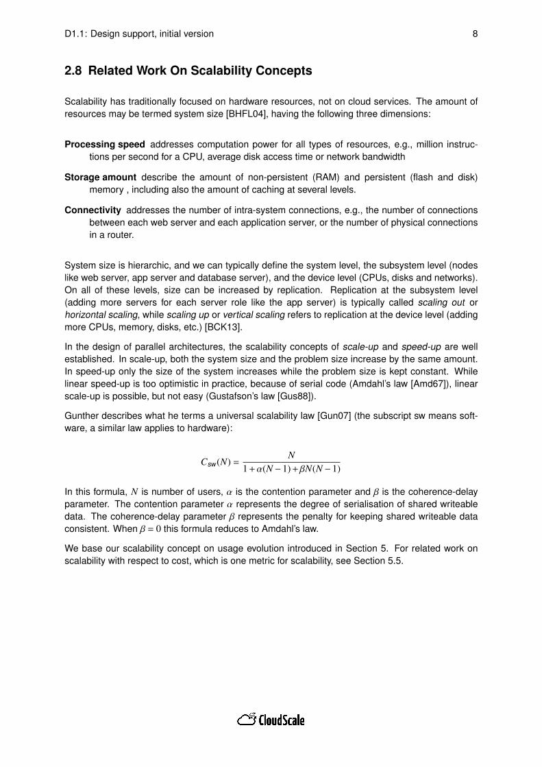
Scalability has traditionally focused on hardware resources, not on cloud services. The amount ofresources may be termed system size [BHFL04], having the following three dimensions:
Processing speed addresses computation power for all types of resources, e.g., million instruc-tions per second for a CPU, average disk access time or network bandwidth
Storage amount describe the amount of non-persistent (RAM) and persistent (flash and disk)memory , including also the amount of caching at several levels.
Connectivity addresses the number of intra-system connections, e.g., the number of connectionsbetween each web server and each application server, or the number of physical connectionsin a router.
System size is hierarchic, and we can typically define the system level, the subsystem level (nodeslike web server, app server and database server), and the device level (CPUs, disks and networks).On all of these levels, size can be increased by replication. Replication at the subsystem level(adding more servers for each server role like the app server) is typically called scaling out orhorizontal scaling, while scaling up or vertical scaling refers to replication at the device level (addingmore CPUs, memory, disks, etc.) [BCK13].
In the design of parallel architectures, the scalability concepts of scale-up and speed-up are wellestablished. In scale-up, both the system size and the problem size increase by the same amount.In speed-up only the size of the system increases while the problem size is kept constant. Whilelinear speed-up is too optimistic in practice, because of serial code (Amdahl’s law [Amd67]), linearscale-up is possible, but not easy (Gustafson’s law [Gus88]).
Gunther describes what he terms a universal scalability law [Gun07] (the subscript sw means soft-ware, a similar law applies to hardware):
Csw(N) =N
1+α(N −1)+βN(N −1)
In this formula, N is number of users, α is the contention parameter and β is the coherence-delayparameter. The contention parameter α represents the degree of serialisation of shared writeabledata. The coherence-delay parameter β represents the penalty for keeping shared writeable dataconsistent. When β = 0 this formula reduces to Amdahl’s law.
We base our scalability concept on usage evolution introduced in Section 5. For related work onscalability with respect to cost, which is one metric for scalability, see Section 5.5.
D1.1: Design support, initial version 9
3 CloudScale Method
This section describes the CloudScale Method. The method describes how to model self-adaptiveelastic services. Moreover, it also gives advice on how to develop scalability models, which canbe used for "what-if" analysis. The overall CloudScale Method is a collection of concrete processsteps required to engineer scalable cloud systems. CloudScale Method describes how to modelscalability both during design and during evolution of cloud systems. It also defines the input of ascalability model and what output can be produced based on this input. Finally, in later version ofthis deliverable, the method will also describe the effort involved in each process step and givesadvice on model granularity.
3.1 Method Overview
The key to the development of scalable cloud applications is an appropriate engineering method forthe scalability. Initially, a service provider has an idea for an application which he wants to execute inthe cloud because of the cost-efficient management and the virtually unlimited amount of hardwareresources. The service provider wants to ensure that the application scales cost-effectively, i.e., thatit always tries to cope with its workload with the minimum amount of cloud resources (measured interms of costs paid for the resources).
To enable sustainable engineering method for scalable cloud applications it is important to supportthe complete application life-cycle. The proposed CloudScale Method builds on an overall systemlife-cycle process from initial requirements collection towards operation and monitoring process.
3.2 CloudScale Method Scenarios and Basic Elements
CloudScale provides an engineering method for building (evolving) and adapting scalable cloud ap-plications and services. We focus on two core scenarios:
Development: Enabling software engineers to develop scalable applications and services for acloud computing platform. We extend existing capacity planning tools for scalability analysis,and introduce ScaleDL Usage Evolution to describe, compare, and compose the scalability ofservices. We also provide a set of best practices and design-patterns for building scalablesoftware systems.
Evolution: Enabling software engineers to evolve an existing software system or service into asolution that scales in cloud computing environments. We introduce a novel approach forscalability evaluation of existing systems by systematic experimentation using existing load-testing tools or making experiments on the models. This approach allows for scalability anti-pattern detection in an existing application and for extracting scalability models.
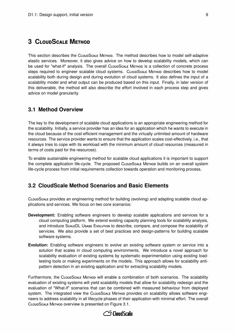
Furthermore, the CloudScale Method will enable a combination of both scenarios. The scalabilityevaluation of existing systems will yield scalability models that allow for scalability redesign and theevaluation of "What-if" scenarios that can be combined with measured behaviour from deployedsystem. The integrated view the CloudScale Method provides on scalability allows software engi-neers to address scalability in all lifecycle phases of their application with minimal effort. The overallCloudScale Method overview is presented on Figure 3.1.

D1.1: Design support, initial version 10
(1) Requirements Identification
(2) System Construction and Analysis
(4) Deployment
(5) Operation
(6) Monitoring
(Scalability) Requirements
ScaleDL
Specification
Start
AnalyserOutput
Requirements met?
CloudScale Architectural
Templates
Extractor
System Model / ScaleDL Instance
Existing System
Reverse Engineering?
yes
(Re-)Design System
no
Analyser&
Static Spotter
no
Legend
DocumentProcess DecisionStartTool-driven
Process
Data & Control flow Data flow
SpottingByMeasuring
Anti-Patterns & Solutions
Dynamic
Spotter
Realisation Directive
Deployment Directive
(3) Realisation
Realised
System
System operational parameters
Apply Anti-Pattern Solution
Solution Available?
yes
no
Realise SystemDeploy System
yes
Deployed
System
Figure 3.1: CloudScale Method Overview.
On the bottom of the figure is a legend explaining the notation. It is important to form clear processsteps which cover essential service life-cycle steps like Requirements, Design, Realisation, Oper-ation and Monitoring. It is also important to show the data and control flow between the processsteps. The most important service life-cycle steps are additionally elaborated with supported toolsand intermediate documents. To enable experimentation and iterative construction and analysiscycles, a couple of decision points for control and data flow were introduced (e.g., a decision stepwhere we determine if scalability requirements are satisfied after system modelling and analysis).Additionally, the method enables solution check after each service life-cycle steps and then returningto the analysis step to optimise the constructed service.
The basic processes in CloudScale Method are standard development processes in software devel-opment. We make some changes in the naming of processes to have more focus on the specificneed of the CloudScale Method. The first defined process is Requirements identification, becausethe CloudScale Method will specifically deal with scalability issues in the system development oradaptation, and will be integrated with some other general accepted engineering method for re-quirements engineering. However, it may also be executed independently. This process is definedbecause we must always annotate and define scalability requirements for the analysed system. Dur-ing the Requirements identification process, the main focus is on describing the evolution of load andwork. The quality metric describes what is acceptable system quality to the users, e.g., a particularresponse time. For example, we may expect used service response time in less than one second.This process results in a requirement specification document that is visible as ScaleDL Usage Evo-lution Specification. This output document of the Requirements Identification process is used likemain input in the System construction and Analysis process.

D1.1: Design support, initial version 11
Based on this requirement specification, the process System Construction and Analysis starts wherewe will use a model for specifying the system. We can do this in two ways:
1. By Reverse Engineering using an existing code base for creating an initial or adapting anexisting system model. This process is driven by our tool Extractor.
2. By (Re-)Designing a system on the model level using our Analyser tool. For specifying thismodel, we will use the ScaleDL Usage Evolution and Palladio Component Model (PCM), seeSection 7.
We guide our design decisions along the requirements specification and support it with known pat-terns for good architectures regarding scalability in cloud environments by using ScaleDL Architec-tural Templates. The output document from Extractor or newly designed system that will support(Re-)Design of system will be unified System Model that will be representation of ScaleDL Instanceas basic input for Analyser and Static Spotter tools. The next step involves the analysis of the mod-elled system to check whether it meets the identified requirements. This process is driven by ourAnalyser and Static Spotter tools as described in Section 3.4.3 and is repeated with different systemalternatives until the requirements are met. The main reason why we combine these two tools isbecause they logically do similar tasks. And development of these two tools is still in early stage andwhen clear tool inputs and outputs will be defined, we will update the CloudScale Method definition.If first model does not satisfy requirements we shall apply Spotter to make an analysis where wecan compare the Anti-Patterns & Solution based knowledge/parameters and Analyser driven outputparameters. Results from the Spotter is compared with Available Solutions and if we are satisfiedwith the proposed Solution we will apply an Anti-Pattern solution to create a new ScaleDL Instanceof the System model and go to the Analyser tool with new model. In the situation when the solutionis not available, we shall return to our construction and analysis process for improving the existingsystem model. This construction and analysis loop stops when system architect is satisfied with thesystem behaviour — when the requirements are met. The system construction and analysis processfinally ends by reaching satisfactory results about service scalability behaviour.
We may also find that our scalability requirements are infeasible and, therefore, we have to modifythem by reducing the complexity (and consequently work) of the services offered during the highload.
The two main outputs from the system construction and analysis process are the Realisation Direc-tive and the Deployment Directive. These two directives form the basis to continue with next stepsin software applications life-cycle called Realisation and Deployment.
The Realisation Directive can be used to automatic code generation in the Realisation process,either based on a developed system model or for semi-automatic code generation. The DeploymentDirective contains essential requirements/parameters for services deployment, which is required tosatisfy required system behaviour. In some situations, output from the System Construction andAnalysis process can be only a deployment directive, e.g., in cases when we use only existing andalready developed service components, and when we define only parameter reconfigurations foreach component, which determine the service deployment process.
Based on a Realisation Directive we start to implement our system. The output of system realisationis a Realised System prepared for deployment.
When the Realisation process step is finished, we move to Deployment. In the Deployment processstep, the application is deployed according to the Deployment Directive, and put in operation in acloud computing environment. For operation it is important to specify well-defined resource require-ments that enable cloud computing provider to efficiently provide cloud resources and to fulfil load,work and quality requirements of the deployed application reflecting the application evolution.

D1.1: Design support, initial version 12
Monitoring is another process step that is active during the system operation and enables controlof system behaviour. Collecting measurements for scalability parameters also belongs in this step.Based on the operational parameters and system quality metrics, monitoring control can requiresome changing system requirements and triggering the need to rerun our process cycle (adaptationloop).
Based on systematic experiments, enabled with the SpottingByMeasuring process, software engi-neers will receive the information needed to assess costs, identify scalability problems, and addresssuch problems accordingly. This will address both deployment evolution as well as architectural evo-lution. In the area of identification of scalability anti-patterns, CloudScale will identify and formalisescalability anti-patterns for cloud applications and provide a tool-supported method to detect thesepatterns on existing code-bases.
3.3 CloudScale Method Roles and Stakeholders
In the previous overall CloudScale Method description we have mainly used the role of softwareengineer, but it is important to emphasise that in the proposed method we envision four basic rolesfor the software engineer:
Product manager Person responsible for discussing with the customer of our service and iden-tify initial system requirements and define development goals especially from the businessperspective. The product manager is always active during the decisions regarding the require-ments fulfilment and business potential of the solution, i.e., in the Requirements identificationand System Construction and Analysis process steps.
System architect Person responsible for Requirements Identification and the main driver of SystemConstruction and Analysis. This role cooperates with Product manager and Service developerand its main responsibilities are architecture definition and to propose the main service com-ponents.
Service developer Person responsible for service realisation (both development and test), and forpreparing the system deployment process. This role cooperates with System architect forchecking realised services and with System engineer in preparing system deployment.
System engineer Person responsible for service deployment and monitoring of the system in op-eration. Based on monitoring results, the system engineer tends to optimise system operationparameters or to run the SystemConstruction and Analysis process step if it is not possible tofix system by fine tuning. System engineer cooperates with all other roles during the systemlife-cycle.
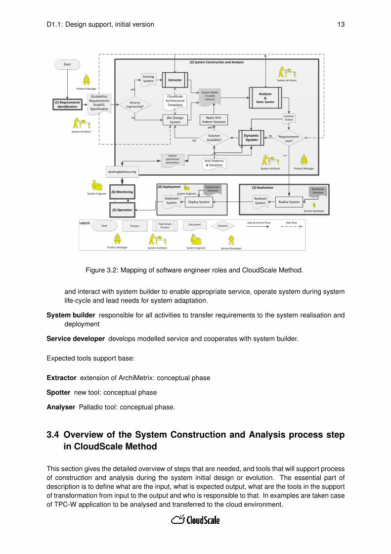
Basic mapping of roles and CloudScale Method is presented on Figure 3.2.
Looking from the perspective of CloudScale Method usage, we can define four basic system stake-holders1:
Service consumer wants to have supplied services for own purpose according to business needsand according an agreed SLA.
Service provider responsible to fulfil SLA and other requirements towards service user (accordingto cloud services it can be IaaS, PaaS or SaaS provider), preparing service requirements
1More detailed description of stakeholders and interaction between CloudScaleMethod steps and roles will be providedin the next version of the document.
D1.1: Design support, initial version 13
LegendDocument
Process DecisionStartTool-driven
Process
Data & Control flow Data flow
$$
Product Manager System Architect System Engineer Service Developer
(1) Requirements Identification
(2) System Construction and Analysis
(4) Deployment
(5) Operation
(6) Monitoring
(Scalability) Requirements
ScaleDL
Specification
Start
AnalyserOutput
Requirements met?
CloudScale Architectural
Templates
Extractor
System Model / ScaleDL Instance
Existing System
Reverse Engineering?
yes
(Re-)Design System
no
Analyser&
Static Spotter
no
SpottingByMeasuring
Anti-Patterns & Solutions
Dynamic
Spotter
Realisation Directive
Deployment Directive
(3) Realisation
Realised
System
System operational parameters
Apply Anti-Pattern Solution
Solution Available?
yes
no
Realise SystemDeploy System
yes
Deployed
System
$$
Product Manager
System Architect
System Engineer System Engineer
Service Developer
System Architect
$$
Product Manager
System Architect
Figure 3.2: Mapping of software engineer roles and CloudScale Method.
and interact with system builder to enable appropriate service, operate system during systemlife-cycle and lead needs for system adaptation.
System builder responsible for all activities to transfer requirements to the system realisation anddeployment
Service developer develops modelled service and cooperates with system builder.
Expected tools support base:
Extractor extension of ArchiMetrix: conceptual phase
Spotter new tool: conceptual phase
Analyser Palladio tool: conceptual phase.
3.4 Overview of the System Construction and Analysis process stepin CloudScale Method
This section gives the detailed overview of steps that are needed, and tools that will support processof construction and analysis during the system initial design or evolution. The essential part ofdescription is to define what are the input, what is expected output, what are the tools in the supportof transformation from input to the output and who is responsible to that. In examples are taken caseof TPC-W application to be analysed and transferred to the cloud environment.
D1.1: Design support, initial version 14
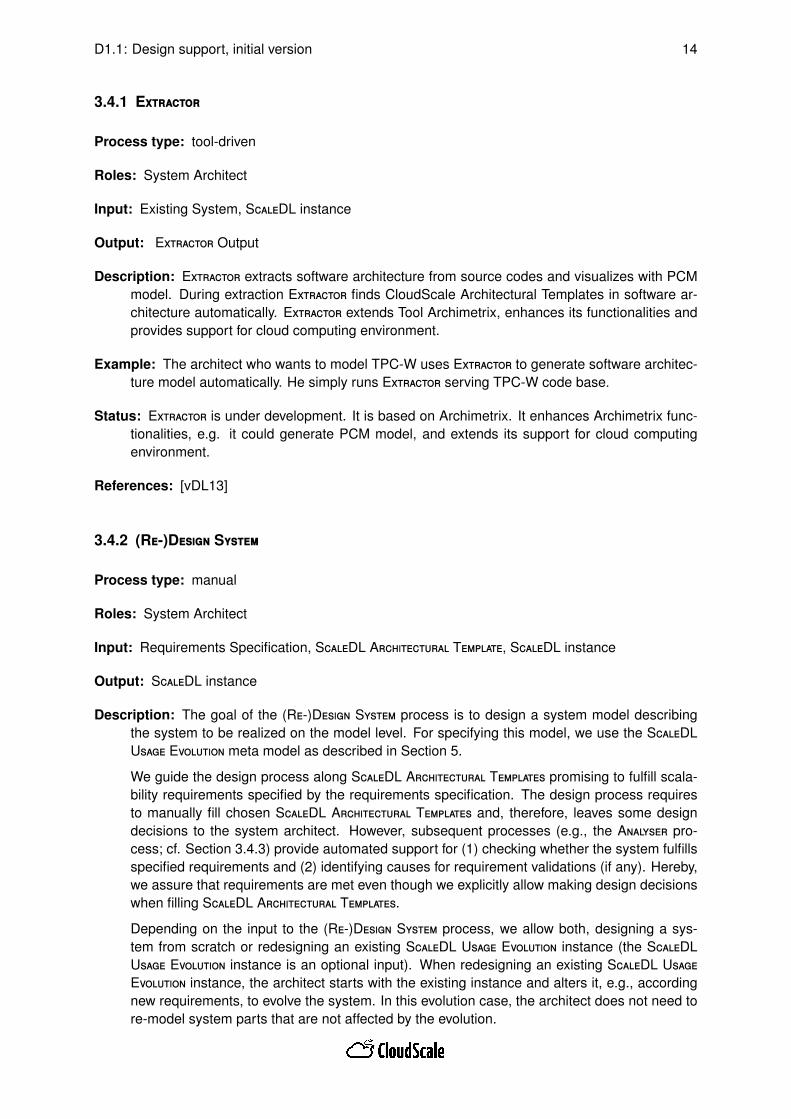
3.4.1 Extractor
Process type: tool-driven
Roles: System Architect
Input: Existing System, ScaleDL instance
Output: Extractor Output
Description: Extractor extracts software architecture from source codes and visualizes with PCMmodel. During extraction Extractor finds CloudScale Architectural Templates in software ar-chitecture automatically. Extractor extends Tool Archimetrix, enhances its functionalities andprovides support for cloud computing environment.
Example: The architect who wants to model TPC-W uses Extractor to generate software architec-ture model automatically. He simply runs Extractor serving TPC-W code base.
Status: Extractor is under development. It is based on Archimetrix. It enhances Archimetrix func-tionalities, e.g. it could generate PCM model, and extends its support for cloud computingenvironment.
References: [vDL13]
3.4.2 (Re-)Design System
Process type: manual
Roles: System Architect
Input: Requirements Specification, ScaleDL Architectural Template, ScaleDL instance
Output: ScaleDL instance
Description: The goal of the (Re-)Design System process is to design a system model describingthe system to be realized on the model level. For specifying this model, we use the ScaleDLUsage Evolution meta model as described in Section 5.
We guide the design process along ScaleDL Architectural Templates promising to fulfill scala-bility requirements specified by the requirements specification. The design process requiresto manually fill chosen ScaleDL Architectural Templates and, therefore, leaves some designdecisions to the system architect. However, subsequent processes (e.g., the Analyser pro-cess; cf. Section 3.4.3) provide automated support for (1) checking whether the system fulfillsspecified requirements and (2) identifying causes for requirement validations (if any). Hereby,we assure that requirements are met even though we explicitly allow making design decisionswhen filling ScaleDL Architectural Templates.
Depending on the input to the (Re-)Design System process, we allow both, designing a sys-tem from scratch or redesigning an existing ScaleDL Usage Evolution instance (the ScaleDLUsage Evolution instance is an optional input). When redesigning an existing ScaleDL UsageEvolution instance, the architect starts with the existing instance and alters it, e.g., accordingnew requirements, to evolve the system. In this evolution case, the architect does not need tore-model system parts that are not affected by the evolution.

D1.1: Design support, initial version 15
Example: An architect is ordered to design an elastic TPC-W system from scratch. The "scalabilityrequirement" is specified in the requirements specification: the system should be capable ofresponding in less than 3 seconds for user arrival rates between 1 and 60 users per hour. Asa starting point, he decides to develop the system for AWS Elastic Beanstalk (being an elasticPaaS environment). To do so, the architect creates a new ScaleDL Usage Evolution instanceand instantiates the ScaleDL Architectural Template specific to AWS Elastic Beanstalk. There-fore, he has only to complement the template with the missing web, application, and data logic.For instance, the architect provides components for (1) creating a UI for best selling books, (2)the application logic that fills the UI, and (3) a database query used by the application logicto receive a random set of five best selling books. On the model level, he only models thescalability-relevant behavior of these components. For instance, he annotates the applicationlogic to be stateless. The architect is not required to cope with other issues as, e.g., handlingthe database connection or setting up load balancers. Scalability-relevant information aboutthese issues are included in the ScaleDL Architectural Template and allow, e.g., the Analyserto predict whether the elasticity requirements are actually met.
Status: The "(Re-)Design System" is described on a high level of abstraction. More details areplanned for M24, i.e., once the complete CloudScale Method has been applied on first exam-ples.
References: The initial idea of the (Re-)Design System process are sketched in [BSL+13].
3.4.3 Analyser and Static Spotter
Process type: tool-driven
Roles: System Architect
Input: Requirements Specification, ScaleDL Usage Evolution instance
Output: Analyser and Static Spotter Output
Description: Analyser and Static Spotter process analyses a modelled system (ScaleDL Usage Evo-lution instance) to check whether it meets the scalability requirements of the requirement spec-ification. The Analyser is a tool that can automatically execute these checks and Static Spottercan detect scalability issues on model level.
To do so, outputs of this process are scalability predictions for the modelled system. Based onthis first output, Analyser can further output whether a requirement is met or not, respectively.In case it is not met, additional analyses can automatically be executed by Static Spotter todetect the causes for that (e.g., Static Spotter identifies a guilty component).
Example: The architect who modeled the TPC-W system via a ScaleDL Usage Evolution instanceexecutes the Analyser on this instance. The elasticity requirement specified in the requirementspecification is checked (the system should be capable of responding in less than 3 secondsfor user arrival rates between 1 and 60 users per hour). The Analyser then predicts whetherthe requirement is met or not.
Status: Analyser is currently in a conceptual phase. It will be based on Palladio and SimuLizar. Thefirst prototype allowing to analyse a simple example will be available at M12. Static Spotter isalso currently in a conceptual phase.
References: • The initial ideas of the (Re-)Design System process are sketched in [BSL+13].
• Sec. 3.4.3 provides details about the Analyser’s output.
• Chap. 7 describes the Analyser in detail.

D1.1: Design support, initial version 16
3.4.4 Dynamic Spotter
Process type: tool-driven
Roles: System Architect
Input: System Model or Analyser Output, ScaleDL Usage Evolution instance
Output: Dynamic Spotter Output
Description: Dynamic Spotter is a tool which finds components which are responsible for hinderingperformance by inspecting software architecture and codes. If these responsible componentsfit certain anti-patterns, Dynamic Spotter also suggests solutions automatically. Dynamic Spotteruses System Model or Analyser Output as an input with proper system operational parametersand works with running system.
Example: After Analyser and Static Spotter find that System Model does not fulfil Requirements, thearchitect runs Dynamic Spotter to locate "bad" components. Dynamic Spotter inspects SystemModel and codes. When Dynamic Spotter finds anti-patterns in the existing system, it alsosuggests solutions to alter the flawed software architecture or codes. The architect choosesone of the suggested solutions and Dynamic Spotter applies the change automatically.
Status: Dynamic Spotter is currently in a conceptual phase.
References: [WHH13]
3.5 Future Work on CloudScale Method
This deliverable presents initial CloudScale Method concept. The following topics will be covered infuture work on CloudScale Method:
CloudScale Method validation: CloudScale Method and CloudScale Method steps will be validatedusing industrial use cases (SAP and ENT) and showcase (XLAB).
CloudScale Method process steps refinement: When more detailed description of CloudScale toolswill be produced (e.g., detailed specification for each tool input/output), we will refine ourCloudScale Method according to these parameters.
CloudScale Method process steps detailed descriptions: Each CloudScale Method step will bepresented in more detailed way (e.g., Deployment step will be covered by definitions for Can-didate Platform selections, Target Platform testing etc.).
Model boundaries definition: We will define, for each CloudScale Method segment, the type ofsystem model that is present in that segment. The possible system models are:
• Cloud Independent Model (CIM)
• Cloud Provider Independent Model (CPIM)
• Cloud Provider Specific Model (CPSM)
and they will describe and represent the state of ScaleDL Overview (CSM) and type of datathat it contains in the specific segment of CloudScale Method.

D1.1: Design support, initial version 17
4 ScaleDL
The Scalability Description Language (ScaleDL) is a language to characterize cloud-based systems,with a focus on scalability properties. ScaleDL consists of four sublanguages: three new languages(ScaleDL Usage Evolution, ScaleDL Architectural Template, and ScaleDL Overview) and one reusedlanguage (Palladio’s PCM extended by SimuLizar’s self-adaption language). For each of these sub-languages, we briefly describe its purpose and provide a reference to a detailed description:
ScaleDL Usage Evolution allows service providers to specify scalability requirements, e.g., usingcost metrics, of their offered services (cf., Chap. 5)
ScaleDL Architectural Template allows architects to model systems based on best practices as wellas to reuse scalability models specified by architectural template engineers (cf., Chap. 6)
ScaleDL Overview allows architects to model the structure of cloud-based architectures and its de-ployment at a high and user-friendly level of abstraction (cf., Chap. 4 of deliverable D3.1)
Extended PCM allows architects to model the internals of the services: components, components’assembly to a system, hardware resources, and components’ allocation to these resources(cf., Sec. 7.2); the extension allows additionally to model self-adaptation: monitoring specifi-cations and adaptation rules (cf., Sec. 7.3)
Architects can use the Analyser to automatically analyze a modeled system with ScaleDL. This anal-ysis allows architects to check whether a system meets its scalability requirements stated via aScaleDL Usage Evolution instance. We detail the Analyser in Section 7.

D1.1: Design support, initial version 18

D1.1: Design support, initial version 19
5 ScaleDL Usage Evolution
The overall task for ScaleDL Usage Evolution is to enable the characterisation of scalability require-ments for a service. Using ScaleDL Usage Evolution, the System Architect can specify all the relevantinformation about the expected usage and quality thresholds. It will the be possible to perform scal-ability analyses using Analyser (or any other tools). Looking at Figure 2.2, ScaleDL Usage Evolutionwill characterise the usage interfaces between XaaS and YaaS.
This chapter first describes an overall scenario for ScaleDL Usage Evolution. We will then describethe basic building stones of the ScaleDL Usage Evolution, Deployment is characterised in Section 5.3.Based on workload and deployment characterisation, we define scalability in Sec. 5.4. We will thendescribe a first sketch of a meta model for ScaleDL Usage Evolution. Finally, we present some futurework. We will use the TPC-W application described in D5.1 as a running example.
5.1 Overall Scenario for Usage Evolution
CloudScale will primarily assist the scalability engineering of projected or existing SaaS services.This scenario presents the basic question which shall be answered by the ScaleDL Usage Evolution.Input from the industrial partners ENT and SAP was invaluable in the formulation of this scenario.The overall usage evolution scenario is:
I anticipate a change in work, load or quality threshold somewhere in the future. Whatwill the consequences be?
We will now detail what this means, and we in addition to the TPC-W example from D5.1 we will usethe EHR (Electronic Health Record) case study from ENT in D4.1 for illustration.
Concerning the change itself this may have many forms:
Peaks in load because of bird flu or migration to a larger market, for example moving an EHRapplication from Croatia to a larger market in Germany or even in Pakistan.
A gradual increase in load resulting from a steady increase in the number of consumers.
Lower load because of summer vacation or week ends.
Increase in data sizes , representing more work as described in Section 2.2. In the context ofTPC-W, typical data is books and customers, so this will then mean an increasing number ofeither books, customers or both. For EHR the average size of health records may increase forexample because of self administered heart measurements.
Harder quality thresholds for example because of increased competition.
New services which are either designed from scratch or redesigned.
Changes in key components inside the service.
Changes in the PaaS environment for example a new DBMS.

D1.1: Design support, initial version 20
All of these except the latter three concerns the usage evolution. New services will be considered inthe same way as existing services. Changes in the service itself has to do with variability describedin Section 2.4. Changes in the PaaS layer concerns deployment and is described in Section 5.3.
When considering how to represent usage evolution it is of coarse also relevant to know what wewant to know as a result of the scalability analysis. The most basic question to answer in the contextof scalability is the following:
Are we able to handle this (given our SLA)?
This question is of course only relevant for an increase in load or work, or for tougher quality thresh-olds. Then next natural question is:
How much will it cost in terms cost of invoked underlaying services?
This question is also relevant for a decrease in load or work or for softer quality thresholds, becausethen it is important to know how much the cost will be reduced as a result of this decrease.
If we are not able to handle an increasing demand it is relevant when this point of SLA violation andunder provisioning is reached. We may also formulate several questions concerning migration to thecloud, but this will not be considered now. Using case studies we are able to find out how detailedthe usage evolution needs to the modelled to answer these questions appropriately.
5.2 Usage Evolution Formalisation
Usage evolution specify scalability requirements by characterising how the workload of a servicechanges over time.
We first describe the starting point, which we simply term initial usage in Section 5.2.1. Afterwards,we elaborate the evolution in time for these profiles in Sec. 5.2.2.
5.2.1 Initial Usage
An application provides one or more operations as a service. For each of these operations, theconcept of initial usage specifies:
Operation parameters: Operation parameters characterise the amount of data to be processed,stored or communicated. This amount of data may vary for each invocation of the operation,but it may also be constant for many invocations. Operation parameters can also provide aninput for the process in which we define the work of each operation. If we apply this conceptto the TPC-W case study, we can specify two operation parameters: (1) "number of books inthe database" that stays constant and (2) "number of customers in the database" that variesduring the service life cycle.
Load: For an open systems, load can be measured in terms of the arrival rate. An arrival rate isvalid during a specified time interval. For a closed system, load can be characterised by thenumber of simultaneous customers. As it is a closed system, this number does not changeover time, i.e., it stays constant. We model TPC-W as an open system and use a monthly timeinterval.

D1.1: Design support, initial version 21
Quality metric: Each operation must have quality metrics that describe how it is evaluated. Averageresponse time is a common quality metric.
Quality threshold: For each operation with a certain quality metric, one or more quality thresholdscan be specified such that they identify the border between acceptable and non-acceptablequality, e.g., 3 seconds for an average response time quality metric.
Quality metrics and quality thresholds have been described in more detail in Section 2.3.
The initial usage of an SaaS application is specified by the domain expert (of the SaaS customerdomain) together with the architect of the SaaS application. For the TPC-W operations, the TPCspecifies three different initial usage scenarios [Cou02]: (1) "Browsing" where customers mainlyrummage through the book shop, (2) "Ordering" where customers heavily order books, and (3)"Shopping" as a combination of the previous configurations.
5.2.2 Characterisation of Evolution
In this section we are describing how to capture the evolution of the initial usage in Section 5.2.1.This has parallels in teletraffic forecasting [Ive10]. To generalise from the scenario in Section 5.1,we are interested in two basic forms of usage evolution:
Stable corresponding to fairly constant load, work and quality thresholds.
Gradual change corresponding to a book-selling company that slowly but steadily becomes moreand more popular and where both the load in terms of arrival rate as well as the number ofbooks grow at a regular, but slow pace. We may also the a gradual decrease.
To model a gradual change we first need to know the staring point. A gradual change may basicallybe formulated in two ways:
Linear where we need to know the rate of increase with respect to the staring point. As an examplewe may start with 1 000 consumers and then get 100 more consumers every month. After oneyear we then have 2 200 consumers.
Exponential where the rate of increase is compared to the previous period and not to the startingpoint. For example so that we always increase the number of users by 10 % compared to theprevious month. If we then start with 1 000 consumers, we will after one year reach more than3 100 consumes.
While the simple case has only one type of gradual change, we may of course also have severaltypes of gradual changes, for example first a fairly slow increase, but then a faster rate of increase,before we enter a mature marked which is stable (a typical S curve).
In both these evolution patterns (stable and gradual change), we may also have sudden changesor spikes, for example representing a book-selling service that must cope with a high load beforeChristmas. It may also represent a sudden increase in load for a service which is placed in a new,larger market. For these two cases the duration of the spike varies considerably. The duration ofthe Christmas shopping spike may be measured in weeks, whereas the change in marked in theorymay last forever. In the case of the Christmas shopping spike we also have the frequency of onceevery year, whereas frequency is not relevant for the new market case. Even if the concept of spikeis vital for scalability, the importance of the concepts of duration and especially frequency is moreunclear at the moment. This will be clearer when we get feedback from our case studies.

D1.1: Design support, initial version 22
You may be interested in more than one spike, but this is a simple generalisation. While spikes areby nature a sudden increase in demand, we may also have a sudden decrease in demand. We havenow discussed spikes in load, but we may of course also have sudden changes in work or in qualitythresholds. While the notion of time is implicitly present in the discussion of spikes above (frequencyand duration), we believe the absolute time of events happening is not relevant.
Especially for load, but also for work we face more or less variance. This variance may be modelledusing statistical distributions. For modelling the typical case we may use the average value and/orthe median value. A simple representation for variance capturers the following metrics in addition tothe average and/or median value: typical minimum and typical maximum. Using the word "typical"we exclude exceptions which are modelled as spikes. More sophisticated ways of modelling varianceare of course possible. On the other hand, we can also do this simpler, by only focusing on typicalmaximum, and simply ignore both average/median and typical minimum. Case studies will tell uswhat is the best abstraction level.
When modelling the future we may base ourself on historical data or educated guessing. Usinghistorical data we can easily see evolution during a day, a week or during a year. For example, loadfor an internet book store may aways be highest between 20 and 23 in the evening and there may bemore load during Christmas. We may also see differences in the daily load on weekdays comparedto the daily load during weekends. However, since we are interested in the general trend in additionto spikes, this detailed evolution is most likely not so interesting in our context.
5.3 Deployment Characterisation
The deployment profile characterises how an application uses lower-layer services. This will build onScaleDL Overview. For example, an SaaS application could use PaaS services such as databases,message queues, and monitors, but it may also use IaaS [Mea13]. The deployment characterisationis specified by the architect of the SaaS application.
On the market, there are many different services to select from. Therefore, architects need tocharacterise the services they are interested in, e.g., a particular Amazon EC2 instance type like a"general purpose, medium instance". In this case, replication of this particular instance type is theonly thing left to characterise. The architect may specify a larger set of configurations.
The architect must also determine important characteristics of the service deployment. Examplesare the number and types of indices in a DBMS. Concerning software contention, deployment deci-sions include buffer and pool sizes. For example, in TPC-W, the Database Connection componentcan be parametrised by the pool size for database connections, thus, crucially impacting the load onthe Database Server.
5.4 Cost Versus Service Scalability
This section describes the relation between scalability and cost as well as its relation to lower-levelservices. We will also gives some initial ideas on service composition.
We are now in a position to provide metrics for our scalability definition from Section 2.6. A scalabilityspecification can focus on services or on cost:
Scalability with respect to services is a metric which specifies the relation between usage evolu-tion for a service and the required quantity of lower-layer service.

D1.1: Design support, initial version 23
With only one deployment option (for example the m1.medium Amazon EC2 instance), thespecification will be a mapping from all the variables in the usage evolution down to the numberof services instances required to fulfil the required quality thresholds. If we will only vary loadin the usage evolution, then this may look like Figure 2.4. When we also consider differentwork parameters as well as quality thresholds, it will be more complex. With many differentdeployment options, such a characterisation may be even more complex both to evaluate andto represent.
Scalability with respect to cost is a metric which specifies the relation between usage evolutionfor a service and the cost. Cost is more important for SaaS providers than the actual servicedeployment option used. In this way, this specification is a simplification. Furthermore, costis also flexible, meaning that scalability with respect to cost will change regardless of actualchanges in either the workload or the deployment.
If we will only vary load in the usage evolution, then this may look like Figure 2.4, but where thex-axis is cost. When we also consider different work parameters as well as quality thresholds,it will be more complex.
ScaleDL Usage Evolution will at least be able to specify cost scalability. If required, service scalabilitywill also be supported.
Concerning composition scalability specification using ScaleDL Usage Evolution, we must at leasthandle the TPC-W case where we compose basic IaaS services as well as a payment SaaS service.To both these two layers we will also have network connections, so in total we will have the followingfour services:
• IaaS
• Network to IaaS
• Payment SaaS
• Network to the Payment SaaS service
For all these four services we may have several instance types to choose from, for example we mayhave three network instance types for the two networks and four instance types for the IaaS serviceand finally two instance types for the payment SaaS service.
When we know the usage evolution for the TPC-W application, the composition of these four servicescan then be a search process where we select the instance type with the lowest cost which still fulfilsthe SLAs. This search process may itself pose a scalability problem. For composition we may alsobuild on the concept of complexity specifications from SP [HL07]. SP describes how to composeseveral performance specifications, giving us conceptual ideas on how to compose ScaleDL UsageEvolution specifications for several services as well. However, a general description of scalabilitywith respect to services may also be large, given yet another scalability problem. How to practicallyhandle such composition will be part of the Analyser, described in Section 7.
5.5 Related Work on Scaling and Cost
We will primarily consider scalability related to cost. In this section, we describe the relation betweenour work and other similar work on scalability, which at the same time also considers cost. Jogalekarand Woodside [JW00] give a scalability definition where they combine throughput, average value of

D1.1: Design support, initial version 24
each response, and cost into the same metric. In contrast to this work, we describe how work,specified using operation parameters, load, and quality limits, can scale independent of each other.
Our view on scalability is more closely related to Duboc et al. [DLR13] who describe scalabilityassumptions conceptually as characteristics in the application domain. These characteristics, e.g.,workload, are expected to vary over time. We make our scalability assumptions explicit by describingthem as operations, operation parameters, and load. Furthermore, we describe how operations withoperation parameters characterise work. Duboc et al. also describe scalability goals much in thesame way as we do. In contrast to Duboc, we also tie scalability closely to service deployment andshow how scalability can be expressed both in terms of service quantities and in terms of servicecosts. This specialisation is required when describing the scalability of cloud applications.
Brebner and Liu [BL10] compute the actual cost and measure the real performance of a typicale-Business service using two types of workloads that all have spikes during a typical day. Theyconsider the cost for three different scenarios: in-house using a bare machine, in-house using virtu-alisation, and exploiting services of three different cloud computing providers (Amazon EC2, GoogleAppEngine, and Microsoft Azure). They also consider typical response times also including network-ing for these different scenarios. However, they do not provide a scalability definition, thus, makingit hard to reuse their ideas in a goal-oriented manner, i.e., towards a general, quantifiable scalabilityconcepts.
Kossmann, Kraksa, and Loesing [KKL10] compare the scalability of a TPC-W application usingthree different cloud services: Amazon AWS, Google AppEngine, and Microsoft Azure. They alsoconsider costs. In contrast to our work, they neither describe scalability using more than load nordefine scalability. Furthermore, they lack a focus on SaaS applications and concentrate on differentservice providers. We are especially interested in the scalability of SaaS applications.
5.6 Meta-model
Figure 5.1 shows the initial meta-model for ScaleDL Usage Evolution. Elements imported from thePalladio Component Model (PCM) are shown with package name from within PCM that they arespecified in.
The UsageEvolution meta-model is defined to allow specification of how the usage evolves over time.We have chosen to build the meta-model by focusing on what additional elements are required inorder to add support for usage evolution to the Palladio Component Model. Using this meta-model,usage evolution is modelled by first describing the initial usage, and then specifying the changesthat occur over time.
The root element of the model is the UsageEvolution element. The initial Usage elements describesthe initial configuration by referring to a UsageScenario from a PCM model, and by defining a set ofQualityThresholds defining for the usage. Definition of the initial operational parameters and loadare covered by the UsageScenario. In addition the initial Usage element of the UsageEvolution,additional Usage elements can be added to describe the evolution in a step-wise manner. Each ad-ditional Usage can contain a LoadChange and a set of OperationalParameterChange. A LoadChangeis described by either having a gradual change or a redefined workload:
• The GradualChange has a change factor by which the current load value should be multipliedwith for each time increment that is simulated. The change can either be linear (e.g. adding10 percent of the original value for each increment), or it can be exponential by multiplying thevalue from the previous time increment of the simulation.

D1.1: Design support, initial version 25
Figure 5.1: Draft meta model for ScaleDL.
• The redefinedWorkload uses a closed or open workload as defined in PCM to override thedefinition of the workload from the current UsageScenario of the UsageEvolution.
An OperationalParameterChange is similarly described by having either a gradual change or rede-fined variable usage:
• The GradualChange works in the same way as for load, using a factor by which the initial orprevious value of the variable should be multiplied.
• The redefined usage applies a VariableUsage (from PCM) to describe a variable usage thatwill replace the current/original variable usage definition within the UsageScenario
The OperationalParameterChange uses a Parameter to describe which operational parameter in theUsageScenario the change is defined for.
The QualityThreshold and QualityMetric is currently incomplete, and will be refined in the next ver-sion of this specification.
Note that at this point we have not made up a clear opinion on realisation, e.g., whether the ScaleDLUsage Evolution should "decorate" and refer to the PCM meta-model (like is done in the currentdraft), whether the current usage model of PCM should instead be updated to support the concepts,or whether ScaleDL Usage Evolution should be an independent, self-contained model that can bemapped/transformed to/from PCM.
The Workload concept is imported from PCM. PCM further defines OpenWorkload and ClosedWork-load as two concrete realizations of Workload. A closed workload has two properties: Work specifiedas an integer value, and think time specified as a stochastic expression. An open workload has thesingle property interArrivalRate that is specified as a stochastic expression.

D1.1: Design support, initial version 26
These concepts are relevant and usable for our concepts, and are implicitly reused through theimport of Workload. In the PCM meta-model, a UsageScenario is restricted to contain exactly 1Scenario Behavior and 1 Workload, that does not cover evolution over time.
5.7 Future Work on ScaleDL Usage Evolution
This deliverable has presented initial ideas on ScaleDL Usage Evolution. Our plans for the secondproject year will look into the following issues:
Complete version of ScaleDL Usage Evolution What we have presented here are initial ideas forScaleDL Usage Evolution. In the next year we will make a full, internally consistent version ofScaleDL Usage Evolution, which is also partially validated with the CloudScale case studies.This version of ScaleDL Usage Evolution must also more or less explicitly consider all the threedimensions of system size described in Section 2.8.
Fix open issues concerning quality metrics: Do we want to specify a set of pre-defined metrics,and/or do we want a meta-model that allows to defining new metrics? When defining a usageprofile, do we just pick from a pre-defined list of metrics and set the threshold at the sametime?
Handle self-adaptive elastic services As described in Section 2.4, we will base this on SimuLizar[BLB12, BBM13] together with inspiration from the MODAClouds [MOD13] EU project andconcepts from MUSIC [MUS10].
Compostion of scalability specifications for several services We have presented some initialideas in Section 5.4 which essentially makes this into a search process and where we alsosay that we may build on the complexity specification concept in SP [HL07].
Fix connection to the PCM meta model: In the PCM meta-model, there are, e.g., concepts forQoSAnnotations and SpecifiedExecutionTime (System and Component), but at this stage wehave not identified if these are applicable to the needs for describing quality metric in usageevolution.
Relation to MARTE In the further work on quality metrics, we will look into relevant parts of theMARTE specification [OMG11]. One relevant part of this can be the Non-functional PropertiesModeling (NFPs) (chapter 7 of the specification). Among the concepts from this that will bestudied in more detail are QuantitativeNFP, Measure, Unit Quantity, and Dimension. Anotherpart of the MARTE that may be relevant is Time Modeling (chapter 8 of the specification), andalso this will be investigated further.
Relation to SLA@SOI Other work that will be further investigated is the SLA@SOI. The top levelconcept in their SLA model is an SLA template that describes the agreement parties involved,the functional interface offered and required, and agreement terms. The latter includes pre-conditions under which the terms are effective, and includes guarantied states and actionsthat will be performed under specific circumstances. The concepts of guarantied states couldbe relevant to the quality threshold concept of the usage evolution meta model, whole the ac-tions could be relevant for support of adaptation. The SLA@SOI model is described in a bookchapter [SLA13].

D1.1: Design support, initial version 27
6 ScaleDL Architectural Template
In this chapter, we describe the concepts and the realization of the ScaleDL Architectural Template(AT) language – a sublanguage of ScaleDL (cf., Chap. 5, which is about another ScaleDL sublan-guage, ScaleDL Usage Evolution.). We define the AT language as follows: the ScaleDL Architec-tural Template (AT) language is a language to formalize architectural styles on component models.In particular, this formalization allows to enrich styles by quality annotations and completions formodel-driven quality analyses. Quality annotations characterize a concrete quality property of inter-est. Quality completions utilize these annotations to derive quality models that can be used as inputto quality analysis tools.
Because we focus on SaaS applications, we enrich ATs by scalability annotations and completions.Therefore, we enable architects to analyze their applications’ scalability based on our ATs. Thisanalysis is supported by our Analyser tool (cf., Chap. 7).
The AT language distinguishes between AT types and AT instances. With AT types, AT engineersspecify the formalization of an architectural style as well as its scalability annotations and comple-tions, i.e., they create an AT. In contrast, AT instances allow software architects to apply an ATto their component-based architecture. This application allows software architects to design andanalyze their architecture for scalability.
This chapter is structured as follows. First, Sec. 6.1 introduces a brief example scenario to motivateand illustrate the AT language. Based on this scenario, we describe the processes of AT creationand AT application in Sec. 6.2. Section 6.3 describes the abstract syntax of the AT language, i.e., itsmetamodel for AT types and AT instances, respectively. Afterwards, we give the concrete, graphicalsyntax of the AT language (for both, types and instances) in Sec. 6.4. In Sec. 6.5, we briefly list con-crete ATs we created and link to the location in the CloudScale Wiki where these ATs are describedin detail. Section 6.6 explains the naming "architectural template" based on related terms in soft-ware architecture. In particular, the latter section explains why we renamed the proposed "scalabilitybest practices" and "scalability patterns" of our DoW to ATs. Finally, we describe open issues andcorresponding future plans regarding the AT language in Sec. 6.7.
6.1 Example Scenario for Architectural Templates
As an example scenario, we consider a simplified book shop that shall be newly designed for runningin a cloud computing environment. In this scenario, an enterprise assigns a software architect todesign the book shop. The enterprise has the following requirements for this shop:
R1: Functionality In the shop, customers can (1) browse and (2) order books.
R2: Handling of Environmental Changes The enterprise expects that the environment for thebook shop changes over time. For example, it expects that books sell better around Christmaswhile they sell worse around the holiday season in summer. Therefore, the response times ofthe shop shall stay within 3 seconds even if the customer arrival rates in- or decrease by 1,000customers per hour (at maximum).
R3: Linear Cost Scalability The costs for operating the book shop are only allowed to increase(decrease) by $0.01 per hour when the number of customers using the shop increases (de-creases) by 1 per hour. Costs per hour is a metric to measure the amount of additionalservices (cf., the scalability definition in Sec. 2.6).

D1.1: Design support, initial version 28
Requirements R2 and R3 are typical reasons to operate a system in an elastic cloud computingenvironment, i.e., an environment where application servers automatically provision the requiredamount of services to cope with environmental changes. Therefore, the software architect will designthe shop as an SaaS application operating in a rented cloud computing environment. To provide ascalable SaaS application (R3), the architect considers using (1) architectural styles as well as(2) scalability analyses.
The first option (architectural styles) requires that the architect is aware of appropriate cloud-basedarchitectural styles as well as their application and assumptions. Currently, only a few architec-tural styles for SaaS applications in the cloud exist [EPM13]. One example for such a style isSPOSAD [Koz11].
SPOSAD suggests a 3-tier system with stateless middle tier, but leaves open the decision for a con-crete database paradigm on the data tier [Koz11]. Therefore, the architect may design the book shopas shown in Fig. 6.1: he assigns the three SPOSAD tiers (presentation, middle, data) to the cor-responding components (Book Shop Frontend, Book Management, Book Database), respectively.The tiers of SPOSAD can be seen as its roles, i.e., as set of constraints for associated components.For example, the data tier may only allow connections from the middle tier. As SPOSAD does notconstrain the data tier further, the architect is unsure whether to design the system with a rela-tional or a NoSQL database that both promise to scale differently. Because of this variability point(or parameter), he needs further guidance; SPOSAD alone is not enough. For achieving particularscalability requirements, there is, hence, the need to refine SPOSAD. Also the few other SaaS styleslack detailed suggestions for selecting an appropriate database paradigm.
Presentation Tier Middle Tier Data Tier
Book Management
Book DatabaseBook Shop Frontend
Customer
Legend:Component
Actor
Role Provided Interface
Required Interface
Assembly Connector $Parameter
$DB Kind = NoSQL
Figure 6.1: Model of the designed book shop scenario according to a simplified SPOSAD variant
The second option (scalability analyses) would allow the architect to model both database alterna-tives and to compare their scalability (what-if analysis). Scalability analyses require simulation oranalytical models allowing architects to predict an SaaS applications’ scalability in cloud computingenvironments. However, according to Becker et al. [BLB12], current analysis models lack (1) supportfor comprehensive design-time analyses based on architectural models, (2) realistic case studies incloud computing environments, and (3) explicit support for scalability because of their focus on per-formance analysis. These lacks hinder the architect to use and trust existing approaches in orderto analyze the scalability of the modeled book shop. For instance, these approaches are unable toanalyze whether a NoSQL or a relational database suits the enterprises’ scalability requirementsbest. Hence, these approaches need to be extended and improved.
The lack of guidance (regarding styles and scalability analyses) for the architect leads to the highrisk of realizing a cost-inefficient SaaS application and of an expensive re-implementation. For ex-ample, it may be expensive to refactor the book shop with an established but non-scalable relationaldatabase implementation to an implementation using a NoSQL database. This risk becomes evenmore crucial in case the enterprise discovers scalability issues when high costs for hosting theirapplication have already incurred, e.g., during system operation.

D1.1: Design support, initial version 29
6.2 Architectural Template Processes
To cope with the lack of guidance for software architects (cf., Sec. 6.1), we propose the AT language.Software architects can apply ATs (specified in the AT language) to design systems as well as toanalyze their scalability. AT engineers, on the other hand, create these ATs via the AT language. Weguide through these processes of AT application (Sec. 6.2.1) and AT creation (Sec. 6.2.2) by usingthe book shop scenario of Sec. 6.1.
6.2.1 Applying a SPOSAD Architectural Template
Software architects apply ATs to design SaaS applications and to analyze their scalability. Fig. 6.2illustrates the process steps for applying ATs. In step 1, architects select an AT from a repository ofATs. For example, the architect of the book shop scenario selects a SPOSAD AT. Afterwards, thearchitect assigns all roles the AT requires to the components of his architecture (step 2).
(1) Select AT(2) Assign AT Roles to System Components
(3) Analyze Scalability
Figure 6.2: Process steps of AT application for software architects.
As illustrated in Fig. 6.1, he may assign the roles of the SPOSAD architectural style (presentation,application, and data tier role) to book shop components as well as connects these componentsappropriately. Firstly, the AT formalism assures that no constraints are violated, e.g., it forbids con-necting presentation and data tier components. Secondly, the AT formalism allows architects tospecify whether a data tier component corresponds to a relational or a NoSQL database (a param-eter characterizing a variation point).
Because this design is based on an AT, the architect can run scalability analyses afterwards (step 3).The key idea is that the AT includes scalability annotations and completions for this purpose. Forthe book shop, the specification of the database parameter corresponds to a concrete scalabilityannotation. SPOSAD AT’s scalability completion then ensures that the architect obtains results thataccurately reflect the scalability of the selected database kind. Therefore, the SPOSAD AT allowsthe architect to analyze which kind of database better fits his scalability requirements at design time.
6.2.2 Creating the Architectural Template for SPOSAD
To create ATs, AT engineers apply the process illustrated in Fig. 6.3. In the first step, they formalizeAT roles (e.g., SPOSAD’s data tier) based on architectural styles (e.g., known from architecturehandbooks).
(1) Formalize Style with AT Roles
(2) Identify and Quantify Scalability
Parameters
(5) Enrich AT with Scalability Annotations
and Completions
(3) Specify Scalability Model
(4) Validate Scalability Model
Figure 6.3: Process steps of AT creation for AT engineers.
Besides formalizing architectural styles, AT engineers enrich the AT with scalability annotations andcompletions to enable an automated scalability analysis. The basis for this analysis is an accuratescalability model that can be used by scalability analysis tools. Therefore, AT engineers have to
D1.1: Design support, initial version 30
specify and validate such a scalability model based on identified and quantified scalability param-eters. Once AT engineers have created an accurate scalability model, they can enrich the AT withscalability annotations and completions allowing to automatically derive the scalability model fromcomponent-based architectures specified with the AT.
Accordingly, AT engineers first have to identify scalability-relevant parameters and quantify them(step 2). For example, the kind of database (e.g., a relational or a NoSQL database) on the data tiercould be a scalability-relevant parameter because NoSQL databases are often designed for scalinghorizontally. To confirm and quantify the influence on the scalability of this parameter empirically, anAT engineer (1) implements a series of automated test-drivers (focusing on the database parameter)that systematically collect the necessary data based on scalability metrics and (2) runs these test-drivers in a cloud computing environment. The AT engineer can subsequently check and quantifythe influence of the "kind of database" parameter by means of a regression analysis.
In case AT engineers successfully identified a scalability parameter, they specify a scalability modelfor this parameter (step 3). This scalability model particularly integrates the quantified results for theconsidered cloud computing environment. For the book shop example, the AT engineer has, e.g., tospecify a scalability model for NoSQL databases. Because NoSQL databases can scale horizontally,an accurate scalability model should model this NoSQL database as a "simple database" compo-nent that is attached to a "load balancer" component. As soon as load exceeds a certain threshold,an additional adaptation rule assures that another "simple database" component is served by an ad-ditional service and added to load balancing. To determine concrete thresholds of the load balanceras well as processing times of the "simple database" component, the AT engineer integrates theresults of the regression analysis. The scalability of this model can, finally, be analyzed by ordinaryanalysis tools supporting simple components annotated with processing times as well as adaptationrules, e.g., the PCM.
In the fourth step of Fig. 6.3, AT engineers validate the scalability model. For this validation, theyuse a set of case studies that particularly include identified scalability parameters. The book shopscenario can, for instance, be seen a possible case study. For each case study, AT engineers(1) measure its scalability in the considered cloud computing environment and (2) predict its scala-bility based on the scalability model. In case the predictions accurately reflect the scalability of themeasurements, the AT engineers successfully validated the model. Otherwise, they have to iteratethe process by refining the automated test-drivers or by identifying and integrating further scalabilityparameters.
In the final step of Fig. 6.3, AT engineers enrich the AT with scalability annotations and comple-tions. For example, the "NoSQL database" component assigned to the "data tier" role could betransformed to the "simple database" and "load balancer" components as described above. Accord-ingly, the specification of a "NoSQL database" for the "kind of database" parameter corresponds to ascalability annotation. The transformation to the "simple database" and "load balancer" componentscorresponds to a scalability completion. Therefore, the scalability of this model can, finally, be ana-lyzed by the Analyser (which lacks support for NoSQL databases but can cope with the PCM modelsresulting from the scalability completion).
We based the process of Fig. 6.3 on established processes in performance engineering [HFBR08].The basic idea is that concepts for performance engineering (e.g., performance model specificationand validation) apply similarly on scalability as well.

D1.1: Design support, initial version 31
6.3 Abstract Syntax: AT Metamodel
In this section, we describe the metamodel of the AT language, i.e., its abstract syntax. The mainAT language package is a subpackage of ScaleDL and includes two subpackages on its own: a typeand an instance package. The type package (Sec. 6.3.1) allows AT engineers to specify a new oralter an existing AT. The instance package (Sec. 6.3.2) allows software architects to apply a specifiedAT on a component-based architecture, e.g., on a PCM model instance.
Note that we describe the latter two processes (AT creation and application) in Sec. 6.2. Furthernote that the metamodel presented in this section is a preliminary version. We plan to refine andextend this metamodel within project year two.
6.3.1 Type Package
Fig. 6.4 illustrates the type package of the AT language. This package formalizes ATs, thus, definingtheir syntax and semantics. AT engineers can use this formalization to specify ATs and to organizethem in repositories.
The meta class Entity describes elements that have (1) a name and (2) a unique identifier. As bothattributes are relevant for several meta classes, these meta classes inherit from Entity.
The meta class Repository represents a set of ATs. For instance, our AT repository (Sec. 6.5)provides the set of ATs we collected and specified for engineering scalable cloud computing appli-cations. The description meta attribute allows AT engineers to document details about the repository(in natural language).
The meta class ArchitecturalTemplate represents an AT, e.g., the SPOSAD AT of Sec. A.2. The de-scription meta attribute allows AT engineers to document details about the AT (in natural language).Most notably, ArchitecturalTemplate inherits from the Role meta class and can, therefore, include aset of sub roles. The reason for modeling ATs like this is that we want to allow engineers to composeATs out of other ATs, similar to roles as described next.
The Role meta class is the central meta class for AT types. A role can include a set of sub roles.This allows AT engineers to create role hierarchies, e.g., a layered architecture within an applicationtier of a 3-tier architecture. Because ArchitecturalTemplate inherits from Role, it is, in particular, alsopossible to reuse, e.g., a pipes-and-filters AT on the middle tier of a 3-tier AT.
Furthermore, AT engineers can characterize a role by means of a set of constraints (abstract metaclass Constraint). Engineers specify these constraints via OCL invariants (meta class OCLExpres-sion). For example, a constraint for a 3-tier architecture is that presentation tier components cannotdirectly communicate with data tier components. The latter example is a constraint of type Con-nectorConstraint, i.e., it constraints connectors that have their source and/or target at a componentassociated to the considered role. Similarly, a ComponentConstraint directly constrains role’s associ-ated components. For example, a component may only provide services and does not require othercomponents’ services. An AllocationConstraint could, e.g., require that all components associatedto a role have to be by the same service.
Besides constraints, a role can have a set of parameters (meta class Parameter). Parameters char-acterize variability points of a role. For example, a "data tier" role might have a parameter for thedatabase kind that has to be supported by at least one component. Two possible kinds of databasesare "relation databases" and "NoSQL databases". These two possibilities can be manifested in anenumeration, thus, specifying the data type (meta class EDataType) of the parameter. Role param-eters are especially interesting when they have an influence on quality properties of an applica-

D1.1: Design support, initial version 32
Figure 6.4: AT Language Metamodel: Type Package
tion. For instance, the database kind (relational vs. NoSQL database) can influence the scalabilityof an application: typically, NoSQL databases are designed to scale horizontally while relationaldatabases rely on single-node implementations.
The outstanding property of ATs is that they allow software architects to analyze the scalability oftheir applications at design time. To enable this analysis, AT engineers enrich their roles by scalabilitycompletions (meta class Completion). Scalability completions are model-to-model transformationsallowing to transform a PCM model with ATs into a PCM model without ATs, thus, enabling anordinary PCM analysis. In particular, this transformation completes the output PCM model withscalability-relevant information (hence the name "completion"; cf. Sec.6.2.1). The scalability of thismodel can, finally, be analyzed by the Analyser (which lacks support for a NoSQL database but cancope with the PCM model resulting from the scalability completion).
6.3.2 Instance Package
Fig. 6.5 illustrates the instance package of the AT language. This package allows software architectsto instantiate ATs (i.e., to apply them). For this instantiation, architects assign component assembliesthe roles required by an AT.
The meta class ArchitecturalTemplateInstance contains mappings between assembled components(meta class Assembly Context) and roles (meta class Role). These mappings allow software archi-tects to assign roles to components. There are two types of mappings: (1) from one component toits assigned roles (meta class Component2Role) and (2) from one role to its assigned components(meta class Role2Component). Given one of these types for all components or roles, respectively,the other mapping type can be derived. Furthermore, ArchitecturalTemplateInstance holds a link tothe role acting as the type of the instantiated AT.
To assign AT parameters a value (i.e., to specify a scalability annotation), an ArchitecturalTemplate-Instance can also contain a set of parameterValues of type ParameterValue. These parameter valuescan be of type enumeration (EnumParameter), Integer (IntegerParameter), String (StringParameter),and Float (FloatParameter).

D1.1: Design support, initial version 33
Figure 6.5: AT Language Metamodel: Instance Package

D1.1: Design support, initial version 34
6.4 Concrete Syntax: AT Graphics
In this section, we describe a graphical, concrete syntax for the AT language. This syntax allows tospecify type as well as instance models of the AT metamodel (cf., Sec. 6.3).
We describe the graphical syntax for types (type graphics) in Sec. 6.4.1. Afterwards, we continuewith the graphical syntax for instances (instance graphics) in Sec. 6.4.2
6.4.1 Type Graphics
Type graphics visualize elements of the type package of the AT metamodel. In this section, we de-scribe the notation for these elements. We describe the notations for (1) descriptions for repositoriesand ATs, (2) repositories, (3) ATs, and (4) roles.
Description Notation
ATs as well as their repositories can have a description attached for their documentation. As shownin Tab. 6.1, we follow UML comment syntax to visualize this description.
Meta Class Notation DescriptionArchitecturalTemplate, Reposi-tory (Type Package) Description Text
Attaching an optional description(analogously to the UML commentsyntax).
Table 6.1: Description Notation
Repository Notation
To visualize AT repositories, we follow UML package syntax (Tab. 6.2). The at symbol (@) is thelogo of ATs, thus, making the difference to UML packages explicit. In addition, repositories usuallyhave a description attached for their documentation (cf., Tab. 6.1).
Meta Class Notation DescriptionRepository (Type Package)
Repository Name
@ A repository with name "RepositoryName". The at sign (@) is the logofor ATs.
Table 6.2: Repository Notation
Architectural Template Notation
As the ArchitecturalTemplate meta class inherits from the Role meta class, ATs can also be repre-sented like roles (see the next paragraph). In addition, ATs usually have a description attached fortheir documentation (cf., Tab. 6.1).

D1.1: Design support, initial version 35
Role Notation
In Tab. 6.3, we provide the notation for roles. To visualize these roles, we use a dashed box. Thedashed box can include (1) the constraints and/or (2) the parameters of the role. Furthermore, rolescan include sub roles. For clarity, sub roles may use a different background color.
Meta Class Notation DescriptionRole (Type Package)
RoleA role with name "Role".
Constraint (Type Package)
inv rule1: …inv rule2: ...
RoleA role with constraints.Each constraint is a sep-arate invariant ("rule1","rule2", etc.). Each in-variant is expressed viaOCL.
Parameter (Type Package)Role ( Parameter Name : Type, Parameter Name 2 : Type 2, ...
)
A role with parameters"Parameter Name" oftype "Type", "ParameterName 2" of type "Type2", etc.
Role (Type Package)Role
Sub Role
A role with a sub role.Sub roles optionally usea different backgroundcolor for clarity.
Table 6.3: Role Notation
6.4.2 Instance Graphics
Instance graphics visualize ATs similar to type graphics. Therefore, we only describe the differencesthat come with instance graphics. These differences relate to (1) the component and connectornotation and (2) parameter instantiation. We describe both types of differences next.
Component and Connector Notation
In Tab. 6.4, we provide the notation for components and connectors within instance graphics.1 Com-ponents of instance graphics can get a role assigned to them. For this assignment, software ar-chitects put the assembled components of their architecture directly into the dashed role box. The
1We follow the PCM notation to visualize components and connectors.

D1.1: Design support, initial version 36
dashed box can optionally show the constraints of the role.
Furthermore, architects can connect these component assemblies via connectors. The PCM allowsfor synchronous as well as asynchronous communication between components. For synchronouscommunication, components can provide and require a set of interfaces. Providing and requiringroles are connected via assembly connectors. For asynchronous communication, components canhave a set of sinks and sources. Sinks and sources are connected via event channels that transfermessages send by sinks to sources.
Meta Class Notation DescriptionAssembly Context (PCM)
Component
Component of an architecture.
Role2Component, Compo-nent2Role (Instance Package)
Component
RoleAssigning a role to a component withhidden role constraints.
Role2Component, Compo-nent2Role (Instance Package)
Component
inv rule1: ...
RoleAssigning a role to a component withvisible role constraints.
Operation Provided Role(PCM)
Synchronous communication: provid-ing an interface.
Operation Required Role(PCM)
Synchronous communication: requir-ing an interface.
Assembly Connector (PCM) Synchronous communication: con-necting requiring and providing roles.
Source Role (PCM) Asynchronous communication: mes-sage sender.
Sink Role (PCM) Asynchronous communication: mes-sage receiver.
Event Channel Source Con-nector, Event Channel, EventChannel Sink Connector(PCM)
Asynchronous communication: con-necting source and sink roles.
Table 6.4: Component and Connector Notation

D1.1: Design support, initial version 37
Parameter Instantiation
As AT roles can have parameters, their instances need to provide a means to specify a value forparameters. In Tab. 6.5, we show how such a parameter instantiation can be expressed.
Meta Class Notation DescriptionParameterValue(Instance Pack-age)
Role ( Parameter Name = Value 1, Parameter Name 2 = Value 2, ...
)
Instantiating a parameter: the param-eters "Parameter Name" and "Param-eter Name 2" of the role are instanti-ated with the values "Value 1", "Value2", etc.
ParameterValue(Instance Pack-age)
Role ( Value 1, Value 2, ...
)
Short notation of the previous nota-tion.
Table 6.5: Parameter Instantiation Notation
6.5 Architectural Templates Repository
As illustrated in Fig. 6.6, our CloudScale AT Repository provides ATs for designing and analyzingscalable SaaS applications.
CloudScale
@
Architectural Templates for designing and analyzing scalable SaaS applications.
Figure 6.6: CloudScale’s Architectural Templates Repository
In Table 6.6, we list the CloudScale ATs we collected in this repository and briefly describe theirapplication context. We provide a detailed description for each of these ATs in our CloudScaleWiki2.
AT Name ContextSimplified SPOSAD CAT A 3-tier architecture that requires a scalable middle tier.SPOSAD CAT A 3-tier architecture that requires multi-tenancy and/or scalability.
Table 6.6: CloudScale’s AT Repository
2http://cloudscale.xlab.si/wiki/index.php/CloudScale_Architectural_Templates

D1.1: Design support, initial version 38
6.6 Naming of Architectural Templates
This section explains the rationale for renaming our CloudScale best-practices to ScaleDL Architec-tural Templates. We used the former term when we proposed to manifest best practices for scalabilityin the DoW.
ATs can be compared and contrasted to terms used in software architecture. For instance, in theirsoftware architecture handbook, Reussner and Hasselbring [BBJ+08] define and differentiate theterms "architectural style", "architectural pattern", and "reference architecture".
Accordingly, architectural styles are conceptual solution structures applied continuously and widelywithout exceptions on one element of an architecture [BBJ+08]. This also holds for ATs, however,"exceptions" are completely nonexistent (instead of "widely") due to formalization.
Architectural patterns are concrete solutions to common problems [BBJ+08]. Therefore, ATs thatrestrict system design to only one possible solution (by highly restrictive constraints) can also beseen as patterns.
Finally, reference architectures are architectural styles that (1) are specified at a high level of ab-straction and (2) provide a framework for the architecture of a whole system or a family of sys-tems [BBJ+08]. Therefore, the AT for SPOSAD (cf. Sec. A.2) may also be seen as a referencearchitecture specifying the whole architecture of cloud application families.
We renamed the "patterns" proposed in our DoW to ScaleDL Architectural Templates to make thesedifferences regarding architectural terms explicit. A further reason for this renaming is that ATs allowscalability analyses. These analyses are not supported by classical architectural patterns.
6.7 Future Work on the Architectural Template Language
In this deliverable, we present our initial version of the AT language. This initial version leaves someissues left as a future work. Therefore, we plan this future work in this section. We will tackle thisfuture work in project year two.
Our plans for project year two include the following issues:
Example for AT creation We plan to engineer the SPOSAD AT thoroughly based on automatedtest drivers running on the SAP HANA Cloud platform. As a case study, we want to use ourTPC-W show case. Hereby, we want to concretize the AT creation process by providing aconcrete example for every process step.
Refinement of concepts Currently, we describe ATs in terms of types and instances. However,the term "template" itself can also be seen as a prototypical instance with typed variabilitypoints, thus, involving type as well as instance level. Therefore, strictly distinguishing betweentypes and instances might be a wrong concept. Instead, we may simply speak about ATs andAT application, which avoids this issue. We plan to clarify this issue by further investigatingliterature about the relation between types, instances, and templates. One starting point forthese investigations are the results of the MUSIC project [MUS10].
Furthermore, the roles concept has to be further investigated. Currently, we let the Archi-tecturalTemplate metaclass inherit from the Role metaclass because we want to allow AT en-gineers to compose ATs. However, this idea is still at a conceptual level and needs furtherinvestigation by examples. We want, in particular, to revise our role concept in general by

D1.1: Design support, initial version 39
investigating literature on role concepts. We will use the fundamental book on role modelingby Trygve Reenskaug [RWL96] as a basis.
The investigations regarding role concepts should also help in clarifying how to formalize con-crete architectural constraints. Technically, one approach to formalization is, for instance, usinglanguages based on first-order predicate logic (e.g., OCL like currently suggested) to specifysets of constraints. However, alternatives like using description logic, set theory, or temporallogic exist as well. Therefore, we are planning to evaluate each alternative.
Explicit consideration of connectors At the moment, the metamodel of the AT language lacksan explicit consideration of connectors. We plan to investigate the possibilities to explicitlyconsider these connectors in the next metamodel version, similar to what has been done inthe MUSIC project [MUS10].
Scalability completions Our current concept of "scalability completions" describes that we want torealize these with model-to-model transformations. However, we do not discuss whether, fora given AT, there can be more than one possible transformation. If there is, for a given AT, atransformation that always assures that scalability can be analysed correctly, then one trans-formation is clearly enough. If, on the other hand, there would be two contexts requiring twodifferent transformations, appropriate context information should be included as a parameterin the AT. This would, by induction, always lead to only one required transformation. However,as these ideas are highly conceptual, we are looking forward to providing a set of concretescalability completions and to evaluate them.
Semantics A typical task when defining a language like the AT language is to specify its semantics.Currently, we only provide the semantics of the AT language by giving examples and explain-ing general concepts. Therefore, one of our next tasks is to specify its static and dynamicsemantics more explicitly.

D1.1: Design support, initial version 40

D1.1: Design support, initial version 41
7 Analyser
Software architects can use the Analyser to automatically analyze a modeled system with ScaleDLas illustrated in Fig. 7.1. This analysis allows architects to check whether a system meets its scal-ability requirements stated via a ScaleDL Usage Evolution (cf., Chap. 5) instance. For this check,the Analyser first predicts the scalability of the modeled system. Based on comparing the resultingpredictions with the ScaleDL Usage Evolution instance, Analyser can further output whether ScaleDLUsage Evolution requirements were met.
AnalyserOutput
ScaleDL Instance
Analyser
Predict Scalability
Check Requirement
FulfillmentScaleDL Usage
EvolutionInstance
ScaleDL Architectural
TemplateInstance
ScaleDL OverviewInstance
ExtendedPCM
Instance
Figure 7.1: The Analyser Process
As an example, consider the architect who models the TPC-W system and specifies requirementsvia a ScaleDL Usage Evolution instance. The architect may use the Analyser by taking the TPC-WScaleDL Usage Evolution instance as input. The Analyser checks the elasticity requirement specifiedin the requirement specification (the system should be capable of responding in less than 3 secondsfor user arrival rates between 1 and 60 users per hour). Subsequently, Analyser predicts whether therequirement is met.
7.1 Relations to Other Chapters
The Analyser depends on two other chapters: Firstly, the Analyser process illustrated in Fig. 7.1refines the Analyser-relevant part of the CloudScale Method (described in Chap. 3) – the Analyserprocess is part of the CloudScale Method process (2), i.e., the System Construction and Analysisprocess. Secondly, Analyser uses a ScaleDL instance as input. Therefore, Chap. 4 about ScaleDLand its sublanguages (as illustrated in Fig. 7.1) are relevant for the Analyser.
Besides these dependencies, Analyser depends on Palladio and SimuLizar as well. We describeboth approaches next.

D1.1: Design support, initial version 42
7.2 Palladio
The Palladio [BKR09] approach comes with a model to specify component-based systems, the Palla-dio Component Model (PCM). The PCM allows architects to model components, assemblies of com-ponents into systems, hardware resources, the allocation of components to these resources, andstatic usage scenarios. The Palladio approach comes also with a tool, the Palladio-Bench, allowingto analyze a system (i.e., a PCM instance) regarding quality properties. Currently, the Palladio-Bench supports performance (response time, utilization, throughput) as well as safety (mean timeto failure) quality properties.
In the context of CloudScale, we reuse and extend both, the PCM as well as the Palladio-Bench asdescribed in Sec. 7.4.
7.3 SimuLizar
SimuLizar [BLB12, BBM13] extends Palladio to support modeling and analysis of self-adaptations.For this, SimuLizar enriches the PCM to specify (1) monitoring annotations and (2) adaptation rules.Monitoring annotations allow to mark PCM elements, e.g., an operation of a component, to bemonitored during analysis using a metric such as response time. Adaptation rules can react onchanges of monitored values. For example, when a certain response time threshold is exceeded, anadaptation rule could trigger a scaling out of bottleneck components. SimuLizar allows to considerthese adaptation rules during system analysis.
The concept of self-adaptation is important for CloudScale because we want to analyze elastic cloudcomputing environments, e.g., systems that can scale-out and scale-in based on currently monitoredload. SimuLizar’s concepts of self-adaptation allow to model and analyze such systems.
In the context of CloudScale, we reuse and extend SimuLizar as described in Sec. 7.4.
7.4 Technical Realization
Technically, the Analyser is based on Palladio and SimuLizar (cf., Sections 7.2 and 7.3). Analyseradds the capabilities to (1) analyze usage evolution specified using ScaleDL Usage Evolution, (2) au-tomatically check whether system scalability requirements are fulfilled, and (3) support ScaleDLArchitectural Templates for modeling systems (cf., Sec. 6.2.1). In the example from the introductionof this chapter, the usage evolution is characterized by arrival rates between 1 and 60 users per hour.The quality threshold for this usage evolution is that the system should be capable of responding inless than 3 seconds.
Besides basing the Analyser on Palladio and SimuLizar, we reuse ideas from SP [HL07]. SP de-scribes how to compose several specifications, giving us conceptual ideas on how to composeScaleDL Usage Evolution specifications for several services as well.
In our deliverable D3.1 (Chapter 6), we provide details about the technical realization of the Anal-yser. These details particularly include Analyser’s current implementation status, implementationrequirements for the next version of the Analyser, and its integration into the CloudScale tool suite.
D1.1: Design support, initial version 43
7.5 Future Work on the Analyser
See deliverable D3.1 (Chapter 6) for future work on the Analyser.

D1.1: Design support, initial version 44
D1.1: Design support, initial version 45
8 Future Work
This deliverable has presented initial works on the artefacts, ScaleDL Usage Evolution, CloudScaleMethod, ScaleDL Architectural Templates, and Analyser. We have specified future work in the follow-ing sections:
• ScaleDL Usage Evolution: Sec. 5.7
• CloudScale Method: Sec. 3.5
• ScaleDL Architectural Templates: Sec. 6.7
• Analyser: Sec. 7.5

D1.1: Design support, initial version 46

D1.1: Design support, initial version 47
A ScaleDL Architectural Templates Repository
As illustrated in Fig. A.1, our CloudScale AT Repository provides ATs for designing and analyzingscalable SaaS applications. In this section, we list and describe the ScaleDL Architectural Templateswe collected in this repository. For our descriptions, we follow the description template of Buschmannet al. [BMR+96] but use our ScaleDL Architectural Template notation where feasible.
CloudScale
@
Architectural Templates for designing and analyzing scalable SaaS applications.
Figure A.1: ScaleDL Architectural Templates Repository
A.1 Simplified SPOSAD ScaleDL Architectural Template
The Simplified SPOSAD architectural style provides a structure for SaaS applications that have sup-port for scalability. Simplified SPOSAD is based on a 3-tier architecture with presentation, middle,and data tier.
For scalability, Simplified SPOSAD requires middle tier components to be stateless, thus, allowing aPaaS to clone these components and to use load balancers for providing access to them.
The Simplified SPOSAD style is based on SPOSAD (cf., Sec. A.2) but abstracts away from multi-tenancy features as well as the use of asynchronous communication. We propose Simplified SPOSADas a simple example for ATs and use it as a running example throughout Chap. 6.
A.1.1 Also Known As
Simplified Shared, Polymorphic, Scalable Application, and Data (Simplified SPOSAD)
A.1.2 Example
Simplified SPOSAD suggests a 3-tier system with stateless middle tier, but leaves open the deci-sion for a concrete database paradigm on the data tier [Koz11]. Therefore, an architect of a bookshop may design the shop as shown in Fig. A.2: he assigns each of the three Simplified SPOSADtiers (presentation, middle, data) to a component (Book Shop Frontend, Book Management, BookDatabase). The roles’ constraints assure the characteristics of Simplified SPOSAD:
• The middle tier has no connectors with a target in the presentation tier.
• Middle tier components have to be stateless.
• The data tier may only allow connections from the middle tier.
• The data tier needs to provide a database component.

D1.1: Design support, initial version 48
Presentation Tier
inv NoCallsToPresentationTier: connectors.required.targetRole <> “Presentation Tier“inv Stateless: components.type = “Stateless“
Middle Tier
inv OnlyMiddleTier: connectors.provided.source- Role = “Middle Tier“inv DatabaseExists: components->exists(c | c.kind = “Database“)
Data Tier (
Database Kind = Relational )
Book Management
BookDatabase
Book Shop Frontend
Customer
Figure A.2: Example ScaleDL Architectural Template instantiation for Simplified SPOSAD
As Simplified SPOSAD does not constrain the data tier further, the architect has the option to designthe system with a relational or a NoSQL database that both promise a different scalability. Therefore,this variability constitutes a parameter of the data tier role.
A.1.3 Context
A 3-tier architecture that requires a scalable middle tier.
A.1.4 Problem
Assume a classical 3-tier system that has to cope with increasing or spiking load scenarios. Forinstance, a book shop implemented via a classical 3-tier architecture may face a suddenly increasingload before Christmas.
To cope with high load, the middle tier of the shop could simply reject incoming requests. How-ever, this is problematic as the shop provider potentially looses the opportunity to make profit fromadditional customers.
As a second option, the shop provider could over-provision the middle tier of the book shop suchthat the shop can cope with unexpected high load scenarios. However, in times with lower load,the provider has to pay additional money for maintaining the shops’ infrastructure while making lessprofit because of fewer customers.
A third option for the provider is to add additional hardware resources once observing load peaks andremoving it again when load decreases. For this approach, the provider has to setup and maintainadditional resources. This setup may take too long such that the high load situation could alreadybe over (and customers are unsatisfied). Removing hardware resources after high load situationsrequires additional effort and costs.
To cope with the latter disadvantages, a fourth option is to move the whole book shop to a cloudcomputing environment. This environment could then take care of automatically and effectivelyadding and removing resources on demand.
While cloud computing environments can cope with the before-mentioned disadvantages, they stilldo not guarantee that the book shop will actually scale. The reason for this disadvantage is that
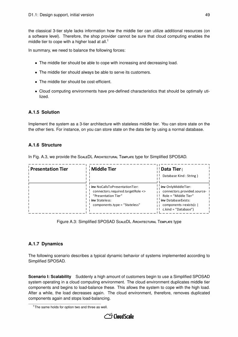
D1.1: Design support, initial version 49
the classical 3-tier style lacks information how the middle tier can utilize additional resources (ona software level). Therefore, the shop provider cannot be sure that cloud computing enables themiddle tier to cope with a higher load at all.1
In summary, we need to balance the following forces:
• The middle tier should be able to cope with increasing and decreasing load.
• The middle tier should always be able to serve its customers.
• The middle tier should be cost-efficient.
• Cloud computing environments have pre-defined characteristics that should be optimally uti-lized.
A.1.5 Solution
Implement the system as a 3-tier architecture with stateless middle tier. You can store state on thethe other tiers. For instance, on you can store state on the data tier by using a normal database.
A.1.6 Structure
In Fig. A.3, we provide the ScaleDL Architectural Template type for Simplified SPOSAD.
Presentation Tier
inv NoCallsToPresentationTier: connectors.required.targetRole <> “Presentation Tier“inv Stateless: components.type = “Stateless“
Middle Tier
inv OnlyMiddleTier: connectors.provided.source- Role = “Middle Tier“inv DatabaseExists: components->exists(c | c.kind = “Database“)
Data Tier (
Database Kind : String )
Figure A.3: Simplified SPOSAD ScaleDL Architectural Template type
A.1.7 Dynamics
The following scenario describes a typical dynamic behavior of systems implemented according toSimplified SPOSAD.
Scenario I: Scalability Suddenly a high amount of customers begin to use a Simplified SPOSADsystem operating in a cloud computing environment. The cloud environment duplicates middle tiercomponents and begins to load-balance these. This allows the system to cope with the high load.After a while, the load decreases again. The cloud environment, therefore, removes duplicatedcomponents again and stops load-balancing.
1The same holds for option two and three as well.

D1.1: Design support, initial version 50
A.1.8 Implementation
For implementing stateless middle tier components, component architectures like EJB have a dedi-cated support. For example, EJB allows to annotate components (sessions beans) by means of the@Stateless annotation.
A.1.9 Example Resolved
Note that Simplified SPOSAD does not only describe SaaS applications. It also relates to PaaSenvironments that host SaaS applications. For example, the database can be a PaaS service that isused by the data tier of the SaaS application.
A.1.10 Variants
In Sec. A.2, we describe a the SPOSAD ScaleDL Architectural Template, i.e., a SPOSAD version wedid not simplify.
A.1.11 Known Uses
Throughout Chap. 6, we use Simplified SPOSAD as a running example for ScaleDL ArchitecturalTemplates.
A.1.12 Consequences
We identified the following benefits for Simplified SPOSAD:
• The system becomes scalable by design.
We are aware of the following liabilities for Simplified SPOSAD:
• The middle tier becomes highly restricted because it forbids statefull components. Therefore,legacy systems may have problems to conform to Simplified SPOSAD.
A.1.13 See Also
Simplified SPOSAD includes the 3-tier architecture and Pipes-and-Filters architectural styles (forusing load-balancers on the middle tier).
A.2 SPOSAD ScaleDL Architectural Template
The SPOSAD architectural style [Koz11] provides a structure for SaaS applications that are (1) ableto serve multiple tenants and (2) are scalable. SPOSAD is based on a 3-tier architecture withpresentation, middle, and data tier.

D1.1: Design support, initial version 51
For scalability, SPOSAD requires presentation and application logic components to be stateless,thus, allowing a PaaS to clone these components and to use load balancers for providing access tothem. State is either stored at a tenant’s browser (cookies) or in the database component. Data isexchanged either synchronously via REST [FT00] or asynchronously. Application logic accesses thedatabase synchronously for short queries (specified by a timeout) and asynchronously otherwise.
For multi-tenancy, SPOSAD requires (1) a multi-tenant database, for example, by using distributeddatabases [Koz11], and (2) a metadata manager in the middle tier that queries tenant-specific datafrom the database. Tenants transmit their tenant IDs via REST to the metadata manager. Tenant-specific data can be used for customized UI and application logic.
A.2.1 Also Known As
Shared, Polymorphic, Scalable Application, and Data (SPOSAD)
A.2.2 Example
SPOSAD targets Web applications that should provide multi-tenancy and/or be scalable. Therefore,the example of Sec. 6.1 is a typical scenario for using SPOSAD (like we argued in Sec. 6.1). Forthis scenario, Fig. A.4 shows an instantiation of a SPOSAD ScaleDL Architectural Template.
Note that this instantiation extends the simplified SPOSAD instantiation of Sec. 6.1. For instance,the middle tier is now subdivided into "Application Logic" and "Metadata Management" roles that putSPOSAD’s additional constraints on the middle tier area. Our example in Sec. 6.1 abstracts fromSPOSAD’s capability to serve multiple tenants, however, the descriptions of the latter section alsohold here.
A.2.3 Context
A 3-tier architecture that requires multi-tenancy and/or scalability.
A.2.4 Problem
Assume a classical 3-tier system that has to cope with increasing or spiking load scenarios. Forinstance, a book shop implemented via a classical 3-tier architecture may face a suddenly increasingload before Christmas. When additionally requiring that the shop needs to find customer-specificdata, the situation gets even more complicated.
To cope with high load, the shop could simply reject incoming requests. However, this is problematicas the shop provider potentially looses the opportunity to make profit from additional customers.
As a second option, the shop provider could over-provision the book shop such that the shop cancope with unexpected high load scenarios. However, in times with lower load, the provider has topay additional money for maintaining the shops’ infrastructure while making less profit because offewer customers.
A third option for the provider is to add additional hardware resources once observing load peaks andremoving it again when load decreases. For this approach, the provider has to setup and maintainadditional resources. This setup may take too long such that the high load situation could already

D1.1: Design support, initial version 52
inv REST: components.provided.type = “REST“inv Stateless: components.type = “Stateless“
Presentation Tier
inv NoCallsToPresentationTier: connectors.required.targetRole <> “Presentation Tier“
Middle Tier
inv REST: components.provided.type = “REST“inv OnlyMiddleTier: connectors.provided.source- Role = “Middle Tier“inv DatabaseExists: components->exists(c | c.kind = “Database“)
Data Tier (
Database Kind = NoSQL )
inv Stateless: components.type = “Stateless“inv ShortSyncCallsToDB: connectors.required.timeout = true
Application Logic
inv REST: components.provided.type = “REST“
Metadata Management
Book Management
BookDatabase
Metadata Manager
Book Shop FrontendTenant1
Tenant2
Figure A.4: Example ScaleDL Architectural Template instantiation for SPOSAD
be over (and customers are unsatisfied). Removing hardware resources after high load situationsrequires additional effort and costs.
To cope with the latter disadvantages, a fourth option is to move the whole book shop to a cloudcomputing environment. This environment could then take care of automatically and effectivelyadding and removing resources on demand.
While cloud computing environments can cope with the before-mentioned disadvantages, they stilldo not guarantee that the book shop will actually scale. The reason for this lack is that the classical3-tier style does not provide information how additional resources can be utilized (on a softwarelevel). Similarly, the 3-tier style provides no guidance for designing a scalable book shop for multipletenants. Therefore, the shop provider cannot be sure that cloud computing enables the shop to copewith a higher load at all.2
In summary, we need to balance the following forces:
• The system should be able to cope with increasing and decreasing load.
• The system should always be able to serve its customers.
• The system should be cost-efficient.
• The system can serve multiple tenants.
• Cloud computing environments have pre-defined characteristics that should be optimally uti-lized.
2The same holds for option two and three as well.

D1.1: Design support, initial version 53
A.2.5 Solution
Implement the system as a 3-tier architecture with stateless middle tier. You can store state on theclient site by follow the REST architectural style. You can store state on the data tier by using anormal database.
However, this database should have dedicated support for multi-tenancy based on tenant IDs. Ten-ants transmit their IDs via REST to the middle tier. On this tier, a metadata manager is responsibleto customize the middle tier to the tenants’ needs as well as to store and receive tenant-specific datafrom the database.
A.2.6 Structure
In Fig. A.5, we provide the ScaleDL Architectural Template type for SPOSAD.
inv REST: components.provided.type = “REST“inv Stateless: components.type = “Stateless“
Presentation Tier
inv NoCallsToPresentationTier: connectors.required.targetRole <> “Presentation Tier“
Middle Tier
inv REST: components.provided.type = “REST“inv OnlyMiddleTier: connectors.provided.source- Role = “Middle Tier“inv DatabaseExists: components->exists(c | c.kind = “Database“)
Data Tier (
Database Kind : String )
inv Stateless: components.type = “Stateless“inv ShortSyncCallsToDB: connectors.required.timeout = true
Application Logic
inv REST: components.provided.type = “REST“
Metadata Management
Figure A.5: SPOSAD ScaleDL Architectural Template type
A.2.7 Dynamics
The following scenarios describe typical dynamic behaviors of systems implemented according toSPOSAD.
Scenario I: Multi-Tenancy A tenant issues an initial request to the presentation tier by passingits tenant ID. The presentation tier contacts the metadata manager to receive a tenant name for atenant-specific login screen. For this customization, the presentation tier passes the tenant ID tothe metadata manager. The metadata manager contacts the database on the data tier to query thetenant name based on the given tenant ID. Subsequently, the metadata manager returns the tenantname as a result to the presentation tier. The presentation tier then shows the tenant name on thelogin screen.
D1.1: Design support, initial version 54
Scenario II: Scalability Suddenly a high amount of tenants begin to use a SPOSAD system oper-ating in a cloud computing environment. The cloud environment duplicates application logic compo-nents and begins to load-balance these. This allows the system to cope with the high load. After awhile, the load decreases again. The cloud environment, therefore, removes duplicated componentsagain and stops load-balancing.
A.2.8 Implementation
For realizing the REST style, using HTTP should be used.
A.2.9 Example Resolved
Note that SPOSAD does not only describe SaaS applications. It also relates to PaaS environmentsthat host SaaS applications. For example, the database can be a PaaS service that is used by thedata tier of the SaaS application.
A.2.10 Variants
In Sec. A.1, we describe a simplified SPOSAD ScaleDL Architectural Template.
A.2.11 Known Uses
Several PaaS can be described in terms of SPOSAD: Force.com, Windows Azure, Google AppEngine, and SAP HANA Cloud.
A.2.12 Consequences
We identified the following benefits for SPOSAD:
• The system becomes scalable by design.
• The system can serve multiple tenants by design.
We are aware of the following liabilities for SPOSAD:
• The middle tier becomes highly restricted because it forbids statefull components. Therefore,legacy systems may have problems to conform to SPOSAD.
• Handling multiple tenants increases system complexity.
A.2.13 See Also
SPOSAD includes the 3-tier architecture, REST, and Pipes-and-Filters architectural styles.

D1.1: Design support, initial version 55
B Glossary
A glossary specifying key CloudScale terms is a live document [Clo13]. A snap shot of the glossaryis for completeness also included here.
Actor "An actor specifies a role played by a user or any other system that interacts with the sub-ject." [Obj11]
Architectural Styles Architectural styles are Conceptual solution structures applied continuouslyand widely without exceptions on one element of an architecture (based on [BBJ+08]). Exam-ples are the 3-Tier style, Pipes&Filters, and SPOSAD.
Architectural Templates The Architectural Template (AT) language is a language to formalize ar-chitectural styles on component models. In particular, this formalization allows to enrich stylesby quality annotations and completions for model-driven quality analyses. Quality annotationscharacterize a concrete quality property of interest. Quality completions utilize these annota-tions to derive quality models that can be used as input to quality analysis tools. The languageis formalized as "ScaleDL Architectural Template".
Whenever we refer to "an Architectural Template (AT)", we talk about a concrete architecturalstyle formalized by the AT language. Accordingly, the plural form, Architectural Templates(ATs), refers to a set of these formalizations.
CloudScale Architectural Templates CloudScale Architectural Templates (CATs) are the set ofarchitectural templates (ATs) we evaluated for CloudScale. This set of ATs (1) representingbest practices for designing SaaS applications and (2) allows to analyse the scalability of SaaSapplications.
CloudScale Environment CloudScale’s Eclipse application. It is a front end to all CloudScale tools.
Costs Costs are the valuated consumption of resources necessary to provide a certain service (pertime unit). (Our definition is based on two German statements: "Kosten bezeichnen in derRegel den mit Marktpreisen bewerteten Einsatz von Produktionsfaktoren bei der Herstellungvon Gütern und Dienstleistungen" [Wik13, Kosten] and "Kosten stehen betriebswirtschaftlichgesehen für den bewerteten Verbrauch an Produktionsfaktoren in Geldeinheiten (GE), welchezur Erstellung der betrieblichen Leistung in einer Abrechnungsperiode notwendig sind" [Wik13,Kosten].) Typically, this valuation is monetary. Also see economic costs [Wik13, Economiccost] and operating cost [Wik13, Operating cost].
Customer An actor consuming services of a service provider. The term "service customer" cansynonymously be used. Refinements of a "service customer" include "SaaS customer", "PaaScustomer", and "IaaS customer". Other typical synonyms are "user" and "consumer", however,these synonyms should be avoided for clarity.
Deployer An actor making a layer’s services ready to use, potentially by releasing a software sys-tem on top of lower-layer services. The term "service deployer" can synonymously be used.Refinements of a "service deployer" include "SaaS deployer", "PaaS deployer", and "IaaSdeployer".
Dynamic Spotter The Dynamic Spotter is a performance problem diagnosis that finds scalabilityissues in code by measurements.

D1.1: Design support, initial version 56
Elasticity For an as-a-Service layer, elasticity is the degree to which the layer is able to adaptto workload changes by (de)provisioning services of its underlying layers in an autonomicmanner such that at each point in time the utilised services fulfil the SLOs of the layer asclosely as possible. (based on [HKR13])
Load Load is the characterisation of the quantity of customer’s service requests at a given time,e.g., by characterising the request rate.
Metric A metric is a "precisely defined method which is used to associate an element of an (ordered)set V to a system S" [EFR08]. Typically, we use metrics to determine a quantity (V is the setof natural or real numbers). An example SaaS quantity metric is the sum of consumed IaaSand PaaS services. Example IaaS quantity metrics include the number of consumed CPUservices as well as the number of CPU, disk and network invocations by customers.
Ontology "In computer science and information science, an ontology formally represents knowl-edge as a set of concepts within a domain, and the relationships between pairs of concepts. Itcan be used to model a domain and support reasoning about concepts." [Wik13, InformationScience] We use directed graphs to represent ontologies where nodes represent conceptsand edges represent relationships. An example for reasoning is the identification of transitiverelationships. Nodes can represent types as well as instances. "OWL is a language for makingontological statements, developed as a follow-on from RDF and RDFS" [Wik13, InformationScience]. Furthermore, OWL ontologies can be queried by SPARQL. The most popular OWLreasoner is Pellet.
PCM The Palladio Component Model (PCM) is a component-based architecture description lan-guage, with a focus on performance properties (response time, throughput, utilization).
Performance For an as-a-Service layer, the performance for a given workload is measured in termsof a quality metric.
Price The price is the valuation for a quantity of a certain service, typically realised in monetaryunits. (Based on the following German statement: "Der Preis [..] ist der üblicherweise inGeldeinheiten realisierte Wert eines Gutes oder einer Dienstleistung." [Wik13, Preis (Wirkschaft)])
Price Model A price model is the concrete specification of prices for consuming services. Forexample, the service provider Amazon provides its price model for the EC2 IaaS solution onits web page [Ama]. A typical synonym is "cost model", however, this synonym should beavoided as we want to strictly distinguish between costs and prices.
Product Manager Product manager is a final decision maker for the solution and negotiation withcustomer about service/system acceptance and approval of system evolution during the run-time phase. Main interests of the product manager include overall system behaviour, architec-ture compliance, and price of the final solution.
Provider An actor offering services. The term "service provider" can synonymously be used.Refinements of a "service provider" include "SaaS provider", "PaaS provider", and "IaaSprovider".
Quantity a property that can exist as a magnitude or multitude." [Wik13, Quantity]
Quality metric defines a standard of measurement for a quality characteristic. A quality metric isan essential part of a Service Level Agreement (SLA). External metrics for the quality char-acteristics of [ISO01] are defined in [ISO03]. Examples of metrics for the time behavioursub-characteristic of (performance) efficiency include response time (measured in terms oftime) and throughput (measured in terms of count/time). A more complex metric used in tele-com is Mean Opinion Score (MOS). The MOS is a number between one (bad) and five (best),

D1.1: Design support, initial version 57
representing quality of experience. Quality metrics may also reflect system properties likeutilisation of some hardware resources.
Quality threshold is the border between acceptable and non acceptable quality, when applying aquality metric. With under-provisioning, the quality crosses this border, and we get an SLAviolation. With over-provisioning, the quality is better than the threshold. As an examplewhere the quality metric is response time, the threshold may be 1 second, meaning that usersare satisfied with less than 1 second response time. More than one second will be an SLAviolation. On the other hand, less than 1 second means that we have over-provisioning.
Part of the quality threshold specification must also be an agreement on how this quality shallactually be measured. In the case of response time, the threshold can, e.g., be the same forall service invocations, only apply to the 90 percentile, or only for the average.
Resource In computer science, a "resource, or system resource, is any physical or virtual com-ponent of limited availability within a computer system." [Wik13, Computer science] In eco-nomics, resources (or ’factors of production’) "are the inputs to the production process." [Wik13,Resource (economics)] Furthermore, resources "are any commodities or services used to pro-duce goods or services" [Wik13, Resource (economics)], which provides a link between thecomputer science and the economic definition.
Scalability For an as-a-Service layer, scalability is the ability of the layer to sustain changing work-loads while fulfilling its SLA, potentially by consuming a higher/lower quantity of lower layerservices. (based on [HKR13])
For the SaaS layer, scalability is the ability of the software to sustain changing workloads whilefulfilling its SLA, potentially by consuming a higher/lower quantity of PaaS or IaaS services.
Scalability Analyst Scalability analyst is an actor who is monitoring the scalability of the system.Based on the analysis, scalability analyst can detect scalability issues potentially resulting withsystem evolution.
ScaleDL The Scalability Description Language (ScaleDL) is a language to characterize cloud-based systems, with a focus on scalability properties. ScaleDL includes three sublanguages:ScaleDL Usage Evolution, ScaleDL Architectural Template, and ScaleDL Overview.
ScaleDL Architectural Template is the formalization of the Architectural Template (AT) language.ScaleDL Architectural Template is realized via an EMF metamodel. Its syntax and semanticsare described in deliverable D1.1.
ScaleDL Overview is a formalization of the deployment and architectural decisions language. Itssyntax and semantics are described in deliverable D3.1.
ScaleDL Usage Evolution is the formalization of the usage evolution language. ScaleDL UsageEvolution is realized via an EMF metamodel. Its syntax and semantics are described in deliv-erable D1.1.
Service Software deployed by the deployer, i.e., software running on a layer waiting for requests (byservice customers) to be executed. Typically, this execution is charged by service providers.Because services can be consumed by service customers, they are a special kind of a re-source. The term "software service" can synonymously be used.
Service Description The characterization of a service, e.g., by operation interfaces, their protocols,or by an SLA.
D1.1: Design support, initial version 58
SLA "A service-level agreement (SLA) is a contractual agreement outlining a specific service com-mitment made between contract parties – a service provider and its customer. The SLA in-cludes language describing the overall service, financial aspects of service delivery, includ-ing fees, penalties, bonuses, contract terms and conditions, and specific performance met-rics governing compliant service delivery. These individual performance metrics are calledservice-level objectives (SLOs)." [Sea]
SLO Service-level objectives (SLOs) are "[...] performance metrics governing compliant servicedelivery. [...] Each SLO corresponds with a single performance characteristic relevant to thedelivery of an overall service. Some examples of SLOs would include: system availability, helpdesk incident resolution time and application response time." [Sea]
Spotter With spotter, we refer to both, the static or the dynamic spotter.
Stakeholders Stakeholders are actors who have roles associated that are specific for a concreteas-a-Service (XaaS) layer. Typical XaaS stakeholders are XaaS customers, XaaS providers,XaaS architects, XaaS developers, XaaS deployers, and XaaS maintainers.
Static Spotter The Static Spotter is a static code and model analysis that finds scalability issues byanalyzing code and/or system models.
System Engineer System engineer is an actor responsible for the runtime system monitoring pro-cess and identification of the system critical elements. This actor also drives the systemevolution phase.
Usage Evolution A description of how the workload and the quality thresholds of a service evolves.Described in more detail in D1.1.
Work Work is the characterisation of the data to be processed by a certain layer.
Workload Workload is the combined characterisation of work and load.

D1.1: Design support, initial version 59
Bibliography
[Ama] Amazon. Amazon EC2 Pricing. http://aws.amazon.com/ec2/pricing. Last visited:26 September 2013.
[Amd67] Gene M. Amdahl. Validity of the single processor approach to achieving large scalecomputing capabilities. In AFIPS, pages 483 – 485. AFIPS Press, 1967.
[BBJ+08] Achim Baier, Steffen Becker, Martin Jung, Klaus Krogmann, Carsten Ruttgers, NielsStreekmann, Karsten Thoms, and Steffen Zschaler. Handbuch der Software-Architektur.dPunkt.verlag Heidelberg, 2 edition, December 2008.
[BBM13] Matthias Becker, Steffen Becker, and Joachim Meyer. SimuLizar: design-time modellingand performance analysis of self-adaptive systems. In Proceedings of Software Engi-neering 2013 (SE2013), Aachen, 2013.
[BCK13] Len Bass, Paul Clements, and Rick Kazman. Software Architecture in Practice. AddisonWesley, 3rd edition, 2013.
[BHFL04] Gunnar Brataas, Peter H. Hughes, John-Arne Fagerli, and Odd Christian Landmark.Exploring Architectural Scalability. Software Engineering Notes, 29(1):125 – 129, 2004.
[BKR09] Steffen Becker, Heiko Koziolek, and Ralf Reussner. The palladio component model formodel-driven performance prediction. Journal of Systems and Software, 82(1):3–22,January 2009.
[BL10] Paul Brebner and Anna Liu. Modeling cloud cost and performance. In Annual Interna-tional Conference on Cloud Computing and Virtualization (CCV 2010), pages 79 – 86.CCV 2010 & GSTF, 2010.
[BLB12] Matthias Becker, Markus Luckey, and Steffen Becker. Model-driven performance engi-neering of self-adaptive systems: a survey. In Proceedings of the 8th international ACMSIGSOFT conference on Quality of Software Architectures, QoSA ’12, pages 117–122,New York, NY, USA, 2012. ACM.
[BMR+96] Frank Buschmann, Regine Meunier, Hans Rohnert, Peter Sommerlad, Michael Stal, andMichael Stal. Pattern-Oriented Software Architecture Volume 1: A System of Patterns.Wiley, volume 1 edition, August 1996. Published: Hardcover.
[BSL+13] Gunnar Brataas, Erlend Stav, Sebastian Lehrig, Steffen Becker, Goran Kopc̆ak, andDarko Huljenic. CloudScale: Scalability Management for Cloud Systems. In Interna-tional Conference on Performance Engineering (ICPE), Proceedings of. ACM, 2013.
[Clo13] CloudScale. Glossary. http://cloudscale.xlab.si/wiki/index.php/Glossary, 2013. Inspected7 October 2013.
[Cou02] Transaction P. Council. TPC-W benchmark (web commerce) specification version 1.8.http://www.tpc.org/tpcw/spec/tpcw_V1.8.pdf, February 2002. Last visited: 15April 2013.
[DLR13] Leticia Duboc, Emmanuel Letier, and David Rosenblum. Systematic Elaboration of Scal-ability Requirements through Goal-Obstacle Analysis. Transactions on Software Engi-neering, 39(1):119 – 140, 2013.

D1.1: Design support, initial version 60
[EFR08] Irene Eusgeld, Felix C. Freiling, and Ralf Reussner, editors. Dependability Metrics: Ad-vanced Lectures [result from a Dagstuhl seminar, October 30 - November 1, 2005], vol-ume 4909 of LNCS. Springer, 2008.
[EPM13] T. Erl, R. Puttini, and Z. Mahmood. Cloud Computing: Concepts, Technology and Design.Prentice Hall PTR, 2013.
[FT00] R T Fielding and R N Taylor. Principled design of the modern web architecture, 2000.
[Gun07] Neil J. Gunther. Guerrilla Capacity Planning. Springer, 2007.
[Gus88] J.L. Gustafsson. Re-evaluating Amdahl’s Law. CACM, 31(5):532 – 533, 1988.
[HFBR08] Jens Happe, Holger Friedrich, Steffen Becker, and Ralf H. Reussner. A Pattern-BasedPerformance Completion for Message-Oriented Middleware. In Proceedings of the 7thinternational workshop on Software and performance, WOSP ’08, pages 165–176, NewYork, NY, USA, 2008. ACM.
[HKR13] Nikolas Roman Herbst, Samuel Kounev, and Ralf Reussner. Elasticity in cloud comput-ing: What it is and what it is not. In Proceedings of the 10th International Conference onAutonomic Computing (ICAC 2013). USENIX, 2013.
[HL07] Peter Henry Hughes and Jakob Sverre Løvstad. A Generic Model for Quantifiable Soft-ware Deployment. In Software Engineering Advances. IEEE, 2007.
[ISO01] ISO/IEC Standard. Software Engineering – Product Quality – Part 1: Quality Model.ISO/IEC Standard 9126-1, ISO/IEC, 2001.
[ISO03] ISO/IEC Standard. Software Engineering – Product Quality – Part 2: External metrics.ISO/IEC Standard 9126-2, ISO/IEC, 2003.
[ISO11] ISO/IEC Standard. Systems and software engineering – Systems and software QualityRequirements and Evaluation (SQuaRE) – System and software quality models. ISO/IECStandard 25010, ISO/IEC, 2011.
[Ive10] Villy B. Iversen. Teletraffic Engineering and Network Planning. Technical University ofDenmark, 2010.
[JW00] Prasad Jogalekar and Murray Woodside. Evaluating the Scalability of Distributed Sys-tems. Transactions on Parallel and Distributed Systems, 11(6):589 – 603, 2000.
[KKL10] Donald Kossmann, Tim Kraska, and Simon Loesing. An evaluation of alternative ar-chitectures for transaction processing in the cloud. In Proceedings of the 2010 ACMSIGMOD International Conference on Management of data, SIGMOD ’10, pages 579 –590, New York, NY, USA, 2010. ACM.
[Koz11] Heiko Koziolek. The SPOSAD architectural style for multi-tenant software applications.In Proc. 9th Working IEEE/IFIP Conf. on Software Architecture (WICSA’11), Workshopon Architecting Cloud Computing Applications and Systems, pages 320–327. IEEE, July2011.
[Mea13] Aleksaner Milenhoski and et al. Cloud Usage Patterns: A Formalisation for Descriptionof Cloud Usage Scenarios. Technical Report SPEC-RG-20013-001, Version 1.0, SPEC,April 2013.
[MOD13] MODAClouds. MOdel-Driven Approach for design and execution of applications on mul-tiple Clouds. http://www.modaclouds.eu/, 2013. Inspected 15 October 2013.
D1.1: Design support, initial version 61
[MUS10] MUSIC. Context-aware self-adaptive platform for mobile applications. http://ist-music.berlios.de/site/, 2010. Inspected 2 July 2013.
[Obj11] Object Management Group (OMG). OMG Unified Modeling Language (OMG UML), Su-perstructure Specification (Version 2.4.1). Technical Report OMG Document Number:formal/2011-08-06, Object Management Group, August 2011.
[OMG11] OMG. UML Profile for MARTE. http://www.omg.org/spec/MARTE/, June 2011. Version1.1, Inspected 2 July 2013.
[RWL96] Trygve Reenskaug, Per Wold, and Odd Arild Lehne. Working with objects - the OOramsoftware engineering method. Manning, 1996.
[Sea] SearchCIO. What is the difference between SLO and SLA? http://searchcio.techtarget.com/answer/Whats-the-difference-between-SLO-and-SLA. Last vis-ited: 26 September 2013.
[SLA13] SLA@SOI. The SLA* Model. http://sla-at-soi.sourceforge.net/sla-model-y3/, 2013. In-spected 24 August 2013.
[vDL13] Markus von Detten and Sebastian Lehrig. Reengineering of component-based soft-ware systems in the presence of design deficiencies - an overview. In 15th WorkshopSoftware-Reengineering (WSR’13), Bad Honnef, Germany, May 2013.
[WHH13] Alexander Wert, Jens Happe, and Lucia Happe. Supporting swift reaction: automati-cally uncovering performance problems by systematic experiments. In Proceedings ofthe 2013 International Conference on Software Engineering, ICSE ’13, pages 552–561.IEEE, 2013.
[Wik13] Wikipedia, German and English. www.wikipedia.org, 2013. Inspected 5 August 2013.