schematic and pcb print 24 datasheet 24 software 24 ... · the si5351 clock generator is an i2c...
TRANSCRIPT

Adafruit Si5351 Clock Generator BreakoutCreated by lady ada
Last updated on 2017-06-02 07:54:50 PM UTC

23667
99
1011
131313141617171718
18181924242424
Guide Contents
Guide ContentsOverviewPinouts
Power PinsI2C Pins
AssemblyPrepare the header strip:Add the breakout board:And Solder!
Wiring & TestWiring for ArduinoDownload Adafruit_Si5351Load Demo SketchLibrary ReferenceBegin!Set up the PLL
Set up the PLL with 'integer mode'Set up the PLL with 'fractional mode'
Set up the clock dividerAdditional R DividerSoftwareDownloadsSoftwareDatasheetSchematic and PCB Print
© Adafruit Industries https://learn.adafruit.com/adafruit-si5351-clock-generator-breakout Page 2 of 25
Overview
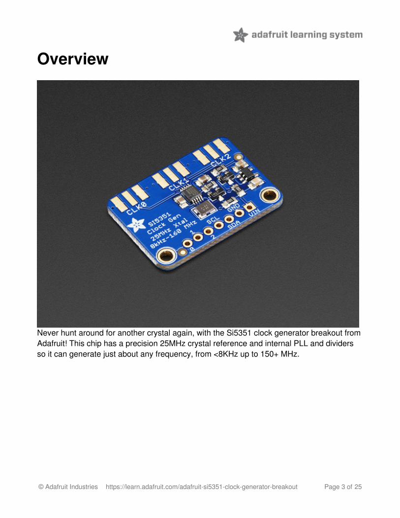
Never hunt around for another crystal again, with the Si5351 clock generator breakout fromAdafruit! This chip has a precision 25MHz crystal reference and internal PLL and dividersso it can generate just about any frequency, from <8KHz up to 150+ MHz.
© Adafruit Industries https://learn.adafruit.com/adafruit-si5351-clock-generator-breakout Page 3 of 25
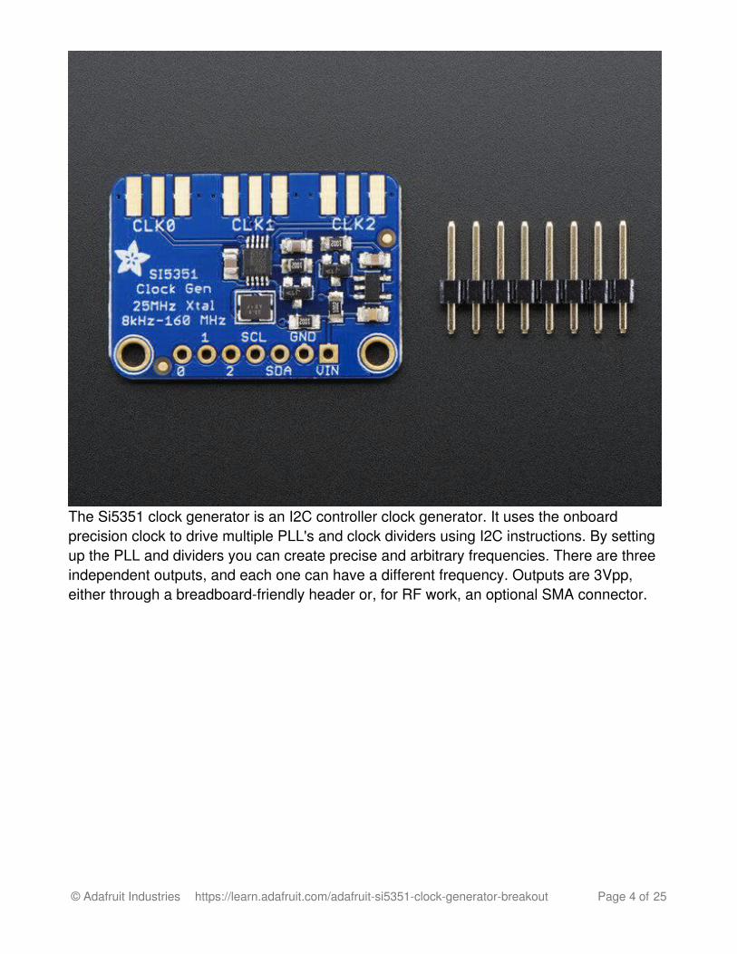
The Si5351 clock generator is an I2C controller clock generator. It uses the onboardprecision clock to drive multiple PLL's and clock dividers using I2C instructions. By settingup the PLL and dividers you can create precise and arbitrary frequencies. There are threeindependent outputs, and each one can have a different frequency. Outputs are 3Vpp,either through a breadboard-friendly header or, for RF work, an optional SMA connector.
© Adafruit Industries https://learn.adafruit.com/adafruit-si5351-clock-generator-breakout Page 4 of 25
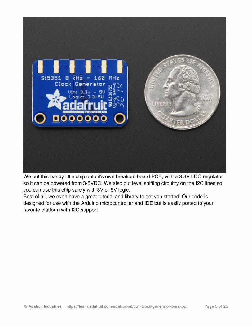
We put this handy little chip onto it's own breakout board PCB, with a 3.3V LDO regulatorso it can be powered from 3-5VDC. We also put level shifting circuitry on the I2C lines soyou can use this chip safely with 3V or 5V logic.Best of all, we even have a great tutorial and library to get you started! Our code isdesigned for use with the Arduino microcontroller and IDE but is easily ported to yourfavorite platform with I2C support
© Adafruit Industries https://learn.adafruit.com/adafruit-si5351-clock-generator-breakout Page 5 of 25
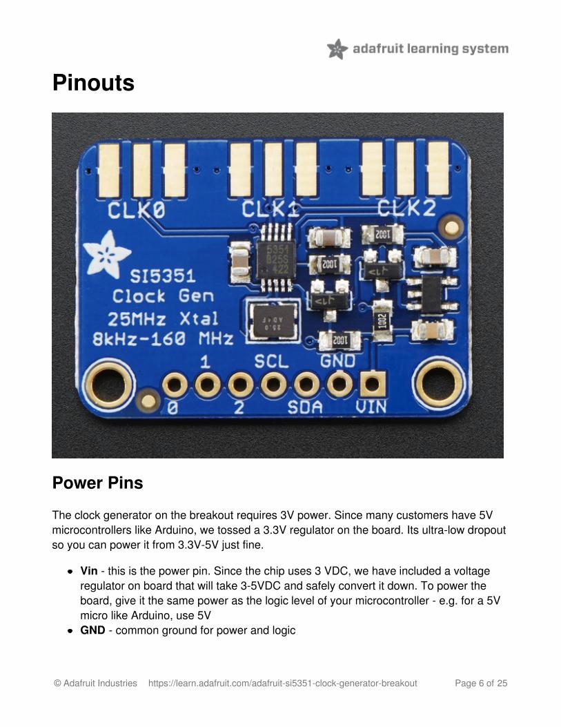
Pinouts
Power Pins
The clock generator on the breakout requires 3V power. Since many customers have 5Vmicrocontrollers like Arduino, we tossed a 3.3V regulator on the board. Its ultra-low dropoutso you can power it from 3.3V-5V just fine.
Vin - this is the power pin. Since the chip uses 3 VDC, we have included a voltageregulator on board that will take 3-5VDC and safely convert it down. To power theboard, give it the same power as the logic level of your microcontroller - e.g. for a 5Vmicro like Arduino, use 5VGND - common ground for power and logic
© Adafruit Industries https://learn.adafruit.com/adafruit-si5351-clock-generator-breakout Page 6 of 25

I2C Pins
SCL - I2C clock pin, connect to your microcontrollers I2C clock line. This pin is levelshifted so you can use 3-5V logic, and there's a 10K pullup on this pin.SDA - I2C data pin, connect to your microcontrollers I2C data line. This pin is levelshifted so you can use 3-5V logic, and there's a 10K pullup on this pin.
Clock Out Pins
0, 1, and 2 - These are the 3 independent clock generated outputs. They are squarewaves, from 0-3V.
The clock out pins are also brought out to SMA edge-launch connectors on the other sideof the PCB. You can purchase and solder on some edge-launch SMAconnectors (http://adafru.it/dPr) if you want to pipe the signal into an RF cable.
© Adafruit Industries https://learn.adafruit.com/adafruit-si5351-clock-generator-breakout Page 7 of 25

© Adafruit Industries https://learn.adafruit.com/adafruit-si5351-clock-generator-breakout Page 8 of 25

Assembly
If you have the breadboard version of this sensor, you'll want to solder some header ontothe sensor so it can be used in a breadboard.
Prepare the header
© Adafruit Industries https://learn.adafruit.com/adafruit-si5351-clock-generator-breakout Page 9 of 25

strip:
Cut the strip to length ifnecessary. It will be easier tosolder if you insert it into abreadboard - long pins down
Add the breakoutboard:
Place the breakout board overthe pins so that the short pinspoke through the breakout pads
© Adafruit Industries https://learn.adafruit.com/adafruit-si5351-clock-generator-breakout Page 10 of 25

And Solder!
Be sure to solder all pins forreliable electrical contact.
Solder the longer power/datastrip first
(For tips on soldering, be sure tocheck out our Guide to ExcellentSoldering (http://adafru.it/aTk)).
© Adafruit Industries https://learn.adafruit.com/adafruit-si5351-clock-generator-breakout Page 11 of 25

You're done! Check your solderjoints visually and continue ontothe next steps
© Adafruit Industries https://learn.adafruit.com/adafruit-si5351-clock-generator-breakout Page 12 of 25
Wiring & Test
Wiring for ArduinoYou can easily wire this breakout to any microcontroller, we'll be using an Arduino. Foranother kind of microcontroller, just make sure it has I2C capability, then port the code - itspretty simple stuff!
(http://adafru.it/dPs)
(http://adafru.it/pBC)
Connect Vin to the power supply, 3-5V is fine. Use the same voltage that themicrocontroller logic is based off of. For most Arduinos, that is 5VConnect GND to common power/data groundConnect the SCL pin to the I2C clock SCL pin on your Arduino. On an UNO & '328based Arduino, this is also known as A5, on a Mega it is also known as digital 21 andon a Leonardo/Micro, digital 3Connect the SDA pin to the I2C data SDA pin on your Arduino. On an UNO & '328based Arduino, this is also known as A4, on a Mega it is also known as digital 20 andon a Leonardo/Micro, digital 2
Download Adafruit_Si5351To begin reading sensor data, you will need to download the Adafruit_Si5351 Library fromour github repository (http://adafru.it/dPu). You can do that by visiting the github repo andmanually downloading or, easier, just click this button to download the zipDownload the Adafruit Si5351 Libraryhttp://adafru.it/dPuRename the uncompressed folder Adafruit_Si5351 and check that the Adafruit_Si5351folder contains Adafruit_Si5351.cpp and Adafruit_Si5351.h
Place the Adafruit_Si5351 library folder your arduinosketchfolder/libraries/ folder. You may need to create the libraries subfolder if its your first library. Restart the IDE.
We also have a great tutorial on Arduino library installation at:http://learn.adafruit.com/adafruit-all-about-arduino-libraries-install-use (http://adafru.it/aYM)
© Adafruit Industries https://learn.adafruit.com/adafruit-si5351-clock-generator-breakout Page 13 of 25

Load Demo SketchNow you can open up File->Examples->Adafruit_Si5351->Si5351 and upload to yourArduino wired up to the sensor
Then open up the Serial console at 9600 baud to check the output. You should see thefollowing:
© Adafruit Industries https://learn.adafruit.com/adafruit-si5351-clock-generator-breakout Page 14 of 25
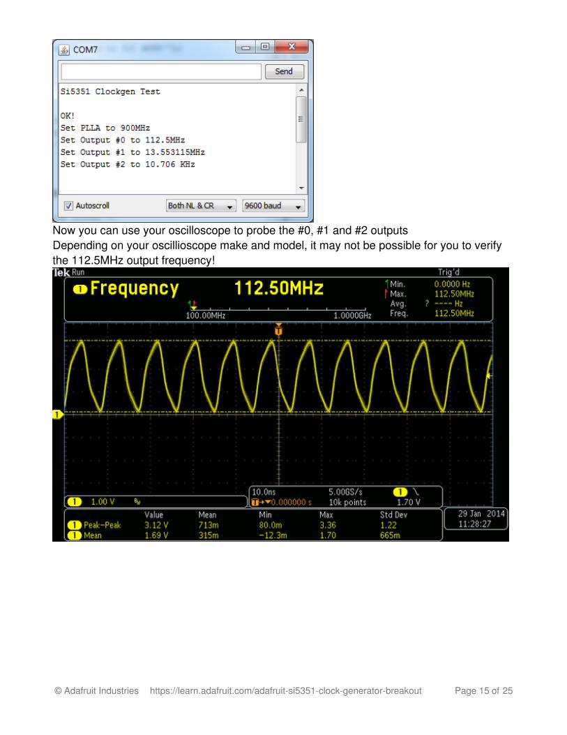
Now you can use your oscilloscope to probe the #0, #1 and #2 outputsDepending on your oscillioscope make and model, it may not be possible for you to verifythe 112.5MHz output frequency!
© Adafruit Industries https://learn.adafruit.com/adafruit-si5351-clock-generator-breakout Page 15 of 25

That's it! If you want to change the frequencies, adjust the example sketch and re-upload.
Library Reference
© Adafruit Industries https://learn.adafruit.com/adafruit-si5351-clock-generator-breakout Page 16 of 25

The library we have is simple and easy to use
You can create the Adafruit_Si5351 object with:
Adafruit_SI5351 clockgen = Adafruit_SI5351();
I2C does not have pins, as they are fixed in hardware.
Begin!To initialize the chip, call clockgen.begin() which will check that it can be found. Begin()returns true/false depending on these checks. We suggest you wrap begin() in a statementthat will check if the chip was located:
if (clockgen.begin() != ERROR_NONE) { /* There was a problem detecting the IC ... check your connections */ Serial.print("Ooops, no Si5351 detected ... Check your wiring or I2C ADDR!"); while(1); }
Set up the PLLThe chip uses two subsections to generate clock outputs. First it multiplies the 25MHzreference clock by some amount (setting up the PLL), then it divides that new clock bysome other amount (setting up the clock divider)
By noodling with the multiplier and divider you can generate just about any clock frequency!
There are two PLL multipliers (A and B), so if you want to have three outputs, two outputswill have to share one PLL.
Set up the PLL with 'integer mode'
The cleanest way to run the PLL is to do a straight up integer multiplication:
clockgen.setupPLLInt(SI5351_PLL_A or SI5351_PLL_B, m);
This sets PLL_A or PLL_B to be 25MHz * m and m (the integer multipler) can range from15 to 90!
© Adafruit Industries https://learn.adafruit.com/adafruit-si5351-clock-generator-breakout Page 17 of 25

Set up the PLL with 'fractional mode'
This mode allows a much more flexible PLL setting by using fractional multipliers for thePLL setup, however, the output may have a slight amount of jitter so if possible, try to useinteger mode!
clockgen.setupPLLInt(SI5351_PLL_A or SI5351_PLL_B, m, n, d);
This sets PLL_A or PLL_B to be 25MHz * (m + n/d)
m (the integer multipler) can range from 15 to 90n (the numerator) can range from 0 to 1,048,575d (the denominator) can range from 1 to 1,048,575
Set up the clock dividerOnce you have the PLLs set up, you can now divide that high frequency down to get thenumber you want for the output
Each output has its own divider. You can use the cleaner Integer-only divider:
clockgen.setupMultisynthInt(output, SI5351_PLL_x, SI5351_MULTISYNTH_DIV_x);
For the output use 0, 1 or 2For the PLL input, use either SI5351_PLL_A or SI5351_PLL_BFor the divider, you can divide by SI5351_MULTISYNTH_DIV_4,SI5351_MULTISYNTH_DIV_6, or SI5351_MULTISYNTH_DIV_8
Again, integer output will give you the cleanest clock. If you need more flexibility, use thefractional generator/divider:
clockgen.setupMultisynth(output, SI5351_PLL_x, div, n, d);
For the output use 0, 1 or 2For the PLL input, use either SI5351_PLL_A or SI5351_PLL_BThe final frequency is equal to the PLL / (div + n/d)div can range from 4 to 900n can range from 0 to 1,048,575d can range from 1 to 1,048,575
Additional R Divider
© Adafruit Industries https://learn.adafruit.com/adafruit-si5351-clock-generator-breakout Page 18 of 25
If you need to divide even more, to get to the < 100 KHz frequencies, there's an additionalR divider, that divides the output once more by a fixed number:
clockgen.setupRdiv(output, SI5351_R_DIV_x);
output is the clock output #The R divider can be any of the following:
SI5351_R_DIV_1SI5351_R_DIV_2SI5351_R_DIV_4SI5351_R_DIV_8SI5351_R_DIV_16SI5351_R_DIV_32SI5351_R_DIV_64SI5351_R_DIV_128
SoftwareAs you can see, the annoying part here is figuring out the best choice for PLL multipler ÷r! SiLabs has a desktop application called ClockBuilder (http://adafru.it/dPj) that cando some calculation of the PLL divider/multiplier for you. It's windows only, but you onlyneed to use it once for calculation.
Install and run, select the Si5351A with 3 outputs, and Do not connect to the EVB
© Adafruit Industries https://learn.adafruit.com/adafruit-si5351-clock-generator-breakout Page 19 of 25

Enable the output you want, and set the frequency as floating point or fraction
© Adafruit Industries https://learn.adafruit.com/adafruit-si5351-clock-generator-breakout Page 20 of 25
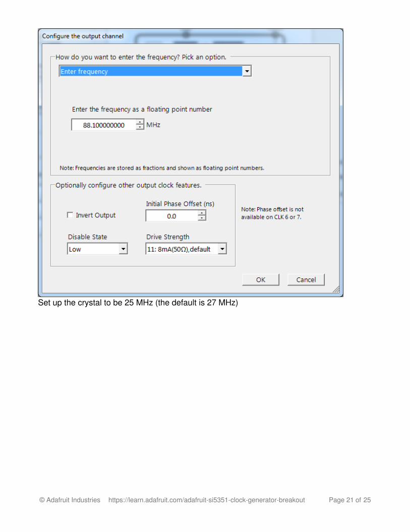
Set up the crystal to be 25 MHz (the default is 27 MHz)
© Adafruit Industries https://learn.adafruit.com/adafruit-si5351-clock-generator-breakout Page 21 of 25

Click on Create Frequency Plan to see the PLL and divider setups!
© Adafruit Industries https://learn.adafruit.com/adafruit-si5351-clock-generator-breakout Page 22 of 25

Earlier versions of this chip only take a divider of 900 or less, and our library doesn't let youselect > 900 for the integer div. So if you get a higher value from the calculator, you mayneed to adjust it!
© Adafruit Industries https://learn.adafruit.com/adafruit-si5351-clock-generator-breakout Page 23 of 25

Downloads
SoftwareSiLabs has a desktop application called ClockBuilder (http://adafru.it/dPj) that can do somecalculation of the PLL divider/multiplier for you.
DatasheetSi5351 Datasheet (http://adafru.it/dPk)Fritzing object in Adafruit Fritzing library (http://adafru.it/aP3)EagleCAD PCB files on GitHub (http://adafru.it/pBD)
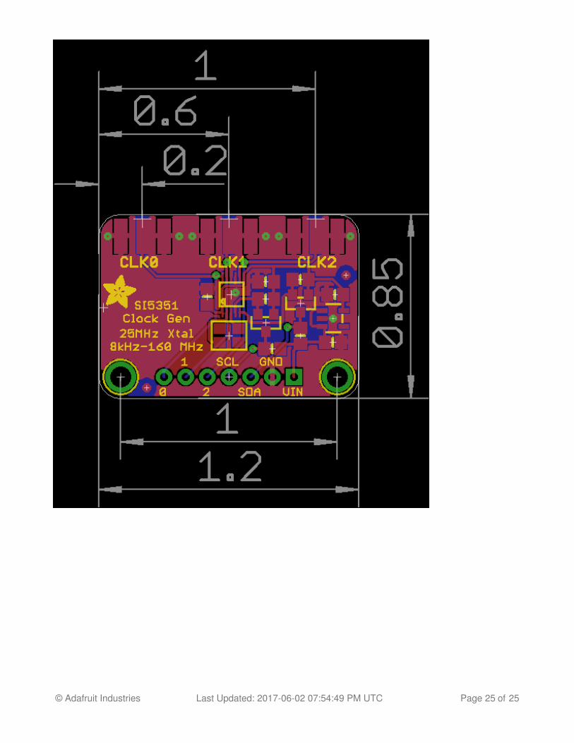
Schematic and PCB Print
© Adafruit Industries https://learn.adafruit.com/adafruit-si5351-clock-generator-breakout Page 24 of 25
© Adafruit Industries Last Updated: 2017-06-02 07:54:49 PM UTC Page 25 of 25