school of mechanical engineering department of automobile
TRANSCRIPT

SCHOOL OF MECHANICAL ENGINEERING
DEPARTMENT OF AUTOMOBILE ENGINEERING
SAU1404 VEHICLE DESIGN CHARACTERISTICS

UNIT I INTRODUCTION
Page1
UNIT-I INTRODUCTION
Heat Engines :- Heat engines is a device which transforms the
chemical energy of a fuel into thermal energy and uses this energy to
produce mechanical work. Heat engines are divided into two broad classes.
a) External combustion engines
b) Internal combustion engines.
In an external combustion engine the products of combustion of air and
fuel transfer heat to a second fluid which is the working fluid of the cycle,
as in the case of steam engine or a stem turbine plant where the heat of
combustion is employed to generate steam which is used in the piston
engine or turbine .Sterling engine is also an external combustion engine.
In an internal combustion engine the product of the combustion are
directly the motive fluid. Petrol, gas & diesel engines, Wankel engine, and
open cycle gas turbine are example of internal combustion engine. Jet
engine and rockets are also internal combustion engine.
The main advantages of internal combustion engines over external
combustion engines are greater mechanical simplicity, lower ratio of weight
and bulk to output due to absence of auxiliary apparatus like boiler and
condenser and hence lower first cost, higher overall efficiency, and lesser
requirement of water for dissipation of energy through cooling system.
Historical development.
Huygens Gunpowder Engine :- The earliest internal combustion can be
credited to famous Dutch physicist Christian Huygens (1629-1695) in the
year 1680. Huygens engine employing gunpowder.
Four Stroke Cycle :- All the engines developed uptil 1860 provided
combustion of the charge at about atmospheric pressure. In 1862, Beau de
Rochas, a Frenchmen, wrote a paper describing the fundamental principals
for efficient operation of piston combustion engine, which were
demonstrated in a practical engine by Otto, a German engineer. This laid
the foundation of four stroke cycle engine which is used till today in all
four stroke spark-ignition engines. This method of operation was explained
in the four operations as follows.

Page 2
1st Stroke :- Induction of charge during the outward stroke of piston.
2nd
Stroke :- Compression of the charge during inward stroke of the piston.
3rd
Stroke :- Ignition of the air fuel mixture during inward dead centre,
followed by
expansion during the next outward stroke of the piston.
4th
Stroke :- Exhaust during the next inward stroke of the piston.
The Diesel Engine (1892) :-
The term diesel engine is used throughout the world to denote
compression-ignition oil engines, two stroke or four stroke, with air less
fuel injection. This very important concept of compression-ignition can be
credited to Rudolf Diesel (1858-1913), a German engineer born in Paris. In
1892 he proposed compression of air alone until a sufficient high
temperature was attained to ignite the fuel which was to be injected at the
end of the compression stroke. In his first experiments he tries to injects
coal dust into a cylinder containing air that had already been highly
compressed.
MODERN DEVELOPMENT
Wankel Engine (1957)Dr Felix Wankel was born on August 13th
1902 in Swabia, Germany. He invented basic design that led to the eventual
development of the first successful rotary engine. Wankels first rotary
engine was tested at NSU, Germany in 1957.
The standard terminology used in I.C Engine.
1. Cylinder Bore :- (B) The nominal inner diameter of the working
cylinder
2. Piston Area :- (A) The area of the circle of diameter equal to the
cylinder bore.
3. Stroke:- (L) A nominal distance through which a working piston
moves between two successive reversals of its direction of motion.

Page 3
4. Dead centre :- The position of the working piston and that moving
parts which are mechanically connected to it at the momentum when
the direction of piston motion is reversed.
5. Bottom Dead centre :- (BDC) Dead centre when the piston is nearest
to the crankshaft.
6. Top Dead centre :- (TDC) Dead centre when the piston is farthest
from the crankshaft.
7. Displacement volume :- (Vs) :- Vs=AxL.
The nominal volume generated by the working piston when
traveling from one dead centre to the next one.
8. Compression Ratio :- (CR or r) The numerical volume of the cylinder
volume divided by the numerical value of the combustion space
volume.
IC ENGINES CLASSIFICATIONS
1. Otto Cycle Engines or Spark Ignition Engines
2. Diesel Cycle Engines or Compression Ignition Engines.
3. Four Stroke Engines ( One power stroke in two revolution of
crankshaft)
4. Two Stroke Engines. ( One power stroke in one revolution of
crankshaft)

Page 4
COMPARISION OF S.I. & C.I. ENGINES.
Description S.I. Engines C.I. Engines
1. Basic Cycle Based on Otto Cycle Based on Diesel Cycle
2. Fuel Petrol, gasoline, High self
ignition temp desirable.
Diesel oil, low ignition temp.
desirable.
3.Introduction
of fuel
Carburetor is used to mix
fuel & air in proper
proportion in suction
stroke.
Fuel pump is used to inject
fuel through injector at the
end of compression stroke.
4. Ignition Ignites with the help of
spark plug.
Ignition due to high temp.
caused by high compression
of air & fuel.
5. Compression
ration
6 to 10.5 14 to 22
6. Speed High RPM Lower RPM.
7. Weight Lighter Heavier
8. Starting Low cranking effort High cranking effort
9. Noise Less More
APPLICATION OF S.I. & C.I. ENGINES.
S.I. Engines :-
Small 2 stroke petrol engines is used where low cost of prime mover
is main consideration. Ex- moped.
4 Stroke S.I. engines are used in Automobiles & Mobile gen. Set.
C.I. Engines :-
Two stroke C.I. engine is used where very high power diesel engines
for ship propulsion.
Four stroke C.I. engine is used for all the HEMM’s
Page 5
COMBUSTION PROCESS IN C.I. ENGINES.
The ideal sequence of operation for the four stroke C.I. engine is as
follows.
1. Suction Stroke :- Only air in injected during the suction stroke.
During this stroke intake valve is opened & exhaust valve is closed.
2. Compression Stroke :- Both valve remains closed during compression
stroke.
3. Power or Expansion Stroke :- Fuel is injected at the beginning of
expansion stroke. The rate of injection is such that the combustion
maintain the pressure constant. After the injection of fuel is over the
product of the combustion expands. Both valve remains closed during
the expansion stroke.
4. Exhaust Stroke ;- Exhaust valve is opened & the intake valve remains
closed in the exhaust stroke.
The typical valve timing for 4 stroke C.I. engine is as follows.
1. IVO upto 30 deg before TDC
2. IVC upto 50 deg. After BDC
3. EVO about 45 deg. Before BDC.
4. EVO about 30 deg. After TDC.
5. Injection about 15 deg. Before TDC.

Page 6
CYLINDER ARRANGEMENT OF I.C. ENGINES.
There are several type cylinder arrangement in I.C. engines,
commonly used in HEMM’s are of two types.
1. In-line Engines :- Inline engine is an engine with one cylinder bank
i.e. all cylinders are arranged linearly and transmit power to a single
crank shaft.. This type is very popular with automobiles having 4 to 6
cylinders.
Eg- NTA 855, KT1150.
2. V- Engines ;- An engine with 2 cylinder banks inclined at an angle to
each other and with one crank shaft. Most of the bigger automobiles
used this type of arrangement.
Eg- CAT 3412 HEUI, CAT3408.
FIRING ORDER
Every engine cylinder must fire once in every cycle. This requires for
a 4 stroke 4 cylinder engine, the ignition system must fire spark plug for
every 180 deg. Of crank rotation. For a 6 cylinder engine the time available
is still less.
The order in which various cylinders of a multi cylinder engines fire
is called firing order. There are three factors which must be consider before
deciding the firing order of an engine. These are a) Engine vibration b)
Engine cooling c) Development of back pressure.
Following are the firing order of muliti cylinder engines
Sl.no. Engines Cylindres Firing Order
1. 3 Cylinder Engine 1-3-2
2. 4 Cylinder Engine 1-3-4-2
3. 6 Cylinder Engine 1-5-3-6-2-4
4. 8 Cylinder V shape Engine 1-8-4-3-6-5-7-2
5. 12 Cylinder V shape Engine 1-4-9-8-5-2-11-10-3-6-7-12

Page 7
FUEL INJECTION
There are two types of injection system. They are
1. Air injection :- Fuel is metered & pump to the fuekl valve by a cam
shaft driven fuel pump. The fuel valve is opened by mechanical
linkage operated by a crank shaft which controls the timing of
injection.
2. Solid Injection :- Injection of fuel directly into the combustion
chamber without primary atomization is termed as solid injection.
Every solid injection system must have a pressuring unit (Pump) & an
atomizing unit(Injector). The different type of solid injection system
are a) Individual pump & injector b) Common rail system C)
distributor system.
FUEL CONSUMPTION
For a diesel fuel smooth spontaneous ignition at relatively low temp.
is essential.
Cetane number :- The cetane rating of a diesel fuel is a measure
of its ability to auto ignite quickly when it is injected into a compressed
and heated air in the engine.
ENGINE PERFORMANCE :-
Engine performance is indicated by the term efficiency.
Various type of efficiencies are
1. Indicated thermal efficiency :- It is a ratio of energy in the
indicated horse power to the fuel energy.
2. Mechanical efficiency ;- It is ration of brake horse power to the
indicated horse power.
3. Brake thermal efficiency :- It is the ration of energy in the brake
horse power to the fuel energy.

Page 8
4. Volumetric efficiency :- Volumetric efficiency is defined as the
ration of air actually induced at ambient conditions to the swept
volume of the engine.
5. Specific fuel consumption :- It is a ratio of fuel consumption per
hour to the horse power.
6. Indicated Horse power :- is the power produced inside the
cylinder.
7. Brake Horse Power :- is the power available at the crankshaft.
SUPER CHARGING :-
The method of increasing the inlet air density, called super charging.
This is done by supplying air at the pressure higher than the pressure at
which the engine naturally aspirates air from the atmosphere by using the
pressure boosting device called a super charger.
Objective of supercharging - To increase the power output for a
given weight and bulk of the engine, to compensate for the loss of power
due to altitude & to obtain more power from an existing engine.
TURBOCHARGING:-
Of the total heat input to an engine about 27 to 38 percent goes into
exhaust. Whole of the energy cannot be utilized, however a part of it can
be used to run a gas turbine which in turn will supply more air to the engine
by driving a compressor. Such utilization of the exhaust energy boosts
engine power and results in better thermal efficiency and fuel consumption.
Turbocharger are centrifugal compressors driven by the exhaust gas
turbines. They are now a days extensively used for supercharging almost all
types of 2 stroke & 4 strokes engines. By utilizing the exhaust energy of
the engine it recovers a substantial parts of energy which could otherwise
goes waste, thus turbocharger will not draw upon the engine power.

Page 9
COOLING SYSTEM
All the heat rejected from the engine ultimately goes to air.
Nevertheless, two basic systems are used to cool the engine. They are.
1. Air cooling.
2. Water cooling or direct air cooling using water as a transfer medium.
Application of air cooling :- Air cooling are usually used for small engines
& for engines whose applications gives extreme importance to weight such
as aircraft. For air cooling the cylinder head heat transfer area is increased
by finning and air is passed over these fins.
Application of Water cooling :- In case of water cooled engines the cylinder
and the cylinder head are enclosed in a water gacket. These water jacket is
connected to a radiator(Heat exchanger). Water is caused to flow in the
jacket where it cools the engine, then it gives up this heat to air in the
radiator and is again circulated in the water jacket.
LUBRICATION SYSTEM OF C.I. ENGINES.
Function of lubrication system :- The following are the important
function of lubricating system
1. Lubrication.
2. Cooling
3. Cleaning
4. Sealing
5. Reducing noise
Properties of Lubricating oil :-
1. Viscosity
2. Flash point
3. Carbon residue
4. Oiliness
5. Cleanliness
6. Colour
7. Acidity & neutralization number.

Page 10
Types of Lubricating system
Various lubricating systems used for internal combustion engines may
be classified as
1. Mist Lubricatinf system
2. Wet sump Lubricating system
Mist Lubricating System :- This system is used for 2 stroke cycle
engines. Most of the engine are crank charged. i.e they employ crankcase
compression and thus are not suotable for crank case lubricatiuon.
Wet sump Lubricating System :- In wet sump lubricating ststem the
bottom part of the crankcase, called sump, contains the lubricating oil
from which the oil is supplied to various parts. There are three types of
wet sump lubricating system.
a. Splash system
b. Modified splash system
c. Full pressure system.

Page 11
Model - Application Chart of Engines working at WCL
SL
NO
MODEL/
APPLICATION Application HP
1 NTA855- LW35 LW35 Dumper 380
2 NTA855- R35 R35 Dumper 380
3 KT1150- D155 D155 Dozer 320
4 KTA1150- D355 D355 Dozer 450
5 KT1150-PC650 BE650 Excavator 439
6 KT1150-7271 7271 PayLoader 430
7 KTTA19C- 210M 210M Dumper 686
8 NTA855 BIG CAM BH35-2 Dumper 400
9 NT855Big Cam-
CK300 CK300 Excavator 320
10 NTA855Big Cam-
EX600 EX300 Excavator 420
11 NT855- ReCp650 ReCp650 Drill 280
12 NT855-ROTACOAL Rotacoal Drill 290
13 NT855-CK300 CK300 Excavator 320
14 NT855FFC-PC300 BE300 Excavator 235
15 NT855FFC-DEMAG Demag Excavator 307
16 NT855FFC-LMP
DRILL LMP Drill 335
17 N743- MG605 BG605 Motorgrader 165
18 N743TC- CK170 CK170 Excavator 240
19 NT743- EX300 EX300 Excavator 246
20 NT743- CK180 CK180 Excavator 286
21 NT743-Water Pump Dewatering Pump 240
22 6CTA8.3- EX300 EX300 Excavator 230
23 3412DITA-773B 773B-I Dumper 653
24 3412 HEUI 773B-II/ 773D Dumper 650
25 3408HEUI- 834B 834B Wheel Dozer 410
26 3406DITA-1035 HM1035 Dumper 380
27 3456EUI 834G Wheel Dozer 410
28 NT495-TYRE HAND Tyre Hand 145
29 SA6D110-WA400 WA400 Pay Loader 240
30 SA6D140-BE650 BE650 Excavator 416
31 S6D125-BE300 BE300 Excavator 264
32 S6D140-D155X D155X Dozer 320
33 S6D140-BG825 BG825 Motor Grader 280
34 S6D170-D155 D155 Dozer 320
35 SA6D170-210M 210 Dumper 648

SI Engine Variables and Emissions
Any engine variable that affects oxygen availability during combustion
would influence CO emissions. The factors which influence flame
quenching, quench layer thickness and post flame oxidation control engine
out HC emissions. The burned gas temperature-time history and oxygen
concentration control NO formation and emission. Hence the engine
variables that influence burned gas temperature and oxygen concentration
would affect the NO emissions. Principal design and operating variables
affecting engine emissions are:
Design Variables:
Compression Ratio
Combustion chamber surface to volume ratio
Ignition timing
Valve timings and valve overlap
Air motion, swirl tumble etc
Charge stratification
Operating Variables:
Air-fuel Ratio
Charge dilution and exhaust gas recirculation (EGR)
Speed
Load
Coolant temperature
Transient engine operation: acceleration, deceleration etc.
The effect of some variables discussed below is typical in nature and
variations in the trends with specific engine design change are observed.
Compression Ratio
The effect of compression ratio on engine emissions is shown on Fig. 3.1.
The typical effect observed when the engine CR was reduced from 10:1
(CR used on high performance engines during pre emission control period)
to 8.5 and 7.0:1 are given on this figure.
Use of high CR results in
(i) Higher burned gas temperature
(ii) Lower residual gas content
These lead to higher NO emissions on volume basis. However, as
engine efficiency increases with increase in compression ratio,
brake specific NO emissions decrease. High CR combustion
chambers result in

(i) High surface to volume ratio and
(ii) (ii) A proportionately higher crevice volume.
(iii) (iii) Lower exhaust gas temperatures
Thus the volume of flame quenching regions increases resulting in higher
HC emissions. The problem is further enhanced as due to lower exhaust gas
temperatures oxidation of the unburned HC is reduced during exhaust
process. These factors result in an increase in HC emissions with increase
in engine CR. At lower CR% fuel efficiency is also reduced thus increasing
specific CO emissions.
Ignition Timing
The effect of ignition timing on NO and HC emissions is shown on Fig 3.2
When ignition occurs earlier in the cycle more heat is released before and
around the top dead center. Thus, with advanced ignition timings higher
peak cylinder pressures and temperatures result. As has been discussed
lecture 5 with increase in combution temperatures NO formation increases.
Hence , higher NO emissions are obtained as the ignition timing is
advanced. As the ignition timing is retarded more burning takes place
during expansion stroke resulting in lower peak combustion pressures and a
lower of mass of charge is pushed into crevice volume. Also, at the retarded
ignition timings exhaust gas temperature increases as the engine thermal
efficiency is reduced. In the hotter exhaust gas with the retarded ignition
timing higher oxidation rates of the HC and CO in the exhaust system are
obtained.. Due to these reasons, lower HC emissions are obtained with
retarded ignition timings. The disadvantage of the retarded ignition timing
is lower engine efficiency, lower power and a poorer fuel economy. When
the emission control legislation was introduced for the first time around
1970 in the USA and Europe, ignition timing versus speed and manifold

vacuum curves were among the first engine parameters that were modified
for control of NOx emissions due to ease of their adjustment.
Air –Fuel Ratio
The effect of air-fuel ratio on engine emissions has already been discussed
in Lectures 3 , 5 and 7. Carbon monoxide results due to deficiency of
oxygen during combustion and is reduced as the mixture is leaned. CO
emissions are reduced to very low values as the mixture is leaned to = 0.90
– 0.95 i.e. air-fuel ratio is increased above the stoichiometric value by 5 to
10%. Further leaning of mixture shows very little additional reduction in
the CO emissions. With increase in air fuel ratio, the initial concentration of
hydrocarbons in the mixture is reduced and more oxygen is available for
oxidation. Hydrocarbon emissions therefore, decrease with increase in air-
fuel ratio until mixture becomes too lean when partial or complete engine
misfire results which cause a sharp increase in HC emissions For < 0.8
engine may misfire more frequently thereby increasing HC emissions
sharply. The highest burned gas temperatures are obtained for mixtures that
are slightly (5 to 10 percent) richer than stoichiometric. On the other hand,
there is little excess oxygen available under rich mixture conditions. As the
mixture becomes lean, concentration of free oxygen increases but
combustion temperature start decreasing. The interaction between these two
parameters results in peak NO being obtained at about = 0.9 –0.95.
Residual Gas and EGR
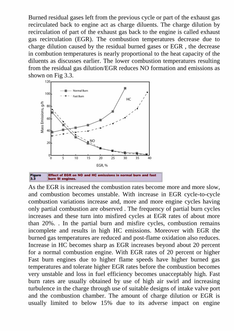
Burned residual gases left from the previous cycle or part of the exhaust gas
recirculated back to engine act as charge diluents. The charge dilution by
recirculation of part of the exhaust gas back to the engine is called exhaust
gas recirculation (EGR). The combustion temperatures decrease due to
charge dilution caused by the residual burned gases or EGR , the decrease
in combution temperatures is nearly proportional to the heat capacity of the
diluents as discusses earlier. The lower combustion temperatures resulting
from the residual gas dilution/EGR reduces NO formation and emissions as
shown on Fig 3.3.
As the EGR is increased the combustion rates become more and more slow,
and combustion becomes unstable. With increase in EGR cycle-to-cycle
combustion variations increase and, more and more engine cycles having
only partial combustion are observed . The frequency of partial burn cycles
increases and these turn into misfired cycles at EGR rates of about more
than 20%. . In the partial burn and misfire cycles, combustion remains
incomplete and results in high HC emissions. Moreover with EGR the
burned gas temperatures are reduced and post-flame oxidation also reduces.
Increase in HC becomes sharp as EGR increases beyond about 20 percent
for a normal combustion engine. With EGR rates of 20 percent or higher
Fast burn engines due to higher flame speeds have higher burned gas
temperatures and tolerate higher EGR rates before the combustion becomes
very unstable and loss in fuel efficiency becomes unacceptably high. Fast
burn rates are usually obtained by use of high air swirl and increasing
turbulence in the charge through use of suitable designs of intake valve port
and the combustion chamber. The amount of charge dilution or EGR is
usually limited to below 15% due to its adverse impact on engine

performance causing power loss, high specific fuel consumption and high
unburned fuel emissions.
Engine Speed :
Volumetric efficiency of the engine changes with speed, it being highest in
the mid-speed range. At high engine speeds the volumetric efficiency
generally decreases resulting in high residual gas dilution. Although heat
transfer rates increase with increase in engine speed as a result of higher
turbulence, but total amount of heat transfer is lower due to shorter cycle
time. This gives higher gas temperatures at higher speeds. However, at high
speeds a shorter time is available for NO formation kinetics. The net result
is a moderate effect of speed on NO although this is specific to the engine
design and operating conditions. Increase in exhaust gas temperatures at
higher speeds enhances post flame oxidation of unburned hydrocarbons. A
reduction of 20 to 50 percent in HC emissions has been observed with
increase in speed from 1000 to 2000 rpm.
Cold Start and Warm-up Phase : Engine cold start and warm-up phase contribute significantly to unburned
hydrocarbons. One of the main sources of HC emissions during cold start
and engine warm-up period is very rich fuel-air ratio needed for ignition
and combustion for several seconds after engine start. During cold start, the
engine has to be over-fuelled 5 to10 times the stoichiometric amount of
gasoline. To obtain robust ignition on the first cycle on cold start, a fuel
vapour- air equivalence ratio above lean threshold limit (f = 0.7-0.9) is
required. This threshold is independent of the engine coolant temperature.
The fuel-air equivalence ratio supplied to the engine during cold start is in
the range, f = 4 to 7. For the first few engine cycles, a large fraction of
inducted fuel is stored as liquid film in the intake port and cylinder as only
the most volatile fractions evaporate when the engine is cold. The liquid
fuel films do not participate in combustion and is emitted as unburned fuel
emissions.
Coolant Temperature
As the coolant temperature is increased, the contribution of piston ring zone
crevice becomes lower due to decrease in gas density within this crevice.
Secondly, the top piston-land side clearance is also reduced due to higher
thermal expansion of the piston. A thinner oil film and reduced fuel vapour
solubility would result in reduced absorption of fuel vapours in engine oil.
Increased postflame oxidation at high temperatures also contributes to
reduction in HC emissions. Increase in coolant temperatures has been
observed to reduce HC emissions by about 0.4 to 1.0 % per K increase in
temperature. An increase in the coolant temperature from 20 to 90º C,

roughly results in 25% lower HC emissions and hence, the need of a rapid
engine warm up is obvious. For reduction of the cold start and warm up HC
emissions, an important area of development is to improve the fuel
injection and delivery to the cylinder with minimum wall wetting. Over-
fuelling during cold start and warm-up is to be kept at a minimum, while
still forming the combustible charge.
Cooling system:
There are mainly two types of cooling systems :
(a) Air cooled system, and
(b) Water cooled system.
Air Cooled System Air cooled system is generally used in small engines
say up to 15-20 kW and in aero plane engines. In this system fins or
extended surfaces are provided on the cylinder walls, cylinder head, etc.
Heat generated due to combustion in the engine cylinder will be conducted
to the fins and when the air flows over the fins, heat will be dissipated to
air. The amount of heat dissipated to air depends upon :
(a) Amount of air flowing through the fins.
(b) Fin surface area.
(c) Thermal conductivity of metal used for fins.
Advantages of Air Cooled System:
Following are the advantages of air cooled system : (a) Radiator/pump is
absent hence the system is light. (b) In case of water cooling system there
are leakages, but in this case there are no leakages. (c) Coolant and
antifreeze solutions are not required. (d) This system can be used in cold
climates, where if water is used it may freeze. Disadvantages of Air Cooled
System (a) Comparatively it is less efficient. (b) It is used in aero planes
and motorcycle engines where the engines are exposed to air directly.

WATER COOLING SYSTEM
In this method, cooling water jackets are provided around the cylinder, cylinder head, valve seats etc.
The water when circulated through the jackets, it absorbs heat of combustion. This hot water will
then be cooling in the radiator partially by a fan and partially by the flow developed by the forward
motion of the vehicle. The cooled water is again recirculated through the water jackets.
Types of Water Cooling System
There are two types of water cooling system :
Thermo Siphon System
In this system the circulation of water is due to difference in temperature (i.e. difference in densities)
of water. So in this system pump is not required but water is circulated because of density difference
only.
Pump Circulation System
In this system circulation of water is obtained by a pump. This pump is driven by means of engine
output shaft through V-belts.
TEXT / REFERENCE BOOKS
1. Giri. N.K. “Automobile Mechanics” Khanna Publishers – New Delhi – 2002.
2. Heldt P.M “High Speed Combustion Engine” Oxford & IBH Publishing Co., Calcutta 1989.
3. Lichty “IC Engines”, Kogakusha Co., Ltd. Tokyo, 1991
4. William H.Crouse, William Harry Crouse “Automobile Mechanics” Tata McGraw-Hill
Education, 2006.
5. Gupta. R.B., "Automobile Enginering", Sathya Prakashan, 8 edit., 2013.
6. Josep Heitner “Automobile Mechanics principles and practice “ CBS publishers,2004.
7. Srinivasan.S “Automobile Mechanics” Tata McGraw-Hill Education, 2003

SCHOOL OF MECHANICAL ENGINEERING
DEPARTMENT OF AUTOMOBILE ENGINEERING
SAU1404 VEHICLE DESIGN CHARACTERISTICS

UNIT 2 PERFORMANCE CURVES
UNIT -II PERFORMANCE CURVES
ROAD PERFORMANCE CURVES: ACCELERATION,
GRADEABILITY AND DRAWBAR PULL
The passenger car performance is based on acceleration, ability to go up a
slope, top speed, fuel economy, noise level and durability. as wheel spin occurs,
the acceleration decreases from the maximum. also the gear is designed for
maximum fuel economy when the engine is developing 80% of its maximum
torque as the automobile is moving at a constant speed. this gives 20%
additional torque for acceleration. the power required to drive an automobile
increases as the cube of the speed. when the power available matches the power
required to push the vehicle, the speed becomes constant. excess power is
required for acceleration and hill climbing. maximum speed is reached when
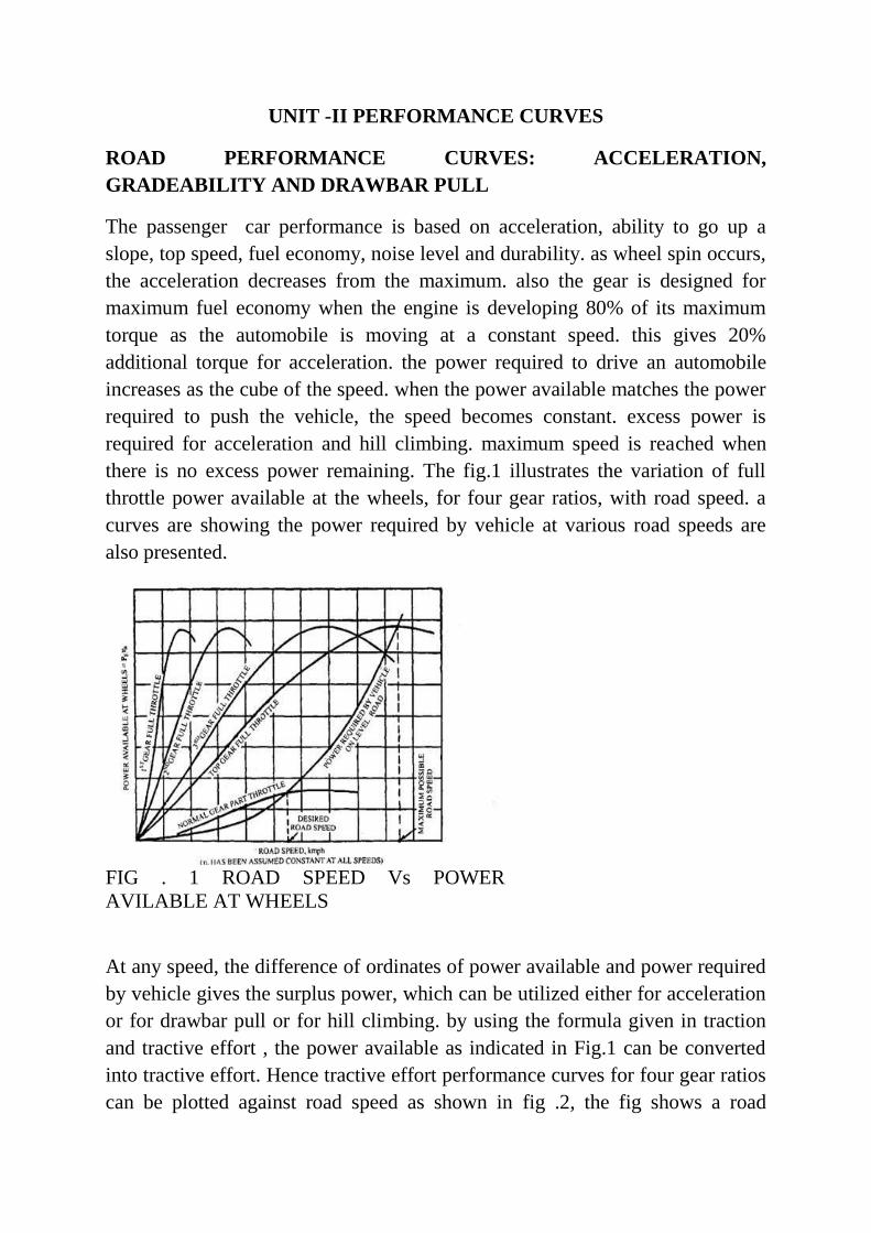
there is no excess power remaining. The fig.1 illustrates the variation of full
throttle power available at the wheels, for four gear ratios, with road speed. a
curves are showing the power required by vehicle at various road speeds are
also presented.
FIG . 1 ROAD SPEED Vs POWER
AVILABLE AT WHEELS
At any speed, the difference of ordinates of power available and power required
by vehicle gives the surplus power, which can be utilized either for acceleration
or for drawbar pull or for hill climbing. by using the formula given in traction
and tractive effort , the power available as indicated in Fig.1 can be converted
into tractive effort. Hence tractive effort performance curves for four gear ratios
can be plotted against road speed as shown in fig .2, the fig shows a road

resistance curve is also presented. the difference between the ordinates of
tractive effort and road resistance at any road speed gives the surplus tractive
effort, which is utilized for acceleration, drawbar pull and hill climbing
FIG.2 ROAD SPEED Vs TRACTIVE EFFORT
the fig.3 illustrate the relationship between the tractive effort and resistance and
road speed
FIG.3 TRACTIVE EFFORT AND RESISTANCE Vs ROAD SPEED
ACCELERATION
when the vehicle is accelerated, its rotating parts are also accelerated depending
upon their moments of inertia and the gear ratio in the drive line. due to this,

weight of the vehicle is increased from 𝑊to 𝑊𝐸 . this increased weight, 𝑊𝐸 is
called the effective or equivalent weight of the vehicle. when surplus power, i.e.
surplus tractive effort is fully utilized for acceleration, then
surplus or excess power= 𝑊𝐸 𝑓 𝑉
3600 𝑘𝑊
maximum acceleration, 𝑓 = 1
𝑊𝐸 𝑠𝑢𝑟𝑝𝑙𝑢𝑠 𝑝𝑜𝑤𝑒𝑟
3600
𝑉
= 1
𝑊𝐸
𝑃𝐸 − 𝑃𝑅 𝜂𝑡 3600
𝑉=
1
𝑊𝐸 𝑃𝐸𝜂𝑡 − 𝑃𝑉
3600
𝑉
= 1
𝑊𝐸 𝑡𝑟𝑎𝑐𝑡𝑖𝑣𝑒 𝑒𝑓𝑓𝑜𝑟𝑡 − 𝑟𝑜𝑎𝑑 𝑟𝑒𝑠𝑖𝑠𝑡𝑎𝑛𝑐𝑒 =
1
𝑊𝐸 (𝐹 − 𝑅)
GRADABILITY
the maximum percentage grade, which a vehicle can negotiate with full
rated condition, is known as gradability. hence
𝑠𝑢𝑟𝑝𝑙𝑢𝑠 𝑝𝑜𝑤𝑒𝑟 = 𝑊 𝑋 𝐺𝑟𝑎𝑑𝑎𝑏𝑖𝑙𝑖𝑡𝑦𝑋 𝑉
100𝑋3600
𝐺𝑟𝑎𝑑𝑎𝑏𝑖𝑙𝑖𝑡𝑦 = 100
𝑊 𝑃𝐸 𝜂𝑡 − 𝑃𝑉
3600
𝑉
= 100
𝑊 𝑡𝑟𝑎𝑐𝑡𝑖𝑣𝑒 𝑒𝑓𝑓𝑜𝑟𝑡 − 𝑟𝑜𝑎𝑑 𝑟𝑒𝑠𝑖𝑠𝑡𝑎𝑛𝑐𝑒 =
100
𝑊 ( 𝐹 − 𝑅)
Drawbar pull
when the excess power is fully utilized for pulling extra load attached to
vehicle then
𝑚𝑎𝑥𝑖𝑚𝑢𝑚 𝑑𝑟𝑎𝑤𝑏𝑎𝑟 𝑝𝑢𝑙𝑙 = 𝑡𝑟𝑎𝑐𝑡𝑖𝑣𝑒 𝑒𝑓𝑓𝑜𝑟𝑡 − 𝑟𝑜𝑎𝑑 𝑟𝑒𝑠𝑖𝑠𝑡𝑎𝑛𝑐𝑒 =
(𝐹 − 𝑅)
road resistance in this case is made up of rolling resistance and air resistance.
the Fig. 1 & 2 shows that maximum surplus power and hence maximum surplus
tractive effort is provided at very low speeds of the vehicle. therefore for
acceleration from start, for climbing steeper gradients and for large drawbar
pull, first gear is best suited.
The maximum road speed is achieved in the gear when power available
equals to power required and tractive effort becomes equal to level road

resistance. if the vehicle is desired to run at a lower speed, the throttle is
adjusted accordingly so that the part throttle power available curve intersects the
power required curve at the desired road speed.
PROBLEMS:
1. The coefficient of rolling resistance of a truck weighing 62293.5N is 0.018
and the coefficient of air resistance is 0.0276 in the formula R = KW + KaAV2,
N, where A in m2 of frontal area and V the speed in kmph. The transmission
efficiency in top gear of 6:2:1 is 90%and that in the second gear of 15:1 is 80%.
The frontal area is 5.574 m2. If the truck has to have a maximum speed of
88kmph in top gear, Calculate:
(a) the engine BP required.
(b) the engine speed if the driving wheels have an effective diameter of
0.8125m
(c) the maximum grade the truck can negotiate at the above engine speed in
second gear.
(d) the maximum draw bar pull available on level at the above engine speed in
second gear
Solution:
In top gear:
(i) 𝑅 = 0.018 𝑊 + 0.0276 𝐴𝑉2
= 0.018 × 62293.5 + 0.0276 × 5.574 88 2
= 1120.3 + 1191.4 = 2312.7 𝑁
Engine 𝐵𝑃 =𝑅𝑉
1000 Ƞ𝑡
=2312.7 ×88
1000 ×0.9 ×3.6 = 62.8 𝑁
(ii) 𝑉 =2𝜋𝑁𝑟
𝐺𝑚 𝑚𝑖𝑛
Hence

𝑁 = 𝑉𝐺
2𝜋𝑟=
88 ×1000
60×
6.2
2𝜋×0.40625=
88×1000 ×6.2
60×2𝜋×0.40625= 3564𝑟𝑝𝑚
In second gear:
(iii) 𝑉 =88
15× 6.2 = 36.4 𝑘𝑚 =
36.4
3.6𝑚 𝑠
𝑅 = 0.018 × 62293.5 + 0.0276 × 5.574 36.4 2
= 1121.3 + 203.8 = 1325.1 𝑁
Assuming that vehicle can climb the maximum grade of 1 in X, then 𝑅 =
1325.1 + 62293.5 𝑋
Now,
𝐹 =𝐵𝑃×Ƞ𝑡×1000
𝑉= 62.8 × 0.8 × 1000 × 3.6 36.4
=4968.8 N
Hence, 1325.1+62293 .5
𝑥= 4968.8
62293.5/x=4968.8−1325.1 = 3643.7
X=62293.5/3643.7=17.1
Maximum grade is 1 in 17.1
(iv) Maximum drawbar pull on level
=tractive effort available tractive effort for resistance on level
=4968.8 1325.1=3643.7 N.
2. An automotive gear box gives three forward speeds and one reverse with a
top gear of unity and bottom and reverse gear ratio of approximately 3:3:1. The
centre distance between the shafts is to be 110mm approximately. Gear teeth of
module 3.25 mm are to be employed.
Sketch the layout of a typical synchromesh gear box for these conditions giving
the number of teeth for the various gear wheels and showing closely how the
different ratios are obtained.

Solution:
Since the pitch is same for all wheel and the centre distance is the same for all
pair of mating wheel, the total number of teeth must be same for each pair.
Thus,
𝑇𝐴 + 𝑇𝐵 = 𝑇𝐶 + 𝑇𝐷 = 𝑇𝐸 + 𝑇𝐹 =110 × 2
3.25= 68
In general practice, for better results the gear ratios are kept in a geometric
progression or approaching to it.
If 𝐺1,𝐺2,𝐺3 𝑎𝑟𝑒 1𝑠𝑡 , 2𝑛𝑑 𝑎𝑛𝑑 3𝑟𝑑or top gear ratios respectively, then
𝐺2 = 𝐺1𝐺3= 1 × 3.3 = 1.817.
First gear ratio, 𝐺1 =𝑇𝐵
𝑇𝐴
𝑇𝐷
𝑇𝐶= 3.3.
Adopting the relation, 𝑇𝐵
𝑇𝐴=
𝑇𝐷
𝑇𝐶= 3.3 = 1.817.
So that the speed ratios 𝑇𝐵
𝑇𝐵𝑎𝑛𝑑
𝑇𝐷
𝑇𝐶 will be as nearly equal as possible.
Hence, 𝑇𝐴 + 𝑇𝐵 = 2.817 𝑇𝐴 = 68,𝑇𝐴 =68
2.187= 24
Therefore, 𝑇𝐵 = 68 − 24 = 44 and also 𝑇𝐶 = 24𝑎𝑛𝑑 𝑇𝐷 = 44
Exact speed reduction 𝐺1 = 44 24 2 = 3.36: 1
Second gear ratio, 𝐺2 =𝑇𝐵
𝑇𝐴 𝑇𝐹
𝑇𝐸= 1.817
𝑇𝐹𝑇𝐸
= 1.817 𝑇𝐴𝑇𝐵
= 1.817 ×24
44= 0.991
𝑇𝐸 =68
1.991= 34.05 𝑎𝑑𝑜𝑝𝑡𝑒𝑑 𝑎𝑛𝑑 𝑇𝐹 = 68 − 34 = 34
Actual ratio, 𝐺2 =34
34 ×
44
24= 1.835: 1
Top gear ratio, 𝐺3 = 1: 1.

Reverse gear ratio:
The presence of an idler gives𝑇𝐼 + 𝑇𝐽 < 68.
Speed ratio = TB
TA
TJ
TI = 3.3 approximately.
Adopting 𝑇𝐼 = 22 𝑎𝑛𝑑 𝑇𝐽 = 40
𝑤𝑖𝑐 𝑔𝑖𝑣𝑒𝑠 𝑡𝑒 𝑛𝑒𝑎𝑟𝑒𝑠𝑡 𝑎𝑝𝑝𝑟𝑜𝑎𝑐𝑖𝑛𝑔 𝑣𝑎𝑙𝑢𝑒 𝑜𝑓 3.3,
The exact reduction = 44
24 ×
40
22= 3.33: 1.
3. A motor vehicle weighs 7975.5 N and its engine develops 14.7 kW at 2500
rpm. At this engine speed the road speed of the car on the top gear is 64.37
km/h. Bottom gear reduction is 3.5:1 and the efficiency of transmission is 88%
on the top and 80% on bottom gear. The diameter of tyres is 0.762 m and the
projected front area of the vehicle is 1.116 m2. The coefficient of air resistance
is 0.0314 N-h2/km2-m2. R=KAV2, where R is resistance in N, K is coefficient
of resistance. A is the front are in m2. V is speed in km/h. Road resistance is
0.023W, N calculate
(a) Speed of car on bottom gear;
b) Tractive effort available at the wheels on top and bottom gear;
(c) Gradient at which car can climb on bottom gear.
(d) The tractive force at the wheels required to start up the car on the level and
attain a speed of 48.28 km/hr in 10s. (Average air resistance may be taken as
half the maximum and acceleration force to vanish at 48.28 km/h speed).
(a) On bottom gear, V=64.37
3.5= 18.4 km/h.
(b) On top gear, tractive effort, F= 𝑃𝐸×Ƞ𝑡×3600
𝑉
=14.7 × 0.88 × 3600
64.37= 723.5 𝑁.
On bottom gear, tractive effort, F =14.7 ×0.8 ×3600
18.4= 2300.9 𝑁
(c) Total resistance in negotiating the grade in bottom gear,
𝑅 = 0.023 × 7975.5 + 0.0314 ×
(1.116 18.4 2 + 7975.5 sin𝜃)
= 183.4 + 11.9 +7975.5 sin θ=195.3 +7975.5 sin θ.
Since available tractive effort is totally utilized in grade climbing, then
2300.9 = 195.3 + 7975.5 sin θ.
Sin θ = 2105.6
7975.5= 0.264.
Hence, tan θ = 0.264 = 1/ 3.648
The grade which the car can negotiate on bottom gear is 1 in 3.648.
(d) The acceleration required to attain a speed of 48.28 km/h in 10s,
𝑓 =𝑉
𝑡=
48.28
3.6 × 10= 1.34 𝑚 𝑠2.
Total resistance on level,
R= 𝑅𝑟 + 𝑅𝑎 = (0.023 × 7975.5) +
(0.5× 0.0314 × 1.116 48.28 2
= 183.4 +40.4 =223.8 N.
(As per the statement in the problem, the air resistance is taken as half the
maximum)
Hence tractive effort required
= R +𝑊
𝑔𝑉 = 223.8 +
7975.5
9.81× 1.34
= 223.8 +1089.4 =1313.1N.
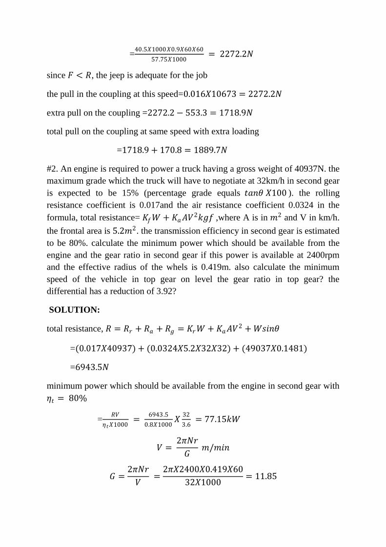
4. An engine is required to power a truck having a gross weight of 40937 N. the
maximum grade which the truck will have to negotiate at 32 km/h in second
gear is expected to be 15% (percentage grade equals tan θ × 100). The rolling
resistance coefficient is 0.017 and the air resistance coefficient 0.0324 in the
formula, total resistance= 𝐾𝑓𝑊 + 𝐾𝑎𝐴𝑉2𝑘𝑔𝑓, where A is in 𝑚2and V in km/h.
the frontal area in 5.2𝑚2 . The transmission efficiency in second gear is
estimated to be 80%. Calculate the minimum power which should be available
from the engine and the gear ratio in second gear if this power is available at
2400 rpm and the effective radius of the wheels is 0.419 m. also calculate the
minimum speed of this vehicle in top gear on level road at the same engine
speed assuming a transmission efficiency of 90% in top gear. What is the gear
ratio in top gear? The differential has a reduction of 3.92.
Solution:
Total resistance,
𝑅 = 𝑅𝑟 + 𝑅𝑎 + 𝑅𝑔 = 𝐾𝑟𝑊 + 𝐾𝑎𝐴𝑉2 + 𝑊𝑠𝑖𝑛𝜃
=0.017 × 40937 + 0.0324 × 5.2 × 32 × 32
+49037 × 0.1481
=40937 (0.017+0.1484) +172.5
=6771+172.5=6943.5 N.
Minimum power which should be available from the engine in speed gear with
Ƞ𝑡
= 80%
= 𝑅𝑉
Ƞ𝑡1000=
6943.5
0.8 ×1000×
32
3.6= 77.15 𝑘𝑊.
We have 𝑉 =2𝜋𝑁𝑟
𝐺𝑚/𝑚𝑖𝑛
𝐺 =2𝜋𝑁𝑟
𝑉=
2𝜋 × 2400 × 0.419 × 60
32 × 1000= 11.85.
Differential has a reduction of 3.92.
Hence second gear ratio is 11.85/3.92:1, i.e. 3.02:1
In top gear with Ƞ𝑡
= 0.9 𝑎𝑛𝑑 with same engine speed, the total resistance on
level
= 0.017× 40937 + 0.0324 × 5.2𝑉2,𝑁
=𝐵𝑃× Ƞ𝑡×3600
𝑉 𝑤𝑒𝑟𝑒 𝑉 𝑖𝑛 𝑘𝑚/.

Hence (696+0.1685𝑉2) v=77.15× 0.9 × 3600 = 249966.
By trail, V=102.1km/h.
Maximum speed of the vehicle on level in top gear=102.1km/h.
Also as before, 𝐺 =2𝜋𝑁𝑟
𝑉=
2𝜋×2400×0.419×60
102.1×1000= 3.72.
Hence top gear is 3.72/3.92:1, i.e. 0.95:1.
5. For typical motor car, the road resistance is given by 23N per 1000 N, the air
resistance by the expression 0.0827𝑉2 , transmission efficiency 88% in top
speed, car weights 19934N when fully loaded. Calculate
a) The Bp kW required for a top speed of 144 km/hr.
b) The acceleration in 𝑚 𝑠2 at 48 km/hr, assuming the torque at 48 km/hr in
the top gear 25% more than at 144km/hr.
c) The Bp kW required to drive the car up a gradient of 1 in 5 at 48 km/hr,
transmission efficiency 80% in bottom gear. The resistance being in N
and V the speed in km/h and g=9.81 𝑚 𝑠2.
Solution:
(a) Total resistance at speed 144km/h
𝑅 = 23 × 19.934 + 0.0827 × 144 × 144 = 458.5 + 1715
= 2173.5
The Bp kw = 𝑅𝑉
3600 Ƞ𝑡 =
2173.5 ×144
0.88 ×3600= 98.8 𝐾𝑊.
(b) 𝑇𝐸1 𝑎𝑛𝑑 𝑇𝐸2𝑎𝑟𝑒 𝑡𝑒 𝑒𝑛𝑔𝑖𝑛𝑒 𝑡𝑜𝑟𝑞𝑢𝑒 𝑎𝑡 𝑡𝑒 𝑠𝑝𝑒𝑒𝑑 𝑜𝑓
14 Km/h respectively, and 𝐹1 𝑎𝑛𝑑 𝐹2 are the corresponding tractive
effort, then as given in the problem,
𝑇𝐸2 = 1.25 𝑇𝐸1
Hence,
𝐹2 = 1.25𝐹1 𝑎𝑠 𝑟𝑎𝑑𝑖𝑢𝑠, 𝑟 𝑖𝑠 𝑠𝑎𝑚𝑒 = 1.25 × 2173.5
= 2717 N.
Total resistance at the speed 48 km/h,
R=458.5+0.0827 × 48 × 48 = 458.5 + 190.5 = 649𝑁.
We have, 𝐹 =𝑤
𝑔𝑓 + 𝑅.
2717 = 19934
9.81𝑓+649.
𝑓 =2068 ×9.81
19934= 1.02 𝑚 𝑠
2.
(c) For the gradient 1 in 5, tan θ = 0.2 and sin θ =0.196.
= 649 +19934 × 0.196 = 649 + 3907 = 4556 𝑁.
The BP required = 𝑅𝑉
Ƞ 3600=
4556 ×48
0.8 ×3600= 76 𝑘𝑊.
6. Determine the gear ratios of a four speed gear box for a vehicle of weight
13341.6 N powered by an engine giving 20.6 kW at 1800 rpm. The vehicle
has a frontal area of 2.23𝑚2 and has a wheel diameter 0.71 m. the maximum
gradient that the car has to negotiate is 1 in 4. The tractive resistance may be
taken as 50 N per 2240 N of the car. The wind resistance is given by 0.03679
𝐴𝑉2,𝑤𝑒𝑟𝑒 𝐴 𝑖𝑠 𝑡𝑒 𝑓𝑟𝑜𝑛𝑡𝑎𝑙 𝑎𝑟𝑒𝑎 in 𝑚2 and V is the vehicle speed in km/h.
assume that the transmission efficiency is 0.75 and that at top gear, the car is
expected to go over a grade of 1 in 40. State any other assumption you make.
Solution: 𝑉 = 2 𝜋𝑁𝑟
𝐺
=2𝜋×1800×0.355 ×60
1000 𝐺=
240.775
𝐺 Km/h.
In the top gear:
𝑅𝑎=0.03679 𝐴 𝑉2
= 0.03679 × 2.23 240.775
𝐺
2
=4756.2
𝐺2 𝑁
𝑅𝑟 =50 × 13341.6
2240= 297.8 𝑁
𝑅𝑔 = 13341.6/ 40
𝑅 = 4756.2
𝐺2+ 297.8 +
13341 .6
40=
4756.2
𝐺2+ 631.3.
Now,
𝐵𝑃 × Ƞ𝑡
=𝑅𝑉
1000

20.6 0.75 = 4756.2
𝐺2+ 631.3
240.775
𝐺
1
1000 .
𝐺3 = 2.73 𝐺2 + 20.6
By trial, the value of G = 4.
In the first gear:
Total resistance, R = 𝑅𝑟 + 𝑅𝑎 + 𝑅𝑔
=297.8 + 4756.2
𝐺2 +
13341 .6
4=
4756.2
𝐺2+ 3633.2
Hence as before,
20.6 × 0.75 = 4756 .2
𝐺2+ 3633.2
240.775
𝐺
1
1000
𝐺2 = 1573𝐺2 + 20.6.
By trial, the value of G = 15.8.
If 𝐺1,𝐺2,𝐺3,𝐺4 are1st, 2nd
,3rd
and top gear ratios respectively, then 𝐺4 = 1.
𝐺1 = 15.8
4= 3.95.
𝑔𝑒𝑛𝑒𝑟𝑎𝑙𝑙𝑦 𝑡𝑒 𝑔𝑒𝑎𝑟 𝑟𝑎𝑡𝑖𝑜𝑠 𝑎𝑟𝑒 𝑖𝑛 𝑔𝑒𝑜𝑚𝑒𝑡𝑟𝑖𝑐 𝑝𝑟𝑜𝑔𝑟𝑒𝑠𝑠𝑖𝑜𝑛 𝑡𝑒𝑛
𝐺32 = 𝐺4 𝐺2 = 𝐺2 𝑎𝑠 𝐺4=1
𝐺22 = 𝐺1𝐺3 = 𝐺1𝐺2
1 2
𝐺2 = 𝐺11 1.5
= 3.95 0.666 = 2.5
𝐺3 = 𝐺11 2 = 2.5 0.5 = 1.581.
The required gear ratios are 1: 1; 1.581:1; 2.5: 1; 3.95:1.
7. The maximum gear box ratio of an engine 75 mm bore and 100 mm stroke
is 4. The pitch diameter of the constantly meshing is 75% of the piston stroke.
If the module is 4.25 mm, calculate the size and number of teeth of gear for a
three speed gear box. Calculate the face width of the constantly meshing gear
using modified lewis formula. The engine torque is 910kgf-cm value of
constant in the lewis formula is 0.07 and the allowable stress is 900kgf/cm2.
Draw the neat sketch of three speed gear layout.
If 𝐺1,𝐺2,𝐺3,𝑎𝑟𝑒 1𝑠𝑡 , 2𝑛𝑑 𝑎𝑛𝑑 𝑡𝑜𝑝 𝑔𝑒𝑎𝑟 𝑟𝑎𝑡𝑖𝑜𝑠 respectively then, 𝐺1 =
4 𝑎𝑛𝑑 𝐺3 = 1.
Taking gear ratios in geometrical progression 𝐺2 = 𝐺1𝐺3 = 4 × 1 = 2
First gear ratio 𝐺1 =𝑇𝐵
𝑇𝐴 𝑇𝐷
𝑇𝐶= 4,𝑔𝑖𝑣𝑖𝑛𝑔
𝑇𝐵
𝑇𝐴 =
𝑇𝐷
𝑇𝐶 = 4 = 2
Adopting 𝑇𝐴 = 𝑇𝑐 =16 to avoid interference, then 𝑇𝐵 = 𝑇𝐷 = 32 adopted.
Then 𝑇𝐴 + 𝑇𝐵 = 𝑇𝑐 + 𝑇𝐷 = 𝑇𝐸 + 𝑇𝐹 = 48.
Pitch diameter of constantly meshing gear, gear A = 0.75× 100 = 75𝑚𝑚.
Pitch diameter of pinion C = module × 𝑛𝑜. 𝑜𝑓 𝑡𝑒𝑒𝑡 = 4.25 × 16 =
68𝑚𝑚.and that gear D and pinion B = 4.25 × 32 = 136𝑚𝑚.
Second gear ratio, 𝐺2 =𝑇𝐵
𝑇𝐴 𝑇𝐹
𝑇𝐸= 2
𝑇𝐹𝑇𝐸
= 2 𝑇𝐴𝑇𝐵
= 2 15
30= 1
𝑇𝐸 = 𝑇𝐹 = 24 𝑎𝑑𝑜𝑝𝑡𝑒𝑑.
Pitch diameter of pinion E and gear F = 4.25 × 24 = 102 𝑚𝑚.
Top gear ratio, 𝐺2 = 1: 1.
𝑇𝑒 =𝐷
2000 𝐹
89.27 = 𝐹 75
2000, 𝑠𝑜 𝑡𝑎𝑡 𝐹 =
89.27 × 2000
75= 2380.5 𝑁
Modified Lewis formula gives, F = 𝑐𝑓𝑏
1000
𝑚
1000
Substituting the values,
2380.5 = 0.07× 8829 × 104 × 𝑏
1000 ×
4.25
1000
𝑏 = 2380.5 × 106
0.07 ×8829 ×104×4.25= 90.6 𝑚𝑚.
−−−−−−−−−−− −−−−−−−−
POWER REQUIRED BY THE VEHICLE:
A driving horse power at the road wheel is proportional to the total
resistance and the EDF to give the required acceleration
𝑣𝑒𝑖𝑐𝑙𝑒 𝑠𝑝𝑒𝑒𝑑 = 𝑉𝑋1000
3600 𝑚 𝑠𝑒𝑐
𝑤𝑎𝑡𝑡 𝑜𝑢𝑡𝑝𝑢𝑡 = 𝐷𝐹𝑋𝑉𝑋1000
3600 𝑘𝑔 −𝑚/𝑠𝑒𝑐
𝐷𝑟𝑖𝑣𝑖𝑛𝑔 𝐻𝑃 = 𝐷𝐹𝑋𝑉𝑋1000
3600𝑋
1
75 𝐻𝑃
𝐷𝐻𝑃 =𝐷𝐹𝑋𝑉
270 𝐻𝑃
𝐵𝑟𝑎𝑘𝑒 𝐻𝑃 = 1.1𝑋𝐷𝐻𝑃
𝐼𝑛𝑑𝑖𝑐𝑎𝑡𝑒𝑑 𝐻𝑃 = 1.1𝑋𝑏𝑝
𝑠𝑖𝑛𝑐𝑒 𝐼𝐻𝑃 > 𝐵𝐻𝑃 > 𝐷𝐻𝑃
RELATION BETWEEN ENGINE SPEED AND VEHICLE SPEED:
Let N- engine speed in rpm
speed of road wheel = 𝑁
𝐺𝑟𝐴 𝑟𝑝𝑚
where G- gear ratio
𝑟𝑎 − 𝑎𝑥𝑙𝑒 𝑟𝑒𝑑𝑢𝑐𝑡𝑖𝑜𝑛
1HP= 735.5 Watts
distance travelled by wheel/min = 𝑁
𝐺𝑟𝑎 𝑋2𝜋𝑅𝑊 𝑚 𝑚𝑖𝑛
𝑅𝑤 = 𝐸𝑓𝑓𝑒𝑐𝑡𝑖𝑣𝑒 𝑤𝑒𝑒𝑙 𝑟𝑎𝑑𝑖𝑢𝑠
vehicle speed, 𝑉 = 𝑁
𝐺 𝑟𝑎2𝜋𝑅𝑊
60
1000𝑟𝑝𝑚/
V= 𝑁.𝑅𝑊
𝐺 .𝑟𝑎 (
2𝜋𝑋60
1000)
𝑁
𝑉=
1000
2𝜋𝑋60 𝐺. 𝑟𝑎𝑅𝑊
𝑁
𝑉= 2.655
𝐺. 𝑟𝑎𝑅𝑊
Assume, gear ratio, G=1:1

axle reduction, 𝑟𝑎 = 3 𝑜𝑟 4
wheel radius, 𝑅𝑊 = 0.2844 ≅ 0.3𝑚
Graphs:
CALCULATION PROCEDURE:
vehicle speed, 𝑉 = 50 𝑘𝑚/
1. Excess Driving Force, EDF = 𝑊
𝑔 (
𝑎
𝐾𝑎) in kg f
2. Driving Force, 𝐷𝐹 = 𝐸𝐷𝐹 + 𝑅𝑇 𝑖𝑛 𝑘𝑔𝑓
3. Driving horse power, 𝐷𝐻𝑃 = 𝐷𝐹𝑋𝑉
270 𝑖𝑛 𝐻𝑃
4. Brake Horse Power, 𝐵𝐻𝑃 = 1.1 𝑋 𝐷𝐻𝑃 𝑖𝑛 𝐻𝑃
5. Indicated Horse Power,𝐼𝐻𝑃 = 1.1 𝑋 𝐵𝐻𝑃 𝑖𝑛 𝐻𝑃
6. Engine Speed, 𝑛 =2.65𝑋𝑉𝑋𝐺𝑋 𝑟𝑎
𝑅𝑊 𝑖𝑛 𝑟𝑝𝑚
Notes:
1. The power available at engine cylinder is called as Indicated Horse
Power.
2. The power available at output shaft of an engine is called as Brake Power.
3. The power available at road and road wheels is called Driving Horse
Power.
FORMULAS FOR CALCULATING EFFICIENCIES AT DIFFERENT
VEHICLE SPEED
0
200
400
600
800
1000
0 10 20 30 40 50 60 70 80
ENG
INE
SPEE
D i
n r
pm
VEHICLE SPEED in km/h
VEHICLE SPEED Vs ENGINE SPEED

1. 𝐹𝑀𝐸𝑃 = 𝑎 + 𝑏 𝑁
1000 + 𝐶(𝑁 1000 )2
where, 𝐹𝑀𝐸𝑃 = 𝐹𝑟𝑖𝑐𝑡𝑖𝑜𝑛𝑎𝑙 𝑀𝑒𝑎𝑛 𝐸𝑓𝑓𝑒𝑐𝑡𝑖𝑣𝑒 𝑃𝑟𝑒𝑠𝑠𝑢𝑟𝑒 𝑖𝑛 𝑏𝑎𝑟
𝑁 = 𝐸𝑛𝑔𝑖𝑛𝑒 𝑟𝑝𝑚 𝑎𝑡 𝑚𝑎𝑥𝑖𝑚𝑢𝑚 𝐵𝐻𝑃
𝑎 = 0.5622
𝑏 = 0.2811
𝑐 = 0.0527
2. 𝐹𝐻𝑃 = 𝐹𝑀𝐸𝑃 𝑋 𝐿 𝐴𝑋 𝑛
4500𝑋100
𝑛 = 𝑁
2 𝑓𝑜𝑟 4 − 5 𝑒𝑛𝑔𝑖𝑛𝑒𝑠.
𝐿𝐴 = 1200 − 1300 𝑐𝑐
3. 𝐼𝐻𝑃 = 𝐵𝐻𝑃 + 𝐹𝐻𝑃
where 𝐼𝐻𝑃 = 𝐼𝑛𝑑𝑖𝑐𝑎𝑡𝑒𝑑 𝐻𝑜𝑟𝑠𝑒 𝑃𝑜𝑤𝑒𝑟
4. To find LA
𝐼𝐻𝑃 =𝐼𝑀𝐸𝑃𝑋𝐿𝐴𝑋𝑛
4500𝑋100
𝐿𝐴 =𝐼𝐻𝑃𝑋4500𝑋100
𝐼𝑀𝐸𝑃𝑋𝑛
after calculating LA, try to check it up the variation between the assumed
value of LA, calculated value of LA. It must be within 5%. If the variation is
more change the assumed value of LA suitably and recalculate the calculated
value of LA until the variation betwee the LA within 5%.After finding LA fix
the number of cylinders.
If LA>1600cc, Assume number of cylinders as 6.
If LA< 1600cc, Assume number of cylinders as 4.
5. To find Bore(B) and Stroke(L):
If B=L , Square engine
If B>L, under square engine
If B<L, Over square engine
For under square engine and over square engine the maximum ratio
between bore and stroke is
𝐵𝑋𝐿 = 1.2
using this find B and L
𝐿𝐴
4=
𝜋
4 𝐵2 𝑋 𝐿
For square engine L=B
FHP from FMEP

BHP from graph
𝐼𝐻𝑃 = 𝐵𝐻𝑃 + 𝐹𝐻𝑃
𝜂𝑚𝑒𝑐 = 𝐵𝐻𝑃
𝐼𝐻𝑃
𝐵𝑀𝐸𝑃 = 𝐵𝐻𝑃𝑋4500𝑋100𝑋2
𝐿𝐴𝑋𝑁
𝑇𝑂𝑅𝑄𝑈𝐸 =𝐵𝐻𝑃𝑋4500
2𝜋𝑁
Graphs:
𝑉 𝑣𝑠 𝜂𝑚𝑒𝑐
𝑉 𝑣𝑠 𝑇
𝑉 𝑣𝑠 𝐵𝑀𝐸𝑃
𝑉 𝑣𝑠 𝐷𝐹
𝑉 𝑣𝑠 𝐵𝐻𝑃, 𝐼𝐻𝑃,𝐹𝐻𝑃
Notes:
1. The maximum Torque must be available at 50% of 𝑉𝑚𝑎𝑥
2. Driving Force and Torque curves must be exactly in similar shape.
3. Starting and ending value of Torque is same
VEHICLE ACCELARATION :
Assume maximum acceleration from vehicle data is 0.9 to 1.05𝑚 𝑠2 for
the vehicle which is having maximum vehicle speed 120 km/h. the maximum
acceleration always occurs at 1/3 of maximum vehicle speed. the acceleration of
the vehicle at maximum speed is zero. now, using the concept draw a smooth
curve for vehicle speed vs. acceleration. now find the acceleration for different
vehicle speed from the above curve
DRIVING FORCE:
𝐷𝐹 = 𝐸𝐷𝐹 + 𝑅𝑇 ………… . 𝑘𝑔𝑓
where EDF= Excess Driving Force in kgf
𝐸𝐷𝐹 = 𝑊
𝑔𝑋
𝑎
𝐾𝑎………… . .𝑘𝑔𝑓
where W= weight in kg
a= acceleration
𝐾𝑎 = 𝑎𝑐𝑐𝑒𝑙𝑒𝑟𝑎𝑡𝑖𝑜𝑛 𝑐𝑜𝑛𝑠𝑡𝑎𝑛𝑡 (0.9)
g= acceleration due to gravity
𝑅𝑇 = total resistance in kgf
.

TEXT / REFERENCE BOOKS
1. Giri. N.K. “Automobile Mechanics” Khanna Publishers – New Delhi – 2002.
2. Heldt P.M “High Speed Combustion Engine” Oxford & IBH Publishing Co., Calcutta 1989.
3. Lichty “IC Engines”, Kogakusha Co., Ltd. Tokyo, 1991
4. William H.Crouse, William Harry Crouse “Automobile Mechanics” Tata McGraw-Hill
Education, 2006.
5. Gupta. R.B., "Automobile Enginering", Sathya Prakashan, 8 edit., 2013.
6. Josep Heitner “Automobile Mechanics principles and practice “ CBS publishers,2004.
7. Srinivasan.S “Automobile Mechanics” Tata McGraw-Hill Education, 2003

SCHOOL OF MECHANICAL ENGINEERING
DEPARTMENT OF AUTOMOBILE ENGINEERING
SAU1404 VEHICLE DESIGN CHARACTERISTICS

UNIT 3 RESISTANCE TO VEHICLE MOTION

UNIT-III RESISTANCE TO VEHICLE MOTION
1. POWER OF PROPULSION
the motion of a vehicle moving on a road is resisted by aerodynamic forces,
known as wind or air resistance, and road resistance, which is generally termed
as rolling resistance. in addition to these two types of resistance, the vehicle has
to overcome grade resistance when it moves up on a gradient, because the
weight of the vehicle is to be lifted through a vertical distance. hence the power
required to propel a vehicle is proportional to the total resistance to its motion
and the speed.
Let, 𝑃𝑉= power required by the vehicle, kW,
𝑃𝑅= engine power required, kW,
𝑉= speed of the vehicle, km/h,
𝜂𝑡= transmission or drive line efficiency,
𝑅= total resistance, N,
𝑅𝑎= air resistance, N
𝑅𝑟= rolling resistance, N
𝑅𝑔= grade resistance, N
Power required to propel a vehicle is given
𝑃𝑉 =𝑅𝑉
3600𝑘𝑊
where 𝑅 = 𝑅𝑎 + 𝑅𝑟 When vehicle moves along a level road.
𝑅 = 𝑅𝑎 + 𝑅𝑟 + 𝑅𝑔 when vehicle moves up a gradient
Calculation of engine power takes into account the losses in transmission. hence
required engine power,
𝑃𝑅 =𝑃𝑉
𝜂𝑡=
𝑅𝑉
3600 𝜂𝑡 kW
1.1 Air Resistance
this is the resistance offered by air to the movement of a vehicle. the air
resistance has an influence on the performance, ride and stability of the vehicle
and depends upon the sizes and shape of the body of the vehicle,its speed and
the wind velocity. hence air resistance
𝑅𝑎 = 𝐾𝑎 𝐴 𝑉2
where 𝐴= projected frontal area, m2
𝑉= speed of the vehicle, km/h,
𝐾𝑎= coefficient of air resistance , N-h2/m
2-km
2
= 0.023 for best streamlined cars
= 0.031 for average cars
=0.045 for trucks and lorries.
1.2 ROLLING RESISTANCE
the magnitude of rolling resistance depends mainly on
a) the nature of road surface
b) the types of tyre
c) the weight of the vehicle
d) the speed of the vehicle
the rolling resistance is expressed as
𝑅𝑟 = 𝐾𝑊
where 𝑊= total weight of the vehicle, N
𝐾= constant of rolling resistance and depends on the nature
of road surface and types of tyre
=0.0059 for good roads
=0.18 for loose sand roads
= 0.015 a representative value
rolling resistance is given by
𝑅𝑟 = 𝑎 + 𝑏𝑉 𝑊
𝑉=speed of the vehicle, km/h

𝑎= 0.015 and 𝑏=0.00016
1.3 GRADE RESISTANCE
the component of the weight of the vehicle parallel to the gradient or the slope
on which it moves is termed as GRADE RESISTANCES. Hence grade
resistance is expressed as
𝑅𝑔 = 𝑊 sin𝜃
where 𝑊= total weight of the vehicle,N
𝜃 = inclination of the slope to the horizontal
𝑃𝑒𝑟𝑐𝑒𝑛𝑡𝑎𝑔𝑒 𝐺𝑟𝑎𝑑𝑒 = 𝑡𝑎𝑛𝜃 𝑋 100, 𝑏𝑢𝑡 𝑓𝑜𝑟 𝑠𝑚𝑎𝑙𝑙 𝑣𝑎𝑙𝑢𝑒𝑠 𝑜𝑓 𝜃, 𝑡𝑎𝑛𝜃 = 𝑠𝑖𝑛𝜃
TRACTION AND TRACTIVE EFFORT
the force available at the contact between the drive wheel tyres and road
is known as tractive effort. the ability of the drive wheels to transmit this effort
without slipping is known as traction. the tractive effort relate to engine power
as follows
engine torque , 𝑇𝐸 = 60000 𝑃𝐸
2 𝜋 𝑁
torque at drive wheels, 𝑇𝑊 = (𝑔. 𝑟 𝑋 𝑎. 𝑟) 𝜂𝑡 𝑇𝐸 = 𝐺 𝜂𝑡 𝑇𝐸 Nm,
Tractive effort, 𝐹 = 𝑇𝑤
𝑟 =
𝑇𝐸 𝐺 𝜂𝑡
𝑟 ,𝑁
where 𝑃𝐸 = 𝑒𝑛𝑔𝑖𝑛𝑒 𝐵𝑃,𝑘𝑊
𝑇𝐸 = 𝑚𝑒𝑎𝑛 𝑒𝑛𝑔𝑖𝑛𝑒 𝑡𝑜𝑟𝑞𝑢𝑒,𝑁𝑚
𝜂𝑡 = 𝑜𝑣𝑒𝑟𝑎𝑙𝑙 𝑡𝑟𝑎𝑛𝑠𝑚𝑖𝑠𝑠𝑖𝑜𝑛 𝑒𝑓𝑓𝑖𝑐𝑖𝑒𝑛𝑐𝑦
𝑔. 𝑟 =gear box gear ratio,
𝑎. 𝑟 = axle ratio,
G= overall gear ratio = = (𝑔. 𝑟 𝑋 𝑎. 𝑟)
r= radius of tyre, m
N= rpm of crankshaft

RELATIONSHIP BETWEEN ENGINE REVOLUTION (N) AND
VEHICLE SPEED (V)
using the relation, 2𝜋𝑟𝑁
𝐺 =
1000 𝑉
60
the ratio between engine revolution, N and vehicle speed V can be
obtained
𝑁
𝑉 =
1000 𝐺
2𝜋𝑟 𝑋 60 = 2.65
𝐺
𝑟
where V = Vehicle speed in km/hr
r = radius of tyre in m
thus 𝑁
𝑉 ratio depends upon the overall gear ratio and wheel diameter. a
vehicle with four different gears has four different values of 𝑁
𝑉 ratio. the
𝑁
𝑉
ratio increases as the wheel diameter increases, the overall gear ratio remaining
constant.
Problems
#1. The engine of a jeep is known to be able to provide 40.5 bkW for propulsion
purpose. in a certain application, the jeep weighing 12549N is required to pull a
trailer of gross weight 10673N at a speed of 57.75km/h in top gear on level. the
resistance to motion is given by the equation 𝑅 = 𝑎𝑊 + 𝑏 𝑉2, where a=0.016
and b=0.055, W is in N and V in km/h. find out the jeep is adequate for the job,
if transmission efficiency is 90%. What is the pull in the coupling at this speed ?
If the available power is just utilised in top gear by suitably loading the trailer,
what is the pull in the coupling at 57.75km/h?
SOLUTION:
Total weight, W=12459+10673= 23132N.
resistance to motion, 𝑅 = 𝑎𝑊 + 𝑏 𝑉2 = 0.016𝑊 + 0.055 𝑉2
= 0.016𝑋23132 + 0.055 57.752
= 370.11 + 183.20 = 553.32𝑁
Tractive effort, 𝐹 = 𝐵𝑃 𝑋 1000𝑋 𝜂𝑡
𝑉, where V in m/s
=40.5𝑋1000𝑋0.9𝑋60𝑋60
57.75𝑋1000 = 2272.2𝑁
since 𝐹 < 𝑅, the jeep is adequate for the job
the pull in the coupling at this speed=0.016𝑋10673 = 2272.2𝑁
extra pull on the coupling =2272.2 − 553.3 = 1718.9𝑁
total pull on the coupling at same speed with extra loading
=1718.9 + 170.8 = 1889.7𝑁
#2. An engine is required to power a truck having a gross weight of 40937N. the
maximum grade which the truck will have to negotiate at 32km/h in second gear
is expected to be 15% (percentage grade equals 𝑡𝑎𝑛𝜃 𝑋100 ). the rolling
resistance coefficient is 0.017and the air resistance coefficient 0.0324 in the
formula, total resistance= 𝐾𝑓𝑊 + 𝐾𝑎𝐴𝑉2𝑘𝑔𝑓 ,where A is in 𝑚2 and V in km/h.
the frontal area is 5.2𝑚2. the transmission efficiency in second gear is estimated
to be 80%. calculate the minimum power which should be available from the
engine and the gear ratio in second gear if this power is available at 2400rpm
and the effective radius of the whels is 0.419m. also calculate the minimum
speed of the vehicle in top gear on level the gear ratio in top gear? the
differential has a reduction of 3.92?
SOLUTION:
total resistance, 𝑅 = 𝑅𝑟 + 𝑅𝑎 + 𝑅𝑔 = 𝐾𝑟𝑊 + 𝐾𝑎𝐴𝑉2 + 𝑊𝑠𝑖𝑛𝜃
=(0.017𝑋40937) + (0.0324𝑋5.2𝑋32𝑋32) + (49037𝑋0.1481)
=6943.5𝑁
minimum power which should be available from the engine in second gear with
𝜂𝑡 = 80%
=𝑅𝑉
𝜂𝑡𝑋1000 =
6943.5
0.8𝑋1000𝑋
32
3.6 = 77.15𝑘𝑊
𝑉 = 2𝜋𝑁𝑟
𝐺 𝑚/𝑚𝑖𝑛
𝐺 =2𝜋𝑁𝑟
𝑉 =
2𝜋𝑋2400𝑋0.419𝑋60
32𝑋1000= 11.85

Differential has a reduction of 3.92
hence second gear ratio is 11.85 3.92 ∶ 1 𝑖𝑒 3.02 ∶ 1
In top gear with 𝜂𝑡 = 0.9 and with same engine speed, the total resistance on
level
= ( 0.017𝑋40937) + (0.0324𝑋 5.2 𝑉2),𝑁
= 𝐵𝑃 𝑋 𝜂𝑡 𝑋3600
𝑉 𝑤𝑒𝑟𝑒 𝑉 𝑖𝑛 𝑘𝑚/
hence 696 + 0.1685𝑉2 𝑉 = 77.15𝑋0.9𝑋3600 = 249966
By trial 𝑉 = 102.1𝑘𝑚/
maximum speed of the vehicle on level in top gear= 102.1 𝑘𝑚/
Also as before 𝐺 =2𝜋𝑁𝑟
𝑉=
2𝜋𝑋2400𝑋0.419𝑋60
102.1𝑋1000= 3.72
hence top gear ratio is 3.72 3.92 ∶ 1 𝑖𝑒 0.95 ∶ 1
#3. A truck weighs 100111N and the engine develops 97bkW at 2400rpm. the
transmission efficiency is 90% in top gear of 3.4:1 and 85% in third gear of
8.4:1. the performance of the vehicle is such that it will just reach a speed of
86.8km/h at 2400rpm at wide open throttle when running on the level in still air,
and at the same engine speed in third gear it will just climb a gradient of 1 in 14.
if the total resistance in N is given by the formula
𝑅 = 𝐾𝑊 + 𝐾𝑎𝐴𝑉2 + 𝑊𝑠𝑖𝑛𝜃,
where A is in 𝑚2, V in km/h and W in N, calculate K and 𝐾𝑎 and hence the
engine power required for climbing a grade of 1in 40 at 48km/h in top gear.
how much more weight can be added to the vehicle to use the engine power
fully under the above condition. Frontal area of truck = 5.575𝑚2
SOLUTION:
in the top gear on the level road with 𝑉 = 86.8 𝑘𝑚/,
tractive effort, 𝐹 =𝐵𝑃𝜂𝑡𝑋3600
𝑉=
97𝑋0.9𝑋3600
86.8= 3621𝑁,
tractive effort has been utilised to overcome resistance, then

3621 = 𝐾𝑋100111 + 𝐾𝑎𝑋5.575 (86.82)
3621 = 100111𝐾 + 42000𝐾𝑎 ………………………… . 𝑖
in third gear with same engine speed, 𝑉 =86.8𝑋3.4
8.4= 35.1𝑘𝑚/,
tractive effort, 𝐹 =97𝑋0.85𝑋3600
35140= 8456.4 𝑁
this tractive effort has been utilised to overcome the grade of 1 in 14 at
35.1km/h
8456.4 = 100111𝐾 + 𝐾𝑎𝑋5.575 35.12 + (100111 14
1305.6 = 100111𝐾 + 6860 𝐾𝑎 ……………………… . 𝑖𝑖
subtracting equation i&ii gives
𝐾𝑎 =2315.4
35140= 0.06589
substituting the value of 𝐾𝑎 𝑖𝑛 𝑒𝑞𝑢𝑎𝑡𝑖𝑜𝑛 𝑖 ,
𝐾 = 3621−2767.4
100111=
853.6
100111= 0.00852,
hence 𝑅 = 0.00852𝑊 + 0.06589𝐴𝑉2 + 𝑊𝑠𝑖𝑛𝜃
total resistance in climbing the grade of 1 in 40 at 48km/h in top gear,
𝑅 = 0.00852𝑋100111 + 0.06589𝑋5.575 482 + (100111 40 )
= 852.9 + 846.3 + 2502.8 = 4202𝑁
engine power= 𝑅𝑉
3600𝜂𝑡=
4202𝑋48
3600𝑋0.9= 62.25𝑘𝑊
tractive effort, 𝐹 = 97𝑋0.9𝑋3600
48= 6547.5𝑁
hence tractive effort for drawbar pull= 6547.5 − 4202 = 2345.5 𝑁
if W is the weight added to utilise this extra tractive effort, then
2345.5 = 0.00852𝑊 + (𝑊 40) = 0.00852 + 0.025 𝑊
𝑊 = 2345.5 0.03352 = 69973𝑁

POWER REQUIRED BY THE VEHICLE:
A driving horse power at the road wheel is proportional to the total
resistance and the EDF to give the required acceleration
𝑣𝑒𝑖𝑐𝑙𝑒 𝑠𝑝𝑒𝑒𝑑 = 𝑉𝑋1000
3600 𝑚 𝑠𝑒𝑐
𝑤𝑎𝑡𝑡 𝑜𝑢𝑡𝑝𝑢𝑡 = 𝐷𝐹𝑋𝑉𝑋1000
3600 𝑘𝑔 −𝑚/𝑠𝑒𝑐
𝐷𝑟𝑖𝑣𝑖𝑛𝑔 𝐻𝑃 = 𝐷𝐹𝑋𝑉𝑋1000
3600𝑋
1
75 𝐻𝑃
𝐷𝐻𝑃 =𝐷𝐹𝑋𝑉
270 𝐻𝑃
𝐵𝑟𝑎𝑘𝑒 𝐻𝑃 = 1.1𝑋𝐷𝐻𝑃
𝐼𝑛𝑑𝑖𝑐𝑎𝑡𝑒𝑑 𝐻𝑃 = 1.1𝑋𝑏𝑝
𝑠𝑖𝑛𝑐𝑒 𝐼𝐻𝑃 > 𝐵𝐻𝑃 > 𝐷𝐻𝑃
RELATION BETWEEN ENGINE SPEED AND VEHICLE SPEED:
Let N- engine speed in rpm
speed of road wheel = 𝑁
𝐺𝑟𝐴 𝑟𝑝𝑚
where G- gear ratio
𝑟𝑎 − 𝑎𝑥𝑙𝑒 𝑟𝑒𝑑𝑢𝑐𝑡𝑖𝑜𝑛
1HP= 735.5 Watts
distance travelled by wheel/min = 𝑁
𝐺𝑟𝑎 𝑋2𝜋𝑅𝑊 𝑚 𝑚𝑖𝑛
𝑅𝑤 = 𝐸𝑓𝑓𝑒𝑐𝑡𝑖𝑣𝑒 𝑤𝑒𝑒𝑙 𝑟𝑎𝑑𝑖𝑢𝑠
vehicle speed, 𝑉 = 𝑁
𝐺 𝑟𝑎2𝜋𝑅𝑊
60
1000𝑟𝑝𝑚/
V= 𝑁.𝑅𝑊
𝐺 .𝑟𝑎 (
2𝜋𝑋60
1000)
𝑁
𝑉=
1000
2𝜋𝑋60 𝐺. 𝑟𝑎𝑅𝑊

𝑁
𝑉= 2.655
𝐺. 𝑟𝑎𝑅𝑊
Assume, gear ratio, G=1:1
axle reduction, 𝑟𝑎 = 3 𝑜𝑟 4
wheel radius, 𝑅𝑊 = 0.2844 ≅ 0.3𝑚
Graphs:
CALCULATION PROCEDURE:
vehicle speed, 𝑉 = 50 𝑘𝑚/
1. Excess Driving Force, EDF = 𝑊
𝑔 (
𝑎
𝐾𝑎) in kg f
2. Driving Force, 𝐷𝐹 = 𝐸𝐷𝐹 + 𝑅𝑇 𝑖𝑛 𝑘𝑔𝑓
3. Driving horse power, 𝐷𝐻𝑃 = 𝐷𝐹𝑋𝑉
270 𝑖𝑛 𝐻𝑃
4. Brake Horse Power, 𝐵𝐻𝑃 = 1.1 𝑋 𝐷𝐻𝑃 𝑖𝑛 𝐻𝑃
5. Indicated Horse Power,𝐼𝐻𝑃 = 1.1 𝑋 𝐵𝐻𝑃 𝑖𝑛 𝐻𝑃
6. Engine Speed, 𝑛 =2.65𝑋𝑉𝑋𝐺𝑋 𝑟𝑎
𝑅𝑊 𝑖𝑛 𝑟𝑝𝑚
Notes:
1. The power available at engine cylinder is called as Indicated Horse
Power.
2. The power available at output shaft of an engine is called as Brake Power.
3. The power available at road and road wheels is called Driving Horse
Power.
0
200
400
600
800
1000
0 10 20 30 40 50 60 70 80
ENG
INE
SPEE
D i
n r
pm
VEHICLE SPEED in km/h
VEHICLE SPEED Vs ENGINE SPEED

FORMULAS FOR CALCULATING EFFICIENCIES AT DIFFERENT
VEHICLE SPEED
1. 𝐹𝑀𝐸𝑃 = 𝑎 + 𝑏 𝑁
1000 + 𝐶(𝑁 1000 )2
where, 𝐹𝑀𝐸𝑃 = 𝐹𝑟𝑖𝑐𝑡𝑖𝑜𝑛𝑎𝑙 𝑀𝑒𝑎𝑛 𝐸𝑓𝑓𝑒𝑐𝑡𝑖𝑣𝑒 𝑃𝑟𝑒𝑠𝑠𝑢𝑟𝑒 𝑖𝑛 𝑏𝑎𝑟
𝑁 = 𝐸𝑛𝑔𝑖𝑛𝑒 𝑟𝑝𝑚 𝑎𝑡 𝑚𝑎𝑥𝑖𝑚𝑢𝑚 𝐵𝐻𝑃
𝑎 = 0.5622
𝑏 = 0.2811
𝑐 = 0.0527
2. 𝐹𝐻𝑃 = 𝐹𝑀𝐸𝑃 𝑋 𝐿 𝐴𝑋 𝑛
4500𝑋100
𝑛 = 𝑁
2 𝑓𝑜𝑟 4 − 5 𝑒𝑛𝑔𝑖𝑛𝑒𝑠.
𝐿𝐴 = 1200 − 1300 𝑐𝑐
3. 𝐼𝐻𝑃 = 𝐵𝐻𝑃 + 𝐹𝐻𝑃
where 𝐼𝐻𝑃 = 𝐼𝑛𝑑𝑖𝑐𝑎𝑡𝑒𝑑 𝐻𝑜𝑟𝑠𝑒 𝑃𝑜𝑤𝑒𝑟
4. To find LA
𝐼𝐻𝑃 =𝐼𝑀𝐸𝑃𝑋𝐿𝐴𝑋𝑛
4500𝑋100
𝐿𝐴 =𝐼𝐻𝑃𝑋4500𝑋100
𝐼𝑀𝐸𝑃𝑋𝑛
after calculating LA, try to check it up the variation between the assumed
value of LA, calculated value of LA. It must be within 5%. If the variation is
more change the assumed value of LA suitably and recalculate the calculated
value of LA until the variation betwee the LA within 5%.After finding LA fix
the number of cylinders.
If LA>1600cc, Assume number of cylinders as 6.
If LA< 1600cc, Assume number of cylinders as 4.
5. To find Bore(B) and Stroke(L):
If B=L , Square engine
If B>L, under square engine
If B<L, Over square engine
For under square engine and over square engine the maximum ratio
between bore and stroke is
𝐵𝑋𝐿 = 1.2
using this find B and L

𝐿𝐴
4=
𝜋
4 𝐵2 𝑋 𝐿
For square engine L=B
FHP from FMEP
BHP from graph
𝐼𝐻𝑃 = 𝐵𝐻𝑃 + 𝐹𝐻𝑃
𝜂𝑚𝑒𝑐 = 𝐵𝐻𝑃
𝐼𝐻𝑃
𝐵𝑀𝐸𝑃 = 𝐵𝐻𝑃𝑋4500𝑋100𝑋2
𝐿𝐴𝑋𝑁
𝑇𝑂𝑅𝑄𝑈𝐸 =𝐵𝐻𝑃𝑋4500
2𝜋𝑁
Graphs:
𝑉 𝑣𝑠 𝜂𝑚𝑒𝑐
𝑉 𝑣𝑠 𝑇
𝑉 𝑣𝑠 𝐵𝑀𝐸𝑃
𝑉 𝑣𝑠 𝐷𝐹
𝑉 𝑣𝑠 𝐵𝐻𝑃, 𝐼𝐻𝑃,𝐹𝐻𝑃
Notes:
1. The maximum Torque must be available at 50% of 𝑉𝑚𝑎𝑥
2. Driving Force and Torque curves must be exactly in similar shape.
3. Starting and ending value of Torque is same.


TEXT / REFERENCE BOOKS
1. Giri. N.K. “Automobile Mechanics” Khanna Publishers – New Delhi – 2002.
2. Heldt P.M “High Speed Combustion Engine” Oxford & IBH Publishing Co., Calcutta 1989.
3. Lichty “IC Engines”, Kogakusha Co., Ltd. Tokyo, 1991
4. William H.Crouse, William Harry Crouse “Automobile Mechanics” Tata McGraw-Hill
Education, 2006.
5. Gupta. R.B., "Automobile Enginering", Sathya Prakashan, 8 edit., 2013.
6. Josep Heitner “Automobile Mechanics principles and practice “ CBS publishers,2004.
7. Srinivasan.S “Automobile Mechanics” Tata McGraw-Hill Education, 2003

SCHOOL OF MECHANICAL ENGINEERING
DEPARTMENT OF AUTOMOBILE ENGINEERING
SAU1404 VEHICLE DESIGN CHARACTERISTICS
UNIT 4 ENGINE DESIGN

UNIT- IV ENGINE DESIGN
PV DIAGRAMS
Pressure-Volume (PV) diagrams are a primary visualization tool for the study of heat
engines. Since the engines usually involve a gas as a working substance, the ideal gas
law relates the PV diagram to the temperature so that the three essential state variables
for the gas can be tracked through the engine cycle. Since work is done only when the
volume of the gas changes, the diagram gives a visual interpretation of work done. Since
the internal energy of an ideal gas depends upon its temperature, the PV diagram along
with the temperatures calculated from the ideal gas law determine the changes in the
internal energy of the gas so that the amount of heat added can be evaluated from the first
law of thermodynamics. In summary, the PV diagram provides the framework for the
analysis of any heat engine which uses a gas as a working substance.
For a cyclic heat engine process, the PV
diagram will be closed loop. The area inside the
loop is a representation of the amount of work
done during a cycle. Some idea of the relative
efficiency of an engine cycle can be obtained by
comparing its PV diagram with that of a Carnot
cycle, the most efficient kind of heat engine
cycle.
FRICTIONAL MEAN EFFECTIVE PRESSURE
Experimentally, the power taken by the friction between the engine's components ( Pf ) is
found by substracting the measured power at the crankshaft (P) from the potential power
that we can obtained from the measured gas pressure acting inside the cylinder(s) (Pi).
Pf = Pi − P
(1)
Dividing equation (1) by the measured volumetric flow rate (Qm), we get an equation of
pressure:
FMEPd = IMEPd − BMEPd
(2)
Where:

FMEPd = friction mean effective pressure differential
IMEPd = indicated mean effective pressure differential
BMEPd = brake mean effective pressure differential
So, the friction mean effective pressure represents the equivalent pressure «taken
away» by the internal losses.
For reciprocating engines, we usually divide equation (1) by the theoretical volumetric
flow rate, such that we obtain the average values instead of the differential values (see
the BMEP page for more info).
Estimation
A relationship has been well established between the mean piston speed ( vmps ) and the
friction mean effective pressure to make a good estimation. This site goes further by an
attempt to relate it as well to the indicated mean effective pressure:
FMEPd = IMEPd ( 0.09 Ksum + 0.008 vmps )
(3)
Where Ksum is the sum of all values (Kx) for the engine components in use, as presented in
the next table:
Engine component Kx
camshaft 0.20
lifter 0.20
rocker 0.10
crankshaft 0.20
oil pump 0.10
water pump 0.10
fuel pump 0.05
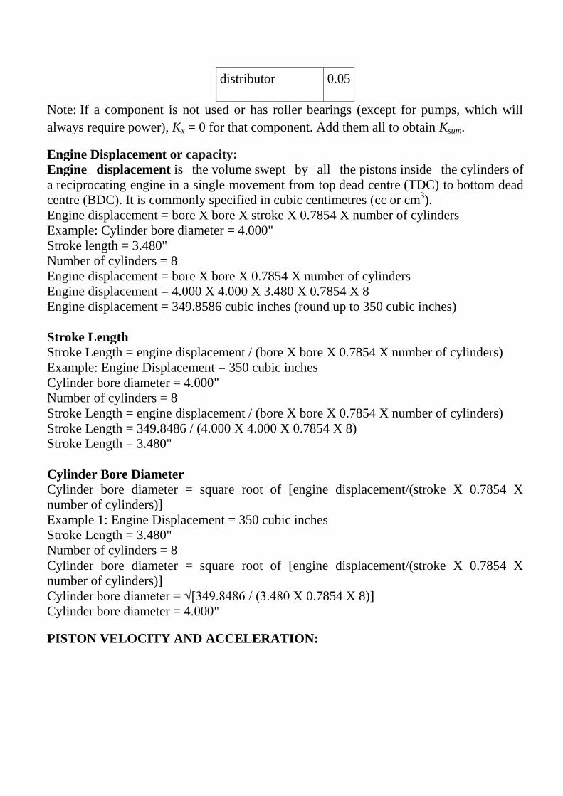
distributor 0.05
Note: If a component is not used or has roller bearings (except for pumps, which will
always require power), Kx = 0 for that component. Add them all to obtain Ksum.
Engine Displacement or capacity:
Engine displacement is the volume swept by all the pistons inside the cylinders of
a reciprocating engine in a single movement from top dead centre (TDC) to bottom dead
centre (BDC). It is commonly specified in cubic centimetres (cc or cm3).
Engine displacement = bore X bore X stroke X 0.7854 X number of cylinders
Example: Cylinder bore diameter = 4.000"
Stroke length = 3.480"
Number of cylinders = 8
Engine displacement = bore X bore X 0.7854 X number of cylinders
Engine displacement = 4.000 X 4.000 X 3.480 X 0.7854 X 8
Engine displacement = 349.8586 cubic inches (round up to 350 cubic inches)
Stroke Length
Stroke Length = engine displacement / (bore X bore X 0.7854 X number of cylinders)
Example: Engine Displacement = 350 cubic inches
Cylinder bore diameter = 4.000"
Number of cylinders = 8
Stroke Length = engine displacement / (bore X bore X 0.7854 X number of cylinders)
Stroke Length = 349.8486 / (4.000 X 4.000 X 0.7854 X 8)
Stroke Length = 3.480"
Cylinder Bore Diameter
Cylinder bore diameter = square root of [engine displacement/(stroke X 0.7854 X
number of cylinders)]
Example 1: Engine Displacement = 350 cubic inches
Stroke Length = 3.480"
Number of cylinders = 8
Cylinder bore diameter = square root of [engine displacement/(stroke X 0.7854 X
number of cylinders)]
Cylinder bore diameter = √[349.8486 / (3.480 X 0.7854 X 8)]
Cylinder bore diameter = 4.000"
PISTON VELOCITY AND ACCELERATION:

Let,
B = bore diameter
L = stroke length
n= length of connecting rod / stroke length (L)
r= crank radius = L/2
In the fig, the piston moved from TDC at a distance x
Now, 𝑥 = (𝑛𝐿 + 𝐿/2) – 𝐶𝑂
From the fig. 𝐶𝑂 = 𝐶𝐷 + 𝐷𝑂
𝐶𝑂 = (𝐿/2) 𝑐𝑜𝑠 𝜃 + 𝑛𝐿 𝑐𝑜𝑠 ∅
𝑥 = (𝑛𝐿 +𝐿
2 ) – (
𝐿
2 𝑐𝑜𝑠 𝜃 + 𝑛𝐿 𝑐𝑜𝑠 ∅) =
𝐿
2 1 − 𝑐𝑜𝑠 𝜃 + 𝑛𝐿 (1 − 𝑐𝑜𝑠 ∅)
𝑥 = 𝐿
2 1 − 𝑐𝑜𝑠 𝜃 + 𝑛𝐿 (1 − (1 −
𝑠𝑖𝑛2 𝜃
8𝑛2 ))
where, cos∅ = 1 −sin 2 𝜃
8𝑛2

𝑥 = 𝐿
2 1 − 𝑐𝑜𝑠 𝜃 +
𝐿
8𝑛𝑠𝑖𝑛2𝜃
Velocity of piston, 𝑉𝑝 = 𝑑𝑥
𝑑𝑦
𝑉𝑝 = 𝑑𝜃
𝑑𝑡[ 𝐿
2𝑠𝑖𝑛 𝜃 +
𝐿
8𝑛 𝑠𝑖𝑛 2𝜃 ]
Now 𝑑𝜃
𝑑𝑡=
2𝜋𝑁
60
𝑉𝑝 = 𝜋𝑁𝐿
6000[𝑠𝑖𝑛 𝜃 +
𝑠𝑖𝑛 2𝜃
4𝑛 ]
Acceleration of piston, 𝑎𝑝 = 𝑑𝑉𝑝
𝑑𝑡
𝑎𝑝 = 𝜋2𝑁2𝐿
6000×30 𝑐𝑜𝑠 𝜃 +
𝑐𝑜𝑠 2𝜃
2𝑛


INERTIA FORCE, GAS FORCE & RESULTANT FORCE:
Inertia force:
Due to the acceleration of reciprocating mass an opposite force is created and it
called as inertia force.
𝐼𝑛𝑒𝑟𝑡𝑖𝑎 𝑓𝑜𝑟𝑐𝑒 = 𝑚 × 𝑎 = 𝑊
𝑔× 𝑎
𝐼.𝐹 = −𝑊
𝑔× 𝑎𝑝
Since, inertia force is acting vertically up add a negative sign. Here ap is
acceleration of the piston in m/s2.
g – acceleration due to gravity
W – weight of reciprocating parts in kgf.
Here, w is the weight of piston, piston pin, piston rings, circlips and one third of the
connecting rod weight.
𝐼.𝐹 = 𝑊
𝑔 .
𝜋2𝑁2𝐿
18×104 𝑐𝑜𝑠 𝜃 + 𝑐𝑜𝑠 2𝜃
2𝑛 in kgf.
Where, 𝑊 = ( 𝑤𝑒𝑖𝑔𝑡 𝑜𝑓 𝑟𝑒𝑐𝑖𝑝𝑟𝑜𝑐𝑎𝑡𝑖𝑛𝑔 𝑝𝑎𝑟𝑡𝑠/𝑐𝑚2) × 𝐵𝑜𝑟𝑒 𝑎𝑟𝑒𝑎 𝑐𝑚2
= ( 𝑤𝑡/ 𝑐𝑚2 ) × 𝜋
4𝐵2
W = ------------- kgf.
From the following table we can find the weight of the inertia parts.
Cylinder
Bore B
mm
weight of reciprocating parts per sq.cm of bore
area
Aluminium alloy pistons in
kgf
C.I pistons in
kgf
60 0.011 0.016
70 0.012 0.018
80 0.014 0.02
90 0.015 0.022
100 0.017 0.024
110 0.018 0.026

120 0.019 0.028
130 0.02 0.03
Gas forces :
Due to the pressure of the gas in the cylinder and combustion chamber a certain
force is exerted on the piston. The force due to gas pressure acting on the piston crown is
known as gas force.
The gas pressure is acting on te piston crown and combustion chamber and the
atmospheric pressure is acting on the bottom side of the piston. The net gas force is equal
to the bottom difference between the pressure on the piston crown and the atmospheric
pressure at bottom side of the piston.
𝐶𝑦𝑙𝑖𝑛𝑑𝑒𝑟 𝑝𝑟𝑒𝑠𝑠𝑢𝑟𝑒 = 𝑔𝑎𝑠 𝑝𝑟𝑒𝑠𝑠𝑢𝑟𝑒 – 𝑏𝑎𝑐𝑘 𝑝𝑟𝑒𝑠𝑠𝑢𝑟𝑒
𝐵𝑎𝑐𝑘 𝑝𝑟𝑒𝑠𝑠𝑢𝑟𝑒 = 1.03 𝑘𝑔𝑓/𝑐𝑚2
Gas force = cylinder pressure x bore area
If we know, gas pressure from zero to 720o crank angle we can easily determine gas
force. Since piston starts from TDC and that time 𝜃 = 0.
0o – 180
o – power stroke
1800 – 360
o – exhaust stroke
360o – 540
o – suction stroke
540o – 720
o – compression stroke.
1. During power stroke, pressure changes frm max. To min.
2. During exhaust and suction strokes the pressure is almost constant.
3. During comp. Stroke the pressure changes from min. To max.
Gas pressure may be assumed as,
For exhaust stroke – 1.12 to 1.16 kgf/cm2
For suction stroke – 0.95 to 0.98 kgf/cm2

For power and compression stroke gas pressure can be determined from the PV diagram.
The absolute gas pressure existing in the cylinder can be obtained from the PV diagram.
For this it is necessary to find the distance through which the piston has travelled from
the top end of the stroke ( for power stroke ). Where the crank has turned through
different angles from 0o – 180
o. This can be done by constructing the diagram as
described below.
CA = length of connecting rod = nL
AD = base length of PV diagram.
AA12 = L
1. Draw line CA as shown in figure. From C draw a circle with stroke length as a
diameter at point o.
2. Divide this circle into 24 equal parts, i.e. each segment is 15o with C1, C2, C3,...as
centres an CA as a radius cut arcs at A1, A2, A3,...... A12.
3. Draw a line AD conveniently at any angle from A. Such that AB is the base length
of the PV diagram. Now join A12 with D.
4. Draw lines parallel to A12D through A11, A10,....

5. Now we have points D11,D10,...on AD.
6. Transforms these point in PV diagram.
7. Corresponding to these points gas pressure can be determined from PV – diagram
in both power and compression stroke.
Resultant force:
The algebraic sum of the gas force and inertia force gives the resultant force.
R.F = G.F + I.F
Calculation:
I.F = - 𝑊
𝑔 .
𝜋2𝑁2𝐿
18×104 cos𝜃 + cos 2𝜃
2𝑛
W= (wt/ cm2)
× 𝜋
4𝐵2
= 0.0139 x 𝜋
4 (7.869)
2
W= 0.68 kgf.
I.F = −0.68
9.81
𝜋2× 3816 2×7.689
18×104× 1.25
I.F = - 544.4 kgf.
G.F = cylinder pressure x bore area
= (gas pr – back pr) x 𝜋
4𝐵2
= (74 – 1.03)x 𝜋
4(7.869)2
= 3548.733 kgf.


SIDE THRUST:
Side thrust is defined as the force or thrust acting on the cylinder walls due to
angularity of the connecting rod.
Since side thrust is maximum only in the power stroke, it’s enough to find side
thrust only for power stroke.i.e between 0o to 180
o.
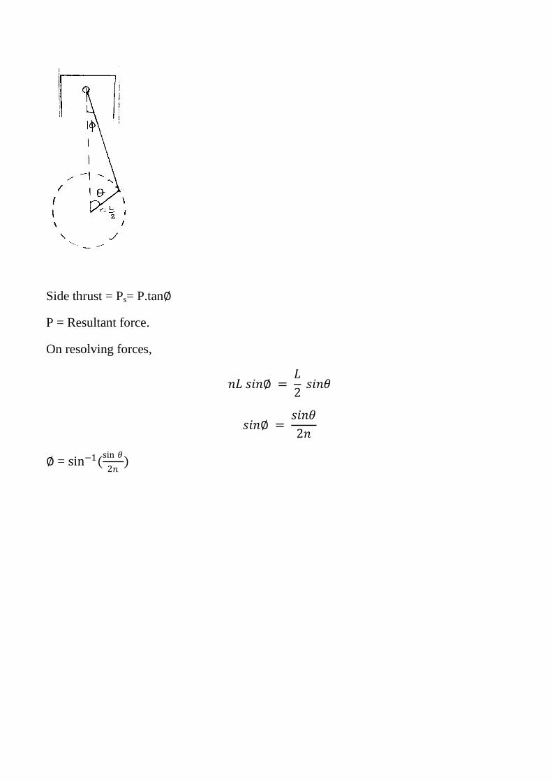
Side thrust = Ps= P.tan∅
P = Resultant force.
On resolving forces,
𝑛𝐿 𝑠𝑖𝑛∅ = 𝐿
2 𝑠𝑖𝑛𝜃
𝑠𝑖𝑛∅ = 𝑠𝑖𝑛𝜃
2𝑛
∅ = sin−1(sin 𝜃
2𝑛)
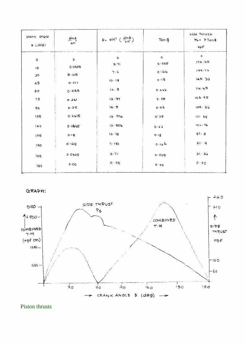
Piston thrusts

During the power strokes, combustion pressures force the piston downwards.
However, the piston does not bear evenly against the walls of the cylinder, but is thrust
against the sides of the cylinder. This is caused by the angularity of the connecting rod
(Figure 1). The combustion pressures force the piston downwards, and the connecting rod
offers resistance, but it does this at an angle. The result is a side thrust of the piston
against the cylinder wall, as shown. The piston also has a side thrust during the
compression stroke, but this is on the opposite side of the cylinder. Also, this is a lesser
thrust because the downward force from compression is much less than the downward
force of combustion. The thrusts are sometimes referred to as
the major and minor thrusts. Because the thrust during the power stroke (major thrust) is
most important, this side of the engine is often referred to as the thrust side of the engine.
It is necessary to know about the thrust side of an engine because the pistons in most
engines have to be installed in a particular way. Pistons are often provided with a mark to
show how they should be fitted in relation to the front of the engine.
Thrusts occur on both the upstrokes and the down-strokes, but the major thrust is
during the power stroke.
Major Thrust Side:
As a piston is pushed down the cylinder on its power stroke, the piston will
meet resistance as it tries to turn the crankshaft.
The greater the load on an engine, the greater this resistance will be. The resistance will
cause the piston to be pushed to one side with considerable force, as it is also pushed
down the bore by the hot expanding air/fuel gasses above it.

This side force is known as thrust, and it causes one side of the cylinder walls to wear at a
faster rate than the rest of the cylinder wall. The side of the engine where this thrust acts
is known as the thrust side of the engine.
Because there is extra wear on this side of the engine, the connecting rod will often have
an oil squirt hole in it, so that oil under pressure from the crankshaft can be squirted on to
the cylinder wall on the thrust side, in order to minimise wear and remove excess heat.
That is why it is so important to note any mark on the crown of the piston. Such marks
will generally point toward the front of the engine, or one particular side of the engine.
For example, in the case of the Lean 5 HP engine, the mark on the crown of the
piston points toward the camshaft side of the engine.
It is also important to note that as well as a major thrust side, each engine also has
a minor thrust side, which is opposite to the major thrust side. As the piston moves up on
its compression stroke, and it meets the resistance of the fresh air/fuel mixture,
this resistance will tend to force the piston off too one side as it moves upward on its
compression stroke.
See also the glossary explanation for minor thrust side for more information.

TEXT / REFERENCE BOOKS
1. Giri. N.K. “Automobile Mechanics” Khanna Publishers – New Delhi – 2002.
2. Heldt P.M “High Speed Combustion Engine” Oxford & IBH Publishing Co., Calcutta 1989.
3. Lichty “IC Engines”, Kogakusha Co., Ltd. Tokyo, 1991
4. William H.Crouse, William Harry Crouse “Automobile Mechanics” Tata McGraw-Hill
Education, 2006.
5. Gupta. R.B., "Automobile Enginering", Sathya Prakashan, 8 edit., 2013.
6. Josep Heitner “Automobile Mechanics principles and practice “ CBS publishers,2004.
7. Srinivasan.S “Automobile Mechanics” Tata McGraw-Hill Education, 2003

SCHOOL OF MECHANICAL ENGINEERING
DEPARTMENT OF AUTOMOBILE ENGINEERING
SAU1404 VEHICLE DESIGN CHARACTERISTICS

UNIT 5 GEAR RATIOS

UNIT-5 GEAR RATIOS
1.1 HISTORY OF GEARS
Indian history as per our mythological stories is more than 12,000 years old. Since
then people living here have been striving to improve the living conditions. We
also know that earlier people were living in the caves and the doors of the caves
were made of granite. How were these heavy doors opened and closed? They were
opened and closed by none other than a system with gear mechanism, wheel, lever
and rope drives. However, the documented evidence has been lost due to
destruction by the invaders and improper storing of palm leaf literature. The guru
Kula method of teaching and passing of the information from mouth to ear
procedure and keeping some of the advances as closely guarded secret have
resulted in poor dissemination of the knowledge and documentation. But, the
knowledge of gears has gone from India to east through some of the globe trotters
from China as back as 2600 years BC. They have used the gears then ingeniously
in chariots for measuring the speed and other mechanisms. Primitive gears shown
in Fig. 1 were first used in door drive mechanism in temples and caves, and water
lifting mechanisms 2600 B.C. in India and elsewhere.
1.11 Introduction
We have discussed earlier that the slipping of a belt or rope is a common
phenomenon, in the transmission of motion or power between two shafts. The

effect of slipping is to reduce the velocity ratio of the system. In precision
machines, in which a definite velocity ratio is of importance (as in watch
mechanism), the only positive drive is by gears or toothed wheels. A gear drive is
also provided, when the distance between the driver and the follower is very small.
1.2 DEFINITION OF GEARS
Gears are toothed members which transmit power / motion between two shafts
by meshing without any slip. Hence, gear drives are also called positive drives.
In any pair of gears, the smaller one is called pinion and the larger one is called
gear immaterial of which is driving the other. When pinion is the driver, it
results in step down drive in which the output speed decreases and the torque
increases. On the other hand, when the gear is the driver, it results in step up
drive in which the output speed increases and the torque decreases.
Classification of Gears
The gears or toothed wheels may be classified as follows:
1. According to the position of axes of the shafts. The axes of the two shafts
between which the motion is to be transmitted, may be
(a) Parallel, (b) Intersecting, and (c) Non-intersecting and non-parallel.
The two parallel and co-planar shafts connected by the gears. These gears are
called spur gears and the arrangement is known as spur gearing. These gears have
teeth parallel to the axis of the wheel .Another name given to the spur gearing is
helical gearing, in which the teeth are inclined to the axis. The single and double
helical gears connecting parallel shafts are shown in Fig. respectively. The object
of the double helical gear is to balance out the end thrusts that are induced in single
helical gears when transmitting load. The double helical gears are known as
herringbone gears. A pair of spur gears is kinematic ally equivalent to a pair of
cylindrical discs, keyed to a parallel shaft having line contact. The two non-parallel
or intersecting, but coplanar shafts connected by gears is shown in Fig. These gears
are called bevel gears and the arrangement is known as bevel gearing. The bevel

gears, like spur gears may also have their teeth inclined to the face of the bevel, in
which case they are known as helical bevel gears.
The two non-intersecting and non-parallel i.e. non-coplanar shafts connected by
gears .These gears are called skew bevel gears or spiral gears and the arrangement
is known as skew bevel gearing or spiral gearing. This type of gearing also has a
line contact, the rotation of which about the axes generates the two pitch surfaces
known as hyperboloids.
2. According to the peripheral velocity of the gears. The gears, according to the
peripheral velocity of the gears, may be classified as:
(a) Low velocity, (b) Medium velocity, and (c) High velocity
The gears having velocity less than 3 m/s are termed as low velocity gears and
gears having velocity between 3 and 15 m / s are known as medium velocity gears.
If the velocity of gears is more than 15 m / s, then these are called high speed
gears.
3. According to the type of gearing. The gears, according to the type of gearing,
may be
Classified as:
(a) External gearing, (b) internal gearing, and (c) Rack and pinion.

In external gearing, the gears of the two shafts mesh externally with each other.
The larger of these two wheels is called spur wheel or gear and the smaller wheel
is called pinion. In an external gearing, the motion of the two wheels is always
unlike, as shown in Fig. In internal gearing, the gears of the two shafts mesh
internally with each other as shown in Fig. The larger of these two wheels is called
annular wheel and the smaller wheel is called pinion. In an internal gearing, the
motion of the wheels is always like as shown in Fig. Sometimes, the gear of a shaft
meshes externally and internally with the gears in a *straight line, as shown in Fig.
Such a type of gear is called rack and pinion. The straight line gear is called rack
and the circular wheel is called pinion. A little consideration will show that with
the help of a rack and pinion, we can convert linear motion into rotary motion and
vice-versa as shown in Fig.
4. According to the position of teeth on the gear surface. The teeth on the gear
surface may be
(a) Straight, (b) Inclined, and (c) Curved.
We have discussed earlier that the spur gears have straight teeth whereas helical
gears have their teeth inclined to the wheel rim. In case of spiral gears, the teeth are
curved over the rim surface.
Terms used in Gears

The following terms, which will be mostly used in this chapter, should be clearly
understood at this stage. These terms are illustrated in Fig. 28.6.
1. Pitch circle. It is an imaginary circle which by pure rolling action, would give
the same motion as the actual gear.
2. Pitch circle diameter. It is the diameter of the pitch circle. The size of the gear is
usually specified by the pitch circle diameter. It is also called as pitch diameter.
3. Pitch point. It is a common point of contact between two pitch circles.
4. Pitch surface. It is the surface of the rolling discs which the meshing gears have
replaced at the pitch circle.
5. Pressure angle or angle of obliquity. It is the angle between the common normal
to two gear teeth at the point of contact and the common tangent at the pitch point.
It is usually denoted by φ. The standard pressure angles are 1 14 /2° and 20°.
6. Addendum. It is the radial distance of a tooth from the pitch circle to the top of
the tooth.
7. Dedendum. It is the radial distance of a tooth from the pitch circle to the bottom
of the tooth.
8. Addendum circle. It is the circle drawn through the top of the teeth and is
concentric with the pitch circle.
9. Dedendum circle. It is the circle drawn through the bottom of the teeth. It is also
called root circle.
10. Circular pitch. It is the distance measured on the circumference of the pitch
circle from a point of one tooth to the corresponding point on the next tooth. It is
usually denoted by pc. Mathematically,
Circular pitch, pc = π D/T
Where D = Diameter of the pitch circle, and
T = Number of teeth on the wheel.

A little consideration will show that the two gears will mesh together correctly, if
the two wheels have the same circular pitch.
12. Module. It is the ratio of the pitch circle diameter in millimeters to the number
of teeth. It is usually denoted by m. mathematically,
Module, m = D / T
13. Clearance. It is the radial distance from the top of the tooth to the bottom of the
tooth, in a meshing gear. A circle passing through the top of the meshing gear is
known as clearance circle.
14. Total depth. It is the radial distance between the addendum and the dedendum
circle of a gear. It is equal to the sum of the addendum and dedendum.
15. Working depth. It is radial distance from the addendum circle to the clearance
circle. It is equal to the sum of the addendum of the two meshing gears.
16. Tooth thickness. It is the width of the tooth measured along the pitch circle.
17. Tooth space. It is the width of space between the two adjacent teeth measured
along the pitch circle.
18. Backlash. It is the difference between the tooth space and the tooth thickness,
as measured on the pitch circle.

NECESSITY OF GEAR BOX IN AN AUTOMOBILE
The gear box is necessary in the transmission system to maintain engine speed at
the most economical value under all conditions of vehicle movement. An ideal
gear box would provide an infinite range of gear ratios, so that the engine speed
should be kept at or near that the maximum power is developed whatever the speed
of the vehicle
FUNCTION OF A GEAR BOX
1. Torque ratio between the engine and wheels to be varied for rapid acceleration
and for climbing gradients.
2. It provides means of reversal of vehicle motion.
3. Transmission can be disconnected from engine by neutral position of gear box.
TYPES OF GEAR BOX
PROGRESSIVE TYPE GEAR BOX
Usually this gear boxes are used in motor cycles. In this gear boxes the gears pass
through the intervening speeds while shifting from one speed to another. There is a
neutral position between two positions. These gear boxes are a combination of
sliding and constant mesh gear boxes. The various gear speeds are obtained by
sliding the dog clutch or gear to the required position.
EPICYCLIC (OR) PLANETARY TYPE GEAR BOX
The epicylic or planetary type transmission uses no sliding dogs or gears to engage
but different gear speeds are obtained by merely tightening brake-bands on the
gear drums, which simplify gear changing. A planetary gear set consists of ring
gear or annular wheel, sun gear and planet gears with carrier. In order to obtain

different speeds any one of these three units can be held from rotation by means of
brake bands.
SELECTIVE TYPE GEAR BOX
It is the transmission in which any speed may be selected from the neutral position.
In this type of transmission neutral position has to be obtained before selecting any
forward or reverse gear. Some selective type gear boxes are,
1. Constant mesh gear box with positive dog clutch.
2. Constant mesh gear box with synchromesh device.
3. Sliding mesh gear box.
SLIDING MESH GEAR BOX
It is the simplest and oldest type of gear box.
1. The clutch gear is rigidly fixed to the clutch shaft.
2. The clutch gear always remains connected to the drive gear of countershaft.
3. The other lay shaft gears are also rigidly fixed with it.
4. Two gears are mounted on the main shaft and can be sliding by shifter yoke
when shifter is operated.
5. One gear is second speed gear and the other is the first and reverse speed gears.
All gears used are spur gears.
6. A reverse idler gear is mounted on another shaft and always remains connected
to reverse gear of counter shaft.

FIRST GEAR
By operating gearshift lever, the larger gear on main shaft is made to slide and
mesh with first gear of countershaft. The main shaft turns in the same direction as
clutch shaft in the ratio of 3:1.
SECOND GEAR
By operating gear shaft lever, the smaller gear on the main shaft is made to slide
and mesh with second gear of counter shaft. A gear reduction of approximately 2:1
is obtained.
TOP GEAR
By operating gearshift lever, the combined second speed gear and top speed gear is
forced axially against clutch shaft gear. External teeth on clutch gear mesh with
internal teeth on top gear and the gear ratio is 1:1.
REVERSE GEAR

By operating gearshift lever, the larger gear of main shaft is meshed with reverse
idler gear. The reverse idler gear is always on the mesh with counter shaft reverse
gear. Interposing the idler gear, between reverse and main shaft gear, the main
shaft turns in a direction opposite to clutch shaft.
NEUTRAL GEAR
When engine is running and the clutch is engaged, clutch shaft gear drives the
drive gear of the lay shaft and thus lay shaft also rotates. But the main shaft
remains stationary as no gears in main shaft are engaged with lay shaft gears.
CONSTANT MESH GEARBOX

In this type of gearbox, all the gears of the main shaft are in constant mesh with
corresponding gears of the countershaft. The gears on the main shaft which are
bushed are free to rotate. The dog clutches are provided on main shaft. The gears
on the lay shaft are, however, fixed. When the left Dog clutch is slid to the left by
means of the selector mechanism, its teeth are engaged with those on the clutch
gear and we get the direct gear. The same dog clutch, however, when slid to right
makes contact with the second gear and second gear is obtained. Similarly
movement of the right dog clutch to the left results in low gear and towards right in
reverse gear. Usually the helical gears are used in constant mesh gearbox for
smooth and noiseless operation.
SYNCHROMESH GEARBOX
This type of gearbox is similar to the constant mesh type gearbox. Instead of using
dog clutches here synchronizers are used. The modern cars use helical gears and
synchromesh devices in gearboxes, that synchronize the rotation of gears that are
about to be meshed.
SYNCHRONIZERS
This type of gearbox is similar to the constant mesh type in that all the gears on the
main shaft are in constant mesh with the corresponding gears on the lay shaft. The
gears on the lay shaft are fixed to it while those on the main shaft are free to rotate
on the same. Its working is also similar to the constant mesh type, but in the f
ormer there is one definite improvement over the latter. This is the provision of
synchromesh device which avoids the necessity of double-declutching. The parts
that ultimately are to be engaged are first brought into frictional contact, which
equalizes their speed, after which these may be engaged smoothly.

Figure shows the construction and working of a synchromesh gearbox. In most of
the cars, however, the synchromesh devices are not fitted to all the gears as is
shown in this figure. They are fitted only on the high gears and on the low and
reverse gears ordinary dog clutches are only provided. This is done to reduce the
cost. In figure A is the engine is the engine shaft, Gears B, C, D, E are free on the
main shaf t and are always in mesh with corresponding gears on the lay shaft. Thus
all the gears on main shaft as well as on lay shaft continue to rotate so long as shaft
A is rotating. Members F1 and F2 are free to slide on splines on the main shaft. G1
and G2 are ring shaped members having internal teeth fit onto the external teeth
members F1 and F2 respectively. K1 and K2 are dogteeth on B and D respectively
and these also fit onto the teeth of G1 and G2. S1 and S2 are the forks. T1 and T2
are the balls supported by spring. These tend to prevent the sliding of members G1
(G2) on F1 (F2). However when the force applied on G1 (G2) slides over F1 (F2).
These are usually six of these balls symmetrically placed circumferentially in one
Synchromesh device. M1, M2, N1, N2, P1, P2, R1, R2 are the frictional surfaces.
To understand the working of this gearbox, consider figure which shows in steps
how the gears are engaged. For direct gear, member G1 and hence member F1
(through spring- loaded balls) is slid towards left till cones M1 and M2 rub and
friction makes their speed equal. Further pushing the member G1 to left causes it to
overdrive the balls and get engaged with dogs K1. Now the drive to the main shaft
is direct from B via F1 and the spines. However, if member G1 is pushed too
quickly so that there is not sufficient time for synchronization of speeds, a clash
may result. Likewise defect will arise in case springs supporting the balls T1 have
become weak. Similarly for second gear the members F1 and G1 are slid to the
right so that finally the internal teeth on G1 are engaged with L1. Then the drive to
main shaft will be from B via U1, U2, C, F1 and splines. For first gear, G2 and F2
are moved towards left. The drive will be from B via U1, U2, D, F2 and splines to
the main shaft. For reverse gear, G2 and F2 are slid towards right. In this case the
drive will be from B via U1, U2, U5, E, F2 and splines to the main shaft. A
synchro's purpose is to allow the collar and the gear to make frictional contact
before the dog teeth make contact. This lets the collar and the gear synchronizes
their speeds before the teeth need to engage, like this: The cone on the blue gear
fits into the cone-shaped area in the collar, and friction between the cone and the
collar synchronize the collar and the gear. The outer portion of the collar then
slides so that the dog teeth can engage the gear.
DETERMINATION OF GEAR RATIOS
From one point of view, the ideal type of transmission is the so called indefinitely
variable gear, in which torque ratio can be varied continuously within wide limits,
because it permits of operating the engine at all times under optimum conditions
with respect to both fuel consumption and wear and tear. However in an ordinary
transmission only a small number of gear ratios can be provided to cut down

expenses and weight. The most desirable number of gear changes depends in part
on the use to which the transmission is to be put, and each field of application must
be considered separately. The most desirable number of gear ratios depends on the
difference between highest and lowest gear ratios. The larger the ratio between
corresponding gear ratios, the more difficult it is to make the change from one gear
to another, it must be done by either shifting gears into mesh laterally or securing a
gear to its shaft by means of a jaw clutch. A ratio of 2:1 is about the limit and is
frequently used in trucks although a ratio of 1.5:1 is considered better from a
standpoint of ease shifting. Formerly a ratio of 1:8 was used in passenger cars and
high speed was a direct drive with a ratio of 1:1, the intermediate speed a reduction
gear with a1:8 ratio and the low speed a reduction gear with a ratio of (1.8 x 1.8): 1
Or 3.24:1. When gear ratios are arranged in such an order they form a geometrical
series which offers certain advantages from the standpoint of operation. In most
automotive transmission the ratios of the different gears come fairly close to
forming a geometric series. A slight deviation from the series is made at high speed
end. There are certain limitations on the number of gear tee th which can be
provided, and it is therefore not always possible to obtain an exact geometrical
series of ratios, even if that should be desired.
Traction and tractive effort:
The force available at the contact between the rear wheel tyres and road is known
as tractive effort. The ability of the rear wheels to transmit this effort without
slipping is known as traction. Hence usable tractive effort will never exceed
traction.

TEXT / REFERENCE BOOKS
1. Giri. N.K. “Automobile Mechanics” Khanna Publishers – New Delhi – 2002.
2. Heldt P.M “High Speed Combustion Engine” Oxford & IBH Publishing Co., Calcutta 1989.
3. Lichty “IC Engines”, Kogakusha Co., Ltd. Tokyo, 1991
4. William H.Crouse, William Harry Crouse “Automobile Mechanics” Tata McGraw-Hill
Education, 2006.
5. Gupta. R.B., "Automobile Enginering", Sathya Prakashan, 8 edit., 2013.
6. Josep Heitner “Automobile Mechanics principles and practice “ CBS publishers,2004.
7. Srinivasan.S “Automobile Mechanics” Tata McGraw-Hill Education, 2003