scout: a path-based operating system
TRANSCRIPT
SCOUT: A PATH-BASED OPERATING SYSTEM
by
David Mosberger
Copyright c David Mosberger 1997
A Dissertation Submitted to the Faculty of the
DEPARTMENT OF COMPUTER SCIENCE
In Partial Fulfillment of the Requirements
For the Degree of
DOCTOR OF PHILOSOPHY
In the Graduate College
THE UNIVERSITY OF ARIZONA
1 9 9 7

This page intentially left blank.

3
STATEMENT BY AUTHOR
This dissertation has been submitted in partial fulfillment of requirements for an ad-vanced degree at The University of Arizona and is deposited in the University Library tobe made available to borrowers under rules of the Library.
Brief quotations from this dissertation are allowable without special permission, pro-vided that accurate acknowledgment of source is made. Requests for permission for ex-tended quotation from or reproduction of this manuscript in whole or in part may begranted by the copyright holder.
SIGNED:
4
ACKNOWLEDGMENTS
I would like to express my gratitude to my advisor, Larry Peterson, for his support,patience, and encouragement throughout my graduate studies. It is not often that one findsan advisor and colleague that always finds the time for listening to the little problems androadblocks that unavoidably crop up in the course of performing research. His technicaland editorial advice was essential to the completion of this dissertation and has taught meinnumerable lessons and insights on the workings of academic research in general.
My thanks also go to the members of my major committee, John Hartman and ToddProebsting for reading previous drafts of this dissertation and providing many valuablecomments that improved the presentation and contents of this dissertation. I would like tothank the members of my minor committee, Robert Schowengerdt and Jeffrey Gonzalezfor their help during my minor studies in the field of Remote Sensing.
The friendship of Peter Druschel and Larry Brakmo is much appreciated and has led tomany interesting and good-spirited discussions relating to this research. I am also gratefulto my colleagues Patrick Bridges and Brady Montz for helping considerably with realiz-ing the path-related code optimizations. In particular, Brady implemented the last calloptimization and Patrick, with great diligence and ingenuity, convinced gcc to performpath-inlining the way we wanted it. My thanks go to Abhiram Kunesh who adapted theMGR window management system to Scout, to Andy Beavier for turning MGR into thepath-cognizant WiMP, and to Dave Larson and Rob Piltz for helping with various aspectsof the Scout implementation.
Last, but not least, I would like to thank my wife Ning for her understanding and loveduring the past few years. Her support and encouragement was in the end what madethis dissertation possible. My parents, Marta and Erwin, receive my deepest gratitude andlove for their dedication and the many years of support during my undergraduate studiesthat provided the foundation for this work.
This work is supported in part by DARPA contracts DABT63-91-C-0030, DABT63-95-C0075, and N66001-96-C-8518.

5
To my parents, for making it possible to embark on this journey.To my wife, for making it possible to conclude it.

6
TABLE OF CONTENTS
LIST OF ILLUSTRATIONS . . . . . . . . . . . . . . . . . . . . . . . . . . . . . 10
LIST OF TABLES . . . . . . . . . . . . . . . . . . . . . . . . . . . . . . . . . . 12
ABSTRACT . . . . . . . . . . . . . . . . . . . . . . . . . . . . . . . . . . . . . . 13
CHAPTER 1: INTRODUCTION. . . . . . . . . . . . . . . . . . . . . . . . . . . 14
1.1 From Mainframes To Personal Computers . . . . . . . . . . . . . . . . . 15
1.2 The Advent of the Information Appliance . . . . . . . . . . . . . . . . . 16
1.3 The Need for Configurable and Modular Operating Systems . . . . . . . 19
1.4 Performance Implications of Modular Systems . . . . .. . . . . . . . . 21
1.4.1 Potential For Performance Improvements . . .. . . . . . . . . 23
1.4.2 Implications on Quality-of-Service and Predictability . . . . . . 25
1.5 Beyond Modularity: The Path Abstraction .. . . . . . . . . . . . . . . . 26
1.6 Thesis Statement and Contributions . . . . . . . . . . . . . . . . . . . . 28
CHAPTER 2: PATH ABSTRACTION . . . . . . . . . . . . . . . . . . . . . . . . 32
2.1 Communication Network Analogy . . . . . . . . . . . . . . . . . . . . . 33
2.2 Path Model . . . . . . . . . . . . . . . . . . . . . . . . . . . . . . . . . 35
2.2.1 Basic Path . .. . . . . . . . . . . . . . . . . . . . . . . . . . . 36
2.2.2 Path Processing . . . . . .. . . . . . . . . . . . . . . . . . . . 37
2.2.3 Path Creation. . . . . . . . . . . . . . . . . . . . . . . . . . . 39
2.2.4 Generalized Paths . . . . .. . . . . . . . . . . . . . . . . . . . 48
2.3 Summary and Discussion . . . . . . . . . . . . . . . . . . . . . . . . . . 50
2.3.1 Policy Issues . . . . . . . . . . . . . . . . . . . . . . . . . . . 51
2.3.2 Intuitive Models . . . . . .. . . . . . . . . . . . . . . . . . . . 52
2.3.3 Limitations .. . . . . . . . . . . . . . . . . . . . . . . . . . . 52
2.4 Applications . . . . . . . . . . . . . . . . . . . . . . . . . . . . . . . . . 53

7
TABLE OF CONTENTS — Continued
2.4.1 Code Optimizations . . . .. . . . . . . . . . . . . . . . . . . . 54
2.4.2 Resource Management . .. . . . . . . . . . . . . . . . . . . . 55
2.5 Related Work . . . . . . . . . . . . . . . . . . . . . . . . . . . . . . . . 57
CHAPTER 3: SCOUT ARCHITECTURE . . . . . . . . . . . . . . . . . . . . . . 59
3.1 Overview . . . . . . . . . . . . . . . . . . . . . . . . . . . . . . . . . . 59
3.1.1 Scout Epochs. . . . . . . . . . . . . . . . . . . . . . . . . . . 60
3.2 Modularity . . . . . .. . . . . . . . . . . . . . . . . . . . . . . . . . . 61
3.2.1 Module Granularity . . . .. . . . . . . . . . . . . . . . . . . . 62
3.2.2 Module Structure . . . . .. . . . . . . . . . . . . . . . . . . . 63
3.2.3 Module Graph. . . . . . . . . . . . . . . . . . . . . . . . . . . 65
3.2.4 Discussion . .. . . . . . . . . . . . . . . . . . . . . . . . . . . 70
3.3 Paths . . . . . . . . . . . . . . . . . . . . . . . . . . . . . . . . . . . . . 71
3.3.1 Attributes . .. . . . . . . . . . . . . . . . . . . . . . . . . . . 72
3.3.2 Visual Overview of a Scout Path .. . . . . . . . . . . . . . . . 73
3.3.3 Path Object .. . . . . . . . . . . . . . . . . . . . . . . . . . . 75
3.3.4 Stage . . . .. . . . . . . . . . . . . . . . . . . . . . . . . . . 77
3.3.5 Interface . . .. . . . . . . . . . . . . . . . . . . . . . . . . . . 78
3.3.6 Creation . . .. . . . . . . . . . . . . . . . . . . . . . . . . . . 80
3.3.7 Extension . .. . . . . . . . . . . . . . . . . . . . . . . . . . . 82
3.3.8 Optimization . . . . . . . . . . . . . . . . . . . . . . . . . . . 83
3.3.9 Destruction .. . . . . . . . . . . . . . . . . . . . . . . . . . . 83
3.3.10 Evaluation and Discussion. . . . . . . . . . . . . . . . . . . . 84
3.4 Demultiplexing . . . .. . . . . . . . . . . . . . . . . . . . . . . . . . . 85
3.4.1 Scout Packet Classifier . .. . . . . . . . . . . . . . . . . . . . 85
3.4.2 The Role of Classifiers . .. . . . . . . . . . . . . . . . . . . . 86

8
TABLE OF CONTENTS — Continued
3.4.3 Realizing the Scout Classifier . . .. . . . . . . . . . . . . . . . 88
3.4.4 Evaluation . .. . . . . . . . . . . . . . . . . . . . . . . . . . . 96
3.5 Execution Model . . . . . . . . . . . . . . . . . . . . . . . . . . . . . . 100
3.5.1 Thread Scheduling . . . .. . . . . . . . . . . . . . . . . . . . 101
3.5.2 Thread Creation . . . . . .. . . . . . . . . . . . . . . . . . . . 103
3.6 Related Work . . . . . . . . . . . . . . . . . . . . . . . . . . . . . . . . 104
CHAPTER 4: USING PATHS TO OPTIMIZE CODE . . . . . . . . . . . . . . . . 110
4.1 Preliminaries . . . . .. . . . . . . . . . . . . . . . . . . . . . . . . . . 111
4.1.1 Experimental Testbed . . .. . . . . . . . . . . . . . . . . . . . 111
4.1.2 Test Cases . .. . . . . . . . . . . . . . . . . . . . . . . . . . . 112
4.1.3 Base Case . .. . . . . . . . . . . . . . . . . . . . . . . . . . . 113
4.2 Latency Reducing Techniques . . . . . . . . . . . . . . . . . . . . . . . 115
4.2.1 Outlining . . . . . . . . . . . . . . . . . . . . . . . . . . . . . 115
4.2.2 Cloning . . .. . . . . . . . . . . . . . . . . . . . . . . . . . . 118
4.2.3 Path-Inlining . . . . . . . . . . . . . . . . . . . . . . . . . . . 122
4.2.4 Last Call Optimization . .. . . . . . . . . . . . . . . . . . . . 123
4.3 Evaluation . . . . . . . . . . . . . . . . . . . . . . . . . . . . . . . . . . 124
4.3.1 Test Cases . .. . . . . . . . . . . . . . . . . . . . . . . . . . . 124
4.3.2 End-to-End Results . . . .. . . . . . . . . . . . . . . . . . . . 125
4.3.3 Detailed Analysis . . . . .. . . . . . . . . . . . . . . . . . . . 129
4.4 Concluding Remarks . . . . . . . . . . . . . . . . . . . . . . . . . . . . 136
CHAPTER 5: USING PATHS FOR RESOURCE MANAGEMENT . . . . . . . . 138
5.1 Building NetTV . . . . . . . . . . . . . . . . . . . . . . . . . . . . . . . 138
5.1.1 Module Graph. . . . . . . . . . . . . . . . . . . . . . . . . . . 139
5.1.2 Paths . . . .. . . . . . . . . . . . . . . . . . . . . . . . . . . 140
9
TABLE OF CONTENTS — Continued
5.1.3 Base Performance . . . . .. . . . . . . . . . . . . . . . . . . . 145
5.2 Resource Management . . . . . . . . . . . . . . . . . . . . . . . . . . . 147
5.2.1 Queues . . .. . . . . . . . . . . . . . . . . . . . . . . . . . . 147
5.2.2 Scheduling .. . . . . . . . . . . . . . . . . . . . . . . . . . . 149
5.2.3 Admission Control . . . .. . . . . . . . . . . . . . . . . . . . 154
CHAPTER 6: CONCLUSIONS . . . . . . . . . . . . . . . . . . . . . . . . . . . 157
6.1 Summary . . . . . . . . . . . . . . . . . . . . . . . . . . . . . . . . . . 157
6.2 Contributions . . . . . . . . . . . . . . . . . . . . . . . . . . . . . . . . 159
6.3 Future Directions . . . . . . . . . . . . . . . . . . . . . . . . . . . . . . 160
6.3.1 CPU Scheduling . . . . .. . . . . . . . . . . . . . . . . . . . 162
6.3.2 Distributed Paths . . . . .. . . . . . . . . . . . . . . . . . . . 163
6.3.3 Secure Paths .. . . . . . . . . . . . . . . . . . . . . . . . . . . 163
REFERENCES . . . . . . . . . . . . . . . . . . . . . . . . . . . . . . . . . . . . 164
10
LIST OF ILLUSTRATIONS
FIGURE 1.1 System Design Spectrum . . . . . . . . . . . . . . . . . . . . . 28
FIGURE 2.1 Example Communication Network . . . . . . . . . . . . . . . . 33
FIGURE 2.2 Example Modular System. . . . . . . . . . . . . . . . . . . . 35
FIGURE 2.3 Simple Path . . . . . . . . . . . . . . . . . . . . . . . . . . . . 37
FIGURE 2.4 Example Path in Modular System. . . . . . . . . . . . . . . . 38
FIGURE 2.5 Dynamic Routing Decision . . . . . . . . . . . . . . . . . . . . 42
FIGURE 2.6 Path Creation UsingpathExtend . . . . . . . . . . . . . . . 43
FIGURE 2.7 Example Path . . . . . . . . . . . . . . . . . . . . . . . . . . . 50
FIGURE 2.8 Approximating Fan-In/Fan-Out With Multiple Paths . . . . . . 53
FIGURE 3.1 Scout Development Timeline . . . . . . . . . . . . . . . . . . . 61
FIGURE 3.2 Module With Two Services. . . . . . . . . . . . . . . . . . . . 64
FIGURE 3.3 Modular Graph for Network-Attached Camera. . . . . . . . . 66
FIGURE 3.4 Graph Description File for Network-Attached Camera . . . . . 66
FIGURE 3.5 Path Structure . . . . . . . . . . . . . . . . . . . . . . . . . . . 74
FIGURE 3.6 Paths Versus Classifiers . . . . . . . . . . . . . . . . . . . . . . 87
FIGURE 3.7 Classification Pseudo-Code. . . . . . . . . . . . . . . . . . . . 89
FIGURE 3.8 Update of Demux Tree . . . . . . . . . . . . . . . . . . . . . . 91
FIGURE 3.9 Typical Partial Classifier . . . . . . . . . . . . . . . . . . . . . 93
FIGURE 3.10 Example Requiring Global Hierarchical Classification . . . . . 93
FIGURE 3.11 Generalized Partial Classifier . . .. . . . . . . . . . . . . . . . 94
FIGURE 3.12 Classification Performance as a Function of Number of Filters . 99
FIGURE 4.1 Test Protocol Stacks . . . . . . . . . . . . . . . . . . . . . . . 113
FIGURE 4.2 Effects of Outlining and Cloning .. . . . . . . . . . . . . . . . 119
FIGURE 5.1 Module Graph For MPEG Example . . . . . .. . . . . . . . . 140
11
LIST OF ILLUSTRATIONS — Continued
FIGURE 5.2 Paths Created at Boot Time . . . . . . . . . . . . . . . . . . . . 142
FIGURE 5.3 Example Video Paths . . . . . . . . . . . . . . . . . . . . . . . 146
FIGURE 5.4 Correlation Between MPEG Frame Size and Decoding Time . . 155
12
LIST OF TABLES
TABLE 1.1 SPECnfs Results and System Configurations . . . . . . . . . . . 23
TABLE 2.1 Module Descriptions . . . .. . . . . . . . . . . . . . . . . . . . 36
TABLE 3.1 Example Mappings . . . . . . . . . . . . . . . . . . . . . . . . . 94
TABLE 3.2 Summary of Scout Classifier and DPF Comparison . . . . . . . . 97
TABLE 4.1 Comparison of TCP/IP Implementations . . . . . . . . . . . . . 114
TABLE 4.2 Roundtrip Latency . . . . .. . . . . . . . . . . . . . . . . . . . 126
TABLE 4.3 Roundtrip Latency Adjusted for Network and Controller . . . . . 129
TABLE 4.4 Cache Performance . . . . . . . . . . . . . . . . . . . . . . . . 131
TABLE 4.5 Protocol Processing Costs . . . . . . . . . . . . . . . . . . . . . 132
TABLE 4.6 Comparison of Latency Improvement . . . . . . . . . . . . . . . 134
TABLE 4.7 Outlining Effectiveness . .. . . . . . . . . . . . . . . . . . . . 136
TABLE 5.1 Description of NetTV Modules . .. . . . . . . . . . . . . . . . 141
TABLE 5.2 Description of NetTV Interfaces . .. . . . . . . . . . . . . . . . 141
TABLE 5.3 Description of a Commonly-used Path Attributes . . . . . . . . . 144
TABLE 5.4 Coarse Grain Comparison of Scout and Linux . . . . . . . . . . 147
TABLE 5.5 Frame Rate Under Load . . . . . . . . . . . . . . . . . . . . . . 150
13
ABSTRACT
Scout is a new operating system architecture that is designed specifically to accom-
modate the needs of communication-centric systems. An important class of such sys-
tems is formed by information appliances, which, broadly speaking, are devices whose
primary task is to facilitate communication. Appliances are typically relatively small,
special-purpose, and often mobile devices such as remote controls, personal information
managers, network-attached disks, cameras, displays, or dedicated file-servers.
Scout has a modular structure that is complemented by a new abstraction called the
path. The modular structure enables the efficient building of systems that are tailored
precisely to the requirements of a particular appliance. Paths address issues related to
the performance and quality with which a communication service is rendered. A path
can be visualized as a vertical slice through a layered system or viewed abstractly as a
bidirectional flow of data. As such, a path typically traverses multiple modules in a Scout
system. This means that paths provide additional context to the modules that process data
that is being communicated through the system. This context often makes it possible to
implement data processing more efficiently or to improve the quality with which resource
management, such as CPU scheduling or memory allocation, is realized.
This dissertation develops the path abstraction from first principles and then intro-
duces the various aspects of the Scout architecture. Aside from the path abstraction,
Scout uses a novel approach for network packet classification. With the Scout archi-
tecture defined, two studies are presented that provide an in-depth look at how to use
Scout and its path abstraction. The first study employs the path abstraction to reduce pro-
cessing latency in the networking subsystem. Evaluating these path optimizations also
provides important insights on the performance behavior of networking subsystems on
modern RISC machines. The second study employs the path abstraction to improve re-
source management for an information appliance that involves a networked TV displaying
MPEG encoded video.

14
CHAPTER 1
INTRODUCTION
A ship in port is safe,but that is not what ships are for.
Sail out to sea and do new things.
– Admiral Grace Hopper, Computer Pioneer
Computer systems are continuing to evolve at a rapid pace. Based on SPECint95 re-
ports, system performance has doubled in the past seven years roughly once every twenty
months [96]. In 1965, Moore predicted that the transistor density of semiconductor chips
would double roughly every twelve to eighteen months and his prediction has largely
held true ever since [90, 69].1 To put this in perspective, the first microprocessor, the Intel
4004, was implemented using only 2,300 transistors in a 16-pin package. Twenty-seven
years later, the DEC Alpha 21264 contains about 15.2 million transistors in a single 588-
pin PGA package. Despite this breathtaking pace, fundamental changes in the way we in-
teract with these systems are exceedingly rare. As we argue later in this chapter, one such
fundamental paradigm shift occurred when time-sharing replaced batch-oriented systems.
Paradigm shifts imply deep changes in the way we perceive problems, the languages we
use to express them, and the infrastructure we employ to solve them. A central tenet of
this dissertation is that the world is facing another paradigm shift that will lead us into the
age of information appliances. The aim of this work is to anticipate the changes required
to support the new appliance paradigm and to propose, discuss, and evaluate an operating
system infrastructure that will serve well the needs of such appliances. Before going into
more detail, it is illustrative to give a brief history of operating systems to this date.
1The 1965 prediction called for a doubling each year for the next ten years. In 1975, Moore adjustedthe rate to one doubling every eighteen months.
15
1.1 From Mainframes To Personal Computers
The first operating systems started to appear with the arrival of second generation com-
puters in the mid-fifties to early sixties. At that time, computers had reached a level of
complexity that made it no longer possible to write every program from scratch. The
solution was to abstract commonly encountered tasks into a set of routines that could be
used by any program. These routines were typically provided as part of the runtime sys-
tem of a programming language such as FORTRAN. While this avoided having to write
eachprogramfrom ground-up, it still resulted in much duplicated efforts in writing each
runtime system. Abstracting and factoring the common functionality present in each run-
time system led to language-independent run-time systems, which were arguably the first,
albeit primitive, operating systems. The noteworthy point is that the boundary between
theoperating systemand theapplicationdoes not follow from any kind of natural law,
but instead is a contrived entity. Consequently, the study of operating systems not only
involves the study ofhow the desired operating system services should be provided, but
alsowhatservices should be present in the first place.
Not surprisingly, the what and how of operating systems changed over the decades as
computers became ever more powerful. For example, with the arrival of batch-oriented
systems, job-control languages were added to the operating systems. These job-control
languages made it possible to specify the requirements and actions of a compute-job
off-line, thus leading to greatly increased utilization of the expensive central processing
unit (CPU). Utilization was further improved by the introduction of multi-programming.
Multi-programming allowed the system to keep multiple jobs in the core-memory so the
idle-time of a job that arises from its input/output requests and other synchronization con-
straints could be filled with computation from other jobs. This improved utilization, but
unfortunately also increased job completion time. In 1962, the CTSS operating system
introduced time-sharing to alleviate this problem [21]. Time-sharing made it possible give
short jobs higher priority than long-running batch jobs. This preserved the high utilization
of batch-processing while greatly reducing the job completion time for short jobs. More
importantly, however, time-sharing made it possible for the first time to have multiple

16
users work with a computer interactively. This fundamentally changed how programmers
and users perceived computer systems.
The evolution of time-sharing systems culminated in the development of MULTICS, a
system designed to support hundreds of simultaneous users [22]. MULTICS aimed to be
everything to everybody and its extant complexity caused repeated and excessive delays.
Even though it eventually shipped to a few customers, it was widely considered a commer-
cial failure. Nevertheless, it laid the foundation for much of the operating system research
of the coming thirty years. There continued to be dramatic technological advances, such
as the introduction of the mini-computers, then micro- and personal-computers (PCs),
but the fundamental structure of operating systems has remained remarkably unchanged
since. To be sure, all modern operating systems support networking and are, in a sense,
part of a world-wide distributed system, but the fundamental abstraction of these systems
was, and is, theprocess—an abstraction thatcomputes.
1.2 The Advent of the Information Appliance
In the light of recent events, such as the popularization of the Internet, it is reasonable
to wonder whether the continued focus oncomputationis appropriate. The increasing
emphasis on networking may indicate thatcommunication, as opposed to computation
will soon be the raison d’ˆetre of computers. As a matter of fact, a NIST report on the
National Information Infrastructure (NII) rejected the termcomputeron the grounds that it
puts too much emphasis on computation [71]. The report suggested the terminformation
appliancesbe used instead for systems that support communication, information storage,
and user interactions.
Intuitively, appliances are small, special-purpose, and often mobile devices such as
remote controls, personal information managers, network-attached disks, cameras, dis-
plays, set-top boxes, embedded web-servers, and dedicated file-servers. Since there is
no widely-accepted exact definition of the terminformation appliance, the remainder of
this section conveys our vision of what the realm of appliances might be. The following
section will then use this vision to make some predictions on the potential impact of the
17
appliance paradigm on operating system design.
First, we observe that the ubiquity of communication networks is fueling an explosion
in the number of appliances. Already, there are many network-attached devices such as
printers, disks, thermometers, cameras, and filers (special purpose network file servers).
A result of this explosive growth is that some appliances are taking over jobs that were tra-
ditionally served by general purpose machines. However, this is not to say that traditional
computers will disappear completely: appliances serve a purpose that is mostly orthog-
onal to that of existing general purpose computers. The latter will therefore continue
to have their place. Nevertheless, it is not unimaginable that the market penetration of
information appliances will reach such a magnitude that, relatively speaking, traditional
computer systems may look like niche products.
Another aspect that refines the realm of appliances is ease-of-use. To paraphrase Joel
Birnbaum [9]: just like automobiles, telephones, or television sets, information appliances
are more noticeable by their absence than their presence. Without a doubt, the ease-of-use
of general purpose computers has improved significantly over the past decade, but it is not
even close to the point where general purpose computers could be considered appliances.
Besides the ease-of-use aspect of appliances, there are technical characteristics that set
them apart from traditional, general-purpose computers:
� Communication: Information appliances are communication-oriented. Computa-
tion may still occur but it is incidental to moving data through the system. The
main task of information appliances is to facilitate locating, accessing, and moving
around data. The move to a communication-centric world also implies a shift away
from the traditional application-oriented thinking. In a communication-oriented
system, it is often the entire data-path that forms the “application.” For example,
when shopping via the world-wide web, is it the browser that is the application? Or
is it the server data-base that provides the product information? Or the web server
that presents the information? Or the Internet routers that faithfully deliver the data?
The user most likely perceives the web browser to be the application, but in reality,
it is all components taken together that form the application. Indeed,servicemay
be a better term in this context.

18
� Specialization: Each individual appliance serves a well-defined purpose. A file
server does not turn into a remote control over night. Having a well-defined pur-
pose does not necessarily imply that an appliance supports just a single service.
A relatively general system, such as a web-browser with builtin Java-support, is
certainly in the realm of the information appliance. However, compared to general-
purpose computers, the breadth of generality for appliances is substantially smaller.
Unlike for traditional computers, the software installed in deployed appliances will
change infrequently. This is both a consequence of the ease-of-use requirement
of appliances and their ubiquity. Who would want to worry about upgrading the
software in their light-switches? With dozens of appliances per house-hold, even
moderate rates of (manual) upgrades could impose an undue burden on the owner or
maintainer. Some appliances will want to make provisions for executable content,
e.g., by providing a secure virtual machine, but even so the native software of an
appliance remains relatively fixed.
� Diversity: While each individual appliance is specialized, their union spans a wide
range of functionality. As indicated above, appliances cover the spectrum from
remote controls, SmartCards, all the way to dedicated servers.
For example, at one end of the spectrum, a remote control unit may employ a com-
modity 4-bit processor with a reasonably large read-only memory (ROM) but only
a few bytes of random-access memory (RAM). On the other end of the spectrum, a
dedicated web-server may employ a high-performance CPU with several gigabytes
of RAM and a terabyte disk-subsystem for caching-purposes.
Just as important, appliances will employ a wealth of different input/output (I/O)
devices. Some appliances will use a relatively low-resolution touch-sensitive screen
as the primary user-interaction device, others a traditional keyboard/monitor com-
bination, while still others may have no user-interaction devices at all since they are
controlled and operated completely through the communication network.
19
� Predictability: Proper operation of an appliances often requires meeting certain
realtime constraints. Since most appliances are consumer-devices, these constraints
are typicallysoft, that is, missing a realtime constraint causes a degradation in the
perceived quality of the service but does not cause a life-threatening situation.
1.3 The Need for Configurable and Modular Operating Systems
The previous section presented our vision of what an information appliance is. It is now
time to turn attention to what implications this vision might have on system design.
First, the diversity of appliances implies that performance and cost requirements may
differ widely between any pair of information appliances. Of course, there have been
differences before, say between PCs and workstations, but in the appliance arena, differ-
ences of order-of-magnitude scale exist and need to be accommodated. Given this variety,
it is clear that aone size fits allapproach would not be able to do justice to all information
appliances. Instead, what is needed is an infrastructure that represents the least common
denominator among all information appliances. That infrastructure can then be extended
to provide the exact functionality required by a particular appliance. In the traditional
sense, this least-common denominator represents the operating system, but since the least
common denominator is probably small, the usefulness of such an operating system is
also very limited. Indeed, if it were necessary to build each appliance directly on top of
this infrastructure, not much were gained relative to writing the system from scratch.
A key requirement for an appliance-oriented system is, therefore, that it must facilitate
the building of reusable higher-level software in an easy and flexible manner. This can
be achieved by structuring the higher-level software in amodularfashion. A modular de-
sign supports a mix-and-match approach that allows building the software for a particular
appliance by simply selecting and combining the modules that implement the required
functionality.
In the ideal case, building a new appliance should be a simple matter ofconfiguration
without involving any costly or time-consuming programming. A modular approach also
meshes well with the fact that, due to the diverse nature of appliances, the rate at which

20
new products are introduced will be high. A modular approach makes it possible to adopt
a new appliance simply by programming the smallest delta that is required to go from the
next closest appliance to the new one. Typically, this would involve programming device
drivers for the few devices that were added or changed in the new appliance and maybe
the addition of a few other modules that extend or enhance the functionality of the new
appliance.
Modularity also implies configurability. The question iswhenconfigurability needs
to be supported. In the extreme case, a system can be reconfigured on the fly at run-time.
However, since appliances are expected to be of relatively stable nature, it seems that
supporting configurability only at system build time might be versatile enough. Limit-
ing appliances to static configuration reduces the complexity of the resulting systems and
also simplifies building highly efficient appliances. Note that static configurability does
not mean that appliances cannot be upgraded. It just means that an upgrade will typi-
cally involve replacing the entire system software, rather than performing an incremental
upgrade.
The specialized and unchanging nature of appliances also reduces the need for sepa-
rate address spaces. In traditional systems, address spaces serve two roles: they provide
fault-domains that protect competing and mistrusting processes from each other and they
simplify the loading and unloading of programs at run-time. The native code in an ap-
pliance is available to the system builder, so mistrust is usually not an issue. Similarly,
the various services in an appliance are normally of a collaborative, rather than competi-
tive nature. That is, the traditional incentives for multiple address spaces exist to a much
smaller degree. This is not to say that multiple address spaces never make sense for an
appliance, but it is fully expected that many, if not most appliances will not fundamentally
depend on them. Since some appliances may need fault-isolation, but not dynamic load-
ing of programs, the two issues should be kept separate. Doing so makes it possible to
employ light-weight protection techniques such as software fault-isolation (SFI) or type-
safe languages such as Modula-3, Java, or Limbo when protection is all that is desired
[109, 7, 4, 102].
As appliances are likely to be realized in a single address space, the distinction be-
21
tween application and operating system becomes fuzzy. There is nothing wrong with this.
In fact, this is in line with the realization that, in a communication-oriented system, it is
difficult or meaningless to attempt to pin-point the application. It is much more appro-
priate to view an appliance as being composed of a collection of modules that are more
or less simple filters. Some of these filters certainly can be complex (such as an MPEG
video codec) and some may even exhibit characteristics of traditional applications, but
whenever reasonably possible, it will be advantageous to employ the filter-view when
building modules for an appliance.
1.4 Performance Implications of Modular Systems
The benefit of modular systems stems from the fact that each module is developed in-
dependently and without making any assumptions about the context in which it will be
used. This enables system builders to combine modules in ways not anticipated by the
programmer, subject to only one constraint: that modules be connected in a compatible
and meaningful fashion. But this very benefit is also a disadvantage: many performance
optimizations are either difficult or impossible to employ in the absence of the full con-
text in which a module is being used. Aside from impacting performance, modularity
also makes it difficult to solve problems that require global context, such as guaranteeing
a certain quality-of-service or optimal resource management.
The alternative to modular systems is to build systems in avertically integratedfash-
ion. With this approach, a system is programmed from the ground up and tailored exactly
to the problem that it is designed to solve. By definition, the entire context of a system
is known and available at the time the system is programmed. Given enough time and
effort, this is guaranteed to lead to a system with the best possible performance. On the
other hand, since modularity is given up, this approach is complex, time-consuming, and
expensive. In other words, it is justifiable only when the lifetime or market for that one
particular appliance is so large that the development costs can be amortized.
It would be interesting to quantitatively compare the two approaches. This is sur-
prisingly difficult because hardly ever is one and the same functionality (product) imple-
22
mented both ways and then compared in an objective and direct manner. There are a few
exceptions to this rule, however. Network file system servers are commercially impor-
tant enough that there are several companies that build vertically integrated servers. For
example, Network Appliance manufactures what can be reasonably considered vertically
integrated file servers, whereas Digital Equipment is manufacturing relatively modular,
UNIX based servers.2 By comparing the SPEC file server benchmark [111] results for
one file server from each company, we can provide at least one data-point that directly
quantifies the cost of modularity. A price/performance ratio would be easiest to interpret,
but prices for computer systems are notoriously volatile and pricing strategies also vary
greatly between different companies. Thus, instead of comparing a price/performance ra-
tio, we use the SPEC result and the amount of hardware required to achieve that result as a
performance metric. Table 1.1 lists the SPEC file server benchmark results and hardware
configurations for two comparable systems: a Network Appliance F540 and a Digital Al-
phaServer 2000 4/275. The table shows that for a response time of around 7.7ms, the
F540 delivers more than five times the throughput of the AlphaServer. This is particu-
larly remarkable when comparing the hardware configurations. As the table shows, the
AlphaServer has much more raw hardware power than the F540; it has twice the number
of CPUs, twice the amount of second level cache, four times the memory capacity, and
almost twice the number of disks of the F540!
To be fair, the performance differential is not entirely due to modularity. Although no
quantitative results are available, the fact that UNIX is a general user environment likely
accounts for a good portion of the performance gap. What we can say with confidence,
however, is that the above comparison demonstrates that a vertically integrated system
greatly outperforms a relatively modular and general system. In the remainder of this
section, we provide more direct evidence that modularity can have a significant cost on
performance.
2Note that modularity is independent of whether a system is monolithic or not. Even though UNIX usesa monolithic kernel, it is relatively modular in that it has well-defined kernel-internal interfaces that makeit easy to add new file systems, network protocols, or device drivers.

23
F540[97] AlphaServer 2000[98]SPECnfsA93 2,230 ops/sec @ 7.7ms 404 ops/sec @ 7.6msCPU 275MHz 21064A Alpha 275 MHz 21064 AlphaNumber of CPUs 1 2Second-level cache 2MB 4MBOther cache 8MB NVRAM PrestoserveMemory 256MB 1024MBNumber of disks 14 25
Table 1.1: SPECnfs Results and System Configurations
1.4.1 Potential For Performance Improvements
Since it is rare to find systems that exist both in a modular and a vertically integrated
version, it is necessary to look for other metrics that help quantifying the cost of modular-
ity. A useful metric is the performance improvement that can achieved when (manually)
optimizing the performance of a modular system. There are many examples of this in the
literature, of which we now discuss a few.
1.4.1.1 Code Synthesis
Code synthesis, also known as run-time code-generation, has been used in the Synthesis
kernel to optimize code across module boundaries [86, 60]. The two main-techniques in-
volved factoring invariants and collapsing layers, which are forms of partial evaluation. In
extreme cases, such as reading a single byte from a memory pseudo-device (/dev/mem
in UNIX), these techniques achieved order-of-magnitude improvements compared to reg-
ular UNIX kernels [89]. Similar techniques were applied in a later project called Syn-
thetix. While less aggressive, it was more practical in that it applied code synthesis to an
existing commercial operating system, namely HP-UX. The results reported in [85] indi-
cate speedups in the range from 1.12 to 3.61 for the UNIXread system-call compared
to the regular HP-UX version.
24
1.4.1.2 Integrated Layer Processing
The fundamental observation behind Integrated Layer Processing (ILP) [16, 1] is that
as a network packet passes through various protocol processing steps, its data may be
traversed multiple times. For example, an Ethernet driver may first copy the data from
the network adapter to main-memory, then UDP may compute a checksum and, finally,
a Remote Procedure Call (RPC) protocol may swap the byte order of the data. This is
suboptimal since more or less the same data is accessed multiple times. This a causes
larger-than-necessary overhead per data byte, and worse, results in a poor memory access
pattern since the same data is moved from the memory to the CPU and then back to the
memory multiple times. A system that uses ILP collapses all data processing into a single
loop. That is, the data is brought into the CPU only once, thus greatly improving the
efficiency of the memory system. Indeed, Abbott and Peterson [1] report communication
bandwidth improvements in the range of 10 to 30% due to ILP.
1.4.1.3 PathIDs
PathIDs [56] is a mechanism that allows substituting the implementation of a specific
network protocol stack with hand-optimized, vertically integrated code. The mechanism
essentially involves inserting an additional network header right above the link-layer. This
extra header indicates which, if any, optimized code should be used to process an incom-
ing network packet. In a test-implementation, PathIDs helped reduce one-byte UDP la-
tency between a pair of FDDI-connected Alpha workstations running UNIX from 759µs
to 578µs; a 23 percent reduction. It should be noted that PathIDs optimize the receive-side
of protocol processing only. That is, a large fraction of the 578µs of the optimized time is
due to fixed costs such as time on the wire and sender-side processing. In this light, a 23
percent improvement is very significant.
1.4.1.4 Single-Copy TCP/IP
Banks and Prudence [6] present what amounts to a vertically integrated networking stack.
The stack under consideration was a typical UNIX networking stack consisting of a
25
socket-layer, TCP and IP layers [83, 82], and a network driver layer. The vertical in-
tegration ensured that both on the outgoing and incoming side, network data is copied
only once. This involved combining the copy routine with the checksumming routine,
changing the socket layer so that outgoing data is placed in appropriately sized chunks of
network-adapter memory, changing the network driver processing so incoming packets
are split into headers and data, and changing TCP to properly handle delayed acknowl-
edgements that arise from the fact that the checksum of received packets can be computed
only when the user-level process is ready to receive the packet’s data. Clearly, creating
this vertically integrated version was not without difficulties, but the resulting perfor-
mance improvements were impressive: communication bandwidth increased from about
7,500 to 11,600 kilobytes per second. This corresponds to a 66 percent improvement in
bandwidth.
1.4.2 Implications on Quality-of-Service and Predictability
The preceding examples show that modularity can have a tremendous impact on perfor-
mance. Researchers were able to achieve speedups in the range from twenty to several
hundred percent by applying various verticalization techniques to otherwise purely mod-
ular systems. But modularity also has a negative effect that cannot be quantified eas-
ily: resource-management problems such as quality-of-service or predictability are often
difficult, if not impossible, to solve in purely modular systems. The key issue is that
sometimes a reasonable combination of modules has unwanted behavior, even though the
modules themselves work according to their specifications.
For example, consider a simple filter that takes as input a message (sequence of data
bytes) and produces as output a message that contains the run-length encoded data of
the input message. Suppose this filter were used as part of a networking stack through
which a mix of different packets may flow, some of which may have realtime constraints
associated. Unfortunately, since the filter does not know which packets have realtime
constraints, it cannot schedule the CPU appropriately. As a result some of realtime pack-
ets may miss their deadlines needlessly. Rather than fixing the filter to make it aware of
what packets have realtime constraints, a better solution would be to simply recognize
26
that there are resource management issues that are associated with the data, rather than
with the particular module that is currently processing it. Once we recognize that fact, we
can look for a more general solution that would make it possible to use unmodified fil-
ters, such as the run-length encoder, while retaining the ability to perform proper resource
management.
Note that such resource management problems can occur not just for CPU scheduling
but also for memory management and indeed for any resource in a computer system.
In the memory management realm, consider that some applications may require hard
guarantees on the availability of memory. For example, paging over the network requires
that the networking subsystem can guarantee that it does not run out of memory while
processing a packet related to paging. Otherwise, the pager itself may deadlock when
attempting to free up memory by paging out over the network. Again, one might be able
to solve this problem by modifying each module in the networking subsystem, but a more
general solution would certainly be preferable.
To summarize, since a module by definition does not concern itself with the context in
which it is being used, modular systems by themselves cannot accommodate applications
that need to provide global service guarantees such as the processing of a data-item within
a given deadline or without running out of memory.
1.5 Beyond Modularity: The Path Abstraction
Despite its disadvantages, modularity is a fundamental structuring technique with a long
and successful history in system design. From early work on layered operating systems
and networking architectures [44, 114], to more recent advances in stackable systems
[88, 49, 46, 108], modularity has played a central role in managing complexity, isolating
failure, and enhancing configurability. Clearly, it is not something that can be discarded
lightly. So the question is whether it is possible to avoid the disadvantages of modularity
without giving up on its strengths. It is our contention that this is indeed the case: we pro-
pose a new abstraction, calledpath, that is complementary to, but equally fundamental as
layering in a modular system. Whereas layering is typically used to manage complexity,
27
paths are applied to modular systems to improve their performance and to solve problems
that require global context.
Paths have many faces and we defer a detailed description to Chapters 2 and 3. For
now, we appeal to the reader’s intuition that a path is a vertical slice through a layered
system that provides the context that is ordinarily unavailable in a modular system. For
example, a path could represent the dataflow that occurs when transferring a file from
a disk to a network adapter through the Internet file-transfer protocol (FTP). In a sense,
paths are like small, or localized, vertically integrated systems. With this view, purely
modular systems and purely vertically integrated systems represent extreme cases in the
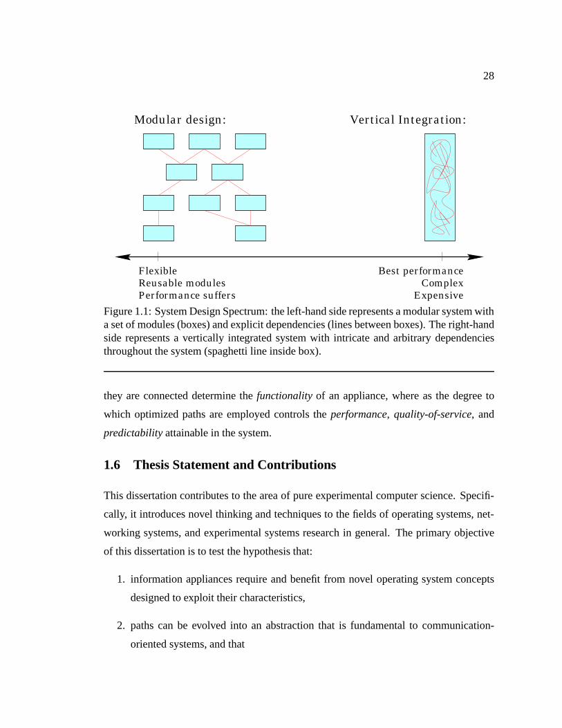
design spectrum illustrated in Figure 1.1. With the addition of paths, it becomes possible
to pick intermediate points in this spectrum: those parts of a system that are not perfor-
mance critical can be realized in a purely modular fashion, whereas performance critical
parts can be realized as optimized paths, giving performance close to that of a vertically
integrated system, but keeping cost and complexity down as only performance sensitive
parts need to be verticalized. Furthermore, with a well-designed path architecture, it
should be possible to carry out this verticalization in a structured and mostly automatic
fashion. Ideally, a system designer could specify in a declarative manner what parts of the
system are performance critical, and the path infrastructure would use this specification to
automatically translate modular code into an optimized path implementation. If the criti-
cal path has particular resource-management needs, such as a specific quality-of-service
requirement, the same declarative specification could be used to associate appropriate
resource-management policies with the path.
The degree to which this ideal case can be achieved will of course vary from appliance
to appliance and also depends on the quality of the tools that are available in the path
infrastructure. Realistically, a system with paths will always require slightly more effort to
build than a purely modular system and is unlikely to completely reach the performance or
resource-management potential of a fully vertically integrated system. But paths provide
the ability to start out quickly with an almost purely modular system and then optimize
performance for the parts that warrant the extra effort. In this sense, paths provide an
additional degree of freedom: the set of modules in a system and the manner in which
28
Vertical Integration:
Best performance
ExpensiveComplex
Modular design:
Flexible
Performance suffersReusable modules
Figure 1.1: System Design Spectrum: the left-hand side represents a modular system witha set of modules (boxes) and explicit dependencies (lines between boxes). The right-handside represents a vertically integrated system with intricate and arbitrary dependenciesthroughout the system (spaghetti line inside box).
they are connected determine thefunctionalityof an appliance, where as the degree to
which optimized paths are employed controls theperformance, quality-of-service, and
predictabilityattainable in the system.
1.6 Thesis Statement and Contributions
This dissertation contributes to the area of pure experimental computer science. Specifi-
cally, it introduces novel thinking and techniques to the fields of operating systems, net-
working systems, and experimental systems research in general. The primary objective
of this dissertation is to test the hypothesis that:
1. information appliances require and benefit from novel operating system concepts
designed to exploit their characteristics,
2. paths can be evolved into an abstraction that is fundamental to communication-
oriented systems, and that
29
3. a path abstraction can be defined that is both useful and general enough to build any
information appliance.
It should be noted that it is not possible to formally prove the correctness or falsehood
of this hypothesis. Instead, this dissertation is limited to providing, hopefully strong,
evidence for or against its validity. It does so by introducing a new operating system,
called Scout, and two Scout-based demonstrations.
Scout is designed specifically for information appliances and has been implemented
from ground up to avoid inappropriate concessions to or influences from traditional,
computation-oriented systems. Founded on a modular infrastructure that can cope well
with the diversity of information appliances, Scout provides a fertile ground for novel
solutions.
Chapters 2 and 3 present the Scout architecture. Chapter 2 begins with developing
a path model from first principles. As part of this development, many design-rationales
and trade-offs are exposed and discussed. With the path-model articulated, Chapter 3
proceeds to outline the overall architecture: Scout is modular to provide the layering
abstractions needed to cope with the diversity of information appliance. This modular
foundation is complemented by a concrete path architecture as a means to go beyond the
limits of purely modular systems. In particular, the use of paths in Scout enables it to
achieve better performance and better resource management than has been possible in the
past. The chapter also introduces a packet-classification scheme that is modular, has low
overhead, and avoids duplication of work.
After establishing the Scout architecture, Chapter 4 is a first evaluation that involves
studying a networking subsystem employing TCP/IP and remote-procedure call (RPC)
stacks. While not an appliances in and of itself, the communication-oriented nature of
appliances implies that the networking subsystem will be an essential aspect of many
appliances. Understanding this subsystem with respect to its behavior and its suitability
towards path-based optimizations is thus both important and interesting. Consequently,
the chapter presents a detailed analysis of the performance and behavior of the TCP/IP
stack when running on a modern 64-bit RISC architecture. Results for Scout are con-
trasted with those for a traditional, DEC UNIX based implementation. After establishing
30
the performance base-line, three path-based techniques are proposed and their effective-
ness evaluated. A fourth, compiler-based technique aimed at improving the predictability
of network processing is studied as well. All four techniques were applied to both the
TCP/IP and RPC stacks so as to provide insight into how they behave on networking
stacks with radically different design and implementation strategies. The three major
contributions from this study are that:
1. when processing small, latency-sensitive packets, the memory system can be the
primary bottleneck on a modern RISC machine,
2. the three path-techniques resulted in significant performance improvements, and
3. the fourth technique works in principle, but did not measurably affect performance
or predictability.
The first result is surprising: while it has long been known that the memory system is a
primary bottleneck for large, throughput-sensitive packets, it was generally assumed that
latency-sensitive processing is cache-friendly and thus bottlenecked by the CPU. This
study refutes that assumption at least for a large class of machines. The second result
implies that for the appliance under study, paths are useful to improving the performance
of latency sensitive processing. The third result is disappointing in the sense that the
compiler-based technique failed to improve predictability, but in analyzing the reasons
for its failure, a better understanding of the technique is obtained. With this improved
understanding, it is possible to enumerate the scenarios in which the technique might be
employed beneficially.
Chapter 5 introduces a demonstration appliance consisting of a networked TV that dis-
plays MPEG-encoded video streams [54, 67] through a windowing system on a graphics
frame-buffer. This appliance emphasizes the resource management aspects of paths. In
contrast to the networking study, almost all execution time is spent in the MPEG decoder,
hence the fact that modular code does not provide the best possible code-path hardly mat-
ters. Since video-display is a soft realtime application, proper resource management (in
particular proper CPU scheduling) is essential. Using paths and application-level framing
31
[16], the Scout appliance is able to run multiple video streams and non-realtime back-
ground loads all without causing unnecessary interference. Specifically, paths avoid pri-
ority inversion by allowing early segregation of work belonging to different streams, they
allow to schedule the entire processing of a video-packet according to the bottleneck
queue, and they provide the ability to account memory and CPU usage on a per-stream
basis. Chapter 6 presents a summary of the dissertation work, an outline of future research
directions, and some concluding remarks.
As a final remark, it is important to acknowledge that much of the inspiration and
motivation for this work derived from the vision of the future of information appliances.
In the end, it is this vision that provided the guiding framework. However, it is equally
important to understand that many of the results and techniques developed in this work
are not limited to the appliance context. For example, path-based code optimizations
are likely to be relevant to all modular and communication-intensive environments. The
results of the networking study provide insights into the behavior of communication sub-
systems that are interesting in their own right. Similarly, the considerations with respect
to resource managment are likely to be applicable to other multimedia-oriented systems.
Thus, even though appliances are used to motivate this dissertation, its impact is likely to
transcend beyond that specific environment.
32
CHAPTER 2
PATH ABSTRACTION
Our way is not soft grass,it’s a mountain path with lots of rocks.
But it goes upward, forward, toward the sun.
– Ruth Westheimer
This chapter establishes the vocabulary and fundamental concepts required to under-
stand the path-architecture of Scout. As motivated in the previous chapter, paths are
intended to facilitate tackling problems that are difficult or impossible to solve in purely
modular systems.
The systems research community has long harbored an intuitive notion of what a
path is. For example, it often refers to thefast paththrough a system [85, 73, 2, 112],
implying that the most commonly executed sequence of instructions have been optimized.
As another example, it sometimes talks about optimizing theend-to-end path[17, 15]
meaning the focus is on the global performance of the system (e.g., from I/O source to
sink), rather than on the local performance of a single component. As a final example,
it sometimes distinguishes between a system’scontrol pathand itsdata path, with the
former being more relevant to latency and the latter more concerned with throughput [27,
84]. But the wide-spread use of this term has so far not been translated into a well-
defined abstraction that could serve as a foundation of system design. The reason for
this is probably two-fold: first, the recognition that many path-like techniques could be
unified with an explicit path-abstraction has been missing in the past, and, second, even
once the usefulness of a unified path abstraction is recognized, it is non-trivial to define
and explain an abstraction that is, on the one hand, general enough to be widely applicable
and, on the other hand, specific enough to facilitate the various path-based optimizations
and resource management benefits.

33
2.1 Communication Network Analogy
The path abstraction proposed in this dissertation derives from an analogy between com-
munication networks and modular systems. Consider the example communication net-
work depicted in Figure 2.1. It consists of hosts at the edge of the network and of routers
in the interior of the network. The hosts and routers are connected by point-to-point links.
Router 2
Router 5
Host 2Host 3
Host 5
Host 6
Router 1
Router 3
Router 4
Router 6
Router 7
Router 8
Router 9
Router 10
Host 7Host 1
Host 4
Figure 2.1: Example Communication Network
How does a pair of hosts, say host 1 and 3, communicate in such a network? If we
assume a datagram-oriented network [100, 76], such as the Internet, then host 1 would
prepare a message, append the network address of host 3 to the message, and then inject
this datagram into the network by sending it to router 1. Router 1 would forward it to
router 2 which has a choice between router 3 and 10. Consulting its routing table, it might
decide that router 10 provides a better (e.g., shorter) path to host 3, so it may decide to

34
forward the datagram to router 10. This process continues through router 8 and 9 where
the datagram is eventually delivered to host 3.
Purely datagram-oriented networks work fine, but make it difficult to solve certain
tasks, such as transmitting data with quality-of-service guarantees such as a maximum
latency or a minimum throughput. Also, such networks require a routing decision per
router and per packet. If a sequence of packets is transmitted between a pair of hosts, this
results in a needlessly large overhead.
An alternative to the datagram style of communication is a connection-oriented style.
With a network of this type, if host 1 desires to communicate with host 3, it has to setup a
virtual circuit first. It can do so by sending a connection request message to the network
which causes the virtual circuit to be established (if possible). Once the virtual circuit
exists, host 1 can send data to host 3 simply by injecting messages into the virtual circuit—
no address information is required, since all the necessary routing information is already
present in the virtual circuit. This means that a routing decision has to be made only once
per router, independent of whether one or a million messages are eventually transmitted.
In this sense, a virtual circuit can be interpreted as a sequence offixed routing decisions.
Virtual circuits also make it relatively easy to support quality-of-service policies on a
per-connection basis. On the negative side, connection-oriented networks require explicit
connection setup and tear-down phases (both of which take time) and each virtual circuit
ties up some resources in each router (such as memory buffers).
Interestingly, the goals and features of virtual circuits are not unlike those desired for
paths. The extra routing overhead in a purely datagram-oriented network loosely corre-
sponds to extra call-overhead in a purely modular system. Similarly, datagram-oriented
networks and purely modular systems have difficulty providing quality-of-service guaran-
tees for the same reason: data is processed independently, without regards to the context
in which the data appears. Indeed, a modular system can be viewed quite naturally as a
network: Figure 2.2 illustrates a modular system (on a single host) that has a structure that
is isomorphic to the communication network shown in Figure 2.1. In Figure 2.2, instead
of hosts and routers there are modules. The function of these modules is summarized in
Table 2.1. One can see that at the edge of the network are modules that represent devices.
35
UFS
FDDI
MPEG
VFS MFLOW
NFS
RPC
UDP
IP
ATM
ETH
BCACHE
SCSI
KBD
MOUSE
DISPLAY
WiMP
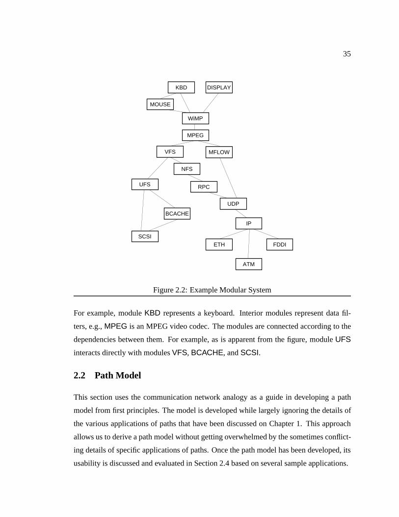
Figure 2.2: Example Modular System
For example, moduleKBD represents a keyboard. Interior modules represent data fil-
ters, e.g.,MPEG is an MPEG video codec. The modules are connected according to the
dependencies between them. For example, as is apparent from the figure, moduleUFS
interacts directly with modulesVFS, BCACHE, andSCSI.
2.2 Path Model
This section uses the communication network analogy as a guide in developing a path
model from first principles. The model is developed while largely ignoring the details of
the various applications of paths that have been discussed on Chapter 1. This approach
allows us to derive a path model without getting overwhelmed by the sometimes conflict-
ing details of specific applications of paths. Once the path model has been developed, its
usability is discussed and evaluated in Section 2.4 based on several sample applications.

36
Module: Description: Module: Description:KBD Keyboard driver MOUSE Mouse driverDISPLAY Graphics adapter driver WiMP Window managerMPEG MPEG codec VFS Virtual File SystemUFS UNIX File System BCACHE Buffer cacheSCSI SCSI driver MFLOW Multimedia flowcontrolNFS Network File System RPC Remote Procedure CallUDP User Datagram Protocol IP Internet ProtocolETH Ethernet driver ATM ATM driverFDDI FDDI driver
Table 2.1: Module Descriptions
2.2.1 Basic Path
Abstractly, a virtual circuit is a dataflow between two end-points. Thus, to a first approx-
imation, we can model a path as a dataflow that starts at a source device and ends at a
destination device. Since, respectively, the arrival and departure rates at the source and
destination device may not always match with the rate at which data is processed by the
path, the input and output devices are decoupled from the path by an input and output
queue. These queues loosely correspond to the socket queues of a virtual circuit.
For paths to be general, arbitrary processing must be supported as part of moving data
from the input to the output queue of a path. For example, if a path is used to receive a file
on an Ethernet network adapter and save it to a disk, then the processing might involve
TCP/IP and FTP protocol processing, as well as file system and SCSI related processing
to save the file on disk. In essence, this processing would transform a sequence of network
packets into a sequence of SCSI disk blocks. This arbitrary processing can be represented
by a functiong. If the input data (message) ism, then the output data deposited in the
output queue isg(m). Note that this general processing in a path is in contrast to that of
virtual circuits, where the processing functiong is restricted tog(m) =m(ignoring packet
losses and/or corruptions).
The basic path as discussed so far is illustrated in Figure 2.3. Devices are represented
as circles; the path is shown in the center of the figure with its input and output queues,
and the processing functiong.

37
Deviceg(m)
Device
Figure 2.3: Simple Path
The input and output queues are needed to accommodate transients in the arrival and
departure rates at the devices. However, the existence of those queues also implies that
there is flexibility (within certain bounds) in choosing the time at which a data-item is
moved from the path’s input queue to its output queue. That is, the time at whichg(m)
is evaluated is under explicit control of apath scheduler. Path scheduling loosely cor-
responds to the queue service discipline used in the routers that are crossed by a virtual
circuit.
Note that there is no one-to-one correspondence between paths and device-pairs. The
same device-pair can be connected by zero, one, or several paths. Using multiple paths
between the same device-pair may be sensible since either theg(m) or the scheduler may
differ between the paths.
2.2.2 Path Processing
As alluded to earlier, the processing functiong of a path can be arbitrarily complex. The
question of what exactly determinesg is best discussed with an example. Figure 2.4
repeats the modular system from Figure 2.2 but also shows a sample path as a bold line
starting at moduleFDDI, passing throughIP, UDP, MFLOW, MPEG, WiMP, and finally
arriving atDISPLAY (for simplicity, the path queues are not shown).
Presumably, each module processes data in a well-defined manner. For example, when
receiving input datam, moduleIP might apply standard IP processing. This would result
in output datagIP(m) which is the input data with the IP header stripped off. If we as-
sume similar partial processing functions can be defined for the other modules along the
path, then the processing that occurs along the path is equivalent to the composite of the

38
UFS
FDDI
MPEG
VFS MFLOW
NFS
RPC
UDP
IP
ATM
ETH
BCACHE
SCSI
KBD
MOUSE
DISPLAY
WiMP
Figure 2.4: Example Path in Modular System
application of the partial functions along the path:
g(m) = gDISPLAY(gWiMP(gMPEG(gMFLOW(gUDP(gIP(gFDDI(m)))))))
Note that the right-hand side corresponds exactly to what would happen in a purely mod-
ular system without paths. An advantage of paths is that the sequence of partial functions
is known and fixed once the path has been created. Using a semicolon (;) as the functional
infix operator denoting function composition [66], the path processing functiong can be
expressed as:
g= gFDDI;gIP;gUDP;gMFLOW;gMPEG;gWiMP;gDISPLAY
This concisely demonstrates one of the fundamental benefits of paths: they make it pos-
sible to expressg independent of the input datam. Among other things, this enables

39
optimizingg by reducing or simplifying the functional composite. For example, suppose
g consists of the compositiong0;g1;g2;g3. If it turns out thatg2 is the inverse of func-
tion g1, theng can be reduced tog0;g3.1 In general,g can be partially evaluated. If, for
example, one partial function depends on a part of the input data that has been added by
another partial function and that part is constant, then it may be possible to significantly
simplify the partial function that depends on this constant.
Note that our functional approach to defining a path’s semantics should not be mis-
taken to imply a particular implementation. It is certainly possible to realize the partial
processing functions as individual procedures in a programming language such as C, but
it would be equally legitimate to construct a path from a sequence of basic blocks, for
example.
2.2.3 Path Creation
A critical missing piece of the path model defined so far is how and when paths are
created. In many cases it is beneficial to exploit information that is available at runtime
only. For this reason, paths need to be created and destroyed dynamically at runtime. For
example, to distinguish between a video stream requiring realtime service and a video
stream requiring best-effort service only, it is typically necessary to take some runtime
information into account to be able to distinguish the two. If the video streams arrive over
the network, then the port-number of the corresponding network connections may furnish
this information.
The issue of how to create a path is rather interesting. There are two possible ap-
proaches:
1. paths are pre-specified (externally), or
2. paths are created (discovered) incrementally.
1This example is more practical than it may seem at first glance: oftentimes, a network connection islocal, meaning that the source and destination communicate through a loop-back device. Since the networkprotocol processing above the loop-back layer will cancel out, that protocol processing can, at least inprinciple, be removed from the path processing.
40
This division corresponds to the two sources of information that influence path creation:
global (system-wide) and local (module-specific). Considering that a primary goal of
paths is to exploit global information, it may seem like pre-specifying paths is the right
solution. In such a case, the system would provide a table that translate the properties of
the desired path into a sequence of modules that the path needs to traverse to satisfy these
properties. Consider the example system shown in Figure 2.4. In this system, there could
be a mapping that says that a path to display MPEG-encoded video on a graphics display
must start at moduleFDDI, go throughIP etc., and stops at moduleDISPLAY. In other
words, the mapping would specify the path shown as the bold line in the figure.
Unfortunately, there are serious problems realizing this approach in practice. Pre-
specifying a path often requires detailed knowledge of the internal workings of the mod-
ules encountered along a path. For example, whether the path in Figure 2.4 should go
from IP to FDDI or to ATM will typically depend on the host that is sending the video
and the routing information that is managed by the IP protocol. It certainly is imaginable
to embed such detailed knowledge in the part of the system that would manage paths, but
it is our contention that a much better solution is to follow the second approach, i.e., to
create paths incrementally. With this approach, IP itself can make the decision whether
or not the path should extend toATM or FDDI.
Of course, when creating paths incrementally, there is the problem that path optimiza-
tions that depend on knowing the full path cannot be implemented this way. For this
reason, incremental path creation must (in general) be followed by a second phase that
takes the incrementally created path and transforms it into a globally optimized version.
With these considerations in mind, we can now explain the path creation process in
the proposed path model. When creating a path, it is first necessary to describe the kind
of path that is desired. This description is in the form of name/value pairs. These pairs
express information about the path that is guaranteed to remain true throughout the life-
time of the path. In other words, with respect to the lifetime of the path, these name/value
pairs expressinvariants. In general, the more invariants are specified for a path, the better
the quality of the path. This can be understood intuitively since we would expect that the
41
more is known about a path, the easier it should be to create a well-optimized path.
Given a set of invariants, path creation is initiated at the module that is to form one end
of the path. This module uses the invariants to make arouting decision, that is, a decision
as to which module a path with the specified invariants must traverse next. Path creation
is then forwarded to that next module. This process repeats itself until either there is no
next module (i.e., the edge of the module graph has been reached) or until a module is
reached that, based on the specified invariants, cannot make a definite routing decision.
As part of making a routing decision, a module is free to update the invariants since new
invariants may become available in that module or old invariants may be invalid beyond
that module. Note that this does not contradict the requirement that invariants must hold
true for the lifetime of the path. It simply means that there can be invariants that hold true
only for a certain portion of a path.
2.2.3.1 Short Paths
An artifact of creating paths incrementally is that if the specified invariants are weak, the
created path may be short. For example, with the module graph shown in Figure 2.4,
UDP might create a path throughIP specifying thatany remote host is allowed to send
packets to this path. In such a case,IP could not make a unique routing decision because
packets could arrive throughETH, ATM, or FDDI. The resulting path would be short as
it would go fromUDP to IP only.
In the path model, paths therefore cannot be restricted to connecting device pairs.
Instead, a path may connect any pair of modules. What are the implications of this? When
a path is created, the creator expects a certain service from that path. That service must
be rendered independent of whether the path happens to be short or long, although the
quality or efficiency with which the service can be rendered may certainly be affected. In
the previous example,IP would be responsible to ensure that packets for the shortUDP-
to-IP path are received independent of the remote host and it would also be responsible
to forward such packets to theUDP-to-IP path. In other words, when a path terminates
at a certain module, it is the responsibility of that module to ensure that data arriving on
this path is continued to be processed appropriately. If the module is an interior module,

42
this typically means that the module must make adynamicrouting decision that may lead
to the data being forwarded to another (possibly also short) path. This case is illustrated
in Figure 2.5. It depicts an interior module with a path that ends at this module and two
paths that start at the module. When data arrives from the path above the module, it must
make a dynamic routing decision to determined whether the data needs to be forwarded
to the path at the lower left or the path at the lower right.
?
Figure 2.5: Dynamic Routing Decision
In the extreme case, a path may be so short that it simply connects a pair of neigh-
boring modules. Of course, such degenerate paths do not help in avoiding the problems
of purely modular systems, but the flip side of this coin is that the path model allows
us to approximate a purely modular system with little extra complexity. In other words,
for applications that are not performance sensitive and place no stringent demands on
the quality of resource management they receive, it is possible to use short paths. This
property also allows building prototypes quickly and optimize performance and behavior
later, when the system is better understood.
2.2.3.2 Extending Paths
One difficulty that remains with the previously described path creation scheme is that it
forces path creation to start at the end of a path. This can be illustrated easily in our run-

43
ning example from Figure 2.4. Let us consider how a user might specify the playback of
a video in the illustrated system. Most likely, the user would issue a command instruct-
ing playing the video located at, e.g.,http://www.mpeg1.de/movies/maze.mpg on, for
example, the graphics display of the machine (as opposed to saving the video to a local
disk). Thus, one end of the path is implicitly determined by the address of the video server
(http://www.mpeg1.de/) and the other end by the specification of the output device (the
graphics display). The entity creating the path can and should specify the video source
and output devices as path invariants, but it should not have to know how to translate those
names into the modules that will terminate the path.
UFS
FDDI
MPEG
VFS MFLOW
NFS
RPC
UDP
IP
ATM
ETH
BCACHE
SCSI
KBD
MOUSE
DISPLAY
pathCreate(output=DISPLAY)
WiMP
UFS
FDDI
MPEG
VFS MFLOW
NFS
RPC
UDP
IP
ATM
ETH
BCACHE
SCSI
KBD
MOUSE
DISPLAY
pathExtend(input=http://www...)
WiMP
Figure 2.6: Path Creation UsingpathExtend
An elegant solution is to split up path creation: when a command is received to dis-
play an MPEG encoded video, it is clearly necessary that the path contains theMPEG
module.2 Hence, path creation could start there and, in a first step, a (short) path from
MPEG to the output device (DISPLAY) could be created. Then the path can beextended
from MPEG to the module that provides the video source (FDDI, in our example). The
2One possible mechanism to determine the starting module will be presented later in Chapter 5.
44
first step can already by realized using the path creation operation with an invariant speci-
fying the output device (see left hand side of Figure 2.6). For the second step, we need to
add to the model a path extension operation. This operation works in the exact same way
as path creation, except that, rather than being invoked on a module, it is invoked on the
end of an existing path. The invariants specified for the path extension will of course be
different from those specified for the path creation operation (though some may remain
the same). In our example, the path extension operation would be invoked with an invari-
ant specifying the URL of the video to be displayed. This is illustrated in the right hand
side of Figure 2.6.
In such a scenario, there is not much point in applying global path optimizations
right after creating a path that will be extended. Doing so would not cause incorrect
behavior but it would most likely be wasteful. For this reason, it is best to keep global
path optimization separate from path creation and extension. This also makes it possible
to skip global path optimizations for paths that are not worth the added time or memory
required to build an optimized path.
An alternative to path extension would be to first create two independent paths which
are then combined at their common endpoint (at moduleMPEG, in the example). This
solution was rejected since it would either necessitate transforming the identity of one
path into that of the other or changing the path model to allow a hierarchical structure
that can contain sub-paths. A change of identity might also necessitate moving resources
reserved for one path to the other path, which is complex at best and impossible at worst.
Hierarchical paths are undesirable as well since that would sacrifice the simple structure of
paths. Both solutions would also suffer from the problem that a path combining operator
would allow creation of nonsensical paths, such as circular paths. The path extension
operator defined above suffers from none of these problems.
2.2.3.3 Optimization Phase
As explained earlier, paths are created incrementally, which results in maximum-length,
though not necessarily optimal, paths. To obtain optimal paths, path transformations
(optimizations) need to be applied in a second phase of path creation.

45
Abstractly, optimizing a path involves transformation rules which consist ofhguard,
transformationi pairs. If Path denotes the set of all possible paths, then the type signa-
tures of the guard and the transformation functions are:
guard : Path! Boolean
transformation : Path! Path
The idea of a transformation rule is that given a pathp, guard(p) is first evaluated. If
true, p is replaced byp0 transformation(p), otherwise,p0 p (i.e., the path is used
unmodified). Since a path represents a maximum length sequence of modules and all
other information pertinent to the operation of the path, transformation rules have as much
context available as is possible. The quality of path optimization is therefore limited only
by how long the path is (some paths may be shorter than one would like ideally) and
by the quality of the transformation itself. Since it is applied at runtime, the amount of
time available to the transformation is certainly bounded and in most cases limited to
relatively short time-spans. Since the transformation needs to operate within a limited
time budget, it is often advantageous to precompute expensive parts of the transformation
off-line. Examples of such transformations will be discussed in Chapter 4.
A real system is expected to employ many path transformation rules. When multiple
rules exist, they are applied repeatedly and in no particular order. The optimization phase
stops when no rule can be found whose guard evaluates to true. Note that this is a con-
ceptual model. An actual implementation would likely attempt to exploit the structure
that may be present in the guards of the rules. For example, rather than evaluating guards
linearly, it may be possible to build a decision tree that reduces the number of guards that
need to be checked for a newly created path.
2.2.3.4 Invariants
Invariants form the backbone of path creation and it is therefore worthwhile to discuss
them in more detail. First, observe that invariants are essentially the vehicle that allows
communicating information (knowledge) between modules. As such, the meaning of each
name of an invariant must be universally agreed upon. Of course, each module does not

46
have to know about all possible invariants, but it must be assured that if it uses an invariant
of a given name, then every other module in the system must understand that invariant in
the same way.
One question that arises is what a module should do if it encounters an invariant whose
meaning it does not understand. It could either remove that invariant when passing on the
path creation request, or it could leave it in the invariant set. The former is guaranteed to
be safe, since it simply means that the path being constructed may end up being shorter
than ideally would be the case. However, there are cases of important invariants that are
known to be pervasive throughout the path. In such a case, it is desirable to tunnel such
invariants through modules that do not understand their meaning. For this reason, two
classes of invariants are defined:limited invariants that are removed when encountered by
a module that does not understand them, andpervasiveinvariants that are passed through
such modules unchanged. Finer-grained classifications are of course imaginable, but our
experience is that this two-class scheme works well in practice.
At this point it may be helpful to discuss some concrete examples of invariants. Since
invariants affect routing decisions, any kind of address information is typically specified
as an invariant. For example, the path name of a datafile could be specified by an invariant
namedFILENAME. Similarly, the network address of a remote host that one wants to
communicate with could be specified using an invariant calledPARTICIPANT. Another
kind of invariant that is often useful provides information about the data that will traverse
the path. For example, if possible, it is often useful to specify a lower and upper bound
on the size of a single data-item. Such an invariant obviously belongs to the class of
limited invariants, since a module that does not understand this invariant may still change
the size of any data-item passing through it. Thus, if the invariant were not limited, the
module might unknowingly cause it to be violated. Data access patterns can also often
be exploited, so specifying them as invariants is useful as well. For example, if a file is
accessed in a strictly sequential fashion and its size is known, a cache module might be
able to tell whether it is likely to be worthwhile to cache the file or whether it is better to
leave the file uncached so other, already cached data does not get displaced. An example
of a pervasive invariant may be one that indicates that the created path is intended to be

47
used in a realtime environment. This property will be true independent of whether an
intermediate module understands it or not.
This discussion should make it clear that there is a dependency between the invariants
that can be usefully exploited and the invariants that can be specified. If the creator
of a path does not know about the existence of some type of invariant, then it clearly
cannot specify that invariant, even if it happens to be true for the path. Conversely, if
a module does not know about the existence of an invariant, it cannot exploit it, even
though it might be easy to do so if it had known about the invariant. Since it is not
really possible to solve this dilemma perfectly, an iterative process seems appropriate. As
will be discussed later on, Scout defines a (small) initial set of invariant names that are
considered useful in exploiting various path benefits. As experience is collected and new
means to exploit paths are invented, this set is bound to grow. This is unfortunate since it
may require changing existing code to fully exploit new invariants (this is never required
for correctness), but the hope is of course that this process will eventually converge on a
manageable number and stable set of invariants.
2.2.3.5 Who Creates Paths?
The final question that needs to be answered with respect to path creation is: what is
the entity that creates paths? In the path model we are proposing, this works as follows.
When a system starts up, the constituent modules are initialized in some order. As part
of its initialization, a module may elect to create one or more initial paths. After module
initialization is complete, new paths may be created as a side effect of execution of other,
already existing, paths. In other words, once the system is initialized, paths create paths.
For example, a networking service would typically create a path for its well-known
address while its module is being initialized. Then, whenever it receives a new connection
request, the service may elect to create a new path to handle the new connection. Sim-
ilarly, a command-line interpreter is likely to create a path to the input device (e.g., the
keyboard) during initialization. New paths are then created as a side-effect of handling
key-strokes.
48
2.2.4 Generalized Paths
As defined so far, paths are simple and highly predictable: a data-item arrives at the
input queue, the path is scheduled for execution, and the transformed data is deposited in
the output queue. While this simplicity is ideal for the purpose of optimization, it also
severely limits the usefulness of paths. It is thus necessary to extend paths to make them
more widely applicable. The challenge is in doing this in a way that does not destroy the
properties that make the path abstraction attractive in the first place.
2.2.4.1 Directionality
Basic paths are essentially unidirectional dataflows. To be able to communicate in both
directions (source to destination and vice versa), it would therefore be necessary to create
two paths. This is a workable solution in many cases, but is not sufficient in others. In
particular, for request-response like applications, it is typically necessary to guarantee
that a reply returns along the exact same path through which the corresponding request
arrived. Just as important, from the point of a user of a path, it is more convenient if the
path used to send a request is also the one that will yield the reply.
In other cases, the two dataflow directions are mutually dependent. For example, in
networking protocols it is often convenient and more efficient to piggy-back information
about the state of the receiver on packets produced by the sender. If the two directions
were handled by separate paths, it would be difficult, if not impossible, to communicate
the necessary information from the receiver path to the sender path. As a final argument,
consider resource consumption. Unidirectional paths consume less resources (memory,
primarily) in a system where most paths are unidirectional, but they would use more
resources in a system where many path pairs are needed to emulate bidirectional path.
This argues neither for nor against bidirectional paths. However, it seems much easier to
optimize bidirectional paths that are used in a unidirectional manner only than it would be
to optimize a path-pair, since the latter consists of two independent entities. Based on this
slight advantage and the other considerations that suggest bidirectional paths, it appears
that extending the path model to support bidirectional dataflows is appropriate.

49
To support bidirectional dataflows, the path model can be extended as follows. Each
extended path has four queues—an input and an output queue for each of the two di-
rections. Also, the path functiong is extended to take a second argumentd that gives
the direction (forward or backward) in which the path should be traversed. The module
specific partial processing functions are extended analogously.
The reason the two directions are calledforward andbackwardis that a path may
wind its way up and down through a module graph. Thus, terms commonly used in
layered systems, such asaboveandbelowor top andbottomare meaningless for paths.
Forward and backward are more neutral terms but it is important to understand that these
are just labels—the two directions are completely symmetric as far as the path model is
concerned.
2.2.4.2 Complex Processing
So far, the path model assumes that the path processing iswork conservingin the sense
that for every input data-item, there is exactly one output data-item.3 This is limiting
since it means that certain common operations cannot be accommodated. For example, it
is not unusual for a module to consume multiple input data-items before producing output
data. Conversely, some modules may respond with multiple output data-items for each
input item. Finally, in some cases a module may generate a data-item spontaneously, e.g.,
in response to the expiration of an internal timeout.
For these reasons, it is necessary to loosen the evaluation rule for paths as follows.
Suppose path processing consists of the composition of functionsg1; : : : ;gn. With the
new evaluation rule, a data-item may be injected at any one of these sub-functions and
the invocation ofgi may result either ingi�1 or in gi+1 being invoked. That is, these
sub-functions can be invoked in any order, subject to the restriction that only neighboring
functions are invoked, or that the data be enqueued at an output queue. Note that in
the extreme, this allows for a data-item to loop endlessly inside a path. Of course, few,
3Work conservingis often used in the context of queueing theory, but that use is only indirectly relatedto the way we employ the term here. The commonality is that in both contexts, the term means that noadditional work is created inside a system itself.

50
if any, useful paths would do this. However, the fact that the path model allows for
endless looping is analogous to universal (Turing-complete) programming languages [24]
which must allow for the possibility of infinite looping even though most useful programs
terminate in a finite amount of time.
2.3 Summary and Discussion
In summary, a path is created by invoking a create operation on a module and specifying
a set of invariants. The invariants describe the properties of the desired path, and are
used to determine a next module that must be traversed by data traveling along the path.
The process of determining the next module is calledmaking a routing decision, since
it affects the route that the path takes through the module graph of the system. Routing
decisions are made repeatedly until the path reaches its maximum length. This occurs
either when the invariants are no longer strong enough to make a unique routing decision
or when the edge of the module graph is reached. Each module that is traversed by a path
supplies a partial processing functiongi that implements the semantics of the module for
the path under construction. A detailed view of a path that traverses three modules is
shown in Figure 2.7. In addition to path creation, there is a path extension operation that
allows creating paths when only an interior instead of an endpoint module of the path is
known.
Module Moduleg1 g2 g3
Figure 2.7: Example Path
Once a path has been created, the path optimization operation can be invoked on it.
During this phase, transformation rules are applied repeatedly until none of the rules can
be applied any longer. This allows to exploit optimizations that require the full context of
the path for proper operation.

51
Path execution is decoupled from the data arrival and departure processes at the end-
point modules by four queues. For each of the two directions of dataflow, there is an
input and an output queue. Typically, path execution involves dequeuing data from an
input queue and evaluating thegi functions in sequence until the other end of the path is
reached. However, for generality, a message may get absorbed in the middle of a path, or
be turned around, or a new message may be created spontaneously inside a path.
2.3.1 Policy Issues
The path model defines amechanismand avoids policy issues to the degree possible.
Nevertheless, it is necessary to discuss the policy issues that arise as a result of this model.
Paths create a two-dimensional policy space. One dimension could be labelledlength
and the otherwidth. The length of a path is related to how many modules it crosses. The
width of a path is related to how specialized a path is. A highly specialized path would
be considered narrow, whereas a general path would be considered wide. For example,
a wide path may process data from many different remote hosts, whereas a narrow path
may be tailored for the processing of data from one particular host.
It might seem that it is always desirable to create long and narrow paths. A long path
has much of the global context available that is needed to achieve good performance. And
a narrow path is specialized which further simplifies the task of creating a well-optimized
path. But in reality, paths have costs: it takes both time and space to create them and
having many paths means that each path will be used less often, meaning that there is less
locality of use. Thus, the choice of whether a path should be long and/or narrow depends
completely on the intended use of the path. Tasks that are not performance critical are
usually best realized with short and wide paths, whereas performance critical tasks would
most likely be realized with long, and possibly narrow, paths.
Since the path model is claimed to be policy-free, what parts of a path-based system
do implement policy? Ultimately, it is the invariants that determine the route of a path and
its width. Thus the creator of a path realizes policy by specifying more or fewer invariants.
Similarly, a module making a routing decision is affecting policy by choosing to either
honor or ignore a specified invariant. This means that path policy is not implemented in

52
a well-defined, separate entity but instead is scattered throughout the various modules.
This is not surprising since the width and length of a path cannot be specified without
taking into account the semantics of each module that is traversed by the path. Of course,
it would be possible to define an invariant that specifies the desired length of a path.
Limiting a path’s length is always possible, but forcing a minimum length is not, since
an intermediate module may not be able to make a unique routing decision based on the
specified invariants.
2.3.2 Intuitive Models
When reasoning about paths, it is often helpful to focus on one of the several aspects that
make up a path. As a result, paths have many faces. Depending on the context in which
they are being discussed or used, a path can be viewed as:
� a bidirectional dataflow,
� a processing pipe-line.
� a path of execution,
� a resource account, or
� a locus of identity.
When dealing with processing efficiency concerns, one of the first three views is typically
employed, whereas for resource management problems, the latter two views are more
helpful. Note that neither view is the correct one since no single view adequately captures
all of the various aspects of paths.
2.3.3 Limitations
A limitation of the proposed path model is that it does not directly support any form
of fan-in/fan-out or multicasting, loosely speaking. In the path model, this would be
approximated either by several point-to-point paths or by a single path that covers the

53
Figure 2.8: Approximating Fan-In/Fan-Out With Multiple Paths
common parts and then several small paths that cover the independent parts. The former
solution is illustrated in the left hand side of Figure 2.8, the latter in the right hand side.
The absence of direct support for fan-in or fan-out is a limitation but at the same time a
feature of paths. With multiple input or output points, code optimization techniques such
as ILP could not always be realized because at path branching points, it would not be
clear what module would be entered next. Similarly, for resource management it is often
useful to know what the exact source or the destination of a data-item is. With fan-in and
fan-out, this question could not be answered for all paths and would thus largely defeat
the purpose of paths.
2.4 Applications
With the path model in place, it is time to discuss a few specific applications of paths.
The goal of this section is provide a more concrete idea of how paths are used, and at the
same time, argue that many ideas and techniques that have been implemented in an ad hoc
fashion in the past, can be realized in a straight-forward manner using paths. In that sense,
the path model is believed to be a unifying abstraction. However, this discussion should
not be taken to mean that paths are limited to the specific examples given below. Rather,
the path model should be considered a framework that simplifies realizing the specific
examples and that should enable development of other path-based techniques that have
yet to be discovered.
54
Broadly speaking, paths can provide two kinds of benefits: (1) they can improve code
quality, and (2) they can improve resource management. The two kinds of benefits are
typically independent, and hence, additive.
2.4.1 Code Optimizations
Paths can help improving the code quality by virtue of the fact that they allow partial
evaluation of the path processing function, as explained in Section 2.2. A few specific
examples follow below.
2.4.1.1 Code Synthesis
Pu et al. propose a runtime code synthesis technique that involves collapsing layers to
avoid the overhead that is typically caused by crossing module or layer boundaries [86].
The technique allows further optimization of the collapsed code through factoring of in-
variants and elimination of data copying. For this technique to be applicable, it is neces-
sary to know the invariants that are true for the code-path through the system that is to be
optimized. In addition, it is necessary to know the sequence of functions that need to be
collapsed. The path model proposed in this chapter provides both kinds of information
and thus makes this technique readily applicable.
2.4.1.2 Integrated Layer Processing
For this technique (see Section 1.4.1.2) to be applicable, it is necessary to know the se-
quence of data-processing steps that a network packet will follow. The path model can
trivially support this kind of application since the sequence of modules being traversed
is known and fixed for the lifetime of a path. A combination of the language-based ILP
approach presented by Abbott and Peterson [1] and paths should therefore enable making
ILP a truly practical technique.

55
2.4.1.3 PathIDs
The PathID approach (see Section 1.4.1.3) consists of a combination of two techniques:
a mechanism to efficiently find the path for a network packet and a highly sophisticated
partial evaluator—namely a human being. The issue of how paths are located is not part of
the path model proper, but as will be discussed in Section 3.4, a solution to this problem is
needed in any path-based system, and as such, the PathID technique is applicable. More
interesting to the path model is the way the hand-optimized (partially evaluated) code
is employed. This could be done by specifying a path transformation rule that matches
the sequence of network protocols that were manually optimized. If a path contains a
sequence for which hand-optimized code exists, the old (unoptimized) code in the path
can be replaced with this manually optimized version.
2.4.1.4 Single-Copy TCP/IP
As far as the path model is concerned, the single-copy TCP/IP technique discussed in
Section 1.4.1.4 is almost identical to PathIDs. Again, unoptimized code is replaced by
highly tuned, manually written code.
2.4.1.5 Summary
The four examples discussed above all depend on being able to associate optimized code
with a particular path. They all differ in what type of partial evaluation they apply, but
fundamentally they are all quite similar in that they exploit the linear structure that is
often present in the performance critical code. The defined path model therefore is ideally
suited for this kind of code-related optimizations.
2.4.2 Resource Management
The second kind of benefits that the path model affords is related to improved resource
management. A discussion of three applications that exploit this follows.
56
2.4.2.1 Fbufs
Fbufs [29] are a path-oriented buffer management mechanism designed to efficiently
move data across multiple modules that are in different protection domains. This tech-
nique depends on knowing the sequence of modules that will be traversed by a data-item.
In addition, it requires a provision for path-specific memory allocators. Both requirements
can be accommodated easily in the proposed path model.4
2.4.2.2 Migrating/Distributed Threads
Migrating (distributed) threads [19, 45, 37] address the issue of anonymity of processing
that often poses problems in modular systems. Typically, when data enters a new module,
information on whose behalf the data is being processed is lost. Since, in the path model,
all execution is in the context of paths, they can serve the same purpose as distributed
threads. In essence, this application uses paths as an account that can be charged for
resources (e.g., memory or CPU cycles) that are consumed as part of the data processing.
2.4.2.3 Segregation of Work
The dataflow view of paths is important when building systems that require offering dis-
tinct quality-of-service (QoS) to different data streams (applications). In a modular sys-
tem, lower layers often mix processing of different data streams. This multiplexing makes
it difficult to provide differentiated service. Paths force a segregation of work on a per-
path basis. Thus, as long as each service class is represented by a separate path, even
lower layer modules can easily distinguish between the needs of different streams and
provide service accordingly. For example, when processing data with a realtime con-
straint, the deadline by which the data needs to be processed could be associated with the
path. This makes the deadline accessible and visible to all modules along the path as well
as to the path scheduler itself.
4Note that the Scout implementation of the path model that will be presented in Chapter 3 does notsupport protection domains. But this does not mean that the path model could not be applied to systemswith multiple protection domains.

57
2.5 Related Work
At the surface, paths are similar to UNIX pipes [89] and Pilot streams [87]. While all three
have in common a linear sequence ofcomponents(processes in UNIX, Mesa modules in
Pilot, modules in the path model), neither pipes nor streams provide any global context to
the individual components. Neither do they attempt to optimize the code along a path. It
is also the case that UNIX pipes are more coarse-grain and unidirectional.
The system that is, at least terminology-wise, close to the proposed path model is
Da CaPo [40]. Da CaPo stands fordynamic configuration of protocolsand defines an
infrastructure for building multimedia protocols. It has an explicit notion of paths, but
there are important differences to our proposed path model at all levels. At lowest level,
Da CaPo paths are unidirectional and the partial processing functions have restricted se-
mantics (they are essentially non-blocking event-handlers). As a result, Da CaPo is not
universal or even powerful enough to accommodate all but the most basic tasks that arise
from network protocol processing. Another important difference is that path creation is
left completely to an externalconfiguration manager. As pointed out in Section 2.2.3,
this means that in any reasonably complex system, the configuration manager will be
burdened by detailed knowledge of the internal workings of particular modules. In con-
trast, the path model makes it easy to exploit both local and global information during
path creation. At a higher level, Da CaPo focuses completely onautomatically selecting
appropriate protocol functionality; performance and resource management appear to be
lesser issues to Da CaPo.
CORDS is a communication subsystem by the Open Group (formerly Open Software
Foundation) that is based on thex-kernel [49]. It employs a path abstraction that is based
on early work that lead to the path model proposed here. As such, paths as presented
in [105] are limited in several ways. First, they are applicable in the communication
subsystem only. Second, they do not admit path-oriented code optimizations as discussed
in Section 2.4.1. Third, they do not admit paths that are shorter than anticipated or desired.
Indeed, it is not clear whether CORDS would be able to detect and handle such cases. A
final, and arguably the most significant, difference is that in CORDS, paths are defined as
58
an add-on abstraction that is often in conflict with other abstractions (e.g., session objects
in thex-kernel). In contrast, the path model proposed here provides a unifying and general
path abstraction.
In addition to the above mentioned work, there is a wealth of research on mechanisms
that offer point-solutions to the more general problem of exploiting paths, both as a code
optimization and resource management framework. Examples of code, or fast-path op-
timizations include Synthesis [60], Synthetix [85], PathIDs [56], Protocol Accelerators
[107], and integrated layer processing [16, 1]. Examples in the second category include
processor capacity reserves [64], distributed/migrating threads [19, 37], and Rialto activ-
ities [52]. These related works do not attempt to define an explicit and universal path
abstraction, but are a source of interesting examples of how paths can be employed.
The work on Synthetix is also interesting in that it introduces the notion ofquasi-
invariants. Quasi-invariants are similar to invariants as discussed in Section 2.2.3.4 but
differ in that they may become invalid during the lifetime of a path. The idea behind
quasi-invariants is that, in some cases, invariants are likely to be true for a long time-span,
but there is a chance that they may become invalid at any point in time. Supporting quasi-
invariants enables exploiting such almost invariants and thus allow for more aggressive
optimization. They also introduce more complexity in the path model, since invalidation
of a quasi-invariant will require corrective actions. There is no reason to believe that the
proposed model could not be extended to accommodate quasi-invariants, but this avenue
of research has not been explored as part of this dissertation.

59
CHAPTER 3
SCOUT ARCHITECTURE
Nobody trips over mountains.It is the small pebble that causes you to stumble.
Pass all the pebbles in your path andyou will find you have crossed the mountain.
– Unknown
This chapter describes the most important aspects of the Scout architecture, which
includes its modular system, its path implementation, how it demultiplexes (classifies)
data onto paths, and its execution model. The goal of this chapter is to motivate and
discuss architectural issues of Scout that are interesting and novel. For a comprehensive
and detailed description of the various programming interfaces, the reader is referred to
the Scout manual [101].
3.1 Overview
Scout is an operating system designed for information appliances such as set-top boxes,
or file- and web-servers. It is implemented in C [57], founded on a modular structure
and built around the path abstraction which makes it suitable for the communication-
oriented nature of appliances. The current system supports both best-effort and soft re-
altime scheduling. It is optimized for the needs of appliances and, at present, does not
support multiple address spaces, protection domains, or shared-memory multiprocessors.
The reason for limiting the initial realization of Scout to simple uniprocessors is
twofold. First, we expect that many appliances will not require more than what is cur-
rently provided by Scout. This is a direct consequence of the characteristics of appliances:
they are specialized and often relatively small. Thus, shared memory multiprocessors and
multiple protection domains are unlikely to be a requirement of many appliances.
60
Second, simplifying the structure of Scout allows us to focus on the intrinsic issues of
communication-oriented systems. For example, it allows designing the path abstraction
without worrying about how well it would be supported by the protection mechanisms
of current hardware. This is a valid approach since it may be desirable and reasonable to
change current hardware abstractions in response to the needs of communication-oriented
systems. On the other hand, this approach bears the danger of conjuring up abstractions
that have no hope of ever being able to run efficiently in a more complex system. While
this danger exists, we have no reason to believe that this is the case for the Scout system
presented in this chapter. Indeed, as the system is developed, informal arguments are
presented as to why and how it could be extended to more complex environments.
With the above considerations in mind, it should be no surprise that conformance
with standard programming interfaces, such as POSIX [94], is not a primary goal of
Scout. An understanding of how existing interfaces support or interfere with the needs of
a communication-oriented system could be useful, but is a secondary issue. In contrast to
the internal programming interfaces, the external communication protocols are considered
a given. This is not to say that existing protocols are sufficient or that they could not be
improved upon, but it does mean that Scout must be capable of supporting existing, wide-
spread protocols such as the Internet’s TCP and IP protocols.
3.1.1 Scout Epochs
Before going into the details of Scout, it is useful to discuss the various epochs in a
Scout system that are illustrated in Figure 3.1. The first epoch occurs when individual
modules are implemented by a programmer. At a later time, the system designer decides
what kind of paths are likely to be important to system performance. For those, path
transformations can be implemented as described in Chapter 2. Once these are realized,
the desired functionality for a particular information appliance is chosen by selecting the
appropriate modules and connecting them into a module graph. At the same time, the
designer can also specify complete path transformation rules (i.e., pick the appropriate
path transformations and associate them with the proper guards). When this is all done,
the system (kernel) is built. All steps mentioned so far are considered to occur duringbuild

61
time. In contrast,runtimecovers all the steps that occur after the system has been booted
on the target machine. During that time, paths may be created, used, and destroyed.
build timeruntime
Early
Late
module implementation
path transformations
kernel build
path creation
path execution
module graph & transformation rules
Figure 3.1: Scout Development Timeline
3.2 Modularity
Modulesare the unit of program development in Scout. In the Scout implementation,
modules are actually calledrouters to encourage thinking of them as entities that route
data through the system and also to avoid the overloaded termmodule. The flip-side
of this convention is, of course, that the termrouter sometimes causes confusion when
speaking of Scout in the context of communication networks that employ conventional
network routers. Independent of the implementation, this dissertation continues to use
the termmodulefor the sake of consistency.
62
3.2.1 Module Granularity
The choice of the granularity of modules is important since modularity is not free of costs.
First, modularity often causes runtime overhead. Sometimes, the overhead is due to the
limited context that is available when building the modules. For example, the programmer
may not know in what context the module will be used and therefore is forced to imple-
ment the most general case, or independent compilation limits the context available to the
compiler’s optimizer, making it difficult to optimize across module boundaries. Second,
modularity implies the use of standardized interfaces. These interfaces ensure that a large
number of module pairs can be connected to form new and interesting systems. However,
adhering to these relatively strict and difficult-to-change interfaces forces implementing
modules in a way that is often suboptimal. For example, auxiliary data sometimes needs
to be packaged into abstract data types to communicate them across module boundaries.
Consequently, dividing up a system into the smallest possible modules is generally not a
good idea. On the other hand, the extreme case of not using modules at all is certainly not
ideal either since that would be equivalent to building a vertically integrated system.
Out of these considerations, a Scout module is expected to provide a well-defined
and independent functionality. Well-defined means that there usually is either a standard,
interface specification, or other existing practice that defines the exact functionality of a
module. Independent means that each single module should, by itself, provide a useful,
independent service. That is, the module should not depend on there being other specific
modules connected to it. While Scout does not enforce these rules, they are assumed in
the design. As a result, Scout works best when modules have an intermediate level of
granularity. Typical examples are modules that implement networking protocols, such
as IP, UDP, or TCP; modules that implement storage system components, such as VFS,
UFS, or SCSI; and modules that implement drivers for the various device types in the
system. Examples of modules that, for Scout, are likely too fine-grained include the
IP fragmentation algorithm, the MPEG inverse discrete cosine transform, or the UDP
checksumming algorithm.
Given that Scout claims to be able to avoid the disadvantages of modularity by using
63
paths, it may be surprising that it does not advocate modules of the smallest possible
granularity. The reason for this is two-fold. First, paths primarily address inefficiencies
due to limited optimization context. It is distinctly more difficult to automatically avoid
overhead that arises due to interface mismatches. Of course, it would be possible to
manually implement an optimized path that avoids interface mismatches, but whenever
possible, it is preferable that efficient paths be created automatically from the underlying
modules. Second, there is also a third cost to modularity: the act of decomposing a system
into modules takes time and consideration. If the resulting modules are so small that they
can be used in only one possible module configuration (i.e., they cannot be reused), then
nothing is gained. In other words, there is no advantage to going below a certain level of
granularity.
3.2.2 Module Structure
Abstractly, a Scout module implements a certain functionality and provides access to this
functionality throughservices. Each service provides access to one aspect of the module’s
functionality. For example, modules often provide filter-like functionality, which could
be realized by a pair of services: one service representing the filter’s input, the other the
filter’s output. However, the number of services provided is not limited to two, but is
determined by the module. In the degenerate case, a module might not have any services
at all, though such an isolated module would not be very interesting as it could not be
connected to any other module. More typically, modules provide on the order of two or
three services. The services in an module are assigned unique names to make it possible
to reference and distinguish them. Other than the requirement that the names are unique,
they can be arbitrary strings. Since services are accessed by other modules, they also have
a type associated that specifies the protocol (language) that the service uses to communi-
cate. The exact meaning of this type will be discussed later in this chapter. For now, it is
sufficient to know that each service has a name and type associated with it.
An example module is shown in Figure 3.2. The big box represents a run-length
compression filter [91]. The two nested boxes represent services:plain provides access
to the plain, uncompressed data andcompr provides access to the run-length compressed

64
plain:ByteStream
compr:ByteStream
RLCODEC
Figure 3.2: Module With Two Services
data. Both services are of typeByteStream . As shown in the figure, it is customary in
Scout to separate the service name from its type by a colon (a convention adopted from
Pascal-like languages [20]). SupposeByteStream represents a bidirectional stream of
data bytes. In this case, data sent into theplain service would be run-length encoded
and sent out through thecompr service. Conversely, data sent into thecompr service
would be run-length decoded and then passed on through theplain service. This is
the reason the module is calledRLCODEC: it provides both run-length encoding and
decoding functionality.
Concretely, a Scout module is implemented as a collection of C source files. Each
module is described by a so-calledspecfile that lists the names of the C source files that
belong to the module and the services that the module provides. The syntax for spec files
is shown below:module name f
files = ffilename , ... g;
service = f[<]name: type , ... g;
g
As indicated, a service name may optionally be preceded by a less-than marker (<).
This is used to constrain module-initialization order and is discussed in detail in Sec-
tion 3.2.3.2. For the run-length codec module in Figure 3.2, thespecfile might look as
shown here:module RLCODEC f
files = frl-encoder.c, rl-decoder.c, rlcodec.h g;
service = fplain:ByteStream, compr:ByteStream g;
g

65
The spec file completely defines a module: it specifies its functionality (semantics) by
listing the C files that belong to the module and it defines the external interface to the
module by listing the names and types of each service. Each modulem is expected to
export a global C function calledmCreate . This function is used to create a module at
runtime, as explained later in this section.
3.2.3 Module Graph
To form a complete system, individual modules need to be connected into a modulegraph.
A module graph consists of a collection of modules whose services are connected in a
(hopefully) meaningful manner. For example, to build a network-attached camera whose
video data should be run-length encoded before being sent out on the network, one could
use the module graph shown in Figure 3.3. In this graph,RLCODEC represents the
run-length codec introduced earlier in this chapter,CAMERA is the device driver for the
camera,MONITOR is a device driver for the small monitoring display of the camera,
andNETWORK is the module implementing network support (in reality, the networking
subsystem is likely to consist of multiple modules). Recall that aByteStream is a
bidirectional data streams, so in this simplistic example, commands that are sent from the
network to the camera would have to be run-length encoded as well.
In Scout, the module graph of a system is described by the fileconfig.graph .
This file consists of a list of module declarations, followed by a list of connections. The
two lists are separated by an at-sign (@). The syntax of this file is illustrated below:
name=iname module= mname; ...
@
iname1 . sname1<>iname2 . sname2; ...
In this description,inamerepresents aninstancename,mnamea module name, andsname
a service name. The graph description distinguishes between the instance name and the
module name to allow using the same functionality (module) in multiple places in the
module graph. Instance names can be arbitrary strings as long as they are unique within
a module graph. To keep the discussions in this dissertation simple, we generally will
not distinguish between a module (a given functionality implemented by a collection of
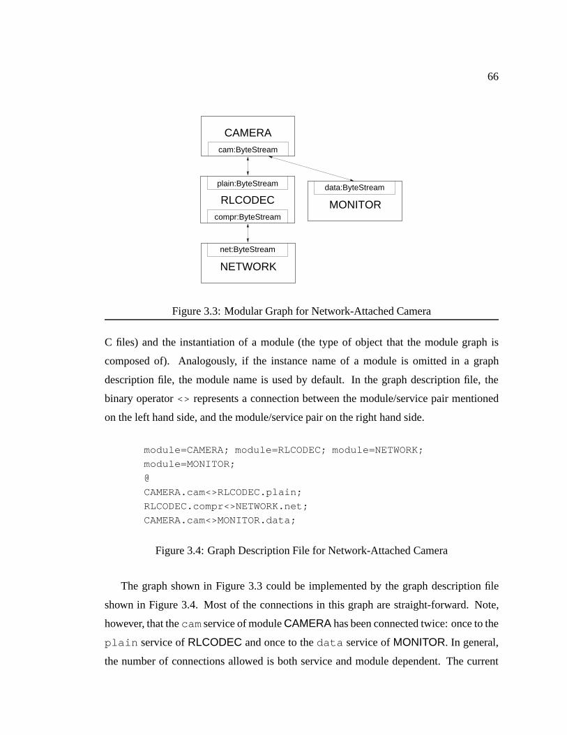
66
plain:ByteStream
compr:ByteStream
RLCODEC
net:ByteStream
NETWORK
cam:ByteStream
CAMERA
MONITOR
data:ByteStream
Figure 3.3: Modular Graph for Network-Attached Camera
C files) and the instantiation of a module (the type of object that the module graph is
composed of). Analogously, if the instance name of a module is omitted in a graph
description file, the module name is used by default. In the graph description file, the
binary operator<> represents a connection between the module/service pair mentioned
on the left hand side, and the module/service pair on the right hand side.
module=CAMERA; module=RLCODEC; module=NETWORK;
module=MONITOR;
@
CAMERA.cam<>RLCODEC.plain;
RLCODEC.compr<>NETWORK.net;
CAMERA.cam<>MONITOR.data;
Figure 3.4: Graph Description File for Network-Attached Camera
The graph shown in Figure 3.3 could be implemented by the graph description file
shown in Figure 3.4. Most of the connections in this graph are straight-forward. Note,
however, that thecamservice of moduleCAMERA has been connected twice: once to the
plain service ofRLCODEC and once to thedata service ofMONITOR. In general,
the number of connections allowed is both service and module dependent. The current
67
implementation of Scout does not provide the means to express such constraints in the
module’s spec file, but modules can ensure at runtime that the correct number of con-
nections have been made. This is the most flexible solution since the logic verifying the
connection count can take into account all of the information available at runtime; e.g.,
the number of expected connections may very well depend on the number of connections
made to another service of the same module. On the other hand, the experience gained so
far suggests that most services expect either at most one, exactly one, at least one, or an
arbitrary number of connections. Thus, supporting these constraints in the spec file would
seem like a good idea since that would help to catch most configuration errors at system
build time instead of at runtime. Moreover, this solution would not sacrifice flexibility:
in the case where none of the four proposed constraints is perfectly appropriate, the ser-
vice could specifyarbitrary number of connectionsas the constraint in the spec file and
perform the actual verification at runtime, as is presently done.
The semantics of multiply connecting the same service is also module dependent. In
the case of theCAMERA module, it presumably would mean that video data is sent to
both connections and that commands are accepted from either one. Multiple connections
are commonly used by modules that do some form of multiplexing and demultiplexing
among multiple data streams. Such modules essentiallyroutedata through the module.
Finally, as Figure 3.3 shows, a module graph often represents a layered system. That
is, higher-level modules provide services that are implemented in terms of other, lower-
level services. For reasons of flexibility, Scout does not, however, enforce strict layering.
Cyclic module graphs are admissible as long as there is a partial (non-cyclic) order in
which the modules can be initialized; more on this later.
3.2.3.1 Compatibility
A pair of services can be connected in the module graph only if they are compatible.
For the purpose of compatibility testing, a service consists of a pair of interface names:
the first element specifies the name of the interface that the serviceprovidesand the
second element specifies the name of the interface that the serviceexpects. Interfaces
are explained in detail in Section 3.3, but for the purpose of this discussion, it is sufficient
68
to think of an interface as a collection of (typed) routines that can be called by the user of
the interface.
A pair of services is considered compatible if the interfaceprovidedby one service is
compatible with the interfaceexpectedby the other service and vice versa. Suppose the
ByteStream service had been declared like this:
service ByteStream = <ByteStreamIface, ByteStreamIface>
This would mean that a service of typeByteStream provides an interface of type
ByteStreamIface and also expects an interface of the same type. This implies that a
ByteStream service can be connected to any otherByteStream service. Asymmet-
ric services are of course possible. The most common asymmetric case is where a service
provides an interface but does not expect any interface (or vice versa). This is used for
connections in which communication can be initiated in one direction only.
The current Scout implementation does not check for compatibility in a module graph.
Supporting this would again catch more configuration errors early in the lifetime of a
system, namely during build time.
3.2.3.2 Runtime Representation and Module Initialization
During build time, the module graph exists in the form of theconfig.graph descrip-
tion. Scout also provides an explicit representation of the module graph at runtime. This
makes it possible to address connections in the graph by names that are computable at
runtime (the names are actually integer indices). For example, theCAMERA module
described earlier needs to send out the video data on all connections to itscam service.
With a runtime representation of the graph, this can be achieved with a simplefor -loop.
Each modulemexports a global function calledmCreate that creates and returns an
object representing the module. The prototype for these functions is shown below:
Module mCreate (String n, int c[]);
Formal argumentn specifies the instance name of the module andc is an array that spec-
ifies how many times each service has been connected to other services. The module
69
creation function can verify the connection counts and, if correct, return the newly cre-
ated module, or if incorrect, returnNULL. The module creation functions are called by
the Scout runtime system at boot time. The order in which the modules are created is
unspecified.
The value returned by the module creation function is a pointer to a C structure of the
following type:
typedef struct Module f
String name;
String module name;
long (*init)(Module m);
CreateStageFunc createStage;
DemuxFunc demux;
struct ModuleLink f
Module module;
int service;
g links[][];
g * Module ;
The membersnameandmodule namehold the instance and module name of the mod-
ule, respectively. Function pointerinit is used to initialize the module. It is called once
the entire module graph has been built, that is, after all modules have been created and
connected according to the module graph description. ThecreateStage anddemux
members are function pointers that are used in conjunction with path creation and de-
multiplexing, respectively. These will be described later. The last member,links , is a
two-dimensional array of connections to other services. The first dimension in the array is
indexed by the service name and the second dimension is indexed by the instance number.
For example, for the graph in Figure 3.3,links[cam][0].module would point to the
object representing moduleRLCODEC andlinks[cam][0].service would be the
index that corresponds to theplain service. Similarly,links[cam][1].module
would point to the object representing moduleMONITOR and expressionlinks[ca-
m][1].service would evaluate to the index that corresponds to thedata service of
that module. The mapping from service names to integers is performed automatically by
the Scout infrastructure. It ensures that the service indices of a module withn services

70
will be unique and in the range from 0: : :n�1. Other than that, the mapping is arbitrary.
The analogous applies to the numbering of service connections.
As alluded to in the previous paragraph, the module initialization functions are called
once the runtime version of the module graph has been created. To a first approximation,
the order in which these functions are called is arbitrary. However, it is not uncommon
that initialization of a module requires the invocation of services provided by other mod-
ules. In support of this, the initialization order can be constrained using the less-than
marker described in 3.2.2. When a module is initialized, it is guaranteed that all modules
connected through services that are marked in this way have already been initialized. In
other words, the less-than marker imposes a partial order on module initialization. A valid
module graph may not contain any cyclic dependencies in the module initialization order
constraints.
3.2.4 Discussion
An interesting question is whether the choice of C as the implementation language com-
plicates the problem of realizing a modular system. If that were the case, then clearly a
more appropriate language would be desirable. However, there is little reason to believe
this to be true. For example, consider object-oriented languages. The main feature of
Scout’s module infrastructure is that it moves the point at which external interfaces are
bound from the time a module is implemented to the time a system is configured (cf., Fig-
ure 3.1). With an object-oriented language, the same can be achieved by realizing each
type of service as a separate class. Assuming modules are represented by their own class,
then a module could be instantiated by passing one service object for each connection in
the module graph. But in effect, this is just a slightly different implementation from the
modular system described earlier. In other words, object-oriented languages do not, by
themselves, provide a form of modularity that would be sufficient for Scout.
Just as important, a key challenge to building modular systems is to find and define an
appropriate set of interfaces. There are two conflicting goals in selecting interfaces. On
the one hand, an interface should be well-suited to the needs of a module. Otherwise, us-
ing the interface might be cumbersome and cause additional overhead for the module. On
71
the other hand, if this were followed to the extreme, then every module might end up us-
ing its own interface, meaning that they could not connected in to a useful module graph.
Note that this issue, too, is completely independent of the implementation language.
So, in summary, there seem to be few and only minor disadvantages to using a rela-
tively low-level language such as C. A major advantage of C, as far as systems program-
ming, is concerned is the transparency it affords: since it operates at such a low level, it
is generally easy to guess what kind of machine code a given piece of source code trans-
lates into. This reduces the likelihood of small changes in the source code inadvertently
leading to large performance differences. In this sense, using a language such as C im-
proves predictability at the programming level. The biggest disadvantage of using C is
likely to be found not in convenience-of-use issues, but in suitability for optimization. For
example, high level functional languages such as SML are more amenable to aggressive
optimization than C [8]. But the high level of abstraction that enables these aggressive
optimizations is also the reason that makes such languages difficult to compile into code
as efficient as C. As long as there is a performance differential on the order of a factor of
two or more, C appears to be a more practical choice.
Another modularity issue worth discussing is that the Scout module graph is presently
configured at build time and, hence, it is not possible to extend the graph at runtime. How-
ever, it is straight-forward to add a dynamic module-loading facility to Scout. The biggest
issue in doing so is the security issue, not the actual dynamic loading. An alternative to
extending the module graph at runtime would be to configure a virtual machine module
into the graph that would allow interpreted code to be downloaded and executed inside
Scout [39, 25].
3.3 Paths
This section describes how paths are realized in Scout. Scout paths closely follow the
model presented in Chapter 2. Since paths make frequent use of lists of name/value
pairs, this section begins with a description ofattributes—the Scout representation of
name/value pairs.
72
Each path is represented by several nested C objects. Since they recursively depend
on each other, they cannot be described in a linear fashion without forward references.
Thus, the approach taken here is to first present an overview of the objects involved,
then to discuss each of them individually in more detail. The descriptions of the objects is
followed by an introduction to path dynamics, which involves issues such as how paths are
created, used, and destroyed. The section concludes with a brief evaluation and discussion
of paths as implemented in Scout.
3.3.1 Attributes
In Scout, an attribute is a name/value pair. The corresponding C type is calledAttr .
The name of an attribute is a (unique) integer index that is usually written in the form
of a manifest constant. In contrast, the value can be of arbitrary type. The name of the
attribute implies the type of the value. In this sense, an attribute can be thought of as a
tagged union variable. Since the association between attribute name and the attribute’s
value type is by convention, it is not explicitly represented in the implementation. For
example, the attribute with nameMAX SIZE might (by convention) have a value of type
integer. Similarly, the attribute with namePEER ADDR might have a value that is a
pointer to a network address.
Sets of attributes are implemented in Scout by an abstract type calledAttrs . A
variable of this type can hold an arbitrary number of attributes. The operations supported
on attribute sets include insertion, and removal of attributes, enumeration of the attributes
present in the set, and membership test.
Why are attributes so important in Scout? They basically serve two different, but
equally fundamental roles. During path creation, attributes convey path invariants. In this
case, they are primarily a substitute for the variable length argument list support that is
missing in the C language (varargs are not defined by thelanguage, but by theruntime
system). But it is more than that. Attribute lists turn argument lists into first class objects,
that is, they make it possible to enumerate all elements in an argument list under program
control, and to dynamically add and remove elements in it.
The second role of attributes is in serving as information repositories that allow mu-
73
tually anonymous parties to communicate through a third, common party. Consider a
path that requires realtime scheduling. For such a path, there typically exists a deadline
by which a task has to be completed. The entity that can compute the deadline may be
somewhere in the middle of the path, but a device driver that enqueues newly arrived data
for the path may need to know what the current deadline is, so it can schedule the path
in an appropriate manner. This problem can be solved easily by using an attribute stored
in the path. All that is required is that the users of attributes agree that, for example,
attributeDEADLINE specifies a task deadline in units of micro-seconds. This attribute
attached to the path allows communicating the deadline from the middle of the path to
the device driver at the edge of the path. Note that this communication is anonymous: the
producer of the deadline does not know who makes use of the attribute and conversely,
the consumer does not know who produced the attribute. Also, the path object holding
the attributes does not have to understand the meaning of the attributes stored in it.
3.3.2 Visual Overview of a Scout Path
Figure 3.5 presents an enlarged view of the path and module graph originally presented in
Figure 2.4. The path is shown as the big rectangular box in the right half of the figure. For
space reasons, the middle of the path has been cut out of the figure. Internally, the path
contains four queues, shown near the top and bottom of the box representing the path.
It also contains several smaller boxes calledstages. As indicated, there is one stage per
module that the path traverses. Inside stages there are various labelled arrows. The exact
meaning of these arrows will be described in Section 3.3.4. Aside from the queues and
the stages, the path contains other minor objects which have been omitted in the figure
for the sake of clarity.
The stages inside the path are created by the modules along the path; e.g., the fig-
ure suggests that the bottom-most stage was created byFDDI. Stages provide a place to
store information that is path-specific, but private to the modules. For example, the stage
created by moduleIP might contain a pre-formatted IP-header that is used when sending
data from the path to the network. Since no other module along the path needs to know
about IP headers, it is best to store it in the stage created by moduleIP.

74
next
stageback
next
backstage
next
backstage
next
stageback
FDDI
MPEG
MFLOW
UDP
IP
path
path
path
path
interfaces
backstage
next
stageback
next
DISPLAY stages
path
module
module
module
module
iface[1]iface[0]
iface[0]
iface[1]
iface[0]
iface[1]
iface[0]
iface[1]
WiMP
Figure 3.5: Path Structure
75
The figure also shows that stages contain semi-circular shapes, calledinterfaces. An
interface provides a controlled (type-checked) way to move data from one stage to the
next one. Interior stages typically have a pair of interfaces (one per direction) whereas
stages at the ends of the path typically contain just one interface.
The figure further shows that interfaces are chained together. The interfaces in the left
half of the path are used to move data from the top end of the path towards the bottom,
whereas the interfaces in the right half are used to move data from the bottom end towards
the top. As discussed in Chapter 2, it is sometimes necessary to turn around the direction
in which data flows. This is supported by the arrows in the interfaces that are labelled
back. That is, when data arrives at an interface, it is possible to continue moving it in the
same direction by passing it along the arrow labellednext, or it can be turned around and
passed along the arrow labelledback.
3.3.3 Path Object
The most important elements of the actual Scout path object are shown in the C structure
below. In addition to the members shown, the Scout path object contains state that assists
the creation, extension and destruction of paths. That state has been omitted since it is not
relevant to the discussions presented here.
typedef struct Path f
long pid;
Stage end[2];
PathQueue q[4];
struct Attrs attrs;
bool realtime;
u long prio;
g * Path ;
Every path has a unique integer associated that is called thepath id. This id is stored in
memberpid , and permits accounting resources on a per-path basis. The id is guaranteed
to be unique, but is otherwise arbitrary. In particular, ifn paths exist in the system, it is
not guaranteed that the path id is in the range 0::n�1.
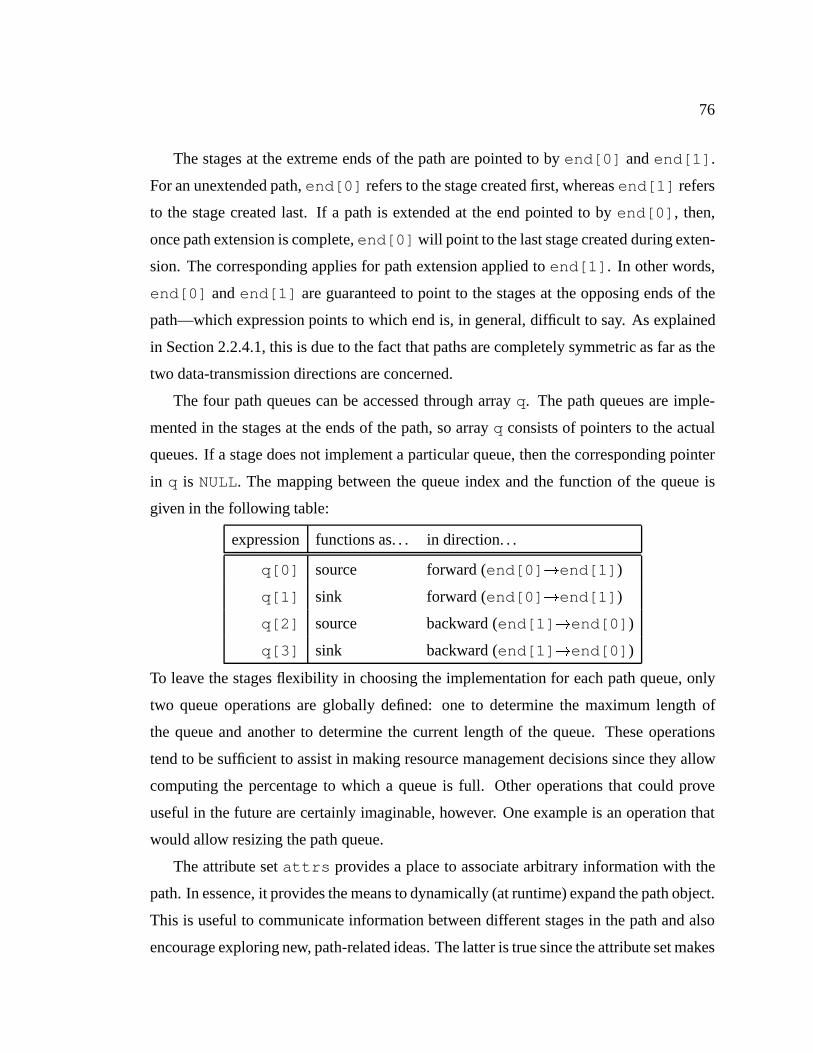
76
The stages at the extreme ends of the path are pointed to byend[0] andend[1] .
For an unextended path,end[0] refers to the stage created first, whereasend[1] refers
to the stage created last. If a path is extended at the end pointed to byend[0] , then,
once path extension is complete,end[0] will point to the last stage created during exten-
sion. The corresponding applies for path extension applied toend[1] . In other words,
end[0] andend[1] are guaranteed to point to the stages at the opposing ends of the
path—which expression points to which end is, in general, difficult to say. As explained
in Section 2.2.4.1, this is due to the fact that paths are completely symmetric as far as the
two data-transmission directions are concerned.
The four path queues can be accessed through arrayq. The path queues are imple-
mented in the stages at the ends of the path, so arrayq consists of pointers to the actual
queues. If a stage does not implement a particular queue, then the corresponding pointer
in q is NULL. The mapping between the queue index and the function of the queue is
given in the following table:
expression functions as. . . in direction. . .
q[0] source forward (end[0] !end[1] )
q[1] sink forward (end[0] !end[1] )
q[2] source backward (end[1] !end[0] )
q[3] sink backward (end[1] !end[0] )
To leave the stages flexibility in choosing the implementation for each path queue, only
two queue operations are globally defined: one to determine the maximum length of
the queue and another to determine the current length of the queue. These operations
tend to be sufficient to assist in making resource management decisions since they allow
computing the percentage to which a queue is full. Other operations that could prove
useful in the future are certainly imaginable, however. One example is an operation that
would allow resizing the path queue.
The attribute setattrs provides a place to associate arbitrary information with the
path. In essence, it provides the means to dynamically (at runtime) expand the path object.
This is useful to communicate information between different stages in the path and also
encourage exploring new, path-related ideas. The latter is true since the attribute set makes

77
it possible to associate new state with a path without requiring compile-time modifications
the path object type. Also, path attributes are useful for performance measurements. It is
often the case that the measurements are performed in one part of the path, but reported
in another, or that measurements need to be accumulated over a certain period of time.
Both cases can be accommodated easily using attributes to store performance statistics in
the path object.
The last two members listed in the structure arerealtime andprio . These rep-
resent the scheduling parameters of the path and will be described in more detail later in
Section 3.5.
3.3.4 Stage
Figure 3.5 shows that path-interior stages essentially represent fixed routing decisions:
data enters the stage, which is then processed by code specific to the module that created
the stage, and, eventually, leaves the stage through the other side. In a traditional system
without paths, the module-specific processing would also require a routing decision to
determine where to send the data next. In contrast, interior stages have these decisions
pre-made (builtin). However, the stages at the ends of the path are special. They do not
represent fixed routing decisions. Instead they simply serve as hooks into the modules
at which the path terminates. These are the modules that will need to make dynamic
routing decisions to find out where to send the data next. In the ideal case, a path termi-
nates at modules at the edge of the module graph, where data is simply passed on to the
appropriate device. For this case, all dynamic routing decisions can be avoided.
The C structure that implements the stage object in Scout is shown below:
typedef struct Stage f
Iface iface[2];
Path path;
Module module;
long (*establish)(Stage s, Attrs a);
void (*destroy)(Stage s);
Stage nextStage;
g * Stage ;
78
The elements of arrayiface are pointers to the interfaces in the stage. If such an in-
terface does not exist, the corresponding element isNULL. Expressioniface[0] refers
to the interface on the side of the stage through which the creation request for this path
arrived (see Section 3.3.6). For an unextended path, this is equivalent to the interface in
the forward direction of the path. Expressioniface[1] refers to the other interface
in the stage. For an unextended path, this is equivalent to the interface in the backward
direction of the path. For stages that were created as part of a path extension, this simple
and direct relationship between the elements in arrayiface and the path direction does
not hold, however.
The path to which the stage belongs is pointed to bypath . Similarly, the module
that created the stage can be accessed through membermodule . The function pointers
establish anddestroy are used during path creation and destruction and are ex-
plained in detail later in this section. The final member,nextStage , is part of a chain
that lists all of a path’s stages in the order in which they were created. Due to path exten-
sion, this chain does not necessarily correspond to a linear traversal of the path and hence
is typically used during path creation and destruction only.
3.3.5 Interface
As mentioned in the overview, interfaces are used to move data from one stage to the next
one. The simplest possible interface has the structure shown below:
typedef struct Iface f
Iface next;
Iface back;
Stage stage;
g * Iface ;
In words, the most primitive interface simply consists of anext pointer that refers to
the next interface in the current direction of the path, aback pointer that refers to the
next interface in the opposite direction, and astage pointer that refers to the stage that
the interface belongs to. This is simple, but does not provide any way to deliver data to
the interface. Thus, all useful interfaces are expanded versions of this primitive interface.
That is, Scout uses single inheritance for interfaces [38]. For example, the interface that

79
is commonly used to pass amessage(a sequence of data bytes) to an interface is called
AioIface (asynchronous I/O interface). This interface looks the same as the basic
Iface , except that it additionally declares a function pointer that can be used to deliver
a message:
typedef struct AioIface f
struct Iface i;
long (*deliver)(Iface i, Msg m);
g * AioIface ;
To deliver messagem to the asynchronous I/O interfacei , one would simply invoke
i->deliver (i, m) .
Since interfaces provide for single inheritance, the service compatibility rules pre-
sented in Section 3.2.3.1 can be slightly relaxed: if a service requires an interface of type
T, then any interface type that is equal to or a subtype ofT can be used to satisfy this
requirement. For example, if interface typeIface were required, then an interface of
typeAioIface could be used instead. This is sensible since any asynchronous I/O in-
terface is also a plain interface. A more interesting example involves TCP since, to a
first approximation, TCP provides a bytestream, it clearly would be desirable if it were
possible to connect TCP to any other module that requires a bytestream. However, a so-
phisticated user of TCP might want to adjust its flow-control window sizes, so it would
be useful if TCP provided functions to do so. With single inheritance, TCP can use a sub-
type of AioIface that provides the additional functions needed to adjust the window
sizes. Suppose that subtype was calledWindowedAioIface . With this arrangement,
a sophisticated user that depends on being able to control window sizes could specify
a service that requires an interface of typeWindowedAioIface , whereas naive users
could continue to connect to TCP as if it were a regular asynchronous I/O interface.
Technically, Scout can support an arbitrary number of interface types. However, the
more interface types there are, the less likely that any given pair of services can be con-
nected. Thus, the intent is to keep this number as small as possible. At present, there
are about eight different interface types that are relatively stable and in frequent use. In
addition to those, there are another eight interface types related to the disk subsystem.
80
Since that subsystem is still being evolved, its interfaces are not as well factored and sta-
ble as the others. The simplest useful interface, asynchronous I/O, is employed by many
data filters and almost all modules related to networking. The most complicated interface
so far is a window management system interface that defines more than thirty distinct
operations.
The decision as to whether a new module should be coerced into using existing in-
terface types or whether a new interface type should be defined instead is sometimes not
easy. It should be guided by the semantics of the operation involved and by performance
considerations. Semantics must be taken into consideration to ensure that compatible
services really result in meaningful behavior when connected. If performance were not
taken into account, there would be no reason to support multiple interfaces, since every-
thing could be built based on a universal data-delivery function such as thedeliver
function in the asynchronous I/O interface.
3.3.6 Creation
Now that all parts of the Scout path have been described, it is possible to explain the
details of path creation. Scout provides a singlepathCreate function for this purpose.
Its C prototype is given by:
Path pathCreate (Module m, Attrs a);
As the prototype suggests, a path is created by invoking the function on a modulemwith
an attribute seta. The attribute set describes the kind of path that is desired. That is, the
invariants discussed in Chapter 2 are passed in this set.
The call topathCreate eventually results in an invocation of thecreateStage
function in modulem (see Section 3.2.3.2). ThecreateStage function has the follow-
ing type:
Stage (*CreateStageFunc)(Module m, int s, Attrs a,
ModuleLink* n);
In the prototype, argumentmis the module on whichpathCreate was invoked ands is
the index of the service through which the path being created entered the module. Since
mis the first module in the path, there is no such service, so a value of -1 is passed (which

81
is not a valid service index). Argumenta is the set of attributes that was passed to the
pathCreate function. In response to this invocation, thecreateStage function is
expected to allocate and initialize a stage and the interfaces contained therein. As part of
this processing, the function may also update the attribute set as new information about the
path may become available in the module or existing information may become obsolete.
After creating the new stage, the module attempts to make a routing decision based on
the attributes (invariants) that were passed to it. If the module can decide where the path
has to go next, it sets*n to point to the module and service index of that next point. If
no routing decision can be made based on the attributes, then path creation stops at this
module and*n is set toNULL.
If the call to createStage returned a non-NULL value in*n , then path creation
continues at the point given by*n . This is done by invokingcreateStage on the
module indicated by*n and with arguments set to the service index specified in*n . The
attribute seta is the possibly updated set returned by the previouscreateStage invo-
cation. The reason the service indexs is passed to the stage creation routine is because
stages usually need to be created differently depending on the service through which the
path entered the module. In a sense, the service index is a very short-lived path invariant,
but since it changes so frequently (with every stage creation call), it is more efficient and
more convenient to pass it as a separate function argument. Given the service index and
the current attribute set, a new stage is created and a routing decision made and stored in
*n , if possible. This process repeats until the path reaches its full length which happens
either when it reaches a leaf module or when the attributes are too weak for a module to
make a static routing decision.
Once the path has reached its full length, a sequence of stages exists. At this point,
thepathCreate function creates the actual path object, inserts the stages into it, and
establishes the various chains through the path structure. In a third step, theestablish
callbacks in the stage objects are invoked in the order in which the stages were created.
The establish callbacks are necessary since some stages cannot be fully initialized until
the entire path structure exists. The first argument passed to theestablish callback
is a self-reference to the stage being established and the second argument is an attribute

82
set. This attribute set is initialized to the empty set before invoking the first callback. The
establish callbacks may use and modify this attribute set as necessary and then pass it on
to the next establish callback. The purpose of this attribute set is to allow passing auxil-
iary information between neighboring stages. This can be done safely since neighboring
stages are known to be compatible in the sense defined in Section 3.2.3.1. An example
for such auxiliary information is attributePREVIOUSDEMUXNODE, which will be de-
scribed in Section 3.4.3. Note that the attribute set used in the establish callbacks has
nothing in common with path invariants or the attribute set passed topathCreate .
3.3.7 Extension
The path extension function operates analogously to the path creation function. The only
difference is that path extension is invoked at the end of an existing path, rather than on a
module. The prototype for this function is shown below:
long pathExtend (Stage s, Attrs a);
The first argument, stages , points to the end of the path that should be extended. If path
p is being extended, this must be eitherp->end[0] or p->end[1] . If s points to any
other stage, path extension will fail. The second argument, attribute seta, is the set of
invariants that are true for the path extension operation.
If path extension fails for any reason (e.g., because the system runs out of memory),
then the path being extended is destroyed as well. This fate sharing is reasonable since an
extended path is still just one path; it does not consist of two independent sub-paths. It is
therefore only logical that if path extension fails, then the entire path creation should be
considered to have failed.
For path extension to make sense, the attribute set must be consistent with the one
specified in thepathCreate call and those specified during previous calls topath-
Extend (if any). Scout does not have a formal model for path invariants. Thus, it is not
possible to give a formal procedure to test whether a pair of attribute sets is consistent.
Informally, it is easier to discuss cases that make attribute set pairs inconsistent. For
example, if the first set contains the invariant that the path needs to be scheduled using
a realtime scheduler and the second set contains an invariant that request a best-effort

83
scheduler, then the attribute sets are inconsistent. Such direct contradictions are relatively
easy to detect. More subtle are inconsistencies that arise fromnot specifying invariants;
e.g., the first attribute set may contain an invariant that says no single data-item (message)
is going to be larger than 100 bytes, while the second attribute set may not have any
invariants related to the size of messages, so even though there is no direct contradiction
in the invariants, the attribute sets may be inconsistent.
The reason we introduced the issue of attribute set consistency here is that the problem
is most apparent with path extension. However, it is not limited to this operator. Since the
create-stage functions may update the attribute set, consistency problems may arise within
a single path creation operation. Note that prohibiting stage creation from updating the
invariant set is not a solution since modules do process and modify data, and as a result,
invariants may have to be updated to reflect those changes.
3.3.8 Optimization
The current incarnation of Scout does not employ an explicitpathOptimize function
to apply the path transformations described in Chapter 2. Instead, path transformations
are applied in an ad hoc fashion. This certainly will not be sufficient in the long run, but
does have the advantage of providing maximum flexibility in experimenting with path
transformations. A sample path transformation designed to improve processing speed
inside will be discussed in detail in Chapter 4.
While no explicit path optimization routine exists, it is important to point out that it
is straight-forward to replace the code of a path with a more optimized version. This is
because interfaces contain function pointers, not actual code. Hence, to replace the code
used by a path, all that needs to be done is change the function pointers in the interfaces
to make them point to the optimized versions.
3.3.9 Destruction
The final path-related operation allows one to destroy a path when it is no longer needed.
The C prototype for this operation is shown below:
void pathDelete (Path p);
84
Invocation of this function will eventually cause pathp to be destroyed. However, before
this happens, thedestroy callbacks in the path’s stages are called in the order in which
the stages were created. The only argument passed to this callback is the stage (and,
implicitly, the path) that is being destroyed. The destroy callback of a stage needs to
ensure that all resources held by the stage are relinquished. Once all callbacks have been
executed, the resources held by the path are relinquished and the path ceases to exist.
3.3.10 Evaluation and Discussion
As implemented in Scout, paths are light-weight. For example, a path to transmit and
receive UDP network packets consists of six stages. Creating such a path on a first-
generation, 21064A 300MHz Alpha takes on the order of 200µs (not including the appli-
cation of any potential path optimization transformations). The path object itself is about
300 bytes long and each stage is on the order of 150 bytes in size, including all the inter-
faces. In total, each UDP path takes about 1200 bytes. Since interfaces consist of pointers
to functions, creating a path does not cause any code duplication. Code duplication can
occur only as a result of path transformations.
The current Scout architecture does not support multiple protection domains. How-
ever, extending Scout paths to multiple protection domains should be straight-forward.
Indeed, paths raise the interesting opportunity to use protection not just betweenlayers
(horizontal partitioning) but also betweenpaths(vertical partitioning). With horizontal
partitioning, layers are protected from each other, whereas with vertical partitioning the
paths are protected from each other. Depending on the needs of a system (e.g., debugging
of a new layer versus ensuring the integrity of the data sent through a path), one or the
other or even a combination of the two may be appropriate.
For horizontal partitioning, note that all communication between stages is through
a pair of interfaces. Splitting a path at such a boundary into two protection domains
would therefore be rather natural and easy. Another concern is that the actual path object
needs to be accessible from all protection domains that a path crosses. Different solutions
are conceivable. One would involve caching the path object in the different domains.
Another would involve keeping the path object in a protection domain that is accessible
85
by all other domains. A third would involve accessing the path object through a system
call-like interface. Most likely, an actual implementation would use a combination of the
three proposed solutions, but the key point is that there do not seem to be any unusual
difficulties in defining paths that cross multiple protection domains.
Vertical partitioning does not appear to be problematic either. The entire path would
be contained in its own protection domain and the domain would have to be crossed only
when moving from a module into a path or vice versa. Ideally, paths directly connect
modules representing device pairs, so the number of domain crossings for moving data
from a source device to sink device would be two, just as is the case with a traditional,
monolithic kernel based system [95].
3.4 Demultiplexing
So far, we have not discussed the issue of how the appropriate path is found for a given
message. In many cases, this is trivial. For example, a path is often used like a file
descriptor, a window handle, or a socket descriptor. In these cases, paths are created
specifically for communicating a certain kind of data and the appropriate path is known
from the context in which it is being used. In other cases, however, there is no such
context and the appropriate path is implicitly determined by the data itself. The most
notable area where this is the case is for the networking subsystem. Networking protocols
typically require hierarchical demultiplexing for arriving network packets. For example,
when a network packet arrives at an Ethernet adapter [65], the Ethernet type field needs
to be looked up to determine whether the packet happens to be, e.g., an IP packet or
an ARP packet. If it is an IP packet, it is necessary to look up the protocol field to
determine whether it is a UDP or TCP packet, and so on. This hierarchical demultiplexing
is suboptimal since as more knowledge becomes available with each demultiplexing step,
another path might become more suitable to process that packet.
3.4.1 Scout Packet Classifier
To alleviate the hierarchical demultiplexing problem, Scout uses a packet classifier that
factors all demultiplexing operations to the earliest possible point. This lets Scout pick a

86
path and start processing a packet only after as many demultiplexing decisions as possible
have been made. Of course, a solution that would be better still (as far as Scout is con-
cerned) would be to modify the header of the lowest layer protocol to include a field that
can store the path id [56]. That way, demultiplexing could be reduced to a simple table
lookup. However, since Scout needs to be able to interoperate with existing networking
infrastructure, this is not always an option.
The factoring of demultiplexing decisions is best explained with an example. Suppose
a UDP packet were received by an Ethernet adapter. The processing that would occur with
hierarchical demultiplexing is shown on the left, with a classifier on the right:
Without Classifier: With Classifier:
Ethernet processing Ethernet demux) it’s an IP packet
Ethernet demux) it’s an IP packet IP demux) it’s a UDP packet
IP processing Ethernet processing
IP demux) it’s a UDP packet IP processing
UDP processing UDP processing...
...
As the left half of the table shows, without a classifier, processing would have to occur in
a layer by layer fashion since each layer is decoupled by a demultiplexing step (shown in
bold). In contrast, the right half of the table shows that with a classifier, all demultiplexing
operations are performed first, which makes it possible to execute all protocol processing
steps inside a single, long path. Note that the total amount of work is same: there are two
demultiplexing steps and three processing steps in both cases. What the table does not
show is that the demultiplexing steps are usually much shorter than the processing steps,
so the actual time spent in the classifier is typically much smaller than the time spent in
the processing steps.
3.4.2 The Role of Classifiers
The way packet classifiers are used in Scout is unique and therefore worth discussing
in some more detail. In particular, their role with respect to dynamic routing decisions
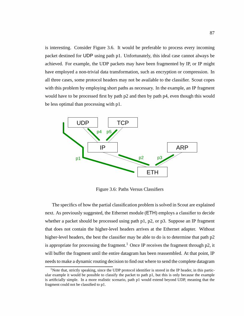
87
is interesting. Consider Figure 3.6. It would be preferable to process every incoming
packet destined forUDP using path p1. Unfortunately, this ideal case cannot always be
achieved. For example, the UDP packets may have been fragmented by IP, or IP might
have employed a non-trivial data transformation, such as encryption or compression. In
all three cases, some protocol headers may not be available to the classifier. Scout copes
with this problem by employing short paths as necessary. In the example, an IP fragment
would have to be processed first by path p2 and then by path p4, even though this would
be less optimal than processing with p1.
p3p2p1
p5p4
ETH
ARPIP
TCPUDP
Figure 3.6: Paths Versus Classifiers
The specifics of how the partial classification problem is solved in Scout are explained
next. As previously suggested, the Ethernet module (ETH) employs a classifier to decide
whether a packet should be processed using path p1, p2, or p3. Suppose an IP fragment
that does not contain the higher-level headers arrives at the Ethernet adapter. Without
higher-level headers, the best the classifier may be able to do is to determine that path p2
is appropriate for processing the fragment.1 Once IP receives the fragment through p2, it
will buffer the fragment until the entire datagram has been reassembled. At that point, IP
needs to make a dynamic routing decision to find out where to send the complete datagram
1Note that, strictly speaking, since the UDP protocol identifier is stored in the IP header, in this partic-ular example it would be possible to classify the packet to path p1, but this is only because the exampleis artificially simple. In a more realistic scenario, path p1 would extend beyond UDP, meaning that thefragment could not be classified to p1.
88
next. IP can do this by running itsownclassifier on the complete datagram, which, with
a UDP packet, will tell IP that p4 should be used.
This example shows that, in Scout, a classifier is not something specific to network
drivers, but instead is a mechanism that can be employed by any module that needs to
make a dynamic routing decision based on the contents of the data being communicated.
Typically, each network device driver uses a classifier which is invoked when a packet re-
ceive interrupt is processed, but other modules may use their own classifiers if necessary.
3.4.3 Realizing the Scout Classifier
Since Scout is a modular system, we would like to be able to express classification in a
modular fashion as well. That way, the complete classifier can be built automatically from
partial classification algorithms that are specified by the module that appear along a path.
Note that a modular specification of the classifier does not necessarily imply a modular
implementation, though this is true for the current Scout implementation.
As discussed earlier, classifiers are used in Scout by any module that may need to
make a dynamic routing decision based on the contents of a message. The task of a
classifier can therefore be described as: given a modulem and a message, determine a
path that is appropriate for processing the given message. Since it is modulem that is
making the routing decision, the path must start at that module.
The classification task can be implemented in an iterative fashion using partial clas-
sifiers of the following form: given a set of paths and a message, determine the subset
of paths that qualify for the processing of the given message, the module that needs to
make the next (refining) classification (if any), and the message for that next module. The
message for the next module is normally the same as the original message, except that
the protocol header at the front of the message will have been stripped off. This scheme
works as long as the classification problem is locally hierarchical. The ramifications of
this constraint will be explained in detail in Section 3.4.3.1. For now, we assume that
the Scout classification problem satisfies this constraint. Using such partial classifiers,
the problem can be solved with the pseudo-code shown in Figure 3.7. Lines 2–5 of the
pseudo-code determine the set of paths that either begin or end at modulem. This path set
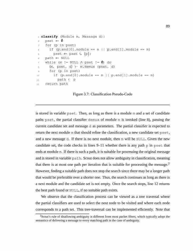
89
1 classify (Module m, Message d):2 pset /03 for (p in pset)4 if (p.end[0].module == m || p.end[1].module == m)5 pset pset [ fpg;6 path NULL7 while (m != NULL ^ pset != /0) do8 hm, pset, d i m.demux (pset, d)9 for (p in pset)
10 if (p.end[0].module == m || p.end[1].module == m)11 path p12 return path
Figure 3.7: Classification Pseudo-Code
is stored in variablepset . Then, as long as there is a modulemand a set of candidate
pathspset , the partial classifierdemux of modulem is invoked (line 8), passing the
current candidate set and messaged as parameters. The partial classifier is expected to
return the next modulemthat should refine the classification, a new candidate setpset ,
and a new messaged. If there is no next module, thenmwill be NULL. Given the new
candidate set, the code checks in lines 9–11 whether there is any pathp in pset that
ends at modulem. If there is such a path, it is suitable for processing the original message
and is stored in variablepath . Scout does not allow ambiguity in classification, meaning
that there is at most one path per iteration that is suitable for processing the message.2
However, finding a suitable path does not stop the search since there may be a longer path
that would be preferable over a shorter one. Thus, the search continues as long as there is
a next module and the candidate set is not empty. Once the search stops, line 12 returns
the best path found orNULL, if no suitable path exists.
We observe that the classification process can be viewed as a tree traversal where
the partial classifiers are used to select the next node to be visited and where each node
corresponds to a path set. This tree-traversal can be implemented efficiently. Note that
2Scout’s rule of disallowing ambiguity is different from most packet filters, which typically adopt thesemantics of delivering a message to every matching path in the case of ambiguity.
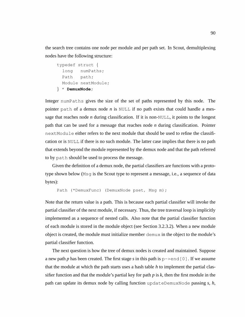
90
the search tree contains one node per module and per path set. In Scout, demultiplexing
nodes have the following structure:
typedef struct f
long numPaths;
Path path;
Module nextModule;
g * DemuxNode;
IntegernumPaths gives the size of the set of paths represented by this node. The
pointerpath of a demux noden is NULL if no path exists that could handle a mes-
sage that reaches noden during classification. If it is non-NULL, it points to the longest
path that can be used for a message that reaches noden during classification. Pointer
nextModule either refers to the next module that should be used to refine the classifi-
cation or isNULL if there is no such module. The latter case implies that there is no path
that extends beyond the module represented by the demux node and that the path referred
to bypath should be used to process the message.
Given the definition of a demux node, the partial classifiers are functions with a proto-
type shown below (Msg is the Scout type to represent a message, i.e., a sequence of data
bytes):
Path (*DemuxFunc) (DemuxNode pset, Msg m);
Note that the return value is a path. This is because each partial classifier will invoke the
partial classifier of the next module, if necessary. Thus, the tree traversal loop is implicitly
implemented as a sequence of nested calls. Also note that the partial classifier function
of each module is stored in the module object (see Section 3.2.3.2). When a new module
object is created, the module must initialize memberdemux in the object to the module’s
partial classifier function.
The next question is how the tree of demux nodes is created and maintained. Suppose
a new pathp has been created. The first stages in this path isp->end[0] . If we assume
that the module at which the path starts uses a hash tableh to implement the partial clas-
sifier function and that the module’s partial key for pathp is k, then the first module in the
path can update its demux node by calling functionupdateDemuxNode passings, h,

91
k andNULLas arguments in this order. TheupdateDemuxNode function is illustrated
with the pseudo-code shown in Figure 3.8. In line 3, the function concatenates the bits
1 void2 updateDemuxNode (Stage s, HashTable h, Key k, DemuxNode pn) f
3 dk = concat (pn, k);4 n = hashLookup (h, dk);5 if (!n) f
6 n = new (DemuxNode);7 n->numPaths = 0;8 n->path = NULL;9 n->nextModule = next module in path ;
10 hashEnter (h, dk, n);11 g
12 if (s == s->path->end[1])13 n->path = s->path;14 else if (pn)15 n->path = pn->path;16 ++n->numPaths;17 g
Figure 3.8: Update of Demux Tree
of the previous demux node with those for the partial keyk . Since this is the first stage
in the path, there is no previous demux node (pn is NULL), sodk equalsk . In line 4,
the demux node is looked up using the demux key. If no demux node exists for that key
yet, lines 6–10 create a new node and enter it in the hash table. In lines 12–15, thepath
member of the node is updated if necessary. Specifically, if stages is the last stage of the
path, then pathp can be used for any message that gets classified at least to noden. If
the end of the path has not been reached yet,n->path is simply set to the path of the
previous node, or left unmodified if there is no previous node. In line 16, the number of
paths in the path set represented byn is incremented.
A demux node is normally updated during the establish callback of a stage. Note that
the same routine can be used to update the demux nodes for all stages in a newly created
path. The only difference compared to the first stage is thatpn , the previous node pointer
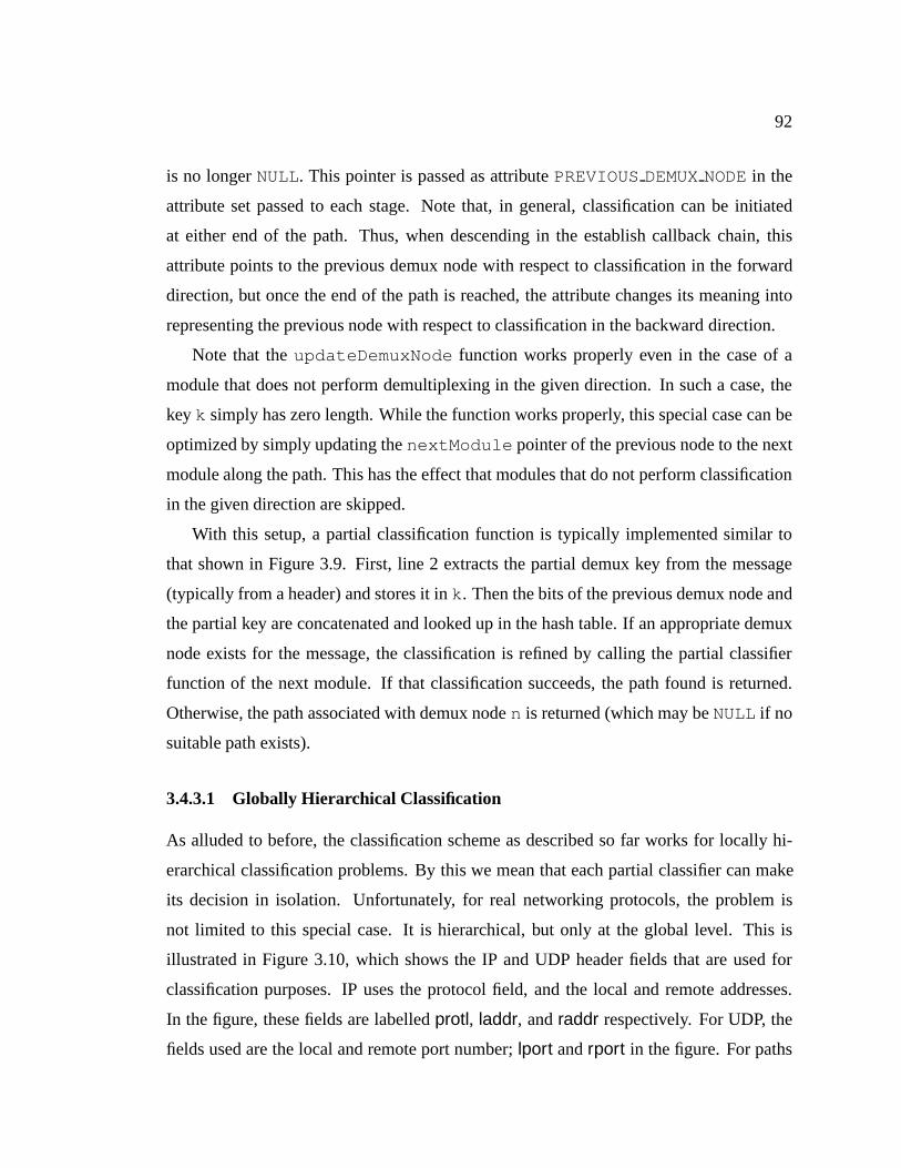
92
is no longerNULL. This pointer is passed as attributePREVIOUSDEMUXNODEin the
attribute set passed to each stage. Note that, in general, classification can be initiated
at either end of the path. Thus, when descending in the establish callback chain, this
attribute points to the previous demux node with respect to classification in the forward
direction, but once the end of the path is reached, the attribute changes its meaning into
representing the previous node with respect to classification in the backward direction.
Note that theupdateDemuxNode function works properly even in the case of a
module that does not perform demultiplexing in the given direction. In such a case, the
keyk simply has zero length. While the function works properly, this special case can be
optimized by simply updating thenextModule pointer of the previous node to the next
module along the path. This has the effect that modules that do not perform classification
in the given direction are skipped.
With this setup, a partial classification function is typically implemented similar to
that shown in Figure 3.9. First, line 2 extracts the partial demux key from the message
(typically from a header) and stores it ink . Then the bits of the previous demux node and
the partial key are concatenated and looked up in the hash table. If an appropriate demux
node exists for the message, the classification is refined by calling the partial classifier
function of the next module. If that classification succeeds, the path found is returned.
Otherwise, the path associated with demux noden is returned (which may beNULL if no
suitable path exists).
3.4.3.1 Globally Hierarchical Classification
As alluded to before, the classification scheme as described so far works for locally hi-
erarchical classification problems. By this we mean that each partial classifier can make
its decision in isolation. Unfortunately, for real networking protocols, the problem is
not limited to this special case. It is hierarchical, but only at the global level. This is
illustrated in Figure 3.10, which shows the IP and UDP header fields that are used for
classification purposes. IP uses the protocol field, and the local and remote addresses.
In the figure, these fields are labelledprotl, laddr, andraddr respectively. For UDP, the
fields used are the local and remote port number;lport andrport in the figure. For paths

93
1 Path demux (DemuxNode pn, Msg m) f
2 extract key k from m;3 dk = concat (pn, k);4 n = hashLookup (h, dk);5 if (n) f
6 if (n->nextModule)7 path = n->nextModule->demux (n, msg);8 if (path)9 return path;
10 return n->path;11 g
12 return NULL;13 g
Figure 3.9: Typical Partial Classifier
laddr=192.12.69.168raddr=18.181.0.21
rport=3949protl=UDP
IP UDP
lport=21
Figure 3.10: Example Requiring Global Hierarchical Classification
that represent actively opened network connections (active paths), all five fields need to be
matched. On the other hand, for paths representing passively opened connections (passive
paths), only the protocol field and local port field need to be matched. This means that the
classification process is still hierarchical, but only at the global level. Suppose a system
has the mappings shown in Table 3.1 in place. If a packet with the fieldshprotl=UDP,
laddr=192.12.69.168, raddr=18.181.0.21, lport=21, rport=3950i were to arrive, then
IP could not make a proper decision as to whether the path subset it passes to UDP should
include both the active path and the passive path or only the former. If it were to pass
on the active path only, classification would erroneously fail, since there is no active path
matching the packet. On the other hand, if it were to pass on both paths, then classifica-
tion would be erroneously ambiguous for packets that belong to the active path. That is,

94
protl laddr raddr lport rport maps to:hUDP, any any 21, anyi ) path 1 (passive)hUDP, 192.12.69.168, 18.181.0.21, 21, 3949i ) path 2 (active)
Table 3.1: Example Mappings
whether IP should use the fields for an active path or the a passive path depends on the
classification decision of UDP. Since IP cannot know how UDP’s partial classifier works,
it may make the wrong choice no matter how careful it is.
To solve this problem in general, it is necessary to try to find a path with the most
specific keys first and, if that fails, backtrack and try the same with a less specific key.
For example, networking protocols such as IP that distinguish between active and passive
keys, could use logic similar to the one shown in Figure 3.11. In the figure, functions
1 path try active demux (pn, m);
2 if (!path)
3 path try passive demux (pn, m);
Figure 3.11: Generalized Partial Classifier
try active demux andtry passive demux correspond to classifiers as shown in
Figure 3.9 that use the active and passive keys, respectively. With this kind of backtrack-
ing in place, it is guaranteed that the correct combination of keys is eventually found and
therefore classification is guaranteed to find the correct path, if it exists.
Unfortunately, adding backtracking causes classification complexity to increase from
O(N) to O(2N), whereN is the number of partial demux functions that require backtrack-
ing. Even though this involves exponential complexity, it might be quite practical since
the number of demultiplexing layers is rarely bigger than four or five (not all of which may
require backtracking). Better still, for networking protocols backtracking can be limited
in a way that allows bringing back classification to linear time complexity. Observe that

95
for the vast majority of systems, it is acceptable to limit paths to use either all active or all
passive keys.3 In this limited scenario, classification can be achieved by first trying to find
an active path. If an active key lookup anywhere along the chain of partial classifiers fails,
then classification can be aborted and retried with passive keys only. Thus, in the worst
case, 2N classification decisions have to be made, whereN is the number of modules that
are traversed by a path. Note that this scheme does notforcelimited backtracking in every
module. If there are any modules that require richer backtracking (e.g., because there are
more than two possible choices), then they can still do so. In other words, this scheme
reduces classification overhead to linear time complexity for the common case yet is not
limited to locally hierarchical classification.
3.4.3.2 Classification in Non-Demultiplexing Modules
Most demultiplexing occurs in modules implementing networking protocols, but it cer-
tainly is desirable to be able to connect modules implementing networking protocols and
other modules without any bad consequences (as long as the module graph is sensible).
For example, a filter that converts MPEG-encoded video into a sequence of images should
work properly independent of whether its input is fed from a disk or the network. Simi-
larly, it should be possible to insert a filter (e.g., one that counts the number of bytes that
pass through it) between a pair of networking protocols (e.g., TCP and IP) and have the
system operate as expected.
This kind of support requires answering how demultiplexing needs to be interpreted
with respect to modules that do not perform any demultiplexing themselves. Fortunately,
this is straight-forward in Scout: a module simply needs to ensure that its partial classifier
applies the same data transformations as the actual processing. If the data is not trans-
formed at all (such as in the byte-counting filter mentioned previously), then the partial
classifier would not have to do anything either. On the other hand, if a module modifies
all data passing through it—e.g., by complementing it—then the partial classifier would
3This is indeed a common restriction. For example, while thex-kernel [49] does not explicitly enforcesuch a restriction, it is unable to guarantee proper demultiplexing if a connection exists with an active keyin a layer beneath a layer that uses a passive key.

96
have to do the same. Of course, if the operation is complex or computationally expensive
(such as encryption), then the module might prefer not to let classification proceed beyond
itself. A module can do this by blocking thePREVIOUSDEMUXNODEattribute during
the establish callback. When a module does this, it implies that the earlier modules have
to be able to make an accurate enough classification so that a unique path can be found
even without the help of the partial classifiers in later modules.
3.4.4 Evaluation
To gain a better understanding of the Scout classifier, we compare it to other existing
packet classifiers. The two classifiers with the best published performance are DPF [30]
and PathFinder [5]. Unfortunately, the existing implementation of PathFinder is not 64-bit
clean and even on 32-bit systems there appear to be problems that prevent it from working
reliably. For this reason, the remainder of this discussion is limited to a comparison with
DPF. The available DPF implementation is version 2.0 beta, which is a re-implementation
of the version presented in [30]. The measurements for this comparison were performed
in a user-level test environment running on Linux on an AlphaStation 600/333. This
machine uses a 21164 Alpha chip running at 333MHz. All measurements were done with
warm caches. Measurements not reported here indicated that the slowdown due to cold
caches is significant, but comparable for the two versions and therefore of no particular
interest to this discussion. To make the comparison with DPF more meaningful, the Scout
classifier was implemented assuming messages are represented as a linear sequence of
bytes (the Scout kernel uses a more general tree of linear byte sequences instead).
Table 3.2 presents a summary of the two classifiers. The row labelledExpressiveness
shows that the Scout classifier is universal. This is because the partial demux functions are
written in ordinary C and because an exhaustive tree search can be performed if necessary.
In contrast, DPF version 2 filters can make use of only two kinds of operators. The first
kind supports testing a bitfield in the message contents for equality with either a constant
or another bitfield in the message. The second kind of operators support dropping bytes
from the front of the message. Both dropping by a constant or a variable number of
bytes is supported. A filter can achieve the latter by specifying a bitfield in the message

97
Scout DPF v2.0Expressiveness universal limitedTrust assumed yes noStatic size of code and data [byte] 4,901 122,311Lookup active path [µs] 0.75 0.56Lookup passive path [µs] 1.45 0.65Insert passive path [µs] 3.70 24.2Remove passive path [µs] 1.02 3.78Bytes per filter 56 8,440
Table 3.2: Summary of Scout Classifier and DPF Comparison
contents that determines the possibly scaled number of bytes to drop. Unfortunately, this
feature did not work properly for the Alpha architecture in the beta version of DPF v2.0
that was available at the time of this writing. For this reason, the TCP/IP filters used in
the measurements assumed fixed size headers (which is not realistic, as both TCP and IP
support header options).
The row labelledTrust assumedshows that the Scout classifier assumes the partial de-
mux functions are trusted. To supported untrusted demux functions, Scout would have to
employ software fault-isolation [109] to sandbox the possibly malicious code. In contrast,
the simple DPF filter are provably safe and hence can be supplied by untrusted users.
The third row, labelledStatic size of code and datacompares the static size of the
code and data sections required by the two classifiers. This was measured by counting
the number of bytes by which the size of test program increases when linking in one or
the other classifier. In the DPF case, this includes the size of the vcode dynamic code
generator, which accounts for about 74KB of the reported size [31].
The next four rows lists various performance aspects. The row labelledLookup active
path lists the time required to classify a TCP/IP packet. To provide for a realistic envi-
ronment, the classification was performed with three filters installed: one for the TCP/IP
packets being looked up and one each for ARP and ICMP packets [79, 81]. The table
shows that DPF is about 25% faster than the Scout classifier. This may sound like a
large difference, but it corresponds to 62 CPU cycles which is marginal compared to the

98
cost of fielding an interrupt, which can easily be several hundred cycles. The next row,
labelledLookup passive path, shows the 2N behavior of the Scout classifier discussed
earlier. The data show that classifying a packet for a passive path is almost twice as ex-
pensive as for an active path. In contrast, DPF classification overhead increases by 16%
only. Since passive paths are typically used to initiate path creation, the slower Scout time
is not expected to significantly affect overall performance. It is also interesting to study
classification performance as a function of the number of active TCP/IP filters in the clas-
sifier. This is illustrated in Figure 3.12. It shows that the Scout classification time remains
largely unaffected by the number of active filters. The slightly larger time when two fil-
ters are active is a cache effect. DPF optimizes the case where just one filter is active, but
uses a hash table for all other cases. Hence, classification time is slightly better with just
one filter in place and remains largely constant when two or more filters are active. In
Table 3.2, the rows labelledInsert passive pathandRemove passive pathshow the time
it takes to insert and remove a filter for a passive TCP/IP path. Insertion is more than six
times slower for DPF than for Scout, which is due to the fact that DPF has to perform
fairly sophisticated analysis of the newly inserted filter and because it requires dynamic
code generation. It should be noted, however, that filter insertion/removal is typically less
frequent than packet classification.
The last row, labelledBytes per filter, shows the average size of the memory allocated
dynamically per TCP/IP filter. In the Scout case, adding a TCP/IP filter requires just one
demux node of 56 bytes if other TCP/IP filters are already installed. In the worst case,
adding a TCP/IP filter to an empty classifier requires four demux nodes or 224 bytes. In
contrast, DPF requires about 6-8KB per filter. This is because DPF uses a large, statically
sized array to represent filters. Simple filters leave most of this array unused but, on the
other hand, using a large array keeps the number of dynamic memory allocation requests
to a minimum.
In summary, the comparison shows that the Scout classification approach is perfor-
mance competitive with other classifiers and at the same time completely general. How-
ever, the above measurements should be considered optimistic, since the user-level test
program makes some simplifying assumptions and since it assumes warm caches. For

99
0
1e-07
2e-07
3e-07
4e-07
5e-07
6e-07
7e-07
8e-07
9e-07
1e-06
1 2 3 4 5
Cla
ssifi
catio
n tim
e [s
ec]
Number of active filters
ScoutDPF
Figure 3.12: Classification Performance as a Function of Number of Filters
example, measurements with an actual Scout kernel indicate that, on an older 21064A
Alpha clocked at 300MHz, classifying a TCP packet takes about 3.5µ when the instruc-
tion cache is warm, and about 7.2µs when the instruction cache is cold. In the warm-cache
case, 0.8µs are spent on initializing and destroying the message data structure that Scout
uses for the classification process, so the actual classification process takes 2.7µs. On
the same machine, the test program reports a time of 1.14µs. This difference is most
likely caused by three factors. First, the kernel implementation uses the normal Scout
message abstraction instead of a simple linear byte sequence. Second, the kernel uses a
more general and therefore more heavy-weight hash-table implementation and, third, the
partial demultiplex functions are more widely scattered in the address space than in the
test program. There is no reason these issues could not be addressed, but it is not clear
whether doing so would result in an overall performance improvement that would make
this worthwhile.

100
3.5 Execution Model
Scout paths are passive entities. In a sense, they provide lanes within a modular system
through which data flows. The entities that move the data through these lanes are threads.
Threads are orthogonal to paths, meaning that at any time there may be zero, one, or sev-
eral threads executing in a path. Each thread is scheduled independently, though threads
normally inherit scheduling parameters from the path that they are currently executing in.
An alternative to independent threads would be to constrain each thread to a particular
path. Such threads could be viewed as server threads that are responsible for moving
(processing) the data enqueued at the path’s input queues. However, such an approach
would force a context switch every time a message needs to be moved from one path
to another. With independent threads, such context switches can be typically avoided.
Moreover, when a thread moves from one path to another, it is also often possible to
bypass the output and input queues of the paths involved. This makes moving from one
path to another highly efficient—the only overhead is due to the dynamic routing decision
that the module at the end of the path needs to make to find the next path on which
to continue, and possibly an adjustment of scheduling priority when the thread enters
the new path. Note that the dynamic routing decision is necessary in a purely modular
system as well, so, strictly speaking, it would be more appropriate to consider it a part of
the data processing cost, rather than a part of the overhead. Owing to the efficiency with
which threads can typically move from one path on to another, even a system with many
short paths is likely to perform comparably to or better than traditional systems that avoid
per-layer context switching, such as thex-kernel or UNIX [49, 89].
Furthermore, an approach using independent threads does not prevent building a sys-
tem in which threads have path affinity. Whether a thread enqueues a message when
reaching the end of a path or whether it continues processing the message by moving on
to the next path is under control of code provided by the module at the end of the path,
so ultimately, it is up to the modules to implement one or the other policy. Path affinity
might, for example, make sense in an environment where the cost of bringing a path’s
code into the caches is high relative to the cost of bringing the data into the caches [10].
101
If the costs are reversed, then letting a thread move a message as far as possible is likely
to result in better performance [16]. Rather than based on cache costs, the decision of
whether a thread should continue executing in the old path or should move on to the next
path may depend on path priority. It seems advisable that a new path is entered only if
it has a priority that is at least as high as the priority of the current path. The issue be-
comes quite interesting when there are sequences of three or more paths. In that case,
two high-priority paths may be connected by a low-priority path. This might require a
form of priority inheritance to ensure correct scheduling decisions. In any case, the point
is that, depending on circumstances, one or another policy may be more appropriate for
a given path. With independent threads, this policy choice is left to the individual mod-
ules in a path. If necessary, these modules can coordinate their efforts by establishing
well-known path attributes, such as the execution priority, but Scout does not dictate a
particular choice.
3.5.1 Thread Scheduling
In Scout, threads are scheduled non-preemptively according to a scheduling policy and
priority. Two scheduling policies are supported and a higher-level round-robin scheduler
allocates percentages of CPU time to each.4 The minimum CPU share that each pol-
icy gets is determined by a compile-time parameter. The two policies supported are (1)
fixed-priority round-robin and (2) earliest-deadline first (EDF) [58]. The reason for im-
plementing the EDF policy is that for many soft realtime applications, it is most natural
to express a path’s priority in terms of a deadline. This will be discussed in more de-
tail in Chapter 5. The current scheduling system is sufficient for experimentation with
various aspects of paths, but is suboptimal for several reasons. Finding a more appropri-
ate appliance-oriented scheduling system remains a subject of future research, as will be
discussed in Chapter 6.
The choice of a non-preemptive scheduler may seem unusual. However, for informa-
tion appliances there is likely to be little reason to introduce the complexity of preemptive
4The exact algorithm is to give each scheduling policy a fixed percentage of schedulingopportunities,which is equivalent to CPU percentages if each thread uses up its alloted time slice.
102
scheduling. In contrast to general purpose machines, where preemption has to be dealt
with anyway due to the true concurrency present in shared-memory multi-processors,
many appliances are expected to be uniprocessors (at least for the near- to medium-range
future). Not having to worry about pre-emption has the advantage of greatly reducing and
often eliminating locking overhead, providing a simpler programming model, and allow-
ing for more efficient context switching. For example, on the Alpha architecture, only
nine integer registers need to be saved and restored in a synchronous context switch. In
contrast, an asynchronous switch requires preserving all 31 integer registers. On the other
hand, a non-preemptive scheduler does require a certain amount of cooperation among
different tasks. For example, in Scout it is expected that no thread executes longer than
one time-slice without giving the scheduler the opportunity to reschedule the CPU. Thus,
long-running processing loops have to explicitly call a thread yield primitive at least once
per time-slice. While this partly offsets the performance advantage of the synchronous
context switching, the yield primitive can be implemented as a single memory read access
and a conditional branch for the common case where the CPU does not have to be yielded.
The bigger disadvantage of explicit yielding may be that it complicates the programming
model somewhat. This can be avoided by moving the responsibility of placing yield calls
to the compiler. While this would essentially guarantee correct use of the yield primitive,
it is likely that a compiler would place such calls conservatively, causing more overhead
than strictly necessary. Thus, there is a choice between a safe solution (using compiler
placed yields) and a solution that, at least theoretically, provides the most efficient solu-
tion (manually placed yield calls). Scout currently employs the latter approach.
As mentioned in the introduction to this section, threads inherit the scheduling param-
eters (policy and priority) from the path they are executing in. Once a thread is executing
inside a path, it can adjust its own scheduling parameters by calling the appropriate thread
primitive. But the scheduling parameters also need to be set when waking up a thread to
execute on behalf of a path. For this purpose, the path object provides therealtime and
prio members (see Section 3.3.3). Ifrealtime evaluates to true, then a thread enter-
ing the path should be scheduled as a realtime task with the deadline set to the value given
by prio . This value is interpreted as a deadline in micro-seconds. With a thirty-two bit
103
integer, this accommodates task execution times of up to slightly more than thirty min-
utes. If realtime is false, then the thread should be scheduled using the round-robin
scheduler and usingprio as its fixed priority.
Code inside a path can and may modify these two scheduling parameters at any time.
The only restriction is that a non-realtime constraint set may not replace a realtime dead-
line unless that deadline has already expired. Similarly, a path’s realtime deadline may
be replaced only with an earlier deadline unless the existing deadline has been met or has
already expired. These rules ensure that threads in a path are scheduled according to the
most stringent constraints that exist inside the path. Note that this inheritance scheme does
not permit differentiation between multiple threads that may be entering a path. However,
once inside a path, a thread is able to adjust its own priority as necessary.
3.5.2 Thread Creation
A final question related to the execution model is when threads are created and destroyed.
Since they are first-class objects, threads can be created by any existing thread as neces-
sary and a thread can terminate itself whenever its task is complete. In addition to this,
device drivers create and schedule new threads as messages arrive at the input queues of
paths. Logically, Scout implements a thread-per-message model, i.e., every message has
its own thread, called ashepherd, that takes care of moving it through the path.
The thread-per-message model is a convenient abstraction, but when a system oper-
ates under overload conditions, the input queues can quickly build up and as a result the
number of threads may become so large that they overwhelm the system. To ameliorate
this problem, Scout keeps the number of shepherds executing in a path as small as pos-
sible. This optimization is based on the observation that a path can notice a violation of
the thread-per-message model only if it were to deadlock due to an insufficient number
of threads. Thus, Scout strives to maintain the invariant that there is exactly one runnable
shepherd per path whenever one of the path’s input queues is non-empty. This is realized
as follows: when a message is enqueued on a path with formerly empty input queues,
Scout assigns a new shepherd to the path. As long as that shepherd continues to exe-
cute inside the path, there is no danger of deadlock and hence Scout does not assign any
104
additional shepherds, even if the input queues continue to grow. However, should the
shepherd block while inside the path, there is a danger of deadlock. In this case, Scout
assigns a new shepherd to the path as soon as its input queues grow non-empty. Note
that this simple scheme does not guaranteeexactlyone runnable shepherd per path since,
eventually, the blocked shepherd will resume execution and, at that point, two or more
shepherds may be runnable inside the path. But having multiple threads execute in the
same path is consistent with the thread-per-message model, so this is not a problem.
The real issue is that while this scheme minimizes the number of threads in the system
to the degree possible, it does not bound it. This is because each time a shepherd blocks,
a new message may arrive and thus a new shepherd may get assigned which may then
block as well. Since this process can repeat itself indefinitely, an unbounded number of
shepherds may accumulate inside a path. Unfortunately, putting an arbitrary limit on the
number of shepherds per path introduces the risk of deadlock. It is easy to determine the
number of points inside a path that may block, but determining the maximum number of
times shepherds may block at those points is undecidable, in general. For this reason,
the Scoutinfrastructuredoes not prevent paths from indefinitely accumulating shepherds
(and therefore from unbounded resource consumption). Instead, it leaves it up to higher-
level mechanisms to ensure that the overall system does not suffer from such problems.
In essence, each module individually or in combination with others must take the nec-
essary precautions to avoid creating situations where shepherds may accumulate without
bound. This is typically achieved either through a feedback mechanism (such as TCP
flow-control) or a load shedding mechanism (such as dropping messages).
3.6 Related Work
Several aspects of Scout bear similarities to thex-kernel and indeed often are refinements
that derive from experiences gained with it [49]. An interesting question is whether it
would have been possible to add the path abstraction to thex-kernel. The CORDS sys-
tem effectively did that with a limited form of paths [105]. In this sense, it is possible.
However, a problem with adding paths to existing systems is that oftentimes existing
105
abstractions conflict, or at least interfere, with paths. For example, in the case of thex-
kernel, there are session objects that serve the role of communication end-points. This
is very similar to the view paths present to the programmer of a module, so this raises
the question of how sessions are related to paths. In essence, adding paths to existing
systems is likely to significantly complicate the programming model. This is true not
just for networking subsystems such as thex-kernel. For example, UNIX has the notion
of file- and socket-descriptors, or X11 has the notion of window-handles, all of which
would cause similar conflicts. It is also the case that modules typically need to be aware
of path construction to ensure paths can grow as long as desired and also to ensure proper
semantics should a path not be able to grow as long as desired. Suppose a path is created
for communicating data via TCP/IP. If, for some reason, IP cannot make a fixed routing
decision at path creation time, then the path would have to terminate at the IP module.
To maintain the semantics of the TCP/IP path, this might force IP to create small paths
between IP and each network adapter, for example. In general, the path abstraction often
significantly affects the logic with which objects are created and destroyed, meaning that
cleanly integrating such changes in a system not designed for paths is likely to be difficult.
UNIX STREAMS [42] are superficially similar to Scout paths. A STREAM essen-
tially consists of a sequence of modules that is terminated by a STREAMheadat the top
(beneath the user/kernel boundary) and by a STREAMendat the bottom (device-driver
level). The sequence of modules in a STREAM is dictated by the user-level application,
meaning that the modules cannot affect these routing decisions. The interface between
STREAM modules is limited to a message-oriented, bidirectional interface. This limits
applicability of STREAMS to relatively simple applications as more complicated inter-
faces, such as those required for the disk subsystem or window management, cannot be
accommodated. STREAMS also do not appear to support packet classification. For this
reason, STREAMS are typically very wide in the Scout sense. For example, a STREAM
may represent a stack of networking protocols, but it could not (easily) represent an indi-
vidual TCP connection.
Like Scout, the work presented by Kay supports the construction of optimized code
paths [56]. Its approach is to introduce the notion of PathIDs, which are integer numbers
106
stored in the lowest-layer header of a networking subsystem. These identifiers are allo-
cated on a per-path basis and therefore allow to quickly identify the code-path that should
be used to process an incoming packet. In Scout, this would be equivalent to short-
circuiting the packet classification process presented in Section 3.4.1. In some cases it
may be possible to implement PathIDs using existing networking protocols. For example,
ATM has a field containing a virtual circuit identifier (VCI). If VCIs can be allocated on a
per-path basis, then they can be used in lieu of an additional PathID field [26]. However,
PathIDs are not a general path-abstraction like the one defined by Scout. For example,
they do not provide a means to generate optimized code paths automatically [56]. Man-
ually written code is likely to result in good performance, but it is also time consuming
to generate and difficult to maintain such vertically integrated code. In fact, Kay suggests
that the use of PathIDs should be limited to the rare occasions where having to maintain
two parallel branches of source code is justifiable.
In academia, much of the current OS research focuses on run-time extensibility of
operating system kernels. Examples in this area include the Exokernel [32], FLUX [36],
SPIN [7], and VINO [92]. In contrast, Scout is targeted at communication-oriented in-
formation appliances where the need for dynamic extensibility of kernel software is less
of an issue. This is because many appliances are expected to be of relatively static na-
ture. Rather than through fine-grained extension of a running system, appliances are
more likely to be upgraded either through complete replacement of the system software
or through virtual machine environments as discussed in the next paragraph. This is not to
say that dynamic extensibility could not have a place in information appliances. Indeed,
the techniques developed by these research projects are applicable to Scout insofar that
they are orthogonal to the modular structure and path abstraction around which Scout is
centered. For example, Scout and its path abstraction could readily be implemented in a
type safe language such as Modula-3 [13] or it could employ sandboxing [109] to ensure
the safe execution of dynamically loaded native-code modules.
In industry, there is a wealth of operating systems that are increasingly targeted at
network computers (NCs) which could be considered a form of information appliances.
There is no universal agreement on what precisely an NC is, though the term typically
107
implies a machine that is primarily used for communication. There appear to be three
major approaches to supporting NCs:
1. virtual machine based,
2. pared-down general purpose OS, and
3. Internet-extended embedded OS.
JavaOS and Inferno use the first approach [59, 25]. Both emphasize on the ability to
download platform-independent virtual machine code over the network and execute it
safely. The issue of supporting virtual machine code is orthogonal to the path abstraction
defined by Scout. It is not difficult to add modules to Scout that support such virtual
machines. This would make it possible to employ paths inside the virtual machine and
the associated runtime environment. However, the more interesting issue is whether it
would be useful to support paths in the virtual machine environment itself. Whether
this would make sense depends on two factors: what fraction of the system is expected
to be implemented in the form of virtual machine code and how performance sensitive
the virtual machine code programs are. If a large fraction of the system is written in
virtual machine code and that code needs to satisfy certain performance or quality-of-
service issues, then it is likely that making available the path abstraction inside the virtual
machine environment would be beneficial.
The second approach is followed by systems such as Oracle’s NCI and Windows CE.
The former uses a NetBSD kernel as its foundation with a trimmed down X Window-
ing System as its user interface. Similarly, Windows CE is essentially a trimmed down
version of the Win32 API. For these systems, it seems questionable whether they are flex-
ible enough to support the wide range that information appliances are expected to cover
(e.g., both depend on the presence of virtual memory hardware). It is also unclear how
effectively these systems could meet the predictability requirements that may be present
in many appliances. In essence, this approach attempts to leverage existing application
software, whereas Scout attempts to define a new paradigm that is inherently well-suited
for the needs of communication-oriented devices.

108
The third approach involves adapting existing embedded operating systems to support
communication through the addition of Internet protocols such as HTTP [35], TCP, and
IP. Examples in this class include OS-9, pSOS+, QNX, and VxWorks [48]. Such sys-
tems often have hard realtime support and are relatively small and modular. They also are
compute-focused, so support for path-like abstractions is missing. In essence, this means
that realtime support is limited to the process abstraction and does not extend to the I/O
subsystems. As a result, they cannot provide the level of control for resource management
from the source- to the sink-device the way Scout paths can. It is also the case that hard
realtime support is not necessarily sufficient or appropriate for information appliances.
As will be described in some more detail in Section 6.3.1, soft realtime scheduling is in
many ways more challenging than hard realtime scheduling. This is primarily because
soft realtime scheduling needs to be able to deal with overload in a graceful manner,
whereas hard realtime systems are typically designed to guarantee the absence of over-
load. Such a conservative design may not be appropriate for information appliances since
it would mean that resources may remain underutilized most of the time, making the ap-
pliance more expensive than strictly necessary. Another important difference is that most
embedded operating systems approach the question of modularity by providing the most
general type of interface, such as a POSIX.1 interface or a micro-kernel like messaging
interface. In contrast, Scout modularity is aimed at providing theleastnumber ofminimal
interfaces, which makes it possible to connect modules in many useful ways and some-
times in ways not anticipated by the developer of a module. This is also facilitated by
the filter-like modules of Scout and the fact that modules are connected by low-overhead
procedure calls.
Aside from the path abstraction and modular architecture, Scout uses a novel classifi-
cation scheme that is both efficient and powerful. The scheme is also unique in that it can
be explained independently of the networking context in which it is usually employed.
This makes it possible to elevate the classification problem to a general mechanism. As
a consequence, Scout uses classifiers not just at the network driver level, but wherever
an appropriate path needs to be found based on the contents of a message. Of the many
packet classifiers and packet filters that have been proposed in the past, none fit the re-
109
quirements of Scout perfectly. For example, interpreted packet filters are generally not
fast enough [113, 61]. The performance of DPF, a classifier that uses runtime code gener-
ation [30] has been reported to be impressive, but unfortunately makes it relatively slow
to insert and remove existing filters or, as is the case for version 2.0, provides a language
with limited expressiveness. The PathFinder classifier [5] also has competitive perfor-
mance, but it is a rather complex engine which would make it less suitable for appliances
with stringent memory requirements. A practical problem common to all but the Scout
classifier is that they require writing the classifier predicates in a special language. In
contrast, the partial classifiers of Scout can be implemented in C. This is advantageous
since it means that the data structures used by the module’s packet processing code can
also be used by the classifier. This greatly reduces problems due to inconsistencies in
the packet descriptions, for example. Finally, the Scout classifier is powerful since the
partial classifiers are implemented in a universal language. The only constraints on their
complexity are due to performance and the desire to keep them side-effect free so that
they can be short-circuited when an explicit PathID is present in a packet.
110
CHAPTER 4
USING PATHS TO OPTIMIZE CODE
Poetry: the best words in the best order.
– Samuel Taylor Coleridge
This chapter presents a case study for using paths to improve execution speed in a
networking subsystem. Specifically, it is targeted at reducing protocol processing latency.
The reason for choosing this problem is that optimizing for latency is often considered
hard since, in contrast to throughput-oriented optimizations, there is rarely a single dom-
inant latency bottleneck [55, 112]. Instead, to improve latency it is typically necessary
to improve protocol processing along theentirepath of execution [18, 51]. In this sense,
the problem is ideally suited to demonstrate some of the potential benefits of Scout paths.
It is important, however, to keep in mind that the approach taken in this case study is by
no means the only way paths can be exploited to improve execution speed of a system.
Dynamic code generation [60], manually crafted vertically integrated code-paths [56, 23],
or a language-based approach [14] represent a few other possibilities in this spectrum.
The case study proposes and analyzes four techniques targeted at improving proto-
col processing. Of these techniques, the first three are path-based and the last one is a
compiler-based technique that addresses the overhead due to the deep call chains that
are commonly encountered during path execution (and in systems code in general). The
path-based techniques optimize for a particular sequence of partial processing functions.
This means that different code is needed for each possible sequence that is performance
critical, but not necessarily for each path, since paths traversing the same sequence of
modules may be able to share the same optimized code. This also means that a Scout
realization is straight-forward: the function sequences can, for example, be pre-generated
at system build time. At runtime, the only additional processing required is to match
111
the processing function sequence present in a newly created path with the sequences for
which optimized code was pre-generated. If there is a match, the function pointers in the
interfaces of the path’s stages can be redirected to this optimized code.
4.1 Preliminaries
This section sets the context in which this study was performed. It first describes the
experimental testbed and provides evidence that the base case used in later sections is
sound, i.e., that it is representative of the behavior of production-quality TCP/IP imple-
mentations.
4.1.1 Experimental Testbed
The hardware used for all tests consists of two DEC 3000/600 workstations connected
over an isolated 10Mbps Ethernet. These workstations use a first-generation 21064 Alpha
CPU running at 175MHz [93]. The CPU is a 64-bit wide, super-scalar design that can
issue up to two instructions per cycle. Though the peak issue rate is two, there are few
dual-issue opportunities in the pure integer code that is typical for systems code. Thus,
as far as the networking subsystem is concerned, it is more accurate to view the CPU as a
single-issue processor.
The workstation’s memory system features split primary i- and d-caches of 8KB each,
a unified 2MB second-level cache (backup-cache, or b-cache), and 64MB of main mem-
ory. All caches are direct-mapped and use 32-byte cache blocks. The d-cache is write-
through, read-allocate. CPU writes to the b-cache are aggregated through a write-buffer
that is four entries deep, with each entry holding a full cache-line. Writes to the write-
buffer are merged, if possible. Since Alpha instructions have a fixed length of four bytes,
an i-cache block size of 32 bytes implies that each block can hold eight instructions.
Memory read accesses are non-blocking meaning that there is not necessarily a direct
relationship between the number of misses and the number of CPU stall cycles induced
by these misses. This is because non-blocking loads enable overlapping (hiding) memory
accesses with useful computation. The memory system interface is 128 bits wide and the
lmbench [63] suite reports a memory access latency of 2, 10, and 48 cycles for a d-cache,

112
b-cache, and main-memory access, respectively. When executing code sequentially from
the b-cache, the CPU can sustain an execution rate of 8 instructions per 13 cycles [34].
Unless noted otherwise, all software was implemented in a prototype version of Scout
that was derived from thex-kernel [49]. The module graph consists of the networking
subsystem and measurement code only. The resulting Scout system is so small that it fits
entirely into the b-cache and, unless forced (as in some of the tests), there are no b-cache
conflicts. All code was compiled using a version of gcc 2.6.0 [99] that was modified as
necessary to support some of the techniques.
4.1.2 Test Cases
As the goal of this study is to test a set of latency improving techniques on protocol
stacks that are representative of networking code in general, two protocol stacks are ana-
lyzed that differ greatly in design and implementation: a conventional TCP/IP stack and a
generic RPC stack. TCP/IP was chosen primarily because its ubiquitous nature facilitates
comparison with other work on latency-oriented optimizations. Due to their roots in BSD
UNIX, the TCP/IP modules are relatively coarse-grained. In contrast, the RPC stack ex-
emplifies thex-kernel paradigm that encourages decomposing networking functionality
into many small modules [72].
The module configurations for the two protocol stacks are shown in Figure 4.1. The
left hand side shows the TCP/IP stack. At the top isTCPTEST, a simple, ping-pong style
test program. Below areTCP andIP which are the Scout modules for of the correspond-
ing Internet protocols [83, 82]. The TCP implementation is based on BSD UNIX source
code so, apart from interface changes and differences in connection setup and tear-down,
they are identical. ModuleVNET routes outgoing messages to the appropriate network
adapter. In BSD-like networking subsystems, the functionality ofVNET is implemented
as part of the IP protocol. ModuleETH implements the device-independent Ethernet
protocol processing and moduleLANCE implements the driver for the Ethernet adapter
present in the DEC 3000 machine.
The right hand side of Figure 4.1 shows the RPC stack. It implements a remote pro-
cedure call facility similar to Sprite RPC [110]. As the figure shows, the RPC stack is
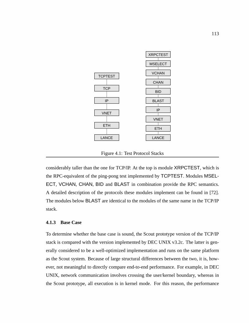
113
TCPTEST
TCP
IP
VNET
ETH
LANCE
VNET
ETH
XRPCTEST
MSELECT
VCHAN
CHAN
BID
BLAST
IP
LANCE
Figure 4.1: Test Protocol Stacks
considerably taller than the one for TCP/IP. At the top is moduleXRPCTEST, which is
the RPC-equivalent of the ping-pong test implemented byTCPTEST. ModulesMSEL-
ECT, VCHAN, CHAN, BID and BLAST in combination provide the RPC semantics.
A detailed description of the protocols these modules implement can be found in [72].
The modules belowBLAST are identical to the modules of the same name in the TCP/IP
stack.
4.1.3 Base Case
To determine whether the base case is sound, the Scout prototype version of the TCP/IP
stack is compared with the version implemented by DEC UNIX v3.2c. The latter is gen-
erally considered to be a well-optimized implementation and runs on the same platform
as the Scout system. Because of large structural differences between the two, it is, how-
ever, not meaningful to directly compare end-to-end performance. For example, in DEC
UNIX, network communication involves crossing the user/kernel boundary, whereas in
the Scout prototype, all execution is in kernel mode. For this reason, the performance
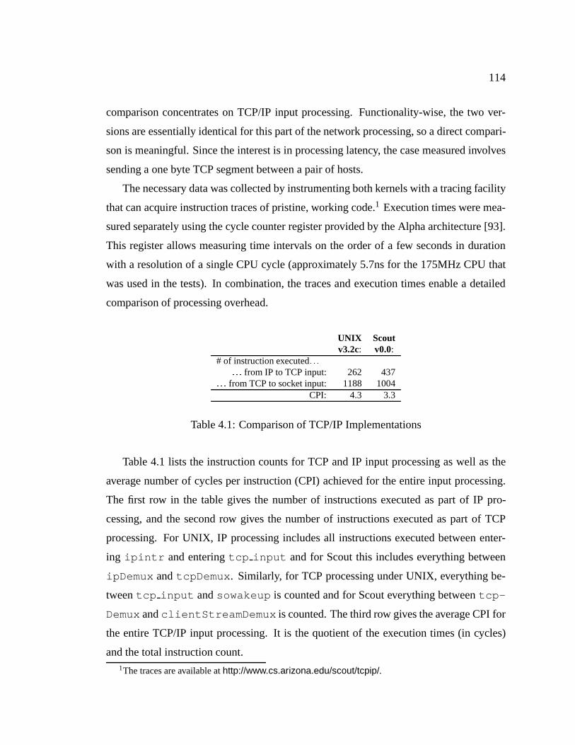
114
comparison concentrates on TCP/IP input processing. Functionality-wise, the two ver-
sions are essentially identical for this part of the network processing, so a direct compari-
son is meaningful. Since the interest is in processing latency, the case measured involves
sending a one byte TCP segment between a pair of hosts.
The necessary data was collected by instrumenting both kernels with a tracing facility
that can acquire instruction traces of pristine, working code.1 Execution times were mea-
sured separately using the cycle counter register provided by the Alpha architecture [93].
This register allows measuring time intervals on the order of a few seconds in duration
with a resolution of a single CPU cycle (approximately 5.7ns for the 175MHz CPU that
was used in the tests). In combination, the traces and execution times enable a detailed
comparison of processing overhead.
UNIX Scoutv3.2c: v0.0:
# of instruction executed: : :: : : from IP to TCP input: 262 437
: : : from TCP to socket input: 1188 1004CPI: 4.3 3.3
Table 4.1: Comparison of TCP/IP Implementations
Table 4.1 lists the instruction counts for TCP and IP input processing as well as the
average number of cycles per instruction (CPI) achieved for the entire input processing.
The first row in the table gives the number of instructions executed as part of IP pro-
cessing, and the second row gives the number of instructions executed as part of TCP
processing. For UNIX, IP processing includes all instructions executed between enter-
ing ipintr and enteringtcp input and for Scout this includes everything between
ipDemux andtcpDemux . Similarly, for TCP processing under UNIX, everything be-
tweentcp input andsowakeup is counted and for Scout everything betweentcp-
DemuxandclientStreamDemux is counted. The third row gives the average CPI for
the entire TCP/IP input processing. It is the quotient of the execution times (in cycles)
and the total instruction count.1The traces are available athttp://www.cs.arizona.edu/scout/tcpip/.
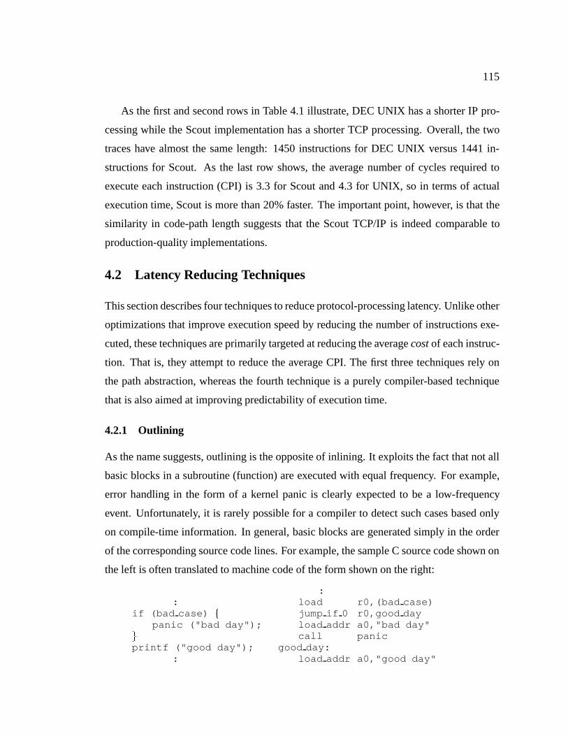
115
As the first and second rows in Table 4.1 illustrate, DEC UNIX has a shorter IP pro-
cessing while the Scout implementation has a shorter TCP processing. Overall, the two
traces have almost the same length: 1450 instructions for DEC UNIX versus 1441 in-
structions for Scout. As the last row shows, the average number of cycles required to
execute each instruction (CPI) is 3.3 for Scout and 4.3 for UNIX, so in terms of actual
execution time, Scout is more than 20% faster. The important point, however, is that the
similarity in code-path length suggests that the Scout TCP/IP is indeed comparable to
production-quality implementations.
4.2 Latency Reducing Techniques
This section describes four techniques to reduce protocol-processing latency. Unlike other
optimizations that improve execution speed by reducing the number of instructions exe-
cuted, these techniques are primarily targeted at reducing the averagecostof each instruc-
tion. That is, they attempt to reduce the average CPI. The first three techniques rely on
the path abstraction, whereas the fourth technique is a purely compiler-based technique
that is also aimed at improving predictability of execution time.
4.2.1 Outlining
As the name suggests, outlining is the opposite of inlining. It exploits the fact that not all
basic blocks in a subroutine (function) are executed with equal frequency. For example,
error handling in the form of a kernel panic is clearly expected to be a low-frequency
event. Unfortunately, it is rarely possible for a compiler to detect such cases based only
on compile-time information. In general, basic blocks are generated simply in the order
of the corresponding source code lines. For example, the sample C source code shown on
the left is often translated to machine code of the form shown on the right:
:: load r0,(bad case)
if (bad case) f jump if 0 r0,good daypanic ("bad day"); load addr a0,"bad day"
g call panicprintf ("good day"); good day:
: load addr a0,"good day"

116
call printf:
The machine code on the right hand side is suboptimal for two reasons: (1) it requires a
jump to skip the error handling code, and (2) it introduces a gap in the i-cache if the block
size is larger than one instruction. A taken jump often results in pipeline stalls and i-cache
gaps waste memory bandwidth because useless instructions are loaded into the cache.
This can be avoided by moving error handling code out of the main line of execution, that
is, byoutliningerror handling code. Such outlined code could, for example, be moved to
the end of the function or to the end of the program where it does not interfere with any
frequently executed code.
Outlining is sometimes used with profile-based optimizers [47, 77]. With profile in-
formation, outlining can be automated relatively easily. However, for the purpose of
experimentation, it is more appropriate to use a language based approach that gives full
and direct control to the programmer. Thus, we modified the GNU C compiler such that
if-statements can be annotated with a static prediction as to whether the if-conditional will
mostly evaluate to true or false. If-statements with annotations will have the machine code
for the unlikely branch generated at the end of the function. Un-annotated if-statements
are translated as usual. With this compiler-extension, the code on the left is translated into
the machine code on the right:
:: load r0,(bad case)
if (bad case @ 0) f jump if not 0 r0,bad daypanic("bad day"); load addr a0,"good day"
g call printfprintf("good day"); continue:
: :return from function
bad day:load addr a0,"bad day"call panicjump continue
Note that the if-conditional is followed by an@0annotation. This tells the modified
compiler that the expression is expected to evaluate to false most of the time. In contrast,
117
the annotation@1would mark a mostly-true expression. For portability and readability,
such annotations are normally hidden in C pre-processor macros calledPREDICT FAL-
SEandPREDICT TRUE.
The above machine code avoids the taken jump and the i-cache gap at the cost of an
additional jump in the infrequent case. Corresponding code is generated for if-statements
with an else-branch. In that case, the static number of jumps remains the same, however.
It is also possible to use such annotations to direct the compiler’s optimizer. For example,
it would be reasonable to give outlined code lower priority during register allocation. The
present implementation does not exploit this option.
Outlining should not be applied overly aggressively as otherwise the reduced locality
and the additional jumps caused by the execution of outlined basic blocks will negate all
potential for performance improvement. In practice, the following three cases appear to
be good candidates for outlining:
1. Error handling. Any kind of expensive error handling can be safely outlined. Error
handling is expensive, for example, if it requires a reboot of the machine, console
I/O, or similar actions.
2. Initialization code. Any code along the critical path of execution that is executed
only once (e.g., at system startup) can be outlined.
3. Conditionally infrequent code. Some code is frequently executed only under certain
circumstances. If those circumstances are not met in a given path, the relevant code
can be outlined.
Note that the first and second cases involve predictions that are independent of any dy-
namic aspects of the way the code is used. In contrast, the third case critically depends
on having dynamic information available. For example, a path used in a latency sensitive
path might outline all unrolled loops, whereas a throughput sensitive path might leave
them inlined. The former makes sense because the latency sensitive case usually involves
so little data processing that unrolled loops are never entered.
The performance results reported in Section 4.3 will show that outlining alone does
not make a tremendous difference in end-to-end processing latency. However, the dy-
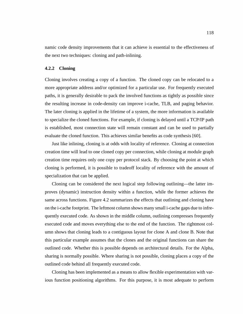
118
namic code density improvements that it can achieve is essential to the effectiveness of
the next two techniques: cloning and path-inlining.
4.2.2 Cloning
Cloning involves creating a copy of a function. The cloned copy can be relocated to a
more appropriate address and/or optimized for a particular use. For frequently executed
paths, it is generally desirable to pack the involved functions as tightly as possible since
the resulting increase in code-density can improve i-cache, TLB, and paging behavior.
The later cloning is applied in the lifetime of a system, the more information is available
to specialize the cloned functions. For example, if cloning is delayed until a TCP/IP path
is established, most connection state will remain constant and can be used to partially
evaluate the cloned function. This achieves similar benefits as code synthesis [60].
Just like inlining, cloning is at odds with locality of reference. Cloning at connection
creation time will lead to one cloned copy per connection, while cloning at module graph
creation time requires only one copy per protocol stack. By choosing the point at which
cloning is performed, it is possible to tradeoff locality of reference with the amount of
specialization that can be applied.
Cloning can be considered the next logical step following outlining—the latter im-
proves (dynamic) instruction density within a function, while the former achieves the
same across functions. Figure 4.2 summarizes the effects that outlining and cloning have
on the i-cache footprint. The leftmost column shows many small i-cache gaps due to infre-
quently executed code. As shown in the middle column, outlining compresses frequently
executed code and moves everything else to the end of the function. The rightmost col-
umn shows that cloning leads to a contiguous layout for clone A and clone B. Note that
this particular example assumes that the clones and the original functions can share the
outlined code. Whether this is possible depends on architectural details. For the Alpha,
sharing is normally possible. Where sharing is not possible, cloning places a copy of the
outlined code behind all frequently executed code.
Cloning has been implemented as a means to allow flexible experimentation with var-
ious function positioning algorithms. For this purpose, it is most adequate to perform
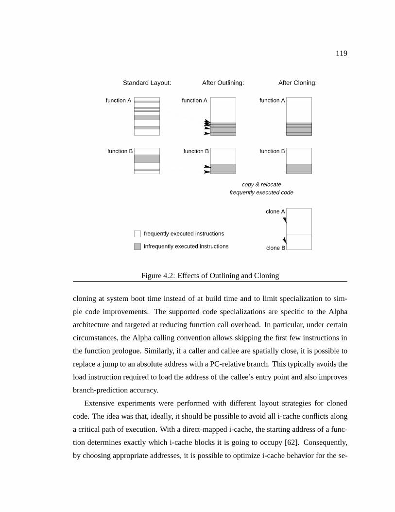
119
clone B
function A
infrequently executed instructions
frequently executed instructions
Standard Layout: After Outlining: After Cloning:
copy & relocatefrequently executed code
function A
function B function B
function A
function B
clone A
Figure 4.2: Effects of Outlining and Cloning
cloning at system boot time instead of at build time and to limit specialization to sim-
ple code improvements. The supported code specializations are specific to the Alpha
architecture and targeted at reducing function call overhead. In particular, under certain
circumstances, the Alpha calling convention allows skipping the first few instructions in
the function prologue. Similarly, if a caller and callee are spatially close, it is possible to
replace a jump to an absolute address with a PC-relative branch. This typically avoids the
load instruction required to load the address of the callee’s entry point and also improves
branch-prediction accuracy.
Extensive experiments were performed with different layout strategies for cloned
code. The idea was that, ideally, it should be possible to avoid all i-cache conflicts along
a critical path of execution. With a direct-mapped i-cache, the starting address of a func-
tion determines exactly which i-cache blocks it is going to occupy [62]. Consequently,
by choosing appropriate addresses, it is possible to optimize i-cache behavior for the se-

120
quence of functions in a given path. The cost is that this fine-grained control of function-
placement occasionally makes it necessary to introduce gaps between two consecutive
functions. Gaps have the obvious cost of occupying main memory without being of any
direct use. More subtly, if i-cache blocks are larger than one instruction, fetching the last
instructions in a function frequently results in part of a gap being loaded into the i-cache
as well, thereby wasting memory bandwidth.
A tool employing simple heuristics was devised that, based on a trace-file, com-
putes a layout that minimizes replacement misses without introducing too many addi-
tional gaps. This approach can be calledmicro-positioningbecause function placement is
controlled down to the size of an individual instruction. I-cache simulation results were
encouraging—the tool made it possible to reduce replacement misses for the TCP/IP path
by an order of magnitude (from 40, down to 4), while introducing only four or five new
cold misses due to gaps.
However, when performing end-to-end measurements, a much simpler layout strategy
consistently outperformed the micro-positioning approach. The simpler layout strategy
achieves abipartite layout. Cloned functions are divided into two classes:pathfunctions
that are executed once andlibrary functions that are executed multiple times per path
invocation. There is very little benefit in keeping path functions in the cache after they
executed, as there is no temporal locality unless the entire path fits into the i-cache. In
contrast, library functions should be kept cached between the first and and last invocation
from a path. Based on these considerations it makes sense to partition the i-cache into
a path partition and a library partition. Within a partition, functions are placed in the
order in which they are called. Such a sequential layout maximizes the effectiveness of
prefetching hardware that may be present. This layout strategy is so simple that it can be
computed easily at runtime—the only dynamic information required is the order in which
the functions are invoked. In essence, computing a bipartite layout consists of applying
the well-known closest-is-best strategy to the library and path partitionindividually [77].
Establishing the performance advantage of the bipartite layout relative to the micro-
positioning approach is difficult since small changes to the heuristics of the latter ap-
proach resulted in large performance variations. The micro-positioning approach usually

121
performed somewhat worse than a bipartite layout and sometimes almost equally well,
but never better. It is not entirely obvious why this is so and it is impossible to make
any definite conclusions without even more fine-grained simulations, but we have three
hypotheses. First, micro-positioning leads to a non-sequential memory access pattern
because a cloned function is positioned wherever it fits best, that is, where it incurs the
minimum number of replacement misses. It may be this nearly random access pattern
that causes the overall slowdown. Second, the gaps introduced by the micro-positioning
approach do cost extra memory bandwidth. This hypothesis is corroborated by the fact
that we have not found a single instance where aligning function entry-points or similar
gap-introducing techniques would have improved end-to-end latency. Note that this is in
stark contrast with the findings published in [43], where i-cache optimization focused on
functions with a very high degree of locality. So it may be that micro-positioning suffers
because of the memory bandwidth wasted on loading gaps. Third, the DEC 3000/600
workstations used in the experiments employ a large second-level cache. It may be the
case that the initial i-cache misses also missed in the second-level cache. On the other
hand, i-cache replacement misses are almost guaranteed to result in a second-level cache
hit. Thus, it is quite possible that 36 replacement misses were cheaper than four or five
additional cold misses introduced by micro-positioning.
Despite the unexpected outcome, the above result is encouraging. It is not necessary
to compute an optimal layout to improve i-cache performance—a simple layout-strategy
such as the bipartite layout appears to be just as good (or even better) at a fraction of the
cost. It must be emphasized that the bipartite layout strategy may not be appropriate if all
the path and library functions fit into the i-cache. If it is likely that the path will remain
cached between subsequent path-invocations, it is better to use a simple linear allocation
scheme that allocates functions strictly in the order of invocation, that is, without making
any distinction between library and path functions. This is a recurrent theme for cache-
oriented optimizations: the best approach for a problem that fits into the cache is often
radically different from the best one for a problem that exceeds the cache size.
122
4.2.3 Path-Inlining
The third latency reducing technique is path-inlining. This is an aggressive form of inlin-
ing where the entire latency-sensitive path of execution is inlined to form a single func-
tion. Consider that a path consists of a sequence of stages. The interfaces in the stages
imply the entire processing that a message undergoes as it traverses a path. If it were pos-
sible to know the sequence of stages in a path at system build time, it would be possible
to prepare optimized code for that path simply by compiling the functions encountered in
the interfaces as a single function. One way to achieve this is to let the system designer
choose what sequences of modules are important, pre-generate code for those important
sequences, and then, at runtime, replace the modular code of a path with the optimized
code. This can be realized using a path transformation rule (see Section 2.2.3.3) whose
guard checks whether or not the sequence of modules in a path matches the sequence of
modules for which a path-inlined function was generated. If so, the function pointers in
the interfaces can be replaced with pointers to the path-inlined version.
Since path-inlining results in code that is specific to a particular sequence of modules,
it is warranted only if the resulting code-path is executed frequently. It is also important to
avoid inlining library-functions: by definition, library-functions are called multiple times
during a single path execution, so it is better to preserve the locality of reference that they
afford. In addition, inlining library-functions would likely lead to an excessive growth in
code size.
The advantage of path-inlining is that it removes almost all call overhead and greatly
increases the amount of context available to the compiler for optimization. For example,
in theVNET module, output processing consists of simply calling the next lower layer’s
output function. With path-inlining, the compiler can trivially detect and eliminate such
useless call overhead.
While path-inlining is simple in principle, the practical problem is quite difficult.
None of the commonly available C compilers are able to inline code across module bound-
aries (object files) and through indirect function calls. Note that inlining through indirect
function calls is made possible by information available from the path that is being opti-

123
mized for. In essence, this is how routing decisions are frozen into the code-path. There
are tools available that assist in cross-module inlining, but the ones that were available
were not reliable enough to be of much use. While it should not be difficult to add path-
information assisted cross-module inlining to an existing C compiler, the path-inlined
versions for the TCP/IP and RPC paths were obtained by manually combining code from
different modules and then using gcc’s normal inlining facility to produce the final code.
For TCP/IP, path-inlining resulted in two large functions: one for input processing and
one for output processing. Roughly the same applies for the RPC stack, although the split
is slightly different: one function takes care of all the processing in protocols XRPCTEST,
MSELECT, VCHAN as well as the output processing in CHAN and the protocols below
it, whereas the other function handles all input processing up to the CHAN protocol.
4.2.4 Last Call Optimization
The fourth and final technique is calledlast call optimization. It does notexploit paths
but instead addresses an issue that frequently arises during path execution, namely deeply
nested call chains. Often, the last action of a partial processing function in a path stage is
to call the processing function of the next stage in the path. This means that each stage
in a path requires additional stack space to store the call frame for the stage’s processing
function. This is often wasteful since, if the call frame of a stage is not accessible to more
deeply nested call frames, it could have been deallocated before calling the next stage.
The last call optimization recognizes such opportunities and avoids wasting stack
space by deallocating stack frames as early as possible. Ideally, in a calling sequence
that is nestedN deep, the amount of stack space used would be just themaximumframe
size among the active functions instead of thesumof the frame sizes. This last call op-
timization is an old technique (e.g., [33]) that is popular with compilers for functional
languages, but not for imperative languages such as C. The main problem with imper-
ative languages is that it is difficult to decide whether or not a callee has access to a
caller’s stack frame. A simple solution is to apply the last call optimization only if none
of the local (automatic) variables have had their addresses taken. This is conservative but
sufficiently accurate to uncover many last call opportunities.
124
A trial-implementation of the last call optimization in gcc showed improvements of up
to 30% for heavily recursive functions. Unfortunately, for the TCP/IP and RPC stacks, it
did not achieve a measurable improvement. There are several likely reasons for this. First,
about half the available last call opportunities were destroyed by the reference counting
scheme that was present in the Scout prototype. Specifically, there were several occasions
where the optimization could have been applied had it not been for the few instructions
required to decrement a reference count after returning from a deeply nested function
call.2 Second, the test programs did not stress stack usage because the tests did not involve
any concurrency. This means that the entire system essentially operated on a single stack
that remained cached across multiple path executions. Third, Section 4.3.3.3 will show
that the TCP/IP and RPC stacks have such poor i-cache behavior on the test system that
the difference due to the last call optimization is not noticeable. On a system with larger
i-caches or with smaller networking stacks, the last call optimization likely would make
a noticeable difference.
4.3 Evaluation
This section evaluates the three path-based techniques presented in the previous section.
It first describes the specific test cases and then follows with a presentation of end-to-end
latency results and a detailed, trace-based analysis of processing behavior. Throughput
measurements are not presented since they would simply confirm that none of the tech-
niques had a measurably negative effect on throughput. In fact, as is commonly the case,
the latency improvements also resulted in a slightly higher throughput.
4.3.1 Test Cases
All measurements are for the environment described in Section 4.1.1. Both TCP/IP and
RPC are measured in several configurations that enable gauging the effect of each tech-
nique. An exhaustive measurement of all possible combinations would have been imprac-
tical, so we focus on the following six version and supply additional data as necessary.
2The current version of Scout implements reference counting at the path level instead of the modulelevel, so this problem has become less of an issue.
125
� STD: This is the Scout prototype base case described in Section 4.1.3. It uses none
of the latency-reducing optimizations described in Section 4.2.
� OUT: Like STD, but uses outlining to eliminate error handling and other basic
blocks that are infrequently executed on the latency-sensitive path.
� CLO: Like OUT, but uses cloning in addition to outlining to achieve a dense i-cache
footprint. A bipartite layout is used to ensure that path-functions do not collide with
library functions.
� BAD: Like CLO, but cloning has been used to artificiallyworsenthe i-cache be-
havior. While not strictly a worst-case scenario, this version is used to establish
the potential of i-cache effects to influence processing latency. Specifically, for the
TCP stack, version BAD results in 217 additional i-cache and 110 additional b-
cache misses (relative to CLO, which has 483 i-cache and 678 b-cache misses). For
the RPC stack, it results in 233 additional i-cache and 14 additional b-cache misses
(relative to CLO with 488 i-cache and 845 b-cache misses).
� PIN: Like OUT, but also uses path-inlining.
� ALL: Like PIN, but cloning with a bipartite layout has been used to improve i-
cache behavior. That is, this version uses all techniques, and is expected to achieve
the best performance.
Note that all versions except STD use path specific code. Thus, it is necessary to lookup
the appropriate path for incoming packets either by using PathIDs [56] or a packet clas-
sifier (such as the one presented in Section 3.4.1). To keep this study independent of
the quality of the classifier, which may well be assisted by hardware, and independent of
whether PathIDs are used, the path lookup costs are excluded from the results presented
in the remainder of this chapter.
4.3.2 End-to-End Results
TCP and RPC latency was measured by ping-ponging packets with no payload between a
server and a client machine. Since TCP is stream-oriented, it does not send any network
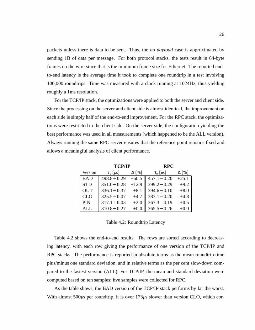
126
packets unless there is data to be sent. Thus, theno payloadcase is approximated by
sending 1B of data per message. For both protocol stacks, the tests result in 64-byte
frames on the wire since that is the minimum frame size for Ethernet. The reported end-
to-end latency is the average time it took to complete one roundtrip in a test involving
100,000 roundtrips. Time was measured with a clock running at 1024Hz, thus yielding
roughly a 1ms resolution.
For the TCP/IP stack, the optimizations were applied to both the server and client side.
Since the processing on the server and client side is almost identical, the improvement on
each side is simply half of the end-to-end improvement. For the RPC stack, the optimiza-
tions were restricted to the client side. On the server side, the configuration yielding the
best performance was used in all measurements (which happened to be the ALL version).
Always running the same RPC server ensures that the reference point remains fixed and
allows a meaningful analysis of client performance.
TCP/IP RPCVersion Te [µs] ∆ [%] Te [µs] ∆ [%]BAD 498.8�0.29 +60.5 457.1�0.20 +25.1STD 351.0�0.28 +12.9 399.2�0.29 +9.2OUT 336.1�0.37 +8.1 394.6�0.10 +8.0CLO 325.5�0.07 +4.7 383.1�0.20 +4.8PIN 317.1�0.03 +2.0 367.3�0.19 +0.5ALL 310.8�0.27 +0.0 365.5�0.26 +0.0
Table 4.2: Roundtrip Latency
Table 4.2 shows the end-to-end results. The rows are sorted according to decreas-
ing latency, with each row giving the performance of one version of the TCP/IP and
RPC stacks. The performance is reported in absolute terms as the mean roundtrip time
plus/minus one standard deviation, and in relative terms as the per cent slow-down com-
pared to the fastest version (ALL). For TCP/IP, the mean and standard deviation were
computed based on ten samples; five samples were collected for RPC.
As the table shows, the BAD version of the TCP/IP stack performs by far the worst.
With almost 500µs per roundtrip, it is over 173µs slower than version CLO, which cor-

127
responds to a slowdown of more than 53%. As explained above, the code in the two
versions is essentially identical. The only significant difference is the layout of that code.
This clearly shows that i-cache effects can have a profound effect on end-to-end latency.
Row STD shows that the regular Scout prototype version of the protocol stacks has a
much better cache behavior than BAD. Compared to the best case, that version is slower
by about 12.9% for TCP/IP and 9.2% for RPC. There are two reasons why STD performs
relatively well. First, earlier experiences with direct-mapped caches led to attempts to
improve cache performance by manually changing the order in which functions appear
within the object files and by changing the link order. Because of such manual tuning, the
STD version has a reasonably good cache behavior to begin with. Second, it also appears
to be the case that the function usage pattern in the Scout prototype is such that laying out
the functions in the address space in what basically amounts to a random manner, yields
an average performance that is closer to the best case than to the worst case. This is es-
pecially true since in the latency sensitive case, there are few loops that have the potential
for pathological cache-behavior. Keep in mind, however, that case BAD is possible in
practice unless the cache layout is controlled explicitly. The techniques proposed in this
chapter provide sufficient control to avoid such a bad layout.
Row OUT indicates that outlining works quite well for TCP/IP—it reduces roundtrip
time by about 15µs compared to STD. Since both the client and the server use outlining,
the reduction on the client side is roughly half of the end-to-end reduction, or 7.5µs. Out-
lining works less well for RPC but is still able to achieve a 4.6µs reduction. This behavior
can be explained by the fact that TCP consists of a few large functions that handle most
of the protocol processing (including connection establishment, tear-down, and packet
retransmission), whereas RPC consists of many small functions that often handle excep-
tional events through separate functions. In this sense, the RPC code is already structured
in a way that handles exceptional events outside the performance critical code path. Nev-
ertheless, outlining does result in significantly improved performance for both protocol
stacks.
In contrast, row CLO indicates that cloning works better for RPC than for TCP. In the
former case, the reduction on the client side is about 11.5µs whereas in the latter case the
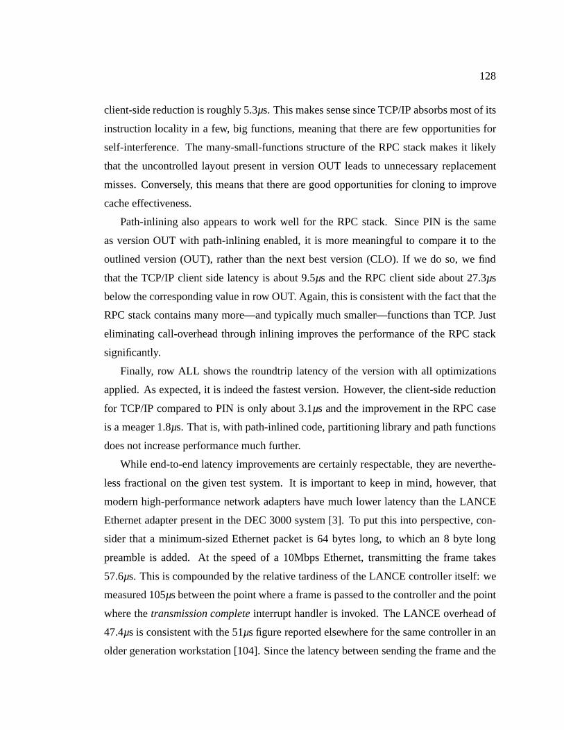
128
client-side reduction is roughly 5.3µs. This makes sense since TCP/IP absorbs most of its
instruction locality in a few, big functions, meaning that there are few opportunities for
self-interference. The many-small-functions structure of the RPC stack makes it likely
that the uncontrolled layout present in version OUT leads to unnecessary replacement
misses. Conversely, this means that there are good opportunities for cloning to improve
cache effectiveness.
Path-inlining also appears to work well for the RPC stack. Since PIN is the same
as version OUT with path-inlining enabled, it is more meaningful to compare it to the
outlined version (OUT), rather than the next best version (CLO). If we do so, we find
that the TCP/IP client side latency is about 9.5µs and the RPC client side about 27.3µs
below the corresponding value in row OUT. Again, this is consistent with the fact that the
RPC stack contains many more—and typically much smaller—functions than TCP. Just
eliminating call-overhead through inlining improves the performance of the RPC stack
significantly.
Finally, row ALL shows the roundtrip latency of the version with all optimizations
applied. As expected, it is indeed the fastest version. However, the client-side reduction
for TCP/IP compared to PIN is only about 3.1µs and the improvement in the RPC case
is a meager 1.8µs. That is, with path-inlined code, partitioning library and path functions
does not increase performance much further.
While end-to-end latency improvements are certainly respectable, they are neverthe-
less fractional on the given test system. It is important to keep in mind, however, that
modern high-performance network adapters have much lower latency than the LANCE
Ethernet adapter present in the DEC 3000 system [3]. To put this into perspective, con-
sider that a minimum-sized Ethernet packet is 64 bytes long, to which an 8 byte long
preamble is added. At the speed of a 10Mbps Ethernet, transmitting the frame takes
57.6µs. This is compounded by the relative tardiness of the LANCE controller itself: we
measured 105µs between the point where a frame is passed to the controller and the point
where thetransmission completeinterrupt handler is invoked. The LANCE overhead of
47.4µs is consistent with the 51µs figure reported elsewhere for the same controller in an
older generation workstation [104]. Since the latency between sending the frame and the
129
receive interrupt on the destination system is likely to be higher, and since each roundtrip
involves two message transmissions, we can safely subtract 105µs�2= 210µs from the
end-to-end latency to get an estimate of the actual processing time involved. For example,
if we apply this correction to the TCP/IP stack, we find that version BAD is actually 186%
slower than the fastest version. Even version STD is still 40% slower than version ALL.
Table 4.3 revisits the end-to-end latency numbers, adjusted to factor out the overhead
imposed by the controller and Ethernet. While there will obviously be some additional
latency, one should expect roundtrip times on the order of 50µs rather than the 210µs
measured on our experimental platform.3
TCP/IP RPCVersion Te [µs] ∆ [%] Te [µs] ∆ [%]BAD 288.8 +186.5 247.1 +59.0STD 141.0 +40.2 189.2 +21.7OUT 126.1 +25.1 184.6 +18.7CLO 115.5 +14.6 173.1 +11.3PIN 107.1 +6.3 157.3 +1.2ALL 100.8 +0.0 155.5 +0.0
Table 4.3: Roundtrip Latency Adjusted for Network and Controller
4.3.3 Detailed Analysis
The end-to-end results are interesting to establish global performance effects, but since
some of the protocol processing can be overlapped with network I/O, they are not directly
related to CPU utilization. Also, it is impossible to control all performance parameters
simultaneously. For example, the tests did not explicitly control data-cache performance.
Similarly, there are other sources of variability. For example, the memory free-list is
likely to vary from test case to test case (e.g., due to different memory allocation patterns
at boot time). While not all of these effects can be controlled, most can be measured.
Towards this end, we collected two additional data sets. The first is a set of instruction
traces that cover most of the protocol processing. The second is a set of fine-grained
3Numbers is this range have been reported in the literature for FDDI and ATM controllers [23].
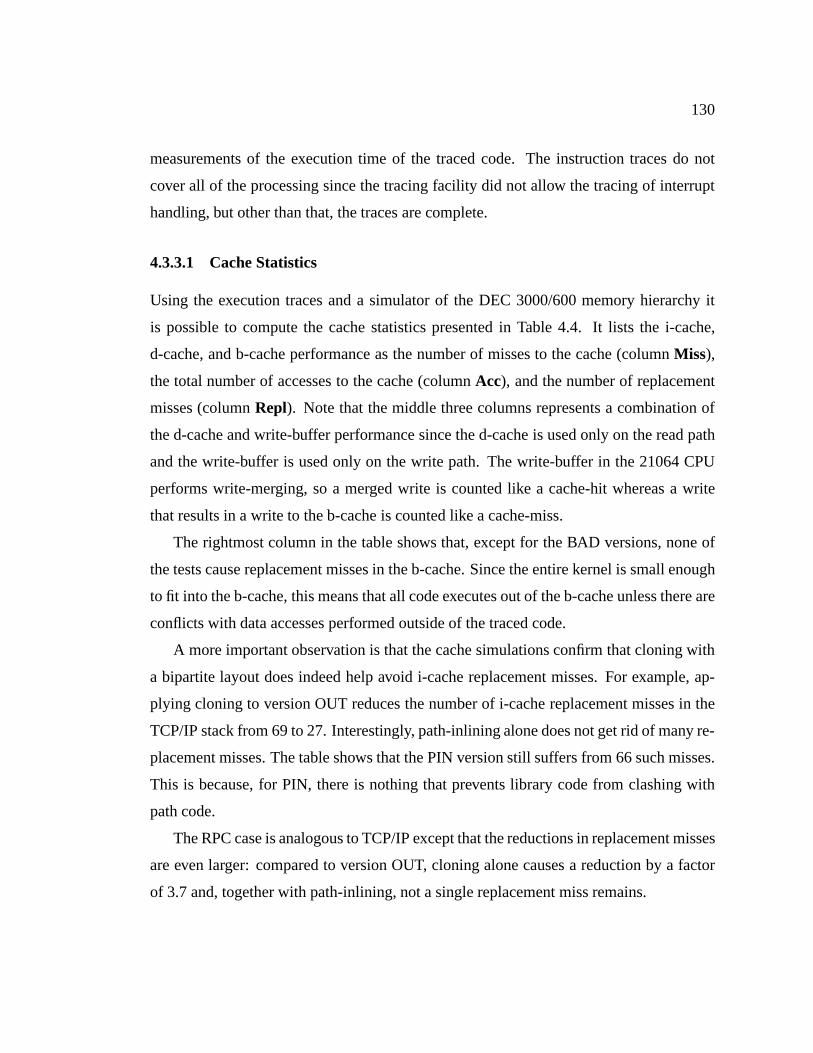
130
measurements of the execution time of the traced code. The instruction traces do not
cover all of the processing since the tracing facility did not allow the tracing of interrupt
handling, but other than that, the traces are complete.
4.3.3.1 Cache Statistics
Using the execution traces and a simulator of the DEC 3000/600 memory hierarchy it
is possible to compute the cache statistics presented in Table 4.4. It lists the i-cache,
d-cache, and b-cache performance as the number of misses to the cache (columnMiss),
the total number of accesses to the cache (columnAcc), and the number of replacement
misses (columnRepl). Note that the middle three columns represents a combination of
the d-cache and write-buffer performance since the d-cache is used only on the read path
and the write-buffer is used only on the write path. The write-buffer in the 21064 CPU
performs write-merging, so a merged write is counted like a cache-hit whereas a write
that results in a write to the b-cache is counted like a cache-miss.
The rightmost column in the table shows that, except for the BAD versions, none of
the tests cause replacement misses in the b-cache. Since the entire kernel is small enough
to fit into the b-cache, this means that all code executes out of the b-cache unless there are
conflicts with data accesses performed outside of the traced code.
A more important observation is that the cache simulations confirm that cloning with
a bipartite layout does indeed help avoid i-cache replacement misses. For example, ap-
plying cloning to version OUT reduces the number of i-cache replacement misses in the
TCP/IP stack from 69 to 27. Interestingly, path-inlining alone does not get rid of many re-
placement misses. The table shows that the PIN version still suffers from 66 such misses.
This is because, for PIN, there is nothing that prevents library code from clashing with
path code.
The RPC case is analogous to TCP/IP except that the reductions in replacement misses
are even larger: compared to version OUT, cloning alone causes a reduction by a factor
of 3.7 and, together with path-inlining, not a single replacement miss remains.
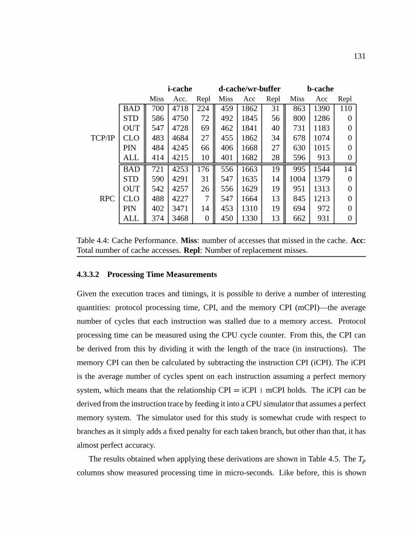
131
i-cache d-cache/wr-buffer b-cacheMiss Acc. Repl Miss Acc Repl Miss Acc Repl
BAD 700 4718 224 459 1862 31 863 1390 110STD 586 4750 72 492 1845 56 800 1286 0OUT 547 4728 69 462 1841 40 731 1183 0
TCP/IP CLO 483 4684 27 455 1862 34 678 1074 0PIN 484 4245 66 406 1668 27 630 1015 0ALL 414 4215 10 401 1682 28 596 913 0
BAD 721 4253 176 556 1663 19 995 1544 14STD 590 4291 31 547 1635 14 1004 1379 0OUT 542 4257 26 556 1629 19 951 1313 0
RPC CLO 488 4227 7 547 1664 13 845 1213 0PIN 402 3471 14 453 1310 19 694 972 0ALL 374 3468 0 450 1330 13 662 931 0
Table 4.4: Cache Performance.Miss: number of accesses that missed in the cache.Acc:Total number of cache accesses.Repl: Number of replacement misses.
4.3.3.2 Processing Time Measurements
Given the execution traces and timings, it is possible to derive a number of interesting
quantities: protocol processing time, CPI, and the memory CPI (mCPI)—the average
number of cycles that each instruction was stalled due to a memory access. Protocol
processing time can be measured using the CPU cycle counter. From this, the CPI can
be derived from this by dividing it with the length of the trace (in instructions). The
memory CPI can then be calculated by subtracting the instruction CPI (iCPI). The iCPI
is the average number of cycles spent on each instruction assuming a perfect memory
system, which means that the relationship CPI= iCPI+mCPI holds. The iCPI can be
derived from the instruction trace by feeding it into a CPU simulator that assumes a perfect
memory system. The simulator used for this study is somewhat crude with respect to
branches as it simply adds a fixed penalty for each taken branch, but other than that, it has
almost perfect accuracy.
The results obtained when applying these derivations are shown in Table 4.5. TheTp
columns show measured processing time in micro-seconds. Like before, this is shown
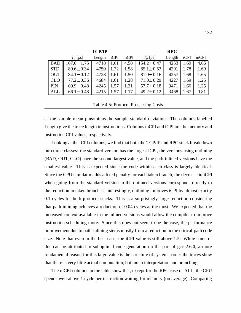
132
TCP/IP RPCTp [µs] Length iCPI mCPI Tp [µs] Length iCPI mCPI
BAD 167.0�1.75 4718 1.61 4.58 154.2�0.47 4253 1.69 4.66STD 89.6�0.34 4750 1.72 1.58 85.1�0.53 4291 1.78 1.69OUT 84.1�0.12 4728 1.61 1.50 81.0�0.16 4257 1.68 1.65CLO 77.2�0.36 4684 1.61 1.28 71.0�0.29 4227 1.69 1.25PIN 69.9�0.48 4245 1.57 1.31 57.7�0.18 3471 1.66 1.25ALL 66.1�0.48 4215 1.57 1.17 49.2�0.12 3468 1.67 0.81
Table 4.5: Protocol Processing Costs
as the sample mean plus/minus the sample standard deviation. The columns labelled
Length give the trace length in instructions. Columns mCPI and iCPI are the memory and
instruction CPI values, respectively.
Looking at the iCPI columns, we find that both the TCP/IP and RPC stack break down
into three classes: the standard version has the largest iCPI, the versions using outlining
(BAD, OUT, CLO) have the second largest value, and the path-inlined versions have the
smallest value. This is expected since the code within each class is largely identical.
Since the CPU simulator adds a fixed penalty for each taken branch, the decrease in iCPI
when going from the standard version to the outlined versions corresponds directly to
the reduction in taken branches. Interestingly, outlining improves iCPI by almost exactly
0.1 cycles for both protocol stacks. This is a surprisingly large reduction considering
that path-inlining achieves a reduction of 0.04 cycles at the most. We expected that the
increased context available in the inlined versions would allow the compiler to improve
instruction scheduling more. Since this does not seem to be the case, the performance
improvement due to path-inlining stems mostly from a reduction in the critical-path code
size. Note that even in the best case, the iCPI value is still above 1.5. While some of
this can be attributed to suboptimal code generation on the part of gcc 2.6.0, a more
fundamental reason for this large value is the structure of systems code: the traces show
that there is very little actual computation, but much interpretation and branching.
The mCPI columns in the table show that, except for the RPC case of ALL, the CPU
spends well above 1 cycle per instruction waiting for memory (on average). Comparing

133
the mCPI values for the various versions, we find that the proposed techniques are rather
effective. Both protocol stacks achieve a reduction by a factor of more than 3.9 when
going from version BAD to version ALL. Even when comparing version ALL to STD we
find that the latter has an mCPI that is more than 35% larger. In terms of mCPI reduction,
cloning with a bipartite layout and path-inlining are about equally effective. The former is
slightly more effective for the TCP/IP stack, but in the RPC case, both achieve a reduction
of 0.4 cycles per instruction. Combining the two techniques does have some synergistic
effects for TCP/IP. The additional reduction compared to outlining or path-inlining alone
is small though, on the order of 0.11 to 0.14 cycles per instruction. Of all the mCPI
values, the value 0.81 for the ALL version of the RPC stack clearly stands out. Additional
measurements that are not reported here lead us to believe that the value is an anomaly:
just small changes to the code resulted in mCPI values more in line with the other results.
This serves as a reminder that while the proposed techniques improve cache behavior, it
is nearly impossible to achieve perfect control for any reasonably complex system.
4.3.3.3 Performance Improvement Comparison
It is now possible to compare the end-to-end results with the processing execution times
and the trace-based cache simulation results. First, we would like to verify that the out-
lining and cloning improvements are really primarily due to i-cache rather than due to
(uncontrolled) d-cache effects. The fact that the mCPI values are much bigger than zero
indicates that the memory system is the bottleneck. As all versions run out of the b-cache
(except for the BAD versions), the processing time improvement is dominated by changes
in the number of b-cache accesses (column∆Nb in Table 4.6). Thus, we would like to
know the percentageI of b-cache access reduction due to the i-cache, as opposed to the
d-cache/write-buffer.4 If the number of b-cache accesses is reduced purely due to the i-
cache, the percentage would be 100%. If the reduction is purely due to the d-cache/write-
buffer, it would be 0%. A value greater than 100% indicates that d-cache/write-buffer
4In computing this percentage, it is important to keep in mind that the number of b-cache accesses dueto the i-cache is given by the number of b-cache accesses minus the number d-cache/write-buffer misses.This is typically greater than the number of i-cache misses since a miss may lead to another i-cache blockbeing prefetched, thus resulting in two b-cache accesses.
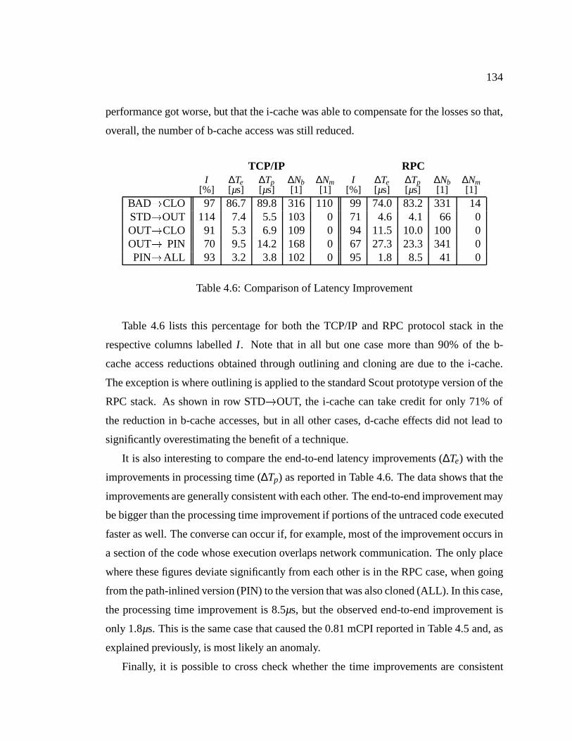
134
performance got worse, but that the i-cache was able to compensate for the losses so that,
overall, the number of b-cache access was still reduced.
TCP/IP RPCI ∆Te ∆Tp ∆Nb ∆Nm I ∆Te ∆Tp ∆Nb ∆Nm
[%] [µs] [µs] [1] [1] [%] [ µs] [µs] [1] [1]BAD!CLO 97 86.7 89.8 316 110 99 74.0 83.2 331 14STD!OUT 114 7.4 5.5 103 0 71 4.6 4.1 66 0OUT!CLO 91 5.3 6.9 109 0 94 11.5 10.0 100 0OUT! PIN 70 9.5 14.2 168 0 67 27.3 23.3 341 0PIN!ALL 93 3.2 3.8 102 0 95 1.8 8.5 41 0
Table 4.6: Comparison of Latency Improvement
Table 4.6 lists this percentage for both the TCP/IP and RPC protocol stack in the
respective columns labelledI . Note that in all but one case more than 90% of the b-
cache access reductions obtained through outlining and cloning are due to the i-cache.
The exception is where outlining is applied to the standard Scout prototype version of the
RPC stack. As shown in row STD!OUT, the i-cache can take credit for only 71% of
the reduction in b-cache accesses, but in all other cases, d-cache effects did not lead to
significantly overestimating the benefit of a technique.
It is also interesting to compare the end-to-end latency improvements (∆Te) with the
improvements in processing time (∆Tp) as reported in Table 4.6. The data shows that the
improvements are generally consistent with each other. The end-to-end improvement may
be bigger than the processing time improvement if portions of the untraced code executed
faster as well. The converse can occur if, for example, most of the improvement occurs in
a section of the code whose execution overlaps network communication. The only place
where these figures deviate significantly from each other is in the RPC case, when going
from the path-inlined version (PIN) to the version that was also cloned (ALL). In this case,
the processing time improvement is 8.5µs, but the observed end-to-end improvement is
only 1.8µs. This is the same case that caused the 0.81 mCPI reported in Table 4.5 and, as
explained previously, is most likely an anomaly.
Finally, it is possible to cross check whether the time improvements are consistent

135
with the reductions in the number of b-cache accesses. If we divide the processing time
improvements (∆Tp) in the second through fifth row by the difference in the number of
b-cache accesses (∆Nb) we get an average b-cache latency in the range from 5.6 to to 17.5
cycles.5 These values appear reasonable considering that a b-cache access takes 10 cycles
to complete. It would be unrealistic to expect exactly 10 cycles per miss since this simple
model ignores many of the finer aspects of the DEC 3000’s memory system. Also, the
same reasoning cannot be applied to the BAD!CLO improvements since the number of
b-cache blocks that remained cached across multiple path invocations was not measured.
Nevertheless, the table includes the data for the sake of completeness. Note that the
PIN!ALL change in the RPC stack yields an 8.5µs processing time improvement, but the
difference in the number of b-cache accesses is only 41. This confirms that the anomalous
improvement cannot be due to the decrease in the number of b-cache accesses since,
otherwise, that would imply that each access cost on the order of 36 cycles—almost four
times the theoretical latency.
4.3.3.4 Outlining Effectiveness
The results presented so far are somewhat misleading in that they underestimate the ben-
efits of outlining. While it does achieve performance improvements in and of itself, it is
also important as an enabling technology for path-inlining and cloning. Thanks to outlin-
ing, the amount of code replication due to path-inlining and cloning is greatly reduced.
Together with this size reduction goes an increase in dynamic instruction density, that is,
less memory bandwidth is wasted loading useless instructions. This can be demonstrated
quantitatively with the results presented in Table 4.7. It shows that without outlining (STD
version), around 20% of the instructions loaded into the cache never get executed. For
both protocol stacks, outlining reduces this by roughly a factor of 1.4. It is illustrative to
consider that a waste of 20% corresponds to 1.8 unused instructions per eight instructions
(one cache block). Outlining reduces this to about 1.3 unused instructions. This is a re-
spectable improvement, especially considering that outlining was applied conservatively.
The table also shows that outlining results in impressive critical-path code-size re-
5Ignoring the anomalous RPC case PIN!ALL and using a conversion factor of 175 cycles/µs.

136
Without Outlining With Outliningi-cache i-cacheunused Size unused Size
TCP/IP 21% 5841 15% 3856RPC 22% 5085 16% 3641
Table 4.7: Outlining Effectiveness
ductions. The Size columns show the static code size (in number of instructions) of the
latency critical path before and after outlining. In the TCP/IP stack, about 1985 instruc-
tions could be outlined, corresponding to 34% of the code. Note that this is almost a
full primary i-cache worth of instructions (8KB). Similarly, in the RPC stack 28% of the
5085 instructions could be outlined. This reinforces the claim that outlining is a useful
technique not only because of its direct benefits, but also as a means to greatly improve
cloning and path-inlining effectiveness. Minimizing the size of the path code improves
cloning flexibility and increases the likelihood that the entire path will fit into the cache.
4.4 Concluding Remarks
This chapter introduced four latency-reducing techniques: one can take advantage of
paths (outlining), two critically depend on paths (cloning and path-inlining), and the
fourth (last call optimization) is targeted at reducing overhead due to the deep call-chains
that are common to path execution. The fourth technique failed to measurably improve
performance in the test environment, but is likely to be beneficial under different circum-
stances, as discussed in Section 4.2.4. The three path-based techniques achieve two kinds
of benefits: first, they improve execution speed by reducing protocol processing latency
and, second, they improve predictability of path execution time by providing explicit con-
trol over critical-path code layout.
The path-based techniques reduce processing latency by improving the memory sys-
tem behavior of the code path, i.e., by reducing the mCPI. Fundamentally, this can be
achieved by (a) increasing the dynamic instruction stream density, (b) reducing the num-
ber of cache conflicts, and (c) reducing the critical-path code size. Each of these com-

137
ponents is addressed by one or more of the techniques presented. Since the gap between
processor and memory speed continues to widen, the techniques are likely to become
even more important in the future. For example, this study was conducted on a machine
with a 175MHz dual-issue Alpha processor and a 100MB/s memory system. Now, sys-
tems with 600MHz quadruple-issue processors and 200MB/s memory systems are readily
available—in other words, the peak execution rate increased by almost a factor of seven,
yet the memory bandwidth increased by only a factor of two.
Predictability is often just as important as raw performance. The proposed techniques
address this issue by enabling reducing fluctuations in execution speed. The BAD case
reported in Section 4.3 demonstrates that an uncontrolled i-cache layout can have a pro-
found effect. Even though this case was constructed artificially, suboptimal configurations
are possible and not are uncommon in practice. For example, the measured mCPI for the
DEC UNIX v3.2c TCP/IP stack is 2.3, which is significantly worse than the 1.58 mCPI
measured for the standard Scout prototype version. The proposed techniques, though not
guaranteeing perfect behavior, avoid such bad i-cache behavior.
138
CHAPTER 5
USING PATHS FOR RESOURCE MANAGEMENT
The greatest of all gifts is the power toestimate things at their true worth.
– La Rochefoucauld
This chapter serves two purposes. First, it provides a concrete example for building
a simple, yet fully functional Scout appliance. The appliance presented is a network-
attached TV that can display MPEG encoded video [54, 67].
Second, this chapter demonstrates path-derived resource management benefits. To
emphasize resource management—as opposed to the path-code related benefits described
in the previous chapter—it is best to choose an appliance that spends most of its CPU
time in just one or a few modules. To this end, MPEG decoding is ideal. This compres-
sion algorithm is capable of reducing the size of a video by a factor of 10 to 100 and
with this high compression ratio comes a relatively expensive decompression algorithm.
Workstations have only recently become fast enough to perform MPEG decoding in real-
time. For example, on a first generation Alpha, it is not atypical that displaying a single
video uses up all available CPU time—ninety percent or more of which is spent in the
MPEG decoder. This means that code-path overhead such as cross-module call overhead
or extraneous operations due to abstraction boundaries are irrelevant for all practical pur-
poses. On the other hand, proper resource management, such as CPU scheduling or buffer
management, is crucial when multiple loads are put on the system simultaneously.
5.1 Building NetTV
This section describes the structure and modules of the NetTV appliance, how paths are
created, and what attributes are involved in path creation. It also provides evidence that
the performance of NetTV is reasonable given the hardware that it is running on.
139
5.1.1 Module Graph
The complete Scout module graph of NetTV is shown in Figure 5.1. A brief explanation
of the modules appearing in this graph is given in Table 5.1. In the figure, each arc is
labelled by the pair of interfaces that are used to communicate along the arc. If this
label contains just a single name, it means that the interface by that name is used to
communicate in both directions (up and down). If the label contains two names separated
by a slash (/ ), the first name refers to the interface used when communicating from the
module above to the one below, and the second refers to the interface used in the reverse
direction. For example, the labelframebuf/hnulli near the arc betweenWiMP andTGA
indicates thatTGA provides aframebuf interface toWiMP and thatWiMP does not
provide an interface toTGA. A description of interfaces appearing in the graph is given
in Table 5.2.
The operation of most modules is readily understood from the descriptions given in
Table 5.1. The MPEG decoder deserves additional attention, however. MPEG expects the
compressed video messages to contain an integral number of MPEG macroblocks. The
number of macroblocks per message is expected to be small enough so that the message
size does not exceed the maximum transmission unit (MTU) of the network link. This
kind of application-level framing (ALF) [16] ensures that the MPEG decoder does not
reach the end of the message in the middle of a complex operation. This simplifies the
MPEG decoder, reduces queuing inside video paths, minimizes the number of context
switches required to process a message, enables integrated layer processing [16], and
enables early load shedding, as will be explained later.
Another aspect of the module graph that may not be entirely obvious is thatSTDIO
is connected toTERM by three separate arcs. The former module implements C standard
I/O library functions such asfopen andprintf in terms of Scout paths. These func-
tions can be called by any other module in the graph and are provided as a convenience
and to facilitate porting existing software to Scout. To implement these services,STDIO
has one service access point that it expects to have at least three connections. The first
connection is used for standard input (stdin ), the second for standard output (stdout ),
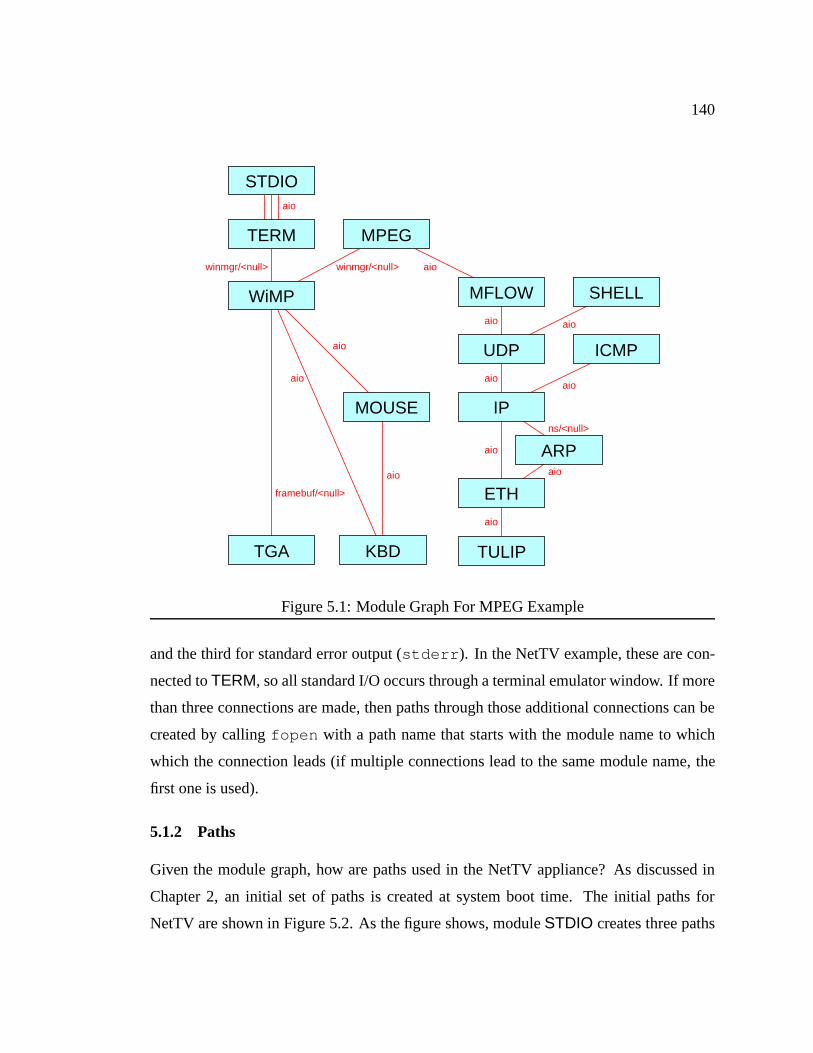
140
aio
framebuf/<null>
aio
ns/<null>
aio
aio
aio
aio
aio
aio
aio
aio
aio
aiowinmgr/<null> winmgr/<null>
TGA TULIP
ETH
ARP
IP
UDP
MFLOW
ICMP
SHELL
MPEGTERM
STDIO
MOUSE
KBD
WiMP
Figure 5.1: Module Graph For MPEG Example
and the third for standard error output (stderr ). In the NetTV example, these are con-
nected toTERM, so all standard I/O occurs through a terminal emulator window. If more
than three connections are made, then paths through those additional connections can be
created by callingfopen with a path name that starts with the module name to which
which the connection leads (if multiple connections lead to the same module name, the
first one is used).
5.1.2 Paths
Given the module graph, how are paths used in the NetTV appliance? As discussed in
Chapter 2, an initial set of paths is created at system boot time. The initial paths for
NetTV are shown in Figure 5.2. As the figure shows, moduleSTDIO creates three paths
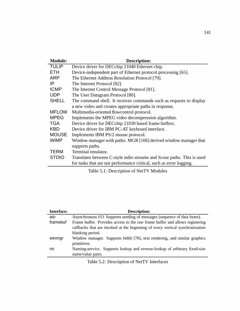
141
Module: Description:TULIP Device driver for DECchip 21040 Ethernet chip.ETH Device-independent part of Ethernet protocol processing [65].ARP The Ethernet Address Resolution Protocol [79].IP The Internet Protocol [82].ICMP The Internet Control Message Protocol [81].UDP The User Datagram Protocol [80].SHELL The command shell. It receives commands such as requests to display
a new video and creates appropriate paths in response.MFLOW Multimedia-oriented flowcontrol protocol.MPEG Implements the MPEG video decompression algorithm.TGA Device driver for DECchip 21030 based frame buffers.KBD Device driver for IBM PC-AT keyboard interface.MOUSE Implements IBM PS/2 mouse protocol.WiMP Window manager with paths: MGR [106] derived window manager that
supports paths.TERM Terminal emulator.STDIO Translates between C-style stdio streams and Scout paths. This is used
for tasks that are not performance critical, such as error logging.
Table 5.1: Description of NetTV Modules
Interface: Description:aio Asynchronous I/O. Supports sending of messages (sequence of data bytes).framebuf Frame buffer. Provides access to the raw frame buffer and allows registering
callbacks that are invoked at the beginning of every vertical synchronizationblanking period.
winmgr Window manager. Supports bitblt [78], text rendering, and similar graphicsprimitives.
ns Naming-service. Supports lookup and reverse-lookup of arbitrary fixed-sizename/value pairs.
Table 5.2: Description of NetTV Interfaces
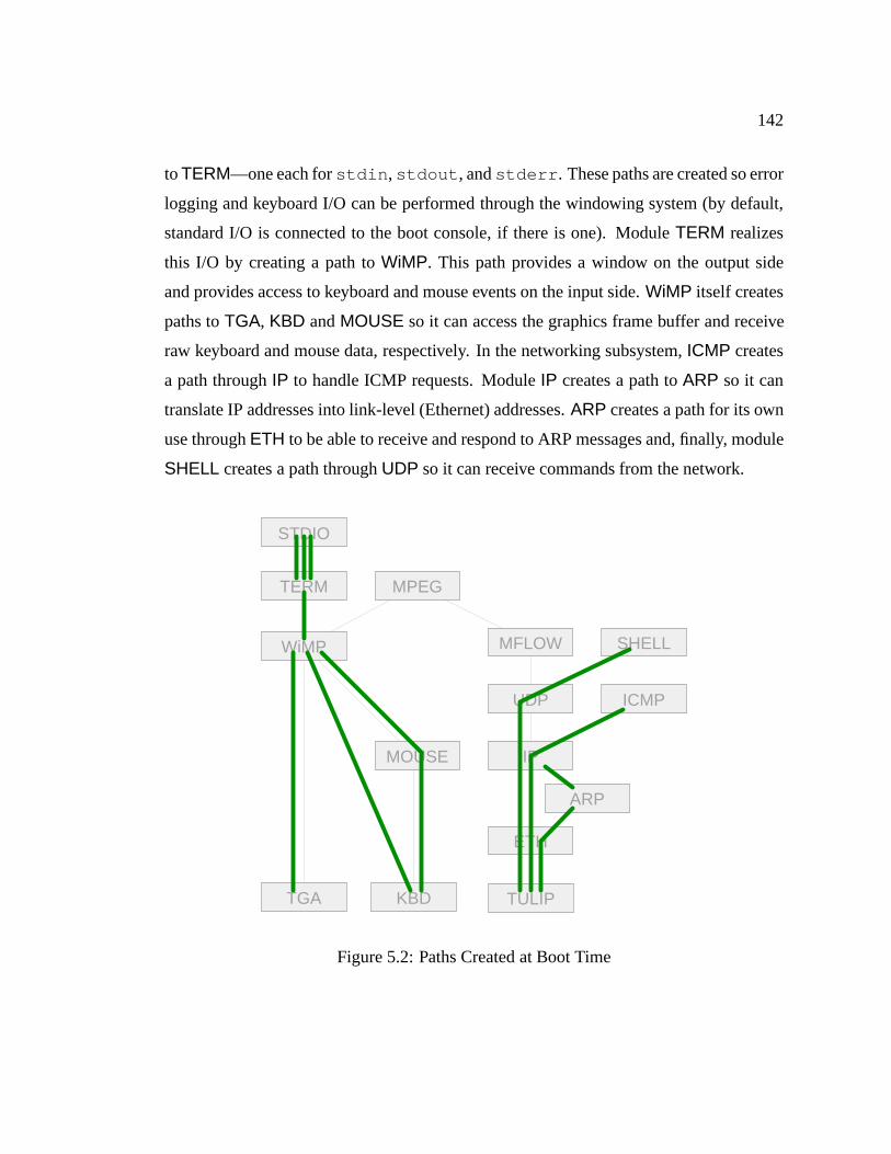
142
toTERM—one each forstdin , stdout , andstderr . These paths are created so error
logging and keyboard I/O can be performed through the windowing system (by default,
standard I/O is connected to the boot console, if there is one). ModuleTERM realizes
this I/O by creating a path toWiMP. This path provides a window on the output side
and provides access to keyboard and mouse events on the input side.WiMP itself creates
paths toTGA, KBD andMOUSE so it can access the graphics frame buffer and receive
raw keyboard and mouse data, respectively. In the networking subsystem,ICMP creates
a path throughIP to handle ICMP requests. ModuleIP creates a path toARP so it can
translate IP addresses into link-level (Ethernet) addresses.ARP creates a path for its own
use throughETH to be able to receive and respond to ARP messages and, finally, module
SHELL creates a path throughUDP so it can receive commands from the network.
WiMP
TERM
STDIO
KBD
MOUSE
MPEG
MFLOW
UDP
IP
TULIP
ARP
ICMP
SHELL
ETH
TGA
Figure 5.2: Paths Created at Boot Time
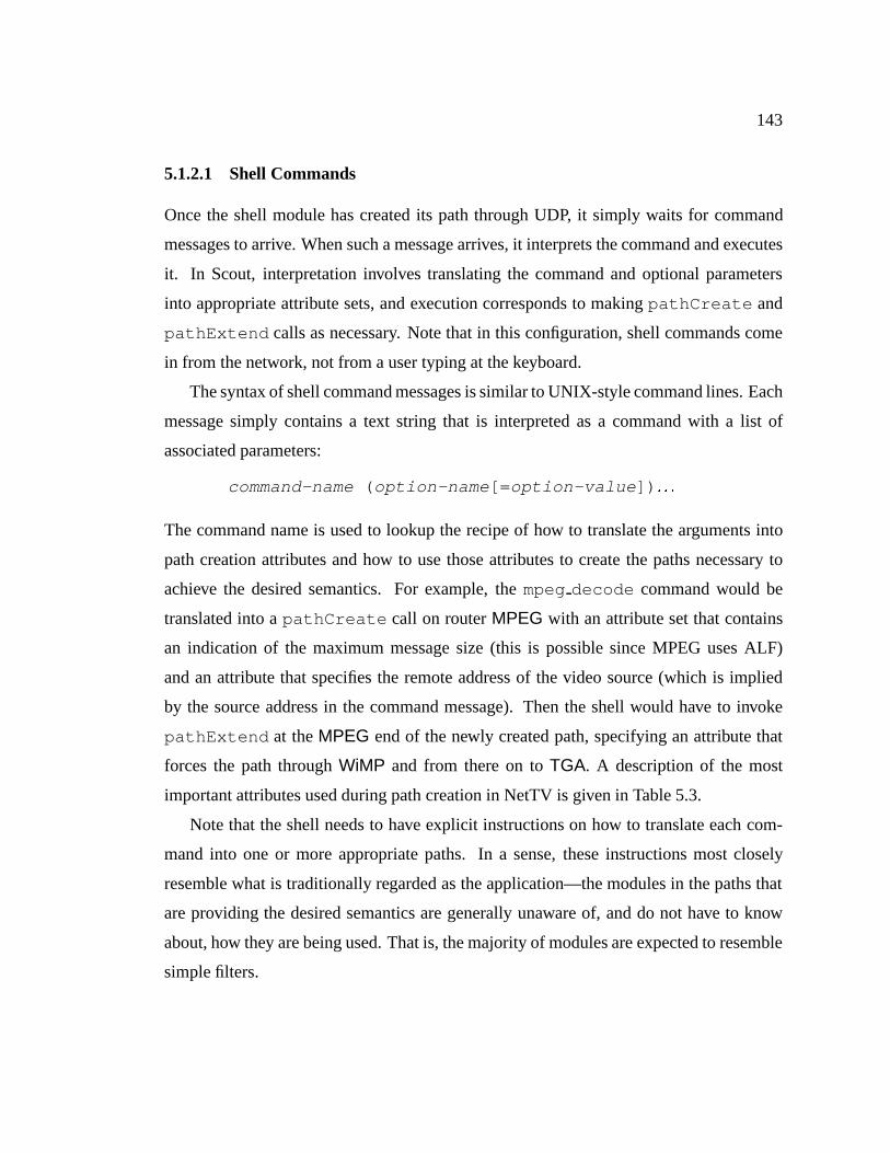
143
5.1.2.1 Shell Commands
Once the shell module has created its path through UDP, it simply waits for command
messages to arrive. When such a message arrives, it interprets the command and executes
it. In Scout, interpretation involves translating the command and optional parameters
into appropriate attribute sets, and execution corresponds to makingpathCreate and
pathExtend calls as necessary. Note that in this configuration, shell commands come
in from the network, not from a user typing at the keyboard.
The syntax of shell command messages is similar to UNIX-style command lines. Each
message simply contains a text string that is interpreted as a command with a list of
associated parameters:
command-name ( option-name [= option-value ]) : : :
The command name is used to lookup the recipe of how to translate the arguments into
path creation attributes and how to use those attributes to create the paths necessary to
achieve the desired semantics. For example, thempeg decode command would be
translated into apathCreate call on routerMPEG with an attribute set that contains
an indication of the maximum message size (this is possible since MPEG uses ALF)
and an attribute that specifies the remote address of the video source (which is implied
by the source address in the command message). Then the shell would have to invoke
pathExtend at theMPEG end of the newly created path, specifying an attribute that
forces the path throughWiMP and from there on toTGA. A description of the most
important attributes used during path creation in NetTV is given in Table 5.3.
Note that the shell needs to have explicit instructions on how to translate each com-
mand into one or more appropriate paths. In a sense, these instructions most closely
resemble what is traditionally regarded as the application—the modules in the paths that
are providing the desired semantics are generally unaware of, and do not have to know
about, how they are being used. That is, the majority of modules are expected to resemble
simple filters.
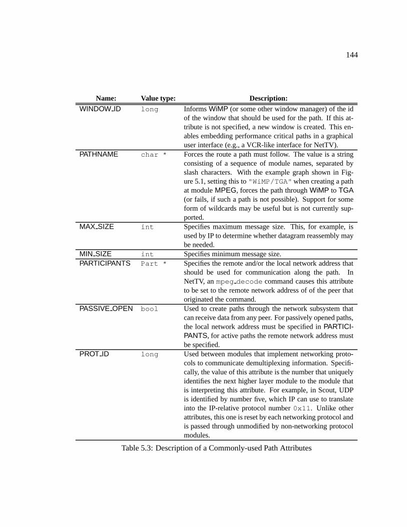
144
Name: Value type: Description:
WINDOW ID long InformsWiMP (or some other window manager) of the idof the window that should be used for the path. If this at-tribute is not specified, a new window is created. This en-ables embedding performance critical paths in a graphicaluser interface (e.g., a VCR-like interface for NetTV).
PATHNAME char * Forces the route a path must follow. The value is a stringconsisting of a sequence of module names, separated byslash characters. With the example graph shown in Fig-ure 5.1, setting this to"WiMP/TGA" when creating a pathat moduleMPEG, forces the path throughWiMP to TGA(or fails, if such a path is not possible). Support for someform of wildcards may be useful but is not currently sup-ported.
MAX SIZE int Specifies maximum message size. This, for example, isused by IP to determine whether datagram reassembly maybe needed.
MIN SIZE int Specifies minimum message size.PARTICIPANTS Part * Specifies the remote and/or the local network address that
should be used for communication along the path. InNetTV, anmpeg decode command causes this attributeto be set to the remote network address of of the peer thatoriginated the command.
PASSIVE OPEN bool Used to create paths through the network subsystem thatcan receive data from any peer. For passively opened paths,the local network address must be specified inPARTICI-PANTS, for active paths the remote network address mustbe specified.
PROT ID long Used between modules that implement networking proto-cols to communicate demultiplexing information. Specifi-cally, the value of this attribute is the number that uniquelyidentifies the next higher layer module to the module thatis interpreting this attribute. For example, in Scout, UDPis identified by number five, which IP can use to translateinto the IP-relative protocol number0x11 . Unlike otherattributes, this one is reset by each networking protocol andis passed through unmodified by non-networking protocolmodules.
Table 5.3: Description of a Commonly-used Path Attributes
145
5.1.2.2 Video Paths
Figure 5.3 shows a typical NetTV video path. One such path is created for each video
to be displayed on the appliance. Each video path starts at the Ethernet device driver
(TULIP), goes through the network subsystem, the flow-control protocol (MFLOW) and
the MPEG decoder, and then through the window manager (WiMP) to the graphics frame
buffer (TGA). For simplicity, only the main queues are shown: the input queue in module
TULIP and the output queue inTGA. Both queues are serviced by interrupt handlers. In
the Ethernet device driver, the queue is filled in response to receive interrupts, and in the
frame buffer module, the output queue is drained in response to interrupts that indicate
the beginning of a vertical synchronization period. Output to the display is synchronized
to this signal because there is no benefit to updating the display at a higher frequency.
There are three points worth emphasizing about these path. First, there are no queues
other than the ones in the device-drivers. As mentioned above, this is due to MPEG’s use
of ALF. Second, ALF—along with explicit paths—enables integrated layer processing.
Since MPEG reads the network messages in units of 32 bits, it would be straight-forward
to integrate the (optional) UDP checksum with the reading of the MPEG data, for exam-
ple. This would require a path-transformation rule that matches MPEG being run over
UDP. If this pattern were to match, the path could be transformed by replacing the UDP
and MPEG receive processing functions with functions that implement the UDP check-
sum computation as part of MPEG’s reading of the packet data. Third, without queuing
in the middle of the path, scheduling is simplified—if the output queue is already full,
there is little point in scheduling a thread to process a packet in the input queue. This
implication would not hold in the presence of additional queues.
5.1.3 Base Performance
It is interesting to compare the base performance of Scout NetTV to a general purpose
operating system running on the same hardware. To this end, Table 5.4 shows the maxi-
mum frame rate that Scout and a Linux-based video decoder can achieve for various short
videos. Along with the maximum frame rates, it also lists the length of the video in num-

146
TERM
STDIO
KBD
MOUSE
MPEG
MFLOW
UDP
IP
TULIP
ARP
ICMP
SHELL
ETH
TGA
WiMP
Figure 5.3: Example Video Paths
ber of frames. All measurements were performed on a first-generation 21064A Alpha
running at 300MHz. The Scout and Linux MPEG-decoder were derived from the same
code base [74], so the only significant difference between the two systems is that Linux
requires a context switch to move a video frame from the MPEG decoder process to the
windowing system (X11). Since almost no time is spent in the networking subsystem,
the performance of that subsystem does not significantly influence overall performance
(in fact, separate measurements yielded roughly the same maximum frame rates when
sourcing the video from the local disk, or more precisely, the disk cache).
As the table shows, the Scout appliance consistently outperforms the Linux based sys-
tem by 20-34%. Of course, this is to be expected given that Linux is a general purpose
system and the Scout appliance is relatively custom built for the purpose. For this reason,
it would not be fair to say Linux is slow (indeed, it performs quite well), but the compar-
ison does show that Scout achieves a performance level that is at least consistent with the
machine it is running on.
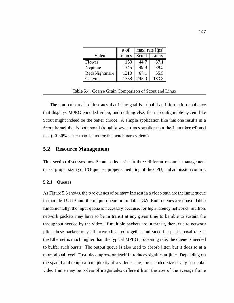
147
# of max. rate [fps]Video frames Scout Linux
Flower 150 44.7 37.1Neptune 1345 49.9 39.2RedsNightmare 1210 67.1 55.5Canyon 1758 245.9 183.3
Table 5.4: Coarse Grain Comparison of Scout and Linux
The comparison also illustrates that if the goal is to build an information appliance
that displays MPEG encoded video, and nothing else, then a configurable system like
Scout might indeed be the better choice. A simple application like this one results in a
Scout kernel that is both small (roughly seven times smaller than the Linux kernel) and
fast (20-30% faster than Linux for the benchmark videos).
5.2 Resource Management
This section discusses how Scout paths assist in three different resource management
tasks: proper sizing of I/O-queues, proper scheduling of the CPU, and admission control.
5.2.1 Queues
As Figure 5.3 shows, the two queues of primary interest in a video path are the input queue
in moduleTULIP and the output queue in moduleTGA. Both queues are unavoidable:
fundamentally, the input queue is necessary because, for high-latency networks, multiple
network packets may have to be in transit at any given time to be able to sustain the
throughput needed by the video. If multiple packets are in transit, then, due to network
jitter, these packets may all arrive clustered together and since the peak arrival rate at
the Ethernet is much higher than the typical MPEG processing rate, the queue is needed
to buffer such bursts. The output queue is also used to absorb jitter, but it does so at a
more global level. First, decompression itself introduces significant jitter. Depending on
the spatial and temporal complexity of a video scene, the encoded size of any particular
video frame may be orders of magnitudes different from the size of the average frame
148
in that stream. Second, the network itself may suffer from significant jitter, e.g., due to
temporary congestion of a network link. The third jitter component is due to the sender
of the MPEG stream. For example, the sender may read the video from a disk drive that
may be accessed concurrently by other tasks.
Since there are queues in each path, an important resource management question is
how big these queues should be. To conserve memory, it is clearly desirable to keep
them as small as possible. This is particularly true for the output queue since each queue
element consists of a complete video frame, which may be quite sizeable (225KB for a
320�240 RGB image). But on the other hand, the queues need to be big enough so that
they can absorb most, if not all jitter normally encountered.
First, consider the input queue. If processing a single packet requires more time than
it takes to request a new packet from the source, then an input queue that can hold two
packets is sufficient: one slot is occupied by the packet currently being processed, and the
second slot is advertised as free to the source. By the time the processing of the current
packet has completed, the next packet will have arrived, and thus, the processor is never
kept idle. On the other hand, if the roundtrip time (RTT) is greater than the time to process
a packet, then the input queue needs to be two times the RTT�bandwidth product of the
network. This relationship is easy to derive, but the intuition behind it is that several
packets need to be grouped together so that the processing time of the packet group is at
least as big as the roundtrip time. Then two slots for such packet groups are required to
keep the network pipe full. This discussion implies that in order to properly size the input
queue, it is necessary to know the relationship between the average roundtrip time and the
average processing time per packet. The roundtrip time can be estimated, for example,
with the algorithm typically used for TCP [50]. For example, in the protocol stack of
NetTV, MFLOW could implement this by putting a timestamp in its packet header and
making available this measured roundtrip time by maintaining a well-known path attribute
(e.g.,AVG RTT), giving the measured average roundtrip time in micro-seconds. Keeping
track of the path execution time is straight-forward as well, especially if the scheduler
maintains a path attribute that specifies the total CPU time accumulated so far. If such
is the case, the average packet processing time can be approximated by the amount by

149
which the accumulated CPU time increases while processing a packet. With this setup, the
Ethernet driver (TULIP) can simply test whether both the average roundtrip time attribute
and the accumulated CPU time attribute are present in the path’s attribute set. If so, it
can use their values to compute the proper queue sizes and resize the queues accordingly.
Note that the path plays two central roles in this application: first, it provides the means to
communicate information (the roundtrip time fromMFLOW toTULIP and the processing
time from the scheduler toTULIP) and second, it enables accurate measuring of the per
packet processing time (since the path extends all the way from the source device to the
sink device).
In the case of the output queue, the factors influencing queue size are more varied
and complex. In theory, it might be possible to compute an appropriate queue size based
on recent observed history. However, the time-scales involved easily reach a range that
is readily noticeable by a human user. Hence, a feedback based algorithm is likely too
slow to be practical. In effect, this means that automatic control of this parameter requires
either distributed paths or a network resource reservation protocol such as RSVP [11] (or
a combination of both). For these reasons, Scout currently leaves this parameter under
user control.
5.2.2 Scheduling
To guarantee proper scheduling, two properties must be satisfied. First, the system must
always execute the highest-priority runnable path. In other words, priority inversion must
be avoided. Second, the scheduling parameters (policy and priority) must computed prop-
erly for each path. Fortunately, paths assist in solving both problems.
5.2.2.1 Avoiding Priority Inversion
In traditional systems, a frequent source of priority inversion is due to queues that are
shared by distinct dataflows. For example, UNIX commonly uses a single queue for all
IP packets. This can cause priority inversion since low-priority IP packets may have to
be processed before a high-priority packet can be discovered and processed. Note that
this problem cannot be solved simply by replacing the shared IP queue with a priority
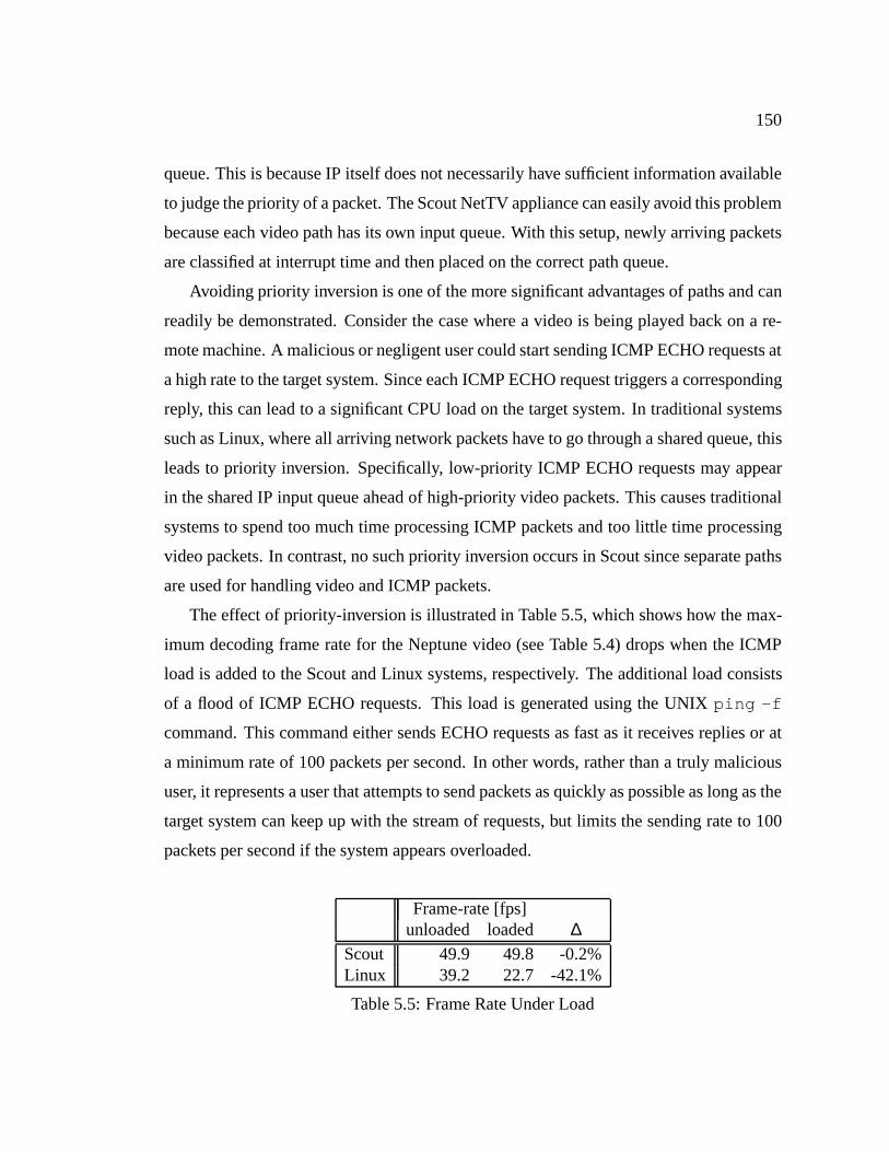
150
queue. This is because IP itself does not necessarily have sufficient information available
to judge the priority of a packet. The Scout NetTV appliance can easily avoid this problem
because each video path has its own input queue. With this setup, newly arriving packets
are classified at interrupt time and then placed on the correct path queue.
Avoiding priority inversion is one of the more significant advantages of paths and can
readily be demonstrated. Consider the case where a video is being played back on a re-
mote machine. A malicious or negligent user could start sending ICMP ECHO requests at
a high rate to the target system. Since each ICMP ECHO request triggers a corresponding
reply, this can lead to a significant CPU load on the target system. In traditional systems
such as Linux, where all arriving network packets have to go through a shared queue, this
leads to priority inversion. Specifically, low-priority ICMP ECHO requests may appear
in the shared IP input queue ahead of high-priority video packets. This causes traditional
systems to spend too much time processing ICMP packets and too little time processing
video packets. In contrast, no such priority inversion occurs in Scout since separate paths
are used for handling video and ICMP packets.
The effect of priority-inversion is illustrated in Table 5.5, which shows how the max-
imum decoding frame rate for the Neptune video (see Table 5.4) drops when the ICMP
load is added to the Scout and Linux systems, respectively. The additional load consists
of a flood of ICMP ECHO requests. This load is generated using the UNIXping -f
command. This command either sends ECHO requests as fast as it receives replies or at
a minimum rate of 100 packets per second. In other words, rather than a truly malicious
user, it represents a user that attempts to send packets as quickly as possible as long as the
target system can keep up with the stream of requests, but limits the sending rate to 100
packets per second if the system appears overloaded.
Frame-rate [fps]unloaded loaded ∆
Scout 49.9 49.8 -0.2%Linux 39.2 22.7 -42.1%
Table 5.5: Frame Rate Under Load

151
In the Scout case, the video path is run at the default round-robin priority, whereas the
path handling ICMP requests is run at the next lower priority.1 In contrast, Linux handles
ICMP and video packets identically up to the point where IP demultiplexes them into
UDP and ICMP packets. As the table shows, adding the ICMP load has little effect on the
frame rate for Scout, while the maximum frame-rate for Linux drops by more than 42%.
Clearly, avoiding priority inversion can have significant benefits. Nevertheless, this is not
to say that paths are the only way to solve this particular problem. For example, both lazy
receiver processing [28] and avoiding receive livelock [68] can have similar benefits. The
point is, however, that the per-path queues in Scout avoid priority inversion naturally and
without requiring any special effort on the part of the system programmer.
5.2.2.2 Scheduling According to Bottleneck Queue
Paths also help ensuring that the right scheduling policy and priority is used to process
video packets. The default Scout scheduler is a fixed-priority, round-robin scheduler.
Since video is periodic, it seems reasonable to use rate-monotonic (RM) scheduling for
MPEG paths [58]. With this approach, priorities are assigned in increasing order of frame
rate and non-realtime paths are given priorities below those of any realtime path. How-
ever, for video, there are several reasons why earliest-deadline-first (EDF) scheduling
more practical:
� The frame-rate should be user-controllable to support slow-motion play and fast for-
warding. This implies that a large and indeed variable number of RM priority-levels
may be necessary. Otherwise, two MPEG paths that have similar, but not identical,
frame-rates could not be distinguished and therefore could not be scheduled prop-
erly. Unfortunately, with a large number of priority levels, RM scheduling is less
efficient than EDF scheduling because for typical implementations, RM scheduling
has a time-complexity that is linear in the number of priority-levels whereas EDF
has a time-complexity that is linear only in the number of runnable threads.
1Round-robin instead of realtime scheduling is used for the video path since the current Scout schedulercannot automatically determine the correct CPU percentage to allocate to the realtime policy. Using ahigher round-robin priority compared to the ICMP path has this effect and is sufficient for the purpose ofthis demonstration.
152
� MPEG decoding is periodic, but not perfectly so. Consider playing a movie at 31Hz
on a machine with a display update frequency of 30Hz. Given that only 30 images
can be displayed every second, it will be necessary to drop one image during each
one second interval. When the drop occurs, there is no need to schedule that path,
so a fixed priority would be suboptimal.
� While not a quantitative argument, probably the strongest case for EDF scheduling
is that it is thenatural choice for a soft realtime thread that moves data from an
input queue to an output queue. For example, if the output queue drains at 30
frames/second and the queue is half full, it is trivial to compute the deadline by
which the next frame has to be produced.
For these reasons, Scout supports EDF scheduling for videos considered important by
the user. As alluded to previously, RM schedulingcouldwork well in a system where the
workload is static (known at system build time). However, in a dynamic system such as
Scout, RM would most likely have to be approximated with a single or just a few priorities
for realtime tasks. If so, it is easy to demonstrate the advantages of EDF scheduling.
For example, using EDF scheduling, Scout can display 8 Canyon movies at a rate of 10
frames per second and a Neptune movie playing at 30 frames per second without missing
any deadlines. The same load performs poorly when using a single round-robin priority
for the realtime tasks: with an output queue size of 128 frames per video path, on the
order of 850 out of 1345 deadlines are missed by the path displaying the Neptune movie.
The reason for this is that the round-robin scheduler keeps allocating CPU time to the
8 Canyon movies as long as their output queues are not full, even though the Neptune
movie may need the CPU more urgently. Of course, this particular example could be
accommodated trivially by using two realtime priorities, but the point is that it is always
possible to construct equivalent examples as long as the number of round-robin priorities
is fixed.
The interesting part of EDF scheduling is how the deadline of video paths is computed.
If path execution is the bottleneck, then the goal should be to keep the output queue as
full as possible. This increases the chance that a video can be displayed without missed

153
deadlines even if some frames transiently overload the CPU. On the other hand, if network
latency is the bottleneck, then the deadline should be based on the state of the input queue.
Since at any given time some number of packets (n) should be in the transit to keep the
network pipe full, the flow control protocol implemented byMFLOW must be able to
advertise an open window of sizen. This means that the deadline is the time at which the
input queue would have less thann free slots. This time can be estimated based on the
current length of the queue and the average packet arrival rate.
Since the path provides direct access to both queues, the effective deadline can simply
be computed as the minimum of the deadlines associated with each queue. Alternatively,
the path could use the path execution time and network roundtrip time to decide which
queue is the bottleneck queue, and then schedule according to the bottleneck queue only.
The latter approach is slightly more efficient, but would require a clear separation between
path execution time and network roundtrip time.
Would scheduling based on the input queue ever make a difference compared to
scheduling according to the output queue? Since the two queues are connected by a
path, whether a scheduling decision can take effect depends on the state of the other, non-
bottleneck queue—output cannot be produced unless input is available and input cannot
be processed unless there is space in the output queue. However, despite this dependency,
scheduling according to the bottleneck queue would make a difference for video paths.
This is because there is not a simple one-to-one correspondence between input packets
and output frames. The MPEG module effectively processes and then buffers incoming
packets until a full output frame has been reassembled. Thus, scheduling according to the
input queue would tend to process packets as soon as they arrive, which would help to
keep the network pipe full. In contrast, scheduling according to the output queue would
tend to cluster packet processing since incoming packets would be queued up until an out-
put slot becomes available. This clustering (batching) would improve the effectiveness of
the memory system and therefore effectiveness of the CPU at a time when CPU cycles
are at a premium—certainly a desirable property.
154
5.2.3 Admission Control
Paths are also useful to decide whether or not a new video path should be admitted to the
system. Admission control involves testing whether sufficient resources are available for a
new path. The primary resources of concern are memory, CPU cycles, and I/O bandwidth.
Since each path has a unique id, it is trivial to account for memory consumption on a per-
path basis. While, in general, it is difficult to predict memory requirementsa priori, it is
easy to create a path and let it execute as long as it remains within the memory constraints
set by the admission policy. This is particularly practical since experience indicates that
many paths require little or no dynamic memory allocation once they are fully established.
Thus, should a path exceed its memory limits, this fact will typically be discovered during
path creation time.
Deciding admissibility with respect to CPU load is more difficult since by the time
CPU overload is detected it may be too late for corrective actions. MPEG encoded videos
make the problem especially difficult since the decoding time per frame is highly variable.
Fortunately, there appears to be a fairly good correlation between the average frame size
in a video and the average decoding time per video frame. For example, the correlation
for a selection of fourteen video clips is shown in Figure 5.4. The selection includes
commercials, cartoons, and scenes from feature-length movies. The frame type sequences
and graphical resolution also varies widely. The graph shows the average decoding time
in seconds per frame as a function of the average frame size of each clip. Each data point
is represented by a small diamond shaped marker and the sample points are connected by
a solid line. In addition to this raw data, a linear regression curve is shown as a dashed
line. TheR2 coefficient of the linear regression through the fourteen sample points is only
0.78 and the graph shows that there certainly is quite some variability. On the other hand,
it appears that the correlation is good enough to be useful for making at least a rough
estimate as to whether a new video path could be accommodated or not.
The parameters of the linear regression depend on the CPU type, clock rate, cache
sizes, graphics card, and so on, and are therefore highly system dependent. Rather than
laboriously deriving the parameters for each platform, it would seem more appropriate to

155
0.002
0.004
0.006
0.008
0.01
0.012
0.014
0.016
5000 10000 15000 20000 25000 30000 35000 40000 45000
Dec
odin
g tim
e [s
ec]
Framesize [bits]
dithertime/pixel=1.02e-07, intercept=0.000173404, slope=3.11173e-07, R^2=0.775904
line 1line 2
Figure 5.4: Correlation Between MPEG Frame Size and Decoding Time
compute the parameters online as videos are being played back. This, again, is made easy
by the fact that it is straight-forward to keep track of the per-path execution time.
Yet another path application comes into play when the admission control determines
that a given video cannot be accommodated. At that point, a user may choose to view
the video with degraded quality. For example, the user may request that only every third
image be displayed. Thanks to ALF and early demultiplexing, this could be realized by
a special classification filter that drops all packets except for those whose frame number
is an integer multiple of three. In other words, paths make it possible to shed load at the
earliest possible point within the system. Dropping the frames directly at the source may
be an even better solution, but this is possible only if the video is transmitted point-to-
point, not via multicast.
Admission control of the final resource of interest—I/O bandwidth—benefits from
paths since device-to-device paths such as the video paths identify which devices are

156
used. For video paths, the necessary network bandwidth and graphics adapter bandwidth
can be computed relatively easily based on the geometric size of the video, its frame rate,
and the average size of an encoded frame. Hence, to decide whether a newly created path
should be admitted, the admission control policy would simply have to check whether
enough bandwidth is remaining both for the source and the sink device of the path.
157
CHAPTER 6
CONCLUSIONS
Si finis bonus est, totum bonum erit.(If the end be well, all is well.)
– Gesta Romanorum (Tale LXVII)
6.1 Summary
This dissertation presents the Scout operating system architecture, which is oriented to-
wards communication-oriented systems in general, and information appliances in partic-
ular. A cornerstone of this architecture is a new abstraction called thepath, which can
be viewed as a vertical slice through a modular system. Paths are complementary to, and
just as fundamental as, modular system design. They are modeled after virtual circuits
in communication networks, and hence, can be viewed as bidirectional dataflows. Since
data processing inside a system is considerably richer than the processing that occurs
along a virtual circuit in a traditional (passive) communication network, paths are signif-
icantly more complex and versatile. Owing to this necessary flexibility, it just as natural
to view paths as processing pipe-lines, paths of execution, resource accounts, or loci of
identity. No one view is technically more correct than the others, but depending on the
context in which paths are applied, choosing the right view often simplifies developing an
appropriate mental model.
The path abstraction enables building efficient communication-oriented systems be-
cause it encapsulates performance critical dataflows and the processing along those flows
across multiple module boundaries. By crossing multiple modules, a path enables global
optimizations that are typically difficult or impossible to realize in strictly modular sys-
tems. The same encapsulation also enables using paths as the building blocks to re-
158
alize systems that provide quality-of-service guarantees that are difficult to realize in
purely modular systems. In essence, paths make it easy to distinguish between differ-
ent dataflows in the system and to monitor and control their behavior.
Scout is a modular architecture that employs paths as the primary means to com-
municate data through a system. Using just a single communication abstraction greatly
simplifies the programming model as it relieves system designers from having to choose
from similar yet sometimes conflicting abstractions. Paths are passive entities (data-lanes)
through which data is shepherded by threads. Scout defines a simple but flexible execution
model that avoids deadlock and depends on higher-level mechanisms to bound resource
consumption due to threads. Most of the time, the path that should be used to transmit or
receive data is known from context. To accommodate the other case, where the appropri-
ate path is implied by the contents of the data itself, Scout supports a packet classification
scheme that is both modular and efficient. Systems that employ classifiers without paths
typically cause a duplication of all demultiplexing decisions, since the classifier has to
make the decisions to find the right place to deliver the message to, but then the same
classification decisions have to be repeated as part of the regular data processing. Scout is
able to avoid such duplication since the demultiplexing decisions are represented explic-
itly in the path as a sequence of stages.
To validate the basic architecture, this dissertation studies two of the potential appli-
cations of paths. The first study investigates paths as a mechanism to improve networking
subsystem performance and the second study investigates paths as a mechanism to im-
prove resource management in a networked television appliance (NetTV). The NetTV
study also provides a concrete example for building a simple yet useful information ap-
pliance with Scout.
The networking subsystem study tests three path-based optimization techniques—
outlining, cloning, and path-inlining—on both a TCP/IP and an RPC protocol stack.
The techniques are primarily targeted at improving the memory system behavior of the
latency-sensitive paths that occur when processing small packets. The techniques are
able to achieve significant improvements in latency and dramatic reductions in the aver-
age number of cycles that a CPU is stalled due to the memory system.
159
In contrast, the structure of the NetTV appliance is such that the overhead due to
module boundaries is not an overriding concern. However, since displaying video is a
complex and computationally expensive soft realtime task, proper resource management
is essential to providing appropriate quality-of-service. The study shows that paths can
assist in solving such resource management problems in an efficient and easy manner.
6.2 Contributions
This dissertation supports the claim that information appliances and communication-
oriented systems in general require and benefit from novel operating system concepts.
The path abstraction and Scout’s demultiplexing scheme are just two examples discussed
in this dissertation that are novel concepts designed specifically with the needs of infor-
mation appliances in mind. This is not to say that these concepts are necessarily limited to
appliances, or that they would not have been conceived without appliances, but the needs
of appliances at least fostered their invention. The ultimate truth of the claim can only be
evaluated as a function of the success or failure that information appliances experience in
the long term.
The dissertation establishes that paths can be evolved into a fundamental abstraction.
In Scout, paths are the only means to communicate, in a controlled fashion, data between
an arbitrary module pair. Paths also have been shown to be efficient, general, and useful.
The generality of paths derives from the fact that they can be so short that a Scout system
can degenerate into a traditional modular system. Such a degenerate system is certainly
not optimal with respect to performance or resource management, but it ensures that any
modular system can be built with Scout. The two validation studies presented in this
dissertation suggest that paths are useful both to optimizing the processing along a path,
as well as to ensure proper resource management on a per path basis. Micro- and macro-
benchmarks show that paths do not incur undue space or time overhead and often help
improving system performance. In other words, Scout paths are efficient and light-weight.

160
6.3 Future Directions
As discussed earlier, this dissertation establishes the basic Scout and path architecture and
provides initial evidence that the architecture is indeed appropriate for communication-
oriented appliances. At the same time, it leaves many questions unanswered. For ex-
ample, exactly what kinds of path invariants are meaningful and exploitable in different
subsystems, and what tools can be used to exploit these invariants certainly warrants fur-
ther research. Similarly, the usefulness of quasi-invariants likely deserves more attention.
For the networking subsystem, there are cases where quasi-invariants could be beneficial,
and the same is expected to be true for other parts of the system as well. For example, IP
routing information changes infrequently relative to the life time of paths, but since that
information is not guaranteed to remain constant, the current Scout system does not permit
paths that depend on IP routing information to extend beyond IP. With quasi-invariants,
it would be trivial to avoid this limitation. However, whether or not the advantages due
to quasi-invariants would outweigh the additional complexity they introduce is not obvi-
ous. To answer such questions, it is necessary to collect more experience in designing,
building, and studying actual appliances that span a wide range of applications. A few
examples are discussed next.
� IP router: An IP router supporting different quality-of-service on a per-flow basis
can exploit paths to ensure proper resource management for each flow.
� Active network node: Using Scout to implement nodes in an active network [103]
allows efficient forwarding of passive packets, yet flexible processing of active
packets. The modularity of Scout should also make it easy to quickly adapt to
different hardware and facility experimentation with different processing engines.
� Scalable storage server node:A variety of path-based benefits are imaginable for
the disk subsystem. For example, it might be useful to associate one of the data
access patterns identified by Cao et al. [12] with each path that traverses the disk
subsystem. The access pattern of a path could be used by the modules in the disk
subsystem to select an appropriate caching policy. Also, code-optimization tech-
161
niques could be used to improve the performance of small reads or writes [85]. As
a final example, paths through the disk subsystem could prove useful in schedul-
ing disk accesses in a manner that will ensure a certain level of quality-of-service
for the path. Employing Scout to build the nodes in a scalable storage server or
network-attached disks would provide an ideal target to study such path applica-
tions.
� Web server: Building a web server with Scout is interesting for two reasons. First,
Scout paths should make it possible to build powerful web servers based on com-
modity hardware and adequate web servers based on minimum cost appliances
(such as network-attached thermometers). Second, paths should also enable pro-
viding differentiated service to the various classes of customers.
� Network firewall: Building a firewall based on general purpose operating system
makes guaranteeing correctness and safety a difficult problem. A Scout system
could facilitate this task because its modular structure enables solving the problem
with the smallest possible number of modules, which minimizes the amount of code
that would have to be proven secure. Similar to the IP router example, paths could
be used to separate dataflows with distinct security requirements.
� Network camera: Combining NetTV with a remote network camera makes it pos-
sible to study and exploit paths in a truly end-to-end environment. This is partic-
ularly interesting in a setting that involves intermediate routers that either support
active computation or at least distinct levels of quality-of-service.
� Mobility: Appliances such as personal information managers will be used in a
roaming mode and will therefore be connected a communication network on an in-
termittent basis only. Handling intermittent connectivity typically requires support
from higher-level and often application-specific software [75], but studying such
appliances should also provide interesting insights on the path architecture. For ex-
ample, the role of quasi-invariants could be significantly more important on mobile
appliances than on stationary ones.
162
6.3.1 CPU Scheduling
Scout focuses on information appliances which implies that both soft realtime and non-
realtime tasks need to be accommodated, that tasks are created dynamically at runtime,
and that the CPU scheduler should be able to operate well in a mostly autonomous fashion.
The requirement of autonomous operation is due to the fact that appliances should not rely
on a sophisticated user that ensures a given task mix is reasonable. This is because either
the user is not sophisticated, does not want to worry about such menial tasks, or does not
exist at all (e.g., in case of a remote operated appliances).
Finding an appropriate soft realtime scheduler is difficult because, unlike many hard
realtime schedulers, it must be fairly general. For example, it cannot assume that syn-
chronization constraints within a task are trivial or negligible. Non-trivial synchronization
makes it difficult to employ planning-based approaches, such as the one presented in [53].
On the other hand, if a user is committed to a certain realtime task, then it probably would
not be acceptable if starting another unrelated task, which may not even be a realtime
task, would cause the realtime task to start to misbehave. The desire to support at least
a certain level of fate isolation makes it difficult to use fair share based schedulers such
as the one presented in [70]. At the same time, hierarchical schedulers such as the ones
presented in [36, 41] are not of much help since realtime scheduling by its very nature is
not hierarchical (time is absolute).
On the positive side, it should be possible to exploit the relatively simple linear struc-
ture of paths to improve scheduling decisions. For example, for I/O bound tasks the size
of the input and output queues convey important information. Similarly, average path
execution time and related quantities should help in solving the scheduling problem.
Aside from finding an appropriate scheduling mechanism, the question of finding a
useful, easy to understand policy is crucial in its own right. Many sophisticated schedul-
ing mechanism make use of priorities, deadlines, latency tolerances, and various other pa-
rameters. In an appliance-like environment, a policy would be required that could derive
these parameters either fully automatically, based on observing (remote) user behavior, or
based on simple hints by the user.
163
6.3.2 Distributed Paths
At present Scout paths do not extend beyond the boundary of a single system. Extend-
ing paths to cover end-to-end data flows even when distributed across multiple systems
is both a logical and useful step. For example, distributed paths are necessary to provide
truly end-to-end quality-of-service assurances. Distributed paths are particularly impor-
tant when operating in a wide-area network where network bandwidth and latency are
often the limiting factors to overall performance.
Distributed paths are likely to be realizable on top of existing Scout paths and cor-
responding network concepts, such as flows [11]. The more interesting questions relate
to how path creation should be controlled in a distributed environment. For example,
the source and destination machines may want to coordinate the values for certain path
invariants (e.g., maximum packet size or throughput may depend on the network connec-
tion being used). Thus, new networking protocols may be needed to support exchanging
such meta-path information.
An interesting observation is that Scout paths and the virtual circuits they are mod-
eled after appear to be on a course of convergence. Research in active networks [103]
effectively makes it, at least theoretically, possible to build network routers that perform
processing as complex as that in Scout modules. It is therefore fully expected that Scout
distributed paths will be able to leverage off of research in active networks and vice versa.
6.3.3 Secure Paths
Scout paths encapsulate dataflows. Since the task of a secure system is often to safe-guard
dataflows, it appears that Scout paths could provide a natural foundation for building se-
cure systems. Securing data flows could occur at two levels: in a distributed environment
where each individual Scout machine executes code that is trusted or within a single Scout
machine where there is a certain level of internal mistrust. The latter would require adding
mechanisms to Scout to enforce the safety of paths, such as hardware protection domains
or sand-boxing [95].
164
REFERENCES
[1] Mark B. Abbott and Larry L. Peterson. Increasing network throughput by inte-grating protocol layers. IEEE Transactions on Networking, 1(5):600–610, Octo-ber 1993.
[2] Mark Bert Abbott. A Language-Based Approach to Protocol Implementation.PhD thesis, Department of Computer Science, University of Arizona, Tucson, AZ85721, 1993.
[3] AMD. Am7990: Local Area Network Controller for Ethernet.
[4] Ken Arnold and James Gosling.The Java Programming Language. Addison-Wesley, Reading, MA, 1996. ISBN 0-201-63455-4.
[5] Mary L. Bailey, Burra Gopal, Michael A. Pagels, Larry L. Peterson, and PrasenjitSarkar. PathFinder: A pattern-based packet classifier. InProceedings of theFirst Symposium on Operating Systems Design and Implementation, pages 115–123, Monterey, CA, 1994. ACM/USENIX.ftp://ftp.cs.arizona.edu/xkernel/Papers/pathfinder.ps.
[6] David Banks and Mike Prudence. A high performance network architecture fora PA-RISC workstation. IEEE Journal on Selected Areas in Communication,11(2):191–202, February 1993.
[7] Brian N. Bershad, Stefan Savage, Przemyslaw Pardyak, Emin G¨un Sirer, Marc E.Fiuczynski, David Becker, Craig Chambers, and Susan J. Eggers. Extensibility,safety and performance in the SPIN operating system. InProceedings of the Fif-teenth ACM Symposium on Operating System Principles, pages 267–284, CopperMountain Resort, CO, December 1995. ACM.
[8] Edoardo Biagioni. A structured TCP in standard ML. InProceedings of SIG-COMM ’94 Symposium, pages 36–45, London, England, August 31st–September2nd 1994. ACM.http://www-cgi.cs.cmu.edu/afs/cs/project/fox/mosaic/papers/sigcomm94.ps.
[9] Joel Birnbaum. How the coming digital utility may reshape computing andtelecommunications, October 1996.http://www.hpl.hp.com/management/speeches/ieee.htm.

165
[10] Trevor Blackwell. Speeding up protocols for small messages. InProceedingsof SIGCOMM ’96 Symposium, pages 85–95, Stanford, CA, August 1996. ACM.http://www.acm.org/sigcomm/sigcomm96/papers/blackwell.html.
[11] R. Braden, D. Clark, and S. Shenker.Integrated Services in the Internet Architec-ture: an Overview. DARPA, June 1994.http://ds.internic.net/rfc/rfc1633.txt.
[12] Pei Cao, Edward W. Felten, and Kai Li. Implementation and performance ofapplication-controlled file caching. InProceedings of the First Symposium onOperating Systems Design and Implementation, pages 165–177, Monterey, CA,1994. ACM/USENIX.ftp://ftp.cs.princeton.edu/pub/people/pc/OSDI94/paper.ps.Z.
[13] L. Cardelli, J. Donahue, L. Glassman, M. Jordan, B. Kalsow, and G. Nelson.Modula-3 language definition.SIGPLAN Notices, 27(8):15–42, August 1992.
[14] C. Castelluccia, W. Dabbous, and S. O’Malley. Generating efficient protocolcode from an abstract specification. InProceedings of SIGCOMM ’96 Sympo-sium, pages 60–71, Stanford, CA, August 1996.http://www.acm.org/sigcomm/sigcomm96/papers/castelluccia.html.
[15] Chran-Ham Chang, Richard Flower, John Forecast, Heather Gray, William R.Hawe, K. K. Ramakrishnan, Ashok P. Nadkarni, Uttam N. Shikarpur, and Kath-leen M. Wilde. High-performance TCP/IP and UDP/IP networking in DECOSF/1 for Alpha AXP. Digital Technical Journal, 5(1):44–61, Winter 1993.
[16] David Clark and David Tennenhouse. Architectural considerations for a new gen-eration of protocols. InProceedings of SIGCOMM ’90 Symposium, pages 200–208, Philadelphia, PA, September 1990. ACM.
[17] David D. Clark. The design philosophy of the DARPA Internet protocols. InProceedings of SIGCOMM ’88 Symposium, pages 106–114, Stanford, CA, August1988. ACM.
[18] David D. Clark, Van Jacobson, John Romkey, and Howard Salwen. An analysisof TCP processing overheads.IEEE Communications Magazine, 27(6):23–29,June 1989.
[19] Raymond K. Clark, E. Douglas Jensen, and Franklin Reynolds. An architec-tural overview of the Alpha real-time distributed kernel. InProceedings of theUSENIX Workshop on Micro-Kernels and Other Kernel Architectures, pages 127–146, Seattle, WA, April 1992.

166
[20] Doug Cooper. Standard Pascal User Reference Manual. W. W. Norton & Com-pany, New York, NY, 1983. ISBN 0-393-30121-4.
[21] Fernando J. Corbat´o, M. Merwin-Daggett, and Robert C. Daley. An experimentaltime-sharing system. InProceedings of the AFIPS Spring Joint Computer Con-ference, pages 335–344, May 1962.
[22] Robert C. Daley and Jack B. Dennis. Virtual memory, processes, and sharing inMULTICS. Communications of the ACM, 11(5):306–312, May 1968.
[23] Chris Dalton, Greg Watson, David Banks, Costas Calamvokis, Aled Edwards, andJohn Lumley. Afterburner. IEEE Network, 7(4):35–43, July 1993.
[24] Martin D. Davis and Elaine J. Weyuker.Computability, Complexity, and Lan-guages. Academic Press, London, England, 1983. ISBN 0-122-06380-5.
[25] Sean Dorward, Rob Pike, Dave Presotto, Dennis Ritchie, Howard Trickey, andPhil Winterbottom. The Inferno operating system. InForty-Second IEEE Com-puter Society International Conference Proceedings, pages 241–244, San Jose,CA, February 1997.http://inferno.lucent.com/inferno/.
[26] P. Druschel, L. L. Peterson, and B. S. Davie. Experiences with a high-speed net-work adaptor: A software perspective. InProceedings of SIGCOMM ’94 Sympo-sium, pages 2–13, London, England, August 31st–September 2nd 1994. ACM.
[27] Peter Druschel, Mark B. Abbott, Michael A. Pagels, and Larry L. Peterson. Net-work subsystem design.IEEE Network, 7(4):8–17, July 1993.
[28] Peter Druschel and Gaurav Banga. Lazy receiver processing (LRP): A networksubsystem architecture for server systems. InProceedings of the Second Sympo-sium on Operating Systems Design and Implementation, pages 261–275, Seattle,WA, October 1996. ACM/USENIX.http://www.cs.rice.edu/CS/Systems/LRP/osdi96.ps.
[29] Peter Druschel and Larry L. Peterson. Fbufs: A high-bandwidth cross-domaintransfer facility. InProceedings of the Fourteenth ACM Symposium on OperatingSystem Principles, pages 189–202, Asheville, NC, December 1993. ACM.
[30] Dawson Engler and M. Frans Kaashoek. DPF: Fast, flexible message demulti-plexing using dynamic code generation. InProceedings of SIGCOMM ’96 Sym-posium, pages 53–59, Stanford, CA, August 1996. ACM.http://www.acm.org/sigcomm/sigcomm96/papers/engler.html.
167
[31] Dawson R. Engler. VCODE: a retargetable, extensible, very fast dynamic codegeneration system. InProceedings of SIGPLAN ’96 Conference on Program-ming Language Design and Implementation, pages 160–170, Philadelphia, PA,May 1996. ACM.http://www.pdos.lcs.mit.edu/˜engler/pldi96-abstract.html.
[32] Dawson R. Engler, Frans Kaashoek, and James O’Toole Jr. Exokernel: An op-erating system architecture for application-level resource management. InPro-ceedings of the Fifteenth ACM Symposium on Operating System Principles, pages251–266, Copper Mountain Resort, CO, December 1995. ACM.
[33] M. C. Er. Optimizing procedure calls and returns.Software—Practice and Ex-perience, 13(10):921–939, October 1983.
[34] Alan Eustace. Personal communication, October 1994.
[35] R. Fielding, J. Gettys, J. Mogul, H. Frystyk, and T. Berners-Lee.HypertextTransfer Protocol—HTTP/1.1. Network Working Group, January 1997.http://ds.internic.net/rfc/rfc2068.txt.
[36] Bryan Ford, Mike Hibler, Jay Lepreau, Patrick Tullmann, Godmar Back, andStephen Clawson. Microkernels meet recursive virtual machines. InProceed-ings of the Second Symposium on Operating Systems Design and Implementation,pages 137–151, Seattle, WA, October 1996. ACM/USENIX.ftp://mancos.cs.utah.edu/papers/fluke-rvm-abs.html.
[37] Bryan Ford and Jay Lepreau. Evolving Mach 3.0 to a migrating thread model.In 1994 Winter USENIX Conference Proceedings, pages 97–114, San Francisco,CA, January 1994.
[38] Adele Goldberg and Alan Kay. Smalltalk-72 instruction manual. Technical Re-port SSL 76-6, Learning Research Group, Xerox Palo Alto Research Center, 1976.
[39] James Gosling, Frank Yellin, and the Java Team.The Java Application Program-ming Interface. Addison-Wesley, Reading, MA, 1996. ISBN 0-201-63455-4.
[40] Andreas Gotti. The Da CaPo communication system. Technical report, SwissFederal Institute of Technology, Z¨urich, Switzerland, June 1994.http://www.tik.ee.ethz.ch/˜dacapo/.
[41] Pawan Goyal, Xingang Guo, and Harrick M. Vin. A hierarchical CPU schedulerfor multimedia operating systems. InProceedings of the Second Symposium onOperating Systems Design and Implementation, pages 107–121, Seattle, WA, Oc-tober 1996. ACM/USENIX.http://www.cs.utexas.edu/users/pawang/Postscript/cpu.camera.ps.
168
[42] The Open Group. The Single UNIX Specification. Witney, England, secondedition, February 1997.http://www.rdg.opengroup.org/pubs/catalog/t912.htm.
[43] Rajiv Gupta and Chi-Hung Chi. Improving instruction cache behavior by re-ducing cache pollution. InProceedings Supercomputing ’90, pages 82–91, NewYork, NY, November 1990. IEEE.
[44] A. N. Habermann, Lawrence Flon, and Lee Cooprider. Modularization and hier-archy in a family of operating systems.Communications of the ACM, 19(5):266–272, May 1976.
[45] Graham Hamilton and Panos Kougiouris. The Spring nucleus: a microkernelfor objects. In1993 Summer USENIX Conference Proceedings, pages 147–159,Cincinnati, OH, June 1993.
[46] John S. Heidemann and Gerald J. Popek. File-system development with stackablelayers. ACM Transactions on Computer Systems, 12(1):58–89, February 1994.
[47] R. R. Heisch. Trace-directed program restructuring for AIX executables.IBMJournal of Research and Development, 38(9):595–603, September 1994.
[48] Dan Hildebrand. An architectural overview of QNX. InProceedings of theUSENIX Workshop on Micro-Kernels and Other Kernel Architectures, pages 113–126, Seattle, WA, April 1992.
[49] Norman C. Hutchinson and Larry L. Peterson. Thex-kernel: An architecture forimplementing network protocols.IEEE Transactions on Software Engineering,17(1):64–76, January 1991.
[50] Van Jacobson. Congestion avoidance and control. InProceedings of SIG-COMM ’88 Symposium, pages 314–329, Stanford, CA, August 1988. ACM.
[51] Van Jacobson. A high performance TCP/IP implementation. Presentation at theNRI Gigabit TCP Workshop, March 18th–19th 1993.
[52] M. Jones, P. Leach, R. Draves, and J. Barrera. Support for user-centric modularreal-time resource management in the Rialto operating system. InProceedingsof the 5th International Workshop on Network and Operating System Support forDigital Audio and Video, pages 55–66, Durham, NH, April 1995. ACM.http://hulk.bu.edu/nossdav95/papers/Michael Jones.ps.
[53] Michael Jones, Daniela Rosu, and Marcel-Catalin Rosu. CPU reservations &time constraints: Efficient, predictable scheduling of independent activities. InProceedings of the Sixteenth ACM Symposium on Operating System Principles,Saint Malo, France, October 1997. ACM.To appear.

169
[54] JTC1/SC29. MPEG II Video. Number CD 13818-2 in Information Technology— Generic Coding of moving pictures and associated audio information — Part 2:Video. ISO/IEC, 1996.
[55] Jonathan Kay and Joseph Pasquale. The importance of non-data touching pro-cessing overheads in TCP/IP. InProceedings of SIGCOMM ’93 Symposium,pages 259–268, San Fransico, CA, October 1993. ACM.
[56] Jonathan Simon Kay. Path IDs: A Mechanism for Reducing Network SoftwareLatency. PhD thesis, University of California, San Diego, 1995.http://www-csl.ucsd.edu/CSL/pubs/phd/jkay.thesis.ps.
[57] Brian W. Kernighan and Dennis M. Ritchie.Programmieren in C. Carl HanserVerlag, Munchen, Germany, german edition, 1983. ISBN 3-446-13878-1.
[58] C. L. Liu and J. W. Layland. Scheduling algorithms for multiprogramming in ahard-real-time environment.Journal of the ACM, 1(20):46–61, January 1973.
[59] Peter Madany, Susan Keohan, Douglas Kramer, and Tom Saulpaugh. JavaOS: Astandalone Java environment.http://www.javasoft.com/products/javaos/javaos.white.html.
[60] Henry Massalin. Synthesis: An Efficient Implementation of Fundamental Oper-ating System Services. PhD thesis, Columbia University, New York, NY 10027,September 1992.
[61] Steven McCanne and Van Jacobson. The BSD packet filter: A new architecturefor user-level packet capture. In1993 Winter USENIX Conference Proceedings,pages 259–269, San Diego, CA, January 1993.ftp://ftp.ee.lbl.gov/papers/bpf-usenix93.ps.Z.
[62] Scott McFarling. Program optimization for instruction caches. InThird Sym-posium on Architectural Support for Programming Languages and Operating Sys-tems, pages 183–191, Boston, MA, April 1989. ACM.
[63] Larry McVoy and Carl Staelin. lmbench: Portable tools for performance analysis.In Proceedings of the USENIX 1996 Annual Technical Conference, pages 120–133,San Diego, CA, January 1996.
[64] C. W. Mercer, S. Savage, and H. Tokuda. Processor capacity reserves: An ab-straction for managing processor usage. InProceedings of the Fourth Workshopon Workstation Operating Systems (WWOS-IV), pages 129–134, Napa, CA, Octo-ber 1993. IEEE.
[65] R. Metcalf and D. Boggs. Ethernet: Distributed packet switching for local com-puter networks. Communications of the ACM, 19(7):395–403, July 1976.
170
[66] Bertrand Meyer. Introduction to the Theory of Programming Languages. Pren-tice-Hall, Inc., Hertfordshire, England, 1990. ISBN 0-13-498510-9.
[67] Joan L. Mitchell, William B. Pennebaker, Chad E. Fogg, and Didier J. Legall.MPEG Video Compression Standard. Chapman Hall, New York, NY, 1996.ISBN 0-412-08771-5.
[68] Jeffrey C. Mogul and K. K. Ramakrishnan. Eliminating receive livelock in aninterrupt-driven kernel. In1996 Winter USENIX Conference Proceedings, pages99–112, San Diego, CA, January 1996.http://www.usenix.org/publications/library/proceedings/sd96/mogul.html.
[69] Gordon E. Moore. Cramming more components onto integrated circuits.Elec-tronics Magazine, 38(8):114–117, April 1965.
[70] Jason Nieh and Monica S. Lam. The design, implementation & evaluation ofSMART: A scheduler for multimedia applications. InProceedings of the Six-teenth ACM Symposium on Operating System Principles, Saint Malo, France, Oc-tober 1997. ACM. To appear.
[71] NIST. Research and Development for the National Information Infrastructure:Technical Challenges. NIST, Gaithersburg, MD, March 1994.
[72] Sean W. O’Malley and Larry L. Peterson. A dynamic network architecture.ACM Transactions on Computer Systems, 10(2):110–143, May 1992.
[73] Hilarie Orman, Sean O’Malley, Edwin Menze, Larry Peterson, and RichardSchroeppel. A fast and general implementation of Mach IPC in a network. InProceedings of the Third Mach Symposium, pages 75–88, Santa Fe, NM, April1993. USENIX.
[74] Ketan Patel, Brian C. Smith, and Lawrence A. Rowe. Performance of a softwareMPEG video decoder. InProceedings of the Multimedia ’93 Conference, pages75–82, Anaheim, CA, June 1993. ACM.ftp://mm-ftp.cs.berkeley.edu/pub/multimedia/mpeg/play/.
[75] Karin Petersen, Mike J. Spreitzer, Douglas B. Terry, Marvin M. Theimer, andAlan J. Demers. Flexible update propagation for weakly consistent replication.In Proceedings of the Sixteenth ACM Symposium on Operating System Principles,Saint Malo, France, October 1997. ACM.To appear.
[76] Larry L. Peterson and Bruce S. Davie.Computer Networks: A Systems Approach.Morgan Kaufmann Publishers, Inc., San Francisco, CA, 1996. ISBN 1-55860-368-9.
171
[77] K. Pettis and R. C. Hansen. Profile guided code positioning. InProceedings ofSIGPLAN ’90 Conference on Programming Language Design and Implementation,pages 16–27, White Plains, NY, June 1990. ACM.
[78] Rob Pike, Bart Locanthi, and John Reiser. Hardware/software trade-offs forbitmap graphics on the Blit.Software—Practice and Experience, 15(2):131–151,February 1985.
[79] D. Plummer. Ethernet Address Resolution Protocol—or—converting networkprotocol addresses to 48-bit Ethernet address for transmission on Ethernet hard-ware. DARPA, November 1982.http://ds.internic.net/rfc/rfc826.txt.
[80] Jon Postel. User Datagram Protocol. DARPA, August 1980.http://ds.internic.net/rfc/rfc768.txt.
[81] Jon Postel. Internet Control Message Protocol. DARPA, September 1981.http://ds.internic.net/rfc/rfc792.txt.
[82] Jon Postel. Internet Protocol. DARPA, September 1981.http://ds.internic.net/rfc/rfc791.txt.
[83] Jon Postel. Transmission Control Protocol. DARPA, September 1981.http://ds.internic.net/rfc/rfc793.txt.
[84] Todd A. Proebsting and Scott A. Watterson. Filter fusion. InProceedings ofthe 23rd Symposium on Principles of Programming Languages, pages 119–130,St. Petersburg Beach, FL, January 1996. ACM.
[85] Calton Pu, Tito Autrey, Andrew Black, Charles Consel, Crispin Cowan, Jon In-ouye, Lakshmi Kethana, Jonathan Walpole, and Ke Zhang. Optimistic incremen-tal specialization: Streamlining a commercial operating system. InProceedingsof the Fifteenth ACM Symposium on Operating System Principles, pages 314–324,Copper Mountain Resort, CO, December 1995. ACM.
[86] Calton Pu, Henry Massalin, and John Ioannidis. The Synthesis kernel.Comput-ing Systems, 1(1):11–32, Winter 1988.
[87] David D. Redell, Yogen K. Dalal, Thomas R. Horsley, Hugh C. Lauer, William C.Lynch, Paul R. McJones, Hal G. Murray, and Stephen C. Purcell. Pilot: an oper-ating system for a personal computer.Communications of the ACM, 23(2):81–92,February 1980.
[88] D. M. Ritchie. A stream input-output system.AT&T Bell Laboratories Techni-cal Journal, 63(8):311–324, October 1984.

172
[89] D. M. Ritchie and K. Thompson. The UNIX time-sharing system.Communica-tions of the ACM, 17(7):365–375, July 1974.
[90] Robert R. Schaller. Moore’s law: past, present, and future.IEEE SPECTRUM,pages 53–59, June 1997.
[91] Robert Sedgewick. Algorithms. Addison-Wesley, Reading, MA, second edi-tion, 1988. ISBN 0-201-06673-4.
[92] M. Seltzer, Y. Endo, C. Small, and K. Smith. Dealing with disaster: Survivingmisbehaved kernel extensions. InProceedings of the Second Symposium on Op-erating Systems Design and Implementation, pages 213–227, Seattle, WA, October1996. ACM/USENIX.http://www.eecs.harvard.edu/˜vino/vino/osdi-96/.
[93] Richard L. Sites, editor. Alpha Architecture Reference Manual. Digital Press,Burlington, Massachusetts, 1996.ftp://ftp.digital.com/pub/Digital/info/semiconductor/literature/alphahb2.pdf.
[94] IEEE Computer Society. IEEE Guide to the POSIX Open System Environment.IEEE Press, November 1995. ISBN 1-55937-531-0.
[95] Oliver Spatschek and Larry Peterson. Escort: Securing Scout paths. InPro-ceedings of the 1997 IEEE Symposium on Security and Privacy, page 206, Oak-land, CA, May 1997.
[96] SPEC. SPEC newsletter. Manassas, VA.http://www.specbench.org/osg/cpu95/results/cpu95.html.
[97] SPEC. SPEC newsletter. Manassas, VA, June 1995.http://www.specbench.org/osg/sfs93/results/res9506/.
[98] SPEC. SPEC newsletter. Manassas, VA, Second Quarter 1996.http://www.specbench.org/osg/sfs93/results/res96q2/.
[99] Richard M. Stallman. Using and Porting GNU CC, 1992.http://www.delorie.com/gnu/docs/gcc-2.7.2.2/gcc toc.html.
[100] Andrew S. Tanenbaum.Computer Networks. Prentice-Hall, Inc., EaglewoodCliffs, NJ, second edition, 1988. ISBN 0-13-166836-6.
[101] The Scout Team. Scout Programmer’s Manual. Department of Computer Sci-ence, University of Arizona, Tucson, AZ, 1996.
[102] Lucent Technologies. The Limbo programming language, 1997.http://inferno.lucent.com/inferno/limbo.html.
173
[103] D. L. Tennenhouse and D. J. Wetherall. Towards an Active Network architecture.Computer Communication Review, 26(2), 1996.http://www.tns.lcs.mit.edu/publications/ccr96.html.
[104] Chandramohan A. Thekkath and Henry M. Levy. Limits to low-latency com-munication on high-speed networks.ACM Transactions on Computer Systems,11(2):179–203, May 1993.
[105] F. Travostino, E. Menze, and F. Reynolds. Paths: Programming with system re-sources in support of real-time distributed applications. InProceedings of the1996 IEEE Workshop on Object-Oriented Real-Time Dependable Systems, pages36–45, Laguna Beach, CA, February 1996. IEEE.http://www.osf.org/˜travos/WORDS96/words96.frame.ps.
[106] Stephen A. Uhler. MGR—a window system for UNIX. InProceedings of theFourth Computer Graphics Workshop, page 106, Cambridge, MA, October 1987.USENIX. Abstract only.
[107] Robbert van Renesse. Masking the overhead of protocol layering. InProceed-ings of SIGCOMM ’96 Symposium, pages 96–104, Stanford, CA, August 1996.ACM.http://www.acm.org/sigcomm/sigcomm96/papers/vanrenesse.html.
[108] Robbert van Renesse, Ken Birman, Roy Friedman, Mark Hayden, and David Karr.A framework for protocol composition in Horus. InProceedings of the Four-teenth ACM Symposium on Principles of Distributed Computing, pages 80–89, Ot-tawa, Canada, August 1995.
[109] Robert Wahbe, Steven Lucco, Tom Anderson, and Susan Graham. Efficientsoftware-based fault isolation. InProceedings of the Fourteenth ACM Sympo-sium on Operating System Principles, pages 203–216, Asheville, NC, December1993. ACM.
[110] Brent B. Welch. The Sprite remote procedure call system. Technical ReportUCB/CSD 86/302, Computer Science Division, EECS Department, University ofCalifornia, Berkeley, June 1986.http://sunsite.Berkeley.EDU/NCSTRL/.
[111] Mark Wittle and Bruce E. Keith. LADDIS: The next generation in NFS file serverbenchmarking. In1993 Summer USENIX Conference Proceedings, pages 111–128, Cincinnati, OH, 1993.http://www.specbench.org/osg/sfs93/doc/WhitePaper.ps.
174
[112] Alec Wolman, Geoff Voelker, and Chandramohan A. Thekkath. Latency analysisof TCP on an ATM network. In1994 Winter USENIX Conference Proceedings,pages 167–179, San Fransisco, CA, 1994.
[113] Masanobu Yuhara, Brian N. Bershad, Chris Maeda, and J. Eliot B. Moss. Effi-cient packet demultiplexing for multiple endpoints and large messages. In1994Winter USENIX Conference Proceedings, pages 153–165, San Fransico, CA, 1994.
[114] Hubert Zimmermann. OSI reference model—the ISO model of architecture foropen systems interconnection.IEEE Transactions on Communications, COM-28(4):425–432, April 1980.