sdr amateur repeater -...
TRANSCRIPT

STEVENS INSTITUTE OF TECHNOLOGY
SDR Amateur Repeater Practical Considerations
Erik Thompson, Matt Schurmann, Scott Curtis, Jon Pirog
We pledge our honor that we have abided by the Stevens Honor System
3/4/2011
This document provides basic practical knowledge about design tradeoffs and implementation considerations for the development of a Software Defined Amateur Radio Repeater. It was developed during the Spring 2011 semester as a part of the Engineering Design program at Stevens Institute of Technology, and provides information about SDR system architecture, modulation techniques, repeater architecture, amateur radio considerations, and duplexing design methods, with an eye toward practical implementation.

2
Contents List of Tables and Figures ................................................................................................................ 2
Section I: Team Member Responsibilities ...................................................................................... 3
Section II: Practical Considerations ................................................................................................. 3
Practical System Architecture ..................................................................................................... 3
Implementing Modulation .......................................................................................................... 5
Duplexer Implementations ............................................................................................................. 8
T/R Switch ................................................................................................................................... 8
Circulator Duplexer ..................................................................................................................... 8
Filter Based Duplexers ................................................................................................................ 9
Cancellation based Duplexers ..................................................................................................... 9
Limitations in SDR Repeater Implementation .......................................................................... 10
Trade organizations, Experts, and Researchers ........................................................................ 12
Section III: Constraints & Ethical Concerns ................................................................................... 13
Section IV: S.W.O.T. Analysis ........................................................................................................ 13
Section V: References ................................................................................................................... 14
List of Tables and Figures Figure 1: Ideal SDR Architecture ..................................................................................................... 3
Figure 2: Subsystems of the Ideal SDR ........................................................................................... 4
Figure 3: Realistic SDR Architecture ............................................................................................... 5
Figure 4: The Signal Modulation Step for Analog Modulation ....................................................... 6
Figure 5: FSK Transmitter Block Diagram ........................................................................................ 7
Figure 1: T/R Switch networks. ....................................................................................................... 8
Figure 2: Circulator Based duplexers.. ............................................................................................ 8
Figure 3: Cavity Construction .......................................................................................................... 9
Figure 6: Dynamic Range, Bandwidth, Power, and Cost ADC tradeoffs ....................................... 11
Figure 7: SDR Power Consumption vs. Computational Capability ................................................ 12

3
Section I: Team Member Responsibilities
Erik Thompson:
- Team Leader - Duplexing?
Matt Schurmann:
- Practical System Architecture - Trade Organizations and Experts - SWOT Analysis
Scott Curtis:
- Modulation Techniques Jon Pirog:
- Radio Repeater Implementation Section II: Practical Considerations The following section of this report is meant to build upon the main body of the previous report the group developed about the basic engineering principles involved in the project by discussing practical implementation concerns. Practical System Architecture The ideal concept for SDR architecture [1] is shown below.
Figure 1: Ideal SDR Architecture [1]

4
Before the need for a more practical architecture can be fully discussed, it is important to understand what each component does, and why, at present it is unrealizable. The diagram contains three different interconnecting subsystems that fully describe the ideal SDR: Subsystem Functions Implementation Issues Reconfigurable Digital Radio • Modulation/Demodulation
• Coding/Decoding • DSP (e.g. error correction,
interleaving) • Tuning itself, and all other
components of the radio using feedback loops
• Use of DSP/ GPP/FPGA and associated tradeoffs
• Power consumption • Programming the modules to
tune the entire radio and handle protocol stack
Software Tunable Analog Radio • Multiple Antenna System • Power Management • Filtering, and Amplification • ADC and DAC • Impedance Matching • Up-conversion and down-
conversion
• Software duplexing • Using software to tune a
matching circuit • Creating diverse enough
matching circuits • Hard to realize well-
performing software tunable filters and amplifiers
• ADC and DAC cannot be (generally) performed cheaply at RF frequencies
Antenna System • Transmit and receive with sufficient power and sensitivity on many frequencies, time frames and spatial areas
• Duplexing (MIMO) • Diversity • Wideband antennae
Figure 2: Subsystems of the Ideal SDR [1] As discussed in the table above, there are a number of problems associated with the implementation of the ideal SDR architecture described in figure 1. There are not any serious fundamental scientific properties that prevent the implementation of any one component, which means that there is a significant possibility that the ideal architecture will be realizable some day, however, current hardware technology is just not sufficiently advanced as to support implementation of the ideal SDR. The reconfigurable digital radio component currently most limited by power consumption and re-configurability concerns [1]. It presents the serious design choice of digital hardware: which is better suited to the SDR application, a DSP, an FPGA, or a general purpose processor (GPP)? The main tradeoffs between the three are rapid development capability, power consumption and parallelism – the possibility of performing configurations and algorithms concurrently. The main technological barriers to the software analog radio component of the system are performance of software tuning, and dynamic range considerations. At present it is non-trivial

5
to produce high-performance software tunable filters and power amplifiers with enough dynamic range to accommodate the multiple operational frequencies and protocol stacks required by SDR implementation. Finally, there are also a number of design problems associated with an SDR antenna system. Note, however, that most of these are still present even in realistic SDR architectures. The most significant technological issue pertaining to the antenna system is interoperability. An SDR antenna system must provide sufficient diversity for transmission and receipt in a wide range of frequencies and environments. Much design time needs to be dedicated to duplexing, and wideband antenna/antenna array system development. The current picture of a realistic SDR architecture looks more like the following:
Figure 3: Realistic SDR Architecture [1]
Acronyms explained: - DAC and ADC: Analog-to-Digital conversion - ST-UC and ST-DC: Software tuned up and down-conversion - PA and LNA: power and low-noise amplifiers
To circumvent as many of the hardware implementation issues as possible discussed above, the design moves as much the physical layer design to software as is possible, usually at the cost of power consumption. It becomes necessary then for the baseband hardware (usually a heterogeneous combination of DSP and FPGA applications) to generate the local oscillator signals needed for mixing, conversion, generate the modulated waveforms, and tune any whatever system components where practical, and of course interface with the data link-layer. Implementing Modulation A modulation/demodulation system consists of a VCO, input channel, limiter, discriminator, and an envelop detector. Using a VCO (Voltage-controlled oscillator) is a direct method for generating a modulated signal. The characteristics of the oscillating signal in the VCO are

6
governed by the band limited signal which is input from the input channel. The hardware techniques that are involved in order to implement modulation are elementary.
Figure 4: The Signal Modulation Step for Analog Modulation [2]
General Steps used in Modulation [3] 1. Map the code words to attributes, for example amplitudes of the I and Q signals (the
equivalent low pass signal),or frequency or phase values. 1. Adapt pulse shaping or some other filtering to limit the bandwidth and form the
spectrum, typically sing digital signal processing. 2. Digital-to-analog conversion(DAC) of the I and Q signals (since today all of the
above is normally achieved using digital signal processing, DSP) 3. Sometimes the next step is also achieved using DSP, and then the DAC should be done
after that. 4. Modulate the high frequency carrier waveform, resulting in that the equivalent low 5. Pass signal is frequency shifted into a modulated pass band signal or RF signal.
Practical implementation of Demodulation The limiter, discriminator, and envelop detector are used for demodulation/detection. The demodulation step is substantially more complex and there are many different ways to go about demodulation. The methodology taken in order to demodulate a signal also depends on the type of signal trying to be received and the different modulation schemes possible. Software implementation of Modulation Based on acquired knowledge about modulation, implementing frequency modulation in a software context does not seem complex. A mathematically generated sinusoidal carrier signal can be used in conjunction with the band limited signal that is going to be amplified and transmitted. The characteristics of the carrier frequency can be modified through the code. The idea of a coded modulation scheme is to eliminate the VCO and other hardware components. The frequency characteristic of the sinusoidal carrier will be modified through code based on the band limited signal, which will produce the desired modulated signal. This would be used as part of the transmitting portion of the SDR repeater. Everything aforementioned is a simplified methodology on how to modulate a signal. The real difficulty is determining which type of modulation scheme to use. There are different variations of FSK and other digital frequency modulation schemes in general such as CPFSK (Continuous-phase), QAM, or MSK. There are a significant amount of other modulation schemes that are relevant and can be applied in some form or another to the project. If the product is to be viable in the market, several demodulation schemes should be implemented,

7
especially if the repeater is going to be used for applications other than just amateur radio. In the context of amateur radio, frequency modulation is the most stable foundation [4]. FSK can be used as an example on implementing digital modulation. The different modulation schemes follow different general analytic expression. For example; the general analytic expression for FSK: 𝑆𝑆𝑖𝑖(𝑡𝑡) = 𝐴𝐴 cos(2𝜋𝜋ƒ𝑖𝑖 𝑡𝑡) 0 ≤ 𝑡𝑡 ≥ 𝑇𝑇 and 𝑖𝑖 = 1, . . . . ,𝑀𝑀, The uses of FSK include applications that need speeds of up to 9600 bps, full-duplex or half duplex operation, and distance up to 9.5 miles. FSK is used for short data communications. Digital modulation is generally done with digital signal processing [5].
Figure 5: FSK Transmitter Block Diagram [5]
General Demodulation Tasks [3]
1. Band pass filtering 2. Automatic gain control, AGC (to compensate for attenuation) 3. Frequency shifting of the RF signal base-band I and Q signals, or to an intermediate frequency (IF) signal, or 4. Sampling and analog-to-digital conversion (ADC) (Sometimes before the above
point) 5. Equalization filtering 6. Detection of the amplitudes of the I and Q signals, or the frequency or phase of the
IF signal 7. Quantization of the amplitudes, frequencies or phases to the nearest allowed values,
using mapping 8. Map the quantized amplitudes, frequencies or phases to code words (bit groups) 9. Parallel-to-serial conversion of the code words into a bit stream 10. Pass the resultant bit stream on for further processing such as removal of any error
correcting codes

8
Duplexer Implementations
T/R Switch A T/R switch consists of PIN diode network that acts as a switch which isolates the transmitter from the receiver. In addition, the diodes act as a limiter network is used to protect the devices from spurious signals of nearby systems. The diodes may be in either series or shunt configurations. Examples of the diode networks are shown in figure 1. Note that these networks are not symmetrical. This is because the receiver typically requires more isolation than the transmitter [6].
Figure 6: T/R Switch networks. [6]
These switching networks typically have low insertion losses, high isolation, are low in cost, small in size, and temperature stable. However, they offer not protection from impedance mismatches, have power limitations, require control signals, and may produce unwanted harmonics due to the nonlinearities of the diodes. Additionally, they do not allow for full-duplex operation [6]. Because of this last characteristic, such a duplexer will probably not be used in our repeater implementation.
Circulator Duplexer As mentioned before, circulators are devices that allow a signal to propagate from one port to the next port is a define sequence only. This makes them ideal for the signal routing inherent in duplexers [7]. Figure 2 shows some examples of circulator based duplexers. Circulators have better power handling characteristics and better harmonic attenuation when compared to a T/R switch. Additionally they do not require any control signals. However, the isolation of circulators is poor. Therefore, more than one circulator is often used, as in the lower example of Figure 2. Other disadvantages with circulators include a relatively large size, high cost, poor temperature stability, high insertion loss, and the need for magnetic shielding due to their ferrite based nature. This last disadvantage may disappear in the future as non-ferrite circulators are currently in development [7].
Figure 7: Circulator Based duplexers. From [6].
9
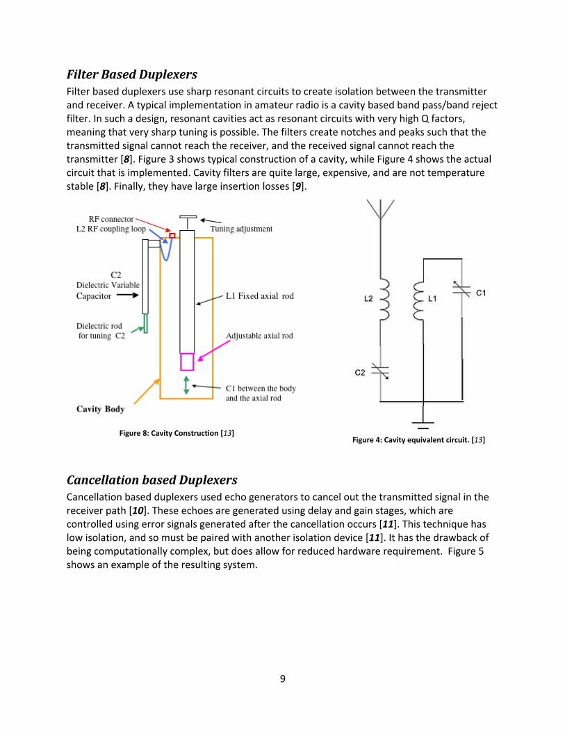
Filter Based Duplexers Filter based duplexers use sharp resonant circuits to create isolation between the transmitter and receiver. A typical implementation in amateur radio is a cavity based band pass/band reject filter. In such a design, resonant cavities act as resonant circuits with very high Q factors, meaning that very sharp tuning is possible. The filters create notches and peaks such that the transmitted signal cannot reach the receiver, and the received signal cannot reach the transmitter [8]. Figure 3 shows typical construction of a cavity, while Figure 4 shows the actual circuit that is implemented. Cavity filters are quite large, expensive, and are not temperature stable [8]. Finally, they have large insertion losses [9].
Cancellation based Duplexers Cancellation based duplexers used echo generators to cancel out the transmitted signal in the receiver path [10]. These echoes are generated using delay and gain stages, which are controlled using error signals generated after the cancellation occurs [11]. This technique has low isolation, and so must be paired with another isolation device [11]. It has the drawback of being computationally complex, but does allow for reduced hardware requirement. Figure 5 shows an example of the resulting system.
Figure 8: Cavity Construction [13]
Figure 4: Cavity equivalent circuit. [13]

10
Figure 5: Example Cancellation Duplexer. From [11]
Limitations in SDR Repeater Implementation Practical location, Antennas and Feed Lines: Antennas and feed lines are both required in implementing a repeater, however, in the context of our project this will not be considered. This equipment will vary based on frequencies defined by the end user. The end user also influences location. Although an antenna is not inherently required in the scope of the project, one may be required for resting purposes. To circumvent this, of course, this SDR radio must be extremely interoperable. ADC Power Consumption and Cost: As previously stated, much of the equipment will vary based on frequencies defined by the end user, and because of this the repeater must be very interoperable and customizable. This means that there is a very large range of RF signals it should be prepared to receive, and some RF signals operate at well into the gigahertz range. The ideal software radio requires the placement of the data converter next to the antenna, and the data converter samples the TF signal and the down-conversion process is completed in the digital domain. This puts extreme requirements on the ADC:
• A high sampling rate to support wide signal bandwidths • A large number of effective quantization bits to support a high dynamic range • An operating bandwidth of several GHz to allow the conversion of a signal over a • Greatly varying (and theoretically arbitrary) range of frequencies • Exhibit a large spurious free dynamic range to allow for the recovery of small scale • Signals in the presence of strong interferers while producing very little distortion • Minimal power consumption and cost
Ideally satisfying these goals exceeds the capability of currently available technology, therefore priorities must be set and tradeoffs between bandwidth, dynamic range, power consumption,

11
and cost must be made to find an acceptable solution for the data converter and repeater architecture [12].
Figure 9: Dynamic Range, Bandwidth, Power, and Cost ADC tradeoffs [12]
Overall, ADC performance has been increasing at a rate of about 25% per year. Power consumption has also been increasing, but at a slower rate than sampling rates so that overall ADC efficiency has been improving. The major constraint caused by ADC technology might therefore be eliminated in the near future. Processor Choice, Power Consumption and Cost: Microprocessors (both GPP and DSPs) are central to the concept of SDRs and inherently SDR repeaters. The capabilities of these processors largely control the percentage of radio operations that can be performed in software. The choice of a processor is generally influenced by the following considerations:
• Maximizing computational capacity – Abstractly, each waveform an SDR supports requires a minimum number of operations to be completed per unit time. In general, the faster these computations are completed, the greater the number of waveforms the SDR can support. In practice, however, what constitutes a fundamental unit of computation varies significantly from processor to processor.
• Minimizing power consumption – In general, all SWAP (size-weight and power) considerations factor into the selection of every component in an SDR. However, with power consumption levels that can extend into the hundreds of Watts, processor power consumption is generally an important consideration in SDR design.
• Minimizing reconfiguration time – Software radio, and particularly cognitive radio applications, can be limited by systems that are slow to change operation. Prior to development of partially-reconfigurable FPGAs, this was a primary rationale for choosing DSPs (reconfiguration times on the order of ns) over FPGAs (reconfiguration times on the order of ms). However, as this study focuses on DSPs and GPPs, for which reconfiguration time is not a significant concern, this issue is not explored in depth.

12
• Software considerations – Ease of development, code-reuse, code portability, and code maintainability are all influenced by the choice of processing architecture. However, these issues are beyond the scope of this study and will generally not constitute a fundamental limit to SDR deployment [12].
Figure 10: SDR Power Consumption vs. Computational Capability [12]
Trade organizations, Experts, and Researchers A number of trade organizations and current researchers were found working on different SDR projects at present. Some SDR research is even being done at Stevens right now. Experts and Researchers at Stevens
- VP of Research Enterprise, Joe Mitola – inventor of cognitive radio and SDR expert - Prof. Rajarathnam Chandramouli – Dynamic spectrum access - Prof. Yingying Chen – Intruder detection and localization - Prof. Cristina Comaniciu – Cross-layer design; MAC protocols - Prof. Hongbin Li – Signal detection and estimation - Prof. Bruce McNair – SDR test bed; DSP algorithms - Prof. Koduvayur Subbalakshmi – Security in cognitive networks - Prof. Yu-Dong Yao – Interference modeling; MAC protocols
Amateur Radio and SDR Trade Organizations
- SDR forum - Multiple IEEE journals and conferences - American Radio Relay League (ARRL)

13
Section III: Constraints & Ethical Concerns Technical Constraints for this project include: compliance with FCC rules and regulations, standards compliance for every protocol stack that the prototype implements, keeping power consumption to a reasonable level for practical use, and bandwidth considerations. Economic Constraints for this project include: the very small research and development budget given to each group ($250), ensuring that the design is economically viable to manufacture, and the critical requirement that the design be cheaper to maintain/implement than comparable non-SDR repeaters. Environmental Constraints for this project include: controlling unwanted spectrum access (harmonics, noise suppression), and ensuring that none of the required manufacturing/design processes involved in production are environmentally damaging. Health and Safety Constraints for this project include: keeping design and manufacturing processes safe, design engineers (group members) safe from possible electromagnetic radiation health concerns, and once again, FCC regulation compliance (for legal safety) Manufacturability Constraints for this project include: using common and easily reproducible components and manufacturing processes, and keeping the physical layer design as modular and easily maintainable as possible. Sustainability Constraints for this project include: the hardware must be powerful enough to handle software algorithms needed for future (yet undeveloped even) protocol stacks, and making the software modular enough so as to make it easily upgradable and maintainable. Ethical Constraints for this project include: ensuring that it works- that customers get a well-performing SDR repeater for amateur radio use, that the design does not infringe upon existing patents, and limiting interference with other licensed spectrum users. Section IV: S.W.O.T. Analysis This section refers only to new SWOT analysis points discovered during the process of researching practical implementation. Please refer to previous reports for already-listed SWOT analyses. Strengths:
- Practical SDR implementation is software-centric. This means that in general, the development cost will be fast and cheap, as software architecture is generally easier to develop and less resource-intensive than software design.

14
- The hardware components required for practical implementation are readily available and on the market
- There are plenty of SDR researchers and knowledgeable people even here at Stevens when advisement is needed
Weaknesses:
- Development of heterogeneous DSP/FPGA baseband hardware as well as software tunable RF/IF hardware will probably run the project significantly over-budget
- A number of significant design trade-offs will need to be made for hardware design, which in conjunction with other constraints, lower the performance of the final product.
Opportunities:
- SDR and cognitive radio are currently very hot research topics, with a lot of research grants and private investment. Possible future (outside the scope of the current project definition) enhancements could integrate a cognitive radio engine into the baseband software.
Threats:
- Software-centric design will call for high power consumption, which is a significant constraint for any radio design
Section V: References
[1] Huseyin Arslan and Hasari Celebi, "Software Defined Radio Architectures for Cognitive Radios," in Cognitive Radio, Software Defined Radio, and Adaptive Wireless Systems.: Springer, 2007, ch. 4, pp. 109-144.
[2] Tom Wada. (2005) All Digital FM Receiver. [Online]. http://www.ie.u-ryukyu.ac.jp/~wada/design05/spec_e.html
[3] Mahababul Hansan, Md Khan, and Farzana Akhter, "Design and Implementation of a QPSK Demodulator," BRAC University, Bangladesh, 2010.
[4] Zeyu Long, "Analysis of Modulation Scheme using GNU radio," CSU, 2009. [5] Digitalmodulation.net. (2007) The FSK Transmitter.
[Online]. http://www.digitalmodulation.net/fsk3.html [6] Leo G Maloratsky, "Transceiver Duplexer Design Considerations," Microwave Journal,
October 2008. [7] Wikipedia. Circulator. [Online]. http://en.wikipedia.org/wiki/Circulator [8] Dave Metz. (1998) Duplexer, Theory and Tune-Up.
[Online]. http://www.seits.org/duplexer/duplexer.htm [9] Behzad Ravazi, RF Microelectronics. Upper Saddle River: Prentice , 1998.
[10] S Chen, MA Beach, and JP McGeehan, "Division-free Duplex for Wireless Application,"

15
Electronic Letters, vol. 34, p. 147, 1998. [11] S Kannagara and M Faulkner, "Analysis of Adaptive Wideband Duplexer with Double-Loop
Cancellation," Vehicular Technology, IEEE Transactions, vol. 56, no. 4, pp. 1971-1982, July 2007.
[12] Charles W. Bostian, Jeffrey H. Reed, J. Randall Nealy, Fang Ge, and James Neel. (2008, December) Wireless @ Virginia Tech. [Online]. www.wireless.vt.edu; www.crtwireless.com
[13] amateur-radio.com. What is a Cavity Filter? [Online]. http://www.amateur-radio-wiki.net/index.php?title=What_is_a_cavity_filter%3F