sdrams: can’t live without them, but can we live with … · sdrams: can’t live without them,...
TRANSCRIPT

SDRAMs: Can’t Live Without Them, But Can We Live With Them?
Ray Ladbury GSFC/OrbitalMunir Shoga BSS
Rocky Koga Aerospace Corp.
Presented by Ray Ladbury at SEE Symposium in Manhattan Beach, CA April 23, 2003 2
Single-Event Effects in SDRAMs can be a nightmare!!
• Single-Event Latchup(SEL)--potentially destructive--at best, results in loss of all data stored on chip.
• Single-Event Upset (SEU)--can occur at at rate of several per day and multi-bit upsets a few times per day per chip.
• Single-Event Functional Interrupt (SEFI)--results in loss of chip functionality; power cycle (causing loss of all data on the chip) is usually necessary for recovery.
• Stuck Bits--can cause temporary or permanent loss of functionality of a single-bit, impairing reliability and error detection performance.
• Some experimenters have seen error/failure rates vary more than 10x lot to lot.
Presented by Ray Ladbury at SEE Symposium in Manhattan Beach, CA April 23, 2003 3
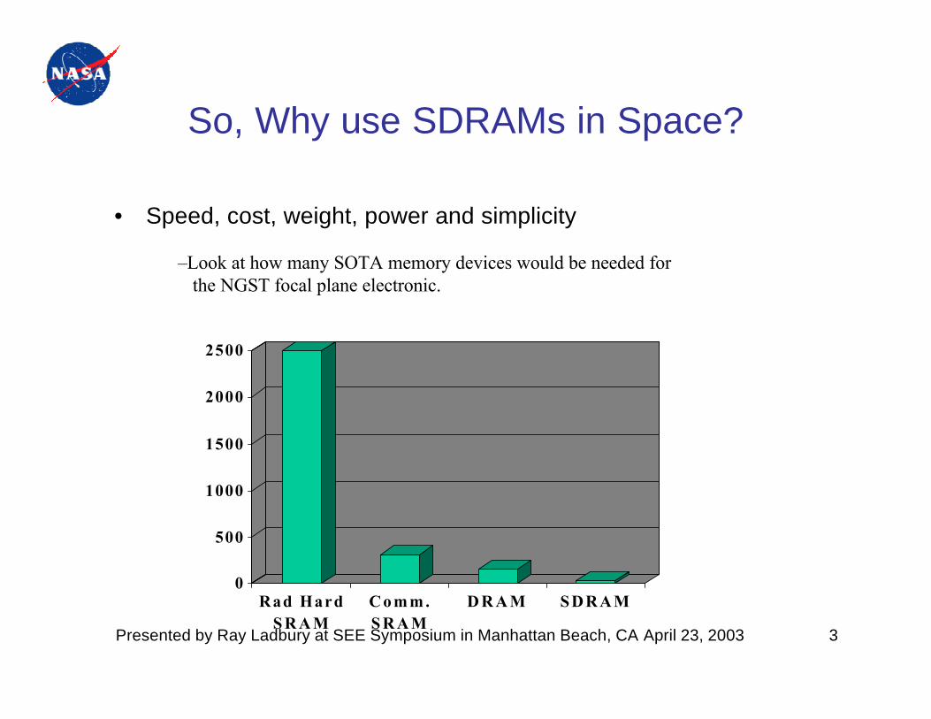
So, Why use SDRAMs in Space?
• Speed, cost, weight, power and simplicity
0
500
1000
1500
2000
2500
Rad HardS R A M
C o m m .S R A M
D R A M SDRAM
–Look at how many SOTA memory devices would be needed for the NGST focal plane electronic.

Presented by Ray Ladbury at SEE Symposium in Manhattan Beach, CA April 23, 2003 4
So the Question Becomes: How can weuse SDRAMS in Space?
•Use a multi-tiered defense against radiation-induced errors:–Testing to eliminate parts with hard failure modes and quantify other errors–Parts selection based on optimum (overall) performance–EDAC, memory scrubbing to minimize effects of SEUs, stuck bits and other errors
–System architecture to minimize effects of SEFIs, multibit errors, etc.
Would you storeyour data here?
SEEErrors
SEE Testing
PartsSelection
SystemMitigation
Robust SystemArchitecture
Presented by Ray Ladbury at SEE Symposium in Manhattan Beach, CA April 23, 2003 5
Outline of Approach
• Implications of Economics, Chip Process, Packaging and Architecture– The implications of a fiercely competitive commercial memory market– TID and SEE trends with small dimension CMOS– Testing difficulties posed by packaging– Chip Architecture and Error Modes
• Experience and Implications of Previous DRAM/SDRAM Tests– Test Results over several generations– Lot-to-Lot Variability for TID and SEE– Lessons Learned
• Designing Memory Systems to Accommodate Error Modes– Anticipating Error and Failure Modes– Tools: EDAC, System Design, Refresh, Scrubbing, Reset, Shielding– Performance Penalties for hardening

Presented by Ray Ladbury at SEE Symposium in Manhattan Beach, CA April 23, 2003 6
The Incredible Shrinking Pool of Suppliers• During the PC slump memory prices dropped 85%.
– Result is a large decrease in memory suppliers• Japanese exited business when Micron acquired Toshiba; still looking to expand• Hitachi spun off memory division--now Elpida
• It’s been feast or famine for >4 years—and mostly famine– Consolidation likely to continue.
• Economic pressures mean– Process is optimized for yield.
• Process changes frequently, and don’t expect to be notified.• Radiation performance is not even on the radar screen.• Same part may be fabricated at multiple foundries.
– Product cycle times are short.• In 2000, 64 Mbit SDRAMs predominated, now it’s 256 & 512 Mbit chips.
– 1 Gbit SDRAMs just now becoming available.
– History not an indicator of future performance.
• Very difficult to obtain vendor assistance
Presented by Ray Ladbury at SEE Symposium in Manhattan Beach, CA April 23, 2003 7
Process implications for Testing
• SDRAM chips implemented in high-speed, submicron CMOS– SEL is a definite risk
• Epi layers cost money and pose performance issues--most memories are fabricated on bulk silicon
– TID performance is acceptable for many missions (30-80 krads(Si))– Majority carrier device, so displacement damage not an issue– Small feature sizes mean
• Small node capacitances, so LET thresholds for SEE tend to be low • Limiting cross sections are small• single-event induced stuck bits a significant risk
– Feature sizes comparable to collection depths

Presented by Ray Ladbury at SEE Symposium in Manhattan Beach, CA April 23, 2003 8
Multi-bit Upsets can Dominate Error Rates
• Small feature sizes and multibit upsets– For small geometry cells, subset of ion paths that cause mult-bit
upsets is not negligible; can be ~10% of the single-bit rate for current generation.
– If physically adjacent bits belong to the same word, these multi-bit upset rates can dominate systems protected with single or double-bit EDAC
– Problem worsens as geometries shrink.

Presented by Ray Ladbury at SEE Symposium in Manhattan Beach, CA April 23, 2003 9
Packaging Issues• SDRAM packaging presents
significant issues for ion beam penetration.– Leads and metallic lead frames
obscure portions of the die.– Parts plastic encapsulated – plastic support structures, etc.
• Requires special considerations – Repackaging the device– de-encapsulation + peeling back
portions of lead frame– lapping chip underside and back-
irradiation (careful here!)• lapping too thin can change
charge-collection characteristics
– use ultra-high energy beams
Metal Lead frame

Presented by Ray Ladbury at SEE Symposium in Manhattan Beach, CA April 23, 2003 10
SDRAM Cells and Architectures
Simplified SDRAM Cell consists of a capacitor as the storage element and a FET that controls access to the storage element.
Timing Register
Sense A
mp
CLK CKE CS PAS CAS WE DQM
LDQM
CLK
ADD
LCB
R, LR
AS
Row Buffer Refresh Counter Row Decoder
Bank Select
Address R
egister
Col. B
uffer
16M x 4bits x 4B Memory Cells
Couumn Decoder
Latency & Burst Length
Programming Register
LWCBR
LCKELRAS, LWE LCAS
DQi
LWEI/O Control
Data Input Register Output B
uffer
Architecture of a 256-Mbit SDRAM
Presented by Ray Ladbury at SEE Symposium in Manhattan Beach, CA April 23, 2003 11
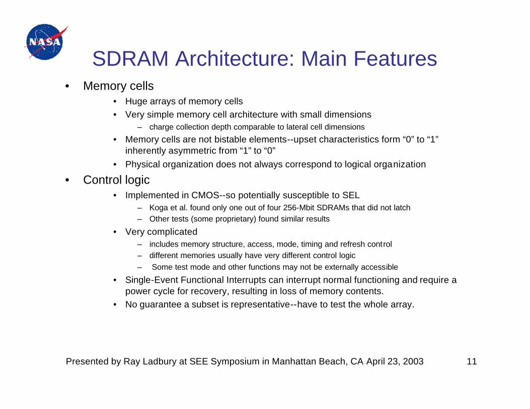
SDRAM Architecture: Main Features• Memory cells
• Huge arrays of memory cells• Very simple memory cell architecture with small dimensions
– charge collection depth comparable to lateral cell dimensions
• Memory cells are not bistable elements--upset characteristics form “0” to “1” inherently asymmetric from “1” to “0”
• Physical organization does not always correspond to logical organization
• Control logic• Implemented in CMOS--so potentially susceptible to SEL
– Koga et al. found only one out of four 256-Mbit SDRAMs that did not latch– Other tests (some proprietary) found similar results
• Very complicated– includes memory structure, access, mode, timing and refresh control– different memories usually have very different control logic– Some test mode and other functions may not be externally accessible
• Single-Event Functional Interrupts can interrupt normal functioning and require a power cycle for recovery, resulting in loss of memory contents.
• No guarantee a subset is representative--have to test the whole array.

Presented by Ray Ladbury at SEE Symposium in Manhattan Beach, CA April 23, 2003 12
What can we learn from previous tests?• First the good news
– TID tolerance is still adequate for many missions ( often 30-80 krads(Si))• Lot-to-lot variations can be significant (2x is not uncommon)
– Majority carrier device so displacement damage not an issue.– SEU rates (per bit) are remaining fairly low (but you have a LOT of bits)
• Now the bad news– SEL is a significant issue for all generations
• may be getting worse with time, and results may depend on test method
– Multi-bit SEU rates can be up to 10% of the single-bit rate• this could get worse with shrinking geometries.
– SEFI rates are still high and expected to remain so.– Stuck bit rates are rising somewhat
• may still be manageable for robust systems
• More bad news– Some tests have shown substantial variation in SEE rates lot-to-lot.– Leave aside the question of how you even define a lot in some cases.

Presented by Ray Ladbury at SEE Symposium in Manhattan Beach, CA April 23, 2003 13
Lessons Learned—Test Preparation• Learn as much about the part(s) to be tested as possible
– Good luck getting help from the manufacturer; SEM, DPA may be helpful
• Part preparation– High-LET ions must penetrate to sensitive regions, but be careful that part
preparation (lapping, etc.) doesn’t change part response.
• LETs, fluences and sample sizes depend on the mission and application– Null result with 1E7 ions/cm2 not inconsistent at 95% CL with a cross section
of 3E-7 cm2 ? may need to test many parts.– Missions flying more parts need to test more parts to higher fluences, LETs
• SDRAM tests are inherently complicated– Tests need to be planned to characterize errors important to the application
• Need to characterize each error mode enough to understand system implication
– Angular information is critical; test boards need to allow grazing incidence– Need to test the whole memory, with multiple modes and test patterns– Test results are generally too difficult to analyze on the fly.
• Bring sufficient storage media to store all the data. Plan multiple trips???
Presented by Ray Ladbury at SEE Symposium in Manhattan Beach, CA April 23, 2003 14
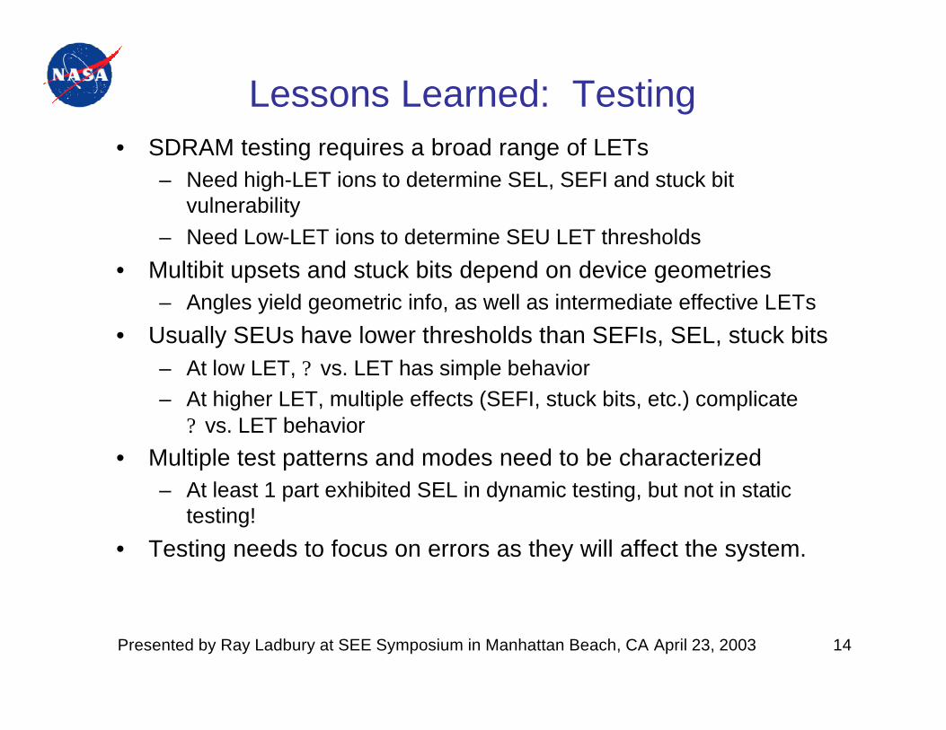
Lessons Learned: Testing• SDRAM testing requires a broad range of LETs
– Need high-LET ions to determine SEL, SEFI and stuck bit vulnerability
– Need Low-LET ions to determine SEU LET thresholds
• Multibit upsets and stuck bits depend on device geometries– Angles yield geometric info, as well as intermediate effective LETs
• Usually SEUs have lower thresholds than SEFIs, SEL, stuck bits– At low LET, ? vs. LET has simple behavior– At higher LET, multiple effects (SEFI, stuck bits, etc.) complicate
? vs. LET behavior
• Multiple test patterns and modes need to be characterized – At least 1 part exhibited SEL in dynamic testing, but not in static
testing!
• Testing needs to focus on errors as they will affect the system.
Presented by Ray Ladbury at SEE Symposium in Manhattan Beach, CA April 23, 2003 15
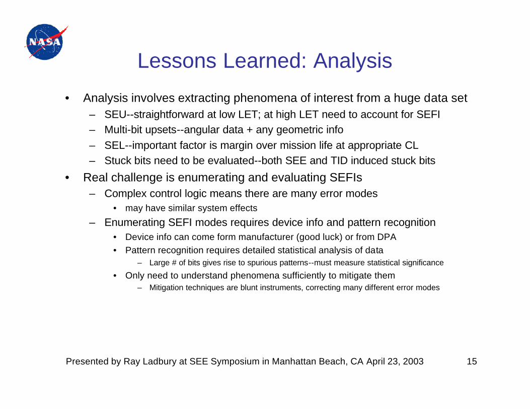
Lessons Learned: Analysis
• Analysis involves extracting phenomena of interest from a huge data set– SEU--straightforward at low LET; at high LET need to account for SEFI– Multi-bit upsets--angular data + any geometric info– SEL--important factor is margin over mission life at appropriate CL– Stuck bits need to be evaluated--both SEE and TID induced stuck bits
• Real challenge is enumerating and evaluating SEFIs– Complex control logic means there are many error modes
• may have similar system effects
– Enumerating SEFI modes requires device info and pattern recognition• Device info can come form manufacturer (good luck) or from DPA• Pattern recognition requires detailed statistical analysis of data
– Large # of bits gives rise to spurious patterns--must measure statistical significance
• Only need to understand phenomena sufficiently to mitigate them– Mitigation techniques are blunt instruments, correcting many different error modes
Presented by Ray Ladbury at SEE Symposium in Manhattan Beach, CA April 23, 2003 16
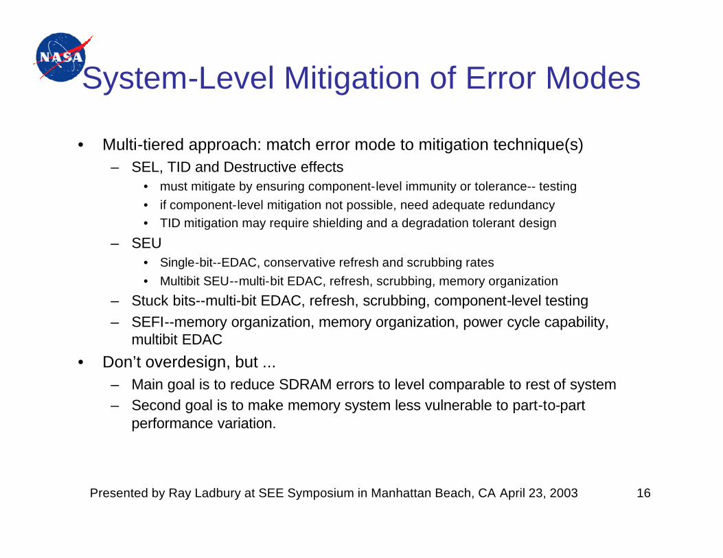
System-Level Mitigation of Error Modes
• Multi-tiered approach: match error mode to mitigation technique(s)– SEL, TID and Destructive effects
• must mitigate by ensuring component-level immunity or tolerance-- testing• if component-level mitigation not possible, need adequate redundancy• TID mitigation may require shielding and a degradation tolerant design
– SEU• Single-bit--EDAC, conservative refresh and scrubbing rates• Multibit SEU--multi-bit EDAC, refresh, scrubbing, memory organization
– Stuck bits--multi-bit EDAC, refresh, scrubbing, component-level testing– SEFI--memory organization, memory organization, power cycle capability,
multibit EDAC
• Don’t overdesign, but ...– Main goal is to reduce SDRAM errors to level comparable to rest of system– Second goal is to make memory system less vulnerable to part-to-part
performance variation.

Presented by Ray Ladbury at SEE Symposium in Manhattan Beach, CA April 23, 2003 17
Fault-Tolerant Design and Dominant Error Modes
• Dominant error modes depend on mitigation strategies employed.– Single-bit SEUs dominate if no mitigation or if refresh/scrub rates too
slow.– Multi-bit SEUs may dominate systems with EDAC.– SEFIs, block errors, etc. may dominate if memory architecture
organized so that EDAC handles multi-bit SEUs.– If the system is designed with EDAC, memory scrubbing and refresh
and fault-tolerant architecture, multiple errors (i.e. 2 SEFIs, SEFI+SEU…) may be required for the system to fail.
– Stuck bits can significantly decrease effectiveness of EDAC and other mitigation at EOL.
• Ensuring adequate performance at EOL may require multi-bit EDAC and faster refresh and scrubbing rates.
Presented by Ray Ladbury at SEE Symposium in Manhattan Beach, CA April 23, 2003 18
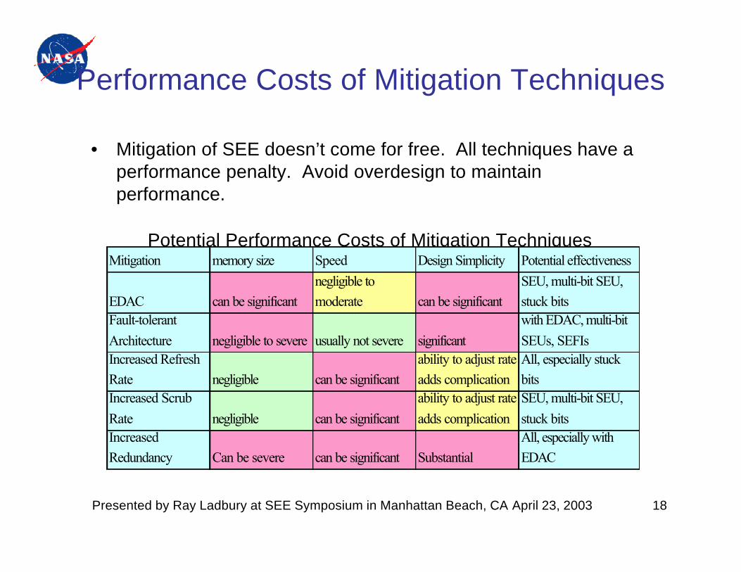
Performance Costs of Mitigation Techniques
• Mitigation of SEE doesn’t come for free. All techniques have a performance penalty. Avoid overdesign to maintain performance.
Potential Performance Costs of Mitigation TechniquesMitigation memory size Speed Design Simplicity Potential effectiveness
EDAC can be significantnegligible to moderate can be significant
SEU, multi-bit SEU, stuck bits
Fault-tolerant Architecture negligible to severe usually not severe significant
with EDAC, multi-bit SEUs, SEFIs
Increased Refresh Rate negligible can be significant
ability to adjust rate adds complication
All, especially stuck bits
Increased Scrub Rate negligible can be significant
ability to adjust rate adds complication
SEU, multi-bit SEU, stuck bits
Increased Redundancy Can be severe can be significant Substantial
All, especially with EDAC

Presented by Ray Ladbury at SEE Symposium in Manhattan Beach, CA April 23, 2003 19
Conclusions• Commercial SDRAMs can confer many significant advantages:
– Increased memory densities allow more memory, lower weight, lower power consumption and higher speeds.
– The pace of development in commercial memory devices is much more rapid than in the rad hard memory sector.
– TID performance is often adequate for many missions
• With these advantages comes considerable risk:– Use of commercial puts you at the mercy of the market place--good
luck! – SEE pose serious risks to system reliability and performance
• Destructive SEL is a common problem• SEFI and single- and multi-bit SEU can result in high error rates• Stuck bits can compromise system reliability and survivability
• Mitigating these risks requires a multi-tiered defense strategy