sec 08 electrical - body & chassis
DESCRIPTION
Sec 08 Electrical - Body & ChassisTRANSCRIPT

WORKSHOP MANUAL
TBR SERIES
ELECTRICAL-BODY AND CHASSIS
SECTION 8

NOTICE
Before using this Workshop Manual to assist you in performing vehicle
service and maintenance operations, it is recommended that you
carefully read and thoroughly understand the information contained in
Section - 0A under the headings “GENERAL REPAIR
INSTRUCTIONS” and “HOW TO USE THIS MANUAL”.
All material contained in this Manual is based on the latest product
information available at the time of publication.
All rights are reserved to make changes at any time without prior
notice.

ELECTRICAL-BODY AND CHASSIS 8-1
SECTION 8
ELECTRICAL-BODY AND CHASSIS
TABLE OF CONTENTS
PAGE
General Information ..........................................................................................................8 - 3
Notes for Working on Electrical Items .......................................................................8- 4
Symbols and Abbreviations ........................................................................................8- 10
Symbols ..................................................................................................................8- 10
Abbreviations .........................................................................................................8- 11
Parts for Electrical Circuit ...........................................................................................8- 12
Wiring ......................................................................................................................8- 12
Fuse .........................................................................................................................8 - 13
Fusible Link ............................................................................................................8- 13
Relay ........................................................................................................................8- 14
Diode .......................................................................................................................8- 15
Connector ...............................................................................................................8- 16
Battery .....................................................................................................................8- 17
Reading the Circuit Diagram .......................................................................................8- 20
Main Data and Specifications ..........................................................................................8- 22
Bulb Specifications ......................................................................................................8- 22
Relay and Fuse Box Location .....................................................................................8- 24
Relay Location (Relay and Fuse Box) ........................................................................8- 25
Fuse and Fusible Link Location (Relay and Fuse Box) ............................................8- 26
Fuse Location (Fuse Box) ...........................................................................................8- 27
Reference Table of Fuse, Fusible Link........................................................................8- 28
Grounding Point ...........................................................................................................8- 29
Reference Table .....................................................................................................8- 29
Location ..................................................................................................................8- 30
Main Cable Harness Routing ...........................................................................................8- 32
Fuse Block Circuit ........................................................................................................8- 34
System Repair ................................................................................................................. ..8- 35
Start and Charging .......................................................................................................8- 35

8-2 ELECTRICAL-BODY AND CHASSIS
PAGE
Lighting ...................................................................................................................... ...8- 39
Hazard Warning Flasher, Turn Signal Light, Back Up Light,
Horn and Stop Light .....................................................................................................8- 55
Windshield Wiper and Washer ....................................................................................8- 73
Meter, Warning Light and Indicator Light ..................................................................8- 93
Air Conditioning ...........................................................................................................8- 1 35
Power Door Lock .........................................................................................................8- 138
Power Window .............................................................................................................8- 147
Audio, Clock and Cigarette Lighter ............................................................................8- 161
Power Door Mirror ........................................................................................................8- 170
Transmission Control Module (A/T) ............................................................................8- 180
Connector List ................................................................................................................ ..8- 184

ELECTRICAL-BODY AND CHASSIS 8-3
GENERAL INFORMATION
The body and chassis electrical system operates on a twelve volt power supply with negative ground polarity.The main harness consists of the engine harness, the instrument harness, the body harness, and the chassisharness.The harnesses use a split corrugated tube to protect the wires from the elements.Wire size is determined by current flow, circuit length, and voltage drop.All wires have color-coded insulation.Wire color-codes are shown in the circuit diagrams.This makes it easier to trace circuits and to make the proper connections.
Each circuit consists of the following:
1. Power source - The battery and the alternator2. Wires - To carry electrical current through the circuit3. Fuses - To protect the circuit against current overload4. Relays - To protect voltage drop between the battery and the circuit parts and to protect the switch points against
burning5. Switches - To open and close the circuit6. Load - Any device, such as a light or motor, which converts the electrical current into useful work7. Ground - To allow the current to flow back to the power source

8-4 ELECTRICAL-BODY AND CHASSIS
NOTES FOR WORKING ON ELECTRICAL ITEMS
Ground cable Positive cable BATTERY CABLEDisconnecting the Battery Cable1. All switches should be "OFF" position.2. Disconnect the battery ground cable.3. Disconnect the battery positive cable.CAUTION:It is important that the battery ground cable bedisconnected first.Disconnecting the battery positive cable first can result ina short circuit.
Connecting the Battery CableFollow the disconnecting procedure in the reverse order toconnect the battery cables.CAUTION:Clean the battery terminal and apply light coat of grease toprevent terminal corrosion.
CONNECTOR HANDLINGDisconnecting the ConnectorsSome connectors have a tang lock to hold the connectorstogether during vehicle operation.Some tang locks are released by pulling them towards you 1 .Other tang locks are released by pressing them forward 2 .Determine which type of tang lock is on the connector beinghandled.
Firmly grasp both sides (male and female) of the connector.Release the tang lock and carefully pull the two halves of theconnector apart.Never pull on the wires to separate the connectors.This will result in wire breakage.
ELECTRICAL-BODY AND CHASSIS 8-5
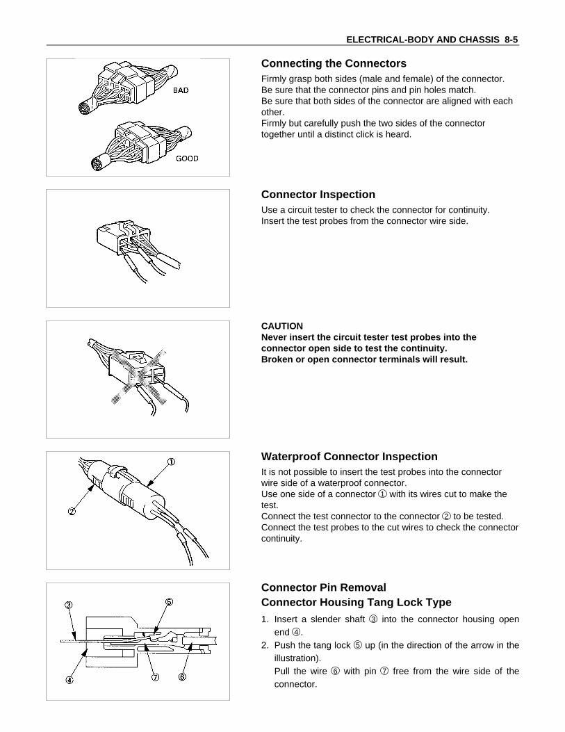
Connecting the ConnectorsFirmly grasp both sides (male and female) of the connector.Be sure that the connector pins and pin holes match.Be sure that both sides of the connector are aligned with eachother.Firmly but carefully push the two sides of the connectortogether until a distinct click is heard.
Connector InspectionUse a circuit tester to check the connector for continuity.Insert the test probes from the connector wire side.
CAUTIONNever insert the circuit tester test probes into theconnector open side to test the continuity.Broken or open connector terminals will result.
Waterproof Connector InspectionIt is not possible to insert the test probes into the connectorwire side of a waterproof connector.Use one side of a connector 1 with its wires cut to make thetest.Connect the test connector to the connector 2 to be tested.Connect the test probes to the cut wires to check the connectorcontinuity.
Connector Pin RemovalConnector Housing Tang Lock Type1. Insert a slender shaft 3 into the connector housing open
end 4 .2. Push the tang lock 5 up (in the direction of the arrow in the
illustration).Pull the wire 6 with pin 7 free from the wire side of theconnector.

8-6 ELECTRICAL-BODY AND CHASSIS
Pin Tang Lock Type1. Insert a slender shaft 3 into the connector housing open
end 4 .2. Push the tang lock 8 flat (toward the wire side of the
connector).Pull the wire 6 with pin 7 free from the wire side of theconnector.
Connector Pin Insertion1. Check that the tang lock 8 is fully up.2. Insert the pin 7 from the connector wire side 9 .
Push the pin in until the tang lock closes firmly.3. Gently pull on the wires 6 to make sure that connector pin
is firmly set in place.
Fuse ReplacementThe replacement fuse must have the same amperagespecification as the original fuse.Never replace a burn out fuse with a fuse of a differentamperage specification.Doing so can result in an electrical fire or other serious circuitdamage.
Parts HandlingBe careful for parts handling and any part should not bedropped or thrown, otherwise short circuit or disorder mayresult.
Wiring Harness1. When assembling the parts, be careful not to bite or wedge
the wiring harness.2. All electrical connections must be kept be kept clean and
tight.

ELECTRICAL-BODY AND CHASSIS 8-7
3. Use a grommet or guard tube to protect the wiring harnessfrom contacting a sharp edge or surface.
4. Position the wiring harness with enough clearance from theother parts and guard the wiring harness with a vinyl tube toavoid direct contact.
5. The wiring harness between engine and chassis should belong enough to prevent chafing or damage due to variousvibrations.

8-8 ELECTRICAL-BODY AND CHASSIS
SPLICING WIREOpen the HarnessIf the harness is taped, remove the tape.To avoid wire insulation damage, use a sewing "seam ripper"(available from sewing supply stores) to cut open the harness.If the harness has a black plastic conduit, simply pull out thedesired wire.
Cut the wireBegin by cutting as little wire off the harness as possible.You may need the extra length of wire later if you decide to cutmore wire off to change the location of a splice.You may have to adjust splice locations to make certain thateach splice is at least 1-1/2" (40 mm) away from other splices,harness branches, or connectors.
Strip the insulationWhen replacing a wire, use a wire of the same size as theoriginal wire.Check the stripped wire for nicks or cut stands.If the wire is damaged, repeat the procedure on a new sectionof wire.The two stripped wire ends should be equal in length.
Crimp the WiresSelect the proper clip to secure the splice.To determine the proper clip size for the wire being spliced,follow the directions included with your clips.Select the correct anvil on the crimper.(On most crimpers your choice is limited to either a small orlarge anvil.)Overlap the two stripped wire ends and hold them betweenyour thumb and forefinger.Then, enter the splice clip under the stripped wires and hold itin place.
• Open the crimping tool to its full width and rest one handleon a firm flat surface.
• Center the back of the splice clip on the proper anvil andclose the crimping tool to the point where the back of thesplice clip touches the wings of the clip.
• Make sure that the clip and wires are still in the correctposition. Then, apply pressure until the crimping tool closes.
Before crimping the ends of the clip, be sure that:• The wires extend beyond the clip in each direction.• No strands of wire are cut loose.• No insulation is caught under the clip.Crimp the splice again, once on each end.Do not let the crimping tool extend beyond the edge of the clipor you may damage or nick the wires.

ELECTRICAL-BODY AND CHASSIS 8-9
SolderApply 60/40 rosin core solder to the opening in the back of theclip.Follow the manufacturer's instructions for the solder equipmentyou are using.
Tape the SpliceCenter and roll the splicing tape.The tape should cover the entire splice.Roll on enough tape to duplicate the thickness of the insulationon the existing wires.Do not flag the tape.Flagged tape may not provide enough insulation, and theflagged ends will tangle with the other wires in the harness.
If the wire does not belong in a conduit or other harnesscovering, tape the wire again.Use a winding motion to cover the first piece of tape.

8-10 ELECTRICAL-BODY AND CHASSIS
SYMBOLS AND ABBREVIATIONS
SYMBOLS
Symbol Meaning of Symbol Symbol Meaning of Symbol
Fuse Bulb
Fusible link Double filament bulb
Fusible link wire Motor
Switch Variable resistor Rheostat
SwitchCoil (inductor),solenoid,magnetic valve
Switch (Normal close type)
Contact wiring Relay
Battery
Diode Connector
Electronic Parts Light emitting diode
Resistor Reed switch
Speaker Condenser
Buzzer Horn
Circuit breaker Vacuum switching valve
ELECTRICAL-BODY AND CHASSIS 8-11
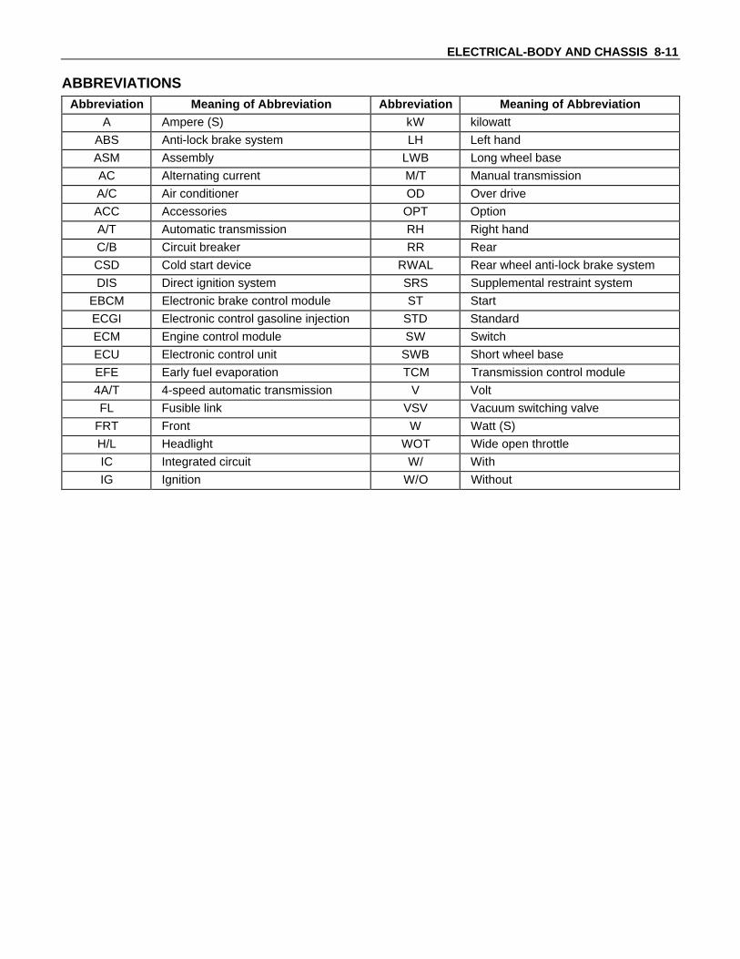
ABBREVIATIONSAbbreviation Meaning of Abbreviation Abbreviation Meaning of Abbreviation
A Ampere (S) kW kilowatt
ABS Anti-lock brake system LH Left hand
ASM Assembly LWB Long wheel base
AC Alternating current M/T Manual transmission
A/C Air conditioner OD Over drive
ACC Accessories OPT Option
A/T Automatic transmission RH Right hand
C/B Circuit breaker RR Rear
CSD Cold start device RWAL Rear wheel anti-lock brake system
DIS Direct ignition system SRS Supplemental restraint system
EBCM Electronic brake control module ST Start
ECGI Electronic control gasoline injection STD Standard
ECM Engine control module SW Switch
ECU Electronic control unit SWB Short wheel base
EFE Early fuel evaporation TCM Transmission control module
4A/T 4-speed automatic transmission V Volt
FL Fusible link VSV Vacuum switching valve
FRT Front W Watt (S)
H/L Headlight WOT Wide open throttle
IC Integrated circuit W/ With
IG Ignition W/O Without

8-12 ELECTRICAL-BODY AND CHASSIS
PARTS FOR ELECTRICAL CIRCUIT
WIRINGWire ColorAll wires have color-coded insulation.Wires belonging to system's main harness will have a singlecolor.Wires belonging to a system's sub-circuits will have a coloredstripe.Striped wires use the following code to show wire size andcolors.Example: 0.5 G / R
Red (Stripe color)Green (Base color)Wire size (0.5mm2)
Abbreviations are used to indicate wire color within a circuitdiagram.Refer to the following table.
Wire Color-Coding
Color-Coding Meaning Color-Coding Meaning
B Black BR Brown
W White LG Light green
R Red GR Grey
G Green P Pink
Y Yellow LB Light blue
L Blue V Violet
O Orange
Distinction of Circuit by Wire Base Color
Base color Circuits Base color Circuits
B Starter circuit and grounding circuit Y Instrument circuit
W Charging circuit L, O, BR,
R Lighting circuit LG, GR, Other circuits
G Signal circuit P, LB, V
Wire SizeWire size is specified with the metric gauge system.The metric gauge system gives the wire size in cross sectionalarea measured in square millimeters.

ELECTRICAL-BODY AND CHASSIS 8-13
Wire Size Specifications
Normal sizeCross sectional area
(mm2)
Outside diameter
(mm)
Allowable current
(A)
0.3 0.372 1.8 9
0.5 0.563 2.0 12
0.85 0.885 2.2 16
1.25 1.287 2.5 21
2 2.091 2.9 28
3 3.296 3.6 37.5
5 5.227 4.4 53
8 7.952 5.5 67
15 13.36 7.0 75
20 20.61 8.2 97
Normal Blown FUSEFuses are the most common form of circuit protection used invehicle wiring.A fuse is a thin piece of wire or strip of metal encased in aglass or plastic housing.It is wired in series with the circuit it protects.When there is an overload of current in a circuit, such as ashort of a ground, the wire or metal strip is designed to burnout and interrupt the flow of current.This prevents a surge of high current from reaching anddamaging other components in the circuit.Determine the cause of the overloaded before replacing thefuse.Never replace a blown fuse with a fuse of a different amperagespecification.Doing so can result in an electrical fire or other serious circuitdamage.A blown fuse is easily identified.
Normal Blown FUSIBLE LINKThe fusible link is primarily used to protect circuits where highamounts of current flow and where is would not be practical touse a fuse.For example, the starter circuit.When a current overload occurs, the fusible link melts openand interrupts the flow of current so as to prevent the rest ofthe wiring harness from burning.Determine the cause of the overload before replacing thefusible link.The replacement fusible link must have the same amperagespecification as the original fusible link.Never replace a blown fusible link with fusible link of a differentamperage specification.Doing so can result in an electrical fire or other serious circuitdamage.A blown fusible link is easily identified.

8-14 ELECTRICAL-BODY AND CHASSIS
Fusible Link Specifications
Type Rating Case Color Maximum Circuit Current(A)
Connector 30A Pink 15
Connector 40A Green 20
Bolted 50A Red 25
Bolted 60A Yellow 30
Bolted 80A Black 40
RELAYBattery and load location may require that a switch be placedsome distance from either component.This means a longer wire and a higher voltage drop 1 . Theinstallation of a relay between the battery and the load reducesthe voltage drop 2 .Because the switch controls the relay, amperage through theswitch can be reduced.
Relay Specifications and Configurations
Name/Color
Ratedvoltage/ Coilresistance
Internal circuit
1T(MR5C)/Black
12VApprox. 90ΩMinimumoperatingvoltage:7V at25°C (77°F)
1T(MR5C)/Brown
12VApprox. 90ΩMinimumoperatingvoltage: 10.5Vat 25°C (77°F)
* Relay contact shown in the wiring diagram indicates condition before actuation.
ELECTRICAL-BODY AND CHASSIS 8-15
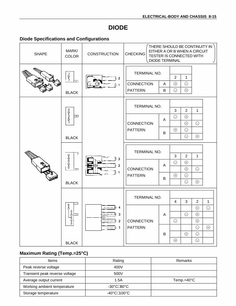
DIODE
Diode Specifications and Configurations
SHAPEMARK/COLOR
CONSTRUCTION CHECKING
THERE SHOULD BE CONTINUITY INEITHER A OR B WHEN A CIRCUITTESTER IS CONNECTED WITHDIODE TERMINAL
BLACK
2 1
CONNECTION A + -
PATTERN B - +
TERMINAL NO.
BLACK
3 2 1
- +
CONNECTION + -
PATTERN + -
- +B
A
TERMINAL NO.
BLACK
3 2 1
- +
CONNECTION + -
PATTERN + -
- +B
A
TERMINAL NO.
BLACK
4 3 2 1
+ -
A - +
CONNECTION - +
PATTERN - +
B + -
+ -
TERMINAL NO.
Maximum Rating (Temp.=25 °C)
Items Rating Remarks
Peak reverse voltage 400V
Transient peak reverse voltage 500V
Average output current 1.5A Temp.=40°C
Working ambient temperature -30°C∼80°C
Storage temperature -40°C∼100°C

8-16 ELECTRICAL-BODY AND CHASSIS
CONNECTORThe connector pin shape determines whether the connector ismale or female.The connector housing configuration does not determinewhether a connector is male or female.
The symbol illustrated in the figure is used as connector in thecircuit this section.
Connector is identified with a number.
The applicable terminal number is shown for each connector.
Connector terminal numbers are clearly shown.Male side connector terminal numbers are in sequence fromupper right to lower left.Female side connector terminal numbers are in sequence fromupper left to lower right.NOTE:For those connectors on which specific terminal numberson symbols are shown, the terminal numbers or symbolsare used in the circuit diagram, irrespective of the aboverule.

ELECTRICAL-BODY AND CHASSIS 8-17
BATTERYInspection1. Check the battery terminals 1 for corrosion.2. Check the battery cables 2 for looseness.3. Check the battery case 3 for cracks and other damage.4. Check the battery electrolyte level.
If the electrolyte level is excessively low, the battery must bereplaced.
5. If the battery has a built-in hydrometer, perform thefollowing steps.1) Carefully clean the battery upper surface.2) Check the hydrometer.
The hydrometer design will vary with the batterymanufacturer.Refer to the illustration shown on the battery.
Battery Replacement1. Disconnect the battery ground cable 1 .2. Disconnect the battery positive cable 2 .3. Remove the battery clamp 3 .4. Remove the batteryCaution:It is important that the battery ground cable be removedfirst.Removing the battery positive cable first can result in ashort circuit.
Jump Starting the Engine with a Booster BatteryThe following description assumes that you are using a boosterbattery mounted on a second vehicle.The listed steps (with some minor modifications) are alsoapplicable if you are using a naked booster battery or specialbattery charging equipment.

8-18 ELECTRICAL-BODY AND CHASSIS
Caution:Never push or tow the vehicle in an attempt to start it.Extensive damage to the emission system and othervehicle parts will result.(only catalytic converter vehicle)Treat both the discharged battery and the booster batterywith great care when using jumper cables.Carefully follow the procedure outlined below.Always be aware of the dangers of sparking.Failure to follow the following procedure can result in:a. Serious personal injury, specially to your eyes.b. Extensive property damage from a battery explosion,
battery acid discharge, or electrical file.c. Extensive damage to the electronic components of
both vehicles.Do not use a 24 volt booster battery.Serious damage to the vehicle's electrical system andelectronic components will result.
Jump Starting Procedure1. Set the parking brake on both vehicles.2. If one or both vehicles is equipped with a manual
transmission, place the gear shift in the "NEUTRAL"position.
3. Turn off the ignition on both vehicles.4. Turn off all vehicle lights and accessories.5. Check the built-in hydrometer on the discharged Battery (If
so equipped).If there is no hydrometer indication abandon the jump startprocedure.
6. Be sure that the two vehicles are not touching.Attach the end of one jumper cable to the booster batterypositive terminal.
7. Attach the other end of the same cable to the dischargedbattery positive terminal.
8. Once again, check that the booster battery has a 12 voltrating.
9. Attach one end of the remaining booster cable to thebooster battery negative terminal.
10.Attach the other end of the booster cable to a solid ground(such as the air conditioner compressor mounting bracketor the alternator mounting bracket) in the engine room ofthe vehicle with the discharged battery.Be sure that the ground connection is at least 500 mm (20in) from the discharged battery.

ELECTRICAL-BODY AND CHASSIS 8-19
Caution:Do not attach the booster cable to the discharged batterynegative terminal.
11.Start the engine of the vehicle with the booster battery.Check that all unnecessary electrical accessories are off.
12.Start the engine of the vehicle with the discharged battery.13.Remove the jumper cables in the reverse order to which
they were attached.
Caution:Be absolutely sure to remove the negative jumper cablefrom the vehicle with the discharged battery first.

8-20 ELECTRICAL-BODY AND CHASSIS
READING THE CIRCUIT DIAGRAM
In this manual, each system has its own parts location illustration and circuit diagram.And connector configurations used in the circuit diagram are shown at the end of this manual.PARTS LOCATION: The parts location shows the location of the connectors 1 and the harnesses 2 used in theeach system.CIRCUIT DIAGRAM: The circuit diagram shows the power supply 3 , the load or loads 4 and the groundingpoint(s) 5 .CONNECTOR LIST: The connector configuration shows each connector's number 6 , configuration 7 and the pinnumbers 8 .
PARTS LOCATION
ER-11
RELAY&FUSE BOX(X-2,X-7)
P-7
P-8
P-2
ER-7
TE-4 TE-7 P-5
P-4P-9 ER-9
H-5,6H-4*
H-2
H-3
ER-16
I-3
*=M/T
P-1P-6
1
2

ELECTRICAL-BODY AND CHASSIS 8-21
CIRCUIT DIAGRAM
P-8
P-6BATTP-1
P-9 P-7
P-7 : EARTH ; BODYP-8 : EARTH ; FRAMEP-9 : EARTH ; ENGINE
30B
/Y
9B/Y
3W/B
3B/Y 0.5Y O/D RELAY etc.
WIPER
3B/W
0.5W/G(M/T)
0.5W/R(A/T)
0.5W/G(A/T)
5B/Y
MAINEB-360A
8B/R
IGNEB-240A
ALT
B
ACC
IG
ST
ER-161
METERC-110A
ENGINEC-215A
FRT WIPERC-320A
ER-163
ER-165
SW ; STARTER
X-74
ER-91
X-72
X-73
X-71
ER-71
H-44
X-21
X-25
X-75
RELAY ;CHARGE
0.5W/L
3W
3W5W
30B
/R
3B/W 3B/W
5W
0.85
B/Y
0.5Y
0.85
W/R
0.5B
0.85B/Y
0.5B
0.5B
S IG.
LBACG
RELAY ;STARTER
STARTER
X-24
X-22
H-22
H-67
H-35
TE-42
P-5 P-2
FUEL CUT
ER-11EARTH ; E/R (RH) 0.85B 0.85B
P-4
STARTERE-110A
TE-7
(M/T)
H-51(A/T)
0.85B/Y
0.85B/Y
0.85B/Y
1.25LG/W
0.85B/Y
H-3
14
I-3
10
ER-7
2
ER-7
3
ME
TE
R
CH
G.
I-3
5
TE-43
H-66
H-21
SW ; INHIBITOR(A/T)
M
3
4
5
CONNECTOR LIST

8-22 ELECTRICAL-BODY AND CHASSIS
MAIN DATA AND SPECIFICATIONS
BULB SPECIFICATIONS
HEAD LIGHT
FRONT ROOM LIGHT
FRONT COMBINATION LIGHT
BACK UP LIGHT
TAIL & STOP LIGHT
LICENSE PLATE LIGHT
REAR ROOM LIGHT
REAR TURN SIGNAL LIGHT
Light Name Bulb No.Rated Power
V-WNumberof Bulbs
LensColor
Remarks
H4 12-60/55 2 White Halogen
R2 12-45/40 2 White
Front turn signal light - 12-21 2 White
Rear turn signal light P21W 12-21 2 Amber
Tail and stop light P21/5W 12-21/5 2 Red
Back up light P21W 12-21 2 White
License plate light W5W 12-5 1 or 2 White
Clearance light W5W 12-5 2 White
A/C-Heater control light - 12-0.7 1 -
Dome light (FRT) - 12-10 1 White
Dome light (RR) - 12-10 1 White
Inspection light - 12-5 1 White
Headlight
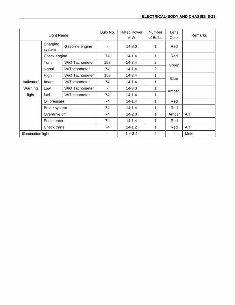
ELECTRICAL-BODY AND CHASSIS 8-23
Light NameBulb No. Rated Power
V-WNumberof Bulbs
LensColor
Remarks
Chargingsystem
Gasoline engine - 14-3.0 1 Red
Check engine 74 14-1.4 1 Red
Turn W/O Tachometer 158 14-3.4 2
signal W/Tachometer 74 14-1.4 2
High W/O Tachometer 158 14-3.4 1
Indicator/ beam W/Tachometer 74 14-1.4 1
Warning Low W/O Tachometer - 14-3.0 1
light fuel W/Tachometer 74 14-1.4 1
Oil pressure 74 14-1.4 1 Red
Brake system 74 14-1.4 1 Red
Overdrive off 74 14-2.0 1 Amber A/T
Sedimenter 74 14-1.4 1 Red
Check trans 74 14-1.2 1 Red A/T
Illumination light - 1.4-3.4 4 - Meter
Green
Blue
Amber

8-24 ELECTRICAL-BODY AND CHASSIS
RELAY AND FUSE BOX LOCATION
RELAY & FUSE BOX FUSE BOX

ELECTRICAL-BODY AND CHASSIS 8-25
RELAY LOCATION (RELAY AND FUSE BOX)
RELAY & FUSE BOX
X-1X-3
X-4
X-5
X-6
X-7
X-8
X-9
X-10
X-11
X-2
X-13
X-12
RELAYEngine model
NO.4JA1-NA, 4JA1-L
X-1 RELAY; HVAC
X-2 RELAY; STARTER
X-3 RELAY; (A/C COMP)
X-4 RELAY; (POWER WINDOW)
X-5 RELAY; TAIL LIGHT
X-6 RELAY; (SHIFT LOCK)
X-7 -
X-8 RELAY; FOG LIGHT
X-9 RELAY; (A/C CUT)
X-10 RELAY; DIMMER
X-11 RELAY; HEAD LIGHT
X-12 RELAY; CHARGE
X-13 -

8-26 ELECTRICAL-BODY AND CHASSIS
FUSE AND FUSIBLE LINK LOCATION (RELAY AND FUSE BOX)
RELAY & FUSE BOX
E-8E-1E-9E-2
E-10E-3E-11E-4E-12E-5E-13E-6E-14E-7
EB-2
EB-3
EB-5
FUSE FUSIBLE LINKFuse No. Capacity Indication on lable Fuse No. Capacity Indication on lable
E-1 10A STARTER EB-2 40A IGN:B1
E-2 10A H/LIGHT LH EB-3 60A MAIN
E-3 10A H/LIGHT RH EB-5 30A (POWER WINDOW)
E-4 15A HORN HAZARD
E-5 15A (FOG LIGHT)
E-6 - -
E-7 - -
E-8 15A D/LOCK
E-9 15A AUDIO (B) DOME L.
E-10 10A STOP LIGHT
E-11 10A TAIL LIGHT
E-12 10A A/C
E-13 20A BLOWER
E-14 20A (RR. COOLER)

ELECTRICAL-BODY AND CHASSIS 8-27
FUSE LOCATION (FUSE BOX)
C-1 C-4
C-2 C-5
C-3 C-6
FUSENo. Capacity Indication on label No. Capacity Indication on label
C-1 10A METER C-4 10A RR. WIPER
C-2 15A ENGINE C-5 15A TURN, BACK
C-3 20A FT. WIPER C-6 15A AUDIO (ACC), CIGAR
FUSE BOX

8-28 ELECTRICAL-BODY AND CHASSIS
REFERENCE TABLE OF FUSE, FUSIBLE LINKFUSE(Relay and fuse box)
Fuse No. Capacity Indication on lable Parts (Load)E-1 10A STARTER Ignition SW, Starter relay
E-2 10A H/LIGHT LHHeadlight LH, High beam indicator light,Dimmer-passing SW
E-3 10A H/LIGHT RHHeadlight RH, High beam indicator light,Dimmer-passing SW
E-4 15A HORN HAZARD Hazard SW, Flasher unit, Horn relay, Horn SW, Horn
E-5 15A FOG LIGHT Fog light
E-6 - - -
E-7 - - -
E-8 15A D/LOCKDoor lock SW-driver side, Door lock SW-driver side,Door lock actuator
E-9 15A AUDIO (B) DOME L. Audio, Clock, Room light
E-10 10A STOP LIGHTStop light SW, Stop light, High mounted stop light,TCM (B)
E-11 10A TAIL LIGHTTail relay, Clearance light, Tail light, License plate light,Illumination lights, Lighting SW
E-12 10A A/CPressure SW, Electronic thermostat, Fan SW,Magnetic cluch, VSV; FICD, A/C relay
E-13 20A BLOWER Blower motor, A/C relay, Blower resistor
E-14 20A RR COOLER -
FUSE(Fuse Box)
Fuse No. Capacity Indication on lable Parts (Load)
C-1 10A METERVehicle speed sensor, Meter gauges,Indicator and Warning lights
C-2 15A ENGINEIgnition SW, Fuel cut solenoid, Thermo SW,AC Generator, Charge relay, TCM (IG)
C-3 20A FT. WIPERWindshield wiper & washer SW,Windshield wiper motor, Windshield washer motor,Windshield intermittent relay
C-4 10A RR. WIPER -
C-5 15A TURN, BACK
Power window relay,FRT power window & door lock SW-driver side,RR power window SW, Hazard SW, Flasher unit,Turn signal SW, Back up light SW, Back up light
C-6 15A AUDIO (ACC), CIGAR Audio, cigar lighter
FUSIBLE LINK(Relay and fuse box)
Fusible link No. Capacity Indication on label Remarks
EB-2 40A IGN-B1 -
EB-3 60A MAIN -
EB-5 30A (POWER WINDOW) Power window & door lock SW, Powerwindow motor, Power window relay

ELECTRICAL-BODY AND CHASSIS 8-29
GROUNDING POINTREFERENCE TABLE
Connector No. Cable harness Location Parts (Load)
I-13
Instrument panel
Body-RH(at driver’s feet)
FRT power window SW-driver side, Door lock SW,Door mirror control SW, Flasher unit, Illuminationlight (Meter, Hazard SW), Cigarette lighter, FogSW, Clock, RR wiper SW, RR washer SW
I-2Body-LH
(at passenger’sfeet)
FRT Fan SW, Door lock controller, Heater bezel,Illumination light (Bezel)
ER-11 Engine roomharness
Fender-RH(behind engine
coolantreservoir)
Vehicle speed sensor, Power window relay,FRT washer motor, Starter relay, Charge relay,Fog relay, Dimmer relay, A/C relay, A/C comp relay,Combination SW, Fog light-RH, Position light-RH,FRT turn signal light-RH, Meter interface
B-9 Body harnessFender-LH
(back of watersedimenter)
Windshield wiper motor (FRT, RR),RR windshield washer motor, RR fan SW,Shift lever SW, Fuel filter SW, OD/OFF SW,FRT turn signal light-LH, RR turn signal light (RH,LH),Back up light (RH, LH), Stop light (RH, LH),Hi-mount stop light, Position light-LH, Fog light-LH,License plate light, Tail light (RH, LH), A/C amplifier,Diagnosis connector, TCM
P-7 Body-RH(behind battery)
Battery (-)
P-8Battery harness
Frame(near powersteering gear
box)
Engine
P-9
Engine(at cooler
compressorbracket)
Battery (-), Frame

8-30 ELECTRICAL-BODY AND CHASSIS
LOCATION
P-8
B-9
ER-11
P-7

ELECTRICAL-BODY AND CHASSIS 8-31
P-9

8-32 ELECTRICAL-BODY AND CHASSIS
MAIN CABLE HARNESS ROUTING
P-7
P-8
P-6P-1
P-9
I-13
H-1H-2H-8
H-7
H-3H-15
I-2
ENGINE ROOMHARNESS
BODY HARNESS
BATTERY POSITIVE CABLE
BATTERY NEGATIVE CABLE
INSTRUMENT HARNESS
TRANSMISSION &ENGINE HARNESS
ER-11
H-9
H-14
H-5H-6H-4*
RELAY &FUSE BOX
FUSE BOX
*=M/T
B-9

ELECTRICAL-BODY AND CHASSIS 8-33
H-3H-15
CHASSIS HARNESS
DOME LIGHTHARNESS
REAR COOLERHARNESS
FRONT DOOR HARNESS-RH
REAR DOOR HARNESS-RH
BACK DOORHARNESS REAR DOOR
HARNESS-LH
FRONT DOORHARNESS-LH
P-7
P-8
P-6P-1
P-9
I-13
H-1H-2H-8
H-16H-7
I-2
H-13
ER-11
H-10
H-11H-12
H-9
H-14B-9
RELAY & FUSE BOX

8-34 ELECTRICAL-BODY AND CHASSIS
FUSE BLOCK CIRCUIT30
B/Y
9B/Y
3W/B
5B/Y
MAIN60A
8B/R
IGN40A
ACC
OFF
B
ST IG
E-11 TAIL10A
SW ; STARTER 1
2
5 3
RELAY ; TAIL
RELAY ; STARTER
RELAY ; FOG
RELAY ; A/C
0.5B
1.25W
3W
5W3W
1.25W
1.25W1.25G/R
0.5G/R0.85B/Y
0.85W/R
0.5W/L
0.5G/YE-5 FOG15A 0.85R/G
0.5Y/L
E-12 A/C10A
0.5BR
E-13 BLOWER20A 2L/W
E-14 RR COOLER20A 2L/R
E-8 DOOR LOCK15A 0.85B/L
E-10 STOP10A 0.5G/W
E-9 AUDIO(B) CLOCK ROOM15A 0.85R
C-1 METER10A 0.5Y
C-2 ENGINE15A
0.85B/Y 0.85B/Y
C-3 FT WIPER20A 1.25LG/W
C-4 RR WIPER10A 0.5W/L
C-5 TURN,BACK15A 0.85R/B
E-1 STARTER10A3B/W
30B/R
3B/W
0.5W/G
0.5W/R 0.5W/G
C-6 AUDIO,CIGAR15A 0.85L
0.5LG/R0.85R/B
1.25W/L
3L/R
3L/B
3B/Y
3B/Y
0.85B
RELAY ; CHARGE0.5B
0.5B
0.5B
RELAY ; P/W
2G/Y
3W
3W
2B/L
0.85R/B0.5B
P.N SW(A/T)
P/W30A
(M/T)
RELAY ; LIGHTING
3R/W3R
0.5R/L1.25R
E-2 H/LAMP-LH10A 0.5R/GE-3 H/LAMP-RH10A 0.5R/W
1.25R
E-4 HORN,HAZARD15A 0.85G
BS
B
C
IG+B
IG.
L
RR WIPER WASHER
TURN,BACK
STARTER
DOOR LOCK
STOP
FRT WIPER WASHER
METER,A/T
HVAC
FOG LAMP
TAIL,ILLUMI
ACG.
AUDIO,MIRRORCIGAR LIGHTER
FUEL CUT
CLOCK
ROOM LAMP
P/WINDOW
SHIFT LOCK(A/T)
LIGHTING
HORN,HAZARD
RELAY ; A/C COMP
0.5B/R 0.5G/B
0.5G (A/T)
0.5B
R
1.25BR/Y (M/T)
RELAY ; A/CLUT
1.25BR/Y (A/T)
1.25BR/Y (A/T)
0.5O (A/T)
0.5R/G0.5R/W
0.5R/Y0.5R/B
RELAY ; DIMMER
0.5W/G
0.5W
0.5G/Y
RELAY ;SHIFT LOCK
0.85R
0.85R
TCM

ELECTRICAL-BODY AND CHASSIS 8-35
SYSTEM REPAIR
START AND CHARGING
PARTS LOCATION
ER-11
RELAY&FUSE BOX(X-2,X-7)
P-7
P-8
P-2
ER-7
TE-4 TE-7 P-5
P-4P-9 ER-9
H-5,6H-4*
H-2
H-3
ER-16
I-3
*=M/T
P-1P-6

8-36 ELECTRICAL-BODY AND CHASSIS
CIRCUIT DIAGRAM
P-8
P-6BATTP-1
P-9 P-7
P-7 : EARTH ; BODYP-8 : EARTH ; FRAMEP-9 : EARTH ; ENGINE
30B
/Y
9B/Y
3W/B
3B/Y 0.5Y O/D RELAY etc.
WIPER
3B/W
0.5W/G(M/T)
0.5W/R(A/T)
0.5W/G(A/T)
5B/Y
MAINEB-360A
8B/R
IGNEB-240A
ALT
B
ACC
IG
ST
ER-161
METERC-110A
ENGINEC-215A
FRT WIPERC-320A
ER-163
ER-165
SW ; STARTER
X-12
4
ER-91
X-12
2X-12
3
X-121
ER-71
H-44
X-21
X-25
X-12
5
RELAY ;CHARGE
0.5W/L
3W
3W5W
30B
/R
3B/W 3B/W
5W
0.85
B/Y
0.5Y
0.85
W/R
0.5B
0.85B/Y
0.5B
S IG.
LBACG
RELAY ;STARTER
STARTER
X-24
X-22
H-22
H-67
H-35
TE-42
P-5 P-2
FUEL CUT
EARTH ; E/R (RH) 0.85B 0.85B
P-4
STARTERE-110A
TE-7
(M/T)
H-51
(A/T)
0.85B/Y
0.85B/Y
1.25LG/W
0.85B/Y
H-3
14
I-3
10
ER-7
2
ER-7
3
ME
TE
R
CH
G.
I-3
5
TE-43
H-66
H-21
SW ; INHIBITOR(A/T)
M
0.5W/L
0.5B
ER-11
H-112
H-112
ELECTRICAL-BODY AND CHASSIS 8-37
REMOVAL AND INSTALLATION
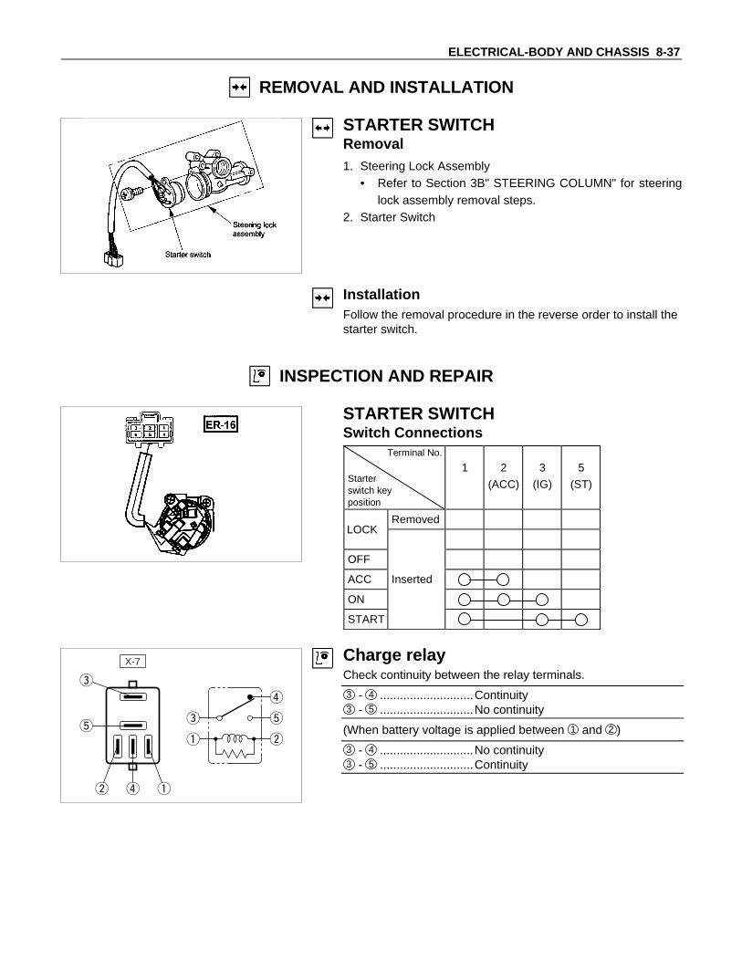
STARTER SWITCHRemoval1. Steering Lock Assembly
• Refer to Section 3B" STEERING COLUMN" for steeringlock assembly removal steps.
2. Starter Switch
InstallationFollow the removal procedure in the reverse order to install thestarter switch.
INSPECTION AND REPAIR
STARTER SWITCHSwitch Connections
Terminal No.
Starterswitch keyposition
1 2
(ACC)
3
(IG)
5
(ST)
Removed
OFF
ACC Inserted
ON
START
LOCK
X-7 Charge relayCheck continuity between the relay terminals.
3 - 4 ............................Continuity3 - 5 ............................No continuity
(When battery voltage is applied between 1 and 2 )
3 - 4 ............................No continuity3 - 5 ............................Continuity

8-38 ELECTRICAL-BODY AND CHASSIS
Starter relayCheck continuity between the relay terminals.
5 - 3 ............................Continuity5 - 1 ............................No continuity
(When battery voltage is applied between 2 and 4 )
5 - 3 ............................No continuity5 - 1 ............................Continuity

ELECTRICAL-BODY AND CHASSIS 8-39
LIGHTING
PARTS LOCATION
ER-11
P-7
ER-2
ER-3
ER-4
P-8 P-9 B-2
B-1
B-4
H-3H-7
ER-14I-14
I-4 I-3
I-13
I-6
I-12I-11I-10I-9
I-2
B-9
B-28
BD-4BD-5
RELAY&FUSE BOX(X-5,X-8,X-10,X-11)
H-1
B-26
H-16B-19
P-1P-6

8-40 ELECTRICAL-BODY AND CHASSIS
CIRCUIT DIAGRAMB
-23
B-2
1
B-2
2
P-8
P-6
BAT
TP
-1 P-9
P-7
P-7
: E
AR
TH
; B
OD
YP
-8 :
EA
RT
H ;
FR
AM
EP
-9 :
EA
RT
H ;
EN
GIN
E
30B/Y
9B/Y
0.5B/Y
8B/R
MA
INE
B-3
60A
X-1
12
X-1
11
3R3R
/W0.
5R/G
0.5R
/W
0.5R/B 0.5R/B
0.5R
/Y
0.5R
/Y
0.5Y
/L
1.25
W
0.5R
/B
0.5R
/W
0.5R
/Y0.
5R/Y
0.5B
IND
I. ; H
I-B
EA
M
1.25
R
RE
LAY
;LI
GH
TIN
G
X-1
13
X-1
15
X-1
04
X-1
02
X-1
03
X-1
01
X-1
05
0.85
B
0.5R
/G
1.25
W/L
0.85
R/G
0.85
R/G
0.85
R/G
0.5B
0.5B
0.5B
0.5B
0.5B
0.5B
I-14
4I-
145
0.5G
/R
SW
; F
OG
X-5
2X
-51
1.25
G/R
1.25W
0.5R/L
1.25W
RE
LAY
; TA
IL
X-5
3X
-55
H/L
AM
P-L
HE
-210
A
H/L
AM
P ;
LH
H/L
AM
P ;
RH
H/L
AM
P-R
HE
-310
A
FO
GE
-515
A
TAIL
E-1
110
A
LO HI
LO HI
ER
-33
ER
-31
ER
-32
H-13
H-12
RE
LAY
; D
IMM
ER
X-8
2
X-8
3
X-8
1
X-8
5
RE
LAY
; F
OG
FO
G L
AM
P-R
HER-4
1
ER-42
FO
G L
AM
P-L
H
B-41
H-1
23
H-3
4
H-1
1
H-3
7
B-42
0.5B
TAIL
LA
MP
-RH
TAIL
LA
MP
-LH
LIC
EN
SE
LA
MP
PO
SIT
ION
LA
MP
-LH
PO
SIT
ION
LA
MP
-RH
B-266
B-261
I-14
3
0.5G
/RI-
146
I-14
2
I-4
11
I-4
10
0.5G
/R0.
5B
B-286
B-281
0.5B
BD-41
BD-51
H-1611
0.5G
/R
0.5G
/R
0.5G/R
0.5G/R
0.5G
/R
0.5G
/R
0.5G
/R
0.5G
/R
0.5B
B-11
H-1
4
B-12
0.5B
ER-21
ER-22

ELECTRICAL-BODY AND CHASSIS 8-41
0.5R/L
0.5G/Y
0.5G
/R0.
5B
ME
TE
R IL
LUM
I
CLO
CK
ME
TE
R IL
LUM
I
HA
ZA
RD
SW
HE
ATE
R B
EZ
EL
I-313
I-48
0.5G
/R
I-41
I-48
0.5G
/R0.
5B
I-92
I-93
0.5G
/R
0.5G
/R
0.5B
I-123
I-121
0.5B
I-61
I-62
RR
WIP
ER
SW
RR
WA
SH
ER
SW
OD
OF
F S
W(A
/T)
0.5G
/R0.
5B
I-101
I-103
0.5G
/R0.
5B
0.5B
0.85
B
0.5B
0.5B
0.5B
0.5B
I-111
I-113
0.5G
/R
0.5R
/G
CO
MB
.SW
0.5B
0.5B
B-199
B-198
ER-14
10
H-7
15
ER-11
B-9EARTH ; E/R (RH)
EARTH ; E/R (LH)
I-13EARTH ; BODY (RH) 0.85B
I-2EARTH ; BODY (LH) 2B
1.25B
0.85B
0.85B
1.25B
HI
PASS
HS1
HS2
HU
E
TS
E
ER-1412
ER-1411
ER-1413

8-42 ELECTRICAL-BODY AND CHASSIS
TROUBLESHOOTING
HEADLIGHT1. Both the headlights (high and low beam) do not light
Checkpoint Trouble Cause Countermeasure
Repair the wiringPoor ground point contactNG
Repair open circuit orconnector contact
Repair open circuit
Repair or replace thecombination switch
Voltage between 12 ER-14 -ground
Open circuit between lightingrelay and lighting switch
Open circuit between batterypositive terminal and lightingrelay
Combination switch continuityPoor switch contact or swfaulty
Voltage between1 X-11 - ground and5 X-11 - ground
Reinstall or replace thelighting relay
Lighting relayPoor relay contact or relayfaulty
NG
NG
NG
NG
OK
OK
OK
OK
Ground point contact (ER-11)
Repair open circuitWiring continuity between10 ER-14 - ER-11
Open circuitNG
OK

ELECTRICAL-BODY AND CHASSIS 8-43
2. High or low beam does not light on both headlights
Checkpoint Trouble Cause Countermeasure
Repair or replace thecombination switch
Dimmer⋅passing switchcontinuity
Poor switch contact or switchfaulty
NG
Repair open circuit orconnector contact
Voltage between13 ER-14 - ground
Open circuit betweenheadlight and dimmer⋅passingswitch
NG
OK
3. RH (or LH) high and low beam does not light
Replace the headlight bulbHeadlight connector continuity Blown filament or air leakageNG
Repair or replace the wireand/or connector
Wiring continuity betweenconnector 3 ER-3 - fuse No.E-3 or 3 B-2 fuse No.E-2
Open circuit and/or poorconnector contact
NG
OK
Reinstall or replace fuse No.E-2 or No. E-3
Fuse No. E-2 (10A) orNo. E-3 (10A) (Relay and fusebox)(No. E-2: RH, No. E-3: LH)
Poor installation or blown fuseNG
OK
4. High or low beam does not light on one headlight (RH or LH)
Replace the headlightassembly
Headlight connector continuity Blown filamentNG
Repair open circuit orconnector contact
Wiring continuity betweenheadlight and dimmer⋅passingswitch
Open circuit betweenheadlight and dimmer⋅passingswitch
NG
OK

8-44 ELECTRICAL-BODY AND CHASSIS
5. Headlight does not go out
Checkpoint Trouble Cause Countermeasure
Replace the lighting relay
Lighting relay continuitybetween connector 1 X-11
- 2 X-11 (Should be nocontinuity)
Relay point fusedNG
Replay the combination switch
Lighting switch continuitybetween connector 2 ER-14
-10 ER-14 when switch isOFF(Should be no continuity)
Point fused or faultyNG
OK
OK
Repair short circuitbetween 5 X-11 - 12 ER-14
Check if headlight goes outwhen connector ER-14 isdisconnected
Short circuitNG
6. Insufficient headlight brightness
Replace the headlight bulbHeadlight bulb Bulb filament faultyNG
Repair the wiring
Dimmer⋅passing switchWire continuity between con-nector 10 ER-14 - ER-11
Poor ground point contactNG
OK
Clean the light lensHeadlight lens Lens dirtyNG
OK

ELECTRICAL-BODY AND CHASSIS 8-45
7. Passing light does not function when dimmer switch is operated
Checkpoint Trouble Cause Countermeasure
Repair or replace the dimmerswitch
Dimmer switch Poor switch point contactNG
Repair open circuit between5 X-11 - 13 ER-14
Voltage between13 ER-14 - ground (Shouldbe battery voltage present)
Open circuitNG
OK
8. Headlight beam does not change when dimmer switch is operated
Repair or replace the dimmerswitch
Dimmer switchLoose beam lever or foreignmaterial in switch
NG
8-46 ELECTRICAL-BODY AND CHASSIS
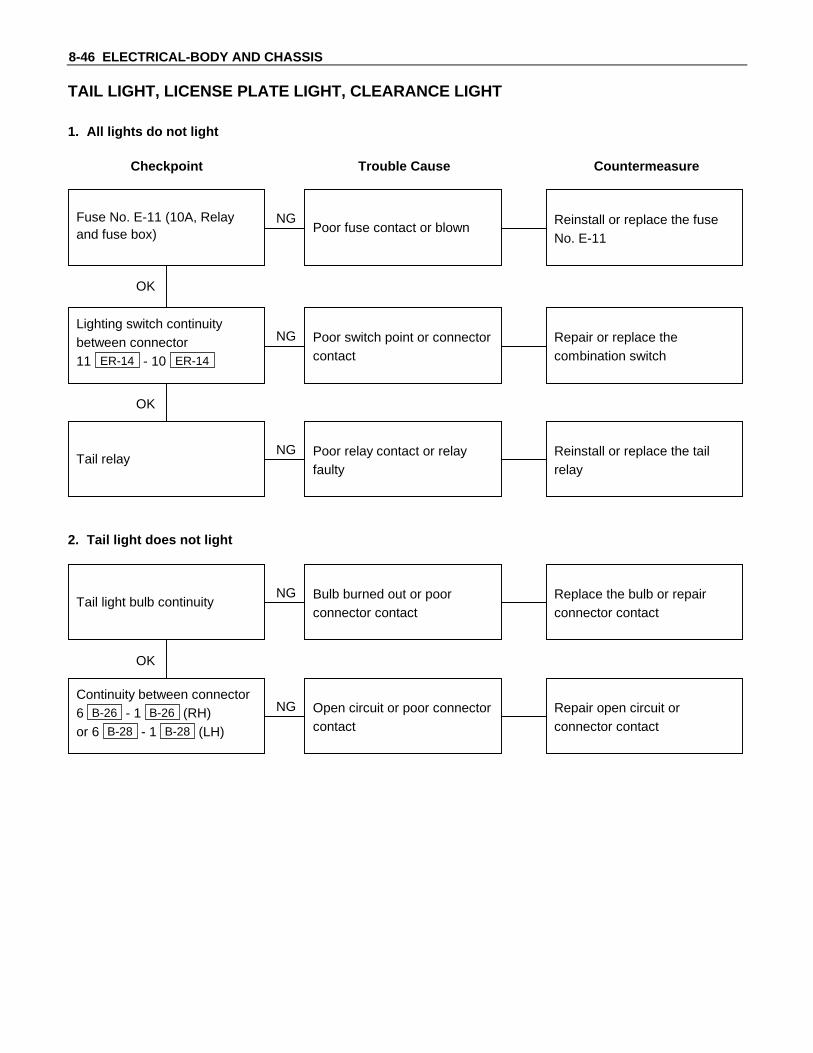
TAIL LIGHT, LICENSE PLATE LIGHT, CLEARANCE LIGHT
1. All lights do not light
Checkpoint Trouble Cause Countermeasure
Repair or replace thecombination switch
Lighting switch continuitybetween connector11 ER-14 - 10 ER-14
Poor switch point or connectorcontact
NG
Reinstall or replace the tailrelay
Tail relayPoor relay contact or relayfaulty
NG
OK
Reinstall or replace the fuseNo. E-11
Fuse No. E-11 (10A, Relayand fuse box) Poor fuse contact or blown
NG
OK
2. Tail light does not light
Replace the bulb or repairconnector contact
Tail light bulb continuityBulb burned out or poorconnector contact
NG
Repair open circuit orconnector contact
Continuity between connector6 B-26 - 1 B-26 (RH)or 6 B-28 - 1 B-28 (LH)
Open circuit or poor connectorcontact
NG
OK

ELECTRICAL-BODY AND CHASSIS 8-47
3. License plate light does not light
Checkpoint Trouble Cause Countermeasure
Repair open circuit orconnector contact
Continuity betweenconnector 1 BD-4 - 1 BD-5
Open circuit or poor connectorcontact
NG
Replace the bulb or repairconnector contact
License plate light bulbcontinuity
Bulb burned out or poorconnector contact
NG
OK
4. Clearance light does not light
Replace the bulb or repairconnector contact
Clearance light bulb continuityBulb burned out or poorconnector contact
NG

8-48 ELECTRICAL-BODY AND CHASSIS
REMOVAL AND INSTALLATION
HEADLIGHTRemoval1. Remove three bolts on the upper sides and bottom center
of the radiator grille, then remove the radiator grille.
2. Remove each bolt on the upper sides 1 , bottom sides 2 ,and bottom corner 3 of the front face panel, then removethe front defector panel.
3. Remove the headlight bolts.
4. Disconnect the headlight connector.5. Remove the headlight.

ELECTRICAL-BODY AND CHASSIS 8-49
InstallationFollow the removal procedure in the reverse order to install theheadlight.Pay close attention to the important points mentioned in thefollowing paragraphs.
ConnectorBe absolutely sure that the headlight connector is securelyconnected.This will prevent a contact and an open circuit.
LIGHTING SWITCHRemoval1. Remove the steering wheel 1 .
Refer to the “STEERING” Section of this manual.2. Remove the Instrument panel lower cover 2 .3. Remove the steering column cover 3 .
4. Disconnect the connector.5. Remove the lighting switch from the steering shaft.
InstallationFollow the removal procedure in the reverse order to install thelighting switch.Pay close attention to the important points mentioned in thefollowing paragraphs.
ConnectorBe absolutely sure that the lighting switch connector is securelyconnected.This will prevent a poor contact and an open circuit.
Wire HarnessDo not pinch the wire harnesses between the cluster and themeter hood during the cluster installation procedure.Wire damage will result.
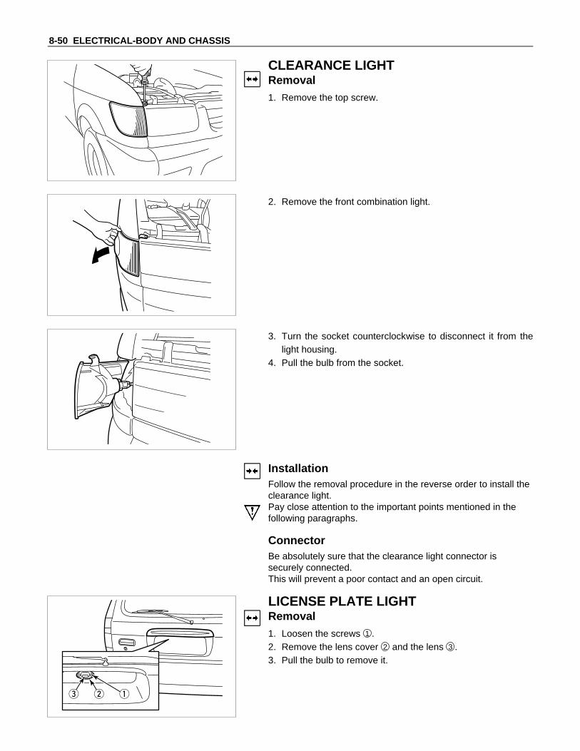
8-50 ELECTRICAL-BODY AND CHASSIS
CLEARANCE LIGHTRemoval1. Remove the top screw.
2. Remove the front combination light.
3. Turn the socket counterclockwise to disconnect it from thelight housing.
4. Pull the bulb from the socket.
InstallationFollow the removal procedure in the reverse order to install theclearance light.Pay close attention to the important points mentioned in thefollowing paragraphs.
ConnectorBe absolutely sure that the clearance light connector issecurely connected.This will prevent a poor contact and an open circuit.
LICENSE PLATE LIGHTRemoval1. Loosen the screws 1 .2. Remove the lens cover 2 and the lens 3 .3. Pull the bulb to remove it.

ELECTRICAL-BODY AND CHASSIS 8-51
InstallationFollow the removal procedure in the reverse order to install thelicense plate light.Pay close attention to the important points mentioned in thefollowing paragraphs.
BulbBe absolutely sure that the license plate light bulb is correctlyinstalled.This will prevent a poor contact and open circuit.
HEADLIGHT BEAM SWITCH(COMBINATION SWITCH)Removal1. Remove the screws on the lower part of the steering wheel.2. Remove the horn pad.3. Remove the wiring connector.4. Remove the steering wheel fixing nuts.5. Remove the steering wheel.
Refer to the "STEERING" Section of this manual.6. Remove the Instrument panel lower cover.7. Remove the steering column cover.8. Disconnect the connector.9. Remove the headlight beam switch (lever) from the steering
shaft (combination switch).
InstallationFollow the removal procedure in the reverse order to install theheadlight beam switch(lever).Pay close attention to the important points mentioned in thefollowing paragraphs.
ConnectorBe absolutely sure that the headlight beam switch connector issecurely connected.This will prevent a poor contact and an open circuit.
Wire HarnessDo not pinch the wire harnesses between the cluster and themeter hood during the cluster installation procedure.Wire damage will result.

8-52 ELECTRICAL-BODY AND CHASSIS
AIMING OF HEADLIGHT
Adjustment1. Check and adjust the tire inflation pressures, clean the headlights, park the vehicle on a level surface and make
sure that vehicle is loaded. Block the wheels. Release the parking brake and shift to Neutral. (N position for ATvehicles.)
2. Set the screen 3m away from front of the headlight. Adjust the screen so that the H-H, V-V line position isaligned with the headlight center (mark position). Align the C-C length with B-B length for the vehicle center line.If the cut line is not marked as shown in the figure of the following page, mark the cut line for adjustment 36mmbelow H-H line.
L
Ah2
C
C
h1
B
B
1 Screen 4 V-V line of screen
2 Cut line 5 Vehicle center line
3 H-H line of screen
Screen adjusting value
Distance C: C = 543mm
Distance A: A = 0.012×3000 = 36mm (1.2% downwards)
Note:
Measure at the following conditions:a. Carry out the aiming procedure on a level surface where it is able to darken.b. Headlight height "h1", distance from vehicle center line "B", and distance from screen "L" should be
measured from the center mark of the headlight.c. Always set the screen base line as:
h1 = h2B = C
ELECTRICAL-BODY AND CHASSIS 8-53
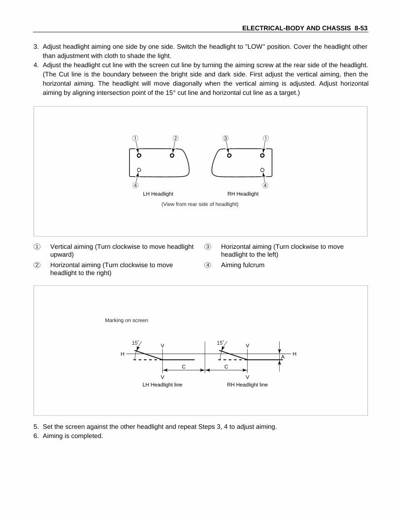
3. Adjust headlight aiming one side by one side. Switch the headlight to "LOW" position. Cover the headlight otherthan adjustment with cloth to shade the light.
4. Adjust the headlight cut line with the screen cut line by turning the aiming screw at the rear side of the headlight.(The Cut line is the boundary between the bright side and dark side. First adjust the vertical aiming, then thehorizontal aiming. The headlight will move diagonally when the vertical aiming is adjusted. Adjust horizontalaiming by aligning intersection point of the 15° cut line and horizontal cut line as a target.)
LH Headlight RH Headlight
(View from rear side of headlight)
1 Vertical aiming (Turn clockwise to move headlightupward)
3 Horizontal aiming (Turn clockwise to moveheadlight to the left)
2 Horizontal aiming (Turn clockwise to moveheadlight to the right)
4 Aiming fulcrum
V
H H
V
C
15˚
LH Headlight line
V
V
C
15˚
RH Headlight line
A
Marking on screen
5. Set the screen against the other headlight and repeat Steps 3, 4 to adjust aiming.6. Aiming is completed.

8-54 ELECTRICAL-BODY AND CHASSIS
INSPECTION AND REPAIR
LIGHTING SWITCHLighting Switch Connections
TerminalSW No.position
1 7 8
OFF
Tail
Headlight
HEADLIGHT BEAM SWITCHHeadlight Beam and Passing SwitchConnections
Terminal NO. 10 12 13
SW position HI PASS
HI
LO
At “Passing” Position
At “Dimmer” position
X-5 X-11LIGHTING RELAY, TAIL RELAYCheck continuity between the relay terminals.
3 - 5 .............................No continuity
(When battery voltage is applied between 1 and 2 )
3 - 5 .............................Continuity

ELECTRICAL-BODY AND CHASSIS 8-55
HAZARD WARNING FLASHER, TURN SIGNAL LIGHT, BACK UPLIGHT, HORN AND STOP LIGHT
PARTS LOCATION
ER-11
P-7
ER-1
ER-5
P-8P-9 B-3
H-3H-7
ER-14ER-14
I-4 I-3
I-13
I-16
I-12
B-9
B-28
BD-3
H-1
B-26
H-16
ER-16
TE-4TE-5*,TE-6*
H-6H-4*
*=M/T
ER-13
RELAY&FUSE BOX
P-1P-6

8-56 ELECTRICAL-BODY AND CHASSIS
CIRCUIT DIAGRAM
P-8
P-6BATTP-1
P-9 P-7
P-7 : EARTH ; BODYP-8 : EARTH ; FRAMEP-9 : EARTH ; ENGINE
30B
/Y
9B/Y
3W/B
5B/Y
MAINEB-360A
8B/R
3W 0.5G/W
IGNEB-240A
B
ACC
3B/Y
1.25R
0.85R/B
0.85G
IG
ST
ER-161
H-119
STOP ROOME-1010A
TURN,BACKC-515A
HORN,HAZARDE-415A
ER-163
SW ; STARTER
B-9
ER-11
EARTH ; E/R (LH)
EARTH ; E/R (RH)
I-13EARTH ; BODY (RH) 0.85B
0.5B
0.5B
0.85B
1.25B
0.85B
ER-14
6
I-12
5
I-12
3
I-12
7
ER-14
5
I-12
6
I-12
8
I-12
4
I-12
1
I-16
2
H-3
2
H-3
1
ER-14
4
RH LH
0.85G/B
0.85G/Y 0.85G/Y
0.85
G/Y
0.5R
/G
0.85
B/R
0.85
G
0.85
R/B
0.85
R/B
0.85
G
0.5G/R
0.5B
0.85G/W
0.85G/B
0.85G/W
0.85G/B
0.85G/W
COMB SW
BODY H,CONN(RH)
I-163
H-39
H-118
H-117
H-720
H-719
I-122
I-16
1
E B
L
FLASHER UNIT
(HAZARD)

ELECTRICAL-BODY AND CHASSIS 8-57
H-166
H-1611
0.85G/B
FRT.TURN S.LAMP-LH
FRT.TURN S.LAMP-RH
0.85G/W
0.5B
0.5B
B-3
1
B-3
2
ER
-11
ER
-1 2
0.85G/W
RR TURN S.LAMP-RH
METER INDI.-LH
0.85G/B
0.5B
0.5B
B-2
62
B-2
6 1
I-49
I-4 11
METER INDI.-RH
0.85G/W
I-312
RR TURN S.LAMP-LH
0.85G/B 0.5B
B-2
8 1
B-2
82
0.5G/Y
0.5G
/Y
0.5G/Y0.5G/Y
HI-MOUNT STOP LAMP
STOP LAMP-RH
0.5G/Y
0.5B
0.5B
0.85
B
0.5B
BD
-31
BD
-3 2
0.85R/Y0.85R/Y0.85R/B
0.85R/B
0.85R/Y
0.85R/B
0.85G
BACK UP LAMP-RH
BACK UP LAMP-LH
0.85R/Y
0.5B
0.5B
STOP LAMP-LH
0.5G/Y 0.5B
B-2
8 1
B-2
85
B-2
6 1
B-2
65
B-2
6 1
B-2
64
B-2
8 1
B-2
84
0.85B
0.85B
1.25B
0.85B
H-15
H-64
SW ; STOP LAMP
HORN
RELAY ; A/C
ER-51
ER-52
ER-147
SW ; HORN(COMB.SW)
0.5G/O
ER-132
ER-131
INHIBITOR SW(A/T)
TE-48
TE-46
R
H-410
TE-61
TE-51
SW ; BACK UP LAMP(M/T)
H-68
H-49
0.85R/B

8-58 ELECTRICAL-BODY AND CHASSIS
TROUBLESHOOTING
STOPLIGHT AND HIGH MOUNTED STOPLIGHT1. One side of stoplight does not light
Checkpoint Trouble Cause Countermeasure
Replace the bulb or repairconnector contact
Burned out bulb or poorconnector contact
NG
Repair open circuit orconnector contact
Repair open circuit orconnector contact
Open circuit or poor connectorcontact
LH:Continuity between5 H-1 - 5 B-28
RH:Continuity between5 H-1 - 5 B-26
Open circuit or poor connectorcontact
Continuity betweenB-9 - 1 B-28 (LH)T-6 - 1 B-26 (RH)
NG
NG
OK
OK
Stoplight bulb continuity
2. Both sides of stoplight do not light
Adjust the switch installationposition
Stop light switch (or brakeswitch) function
Incorrect the switch installationor adjustment
NG
Repair open circuit orconnector contact
Voltage between 5 B-28
ground or 5 B-26 - groundwith brake pedal depressed(Should be battery voltagepresent)
Open circuit or poor connectorcontact between stoplightswitch (or brake switch) andstoplight
NG
OK
Reinstall or replace fuse No.E-10 (10A)
Fuse No. E-10 (10A, Fuse andRelay box)
Poor fuse contact or blownNG
OK

ELECTRICAL-BODY AND CHASSIS 8-59
3. High mounted stoplight does not light
Checkpoint Trouble Cause Countermeasure
Repair or replace the highmounted stoplight
Continuity between 1 BD-3 -2 BD-3
High mounted stoplightmalfunction
NG
Repair an open circuit orconnector contact between1 BD-3 - 5 H-1
Voltage between 1 BD-3 -ground with brake pedaldepressed (Should be batteryvoltage present)
Open circuit or poor connectorcontact
NG
OK
Repair grounding point( B-9 ) contact
Grounding point ( B-9 ) Poor grounding point contactNG
OK

8-60 ELECTRICAL-BODY AND CHASSIS
TURN SIGNAL LIGHT AND HAZARD WARNING LIGHT1. Turn signal light does not light on both sides (RH and LH)
Checkpoint Trouble Cause Countermeasure
Replace the flasher unitFlasher unit malfunctionNG
Repair or replace thecombination switch
Turn signal switch continuitybetween connector6 ER-14 - 4 ER-14 and6 ER-14 - 5 ER-14 whenturn signal switch operates
Short circuit betweenconnector 2 I-16 - 3 I-16
when turn signal switchoperates with starter switchin “ON” position (Turnsignal light should be ON)
Poor switch point contact orfaulty switch
NG
OK
Reinstall or replace fuse No.C-5 (15A)
Fuse No. C-5 (15A, Fuse box)Poor fuse contact or blownfuse
NG
OK
OK
Repair open circuit orconnector contact
Continuity betweenconnector 1 I-2 -ground(Should be continuity)
Open circuit or poor connectorcontact
NG

ELECTRICAL-BODY AND CHASSIS 8-61
2. Turn signal light does not light on one side (RH or LH)
Checkpoint Trouble Cause Countermeasure
Repair open circuit orconnector contact
Open circuit or poor connectorcontact
NG
(LH)Continuity between1 B-3 - 5 ER-14 (FRT),2 B-28 - 5 ER-14 (RR)
(RH)Continuity between1 ER-1 - 4 ER-14 (FRT),2 B-26 - 4 ER-14 (RR)
Repair or replace thecombination switch
Turn signal switch continuityPoor switch point contact orfaulty switch
NG
OK
OK
Repair open circuit orconnector contact
Open circuit or poor connectorcontact
NG
3. Hazard warning light does not light
Repair or replace the hazardSW.
Hazard SW. malfunctionNG
Voltage between 2 I-12 -ground (Should be batteryvoltage present)
Hazard SW. continuity
Reinstall or replace the fuseNo. E-4 (15A)
Fuse No. E-4 (15A, Relay andfuse box)
Poor fuse contact or blownfuse
NG
OK
OK
Repair open circuit orconnector contact
Open circuit or poorconnector contact betweenfuse No. E-4 (15A) -2 I-12
NG
4. Flashing rate too fast (One side)
Replace the bulb or repairopen circuit
Inspect bulb Burned out bulbNG

8-62 ELECTRICAL-BODY AND CHASSIS
BACKUP LIGHT1. Backup light does not light on one side (RH or LH)
Checkpoint Trouble Cause Countermeasure
Repair grounding point contactPoor ground contactNG
Grounding point
Replace the bulb or repairconnector contact
Backup light bulb continuityBurned out bulb or poorconnector contact
NG
OK
2. Backup light does not light on both sides
Repair or replace the switchPoor switch point contact offaulty switch
NG
Voltage between 4 B-28
(4 B-26 ) - ground withstarter switch ON and shiftlever into reverse position(Should be battery voltagepresent)
Back up light switch (modeswitch) continuity
Reinstall or replace fuse No.C-5 (15A)
Fuse No. C-5 (15A, Fuse box) Poor fuse contact or blownfuse
NG
OK
OK
Repair open circuit orconnector contact
Open circuit or poor connectorcontact
NG

ELECTRICAL-BODY AND CHASSIS 8-63
HORN1. Both sides of horn do not sound
Checkpoint Trouble Cause Countermeasure
Repair the grounding pointPoor ground contactNG
Horn relay
Grounding point
Reinstall or replace fuse No.E-4 (15A)
Fuse No E-4 (15A, Relay andfuse box)
Poor fuse contact or blownfuse
NG
OK
OK
Reinstall or replace the hornrelay
Poor relay contact or faultyhorn relay
NG
OK
Remove steering pad andsteering wheel
Horn switch continuity
OK
Repair or replace the hornswitch
Poor switch point contact orfaulty switch
NG
Continuity between7 ER-14 - 1 ER-5
E-4 (15A) - 1 ER-5
OK
Repair open circuit orconnector contact
Open circuit or poor connectorcontact
NG

8-64 ELECTRICAL-BODY AND CHASSIS
2. One side of horn does not blow
Checkpoint Trouble Cause Countermeasure
Repair open circuit orreconnect the connector
Open circuit or poor connectorcontact
NGVoltage between 1 ER-5
- ground with horn switchdepressed (Should be batteryvoltage present)
Replace the horn assemblyHorn continuity betweenconnectors
Faulty horn assemblyNG
OK
3. Insufficient horn volume
Clean and/or remove theforeign material
Stain foreign material in thehorn
NGHorn
Recharge or replace thebattery
Battery condition Discharged batteryNG
OK
ELECTRICAL-BODY AND CHASSIS 8-65
REMOVAL AND INSTALLATION
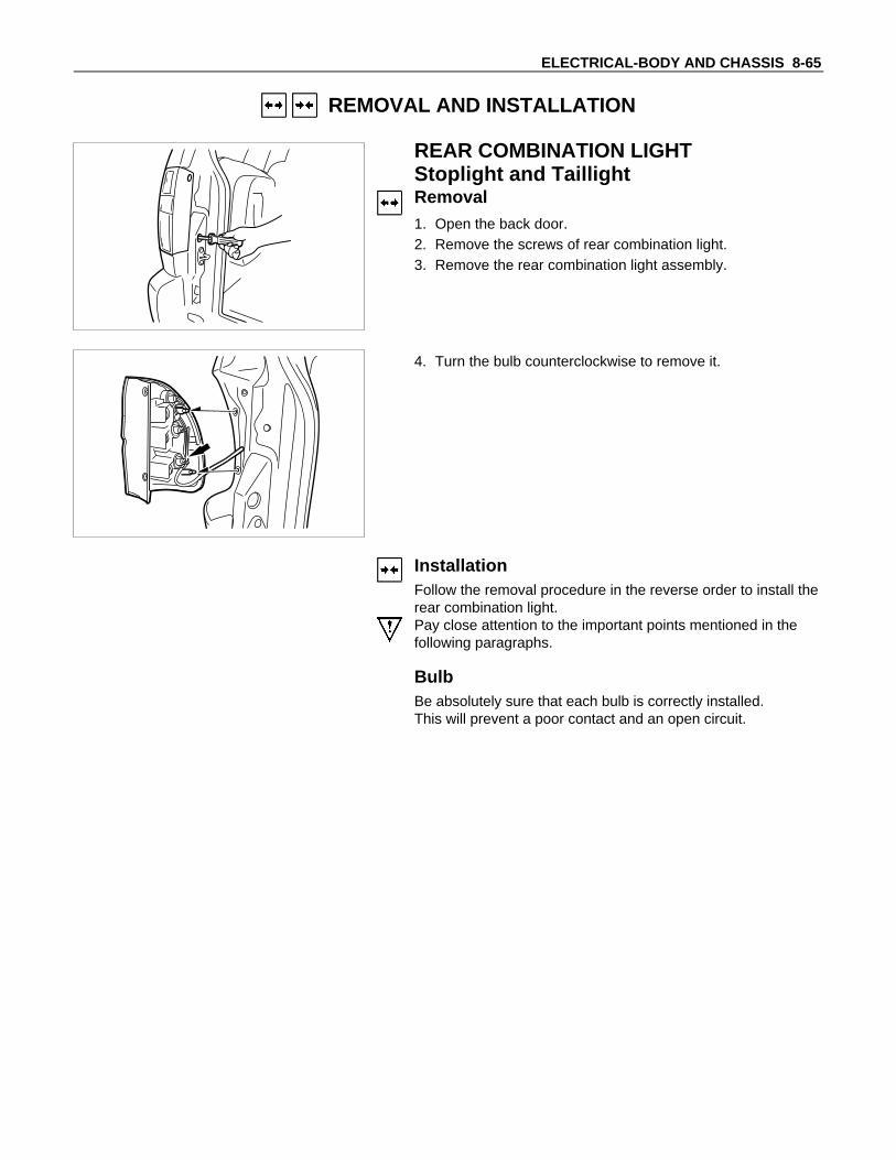
REAR COMBINATION LIGHTStoplight and TaillightRemoval1. Open the back door.2. Remove the screws of rear combination light.3. Remove the rear combination light assembly.
4. Turn the bulb counterclockwise to remove it.
InstallationFollow the removal procedure in the reverse order to install therear combination light.Pay close attention to the important points mentioned in thefollowing paragraphs.
BulbBe absolutely sure that each bulb is correctly installed.This will prevent a poor contact and an open circuit.

8-66 ELECTRICAL-BODY AND CHASSIS
FRONT TURN LIGHTRemoval1. Remove the top screw.2. Remove the front combination light.
3. Turn the socket counterclockwise to disconnect it from thelight housing.
4. Pull the bulb from the socket.
InstallationFollow the removal procedure in the reverse order to install thefront turn light.Pay close attention to the important points mentioned in thefollowing paragraphs.
BulbBe absolutely sure that the front turn light bulb is correctlyinstalled.This will prevent a poor contact and an open circuit.

ELECTRICAL-BODY AND CHASSIS 8-67
REAR COMBINATION LIGHTTurn Signal LightRemoval1. Open the back door.2. Remove the screws.3. Remove the rear combination light assembly.
4. Turn the bulb counterclockwise to remove it.
InstallationFollow the removal procedure in the reverse order to install therear combination light.Pay close attention to the important points mentioned in thefollowing paragraphs.
BulbBe absolutely sure that the rear combination light bulb iscorrectly installed.This will prevent a poor contact and an open circuit.

8-68 ELECTRICAL-BODY AND CHASSIS
TURN SIGNAL SWITCHRemoval1. Remove the steering wheel 1 .
Refer to the “STEERING” Section of this Manual.2. Remove the instruments panel lower cover 2 .3. Remove the steering column cover 3 .
4. Disconnect the connector.5. Remove the turn signal switch from the steering shaft.
InstallationFollow the removal procedure in the reverse order to install theturn signal switch (lever).Pay close attention to the important points mentioned in thefollowing paragraphs.
ConnectorBe absolutely sure that the turn signal switch connector issecurely connected.This will prevent a poor contact and at an open circuit.

ELECTRICAL-BODY AND CHASSIS 8-69
REAR COMBINATION LIGHTBack Up LightRemoval1. Open the back door.2. Remove the screws.3. Remove the rear combination light assembly.
4. Turn the bulb counterclockwise to remove it.
InstallationFollow the removal procedure in the reverse order to install therear combination light.Pay close attention to the important points mentioned in thefollowing paragraphs.
BulbsBe absolutely sure that each bulb is correctly installed.This will prevent a poor contact and an open circuit.

8-70 ELECTRICAL-BODY AND CHASSIS
HAZARD WARNING FLASHER SWITCHRemoval1. Instrument Panel Cluster Assembly
• Refer to Section 10 “BODY” for instrument panel clusterassembly removal steps.
2. Hazard Warning Switch• Disconnect the switch connector.• To remove the switch, push the lock from the back side
of the cluster assembly.
InstallationTo install, follow the removal procedure in the reverse order.
ConnectorBe absolutely sure that the hazard warning flasher switchconnector is securely connected.This will prevent a poor contact and an open circuit.
BACK UP LIGHT SWITCHRemoval1. Disconnect the connector 1 .2. Remove the back up light switch from the transmission 2 .
InstallationFollow the removal procedure in the reverse order to install theback up light switch.Pay close attention to the important points mentioned in thefollowing paragraphs.
Back up Light Switch ThreadsApply liquid gasket to the threaded portion and install the backup light switch.
ConnectorBe absolutely sure that the back up light connector is securelyconnected.This will prevent a poor contact and an open circuit.

ELECTRICAL-BODY AND CHASSIS 8-71
HORNRemoval1. Remove the radiator grille.
Refer to the “HEADLIGHT” removal procedure.2. Loosen the horn bolt.3. Disconnect the horn connector.
InstallationFollow the removal procedure in the reverse order to install thehorn.Pay close attention to the important point mentioned in thefollowing paragraphs.
ConnectorBe absolutely sure the horn connector is securely connected.This will prevent a poor contact and open circuit.
1
HORN SWITCHRemoval1. Remove the screws on the lower part of the steering wheel.2. Remove the horn pad 1 .3. Remove the horn wiring connector.
3 2
4. Remove the steering wheel nut 2 .5. Remove the steering wheel 3 .6. Remove the connector.7. Remove the horn switch (combination switch).
InstallationFollow the removal procedure in the reverse order to install thehorn switch.Pay close attention to the important points mentioned in thefollowing paragraphs.
Steering Wheel NutTighten the nut to the specified torque.Steering Wheel Nut Torque N⋅m (kgf⋅m/lb⋅ft)
34.3±4.9 (3.5±0.5 / 25±3.6)

8-72 ELECTRICAL-BODY AND CHASSIS
INSPECTION AND REPAIR
TURN SIGNAL SWITCHLighting Switch Connections
Terminal No.
SW position6 5 4
Left
Neutral
Right
Turningdirection
HAZARD WARNING FLASHER SWITCHHazard Warning Flasher Switch Connections
TerminalNo.
SW position
4 5 6 7 8 2 1 3
ON
OFF

ELECTRICAL-BODY AND CHASSIS 8-73
WINDSHIELD WIPER AND WASHER
PARTS LOCATION
ER-11
P-7
P-8 P-9
H-3H-7
ER-15
I-13B-9
H-1ER-10
H-16
B-7ER-16
I-11
I-10
BD-10
BD-2RELAY&FUSE BOX
P-1P-6

8-74 ELECTRICAL-BODY AND CHASSIS
CIRCUIT DIAGRAM
P-8
P-2BATTP-1
P-9 P-7
P-7 : EARTH ; BODYP-8 : EARTH ; FRAMEP-9 : EARTH ; ENGINE
30B
/Y
9B/Y
5B/Y
IGN.EB-240A
8B/R 3W/B B
ACC
3B/Y 1.25LG/W
IG
ST
ER-161
FRT WIPERC-320A
ER-163
SW ; STARTER
3B/Y
COMB.SW
0.5W/L 0.5W/L
RR WIPERC-410A
H-315
BD-21
ER-11
B-9
EARTH ; E/R (RH)
EARTH ; E/R (LH)
I-13EARTH ; BODY (RH) 0.85B
1.25B
0.85B
0.85B
1.25B
HI
LO INT
OF
F
WA
SH
ER
M M
ER-15
1
ER-15
3
ER-15
7
ER-15
4
H-1
8
B-7
3
H-1
9
H-1
6
H-1
7
B-7
2
BD-2
3
BD-2
2
I-10
7
I-10
6
ER-15
9
H-163
H-7
2
H-169
H-7
1
I-10
3
I-10
1
H-16
11
B-7
1
B-7
6
B H L
E
AS
1.25
L/Y
1.25
L1.
25B
0.5B
0.5B
0.5B
0.5B
0.5W
/L
0.5L
/O0.
5L/O
0.5B
0.5O
0.5O
0.5G
/R
0.5G/R
FU
SE
E-1
1TA
IL0.5W
/L
0.5W
/L
0.5W
/L
0.5B
0.5B
0.85B
0.5B1.25
B
1.25
L/Y
1.25
LG/W
1.25
L/R
1.25
LG/W
1.25
L/R
FR
T W
IPE
R M
OTO
R
RR
WIP
ER
MO
TOR
RR
WA
SH
ER
MO
TOR
FR
T W
AS
HE
R M
OTO
R
SW
; R
R W
IPE
R
1.25
L
0.85
L/B
B-75
ER-152
ER-10
2
ER-10
1
MBD-10
1
BD-10
2
M
I-11
6
I-11
4
I-11
3
I-11
1
SW
; R
R W
AS
HE
RH-16
10
H-7
3

ELECTRICAL-BODY AND CHASSIS 8-75
TROUBLESHOOTING
WINDSHIELD WIPER1. Wiper does not operate at any switch position
Checkpoint Trouble Cause Countermeasure
Reinstall or replace the fuseNo. C-3 (20A)
Poor fuse contact or blownNG
Repair open circuit orconnector contact
1. Wiper motor function whenconnecting the motorconnector 2 B-7 to thebattery (+) terminal, and 3
B-7 to the (-) terminal(Should the wiper motorrotate at a low speed)
2. Wiper motor function whenconnecting the motorconnector 1 B-7 to thebattery (+) terminal, 3 B-7
to the (-) terminal (Shouldthe wiper motor rotate at ahigh speed)
Voltage between 9 ER-15
and the ground (Should bebattery voltage present)
Open circuit or poor connectorcontact
Replace the wiper & washerSW.
Continuity in the wiper &washer SW.
SW. malfunctionNG
NG
OK
OK
Fuse No. C-3 (20A)
Repair grounding point( B-9 ) contact
Grounding point ( B-9 ) Poor grounding point contactNG
OK
OK
Replace the wiper motorWiper motor malfunctionNG
Repair open circuit orconnector contact
Continuity between 3 B-7
and B-9
Open circuit or poor connectorcontact
NG
OK

8-76 ELECTRICAL-BODY AND CHASSIS
2. Wiper does not operate at “ INT “ position
Checkpoint Trouble Cause Countermeasure
Replace the wiper & washerSW.
SW. malfunctionNG
Repair grounding point contactGrounding point B-9 Poor rounding point contactNG
OK
OK
Continuity between the wiper& washer SW connectorterminals 9 ER-15 and1 ER-15 at the “INT” position
Replace the intermittent relayIntermittent relay function Relay malfunctionNG
3. Wiper does not operate at “LO” position
Replace the wiper motor
Wiper motor function1. Disconnect the wiper &
washer SW. connector2. Turn the starter SW. on3. Short-circuit between the
wiper & washer SW.harness side connectorterminals.9 ER-15 and 3 ER-15
4. Check to see if the wipermotor rotates at a lowspeed
Wiper motor malfunctionNG
Replace the wiper & WasherSW.
Wiper & washer SW. function SW. malfunctionNG
OK

ELECTRICAL-BODY AND CHASSIS 8-77
4. Wiper does not operate at “HI” position
Checkpoint Trouble Cause Countermeasure
Repair open circuit orconnector contact
Open circuit or poor connectorcontact
NG
Replace the wiper motor
Wiper motor function whenconnecting the motorconnector 1 B-7 to thebattery (+) terminal, and3 B-7 to the (-) terminal(Should the wiper motor rotateat a high speed)
Wiper motor malfunctionNG
OK
Continuity between the wiper& washer SW. connectorterminals 4 ER-15 and9 ER-15 at the “HI” position
Repair open circuit orconnector contact
Continuity between 9 ER-15
and 1 B-7
Open circuit or poor connectorcontact
NG
OK
5. Rotation of the wiper motor does not stop
Replace the wiper & washerSW.
SW. malfunctionNG
OK
Continuity in the wiper &washer SW.
Replace the wiper motorWiper motor function Wiper motor malfunctionNG

8-78 ELECTRICAL-BODY AND CHASSIS
6. Auto-stop function of the wiper motor does not operate
Checkpoint Trouble Cause Countermeasure
Repair open circuit orconnector contact
Open circuit or poor connectorcontact
NG
Repair open circuit orconnector contact
Open circuit or poor connectorcontact
NG
Continuity between theintermittent relay harness sideconnector 6 B-7 and thewiper motor harness sideconnector 5 B-7
Replace the intermittent relayRelay malfunctionNGIntermittent relay function
Wiper motor function1. Disconnect the wiper motor
connector2. Connect the motor
connector 2 B-7 to thebattery (+) terminal and3 B-7 to the (-) terminal,and then change theconnection of the battery (+)terminal to the connector6 B-7 while the motorrotating at a low speed
3. Check to see if the wipermotor stops at the auto stopposition when connectingthe connector terminals2 B-7 and 5 B-7 in thiscondition
Continuity between the wiper& washer SW. connectorterminals 3 ER-15 at the“OFF” position
OK
Replace the wiper motorWiper motor malfunctionNG
Repair an open circuit or apoor connection of theconnectors between the fuseNo. C-3 (20A)
Voltage between the wipermotor harness side connectorterminal 6 B-7 and theground (Should be batteryvoltage present)
Open circuit or poor connectorcontact
NG
OK
OK
OK

ELECTRICAL-BODY AND CHASSIS 8-79
WASHER1. Washer motor does not operate
Checkpoint Trouble Cause Countermeasure
Reinstall or replace the fuseNo. C-3 (20A)
Poor fuse contact or blownNG
Repair or an open circuit or apoor connection of theconnectors between 1 ER-10
and 7 ER-15
Open circuit or poor connectorcontact
NG
Voltage between the washermotor harness side connectorterminal 1 ER-10 and theground when the washerbutton is depressed (Shouldbe battery voltage present)
Repair grounding point( ER-11 ) contact
Poor grounding point contactNGGrounding point ( ER-11 )
Replace the washer motorMotor malfunctionNG
Washer motor function whenconnecting the motor sideconnector 1 ER-10 to thebattery (+) terminal, and theconnector 2 ER-10 to the (-)terminal (Should the washermotor rotate)
OK
Repair open circuit orconnector contact
Open circuit or poor connectorcontact
NGContinuity between 2 ER-10
and ER-11
OK
Continuity between the wiper& washer SW. side connectorterminals 9 ER-15 and7 ER-15 when the washerbutton is depressed
Fuse No. C-3 (20A)
OK
Replace the wiper & washerSW.
SW. malfunctionNG
Repair or an open circuit or apoor connection of theconnectors between the fuseNo. C-3 (20A) and 9 ER-15
Voltage between the wiper &washer SW. harness sideconnector terminal 9 ER-15
and the ground (Should bebattery voltage preset)
Open circuit or poor connectorcontact
NG
OK
OK
OK
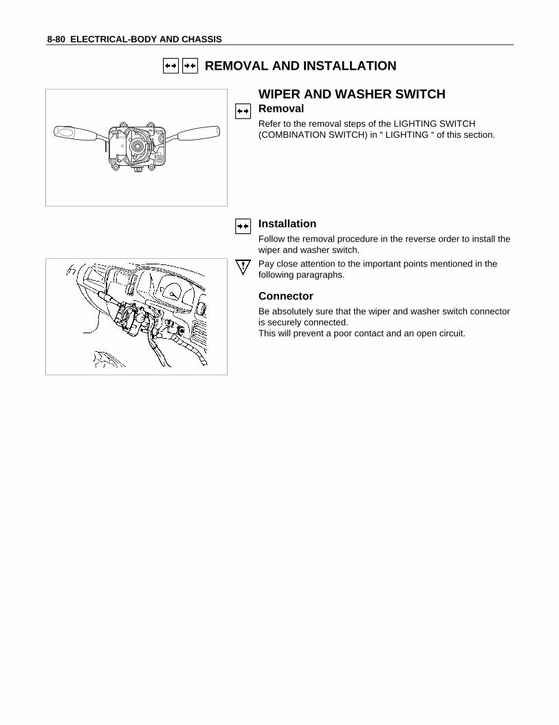
8-80 ELECTRICAL-BODY AND CHASSIS
REMOVAL AND INSTALLATION
WIPER AND WASHER SWITCHRemovalRefer to the removal steps of the LIGHTING SWITCH(COMBINATION SWITCH) in “ LIGHTING “ of this section.
InstallationFollow the removal procedure in the reverse order to install thewiper and washer switch.
Pay close attention to the important points mentioned in thefollowing paragraphs.
ConnectorBe absolutely sure that the wiper and washer switch connectoris securely connected.This will prevent a poor contact and an open circuit.
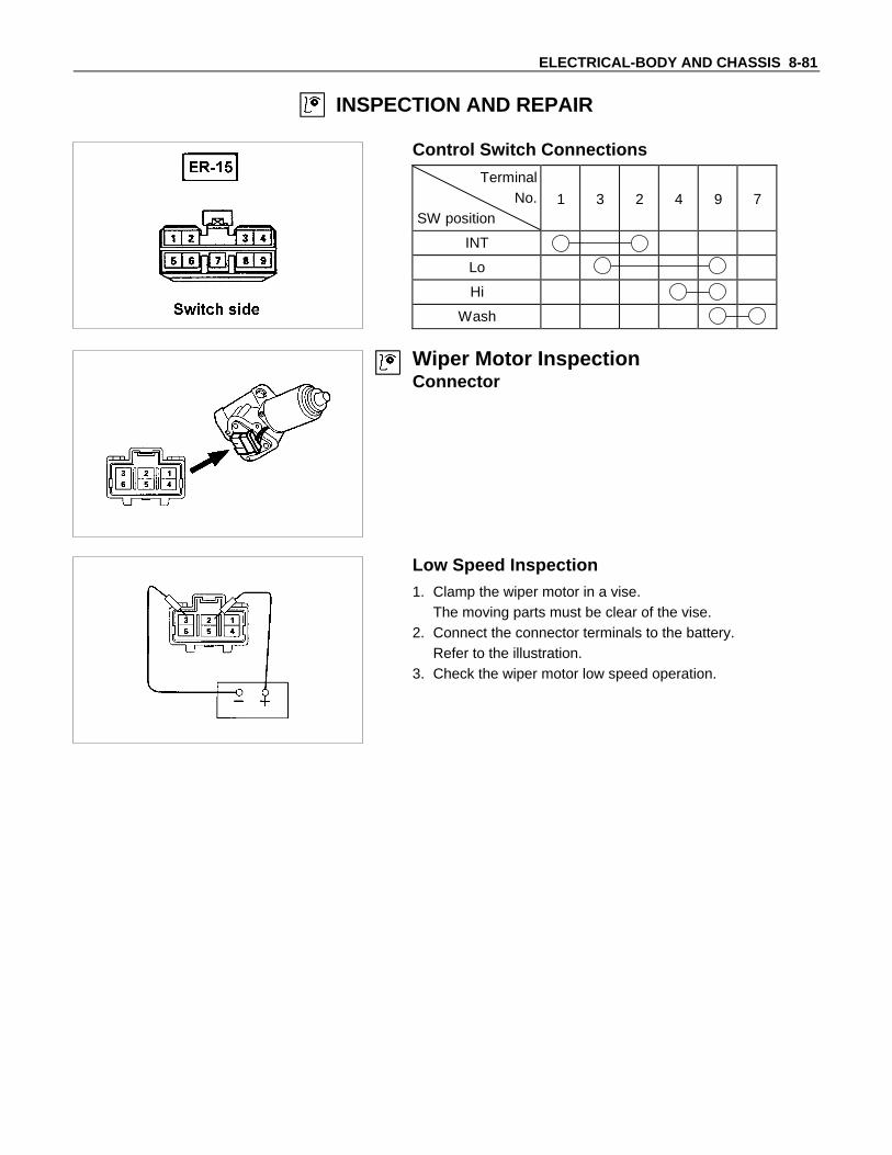
ELECTRICAL-BODY AND CHASSIS 8-81
INSPECTION AND REPAIR
Control Switch Connections
TerminalNo.
SW position1 3 2 4 9 7
INT
Lo
Hi
Wash
Wiper Motor InspectionConnector
Low Speed Inspection1. Clamp the wiper motor in a vise.
The moving parts must be clear of the vise.2. Connect the connector terminals to the battery.
Refer to the illustration.3. Check the wiper motor low speed operation.

8-82 ELECTRICAL-BODY AND CHASSIS
High Speed Inspection1. Clamp the wiper motor in a vise.
The moving parts must be clear of the vise.2. Connect the connector terminals to the battery.
Refer to the illustration.3. Check the wiper motor high speed operation.
Auto-Stop Inspection1. Clamp the wiper motor in a vise.
The moving parts must be clear of the vise.2. Connect the connector terminals to the battery.
Refer to the illustration.3. Check the wiper motor low speed operation.4. Disconnect the positive battery terminal.
This will stop the motor.
5. Connect the connector terminals No. 2 and No. 5 with alead wire.Refer to the illustration.
6. Reconnect the positive battery terminal to connectorterminal No. 6.This will restart the motor.Refer to the illustration.
7. Check the auto-stop operation.
Washer Motor Inspection1. Fill the washer tank with washing solution.2. Disconnect the motor connector.3. Apply battery voltage to the washer motor connector.4. Check the washer motor operation.

ELECTRICAL-BODY AND CHASSIS 8-83
WIPER MOTOR AND LINKAGERemoval1. Disconnect the wiper motor connector 1 .2. Remove the wiper motor bracket screws 2 .
3. Disconnect the wiper motor from the wiper linkage at thecrank arm 3 .
4. Disconnect the wiper arm nut cap 4 .
5. Remove the wiper arm nut 5 .6. Remove the wiper arm with blade.
7. Remove the vent cowl cover 6 .

8-84 ELECTRICAL-BODY AND CHASSIS
8. Remove the wiper linkage 7 from the access hole.
InstallationFollow the removal procedure in the reverse order to install thewiper motor and linkage.Pay close attention to the important points mentioned in thefollowing paragraphs.
Wiper LinkageTake care not to scratch the painted surfaces of the body wheninstalling the wiper linkage to the body.In case crank arm of wiper motor is removed, confirm theposition of auto stop prior to reinstall the crank arm to the wipermotor.Crank Arm Nut Torque N⋅m (kgf⋅m/lb⋅ft)
22.1 ± 3.4 (2.25 ± 0.35/16.3 ± 2.5)
Wiper Blade PositionConfirm the auto stop position of wiper motor prior to theinstallation of the wiper blade and arm.The distance between the vent cowl cover rubber seal 1 andthe wiper blade edge 2 is about 45 mm(1.8 in).
Wiper Arm NutTighten the wiper arm nut to the specified torque.Wiper Arm Nut Torque N⋅m (kgf⋅m/lb⋅ft)
Front wiper 31.4 +3.9−4.9 (3.2 +0.4
−0.5 /23.1 +2.9−3.6 )

ELECTRICAL-BODY AND CHASSIS 8-85
Windshield Washer SprayBe sure that the engine hood 1 is completely closed beforechecking the windshield washer spray adjustment.Windshield Washer Spray Position mm(in)
A Approximately 300 (11.8)
ConnectorBe absolutely sure that the wiper motor connector is securelyconnected.This will prevent a poor contact and an open circuit.
Note:Windshield wiper arm and blade assembly configurationsare different for the right-hand and left-hand side of thevehicle.Be careful not to confuse the right-hand and left-hand sideassemblies.
WASHER TANK MOTORRemoval1. Remove the washer tank bolts.2. Disconnect the connector 1 .3. Disconnect the water hose 2 .
4. Remove the washer tank motor 3 .
InstallationFollow the removal procedure in the reverse order to install thewasher tank motor.Pay close attention to the important points mentioned in thefollowing paragraphs.
ConnectorBe absolutely sure that the washer tank motor connector issecurely connected.This will prevent a poor contact and an open circuit.
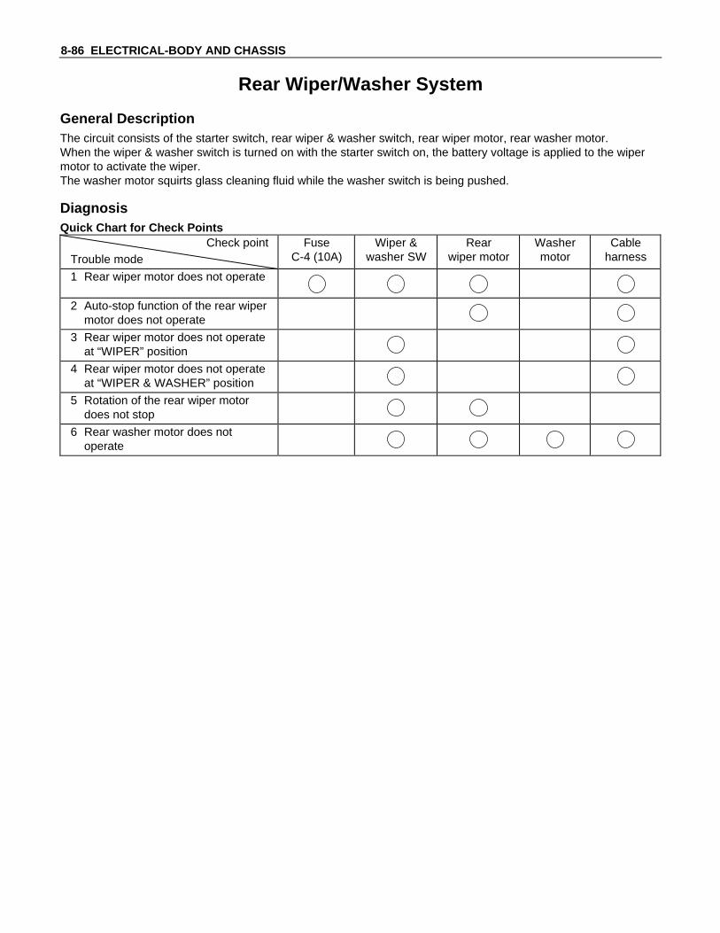
8-86 ELECTRICAL-BODY AND CHASSIS
Rear Wiper/Washer System
General DescriptionThe circuit consists of the starter switch, rear wiper & washer switch, rear wiper motor, rear washer motor.When the wiper & washer switch is turned on with the starter switch on, the battery voltage is applied to the wipermotor to activate the wiper.The washer motor squirts glass cleaning fluid while the washer switch is being pushed.
DiagnosisQuick Chart for Check Points
Check pointTrouble mode
FuseC-4 (10A)
Wiper &washer SW
Rearwiper motor
Washermotor
Cableharness
1 Rear wiper motor does not operate
2 Auto-stop function of the rear wipermotor does not operate
3 Rear wiper motor does not operateat “WIPER” position
4 Rear wiper motor does not operateat “WIPER & WASHER” position
5 Rotation of the rear wiper motordoes not stop
6 Rear washer motor does notoperate

ELECTRICAL-BODY AND CHASSIS 8-87
1. Rear Wiper Motor Does Not Operate
YES
• Disconnect the connector of the rear wiper & washer switch• Is the continuity in the rear wiper & washer switch normal?
Is B-9 grounded securely?
Replace fuse C-4 (10A)
• Is fuse C-4 (10A) normal?
Repair a poor connection at the connectors or an open circuit betweenrear wiper switch terminal 7 I-10 and rear wiper motor terminal 2 BD-2
• Disconnect the connectors of the rear wiper motor• With the motor side connector 2 BD-2 connected to the battery (+)
terminal and the connector 3 BD-2 to the (-) terminal, does the motorrotate?
• Turn the starter SW ON• Is the battery voltage applied between the rear wiper &
washer switch harness side connector terminal 6 I-10 andground?
YES
YES
YES
YES
NO
Ground it securely
NO
Repair or replace the rear wiper motor
NO
Repair a poor connection at theconnectors or an open circuit betweenfuse C-4 (10A) and 6 I-10
NO
NO
Repair or replace the rear wiper &washer switch

8-88 ELECTRICAL-BODY AND CHASSIS
2. Auto-Stop Function of The Rear Wiper Motor Does Not Operate
• Disconnect the connector of the rear wiper motor
• Connect the motor side connector 2 BD-2 to the battery (+) terminal andthe terminal 3 BD-2 to the (-) terminal
• While rotating the motor, change the connection of the battery (+) terminalto the connector 1 BD-2
• Does the rear wiper stop at the auto-stop position in this condition?
Repair a poor connection at the connectors or an open circuit betweenthe fuse C-4 (10A) and rear wiper motor terminal 2 BD-2
• Turn the start switch ON
• Is the battery voltage applied between the rear wiper motor harnessside connector 1 BD-2 and the ground?
YES
YES
NO
Repair a poor connection at theconnectors or an open circuit betweenthe fuse C-4 (10A) and 1 BD-2
NO
Repair or replace the rear wiper motor
3. Rotation of The Rear Wiper Motor Does Not Stop
• Is the continuity in the rear wiper switch normal?
Repair or replace the RR wiper motor
YES NO
Repair or replace the rear wiper switch

ELECTRICAL-BODY AND CHASSIS 8-89
4. Rear Washer Motor Does Not Operate
• Disconnect the connector of the rear wiper & washer switch• With the switch set at “WASH” position, is there continuity
between the switch connector terminals 4 I-11 and 6 I-11 ?
Replace the fuse
• Is B-9 grounded securely?
• Is fuse C-4 (10A) normal?
Repair a poor connection at the connectors or an open circuit between1 BD-10 and B-9
• Disconnect the connector of the rear washer motor• Turn the starter switch ON• With the rear wiper & washer switch set at “WASH” position, is the
battery voltage applied between the rear washer motor harness sideconnector 2 BD-10 and ground?
• Turn the starter switch ON• Is the battery voltage applied between the rear wiper & washer
switch harness side connector 4 I-11 and ground?
YES
YES
YES
Ground it securely
NO
Replace the rear washer motor
NO
Repair a poor connection at theconnectors or an open circuit betweenthe fuse C-4 (10A) and 4 I-11
NO
NO
Repair or replace the switch
• Connect the motor side connector terminal2 BD-10 to the battery (+) terminal and 1 BD-10 to the (-)terminal
• Does the motor operate?
YES NO
Repair a poor connection at theconnectors or an open circuit between 2BD-10 and 6 I-11
YES
YES NO

8-90 ELECTRICAL-BODY AND CHASSIS
Rear washer switch
Rear wiper switch REAR WIPER AND WASHER SWITCHRemoval1. Disconnect the battery ground cable.2. Remove the switch by pushing the lock with the tip of a
screwdriver.3. Disconnect the switch connector.
InstallationTo install, follow the removal steps in the reverse order, notingthe following point:1. Push the switch with your fingers until it locks securely.
Body harness
REAR WIPER MOTORRemoval1. Disconnect the battery ground cable.2. Remove the back door trim pad.3. Remove the wiper arm/blade.
Refer to the removal steps of the Rear Wiper Arm/Blade inthis section.
4. Disconnect the connector and remove the wiper shaft nut,remove the fixing screw and nut then remove the rear wipermotor(1).
212mm(8.35in)
InstallationTo install, follow the removal steps in the reverse order, notingthe following points.1. Before installing the wiper arm/blade to the motor shaft,
confirm that the motor stops at the auto-stop position.2. Tighten the motor shaft nut to the specified torque.
N.m (kgf.m/lb.ft)4.90 ± 0.98 (0.50 ± 0.10/43.40 ± 8.68)
3. Install the wiper arm so that the blade parellel, and positionthe blade 212mm (8.4 in) from center of wiper shaft.
4. Tighten the wiper arm nut to the specified torque.
N.m (kgf.m/lb.ft)19.6+3.92
−2.94 (2.0 +0.40−0.30/173.6+34.7
−26.0)

ELECTRICAL-BODY AND CHASSIS 8-91
REAR WASHER MOTORRemoval1. Disconnect the battery ground cable.2. Remove the back door trim pad.3. Remove two screws, disconnect the connector, remove the
washer hose and then remove the rear washer tank(2).4. Pull out the rear washer motor(1) from the washer tank.
InstallationTo install, follow the removal steps in the reverse order.
REAR WIPER ARM/BLADERemoval1. Remove the arm nut cover(1).2. Remove the arm nut(2).3. Remove the wiper arm/blade(3).
InstallationRefer to the installation steps of the Rear Wiper Motor inWiper/Washer System section.
REAR WASHER NOZZLERemoval1. Disconnect the hose(3).2. Remove the lock nut(2), and then remove the washer
nozzle(1).
InstallationTo install, follow the removal steps in the reverse order.
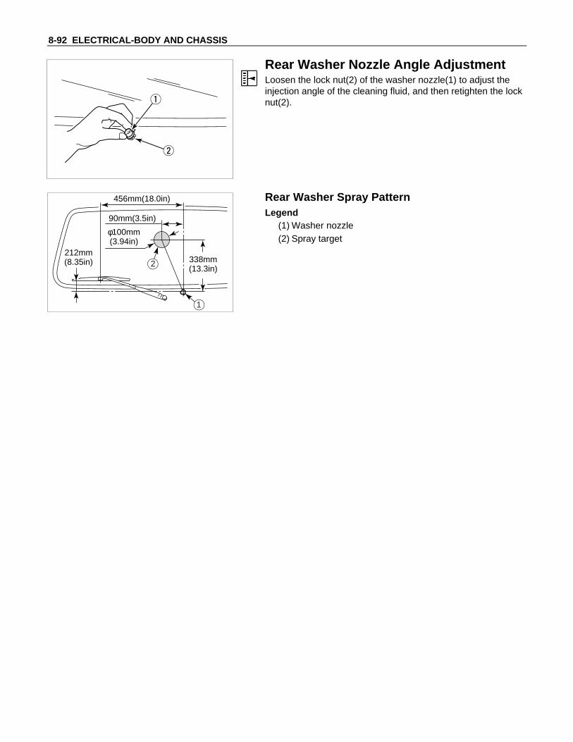
8-92 ELECTRICAL-BODY AND CHASSIS
Rear Washer Nozzle Angle AdjustmentLoosen the lock nut(2) of the washer nozzle(1) to adjust theinjection angle of the cleaning fluid, and then retighten the locknut(2).
212mm(8.35in) 338mm
(13.3in)
φ100mm(3.94in)
456mm(18.0in)
90mm(3.5in)
1
2
Rear Washer Spray PatternLegend
(1) Washer nozzle(2) Spray target
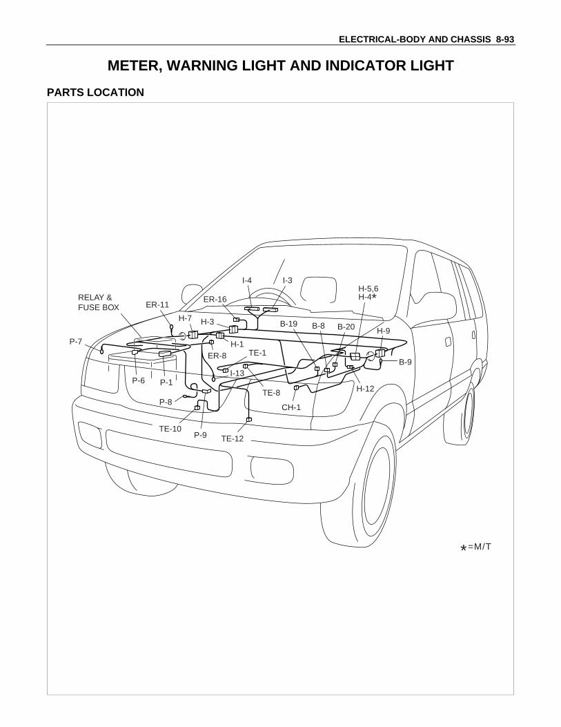
ELECTRICAL-BODY AND CHASSIS 8-93
METER, WARNING LIGHT AND INDICATOR LIGHT
PARTS LOCATION
ER-11
P-7
P-8
P-9TE-10
TE-1
TE-8
CH-1
TE-12
H-3
I-13
H-1ER-8
ER-16
H-7
I-4 I-3
H-12
B-20B-8B-19
B-9
H-9
H-5,6H-4*
*=M/T
RELAY &FUSE BOX
P-1P-6
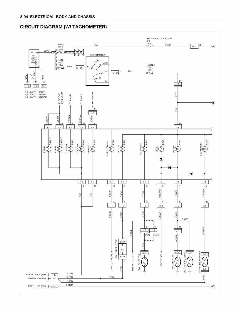
8-94 ELECTRICAL-BODY AND CHASSIS
CIRCUIT DIAGRAM (W/ TACHOMETER)
OIL
PR
ES
S 1.4W
OD
OF
F 1.4W
I-4
1
I-3
13
I-4
9
I-3
12
I-4
10
H-9
10
H-9
9
H-9
12
H-9
11
H-3
5
H-7
13
H-1
20
I-3
10
H-3
7
I-4
8
I-4
11
I-4
13
I-3
9
I-3
6
I-3
5
I-3
4
I-3
3
P-8
P-6BATTP-1
P-9 P-7
P-7 : EARTH ; BODYP-8 : EARTH ; FRAMEP-9 : EARTH ; ENGINE
30B
/Y
9B/Y
3W/B
5B/Y
0.5G
/RIL
LUM
I. 3.4W
x2
FU
SE
E-1
0(T
AIL
LA
MP
)
TU
RN
-LH
TU
RN
-RH
H/L
AM
P-L
H
0.5G
/R
0.85
G/B
0.85
G/W
0.5R
/Y
MAINEB-360A
8B/R
3W 0.85R
IGNEB-240A
B
ACC
3B/Y
0.5Y
0.5Y
IG
ST
ER-161
AUDIO(B),CLOCK,ROOME-915A
METERC-110A
ER-163
SW ; STARTERIL
LUM
I. 3.4W
x2
TU
RN
-LH 1.
4W
TU
RN
-RH
0.5B
0.5B
0.5O
/B0.
5O/B
0.5O
/L
0.5S
B0.
5SB
0.85
W/R
0.85
W/R
0.5O
/L
0.5O
/L
1.25
B
0.5B
0.5B
0.5B
1.4W
HI-
BE
AM 1.
4W
CH
EC
K T
RA
NS
1.2W
CO
NT
; T
CM
(19)
RE
LAY
; O
D O
FF
CH
G.R
ELA
Y
ER-11
I-13
EARTH ; E/R (RH)
EARTH ; BODY (RH)
B-9EARTH ; E/R (LH)
0.85B
0.5B/P
1.25B
0.85B
H-314
CH
G.
1.4W
BR
AK
E
1.4W
SE
DIM
EN
TE
R
1.4W
B-19
5
B-19
1
SW
; S
HIF
T L
EV
ER
H-53
H-42
SW
; O
IL P
RE
SS
.
SW
; V
AC
UU
M
TE-12
0.5P
/B0.
5P/B
0.5L
G/B
0.5L
G/B
0.5P
/B
ER-8
SW
; PA
RK
ING
BR
AK
E
0.5P/B
B-20 B-8
(A/T) (M/T)
B-8
H-313
WAT
ER
SE
DIM
EN
TE
R

ELECTRICAL-BODY AND CHASSIS 8-95
H-7
12
H-12
2
H-9
1
H-9
3
H-3
3
H-9
5
I-4
4
H-121
I-4
3
I-4
6
I-4
7
I-4
5
TE-11
0.5Y
/R0.
5B/P
0.5Y
/B
0.5B
/R
0.5L
/B0.
5B/P 0.
5B/P
0.5B
/P
H-56
H-412
(A/T) (M/T)
H-54
H-41
(A/T) (M/T)
H-52
H-43
(A/T) (M/T)
SPEEDOMETER
I/F
I/F
TACHO METER TEMPERATUREGAUGE
FUELGAUGE
P/S
IC
AUDIOCLOCKROOM LAMP
I-4
2
0.85
R
TE-1
2
CH-1
1
TE-1
3
CH-1
2
TE-10
VE
HIC
LE S
PE
ED
SE
NS
OR
FU
EL
TAN
K U
NIT
0.5B
/P
TE-82
TE-8
1
TAC
HO
SE
NS
OR
TH
ER
MO
UN
IT
H-516
H-97
H-94
H-411
(A/T)
(M/T)
H-65
H-48
(A/T)
(M/T)
H-55
H-45
(A/T) 0.5Y
(M/T)

8-96 ELECTRICAL-BODY AND CHASSIS
TROUBLESHOOTING
SPEEDOMETER1. Speedometer and odometer do not function
Checkpoint Trouble Cause Countermeasure
Replace the vehicle speedsensor
Vehicle speed sensormalfunction
NG
Repair an open circuit in thecircuit or a poor connection atthe connectors
Continuity between the vehiclespeed sensor and the meter,or the fuse C-1 (10A) and theground
Open circuit or poor connectorcontact
Replace the speedometerUse a meter tester to checkthe speedometer function
Speedometer malfunctionNG
NG
OK
OK
Check the vehicle speedsensor output(4 pulses/1 rotation)
2. Speedometer needle fluctuates(May be wide fluctuation)
Replace the vehicle speedsensor, or repair an opencircuit in the circuit or aconnectors
Vehicle speed sensormalfunction, or open circuit orpoor connector contact
NG
Replace the speedometerUse a meter tester to checkthe speedometer function
Speedometer malfunctionNG
OK
Check the speed sensoroutput by using theoscilloscope

ELECTRICAL-BODY AND CHASSIS 8-97
3. Speedometer needle jumps erratically
Checkpoint Trouble Cause Countermeasure
Replace the vehicle speedsensor, or repair an opencircuit in the circuit or a poorconnection at the connectors
Vehicle speed sensormalfunction, or open circuit orpoor connector contact
NG
Replace the speedometerUse meter tester to check thespeedometer function
Speedometer malfunctionNG
OK
Check the vehicle speedsensor output by using theoscilloscope
Inspection of a waveform by oscilloscope1. Connect a resistance of 1.3 to 5k ohm (1.4W or more) between the harness side connectors 10 I-3 and
7 I-4 of the meter.
2 31 5 6413 14128 9 10 117
3 41 6 7515 161410 11 12 138
29
I-4 I-3
2. Install a speedometer tester.2. Turn on the starter SW.3. Check the waveform at the time when the vehicle speed is at 60km/h.
4. Trip odometer does not reset
Replace the speedometerFaulty reset mechanism orworn gear
NG
Check at other kilometerfigures given by meter tester(Reset should be made tozero kilometer)
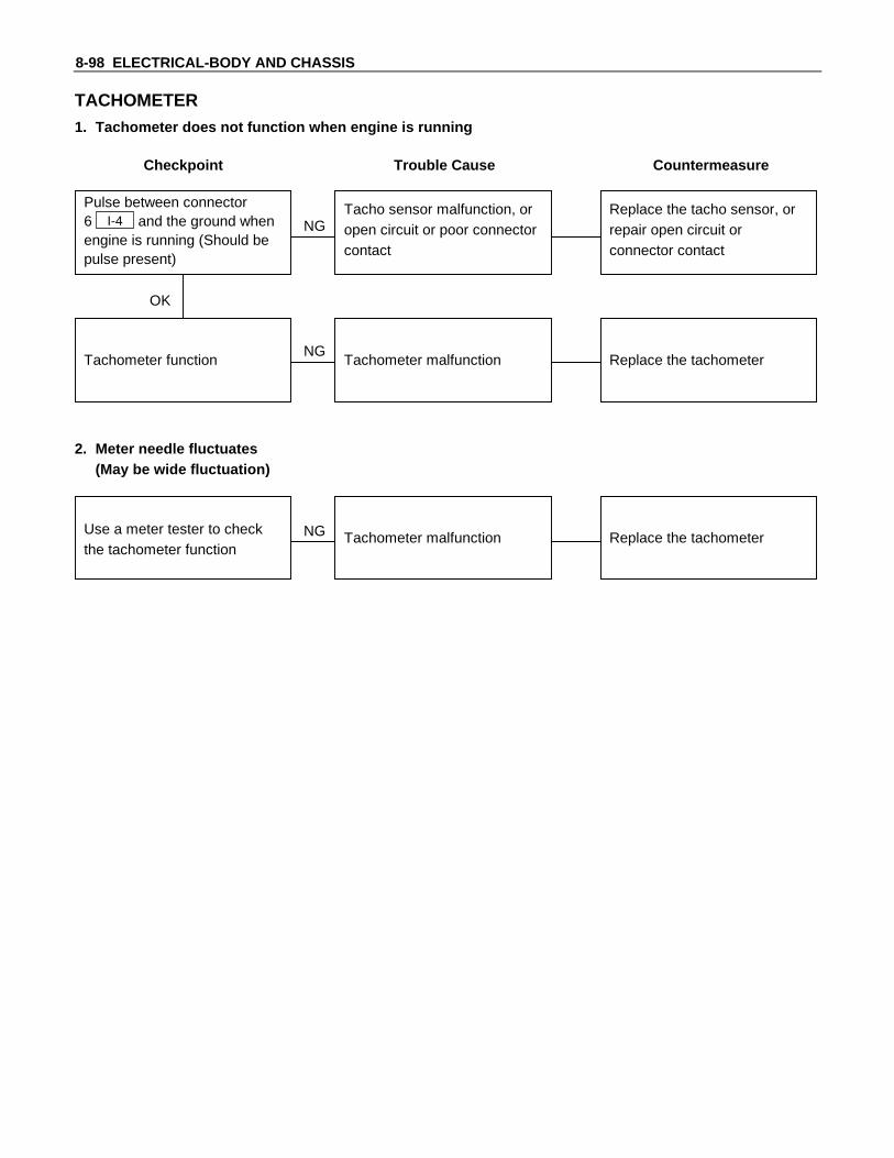
8-98 ELECTRICAL-BODY AND CHASSIS
TACHOMETER1. Tachometer does not function when engine is running
Checkpoint Trouble Cause Countermeasure
Replace the tacho sensor, orrepair open circuit orconnector contact
Tacho sensor malfunction, oropen circuit or poor connectorcontact
NG
Replace the tachometerTachometer function Tachometer malfunctionNG
OK
Pulse between connector6 I-4 and the ground whenengine is running (Should bepulse present)
2. Meter needle fluctuates(May be wide fluctuation)
Replace the tachometerTachometer malfunctionNGUse a meter tester to checkthe tachometer function

ELECTRICAL-BODY AND CHASSIS 8-99
TEMPERATURE GAUGE AND THERMO UNIT1. No temperature indicates at all
Checkpoint Trouble Cause Countermeasure
Replace the thermo unitThermo unit malfunctionNG
Replace the temperaturegauge
Gauge function1. Disconnect the unit
connector then connect3.4W bulb to wire harnessside with ground
2. Check indicating pointwhen starter SW. is ONposition (Temperatureshould indicate)
Gauge malfunction
Repair open circuit orconnector contact
Continuity between 1 TE-10
and 3 I-4Open circuit or poor connectorcontact
NG
NG
OK
OK
Thermo unit continuitybetween connector 1 TE-10
and the ground
2. Temperature gauge incorrect readings in all ranges
Replace the thermo unitThermo unit malfunctionNG
Thermo unit resistancebetween connector 1 TE-10
and the ground whendisconnecting the connector(Specified resistance shouldindicate)

8-100 ELECTRICAL-BODY AND CHASSIS
FUEL GAUGE AND FUEL TANK UNIT1. No fuel level indicates at all
Checkpoint Trouble Cause Countermeasure
Replace the tank unitOpen circuit inside the tankunit
NG
Thermo unit malfunction
Replace the fuel gauge
Fuel gauge function1. Disconnect the tank unit
connector then connect3.4W bulb to wire harnessside
2. Check indicating pointwhen starter SW. is ONposition (Fuel level shouldindicate)
Gauge malfunction
Repair open circuit orconnector contact
Continuity betweenconnectors 4 I-4 and2 CH-1
Open circuit or poor connectorcontact
NG
NG
OK
OK
Tank unit continuity betweenconnector 2 CH-1 and ground
2. Fuel gauge gives incorrect readings in all ranges
Replace the tank unitTank unit malfunctionNG
Tank unit resistance positionwith the float at checkingpoints (Specified resistanceshould indicate)

ELECTRICAL-BODY AND CHASSIS 8-101
WARNING AND INCIDATOR LIGHT1. When the parking brake lever is pulled, the indicator light does not light up
Checkpoint Trouble Cause Countermeasure
Replace or reinstall the bulbBulb burned out or loosecontact
NG
Adjust or replace the parkingbrake SW.
Parking brake SW. installationposition and function
Incorrect SW. adjustment orpoor SW. point contact
Repair open circuit orconnector contact
Continuity between theparking brake SW. connectorB-20 and 4 I-3
Open circuit or poor connectorcontact
NG
NG
OK
OK
Brake indicator light bulbcontinuity
Replace the parking brakeSW.
Continuity between theparking brake SW. connectorB-20 and the ground when
the parking brake is operated
Parking brake SW.malfunction
NG
OK
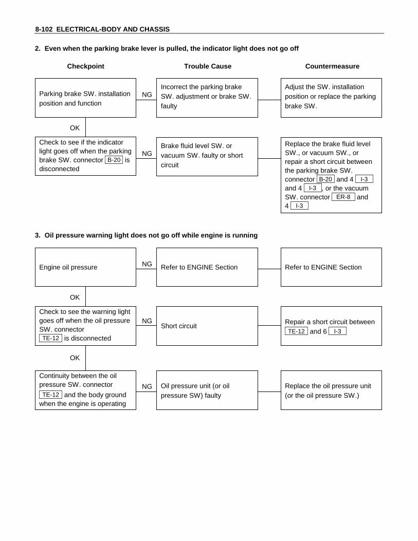
8-102 ELECTRICAL-BODY AND CHASSIS
2. Even when the parking brake lever is pulled, the indicator light does not go off
Checkpoint Trouble Cause Countermeasure
Adjust the SW. installationposition or replace the parkingbrake SW.
Incorrect the parking brakeSW. adjustment or brake SW.faulty
NG
Thermo unit malfunction
Replace the brake fluid levelSW., or vacuum SW., orrepair a short circuit betweenthe parking brake SW.connector B-20 and 4 I-3
and 4 I-3 , or the vacuumSW. connector ER-8 and4 I-3
Check to see if the indicatorlight goes off when the parkingbrake SW. connector B-20 isdisconnected
Brake fluid level SW. orvacuum SW. faulty or shortcircuit
NG
OK
Parking brake SW. installationposition and function
3. Oil pressure warning light does not go off while engine is running
Refer to ENGINE SectionRefer to ENGINE SectionNG
Thermo unit malfunction
Repair a short circuit betweenTE-12 and 6 I-3
Check to see the warning lightgoes off when the oil pressureSW. connectorTE-12 is disconnected
Short circuit
Replace the oil pressure unit(or the oil pressure SW.)
Continuity between the oilpressure SW. connector
TE-12 and the body groundwhen the engine is operating
Oil pressure unit (or oilpressure SW) faulty
NG
NG
OK
OK
Engine oil pressure
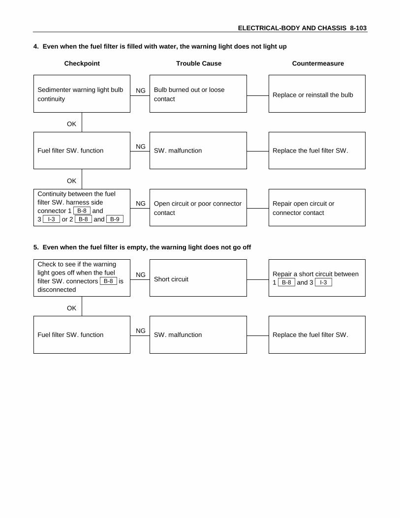
ELECTRICAL-BODY AND CHASSIS 8-103
4. Even when the fuel filter is filled with water, the warning light does not light up
Checkpoint Trouble Cause Countermeasure
Replace or reinstall the bulbBulb burned out or loosecontact
NG
Replace the fuel filter SW.Fuel filter SW. function SW. malfunctionNG
OK
Sedimenter warning light bulbcontinuity
Repair open circuit orconnector contact
Continuity between the fuelfilter SW. harness sideconnector 1 B-8 and3 I-3 or 2 B-8 and B-9
Open circuit or poor connectorcontact
NG
OK
5. Even when the fuel filter is empty, the warning light does not go off
Repair a short circuit between1 B-8 and 3 I-3Short circuit
NG
Replace the fuel filter SW.Fuel filter SW. function SW. malfunctionNG
OK
Check to see if the warninglight goes off when the fuelfilter SW. connectors B-8 isdisconnected

8-104 ELECTRICAL-BODY AND CHASSIS
REMOVAL AND INSTALLATION
METER ASSEMBLYRemoval1. Instrument Panel Driver Lower Cover
• Refer to the removal steps of “INSTRUMENT PANEL” inSection 10 “CAB”.
2. Lower Cluster Assembly• Refer to the removal steps of “INSTRUMENT PANEL” in
Section 10 “CAB”.3. Instrument Panel Cluster Assembly
• Refer to the removal steps of “INSTRUMENT PANEL” inSection 10 “CAB”
4. Meter Assembly• Remove four screws of the meter assembly.• Disconnect the meter connectors.
InstallationFollow the removal procedure in the reverse order to install themeter.Pay close attention to the important points mentioned in thefollowing paragraphs.
ConnectorBe absolutely sure that the meter connectors are securelyconnected.This will prevent a poor contact and an open circuit.
Wire HarnessDo not pinch the wire harness between the cluster and themeter hood during the meter assembly installation procedure.Wire damage will result.

ELECTRICAL-BODY AND CHASSIS 8-105
METERS AND GAUGESRemoval1. Meter Assembly
• Refer to “METER ASSEMBLY” removal steps in thissystem.
2. Meter Glass3. Meter Needless
• Pull out the needles of speedometer and tachometer.4. Meter Board
• Loosen four fixing screws.5. Meters and Gauges
InstallationTo Install, follow the removal steps in the reverse order.
WARNING LIGHT BULB, INDICATORLIGHT BULB AND ILLUMINATION LIGHTBULBRemovalTurn the bulb socket counterclockwise and pull the bulb out.
InstallationTo Install, follow the removal steps in the reverse order.
FUEL TANK UNITRemovalDismount the fuel tank first, then remove the fuel tank unit.1. Disconnect the fuel tank unit connector.2. Loosen the screws 1 .
3. Remove the fuel tank unit 2 from the fuel tank 3 .

8-106 ELECTRICAL-BODY AND CHASSIS
InstallationFollow the removal procedure in the reverse order to install thefuel tank unit.Pay close attention to the important points mentioned in thefollowing paragraphs.
Rubber SealBe absolutely sure that the fuel tank unit rubber seal iscorrectly seated.
ConnectorBe absolutely sure that the fuel tank unit connector is securelyconnected.This will prevent a poor contact and an open circuit.
VEHICLE SPEED SENSOR (INSTALLEDON THE TRANSMISSION)Removal1. Disconnect the connector.2. Remove the vehicle speed sensor body by rotating it.
InstallationTo Install, follow the removal steps in the reverse order, notingthe following point.Tighten the vehicle speed sensor to the specified torque.Vehicle Speed Sensor Tightening Torque N⋅m (kgf⋅m/lb⋅ft)
27.0 ± 2.5 (2.75 ± 0.25/19.9 ± 1.8)
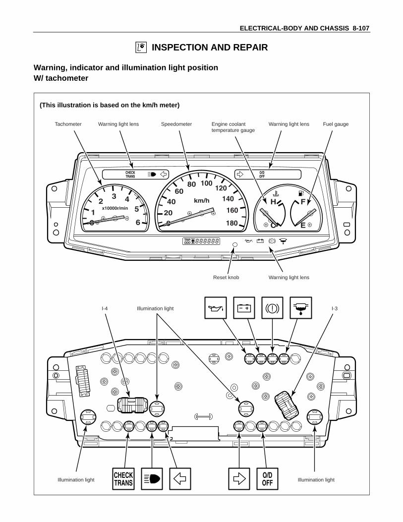
ELECTRICAL-BODY AND CHASSIS 8-107
INSPECTION AND REPAIR
Warning, indicator and illumination light positionW/ tachometer
(This illustration is based on the km/h meter)
Tachometer Speedometer Engine coolanttemperature gauge
Fuel gaugeWarning light lens Warning light lens
Warning light lensReset knob
Illumination light Illumination light
Illumination lightI-4 I-3

8-108 ELECTRICAL-BODY AND CHASSIS
Meter connector pin arrangementW/ Tachometer
5 46 2 13
8 7913 12 11 1014
5 47 2 13
9 81014 13 12 1116
6
15
I-3I-4
Connector
Ter-No.
minal No.I-3
1 -2 -3 Sedimenter warning light (−)4 Brake warning light (−)5 Charge warning light (−)6 Oil pressure warning light (−)7 -8 -9 OD/OFF indicator (−)
10 Fuse (C-1) Meter11 -12 Turn signal indicator light (RH) (+)13 Illumination light (+)14 Interface (−)
Connector
Ter-No.
minal No.I-4
1 Illumination light (+)2 Fuse (E-9) Audio, Clock3 Interface (−)4 Interface (−)5 Interface (−)6 Interface (−)7 Interface (−)8 Ground9 Turn signal indicator light (LH) (+)
10 High-beam indicator light (+)11 Ground12 -13 Check Trans (−)14 -15 -16 Check Trans (+)
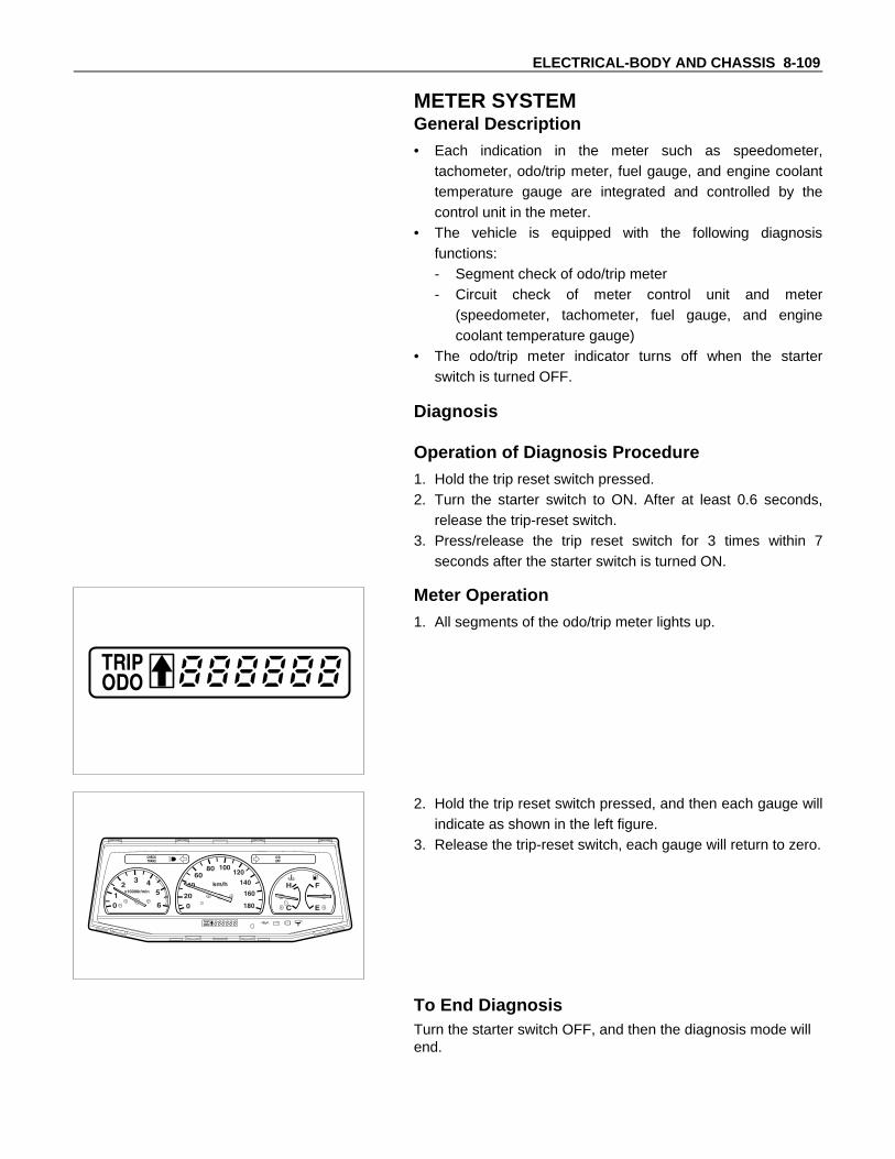
ELECTRICAL-BODY AND CHASSIS 8-109
METER SYSTEMGeneral Description• Each indication in the meter such as speedometer,
tachometer, odo/trip meter, fuel gauge, and engine coolanttemperature gauge are integrated and controlled by thecontrol unit in the meter.
• The vehicle is equipped with the following diagnosisfunctions:- Segment check of odo/trip meter- Circuit check of meter control unit and meter
(speedometer, tachometer, fuel gauge, and enginecoolant temperature gauge)
• The odo/trip meter indicator turns off when the starterswitch is turned OFF.
Diagnosis
Operation of Diagnosis Procedure1. Hold the trip reset switch pressed.2. Turn the starter switch to ON. After at least 0.6 seconds,
release the trip-reset switch.3. Press/release the trip reset switch for 3 times within 7
seconds after the starter switch is turned ON.
Meter Operation1. All segments of the odo/trip meter lights up.
2. Hold the trip reset switch pressed, and then each gauge willindicate as shown in the left figure.
3. Release the trip-reset switch, each gauge will return to zero.
To End DiagnosisTurn the starter switch OFF, and then the diagnosis mode willend.

8-110 ELECTRICAL-BODY AND CHASSIS
DIAGNOSIS FLOW CHART
Meter malfunction
Power circuit malfunction
Warning lights in themeter light up
NG
NG
NG
NG
OK
OK
OK
OK
Go to diagnosis 2Repair the NG part and carry outthe diagnosis function again
Go to diagnosis 1Connector contact and screw ofmeter which indicated malfunction
Segment display and gauge indication
Diagnosis functionoperation
Diagnosis 1Phenomenon Possible Malfunction
One malfunction in meter
1. Sensor circuit of malfunction indicated in meter(speedometer, tachometer, fuel gauge, and enginecoolant temperature gauge)
2. Meter
More than twomalfunction in meter
Odo/trip meter malfunction1. Vehicle speed sensor input signal2. Odo/trip meter3. Meter
Others 1. Meter
Diagnosis 2Phenomenon Possible Malfunction
Odo/trip meter indicates malfunction Meter
Meter indicates more than two
NG Malfunction indicated meter
OK Meter
Either speedometer, tachometer, fuelgauge or engine coolant temperaturegauge indicates malfunction
Inspect resistance ofmalfunction indicated meter

ELECTRICAL-BODY AND CHASSIS 8-111
TROUBLESHOOTING
Checkpoint Quick Reference Chart1. Speedometer
Checkpoint
Malfunctioning ConditionSpeedometer
Vehicle speedsensor
Cable harness
1-1 Speedometer and odometer doesnot operate
(3)
(1)
(2)
1-2 Speedometer does not operate(odometer is okay)
(1)
1-3 Odometer does not operate(speedometer is okay)
(1)
1-4 Speedometer needle fluctuates(may be wide fluctuated)
(3)
(1)
(2)
1-5 Errors in the speedometer reading islarge
(3)
(1)
(2)
Note: Numbers in the ( ) indicates the inspecting orders.
2. Tachometer
Checkpoint
Malfunctioning ConditionTachometer Tacho sensor Cable harness
2-1 Tachometer does not operate
(3)
(1)
(2)
2-2 Tachometer needle fluctuates( may be wide fluctuated)
(3)
(1)
(2)
2-3 Errors in the tachometer reading islarge
(3)
(1)
(2)
Note: Numbers in the ( ) indicates the inspecting orders.
3. Temperature gauge
Checkpoint
Malfunctioning Condition
Meterassembly
Temperaturegauge
Thermounit
Thermo-stat
Cableharness
3-1 Temperature gauge needle does notfluctuate
(3)
(4)
(2)
(1)
3-2 Indicates lower (or higher) enginecoolant temperature
(4)
(5)
(3)
(1)
(2)
3-3 Needle swings past the “H”(or rises to “H”)
(3)
(4)
(1)
(2)
Note: Numbers in the ( ) indicates the inspecting orders.
4. Fuel gauge
Checkpoint
Malfunctioning Condition
Meterassembly
Fuel gaugeFuel tank
unitCable
harness
4-1 Fuel gauge needle does notfluctuate
(3)
(4)
(2)
(1)
4-2 Needle does not reach “F” evenafter fully refueled
(3)
(4)
(2)
(1)
4-3 Needle swings past the “F” (or risesto “F”) when fuel tank is not full
(3)
(4)
(2)
(1)
Note: Numbers in the ( ) indicates the inspecting order

8-112 ELECTRICAL-BODY AND CHASSIS
5 Warning/Indicator light
Checkpoint
Malfunctioning Condition
Light
bulb
Parking
brake SW
Oil pressure
SW
Fuel tank
unit
Water
sedimenter SW
Cable
harness
5-1 When the parking lever is pulled, theindicator light does not light up
(1)
(2)
(3)
5-2 Even when the parking lever is fullyreturned, the indicator light does notgo off
(1)
(2)
5-3 Oil pressure warning light does notgo off while engine is running
(2)
(1)
5-4 When water in water sedimenterpassed the water draining line, theindicator light does not light up
(1)
(2)
(3)
5-5 When there is no water in watersedimenter, the indicator lights up
(2)
(1)
Note: Numbers in the ( ) indicates the inspecting order
1. Speedometer1-1. Speedometer and odometer does not operate
Replace the speedometer
OK
Circuit between vehicle speed sensor and meterCircuit between fuse C-1 (10A: 12V) and ground
Vehicle speed sensor output
NG
OK NG
Replace vehicle speed sensor
Repair open circuit or connector contact
1-2. Speedometer does not operate
Replace the meter
1-3. Odometer does not operate (Speedometer is okay)
Replace the meter

ELECTRICAL-BODY AND CHASSIS 8-113
1-4. Speedometer needle fluctuates (may be wide fluctuated)
Replace the speedometer
OK
Vehicle speed sensor output
NG
Replace the vehicle speed sensor orrepair open circuit or connector contact
Waveform by oscilloscope jumps erratically
1-5. Errors in the speedometer reading is large
Replace the speedometer
OK
Speedometer output
NG
Replace the vehicle speed sensor or repairharness defect or connector contact
Waveform cycle by oscilloscope is abnormal

8-114 ELECTRICAL-BODY AND CHASSIS
Inspection of a waveform by oscilloscope1. Connect a resistance of 1.3 to 5kΩ (1.4W or more) between the harness side connectors 10 I-3 and
7 I-4 of the meter.
2 31 5 6413 14128 9 10 117
3 41 6 7515 161410 11 12 138
29
I-4 I-3
2. Install a speedometer tester.3. Turn on the starter switch.4. Check the waveform at the time when the vehicle speed is at 60 km/h.
2. Tachometer2-1 Tachometer does not operate
Replace the tachometer
OK
Pulse input
NG
Replace the tacho sensor or repairharness defect or connector contact
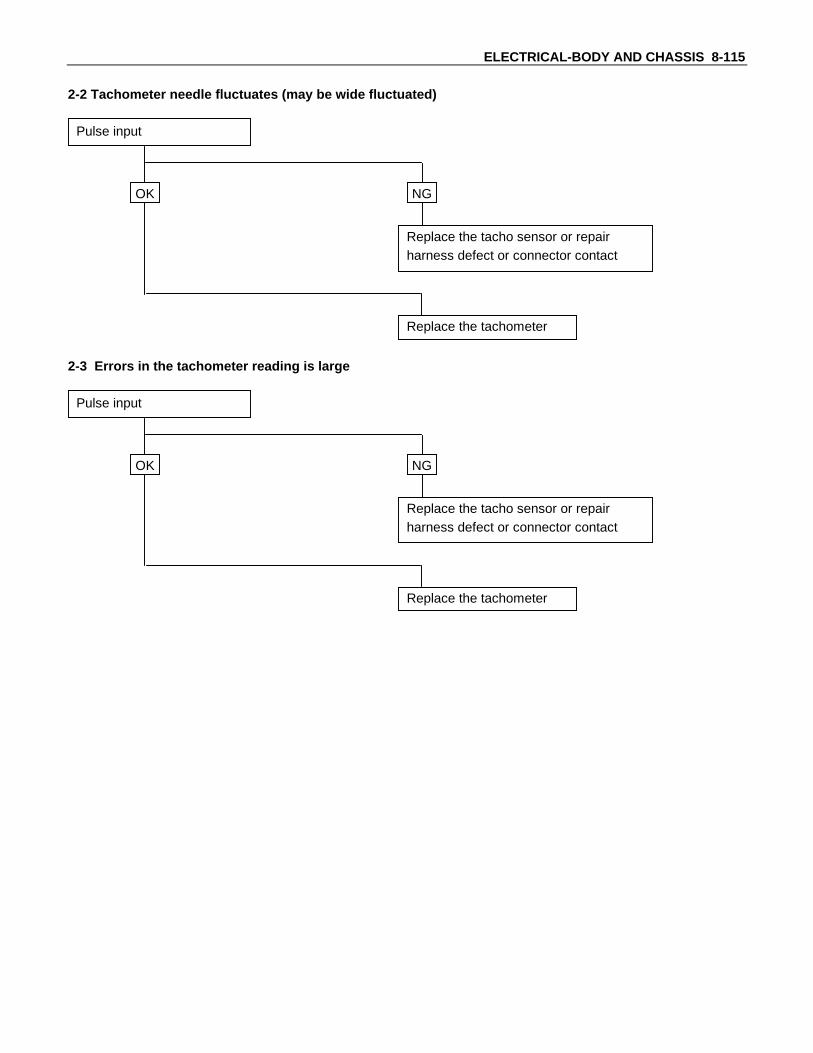
ELECTRICAL-BODY AND CHASSIS 8-115
2-2 Tachometer needle fluctuates (may be wide fluctuated)
Replace the tachometer
OK
Pulse input
NG
Replace the tacho sensor or repairharness defect or connector contact
2-3 Errors in the tachometer reading is large
Replace the tachometer
OK
Pulse input
NG
Replace the tacho sensor or repairharness defect or connector contact
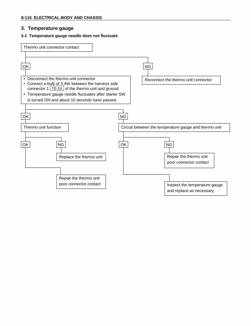
8-116 ELECTRICAL-BODY AND CHASSIS
3. Temperature gauge3-1 Temperature gauge needle does not fluctuate
OK
OK
OK
Thermo unit function
Thermo unit connector contact
NG
NG
Reconnect the thermo unit connector• Disconnect the thermo unit connector• Connect a bulb of 3.4W between the harness side
connector 1 TE-10 of the thermo unit and ground• Temperature gauge needle fluctuates after starter SW
is turned ON and about 10 seconds have passed.
NG
Circuit between the temperature gauge and thermo unit
Replace the thermo unit
Repair the thermo unitpoor connector contact
OK NG
Repair the thermo unitpoor connector contact
Inspect the temperature gaugeand replace as necessary

ELECTRICAL-BODY AND CHASSIS 8-117
3-2 Indicates lower (or higher) engine coolant temperature
OK
OK
OK
Thermo unit function
Thermostat operation
NG
NG
Replace the thermostat• Turn the starter SW ON.• There is no changing in the temperature gauge
indication, when the thermo unit connector 1 TE-10 isconnected/disconnected a few times
Repair the poor connector contact
Inspect the temperature gauge and replaceas necessary
NG
Replace the thermo unit

8-118 ELECTRICAL-BODY AND CHASSIS
3-3 Needle swings past the “H” (or rises to “H”)
OK
OK
OK
Meter ground connection
Circuit between the thermo unit and temperature gauge
NG
NG
Replace the thermo unit
• Disconnect the thermo unit connector• Needle indicates the “H” side when the starter SW is
turned on
Repair the open circuit in the circuit
Inspect the temperature gauge and replaceas necessary
NG
Replace the meter
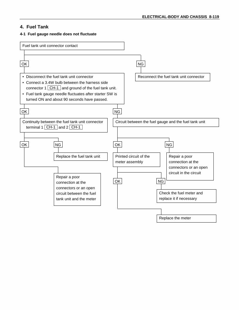
ELECTRICAL-BODY AND CHASSIS 8-119
4. Fuel Tank4-1 Fuel gauge needle does not fluctuate
OK
OK
OK
Continuity between the fuel tank unit connectorterminal 1 CH-1 and 2 CH-1
Fuel tank unit connector contact
NG
NG
Reconnect the fuel tank unit connector• Disconnect the fuel tank unit connector
• Connect a 3.4W bulb between the harness sideconnector 1 CH-1 and ground of the fuel tank unit.
• Fuel tank gauge needle fluctuates after starter SW isturned ON and about 90 seconds have passed.
NG
Circuit between the fuel gauge and the fuel tank unit
Replace the fuel tank unit
Repair a poorconnection at theconnectors or an opencircuit between the fueltank unit and the meter
OK NG
Repair a poorconnection at theconnectors or an opencircuit in the circuit
Check the fuel meter andreplace it if necessary
Printed circuit of themeter assembly
Replace the meter
OK NG
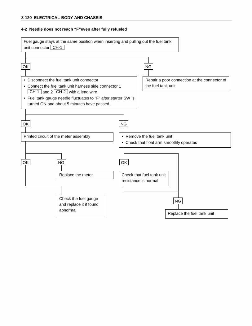
8-120 ELECTRICAL-BODY AND CHASSIS
4-2 Needle does not reach “F”even after fully refueled
OK
OK
OK
Printed circuit of the meter assembly
Fuel gauge stays at the same position when inserting and pulling out the fuel tank
unit connector CH-1
NG
NG
Repair a poor connection at the connector ofthe fuel tank unit
• Disconnect the fuel tank unit connector
• Connect the fuel tank unit harness side connector 1CH-1 and 2 CH-2 with a lead wire
• Fuel tank gauge needle fluctuates to "F" after starter SW isturned ON and about 5 minutes have passed.
NG
• Remove the fuel tank unit
• Check that float arm smoothly operates
Replace the meter
Check the fuel gaugeand replace it if foundabnormal
OK
Replace the fuel tank unit
Check that fuel tank unitresistance is normal
NG

ELECTRICAL-BODY AND CHASSIS 8-121
4-3 Needle swings past the “F” (or rises to “F”) when fuel tank is not full
Meter groundconnection
OK
OK
• Disconnect the fuel tank unit connector• Needle indicates the “F” side when the
starter SW is turned ON
NG
NG
NG
Circuit between the fuel tank unit andfuel gauge is not shorted to ground
Inspect resistance at the fueltank unit point “E” and “F”
• Remove the fuel tank unit• Front arm moves smoothly
Repair theshort circuit
OK NG
Replace the meter
OK
Inspect the fuel gaugeand replace asnecessary
Replace the fuel tank unit

8-122 ELECTRICAL-BODY AND CHASSIS
5. Warning and Indicator Light5-1 When the parking brake lever is pulled, the indicator light does not light up
Continuity between the SWconnector 1 B-20 and body whenthe parking brake is operated
OK
OK
• Disconnect the parking brake SW connector• Connect the harness side connector to ground• Indicator lights up when the starter SW is
turned ON
NG
NG
Parking brake SW installation
Continuity betweenparking brake SWconnector 1 B-20 and 4
I-3 (meter)
Indicator light bulb and socket contact
Adjust the installationposition
OK
Replace the bulb orrepair the loose contact
NG
Repair open circuit orconnector contact
NG
NG
Repair or replace the parking brake SW
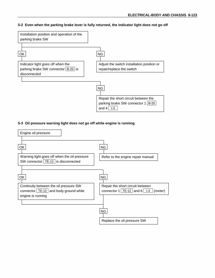
ELECTRICAL-BODY AND CHASSIS 8-123
5-2 Even when the parking brake lever is fully returned, the indicator light does not go off
OK
Installation position and operation of theparking brake SW
Indicator light goes off when theparking brake SW connector B-20 isdisconnected
NG
Adjust the switch installation position orrepair/replace the switch
NG
Repair the short circuit between theparking brake SW connector 1 B-20
and 4 I-3
5-3 Oil pressure warning light does not go off while engine is running
OK
OK
Engine oil pressure
Continuity between the oil pressure SWconnector TE-12 and body ground whileengine is running
Warning light goes off when the oil pressureSW connector TE-12 is disconnected
NG
Replace the oil pressure SW
Refer to the engine repair manual
NG
NG
Repair the short circuit betweenconnector 1 TE-12 and 6 I-3 (meter)

8-124 ELECTRICAL-BODY AND CHASSIS
5-4 When water in sedimenter passed the water draining line, the indicator light does not light up
OK
OK
Indicator light bulb and socket contact
NG
NG
Replace the bulb or repair a poor connection at thesocket
Water sedimenter SW
Replace the water sedimenter SW
Repair a poor connection at the connectors or an opencircuit in the circuit between the water sedimenter SWharness side connector B-8 (positive terminal) and 3
I-3
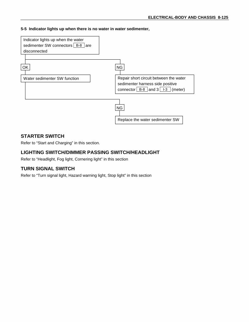
ELECTRICAL-BODY AND CHASSIS 8-125
5-5 Indicator lights up when there is no water in water sedimenter,
OK
Indicator lights up when the watersedimenter SW connectors B-8 aredisconnected
Water sedimenter SW function
NG
Repair short circuit between the watersedimenter harness side positiveconnector B-8 and 3 I-3 (meter)
NG
Replace the water sedimenter SW
STARTER SWITCHRefer to “Start and Charging” in this section.
LIGHTING SWITCH/DIMMER PASSING SWITCH/HEADLIGHTRefer to “Headlight, Fog light, Cornering light” in this section
TURN SIGNAL SWITCHRefer to “Turn signal light, Hazard warning light, Stop light” in this section

8-126 ELECTRICAL-BODY AND CHASSIS
SPEEDOMETER AND TACHOMETERSpeedometer On-Vehicle InspectionCheck the speedometer accuracy with a speedometer tester.Carefully follow the tester manufacturer’s instructions.
km/h meter km/h
Indication Permissible Range
20 17.5-22.540 37.5-42.560 57.5-62.580 77.5-82.5
100 97.6-103.4120 117.6-123.4140 137.6-143.4160 157.2-163.8
SIN
SIN
COS
COS
BATT
GND
IGN
Speedometer Off-Vehicle InspectionRemove the speedometer from the meter assembly andmeasure the resistance and the current consumption betweeneach terminal.Speedometer Resistance
Terminal symbol Resistance
COS + - COS - 222Ω ± 10%
SIN + - SIN - 268Ω ± 10%
Note: Use the analog type circuit tester (range: × 1k).
Speedometer Current Consumption
Terminal symbol Current consumption
IGN - GND+ -
16 − 36mA(when 12 ± 1V applied)
Note: 1. Use the analog type circuit tester.2. Since the current consumption fluctuates when the
source voltage varies, check to be sure that thevoltage applied is 12V ± 1V.

ELECTRICAL-BODY AND CHASSIS 8-127
Tachometer On-Vehicle Inspection1. Attach a tune-up tester to the engine.2. Start the engine.3. Compare the tachometer reading and the tester reading.
If the tachometer indication is outside the permissiblerange, the tachometer must be replaced.
4. Gradually increase and decrease the engine speed.Note the movement of the tachometer needle.If the needle movement is sluggish, the tachometer must bereplaced.
rpm
Indication Permissible Range
1,000 940-10602,000 1875-21253,000 2850-31504,000 3820-41805,000 4820-51806,000 5820-6180
SIN
SIN
COS
COS
Tachometer Off-Vehicle InspectionRemove the tachometer from the meter assembly andmeasure the resistance value and the current consumptionbetween each terminal.Tachometer Resistance
Terminal symbol Resistance
COS + - COS - 222Ω ± 10%
SIN + - SIN - 268Ω ± 10%
Note: Use the analog type circuit tester (range: × 1k).
TACHO SENSORInspectionMeasure the resistance between the tacho sensor connectorterminals.If not as specified, replace the tacho sensor.
Resistance: 1.36 - 1.86kΩ

8-128 ELECTRICAL-BODY AND CHASSIS
Removal1. Disconnect the tacho sensor connector.2. Remove the tacho sensor.
InstallationInstall in the reverse order of removal.
W/Tachometer
Engine coolant temperature gauge
TEMPERATURE GAUGE AND THERMOUNIT
Temperature Gauge On-Vehicle Inspection1. Disconnect the temperature gauge wire connector.2. Connect a 3.4 Watt test bulb 1 to the ground.
The gauge needle should move the middle part of thegauge.
GND
SIN
COS
Temperature Gauge
Temperature Gauge Off-Vehicle InspectionUse a circuit tester to measure the temperature gaugeresistance.Temperature Gauge Resistance
Terminal symbol Resistance
COS + - GND 222Ω ± 10%
SIN + - GND 268Ω ± 10%

ELECTRICAL-BODY AND CHASSIS 8-129
Thermo Unit InspectionThe thermo unit is thermistor type and must be inspectedunder the conditions as shown in the left chart.1. Put the deviation of the galvanometer to 0 using the variable
resistor, switch the thermo unit off and then measure theresistance of the resistor through the bridge.Confirm that the resistance is continuously variable in anyother points than those shown in the following table.
2. Dip the thermo unit into 80 - 90°C (176 - 194°F) water andconfirm that there is no bubble continuously coming out ofinside of the unit.Replace the unit when the result of inspection is foundabnormal.
INDICATIONSCALE (°C)
RESISTANCE(Ω)
ANGLE(°)
INDICATIONERROR (°)
120 23.0 71 ± 4.0
110 31.3 38 ± 4.0
65 130.0 38 ± 4.0
50 252.0 0 ± 4.0
WATER SEDIMENTER SWITCHInspection1. Verify that there is continuity between the switch connector
terminals when the water float of the sedimenter is abovethe water draining line.
2. Turn the starter switch to ON.3. Disconnect the water sedimenter connector. Verify that the
warning light lights on when the harness side connectorterminals are connected.If not as specified, replace the switch or repair poorconnection or open circuit.

8-130 ELECTRICAL-BODY AND CHASSIS
W/Tachometer
Fuel gauge
FUEL GAUGE AND TANK UNIT
Fuel gauge On-Vehicle Inspection1. Disconnect the fuel gauge wire connector.2. Connect a 3.4 Watt test bulb 1 to the ground.
The gauge needle should more the middle part of thegauge.
GND
SIN
COS Fuel Gauge
Fuel Gauge Off-Vehicle InspectionUse a circuit tester to measure the fuel gauge resistance.Fuel Gauge Resistance
Terminal symbol Resistance
COS + - GND 222Ω ± 10%
SIN + - GND 268Ω ± 10%
Fuel Tank Unit InspectionMeasure the fuel tank unit resistance between the connectorterminals 2 CH-1 and 1 CH-1 while shifting the float from “E”to “F” point.
Fuel Tank Resistance
INDICATIONSCALE (°C)
RESISTANCE(Ω)
ANGLE(°)
INDICATIONERROR (°)
F(B) 23.5 80 +4.6−0
½(A) 45.0 40 ± 3.4
E(C) 102.5 0 +0−3.4
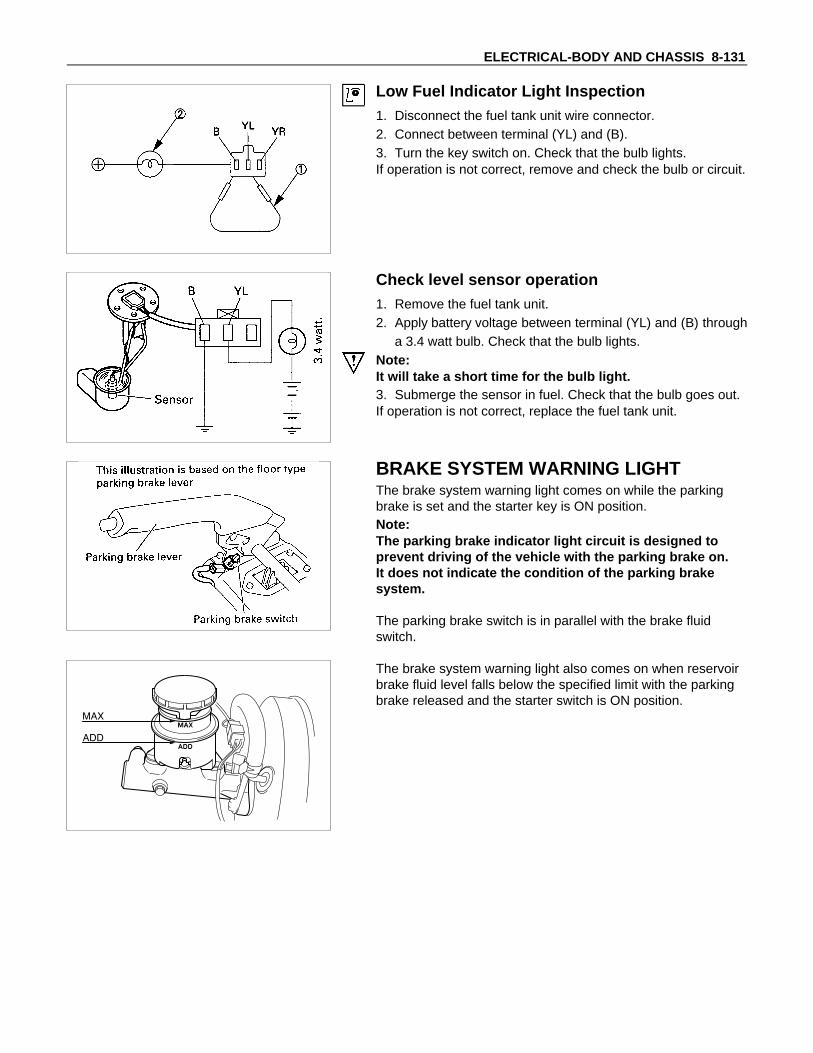
ELECTRICAL-BODY AND CHASSIS 8-131
Low Fuel Indicator Light Inspection1. Disconnect the fuel tank unit wire connector.2. Connect between terminal (YL) and (B).3. Turn the key switch on. Check that the bulb lights.If operation is not correct, remove and check the bulb or circuit.
Check level sensor operation1. Remove the fuel tank unit.2. Apply battery voltage between terminal (YL) and (B) through
a 3.4 watt bulb. Check that the bulb lights.Note:It will take a short time for the bulb light.3. Submerge the sensor in fuel. Check that the bulb goes out.If operation is not correct, replace the fuel tank unit.
BRAKE SYSTEM WARNING LIGHTThe brake system warning light comes on while the parkingbrake is set and the starter key is ON position.Note:The parking brake indicator light circuit is designed toprevent driving of the vehicle with the parking brake on.It does not indicate the condition of the parking brakesystem.
The parking brake switch is in parallel with the brake fluidswitch.
The brake system warning light also comes on when reservoirbrake fluid level falls below the specified limit with the parkingbrake released and the starter switch is ON position.

8-132 ELECTRICAL-BODY AND CHASSIS
PARKING BRAKE INDICATOR LIGHTThe parking brake indicator light is parallel with the parkingbrake switch, which is installed to the parking brake leverbracket. It lights up when the parking brake lever is pulled andgoes off when the lever is fully returned.Note:The circuit of the parking brake indicator light is designedto prevent driving of the vehicle with the parking brake on.It does not indicate the condition of the parking brakesystem.
Parking Brake Indicator Light Circuit Inspection1. Disconnect the parking brake switch connector.2. Connect the harness side connector to ground.3. Turn the starter switch to ON and verify that the indicator
light turns on. If the indicator light does not turn on, inspectthe bulb or harness.
PARKING BRAKE SWITCHInspection1. Disconnect the parking brake switch connector.2. Connect a circuit tester between the switch terminal and
ground and inspect continuity.
When the parking brake lever is pulled = ContinuityWhen the parking brake lever is fully returned = Nocontinuity
If not as specified, replace the parking brake switch.
Removal1. Parking brake switch
• Disconnect the parking brake switch.• Remove the fixing screw.
InstallationInstall in the reverse order of removal.

ELECTRICAL-BODY AND CHASSIS 8-133
VEHICLE SPEED SENSOR (INSTALLEDON THE TRANSMISSION)The speed sensor is installed on the rear portion of thetransmission.The number of pulses generated is four pulses per one rotationof the pinion shaft.
Vehicle Speed Sensor Inspection1. Connect the vehicle speed sensor connector 1 TE-1 to the
battery (+) terminal and 2 TE-1 to the (-) terminal.2. Connect a resistance of 1.3K ohm to 5K ohm (1/4 W or
more) between connectors 1 TE-1 and 3 TE-1 .
CAUTION:Be extremely careful not to connect the battery (+) terminalto the connector 3 TE-1 .This may damage the vehicle speed sensor.
3. Rotate the shaft of the vehicle speed sensor slowly andmeasure the voltage at the both ends with a digital tester.
The voltage, with one rotation of shaft fluctuates four times inthe following range: 10 to 14V - 2V or less.
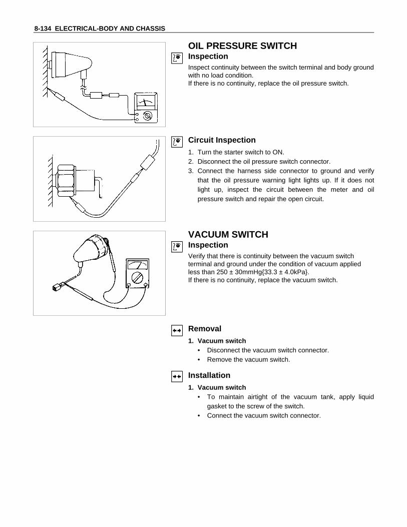
8-134 ELECTRICAL-BODY AND CHASSIS
OIL PRESSURE SWITCHInspectionInspect continuity between the switch terminal and body groundwith no load condition.If there is no continuity, replace the oil pressure switch.
Circuit Inspection1. Turn the starter switch to ON.2. Disconnect the oil pressure switch connector.3. Connect the harness side connector to ground and verify
that the oil pressure warning light lights up. If it does notlight up, inspect the circuit between the meter and oilpressure switch and repair the open circuit.
VACUUM SWITCHInspectionVerify that there is continuity between the vacuum switchterminal and ground under the condition of vacuum appliedless than 250 ± 30mmHg33.3 ± 4.0kPa.If there is no continuity, replace the vacuum switch.
Removal1. Vacuum switch
• Disconnect the vacuum switch connector.• Remove the vacuum switch.
Installation1. Vacuum switch
• To maintain airtight of the vacuum tank, apply liquidgasket to the screw of the switch.
• Connect the vacuum switch connector.
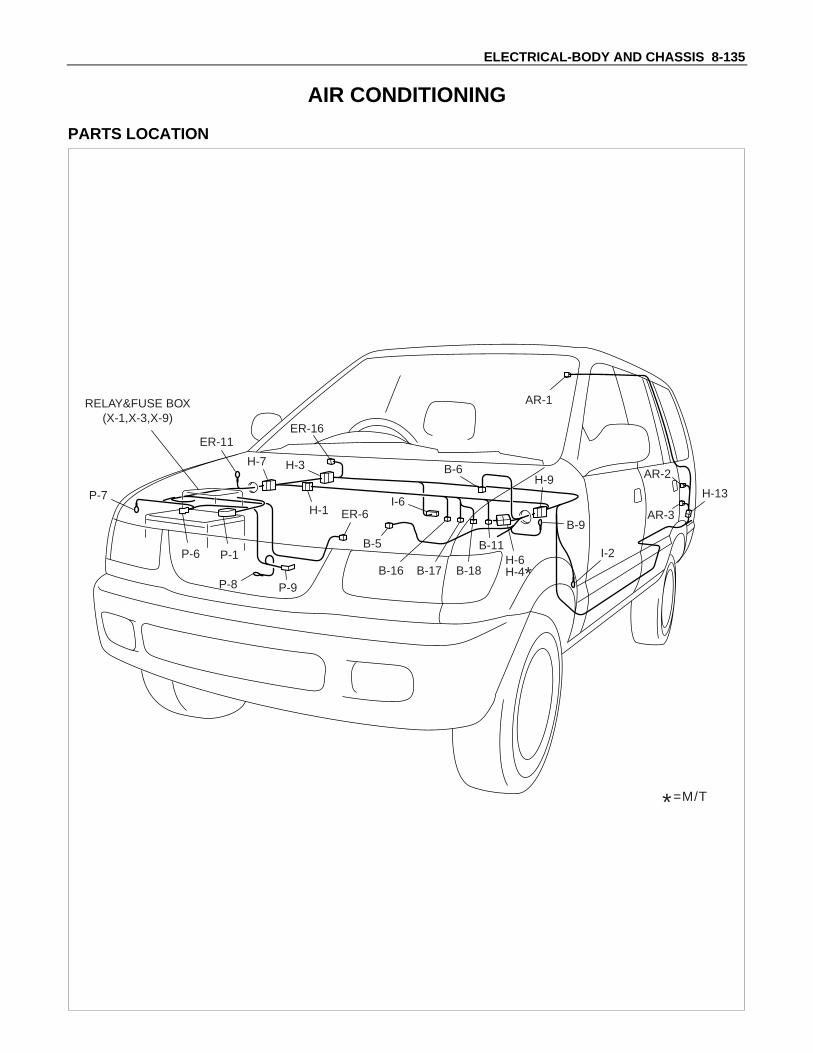
ELECTRICAL-BODY AND CHASSIS 8-135
AIR CONDITIONING
PARTS LOCATION
ER-11
P-7
P-8 P-9
H-3H-7
I-6
I-2
B-9
B-11
B-18B-17B-16
B-6
B-5
ER-6
AR-2
AR-1
AR-3
H-13
RELAY&FUSE BOX(X-1,X-3,X-9)
H-1
ER-16
H-9
P-1P-6
*=M/T
H-6H-4*

8-136 ELECTRICAL-BODY AND CHASSIS
CIRCUIT DIAGRAM
I-61
I-62
P-8
P-6BATTP-1
P-9 P-7
P-7 : EARTH ; BODYP-8 : EARTH ; FRAMEP-9 : EARTH ; ENGINE
30B
/Y
9B/Y
3W/B
3B/Y
(M/T
)
(A/T
)
0.85
R/B
0.85
R/B
0.5L
G/R
1.25
L/O
2L/B
0.5L
G/Y
0.5LG
0.5B
0.5G
/R
2L/W
2L/B
0.85
B
0.5L
G/R
2B
2L/B
0.85
B
5B/Y
MAINEB-360A
8B/R
IGNEB-240A
B
ACCIGST
SW ;STARTER
ER-163
B-16
2
I-6
6
I-6
7
I-6
3
I-6
4
ER-16
1
3W
X-13
I-65 H-7
15
I-68
X-11
X-12
X-15
X-14
B-161
3L/R 0.5BR
2L/R
RELAY ; A/C
B-9
ER-11
EARTH ; E/R (LH)
EARTH ; E/R (RH)
I-2EARTH ; BODY (LH) 2B
0.85B
2B
0.85B
2B
0.85B
0.85B
TU
RN
,BA
CK
C-5
15A
TU
RN
,BA
CK
UP
LA
MP
FU
SE
E-1
1(T
AIL
.LIG
HT
)
H-6
4
H-1
19
H-4
10
H-3
6
B-16
3 H-721
H-79
H-913
H-914
H-1
21
RR COOLERE-1420A
A/CE-1210A
FT COOLERE-1320A
BLO
WE
R(F
RT
)R
ES
ISTO
R(F
RT
)B-17
2
B-17
1
M
OFF LO Me
FAN SW (FRT) VAR.VOL.
BEZELILLUMI.
HI

ELECTRICAL-BODY AND CHASSIS 8-137
CIRCUIT DIAGRAMT
HE
RM
ISTO
R
RE
SIS
TOR
(RR
)
0.5B
0.5LG/W
A/C AMP.
0.5G/W
0.5B/R
0.5G/B
0.5B
R
0.5BR
0.5B
R
0.5B
R
2L/R 2L/R
0.5LG/B
AR-1
2
AR-1
1
B-11
1
B-18
8
H-1
15
H-1
14
B-185
B-61
B-186
H-116
B-181
B-182
AR-14
AR-13
B-184
B-62
AR-21
B-187
0.85B
2B
B-18
9
B-11
2
OFF LO Me
FAN SW (RR)
HI
H-122
H-131
0.85
L/W
2B2B
2L/B
1.25
L/O
2L/B
AR-2
2
AR-2
3
BLO
WE
R(R
R)
AR-3
1
AR-3
2
M
H-13
2
PRESS SW
X-3
5X
-33
RE
LAY
; A
/C C
OM
P
X-3
1X
-32
RE
LAY
; A
/C C
UT
M
AG
NE
TC
LUT
CH
VS
V ;
FIC
D
SW
; T
HE
RM
O(A
/C C
UT
)
1.25
BR
/Y (
A/T
)0.
5G (
A/T
)
1.25
BR
/Y (
M/T
)0.5B
/R
0.5O
0.5B
R/Y
ER
-6
1
X-9
X-9
1 3
4 5
X-9
X-9
B-5
1
TE
-9
1
H-1
11
H-5
12
0.5O

8-138 ELECTRICAL-BODY AND CHASSIS
POWER DOOR LOCK
PARTS LOCATION
H-9H-14
P-7
P-8 P-9
I-13FD-2
RD-7
H-10
FD-13
H-11I-1
H-3H-15
H-16 RD-8
BD-7
I-2
RELAY &FUSE BOX
P-6P-1
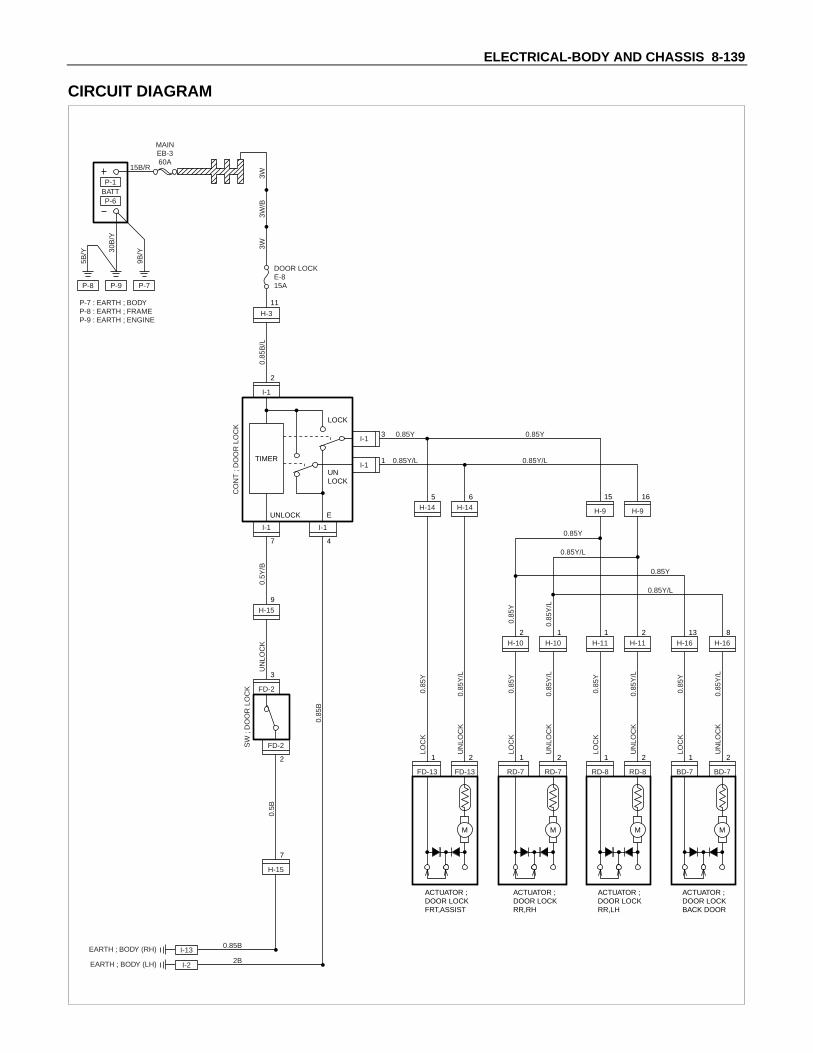
ELECTRICAL-BODY AND CHASSIS 8-139
CIRCUIT DIAGRAM
P-8
P-6BATTP-1
P-9 P-7
P-7 : EARTH ; BODYP-8 : EARTH ; FRAMEP-9 : EARTH ; ENGINE
30B
/Y
9B/Y
5B/Y
MAINEB-360A
15B/R
3W3W
CO
NT
; D
OO
R L
OC
K
SW
; D
OO
R L
OC
K
UN
LOC
K
LOC
K0.
85Y
0.85
Y/L
UN
LOC
K
0.5Y
/B
0.85
B
0.85
B/L
0.85Y
0.85Y
0.85Y/L
0.85Y/L
0.85Y
0.85Y
0.85Y/L
0.85Y/L
DOOR LOCKE-815A
3W/B
I-13
I-11
I-1
2
BD-7
1
BD-7
2
H-16
13
H-16
8
I-1
7
H-3
11
FD-2
3
H-15
7
H-15
9
FD-2
2
I-1
4
TIMER
UNLOCK
UNLOCK
LOCK
E
I-13EARTH ; BODY (RH) 0.85B
0.5B
I-2EARTH ; BODY (LH) 2B
M
ACTUATOR ;DOOR LOCKBACK DOOR
LOC
K0.
85Y
0.85
Y/L
UN
LOC
K
RD-8
1
RD-8
2
H-11
1
H-11
2
M
ACTUATOR ;DOOR LOCKRR,LH
LOC
K0.
85Y
0.85
Y/L
0.85
Y
0.85
Y/L
UN
LOC
K
RD-7
1
RD-7
2
M
ACTUATOR ;DOOR LOCKRR,RH
LOC
K0.
85Y
0.85
Y/L
UN
LOC
K
FD-13
1
FD-13
2
M
ACTUATOR ;DOOR LOCKFRT,ASSIST
H-9
15
H-9
16
H-14
6
H-14
5
H-10
2
H-10
1

8-140 ELECTRICAL-BODY AND CHASSIS
TROUBLESHOOTING
QUICK CHART FOR CHECK POINTS
Check Points FuseE-8 Door Lock Switch
Door Lock ActuatorCable
Trouble Mode(15A) (Driver’s side) Passenger’s
sideRR-RH RR-LH
Backdoor
Harness
1. All the doors do not lockand unlock
2. All the doors do not getlocked (or unlocked)
3. Driver’s side door does notget locked (or unlocked)
4. FRT passenger’s side doordoes not get locked (orunlocked)
5. RR door-RH does not getlocked (or unlocked)
6. RR door-LH does not getlocked (or unlocked)
7. Back door does not getlocked (or unlocked)
8. Door lock does not operatewhen operating from thedriver’s seat side

ELECTRICAL-BODY AND CHASSIS 8-141
1. All the doors do not lock and unlock
Checkpoint Trouble Cause Countermeasure
Reinstall or replace the fuseNo. E-8 (15A)
Poor fuse contact or blownNG
Repair grounding point( I-13 ) contact
Grounding point ( I-13 ) Poor grounding point contact
Repair open circuit orconnector contact
Voltage between the driver’sside door lock SW harnessside connector terminal2 I-1 and the ground(Should be battery voltagepresent)
Open circuit or poor connectorcontact
NG
NG
OK
OK
OK
Fuse No. E-8 (15A, Fuse box)
Repair open circuit orconnector contact
Open circuit or poor connectorcontact
NG
Replace the driver’s side doorlock SW.
Driver’s side door lock SW.function
SW. malfunctionNG
OK
Continuity between 4 I-1
and I-2
2. All the doors do not get locked (or unlocked)
Repair open circuit orconnector contact
Open circuit or poor connectorcontact
NG
Replace the driver’s side doorlock SW.
Driver’s side door lock SW.function
SW. malfunctionNG
OK
Continuity between the driver’sside door lock SW harnessside connector terminals1 I-1 and 3 I-1

8-142 ELECTRICAL-BODY AND CHASSIS
3. Driver’s side door does not get locked (or unlocked)
Checkpoint Trouble Cause Countermeasure
Replace the door lock SW.Door lock SW. function SW. malfunctionNG
4. FRT passenger’s side door does not get locked (or unlocked)
Replace the FRT passenger’sside door lock actuator
FRT passenger’s side doorlock actuator function
Actuator malfunctionNG
5. RR door-RH does not get locked (or unlocked)
Replace the RR door lockactuator-RH
RR door lock actuator-RHfunction
Actuator malfunctionNG
6. RR door-LH does not get locked (or unlocked)
Replace the RR door lockactuator-LH
RR door lock actuator-LHfunction
Actuator malfunctionNG
7. Back door does not get locked (or unlocked)
Replace the back door lockactuator
Back door lock actuatorfunction
Actuator malfunctionNG
8. Door lock does not operate when operated from the driver’s seat side
Repair grounding point( I-3 ) contact
Poor grounding point contactNG
Replace the door lock SW.
Continuity between the doorlock SW. side connector3 FD-2 and 2 FD-4 when theSW.
SW. malfunctionNG
OK
Grounding point ( I-3 )
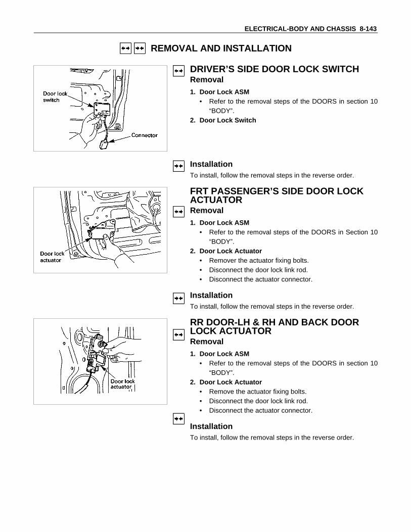
ELECTRICAL-BODY AND CHASSIS 8-143
REMOVAL AND INSTALLATION
DRIVER’S SIDE DOOR LOCK SWITCHRemoval1. Door Lock ASM
• Refer to the removal steps of the DOORS in section 10“BODY”.
2. Door Lock Switch
InstallationTo install, follow the removal steps in the reverse order.
FRT PASSENGER’S SIDE DOOR LOCKACTUATORRemoval1. Door Lock ASM
• Refer to the removal steps of the DOORS in Section 10“BODY”.
2. Door Lock Actuator• Remover the actuator fixing bolts.• Disconnect the door lock link rod.• Disconnect the actuator connector.
InstallationTo install, follow the removal steps in the reverse order.
RR DOOR-LH & RH AND BACK DOORLOCK ACTUATORRemoval1. Door Lock ASM
• Refer to the removal steps of the DOORS in section 10“BODY”.
2. Door Lock Actuator• Remove the actuator fixing bolts.• Disconnect the door lock link rod.• Disconnect the actuator connector.
InstallationTo install, follow the removal steps in the reverse order.

8-144 ELECTRICAL-BODY AND CHASSIS
INSPECTION AND REPAIR
Door Lock Switch (Driver’s Side)1. Harness Side Connector Circuit
Check voltage and continuity between the switch harnessside connector terminals as shown in the following table.
TerminalNo.
Wirecolor
Connecting to Check itemConnecting
terminalCheck condition Standard
Door lock SW Driver seat Lock No continuity
(Unlock) side door Unlock Continuity
4 B Ground Continuity 4-Ground - Continuity
3 YDoor lock
actuator (Lock)
(Resistance)
3-1 -Continuity
There is someresistance
1 Y/LDoor lockactuator(Unlock)
1-3 -Continuity
There is someresistance
2 B/LFuse
E-8 (15A)Voltage 2- Ground -
Battery voltage(Approx. 12V)
7-GroundY/B7

ELECTRICAL-BODY AND CHASSIS 8-145
2. Switch Side Connector CircuitRemove the switch connector, and check continuity andvoltage between the switch connector terminals.(Connect the (+) terminal of the battery to 2 I-1 and the(-) terminal to 4 I-1 .)
4 I-1 - 3 I-1 ..................Continuity4 I-1 - 1 I-1 ..................Continuity
3 I-1 ...........Current flow for approx. 1 second
1 I-1 ...........Current flow for approx. 1 second
3. Door Lock Operation TestAfter confirming that there is continuity between the switchharness side connector terminals 3 I-1 and 1 I-1 ,apply the battery voltage to each of the terminals to conductthe operation test.When the door lock will not operate, check the door lockactuator for any trouble.
Connecting terminals
3 (Y/L) 1 (Y)
+ - Unlock
- + Lock
Operation

8-146 ELECTRICAL-BODY AND CHASSIS
Switch side
FD-2
Door Lock Switch (Driver’s Side)1. Switch Side Connector Circuit
Check continuity between the switch connector terminals
Terminal No.
SW position1 2
Unlock
Front Passenger’s Side Door Lock Actuator1. Actuator Side Connector Circuit
Apply the battery voltage to the actuator connector terminalsto check the operation.When the door lock actuator is checked on the vehicle andthere is no continuity, and when the door lock actuator itselfis checked and no trouble is found, check the circuitbetween the door lock actuator and the driver seat sidepower window & door lock switch for any failure.
Connecting terminals
1 2
+ - Lock
- + Unlock
Operation
Rear Door Lock -LH & RH and Back DoorActuator1. Actuator Side Connector Circuit
Apply the battery voltage to the actuator connector terminalsto check the operation.When the door lock actuator is checked on the vehicle andthere is no continuity, and when the door lock actuator itselfis checked and no trouble is found, check the circuitbetween the door lock actuator and the driver seat sidepower window & door lock switch for any failure.
Connecting terminals
1 2
- + Lock
+ - Unlock
Operation

ELECTRICAL-BODY AND CHASSIS 8-147
POWER WINDOW
PARTS LOCATION
P-7
P-8 P-9
I-13
FD-1
FD-4
FD-15
RD-3(RD-1)
RD-6*1
RD-10*2
H-10
RD-4(RD-2)FD-12
(FD-11)RD-5*1
RD-9*2
H-11
ER-16
RELAY&FUSE BOX(X-4)
H-3H-15
H-7
ER-11
*1 = SWB
*2 = LWB
( ) = According to the model of the car,the connector number is changed.
H-9
H-14
H-1
P-1P-6

8-148 ELECTRICAL-BODY AND CHASSIS
CIRCUIT DIAGRAM
P-8
P-6BATTP-1
P-9 P-7
P-7 : EARTH ; BODYP-8 : EARTH ; FRAMEP-9 : EARTH ; ENGINE
30B
/Y
9B/Y
3W/B
5B/Y
MAINEB-360A
8B/R
IGNEB-240A
B
ACC
3B/Y
P/W MOTORFRT-DRIVER
3B/Y
IG
ST
ER-161
TURN,BACKC-515A
ER-163
SW ; STARTER
OFF
3W 2B/L
0.5B
2G/Y 2G/Y
0.85R/B
0.85
R/B
1.25
L/B
1.25
L/R
2B
0.85
R/B
CO
NT
RO
LLE
RO
NE
TO
UC
H
TU
RN
BA
CK
UP
LA
MP
P/W 30A
X-42
X-41
H-310
H-151
RELAY ;P/WINDOW
X-45
X-43
H-119
FD-1
7
H-32
UP DOWN
FD-1
15
FD-1
16
FD-1
2
ER-11EARTH ; E/R (RH)
I-13EARTH ; BODY (RH)
0.85B
2B
FD-42
FD-41M
UP DOWN
H-78
H-15
16

ELECTRICAL-BODY AND CHASSIS 8-149
CIRCUIT DIAGRAM
P/W MOTORFRT-ASSIST
1.25
G/Y
1.25
L/B
1.25
L/R
1.25
G/Y
1.25
G/R
1.25
R/Y
1.25G/Y
SW
; P
/WIN
DO
WF
RT-
AS
SIS
T
FD-128
UP DOWN
UP DOWN
FD-1
4
H-14
4
H-14
11
H-14
12
FD-12(FD-11)
7(4)
FD-12(FD-11)
5(2)
FD-1
3
FD-151
FD-152M
UP DOWN
FD-12(FD-11)
3(3)
FD-12(FD-11)
6(1)
FD-12(FD-11)
4(5)
P/W MOTORRR-RH
(SWB ONLY)
SW ; P/WINDOW FRT-DRIVER
∗ According to the vehicle model, the connector number is changed in parentheses.
1.25
G/Y
1.25
L/B
1.25
L/R
1.25
G/Y
1.25
R/B
1.25
G/O
1.25
R/L
1.25
G/B
1.25
R/B
1.25
G/O
SW
; P
/WIN
DO
WR
R-R
H
RD-38
UP DOWN
UP DOWN
FD-1
14
H-15
12
H-15
13
H-15
10
H-15
11
H-7
6
H-7
7
H-10
4
H-10
3
H-10
6
RD-3(RD-1)
7(4)
RD-3(RD-1)
5(2)
FD-1
13
RD-62
RD-61M
UP DOWN
P/W MOTORRR-RH
(LWB ONLY)
RD-102
RD-101M
UP DOWNP/W MOTOR
RR-LH(LWB ONLY)
RD-91
RD-92M
UP DOWN
RD-3(RD-1)
3(3)
RD-3(RD-1)
6(1)
RD-3(RD-1)
4(5)
P/W MOTORRR-LH
(SWB ONLY)
1.25
G/Y
1.25
L/B
1.25
L/R
1.25
G/Y
1.25
R/L
1.25
G/B
SW
; P
/WIN
DO
WR
R-L
H
RD-48
UP DOWN
UP DOWN
FD-1
10
RD-4(RD-2)
7(4)
RD-4(RD-2)
5(2)
FD-1
12
RD-51
RD-52M
UP DOWN
RD-4(RD-2)
3(3)
RD-4(RD-2)
6(1)
RD-4(RD-2)
4(5)
LOCK SW
H-15
14
H-15
15
H-9
18
H-9
19
H-11
4
H-11
6
H-11
3

8-150 ELECTRICAL-BODY AND CHASSIS
TROUBLE SHOOTING
QUICK CHART FOR CHECK POINTSCheck Points
Trouble ModePower Window Power Window
SwitchPower Window Motor
Driver’sSide
Passenger’sSide
RR-LH RR-RH Driver’sSide
Passenger’sSide
RR-LH RR-RH
All windows will not operate
Lock SW does not function
Driver’s Window:
Window does not operate
One-touch operation for“DOWN” movement will notoperate
Window operates in onlyone direction
Front window on passengerseat side:
Window does not operate
Window does not operatewhen operating the driver’sSW
Window does not operatewhen operating thepassenger’s SW
Window does operate inonly one direction whenoperating the driver’s SW
Window does operate inonly one direction whenoperating the passenger’sseat side SW
Rear window on left (or right)side:
Window on left (or right)side does not operate
Window does not operatewhen operating the driver’sSW
Window does operate inonly one direction whenoperating the driver’s SW
Window does operate inonly one direction whenoperating the RR-LH (orRH) side SW
CircuitBreaker
EB-5(30A)
CableHarness
Relay;Power
Window
FuseC-5
(15A)

ELECTRICAL-BODY AND CHASSIS 8-151
1. All windows do not operate
Checkpoint Trouble Cause Countermeasure
Reinstall or replace the fuseNo. C-5 (15A)
Poor fuse contact or blownNG
Replace the circuit breaker(30A)
Circuit breaker (30A, Fusebox) function
Circuit breaker 30A, Fuse boxmalfunction
Repair grounding points( I-13 and ER-11 ) contact
Grounding points ( I-13
ER-11 )Poor grounding point contact
NG
NG
OK
OK
OK
Fuse C-5 (15A, Fuse box)
Replace the power windowrelay
Power window relaymalfunction
NG
Repair an open circuit or apoor connection of theconnectors between circuitbreaker (30A, Fuse Box) and2 X-4
Voltage between the powerwindow relay harness sideconnector terminal 2 X-4
and the ground (Should bebattery voltage present)
Open circuit or poor connectorcontact
NG
OK
Power window relay function
OK
Repair an open circuit or apoor connection of theconnectors between 1 X-4
and 7 FD-1
Open circuit or poor connectorcontact
NGVoltage between 7 FD-1 andthe ground (Should be batteryvoltage present)
OK
Repair an open circuit or apoor connection of theconnectors between 2 RD-1
and ER-11 , or 3 X-4 andER-11
Open circuit or poor connectorcontact
NG
Continued on the next page
Voltage between ER-11 andthe ground

8-152 ELECTRICAL-BODY AND CHASSIS
Checkpoint Trouble Cause Countermeasure
Replace the driver seat sidepower window & door lockSW.
SW. malfunction
OK
NGDriver seat side power window& door lock SW. function
Continued from the previous page
2. Lock switch does not function
Checkpoint Trouble Cause Countermeasure
Replace the driver seat sidepower window & door lockSW.
SW. malfunctionNGDriver seat side power window& door lock SW. function
3. Window on the driver’s side does not operate
Checkpoint Trouble Cause Countermeasure
Replace the driver seat sidepower window & door lockSW.
SW. malfunctionNG
Replace the driver seat sidepower window motor
Motor malfunctionNG
OK
Driver seat side power window& door lock SW. function
OK
Repair open circuit orconnector contact
Open circuit or poor connectorcontact
NGContinuity between 15 RD-1
and 1 FD-4 , or 16 FD-1 and2 FD-4
1. Driver seat side powerwindow motor functionwhen connection the motorconnector 1 FD-4 to thebattery (+) terminal, and2 FD-4 to the (-) terminal(Should the motor rotate inthe “UP” direction of thewindow)
2. Driver seat side powerwindow motor functionwhen connecting the motorconnector 2 FD-4 to thebattery (+) terminal, and1 FD-4 to the (-) terminal(Should the motor rotate inthe “DOWN” direction of thewindow)

ELECTRICAL-BODY AND CHASSIS 8-153
4. Window on the front passenger’s side does not operate
Checkpoint Trouble Cause Countermeasure
Replace the front passenger’spower window & door lockSW.
SW. malfunctionNG
Replace the front passenger’spower window motor
Motor malfunctionNG
OK
Driver seat side power window& door lock SW. function
OK
Repair open circuit orconnector contact
Open circuit or poor connectorcontact
NGContinuity Between 7 FD-12
and 1 FD-15 , or 5 FD-12
and 2 FD-15
1. Front passenger’s powerwindow motor functionwhen connecting the motorconnector 1 FD-5 to thebattery (+) terminal, and2 FD-5 to the (-) terminal(Should the motor rotate inthe “UP” direction of thewindow)
2. Front passenger’s powerwindow motor functionwhen connecting the motorconnector 2 FD-5 to thebattery (+) terminal, and1 FD-5 to the (-) terminal.(Should the motor rotate inthe “DOWN” direction of thewindow)
Replace the driver seat sidepower window & door lockSW.
SW. malfunctionNG
OK
Front passenger’s window &door lock SW. function
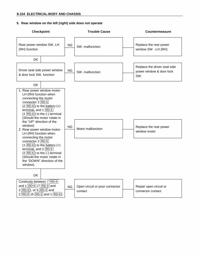
8-154 ELECTRICAL-BODY AND CHASSIS
5. Rear window on the left (right) side does not operate
Checkpoint Trouble Cause Countermeasure
Replace the driver seat sidepower window & door lockSW.
SW. malfunctionNG
Replace the rear powerwindow motor
Motor malfunctionNG
OK
Driver seat side power window& door lock SW. function
OK
Repair open circuit orconnector contact
Open circuit or poor connectorcontact
NG
Continuity between 7 RD-4
and 1 RD-5 (7 RD-3 and2 RD-6 ), or 5 RD-4 and2 RD-5 (5 RD-3 and 1 RD-6 )
1. Rear power window motor-LH (RH) function whenconnecting the motorconnector 2 RD-5(2 RD-6 ) to the battery (+)terminal, and 1 RD-5(1 RD-6 ) to the (-) terminal(Should the motor rotate inthe “UP” direction of thewindow)
2. Rear power window motor-LH (RH) function whenconnecting the motorconnector 2 RD-5(1 RD-6 ) to the battery (+)terminal, and 2 RD-5(2 RD-6 ) to the (-) terminal(Should the motor rotate inthe “DOWN” direction of thewindow)
Replace the rear powerwindow SW. -LH (RH)
SW. malfunctionNG
OK
Rear power window SW. LH(RH) function

ELECTRICAL-BODY AND CHASSIS 8-155
REMOVAL AND INSTALLATION
Switch
DRIVER SEAT SIDE POWER WINDOWSWITCHRemoval1. Remove the switch by pushing the spring with the tip of a
screwdriver.2. Disconnect the connector.
InstallationTo install, follow the removal steps in the reverse order.
SwitchFRONT PASSENGER’S POWER WINDOWSWITCHRemoval1. Remove the switch by pushing the spring with the tip of a
screwdriver.2. Disconnect the connector.
InstallationTo install, follow the removal steps in the reverse order.
SwitchREAR POWER WINDOW SWITCH-LH &RHRemoval1. Remove the switch by pushing the spring with the tip of a
screwdriver.2. Disconnect the connector.
InstallationTo install, follow the removal steps in the reverse order.
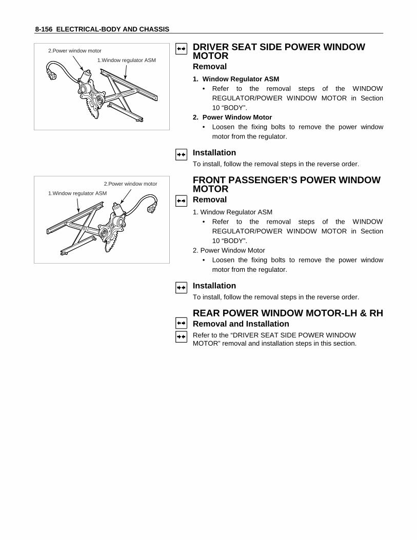
8-156 ELECTRICAL-BODY AND CHASSIS
1.Window regulator ASM
2.Power window motor DRIVER SEAT SIDE POWER WINDOWMOTORRemoval1. Window Regulator ASM
• Refer to the removal steps of the WINDOWREGULATOR/POWER WINDOW MOTOR in Section10 “BODY”.
2. Power Window Motor• Loosen the fixing bolts to remove the power window
motor from the regulator.
InstallationTo install, follow the removal steps in the reverse order.
1.Window regulator ASM
2.Power window motor FRONT PASSENGER’S POWER WINDOWMOTORRemoval1. Window Regulator ASM
• Refer to the removal steps of the WINDOWREGULATOR/POWER WINDOW MOTOR in Section10 “BODY”.
2. Power Window Motor• Loosen the fixing bolts to remove the power window
motor from the regulator.
InstallationTo install, follow the removal steps in the reverse order.
REAR POWER WINDOW MOTOR-LH & RHRemoval and InstallationRefer to the “DRIVER SEAT SIDE POWER WINDOWMOTOR” removal and installation steps in this section.

ELECTRICAL-BODY AND CHASSIS 8-157
INSPECTION AND REPAIR
X-4Power Window RelayCheck continuity between the relay terminals.1 - 5 .........................No continuity
(When battery voltage is applied between 1 and 2 )
1 - 5 .........................Continuity
FD-1
Harness side
Driver Seat Side Power Window Switch1. Harness Side Connector Circuit
Disconnect the switch connector, and check voltage andcontinuity between the harness side connector terminals asshown in the following table.
TerminalNo.
Wirecolor
Connecting to Check itemConnecting
terminalCheck condition Standard
7 G/YPower windowrelay
Voltage 2-Ground Starter SW “ON”Approx.
12V
15 L/B Power window
16 L/R motor
2 B Ground Continuity 5-Ground - Continuity
FD-12
Harness side
Front Passenger’s Power Window Switch1. Harness Side Connector Circuit
Disconnect the switch connector, and check voltage andcontinuity between the harness side connector terminals asshown in the following table.
Continuity-15-16Continuity

8-158 ELECTRICAL-BODY AND CHASSIS
TerminalNo.
Wirecolor
Connecting to Check itemConnecting
terminalCheck condition Standard
3 G/YPower windowrelay
Voltage 3-Ground Starter SW “ON”Approx.
12V
7 L/B Power window
5 L/R motor
2 FD-1 B Ground Continuity 2-Ground - Continuity
RD-3 RD-4
Harness side
Rear Power Window Switch-LH & RH1. Harness Side Connector Circuit
Disconnect the switch connector, and check voltage andcontinuity between the harness side connector terminals asshown in the following tables.
RD-4 (RR-LH)
TerminalNo.
Wirecolor
Connecting to Check itemConnecting
terminalCheck condition Standard
3 G/YPower windowrelay
Voltage 3-Ground Starter SW “ON”Approx.
12V
7 L/B Power window
5 L/R motor
2 FD-1 B Ground Continuity 2-Ground - Continuity
RD-3 (RR-RH)
TerminalNo.
Wirecolor
Connecting to Check itemConnecting
terminalCheck condition Standard
3 G/RPower windowrelay
Voltage 3-Ground Starter SW “ON”Approx.
12V
7 L/R Power window
5 L/R motor
2 FD-1 B Ground Continuity 2-Ground - Continuity
Continuity-7-5Continuity
ContinuityContinuity 7-5 -
ContinuityContinuity 7-5 -

ELECTRICAL-BODY AND CHASSIS 8-159
FD-1
Harness side
Driver Seat Side Power Window Motor1. Driver Seat Side Power Window Switch Connector
CircuitDisconnect the switch connector, apply the battery voltage(12V) to the harness side connector terminals and checkoperation.
Connecting terminals Operation
15 (L/B) 16 (L/R) direction
- + DOWN
+ - UP
FD-4
2. Driver Seat Side Power Window Motor ConnectorCircuitDisconnect the switch connector, apply the battery voltage(12V) to the motor side connector terminals and checkoperation.
Connecting terminals Operation
1 2 direction
+ - DOWN
- + UP
FD-12
Harness side
Front Passenger’s Power Window Motor1. Front Passenger’s Power Window Switch Connector
CircuitDisconnect the motor connector, apply the battery voltage(12V) to the harness side connector terminals and checkoperation.
Connecting terminals Operation
7 (L/B) 5 (L/R) direction
- + DOWN
+ - UP
FD-15
2. Front Passenger’s Power Window Motor ConnectorCircuitDisconnect the switch connector, apply the battery voltage(12V) to the motor side connector terminals and checkoperation.
Connecting terminals Operation
1 2 direction
+ - DOWN
- + UP

8-160 ELECTRICAL-BODY AND CHASSIS
RD-4
Harness side
Rear Passenger’s Power Window Motor-LH1. Rear Power Window Switch-LH Connector Circuit
Disconnect the motor connector, apply the battery voltage(12V) to the harness side connector terminals and checkoperation.
Connecting terminals Operation
7 (L/B) 5 (L/R) direction
- + DOWN
+ - UP
(LWB)
(SWB)RD-5
RD-9
2. Rear Power Window Motor-LH Connector CircuitDisconnect the switch connector, apply the battery voltage(12V) to the motor side connector terminals and checkoperation.
Connecting terminals Operation
1 2 direction
+ - DOWN
- + UP
RD-3
Harness side
Rear Power Window Motor-RH1. Rear Power Window Switch-RH Connector Circuit
Disconnect the motor connector, apply the battery voltage(12V) to the harness side connector terminals and checkoperation.
Connecting terminals Operation
7 (L/B) 5 (L/R) direction
- + DOWN
+ - UP
(LWB)
(SWB)RD-6
RD-10
2. Rear Power Window Motor-RH Connector CircuitDisconnect the switch connector, apply the battery voltage(12V) to the motor side connector terminals and checkoperation.
Connecting terminals Operation
1 2 direction
+ - DOWN
- + UP

ELECTRICAL-BODY AND CHASSIS 8-161
AUDIO, CLOCK AND CIGARETTE LIGHTER
PARTS LOCATION
H-9
BD-6
B-23
B-25
BD-1
RL-1RL-2
RL-3RL-4
B-12
P-7
P-8 P-9
I-13 FD-3 B-22
B-21
B-27
H-1H-8
H-16
ER-16
B-10
H-7H-3H-15
I-2
FD-14
I-9
I-5
I-7I-8
H-14
RELAY &FUSE BOX
P-1P-6

8-162 ELECTRICAL-BODY AND CHASSIS
CIRCUIT DIAGRAM
I-510
I-5
4
FD-3
2
FD-3
1
I-8
I-5
14
B
ACC
IG
ST
ER-161
ER-162
SW ; STARTER
P-8
P-6BATTP-1
P-9 P-7
P-7 : EARTH ; BODYP-8 : EARTH ; FRAMEP-9 : EARTH ; ENGINE
30B
/Y
9B/Y
5B/Y
MAINEB-360A
8B/R 3W/B
IGNEB-240A
3W
0.85R
3L/B
0.5G/R 0.5G/R
0.5G/W
H-3
12
H-3
13
I-5
6
I-5
15
I-5
7
I-5
16
I-7
STOPE-1010A
AUDIO(B),CLOCK,ROOME-915A
AUDIO,CIGARC-615A
I-13EARTH ; BODY (RH) 0.85BI-2EARTH ; BODY (LH) 0.85B
0.85
B
0.5W
0.5R
0.5W
0.5R
0.5G
R
0.5G
0.5G
R
0.5G
0.5Y
0.5L
0.5O
0.5B
0.85
B0.
85L
FUSE E-11(TAIL)
STOP LAMP SW
0.85
L0.
85L
0.85
R
CIG
AR
LIG
HT
ER
B-10
1
B-10
2
FD-14
2
FD-14
1
BD-1
2
BD-1
1
H-7
17
I-5
1
I-5
8
I-5
2
I-5
9
H-165
H-7
16
H-164
H-7
11
H-162
H-7
10
H-161
H-141
H-142
H-154
H-153
BD-6
2
BD-6
1
B-12
1
B-12
2
H-9
6
H-9
8
H-7
23
H-7
24
TWEETER-LH FT-LH
FRT. SPEAKER RR. SPEAKER(IF EQUIPPED)
FT-RH TWEETER-RH RR-LH RR-RH
AUDIO
H-14
H-715

ELECTRICAL-BODY AND CHASSIS 8-163
I-9
2
I-9
4
0.5G
/R
0.85
R
0.5O
0.5R
/G0.
5R/G
SW
; D
OO
R F
RT-
LH
0.5O
0.5B
CLOCK
RL-416:00
H-110
RL-3
H-8
2
ON OFF
8W
DOOR
ROOM LAMP-FRT
0.5O
0.5R
/G
RL-2
RL-1
ON OFF
8W
DOOR
ROOM LAMP-RR
H-8
1
I-9
3
B-23
1
0.5R
/G
SW
; D
OO
R R
R-L
H
B-25
1
0.5R
/G
SW
; B
AC
K D
OO
R
B-27
1
0.5R
/G
SW
; D
OO
R F
RT-
RH B-22
1
0.5R
/G
SW
; D
OO
R R
R-R
H B-21
1

8-164 ELECTRICAL-BODY AND CHASSIS
TROUBLESHOOTING
CIGARETTE LIGHTER1. Lighter does not pop out after being pushed in. It does not become hot.
Checkpoint Trouble Cause Countermeasure
Reinstall or replace the fuseNo. C-6 (15A)
Poor Fuse No. C-6 (15A, Fusebox) contact or blown
NG
Replace the lighterLighter continuity betweencenter part and outer area
Open circuit or poor connectorcontact
Repair open circuit orconnector contact
Voltage between connectorI-8 and the ground at
starter SW. is ACC position(Should be battery voltagepresent)
Open circuit or poor connectorcontact
NG
NG
OK
OK
OK
Audio system (System shouldreceive power)
Repair open circuit orconnector contact
Open circuit or poor connectorcontact
NGContinuity between connectorI-7 and the ground
2. Lighter pops out prematurely before becoming hot
Repair or replace the lighterand/or casing
Deformed lighter or casingNGLighter and casing
3. Lighter becomes too hot
Repair or replace the lighterand/or casing
Deformed lighter and casingNGLighter and casing

ELECTRICAL-BODY AND CHASSIS 8-165
4. Dome light does not light
Checkpoint Trouble Cause Countermeasure
Replace the dome light bulbBurned out the bulbNG
Repair or replace the domelight assembly
Dome light switch function Switch malfunction
Repair open circuit orconnector contact
Continuity betweenconnector 10 H-1 - LR-3 ,LR-1
Open circuit or poor connectorcontact
NG
NG
OK
OK
Dome light bulb continuity
5. Dome light does not go out
Repair or replace the doorswitch
Switch malfunction or foreignmaterial switch
NG
Repair short circuit orconnector contact
Continuity betweenconnector LR-4 , LR- 2 -ground when shutting the door(Should be no continuity)
Short circuitNG
OK
Door switch function (Bothside)

8-166 ELECTRICAL-BODY AND CHASSIS
REMOVAL AND INSTALLATION
DOME LIGHTRemoval1. Remove the dome light lens free.2. Remove three dome light fixing screws.3. Remove the wiring connector.4. Remove the dome light.
5. Pull the bulb to remove it.
InstallationFollow the removal procedure in the reverse order to install thedome light.Pay close attention to the important points mentioned in thefollowing paragraphs.
BulbBe absolutely sure that the dome light bulb is correctlyinstalled.This will prevent a poor contact and an open circuit.
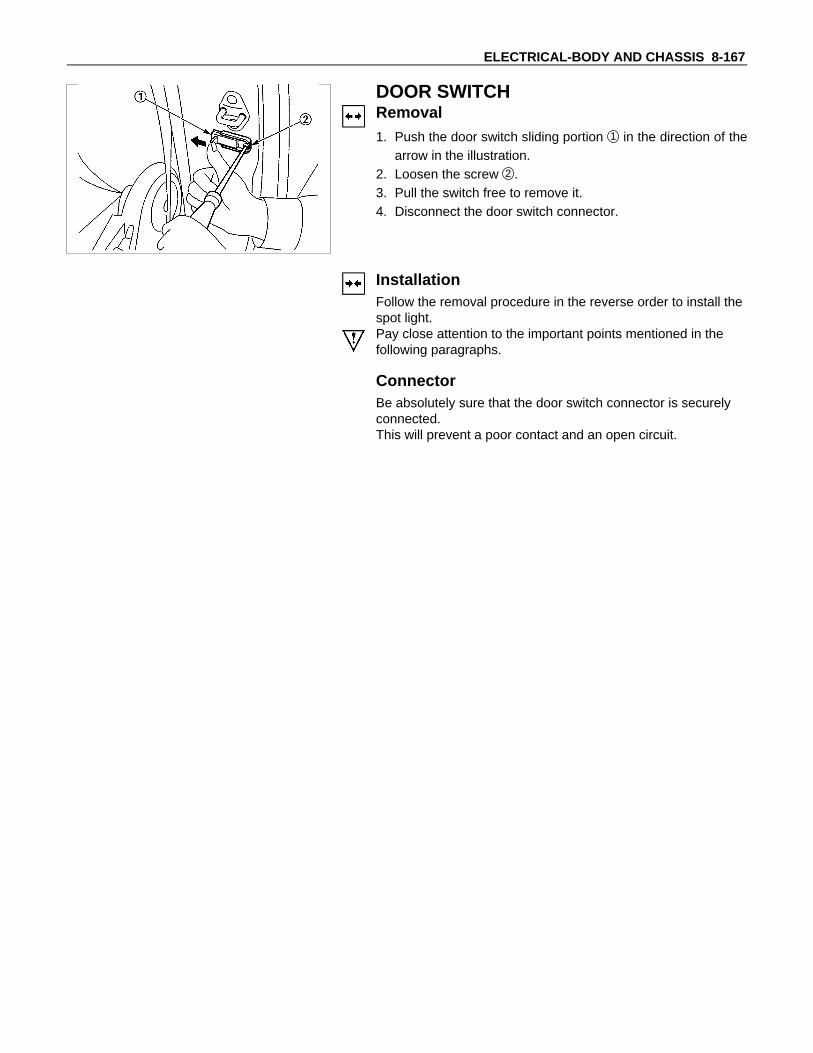
ELECTRICAL-BODY AND CHASSIS 8-167
DOOR SWITCHRemoval1. Push the door switch sliding portion 1 in the direction of the
arrow in the illustration.2. Loosen the screw 2 .3. Pull the switch free to remove it.4. Disconnect the door switch connector.
InstallationFollow the removal procedure in the reverse order to install thespot light.Pay close attention to the important points mentioned in thefollowing paragraphs.
ConnectorBe absolutely sure that the door switch connector is securelyconnected.This will prevent a poor contact and an open circuit.
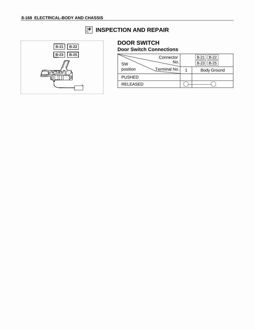
8-168 ELECTRICAL-BODY AND CHASSIS
INSPECTION AND REPAIR
B-21 B-22
B-23 B-25
DOOR SWITCHDoor Switch Connections
Connector
SW No.B-21 B-22
B-23 B-25
position Terminal No. 1 Body Ground
PUSHED
RELEASED
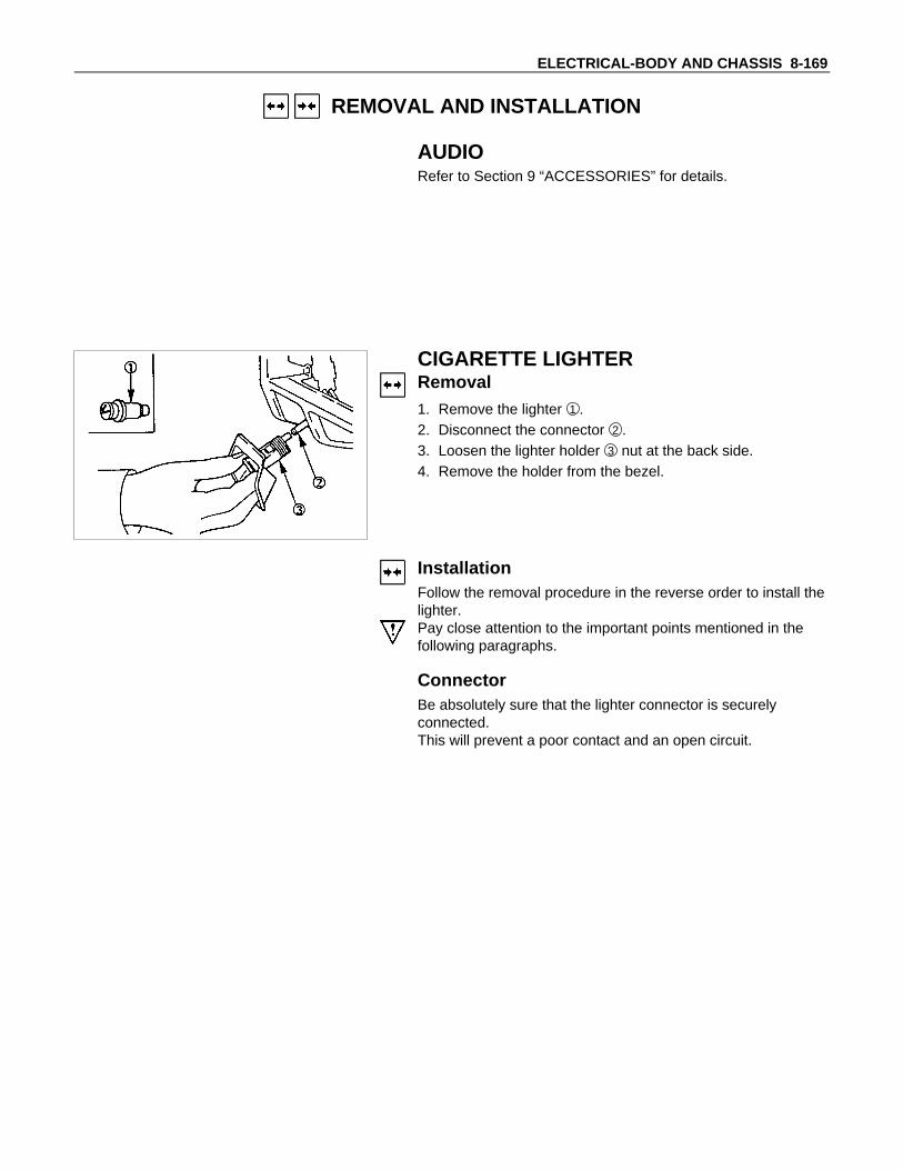
ELECTRICAL-BODY AND CHASSIS 8-169
REMOVAL AND INSTALLATION
AUDIORefer to Section 9 “ACCESSORIES” for details.
CIGARETTE LIGHTERRemoval1. Remove the lighter 1 .2. Disconnect the connector 2 .3. Loosen the lighter holder 3 nut at the back side.4. Remove the holder from the bezel.
InstallationFollow the removal procedure in the reverse order to install thelighter.Pay close attention to the important points mentioned in thefollowing paragraphs.
ConnectorBe absolutely sure that the lighter connector is securelyconnected.This will prevent a poor contact and an open circuit.

8-170 ELECTRICAL-BODY AND CHASSIS
POWER DOOR MIRROR
PARTS LOCATION
P-7
P-8
H-15
I-15ER-16
P-9
H-14
FD-16
I-13
FD-5
RELAY &FUSE BOX
P-6P-1

ELECTRICAL-BODY AND CHASSIS 8-171
CIRCUIT DIAGRAM
I-15
4
3W/B
3L/B
0.85
L
0.85L
0.5B
/W0.
5B/W
0.5B
/R
0.5W
/G
B
ACCIGST
SW ;STARTER
ER-162
ER-16
1
H-3
12
AU
DIO
P-8
P-6BATTP-1
P-9 P-7
P-7 : EARTH ; BODYP-8 : EARTH ; FRAMEP-9 : EARTH ; ENGINE
30B
/Y
9B/Y
5B/Y
8B/R
IGNEB-240A
CIGAR, MIRRORC-615A
I-159
0.5W/BRVI-15
7
0.5W/GLVI-15
8
0.5VRHI-15
5
0.5B/RLHI-15
10
0.5B/WCI-15
1
H-152
H-155
H-156
I-13EARTH ; BODY (RH) 0.85B
0.85
B
0.5B
H-14
8
H-14
7
H-14
3
MLR
MUD
FD-16
2
FD-16
1
FD-16
3
0.5B
/W
0.5V
0.5W
/B
MLR
MUD
FD-5
2
FD-5
1
FD-5
3
MIRROR(LH) MIRROR(RH)
RH
LH
SW ; REMOTE CONTROL MIRROR

8-172 ELECTRICAL-BODY AND CHASSIS
TROUBLE SHOOTING
QUICK CHART FOR CHECK POINT
Check Point Fuse Door Mirror Door Mirror
Trouble Mode
C-6(15A)
ControlSwitch
LH RH
1. Mirrors on the both sides do not operate
2. Mirror on the left (or right) side does notoperate
3. Mirrors on the both sides operate only inthe vertical(or horizontal) direction
4. Mirror on the left side operates only in thevertical(or horizontal) direction
5. Mirror on the right side operates only inthe vertical(or horizontal) direction
CableHarness

ELECTRICAL-BODY AND CHASSIS 8-173
TROUBLESHOOTING
DOOR MIRROR CONTROL SWITCH1. Mirrors on the both sides do not operate
Checkpoint Trouble Cause Countermeasure
Reinstall or replace the fuseNo. C-6 (15A)
Poor fuse contact or blownNG
Repair grounding point( I-13 ) contact
Grounding point ( I-13 ) Poor grounding point contact
Repair an open circuit or apoor connection of theconnectors between the fuseNo. C-6 (15A) and 4 I-15
Voltage between the doormirror control SW. harnessside connector terminal4 I-15 and the ground(Should be battery voltagepresent)
Open circuit or poor connectorcontact
NG
NG
OK
OK
OK
Fuse No. C-6 (15A, Fuse box)
Repair open circuit orconnector contact
Open circuit or poor connectorcontact
NG
Continuity between the doormirror control SW harnessside connector terminal9 I-15 and ( I-13 )
Replace the door mirrorcontrol SW.
Door mirror control SW.function
SW. malfunctionNG
OK
Repair open circuit orconnector contact
Continuity between 1 I-15
and 6 H-15 (or 8 H-14 )Open circuit or poor connectorcontact
NG
OK
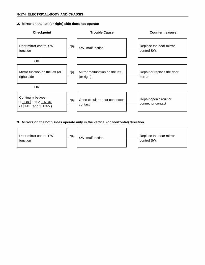
8-174 ELECTRICAL-BODY AND CHASSIS
2. Mirror on the left (or right) side does not operate
Checkpoint Trouble Cause Countermeasure
Replace the door mirrorcontrol SW.
SW. malfunctionNG
Repair or replace the doormirror
Mirror function on the left (orright) side
Mirror malfunction on the left(or right)
Repair open circuit orconnector contact
Continuity between1 I-15 and 2 FD-16
(1 I-15 and 2 FD-5 )
Open circuit or poor connectorcontact
NG
NG
OK
OK
Door mirror control SW.function
3. Mirrors on the both sides operate only in the vertical (or horizontal) direction
Replace the door mirrorcontrol SW.
SW. malfunctionNGDoor mirror control SW.function

ELECTRICAL-BODY AND CHASSIS 8-175
4. Mirror on the left side operates only in the vertical (or horizontal) direction
Checkpoint Trouble Cause Countermeasure
Replace the door mirrorcontrol SW.
SW. malfunctionNG
Repair or replace the doormirror
Door mirror function Door mirror malfunction
Repair open circuit orconnector contact
Continuity between8 I-15 and 3 FD-16
(10 I-15 and 1 FD-16 )
Open circuit or poor connectorcontact
NG
NG
OK
OK
Door mirror control SW.function
5. Mirror on the right side operates only in the vertical (or horizontal) direction
Replace the door mirrorcontrol SW.
Door mirror controlmalfunction
NG
Repair or replace the doormirror
Door mirror function Door mirror malfunction
Repair open circuit orconnector contact
Continuity between7 I-15 and 3 FD-5 (5 I-15
and 1 FD-5 )
Open circuit or poor connectorcontact
NG
NG
OK
OK
Door mirror control SW.function

8-176 ELECTRICAL-BODY AND CHASSIS
REMOVAL AND INSTALLATION
DOOR MIRROR CONTROL SWITCHRemoval1. Instrument Panel Cluster Assembly
• Refer to section 10 “BODY” for instrument panel clusterassembly removal steps.
2. Door Mirror Control Switch• Disconnect the switch connector.• To remove the switch, push the lock from the back side
of the cluster assembly.
InstallationTo install, follow the removal steps in the reverse order.
DOOR MIRRORRemoval and InstallationRefer to the DOOR MIRROR in section 10 “BODY”.
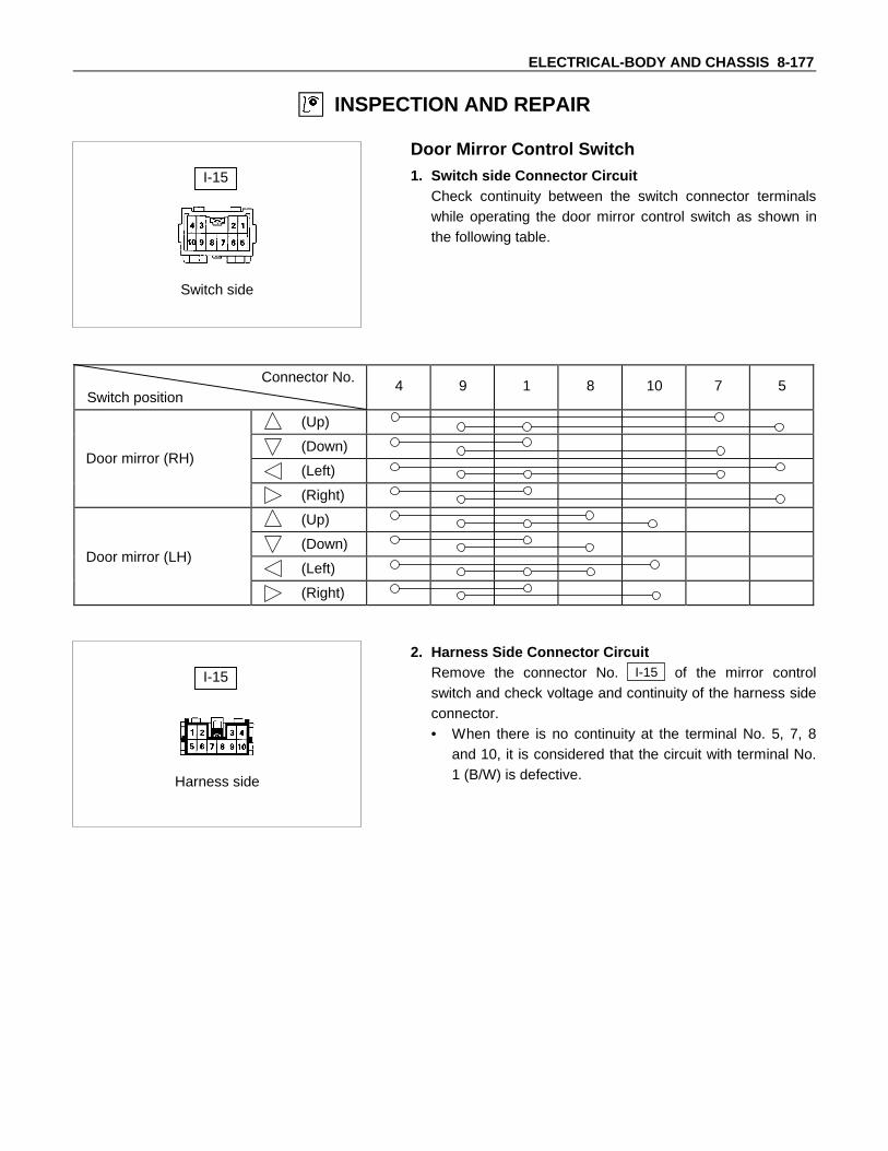
ELECTRICAL-BODY AND CHASSIS 8-177
INSPECTION AND REPAIR
Switch side
I-15
Door Mirror Control Switch1. Switch side Connector Circuit
Check continuity between the switch connector terminalswhile operating the door mirror control switch as shown inthe following table.
Connector No.Switch position
4 9 1 8 10 7 5
(Up)
(Down)
(Left)
(Right)
(Up)
(Down)
(Left)
(Right)
Harness side
I-15
2. Harness Side Connector CircuitRemove the connector No. I-15 of the mirror controlswitch and check voltage and continuity of the harness sideconnector.• When there is no continuity at the terminal No. 5, 7, 8
and 10, it is considered that the circuit with terminal No.1 (B/W) is defective.
Door mirror (RH)
Door mirror (LH)

8-178 ELECTRICAL-BODY AND CHASSIS
• When there is no continuity at either one of the circuitNo, 5, 7, 8, or 10, the motor in the mirror of the circuit orthe circuit itself is defective.
TerminalNo.
Wirecolor
Connection to Check itemConnecting
terminalCheck condition Standard
1 B/WLH mirror & RHmirror
Continuity 1-Ground - No continuity
4 L Fuse C-6 (15A) Voltage 4-GroundStarter SW “ACC”
positionApprox.
12V
5 V RH mirror-LH/RH 5-1 -
7 W/B RH mirror-Up/Down 7-1 -
8 W/G LH mirror-Up/Down Continuity 8-1 - Continuity
9 B Ground 9-Ground -
10 B/R LH mirror-LH/RH 10-1 -
Harness side
I-15
Door Mirror1. Door Mirror Control Switch Connector Circuit
Disconnect the switch connector ( I-15 ), apply the batteryvoltage to the harness side connector terminals and checkits function.
ConnectorNo.
I-15Operating
TerminalMirror No.
10 5 1 8 7direction
+ - Left
- + Right
- + Up
+ - Down
+ - Left
- + Right
- + Up
+ - Down
Left
Right

ELECTRICAL-BODY AND CHASSIS 8-179
Door mirror sideDoor mirror side
FD-5 FD-16
2. Door Mirror Connector CircuitDisconnect the door mirror connector, apply the batteryvoltage to the door mirror side connector ( FD-5 andFD-16 ) terminals and check its function.
Connector No. FD-5 FD-16
Terminal No.Operation
1 2 3
Up - +
Down + -
Left + -
Right - +

8-180 ELECTRICAL-BODY AND CHASSIS
TRANSMISSION CONTROL MODULE (A/T)
PARTS LOCATION
P-7
P-8
H-3
H-1H-2
ER-16
ER-13
TE-4TE-1
TE-3
TE-2
TE-11
B-13
I-4 I-3
B-19
B-14 B-9
H-9
P-9
H-5H-6
ER-11RELAY &FUSE BOX
P-6P-1
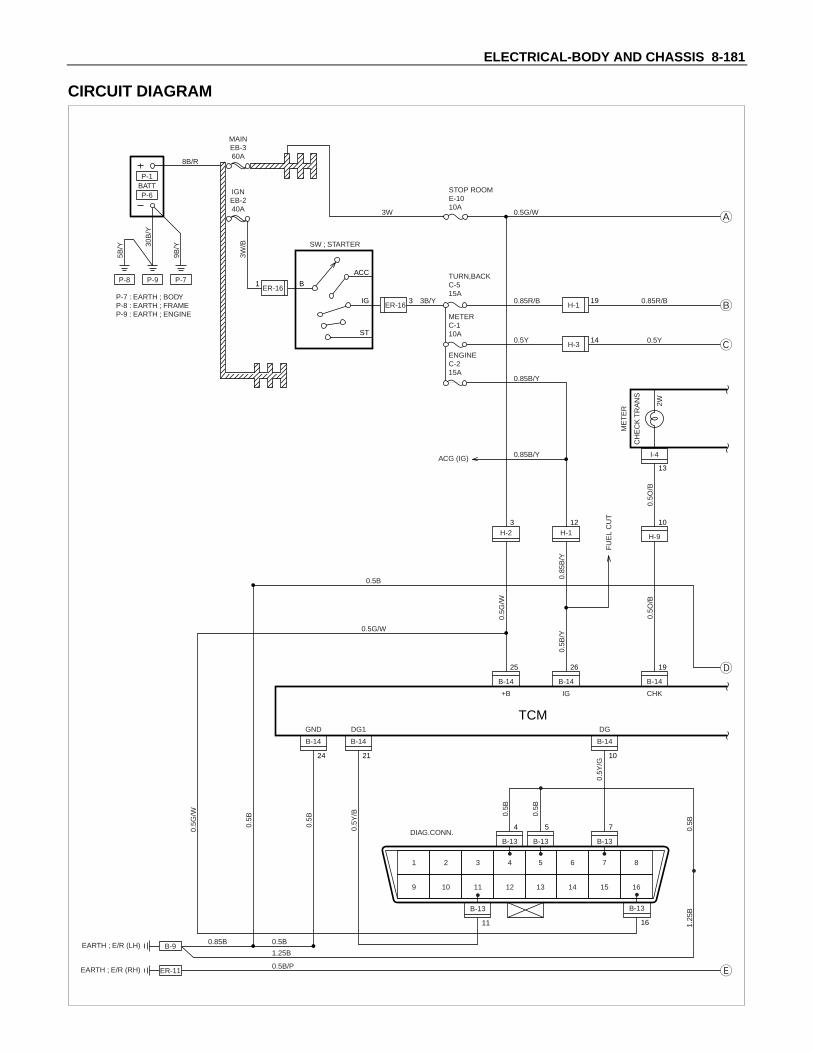
ELECTRICAL-BODY AND CHASSIS 8-181
CIRCUIT DIAGRAM
B-13
11
P-8
P-6BATTP-1
P-9 P-7
P-7 : EARTH ; BODYP-8 : EARTH ; FRAMEP-9 : EARTH ; ENGINE
30B
/Y
9B/Y
3W/B
5B/Y
MAINEB-360A
8B/R
IGNEB-240A
B
ACC
IG
ST
ER-161
H-119
STOP ROOME-1010A
0.5G/W3W
0.85R/B3B/Y 0.85R/B
0.5Y0.5Y
0.85B/Y
0.85B/Y
0.5O
/B0.
5O/B
0.5G
/W
0.5B
/Y
0.5B
0.5Y
/B
0.5Y
/G
0.5B
0.5B
0.5B
1.25
B
0.85
B/Y
FU
EL
CU
T
ME
TE
R
CH
EC
K T
RA
NS
2W
TURN,BACKC-515A
METERC-110A
ENGINEC-215A
ACG (IG)
H-314
ER-163
SW ; STARTER
B-9
ER-11
EARTH ; E/R (LH)
EARTH ; E/R (RH)
0.85B 0.5B
0.5B
1.25B
0.5B/P
0.5B
GND DG1 DG
+B IG
B-14
26
H-112
H-23
B-14
24
B-14
21
B-14
10
CHK
B-14
19
B-14
25
B-13
4
B-13
5
B-13
7
H-9
10
I-4
13
1
9
2
10
3 4
11 12
5
13
6
14
7
15
8
16
DIAG.CONN.
TCM
B-13
16
0.5G/W
0.5G
/W

8-182 ELECTRICAL-BODY AND CHASSIS
0.5R
/G
0.5R
/W
0.5Y
/L
Vt+
B-14
20
Vth
B-14
18
Vt-
B-14
8
H-513
H-514
H-515
TE-11
3
TE-11
2
TE-11
1
OUT
THROTTLE POSITION SENSOR(INJ PUMP)
TE-4
6
H-6
8
H-6
3
H-6
2
H-6
1
B-14
2
B-14
3
B-14
1
I-3
10
I-3
9
OD
OF
F IN
D
1.4W
0.5Y
0.85
R/B
0.85R/B
0.85
R/Y
0.5P
/G
0.5P
/L
0.5P
/B
0.5G
/Y
0.5G
/Y
0.5P
/G
0.5B
R/B
0.5P
0.5P
0.5L
/B0.
5L/B
0.5B
/P
0.5P
/W
SH
IFT
SO
L.1
T/M
WIR
E
0.5B
R/W
0.5B
R/R
0.5B
R/B
0.5B
R/W
0.5B
R/R
BA
CK
UP
LA
MP
0.5P
/L
0.5P
/B
INH
IBIT
OR
SW
0.5O
/L0.
5O/L
0.5O
/L0.
5B
N
B-14
9
OD1
SP1
2B LB
B-14
14
BK
B-14
6
H-56
H-57
SP2+
B-14
22
TE-3
2
(SP2G)SP2-
B-14
23
H-58
S1
B-14
13
S2
B-14
12
S3
B-14
11
RB N 2B LB
E
TE-4
5
TE-4
4
TE-4
10
TE-4
8
ER-13
1
0.5G
/W
0.5G/W
SW
; S
TOP
LA
MP
ER-13
2
H-15
STO
P L
AM
P
B-19
1
SW
; O
D O
FF
(SE
LEC
T L
EV
ER
)
B-19
5
TE-2
2
TE-2
1
TE-2
3
H-510
H-59
TE-3
1
TE-1
2
TE-1
1
H-5
16
H-511
(MIS
SIO
N)
SP
2
VE
HIC
LE S
PE
ED
SE
NS
OR
SH
IFT
SO
L.2
L-U
P S
OL.
H-97
H-64
H-33
TCM
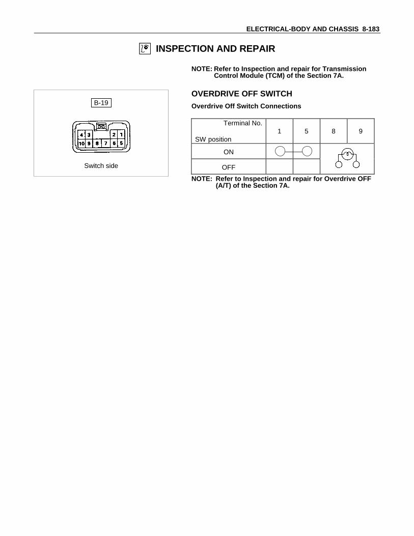
ELECTRICAL-BODY AND CHASSIS 8-183
INSPECTION AND REPAIR
NOTE: Refer to Inspection and repair for TransmissionControl Module (TCM) of the Section 7A.
B-19
Switch side
OVERDRIVE OFF SWITCHOverdrive Off Switch Connections
Terminal No.
SW position1 5 8 9
ON
OFF
NOTE: Refer to Inspection and repair for Overdrive OFF(A/T) of the Section 7A.

8-184 ELECTRICAL-BODY AND CHASSIS
CONNECTOR LIST
No. Connector face No. Connector face
AR-1
AR-2
AR-3

ELECTRICAL-BODY AND CHASSIS 8-185
No. Connector face No. Connector face
B-1 B-11
B-2 B-12
B-3 B-13
B-4 B-14
B-5 B-15
B-6 B-16
B-7 B-17
B-8 B-18
B-9 B-19
B-10 B-20

8-186 ELECTRICAL-BODY AND CHASSIS
No. Connector face No. Connector face
B-21
B-22
B-23
B-24
B-25
B-26
B-27
B-28

ELECTRICAL-BODY AND CHASSIS 8-187
No. Connector face No. Connector face
BD-1
BD-2
BD-3
BD-4
BD-5
BD-6
BD-7
BD-8
BD-9
BD-10
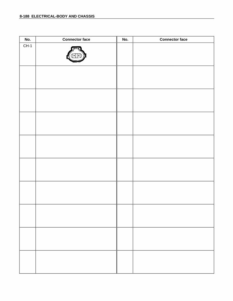
8-188 ELECTRICAL-BODY AND CHASSIS
No. Connector face No. Connector face
CH-1

ELECTRICAL-BODY AND CHASSIS 8-189
No. Connector face No. Connector face
ER-1
1 2
ER-11
ER-2 ER-12
NOT USED
ER-3 ER-13
ER-4 ER-14
ER-5 ER-15
ER-6 ER-16
ER-7
ER-8
ER-9
ER-10

8-190 ELECTRICAL-BODY AND CHASSIS
No. Connector face No. Connector face
FD-1 FD-11
FD-2 FD-12
FD-3 FD-13
FD-4 FD-14
FD-5 FD-15
FD-6
NOT USED
FD-16
FD-7
NOT USED
FD-8
NOT USED
FD-9
NOT USED
FD-10
NOT USED

ELECTRICAL-BODY AND CHASSIS 8-191
No. Connector face No. Connector face
H-11 2 3 46 7 10 118 9
21 2214 15 16 1720
51319
12182423
4 3 2 111 10 7 69 8
22 2117 16 15 1423
121824
5131920
H-11
H-2 H-12
H-3 H-13
H-4 H-14
H-5 H-15
H-6 H-16
H-7 H-17
H-8
H-9
2016 17 18 19151412 1311106 7 8 9542 31
1519 18 17 16201113 121459 8 7 61013 24
H-10

8-192 ELECTRICAL-BODY AND CHASSIS
No. Connector face No. Connector face
I-1 I-11
I-2 I-12
I-3
2 31 5 6413 14128 9 10 117
I-13
I-4
3 41 6 7515 161410 11 12 138
29
I-14
I-5 I-15
I-6
3 41 2
6 7 8
5
I-16
I-7
I-8
I-9
1 2 3 4
I-10

ELECTRICAL-BODY AND CHASSIS 8-193
No. Connector face No. Connector face
P-1
P-2
P-3
P-4
P-5
P-6
P-7
P-8
P-9
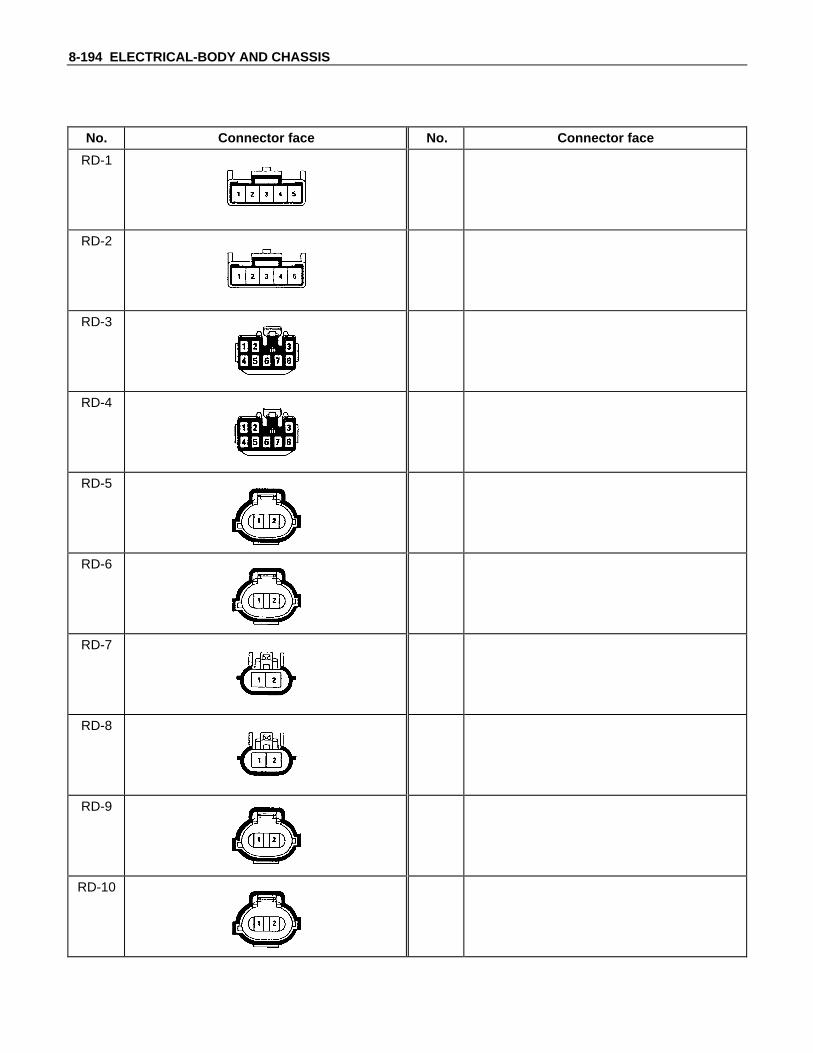
8-194 ELECTRICAL-BODY AND CHASSIS
No. Connector face No. Connector face
RD-1
RD-2
RD-3
RD-4
RD-5
RD-6
RD-7
RD-8
RD-9
RD-10
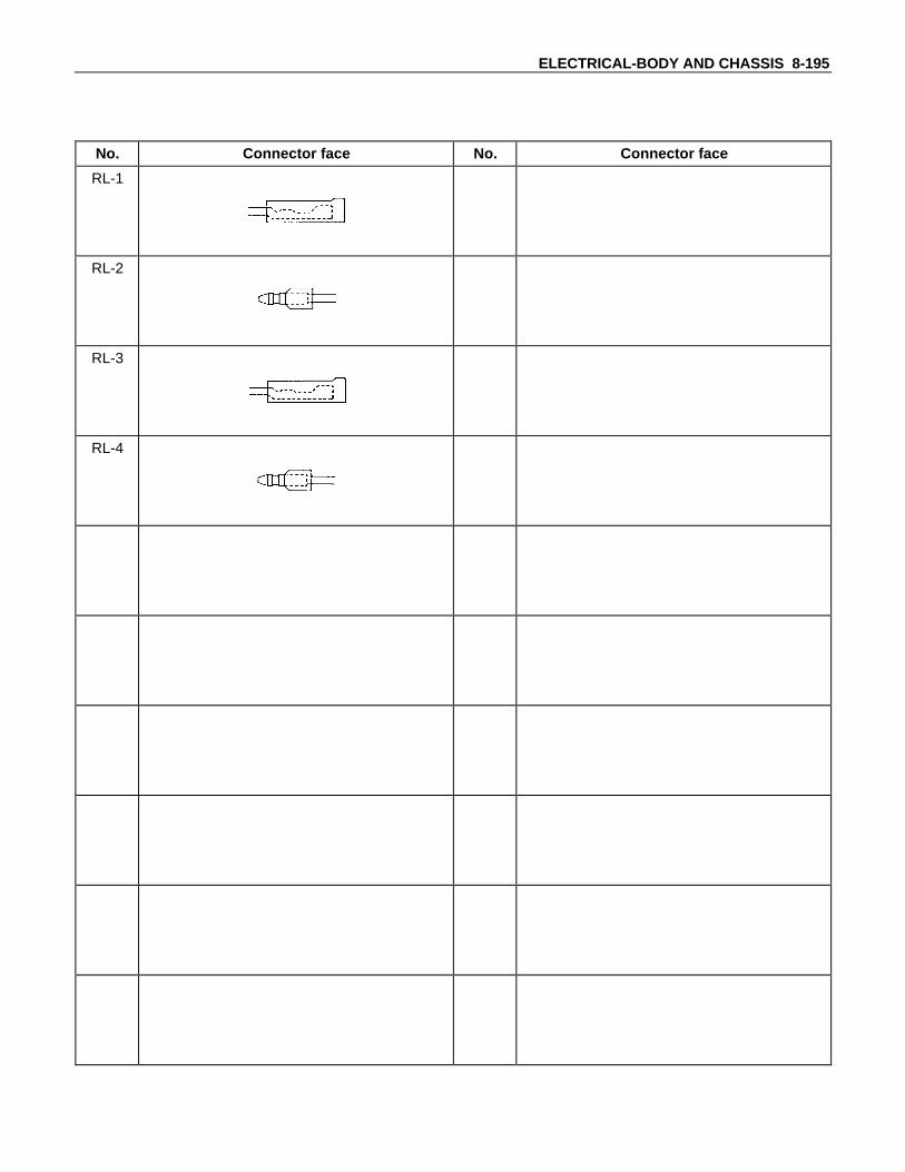
ELECTRICAL-BODY AND CHASSIS 8-195
No. Connector face No. Connector face
RL-1
RL-2
RL-3
RL-4

8-196 ELECTRICAL-BODY AND CHASSIS
No. Connector face No. Connector face
TE-1 TE-11
TE-2 TE-12
TE-3
TE-4
TE-5
TE-6
TE-7
TE-8
TE-9
TE-10

ELECTRICAL-BODY AND CHASSIS 8-197
No. Connector face No. Connector face
X-1 X-11
X-2
X-3
X-4
X-5
X-6
NOT USED
X-7
X-8
X-9
X-10

MEMO

TBELC-WE-0065 IN
You are requested to order this manual using themanual number that is shown above.
This manual is applicable for vehicles in Indonesia.
All rights reserved, This manual may not bereproduced in whole or in part, without the permissionin writing of ISUZU MOTORS LIMITED.
Issued by
ISUZU MOTORS LIMITED
INTERNATIONAL SERVICE DEPARTMENT
Tokyo, Japan
First edition June, 2000

No. TBELC-WE-0065 IN