section 16100 electrical - bagleyconstruction.net. conduit system for telephone system. ......
TRANSCRIPT
16-022 A New Educational Building for First Baptist Church of Alma
16100-1
SECTION 16100 ELECTRICAL
1. SCOPE: 1.1 General: Provide a complete electrical system as described herein and as shown on the
drawings. 1.2 Items Included: Items under Division 16100 shall include but not be limited to:
A. Power and lighting distribution complete, beginning with main panel and extending through all branch circuits. This shall include all raceways, boxes, conductors and disconnect switches for all equipment served.
B. Lighting fixtures and lamps.
C. Devices and Plates: This shall include all receptacles, light switches, blank
plates and cover plates.
D. Panelboard, breakers and switches.
E. Conduit system for telephone system.
F. Conduit system for computer data cable.
G. Conduit system for alarm system.
H. Fire alarm system additions and modifications for the Activities building. I. New Fire Alarm system complete for areas indicated.
2. APPLICABLE SPECIFICATIONS AND CODES: 2.1 All work shall conform to the current National Electric Code and all local codes and
addenda. All materials and equipment included in Underwriter's Label Service shall bear that label. Where requirements of these specifications and the accompanying drawings exceed the codes, conform to these specifications.
3. COMPLETION OF WORK: 3.1 Testing: At the completion of work, a test shall be made and the entire system shall be
shown to be in perfect working condition. The following shall be made available to personnel conducting the test:
A. Electrician with hand tools
B. Accurate voltmeter
C. Clamp-on ammeter
D. Test lamp
E. Phase rotation indicator

16-022 A New Educational Building for First Baptist Church of Alma
16100-2
F. Complete electrical specifications and drawings with addenda and revisions. 3.2 Submittal: Upon completion of work, submit for approval three bound copies of the
following: A. Certificate of final inspection from local authorities
B. Details of operations and maintenance of equipment. This shall include
corrected shop drawings, wiring diagrams, spare parts list and recommended maintenance procedure.
C. Instructions: After completion and at a time convenient to the Owner, qualified
mechanics shall thoroughly familiarize the Owner's personnel with the operation and the maintenance of the items listed under "Submittal".
4. SPACE CONDITIONS: 4.1 All apparatus shall fit into the available spaces in the building and must be introduced into
the building so as not to cause damage to the structure. All equipment requiring service shall be accessible.
5. DRAWINGS: 5.1 Drawings are diagrammatic and show generally the location of the lighting, lamps, wiring,
raceways, switches and accessories and are not to be scaled. All dimensions shall be verified at the building site. Prefabrication of work from drawings shall be at contractor's risk.
6. WORKMANSHIP AND MATERIALS: 6.1 Workmanship: All work necessary to complete the project shall be executed in a
thorough, neat and workmanlike manner. 6.2 Materials: All materials shall be new and equipment included in Underwriter's Label
Service shall bear that label. 6.3 Substitutions:
A. Where equipment is specified herein or on drawings by manufacturer's names or model numbers, this shall denote minimum requirements as to quality, type, capacity, function and performance.
B. Substitutions of specified items will be considered only if written request has
been submitted to the Architect and Engineer for approval at least ten days prior to the receipt of bid proposals. Each request shall include a description of the proposed substitute, the name of material or equipment for which it is to be substituted, drawings, cuts, performance and test data for an evaluation and a statement from the equipment manufacturer's representative that the items to be substituted meet or exceed the specifications of the item substituted for. Requests for substitutions which do not comply with the requirements of this paragraph will not be considered.
C. If the substitution is allowed, such approval will be set forth in an addendum. No
other substitution shall be allowed. Verbal approval for substitution shall not be valid.
16-022 A New Educational Building for First Baptist Church of Alma
16100-3
7. SHOP DRAWINGS AND CUTS: 7.1 General:
A. Contractor agrees that the purpose of shop drawing submittals is to demonstrate to the Engineer that the Contractor understands the design concept, that he demonstrate his understanding by indicating which equipment and material he intends to furnish and install and by detailing the fabrication and installation method he intends to use. Approval of shop drawings will be general, is only for conformance with the design concept of the project and in compliance with the information given in the contract document, and is subject to coordination by the Contractor with other trades; it is not an approval of quantities, or dimensions, nor an authorization for extra work. The Engineer's approval of such drawings, schedules or cuts shall not relieve the Contractor from responsibility for deviation from drawings or specifications, unless he has in writing called the Engineer's attention to such deviation at the time of submission, and has received from the Engineer, in writing, permission for such deviations, nor shall it relieve him from responsibility for errors of any sort in shop drawing or schedules.
B. Shop drawings shall be stamped by the Engineer with the following
classifications:
1. REVIEWED [ ] NO EXCEPTIONS TAKEN: No corrections, no marks. Contractor shall submit copies for distribution.
2. REVIEWED [ ] MAKE CORRECTIONS NOTED: A few minor
corrections. All items may be fabricated as marked up without further resubmission. Submit copies for distribution.
3. REVISE AND RESUBMIT [ ]: Items not noted to be corrected may be
fabricated at the Contractor's option. Contractor shall resubmit drawings with corrections noted.
4. REJECTED [ ]: Major corrections or not in accordance with the
contract documents. No items shall be fabricated. Contractor shall correct and resubmit drawings.
7.2 Preparer's Identification: The name and telephone number of the individual preparing
the submittal shall be included on the index sheet so that questions concerning the submittal can be directed to that person.
7.3 Contractor's Approval: Each copy of shop drawings and cuts shall be signed and dated
by Contractor as evidence of checking to ensure compliance with plans and specifications.
7.4 Submittals: Shall be assembled, bound in a three-ring binder with an index sheet and
shall be submitted at one time unless unavailable drawings would delay project. Partial submittals will be identified as such with a statement as to which equipment is missing, the reason why it is missing, and approximate submittal date of the missing items. Submittals not complying with the provisions of this paragraph will be returned without action.
7.5 Each submittal sheet shall clearly contain the manufacturer's name, model number, and
all options included. Extraneous information on each sheet shall be crossed out.

16-022 A New Educational Building for First Baptist Church of Alma
16100-4
7.6 Submittals shall include but not be limited to:
Panelboards Circuit Breakers Disconnect Switches Starters and Contactors Wiring Devices and Plates Lighting Fixtures Fire Alarm System Conduit and Wire
8. APPARATUS PROVIDED UNDER OTHER SECTIONS: 8.1 General: No roughing shall be done until roughing drawings are furnished. 8.2 Mechanical Equipment:
A. Division 15:
1. Provide and install all power wiring up to disconnects, starters, contactors, freezestats, firestats and other control devices. Provide conduit, fuses, wiring and disconnect switches.
2. Firestats, freezestats, aquastats, emergency shut-down devices and
other electrical control devices are furnished and mounted under other sections.
B. Other Equipment (break room equipment, etc.): Connect for operation and
provide any appurtenances required for operation. Refer to appropriate sections of these specifications and shop drawings for more details.
9. SERVICE: 9.1 General: Make arrangements with Power Company for new service at new location. 9.2 Voltage: 208Y/120V, 3-phase, 4-wire. 10. CONDUIT: 10.1 General: Conduit shall be galvanized rigid conduit, intermediate metallic conduit or
electrical metallic tubing. Conduits 1-1/2" and larger, exposed below 5'-0"; branch conduit to motors, conduits in ground, slabs or walls on or below grade; or exposed to weather shall be IMC or rigid. Elsewhere conduit shall be EMT. Contractor shall have option of providing Schedule 40 PVC with separate ground conductor below floor slab.
Type MC (pre-wired metal clad) shall be acceptable for general power wiring. 10.2 Connectors and Couplings: Same material and finish as raceway. IMC rigid shall be
threaded. EMT shall be split-right compression type. Indenter or set screw type are not acceptable.
10.3 Threads: Cut clean and remove rough edges. Running threads shall not be used. 10.4 Pullboxes: Specified in NEC Article 370. 10.5 Insulating Bushings: On all conduits entering raceways, pullboxes, cabinets, stubs,
panelboards, switchboard and motor control centers.
16-022 A New Educational Building for First Baptist Church of Alma
16100-5
10.6 Insulated Throat Connectors: On all EMT connections and on EMT entering outlet
boxes, cabinets, panels, switchboard and motor control centers. 10.7 Connections to Motors: Where over 18" from walls or column, a vertical conduit,
minimum size 3/4" attached to ceiling and floor with wiring into and from this conduit with flexible conduit and condulets.
10.8 Metal Conduits in Contact with Ground: Coat complete with two coats of asphaltic paint
or use conduit with 20 mil bonded coat of PVC. 10.9 Expansion Fittings: APPLETON, CROUSE-HINDS or O.Z. at all expansion joints. 10.10 Capping: Cap conduits exposed during construction to prevent entrance of moisture or
foreign matter, use T&B Push-Pennies. 10.11 Plugging: All conduit runs which extend from interior to exterior of building and those
that enter and leave refrigerated spaces shall be sealed to prevent the circulation of air. This shall be done by stuffing the conduit ends with wicking where the conduit run terminates inside the building or outside the refrigerated spaces in the outlet box or panel, as the case may be.
10.12 Manufacturers: ALLIED, CLIFTON, CAVALIER, JONES & LAUGHLIN, REPUBLIC,
TRIANGLE, WHEATLAND, WHEELING or YOUNGSTOWN. 10.13 Conduit Routing:
A. Clearances: Maintain 3" crossing hot piping and 12" paralleling.
B. Concealed: Where possible.
C. Exposed Routings: Run parallel or at right angles to the building lines.
D. Supports: Individual runs shall be anchored in place within 3' of changes in direction and at intervals not over 8' by means of straps or clamps specifically designed for the purpose. Wire, hanger iron, nails and other means shall not be used. Do not strap to the piping. Multiple runs shall be supported by assemblies or trapeze type hangers to provide a rigid installation. Anchor supports by means of toggle bolts on hollow masonry units, expansion anchors on solid masonry units and machine screws in steel work.
11. FLEXIBLE CONDUIT: 11.1 General: Short lengths for connection to rotating or vibrating machinery or equipment, 6'
lengths maximum for connection to lighting troffers. Flexible connections to motors shall not be less than four diameters nor more than 24" in length and shall be liquid tight neoprene coated for motor connections and where subjected to moisture. Provide separate grounding conductor in flexible conduits.
11.2 Connectors: Steel, zinc or cadmium plates. Fittings that anchor the conduit by means
of set screws are not acceptable. 12. CONDUCTORS (50 TO 600 VOLTS): 12.1 General: Minimum size AWG 12 copper with minimum conductance of 98% unless
noted otherwise, solid for #10 and smaller, stranded for #8 and larger installed in

16-022 A New Educational Building for First Baptist Church of Alma
16100-6
continuous conduit system. 12.2 Taps and Joints: Mechanically and electrically sound. Use 3M Skotchloks or Ideal
Wing-Nut for #10 and smaller. BURNDY HYDENT or T&B Color-Keyed on #8 and larger.
12.3 Tape: All joints shall be covered with gum tape and taped over with friction tape. Vinyl
plastic tape may be used in lieu of gum and friction tape. 12.4 Terminal Lugs: Use for connecting conductors larger than #10 and for all multiple
connections to terminals. BURNDY HYDENT or T&B Color-Keyed. 12.5 Lacing: All wiring in cabinets, panels, pullboxes, junction boxes are to be neatly laced
and held with T&B Ty-Raps. 12.6 Lubricants: Electro Y-ER-EAS; Ideal Wire-Lube or Minerallac 100. 12.7 Use 3/4" tape bands corresponding to color code on all wire not available with factory
applied color coding. Color code shall be as follows: PHASE 208/120 A Blue B Red C Black N White 12.8 Wire Pulling: Not until conduit system is complete. 12.9 Conductor insulation, unless noted otherwise:
A. No. 8 and smaller: Type "THWN-THNN"
B. No. 6 and larger: Type "XHHW" 12.10 Manufacturers: ANACONDA, BRAND-REX, COOLYER, CRESCENT, DIAMOND,
GENERAL CABLE, GENERAL ELECTRIC, HABIRSHAW, HATFIELD, HAZARD, MANHATTAN, NATIONAL, OKONITE, PIRELLI, ROME, SIMPLEX or TRIANGLE.
13. OUTLET BOXES: 13.1 General: Provide outlet boxes for lighting fixtures, wall switches, wall receptacles, etc.,
of such form and dimensions as to be adapted to their specific usage, location and size and number of conduits connecting thereto.
13.2 Concealed:
A. Boxes and covers shall be not less than 1/16" thick and firmly anchored in place and shall be provided with approved 3/8" fixtures studs for fixtures. Except as otherwise specified, ceiling outlet boxes need not be provide with plaster rings and shall be 2" deep or more. Junction boxes shall be provided with blank covers painted to match surroundings.
B. Ceiling outlet boxes shall be 4" octagonal or 4-11/16" square as specified in NEC
due to number of wires, switch and wall receptacles outlet boxes in plastered

16-022 A New Educational Building for First Baptist Church of Alma
16100-7
walls shall be 4" square with standard switch covers. In exposed masonry or tile walls, Steel City Series "GW" boxes in slabs shall be concrete type and where slab is not to be plastered, the plaster covers shall be omitted.
13.3 Exposed: Boxes shall be corrosion resistant cast iron. 13.4 Pullboxes: Shall be constructed of code gauge welded and galvanized steel. Such
boxes shall be sized in accordance with NEC requirements and shall be furnished without knockouts; holes for raceways shall be drilled on the job.
13.5 Manufacturers:
A. Concealed: STEEL CITY, APPLETON, NEPCO, RACO or SPRAUGE.
B. Exposed: CROUSE-HINDS Condulets, APPLETON or PYLE. 13.6 Location:
A. The approximate locations of outlets are shown on the drawings. The exact locations shall be determined at the building. The right is reserved to change without additional cost the location of any outlet a maximum of 10' before it is permanently installed.
B. Unless otherwise indicated or directed, wall outlet boxes shall be placed with
bottom or top lines at distances above the finished floor as follows:
Convenience Outlets (countertop height): * Convenience Outlets: 16" Telephone Outlets: 16" Computer Data Outlets: 16" Switches: 48" Fire Alarm Pull Stations: 54" Fire Alarm Horn/Strobe/Speaker: 80"
*Coordinate with casework 4" above counter/backsplash.
C. Where outlets of different levels are shown adjacent, they shall be installed in
one vertical line.
D. At locations where two or more devices are shown adjacent and at the same mounting height, they shall be installed in one outlet box and covered with one face plate with the exception of communications devices.
E. Where outlets are installed in unfinished block or tile partitions, they shall be
installed at the joints in the tile to permit the face plate to cover the rough openings. The horizontal and vertical locations indicated may be altered slightly to permit doing this. However, the contractor shall check the architectural drawings to prevent conflicts when shifting location.
F. Where outlets are installed in woodwork, the outlets shall be shifted as required
to miss trim, etc. Contractor shall check woodwork shop drawings before roughing in any outlet.
14. NAMEPLATES: 14.1 Power:

16-022 A New Educational Building for First Baptist Church of Alma
16100-8
A. Provide for all switchboards, motor control centers, panels, circuit breakers,
safety switches, fuse holders, push buttons, control switches, circuit breaker in main distribution switchboard. Mount on exterior of door on all surface panels, interior of flush panels, or on cover plate for push buttons and control switches.
B. Designation: The usage of each device or circuit shall be etched in 1/4" letters
and mounted on device cover except flush panels shall be nameplate mounted inside panel.
C. Type: White core black bakelite adhered with epoxy glue.
14.2 Labeling of Pullboxes/Junction Boxes:
A. All pullboxes and junction boxes shall be labeled indicating circuit numbers of conductors, or usage of conductors contained therein.
B. Box covers shall be marked with permanent black ink except that emergency
circuits shall be marked with red ink. Where multiple conductors on same electrical phase are contained within same box such that there may be confusion as to the circuit number, conductors shall have tabs indicating circuit numbers.
C. Where boxes contain conductors other than 208Y/120 volt wiring, the boxes shall
be marked as to their usage, i.e.: fire alarm system, telephone system, etc. 15. WOOD BACKBOARDS: 15.1 General: Provide wood backboards for mounting or surface panels, starters, relays,
disconnect switches and surface electrical equipment. 15.2 Type: 3/4" thick Fire-Rated Type AB plywood supported by 3/4" x 3/4" x 1/8" angle iron
frame attached to wall with 1/4" toggle bolts if backboard is greater than 2' x 2'. 15.3 Finish: Frame and board with two coats light gray enamel. 16. FUSES: 16.1 General: Provide fuses in all fuse holders. This includes equipment provided by other
trades. Fuses shall not be installed until equipment is ready to be energized. All fuses shall be furnished and installed by the electrical contractor. All fuses shall be of the same manufacturer. Fuses shall be as follows:
16.2 Mains, Feeders and Branch Circuits:
A. Circuits 601 to 6000 ampere shall be protected by current limiting BUSSMAN HI-CAP Time-Delay Fuses KRP-C Fuses. Fuses shall employ "O" rings as positive seals between the end bells and the glass melamine fuse barrel. The terminals shall be penned. Fuses shall be time-delay and must hold 500% of rated current for a minimum of four seconds, clear 20 times rated current in .01 seconds or less and be listed by Underwriter's Laboratories, Inc., with an interrupting rating of 200,000 amperes R.M.S. symmetrical. The fuses shall be UL Class L.
B. Circuits 0 to 600 ampere shall be protected by current limiting BUSSMAN LOW-
PEAK Dual-Element Fuses LPN-RK (250 volts) or LPS-RK (600 volts). All dual-element fuses shall have separate overload and short-circuit elements. Fuse
16-022 A New Educational Building for First Baptist Church of Alma
16100-9
shall incorporate a spring activated thermal overload element, have a 284oF melting point alloy and shall be independent of the short-circuit clearing chamber. The fuse must hold 500% of rated current for a minimum of ten seconds and be listed by Underwriter's Laboratories, Inc., with an interrupting rating of 200,000 amperes R.M.S. symmetrical. The fuses shall be UL Class RK1.
16.3 Labeling: Prior to the installation of any fuse, the fuse holder shall be permanently
labeled with the amperage of the fuse to be installed. See NAMEPLATES paragraph elsewhere in this specification.
16.4 Equipment Protection: Where fused disconnects are furnished for mechanical
equipment and fuses shall be sized not greater than the listed maximum overcurrent protection (MOCP) listed for that piece of equipment. (See mechanical submittals for MOCP of equipment furnished.)
16.5 Spares: Upon completion of the building, the contractor shall provide the Owner with
fuses as shown below:
A. 10% (minimum of three) of each type and rating of installed fuses shall be supplied as spares.
B. BUSSMAN spare fuse cabinets - Catalog No. SFC - shall be provided to store
the above spares. Install at location as shown on drawings or as directed. 16.6 Manufacturers: BUSSMAN as specified, or equal UL classes by CEFCO, CHASE
SHAWMUT, ECONOMY or GENERAL ELECTRIC. 17. SAFETY SWITCH, HEAVY DUTY: 17.1 General: Provide heavy duty safety switches having the electrical characteristics,
ratings and modifications shown on drawings. All switches shall have: NEMA 1 general purpose enclosures indoors or NEMA 3R where exposed to weather unless noted otherwise, handle whose position is easily recognizable that is integral with the switch base and is padlockable in the "OFF" position; visible blades, reinforced fuse clips; non-teasible, positive, quick-make; quick-break mechanisms and switch assembly plus operating handle as an integral part of the enclosure base. All switches shall be UL listed, HP rated, shall have defeatable door interlocks that prevent the door from opening when the operating handle is in the "ON" position and shall have line terminal shields.
17.2 Manufacturers: GENERAL ELECTRIC, SQUARE D or WESTINGHOUSE. 17.3 Nameplates: Label each device specified under "NAMEPLATES". 18. ENCLOSED CIRCUIT BREAKERS: 18.1 General: Provide enclosed circuit breakers having the electrical characteristics, ratings
and modifications shown on the drawings. All enclosed circuit breakers shall have: NEMA 1 general purpose enclosures indoors or NEMA 3R where exposed to weather unless noted otherwise; handles that are padlockable in the "OFF" position and remain in positive contact with the breaker handle at all times; nonteasible, positive, quick-make, quick-break mechanisms. Circuit breakers shall be molded case and have minimum interrupting capacity (UL and NEMA) of not less than 22,000 amperes symmetrical at 480 volts and 10,000 amperes symmetrical at 240/120 volts.
18.2 Manufacturers: GENERAL ELECTRIC, SQUARE D or WESTINGHOUSE.
16-022 A New Educational Building for First Baptist Church of Alma
16100-10
18.3 Nameplates: Label each device as specified under "NAMEPLATES". 19. MOTOR VOLTAGES: 19.1 Motor Voltages: Unless specified otherwise, all motors shall conform to the following
voltages:
A. Smaller than 1/2 HP: 120 volts
B. 1/2 HP and Over: 200 volts for 208 volt systems 19.2 The motor horsepowers, voltages and phases are the estimated power requirements of
all equipment furnished under other sections of these specifications. If the contractor selects equipment with larger horsepowers, different voltages, or phases, the circuits (wire and conduit) and protective devices (circuit breakers or switches and starters), both size and poles, shall be changed for the ampacity, voltage and phase actually to be installed. In no case shall the circuit KVA be less than that specified. The contractor shall coordinate with trades to this end at no additional cost to the contractor.
20. GROUNDING: 20.1. General: Provide grounding and bonding of elements of facility as required by the
current edition of the National Electrical Code and as specified herein. 20.2. Grounding: grounding system is existing 20.3. Bond Electrical service equipment to grounding electrode system. 20.4. Bond panelboards, safety switches, non-current carrying parts of fixed equipment,
conduit, conductor enclosures and related items to the grounding system. 20.5. Bond building steel framing system and interior metal water piping system to the
grounding system. 20.6. Provide grounding jump for each receptacle to the conduit system with exception of
isolated ground receptacles. For isolated ground circuits, provide a separate grounding conductor from isolated receptacle to isolated ground buss in panelboard.
20.7. Provide #4 copper ground wire in conduit from grounding electrode system to power
distribution block equal to SQUARE D LBA 164 108. Locate distribution blocks at locations shown on drawings.
21. WIRING DEVICES: 21.1 General: Provide heavy duty specification grade devices as specified herein and as
shown on the drawings. Receptacles not specified herein not scheduled on drawings but shown on the drawings shall be of similar construction and NEMA configuration.
16-022 A New Educational Building for First Baptist Church of Alma
16100-11
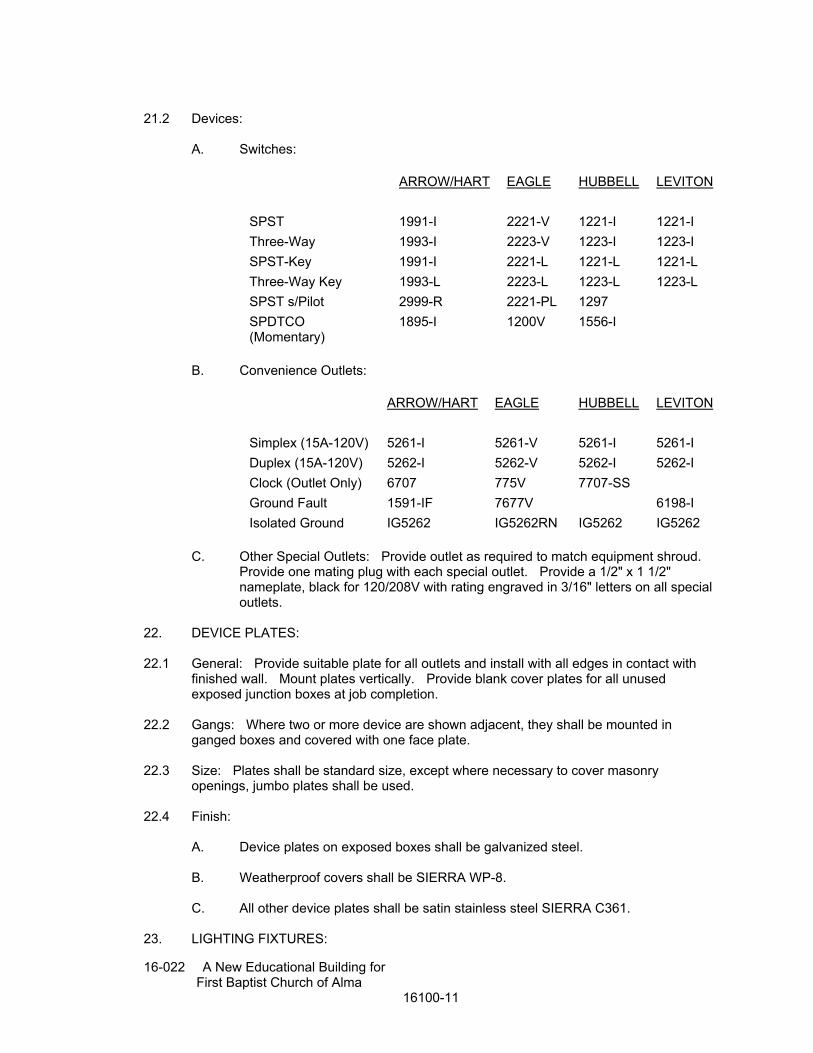
21.2 Devices:
A. Switches:
ARROW/HART EAGLE HUBBELL LEVITON
SPST 1991-I 2221-V 1221-I 1221-I
Three-Way 1993-I 2223-V 1223-I 1223-I
SPST-Key 1991-I 2221-L 1221-L 1221-L
Three-Way Key 1993-L 2223-L 1223-L 1223-L
SPST s/Pilot 2999-R 2221-PL 1297
SPDTCO (Momentary)
1895-I 1200V 1556-I
B. Convenience Outlets:
ARROW/HART EAGLE
HUBBELL LEVITON
Simplex (15A-120V) 5261-I 5261-V 5261-I 5261-I
Duplex (15A-120V) 5262-I 5262-V 5262-I 5262-I
Clock (Outlet Only) 6707 775V 7707-SS
Ground Fault 1591-IF 7677V 6198-I
Isolated Ground IG5262 IG5262RN IG5262 IG5262
C. Other Special Outlets: Provide outlet as required to match equipment shroud.
Provide one mating plug with each special outlet. Provide a 1/2" x 1 1/2" nameplate, black for 120/208V with rating engraved in 3/16" letters on all special outlets.
22. DEVICE PLATES: 22.1 General: Provide suitable plate for all outlets and install with all edges in contact with
finished wall. Mount plates vertically. Provide blank cover plates for all unused exposed junction boxes at job completion.
22.2 Gangs: Where two or more device are shown adjacent, they shall be mounted in
ganged boxes and covered with one face plate. 22.3 Size: Plates shall be standard size, except where necessary to cover masonry
openings, jumbo plates shall be used. 22.4 Finish:
A. Device plates on exposed boxes shall be galvanized steel. B. Weatherproof covers shall be SIERRA WP-8. C. All other device plates shall be satin stainless steel SIERRA C361.
23. LIGHTING FIXTURES:
16-022 A New Educational Building for First Baptist Church of Alma
16100-12
23.1 General: Provide lighting fixtures of types and sizes as indicated on drawings complete
with plaster frames, supports and mounting accessories. Fixtures shall be left clean at completion of project.
23.2 - not used 23.3 Suspension:
A. Grid Troffers: Omit hangers and fasten to inverted tees with holddown clips. B. Surface and recessed incandescent: For ceiling support systems with members
2' on center, use fixture support brackets supplied by manufacturer. Where no bracket is supplied by manufacturer and where span exceeds 2', provide two 1 5/8" x 7/8" x 12 ga. minimum channels spanning ceiling supports with 18 ga. stainless steel wire tiles.
C. Flanged troffers, surface fluorescent or recessed H.I.D.: Support from structural
system with two 3/8" threaded rods, unless otherwise noted. Use nut and locknut to secure fixture. For fixtures not connected with flexible conduit, the contractor shall verify exact location of fixture knock-out and wireway prior to roughing outlet box.
23.4 Structural System Attachments:
A. Poured-in-place concrete or precast solid masonry: Concrete expandable anchors unless otherwise noted.
B. Steel Bar Joints or Steel Beams: 1 5/8" x 3/4" x 12 ga. channel bolted to top
chords. Drill channel and secure threaded rods to channel with nut and locknut unless otherwise noted.
C. Along Bar Joist or Steel Beam Center Line: F&M Fig. 255, GRINNELL Fig. 88
or ELCEN Fig. 29 beam clamps unless otherwise noted. 23.5 Fixture Ceiling Compatibility: Fixture numbers scheduled are for general design only
(i.e. size, number of lamps, lens, etc.). Contractor is to verify type ceiling system (plaster, sheetrock, grid, spline, etc.) to be used and order appropriate fixtures complete with all necessary accessories as required for ceiling system.
24. LAMPS: 24.1 General: Provide for all fixtures. Fixtures shall be left clean and lamps burning at
completion of project. 24.2 Lamps: LED 3500k
16-022 A New Educational Building for First Baptist Church of Alma
16100-13
25. TELEPHONE CONDUIT SYSTEM: 25.1 General: Provide outlets and raceways at locations shown on the drawings. 25.2 Entrance: existing. 25.3 Backboard: 3/4" plywood. See 16100.15. 25.4 Wall Outlets: Flush boxes with blank plates. 25.5 Floor Outlets: Flush floor boxes with cover plates 25.6 Raceway: 3/4" conduit with pull cord to above ceiling and terminated with smooth
bushing. 26. COMPUTER DATA AND ALARM CONDUIT SYSTEM: 26.1 Provide outlets and raceways at locations shown on drawings. 26.2 Wall Outlets: Flush boxes with blank plates. 26.3 Floor Outlets: Flush floor boxes with cover plates. 26.4 Raceway: Conduits with sizes as shown. Minimum size for conduit shall be 1" unless
noted otherwise. 27. PANELBOARDS: 27.1 Section Includes:
A. Power Distribution Panelboards - Furnish and install distribution panelboards as specified herein and where shown on the associated drawings.
B. Lighting and Appliance Panelboards - Furnish and install lighting and appliance
panelboards as specified herein and where shown on the associated drawings. 27.2 Submittal and Record Documentation
A. Provide submittals for all panelboards. B. See Section 16100 for format and other information.
PART 2 PRODUCTS 27.3 Manufacturers
A. Shall be Square D Company
1. I-LINE - CLASS 2110 2. NQOD - CLASS 1630 3. NEHB - CLASS 1660

16-022 A New Educational Building for First Baptist Church of Alma
16100-14
B. Approved manufacturers are: General Electric, Westinghouse, or ITE Siemens. 27.4 Power Distribution Panelboards
A. I-LINE Circuit Breaker Distribution Panelboard
1. Interior
a. Shall be Square D I-LINE type rated 600 VAC or 250 VDC maximum. Continuous main current ratings as indicated on associated drawings not to exceed 1200 amperes maximum. Panelboard bus current ratings shall be determined by heat-rise tests conducted in accordance with UL 67.
b. Provide UL Listed short circuit current ratings (SCCR) as
indicated on the associated drawings not to exceed the lowest interrupting capacity rating of any circuit breaker installed with a maximum of 200,000 rms symmetrical amperes. Main lug and main breaker panelboards shall be suitable for use as Service Equipment when application requirements comply with UL 67 and NEC Articles 230-F and -G.
c. The panelboard interior shall have three flat bus bars stacked
and aligned vertically with glass reinforced polyester insulators laminated between phases. The molded polyester insulators shall support and provide phase isolation to the entire length of bus.
d. The bussing shall be fully rated with sequentially phased branch
distribution. Panelboard bussing rated 100 through 800 amperes shall be plated copper. The entire interleaved assembly shall be contained between two (2) U-shaped steel channels, permanently secured to a galvanized steel mounting pan by fasteners employing the use of a tamper-resistant warning label.
e. Interior trim shall be of dead-front construction to shield user
from all energized parts. Main circuit breakers through 800 amperes shall be vertically mounted. Main circuit breaker and main lug interiors shall be field convertible for top or bottom incoming feed.
f. Equipment ground bar shall be bonded. Ground bar shall be
copper. Solid neutral shall be equipped with a full capacity grounding strap for service entrance applications. Gutter-mounted neutral will not be acceptable.
g. Nameplates shall contain system information and catalog
number or factory order number. Interior wiring diagram, neutral wiring diagram, UL Listed label, and Short Circuit Current Rating shall be provided. Leveling provisions shall be provided for flush mounted applications.
2. Molded Case Circuit Breakers - Mains and Branches
a. Common Characteristics
16-022 A New Educational Building for First Baptist Church of Alma
16100-15
1) Circuit breakers shall be constructed using glass
reinforced polyester insulating material providing superior dielectric strength. Current-carrying components shall be completely isolated from the handle and the accessory mounting area.
2) Circuit breakers shall have an over-center, trip-free,
toggle operating mechanism which will provide quick-make, quick-break contact action. The circuit breaker shall have common tripping of all poles.
3) Circuit breakers shall have a push-to-trip button for
maintenance and testing purposes. 4) Circuit breaker escutcheon shall have international I/O
markings, in addition to standard ON/OFF markings. Circuit breaker handle accessories shall provide provisions for locking handle in the ON or OFF position.
5) Breaker faceplate shall indicate rated ampacity.
Breaker faceplate shall indicate UL and IEC certification standards with applicable voltage systems and corresponding AIR ratings.
6) Circuit breakers shall be factory sealed and shall have a
date code on the face of the circuit breaker. Poles shall be labeled with respective phase designations.
b. Thermal Magnetic Circuit Breakers
1) Circuit protective devices shall be Square D molded
case circuit breakers. Circuit breakers shall be standard interrupting construction. Ampere ratings shall be as shown on the drawings.
2) Circuit breakers shall have a permanent trip unit with thermal and magnetic trip elements in each pole. Thermal elements shall be factory calibrated to operate in a 40 C ambient environment. Thermal elements shall be ambient compensating above 40 C.
3) Two- and three-pole circuit breakers shall have an
internal common trip crossbar to provide simultaneous tripping. Circuit breaker frame sizes above 100 amperes shall have a single magnetic trip adjustment located on the front of the breaker which allows the user to simultaneously select the desired trip level of all poles.
3. Enclosures
a. Type 1 Boxes
1) Boxes shall be galvanized steel constructed in accordance with UL 50 requirements. Zinc-coated galvannealed steel will not be acceptable.
16-022 A New Educational Building for First Baptist Church of Alma
16100-16
2) Boxes shall have removable blank endwalls and interior mounting studs. Interior support bracket shall be provided for ease of interior installation.
3) Maximum enclosure dimensions shall be 42 in wide and
9.5 in deep.
b. Type 1 Trim Fronts
1) Trim front steel shall meet strength and rigidity requirements per UL 50 standards. Shall have an ANSI 49 medium gray enamel electrodeposited over cleaned phosphatized steel.
2) Trim front shall be 4-piece surface, 1-piece with door, or
hinged 1-piece with door, flush or surface mounted, as shown on drawings. Trim front door shall have rounded corners and edges free of burrs. A clear plastic directory card holder shall be mounted on the inside of the door.
3) Locks shall be cylindrical tumbler type with larger
enclosures requiring sliding vault locks with 3-point latching. All lock assemblies shall be keyed alike. Two (2) keys shall be provided with each lock.
c. Type 3R, 3S, 5, and 12
1) Enclosures shall be constructed in accordance with UL 50 requirements. Endwalls shall be welded and sealed. Enclosures shall be painted with ANSI 49 gray enamel electro-deposited over cleaned phosphatized steel.
2) All doors shall be gasketed and be equipped with a
tumbler type vault lock and two (2) additional trunk type latches. A clear plastic directory card holder shall be mounted on the inside of door. All lock assemblies shall be keyed alike. Two (2) keys shall be provided with each lock.
3) Maximum enclosure dimensions shall not exceed 42 in
wide and 12.95 in deep.
27.5 Lighting and Appliance Panelboard Type
A. NQOD:
1. Interior
a. Shall be type NQOD panelboard rated for 240 VAC/48 VDC maximum. Continuous main current ratings, as indicated on associated schedules, not to exceed 600 amperes maximum.
b. Minimum short circuit current rating: 10,000 in rms symmetrical
16-022 A New Educational Building for First Baptist Church of Alma
16100-17
amperes at 240 VAC. c. Provide one (1) continuous bus bar per phase. Each bus bar
shall have sequentially phased branch circuit connectors suitable for bolt-on branch circuit breakers. The bussing shall be fully rated. Panelboard bus current ratings shall be determined by heat-rise tests conducted in accordance with UL 67. Bussing rated 100-400 amperes shall be copper. Bussing rated for 600 amperes shall be copper as standard construction. Panelboards shall be suitable for use as Service Equipment when application requirements comply with UL 67 and NEC Articles 230-F and -G.
d. All current-carrying parts shall be insulated from ground and
phase-to-phase by Noryl high dielectric strength thermoplastic or equivalent.
e. Split solid neutral shall be plated and located in the mains
compartment up to 225 amperes so all incoming neutral cable may be of the same length.
f. Interior trim shall be of dead-front construction to shield user
from energized parts. Dead-front trim shall have pre-formed twist outs covering unused mounting space.
g. Nameplates shall contain system information and catalog
number or factory order number. Interior wiring diagram, neutral wiring diagram, UL Listed label and short circuit current rating shall be displayed on the interior or in a booklet format.
h. Interiors shall be field convertible for top or bottom incoming
feed. Main and sub-feed circuit breakers shall be vertically mounted. Main lug interiors up to 400 amperes shall be field convertible to main breaker. Interior leveling provisions shall be provided for flush mounted applications.
2. Main Circuit Breaker
a. Shall be Square D type circuit breakers. b. Main circuit breakers shall have an over-center, trip-free, toggle
mechanism which will provide quick-make, quick-break contact action. Circuit breakers shall have a permanent trip unit with thermal and magnetic trip elements in each pole. Each thermal element shall be true rms sensing and be factory calibrated to operate in a 40deg C ambient environment. Thermal elements shall be ambient compensating above 40deg C.
c. Two- and three-pole circuit breakers shall have common tripping
of all poles. Circuit breakers frame sizes above 100 amperes shall have a single magnetic trip adjustment located on the front of the circuit breaker which allows the user to simultaneously select the desired trip level of all poles. Circuit breakers shall have a push-to-trip button for maintenance and testing purposes.
d. Breaker handle and faceplate shall indicate rated ampacity.

16-022 A New Educational Building for First Baptist Church of Alma
16100-18
Standard construction circuit breakers shall be UL Listed for reverse connection without restrictive line or load markings.
e. Circuit breaker escutcheon shall have international I/O markings,
in addition to standard ON/OFF markings. Circuit breaker handle accessories shall provide provisions for locking handle in the ON or OFF position.
f. Lugs shall be UL Listed to accept solid or stranded copper
conductors. Lugs shall be suitable for 75deg C rated wire, sized according to the 75deg C temperature rating per NEC Table 310-16. Lug body shall be bolted in place; snap-in designs are not acceptable.
g. The circuit breakers shall be UL Listed for use with the following
accessories: Shunt Trip, Under Voltage Trip, Ground Fault Shunt Trip, Auxiliary Switch, Alarm Switch, Mechanical Lug Kits, and Compression Lug Kits.
3. Branch Circuit Breakers
a. Shall be Square D type circuit breakers. Circuit breakers shall
be UL Listed with amperage ratings, interrupting ratings, and number of poles as indicated on the panelboard schedules.
b. Molded case branch circuit breakers shall have bolt-on type bus
connectors. c. Circuit breakers shall have an over center toggle mechanism
which will provide quick-make, quick-break contact action. Circuit breakers shall have thermal and magnetic trip elements in each pole. Two- and three-pole circuit breakers shall have common tripping of all poles.
d. There shall be two forms of visible trip indication. The breaker
handle shall reside in a position between ON and OFF. In addition, there shall be a red VISI-TRIP® indicator appearing in the clear window of the circuit breaker housing.
e. The exposed face-plates of all branch circuit breakers shall be
flush with one another. f. Lugs shall be UL Listed to accept solid or stranded copper
conductors. Lugs shall be suitable for 75deg C rated wire, sized according to the 75deg C temperature rating per NEC Table 310-16. Branch circuit breakers rated 30 amperes and below shall be UL Listed to accept 60deg C rated wire.
g. Breakers shall be UL Listed for use with the following factory
installed accessories: Shunt Trip, Auxiliary Switch, Alarm Switch.
4. Enclosures
a. Type 1 Boxes
16-022 A New Educational Building for First Baptist Church of Alma
16100-19
1) Boxes shall be galvanized steel constructed in accordance with UL 50 requirements. Galvannealed steel will not be acceptable.
2) Boxes shall have removable endwalls with knockouts
located on one end. Boxes shall have welded interior mounting studs. Interior mounting brackets are not required.
3) Box width shall be 20 in or 14 in wide.
b. Type 1 Fronts
1) Front shall meet strength and rigidity requirements per UL 50 standards. Front shall have ANSI 49 gray enamel electrodeposited over cleaned phosphatized steel.
2) Fronts shall be 1-piece with door or hinged 1-piece with
door. Mounting shall be flush or surface as indicated on drawings.
3) Panelboards rated 225 amperes and below shall have
MONO- FLAT fronts with concealed door hinges and trim screws. Front shall not be removable with the door locked. Panelboards rated above 225 amperes shall have fronts with trim clamps and concealed door hinges. Front doors shall have rounded corners and edges shall be free of burrs.
4) Front shall have cylindrical tumbler type lock with catch
and spring-loaded stainless steel door pull. All lock assemblies shall be keyed alike. Two (2) keys shall be provided with each lock. A clear plastic directory card holder shall be mounted on the inside of door.
c. Type 3R, 5, and 12
1) Enclosures shall be constructed in accordance with UL 50 requirements. Enclosures shall be painted with ANSI 49 gray enamel electrodeposited over cleaned phosphatized steel.
2) All doors shall be gasketed and equipped with a tumbler
type vault lock. All lock assemblies shall be keyed alike. One (1) key shall be provided with each lock. A clear plastic directory card holder shall be mounted on the inside of door.
3) Maximum enclosure dimensions shall not exceed 20 in
wide and 6.5 in deep.
B. NEHB
1. Interior:
a. Shall be type NEHB panelboard rated for 480Y/277 VAC maximum. Continuous main current ratings as indicated on
16-022 A New Educational Building for First Baptist Church of Alma
16100-20
associated schedules, not to exceed 400 amperes maximum for main breaker or 600 amperes maximum for main lugs.
b. Minimum short circuit current rating: 14,000rms symmetrical
amperes at 480Y/277 VAC. c. Provide one (1) continuous bus bar per phase. Each bus bar
shall have sequentially phased branch circuit connectors suitable for bolt-on branch circuit breakers. The bussing shall be fully rated. Panelboard bus current ratings shall be determined by heat-rise tests conducted in accordance with UL 67. Bussing rated 100-600 amperes shall be copper as standard construction. Panelboards shall be suitable for use as Service Equipment when application requirements comply with UL 67 and NEC Articles 230-F and -G.
d. All current-carrying parts shall be insulated from ground and
phase-to-phase by Noryl high dielectric strength thermoplastic or equivalent.
e. Split solid neutral shall be plated and located in the mains
compartment up to 225 amperes so all incoming neutral cable may be of the same length.
f. Interior trim shall be of dead-front construction to shield user
from energized parts. Dead-front trim shall have pre-formed twistouts covering unused mounting space.
g. Nameplates shall contain system information, catalog number, or
factory order number. Interior wiring diagram, neutral wiring diagram, UL Listed label, and short circuit current rating shall be displayed on the interior or in a booklet format.
h. Interiors shall be field convertible for top or bottom incoming
feed. Main and sub-feed circuit breakers shall be vertically mounted. Main lug interiors up to 400 amperes shall be field convertible to main circuit breaker. Interior leveling provisions shall be provided for flush mounted applications.
2. Main Circuit Breaker
a. Shall be Square D type circuit breakers. b. Main circuit breakers shall have an overcenter, trip-free, toggle
mechanism which will provide quick-make, quick-break contact action. Circuit breakers shall have a permanent trip unit with thermal and magnetic trip elements in each pole. Each thermal element shall be true rms sensing and be factory calibrated to operate in a 40deg C ambient environment. Thermal elements shall be ambient compensating above 40deg C.
c. Two- and three-pole circuit breakers shall have common tripping
of all poles. Circuit breakers frame sizes above 100 amperes shall have a single magnetic trip adjustment located on the front of the circuit breaker which allows the user to simultaneously select the desired trip level of all poles. Circuit breakers shall

16-022 A New Educational Building for First Baptist Church of Alma
16100-21
have a push-to-trip button for maintenance and testing purposes. d. Breaker handle and faceplate shall indicate rated ampacity.
Standard construction circuit breakers shall be UL Listed for reverse connection without restrictive line or load markings.
e. Circuit breaker escutcheon shall have International I/O markings,
in addition to standard ON/OFF markings. Circuit breaker handle accessories shall provide provisions for locking handle in the ON or OFF position.
f. Lugs shall be UL Listed to accept solid or stranded copper
conductors. Lugs shall be suitable for 75deg C rated wire, sized according to the 75deg C temperature rating per NEC Table 310-16. Lug body shall be bolted in place; snap-in designs are not acceptable.
g. The circuit breakers shall be UL Listed for use with the following
accessories: Shunt Trip, Under Voltage Trip, Ground Fault Shunt Trip, Auxiliary Switch, Alarm Switch, Mechanical Lug Kits, and Compression Lug Kits.
3. Branch Circuit Breakers
a. Shall be Square D type circuit breakers. Circuit breakers shall be UL Listed with amperage ratings, interrupting ratings, and number of poles as indicated on the panelboard schedules.
b. Molded case branch circuit breakers shall have bolt-on bus
connectors. c. Circuit breakers shall have an overcenter toggle mechanism
which will provide quick-make, quick-break contact action. Circuit breakers shall have thermal and magnetic trip elements in each pole. Two- and three- pole circuit breakers shall have common tripping of all poles.
d. There shall be two forms of visible trip indication. The breaker
handle shall reside in a position between ON and OFF. In addition, there shall be a red VISI-TRIP® indicator appearing in the clear window of the circuit breaker housing.
e. The exposed faceplates of all branch circuit breakers shall be
flush with one another. f. Lugs shall be UL Listed to accept solid or stranded copper
conductors. Lugs shall be suitable for 75deg C rated wire, sized according to the 75deg C temperature rating per NEC Table 310-16. [Branch breakers rated 30 amperes and below shall be UL Listed to accept 60deg C rated wire.
g. Breakers shall be UL Listed for use with the following factory
installed accessories: Shunt Trip, Auxiliary Switch, Alarm Switch.

16-022 A New Educational Building for First Baptist Church of Alma
16100-22
4. Enclosures
a. Type 1 Boxes
1) Boxes shall be galvanized steel constructed in accordance with UL 50 requirements. Galvannealed steel will not be acceptable.
2) Boxes shall have removable endwalls with knockouts
located on one end. Boxes shall have welded interior mounting studs. Interior mounting brackets are not required.
3) Box width shall be 20 in wide.
b. Type 1 Fronts
1) Front shall meet strength and rigidity requirements per UL 50 standards. Front shall have ANSI 49 gray enamel electrodeposited over cleaned phosphatized steel.
2) Fronts shall be 1-piece with door or hinged 1-piece with
door. Mounting shall be flush or surface as indicated on associated drawings.
3) Panelboards rated 225 amperes and below shall have
MONO-FLAT fronts with concealed door hinges and trim screws. Front shall not be removable with the door locked. Panelboards rated above 225 amperes shall have fronts with trim clamps and concealed door hinges. Front doors shall have rounded corners; edges shall be free of burrs.
4) Front shall have cylindrical tumbler type lock with catch and spring-loaded stainless steel door pull. All lock assemblies shall be keyed alike. Two (2) keys shall be provided with each lock. A clear plastic directory card holder shall be mounted on the inside of door.
c. Type 3R, 5, and 12
1) Enclosures shall be constructed in accordance with UL 50 requirements. Enclosures shall be painted with ANSI 49 gray enamel electrodeposited over cleaned phosphatized steel.
2) All doors shall be gasketed and equipped with a tumbler
type vault lock. All lock assemblies shall be keyed alike. One (1) key shall be provided with each lock. A clear plastic directory card holder shall be mounted on the inside of door.
3) Maximum enclosure dimensions shall not exceed 21 in
wide and 6.5 in deep.

16-022 A New Educational Building for First Baptist Church of Alma
16100-23
PART 3 EXECUTION 27.6 Installation:
A. Install panelboards in accordance with manufacturer's written instructions, NEMA PB 1.1 and NEC standards.
B. Provide 3/4-inch painted plywood backboard, with iron angle frame, for mounting
of all surface mounted panelboards. Also provide 4-inch concrete pad at floor of sufficient size to protect all bottom-entry conduits. For adjacent panelboards, provide continuous pad between panels. Smooth finish entire pad.
C. Label circuit breakers in panelboards consecutively down left side from 1 to 21
(for 42-pole panel, or half of breakers for smaller panel.), and from 22 to 42 down the right side of the panel, such to avoid connecting two consecutive circuits to the same electrical phase.
D. Provide a typed circuit directory to be installed in the slot provided for the
purpose. Directory shall indicate the type of load connected to each respective circuit breaker, as well as the location of the connected load, i.e.: “Receptacles in spaces 112 and 113", “ACU-3", or “Parking lot lights”, as appropriate. Spare circuits shall be labeled lightly in pencil.
27.7 Field Quality Control:
A. Inspect complete installation for physical damage, proper alignment, anchorage, and grounding.
B. Measure steady state load currents at each panelboard feeder; rearrange circuits
in the panelboard to balance the phase loads within 20% of each other. Maintain proper phasing for multi-wire branch circuits.
C. Check tightness of bolted connections and circuit breaker connections using
calibrated torque wrench or torque screwdriver per manufacturer's written specifications.
28. Time Clocks: Time clocks shall be 24-hour astronomical, 5-day/2-day with skip-a-day function, rated at
30 amps. Tork ‘Z’ Series (7200Z).
END OF SECTION