section 2 - periodic maintenance/tune-up · section 2 - periodic maintenance/tune-up table of ......
TRANSCRIPT

2-1
2
SECTION 2 - PERIODIC MAINTENANCE/TUNE-UP
TABLE OFCONTENTS
Periodic Maintenance Chart.................................... 2-2Lubrication Points.................................................... 2-3Battery..................................................................... 2-3Fuses ...................................................................... 2-4Air Cleaner .............................................................. 2-4Valve/Tappet Clearance ......................................... 2-6Tappet Shim Selection Table (Exhaust) .................. 2-9Tappet Shim Selection Table (Intake).................... 2-10Testing Engine Compression ................................ 2-11Spark Plug............................................................. 2-11Muffler/Spark Arrester ........................................... 2-12Gas/Vent Hoses .................................................... 2-12Adjusting Throttle Cable ........................................ 2-12Adjusting Engine RPM (Idle) ................................. 2-13Engine/Transmission Oil - Filter............................. 2-13Adjusting Clutch Lever Cable ................................ 2-14Tires ...................................................................... 2-15Steering Components ........................................... 2-15Suspension/Shock Absorbers/Bushings ............... 2-15Nuts/Bolts/Cap Screws.......................................... 2-15Headlight/Taillight-Brakelight ................................. 2-15Switches................................................................ 2-17Indicator Lights...................................................... 2-17Frame/Welds ......................................................... 2-17Electrical Connections........................................... 2-17Hydraulic/Parking Brake Systems ......................... 2-17Burnishing Brake Pads.......................................... 2-22Coolant.................................................................. 2-22Drive Chain ........................................................... 2-22
For Arctic Cat Discount Parts Call 606-678-9623 or 606-561-4983
www.mymowerparts.com

2-2
Periodic Maintenance Chart
* Service/Inspect more frequently when operating in adverse conditions.
ItemInitial Service After Break-In
(First Mo)
EveryDay
Every Month Every 3 Months
Every 6 Months
Every Year As Needed
Battery Charge CFuse I RAir Filter/Drain Tube I I C* RValve/Tappet Clearance I I AEngine Compression ISpark Plug I I R (18 Mo)Muffler/Spark Arrester C RGas/Vent Hoses I I R (2 Yrs)Gas Tank Valve I CThrottle Cable I I C-L A-RCarb Float Chamber D*Engine RPM (Idle) I I AEngine-Transmission Oil
LevelI A
Engine-Transmission Oil/Filter
R R* R
Oil Strainer I I CDrive Chain I I A RClutch I l ATires/Air Pressure I I RSteering Components I I RCoolant Hoses I l R (4 yrs)Suspension (Ball joint and
tie rod boots, tie rods, and shock mounts)
I l* R
Nuts/Cap Screws/Screws I I AOil Lines I IHeadlight/Taillight-
BrakelightI I R
Switches I I RReverse Selector Cable I I A-LChoke Cable I I C-L RHandlebar Grips I RHandlebars I I RIndicator Lights I I RFrame/Welds I I lElectrical Connections l CComplete Brake Systems
(Hydraulic & Parking)I I C L-R
Brake Pads I I* RBrake Fluid I I R (2 Yrs)Brake Hoses I I R (4 Yrs)Brake Cable (Parking) I-ACoolant/Cooling System I I R (2 Yrs)
A = Adjust I = InspectC = Clean L = LubricateD = Drain R = Replace
2-3
2
Lubrication Points
It is advisable to lubricate certain components periodi-cally to ensure free movement. Apply light oil to thecomponents using the following list as reference.
A. Throttle Lever Pivot/Cable Ends
B. Brake Lever Pivot
C. Parking Brake Cable Ends
D. Choke Cable Upper End
E. Reverse Selector Cable End
F. Idle RPM Screw (Carburetor)
G. Rear Brake Pedal Pivot
Battery
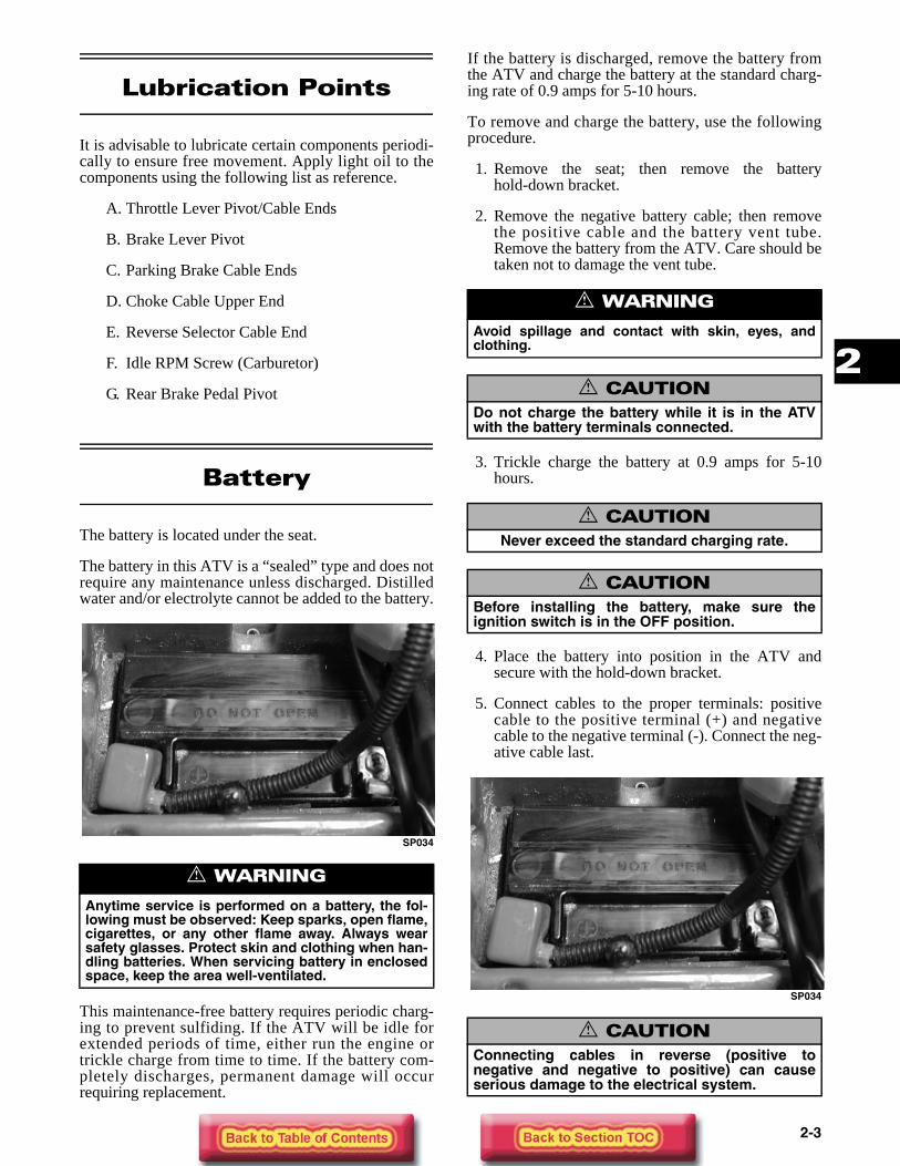
The battery is located under the seat.
The battery in this ATV is a “sealed” type and does notrequire any maintenance unless discharged. Distilledwater and/or electrolyte cannot be added to the battery.
SP034
This maintenance-free battery requires periodic charg-ing to prevent sulfiding. If the ATV will be idle forextended periods of time, either run the engine ortrickle charge from time to time. If the battery com-pletely discharges, permanent damage will occurrequiring replacement.
If the battery is discharged, remove the battery fromthe ATV and charge the battery at the standard charg-ing rate of 0.9 amps for 5-10 hours.
To remove and charge the battery, use the followingprocedure.
1. Remove the seat; then remove the batteryhold-down bracket.
2. Remove the negative battery cable; then removethe positive cable and the battery vent tube.Remove the battery from the ATV. Care should betaken not to damage the vent tube.
3. Trickle charge the battery at 0.9 amps for 5-10hours.
4. Place the battery into position in the ATV andsecure with the hold-down bracket.
5. Connect cables to the proper terminals: positivecable to the positive terminal (+) and negativecable to the negative terminal (-). Connect the neg-ative cable last.
SP034
! WARNING
Anytime service is performed on a battery, the fol-lowing must be observed: Keep sparks, open flame,cigarettes, or any other flame away. Always wearsafety glasses. Protect skin and clothing when han-dling batteries. When servicing battery in enclosedspace, keep the area well-ventilated.
! WARNING
Avoid spillage and contact with skin, eyes, andclothing.
! CAUTIONDo not charge the battery while it is in the ATVwith the battery terminals connected.
! CAUTIONNever exceed the standard charging rate.
! CAUTIONBefore installing the battery, make sure theignition switch is in the OFF position.
! CAUTIONConnecting cables in reverse (positive tonegative and negative to positive) can causeserious damage to the electrical system.

2-4
6. Install the seat making sure it locks securely.
FUSES
There is one 20 amp fuse and one spare 20 amp fuselocated adjacent to the battery on the starter relay.
If there is any type of electrical system failure, alwayscheck the fuse first.
SP032A
Air Cleaner
The air filter inside the air cleaner must be kept cleanto provide good engine power and gas mileage. If theATV is used under normal conditions, service the filterat the intervals specified. If operated in dusty, wet, ormuddy conditions, inspect and service the filter morefrequently.
CLEANING AND INSPECTING FILTER
1. Remove the seat.
2. Unseat the two retaining clips securing the aircleaner housing cover; then remove the cover.
SP014A
3. Remove the screw securing the air filter stopperand set aside; then remove the filter assembly.
SP012
4. Remove the foam wrap from the filter frame.
SP013
5. Fill a wash pan larger than the filter with anon-flammable cleaning solvent; then dip the filterin the solvent and wash it.
NOTE: Foam Filter Cleaner (p/n 0436-194) andFoam Filter Oil (p/n 0436-195) are available fromArctic Cat.
6. Dry the filter.
! CAUTIONAlways replace a blown fuse with a fuse of thesame type and rating.
! CAUTIONFailure to inspect the air filter frequently if theATV is used in dusty, wet, or muddy conditionscan damage the ATV engine.

2-5
2
7. Put the filter in a plastic bag; then pour in air filteroil and work the filter.
8. Clean any dirt or debris from inside the air cleaner.Be sure no dirt enters the carburetor.
9. Place the filter in the air filter housing making sureit is properly in position and properly seated andsecure with the stopper and screw.
10. Install the air filter housing cover and secure withthe retaining clips; then install the seat makingsure the seat is properly secured.
CHECKING/DRAINING DRAIN TUBE
1. Periodically check the drain tube for gasoline oroil accumulation. If noticed, remove the drain tubecap from beneath the front housing, drain the gas-oline or oil into a suitable container, and installand secure the tube cap.
2. Inspect one-way drain tube beneath the main hous-ing for debris and for proper sealing.
SP119
REMOVING
1. Remove the seat.
2. Unseat the two retaining clips securing the aircleaner housing; then remove the cover.
SP014A
3. Remove the screw securing the air filter stopperand set aside; then remove the air filter.
SP012
4. Loosen the clamp securing the air cleaner to theinlet duct; then loosen the clamp securing the aircleaner to the outlet tube.
5. Remove the cap screws securing the air cleaner tothe frame.
6. Remove the air cleaner from the frame.
INSTALLING
0739-212
1. Place the air cleaner into the frame.
2. Install the cap screws securing the air cleaner tothe frame.
! CAUTIONA torn air filter can cause damage to the ATVengine. Dirt and dust may get inside the engine ifthe element is torn. Carefully examine theelement for tears before and after cleaning it.Replace the element with a new one if it is torn.
KEY1. Air Cleaner Assy2. Filter3. Holder4. Stopper5. Screw6. Outlet Tube7. Elbow Fitting8. Breather Plug9. Clip
10. Clamp11. Clamp12. Flame Trap13. Cover14. Gasket15. Inlet Joint16. Inlet Duct17. Clamp18. Cap Screw19. Cap Screw

2-6
3. Install the outlet tube onto the air cleaner; thentighten the clamp securely.
4. Install the inlet duct onto the air cleaner; thentighten the clamp securely.
5. Install the filter with foam wrap into the aircleaner; then tighten the filter stopper screwsecurely.
SP012
6. Place the air cleaner cover into position and securewith the retaining clips.
SP014A
7. Install the seat making sure the seat is properlysecured.
Valve/TappetClearance
CHECKING
To check and adjust valve/tappet clearance, use thefollowing procedure.
1. Remove the seat, gas tank cover, and body.
2. Turn the fuel valve to the “ON” position; thenremove the gas tank.
3. Disconnect the engine oil hose (3) and the engineoil breather hose (4); then remove the spark plug.
SP120
4. Remove the three large Allen-head cap screwssecuring the valve cover; then remove the valvecover accounting for the two camshaft end plugsand the valve cover gasket.
SP121
NOTE: The valve/tappet clearance specificationis different for intake and exhaust valves. Theclearance should only be checked when theengine is cold (room temperature).
NOTE: Valve/tappet clearance adjustment mustbe checked and adjusted in accordance with theperiodic maintenance chart or anytime valvemechanism components are removed and rein-stalled.
5. Remove the valve timing inspection plug (1) andthe generator cover cap (2); then rotate the crank-shaft with a socket wrench to top-dead-center(TDC) on the compression stroke. The “T” line onthe alternator rotor is aligned with the trianglemark on the alternator cover.

2-7
2
SP122
SP123
NOTE: The camshaft lobes must be in position(A) in order to check valve/tappet clearance.
SP124
6. Insert a feeler gauge between the tappet and thecamshaft. The clearance must be within specifica-tions.
SP125
If the clearance is out of specifications, adjust theclearance using the following procedure.
ADJUSTING
The clearance is adjusted by replacing the existing tap-pet shim with a thicker or thinner shim.
1. Remove the camshaft corresponding to theout-of-tolerance tappet. See Section 3.
2. Using a magnet, remove the tappet and shim; thencheck the numbers printed on the tappet shim.
ATV2151
NOTE: These numbers indicate the thickness ofthe tappet shim as illustrated.
3. Select a replacement tappet shim that will providethe proper clearance.
NOTE: Tappet shims are available in 25 sizesfrom 2.30-3.50 mm (0.09-0.14 in.) in 0.05 mm (0.002in.) increments.
4. Install the selected shim at the valve stem with thenumbers facing the tappet. Be sure to measure theshim with a micrometer to ensure it is the propersize. Refer to the tappet shim selection table fordetails.
NOTE: Apply molybdenum oil solution to the topand bottom of the tappet shim. Make sure that thenumbered side is directed toward the tappet.
5. Install the camshaft (see Section 3).

2-8
6. Rotate the crankshaft through two full revolutionsto ensure that all excess oil is squeezed from thevalve/tappet clearance to make sure it is withinspecifications.
7. Apply Three Bond Sealant (p/n 0636-070) to thecamshaft end caps of the valve cover gasket; theninstall the valve cover.
8. Tighten the valve cover cap screws to specifica-tions.
9. Install the spark plug and tighten to specifications;then install the timing inspection plug.

2-9
2
ATV2152

2-10
ATV2153

2-11
2
Testing Engine Compression
To test engine compression, use the following proce-dure.
1. Remove the high tension lead from the spark plug.
2. Using compressed air, blow any debris fromaround the spark plug.
3. Remove the spark plug; then attach the high ten-sion lead to the plug and ground the plug on thecylinder head well away from the spark plug hole.
4. Attach the Compression Gauge (p/n 0444-096).
NOTE: The engine must be warm and the batterymust be fully charged for this test.
5. While holding the throttle lever in the full-openposition, crank the engine over with the electricstarter until the gauge shows a peak reading (fiveto 10 compression strokes). The compressionshould be 10.0 kg/cm2 (142 psi).
6. If compression is abnormally low, inspect thefollowing items.
A. Verify starter cranks engine over at normalcranking speed.
B. Gauge is functioning properly.
C. Throttle lever in the full-open position.
D. Valve/tappet clearance correct.
E. Valve bent or burned.
F. Valve seat burned.
NOTE: To service valves, see Section 3.
7. Pour 29.5 ml (1 fl oz) of oil into the spark plughole, reattach the gauge, and retest compression.
8. If compression is now evident, service the pistonrings (see Section 3).
Spark Plug
A light brown insulator indicates that the plug is cor-rect. A white or dark insulator indicates that the enginemay need to be serviced or the carburetor may need tobe adjusted. To maintain a hot, strong spark, keep theplug free of carbon.
ATV-0051
Adjust the gap to 0.7 - 0.8 mm (0.028 - 0.032 in.). Usea feeler gauge to check the gap.
ATV0052B
When installing the spark plug, tighten to specifica-tions.
! WARNING
Always wear safety glasses when using com-pressed air.
! CAUTIONBefore removing the spark plug, be sure to cleanthe area around the spark plug. Dirt could enterengine when removing or installing the sparkplug.

2-12
Muffler/Spark Arrester
The muffler has a spark arrester which must be period-ically cleaned. At the intervals shown in the PeriodicMaintenance Chart, clean the spark arrester using thefollowing procedure.
1. Remove the three Allen-head cap screws securingthe spark arrester to the muffler; then remove thespark arrester.
SP001
2. Use a wire brush to remove carbon deposits fromthe arrester taking care not to damage the screen.
SP041
3. Check the arrester screen for holes or tears andreplace components as necessary.
4. Install the spark arrester and three cap screws andtighten securely.
Gas/Vent Hoses
Replace the gas hose every two years. Damage fromaging may not always be visible. Do not bend orobstruct the routing of the carburetor vent hose. Makecertain that the vent hose is securely connected to thecarburetor and the opposite end is always open.
Adjusting Throttle Cable
To adjust the throttle cable free-play, follow this pro-cedure.
1. Slide the rubber boot away; then loosen the jamnut from the throttle cable adjuster.
AL611D
2. Slide the rubber boot away and turn the adjusteruntil the throttle cable has proper free-play of 3-6mm (1/8 - 1/4 in.) at the lever.
ATV-0047
3. Tighten the jam nut against the throttle cableadjuster securely; then slide the rubber boot overthe adjuster.
! WARNING
Wait until the muffler cools to avoid burns.

2-13
2
Adjusting Engine RPM (Idle)
To properly adjust the idle RPM, a tachometer is nec-essary. To adjust idle RPM, use the following proce-dure.
1. With the transmission in neutral, start the engineand warm it up to normal operating temperature.
2. Turn the idle adjustment screw (on the left side ofthe carburetor) clockwise one turn past the recom-mended RPM setting; then turn it counterclock-wise to 1250-1350 RPM.
SP008A
Engine/TransmissionOil - Filter
OIL - FILTER
Change the engine oil and oil filter at the scheduledintervals. The engine should always be warm when theoil is changed so the oil will drain easily and com-pletely.
1. Park the ATV on level ground.
2. Loosen the oil level stick enough to allow air tovent the tank.
SP016A
3. Place drain pans under the oil tank drain plug (1)and the crankcase drain plug (2); then remove theplugs and drain the oil.
ATV2027
ATV2028
4. Remove the cap screws securing the filter cover.
5. Remove the filter cover (3); then pull out the oilfilter element (4) and properly discard. Removeand properly discard the O-ring from the filtercover.
! WARNING
Adjust the idle to the correct RPM. Make sure theengine is at normal operating temperature beforeadjusting the idle RPM.

2-14
ATV2029
NOTE: Clean up any excess oil after removingthe filter.
ATV2030
6. Apply oil to a new cover O-ring and check tomake sure it is positioned correctly in the cover.With the open end of the filter element directedtoward the center of the engine, slide the elementinto position.
0739-215
7. Place the filter cover in position with the trianglemark up and secure with the cap screws. Tightensecurely.
8. Install the crankcase drain plug and tighten tospecifications; then install the oil tank drain plugand tighten to specifications.
9. Pour the recommended type and quantity of oilinto the oil level stick hole; then start the engine(while the ATV is outside on level ground) andallow it to idle for a few minutes.
10. Turn the engine off and wait approximately oneminute. Recheck the oil level with the oil levelstick. The oil level should be between the upperand lower crosshatch marks on the level stick.Adjust oil level as necessary.
ATV2020A
11. Inspect the area around the drain plugs and oil fil-ter for leaks.
Adjusting Clutch Lever Cable
To adjust the cable, use the following procedure.
1. Pull rubber protective boot away from the cableadjusters.
2. Loosen the lock nut; then turn the adjuster toobtain 10-15 mm (0.4-0.6 in.) free-play measuredat point (A).
! CAUTIONIf the oil filter element is inserted backwards,engine damage will occur due to lack of oil flow.
KEY1. Oil Pump Assy2. Driven Gear3. Pin4. Washer5. Circlip6. Cap Screw7. Rotor Set8. Strainer9. Cap Screw
10. Oil Filter11. O-Ring12. Oil Filter Cover13. O-Ring14. Spring15. Cap Screw16. Spring17. Ball18. Oil Check-Valve Seat19. Gear20. Shaft21. Circlip
! CAUTIONAny oil used in place of the recommended oilcould cause serious engine damage. Do not useoils which contain graphite or molybdenumadditives. These oils can adversely affect clutchoperation. Also, not recommended are racing,vegetable, non-detergent, and castor-based oils.

2-15
2
SP126
Tires
TIRE SIZES
The ATV is equipped with low-pressure tubeless tiresof the size and type listed. Do not under any circum-stances substitute tires of a different type or size.
TIRE INFLATION PRESSURE
Front and rear tire inflation pressure should be at rec-ommended specifications.
A low-pressure gauge is provided in the tool kit tomeasure the air pressure in the tires. Check the airpressure in all tires before each use of the ATV.
Steering Components
The following steering components should beinspected periodically to ensure safe and proper opera-tion.
A. Handlebar grips not worn, broken, or loose.B. Handlebar not bent, cracked, and has equal and
complete full-left and full-right capability.C. Steering post bearing assembly/bearing hous-
ing not broken, worn, or binding.D. Ball joints not worn, cracked, or damaged.E. Tie rods not bent or cracked.F. Knuckles not worn, cracked, or damaged.G. Cotter pins not damaged or missing.
Suspension/Shock Absorbers/Bushings
The following suspension system components shouldbe inspected periodically to ensure proper operation.
A. Shock absorber rods bent, pitted, or damaged.B. Rubber damper cracked, broken, or missing.C. Shock absorber body damaged, punctured, or
leaking.D. Shock absorber eyelets broken, bent, or
cracked.E. Shock absorber eyelet bushings worn, deter-
iorated, cracked, or missing.F. Shock absorber spring broken or sagging.
Nuts/Bolts/Cap Screws
Tighten all nuts, bolts, and cap screws. Make sure riv-ets holding components together are tight. Replace allloose rivets. Care must be taken that all calibratednuts, bolts, and cap screws are tightened to specifica-tions. For proper torque values, see Section 10.
Headlight/Taillight- Brakelight
Each time the ATV is used, lights should be checkedfor proper function. Rotate the ignition switch to thelights position; the headlights and taillight should illu-minate. Test the brakelight by compressing the brakelever. The brakelight should illuminate.
HEADLIGHT
NOTE: The bulb portion of the headlight is frag-ile. HANDLE WITH CARE. When replacing theheadlight bulb, do not touch the glass portion ofthe bulb. If the glass is touched, it must be cleanedwith a dry cloth before installing. Skin oil residueon the bulb will shorten the life of the bulb.
To replace the headlight bulb, use the following proce-dure.
! WARNING
Always use the size and type of tires specified.Always maintain proper tire inflation pressure.
! WARNING
Do not attempt to remove the bulb when it is hot.Severe burns may result.

2-16
1. Turn the bulb counterclockwise; then remove fromthe reflector housing.
2. Disconnect the two-wire connector from the bulb;then connect the new bulb to the connector.
3. Install the bulb into the reflector housing and turnthe bulb clockwise to lock.
TAILLIGHT-BRAKELIGHT
To replace the taillight-brakelight bulb, use the follow-ing procedure.
1. Twist the socket counterclockwise to remove itfrom the the taillight housing.
SP089
2. Pull the bulb straight out of the socket; then installthe new bulb.
SP085
3. Install the socket in the taillight housing by push-ing in and turning clockwise.
CHECKING/ADJUSTING HEADLIGHT AIM
The headlights can be adjusted vertically and horizon-tally. The geometric center of the HIGH beam lightzone is to be used for vertical and horizontal aiming.
1. Position the ATV on a level floor so the headlightsare approximately 6.1 m (20 ft) from an aimingsurface (wall or similar aiming surface).
NOTE: There should be an average operatingload on the ATV when adjusting the headlight aim.
2. Measure the distance from the floor to themid-point of each headlight.
3. Using the measurements obtained in step 2, makehorizontal marks on the aiming surface.
4. Make vertical marks which intersect the horizontalmarks on the aiming surface directly in front of theheadlights.
5. Switch on the lights. Make sure the HIGH beam ison. DO NOT USE LOW BEAM.
6. Observe each headlight beam aim. Proper aim iswhen the most intense beam is centered on the ver-tical mark 5 cm (2 in.) below the horizontal markon the aiming surface.
ATV2051B
7. Adjust each headlight until correct aim isobtained.
A. Horizontal — Loosen nut (A) and adjust forproper aiming. Tighten the nut securely.
B. Vertical— Loosen nut (B) and adjust for properaiming. Tighten the nut securely.
SP095A
! CAUTIONTighten the lens cover screws only until they aresnug.

2-17
2
SP094A
Switches
Each time the ATV is used, switches should bechecked for proper operation. Use the following listfor reference.
A. Ignition switch — engine will start.B. Emergency stop switch — engine will stop.C. Reverse switch — reverse indicator light
illuminates.D. Hi/Lo switch — headlight beam bright and
dim.E. Brake switches — rear brakelight illuminates.F. Neutral switch — neutral indicator light
illuminates when transmission is in neutral.
Indicator Lights
Each time the ATV is used, the lights should bechecked for proper function. Use the following for ref-erence.
ATV2007
1. Reverse Indicator — A red light will illuminatewhen the transmission is shifted into reverse gear.The light will go off when shifted out of reverse.
2. Neutral Indicator — A green light will illuminatewhen the transmission is in neutral and the ignitionswitch is on. The light will go out when shiftedinto any gear other than neutral.
3. Temperature Indicator — A red light will illu-minate if the engine overheats. The light should beoff during normal operation.
NOTE: High engine RPM, low vehicle speed, orheavy load can raise engine temperature. Decreas-ing engine RPM, reducing load, and selecting anappropriate transmission gear can lower the tem-perature.
NOTE: Debris between the cooling fins of theradiator can reduce cooling capability. Using ahose, pressure-wash the radiator to remove anydebris preventing air flow.
Frame/Welds
The frame and welds should be checked periodicallyfor damage, bends, cracks, deterioration, broken com-ponents, and missing components. If replacement orrepair constitutes removal, see Section 8.
Electrical Connections
The electrical connections should be checked periodi-cally for proper function. In case of an electrical fail-ure, check fuse, connections (for tightness, corrosion,damage), and/or bulbs. If an electrical componentneeds to be tested for proper function, see Section 5.
Hydraulic/ParkingBrake Systems
CHECKING/BLEEDING
The hydraulic brake systems have been filled and bledat the factory. To check and/or bleed a hydraulic brakesystem, use the following procedure.
! CAUTIONContinued operation of the ATV with high enginetemperature may result in engine damage orpremature wear.

2-18
1. With the front brake master cylinder in a levelposition, check the fluid level in the reservoir. Ifthe level in the reservoir is not visible in the sightglass, add DOT 4 brake fluid.
ATV2037
2. Compress the brake lever several times to checkfor a firm brake. If the brake is not firm, the frontbrake system must be bled.
3. Remove the rear brake reservior cap. If the level inthe reservoir is not above the mark, add DOT 4brake fluid.
SP111A
SP112A
4. Depress the brake pedal several times to check fora firm pedal. If the pedal is not firm, the rear brakesystem must be bled.
ATV2009
5. To bleed the front brake system, use the followingprocedure.
A. Remove the cover and fill the reservoir withDOT 4 Hi-Temp Brake Fluid (p/n 1639-799).
SP028
B. Install and secure the cover; then slowlycompress the brake lever several times.
C. Remove the protective cap, install one end of aclear hose onto one FRONT bleeder screw, anddirect the other end into a container; then whileholding slight pressure on the brake lever, openthe bleeder screw and watch for air bubbles.Close the bleeder screw before releasing thebrake lever. Repeat this procedure until no airbubbles are present.
AF637D

2-19
2
730-434B
NOTE: During the bleeding procedure, watch thereservoir sight glass very closely to make surethere is always a sufficient amount of brake fluid.Failure to maintain a sufficient amount of fluid inthe reservoir will result in air in the system.
D. Repeat step C until no air bubbles are observedin the bleeder line. Close the bleeder screw andtighten.
E. Perform steps B,C, and D on the other FRONTbleeder screw repeating step C until no airbubbles are observed in the bleeder line. Makesure that the brake lever is firm.
NOTE: If the brake lever is still not firm, it may benecessary to do the entire front brake bleedingprocedure over.
6. To bleed the rear brake system, use the followingprocedure.
A. Remove the rear brake reservoir cap and fill thereservoir with DOT 4 Hi-Temp Brake Fluid(p/n 1639-799).
B. Install and tighten the cover; then depress thebrake pedal several times.
C. Remove the protective cap, install one end of aclear hose on the REAR bleeder screw, anddirect the other end into a container; then whileholding slight pressure on the brake pedal, openthe bleeder screw and watch for air bubbles.Close the bleeder screw before releasing thebrake pedal. Repeat this procedure until no airbubbles are present.
D. Repeat step C until the brake pedal is firm.
7. Carefully inspect the hydraulic brake hoses forcracks or other damage. If found, the brake hosesmust be replaced.
INSPECTING HOSES
Carefully inspect the hydraulic brake hoses for cracksor other damage. If found, the brake hoses must bereplaced.
MEASURING/REPLACING FRONT BRAKE PADS
The clearance between the brake pads and brake discsis adjusted automatically as the brake pads wear. Theonly maintenance that is required is replacement of thebrake pads when they show excessive wear. Check thethickness of each of the brake pads as follows.
1. Remove the front wheels.
2. Measure the thickness of each brake pad.
AF739DB
3. If thickness of any brake pad is less than 2.0 mm(0.078 in.), all brake pads must be replaced.
NOTE: The brake pads should be replaced as acomplete set.
4. To replace the brake pads, use the following pro-cedure.
A. Remove the caliper mounting cap screws (1)and the brake pad mounting pins (2); thenremove the brake pads. Account for the shims.
SP127
NOTE: Do not compress the brake lever after thebrake pads are removed.
NOTE: Inspect the brake pad mounting pins (2)for wear. If excessive wear is found, the pins mutbe replaced.
! CAUTIONThis hydraulic brake system is designed to usehigh-temperature DOT 4 brake fluid only. If brakefluid must be added, care must be taken as brakefluid is very corrosive to painted surfaces.

2-20
NOTE: The shim must be installed on the pistonside brake pad.
SP128
NOTE: Make sure the detent of the brake pad isfitted to the recess on the brake caliper bracket.
SP129
B. Install the new brake pads; then tighten thebrake pad mounting pins and the brake calipermounting cap screws to specifications.
NOTE: After replacing the brake pads, compressthe brake lever several times to check for properbrake operation; then check the brake fluid level.
C. Install the wheels and tighten to specificationsusing a crisscross pattern.
SP018A
5. Burnish the brake pads (see Burnishing BrakePads in this section).
MEASURING/REPLACING REAR BRAKE PADS
1. Release the parking brake, if applied; then removetwo cap screws securing the brake caliper assem-bly to the rear housing.
SP061C
NOTE: Do not depress the brake pedal as thiswill push the piston out spilling brake fluid. Therear brake system will have to be refilled and bledif this occurs.
2. Bend down the tabs on the washer and remove thebrake pad mounting pins; then remove the brakepads.
SP114A
SP116
3. Inspect the pads for gouges, chips, or wear.
4. Inspect the disc for gouges, grooves, cracks, andwarpage.
5. Using a calipers, measure the thickness of eachbrake pad.

2-21
2
6. If the thickness of any brake pad is less than 2.0mm (0.078 in.), all brake pads must be replaced.
NOTE: The brake pads should be replaced as acomplete set.
7. Using compressed air, blow dust and brake padresidue from the caliper; then install new brakepads and secure with the two mounting pins.Tighten to specifications and lock with the tabs onthe washer.
SP117
8. Carefully separate the brake pads to allow theassembly to slip over the rotor; then install andsecure to the rear housing with the two cap screws.Tighten to specifications.
NOTE: It may be necessary to loosen the parkingbrake adjuster screws in order to open the padssufficiently to clear the rotor. Anytime the rearbrake pads are replaced, the parking brake MUSTbe adjusted.
ADJUSTING PARKING BRAKE
To adjust the parking brake, use the following proce-dure.
1. Loosen the parking brake adjuster lock nut (1)while holding the adjuster (2) with a screwdriver;then turn the adjuster counterclockwise severalturns.
SP130
2. Loosen the parking brake cable adjuster (3) andturn the adjuster (4) to achieve a cable length of47-51 mm (1.9-2.0 in.) at (A).
3. Tighten the adjuster lock nut (3).
ATV2154
ATV2155
4. Turn the brake adjuster screw (2) clockwise until itstops; then back up adjuster 1/8-1/4 turn.
5. Hold the adjuster screw (2) in position and tightenthe lock nut (1) to specifications.
SP130
NOTE: Check that rear wheels turn freely whenthe parking brake is released and that they lockwhen the parking brake is engaged and locked.

2-22
Burnishing Brake Pads
Brake pads (both hydraulic and auxiliary) must be bur-nished to achieve full braking effectiveness. Brakingdistance will be extended until brake pads are properlyburnished. To properly burnish the brake pads, use thefollowing procedure.
1. Choose an area large enough to safely acceleratethe ATV to 30 mph and to brake to a stop.
2. Accelerate to 30 mph; then compress brake leveror apply the auxiliary brake to decelerate to 0-5mph.
3. Repeat procedure on each brake system five timesuntil brake pads are burnished.
4. Adjust the parking brake (if necessary).
5. Verify that the brakelight illuminates when thehand lever is compressed or the brake pedal isdepressed.
Coolant
The cooling system capacity is approximately 1.2 L(1.3 U.S. qt). The cooling system should be inspecteddaily for leakage and damage. Also, the coolant levelshould be checked periodically.
When filling the cooling system, use premixed ArcticCat Antifreeze (p/n 0638-395). While the cooling sys-tem is being filled, air pockets may develop; therefore,run the engine for five minutes after the initial fill, shutthe engine off, and then fill the cooling system to thebottom of the stand pipe in the radiator neck (1). Makesure the coolant level in the overflow tank is betweenthe upper and lower marks.
SP131
SP019
Drive Chain
INSPECTING
To properly check the drive chain for defects, supportthe ATV with a jack or suitable block under the swingarm allowing the rear wheels to turn freely. With thetransmission in neutral, slowly rotate the wheels andinspect the drive chain for the following items:
1. Loose Pins
2. Damaged Rollers
3. Dry or Rusted Links
4. Kinked or Binding Links
5. Excessive Wear
6. Improper Adjustment
7. Missing O-Ring Seals
! WARNING
Failure to properly burnish the brake pads couldlead to premature brake pad wear or brake loss.Brake loss can result in severe injury.
! CAUTIONAfter operating the ATV for the initial 5-10minutes, stop the engine, allow the engine tocool down, and check the coolant level. Addcoolant as necessary.

2-23
2
MEASURING
1. Loosen the four cap screws on top of the axlehousing; then turn the adjuster nut clockwise untilall slack is out of the chain.
SP061A
2. Count out 21 pins on the chain and measure thedistance between the two points. If this distanceexceeds the service limit of 319.4 mm (12.57 in.),the chain must be replaced.
ATV2156
ADJUSTING
To adjust the drive chain, use the following procedure.
1. Loosen the four cap screws on the top of the axlehousing; then turn the adjuster nut on the rear ofthe axle housing until the chain has 30-40 mm(1.2-1.6 in.) slack midway between the chainbuffer and the rear sprocket.
SP061A
ATV2157
2. Tighten the four cap screws to specifications andrecheck the chain tension.
REPLACING
NOTE: When replacing the drive chain, replacethe chain and sprockets as a set.
1. Place the ATV on a level surface and block thefront wheels; then raise the rear end and place sup-port under the axle housing.
2. Remove the left-rear wheel; then remove the cotterpin, hub nut, flat washer, and the hub.
SP132
3. Loosen the four cap screws on top of the axlehousing; then slacken the chain by turning theadjuster nut counterclockwise.
SP061A
4. Locate and remove the master link (chain connec-tor link); then remove the drive chain.

2-24
5. Remove the four cap screws securing the drivensprocket to the sprocket hub; then remove thesprocket from the axle.
6. Remove the two cap screws securing the drivesprocket cover; then remove the cover.
SP134
7. Remove the drive sprocket cap screws and removethe sprocket.
8. Install a new drive sprocket; then apply red Loctite#271 to the drive sprocket cap screws and tightento specifications.
9. Install a new driven sprocket; then apply red Loc-tite #271 to the sprocket mounting cap screws andtighten to specifications.
10. Install a new chain and adjust as recommended inthis sub-section.
11. Install the drive sprocket cover and tightensecurely.
12. Lightly lubricate the axle spline with multipurposegrease; then install the hub, flat washer, and thehub nut and tighten to specifications.
SP136
13. Install a new cotter pin; then install the wheel andtighten the lug nuts to specifications using a criss-cross pattern.
SP018A