section 2 this webinar brought to you by the relion ... · this webinar brought to you by the...
TRANSCRIPT

1MRG004445 A
Section 2
Relion. Thinking beyond the box.
Designed to seamlessly consolidate functions, Relion relays are smarter,
more flexible and more adaptable. Easy to integrate and with an
extensive function library, the Relion family of protection and control
delivers advanced functionality and improved performance.
This webinar brought to you by the Relion® product family

1MRG004445 A
Section 2
ABB is pleased to provide you with technical information regarding protective
relays. The material included is not intended to be a complete presentation of
all potential problems and solutions related to this topic. The content is
generic and may not be applicable for circumstances or equipment at any
specific facility. By participating in ABB's web-based Protective Relay School,
you agree that ABB is providing this information to you on an informational
basis only and makes no warranties, representations or guarantees as to the
efficacy or commercial utility of the information for any specific application or
purpose, and ABB is not responsible for any action taken in reliance on the
information contained herein. ABB consultants and service representatives
are available to study specific operations and make recommendations on
improving safety, efficiency and profitability. Contact an ABB sales
representative for further information.
ABB Protective Relay School Webinar Series
Disclaimer
1MRG004445 A
Section 2
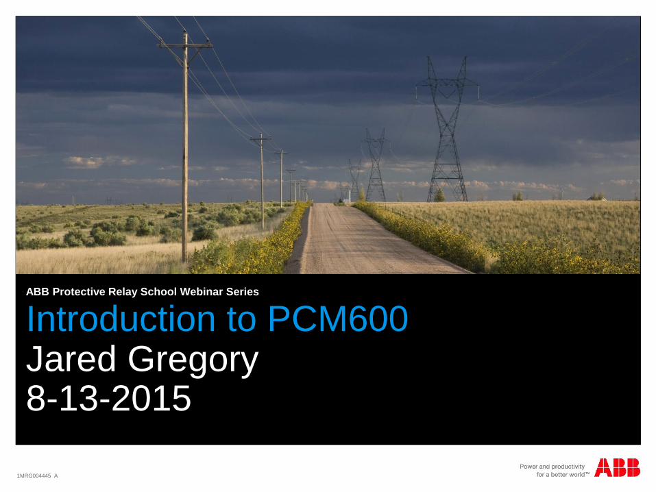
Introduction to PCM600Jared Gregory8-13-2015
ABB Protective Relay School Webinar Series

1MRG004445 A
Section 2
Presenter
Jared is a Customer Support Engineer for the Relion family 670 and 650
product series along with the other items in the Substation Automation
Products Portfolio. He is located in Raleigh, North Carolina. Jared has
been part of the NAM SA Products team since January 2014. Prior to
this he participated in the ABB Power and Automation Leaders Program
from 2011-2013 holding roles as an Application Engineer with the Smart
Grid Center of Excellence, Support and Product Management with
PPMV, and as a Research Engineer with the US Corporate Research
Group. Jared graduated from Missouri University of Science and
Technology with a with B.S. in Electrical Eng and is currently working on
his M.S. in Electrical Eng with a concentration in Power Systems from
the same institution.

1MRG004445 A
Section 2
Learning objectives
This webinar will cover the use of the PCM600 software to configure the Relion
relays.
- Introduction- PCM600- Application Configuration Tool- Parameter Setting Tool- Graphic Display Editor- IEC61850
- Questions

1MRG004445 A
Section 2
PCM600
Configure ABB relays
Interact with ABB IED’s
Build systems
Communications
Project Management
And much more…
“That sounds simple…so I should
be able to just download PCM600
and begin configuring a relay?”
IntroductionOverview

1MRG004445 A
Section 2
PCM600 components
IED connectivity packages
Enables support for specific IED
series in PCM600
Contains “IED modules” for
specific IED types and versions
Communication connectivity
packages
Enables support for different
communication protocols in
PCM600 (communication
between PCM600 and the IED)
These packages can be found
in the Update Manager which is
downloaded whenever PCM600
is installed
IntroductionOverview
1MRG004445 A
Section 2
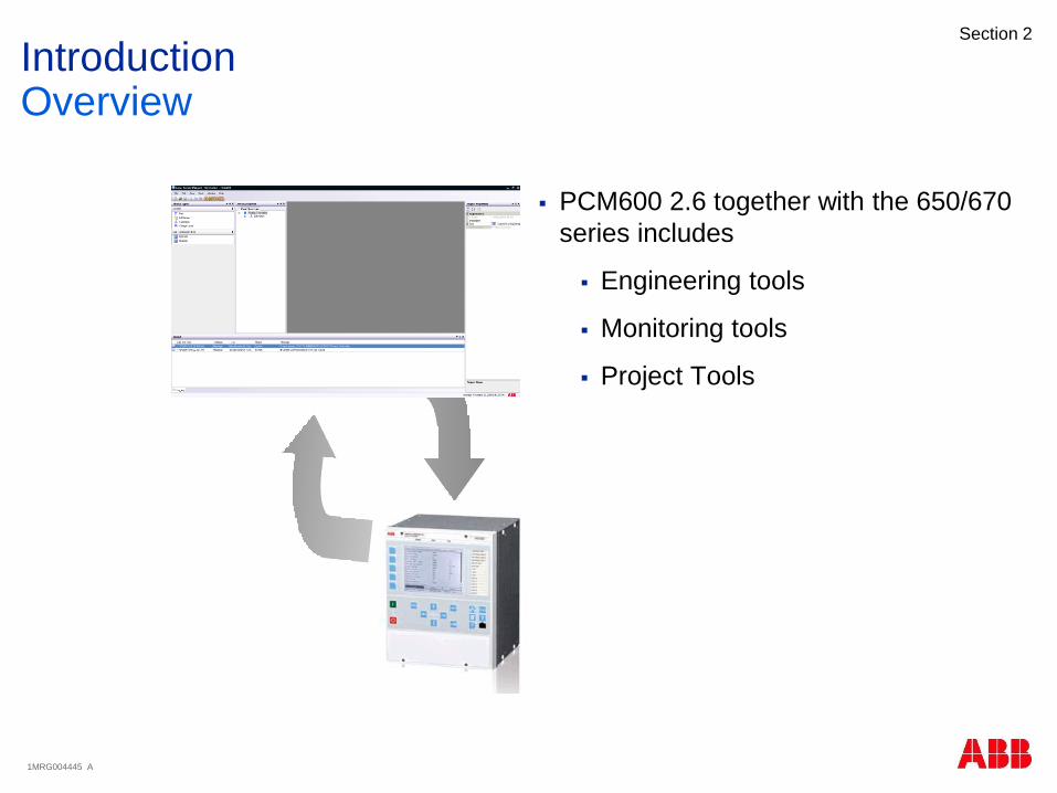
PCM600 2.6 together with the 650/670
series includes
Engineering tools
Monitoring tools
Project Tools
IntroductionOverview

1MRG004445 A
Section 2
Hardware Configuration
Application configuration
Signal matrix
Parameter setting
Graphical display
Communication management
DNP 3.0
IEC61850 Configuration Tool
Communication PCM600/IED
Common Read/Write Tool
Read/Writes all configuration data
with one mouse-click
IntroductionEngineering Tools
Export/Import

1MRG004445 A
Section 2
ACT online monitoring
Event viewer
Signal monitoring
Disturbance handling
IntroductionMonitoring Tools

1MRG004445 A
Section 2
Import/Export
Read/Write to Relay
License Update Tool
IED Compare
IntroductionProject Tools
1MRG004445 A
Section 2
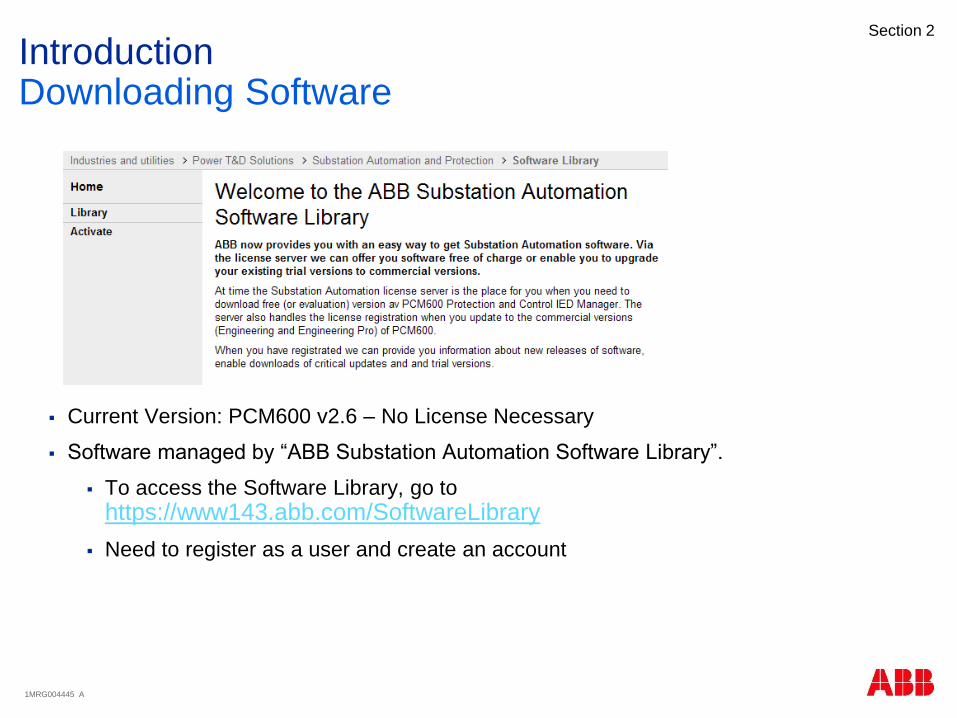
Current Version: PCM600 v2.6 – No License Necessary
Software managed by “ABB Substation Automation Software Library”.
To access the Software Library, go to
https://www143.abb.com/SoftwareLibrary
Need to register as a user and create an account
IntroductionDownloading Software

1MRG004445 A
Section 2
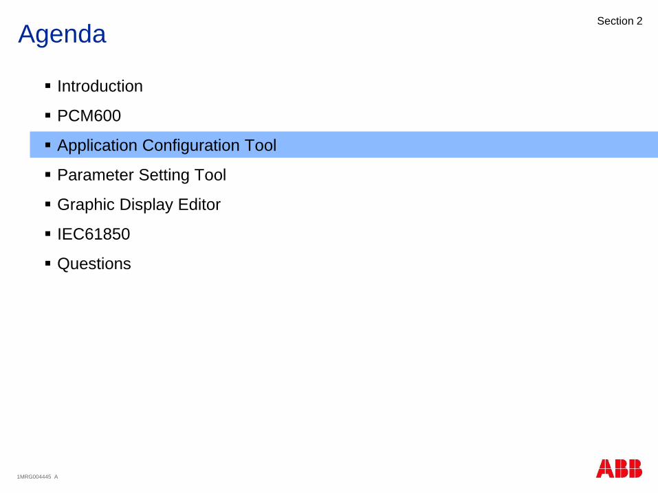
Agenda
Introduction
PCM600
Application Configuration Tool
Parameter Setting Tool
Graphic Display Editor
IEC61850
Questions

1MRG004445 A
Section 2
PCM600Create a New Project
Create New Project
As name suggest, only provides
the option to Create a New
Project.
Entry Fields
Project Name
Description

1MRG004445 A
Section 2
PCM600Open/Manage Project
Open/Manage projects
Create projects
Delete projects
Export projects
All data within the PCM600
project is exported to a file
with extension “.pcmp”.
Used for back-up purposes.
Import projects
Use earlier exported .pcmp
file
Rename projects

1MRG004445 A
Section 2
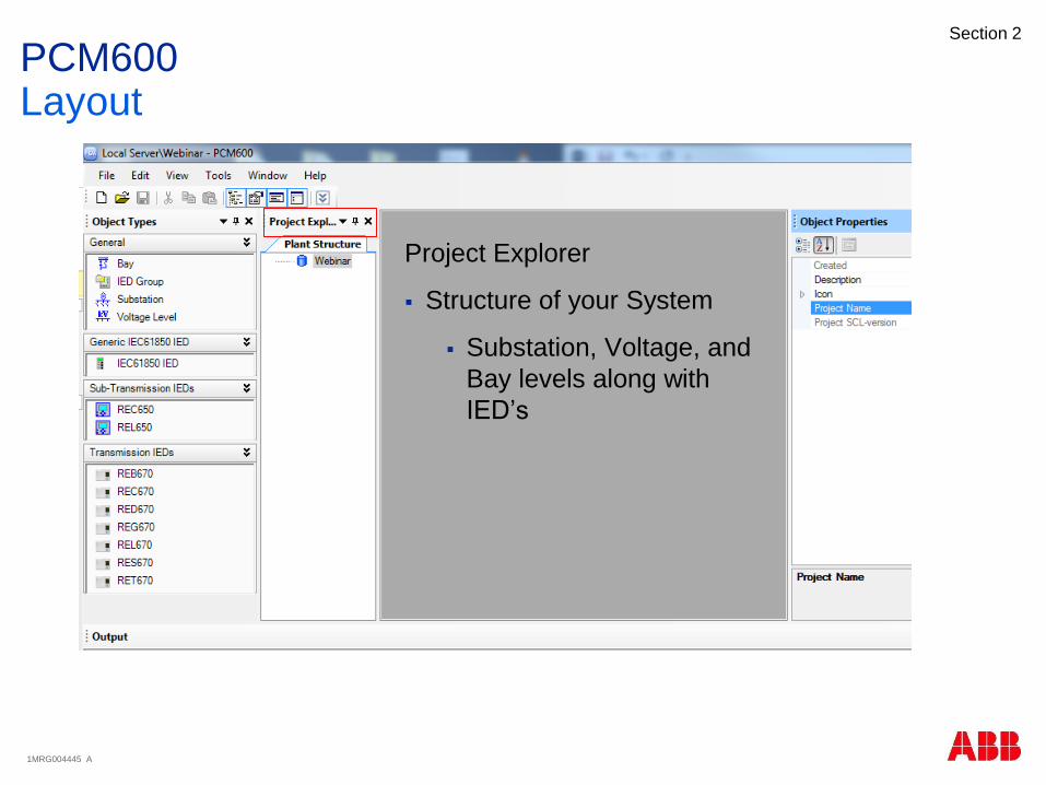
PCM600Layout

1MRG004445 A
Section 2
PCM600Layout
Open/Close –
Project Explorer Window
Object Properties Window
Output Window
Object Types Window
1MRG004445 A
Section 2
PCM600Layout
Project Explorer
Structure of your System
Substation, Voltage, and
Bay levels along with
IED’s
1MRG004445 A
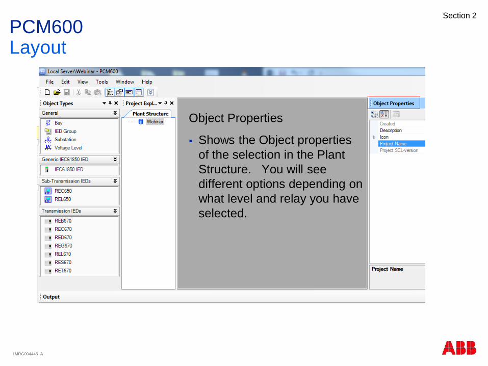
Section 2
PCM600Layout
Object Properties
Shows the Object properties
of the selection in the Plant
Structure. You will see
different options depending on
what level and relay you have
selected.

1MRG004445 A
Section 2
PCM600Layout
Object Types
While in the Plant Structure it provides the
building blocks for building the system.
When you are in the ACT of a relay it provides
you with the function blocks available for building
your logic configuration
1MRG004445 A
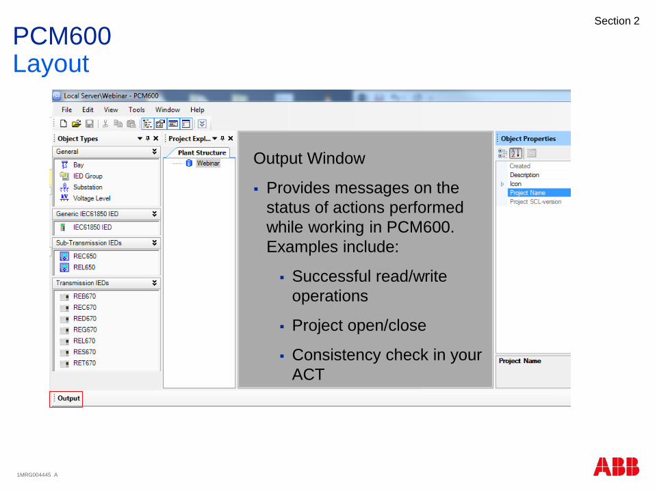
Section 2
PCM600Layout
Output Window
Provides messages on the
status of actions performed
while working in PCM600.
Examples include:
Successful read/write
operations
Project open/close
Consistency check in your
ACT

1MRG004445 A
Section 2
PCM600Layout
Right-click on the different levels to see what
features and tools are available. Each level
provides different options available to the user.
For instance, the Substation Level provides an
Import/Export option for SCD files which does
not exist on other levels. The relay level
provides all the tools for engineering and
monitoring.
1MRG004445 A
Section 2
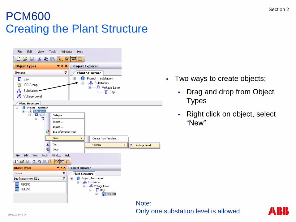
PCM600Creating the Plant Structure
Two ways to create objects;
Drag and drop from Object
Types
Right click on object, select
“New”
Note:
Only one substation level is allowed
1MRG004445 A
Section 2
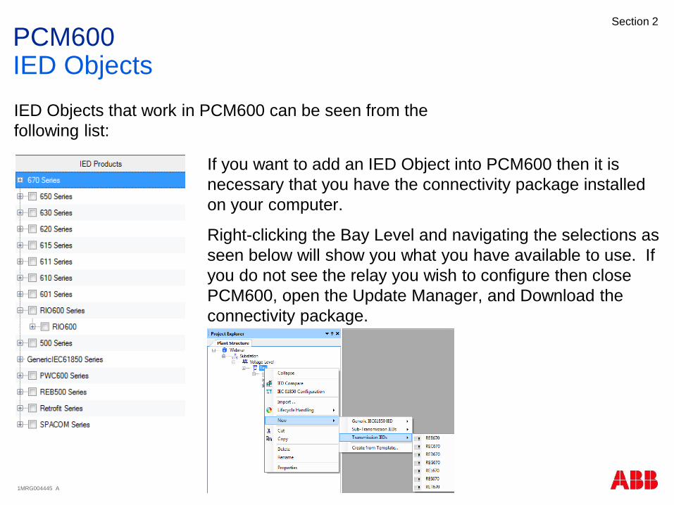
PCM600IED Objects
IED Objects that work in PCM600 can be seen from the
following list:
If you want to add an IED Object into PCM600 then it is
necessary that you have the connectivity package installed
on your computer.
Right-clicking the Bay Level and navigating the selections as
seen below will show you what you have available to use. If
you do not see the relay you wish to configure then close
PCM600, open the Update Manager, and Download the
connectivity package.

1MRG004445 A
Section 2
PCM600IED Objects
Configuration modes
Online configuration
IED available
Offline configuration
No IED available
Use order files
Import
Note: Not possible to
communicate between
PCM600 and IED via SPA
and LON for the 650 series
Select the protocol to use for the PCM600/IED communication

1MRG004445 A
Section 2
PCM600IED Objects – Online Configuration
Set IP address to use
Different default values
for “Front” and “Rear”
port, otherwise no
meaning with the “Port”
selection
IED type, version, display type (Local HMI) and
housing (size of the IED) is automatically
detected in online mode (Use the “Scan” button)

1MRG004445 A
Section 2
PCM600IED Objects – Offline Configuration
IED version must be selected
manually
Order option file available
Enables only ordered SW and
HW in PCM600
No need to synchronize
PCM600 and physical IED
No order option file available
Enables all functionality in
PCM600
Need to synchronize PCM600
and physical IED, use the
License Update Tool
Possible to configure
functionality in PCM600 that
later will not be accepted by the
IED

1MRG004445 A
Section 2
PCM600Hardware Configuration
Possible to manually configure HW/slot positions
This information is already available if you have
created the IED object in “online mode”
Select correct card type in correct slot position

1MRG004445 A
Section 2
PCM600IED Objects – Import
Purpose: To reuse a previously
configured IED object (pcmi file)
Import of pcmi files can be made at the
“Bay” level object in PCM600

1MRG004445 A
Section 2
PCM600License Update Tool
Synchronizes PCM600 IED object with
physical IED capabilities when it comes
to;
Function options
Hardware options
1MRG004445 A
Section 2
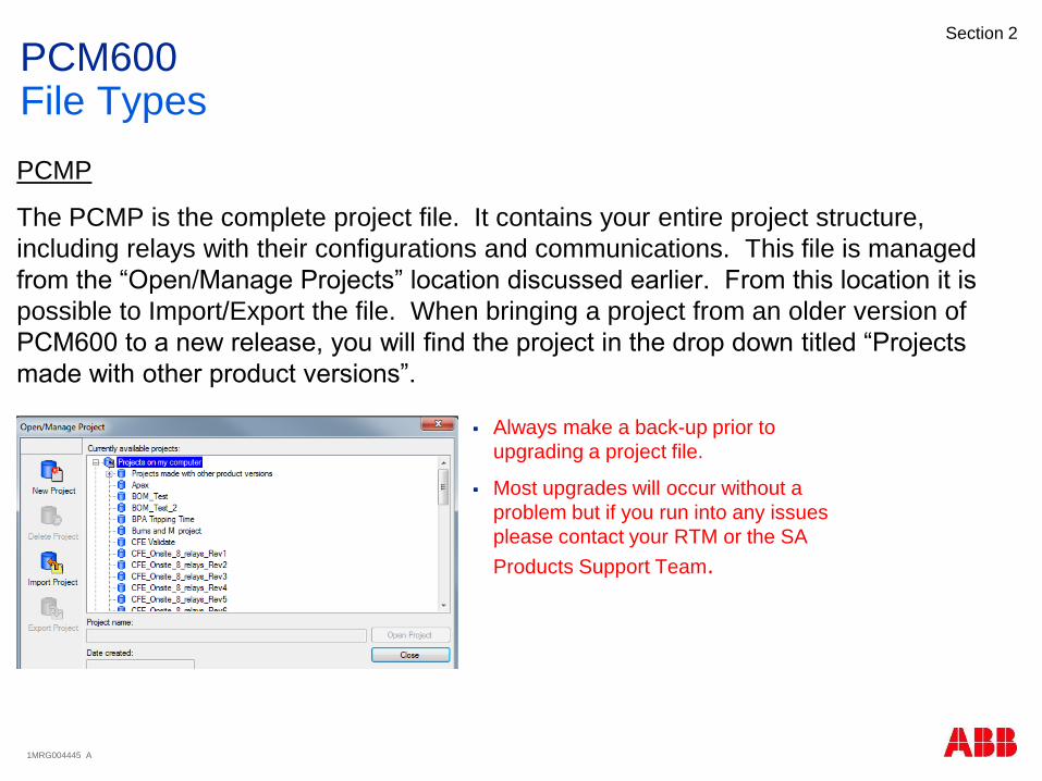
PCM600File Types
PCMP
The PCMP is the complete project file. It contains your entire project structure,
including relays with their configurations and communications. This file is managed
from the “Open/Manage Projects” location discussed earlier. From this location it is
possible to Import/Export the file. When bringing a project from an older version of
PCM600 to a new release, you will find the project in the drop down titled “Projects
made with other product versions”.
Always make a back-up prior to
upgrading a project file.
Most upgrades will occur without a
problem but if you run into any issues
please contact your RTM or the SA
Products Support Team.
1MRG004445 A
Section 2
PCM600File Types
PCMI
The PCMI file represents the entire relay configuration.
IEC61850 Datasets are also included in this file.
If you are using IEC61850 Goose in your project these connections will not be
included when importing/exporting the file
Import or Export pcmi files from the Bay Level
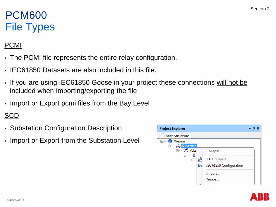
SCD
Substation Configuration Description
Import or Export from the Substation Level
1MRG004445 A
Section 2
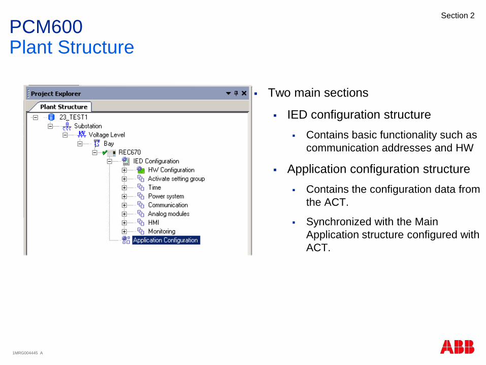
PCM600Plant Structure
Two main sections
IED configuration structure
Contains basic functionality such as
communication addresses and HW
Application configuration structure
Contains the configuration data from
the ACT.
Synchronized with the Main
Application structure configured with
ACT.

1MRG004445 A
Section 2
PCM600Technical Key
Is used for security reasons, more
difficult to communicate with the wrong
IED since the technical key at IED
object in PCM600 and in physical IED
must match.
Unique identifier for each object in the
Plant Structure
Is set automatically by PCM600
Can be modified by the user
To synchronize PCM600 and IED
technical key, use the “Set Technical
Key” Tool
To change the technical key in
PCM600 only, go to object properties
for the IED object

1MRG004445 A
Section 2
PCM600Technical Key
Technical key options
Use IED Technical key
Use PCM600 Technical key
User-defined Technical key
No special characters
Max length 13 characters
No numbers in the beginning
Note that changing the Technical
key might have an impact on the
IEC61850 configuration in your
system
1MRG004445 A
Section 2
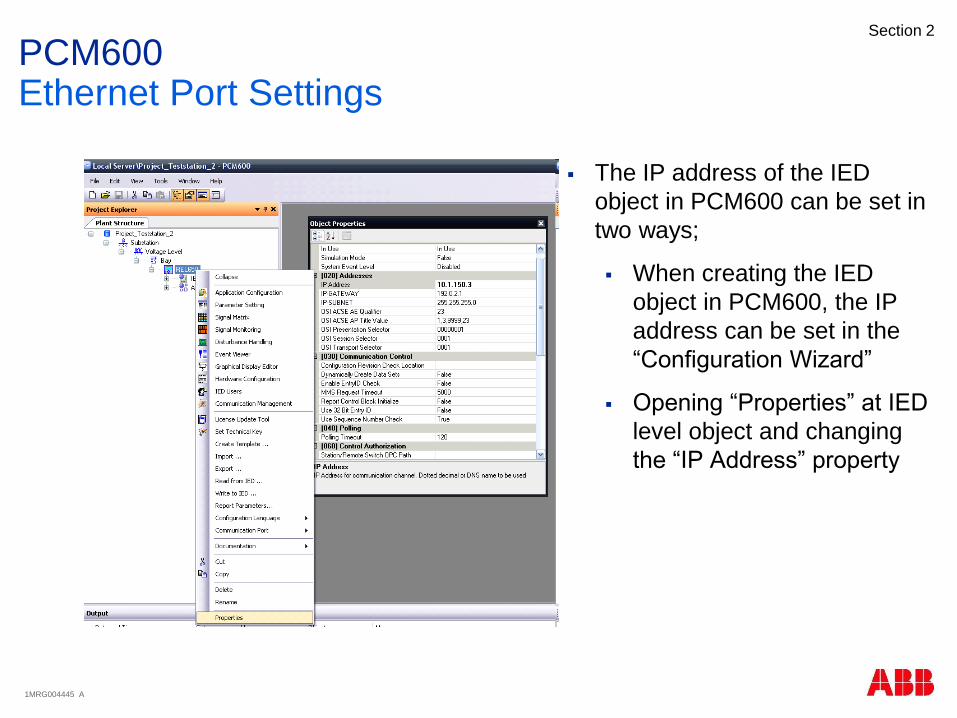
PCM600Ethernet Port Settings
The IP address of the IED
object in PCM600 can be set in
two ways;
When creating the IED
object in PCM600, the IP
address can be set in the
“Configuration Wizard”
Opening “Properties” at IED
level object and changing
the “IP Address” property
1MRG004445 A
Section 2
Agenda
Introduction
PCM600
Application Configuration Tool
Parameter Setting Tool
Graphic Display Editor
IEC61850
Questions

1MRG004445 A
Section 2
The main part of the application engineering is done with
ACT
Graphical programming tool to instantiate function blocks
and make connections between function block
outputs/inputs
With ACT you configure the core functionality of the IED
Application Configuration ToolOverview

1MRG004445 A
Section 2
Contains the possible function block types for the IED type you are working with
Two ways to access and use function blocks:
Function library at Object Types window
Drag & Drop into the ACT workspace
Right mouse click in ACT workspace –> Insert Function Block
Select the function type to instantiate
Application Configuration ToolFunction Library

1MRG004445 A
Section 2
Use Main Applications to create a
logical structure of the configuration
Insert Main Applications
Max 255 Main applications/IED
Delete and copy
Can’t delete default MainApp tab
Contains hidden basic system logic
Copying MainApps
Note that function blocks are not
pasted if there are no free instances
left to use
Rearranging MainApp tabs possible
Like in MS Excel, drag the Main
Application to the correct position
Application Configuration ToolMain Applications
Insert MainApp button
MainApp tabs

1MRG004445 A
Section 2
Renaming is done in Object Properties
Maximum number of characters: 50
No special characters are allowed
Application Configuration ToolRenaming Main Applications

1MRG004445 A
Section 2
The Main Applications are also shown in the Plant Explorer
Synchronized when the configuration in ACT is saved
Application Configuration ToolPlant Explorer
Save button

1MRG004445 A
Section 2
Depending on the size of a
configuration (number of
function blocks used), one or
several pages within one Main
Application might be needed
Each Main Application can have
up to 255 pages
Application Configuration ToolPages

1MRG004445 A
Section 2
Enable grid view
From Toolbar
For easier layout (aligning) of function
blocks
Function blocks snapping to the grid
Grid width is fixed
Application Configuration ToolGrid View
Grid view button

1MRG004445 A
Section 2
Parameterization to do when
inserting function blocks
User defined name (optional)
Not possible for all function
block types
Cycle time (ms)
Execution order and Instance
number
Application Configuration ToolInserting Function Blocks

1MRG004445 A
Section 2
Possibility to show/hide function
block details
Execution order
Cycle time
Instance number
Toggle display
Menu Tools->Options
General setting for all PCM600
projects
Application Configuration ToolFunction Block Details

1MRG004445 A
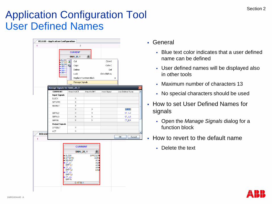
Section 2
General
Blue text color indicates that a user
defined name can be set
User defined names will be shown also
in other tools (like SMT, GDE etc)
Maximum number of characters 13
No special characters should be used
How to set User Defined Names
Select function block and right click
Select Set User Defined Name
How to revert to the default name
Delete the text
Application Configuration ToolUser Defined Names
1MRG004445 A
Section 2
General
Blue text color indicates that a user defined
name can be defined
User defined names will be displayed also
in other tools
Maximum number of characters 13
No special characters should be used
How to set User Defined Names for
signals
Open the Manage Signals dialog for a
function block
How to revert to the default name
Delete the text
Application Configuration ToolUser Defined Names
1MRG004445 A
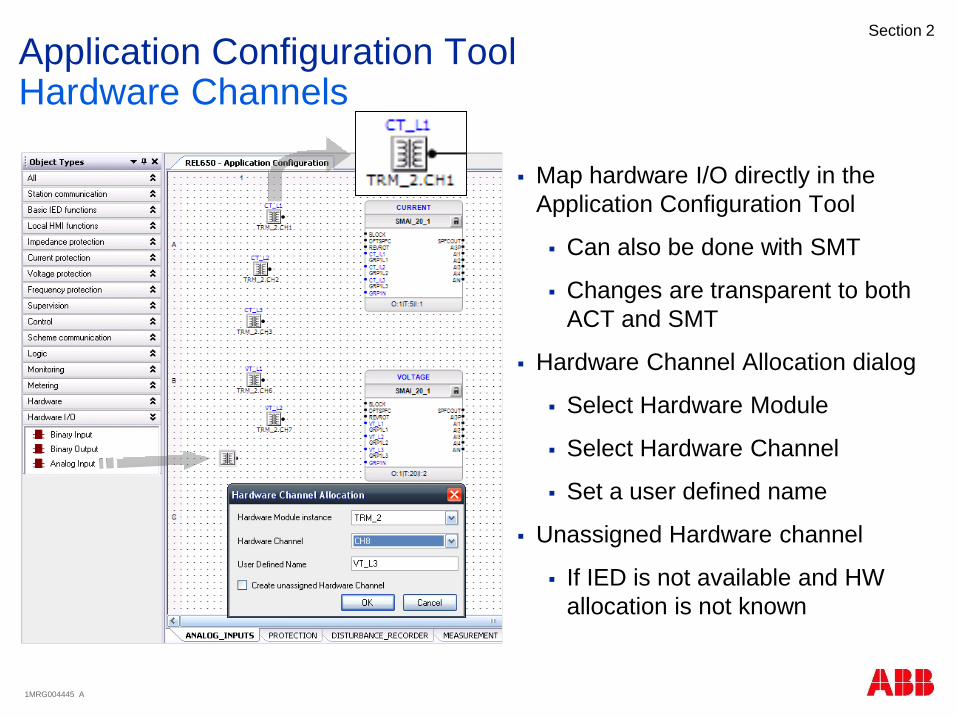
Section 2
Map hardware I/O directly in the
Application Configuration Tool
Can also be done with SMT
Changes are transparent to both
ACT and SMT
Hardware Channel Allocation dialog
Select Hardware Module
Select Hardware Channel
Set a user defined name
Unassigned Hardware channel
If IED is not available and HW
allocation is not known
Application Configuration ToolHardware Channels

1MRG004445 A
Section 2
Purpose of variables: To be able to
make connections between function
blocks residing on different pages or
main applications
Create and connect new variables
Place mouse pointer at the input/output
in question
Right mouse click
Select Connect/Variable/New
Rename variables
At Object Properties
Copy/Paste variables
Output variables are renamed
Input variables keeps the same name
Application Configuration ToolVariables
1MRG004445 A
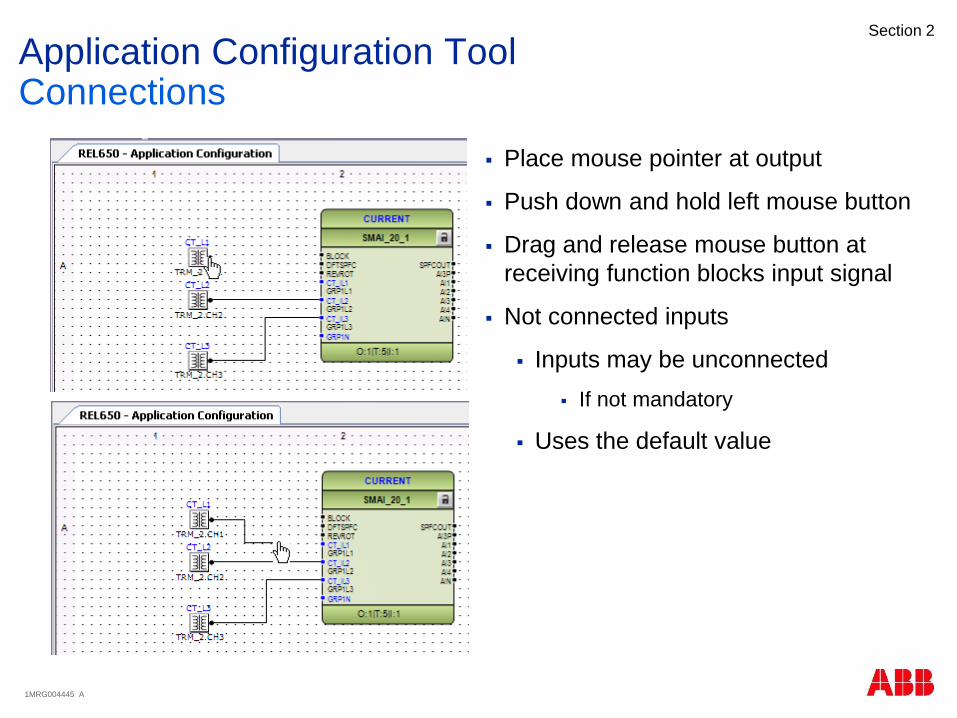
Section 2
Place mouse pointer at output
Push down and hold left mouse button
Drag and release mouse button at
receiving function blocks input signal
Not connected inputs
Inputs may be unconnected
If not mandatory
Uses the default value
Application Configuration ToolConnections

1MRG004445 A
Section 2
Right click at input/output
Select
Connect/Variable/Existing
Select suitable variable in list
Only “legal” variables are
shown -> signal type
sensitive
Application Configuration ToolConnections
1MRG004445 A
Section 2
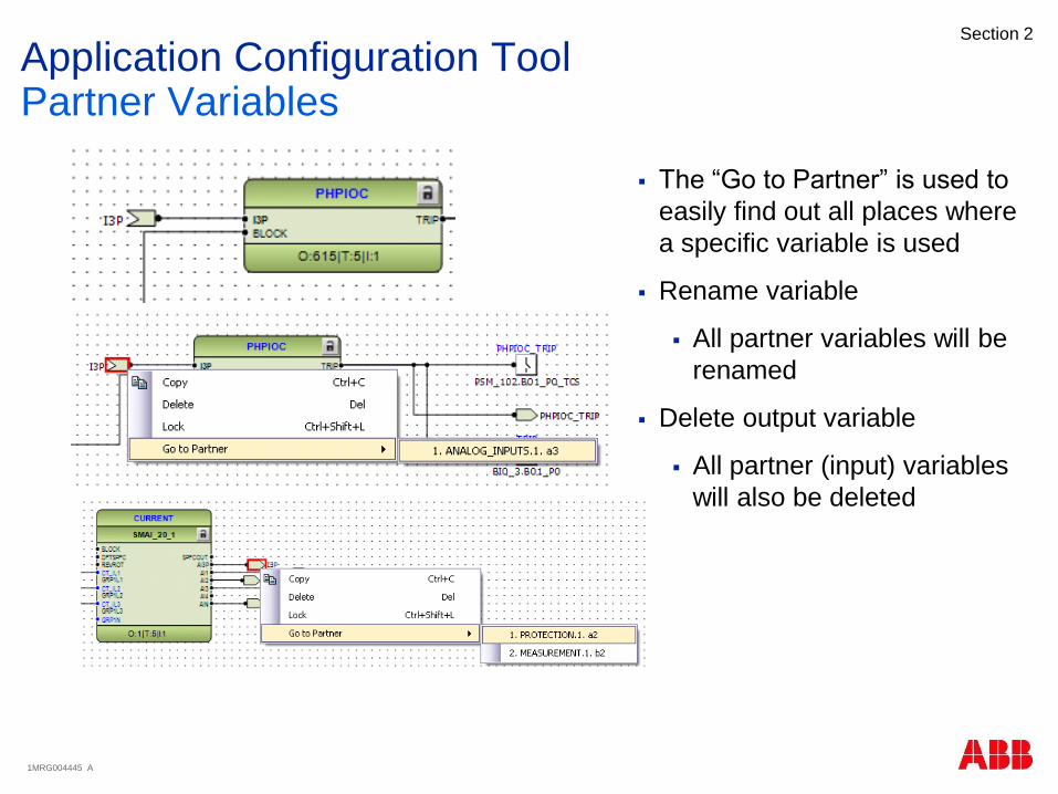
The “Go to Partner” is used to
easily find out all places where
a specific variable is used
Rename variable
All partner variables will be
renamed
Delete output variable
All partner (input) variables
will also be deleted
Application Configuration ToolPartner Variables
1MRG004445 A
Section 2
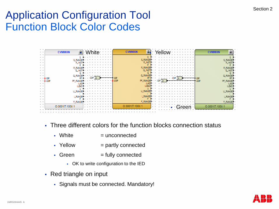
Three different colors for the function blocks connection status
White = unconnected
Yellow = partly connected
Green = fully connected
OK to write configuration to the IED
Red triangle on input
Signals must be connected. Mandatory!
Application Configuration ToolFunction Block Color Codes
White Yellow
Green

1MRG004445 A
Section 2
With Split window active, it is possible to create a connection between function blocks on different pages/main applications as if they were residing on the same page/main application
Only allowed to drag FROM output TO input
Connection represented by variables
Variables are automatically created at output/input signals
Application Configuration ToolSplit Window

1MRG004445 A
Section 2
Connection lines
Automatically placed in the best possible way
Auto routing can not be disabled
But connection lines can manually be moved
Connection lines are rerouted if function blocks are moved
Do not spend time on manual reallocation of connection lines before your configuration is in the final phase
Application Configuration ToolAuto Routing Connections

1MRG004445 A
Section 2
Purpose is to validate the configuration when it comes to
Not connected mandatory signals
Connections between function blocks running in different cycle times
Unconnected variables
Errors and warnings are displayed in the Output window
Errors: Not possible to write configuration to the IED
Warnings: OK to write configuration to the IED but “be aware”
Double click the error/warning in the output window to jump directly to the source in the configuration
Application Configuration ToolValidation

1MRG004445 A
Section 2
Agenda
Introduction
PCM600
Application Configuration Tool
Parameter Setting Tool
Graphic Display Editor
IEC61850
Questions

1MRG004445 A
Section 2
The Signal Matrix Tool is used
for
Mapping internal application
configuration logic (SW IO)
to physical I/O
Binary Inputs
Binary Outputs
Analog Inputs
Communication mapping
IEC61850 GOOSE
Can run in parallel with ACT
Signal MatrixOverview

1MRG004445 A
Section 2
Physical binary inputs
At the top of matrix
Software I/O
At the left of matrix
Function block inputs
To make a mapping
Select square
HW and SW channel are
marked
Double left click for X
Double right click for I
Inverted channel
Press X or I on keyboard
No other keys are accepted
Signal MatrixBinary Inputs
Hardware Modules
Software Modules

1MRG004445 A
Section 2
Physical binary outputs
At the top of the matrix
Software I/O
At the left of the matrix
Function block outputs
Signal MatrixBinary Outputs
1MRG004445 A
Section 2
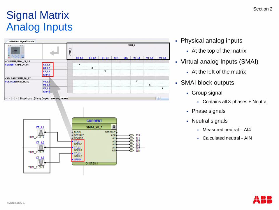
Physical analog inputs
At the top of the matrix
Virtual analog Inputs (SMAI)
At the left of the matrix
SMAI block outputs
Group signal
Contains all 3-phases + Neutral
Phase signals
Neutral signals
Measured neutral – AI4
Calculated neutral - AIN
Signal MatrixAnalog Inputs
1MRG004445 A
Section 2
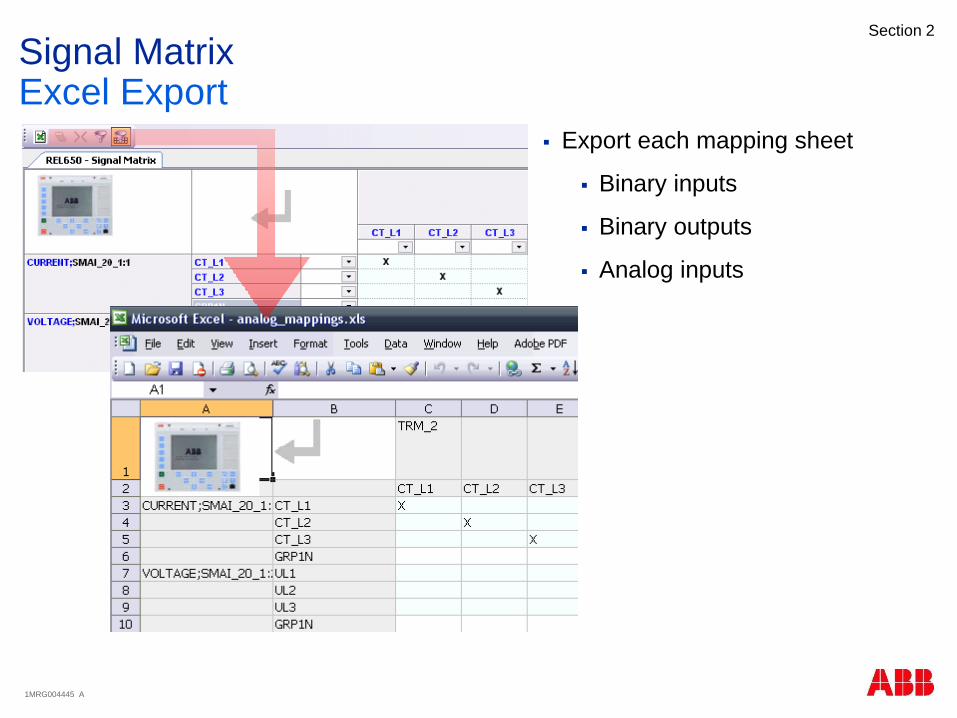
Export each mapping sheet
Binary inputs
Binary outputs
Analog inputs
Signal MatrixExcel Export

1MRG004445 A
Section 2
Agenda
Introduction
PCM600
Application Configuration Tool
Parameter Setting Tool
Graphic Display Editor
IEC61850
Questions

1MRG004445 A
Section 2
PST is started by right clicking the IED object or any object below in the plant
structure. PST shows parameters for selected object (and objects below) in the
plant structure
Parameter Setting ToolOverview
1MRG004445 A
Section 2
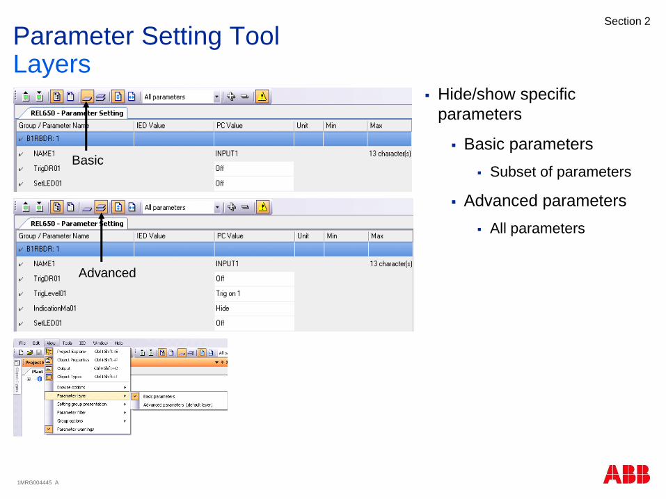
Hide/show specific
parameters
Basic parameters
Subset of parameters
Advanced parameters
All parameters
Parameter Setting ToolLayers
Basic
Advanced
1MRG004445 A
Section 2
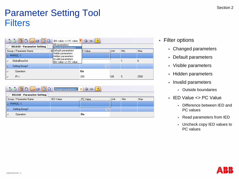
Filter options
Changed parameters
Default parameters
Visible parameters
Hidden parameters
Invalid parameters
Outside boundaries
IED Value <> PC Value
Difference between IED and
PC values
Read parameters from IED
Uncheck copy IED values to
PC values
Parameter Setting ToolFilters
1MRG004445 A
Section 2
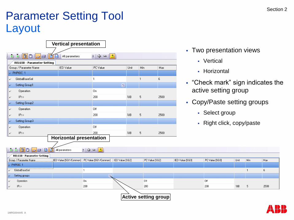
Two presentation views
Vertical
Horizontal
“Check mark” sign indicates the
active setting group
Copy/Paste setting groups
Select group
Right click, copy/paste
Parameter Setting ToolLayout
Vertical presentation
Active setting group
Horizontal presentation
1MRG004445 A
Section 2
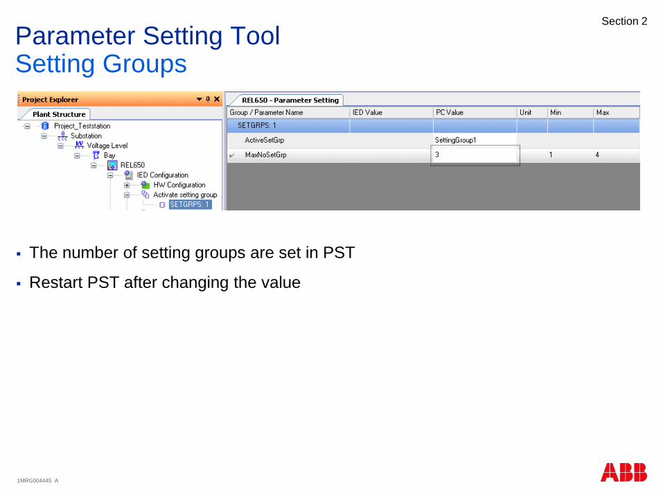
The number of setting groups are set in PST
Restart PST after changing the value
Parameter Setting ToolSetting Groups

1MRG004445 A
Section 2
Read/Write of parameters
Single parameter
A group of parameters
All parameters
Parameter Setting ToolRead/Write
Read from IED Write to IED
1MRG004445 A
Section 2
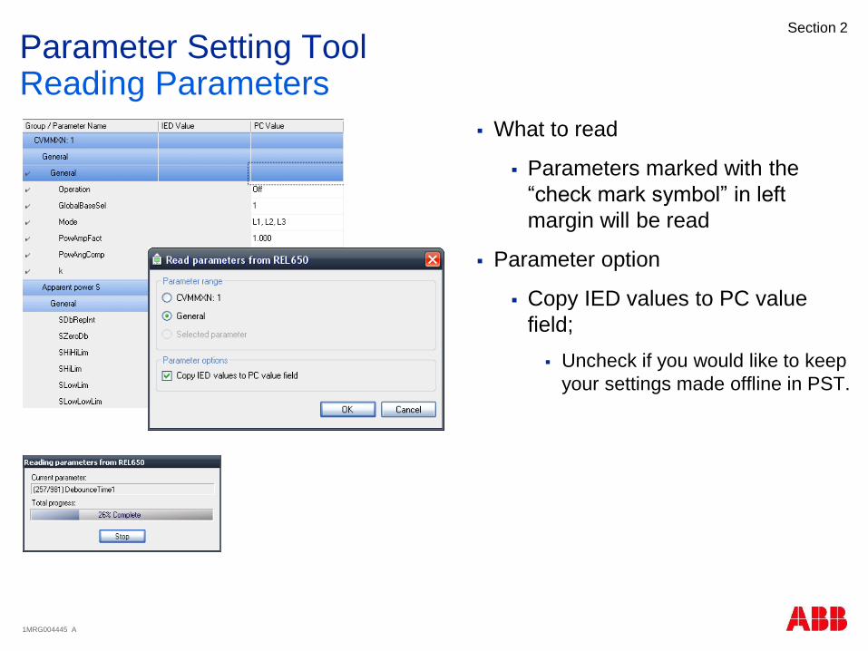
What to read
Parameters marked with the
“check mark symbol” in left
margin will be read
Parameter option
Copy IED values to PC value
field;
Uncheck if you would like to keep
your settings made offline in PST.
Parameter Setting ToolReading Parameters
1MRG004445 A
Section 2
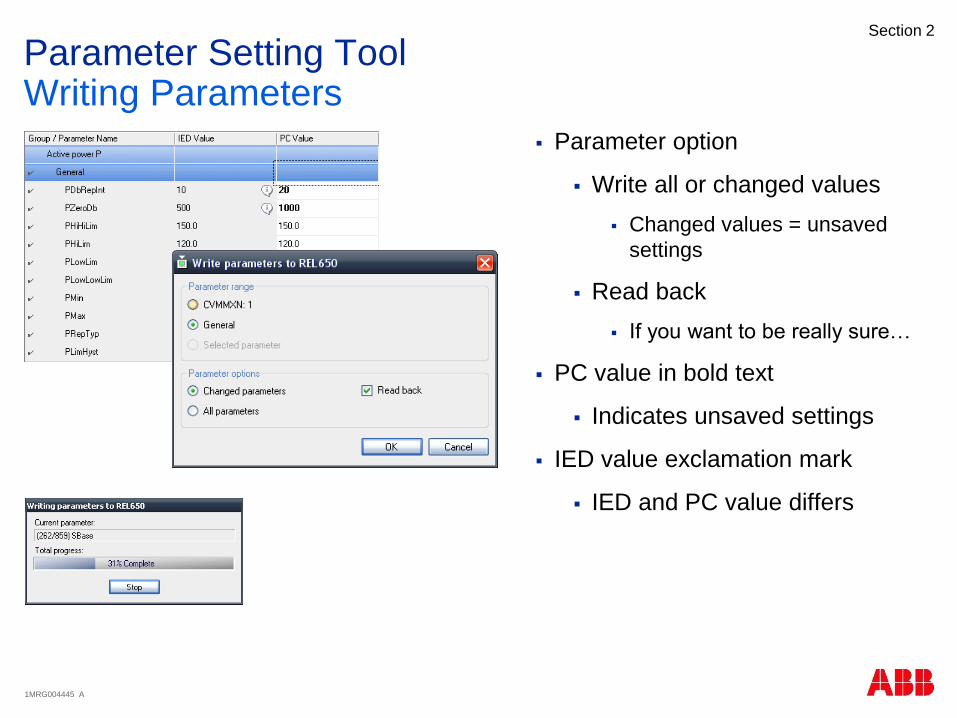
Parameter option
Write all or changed values
Changed values = unsaved
settings
Read back
If you want to be really sure…
PC value in bold text
Indicates unsaved settings
IED value exclamation mark
IED and PC value differs
Parameter Setting ToolWriting Parameters

1MRG004445 A
Section 2
Export/Import to/from XRIO file
Only all parameters possible to
export/import, no subsets.
Parameter Setting ToolImport/Export Parameters

1MRG004445 A
Section 2
Agenda
Introduction
PCM600
Application Configuration Tool
Parameter Setting Tool
Graphic Display Editor
IEC61850
Questions
1MRG004445 A
Section 2
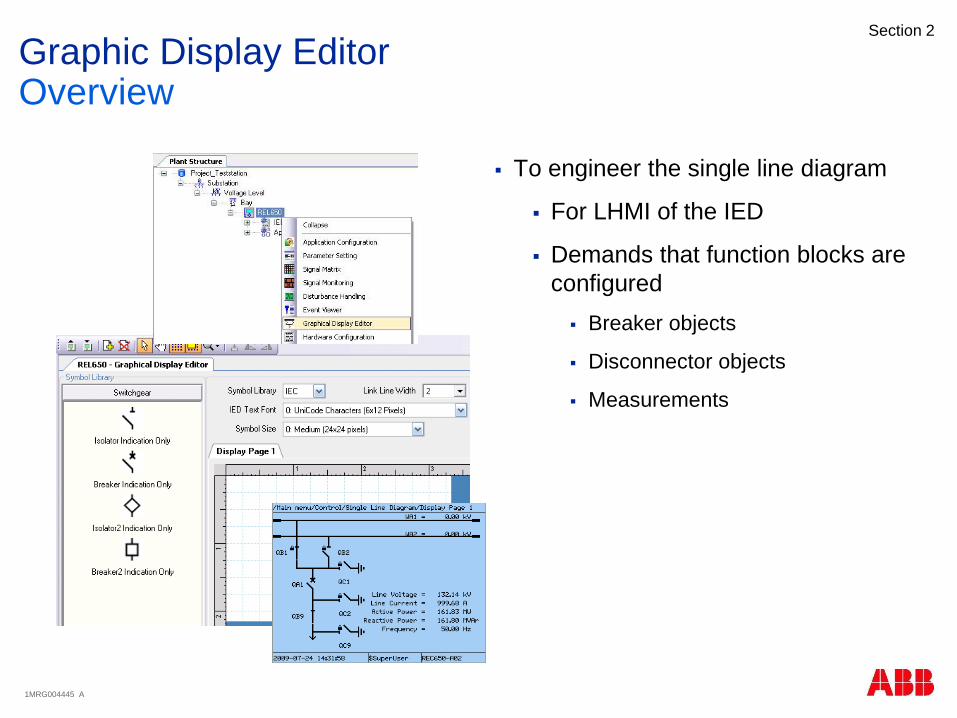
To engineer the single line diagram
For LHMI of the IED
Demands that function blocks are
configured
Breaker objects
Disconnector objects
Measurements
Graphic Display EditorOverview

1MRG004445 A
Section 2
Multiple pages
Add pages
Delete pages
Graphic Display EditorPages

1MRG004445 A
Section 2
Symbol Library
Fixed set of symbols
IEC and ANSI
Custom symbols not possible
Drag and drop
IED Text font
Two font sizes
Symbol size
Only one size
Link line width
Graphic Display EditorInsert Symbol
1MRG004445 A
Section 2
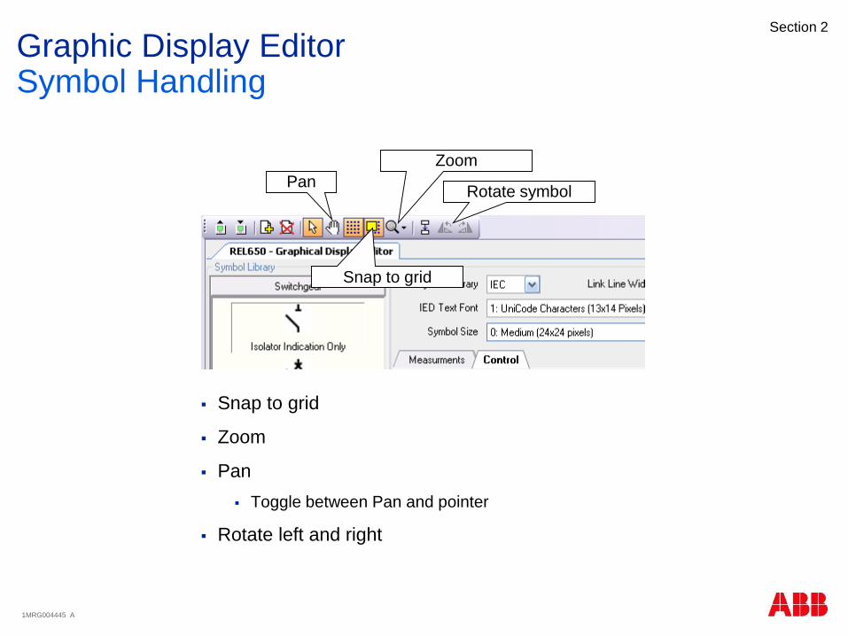
Snap to grid
Zoom
Pan
Toggle between Pan and pointer
Rotate left and right
Graphic Display EditorSymbol Handling
Rotate symbol
Zoom
Snap to grid
Pan

1MRG004445 A
Section 2
Make linking active
Draw link
Place mouse over first
point
Left click once
Draw to second point
Left click once
Graphic Display EditorLink Symbols

1MRG004445 A
Section 2
Associate symbols with functions
Measuring functions
Control functions
User Defined name shown
Make association
Select object
Right click
Select Input Signal
Object Properties
Make association
Renaming
Scaling
Unit Text
Graphic Display EditorAssociate Symbols

1MRG004445 A
Section 2
5 positions
Center
North
East
South
West
Position in Object Properties
Graphic Display EditorSymbol Name Positioning
Symbol name

1MRG004445 A
Section 2
This Read/Writes only the GDE
data
Graphic Display EditorRead/Write
Read button
Write button

1MRG004445 A
Section 2
Agenda
Introduction
PCM600
Application Configuration Tool
Parameter Setting Tool
Graphic Display Editor
IEC61850
Questions

1MRG004445 A
Section 2
IEC61850Overview
PCM600 allows users to edit the IEC61850
information of ABB 650 and 670 devices.
As functions are added into the ACT, they
IEC61850 information for Client/Server will
updated
To edit the IEC61850 information, Right-Click
the relay and select “IEC61850
Configuration”
Once opened the tool will look like the
screenshot from below.
1MRG004445 A
Section 2
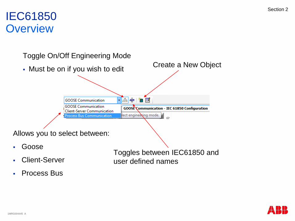
IEC61850Overview
Allows you to select between:
Goose
Client-Server
Process Bus
Toggle On/Off Engineering Mode
Must be on if you wish to edit
Toggles between IEC61850 and
user defined names
Create a New Object
1MRG004445 A
Section 2
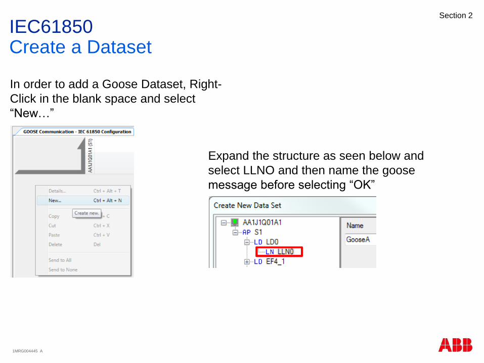
IEC61850Create a Dataset
In order to add a Goose Dataset, Right-
Click in the blank space and select
“New…”
Expand the structure as seen below and
select LLNO and then name the goose
message before selecting “OK”
1MRG004445 A
Section 2
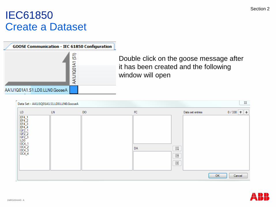
IEC61850Create a Dataset
Double click on the goose message after
it has been created and the following
window will open
1MRG004445 A
Section 2
IEC61850Create a Dataset
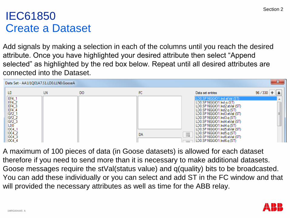
Add signals by making a selection in each of the columns until you reach the desired
attribute. Once you have highlighted your desired attribute then select “Append
selected” as highlighted by the red box below. Repeat until all desired attributes are
connected into the Dataset.
A maximum of 100 pieces of data (in Goose datasets) is allowed for each dataset
therefore if you need to send more than it is necessary to make additional datasets.
Goose messages require the stVal(status value) and q(quality) bits to be broadcasted.
You can add these individually or you can select and add ST in the FC window and that
will provided the necessary attributes as well as time for the ABB relay.

1MRG004445 A
Section 2
IEC61850Create a GOOSE Control Block
In order to add a Goose Control Block, while in the Goose
Communication window select the “Goose Controls” tab found
at the bottom of the page.
Similar to the dataset
creation, right-click the blank
area and select “New”

1MRG004445 A
Section 2
IEC61850Create a GOOSE Control Block
Navigate to LLNO as seen below, create a name for the GCB,
and then select the Data set you would like to be packaged
with the GOOSE Control Block. In this example we have
GooseA connected to GCBA. Once the selections are made
hit “OK”
1MRG004445 A
Section 2
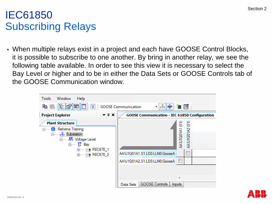
IEC61850Subscribing Relays
When multiple relays exist in a project and each have GOOSE Control Blocks,
it is possible to subscribe to one another. By bring in another relay, we see the
following table available. In order to see this view it is necessary to select the
Bay Level or higher and to be in either the Data Sets or GOOSE Controls tab of
the GOOSE Communication window.

1MRG004445 A
Section 2
IEC61850SCD
SCD file
Substations Configuration
Description
Contents
SCL information for all IED’s within
the substation
Export/Import of SCD file
Done at Substation level
SCL engineering done outside
PCM600, export/import
functionality needed.
Note! When importing SCL files to PCM600, be sure to import an SCL
file that correlates with the PCM600 project or you might loose data
1MRG004445 A
Section 2
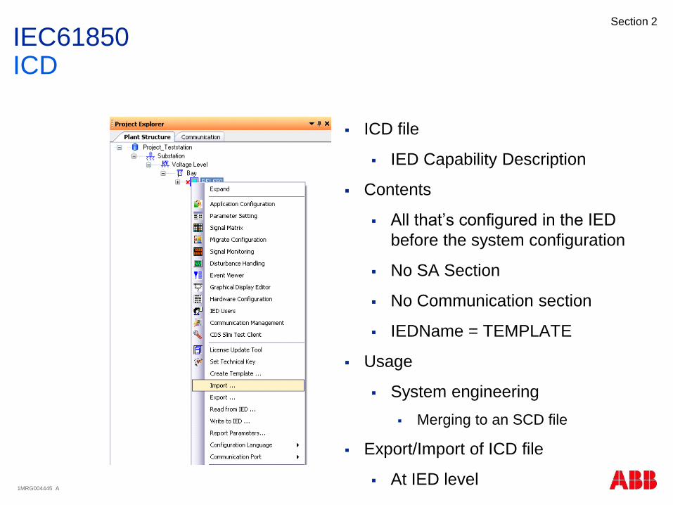
IEC61850ICD
ICD file
IED Capability Description
Contents
All that’s configured in the IED
before the system configuration
No SA Section
No Communication section
IEDName = TEMPLATE
Usage
System engineering
Merging to an SCD file
Export/Import of ICD file
At IED level

1MRG004445 A
Section 2
IEC61850CID
CID file
Configured IED Description
Contents
Extract of the SCD file
SCL information for one specific
IED
Export/Import of ICD file
At IED level
1MRG004445 A
Section 2
Agenda
Introduction
PCM600
Application Configuration Tool
Parameter Setting Tool
Graphic Display Editor
IEC61850
Questions

1MRG004445 A
Section 2
© SA-T TrainingSlide 96
Questions
?????????

1MRG004445 A
Section 2
• Relion Series Relays – Advanced flexible platform for protection and control
• RTU 500 Series – Proven, powerful and open architecture
• MicroSCADA - Advanced control and applications
• Tropos – Secure, robust, high speed wireless solutions
This webinar brought to you by:ABB Power Systems Automation and Communication
We combine innovative, flexible and open products with
engineering and project services to help our customers
address their challenges.

1MRG004445 A
Section 2
Register todayDon’t miss these educational opportunities
Relay school webinar series
Smart grid optimization webinar series
PowerED power education webinar series
Automation & communication solutions for the
evolving power grid
August 31, 2015 in Raleigh, NC
PAC (Protection, Automation & Control) World
September 1-3, 2015 in Raleigh, NC
1MRG004445 A
Section 2
Thank you for your participation
Shortly, you will receive a link to an archive of this presentation.
To view a schedule of remaining webinars in this series, or for more
information on ABB’s protection and control solutions, visit:
www.abb.com/relion

1MRG004445 A
Section 2
© SA-T TrainingSlide 100