section 28 05 11 - requirements for … · web viewd.the contractor shall provide an ess,...
TRANSCRIPT

04-01-18
SECTION 28 05 00COMMON WORK RESULTS FOR ELECTRONIC SAFETY AND SECURITY
SPEC WRITER NOTE: Delete between //____// if not applicable to project. Also delete any other item or paragraph not applicable in the section and renumber the paragraphs. This specification section applies to and shall be included with all work to be performed under the 28000 series of the Master Construction Specifications. The section, though general in nature, should be edited to fit each project.
PART 1 - GENERAL
1.1 DESCRIPTION
SPEC WRITER NOTE: Edit paragraphs A to E based on project requirements.
A. This Section, Common Work Results for Electronic Safety and Security
(ESS), applies to all sections of Division 28.
B. Furnish and install fully functional electronic safety and security
cabling system(s), equipment and approved accessories in accordance with
the specification section(s), drawing(s), and referenced publications.
Capacities and ratings of cable and other items and arrangements for the
specified items are shown on each system’s required Bill of Materials
(BOM) and verified on the approved system drawing(s). If there is a
conflict between contract’s specification(s) and drawings(s), the
contract’s specification requirements shall prevail.
C. The Contractor shall provide a fully functional and operating ESS,
programmed, configured, documented, and tested as required herein and
the respective Safety and Security System Specification(s). The
Contractor shall provide calculations and analysis to support design and
engineering decisions as specified in submittals. The Contractor shall
provide and pay all labor, materials, and equipment, sales and gross
receipts and other taxes. The Contractor shall secure and pay for plan
check fees, permits, other fees, and licenses necessary for the
execution of work as applicable for the project. Give required notices;
the Contractor will comply with codes, ordinances, regulations, and
other legal requirements of public authorities, which bear on the
performance of work.
D. The Contractor shall provide an ESS, installed, programmed, configured,
documented, and tested. The security system shall include but not
28 05 00 - 1

04-01-18
limited to: physical access control, intrusion detection, duress alarms,
elevator control interface, video assessment and surveillance, video
recording and storage, delayed egress, personal protection system,
intercommunication system, fire alarm interface, equipment cabinetry,
dedicated photo badging system and associated live camera, report
printer, photo badge printer, and uninterruptible power supplies (UPS)
interface. Operator training shall not be required as part of the
Security Contractors scope and shall be provided by the Owner. The
Security Contractor shall still be required to provide necessary
maintenance and troubleshooting manuals as well as submittals as
identified herein. The work shall include the procurement and
installation of electrical wire and cables, the installation and testing
of all system components. Inspection, testing, demonstration, and
acceptance of equipment, software, materials, installation,
documentation, and workmanship, shall be as specified herein. The
Contractor shall provide all associated installation support, including
the provision of primary electrical input power circuits.
E. Repair Service Replacement Parts On-site service during the warranty
period shall be provided as specified under “Emergency Service”. The
Contractor shall guarantee all parts and labor for a term of one (1)
year, unless dictated otherwise in this specification from the
acceptance date of the system as described in Part 5 of this
Specification. The Contractor shall be responsible for all equipment,
software, shipping, transportation charges, and expenses associated with
the service of the system for one (1) year. The Contractor shall
provide 24-hour telephone support for the software program at no
additional charge to the owner. Software support shall include all
software updates that occur during the warranty period.
F. Section Includes:
1. Description of Work for Electronic Security Systems,
2. Electronic security equipment coordination with relating Divisions,
3. Submittal Requirements for Electronic Security,
4. Miscellaneous Supporting equipment and materials for Electronic
Security,
5. Electronic security installation requirements.
28 05 00 - 2

04-01-18
1.2 RELATED WORK
SPEC WRITER NOTE: Items listed below apply to all 28 series sections. Delete any item or paragraph not applicable for the project.
A. Section 01 00 00 - GENERAL REQUIREMENTS. For General Requirements.
B. Section 07 84 00 - FIRESTOPPING. Requirements for firestopping
application and use.
C. Section 08 11 73 - SLIDING METAL FIRE DOORS. Requirements for door
installation.
D. Section 08 35 13.13 - ACCORDIAN FOLDING DOORS. Requirements for door
installation.
E. Section 08 34 59 - VAULT DOORS AND DAY GATES. Requirements for door and
gate installation.
F. Section 08 51 13 - ALUMINUM WINDOWS. Requirements for window
installation.
G. Section 08 71 00 - DOOR HARDWARE. Requirements for door installation.
H. Section 10 14 00 - SIGNAGE. Requirements for labeling and signs.
I. Section 14 21 00 - ELECTRIC TRACTION ELEVATORS. Requirements for
elevators.
J. Section 14 24 00 - HYDRAULIC ELEVATORS. Requirements for elevators.
K. Section 26 05 11 - REQUIREMENTS FOR ELECTRICAL INSTALLATIONS.
Requirements for connection of high voltage.
L. Section 26 05 21 - LOW VOLTAGE ELECTRICAL POWER CONDUCTORS AND CABLES
(600 VOLTS AND BELOW). Requirements for power cables.
M. Section 26 05 33 – RACEWAY AND BOXES FOR ELECTRICAL SYSTEMS.
Requirements for infrastructure.
N. Section 26 05 41 - UNDERGROUND ELECTRICAL CONSTRUCTION. Requirements for
underground installation of wiring.
O. Section 26 56 00 - EXTERIOR LIGHTING. Requirements for perimeter
lighting.
P. Section 28 05 13 - CONDUCTORS AND CABLES FOR ELECTRONIC SAFETY AND
SECURITY. Requirements for conductors and cables.
Q. Section 28 05 26 - GROUNDING AND BONDING FOR ELECTRONIC SAFETY AND
SECURITY. Requirements for grounding of equipment.
R. Section 28 05 28.33 - CONDUITS AND BOXES FOR ELECTRONIC SAFETY AND
SECURITY. Requirements for infrastructure.
S. Section 28 08 00 - COMMISIONING OF ELECTRONIC SAFETY AND SECURITY
SYSTEMS. Requirements for Commissioning.
28 05 00 - 3

04-01-18
T. Section 28 13 00 - PHYSICAL ACCESS CONTROL SYSTEMS (PACS). For physical
access control integration.
U. Section 28 13 16 - PHYSICAL ACCESS CONTROL SYSTEM AND DATABASE
MANAGEMENT. Requirements for control and operation of all security
systems.
V. Section 28 13 53 - SECURITY ACCESS DETECTION. Requirements for screening
of personnel and shipments.
W. Section 28 16 00 - INTRUSION DETECTION SYSTEM (IDS). Requirements for
alarm systems.
X. Section 28 23 00 - VIDEO SURVEILLANCE. Requirements for security camera
systems.
Y. Section 28 26 00 - ELECTRONIC PERSONAL PROTECTION SYSTEM (EPPS).
Requirements for emergency and interior communications.
Z. Section 32 31 13 - CHAIN LINK FENCES AND GATES. Requirements for fences.
1.3 DEFINITIONS
SPEC WRITER NOTE: Retain abbreviations that remain after this Section has been edited.
A. AGC: Automatic Gain Control.
B. Basket Cable Tray: A fabricated structure consisting of wire mesh
bottom and side rails.
C. BICSI: Building Industry Consulting Service International.
D. CCD: Charge-coupled device.
E. Central Station: A PC with software designated as the main controlling
PC of the security access system. Where this term is presented with
initial capital letters, this definition applies.
F. Channel Cable Tray: A fabricated structure consisting of a one-piece,
ventilated-bottom or solid-bottom channel section.
G. Controller: An intelligent peripheral control unit that uses a computer
for controlling its operation. Where this term is presented with an
initial capital letter, this definition applies.
H. CPU: Central processing unit.
I. Credential: Data assigned to an entity and used to identify that
entity.
J. DGP: Data Gathering Panel – component of the Physical Access Control
System capable to communicate, store and process information received
from readers, reader modules, input modules, output modules, and
Security Management System.
28 05 00 - 4
04-01-18
K. DTS: Digital Termination Service: A microwave-based, line-of-sight
communications provided directly to the end user.
L. EMI: Electromagnetic interference.
M. EMT: Electric Metallic Tubing.
N. ESS: Electronic Security System.
O. File Server: A PC in a network that stores the programs and data files
shared by users.
P. GFI: Ground fault interrupter.
Q. IDC: Insulation displacement connector.
R. Identifier: A credential card, keypad personal identification number or
code, biometric characteristic, or other unique identification entered
as data into the entry-control database for the purpose of identifying
an individual. Where this term is presented with an initial capital
letter, this definition applies.
S. I/O: Input/Output.
T. Intrusion Zone: A space or area for which an intrusion must be detected
and uniquely identified, the sensor or group of sensors assigned to
perform the detection, and any interface equipment between sensors and
communication link to central-station control unit.
U. Ladder Cable Tray: A fabricated structure consisting of two
longitudinal side rails connected by individual transverse members
(rungs).
V. LAN: Local area network.
W. LCD: Liquid-crystal display.
X. LED: Light-emitting diode.
Y. Location: A Location on the network having a PC-to-Controller
communications link, with additional Controllers at the Location
connected to the PC-to-Controller link with RS-485 communications loop.
Where this term is presented with an initial capital letter, this
definition applies.
Z. Low Voltage: As defined in NFPA 70 for circuits and equipment operating
at less than 50 V or for remote-control and signaling power-limited
circuits.
AA. M-JPEG: Motion – Joint Photographic Experts Group.
BB. MPEG: Moving picture experts group.
CC. NEC: National Electric Code
DD. NEMA: National Electrical Manufacturers Association
EE. NFPA: National Fire Protection Association
28 05 00 - 5

04-01-18
FF. NTSC: National Television System Committee.
GG. NRTL: Nationally Recognized Testing Laboratory.
HH. Open Cabling: Passing telecommunications cabling through open space
(e.g., between the studs of a wall cavity).
II. PACS: Physical Access Control System; A system comprised of cards,
readers, door controllers, servers and software to control the physical
ingress and egress of people within a given space
JJ. PC: Personal computer. This acronym applies to the Central Station,
workstations, and file servers.
KK. PCI Bus: Peripheral component interconnect; a peripheral bus providing
a high-speed data path between the CPU and peripheral devices (such as
monitor, disk drive, or network).
LL. PDF: (Portable Document Format.) The file format used by the Acrobat
document exchange system software from Adobe.
MM. RCDD: Registered Communications Distribution Designer.
NN. RFI: Radio-frequency interference.
OO. RIGID: Rigid conduit is galvanized steel tubing, with a tubing wall
that is thick enough to allow it to be threaded.
PP. RS-232: An TIA/EIA standard for asynchronous serial data communications
between terminal devices. This standard defines a 25-pin connector and
certain signal characteristics for interfacing computer equipment.
QQ. RS-485: An TIA/EIA standard for multipoint communications.
RR. Solid-Bottom or Non-ventilated Cable Tray: A fabricated structure
consisting of integral or separate longitudinal side rails, and a bottom
without ventilation openings.
SS. SMS: Security Management System – A SMS is software that incorporates
multiple security subsystems (e.g., physical access control, intrusion
detection, closed circuit television, intercom) into a single platform
and graphical user interface.
TT. TCP/IP: Transport control protocol/Internet protocol incorporated into
Microsoft Windows.
UU. Trough or Ventilated Cable Tray: A fabricated structure consisting of
integral or separate longitudinal rails and a bottom having openings
sufficient for the passage of air and using 75 percent or less of the
plan area of the surface to support cables.
VV. UPS: Uninterruptible Power Supply
WW. UTP: Unshielded Twisted Pair
28 05 00 - 6

04-01-18
XX. Workstation: A PC with software that is configured for specific limited
security system functions.
1.4 QUALITY ASSURANCE
A. Manufacturers Qualifications: The manufacturer shall regularly and
presently produce, as one of the manufacturer's principal products, the
equipment and material specified for this project, and shall have
manufactured the item for at least three years.
B. Product Qualification:
1. Manufacturer's product shall have been in satisfactory operation, on
three installations of similar size and type as this project, for
approximately three years.
2. The Government reserves the right to require the Contractor to submit
a list of installations where the products have been in operation
before approval.
C. Contractor Qualification:
1. The Contractor or security sub-contractor shall be a licensed
security Contractor with a minimum of five (5) years experience
installing and servicing systems of similar scope and complexity.
The Contractor shall be an authorized regional representative of the
Security Management System’s (PACS) manufacturer. The Contractor
shall provide four (4) current references from clients with systems
of similar scope and complexity which became operational in the past
three (3) years. At least three (3) of the references shall be
utilizing the same system components, in a similar configuration as
the proposed system. The references must include a current point of
contact, company or agency name, address, telephone number, complete
system description, date of completion, and approximate cost of the
project. The owner reserves the option to visit the reference sites,
with the site owner’s permission and representative, to verify the
quality of installation and the references’ level of satisfaction
with the system. The Contractor shall provide copies of system
manufacturer certification for all technicians. The Contractor shall
only utilize factory-trained technicians to install, program, and
service the PACS. The Contractor shall only utilize factory-trained
technicians to install, terminate and service controller/field panels
and reader modules. The technicians shall have a minimum of five (5)
continuous years of technical experience in electronic security
systems. The Contractor shall have a local service facility. The
28 05 00 - 7

04-01-18
facility shall be located within [60] <insert number> miles of the
project site. The local facility shall include sufficient spare
parts inventory to support the service requirements associated with
this contract. The facility shall also include appropriate
diagnostic equipment to perform diagnostic procedures. The Resident
Engineer reserves the option of surveying the company’s facility to
verify the service inventory and presence of a local service
organization.
2. The Contractor shall provide proof project superintendent with BICSI
Certified Commercial Installer Level 1, Level 2, or Technician to
provide oversight of the project.
3. Cable installer must have on staff a Registered Communication
Distribution Designer (RCDD) certified by Building Industry
Consulting Service International. The staff member shall provide
consistent oversight of the project cabling throughout design,
layout, installation, termination and testing.
SPEC WRITER NOTE: In the following paragraph use 4 hours for metropolitan areas and 8 hours for rural areas.
D. Service Qualifications: There shall be a permanent service organization
maintained or trained by the manufacturer which will render satisfactory
service to this installation within // four // eight // hours of receipt
of notification that service is needed. Submit name and address of
service organizations.
1.5 GENERAL ARANGEMENT OF CONTRACT DOCUMENTS
A. The Contract Documents supplement to this specification indicates
approximate locations of equipment. The installation and/or locations
of the equipment and devices shall be governed by the intent of the
design; specification and Contract Documents, with due regard to actual
site conditions, recommendations, ambient factors affecting the
equipment and operations in the vicinity. The Contract Documents are
diagrammatic and do not reveal all offsets, bends, elbows, components,
materials, and other specific elements that may be required for proper
installation. If any departure from the contract documents is deemed
necessary, or in the event of conflicts, the Contractor shall submit
details of such departures or conflicts in writing to the owner or
owner’s representative for his or her comment and/or approval before
initiating work.
28 05 00 - 8

04-01-18
B. Anything called for by one of the Contract Documents and not called for
by the others shall be of like effect as if required or called by all,
except if a provision clearly designed to negate or alter a provision
contained in one or more of the other Contract Documents shall have the
intended effect. In the event of conflicts among the Contract Documents,
the Contract Documents shall take precedence in the following order: the
Form of Agreement; the Supplemental General Conditions; the Special
Conditions; the Specifications with attachments; and the drawings.
1.6 SUBMITTALS
A. Submit in accordance with Section 01 33 23, SHOP DRAWINGS, PRODUCT DATA,
AND SAMPLES.
B. The Government's approval shall be obtained for all equipment and
material before delivery to the job site. Delivery, storage or
installation of equipment or material which has not had prior approval
will not be permitted at the job site.
C. Submittals for individual systems and equipment assemblies which consist
of more than one item or component shall be made for the system or
assembly as a whole. Partial submittals will not be considered for
approval.
1. Mark the submittals, "SUBMITTED UNDER SECTION__________________".
2. Submittals shall be marked to show specification reference including
the section and paragraph numbers.
3. Submit each section separately.
D. The submittals shall include the following:
1. Information that confirms compliance with contract requirements.
Include the manufacturer's name, model or catalog numbers, catalog
information, technical data sheets, shop drawings, pictures,
nameplate data and test reports as required.
SPEC WRITER NOTE: Include the following paragraph for projects in seismic areas of moderate-high, high and very high seismicities as listed in Table 4 of VA Handbook H-18-8, Seismic Design Requirements.
//2. Submittals are required for all equipment anchors and supports.
Submittals shall include weights, dimensions, center of gravity,
standard connections, manufacturer's recommendations and behavior
problems (e.g., vibration, thermal expansion,) associated with
28 05 00 - 9

04-01-18
equipment or piping so that the proposed installation can be properly
reviewed. //
3. Parts list which shall include those replacement parts recommended by
the equipment manufacturer, quantity of parts, current price and
availability of each part.
E. Submittals shall be in full compliance of the Contract Documents. All
submittals shall be provided in accordance with this section.
Submittals lacking the breath or depth these requirements will be
considered incomplete and rejected. Submissions are considered
multidisciplinary and shall require coordination with applicable
divisions to provide a complete and comprehensive submission package.
All submittals shall include adequate descriptive literature, catalog
cuts, shop drawings and other data necessary for the Government to
ascertain that the proposed equipment and materials comply with
specification requirements. Catalog cuts submitted for approval shall
be legible and clearly identify equipment being submitted. Additional
general provisions are as follows:
1. The Contractor shall schedule submittals in order to maintain the
project schedule. For coordination drawings refer to Specification
Section 01 33 10 - Design Submittal Procedures, which outline basic
submittal requirements and coordination. Section 01 33 10 shall be
used in conjunction with this section.
2. The Contractor shall identify variations from requirements of
Contract Documents and state product and system limitations, which
may be detrimental to successful performance of the completed work or
system.
3. Each package shall be submitted at one (1) time for each review and
include components from applicable disciplines (e.g., electrical
work, architectural finishes, door hardware, etc.) which are required
to produce an accurate and detailed depiction of the project.
4. Manufacturer’s information used for submittal shall have pages with
items for approval tagged, items on pages shall be identified, and
capacities and performance parameters for review shall be clearly
marked through use of an arrow or highlighting. Provide space for
Resident Engineer and Contractor review stamps.
5. Technical Data Drawings shall be in the latest version of AutoCAD®,
drawn accurately, and in accordance with VA CAD Standards CAD
Standard Application Guide, and VA BIM Guide. FREEHAND SKETCHES OR
28 05 00 - 10

04-01-18
COPIED VERSIONS OF THE CONSTRUCTION DOCUMENTS WILL NOT BE ACCEPTED.
The Contractor shall not reproduce Contract Documents or copy
standard information as the basis of the Technical Data Drawings. If
departures from the technical data drawings are subsequently deemed
necessary by the Contractor, details of such departures and the
reasons thereof shall be submitted in writing to the Resident
Engineer for approval before the initiation of work.
6. Packaging: The Contractor shall organize the submissions according
to the following packaging requirements.
a. Binders: For each manual, provide heavy duty, commercial quality,
durable three (3) ring vinyl covered loose leaf binders, sized to
receive 8.5 x 11 in paper, and appropriate capacity to accommodate
the contents. Provide a clear plastic sleeve on the spine to hold
labels describing the contents. Provide pockets in the covers to
receive folded sheets.
1) Where two (2) or more binders are necessary to accommodate
data; correlate data in each binder into related groupings
according to the Project Manual table of contents. Cross-
referencing other binders where necessary to provide essential
information for communication of proper operation and/or
maintenance of the component or system.
2) Identify each binder on the front and spine with printed binder
title, Project title or name, and subject matter covered.
Indicate the volume number if applicable.
b. Dividers: Provide heavy paper dividers with celluloid tabs for
each Section. Mark each tab to indicate contents.
c. Protective Plastic Jackets: Provide protective transparent
plastic jackets designed to enclose diagnostic software for
computerized electronic equipment.
d. Text Material: Where written material is required as part of the
manual use the manufacturer's standard printed material, or if not
available, specially prepared data, neatly typewritten on 8.5
inches by 11 inches 20 pound white bond paper.
e. Drawings: Where drawings and/or diagrams are required as part of
the manual, provide reinforced punched binder tabs on the drawings
and bind them with the text.
1) Where oversized drawings are necessary, fold the drawings to
the same size as the text pages and use as a foldout.
28 05 00 - 11

04-01-18
2) If drawings are too large to be used practically as a foldout,
place the drawing, neatly folded, in the front or rear pocket
of the binder. Insert a type written page indicating the
drawing title, description of contents and drawing location at
the appropriate location of the manual.
3) Drawings shall be sized to ensure details and text is of
legible size. Text shall be no less than 1/16” tall.
f. Manual Content: Submit in accordance with Section 01 00 00,
GENERAL REQUIREMENTS.
1) Maintenance and Operation Manuals: Submit as required for
systems and equipment specified in the technical sections.
Furnish four copies, bound in hardback binders, (manufacturer's
standard binders) or an approved equivalent. Furnish one
complete manual as specified in the technical section but in no
case later than prior to performance of systems or equipment
test, and furnish the remaining manuals prior to contract
completion.
2) Inscribe the following identification on the cover: the words
"MAINTENANCE AND OPERATION MANUAL," the name and location of
the system, equipment, building, name of Contractor, and
contract number. Include in the manual the names, addresses,
and telephone numbers of each subcontractor installing the
system or equipment and the local representatives for the
system or equipment.
3) The manuals shall include:
a) Internal and interconnecting wiring and control diagrams
with data to explain detailed operation and control of the
equipment.
b) A control sequence describing start-up, operation, and
shutdown.
c) Description of the function of each principal item of
equipment.
d) Installation and maintenance instructions.
e) Safety precautions.
f) Diagrams and illustrations.
g) Testing methods.
h) Performance data.
28 05 00 - 12

04-01-18
i) Pictorial "exploded" parts list with part numbers. Emphasis
shall be placed on the use of special tools and instruments.
The list shall indicate sources of supply, recommended spare
parts, and name of servicing organization.
j) Appendix; list qualified permanent servicing organizations
for support of the equipment, including addresses and
certified qualifications.
g. Binder Organization: Organize each manual into separate sections
for each piece of related equipment. At a minimum, each manual
shall contain a title page, table of contents, copies of Product
Data supplemented by drawings and written text, and copies of each
warranty, bond, certifications, and service Contract issued. Refer
to Group I through V Technical Data Package Submittal requirements
for required section content.
h. Title Page: Provide a title page as the first sheet of each manual
to include the following information; project name and address,
subject matter covered by the manual, name and address of the
Project, date of the submittal, name, address, and telephone
number of the Contractor, and cross references to related systems
in other operating and/or maintenance manuals.
i. Table of Contents: After the title page, include a type written
table of contents for each volume, arranged systematically
according to the Project Manual format. Provide a list of each
product included, identified by product name or other appropriate
identifying symbols and indexed to the content of the volume.
Where more than one (1) volume is required to hold data for a
particular system, provide a comprehensive table of contents for
all volumes in each volume of the set.
j. General Information Section: Provide a general information section
immediately following the table of contents, listing each product
included in the manual, identified by product name. Under each
product, list the name, address, and telephone number of the
installer and maintenance Contractor. In addition, list a local
source for replacement parts and equipment.
k. Drawings: Provide specially prepared drawings where necessary to
supplement the manufacturers printed data to illustrate the
relationship between components of equipment or systems, or
provide control or flow diagrams. Coordinate these drawings with
28 05 00 - 13

04-01-18
information contained in Project Record Drawings to assure correct
illustration of the completed installation.
l. Manufacturer’s Data: Where manufacturer's standard printed data
is included in the manuals, include only those sheets that are
pertinent to the part or product installed. Mark each sheet to
identify each part or product included in the installation. Where
more than one (1) item in tabular format is included, identify
each item, using appropriate references from the Contract
Documents. Identify data that is applicable to the installation
and delete references to information which is not applicable.
m. Where manufacturer's standard printed data is not available and
the information is necessary for proper operation and maintenance
of equipment or systems, or it is necessary to provide additional
information to supplement the data included in the manual, prepare
written text to provide the necessary information. Organize the
text in a consistent format under a separate heading for different
procedures. Where necessary, provide a logical sequence of
instruction for each operating or maintenance procedure. Where
similar or more than one product is listed on the submittal the
Contractor shall differentiate by highlighting the specific
product to be utilized.
n. Calculations: Provide a section for circuit and panel
calculations.
o. Loading Sheets: Provide a section for DGP Loading Sheets.
p. Certifications: Provide section for Contractor’s manufacturer
certifications.
7. Contractor Review: Review submittals prior to transmittal.
Determine and verify field measurements and field construction
criteria. Verify manufacturer’s catalog numbers and conformance of
submittal with requirements of contract documents. Return non-
conforming or incomplete submittals with requirements of the work and
contract documents. Apply Contractor’s stamp with signature
certifying the review and verification of products occurred, and the
field dimensions, adjacent construction, and coordination of
information is in accordance with the requirements of the contract
documents.
8. Resubmission: Revise and resubmit submittals as required within 15
calendar days of return of submittal. Make resubmissions under
28 05 00 - 14

04-01-18
procedures specified for initial submittals. Identify all changes
made since previous submittal.
9. Product Data: Within 15 calendar days after execution of the
contract, the Contractor shall submit for approval a complete list of
all of major products proposed for use. The data shall include name
of manufacturer, trade name, model number, the associated contract
document section number, paragraph number, and the referenced
standards for each listed product.
F. Group 1 Technical Data Package: Group I Technical Data Package shall be
one submittal consisting of the following content and organization.
Refer to VA Special Conditions Document for drawing format and content
requirements. The data package shall include the following:
1. Section I - Drawings:
a. General – Drawings shall conform to VA CAD Standards Guide. All
text associated with security details shall be 1/8” tall and meet
VA text standard for AutoCAD™ drawings.
b. Cover Sheet – Cover sheet shall consist of Project Title and
Address, Project Number, Area and Vicinity Maps.
c. General Information Sheets – General Information Sheets shall
consist of General Notes, Abbreviations, Symbols, Wire and Cable
Schedule, Project Phasing, and Sheet Index.
d. Floor Plans – Floor plans shall be produced from the Architectural
backgrounds issued in the Construction Documents. The contractor
shall receive floor plans from the prime A/E to develop these
drawing sets. Security devices shall be placed on drawings in
scale. All text associated with security details shall be 1/8”
tall and meet VA text standard for AutoCAD™ drawings. Floor plans
shall identify the following:
1) Security devices by symbol,
2) The associated device point number (derived from the loading
sheets),
3) Wire & cable types and counts
4) Conduit sizing and routing
5) Conduit riser systems
6) Device and area detail call outs
e. Architectural details – Architectural details shall be produced
for each device mounting type (door details for EECS and IDS,
28 05 00 - 15

04-01-18
Intrusion Detection system (motion sensor, vibration, microwave
Motion Sensor and Camera mounting,
f. Riser Diagrams – Contractor shall provide a riser diagram
indicating riser architecture and distribution of the SMS
throughout the facility (or area in scope).
g. Block Diagrams – Contractor shall provide a block diagram for the
entire system architecture and interconnections with SMS
subsystems. Block diagram shall identify SMS subsystem (e.g.,
electronic entry control, intrusion detection, closed circuit
television, intercom, and other associated subsystems)
integration; and data transmission and media conversion
methodologies.
h. Interconnection Diagrams – Contractor shall provide
interconnection diagram for each sensor, and device component.
Interconnection diagram shall identify termination locations,
standard wire detail to include termination schedule. Diagram
shall also identify interfaces to other systems such as elevator
control, fire alarm systems, and security management systems.
i. Security Details:
1) Panel Assembly Detail – For each panel assembly, a panel
assembly details shall be provided identifying individual panel
component size and content.
2) Panel Details – Provide security panel details identify general
arrangement of the security system components, backboard size,
wire through size and location, and power circuit requirements.
3) Device Mounting Details – Provide mounting detailed drawing for
each security device (physical access control system, intrusion
detection, video surveillance and assessment, and intercom
systems) for each type of wall and ceiling configuration in
project. Device details shall include device, mounting detail,
wiring and conduit routing.
4) Details of connections to power supplies and grounding
5) Details of surge protection device installation
6) Sensor detection patterns – Each system sensor shall have
associated detection patterns.
7) Equipment Rack Detail – For each equipment rack, provide a
scaled detail of the equipment rack location and rack space
utilization. Use of BISCI wire management standards shall be
28 05 00 - 16

04-01-18
employed to identify wire management methodology. Transitions
between equipment racks shall be shown to include use vertical
and horizontal latter rack system.
8) Security Control Room – The contractor shall provide a layout
plan for the Security Control Room. The layout plan shall
identify all equipment and details associated with the
installation.
9) Operator Console – The contractor shall provide a layout plan
for the Operator Console. The layout plan shall identify all
equipment and details associated with the installation.
Equipment room - the contractor shall provide a layout plan for
the equipment room. The layout plan shall identify all
equipment and details associated with the installation.
10) Equipment Room – Equipment room details shall provide
architectural, electrical, mechanical, plumbing, IT/Data and
associated equipment and device placements both vertical and
horizontally.
j. Electrical Panel Schedule – Electrical Panel Details shall be
provided for all SMS systems electrical power circuits. Panel
details shall be provided identifying panel type (Standard,
Emergency Power, Emergency/Uninterrupted Power Source, and
Uninterrupted Power Source Only), panel location, circuit number,
and circuit amperage rating.
k. Door Schedule – A door schedule shall be developed for each door
equipped with electronic security components. At a minimum, the
door schedule shall be coordinated with Division 08 work and
include the following information:
1) Item Number
2) Door Number (Derived from A/E Drawings)
3) Floor Plan Sheet Number
4) Standard Detail Number
5) Door Description (Derived from Loading Sheets)
6) Data Gathering Panel Input Number
7) Door Position or Monitoring Device Type & Model Number
8) Lock Type, Model Number & Power Input/Draw (standby/active)
9) Card Reader Type & Model Number
10) Shunting Device Type & Model Number
11) Sounder Type & Model Number
28 05 00 - 17

04-01-18
12) Manufacturer
13) Misc. devices as required
a) Delayed Egress Type & Model Number
b) Intercom
c) Camera
d) Electric Transfer Hinge
e) Electric Pass-through device
14) Remarks column indicating special notes or door configurations
2. Camera Schedule - A camera schedule shall be developed for each
camera. Contractors shall coordinate with the Resident Engineer to
determine camera starting numbers and naming conventions. All
drawings shall identify wire and cable standardization methodology.
Color coding of all wiring conductors and jackets is required and
shall be communicated consistently throughout the drawings package
submittal. At a minimum, the camera schedule shall include the
following information:
a. Item Number
b. Camera Number
c. Naming Conventions
d. Description of Camera Coverage
e. Camera Location
f. Floor Plan Sheet Number
g. Camera Type
h. Mounting Type
i. Standard Detail Reference
j. Power Input & Draw
k. Power Panel Location
l. Remarks Column for Camera
3. Section II – Data Gathering Panel Documentation Package
a. Contractor shall provide Data Gathering Panel (DGP) input and
output documentation packages for review at the Shop Drawing
submittal stage and also with the as-built documentation package.
The documentation packages shall be provided in both printed and
magnetic form at both review stages.
b. The Contractor shall provide loading sheet documentation package
for the associated DGP, including input and output boards for all
field panels associated with the project. Documentation shall be
provided in current version Microsoft Excel spreadsheets following
28 05 00 - 18

04-01-18
the format currently utilized by VA. A separate spreadsheet file
shall be generated for each DGP and associated field panels.
c. The spreadsheet names shall follow a sequence that shall display
the spreadsheets in numerical order according to the DGP system
number. The spreadsheet shall include the prefix in the file name
that uniquely identifies the project site. The spreadsheet shall
detail all connected items such as card readers, alarm inputs, and
relay output connections. The spreadsheet shall include an
individual section (row) for each panel input, output and card
reader. The spreadsheet shall automatically calculate the system
numbers for card readers, inputs, and outputs based upon data
entered in initialization fields.
d. All entries must be verified against the field devices. Copies of
the floor plans shall be forwarded under separate cover.
e. The DGP spreadsheet shall include an entry section for the
following information:
1) DGP number
2) First Reader Number
3) First Monitor Point Number
4) First Relay Number
5) DGP, input or output Location
6) DGP Chain Number
7) DGP Cabinet Tamper Input Number
8) DGP Power Fail Input Number
9) Number of Monitor Points Reserved For Expansion Boards
10) Number of Control Points (Relays) Reserved For Expansion Boards
f. The DGP, input module and output module spreadsheets shall
automatically calculate the following information based upon the
associated entries in the above fields:
1) System Numbers for Card Readers
2) System Numbers for Monitor Point Inputs
3) System Numbers for Control Points (Relays)
4) Next DGP or input module First Monitor Point Number
5) Next DGP or output module First Control Point Number
g. The DGP spreadsheet shall provide the following information for
each card reader:
1) DGP Reader Number
2) System Reader Number
28 05 00 - 19

04-01-18
3) Cable ID Number
4) Description Field (Room Number)
5) Description Field (Device Type i.e.: In Reader, Out Reader,
etc.)
6) Description Field
7) DGP Input Location
8) Date Test
9) Date Passed
10) Cable Type
11) Camera Numbers (of cameras viewing the reader location)
h. The DGP and input module spreadsheet shall provide the following
information for each monitor point (alarm input).
1) DGP Monitor Point Input Number
2) System Monitor Point Number
3) Cable ID Number
4) Description Field (Room Number)
5) Description Field (Device Type i.e.: Door Contact, Motion
Detector, etc.)
7) DGP or input module Input Location
8) Date Test
9) Date Passed
10) Cable Type
11) Camera Numbers (of associated alarm event preset call-ups)
i. The DGP and output module spreadsheet shall provide the following
information for each control point (output relay).
1) DGP Control Point (Relay) Number
2) System (Control Point) Number
3) Cable ID Number
4) Description Field (Room Number)
5) Description Field (Device: Lock Control, Local Sounder, etc.)
6) Description Field
7) DGP or OUTPUT MODULE Output Location
8) Date Test
9) Date Passed Cable Type
10) Camera Number (of associated alarm event preset call-ups)
j. The DGP, input module and output module spreadsheet shall include
the following information or directions in the header and footer:
1) Header
28 05 00 - 20

04-01-18
a) DGP Input and Output Worksheet
b) Enter Beginning Reader, Input, and Output Starting Numbers
and Sheet Will Automatically Calculate the Remaining System
Numbers.
2) Footer
a) File Name
b) Date Printed
c) Page Number
SPEC WRITER NOTE: Delete following paragraph describing mock-up construction if not required by the project.
4. Section III - Construction Mock-up: In areas with exposed
EMT/Conduit Raceways, contractor shall conceal raceway as much as
practical and unobtrusively. In addition, historic significance must
be considered to determine installation means and methods for
approval by the owner.
5. Section IV - Manufacturers’ Data: The data package shall include
manufacturers’ data for all materials and equipment, including
sensors, local processors and console equipment provided under this
specification.
6. Section V - System Description and Analysis: The data package shall
include system descriptions, analysis, and calculations used in
sizing equipment required by these specifications. Descriptions and
calculations shall show how the equipment will operate as a system to
meet the performance requirements of this specification. The data
package shall include the following:
a. Central processor memory size; communication speed and protocol
description; rigid disk system size and configuration; flexible
disk system size and configuration; back-up media size and
configuration; alarm response time calculations; command response
time calculations; start-up operations; expansion capability and
method of implementation; sample copy of each report specified;
and color photographs representative of typical graphics.
b. Software Data: The data package shall consist of descriptions of
the operation and capability of the system, and application
software as specified.
c. Overall System Reliability Calculations: The data package shall
include all manufacturers’ reliability data and calculations
required to show compliance with the specified reliability.
28 05 00 - 21

04-01-18
7. Section VI – Certifications & References: All specified
manufacturer’s certifications shall be included with the data
package. Contractor shall provide Project references as outlined in
Paragraph 1.4 “Quality Assurance”.
G. Group II Technical Data Package
1. The Contractor shall prepare a report of “Current Site Conditions”
and submit a report to the Resident Engineer documenting changes to
the site, particularly those conditions that affect performance of
the system to be installed. The Contractor shall provide
specification sheets, or written functional requirements to support
the findings, and a cost estimate to correct those site changes or
conditions which affect the installation of the system or its
performance. The Contractor shall not correct any deficiency without
written permission from the COTR.
2. System Configuration and Functionality: The contractor shall provide
the results of the meeting with VA to develop system requirements and
functionality including but not limited to:
a. Baseline configuration
b. Access levels
c. Schedules (intrusion detection, physical access control, holidays,
etc.)
d. Badge database
e. System monitoring and reporting (unit level and central control)
f. Naming conventions and descriptors
H. Group III Technical Data Package
1. Development of Test Procedures: The Contractor will prepare
performance test procedures for the system testing. The test
procedures shall follow the format of the VA Testing procedures and
be customized to the contract requirements. The Contractor will
deliver the test procedures to the Resident Engineer for approval at
least 60 calendar days prior to the requested test date.
I. Group IV Technical Data Package
1. Performance Verification Test
a. Based on the successful completion of the pre-delivery test, the
Contractor shall finalize the test procedures and report forms for
the performance verification test (PVT) and the endurance test.
The PVT shall follow the format, layout and content of the pre-
delivery test. The Contractor shall deliver the PVT and endurance
28 05 00 - 22

04-01-18
test procedures to the Resident Engineer for approval. The
Contractor may schedule the PVT after receiving written approval
of the test procedures. The Contractor shall deliver the final
PVT and endurance test reports within 14 calendar days from
completion of the tests. Refer to Part 3 of this section for
System Testing and Acceptance requirements.
2. Training Documentation
a. New Facilities and Major Renovations: Familiarization training
shall be provided for new equipment or systems. Training can
include site familiarization training for VA technicians and
administrative personnel. Training shall include general
information on new system layout including closet locations,
turnover of the completed system including all documentation,
including manuals, software, key systems, and full system
administration rights. Lesson plans and training manuals training
shall be oriented to type of training to be provided.
b. New Unit Control Room:
1) Provide the security personnel with training in the use,
operation, and maintenance of the entire control room system
(Unit Control and Equipment Rooms). The training documentation
must include the operation and maintenance. The first of the
training sessions shall take place prior to system turnover and
the second immediately after turnover. Coordinate the training
sessions with the Owner. Completed classroom sessions will be
witnessed and documented by the Architect/Engineer, and
approved by the Resident Engineer. Instruction is not to begin
until the system is operational as designed.
2) The training documents will cover the operation and the
maintenance manuals and the control console operators’ manuals
and service manuals in detail, stressing all important
operational and service diagnostic information necessary for
the maintenance and operations personnel to efficiently use and
maintain all systems.
3) Provide an illustrated control console operator's manual and
service manual. The operator's manual shall be written in
laymen's language and printed so as to become a permanent
reference document for the operators, describing all control
panel switch operations, graphic symbol definitions and all
28 05 00 - 23

04-01-18
indicating functions and a complete explanation of all
software.
4) The service manual shall be written in laymen's language and
printed so as to become a permanent reference document for
maintenance personnel, describing how to run internal self
diagnostic software programs, troubleshoot head end hardware
and field devices with a complete scenario simulation of all
possible system malfunctions and the appropriate corrective
measures.
5) Provide a professional color DVD instructional recording of all
the operational procedures described in the operator's manual.
All charts used in the training session shall be clearly
presented on the video. Any DVD found to be inferior in
recording or material content shall be reproduced at no cost
until an acceptable DVD is submitted. Provide four copies of
the training DVD, one to the architect/engineer and three to
the owner.
3. System Configuration and Data Entry:
a. The contractor is responsible for providing all system
configuration and data entry for the SMS and subsystems (e.g.,
video matrix switch, intercom, digital video recorders, network
video recorders). All data entry shall be performed per VA
standards & guidelines. The Contractor is responsible for
participating in all meetings with the client to compile the
information needed for data entry. These meetings shall be
established at the beginning of the project and incorporated in to
the project schedule as a milestone task. The contractor shall be
responsible for all data collection, data entry, and system
configuration. The contractor shall collect, enter, & program
and/or configure the following components:
1) Physical Access control system components,
2) All intrusion detection system components,
3) Video surveillance, control and recording systems,
4) Intercom systems components,
5) All other security subsystems shown in the contract documents.
b. The Contractor is responsible for compiling the card access
database for the VA employees, including programming reader
28 05 00 - 24

04-01-18
configurations, access shifts, schedules, exceptions, card classes
and card enrollment databases.
c. Refer to Part 3 for system programming requirements and planning
guidelines.
4. Graphics: Based on CAD as-built drawings developed for the
construction project, create all map sets showing locations of all
alarms and field devices. Graphical maps of all alarm points
installed under this contract including perimeter and exterior alarm
points shall be delivered with the system. The Contractor shall
create and install all graphics needed to make the system
operational. The Contractor shall utilize data from the contract
documents, Contractor’s field surveys, and all other pertinent
information in the Contractor’s possession to complete the graphics.
The Contractor shall identify and request from the COTR, any
additional data needed to provide a complete graphics package.
Graphics shall have sufficient level of detail for the system
operator to assess the alarm. The Contractor shall supply hard copy,
color examples at least 203.2 x 254 mm (8 x 10 in) of each type of
graphic to be used for the completed Security system. The graphics
examples shall be delivered to the Resident Engineer for review and
approval at least 90 calendar days prior to the scheduled date the
Contractor requires them.
SPEC WRITER NOTE: Edit between //__// as required per Project.
J. Group V Technical Data Package: Final copies of the manuals shall be
delivered to the Resident Engineer as part of the acceptance test. The
draft copy used during site testing shall be updated with any changes
required prior to final delivery of the manuals. Each manual’s contents
shall be identified on the cover. The manual shall include names,
addresses, and telephone numbers of each sub-contractor installing
equipment or systems, as well as the nearest service representatives for
each item of equipment for each system. The manuals shall include a
table of contents and tab sheets. Tab sheets shall be placed at the
beginning of each chapter or section and at the beginning of each
appendix. The final copies delivered after completion of the endurance
test shall include all modifications made during installation, checkout,
and acceptance. //Six (6) hard-copies and one (1) soft copy on CD// of
each item listed below shall be delivered as a part of final systems
acceptance.
28 05 00 - 25

04-01-18
1. Functional Design Manual: The functional design manual shall
identify the operational requirements for the entire system and
explain the theory of operation, design philosophy, and specific
functions. A description of hardware and software functions,
interfaces, and requirements shall be included for all system
operating modes. Manufacturer developed literature may be used;
however, shall be produced to match the project requirements.
2. Equipment Manual: A manual describing all equipment furnished
including:
a. General description and specifications; installation and checkout
procedures; equipment electrical schematics and layout drawings;
system schematics and layout drawings; alignment and calibration
procedures; manufacturer’s repair list indicating sources of
supply; and interface definition.
3. Software Manual: The software manual shall describe the functions of
all software and include all other information necessary to enable
proper loading, testing, and operation. The manual shall include:
a. Definition of terms and functions; use of system and applications
software; procedures for system initialization, start-up, and
shutdown; alarm reports; reports generation, database format and
data entry requirements; directory of all disk files; and
description of all communications protocols including data
formats, command characters, and a sample of each type of data
transfer.
4. Operator’s Manual: The operator’s manual shall fully explain all
procedures and instructions for the operation of the system,
including:
a. Computers and peripherals; system start-up and shutdown
procedures; use of system, command, and applications software;
recovery and restart procedures; graphic alarm presentation; use
of report generator and generation of reports; data entry;
operator commands’ alarm messages, and printing formats; and
system access requirements.
5. Maintenance Manual: The maintenance manual shall include
descriptions of maintenance for all equipment including inspection,
recommend schedules, periodic preventive maintenance, fault
diagnosis, and repair or replacement of defective components.
28 05 00 - 26
04-01-18
6. Spare Parts & Components Data: At the conclusion of the Contractor's
work, the Contractor shall submit to the Resident Engineer a complete
list of the manufacturer's recommended spare parts and components
required to satisfactorily maintain and service the systems, as well
as unit pricing for those parts and components.
7. Operation, Maintenance & Service Manuals: The Contractor shall
provide two (2) complete sets of operating and maintenance manuals in
the form of an instructional manual for use by the VA Security Guard
Force personnel. The manuals shall be organized into suitable sets
of manageable size. Where possible, assemble instructions for
similar equipment into a single binder. If multiple volumes are
required, each volume shall be fully indexed and coordinated.
8. Equipment and Systems Maintenance Manual: The Contractor shall
provide the following descriptive information for each piece of
equipment, operating system, and electronic system:
a. Equipment and/or system function.
b. Operating characteristics.
c. Limiting conditions.
d. Performance curves.
e. Engineering data and test.
f. Complete nomenclature and number of replacement parts.
g. Provide operating and maintenance instructions including assembly
drawings and diagrams required for maintenance and a list of items
recommended to stock as spare parts.
h. Provide information detailing essential maintenance procedures
including the following: routine operations, trouble shooting
guide, disassembly, repair and re-assembly, alignment, adjusting,
and checking.
i. Provide information on equipment and system operating procedures,
including the following; start-up procedures, routine and normal
operating instructions, regulation and control procedures,
instructions on stopping, shut-down and emergency instructions,
required sequences for electric and electronic systems, and
special operating instructions.
j. Manufacturer equipment and systems maintenance manuals are
permissible.
9. Project Redlines: During construction, the Contractor shall maintain
an up-to-date set of construction redlines detailing current location
28 05 00 - 27

04-01-18
and configuration of the project components. The redline documents
shall be marked with the words ‘Master Redlines’ on the cover sheet
and be maintained by the Contractor in the project office. The
Contractor will provide access to redline documents anytime during
the project for review and inspection by the Resident Engineer or
authorized Office of Protection Services representative. Master
redlines shall be neatly maintained throughout the project and
secured under lock and key in the contractor’s onsite project office.
Any project component or assembly that is not installed in strict
accordance with the drawings shall be so noted on the drawings.
Prior to producing Record Construction Documents, the contractor will
submit the Master Redline document to the Resident Engineer for
review and approval of all changes or modifications to the documents.
Each sheet shall have Resident Engineer initials indicating
authorization to produce “As Built” documents. Field drawings shall
be used for data gathering & field changes. These changes shall be
made to the master redline documents daily. Field drawings shall not
be considered “master redlines”.
10. Record Specifications: The Contractor shall maintain one (1) copy of
the Project Specifications, including addenda and modifications
issued, for Project Record Documents. The Contractor shall mark the
Specifications to indicate the actual installation where the
installation varies substantially from that indicated in the Contract
Specifications and modifications issued. (Note related Project
Record Drawing information where applicable). The Contractor shall
pay particular attention to substitutions, selection of product
options, and information on concealed installations that would be
difficult to identify or measure and record later. Upon completion
of the mark ups, the Contractor shall submit record Specifications to
the COTR. As with master relines, Contractor shall maintain record
specifications for Resident Engineer review and inspection at
anytime.
11. Record Product Data: The Contractor shall maintain one (1) copy of
each Product Data submittal for Project Record Document purposes. The
Data shall be marked to indicate the actual product installed where
the installation varies substantially from that indicated in the
Product Data submitted. Significant changes in the product delivered
to the site and changes in manufacturer's instructions and
28 05 00 - 28

04-01-18
recommendations for installation shall be included. Particular
attention will be given to information on concealed products and
installations that cannot be readily identified or recorded later.
Note related Change Orders and mark up of Record Construction
Documents, where applicable. Upon completion of mark up, submit a
complete set of Record Product Data to the COTR.
12. Miscellaneous Records: The Contractor shall maintain one (1) copy of
miscellaneous records for Project Record Document purposes. Refer to
other Specifications for miscellaneous record-keeping requirements
and submittals concerning various construction activities. Before
substantial completion, complete miscellaneous records and place in
good order, properly identified and bound or filed, ready for use and
reference. Categories of requirements resulting in miscellaneous
records include a minimum of the following:
a. Certificates received instead of labels on bulk products.
b. Testing and qualification of tradesmen. (“Contractor’s
Qualifications”)
c. Documented qualification of installation firms.
d. Load and performance testing.
e. Inspections and certifications.
f. Final inspection and correction procedures.
g. Project schedule
13. Record Construction Documents (Record As-Built)
a. Upon project completion, the contractor shall submit the project
master redlines to the Resident Engineer prior to development of
Record construction documents. The Resident Engineer shall be
given a minimum of a thirty (30) day review period to determine
the adequacy of the master redlines. If the master redlines are
found suitable by the Resident Engineer, the Resident Engineer
will initial and date each sheet and turn redlines over to the
contractor for as built development.
b. The Contractor shall provide the Resident Engineer a complete set
of "as-built" drawings and original master redlined marked "as-
built" blue-line in the latest version of AutoCAD drawings
unlocked on CD or DVD. The as-built drawing shall include
security device number, security closet connection location, data
gathering panel number, and input or output number as applicable.
All corrective notations made by the Contractor shall be legible
28 05 00 - 29

04-01-18
when submitted to the COTR. If, in the opinion of the COTR, any
redlined notation is not legible, it shall be returned to the
Contractor for re-submission at no extra cost to the Owner. The
Contractor shall organize the Record Drawing sheets into
manageable sets bound with durable paper cover sheets with
suitable titles, dates, and other identifications printed on the
cover. The submitted as built shall be in editable formats and
the ownership of the drawings shall be fully relinquished to the
owner.
c. Where feasible, the individual or entity that obtained record
data, whether the individual or entity is the installer, sub-
contractor, or similar entity, is required to prepare the mark up
on Record Drawings. Accurately record the information in a
comprehensive drawing technique. Record the data when possible
after it has been obtained. For concealed installations, record
and check the mark up before concealment. At the time of
substantial completion, submit the Record Construction Documents
to the COTR. The Contractor shall organize into bound and labeled
sets for the COTR's continued usage. Provide device, conduit, and
cable lengths on the conduit drawings. Exact in-field conduit
placement/routings shall be shown. All conduits shall be
illustrated in their entire length from termination in security
closets; no arrowed conduit runs shall be shown. Pull box and
junction box sizes are to be shown if larger than 100mm (4 inch).
K. FIPS 201 Compliance Certificates
SPEC WRITER NOTES: Delete and add components to the list as required by the project. Check http://www.fips201.com/ website for list of the approved products.
1. Provide Certificates for all software components and device types
utilizing credential verification. Provide certificates for:
a. Fingerprint Capture Station
b. Card Readers
c. Facial Image Capturing Camera
d. PIV Middelware
e. Template Matcher
f. Electromagnetically Opaque Sleeve
g. Certificate Management
1) CAK Authentication System
28 05 00 - 30

04-01-18
2) PIV Authentication System
3) Certificate Validator
4) Cryptographic Module
h. <list devices and software>
L. Approvals will be based on complete submission of manuals together with
shop drawings.
M. After approval and prior to installation, furnish the Resident Engineer
with one sample of each of the following:
1. A 300 mm (12 inch) length of each type and size of wire and cable
along with the tag from the coils of reels from which the samples
were taken.
2. Each type of conduit and pathway coupling, bushing and termination
fitting.
3. Conduit hangers, clamps and supports.
4. Duct sealing compound.
N. Completed System Readiness Checklists provided by the Commissioning
Agent and completed by the contractor, signed by a qualified technician
and dated on the date of completion, in accordance with the requirements
of Section 28 08 00 COMMISSIONING OF ELECTRONIC SAFETY AND SECURITY
SYSTEMS.
SPEC WRITER NOTE: To be used only on projects containing Nurse Call, Fire Alarm and Intercom Systems.
//O. In addition to the requirement of SUBMITTALS, the VA reserves the right
to request the manufacturer to arrange for a VA representative to see
typical active systems in operation, when there has been no prior
experience with the manufacturer or the type of equipment being
submitted.//
1.7 APPLICABLE PUBLICATIONS
SPEC WRITER NOTE: Publications listed below apply to all specs in section 28.
A. The publications listed below (including amendments, addenda, revisions,
supplement, and errata) form a part of this specification to the extent
referenced. The publications are referenced in the text by the basic
designation only.
28 05 00 - 31

04-01-18
B. American National Standards Institute (ANSI)/ International Code Council
(ICC):
A117.1..................Standard on Accessible and Usable Buildings and
Facilities
C. American National Standards Institute (ANSI)/ Security Industry
Association (SIA):
AC-03...................Access Control: Access Control Guideline Dye
Sublimation Printing Practices for PVC Access
Control Cards
CP-01-00................Control Panel Standard-Features for False Alarm
Reduction
PIR-01-00...............Passive Infrared Motion Detector Standard -
Features for Enhancing False Alarm Immunity
TVAC-01.................CCTV to Access Control Standard - Message Set
for System Integration
D. American National Standards Institute (ANSI)/Electronic Industries
Alliance (EIA):
330-09..................Electrical Performance Standards for CCTV
Cameras
375A-76.................Electrical Performance Standards for CCTV
Monitors
E. American National Standards Institute (ANSI):
ANSI S3.2-99............Method for measuring the Intelligibility of
Speech over Communications Systems
F. American Society for Testing and Materials (ASTM)
B1-07...................Standard Specification for Hard-Drawn Copper
Wire
B3-07...................Standard Specification for Soft or Annealed
Copper Wire
B8-04...................Standard Specification for Concentric-Lay-
Stranded Copper Conductors, Hard, Medium-Hard,
or Soft
C1238-97 (R03)..........Standard Guide for Installation of Walk-Through
Metal Detectors
D2301-04................Standard Specification for Vinyl Chloride
Plastic Pressure Sensitive Electrical Insulating
Tape
G. Architectural Barriers Act (ABA), 1968
28 05 00 - 32

04-01-18
H. Department of Justice: American Disability Act (ADA)
28 CFR Part 36-2010 ADA Standards for Accessible Design
I. Department of Veterans Affairs:
VHA National CAD Standard Application Guide, 2006
VA BIM Guide, V1.0 10
J. Federal Communications Commission (FCC):
(47 CFR 15) Part 15 Limitations on the Use of Wireless
Equipment/Systems
K. Federal Information Processing Standards (FIPS):
FIPS-201-1..............Personal Identity Verification (PIV) of Federal
Employees and Contractors
L. Federal Specifications (Fed. Spec.):
A-A-59544-08............Cable and Wire, Electrical (Power, Fixed
Installation)
M. Government Accountability Office (GAO):
GAO-03-8-02.............Security Responsibilities for Federally Owned
and Leased Facilities
N. Homeland Security Presidential Directive (HSPD):
HSPD-12.................Policy for a Common Identification Standard for
Federal Employees and Contractors
O. Institute of Electrical and Electronics Engineers (IEEE):
81-1983.................IEEE Guide for Measuring Earth Resistivity,
Ground Impedance, and Earth Surface Potentials
of a Ground System
802.3af-08..............Power over Ethernet Standard
802.3at-09 .............Power over Ethernet (PoE) Plus Standard
C2-07...................National Electrical Safety Code
C62.41-02...............IEEE Recommended Practice on Surge Voltages in
Low-Voltage AC Power Circuits
C95.1-05................Standards for Safety Levels with Respect to
Human Exposure in Radio Frequency
Electromagnetic Fields
P. International Organization for Standardization (ISO):
7810....................Identification cards – Physical characteristics
7811....................Physical Characteristics for Magnetic Stripe
Cards
28 05 00 - 33

04-01-18
7816-1..................Identification cards - Integrated circuit(s)
cards with contacts - Part 1: Physical
characteristics
7816-2..................Identification cards - Integrated circuit cards
- Part 2: Cards with contacts -Dimensions and
location of the contacts
7816-3..................Identification cards - Integrated circuit cards
- Part 3: Cards with contacts - Electrical
interface and transmission protocols
7816-4..................Identification cards - Integrated circuit cards
- Part 11: Personal verification through
biometric methods
7816-10.................Identification cards - Integrated circuit cards
- Part 4: Organization, security and commands
for interchange
14443...................Identification cards - Contactless integrated
circuit cards; Contactless Proximity Cards
Operating at 13.56 MHz in up to 5 inches
distance
15693...................Identification cards -- Contactless integrated
circuit cards - Vicinity cards; Contactless
Vicinity Cards Operating at 13.56 MHz in up to
50 inches distance
19794...................Information technology - Biometric data
interchange formats
Q. National Electrical Contractors Association
303-2005................Installing Closed Circuit Television (CCTV)
Systems
R. National Electrical Manufactures Association (NEMA):
250-08..................Enclosures for Electrical Equipment (1000 Volts
Maximum)
TC-3-04.................PVC Fittings for Use with Rigid PVC Conduit and
Tubing
FB1-07..................Fittings, Cast Metal Boxes and Conduit Bodies
for Conduit, Electrical Metallic Tubing and
Cable
S. National Fire Protection Association (NFPA):
70-11................... National Electrical Code (NEC)
28 05 00 - 34

04-01-18
731-08..................Standards for the Installation of Electric
Premises Security Systems
99-2005.................Health Care Facilities
T. National Institute of Justice (NIJ)
0601.02-03..............Standards for Walk-Through Metal Detectors for
use in Weapons Detection
0602.02-03..............Hand-Held Metal Detectors for Use in Concealed
Weapon and Contraband Detection
U. National Institute of Standards and Technology (NIST):
IR 6887 V2.1............Government Smart Card Interoperability
Specification (GSC-IS)
Special Pub 800-37......Guide for Applying the Risk Management Framework
to Federal Information Systems
Special Pub 800-63......Electronic Authentication Guideline
Special Pub 800-73-3....Interfaces for Personal Identity Verification (4
Parts)
........................Pt. 1- End Point PIV Card Application Namespace,
Data Model & Representation
........................Pt. 2- PIV Card Application Card Command
Interface
........................Pt. 3- PIV Client Application Programming
Interface
........................Pt. 4- The PIV Transitional Interfaces & Data
Model Specification
Special Pub 800-76-1....Biometric Data Specification for Personal
Identity Verification
Special Pub 800-78-2....Cryptographic Algorithms and Key Sizes for
Personal Identity Verification
Special Pub 800-79-1....Guidelines for the Accreditation of Personal
Identity Verification Card Issuers
Special Pub 800-85B-1...DRAFTPIV Data Model Test Guidelines
Special Pub 800-85A-2...PIV Card Application and Middleware Interface
Test Guidelines (SP 800-73-3 compliance)
Special Pub 800-96......PIV Card Reader Interoperability Guidelines
Special Pub 800-104A....Scheme for PIV Visual Card Topography
V. Occupational and Safety Health Administration (OSHA):
29 CFR 1910.97..........Nonionizing radiation
W. Section 508 of the Rehabilitation Act of 1973
28 05 00 - 35
04-01-18
X. Security Industry Association (SIA):
AG-01 ..................Security CAD Symbols Standards
Y. Underwriters Laboratories, Inc. (UL):
1-05....................Flexible Metal Conduit
5-04....................Surface Metal Raceway and Fittings
6-07....................Rigid Metal Conduit
44-05...................Thermoset-Insulated Wires and Cables
50-07...................Enclosures for Electrical Equipment
83-08...................Thermoplastic-Insulated Wires and Cables
294-99..................The Standard of Safety for Access Control System
Units
305-08..................Standard for Panic Hardware
360-09..................Liquid-Tight Flexible Steel Conduit
444-08..................Safety Communications Cables
464-09..................Audible Signal Appliances
467-07..................Electrical Grounding and Bonding Equipment
486A-03.................Wire Connectors and Soldering Lugs for Use with
Copper Conductors
486C-04.................Splicing Wire Connectors
486D-05.................Insulated Wire Connector Systems for Underground
Use or in Damp or Wet Locations
486E-00.................Equipment Wiring Terminals for Use with Aluminum
and/or Copper Conductors
493-07..................Thermoplastic-Insulated Underground Feeder and
Branch Circuit Cable
514A-04.................Metallic Outlet Boxes
514B-04.................Fittings for Cable and Conduit
51-05...................Schedule 40 and 80 Rigid PVC Conduit
609-96..................Local Burglar Alarm Units and Systems
634-07..................Standards for Connectors with Burglar-Alarm
Systems
636-01..................Standard for Holdup Alarm Units and Systems
639-97..................Standard for Intrusion-Detection Units
651-05..................Schedule 40 and 80 Rigid PVC Conduit
651A-07.................Type EB and A Rigid PVC Conduit and HDPE Conduit
752-05..................Standard for Bullet-Resisting Equipment
797-07..................Electrical Metallic Tubing
827-08..................Central Station Alarm Services
28 05 00 - 36

04-01-18
1037-09.................Standard for Anti-theft Alarms and Devices
1635-10.................Digital Alarm Communicator System Units
1076-95.................Standards for Proprietary Burglar Alarm Units
and Systems
1242-06.................Intermediate Metal Conduit
1479-03.................Fire Tests of Through-Penetration Fire Stops
1981-03.................Central Station Automation System
2058-05.................High Security Electronic Locks
60950...................Safety of Information Technology Equipment
60950-1.................Information Technology Equipment - Safety - Part
1: General Requirements
Z. Uniform Federal Accessibility Standards (UFAS) 1984
AA. United States Department of Commerce:
Special Pub 500-101 ....Care and Handling of Computer Magnetic Storage
Media
1.8 COORDINATION
A. Coordinate arrangement, mounting, and support of electronic safety and
security equipment:
1. To allow maximum possible headroom unless specific mounting heights
that reduce headroom are indicated.
2. To provide for ease of disconnecting the equipment with minimum
interference to other installations.
3. To allow right of way for piping and conduit installed at required
slope.
4. So connecting raceways, cables, wireways, cable trays, and busways
will be clear of obstructions and of the working and access space of
other equipment.
B. Coordinate installation of required supporting devices and set sleeves
in cast-in-place concrete, masonry walls, and other structural
components as they are constructed.
C. Coordinate location of access panels and doors for electronic safety and
security items that are behind finished surfaces or otherwise concealed.
1.9 MAINTENANCE & SERVICE
A. General Requirements
1. The Contractor shall provide all services required and equipment
necessary to maintain the entire integrated electronic security
system in an operational state as specified for a period of one (1)
year after formal written acceptance of the system. The Contractor
28 05 00 - 37

04-01-18
shall provide all necessary material required for performing
scheduled adjustments or other non-scheduled work. Impacts on
facility operations shall be minimized when performing scheduled
adjustments or other non-scheduled work. See also General Project
Requirements.
B. Description of Work
1. The adjustment and repair of the security system includes all
software updates, panel firmware, and the following new items
computers equipment, communications transmission equipment and data
transmission media (DTM), local processors, security system sensors,
physical access control equipment, facility interface, signal
transmission equipment, and video equipment.
C. Personnel
1. Service personnel shall be certified in the maintenance and repair of
the selected type of equipment and qualified to accomplish all work
promptly and satisfactorily. The Resident Engineer shall be advised
in writing of the name of the designated service representative, and
of any change in personnel. The Resident Engineer shall be provided
copies of system manufacturer certification for the designated
service representative.
D. Schedule of Work
1. The work shall be performed during regular working hours, Monday
through Friday, excluding federal holidays.
E. System Inspections
1. These inspections shall include:
a. The Contractor shall perform two (2) minor inspections at six (6)
month intervals or more if required by the manufacturer, and two
(2) major inspections offset equally between the minor inspections
to effect quarterly inspection of alternating magnitude.
1) Minor Inspections shall include visual checks and operational
tests of all console equipment, peripheral equipment, local
processors, sensors, electrical and mechanical controls, and
adjustments on printers.
2) Major Inspections shall include all work described for Minor
Inspections and the following: clean all system equipment and
local processors including interior and exterior surfaces;
perform diagnostics on all equipment; operational tests of the
CPU, switcher, peripheral equipment, recording devices,
28 05 00 - 38

04-01-18
monitors, picture quality from each camera; check, walk test,
and calibrate each sensor; run all system software diagnostics
and correct all problems; and resolve any previous outstanding
problems.
F. Emergency Service
1. The owner shall initiate service calls whenever the system is not
functioning properly. The Contractor shall provide the Owner with an
emergency service center telephone number. The emergency service
center shall be staffed 24 hours a day 365 days a year. The Owner
shall have sole authority for determining catastrophic and non-
catastrophic system failures within parameters stated in General
Project Requirements.
a. For catastrophic system failures, the Contractor shall provide
same day four (4) hour service response with a defect correction
time not to exceed eight (8) hours from [notification] [arrival on
site]. Catastrophic system failures are defined as any system
failure that the Owner determines will place the facility(s) at
increased risk.
b. For non-catastrophic failures, the Contractor within eight (8)
hours with a defect correction time not to exceed 24 hours from
notification.
G. Operation
1. Performance of scheduled adjustments and repair shall verify
operation of the system as demonstrated by the applicable portions of
the performance verification test.
H. Records & Logs
1. The Contractor shall maintain records and logs of each task and
organize cumulative records for each component and for the complete
system chronologically. A continuous log shall be submitted for all
devices. The log shall contain all initial settings, calibration,
repair, and programming data. Complete logs shall be maintained and
available for inspection on site, demonstrating planned and
systematic adjustments and repairs have been accomplished for the
system.
I. Work Request
1. The Contractor shall separately record each service call request, as
received. The record shall include the serial number identifying the
component involved, its location, date and time the call was
28 05 00 - 39

04-01-18
received, specific nature of trouble, names of service personnel
assigned to the task, instructions describing the action taken, the
amount and nature of the materials used, and the date and time of
commencement and completion. The Contractor shall deliver a record
of the work performed within five (5) working days after the work was
completed.
J. System Modifications
1. The Contractor shall make any recommendations for system modification
in writing to the Resident Engineer. No system modifications,
including operating parameters and control settings, shall be made
without prior written approval from the Resident Engineer. Any
modifications made to the system shall be incorporated into the
operation and maintenance manuals and other documentation affected.
K. Software
1. The Contractor shall provide all software updates when approved by
the Owner from the manufacturer during the installation and 12-month
warranty period and verify operation of the system. These updates
shall be accomplished in a timely manner, fully coordinated with the
system operators, and incorporated into the operations and
maintenance manuals and software documentation. There shall be at
least one (1) scheduled update near the end of the first year’s
warranty period, at which time the Contractor shall install and
validate the latest released version of the Manufacturer’s software.
All software changes shall be recorded in a log maintained in the
unit control room. An electronic copy of the software update shall
be maintained within the log. At a minimum, the contractor shall
provide a description of the modification, when the modification
occurred, and name and contact information of the individual
performing the modification. The log shall be maintained in a white
3 ring binder and the cover marked “SOFTWARE CHANGE LOG”.
1.10 MINIMUM REQUIREMENTS
A. References to industry and trade association standards and codes are
minimum installation requirement standards.
B. Drawings and other specification sections shall govern in those
instances where requirements are greater than those specified in the
above standards.
28 05 00 - 40

04-01-18
1.11 DELIVERY, STORAGE, & HANDLING
A. Equipment and materials shall be protected during shipment and storage
against physical damage, dirt, moisture, cold and rain:
1. During installation, enclosures, equipment, controls, controllers,
circuit protective devices, and other like items, shall be protected
against entry of foreign matter; and be vacuum cleaned both inside
and outside before testing and operating and repainting if required.
2. Damaged equipment shall be, as determined by the Resident Engineer,
placed in first class operating condition or be returned to the
source of supply for repair or replacement.
3. Painted surfaces shall be protected with factory installed removable
heavy craft paper, sheet vinyl or equal.
4. Damaged paint on equipment and materials shall be refinished with the
same quality of paint and workmanship as used by the manufacturer so
repaired areas are not obvious.
B. Central Station, Workstations, and Controllers:
1. Store in temperature and humidity controlled environment in original
manufacturer's sealed containers. Maintain ambient temperature
between 10 to 30 deg C (50 to 85 deg F), and not more than 80 percent
relative humidity, non-condensing.
2. Open each container; verify contents against packing list, and file
copy of packing list, complete with container identification for
inclusion in operation and maintenance data.
3. Mark packing list with designations which have been assigned to
materials and equipment for recording in the system labeling
schedules generated by cable and asset management system.
4. Save original manufacturer's containers and packing materials and
deliver as directed under provisions covering extra materials.
1.12 PROJECT CONDITIONS
A. Environmental Conditions: System shall be capable of withstanding the
following environmental conditions without mechanical or electrical
damage or degradation of operating capability:
1. Interior, Controlled Environment: System components, except central-
station control unit, installed in temperature-controlled interior
environments shall be rated for continuous operation in ambient
conditions of 2 to 50 deg C (36 to 122 deg F) dry bulb and 20 to 90
percent relative humidity, non-condensing. NEMA 250, Type 1
enclosure.
28 05 00 - 41

04-01-18
2. Interior, Uncontrolled Environment: System components installed in
non-temperature-controlled interior environments shall be rated for
continuous operation in ambient conditions of -18 to 50 deg C (0 to
122 deg F) dry bulb and 20 to 90 percent relative humidity, non-
condensing. NEMA 250, Type 4X enclosures.
3. Exterior Environment: System components installed in locations
exposed to weather shall be rated for continuous operation in ambient
conditions of -34 to 50 deg C (-30 to 122 deg F) dry bulb and 20 to
90 percent relative humidity, condensing. Rate for continuous
operation where exposed to rain as specified in NEMA 250, winds up to
137 km/h (85 mph) and snow cover up to 610 mm (24 in) thick. NEMA
250, Type 4X enclosures.
4. Hazardous Environment: System components located in areas where fire
or explosion hazards may exist because of flammable gases or vapors,
flammable liquids, combustible dust, or ignitable fibers shall be
rated, listed, and installed according to NFPA 70.
5. Corrosive Environment: For system components subjected to corrosive
fumes, vapors, and wind-driven salt spray in coastal zones, provide
NEMA 250, Type 4X enclosures.
B. Security Environment: Use vandal resistant enclosures in high-risk
areas where equipment may be subject to damage.
C. Console: All console equipment shall, unless noted otherwise, be rated
for continuous operation under ambient environmental conditions of 15.6
to 29.4 deg C (60 to 85 deg F) and a relative humidity of 20 to 80
percent.
1.13 EQUIPMENT AND MATERIALS
A. Materials and equipment furnished shall be of current production by
manufacturers regularly engaged in the manufacture of such items, for
which replacement parts shall be available.
B. When more than one unit of the same class of equipment is required, such
units shall be the product of a single manufacturer.
C. Equipment Assemblies and Components:
1. Components of an assembled unit need not be products of the same
manufacturer.
2. Manufacturers of equipment assemblies, which include components made
by others, shall assume complete responsibility for the final
assembled unit.
28 05 00 - 42

04-01-18
3. Components shall be compatible with each other and with the total
assembly for the intended service.
4. Constituent parts which are similar shall be the product of a single
manufacturer.
D. Factory wiring shall be identified on the equipment being furnished and
on all wiring diagrams.
E. When Factory Testing Is Specified:
1. The Government shall have the option of witnessing factory tests. The
contractor shall notify the VA through the Resident Engineer a
minimum of 15 working days prior to the manufacturers making the
factory tests.
2. Four copies of certified test reports containing all test data shall
be furnished to the Resident Engineer prior to final inspection and
not more than 90 days after completion of the tests.
3. When equipment fails to meet factory test and re-inspection is
required, the contractor shall be liable for all additional expenses,
including expenses of the Government.
1.14 ELECTRICAL POWER
A. Electrical power of 120 Volts Alternating Current (VAC) shall be
indicated on the Division 26 drawings. Additional locations requiring
primary power required by the security system shall be shown as part of
these contract documents. Primary power for the security system shall
be configured to switch to emergency backup sources automatically if
interrupted without degradation of any critical system function. Alarms
shall not be generated as a result of power switching, however, an
indication of power switching on (on-line source) shall be provided to
the alarm monitor. The Security Contractor shall provide an interface
(dry contact closure) between the PACS and the Uninterruptible Power
Supply (UPS) system so the UPS trouble signals and main power fail
appear on the PACS operator terminal as alarms.
B. Failure of any on-line battery shall be detected and reported as a fault
condition. Battery backed-up power supplies shall be provided sized for
[8] <insert hours> hours of operation at actual connected load.
Requirements for additional power or locations shall be included with
the contract to support equipment and systems offered. The following
minimum requirements shall be provided for power sources and equipment.
1. Emergency Generator
a. Report Printers: Unit Control Room
28 05 00 - 43

04-01-18
b. Video Monitors: Unit Control Room
c. Intercom Stations
d. Radio System
e. Lights: Unit Control Room, Equipment Rooms, & Security Offices
f. Outlets: Security Outlets dedicated to security equipment racks or
security enclosure assemblies.
g. Security Device Power Supplies (DGP, VASS, Card Access, Lock
Power, etc.) powered from the security closets or remotely:
various locations
h. Telephone/Radio Recording Equipment: Unit Control Room.
i. VASS Camera Power Supplies: Security Closets
j. VASS Pan/Tilt Units: Various Locations
k. VASS Outdoor Housing Heaters and Blowers: Various Sites
l. Intercom Master Control System
m. Fiber Optic Receivers/Transmitters
n. Security office Weapons Storage
o. Outlets that charge handheld radios
2. Uninterruptible Power Supply (UPS) on Emergency Power
a. The following 120VAC circuits shall be provided by others. The
Security Contractor shall coordinate exact locations with the
Electrical Contractor:
1) Security System Monitors and Keyboards: Control Room
2) CPU: Control Equipment Room
3) Communications equipment: Control Equipment Room and various
sites.
4) VASS Matrix Switcher: Control Equipment Room
5) VASS: Control Equipment Room
6) Digital Video Recorders, encoders & decoders: Control Room
7) All equipment Room racked equipment.
8) Network switches
1.15 TRANSIENT VOLTAGE SUPPRESSION, POWER SURGE SUPPLESION, & GROUNDING
A. Transient Voltage Surge Suppression: All cables and conductors
extending beyond building façade, except fiber optic cables, which serve
as communication, control, or signal lines shall be protected against
Transient Voltage surges and have Transient Voltage Surge Suppression
(TVSS) protection. The TVSS device shall be UL listed in accordance
with Standard TIA 497B installed at each end. Lighting and surge
suppression shall be a multi-strike variety and include a fault
28 05 00 - 44

04-01-18
indicator. Protection shall be furnished at the equipment and
additional triple solid state surge protectors rated for the application
on each wire line circuit shall be installed within 914.4 mm (3 ft) of
the building cable entrance. Fuses shall not be used for surge
protection. The inputs and outputs shall be tested in both normal mode
and common mode to verify there is no interference.
1. A 10-microsecond rise time by 1000 microsecond pulse width waveform
with a peak voltage of 1500 volts and a peak current of 60 amperes.
2. An 8-microsecond rise time by 20-microsecond pulse width waveform
with a peak voltage of 1000 volts and a peak current of 500 amperes.
3. Maximum series current: 2 AMPS. Provide units manufactured by
Advanced Protection Technologies, model # TE/FA 10B or TE/FA 20B.
4. Operating Temperature and Humidity: -40 to 85 deg C (-40 to 185 deg
F), 0 to 95 percent relative humidity.
B. Grounding and Surge Suppression
1. The Security Contractor shall provide grounding and surge suppression
to stabilize the voltage under normal operating conditions. To
ensure the operation of over current devices, such as fuses, circuit
breakers, and relays, under ground-fault conditions.
2. Security Contractor shall engineer and provide proper grounding and
surge suppression as required by local jurisdiction and prevailing
codes and standards referenced in this document.
3. Principal grounding components and features. Include main grounding
buses and grounding and bonding connections to service equipment.
4. Details of interconnection with other grounding systems. The
lightning protection system shall be provided by the Security
Contractor.
5. Locations and sizes of grounding conductors and grounding buses in
electrical, data, and communication equipment rooms and closets.
6. AC power receptacles are not to be used as a ground reference point.
7. Any cable that is shielded shall require a ground in accordance with
the best practices of the trade and manufactures installation
instructions.
8. Protection should be provided at both ends of cabling.
1.16 COMPONENT ENCLOSURES
A. Construction of Enclosures
1. Consoles, power supply enclosures, detector control and terminal
cabinets, control units, wiring gutters, and other component
28 05 00 - 45

04-01-18
housings, collectively referred to as enclosures, shall be so formed
and assembled as to be sturdy and rigid.
2. Thickness of metal in-cast and sheet metal enclosures of all types
shall not be less than those in Tables I and II, UL 611. Sheet steel
used in fabrication of enclosures shall be not less than 14 gauge.
Consoles shall be 16-gauge.
3. Doors and covers shall be flanged. Enclosures shall not have pre-
punched knockouts. Where doors are mounted on hinges with exposed
pins, the hinges shall be of the tight pin type or the ends of hinge
pins shall be tack welded to prevent removal. Doors having a latch
edge length of less than 609.6 mm (24 in) shall be provided with a
single construction core. Where the latch edge of a hinged door is
more than 609.6 mm (24 in) or more in length, the door shall be
provided with a three-point latching device with construction core;
or alternatively with two, one located near each end.
4. Any ventilator openings in enclosures and cabinets shall conform to
the requirements of UL 611. Unless otherwise indicated, sheet metal
enclosures shall be designed for wall mounting with tip holes
slotted. Mounting holes shall be in positions that remain accessible
when all major operating components are in place and the door is
open, but shall be in accessible when the door is closed.
5. Covers of pull and junction boxes provided to facilitate initial
installation of the system shall be held in place by tamper proof
Torx Center post security screws. Stenciled or painted labels shall
be affixed to such boxes indicating they contain no connections.
These labels shall not indicate the box is part of the Electronic
Security System (ESS).
B. Consoles & Equipment Racks: All consoles and vertical equipment racks
shall include a forced air-cooling system to be provided by others.
1. Vertical Equipment Racks:
a. The forced air blowers shall be installed in the vented top of
each cabinet and shall not reduce usable rack space.
b. The forced air fan shall consist of one fan rated at 105 CFM per
rack bay and noise level shall not exceed 55 decibels.
c. d. Vertical equipment racks are to be provided with full sized
clear plastic locking doors and vented top panels as shown on
contract drawings.
2. Console racks:
28 05 00 - 46

04-01-18
a. Forced air fans shall be installed in the top rear of each console
bay. The forced air fan shall consist of one fan rated at 105 CFM
mounted to a 133mm vented blank panel the noise level of each fan
shall not exceed 55 decibels. The fans shall be installed so air
is pulled from the bottom of the rack or cabinet and exhausted out
the top.
b. Console racks are to be provided with flush mounted hinged rear
doors with recessed locking latch on the bottom and middle
sections of the consoles. Provide code access to support wiring
for devices located on the work surfaces.
C. Tamper Provisions and Tamper Switches:
1. Enclosures, cabinets, housings, boxes and fittings or every product
description having hinged doors or removable covers and which contain
circuits, or the integrated security system and its power supplies
shall be provided with cover operated, corrosion-resistant tamper
switches.
2. Tamper switches shall be arranged to initiate an alarm signal that
will report to the monitoring station when the door or cover is
moved. Tamper switches shall be mechanically mounted to maximize the
defeat time when enclosure covers are opened or removed. It shall
take longer than 1 second to depress or defeat the tamper switch
after opening or removing the cover. The enclosure and tamper switch
shall function together in such a manner as to prohibit direct line
of sign to any internal component before the switch activates.
3. Tamper switches shall be inaccessible until the switch is activated.
Have mounting hardware concealed so the location of the switch cannot
be observed from the exterior of the enclosure. Be connected to
circuits which are under electrical supervision at all times,
irrespective of the protection mode in which the circuit is
operating. Be spring-loaded and held in the closed position by the
door or cover and be wired so they break the circuit when the door
cover is disturbed. Tamper circuits shall be adjustable type screw
sets and shall be adjusted by the contractor to eliminate nuisance
alarms associated with incorrectly mounted tamper device shall
annunciate prior to the enclosure door opening (within 1/4 “
tolerance. The tamper device or its components shall not be visible
or accessing with common tools to bypass when the enclosure is in the
secured mode.
28 05 00 - 47
04-01-18
4. The single gang junction boxes for the portrait alarming and pull
boxes with less than 102 square mm will not require tamper switches.
5. All enclosures over 305 square mm shall be hinged with an enclosure
lock.
6. Control Enclosures: Maintenance/Safety switches on control
enclosures, which must be opened to make routing maintenance
adjustments to the system and to service the power supplies, shall be
push/pull-set automatic reset type.
7. Provide one (1) enclosure tamper switch for each 609 linear mm of
enclosure lock side opening evenly spaced.
8. All security screws shall be Torx-Post Security Screws.
9. The contractor shall provide the owner with two (2) torx-post
screwdrivers.
1.17 ELECTRONIC COMPONENTS
A. All electronic components of the system shall be of the solid-state
type, mounted on printed circuit boards conforming to UL 796. Boards
shall be plug-in, quick-disconnect type. Circuitry shall not be so
densely placed as to impede maintenance. All power-dissipating
components shall incorporate safety margins of not less than 25 percent
with respect to dissipation ratings, maximum voltages, and current-
carrying capacity.
1.18 SUBSTITUTE MATERIALS & EQUIPMENT
A. Where variations from the contract requirements are requested in
accordance with the GENERAL CONDITIONS and Section 01 33 23, SHOP
DRAWINGS, PRODUCT DATA, AND SAMPLES, the connecting work and related
components shall include, but not be limited to additions or changes to
branch circuits, circuit protective devices, conduits, wire, feeders,
controls, panels and installation methods.
B. In addition to this Section the Security Contractor shall also reference
Section II, Products and associated divisions. The Resident Engineer
shall have final authority on the authorization or refusal of
substitutions. If there are no proposed substitutions, a statement in
writing from the Contractor shall be submitted to the Resident Engineer
stating same. In the preparation of a list of substitutions, the
following information shall be included, as a minimum:
1. Identity of the material or devices specified for which there is a
proposed substitution.
28 05 00 - 48

04-01-18
2. Description of the segment of the specification where the material or
devices are referenced.
3. Identity of the proposed substitute by manufacturer, brand name,
catalog or model number and the manufacturer’s product name.
4. A technical statement of all operational characteristic expressing
equivalence to items to be substituted and comparison, feature-by-
feature, between specification requirements and the material or
devices called for in the specification; and Price differential.
C. Materials Not Listed: Furnish all necessary hardware, software,
programming materials, and supporting equipment required to place the
specified major subsystems in full operation. Note that some supporting
equipment, materials, and hardware may not be described herein.
Depending on the manufacturers selected by the COTR, some equipment,
materials and hardware may not be contained in either the Contract
Documents or these written specifications, but are required by the
manufacturer for complete operation according to the intent of the
design and these specifications. In such cases, the Resident Engineer
shall be given the opportunity to approve the additional equipment,
hardware and materials that shall be fully identified in the bid and in
the equipment list submittal. The Resident Engineer shall be consulted
in the event there is any question about which supporting equipment,
materials, or hardware is intended to be included.
D. Response to Specification: The Contractor shall submit a point-by-point
statement of compliance with each paragraph of the security
specification. The statement of compliance shall list each paragraph by
number and indicate “COMPLY” opposite the number for each paragraph
where the Contractor fully complies with the specification. Where the
proposed system cannot meet the requirements of the paragraph, and does
not offer an equivalent solution, the offers shall indicate “DOES NOT
COMPLY” opposite the paragraph number. Where the proposed system does
not comply with the paragraph as written, but the bidder feels it will
accomplish the intent of the paragraph in a manner different from that
described, the offers shall indicate “COMPARABLE”. The offers shall
include a statement fully describing the “comparable” method of
satisfying the requirement. Where a full and concise description is not
provided, the offered system shall be considered as not complying with
the specification. Any submission that does not include a point-by-
point statement of compliance, as described above, shall be
28 05 00 - 49

04-01-18
disqualified. Submittals for products shall be in precise order with
the product section of the specification. Submittals not in proper
sequence will be rejected.
1.19 LIKE ITEMS
A. Where two or more items of equipment performing the same function are
required, they shall be exact duplicates produced by one manufacturer.
All equipment provided shall be complete, new, and free of any defects.
1.20 WARRANTY
A. The Contractor shall, as a condition precedent to the final payment,
execute a written guarantee (warranty) to the COTR certifying all
contract requirements have been completed according to the final
specifications. Contract drawings and the warranty of all materials and
equipment furnished under this contract are to remain in satisfactory
operating condition (ordinary wear and tear, abuse and causes beyond his
control for this work accepted) for one (1) year from the date the
Contactor received written notification of final acceptance from the
COTR. Demonstration and training shall be performed prior to system
acceptance. All defects or damages due to faulty materials or
workmanship shall be repaired or replaced without delay, to the COTR's
satisfaction, and at the Contractor's expense. The Contractor shall
provide quarterly inspections during the warranty period. The
contractor shall provide written documentation to the COTR on conditions
and findings of the system and device(s). In addition, the contractor
shall provide written documentation of test results and stating what was
done to correct any deficiencies. The first inspection shall occur 90
calendar days after the acceptance date. The last inspection shall
occur 30 calendar days prior to the end of the warranty. The warranty
period shall be extended until the last inspection and associated
corrective actions are complete. When equipment and labor covered by
the Contractor's warranty, or by a manufacturer's warranty, have been
replaced or restored because of it’s failure during the warranty period,
the warranty period for the replaced or repaired equipment or restored
work shall be reinstated for a period equal to the original warranty
period, and commencing with the date of completion of the replacement or
restoration work. In the event any manufacturer customarily provides a
warranty period greater than one (1) year, the Contractor's warranty
shall be for the same duration for that component.
28 05 00 - 50

04-01-18
1.22 SINGULAR NUMBER
Where any device or part of equipment is referred to in these
specifications in the singular number (e.g., "the switch"), this
reference shall be deemed to apply to as many such devices as are
required to complete the installation as shown on the drawings.
PART 2 – PRODUCTS
SPEC WRITER NOTES: Delete or amend all paragraphs and sub-paragraphs as needed to ensure that only the equipment required per the Request for Proposal (RFP) is provided. Edit requirement for power back-up source per project requirements.
2.1 EQUIPMENT AND MATERIALS
A. All equipment associated within the Security Control Room, Security
Console and Security Equipment Room shall be UL 827, UL 1981, and UL
60950 compliant and rated for continuous operation. Environmental
conditions (i.e. temperature, humidity, wind, and seismic activity)
shall be taken under consideration at each facility and site location
prior to installation of the equipment.
B. All equipment shall operate on a 120 or 240 volts alternating current
(VAC); 50 Hz or 60 Hz AC power system unless documented otherwise in
subsequent sections listed within this specification. All equipment
shall have a back-up source of power that will provide a minimum of [8]
<insert hours> hours of run time in the event of a loss of primary power
to the facility.
C. The system shall be designed, installed, and programmed in a manner that
will allow for ease of operation, programming, servicing, maintenance,
testing, and upgrading of the system.
D. All equipment and materials for the system will be compatible to ensure
correct operation.
2.2 EQUIPMENT ITEMS
A. The Security Management System shall provide full interface with all
components of the security subsystem as follows:
1. Shall allow for communication between the Physical Access Control
System and Database Management and all subordinate work and
monitoring stations, enrollment centers for badging and biometric
devices as part of the PACS, local annunciation centers, the
28 05 00 - 51

04-01-18
electronic Security Management System (SMS), and all other VA
redundant or backup command center or other workstations locations.
2. Shall provide automatic continuous communication with all systems
that are monitored by the SMS, and shall automatically annunciate any
communication failures or system alarms to the SMS operator providing
identification of the system, nature of the alarm, and location of
the alarm.
3. Controlling devices shall be utilized to interface the SMS with all
field devices.
4. The Security control room and security console will be supported by
an uninterrupted power supply (UPS) or dedicated backup generator
power circuit.
5. The Security Equipment room, Security Control Room, and Security
Operator Console shall house the following equipment i.e. refer to
individual master specifications for each security subsystem’s
specific requirements:
a. Security Console Bays and Equipment Racks
b. Security Network Server and Workstation
c. CCTV Monitoring, Controlling, and Recording Equipment
d. PACS Monitoring and Controlling Equipment
e. IDS Monitoring and Controlling Equipment
f. Security Access Detection Monitoring Equipment
g. EPPS Monitoring and Controlling Equipment
h. Main Panels for all Security Systems
i. Power Supply Units (PSU) for all field devices
j. Life safety and power monitoring equipment
k. All other building systems deemed necessary by the VA to include,
but not limited to, heating, ventilation and air conditioning
(HVAC), elevator control, portable radio, fire alarm monitoring,
and other potential systems.
l. Police two-way radio control consoles/units.
B. Security Console Bays - shall be EIA 310D compliant and:
1. Utilize stand-up, sit-down, and vertical equipment racks in any
combination to monitor and control the security subsystems.
2. Shall be wide enough for equipment that requires a minimum 19 inch
(47.5 cm) mounting area.
3. Shall be made of metal, furnished with wire ways, a power strip, a
thermostatic controlled bottom or top mounted fan units, a hinge
28 05 00 - 52

04-01-18
mounted rear door, a hinge mounted front door made of Plexiglas, and
a louvered top. When possible, pre-fabricated (standard off-the-
shelf) security console equipment shall be used in place of
customized designed consoles.
4. A wire management system shall be designed and installed so that all
cables are mounted in a manner that they do not interfere with day-
to-day operations, are labeled for quick identification, and so that
high voltage power cables do not cause signal interference with low
voltage and data carrying cables.
5. Shall be mounted on lockable casters.
6. Shall be ergonomically designed so that all devices requiring
repetitive interaction with by the operator can be easily accessed,
observed, and accomplished.
7. Controls and displays shall be located so that they are not obscured
during normal operation. Control and display units installed with a
work bench shall be a minimum of 3 in. (7.5 cm) from all edges of the
work bench area.
8. All security subsystem controls shall be installed within the same
operating console bay of their associated equipment.
9. Video monitors shall be mounted above all controls within a console
bay and positioned in a manner that minimum strain is placed on the
operator viewing them at the console.
10. At least one workbench for every three (3) console bays shall be
provided free of control equipment to allow for appropriate operator
workspace.
11. All console devices shall be labeled and marked with a minimum of
quarter inch bold print.
12. All non-security related equipment that is required to be monitored
shall be installed in a console bay separate from the security
subsystem equipment and clearing be identified as such.
13. Console bays and related equipment shall be arranged in priority
order and sequenced based upon their pre-defined security subsystem
operations criticality established by the Contracting Officer.
14. The following minimum console technical characteristics shall be
taken into consideration when designing for and installing the
security console and equipment racks:
Stand-Up Sit-Down Vertical Equipment Rack
28 05 00 - 53

04-01-18
Workstation Height No Greater than 84 in. (210 cm)
No greater than 72 in. (150 cm)
No greater than 96 in. (240 cm)
Bench board Slope 21 in. (52.5 cm)
25 in. (62.5 cm)
N/A
Bench board Angle 15 degrees 15 degrees N/ADepth of Console 24 in.
(60 cm)24 in. (60 cm)
N/A
Leg and Feet Clearance
6 sq. ft. from center of Console Slope front
6 sq. ft. from center of Console Slope front
6 sq. ft. from center of Console Slope front
Distance Between Console Rows
96 in. (240 cm) 96 in. (240 cm)
96 in. (240 cm)
Distance Between Console and Wall
36 in. (90 cm) from the rear and/or side of console or rack
36 in. (90 cm) from the rear and/or side of console or rack
36 in. (90 cm) from the rear and/or side of console or rack
C. Security Console Configuration:
1. The size shall be defined by the number of console bays required to
house and operate the security subsystems, as well as any other
factors that may influence the overall design of the space. A small
Access Control System and Database Management shall contain no more
than four (4) security console bays. A large Access Control System
and Database Management shall contain no less than five (5) and no
more than eight (8) security console bays.
2. Shall meet the following minimum spacing requirements to ensure that
a Access Control System and Database Management is provided to house
existing and future security subsystems and other equipment listed in
paragraph 2.3.C:
a. 500 square feet for a large Access Control System and Database
Management.
b. 300 square feet for a small Access Control System and Database
Management.
c. If office, training room and conference space, is a processing
area as well as holding cell space is to be located adjacent to
the Access Control System and Database Management, these space
requirements also need to be considered.
28 05 00 - 54

04-01-18
3. Shall be located in an area within, at a minimum, the first
level/line of security defense defined by the VA. If the Access
Control System and Database Management is to be located outside the
first level of security, then the area shall be constructed or
retrofit to meet or exceed those requirements outlined in associated
VA Master Specifications.
4. Shall not be located within or near an area with little to no blast
mitigation standoff space protection, adjacent to an outside wall
exposed to vehicle parking and traffic, within a basement or
potential flood zone area, in close approximately to major utility
areas, or near an exposed air intake(s).
5. Access shall meet UFAS and ADA accessibility requirements.
6. Construction shall be slab to slab and free of windows, with the
exception of a service window. All penetrations into the room shall
be sealed with fire stopping materials. This material shall apply in
accordance with Section 07 84 00, FIRESTOPPING.
7. A service window shall be installed in the wall next to the main
entrance of the Access Control System and Database Management or
where it best can be monitored and accessed by the security console
operator. The window shall meet all requirements set forth in UL 752,
to include at a minimum, Class III ballistic level protection. The
windows shall be set in a minimum or four (4) inches (100 mm) solid
concrete units to ceiling height with either masonry or gypsum wall
board to the underside of the slab above. It shall also contain a
service tray constructed in a manner that only objects no larger than
3 inches (7.5 cm) in width may pass through it.
8. The walls making up or surrounding the Access Control System and
Database Management shall be made of materials that at a minimum
offer Class III ballistic level protection for the security console
operator(s).
9. There will be a main power cut-off button/switch located inside the
Access Control System and Database Management in the event of an
electrical fire or related event occurs.
10. Shall have a fire alarm detection unit that is tied into the main
building fire alarm system and have at least two fire extinguishers
located within it.
11. Shall utilize a fire suppression system similar to that used by the
VA’s computer and telecommunications room operating areas.
28 05 00 - 55

04-01-18
12. The floor shall be raised a minimum of 4 inches (10 cm) from the
concrete floor base. Wire ways shall be utilized under the raised
floor for separation of signal and power wires and cables.
13. Access shall be monitored and controlled by the PACS via card reader
and fixed camera that utilizes a wide angle lens. A 1 in. (2.5 cm)
deadbolt shall be utilized as a mechanical override for the door in
the event of electrical failure of the PACS, card reader, or locking
mechanism.
14. There shall only be one point of ingress and egress to and from the
Security Control Room. The door shall be made of solid core wood or
better. If a window is required for the door, then the window shall
be ballistic resistant with a Millar covering.
15. A two-way intercom shall be placed at the point of entry into the
Security Control Room for access-communication control purposes.
16. A remote push-button door unlocking device shall not be installed for
the electronic PACS locking mechanism providing access control into
the Security Control Room.
17. All controlling equipment and power supplies that must be wall
mounted shall be mounted in a manner that maximizes usability of the
Security Control Room wall space. All equipment shall be mounted to
three quarter inch fire retardant plywood. The plywood shall be
fastened to the wall from slab to slab and fixed to the existing
walls supports.
D. Security Control Room Ventilation
1. Shall meet or exceed all requirements laid out in VA Master
Specification listed in Division 23, HEATING, VENTILATION, AND AIR
CONDITIONING.
2. Controls shall be via a separate air handling system that provides an
isolated supply and return system. The Security Control Room shall
have a dedicated thermostat control unit and cut-off switch to be
able to shut off ventilation to the control room in the event of a
chemical, biological, or radiological (CBR) event or other related
emergency.
3. There shall be a louver installed in the control room door to assist
with ventilation of the room. The louver shall be exactly 12 x 12
inches (30 x 30 cm) and closeable.
28 05 00 - 56

04-01-18
E. Security Control Room and Security Console Lighting:
1. The following factors shall be taken into consideration for lighting
of the Security Control Room and console area:
a. Shadows: To reduce eye strain and fatigue, shadows shall be
avoided.
b. Glare: The readability of all display panels, labels, and
equipment shall not be interfered with or create visibility
problems.
2. The following table shall provide guidance on the amount of
footcandles required per work area and type of task performed:
Work Area/Type of Task FootcandlesMain Operating Panels 50Secondary Display Panels 50Seated Workstations 100
Reading Handwriting 100Typed Documents 50Visual Display Units
10
Logbook Recording 100Maintenance Area 50Emergency/Back-up Lighting 10
F. Remote security console access: For facilities that have a remote,
secondary back-up control console or workstation shall apply the
following requirements:
1. The secondary stations shall the requirements outlined in Sections
2.2.A-G.
2. Installation of an intercom station or telephone line shall be
installed and provide direct one touch call-up for communications
between the primary Security Control Console and secondary Security
Control Console.
3. Secondary stations shall not have priority over a primary Security
Control Console.
4. The primary Access Control System and Database Management shall have
the ability to shut off power and a signal to a secondary control
station in the event the area has been compromised.
G. Wires and Cables:
1. Shall meet or exceed the manufactures recommendation for power and
signals.
2. Shall be carried in an enclosed conduit system, utilizing
electromagnetic tubing (EMT) to include the equivalent in flexible
28 05 00 - 57

04-01-18
metal, rigid galvanized steel (RGS) to include the equivalent of
liquid tight, polyvinylchloride (PVC) schedule 40 or 80.
3. All conduits will be sized and installed per the NEC. All security
system signal and power cables that traverse or originate in a high
security office space will contained in either EMT or RGS conduit.
4. All conduit, pull boxes, and junction boxes shall be marked with
colored permanent tape or paint that will allow it to be
distinguished from all other infrastructure conduit.
5. Conduit fills shall not exceed 50 percent unless otherwise
documented.
6. A pull string shall be pulled along and provided with signal and
power cables to assist in future installations.
7. At all locations where there is a wall penetration or core drilling
is conducted to allow for conduit to be installed, fire stopping
materials shall be applied to that area.
8. High voltage and signal cables shall not share the same conduit and
shall be kept separate up to the point of connection. High voltage
for the security subsystems shall be any cable or sets of cables
carrying 30 VDC/VAC or higher.
9. For all equipment that is carrying digital data between the Security
Control Room, Security Equipment Room, Security Console, or at a
remote monitoring station, it shall not be less that 20 AWG and
stranded copper wire for each conductor. The cable or each individual
conductor within the cable shall have a shield that provides 100%
coverage. Cables with a single overall shield shall have a tinned
copper shield drain wire.
2.3 FIBER OPTIC EQUIPMENT
A. 8 Channel Fiber Optic Transcievers (Video&PTZ Control)
1. The field-located and central-located fiber optic transceivers shall
utilize wave division multiplexing to transmit and receive video and
data pan-tilt-zoom control signals over two standard 62.5/125
multimode fibers.
2. The units shall be capable of operating over a range of 2 km.
3. The units shall be NTSC color compatible.
4. The units shall support data rates up to 64 Kbps.
5. The units shall be surface or rack mountable.
6. The units shall be UL listed.
7. The units shall meet or exceed the following specifications:
28 05 00 - 58

04-01-18
a. Video
1) Input/Output: 1 volt pk-pk (75 ohms)
2) Input/Output Channels: 8
3) Bandwidth: 10 Hz - 6.5 MHZ per channel
4) Differential Gain: <2%
5) Differential Phase: <0.7°
6) Tilt: <1%
7) Signal to Noise Ratio: 60 dB
b. Data (Control)
1) Data Channels: 2
2) Data Format: RS-232, RS-422, 2 wire or 4 wire RS-485 with
Tri-State Manchester Bi-Phase and Sensornet
3) Data Rate: DC - 100 kbps (NRZ)
4) Bit Error Rate: < 1 in 10-9 @ Maximum Optical Loss Budget
5) Operating Mode: Simplex or Full-Duplex
6) Wavelength: 1310/1550 nm, Multimode or Singlemode
7) Optical Emitter: Laser Diode
8) Number of Fibers: 1
c. Connectors
1) Optical: ST
2) Power and Data: Terminal Block with Screw Clamps
3) Video: BNC (Gold Plated Center-Pin)
d. Electrical and Mechanical
1) Power: 12 VDC @ 500 mA (stand-alone)
3) Current Protection: Automatic Resettable Solid-State Current
Limiters
e. Environmental
1) MTBF: > 100,000 hours
2) Operating Temp: -40 to 74 deg C (-40 to 165 deg F)
3) Storage Temp: -40 to 85 deg C (-40 to 185 deg F)
4) Relative Humidity: 0% to 95% (non-condensing)
B. Fiber Optic Transmitters: The central-located fiber optic transmitters
shall utilize wave division multiplexing to transmit video and signals
over standard 62.5/125 multimode fibers.
1. The units shall be capable of operating over a range of 4.8 km.
2. The units shall be NTSC color compatible.
3. The units shall support data rates up to 64 Kbps.
4. The units shall be surface or rack mountable.
28 05 00 - 59
04-01-18
5. The units shall be UL listed.
6. The units shall meet or exceed the following specifications:
a. Video
1) Input: 1 volt pk-pk (75 ohms)
2) Bandwidth: 5H2 - 10 MHZ
3) Differential Gain: <5%
4) Tilt: <1%
5) Signal-Noise: 60db
6) Wavelength: 850nm
7) Number of Fibers: 1
8) Operating Temp: -20 to 70 deg C (-4 to 158 deg F)
9) Connectors:
a) Power: Female plug with screw clamps
b) Video: BNC
c) Optical: ST
10) Power: 12 VDC
C. Fiber Optic Receivers: The field-located fiber optic receivers shall
utilize wave division multiplexing to receive video signals over
standard 62.5/125 multimode fiber.
1. The units shall be capable of operating over a range of 4.8 km.
2. The units shall be NTSC color compatible.
3. The units shall support data rates up to 64 Kbps.
4. The units shall be surface or rack mountable.
5. The units shall be UL listed.
6. The units shall meet or exceed the following specifications:
a. Video
1) Output: 1 volt pk-pk (75 ohms)
2) Bandwidth: 5H2 - 10 MHZ
3) Differential Gain: <5%
4) Tilt: <1%
5) Signal-Noise: 60dB
6) Wavelength: 850nm
7) Number of Fibers: 1
8) Surface Mount: 106.7 x 88.9 x 25.4 mm (4.2 x 3.5 x 1 in)
9) Operating Temp: -20 to 70 deg C (-4 to 158 deg F)
10) Connectors:
11) Power: Female plug block with screw clamps
12) Video: BNC
28 05 00 - 60

04-01-18
13) Optical: ST
14) Power: 12 VAC8 Channel Fiber Optic Transcievers (Video&PTZ
Control)
D. Fiber Optic Sub Rack with Power Supply
1. The Card Cage Rack shall provide high-density racking for fiber-optic
modules. The unit shall be designed to mount in standard 483 mm (19
in) instrument racks and to accommodate the equivalent of 15 1-inch
modules.
a. Specifications
1) Card Orientation: Vertical
2) Construction: Aluminum
3) Current Consumption: 0.99 A
4) Humidity: 95.0 % RH
5) Input Power: 100-240 VAC, 60/50 Hz
6) Mounting: Mounts in standard 483 mm (19 in) rack using
four (4) screws (optional wall brackets purchased separately)
7) Number of Outputs: 1.0
8) Number of Slots 15.0
9) Operating Temperature: -40 to +75 deg C (-40.0 to 167.0 deg
F)
10) Ouput Voltage: 13.5 V
11) Output Current 6.0 A
12) Power Dissipation: 28.0 W
13) Power Factor: 48.0
14) Power Supply: (built-in)
15) Rack Units: 3RU
16) Redundant Capability: Yes
17) Weight: 2.43 kg (5.35 lb)
18) Width: 483 mm (19.0 in)
2.4 TRANSIENT VOLTAGE SURGE SUPPRESSION DEVICES (TVSS) AND SURGE SUPPRESION
A. Transient Voltage Surge Suppression
1. All cables and conductors extending beyond building perimeter, except
fiber optic cables, which serve as communication, control, or signal
lines shall be protected against Transient Voltage surges and have
Transient Voltage surge suppression protection (TVSS) UL listed in
accordance with Standard 497B installed at each end. Lighting and
surge suppression shall be a multi-strike variety and include a fault
indicator. Protection shall be furnished at the equipment and
28 05 00 - 61

04-01-18
additional triple solid state surge protectors rated for the
application on each wire line circuit shall be installed within 915
mm (36 in) of the building cable entrance. Fuses shall not be used
for surge protection. The inputs and outputs shall be tested in both
normal mode and common mode using the following waveforms:
a. A 10-microsecond rise time by 1000 microsecond pulse width
waveform with a peak voltage of 1500 volts and a peak current of
60 amperes.
b. An 8-microsecond rise time by 20-microsecond pulse width waveform
with a peak voltage of 1000 volts and a peak current of 500
amperes.
c. Maximum series current: 2 AMPS. Provide units manufactured by
Advanced Protection Technologies, model # TE/FA 10B or TE/FA 20B
or approved equivalent.
d. Operating Temperature and Humidity: -40 to + 85 deg C (-40 to 185
deg F), and 0 to 95 percent relative humidity, non-condensing.
B. Physical Access Control Systems
1. Suppressors shall be installed on AC power at the point of service
and shall meet the following criteria:
a. UL1449 2nd Edition, 2007, listed
b. UL1449 S.V.R. of 400 Volts or lower
c. Status Indicator Light(s)
d. Minimum Surge Current Capacity: 40,000 Amps (8 x 20 µsec)
e. Maximum Continuous Current: 15 Amps
f. MCOV: 125 VAC
g. Service Voltage: 110-120 VAC
2. Suppressors shall be installed on the Low Voltage circuit at both the
point of entrance and exit of the building. Suppressors shall meet
the following criteria:
a. UL 497B
b. Minimum Surge Current Capacity: 2,000 Amps per pair
c. Maximum Continuous Current: 5 Amps
d. MCOV: 33 Volts
e. Service Voltage: 24Volts
3. Suppressors shall be installed on the communication circuit between
the access controller and card reader at both the entrance and exit
of the building. Suppressors shall meet the following criteria:
a. Conforms with UL497B standards (where applicable)
28 05 00 - 62

04-01-18
b. Clamp level for 12 and 24V power: 18VDC / 38VDC
c. Clamp level for Data/LED: 6.8VDC
d. Service Voltage for Power: 12VDC/24VDC
e. Service Voltage for Data/LED: <5VDC
f. Clamp level – PoE Access Power: 72V
g. Clamp level – PoE Access Data: 7.9V
h. Service Voltage – PoE Access: 48VAC – 54VAC
i. Service Voltage – PoE Data: <5VDC
C. Intercom Systems
1. Suppressors shall be installed on the AC power at the point of
service and shall meet the following criteria:
a. UL 1449 Listed
b. UL 1449 S.V.R. of 400 Volts or lower
c. Diagnostic Indicator Light(s)
d. Integrated ground terminating post (where case/chassis ground
exists)
e. Minimum Surge Current Capacity of 13,000 Amps (8 x 20 µSec)
2. Suppressors shall be installed on incoming central office lines and
shall meet the following criteria:
a. UL 497A Listed
b. Multi Stage protection design
c. Auto-reset current protection not to exceed 2 Amps per pair
d. Minimum Surge Current of 500 Amps per pair (8 x 20 µSec)
3. Suppressors shall be installed on all telephone/intercom circuits
that enter or leave separate buildings and shall meet the following
criteria:
a. UL 497A Listed (where applicable)
b. UL 497B Listed (horns, strobes, speakers or communication circuits
over 300 feet)
c. Multi Stage protection design
d. Auto-reset over-current protection not to exceed 5 Amps per pair
e. Minimum Surge Current of 1000 Amps per pair (8 x 20 µSec)
D. Intrusion Detection Systems
1. Suppressors shall be installed on AC at the point of service and
shall meet the following criteria:
a. UL 1449, 2nd Edition 2007, listed
b. UL 1449 S.V.R. of 400 Volts or lower
c. Status Indicator Lights
28 05 00 - 63

04-01-18
d. Center screw for terminating Class II transformers
e. Minimum Surge Current Capacity of 32,000 Amps (8 x 20 µSec)
2. Suppressors shall be installed on all Telephone Communication
Interface circuits and shall meet the following criteria:
a. UL 497A Listed
b. Multi Stage protection design
c. Surge Current Capacity: 9,000 Amps (8x20 µSec)
d. Clamp Voltage: 130Vrms
e. Auto reset current protection not to exceed 150 milliAmps
3. Suppressors shall be installed on all burglar alarm initiating and
signaling loops and addressable circuits which enter or leave
separate buildings. The following criteria shall be met:
a. UL 497B for data communications or annunciation (powered
loops)
b. Fail-short/fail-safe mode.
c. Surge Current Capacity: 9,000 Amps (8x20 µSec)
d. Clamp Voltage: 15 Vrms
e. Joule Rating: 76 Joules per pair (10x1000 µSec)
f. Auto-reset current protection not to exceed 150 milliAmps for UL
497A devices.
E. Video Surveillance System
1. Protectors shall be installed on coaxial cable systems on points of
entry and exit from separate buildings. Suppressors shall be
installed at each exterior camera location and include protection for
12 and/or 24 volt power, data signal and motor controls (for Pan,
Tilt and Zoom systems). SPDs shall protect all modes herein
mentioned and contain all modes in a single unit system. Protection
for all systems mentioned above shall be incorporated at the head end
equipment. Additionally a minimum 450VA battery back up shall be
used to protect the DVR or VCR and monitor. Protectors shall meet
the following criteria:
a. Head-End Power
1) UL 1778, cUL (Battery Back Up)
2) Minimum Surge Current Capacity: 65,000 Amps (8x20µsec)
3) Minimum of two (2) NEMA 5-15R Receptacles (one (1) AC power
only, one (1) with UPS)
4) All modes protected (L-N, L-G, N-G)
5) EMI/RFI Filtering
28 05 00 - 64

04-01-18
6) Maximum Continuous Current: 12 Amps
b. Camera Power
1) Minimum Surge Current Capacity: 1,000 Amps (8X20µsec); 240
Amps for IP Video/PoE cameras
2) Screw Terminal Connection
3) All protection modes L-G (all Lines)
4) MCOV <40VAC
c. Video And Data
1) Surge Current Capacity 1,000 Amps per conductor
2) “BNC” Connection (Coax)
3) Protection modes: L-G (Data), Center Pin-G, Shield-G (Coax)
4) Band Pass 0-2GHz
5) Insertion Loss <0.3dB
F. Grounding and Surge Suppression
1. The Security Contractor shall provide grounding and surge suppression
to stabilize the voltage under normal operating conditions. This is
to ensure the operation of over current devices, such as fuses,
circuit breakers, and relays, underground-fault conditions.
2. The Contractor shall engineer, provide, ad install proper grounding
and surge suppression as required by local jurisdiction and
prevailing codes and standards, referenced in this document.
3. Principal grounding components and features shall include: main
grounding buses, grounding, and bonding connections to service
equipment.
4. The Contractor shall provide detail drawings of interconnection with
other grounding systems including lightning protection systems.
5. The Contractor shall provide details of locations and sizes of
grounding conductors and grounding buses in electrical, data, and
communication equipment rooms and closets.
6. AC power receptacles are not to be used as a ground reference point.
7. Any cable that is shielded shall require a ground in accordance with
applicable codes, the best practices of the trade, and all
manufactures’ installation instructions.
G. 120 VAC Surge Suppression
1. Continuous Current: Unlimited (parallel connection)
2. Max Surge Current: 13,500 Amps
3. Protection Modes: L - N, L - G, N - G
4. Warranty: Ten Year Limited Warranty
28 05 00 - 65

04-01-18
5. Dimension: 73.7 x 41.1 x 52.1 mm (2.90 x 1.62 x 2.05 in)
6. Weight: 2.88 g (0.18 lbs)
7. Housing: ABS
2.5 INSTALLATION KIT
A. General:
1. The kit shall be provided that, at a minimum, includes all connectors
and terminals, labeling systems, audio spade lugs, barrier strips,
punch blocks or wire wrap terminals, heat shrink tubing, cable ties,
solder, hangers, clamps, bolts, conduit, cable duct, and/or cable
tray, etc., required to accomplish a neat and secure installation.
All wires shall terminate in a spade lug and barrier strip, wire wrap
terminal or punch block. Unfinished or unlabeled wire connections
shall not be allowed. All unused and partially opened installation
kit boxes, coaxial, fiber-optic, and twisted pair cable reels,
conduit, cable tray, and/or cable duct bundles, wire rolls, physical
installation hardware shall be turned over to the Contracting
Officer. The following sections outline the minimum required
installation sub-kits to be used:
2. System Grounding:
a. The grounding kit shall include all cable and installation
hardware required. All head end equipment and power supplies
shall be connected to earth ground via internal building wiring,
according to the NEC.
b. This includes, but is not limited to:
1) Coaxial Cable Shields
2) Control Cable Shields
3) Data Cable Shields
4) Equipment Racks
5) Equipment Cabinets
6) Conduits
7) Cable Duct blocks
8) Cable Trays
9) Power Panels
10) Grounding
11) Connector Panels
3. Coaxial Cable: The coaxial cable kit shall include all coaxial
connectors, cable tying straps, heat shrink tabbing, hangers, clamps,
etc., required to accomplish a neat and secure installation.
28 05 00 - 66

04-01-18
4. Wire and Cable: The wire and cable kit shall include all connectors
and terminals, audio spade lugs, barrier straps, punch blocks, wire
wrap strips, heat shrink tubing, tie wraps, solder, hangers, clamps,
labels etc., required to accomplish a neat and orderly installation.
5. Conduit, Cable Duct, and Cable Tray: The kit shall include all
conduit, duct, trays, junction boxes, back boxes, cover plates, feed
through nipples, hangers, clamps, other hardware required to
accomplish a neat and secure conduit, cable duct, and/or cable tray
installation in accordance with the NEC and this document.
6. Equipment Interface: The equipment kit shall include any item or
quantity of equipment, cable, mounting hardware and materials needed
to interface the systems with the identified sub-system(s) according
to the OEM requirements and this document.
7. Labels: The labeling kit shall include any item or quantity of
labels, tools, stencils, and materials needed to label each subsystem
according to the OEM requirements, as-installed drawings, and this
document.
8. Documentation: The documentation kit shall include any item or
quantity of items, computer discs, as installed drawings, equipment,
maintenance, and operation manuals, and OEM materials needed to
provide the system documentation as required by this document and
explained herein.
PART 3 – EXECUTION
3.1 COMMON REQUIREMENTS FOR ELECTRONIC SAFETY AND SECURITY INSTALLATION
A. Comply with NECA 1.
B. Measure indicated mounting heights to bottom of unit for suspended items
and to center of unit for wall-mounting items.
C. Headroom Maintenance: If mounting heights or other location criteria
are not indicated, arrange and install components and equipment to
provide maximum possible headroom consistent with these requirements.
D. Equipment: Install to facilitate service, maintenance, and repair or
replacement of components of both electronic safety and security
equipment and other nearby installations. Connect in such a way as to
facilitate future disconnecting with minimum interference with other
items in the vicinity.
E. Right of Way: Give to piping systems installed at a required slope.
28 05 00 - 67

04-01-18
F. Equipment location shall be as close as practical to locations shown on
the drawings.
G. Inaccessible Equipment:
1. Where the Government determines that the Contractor has installed
equipment not conveniently accessible for operation and maintenance,
the equipment shall be removed and reinstalled as directed at no
additional cost to the Government.
2. "Conveniently accessible" is defined as being capable of being
reached without the use of ladders, or without climbing or crawling
under or over obstacles such as, but not limited to, motors, pumps,
belt guards, transformers, piping, ductwork, conduit and raceways.
3.2 FIRESTOPPING
A. Apply firestopping to penetrations of fire-rated floor and wall
assemblies for electronic safety and security installations to restore
original fire-resistance rating of assembly. Firestopping materials and
installation requirements are specified in Division 07 Section 07 84 00
"Firestopping."
3.3 COMMISIONING
A. Provide commissioning documentation in accordance with the requirements
of Section 28 08 00 – COMMISIONIN OF ELECTRONIC SAFETY AND SECURITY
SYSTEMS for all inspection, start up, and contractor testing required
above and required by the System Readiness Checklist provided by the
Commissioning Agent.
B. Components provided under this section of the specification will be
tested as part of a larger system. Refer to section 28 08 00 –
COMMISIONING OF ELECTRONIC SAFETY AND SECURITY SYSTEMS and related
sections for contractor responsibilities for system commissioning.
3.4 DEMONSTRATION AND TRAINING
A. Training shall be provided in accordance with Article, INSTRUCTIONS, of
Section 01 00 00, GENERAL REQUIREMENTS.
B. Training shall be provided for the particular equipment or system as
required in each associated specification.
C. A training schedule shall be developed and submitted by the contractor
and approved by the Resident Engineer at least 30 days prior to the
planned training.
D. Provide services of manufacturer’s technical representative for <insert
hours> hours to instruct VA personnel in operation and maintenance of
units.
28 05 00 - 68

04-01-18
E. Submit training plans and instructor qualifications in accordance with
the requirements of Section 28 08 00 – COMMISIONING OF ELECTRONIC SAFETY
AND SECURITY SYSTEMS.
3.5 WORK PERFORMANCE
A. Job site safety and worker safety is the responsibility of the
contractor.
B. For work on existing stations, arrange, phase and perform work to assure
electronic safety and security service for other buildings at all times.
Refer to Article OPERATIONS AND STORAGE AREAS under Section 01 00 00,
GENERAL REQUIREMENTS.
C. New work shall be installed and connected to existing work neatly and
carefully. Disturbed or damaged work shall be replaced or repaired to
its prior conditions, as required by Section 01 00 00, GENERAL
REQUIREMENTS.
D. Coordinate location of equipment and conduit with other trades to
minimize interferences. See the GENERAL CONDITIONS.
3.6 SYSTEM PROGRAMMING
A. General Programming Requirements
1. This following section shall be used by the contractor to identify
the anticipated level of effort (LOE) required setup, program, and
configure the Electronic Security System (ESS). The contractor shall
be responsible for providing all setup, configuration, and
programming to include data entry for the Security Management System
(SMS) and subsystems [(e.g., video matrix switch, intercoms, digital
video recorders, intrusion devices, including integration of
subsystems to the SMS (e.g., camera call up, time synchronization,
intercoms)]. System programming for existing or new SMS servers shall
not be conducted at the project site.
B. Level of Effort for Programming
1. The Contractor shall perform and complete system programming
(including all data entry) at an offsite location using the
Contractor’s own copy of the SMS software. The Contractor’s copy of
the SMS software shall be of the Owners current version. Once system
programming has been completed, the Contractor shall deliver the data
to the Resident Engineer on data entry forms and an approved
electronic medium, utilizing data from the contract documents. The
completed forms shall be delivered to the Resident Engineer for
review and approval at least 90 calendar days prior to the scheduled
28 05 00 - 69
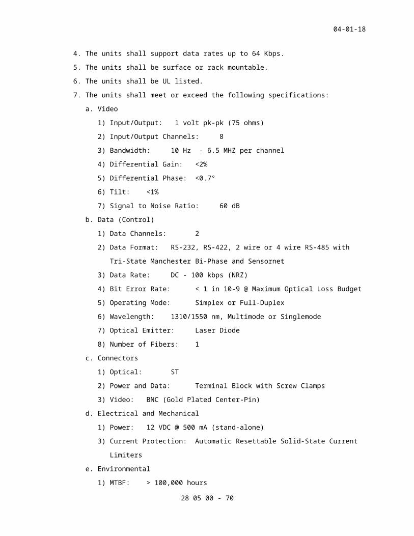
04-01-18
date the Contractor requires it. The Contractor shall not upload
system programming until the Resident Engineer has provided written
approval. The Contractor is responsible for backing up the system
prior to uploading new programming data. Additional programming
requirements are provided as follows:
a. Programming for New SMS Server: The contractor shall provide all
other system related programming. The contractor will be
responsible for uploading personnel information (e.g., ID Cards
backgrounds, names, access privileges, personnel photos, access
schedules, personnel groupings) along with coordinating with
Resident Engineer for device configurations, standards, and
groupings. VA shall provide database to support Contractor’s data
entry tasks. The contractor shall anticipate a weekly
coordination meeting and working with Resident Engineer to ensure
data uploading is performed without incident of loss of function
or data loss.
b. Programming for Existing SMS Servers: The contractor shall
perform all related system programming except for personnel data
as noted. The contractor will not be responsible for uploading
personnel information (e.g., ID Cards backgrounds, names, access
privileges, access schedules, personnel groupings). The contractor
shall anticipate a weekly coordination meeting and working
alongside of Resident Engineer to ensure data uploading is
performed without incident of loss of function or data loss.
System programming for SMS servers shall be performed by using the
Contractor’s own server and software. These servers shall not be
connected to existing devices or systems at any time.
2. The Contractor shall identify and request from the Resident Engineer,
any additional data needed to provide a complete and operational
system as described in the contract documents.
3. Contractor and Resident Engineer coordination on programming requires
a high level of coordination to ensure programming is performed in
accordance with VA requirements and programming uploads do not
disrupt existing systems functionality. The contractor shall
anticipate a minimum a weekly coordination meeting. Contractor shall
ensure data uploading is performed without incident of loss of
function or data loss. The following Level of Effort Chart is
provided to communicate the expected level of effort required by
28 05 00 - 70

04-01-18
contractors on VA ESS projects. Calculations to determine actual
levels of effort shall be confirmed by the contractor before project
award.
Description of Tasks
Description of Systems
Develop System Loading Sheets
Coordination
Initial Set-up Configuration
Graphic Maps
System Programming
Final Checks
Level of Effort (Typical Tasks)
SMS Setup & Configuration
e.g., program monitori
ng stations
, programm
ing networks
, interconnections between CCTV,
intercoms, time synchronization
e.g., retrieve
IP addresse
s, naming conventions,
standard event
descriptions,
programming
templates,
coordinate
special system needs
e.g., Load system Operating System
and Applicat
ion software
, general system configurations
e.g., develop naming conventions, develop file
folders,
confirming
accuracy of
AutoCAD Floor Plans, convert file into jpeg file
e.g.,
program monitoring stations,
programming networks,
interconnections between CCTV,
intercoms, time synchronization
e.g., check all
system diagnostics (e.g., clients,
panels)
Load and set-up 4-6 CDs and
configure servers (to configure Loading and Configuring software
Administrative account, audit
log,Keystrokes, mouse clicks, multi-screen configuration
28 05 00 - 71

04-01-18
Electronic Entry Control Systems
e.g.,
setup of
device,
door
groups &
schedule
s, REX,
Locks,
link
graphics
e.g.,
confirmi
ng
device
configur
ations,
naming
conventi
ons,
event
descript
ion and
narrativ
es
e.g.,
enter
data
from
loading
sheets;
configur
e
componen
ts, link
events,
cameras,
and
graphics
e.g.
,
setu
p of
devi
ce,
door
grou
ps &
sche
dule
s,
REX,
Lock
s,
link
grap
hics
e.g.,
perfor
ming
entry
testin
g to
confir
m
correc
t set-
up and
config
uratio
n
e.g., creating
a door, door
configuration,
adding request
to exit, door
monitors and
relays, door
timers, door
related events
(e.g., access,
access denied,
forced open,
held open),
linkages,
controlled
areas,
advanced door
monitoring,
time zones,
sequence of
operations
28 05 00 - 72

04-01-18
Intrusion Detection Systems
e.g.,
enter
door
groups &
schedule
s, link
devices
- REX,
lock, &
graphics
e.g.,
confirmi
ng
device
configur
ations,
naming
conventi
ons,
event
descript
ion and
narrativ
es
e.g.,
enter
data
from
loading
sheets;
configur
e
componen
ts, link
events,
cameras,
and
graphics
e.g.
,
ente
r
door
grou
ps &
sche
dule
s,
link
devi
ces
-
REX,
lock
, &
grap
hics
e.g.,
walk
test,
device
positi
on,
and
maskin
g
e.g., setting
up monitoring
and control
points (e.g.,
motion
sensors,
glassbreaks,
vibration
sensor,
strobes,
sounders)
creating
intrusion
zones,
creating
arm/disarm
panel, timed
sequences,
time zones,
icon
placements on
graphic maps,
clearance
levels, events
(e.g., armed,
disarmed, zone
violation,
device alarm
activations),
LCD reader
messages,
28 05 00 - 73

04-01-18
CCTV Systems
e.g.,
programm
ing
call-ups
recordin
g
e.g.,
confirmi
ng
device
configur
ations,
naming
conventi
ons
e.g.,
enter
data
from
loading
sheets;
camera
naming
conventi
on,
sequence
s,
configur
e
componen
ts)
e.g.
,
prog
ramm
ing
call
-ups
reco
rdin
g
e.g.,
confir
m area
of
covera
ge,
call-
up per
event
genera
ted
and
record
ing
rates
e.g., setting
up cameras
points,
recording
ratios (e.g.,
normal, alarm
event) timed
recording,
linkages, maps
placements,
call-ups
Intercoms Systems
e.g.,
programm
ing
events &
call-ups
e.g.,
confirmi
ng
device
configur
ations,
naming
conventi
ons,
event
descript
ion and
narrativ
es
e.g.,
enter
data
from
loading
sheets;
configur
e
componen
ts, link
events,
cameras,
and
graphics
e.g.
,
prog
ramm
ing
even
ts &
call
-ups
e.g.,
confir
m
operat
ion,
SMS
event
genera
tion
and
camera
call-
up
e.g., setup
linkages,
events for
activations,
device
troubles, land
devices on
graphic maps
Console Monitoring Components
N/Aper
monitor
per
monitor
per
graphic
map
N/A
per
monito
r
N/A
Note: Programming tasks are supported through the contractor’s development of the Technical Data Package
Submittals.Table 1 Contractor Level of Effort
28 05 00 - 74

04-01-18
3.7 TESTING AND ACCEPTANCE
A. Performance Requirements
1. General:
a. The Contractor shall perform contract field, performance
verification, and endurance testing and make adjustments of the
completed security system when permitted. The Contractor shall
provide all personnel, equipment, instrumentation, and supplies
necessary to perform all testing. Written notification of planned
testing shall be given to the Resident Engineer at least 60
calendar days prior to the test and after the Contractor has
received written approval of the specific test procedures.
b. The COTR shall witness all testing and system adjustments during
testing. Written permission shall be obtained from the Resident
Engineer before proceeding with the next phase of testing.
Original copies of all data produced during performance
verification and endurance testing shall be turned over to the
Resident Engineer at the conclusion of each phase of testing and
prior to Resident Engineer approval of the test.
2. Test Procedures and Reports: The test procedures, compliant w/ VA
standard test procedures, shall explain in detail, step-by-step
actions and expected results demonstrating compliance with the
requirements of the specification. The test reports shall be used to
document results of the tests. The reports shall be delivered to the
Resident Engineer within seven (7) calendar days after completion of
each test.
SPEC WRITER NOTE: Remove Pre-delivery Testing paragraph (B) and all references to pre-delivery testing if Pre-delivery Testing is not required for the Project.
B. Pre-Delivery Testing
1. The purpose of the pre-delivery test is to establish that a system is
suitable for installation. As such, pre-delivery test shall be a
mock-up of the system as planned in the contract documents. The
Contractor shall assemble the Security Test System at the Contractors
local project within 50-miles of the project site, and perform tests
to demonstrate the performance of the system complies with the
contract requirements in accordance with the approved pre-delivery
test procedures. The tests shall take place during regular daytime
working hours on weekdays. Model numbers of equipment tested shall
28 05 00 - 75

04-01-18
be identical to those to be delivered to the site. Original copies
of all data produced during pre-delivery testing, including results
of each test procedure, shall be documented and delivered to the
Resident Engineer at the conclusion of pre-delivery testing and prior
to Resident Engineer’s approval of the test. The test report shall
be arranged so all commands, stimuli, and responses are correlated to
allow logical interpretation. For Existing System modifications, the
contractor shall provide their own server with loaded applicable
software to support PDT.
2. Test Setup: The pre-delivery test setup shall include the following:
a. All console equipment.
1) At least one of each type of data transmission media (DTM) and
associated equipment to provide a fully integrated PACS.
2) The number of local processors shall equal the amount required
by the site design.
3) Enough sensor simulators to provide alarm signal inputs to the
system equal to the number of sensors required by the design.
The alarm signals shall be manually or software generated.
4) Contractor to prove to owner all systems are appropriately
sized and configured as sized.
5) Integration of VASS, intercom systems, other subsystems.
3. During the bidding process the contractor shall submit a request for
information to the Owner to determine if a pre-delivery test will be
required. If a pre-delivery test is not required, the contractor
shall provide a written notification that the Pre-delivery Test is
not required in their shop drawings submission.
SPEC WRITER NOTE: Delete paragraph C. “Intermediate Testing” if not applicable to the project.
//C. Intermediate Testing
1. After completion of 30-50 percent of the installation of ESS
cabinet(s) and equipment, one local and remote control stations and
prior to any further work, this portion of the system must be
pretested, inspected, and certified. Each item of installed
equipment shall be checked to ensure appropriate FCC listing & UL
certification labels are affixed, NFPA, Emergency, Safety, and JCAHCO
guidelines are followed, and proper installation practices are
followed. The intermediate test shall include a full operational
test.//
28 05 00 - 76

04-01-18
D. The inspection and test will be conducted by a factory-certified
contractor representative and witnessed by a Government Representative.
The results of the inspection will be officially recorded by a
designated Government Representative and maintained on file by the
Resident Engineer (RE), until completion of the entire project. The
results will be compared to the Acceptance Test results.
E. Contractor’s Field Testing (CFT)
1. The Contractor shall calibrate and test all equipment, verify DTM
operation, place the integrated system in service, and test the
integrated system. Ground rods installed by this Contractor within
the base of camera poles shall be tested as specified in IEEE STD
142. The Contractor shall test all security systems and equipment,
and provide written proof of a 100% operational system before a date
is established for the system acceptance test. Documentation package
for CFT shall include completed (fully annotated details of test
details) for each device and system tested, and annotated loading
sheets documenting complete testing to Resident Engineer approval.
CFT test documentation package shall conform to submittal
requirements outlined in this Section. The Contractor’s field
testing procedures shall be identical to the Resident Engineer’s
acceptance testing procedures. The Contractor shall provide the
Resident Engineer with a written listing of all equipment and
software indicating all equipment and components have been tested and
passed. The Contractor shall deliver a written report to theResident
Engineer stating the installed complete system has been calibrated,
tested, and is ready to begin performance verification testing;
describing the results of the functional tests, diagnostics, and
calibrations; and the report shall also include a copy of the
approved acceptance test procedure. Performance verification testing
shall not take place until written notice by contractor is received
certifying that a contractors field test was successful.
F. Performance Verification Test (PVT)
1. Test team:
a. After the system has been pretested and the Contractor has
submitted the pretest results and certification to the Resident
Engineer, then the Contractor shall schedule an acceptance test to
date and give the Resident Engineer written, notice as described
herein, prior to the date the acceptance test is expected to
28 05 00 - 77

04-01-18
begin. The system shall be tested in the presence of a Government
Representative, an OEM certified representative, representative of
the Contractor and other approved by the Resident Engineer. The
system shall be tested utilizing the approved test equipment to
certify proof of performance, FCC, UL and Emergency Service
compliance. The test shall verify that the total system meets all
the requirements of this specification. The notification of the
acceptance test shall include the expected length (in time) of the
test.
2. The Contractor shall demonstrate the completed Physical Access
Control System PACS complies with the contract requirements. In
addition, the Contractor shall provide written certification that the
system is 100% operational prior to establishing a date for starting
PVT. Using approved test procedures, all physical and functional
requirements of the project shall be demonstrated and shown. The PVT
will be stopped and aborted as soon as 10 technical deficiencies are
found requiring correction. The Contractor shall be responsible for
all travel and lodging expenses incurred for out-of-town personnel
required to be present for resumption of the PVT. If the acceptance
test is aborted, the re-test will commence from the beginning with a
retest of components previously tested and accepted.
3. The PVT, as specified, shall not begin until receipt of written
certification that the Contractors Field Testing was successful.
This shall include certification of successful completion of testing
as specified in paragraph “Contractor’s Field Testing”, and upon
successful completion of testing at any time when the system fails to
perform as specified. Upon termination of testing by the Resident
Engineer or Contractor, the Contractor shall commence an assessment
period as described for Endurance Testing Phase II.
4. Upon successful completion of the acceptance test, the Contractor
shall deliver test reports and other documentation, as specified, to
the Resident Engineer prior to commencing the endurance test.
5. Additional Components of the PVT shall include:
a. System Inventory
1) All Device equipment
2) All Software
3) All Logon and Passwords
4) All Cabling System Matrices
28 05 00 - 78

04-01-18
5) All Cable Testing Documents
6) All System and Cabinet Keys
b. Inspection
1) Contractor shall record an inspection punch list noting all
system deficiencies. The contractor shall prepare an
inspection punch list format for Resident Engineers approval.
2) As a minimum the punch list shall include a listing of punch
list items, punch list item location, description of item
problem, date noted, date corrected, and details of how item
was corrected.
6. Partial PVT - At the discretion of Resident engineer, the Performance
Verification Test may be performed in part should a 100% compliant
CFT be performed. In the event that a partial PVT will be performed
instead of a complete PVT; the partial PVT shall be performed by
testing 10% of the system. The contractor shall perform a test of
each procedure on select devices or equipment.
G. Endurance Test
1. The Contractor shall demonstrate the specified probability of
detection and false alarm rate requirements of the completed system.
The endurance test shall be conducted in phases as specified below.
The endurance test shall not be started until the Resident Engineer
notifies the Contractor, in writing, that the performance
verification test is satisfactorily completed, training as specified
has been completed, and correction of all outstanding deficiencies
has been satisfactorily completed. VA shall operate the system 24
hours per day, including weekends and holidays, during Phase I and
Phase III endurance testing. VA will maintain a log of all system
deficiencies. The Resident Engineer may terminate testing at any
time the system fails to perform as specified. Upon termination of
testing, the Contractor shall commence an assessment period as
described for Phase II. During the last day of the test, the
Contractor shall verify the appropriate operation of the system.
Upon successful completion of the endurance test, the Contractor
shall deliver test reports and other documentation as specified to
the Resident Engineer prior to acceptance of the system.
2. Phase I (Testing): The test shall be conducted 24 hours per day for
15 consecutive calendar days, including holidays, and the system
shall operate as specified. The Contractor shall make no repairs
28 05 00 - 79

04-01-18
during this phase of testing unless authorized in writing by the
Resident Engineer. If the system experiences no failures, the
Contractor may proceed directly to Phase III testing after receiving
written permission from the Resident Engineer.
3. Phase II (Assessment):
a. After the conclusion of Phase I, the Contractor shall identify all
failures, determine causes of all failures, repair all failures,
and deliver a written report to the Resident Engineer. The report
shall explain in detail the nature of each failure, corrective
action taken, results of tests performed, and recommend the point
at which testing should be resumed.
b. After delivering the written report, the Contractor shall convene
a test review meeting at the job site to present the results and
recommendations to the Resident Engineer. The meeting shall not
be scheduled earlier than five (5) business days after the
Resident Engineer receives the report. As part of this test
review meeting, the Contractor shall demonstrate all failures have
been corrected by performing appropriate portions of the
performance verification test. Based on the Contractor’s report
and the test review meeting, the Resident Engineer will provide a
written determine of either the restart date or require Phase I be
repeated.
4. Phase III (Testing): The test shall be conducted 24 hours per day
for 15 consecutive calendar days, including holidays, and the system
shall operate as specified. The Contractor shall make no repairs
during this phase of testing unless authorized in writing by the
COTR.
5. Phase IV (Assessment):
1. After the conclusion of Phase III, the Contractor shall identify
all failures, determine causes of all failures, repair all
failures, and deliver a written report to the COTR. The report
shall explain in detail the nature of each failure, corrective
action taken, results of tests performed, and recommend the point
at which testing should be resumed.
2. After delivering the written report, the Contractor shall convene
a test review meeting at the job site to present the results and
recommendations to the COTR. The meeting shall not be scheduled
earlier than five (5) business days after receipt of the report by
28 05 00 - 80

04-01-18
the COTR. As a part of this test review meeting, the Contractor
shall demonstrate that all failures have been corrected by
repeating appropriate portions for the performance verification
test. Based on the review meeting the test should not be
scheduled earlier than five (5) business days after the Resident
Engineer receives the report. As a part of this test review
meeting, the Contractor shall demonstrate all failures have been
corrected by repeating appropriate portions of the performance
verification test. Based on the Contractor’s report and the test
review meeting, the Resident Engineer will provide a written
determine of either the restart date or require Phase III be
repeated. After the conclusion of any re-testing which the
Resident Engineer may require, the Phase IV assessment shall be
repeated as if Phase III had just been completed.
H. Exclusions
1. The Contractor will not be held responsible for failures in system
performance resulting from the following:
a. An outage of the main power in excess of the capability of any
backup power source provided the automatic initiation of all
backup sources was accomplished and that automatic shutdown and
restart of the PACS performed as specified.
b. Failure of an Owner furnished equipment or communications link,
provided the failure was not due to Contractor furnished
equipment, installation, or software.
c. Failure of existing Owner owned equipment, provided the failure
was not due to Contractor furnished equipment, installation, or
software.
- - - E N D - - -
28 05 00 - 81