section 4 - neopost technologies 4 - 1 as900 pressure sealer section 4 operating and service...
TRANSCRIPT
Page 4 - 1
AS900 PRESSURE SEALER �����������
SECTION 4
OperatingandServiceAdjustments
ISSUE 1APR 2003

Page 4 - 2
�����������AS900 PRESSURE SEALER
4.1 SERVICE CHECK LIST
1. Unplug power cord.2. Remove covers.3. Check all screws for tightness.4. Check infeed rollers for wear and operation. Replace if required.5. Clean infeed rollers.6. Check operation of separator roller mechanism, including increment stop.7. Check separator roller for wear. Adjust or replace if required.8. Check separator roller mechanism for tightness.9. Check all feed rollers and wheels for wear. Replace if required.10. Clean all feed rollers and wheels.11. Clean pressure rollers.12. Lubricate 8 needle roller bearings on pressure roller journals using light machine
oil (remove drive pulley & roller gears on drive side of machine to gain access).13. Check gear drive train for wear. Lubricate.14. Check diverter mechanism for smooth operation. Ensure all diverters are aligned.15. Check diverter solenoid is actuating correctly, and also releasing.16. Check side guide operation and alignment.17. Clean all sensors with air duster or air compressor.18. Check security of PCB connectors.19. Check security of power cord plug.20. Switch on machine.21. Check and test all sensor settings.22. Feed through paper to check unit function.23. Check correct function of output conveyor.24. Check cover microswitch operation.25. Switch off main machine.26. Refit covers.27. Clean unit as required.
Note: rubber rollers and wheels should be cleaned using only PFE RollerCleaning Fluid A0037A except for infeed pickup roller, which should be cleaned using acloth dampened with water. Spirit based or other cleaners may not sufficiently removeimpacted residues. Pressure rollers should be cleaned using Isopropyl Alcohol, oralcohol based cleaner.
ISSUE 1APR 2003

Page 4 - 3
AS900 PRESSURE SEALER �����������
4.2 SERVICING AND ADJUSTMENTS
4.2.1 SEPARATOR GRIP ROLLER
FIG.1
The separator grip roller is set via the control knob (see Fig.1 above) to allow only one formthrough at a time. As the roller wears, a flat occurs across the face. This is corrected by liftingsetting peg and rotating the roller one stop to clear the worn section. When all stop positionshave been used, the roller must be replaced.
To replace the roller, remove the separator unit complete with feed wheel shaft. The adjacentsensor shaft will have to be slackened and moved to allow withdrawal of the separator assem-bly. Exercise great care to avoid straining the wires. Strip the assembly to remove the roller(exploded view, section 5.4 may assist). Note that the roller pivot shaft is in two halves, heldtogether with a set screw.
After reassembly, ensure that the hold-point sensor is correctly adjusted - see section 4.3.1,'Adjustment of Sensors'.
Setting Peg C2186EControl KnobE0113A
Separator Grip Roller C8071A
ISSUE 1APR 2003

Page 4 - 4
�����������AS900 PRESSURE SEALER
4.2.2 DIVERTER ADJUSTMENT
Open position
Clearance
Closed position
Clearance Adjustment screwE2537A
Pressure rollerC8058A
Feed rollerC8056A
FIG. 2
The diverters should be adjusted to meet the conditions shown in Fig.2 above. A clearance of.005" (.13mm) must exist between the leading tip of diverter and feed roller when closed, andbetween trailing tip and pressure roller when open. All diverters must be in line on the shaft.
To adjust the diverters proceed as follows:
1. Move the solenoid bracket fully forward.2. Slacken the diverter srews to adjust the solenoid lever to approx. 10º past right
angle to the solenoid centre line, with the diverter tips just touching the roller intheir closed position (see Fig. 3 below).
3. Turn in a piece of paper by hand so that it passes under the diverters.4. Slide the solenoid bracket back (so opening the diverters) until it just touches the
paper at the tips in the closed position (see Fig. 2 above).5. Slide the solenoid on its bracket to the setting shown in Fig. 3.6. Open the diverters to check clearance in the open position (see Fig. 2 above).
Note: if a diverter screw is replaced for any reason, the threads must be greased using a gen-eral purpose grease.
FIG. 3
Solenoid bracketB2650C
Solenoid leverB2561A
APPROX. 10º
.22" -.24"(5.6 - 6.1mm)
Solenoid179-305
ISSUE 1APR 2003

Page 4 - 5
AS900 PRESSURE SEALER �����������
4.2.3 SENSOR ALIGNMENT
The hold point, folder input, double document, folder output and output sensors are attachedto cross shafts, either in holders or drilled through. In the case of the holder mounted sensors,they should be adjusted so that their length is parallel with the top surface of the unit, and themachined portion is rotationally positioned horizontally on the shaft. (See Fig.4a above). Thedrilled through sensors should be rotationally adjusted so that the optical path between trans-mitter and receiver is aligned (see Fig.4b above). To confirm correct operation of sensors, seesection 4.3.1, 'Adjustment of Sensors'.
Sensorholder
Fig. 4a Fig. 4b
4.2.4 PRESSURE ROLLER GAP
Folder Side Roller Output Side Roller
FIG. 5
The pressure rollers are factory set and should not normally require attention. However,should this be necessary for any reason, proceed as described .
Receiver
Transmitter
ISSUE 1APR 2003
Page 4 - 6
�����������AS900 PRESSURE SEALER
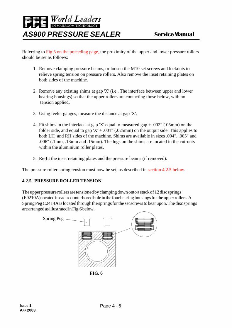
Referring to Fig.5 on the preceding page, the proximity of the upper and lower pressure rollersshould be set as follows:
1. Remove clamping pressure beams, or loosen the M10 set screws and locknuts to relieve spring tension on pressure rollers. Also remove the inset retaining plates on both sides of the machine.
2. Remove any existing shims at gap 'X' (i.e.. The interface between upper and lower bearing housings) so that the upper rollers are contacting those below, with no tension applied.
3. Using feeler gauges, measure the distance at gap 'X'.
4. Fit shims in the interface at gap 'X' equal to measured gap + .002" (.05mm) on the folder side, and equal to gap 'X' + .001" (.025mm) on the output side. This applies to both LH and RH sides of the machine. Shims are available in sizes .004", .005" and .006" (.1mm, .13mm and .15mm). The lugs on the shims are located in the cut-outs within the aluminium roller plates.
5. Re-fit the inset retaining plates and the pressure beams (if removed).
The pressure roller spring tension must now be set, as described in section 4.2.5 below.
4.2.5 PRESSURE ROLLER TENSION
The upper pressure rollers are tensioned by clamping down onto a stack of 12 disc springs(E0210A) located in each counterbored hole in the four bearing housings for the upper rollers. ASpring Peg C2414A is located through the springs for the set screws to bear upon. The disc springsare arranged as illustrated in Fig.6 below.
Spring Peg
FIG. 6
ISSUE 1APR 2003
Page 4 - 7
AS900 PRESSURE SEALER �����������
Tension is adjusted via the M10 set screws acting on the disc springs. Initially, the screws areset by turning downwards until contact is just made with the springs, then adding a further 1/2turn. Tighten the locknuts, then start the machine and run several forms through to confirmthat they are correctly sealed. If not, each of the sets screws must be tightened down by afurther 1/8th turn at a time until effective form sealing is achieved. Ensure that all locknuts areretightened afterwards.
Note: if, after adjustment, the motor speed is heard to fluctuate when running forms, thepressure being applied may be too great and should be reduced.
MCP pressure sensitive test paper should be run through the machine to check that pressure isequally exerted on both sides. If the test paper is darker on one side, then the roller pressureshould be reduced on that side. Back off the screws on that side 1/8th turn at a time until thetest paper shows a consistent shade.
4.2.6 INFEED RESTRICTOR ADJUSTMENT
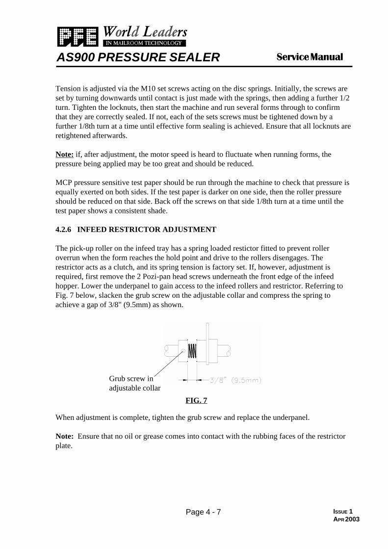
The pick-up roller on the infeed tray has a spring loaded restictor fitted to prevent rolleroverrun when the form reaches the hold point and drive to the rollers disengages. Therestrictor acts as a clutch, and its spring tension is factory set. If, however, adjustment isrequired, first remove the 2 Pozi-pan head screws underneath the front edge of the infeedhopper. Lower the underpanel to gain access to the infeed rollers and restrictor. Referring toFig. 7 below, slacken the grub screw on the adjustable collar and compress the spring toachieve a gap of 3/8" (9.5mm) as shown.
When adjustment is complete, tighten the grub screw and replace the underpanel.
Note: Ensure that no oil or grease comes into contact with the rubbing faces of the restrictorplate.
Grub screw inadjustable collar
FIG. 7
ISSUE 1APR 2003

Page 4 - 8
�����������AS900 PRESSURE SEALER
4.3 ELECTRONICS AND SOFTWARE
4.3.1 ADJUSTMENT OF SENSORS
All voltage adjustments to be made with respect to TP10 (0v) on the CPU PCB.
Connector J1 - Form Length SensorAdjust VR8 to give 0.25v to 0.35v between TP1 and 0v with sensor clear.Now turn sensor disc to blocked positionConfirm >3.5v (blocked) between TP1 and 0v
Connector J2 - Hold Point SensorAdjust VR1 to give 0.25v to 0.35v between TP2 and 0v with sensor clear of paper.Now put 20 lbs bond (80gsm) paper between sensors to block fully.Confirm >3.5v (blocked) between TP2 and 0v
Connector J3 - Folder Output SensorAdjust VR2 to give 0.25v to 0.35v between TP3 and 0v with sensor clear of paper.Now put 20 lbs bond (80gsm) paper between sensors to block fully.Confirm >3.5v (blocked) between TP3 and 0v
Connector J4 - Divert SensorAdjust VR3 to give 0.25v to 0.35v between TP4 and 0v with sensor clear of paper.Now put 20 lbs bond (80gsm) paper between sensors to block fully.Confirm >3.5v (blocked) between TP4 and 0v
Connector J5 - Output SensorAdjust VR4 to give 0.25v to 0.35v between TP5 and 0v with sensor clear of paper.Now put 20 lbs bond (80gsm) paper between sensors to block fully.Confirm >3.5v (blocked) between TP5 and 0v
Connector J6 - Conveyor Full Switch (High Capacity Conveyor)No adjustment. Check >3.5v (switch open) and <0.55v (switch closed) between TP6and 0v.
Connector J7 - Folder Input SensorAdjust VR5 to give 0.25v to 0.35v between TP7 and 0v with sensor clear of paper.Now put 20 lbs bond (80gsm) paper between sensors to block fully.Confirm >3.5v (blocked) between TP7 and 0v
ISSUE 1APR 2003

Page 4 - 9
AS900 PRESSURE SEALER �����������
Connector J8 - Conveyor Jog Switch (High Capacity Conveyor)Adjust VR7 to approximately mid-position. Check >3.5v (switch open) and <0.55v(switch closed) between TP11 and 0v.
Connector J9 - Doubles DetectorLED (D12) onlyPut 4 thicknesses of 20 lbs bond (80gsm) paper between the sensors and hold down withpressure wheel. Turn VR6 clockwise until D12 just comes on. Alternatively, if D12 isalready on, turn VR6 anticlockwise until D12 goes off, then clockwise until it comes on.Ensure that both doubles-detector and folder input sensors are blocked with paper.
Note: to adjust the doubles Detector, test 3 of the Engineer Service Mode must beentered. This is fully described in section 4.3.3
ISSUE 1APR 2003
Page 4 - 10
�����������AS900 PRESSURE SEALER
Sensor adjustments can be confirmed via LEDBAR1 on the CPU PCB. With voltage low(sensor clear) the relevant LED will light. With voltage high (sensor blocked) the relevantLED will not light. The relevant LED's are as follows:-
LEDBAR1 LED1 Form Length SensorLED2 Hold Point SensorLED3 Folder Output SensorLED4 Divert SensorLED5 Output SensorLED6 Conveyor Full SwitchLED7 Folder Input SensorLED8 Conveyor Jog SwitchLED9 Cover 1LED10 Cover 2
Similarly, the operation of various machine functions can be checked via LEDBAR2. Therelevant LED will light when voltage is applied to the items indicated, even if those items failto activate for any reason. The relevant LED's are:
LEDBAR2 LED1 Feed Roller clutchLED2 Brake (not fitted)LED3 Diverter SolenoidLED4 N/ALED5 N/ALED6 N/ALED7 Motor in forward (drive) directionLED8 Motor onLED9 N/ALED10 N/A
4.3.2 SETTING OF DIP SWITCH.The DIP switch (S1) on the CPU board may set for the following:
Switch 1 - ON = Auto-calibrate on power up/hopper empty (Default OFF)Switch 2 - ON = Stop machine after 2 consecutive doubles (Default OFF)Switch 3 - ON = Engineer Service Mode enabledSwitch 4 - Not for use (OFF at all times)
See Fig. 8, Section 4.3.4 for position of DIP switch on CPU PCB.
ISSUE 1APR 2003

Page 4 - 11
AS900 PRESSURE SEALER �����������
4.3.3 ENGINEER SERVICE MODE
ENTERING ENGINEER SERVICE MODE
1. Switch machine off at power switch.2. Set DIP switch S1,3 to ON.3. Switch machine on.4. The following key sequence must be executed while the display
is showing “HELLO 4100”, and steps 5 to 7 must be completedwithin two seconds.
5. Press STOP and JOG FORWARD keys simultaneously.6. Press RESET OUT count key.7. Press RESET IN count key.8. The message “Eng Ser” will appear on the display if the above
key sequence has been entered correctly and within 2 seconds.9. Pressing the JOG FORWARD key steps through the engineer service
facilities described below.
ENGINEER SERVICE FACILITIES
1. Software version. This is the EPROM version fitted.Display shows “VER N-NN”.
2. Hour count. This is the total number of hours the machine hashas been run since production.Display shows the hour count to one tenth hour resolution:
“Hour HHHH.H”
3. Total document count. This is the total number of documentsprocessed since production.Display shows ten digit count “NNNNN NNNNN”.
4. Test 1 - Lamp test.Display shows “TEST 1”. Press GO key to execute test 1.This test flashes every led on the control panel. Exited bypressing the STOP key (returns to "TEST 1" display).
5. Test 2 - Control panel test.Display shows “TEST 2”. Press GO key to execute test 2.This test acknowledges each key press with appropriate message.Exited by pressing STOP and SETUP keys simultaneously (returnsto "TEST 2" display).
ISSUE 1APR 2003

Page 4 - 12
�����������AS900 PRESSURE SEALER
6. Test 3 - Mechanism test.Displays shows “TEST 3”. Press GO key to execute test 3.This test exercises the mechanical parts of the machine othertests can’t reach. Also, doubles detector sensor test is carriedout in while in test 3. Press GO key to execute test 3, STOPand SETUP keys to exit test 3 (returns to "TEST 3" display).
6.1 Motor Test & Speed Setting
� GO/STOP keys turn motor on/off.� -/+ keys change motor speed.� JOG FORWARD/JOG REVERSE set motor direction
FORWARD/REVERSE but only actioned with the motor stopped.� RESET IN key display the speed of the rollers in rpm. This
display will be over-ridden if another key is pressed. Set machinespeed using VR3 & VR6 on PSU PCB as shown below:
Using + button, select Speed 9. Set max. top speed usingVR3 to read 258 ± 10 on display.Using - button, select Speed 0. Set min. low speed usingVR6 to read 200 ± 10 on display.
Re-check max. top speed and set again if it has altered. Fig. 9 insection 4.3.4 shows the positions of the pots on the PSU PCB.
� Cover switches should prevent motor from running when open.
6.2 Clutch Test
� SETUP key pulses the clutch for approx 200 millisecs.� HANDFEED key toggles the clutch ON/OFF.
6.3 Divert Test
� RESET OUT key toggles divert solenoid ON/OFF.
EXITING ENGINEER SERVICE MODE
Press STOP and SETUP keys simultaneously to exit.
ISSUE 1APR 2003

Page 4 - 13
AS900 PRESSURE SEALER �����������
CPU PCB180-138
FIG. 8
For circuit diagrams and component items lists of all circuit boards, refer to section 6 of thismanual.
4.3.4 PHYSICAL LAYOUTS OF PCBs
ISSUE 1APR 2003

Page 4 - 14
�����������AS900 PRESSURE SEALER
Refer to Fig.8 below for physical layout of Speed Control/PSU PCB
SPEED CONTROL/PSU PCB180-135/6 (220V/110V)
FIG. 10
Refer to Fig.9 below for physical layout of Control Panel PCB
FIG. 9
CONTROLPANEL PCB
180-137
ISSUE 1APR 2003

Page 4 - 15
AS900 PRESSURE SEALER �����������
4.3.5 RECOMMENDED SPARES (MECHANICAL)
Shown below are mechanical spare parts recommended to be held at National, Depot andLocal levels. Note that some items are voltage specific.
Quantities indicated are for every 10 machines (up to).
PARTNUMBER
DESCRIPTION QTY
179-050 PM63/50 195V MOTOR (220V MACHINES) 1
179-051 PM63/50 95V MOTOR (110V MACHINES) 1
181-111 CLUTCH, LENZE TYPE 1
179-305 SOLENOID BDCAL 24V 1
B0053A ANTI-STATIC BRUSH 1
B0056A ANTI-STATIC BRUSH 1
B1421C OUTFEED GUIDE, UPPER 1
C0037A THRUST WASHER 8
C8071A SEPARATOR ROLLER 1
C7167A PRESSURE BEAM, LH 1
C7168A PRESSURE BEAM, RH 1
C2412A FEED WHEEL CORE, 12mm BORE 6
C8049A FEED ROLLER 9
C2413A FEED WHEEL CORE, 18mm BORE 2
C8051A PICK-UP ROLLER 2
C2411A FEED WHEEL CORE, 8mm BORE 6
C8056A UPPER FOLD ROLLER 3
C8057A LOWER FOLD ROLLER 2
A0177A PRESSURE ROLLER ASSEMBLY 4
E1000A 17mm BALL BEARING 2
E1001A 15mm BALL BEARING 1
E1029A 12mm x 18mm x 16mm ROLLER CLUTCH 4
E1030A 8mm x 12mm x 12mm ROLLER CLUTCH 4
E1038A 8mm x 12mm x 12mm PL. OILITE 2
E1039A 8mm BALL BEARING 2
E1054A 12mm BALL BEARING 11
D0017A FEED WHEEL TYRE 14
ISSUE 1APR 2003

Page 4 - 16
�����������AS900 PRESSURE SEALER
Recommended Spares (Mechanical) contd.
PARTNUMBER
DESCRIPTION QTY
F4084A FOLD GEAR, 20T 2
F5032A S4.5M 450 x 25 100T BELT 2
F5060A S4.5M 396 x 25 88T BELT 2
G0043A SOLENOID LINK 1
G1024A RETURN SPRING 2
G1025A PRESSURE SPRING 4
G1026A FOLD ROLLER SPRING 2
G1053A FOLD ROLLER SPRING 8
G1054A HOLDER SPRING 4
G1062A RESTRICTOR SPRING 1
G4005A 'T' BEARING HOUSING 10
G6091A SHIM (.004") 12
G6092A SHIM (.005") 6
G6093A SHIM (.006") 6
F4095A PINION 1
G5014A BELT, 892.5 x 25mm 2
D0005A JOGGLER TYRE 4
E0210A DISC SPRING 96
C2414A SPRING PEG 8
ISSUE 1APR 2003

Page 4 - 17
AS900 PRESSURE SEALER �����������
4.3.6 RECOMMENDED SPARES (ELECTRICAL)
Shown below are electrical spare parts recommended to be held at National, Depot and Locallevels. Note that some items are voltage specific.
Quantities indicated are for every 10 machines (up to).
PARTNUMBER
DESCRIPTION QTY
180-663 CPU PCB 1
180-661 SPEED CONTROL/PSU PCB (220V) 1
180-662 SPEED CONTROL/PSU PCB (110V) 1
180-137 CONTROL PANEL PCB 1
180-664 AC MOTOR SWITCH PCB 1
123-326 PROGRAMMED EPROM, 27C128 P.S. 1
123-021 PROGRAMMED PAL, 16L8 P.S. 1
182-166 16-WAY RIBBON CABLE ASSEMBLY 1
182-165 14-WAY RIBBON CABLE ASSEMBLY 1
168-318 MAINS INPUT UNIT/FILTER 1
131-815 STOP SWITCH, N/C 1
131-106 ROLL COVER SWITCH 1
182-168 SENSOR ASSY. SET P/SEALER 1
117-231 PHOTO DIODE ASSY. TIL 143 1
182-072 WIRED MAGNETIC REED SWITCH ASSY. 1
131-806 MAGNET FOR REED SWITCH 1
162-210 MAINS LEAD, 10A MOULDED, 2.5m (220V) 1
162-321 MAINS LEAD, 10A UL PK1-IEC320 SJT (110V) 1
135-103 FUSE, 20mm 3.15A (220V) 20
135-106 FUSE, 20mm 6.3A (110V) 20
ISSUE 1APR 2003

Page 4 - 18
�����������AS900 PRESSURE SEALER
ISSUE 1APR 2003
Blank Page