section 7 interchanges - state
TRANSCRIPT
BDC08MR-01
NJDOT Design Manual–Roadway 7-1 Interchanges
Section 7
Interchanges
7.1 General
The capacity of arterial highways, particularly in urban areas, to handle high volumes of traffic safely and efficiently depends, to a considerable extent, upon their ability to accommodate crossing and turning movements at intersecting highways. The greatest efficiency, safety and capacity are attained when the intersecting through traffic lanes are grade separated.
An interchange is a system of interconnecting roadways in conjunction with one or more grade separations, providing for the movement of traffic between two or more roadways on different levels. Safety and traffic capacity are increased by the provision of interchanges. Crossing conflicts are eliminated by grade separations. Turning conflicts are either eliminated or minimized, depending upon the type of interchange design.
One intent of this section is that except in the most extreme circumstances, all new interchanges should provide for all movements. However, it is recognized that circumstances may exist when initial construction of only part of an interchange might be appropriate. Where such circumstances exist, commitments must be made, possibly even purchase of necessary right-of-way during the initial project stage for future completion.
7.2 Warrants for Interchanges
7.2.1 Freeways and Interstate Highways
Interchanges should be provided on Interstate highways and freeways at all intersections where access is to be permitted. Other intersecting roads or streets are either grade separated, terminated, or rerouted.
7.2.2 Other Highways
On highways with only partial control or no control of access, definite warrants cannot be specified as they may differ at each location. The following factors should be considered in analyzing a particular situation:
1. Design Designation
The determination to develop a highway with full control of access between selected terminals becomes the warrant for providing a highway grade separation. Once the decision is made to develop a route as a freeway, it should be determined whether each intersection highway will be terminated, rerouted, or provided with a grade separation or interchange. The major concern is the continuous flow on the major road. An intersection that might warrant only traffic signal control, if considered as an isolated case, will warrant a grade separation or interchange when considered as a part of a freeway.
2. Reduction of Congestion
Insufficient capacity at the intersection of heavily traveled highways results in intolerable delays and congestion in one or all approaches. The inability to provide the essential capacity with an intersection at grade provides the warrant for an interchange.
3. Improvement of Safety
Some intersections at grade have a high accident rate even though serving light traffic volumes. Other more heavily traveled intersections have a history

BDC08MR-01
NJDOT Design Manual–Roadway 7-2 Interchanges
of serious accidents. If the safety at such intersections cannot be improved by more inexpensive methods, construction of an interchange facility may be warranted.
4. Site Topography
At some sites, the topographic conditions may be such that the provisions of an interchange facility may entail no more cost than an at-grade intersection.
5. Traffic Volume
For a new intersection under design, an interchange would be warranted where a capacity analysis indicates that an at-grade design cannot satisfactorily serve, without undue delay and congestion, the traffic volumes and turning movements expected.
6. Road-user Benefits
Road-user costs include fuel and oil usage, wear on tires, repairs, delay to motorists and crashes as a result of speed changes, stops and waiting. Road user costs at congested at-grade intersections are well in excess of those for intersections permitting uninterrupted or continuous operation. Interchanges may involve more total travel distance than at grade crossings, but the added cost of the extra travel distance is less than the cost savings resulting from the reduction in stopping and delay. The relation of road-user benefits to the cost of improvement indicates an economic warrant for that improvement.
7.3 Interchange Types
7.3.1 General
The selection of an interchange type and its design are influenced by many factors, including the following: the highway classification, design speed, volume and composition of traffic to be served, the number of intersecting legs, the standards and arrangement of the local street system including traffic control devices, topography, right-of-way controls, local planning, proximity of adjacent interchanges, community and environmental impact consideration and cost. Even though interchanges are, of necessity, designed to fit specific conditions and controls, it is desirable that the pattern of interchange ramps along a freeway follow some degree of consistency. It is frequently desirable to rearrange portions of the local street system in connection with freeway construction in order to effectuate the most desirable overall plan of traffic service and community development.
The use of isolated ramps or partial interchanges should be avoided because wrong-way movements are more prevalent at isolated off-ramps and there is less confusion to motorists where all traffic movements are provided at an interchange. In general, interchanges with all ramps connecting with a single cross street are preferred.
Interchange types are characterized by the basic shapes of ramps: namely; diamond, loop, directional or variations of these types. Many interchange designs are combinations of these basis types.
7.4 Interchange Design Elements
7.4.1 General
Geometric design for all interchange roadways should follow the design guides as covered in Section 4, "Basic Geometric Design Elements."
7.4.2 Spacing
The minimum spacing of interchanges for proper signing on the main road should be at least 1 mile between urban crossroads and 2 miles along rural sections. In urban

BDC08MR-01
NJDOT Design Manual–Roadway 7-3 Interchanges
areas, spacing of less than 1 mile may be developed by using grade separated ramps or by adding collector-distributor roads. Closely spaced interchanges interfere with free traffic flow and safety, even with the addition of extra lanes, because of insufficient distance for weaving maneuvers. During the early design stage, the Bureau of Traffic Signals and Safety Engineering should be consulted to assure that proper signing of the interchange is possible.
7.4.3 Sight Distance
Sight distance along the through roadways and all ramps should be at least equal to the minimum safe stopping sight distance and preferably longer for the applicable design speed. See Sections 4 & 6 for sight distance requirements.
7.4.4 Alignment, Profile and Cross Section
Traffic passing through an interchange should be provided the same degree of utility and safety as on the approaching highways. The standards for design speed, alignment, profile and cross section for the main lanes through the interchange area should be as high as on the approach legs. Desirably, the alignment and profile of the through highways at an interchange should be relatively flat with high visibility. The full roadway cross section should be continued through the interchange area and adequate clearances provided at structures.
7.5 Ramps
7.5.1 General
The term "ramp" includes all types, arrangements, and sizes of turning roadways that connect two or more legs at an interchange. The components of a ramp are a terminal at each end and a connecting road, usually with some curvature, and on a grade. Ramps are one way roadways.
7.5.2 Ramp Capacity
The capacity of a ramp is generally controlled by one of its terminals. Occasionally the ramp proper determines the capacity, particularly where speeds may be significantly affected by curvature, grades, and truck operations. Figure 7-A shows the basic values (Service Volumes) for the ramp proper on single lane ramps.
7.5.3 Design Speed
It is not practical to provide design speeds on ramps that are comparable to those on the through roadways. Ramp design speeds however should not be less than 25 mph. On cloverleaf interchanges, the outer connections should desirably be designed for 35 mph.
Recommended ramp design speeds for various ramp configurations are as follows: Loop ramps, 25 mph; semidirect, 30 mph; and direct connections, 40 mph.
7.5.4 Grades
Ramp grades should be as flat as feasible to minimize driving effort required in maneuvering from one road to another. On one-way ramps, a distinction can and should be made between upgrades and downgrades. As general criteria, it is desirable that maximum upgrades on ramps be limited to the following:

BDC08MR-01
NJDOT Design Manual–Roadway 7-4 Interchanges
Table 7-1
Upgrades on Ramps
Design
Speed
(mph)
Maximum
Upgrade
Range
(Percent)
45 – 50
3 - 5
35 – 40
4 - 6
25 – 30
5 - 7
15 – 25
6 - 8
Minimum ramp grades should not be less than 0.3 percent. One way downgrades on ramps should be held to the same general maximums, but in special cases they may be 2 percent greater. When the ramp is to be used predominately by truck traffic (many heavy trucks), one-way upgrades should be limited to 5 percent. One-way downgrades should be limited to 3-4 percent on ramps with sharp horizontal curves and for heavy truck or bus traffic.
7.5.5 Sight Distance
On ramps, no planting of vegetation that would restrict the sight distance to less than the minimum for the applicable design speed shall be permitted.
7.5.6 Widths
Figure 7-B illustrates the desired ramp widths for various ramp curvatures. Single lane ramp widths will be based on Case II for the ramp proper and Case I at the entrance terminal. Case III should be used in determining ramp widths on two lane ramps. See Section 5, Figure 5-J for typical single and two lane ramp sections.
7.5.7 Location of Ramp Intersection on Cross Road
Factors which influence the location of ramp intersections on the cross road include sight distance, construction and right-of-way costs, circuity for left turn movements, cross road gradient at ramp intersections, storage requirements for left turn movements off the cross road, and the proximity of other local road intersections.
For left maneuvers from an off ramp at an unsignalized intersection, the length of cross road open to view should be greater than the product of the design speed of vehicles on the cross road and the time required for a stopped vehicle on the ramp to safely execute a left turn maneuver. See Section 6 for sight distance at intersections.
Where design controls prevent locating the ramp terminal a sufficient distance from the structure to achieve the required sight distance, the sight distance should be obtained by flaring the end of the overcrossing structures or setting back the piers or end slopes of an undercrossing structure.
Sharp curves at an off ramp terminal (at the intersection with the local street) should be avoided, even if such an intent is to provide an acceleration lane for merging into the local street traffic. It is often better to provide a near 90 degree intersection with stop sign control. Slip ramps from the freeway to a local parallel two-way street should also be discouraged because of limited sight distance usually encountered at the merge with the local street traffic.

NJDOT Design Manual–Roadway 7-5 Interchanges

NJDOT Design Manual–Roadway 7-6 Interchanges
BDC08MR-01
NJDOT Design Manual–Roadway 7-7 Interchanges
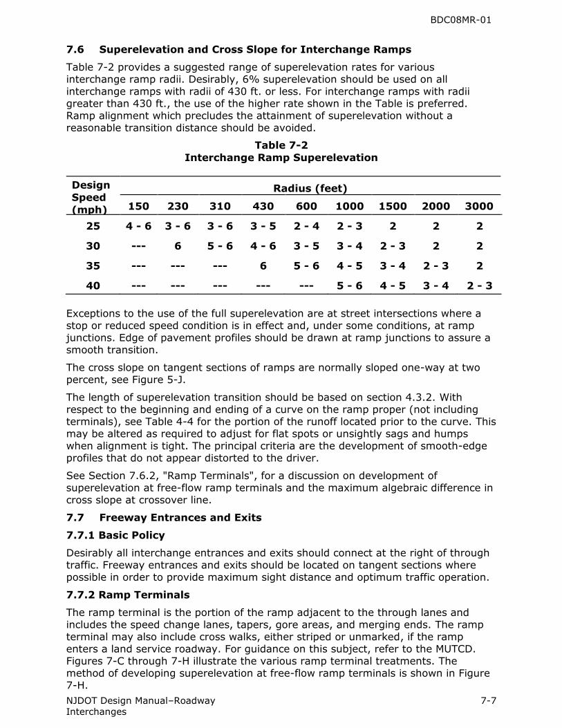
7.6 Superelevation and Cross Slope for Interchange Ramps
Table 7-2 provides a suggested range of superelevation rates for various interchange ramp radii. Desirably, 6% superelevation should be used on all interchange ramps with radii of 430 ft. or less. For interchange ramps with radii greater than 430 ft., the use of the higher rate shown in the Table is preferred. Ramp alignment which precludes the attainment of superelevation without a reasonable transition distance should be avoided.
Table 7-2
Interchange Ramp Superelevation
Design
Speed
(mph)
Radius (feet) 150
230
310
430
600
1000
1500
2000
3000
25
4 - 6
3 - 6
3 - 6
3 - 5
2 - 4
2 - 3
2
2
2
30
---
6
5 - 6
4 - 6
3 - 5
3 - 4
2 - 3
2
2
35
---
---
---
6
5 - 6
4 - 5
3 - 4
2 - 3
2
40
---
---
---
---
---
5 - 6
4 - 5
3 - 4
2 - 3
Exceptions to the use of the full superelevation are at street intersections where a stop or reduced speed condition is in effect and, under some conditions, at ramp junctions. Edge of pavement profiles should be drawn at ramp junctions to assure a smooth transition.
The cross slope on tangent sections of ramps are normally sloped one-way at two percent, see Figure 5-J.
The length of superelevation transition should be based on section 4.3.2. With respect to the beginning and ending of a curve on the ramp proper (not including terminals), see Table 4-4 for the portion of the runoff located prior to the curve. This may be altered as required to adjust for flat spots or unsightly sags and humps when alignment is tight. The principal criteria are the development of smooth-edge profiles that do not appear distorted to the driver.
See Section 7.6.2, "Ramp Terminals", for a discussion on development of superelevation at free-flow ramp terminals and the maximum algebraic difference in cross slope at crossover line.
7.7 Freeway Entrances and Exits
7.7.1 Basic Policy
Desirably all interchange entrances and exits should connect at the right of through traffic. Freeway entrances and exits should be located on tangent sections where possible in order to provide maximum sight distance and optimum traffic operation.
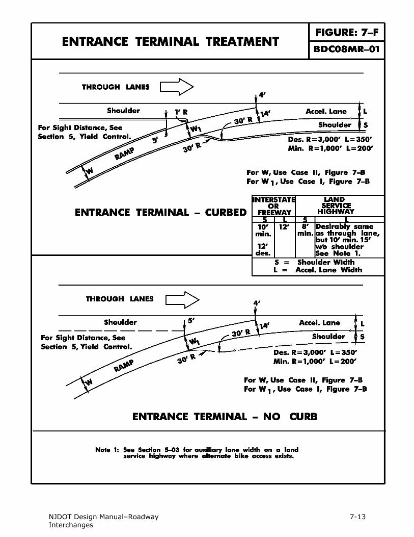
7.7.2 Ramp Terminals
The ramp terminal is the portion of the ramp adjacent to the through lanes and includes the speed change lanes, tapers, gore areas, and merging ends. The ramp terminal may also include cross walks, either striped or unmarked, if the ramp enters a land service roadway. For guidance on this subject, refer to the MUTCD. Figures 7-C through 7-H illustrate the various ramp terminal treatments. The method of developing superelevation at free-flow ramp terminals is shown in Figure 7-H.

BDC08MR-01
NJDOT Design Manual–Roadway 7-8 Interchanges
Figure 7-H schematic 1 shows a deceleration lane type exit on a tangent section of highway that leads into a flat existing curve. At Point B, the normal crown of the through roadway is projected onto the auxiliary pavement. At Point C, the crown line can be gradually changed to start the development of superelevation for the exiting curve. At Point D, two breaks in the crossover crown line in the painted gore would be conducive to developing a full superelevation in the vicinity of the physical nose.
Figure 7-H schematic 2 shows a deceleration lane type exit on a curved section of highway. The superelevation of the highway would be projected onto the auxiliary pavement.
Figure 7-H schematic 3 shows an acceleration lane type entrance on the high side of a superelevated horizontal curve. At Point D, the ramp superelevation would be close to zero and full superelevation would be attained at Point C.
Figure 7-H schematic 4 shows a typical cloverleaf entrance and exit on a tangent section of highway that leads into sharp curvature developing in advance of the physical nose. Part of the cross slope change can be attained over the length of the parallel auxiliary lane with about half of the total superelevation being attained at Point B. Full superelevation of the ramp proper is reached beyond the physical nose.
Superelevation transition should not exceed a maximum distribution rate of two percent per second of time for the design speed. Also, the suggested maximum differences in cross slope rates at the crossover crown line, related to the speed of turning traffic, should not exceed the values shown in Table 7-3. The design control at the crossover crown line is the algebraic difference in cross slope rates of the ramp terminal pavement and the adjacent mainline pavement. A desirable maximum difference at a crossover line is 4 to 5 percent.
Table 7-3
Maximum Differences in Cross Slope
Rates at the Crossover Crown Line
Design Speed
of Exit or
Entrance
Curve
(mph)
Maximum
Algebraic
Difference in
Cross Slope at
Crossover Line
(Percent)
15 and 20 5 – 8
25 and 30
35 and over
5 – 6
4 – 5
7.7.3 Distance between Successive Exits
At interchanges there are frequently two or more ramp terminals in close proximity along the through lanes. In some interchange designs, ramps split into two separate ramps or combine into one ramp. Guidelines for minimum distances between successive ramp terminals are shown in Figure 7-I.
7.7.4 Auxiliary Lane Lengths
The minimum length of acceleration and deceleration lanes on Freeways and Interstate highways are shown in Figures 7-C (with reference to Figure 6-H) and 7-D. The auxiliary lane lengths shown in Figure 6-G are applicable to land service highways. The lengths should be increased when the upgrade exceeds 3 percent on acceleration lanes and on deceleration lanes when the downgrade exceeds 3

BDC08MR-01
NJDOT Design Manual–Roadway 7-9 Interchanges
percent. The publication A Policy on Geometric Design of Highways and Streets, AASHTO, lists the ratio of length of auxiliary lane on grade to length on level.
7.7.5 Curbs
Curbs should not be used on ramps except at the ramp connection with the local street to provide for the protection of pedestrians, for channelization and to provide continuity of construction at the local facility.

NJDOT Design Manual–Roadway 7-10 Interchanges

NJDOT Design Manual–Roadway 7-11 Interchanges

NJDOT Design Manual–Roadway 7-12 Interchanges
NJDOT Design Manual–Roadway 7-13 Interchanges

NJDOT Design Manual–Roadway 7-14 Interchanges

NJDOT Design Manual–Roadway 7-15 Interchanges

NJDOT Design Manual–Roadway 7-16 Interchanges
BDC08MR-01
NJDOT Design Manual–Roadway 7-17 Interchanges
7.8 Additional Lanes
In order to ensure satisfactory operating conditions, additional lanes may be added to the basic width of traveled way.
Where an entrance ramp of one interchange is closely followed by an exit ramp of another interchange, the acceleration and deceleration lanes may be joined. This should be the general practice where the weaving distance is less than 2000 ft. Where interchanges are more widely spaced and ramp volumes are high, the need for an additional lane between the interchanges should be determined by an across-freeway-lane volume check. An “across-freeway-lane volume check” is a Highway Capacity Methodology not specifically defined. The methodology considers the theoretical capacity of the freeway and cross checks it with the actual mainline volume and ramp volumes in passenger car equivalents to determine if there is lane balance. This check should include consideration of freeway grade and the volume of trucks.
7.9 Lane Reduction
Lane reduction below the basic number of lanes is not permissible through an interchange. Where the reduction in traffic volumes is sufficient to warrant a decrease in the basic number of lanes, a preferred location for the lane drop is beyond the influence of an interchange and preferably at least one half mile from the nearest exit or entrance. It is desirable to locate lane drops on tangent alignment with a straight or sag profile so that there is maximum visibility to the pavement markings in the merge area.
7.10 Route Continuity
Route continuity refers to the provision of a directional path along and throughout the length of a designated route. The designation pertains to a route number or a name of a major highway.
Ideally, the driver continuing on the designated route should travel smoothly and naturally in his lane without being confronted with points of decision. This means the chosen through lane(s) should neither terminate nor exit. It is desirable, therefore, that each exit from the designated route or entrance to the designated route be on the right, i.e., vehicular operation on the through route occurs on the left of all other traffic.
7.11 Weaving Sections
Weaving is created by vehicles entering and leaving the highway at common points, resulting in vehicle paths crossing each other. Weaving normally occurs within an interchange or between closely spaced interchanges.
Desirably on cloverleaf interchanges the distance between loop ramp terminals should not exceed 800–1000 ft. Where the weaving volumes require separations greater than the desirable, consideration should be given to providing a collector distributor road.
The Highway Capacity Manual, Transportation Research Board, should be consulted for further information on weaving.
7.12 Access Control
Access rights shall be acquired along interchange ramps to their junction with the nearest existing public road. At such junctions, access control shall extend to the end of the acceleration or deceleration lane, excluding the taper. Desirably the access control should be extended beyond the end of the acceleration or deceleration lane taper a minimum of 100 ft in urban areas and 300 ft in rural areas.
BDC08MR-01
NJDOT Design Manual–Roadway 7-18 Interchanges
The interior of all ramps and loops at interchanges shall also be acquired. Where access is proposed at new or existing interchange locations, design waivers (submitted as an attachment to the permit application) to Section 7-11 will be granted only after a thorough analysis has been made with respect to the cost of acquisition and impact on safety. For further information on access control, see Section 5-8, "Driveways."
7.13 Bicycle and Pedestrian Accommodations
Bicycle and pedestrian traffic should be accommodated through the use of bicycle and pedestrian compatible roadway treatments or designated bike lanes at all interchange areas, including freeway entrances and exits, where cyclists and pedestrians are legally allowed to operate. For additional guidance, refer to the MUTCD.
7.14 Collector – Distributor Roads
This subsection concerns collector-distributor (C-D) roads within an interchange.
As per AASHTO-Geometric Design of Highways and Streets:
“The advantages of using collector-distributor roads within an interchange are that weaving is transferred from the main roadways, single entrances and exits are developed, all mainline exits occur in advance of the structure, and a uniform pattern of exits can be maintained.”
Where the weaving volume on a cloverleaf weave exceeds 1000 vph (i.e.: sum of traffic on two adjoining loops), a C-D road should be considered in order to enhance the level of service and safety on the mainline.
The design speed of the C-D road is usually the same as the mainline, but should not be less than 10mi/hr below the design speed of the mainline.
The outer separation between the mainline and the C-D road should desirably be a 10 feet wide concrete island with sloping curb, but should not be less than 6 feet wide. To improve the visibility of the island, delineators shall be installed on the island. White delineators shall be placed 1 foot off the edge of the mainline shoulder, and yellow delineators shall be installed 1 foot off the left edge of the C-D road pavement. The spacing of the delineators shall be in accordance with CD-610-4. The use of concrete barrier curb should be avoided in the outer separation because it would be a potential obstruction and shielding of the approach end can have a high maintenance requirement. However, when it is not practical to widen an existing roadway to provide a minimum 6 feet island, a concrete barrier curb divider may be used. A crash cushion shall be installed on the approach end and delineators installed on the barrier curb in accordance with Subsection 607.03 of the Specifications.
The typical width of the C-D road should be the same as the width of a tangent ramp, therefore, a one lane C-D road should be 22 feet wide, and a two lane C-D road should be 29 feet wide. The number of lanes may vary throughout the C-D road as capacity requirements warrant. The one lane C-D road width at the entrance to the mainline and the width of a one lane ramp entering the C-D road should each narrow down at their physical nose to 17 feet, see Figure 7-B, Case I respectively. The C-D road width at the exit of the mainline and the width of a ramp exiting a C-D road should each widen by 3 feet at their physical nose, see Figure 7-E.
Connections between the mainline and C-D road are called transfer roads. In general, transfer roads are designed as deceleration lanes and acceleration lanes for the exit transfer road and entrance transfer road respectively. A one lane tapered exit design as per AASHTO-Geometric Design of Highways and Streets may be

BDC08MR-01
NJDOT Design Manual–Roadway 7-19 Interchanges
substituted for the one lane deceleration lane (parallel exit) design contained in this manual.
Shoulders should be provided on single or multi-lane C-D roads including those that span several interchanges; shoulder requirements for transfer roads use the same requirements as shoulders on acceleration and deceleration lanes, See Section 5.4. When shoulders are provided, the shoulder width should be 10 to 12 feet on the right and 2 to 4 feet on the left. The lane width shall be 12 feet for one-lane and two-lane C-D roads.