seismic risk assessment of tilt-up - amazon web services
TRANSCRIPT
Eleventh U.S. National Conference on Earthquake Engineering
Integrating Science, Engineering & Policy
June 25-29, 2018
Los Angeles, California
SEISMIC RISK ASSESSMENT OF TILT-UP
BUILDINGS USING THE FEMA P-58
METHOD
K.F. Wade1, D.J. DeBock
2, J.W. Lawson
3, M. Koliou
4, D.T. Cook
5, C.B. Haselton
6
ABSTRACT
Tilt-up structures have been a popular construction method in the United States during the last
century for industrial and more recently commercial building structures. Since the 1970s, design
requirements for tilt-up buildings have changed several times in response to observed performance
in moderate earthquakes, making their seismic performance highly dependent on the building code
era for which they were designed. A robust method for seismic assessment is needed to support
the development of resilient communities; this method should support the assessment of all
common building types including tilt-up buildings.
The FEMA P-58 method enables engineers to design and assess the seismic performance of
buildings at a new level of detail using broadly understandable decision variables (repair cost,
repair time, and casualties). Up to this point, the FEMA P-58 method has not been optimized for
buildings in which the damage collects primarily in the flexible diaphragm or diaphragm to out-
of-plane wall connections. This study extends the FEMA P-58 method for use on tilt-up buildings
in two areas: (1) Estimation of standard engineering demand parameters (EDPs) for tilt-up
buildings, such as interstory drift ratio, and tilt-up specific EDPs such as roof diaphragm ductility
demand, and (2) Development of fragility curves for tilt-up specific building components.
1 Research Engineer, Haselton Baker Risk Group, Chico, CA, 95928 (email: [email protected]). 2 Assistant Professor, Dept. of Civil Eng., CSU Chico, CA 95929 (email: [email protected]). 3 Associate Professor, Architectural Eng., Cal Poly, San Luis Obispo, CA 93407 (email: [email protected]). 4 Assistant Professor, Zachry Dept. of Civil Eng., Texas A&M University, College Station, TX 77843 (email:
[email protected]). 5 PhD Candidate, CU Boulder, CO 80309 and Research Engineer, Haselton Baker Risk Group (email:
[email protected]). 6 CEO, Haselton Baker Risk Group, Chico, CA, 95928 and Professor, Dept. of Civil Eng., CSU Chico, CA 95929
(email: [email protected]).
Wade KF, DeBock DJ, Lawson JW, Koliou M, Cook DT, Haselton CB. Seismic risk assessment of tilt-up buildings
using the FEMA P-58 method. Proceedings of the 11th National Conference in Earthquake Engineering, Earthquake
Engineering Research Institute, Los Angeles, CA. 2018

Seismic Risk Assessment of Tilt-up Buildings using the FEMA P-58
Method
K.F. Wade1, D.J. DeBock2, J.W. Lawson3, M. Koliou4, D.T. Cook5, C.B. Haselton6
ABSTRACT
Tilt-up structures have been a popular construction method in the United States during the last
century for industrial and more recently commercial building structures. Since the 1970s, design
requirements for tilt-up buildings have changed several times in response to observed performance
in moderate earthquakes, making their seismic performance highly dependent on the building code
era for which they were designed. A robust method for seismic assessment is needed to support the
development of resilient communities; this method should support the assessment of all common
building types including tilt-up buildings.
The FEMA P-58 method enables engineers to design and assess the seismic performance of
buildings at a new level of detail using broadly understandable decision variables (repair cost, repair
time, and casualties). Up to this point, the FEMA P-58 method has not been optimized for buildings
in which the damage collects primarily in the flexible diaphragm. This study extends the FEMA P-
58 method for use on tilt-up buildings in two areas: (1) Estimation of standard engineering demand
parameters (EDPs) for tilt-up buildings, such as interstory drift ratio, and tilt-up specific EDPs such
as roof diaphragm ductility demand, and (2) Development of fragility curves for tilt-up specific
building components.
Introduction
Over the past few years, the use of the FEMA P-58 method has increased dramatically, and FEMA
P-58 is now being used by the majority of the large west coast structural earthquake engineering
firms. This includes use of FEMA P-58 for many purposes such as resilient design, retrofit, and
risk evaluation of existing buildings (for mortgage risk, insurance risk, and investment/ownership
risk). During this adoption of the FEMA P-58 method in the structural engineering industry, it has
become apparent that, due to the prevalence of tilt-up construction, the FEMA P-58 method needs
1 Research Engineer, Haselton Baker Risk Group, Chico, CA, 95928 (email: [email protected]). 2
Assistant Professor, Dept. of Civil Eng., CSU Chico, CA 95929 (email: [email protected]). 3
Associate Professor, Architectural Eng., Cal Poly, San Luis Obispo, CA 93407 (email: [email protected]) 4
Assistant Professor, Zachry Dept. of Civil Eng., Texas A&M University, College Station, TX 77843 (email:
PhD Candidate, CU Boulder, CO 80309 and Research Engineer, Haselton Baker Risk Group (email:
CEO, Haselton Baker Risk Group, Chico, CA, 95928 and Professor, Dept. of Civil Eng., CSU Chico, CA 95929
(email: [email protected]). Wade KF, DeBock DJ, Lawson JW, Koliou M, Cook DT, Haselton CB. Seismic risk assessment of tilt-up buildings
using the FEMA P-58 method. Proceedings of the 11th National Conference in Earthquake Engineering, Earthquake
Engineering Research Institute, Los Angeles, CA. 2018.

to be extended to cover tilt-up buildings. Specifically, there is need to enable the user to run the
FEMA P-58 analysis without needing to create a nonlinear structural model of the building (since
such modeling of tilt-up buildings is seldom done, and simplified response prediction methods do
not work well for tilt-up buildings since their response is dominated by the flexible diaphragm).
This extension has been completed, and the FEMA P-58 method can now be used to assess the
seismic risk for tilt-up construction. This paper describes the development of this new FEMA P-
58 tilt-up method, including the structural response prediction approach and the fragility functions
specific to tilt-up construction. Benchmark results are then provided and compared with public-
domain risk assessment methods.
Background
FEMA P-58 method for Building Specific Seismic Risk Evaluation
The P-58 method is a rigorous building specific method for estimating building seismic
performance [1]. The method is rooted in the performance-based earthquake engineering
framework developed by the Pacific Earthquake Engineering Research Center (PEER) [2]. The
PEER framework addresses successively the site hazard, structural performance (quantified by
Engineering Demand Parameters, EDPs), damage, and finally loss, to produce decision variables
that inform design, construction, and retrofit decisions. The FEMA P-58 method implements a
multi-layer Monte Carlo Simulation [1], varying the input based upon an estimated distribution at
each iteration to obtain a probabilistic estimation of economic loss, repair time, and safety. The
process by which losses are estimated is outlined in Figure 1.
The FEMA P-58 framework includes a structural response method for estimating EDPs
and building component fragilities critical to the loss assessment for several building types. This
study develops, for the first time, a specific response method and component fragilities for tilt-up
concrete buildings commonly found in the seismically active West Coast of the United States.
Figure 1. Schematic of FEMA P-58 seismic risk assessment methodology.

Structural Response and Damage to Tilt-up Buildings from Seismic Ground Shaking
Unlike conventional building structures, the yielding occurs in the diaphragm rather than the in-
plane walls (Figure 2). Therefore, fragilities specific to tilt-up buildings and a unique method for
EDP prediction are necessary for the accurate assessment of these buildings.
Tilt-up buildings accumulate damage primarily in the roof diaphragm itself and
(particularly in buildings designed prior to the 1994 Northridge Earthquake) in the connections
between the diaphragm and out-of-plane (OOP) wall resulting in early partial diaphragm collapse
(e.g. Figure 3). The in-plane shear walls typically provide shear resistance beyond what is required
by seismic demand without significant damage or deflection. In the out-of-plane direction, the
walls respond much like a simply supported beam spanning between the ground and the roof
diaphragm, as illustrated in Figure 4. Out-of-plane wall responses may become significant in
strong seismic events, causing concrete cracking and steel yielding; however, OOP wall
deformation has been observed as a relatively small source of damage/loss in tilt-up buildings.
Figure 2. Illustration of diaphragm displaced shape for tilt-up construction.
Figure 3. Photo of tilt-up building with the
first bay of diaphragm caved in due to out-of-plane
wall connection failure [source: EERI].
Figure 4. Illustration of out-of-plane
(OOP) wall response with diaphragm
translation.
The design of tilt-up buildings has evolved over the years based upon lessons learned from
damage to buildings subjected to past earthquakes; as a result, the damageability of tilt-up building
components depends on building age. In buildings designed prior to the 1997 Uniform Building
Code (UBC) [3], failure of the connection between the roof diaphragm and out-of-plane wall has
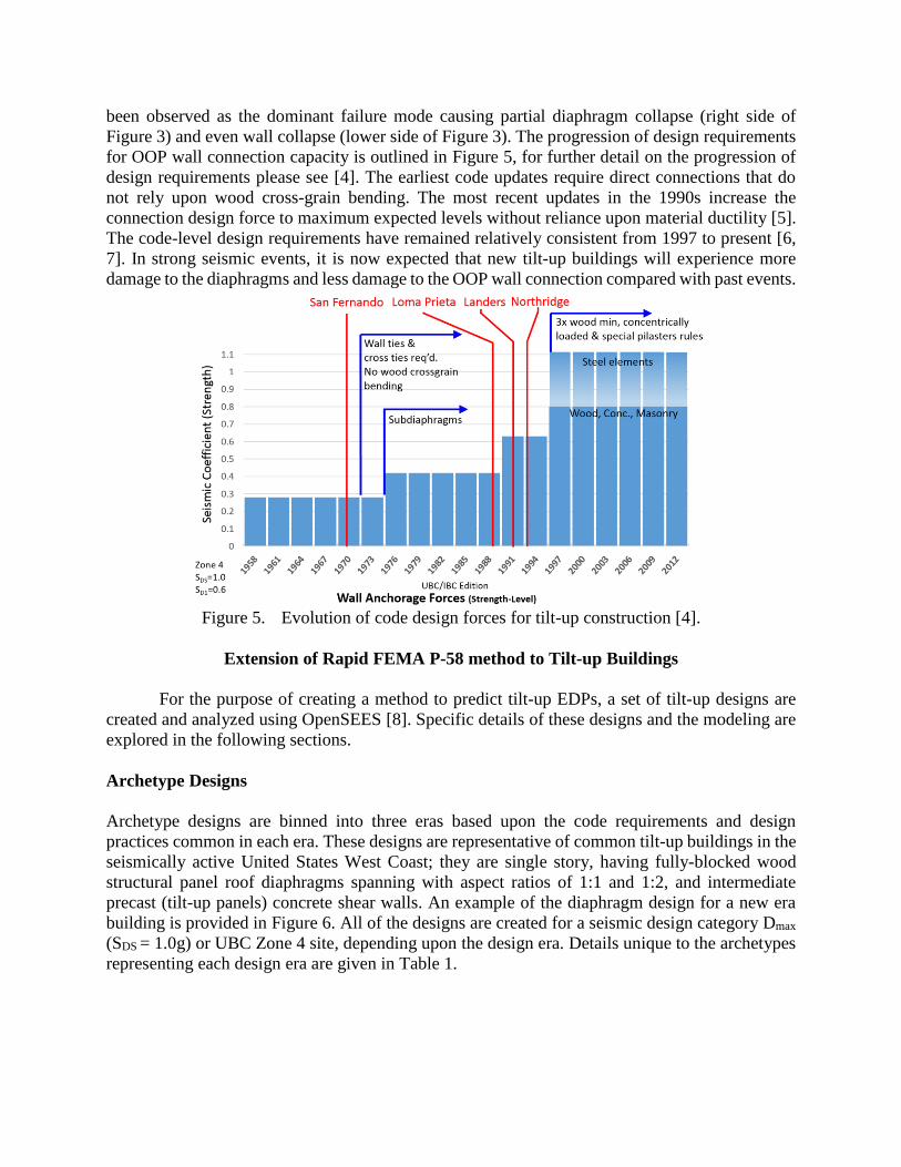
been observed as the dominant failure mode causing partial diaphragm collapse (right side of
Figure 3) and even wall collapse (lower side of Figure 3). The progression of design requirements
for OOP wall connection capacity is outlined in Figure 5, for further detail on the progression of
design requirements please see [4]. The earliest code updates require direct connections that do
not rely upon wood cross-grain bending. The most recent updates in the 1990s increase the
connection design force to maximum expected levels without reliance upon material ductility [5].
The code-level design requirements have remained relatively consistent from 1997 to present [6,
7]. In strong seismic events, it is now expected that new tilt-up buildings will experience more
damage to the diaphragms and less damage to the OOP wall connection compared with past events.
Figure 5. Evolution of code design forces for tilt-up construction [4].
Extension of Rapid FEMA P-58 method to Tilt-up Buildings
For the purpose of creating a method to predict tilt-up EDPs, a set of tilt-up designs are
created and analyzed using OpenSEES [8]. Specific details of these designs and the modeling are
explored in the following sections.
Archetype Designs
Archetype designs are binned into three eras based upon the code requirements and design
practices common in each era. These designs are representative of common tilt-up buildings in the
seismically active United States West Coast; they are single story, having fully-blocked wood
structural panel roof diaphragms spanning with aspect ratios of 1:1 and 1:2, and intermediate
precast (tilt-up panels) concrete shear walls. An example of the diaphragm design for a new era
building is provided in Figure 6. All of the designs are created for a seismic design category Dmax
(SDS = 1.0g) or UBC Zone 4 site, depending upon the design era. Details unique to the archetypes
representing each design era are given in Table 1.
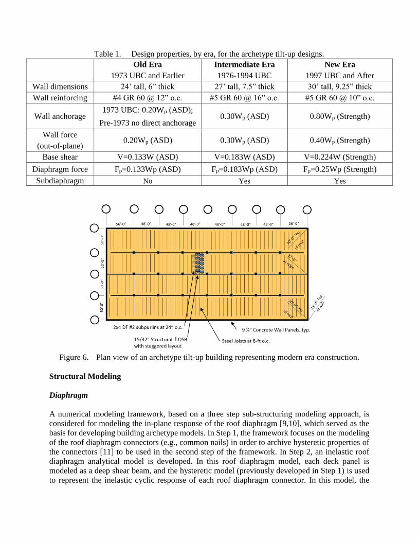
Table 1. Design properties, by era, for the archetype tilt-up designs.
Old Era Intermediate Era New Era
1973 UBC and Earlier 1976-1994 UBC 1997 UBC and After
Wall dimensions 24’ tall, 6” thick 27’ tall, 7.5” thick 30’ tall, 9.25” thick
Wall reinforcing #4 GR 60 @ 12” o.c. #5 GR 60 @ 16” o.c. #5 GR 60 @ 10” o.c.
Wall anchorage 1973 UBC: 0.20Wp (ASD);
0.30Wp (ASD) 0.80Wp (Strength) Pre-1973 no direct anchorage
Wall force 0.20Wp (ASD) 0.30Wp (ASD) 0.40Wp (Strength)
(out-of-plane)
Base shear V=0.133W (ASD) V=0.183W (ASD) V=0.224W (Strength)
Diaphragm force Fp=0.133Wp (ASD) Fp=0.183Wp (ASD) Fp=0.25Wp (Strength)
Subdiaphragm No Yes Yes
Figure 6. Plan view of an archetype tilt-up building representing modern era construction.
Structural Modeling
Diaphragm
A numerical modeling framework, based on a three step sub-structuring modeling approach, is
considered for modeling the in-plane response of the roof diaphragm [9,10], which served as the
basis for developing building archetype models. In Step 1, the framework focuses on the modeling
of the roof diaphragm connectors (e.g., common nails) in order to archive hysteretic properties of
the connectors [11] to be used in the second step of the framework. In Step 2, an inelastic roof
diaphragm analytical model is developed. In this roof diaphragm model, each deck panel is
modeled as a deep shear beam, and the hysteretic model (previously developed in Step 1) is used
to represent the inelastic cyclic response of each roof diaphragm connector. In this model, the

continuity ties are assumed adequate. The total in-plane flexible roof diaphragm displacement is
computed as the sum of: (i) the elastic shear deformation of each individual panel, (ii) the inelastic
deformations (slippage) of connectors and (iii) the elastic flexural deformations of the chord
members. In Step 3 of the numerical framework, a two-dimensional building model is generated
in the general-purpose RUAUMOKO2D [12] software, representing the three-dimensional
building without accounting for torsion. The vertical wall responses are considered in this model
and are addressed more completely in the next section. All three steps of this numerical framework
were validated with analytical and experimental studies available in the literature [9], while all
modeling parameters were identified through a set of sensitivity studies [10]. The RUAUMOKO
building model served as the basis for generating and calibrating OpenSEES models of the
building archetypes considered in this study.
Figure 7. Process for modeling the roof diaphragm [9].
Tilt-up Concrete walls
Tilt-up concrete walls are modeled as
linearly elastic for deformations in the
plane of the wall. Out-of-plane, the
walls are modeled with linear beam-
column elements connected by three
equally spaced trilinear plastic hinges
with pinched response. Plastic hinge
strengths are computed from expected
material properties, using a concrete
rupture modulus 𝑓𝑟 = 5√𝑓′𝑐 [13].
Rotation capacity is calibrated to
match the UBC deflection equations,
which align well with test data [14]—
moment amplification due to axial
loading of the walls is considered
when computing the UBC
displacements. Figure 8 shows a
comparison of the OpenSEES out-of-
plane wall moment-displacement
relationship and the target displacement curve for the new era archetypes. P-Δ effects are explicitly
included in the OpenSEES models.
Figure 8. Moment-deflection curve for the new era
out-of-plane walls, subjected to a uniformly
distributed out-of-plane wall force.
-1 -0.5 0 0.5 1-300
-200
-100
0
100
200
300
400
Displacement (inches)
Fo
rce(l
bs)
Test
-1 -0.5 0 0.5 1-300
-200
-100
0
100
200
300
Displacement (inches)
Fo
rce(l
bs)
SAWS model-estimated
-1 -0.5 0 0.5 1-300
-200
-100
0
100
200
300
Displacement (inches)
Fo
rce(l
bs)
Wyane-Stewart model-estimated
Connector Database Diaphragm model
V
4rx 3rx2rx 1rx
-1 -0.5 0 0.5 1-300
-200
-100
0
100
200
300
400
Displacement (inches)
Fo
rce(l
bs)
Test
-1 -0.5 0 0.5 1-300
-200
-100
0
100
200
300
Displacement (inches)
Fo
rce(l
bs)
SAWS model-estimated
-1 -0.5 0 0.5 1-300
-200
-100
0
100
200
300
Displacement (inches)
Fo
rce(l
bs)
Wyane-Stewart model-estimatedV
xr4 –xr3-1 -0.5 0 0.5 1
-300
-200
-100
0
100
200
300
400
Displacement (inches)
Fo
rce(l
bs)
Test
-1 -0.5 0 0.5 1-300
-200
-100
0
100
200
300
Displacement (inches)
Fo
rce(l
bs)
SAWS model-estimated
-1 -0.5 0 0.5 1-300
-200
-100
0
100
200
300
Displacement (inches)
Fo
rce(l
bs)
Wyane-Stewart model-estimated
V
xr3 –xr2-1 -0.5 0 0.5 1
-300
-200
-100
0
100
200
300
400
Displacement (inches)
Fo
rce(l
bs)
Test
-1 -0.5 0 0.5 1-300
-200
-100
0
100
200
300
Displacement (inches)
Fo
rce(l
bs)
SAWS model-estimated
-1 -0.5 0 0.5 1-300
-200
-100
0
100
200
300
Displacement (inches)
Fo
rce(l
bs)
Wyane-Stewart model-estimatedV
xr2 –xr1-1 -0.5 0 0.5 1
-300
-200
-100
0
100
200
300
400
Displacement (inches)
Fo
rce(l
bs)
Test
-1 -0.5 0 0.5 1-300
-200
-100
0
100
200
300
Displacement (inches)
Fo
rce(l
bs)
SAWS model-estimated
-1 -0.5 0 0.5 1-300
-200
-100
0
100
200
300
Displacement (inches)
Fo
rce(l
bs)
Wyane-Stewart model-estimatedV
xr1
Simplified Building Model
Xr4 Xr3 Xr1Xr2
V
V V V V
Xr4-Xr3 Xr3-Xr2 Xr2-Xr1 Xr1
md2
md3
xiwxd1
xd2xd3xd4
md1 miw
xd5
md5
0
5
10
15
20
25
30
-0.2
-0.1
0
0.1
0.2
0.3
Time[s
ec]
Acc
eler
atio
n [g
]
kd5kd4 kd3 kd2kd1
kiw
md4
Displacement
Force
Step 1 Step 2 Step 3

Structural Analysis: Engineering Demand Parameters (EDPs)
The archetype models are subjected to a series of incremental dynamic analyses with a suite of 44
far-field ground motion recordings from strong events [15], scaled to a broad range of intensity
levels. The following EDPs are tracked at intervals along the length of the OOP wall:
1. Diaphragm ductility demand (μ)—ratio of diaphragm deflection demand to the deflection
at which the diaphragm yields.
2. Out-of-plane wall connection force demand—force in the connection between the roof
diaphragm and OOP wall, measured in units of g.
3. Out-of-plane wall flexure demand—ratio of relative deflection at the mid height of the wall
to the wall span height, Δs/L (Figure 4).
4. Roof drift ratio—ratio of horizontal displacement at the roof to the roof height.
5. Residual roof drift ratio—ratio of residual horizontal displacement at the roof to the height
at the roof.
6. Peak roof acceleration—peak acceleration at the roof, measured in units of g.
Based on the suite of nonlinear response history analyses conducted for this study, a
statistical model was developed to make probabilistic predictions of the EDPs based on building
properties and ground shaking intensity at the fundamental period of each archetype, Sa(T1). The
flowchart in Figure 9 illustrates the process by which EDPs are obtained using this process. The
component strengths that are used to predict EDPs are expected strengths, i.e. the design strength
with an appropriate overstrength factor applied. Design strength is computed based on the building
code that was in effect when the building was designed and the seismic zone/category and site
class for the building. The elastic fundamental period of the building is computed using the
relationship developed by [16], which depends on properties of the rigid concrete (tilt-up) shear
walls and the flexible wood roof diaphragm. This is much different than the empirical equations
in ASCE/SEI 7, which are inaccurate for buildings whose primary response is in the roof
diaphragm [17, 18].
Figure 9. Flowchart describing the process by which EDPs are obtained for tilt-up buildings.

Tilt-up Component Fragilities
FEMA P-58 fragilities are families of cumulative
distribution functions representing the likelihood of
reaching or exceeding a set of damage states.
Figure 10 shows a fragility function for wood
diaphragms considered in this study. In total, 42
fragilities are created to represent damageable
structural components in tilt-up buildings across
the three archetype eras considered in this study.
Development of tilt-up fragilities is guided
by [7]; OOP connections are identified as the
primary cause of partial or complete collapse in
buildings designed before the 1994 Northridge
Earthquake. [7] goes on to identify other
damageable components in tilt-up buildings and
rates them in order of importance for retrofit, i.e.
identifying the components most likely to damage
and cause serious repercussions. The threshold for damage as well as the associated repair
consequences are estimated according to the FEMA P-58 method for each component using the
design code era and damage state specific repair schedules. Table 2 summarizes three fragility
types, specific to tilt-up buildings that are developed in this study.
Example Results
Tilt-up test buildings at several Southern California sites, having varying layouts and design eras,
are analyzed with the FEMA P-58 method using the Seismic Performance Prediction Program
(SP3, [19]). The FEMA P-58 approach gives site-specific, building specific, age specific results,
as evidenced by the vulnerability functions shown in Figure 11. For comparisons to existing
methods that give loss in an average sense (rather than building specific), results for HAZUS [21]
and ATC 13 [22] are also shown. The source of the losses computed with the FEMA P-58 method
may be further disaggregated to identify the components and associated EDPs that dominate total
loss. For example, in early era archetypes, failures of the OOP wall connection to the diaphragm
dominate loss. The loss sensitivity to EDPs across eras are examined qualitatively in Table 3.
Conclusion
Performance of tilt-up buildings is deeply dependent upon the code year for which the building is
designed and location of the building. This makes simplified assessment of seismic performance
for tilt-up buildings difficult. The FEMA P-58 method is distinctive in its capacity to
probabilistically examine the effect on seismic performance of building variables from site
conditions to building component detailing. This capacity of the FEMA P-58 method has been
unlocked for existing and new design tilt-up buildings by the creation of a probabilistic method
for structural response prediction and the creation of fragilities unique to these tilt-up structures.
Figure 10. Wood diaphragm fragility
functions.

Table 2. Tilt-up specific building component fragility summary.
Building
component EDP
Damage
state Description
Out-of-plane
connections OOP force
DS 1 Connection failure, partial diaphragm collapse.
DS 2 DS 1 + OOP wall collapse.
Precast tilt-up wall
out-of-plane
OOP wall
deflection
DS 1 Residual cracking.
DS 2 DS 1 + residual drift requiring re-alignment.
Wood diaphragm Diaphragm
ductility
DS 1 Roof material tearing at in-plane walls.
DS 2 DS 1 + nail pull-out, framing splitting, plywood/OSB
tearing.
DS 3 DS 2 + plywood/OSB panels pull free, framing splitting.
Figure 11. Vulnerability functions for tilt-up buildings: (a) 400’x400’ modern era design at various
locations, (b) Three different design eras at a site near San Bernardino.
Table 3. Summary of EDPs for calculating tilt-up building losses.
EDP Unique to
tilt-up bldgs?
Relative contribution to loss, by era
Early era Intermediate era New era
Diaphragm ductility demand YES* Low Moderate High
Out-of-plane wall connection
force demand YES* High High
Low/
Moderate
Out-of-plane wall deformation YES* Low Low Moderate
Roof drift ratio NO Low Low Low
Residual roof drift ratio NO Low Low Low
Peak roof acceleration NO Low Low Moderate
* EDPs categorized as “unique” to tilt-up buildings also occur in other building types, but their
contribution to damage in other buildings is often of little significance.
(a) (b)

Acknowledgements
The study is partially funded by the National Science Foundation (NSF) through a Small Business
Innovation Research Grant (#1632429). Any opinions contained in this article represent those of
the authors and do not necessarily represent the opinions of NSF.
References 1. FEMA (2012). FEMA-P-58: Seismic Performance Assessment of Buildings Volume 1 – Methodology. Prepared
by ATC for FEMA.
2. Moehle J, Deierlein G. (2004)A Framework Methodology for Performance-Based Earthquake Engineering. 13th
World Conference on Earthquake Engineering, Vancouver, Canada.
3. ICBO (1997). 1997 Uniform Building Code. International Conference of Building Officials: Whittier, CA.
4. Koliou M, Lawson J, Filiatrault A, and Kelly, D.J. (2017). Evaluation of Out-of-Plane Wall Anchorage Force
Provisions in Buildings with Rigid Walls and Flexible Roof Diaphragms, Earthquake Spectra, 33(1), pg. 1-23.
5. SEA (1999). Recommended Lateral Force Requirements and Commentary. Structural Engineers Association of
California: Albany, CA.
6. Lawson J, Kelly D, Koliou M, Filiatrault A. (2014) Evaluating Existing and Proposing New Seismic Design
Provisions for Rigid Wall – Flexible Diaphragm Buildings. SEAOC Annual Convention Proceedings 2014.
7. SEAONC (2001). Guidelines for Seismic Evaluation and Rehabilitation of Tilt-up Buildings and Other Rigid
Wall/Flexible Diaphragm Structures. Structural Engineers Association of Northern California: San Francisco,
CA, 2001.
8. PEER (2016). OpenSEES (Open System for Earthquake Engineering Simulation). opensees.berkeley.edu.
9. Koliou M, Filiatrault A, Kelly D.J., and Lawson J. (2016a), Distributed Yielding Concept for Improved Seismic
Collapse Performance of Rigid Wall-Flexible Diaphragm Buildings, ASCE Journal of Structural Engineering,
142(2).
10. Koliou M, Filiatrault A, Kelly D.J., and Lawson J. (2014), Two-Dimensional Numerical Framework for
Seismic Collapse Assessment of Rigid Wall – Flexible Diaphragm Structures, 10th US National Conference on
Earthquake Engineering, Anchorage Alaska, July 2014.
11. Koliou M, Filiatrault A. (2017), Development of Wood and Steel Diaphragm Hysteretic Connector Database for
Performance-Based Earthquake Engineering. Bulletin of Earthquake Engineering.
12. Carr A.J. (2007). RUAUMOKO2D. University of Canterbury.
13. Lawson J, Lai J. (2010). Concrete Slender Wall Design – Back to the Future. SEAOC 2010 Convention
Proceedings.
14. ACI-SEAOSC. (1982). Test Report on Slender Walls. By the ACI-SEAOSC Task Committee on Slender Walls,
Structural Engineers Association of Southern California, Whittier, CA.
15. FEMA (2009). FEMA P695: Quantification of Building Seismic Performance Factors. Prepared by ATC for
FEMA.
16. Koliou M, Filiatrault A, Kelly D.J. and Lawson J. (2016b), Buildings with Rigid Walls and Flexible Roof
Diaphragms I: Evaluation of Current United States Seismic Provisions, ASCE Journal of Structural
Engineering, 142(3).
17. Lawson J, Kelly D.J., Koliou M, Filiatrault A. (2014), An Alternative Procedure for the Seismic Design of
Buildings with Rigid Walls/Flexible Diaphragms: FEMA P-1026, 16th World Conference on Earthquake
Engineering, Santiago, Chile, January 2017.
18. 2. FEMA P-1026 (2015). Seismic Design of Rigid Wall-Flexible Diaphragm Buildings: An Alternative
Procedure. March, 2015.
19. Haselton Baker Risk Group (2017). SP3 (Seismic Performance Prediction Program). hbrisk.com.
20. FEMA (2015). Seismic Design of Rigid Wall-Flexible Diaphragm Buildings: An Alternate Procedure. National
Institute of Building Sciences: Washington DC, 2015.
21. FEMA. HAZUS Earthquake Module. Federal Emergency Management Agency: Washington DC.
22. ATC (1985). ATC-13: Earthquake Damage Evaluation Data for California. Applied Technology Council
(ATC): Redwood City, CA.