seaoc blue book – seismic design recommendations tilt-up
TRANSCRIPT
SEAOC Blue Book – Seismic Design RecommendationsTilt-up Buildings
ASCE 7-05reference section(s)
ACI 318-05Reference section(s)
2006 IBCreference section(s)
12.11 14.821.721.821.13
1908.1.161908.1.81908.1.132305
IntroductionThe reinforced concrete tilt-up building is the most popular form of light industrial and low-rise commercialconstruction in the Western United States and is a significant portion of new construction nationwide. Thispopularity is primarily driven by the construction speed and economical nature of tilt-up construction. Architecturalacceptance has become more widespread as tilt-up construction has adapted to the demands of taller buildings withbetter aesthetics involving irregular plan shapes, more glass, and accent treatments. Tilt-up construction is becomingmore common for office buildings, assembly occupancies, and even schools. Originally a one-story form ofconstruction, tilt-up buildings are now commonly two and three stories.
Unfortunately, the uniqueness and rapid evolution of tilt-up construction have made it a challenge for seismicprovisions in building codes to keep pace. Poor performance in past earthquakes has been responsible for significantrevisions to building codes and in some jurisdictions mandated seismic retrofit requirements of older tilt-upbuildings. This article describes unique problems associated with tilt-up seismic design, how the past has shapedcurrent recommended practice, and insights from recent research on tilt-up building behavior.
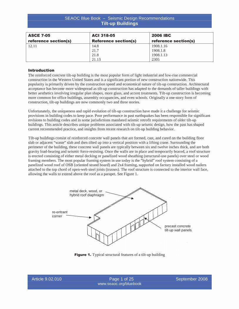
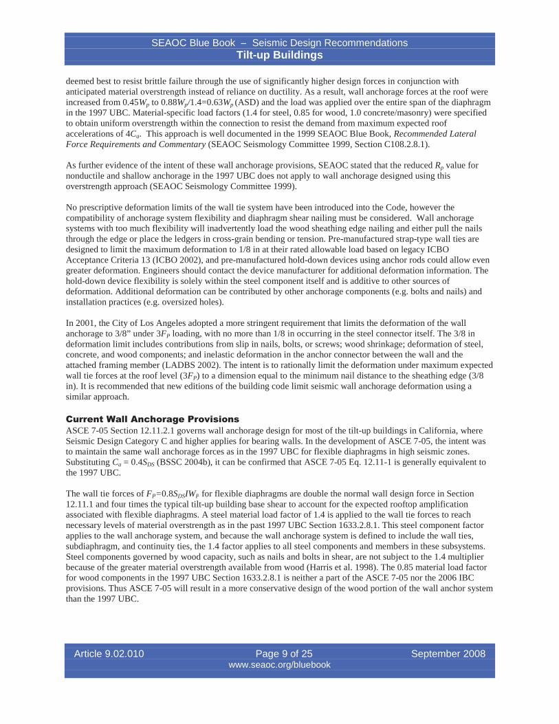
Tilt-up buildings consist of reinforced concrete wall panels that are formed, cast, and cured on the building floorslab or adjacent “waste” slab and then tilted up into a vertical position with a lifting crane. Surrounding theperimeter of the building, these concrete wall panels are typically between six and twelve inches thick, and are bothgravity load-bearing and seismic force-resisting. Once the walls are in place and temporarily braced, a roof structureis erected consisting of either metal decking or panelized wood sheathing (structural-use panels) over steel or woodframing members. The most popular framing system in use today is the “hybrid” roof system consisting of apanelized wood roof of OSB (oriented strand board) and 2x4 framing, supported on factory installed wood nailersattached to the top chord of open-web steel joists (trusses). The roof structure is connected to the interior wall face,allowing the walls to extend above the roof as a parapet. See Figure 1.
metal deck, wood, orhybrid roof diaphragm
re-entrantcorner
precast concretetilt-up wall panels
Figure 1. Typical structural features of a tilt-up building
Article 9.02.010 Page 1 of 25 September 2008www.seaoc.org/bluebook
SEAOC Blue Book – Seismic Design RecommendationsTilt-up Buildings
The most critical component of tilt-up building seismic performance is the anchorage of the wall to the roofstructure. This anchorage is accomplished with embedded concrete anchors or straps attached to the roof framingsystem. Finally, the wall panels are connected to the slab-on-grade through lapped reinforcing within a pour strip orfill-in strip of concrete floor. It is also strongly recommended that the wall panels be connected to the foundations inhigh seismic zones to provide a positive load path.
Historical BackgroundMany seismic code provisions that have evolved over the years envision either classic frame structures with rigiddiaphragms or light frame buildings with small lightweight diaphragms. Tilt-up construction is unique with its manydifferent material combinations and has unique performance issues that have not generally entered the code untilevidence of a problem from a failure. Tilt-up construction has experienced many earthquake-induced failures in thepast (EERI 1988, SEAONC 2001). The tilt-up provisions that do exist are scattered throughout the code, primarilybecause tilt-up does not fit neatly into one material type. IBC Chapter 16 (Structural Design), Chapter 19 (Concrete),Chapter 22 (Steel), and Chapter 23 (Wood) all contain important provisions for the design of the various materialsassociated with diaphragms, collectors, and wall anchorage, and with the main lateral force-resisting system.
Even though the code has become more prescriptive, there are many aspects of design that vary significantlybetween engineers. There still is no clear direction provided on some important engineering issues such as thefollowing:
x How to properly tie into a re-entrant wall;x How shear loads are distributed along a line of perforated shear walls;x Whether wall ties should be designed for compression or tension only.
Walls Loaded Out-of-Plane. Prior to the development of slender wall code provisions in the 1980s, concretewalls were limited to arbitrary height/thickness (h/t) ratios creating walls much thicker than typically seen today. Itwas believed that very slender walls could buckle prematurely or deflect so much as to not be serviceable afterearthquakes.
To justify thinner walls, panels were joined together with cast-in-place pilaster stiffeners formed between adjacentpanels. The concrete wall panels spanned horizontally out-of-plane between the pilasters, and the pilasters spannedvertically between the floor slab and a supporting roof beam. Horizontal concrete panel reinforcing extended into thecast-in-place joint, effectively making all the panels behave monolithically.
In the 1970s, engineers began experimenting with wall panel designs spanning vertically between the floor slab androof, leaving the panel joints dry and caulked with waterproof sealants. Pilasters cast with the panels were stillprovided (usually on just one panel edge), but only for the purpose of providing roof beam gravity load reactions.The panels were now themselves spanning vertically without the reliance on the pilasters, behaving as tall, slenderwalls. ACI 318 limited bearing wall slenderness to a height-to-thickness (h/t) ratio of 25, and these tall, slender wallsdid not conform to the typical UBC or ACI code provisions for concrete walls. The slenderness restriction preventedeconomical use of vertically spanning tilt-up panels.
Instead, engineers began experimenting with new analysis techniques to include second order effects, or P' moments, as a means to circumvent the arbitrary h/t limits prescribed by ACI. Inadvertently, many engineers used amoment magnification method in ACI 318-71 to account for these second order effects, but this method was notdeveloped for flexural members with only a central layer of steel. Another approach used was to conduct rigorousstrain compatibility reviews or to use published papers such as the 1974 report, Tilt-Up Load-Bearing Walls—ADesign Aid, by the Portland Cement Association (Kripanarayanan 1984). Even though very thin wall panels werebeing erected successfully in the 1970s, there was growing concern over the engineering fundamentals behind theanalysis of these walls.
In response to the explosive growth of tilt-up construction that was based on potentially misapplied code provisions,the Structural Engineers Association of Southern California (SEAOSC) published in 1979 their Recommended Tilt-
Article 9.02.010 Page 2 of 25 September 2008www.seaoc.org/bluebook
SEAOC Blue Book – Seismic Design RecommendationsTilt-up Buildings
Up Wall Design, also known as the “Yellow Book” (SEAOSC 1979), and was quickly followed in 1982 by the“Green Book” titled Test Report on Slender Walls (ACI-SEAOSC 1982). Based on the work of SEAOSC and theSouthern California Chapter of ACI, this important publication contained the results of thirty full-scale tests ofslender walls under out-of-plane loading (twelve slender concrete walls with the others being masonry), and itconfirmed the recommended design provisions of the “Yellow Book” but without arbitrary height-to-thickness (h/t)limits.
These provisions recognized that with light axial loads, tilt-up wall panels behave more like flexural members thancompression wall sections, thus eliminating the need for arbitrary height-to-thickness limits. Both P-delta effectsand eccentric loading were deemed very important considerations, because slender panels are capable of undergoinglarge out-of-plane deflections, and the provisions provided equations that estimated the non-linear deflectioncharacteristics out-of-plane. Also, the flexural reinforcement ratio and axial loading were restricted to ensure ductileflexural yielding while mitigating sudden buckling collapse. One of the inherent advantages of using what becameknown as slender wall design is the reasonably thinner wall panels, which in turn reduce the seismic force at the roofdiaphragm. Even though the SEAOSC provisions were not incorporated into the UBC until 1988, engineers werequick to embrace these guidelines in their designs.
The very large deflections observed in the testing program raised serviceability concerns with theSEAOSC/SCCACI task committee. Slender walls designed to strength requirements alone, free of h/t ratios, couldbe overly flexible, possibly resulting in permanent deformation. On several of the full-scale test specimens, reboundstudies were conducted and it was found that some permanent deformation was possible in wall panels prior toreaching theoretical yield. Quoting the Green Book, “The tests demonstrated that there was no validity for fixedheight-to-thickness limits, but they did reveal the need for deflection limits to control potential residual deflection inpanels after service loads experience.” Based on their limited rebound study and much discussion, theSEAOSC/SCCACI task committee recommended an L/100 deflection limit.
The recommended provisions of the Yellow Book and Green Book were the basis of the first building coderequirements in the 1988 UBC. The one important difference between the Green Book and the UBC was thedeflection limit at service loads was more restrictively set at L/150. This was set by consensus opinion during the1984-1986 UBC code development process, but it is not clear what rational basis there was behind the revision.
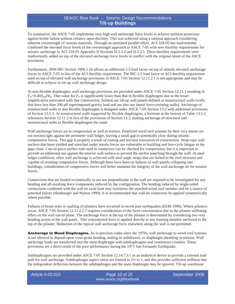
Another important aspect of both the Green Book and UBC equations was defining the concrete cracking moment,
Mcr , based on the modulus of rupture, f 5 f c , of concrete. This is two-thirds of the traditional ACI equationr c
f 7.5 f c , but it matched the full-scale test data far better. By uniquely defining Mcr and applying a bilinearr c
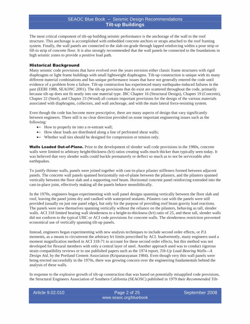
curve equation, the UBC load-deflection curve matched well with the test results. See Figure 2. These equationscontinued to be incorporated up through the 1997 UBC.
Historically, the out-of-plane seismic performance of slender tilt-up wall panels has been relatively good, withfailures of a panel itself very rare. Often the worst out-of-plane loading occurs during crane lifting in theconstruction process. In the 1987 Whittier Narrows, California earthquake, some out-of-plane damage was observedat the sides of large wall openings, but the damage was associated with post-construction saw cut openings installedwithout strengthening or engineering (EERI 1988).
Today, out-of-plane tilt-up wall panel design is incorporated into ACI 318-05 Section 14.8, and is still largely basedon the original SEAOSC testing and recommendations.
The lateral force coefficient for out-of-plane structural wall forces for Seismic Design Category B and above isprovided in ASCE 7-05 Section 12.11.1 as FP=0.40SDSIWw. Using the lateral force coefficient to determine the out-of-plane wall forces, an engineer normally selects vertical design strips to determine moment and reinforcingrequirements. At wall piers between wall openings and panel joints, the design strip usually is the entire pier width,with loads accounting for the increased seismic tributary loading associated with the panel portions above and below
Article 9.02.010 Page 3 of 25 September 2008www.seaoc.org/bluebook
SEAOC Blue Book – Seismic Design RecommendationsTilt-up Buildings
Figure 2. Moment-Deflection Curves Comparing Test Data with UBCPanel #25 SCCACI-SEAOSC March 20, 1981; 6-in-thick reinforced slender wall
the openings. This approach typically neglects any additional strength or stiffness provided by the portions of thewall above and below the openings, using a simple strip of uniform width as an analytical tool.
Cantilever parapets that are part of a continuous wall element are checked separately for higher seismic forces perASCE 7-05 Section 13.3.1. Unlike the structural wall panels, the parapet forces are based on nonstructuralcomponent equations. It is not appropriate to use the higher cantilever parapet forces to offset the wall positivebending moment below the roof.
Whereas the UBC equations checking strength remained essentially in concert with the ACI 318 adoption, theservice level deflection equations were significantly altered. The most significant difference was use of Branson’sequation for the effective moment of inertia, Ie, in ACI in place of the UBC bilinear load-deflection equation. Inaddition, the value for Mcr within Branson’s equation was set at the traditional ACI value.
3 3ª º¨§¨ ¨
§¨
M M· ·I I «
«¬1 I d I� �cr cr »
»¼¸ ¸¹
¸ ¸¹
e g cr gM M© ©a a
Where,
�cf 'M Sf Scr r
Article 9.02.010 Page 4 of 25 September 2008www.seaoc.org/bluebook
� 5.7
L /150
300 ---", """"""~_~_"J' ""'J'J'J'~~N__"_~'--'~""'__~__"""J"J'J'_J'J'J' "",""",""'J'oI'~""""''''''''''''''J''''---'~~-l
250 -l-----+-----------------------=__.....~=--------~
Mn_
_ 200 +-----+--------------::::;~~~~-----------------_______jtilQ.:iC=- 150 +----~~--~~-------------------------_______jcQ)
Eo:E 100 -+-I----~---+----------------------------------_______1
50 -U------f-----------------------------~
121086
Deflection (in)
42
o-L----.--.--.......--!...,..-..,........-,----,---r---r--,............-,---,.-..,...--,----,-..,.......----,--r---r-----r-,---,.----,-..,................,...---j
o
SEAOC Blue Book – Seismic Design RecommendationsTilt-up Buildings
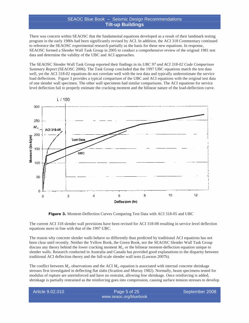
There was concern within SEAOSC that the fundamental equations developed as a result of their landmark testingprogram in the early 1980s had been significantly revised by ACI. In addition, the ACI 318 Commentary continuedto reference the SEAOSC experimental research partially as the basis for these new equations. In response,SEAOSC formed a Slender Wall Task Group in 2005 to conduct a comprehensive review of the original 1981 testdata and determine the validity of the UBC and ACI approaches.
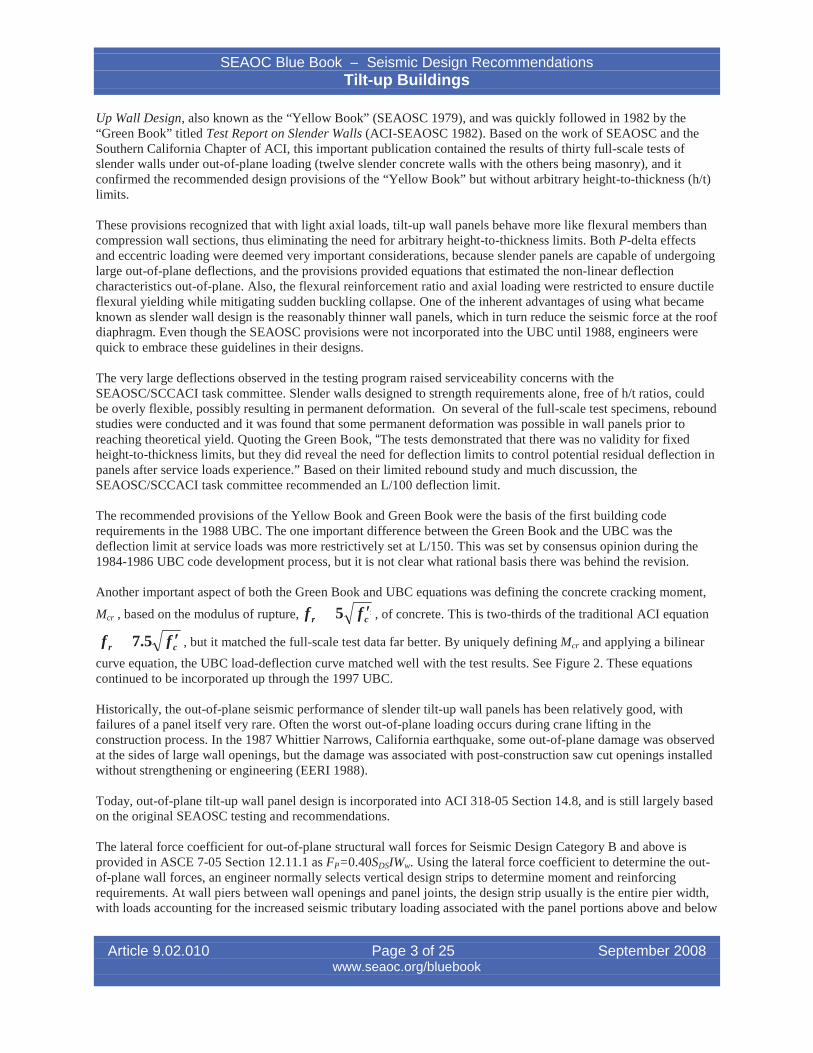
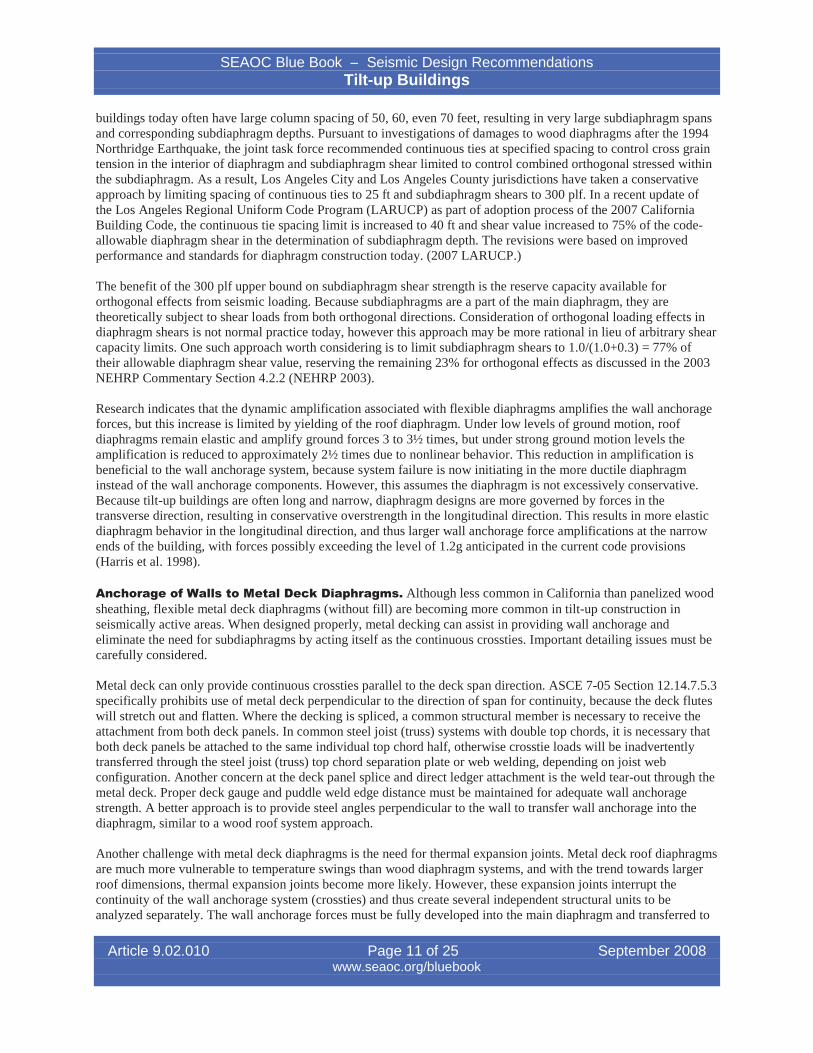
The SEAOSC Slender Wall Task Group reported their findings in its UBC 97 and ACI 318-02 Code ComparisonSummary Report (SEAOSC 2006). The Task Group concluded that the 1997 UBC equations match the test datawell, yet the ACI 318-02 equations do not correlate well with the test data and typically underestimate the serviceload deflections. Figure 3 provides a typical comparison of the UBC and ACI equations with the original test dataof one slender wall specimen. The other wall specimens had similar comparisons. The ACI equations for servicelevel deflection fail to properly estimate the cracking moment and the bilinear nature of the load-deflection curve.
Figure 3. Moment-Deflection Curves Comparing Test Data with ACI 318-05 and UBC
The current ACI 318 slender wall provisions have been revised for ACI 318-08 resulting in service level deflectionequations more in line with that of the 1997 UBC.
The reason why concrete slender walls behave so differently than predicted by traditional ACI equations has notbeen clear until recently. Neither the Yellow Book, the Green Book, nor the SEAOSC Slender Wall Task Groupdiscuss any theory behind the lower cracking moment Mcr or the bilinear moment-deflection equation unique toslender walls. Research conducted in Australia and Canada has provided good explanations to the disparity betweentraditional ACI deflection theory and the full-scale slender wall tests (Lawson 2007b).
The conflict between Mcr observations and the ACI Mcr equation is associated with internal concrete shrinkagestresses first investigated in deflecting flat slabs (Scanlon and Murray 1982). Normally, beam specimens tested formodulus of rupture are unreinforced and have no restraint, allowing free shrinkage. Once reinforcing is added,shrinkage is partially restrained as the reinforcing goes into compression, causing surface tension stresses to develop
Article 9.02.010 Page 5 of 25 September 2008www.seaoc.org/bluebook
L / 150~ .,.,,,,JVJVVV"'_..,.,,.,..,,,.,,.~ ,,,,,,~,...,.,.,,,........,_,......,.,.,,,,._.,..,..,.,,.._..;;_,.,,,.J'W'...,,,....,,~~~_"""""~"""""' ..... ........................_""""_:
~
250 +---.--+-----------------------=;.-,..,.~::::::..------~
_ 200 +-------,#':.---I-----------"..",.=-~~-----------------------<oC.:i!C::::.. 150 +---+---~~---...~-------------------------____1CCI)
Eo~ 100 -l-IJ~~---+-----------------------------------____1
50 -U------+-----------------------------------(
121086
Deflection (in)
42
O~..........,....-,.............,...._..!.....,..-_r___.____,_-_.___.........,..-.__...,......__r-.,.___r____r-..,.__,.-.._...,......----.-..,................,.....___r-,_--r----i
o
SEAOC Blue Book – Seismic Design RecommendationsTilt-up Buildings
in the concrete. These pre-existing tension stresses cause reinforced members to crack earlier than expected in plainconcrete. Flexural members with low reinforcement ratios such as tilt-up slender walls are especially sensitive toshrinkage restraint stress, thus significantly reducing the effective cracking moment (Scanlon and Bischoff 2007,Gilbert 2001).
The stiffness of members with only a central layer of reinforcing or that are lightly reinforced depends greatly on thetensioning effects of the plain concrete near the surface. Once this concrete cracks, there is usually an abrupt changein stiffness. Without consideration of the shrinkage effects, stiffness can be significantly underestimated and thusunexpected deflections can occur under service level loads. Other building codes around the world already havesimilar provisions for a reduced effective cracking moment or modulus of rupture due to shrinkage restraint,including the Australian Standard for Concrete Structures AS3600, the Canadian Code CSA A23.3 (for slabs), andthe Eurocode. A comparison of these codes in conjunction with available testing data indicates that use of 0.67Mcror use of f r 5 f cc in typical slender wall design is appropriate instead of the current ACI 318 (Scanlon andBischoff 2007, Lawson 2007b).
The reduced effective cracking moment outlined above does not fully explain the better fit of the bilinear curve usedby the UBC. Bischoff and Scanlon (2007) studied this issue with respect to concrete reinforced with FiberReinforced Polymer Bars and found similar issues persist among other thin lightly reinforced concrete members,including concrete tilt-up wall panels
Bischoff identified significant limitations with Branson’s equation for Ie when applied to thin concrete memberswith a central layer of steel, and he has proposed a solution. Branson’s Equation, first published in 1963, was basedon larger test beams where the ratio of gross/cracked moment of inertia (Ig/Icr) was typically 2.2. Bischoff found thatBranson’s equation became a poor predictor of deflection when this ratio exceeded three (Ig/Icr > 3). Slenderconcrete walls are far above this, with common values ranging from 15 to 25 for single layer reinforced walls and 6to 12 for double-layer reinforced walls. Thus deflection is under predicted.
Bischoff has proposed a new equation as a replacement to Branson’s for effective moment of inertia. This equationmatches well with both larger flexural beams and thin slender walls, effectively transitioning seamlessly to a nearbilinear load-deflection curve at high Ig/Icr ratios.
Icr II d I cre 2 g K 1�where1�K¨ ¸
§ Mcr · Ig¨ ¸M© a ¹
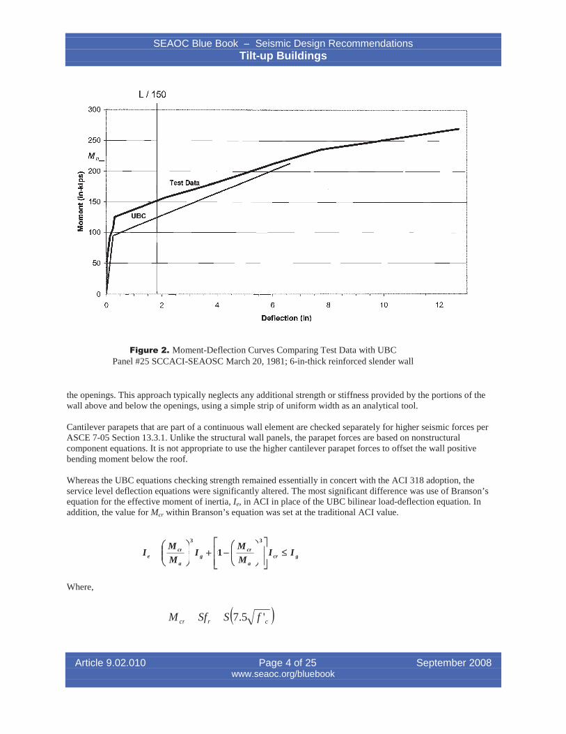
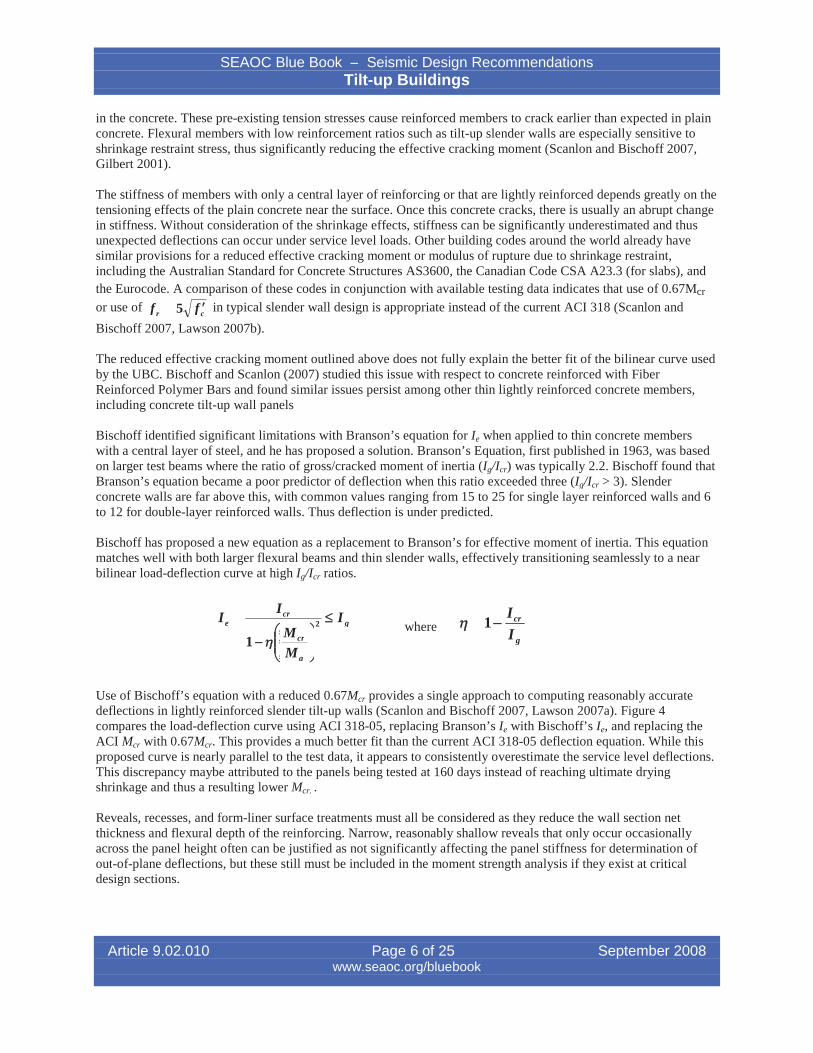
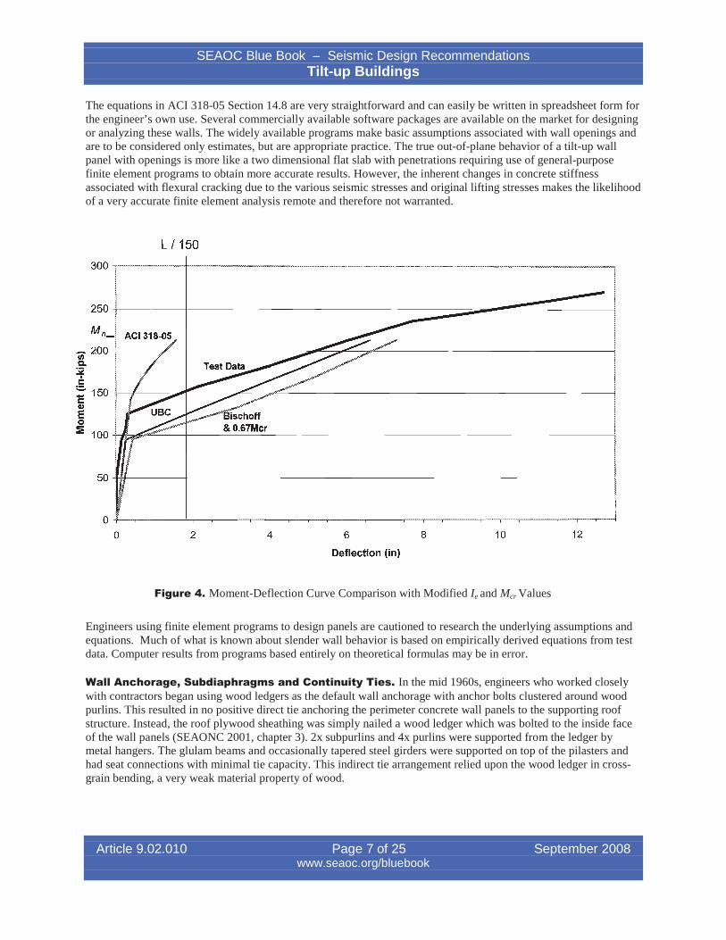
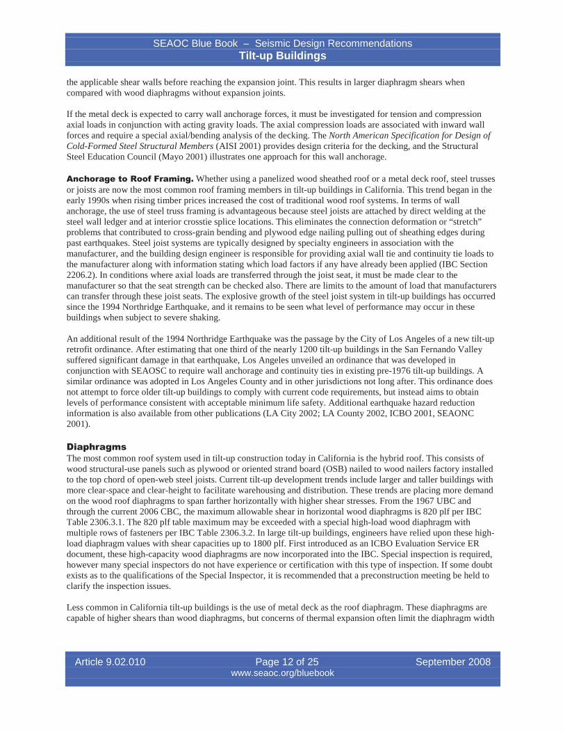
Use of Bischoff’s equation with a reduced 0.67Mcr provides a single approach to computing reasonably accuratedeflections in lightly reinforced slender tilt-up walls (Scanlon and Bischoff 2007, Lawson 2007a). Figure 4compares the load-deflection curve using ACI 318-05, replacing Branson’s Ie with Bischoff’s Ie, and replacing theACI Mcr with 0.67Mcr. This provides a much better fit than the current ACI 318-05 deflection equation. While thisproposed curve is nearly parallel to the test data, it appears to consistently overestimate the service level deflections.This discrepancy maybe attributed to the panels being tested at 160 days instead of reaching ultimate dryingshrinkage and thus a resulting lower Mcr. .
Reveals, recesses, and form-liner surface treatments must all be considered as they reduce the wall section netthickness and flexural depth of the reinforcing. Narrow, reasonably shallow reveals that only occur occasionallyacross the panel height often can be justified as not significantly affecting the panel stiffness for determination ofout-of-plane deflections, but these still must be included in the moment strength analysis if they exist at criticaldesign sections.
Article 9.02.010 Page 6 of 25 September 2008www.seaoc.org/bluebook
SEAOC Blue Book – Seismic Design RecommendationsTilt-up Buildings
The equations in ACI 318-05 Section 14.8 are very straightforward and can easily be written in spreadsheet form forthe engineer’s own use. Several commercially available software packages are available on the market for designingor analyzing these walls. The widely available programs make basic assumptions associated with wall openings andare to be considered only estimates, but are appropriate practice. The true out-of-plane behavior of a tilt-up wallpanel with openings is more like a two dimensional flat slab with penetrations requiring use of general-purposefinite element programs to obtain more accurate results. However, the inherent changes in concrete stiffnessassociated with flexural cracking due to the various seismic stresses and original lifting stresses makes the likelihoodof a very accurate finite element analysis remote and therefore not warranted.
Figure 4. Moment-Deflection Curve Comparison with Modified Ie and Mcr Values
Engineers using finite element programs to design panels are cautioned to research the underlying assumptions andequations. Much of what is known about slender wall behavior is based on empirically derived equations from testdata. Computer results from programs based entirely on theoretical formulas may be in error.
Wall Anchorage, Subdiaphragms and Continuity Ties. In the mid 1960s, engineers who worked closelywith contractors began using wood ledgers as the default wall anchorage with anchor bolts clustered around woodpurlins. This resulted in no positive direct tie anchoring the perimeter concrete wall panels to the supporting roofstructure. Instead, the roof plywood sheathing was simply nailed a wood ledger which was bolted to the inside faceof the wall panels (SEAONC 2001, chapter 3). 2x subpurlins and 4x purlins were supported from the ledger bymetal hangers. The glulam beams and occasionally tapered steel girders were supported on top of the pilasters andhad seat connections with minimal tie capacity. This indirect tie arrangement relied upon the wood ledger in crossgrain bending, a very weak material property of wood.
Article 9.02.010 Page 7 of 25 September 2008www.seaoc.org/bluebook
L /150
300
250
~_""""""""''''''''''''''''''.?o'"..,,,,, ,, ~.,.".".-_.,.".,.,.".".-""'>IVJV'~~ ~JV' ~="JV'~.....,....,o"V'..JV' -.r.rJV'JV'""" ...., ..,.."......,....,.,...,..._."....JV"J'.,.--~'--_ , .....",. J'.."...."..~ ~--l
IM~ I
_ 200 +--------#"-----+---------~....,:::::...__~_____,;;;;..-.=-------------------__jtnC.:s2C::- 150 +----f---~~--__::;o~-~"""'-------------------------__jcCDEo:li: 100 +-#l~>iP""'--+------------------------------______1
50 -f-H'-------+-------------------------------------i
121086
Deflection (in)
42
O-f-.......,...-.,.............,......l......r-...,................,..-..,..............,-......---.-----.-....,......-.--,....-.......,.,-,-...,................,..-.,......--,-r----.----,-,--.-----\
o
SEAOC Blue Book – Seismic Design RecommendationsTilt-up Buildings
In the 1971 San Fernando Earthquake, tilt-up buildings performed poorly. Many wood ledgers split length-wise dueto cross-grain bending loads, and plywood edge nailing pulled through plywood panel edges as the result of wallanchorage tension loads. Partial roof collapses and wall collapses were common in the areas of strong groundmotion (NOAA 1971, SEAONC, 2001). It was clear more restrictive code requirements would be needed.
Beginning with the 1973 UBC, the requirement for positive direct wall ties was introduced and wall anchorage usingwood cross-grain bending was expressly prohibited. In addition, continuous crossties were introduced for concreteand masonry walls supported by roof systems. In order to transfer seismic forces from the heavy perimeter walls intothe main roof diaphragm, continuous ties or crossties are necessary to drag the load uniformly across the diaphragmdepth.
In the 1976, UBC, the concept of subdiaphragms was introduced as an analytical device for transferring forces fromthe individual wall ties to the continuous crossties (Sheedy and Sheedy, 1992). Instead of creating a continuous tie atevery wall anchorage location, continuous crossties can be placed at wider spacing using subdiaphragms.Subdiaphragms are portions of the main diaphragm that span between the continuous crossties and gather the wallanchorage loads and transfer this load to the crossties. Once the load is collected into the continuous crossties it isdistributed across the main diaphragm for further distribution to shear walls and frames of the building.
In the 1979 UBC, the wall anchorage design force was increased 50% from 0.2Wp to 0.3Wp (where Wp is thetributary wall weight) for seismic zone 4. The code improvements of the 1970s were not tested until the 1984Morgan Hill, California Earthquake. Even though only a few tilt-up buildings saw moderate levels of shaking, itprovided the first performance comparison of tilt-up buildings built before and after the 1973 and 1976 codechanges. Several 1960s era tilt-up buildings suffered wall anchorage or continuity tie failures. On the other hand, atilt-up building built to more modern codes saw no structural damage despite the estimated 0.3g-0.4g groundaccelerations (EERI 1985).
The Whittier Narrows Earthquake in 1987 tested significantly more tilt-up buildings than the Morgan HillEarthquake, but forces were still only moderate. Pre-1973 UBC buildings saw failures at the wall in ledger crossgrain bending, cross-grain tension splits at interior diaphragm areas, and diaphragm nailing pulling through theplywood edges, similar to what was observed in the San Fernando Earthquake. In contrast, the tilt-up buildingsdesigned under more modern codes performed much better. Despite the better performance of the more moderncodes, there was some concern whether the code provisions were adequate to meet performance objectives undervery strong levels of shaking (EERI 1988).
Research on instrumented rigid wall buildings with flexible diaphragms following the 1984 Morgan Hill (Çelebi etal. 1989) and the 1989 Loma Prieta Earthquakes (Bouwkamp, Hamburger, and Gillengerten 1991) indicated that thedynamic response of structures with predominantly solid walls is dominated by the diaphragms, amplifying roofaccelerations and corresponding wall anchorage significantly more than previously thought. The recordedamplification of ground accelerations to roof accelerations resulted in the basis of a 1991 UBC revision increasingwall tie forces another 50% to 0.45Wp for seismic zone 4 (Sheedy and Sheedy 1992). This higher wall tie force wasonly required at the center half of the diaphragm span.
The 1994 Northridge, California Earthquake was the first test of modern post-1979 building code tilt-up provisionsunder very strong shaking. Hundreds of tilt-up buildings were severely damaged with partial roof collapses (CSSC1995, Brooks 2000). Damage in pre-1973 buildings was not necessarily a surprise, but the numerous wall anchoragefailures in post-1973 code buildings were troubling.
The unexpected wall anchorage damage to newer buildings was primarily attributed to two main reasons: inadequateconnection overstrength for the roof accelerations and excessive deformation of the wall anchor system (APA 1994,EERI 1996). Light-gauge steel twist straps were especially a problem due to their geometry and limited overstrength(Harris et al. 1998). Research and post-earthquake investigations have shown that rooftop accelerations may be threeto four times the ground acceleration, and insufficient overstrength or ductility has been provided in past connectionpractices (Çelebi et al. 1989, Harris et al. 1998). Based on observations of Northridge Earthquake damage, it was
Article 9.02.010 Page 8 of 25 September 2008www.seaoc.org/bluebook
SEAOC Blue Book – Seismic Design RecommendationsTilt-up Buildings
deemed best to resist brittle failure through the use of significantly higher design forces in conjunction withanticipated material overstrength instead of reliance on ductility. As a result, wall anchorage forces at the roof wereincreased from 0.45Wp to 0.88Wp/1.4=0.63Wp (ASD) and the load was applied over the entire span of the diaphragmin the 1997 UBC. Material-specific load factors (1.4 for steel, 0.85 for wood, 1.0 concrete/masonry) were specifiedto obtain uniform overstrength within the connection to resist the demand from maximum expected roofaccelerations of 4Ca. This approach is well documented in the 1999 SEAOC Blue Book, Recommended LateralForce Requirements and Commentary (SEAOC Seismology Committee 1999, Section C108.2.8.1).
As further evidence of the intent of these wall anchorage provisions, SEAOC stated that the reduced Rp value fornonductile and shallow anchorage in the 1997 UBC does not apply to wall anchorage designed using thisoverstrength approach (SEAOC Seismology Committee 1999).
No prescriptive deformation limits of the wall tie system have been introduced into the Code, however thecompatibility of anchorage system flexibility and diaphragm shear nailing must be considered. Wall anchoragesystems with too much flexibility will inadvertently load the wood sheathing edge nailing and either pull the nailsthrough the edge or place the ledgers in cross-grain bending or tension. Pre-manufactured strap-type wall ties aredesigned to limit the maximum deformation to 1/8 in at their rated allowable load based on legacy ICBOAcceptance Criteria 13 (ICBO 2002), and pre-manufactured hold-down devices using anchor rods could allow evengreater deformation. Engineers should contact the device manufacturer for additional deformation information. Thehold-down device flexibility is solely within the steel component itself and is additive to other sources ofdeformation. Additional deformation can be contributed by other anchorage components (e.g. bolts and nails) andinstallation practices (e.g. oversized holes).
In 2001, the City of Los Angeles adopted a more stringent requirement that limits the deformation of the wallanchorage to 3/8” under 3FP loading, with no more than 1/8 in occurring in the steel connector itself. The 3/8 indeformation limit includes contributions from slip in nails, bolts, or screws; wood shrinkage; deformation of steel,concrete, and wood components; and inelastic deformation in the anchor connector between the wall and theattached framing member (LADBS 2002). The intent is to rationally limit the deformation under maximum expectedwall tie forces at the roof level (3FP) to a dimension equal to the minimum nail distance to the sheathing edge (3/8in). It is recommended that new editions of the building code limit seismic wall anchorage deformation using asimilar approach.
Current Wall Anchorage ProvisionsASCE 7-05 Section 12.11.2.1 governs wall anchorage design for most of the tilt-up buildings in California, whereSeismic Design Category C and higher applies for bearing walls. In the development of ASCE 7-05, the intent wasto maintain the same wall anchorage forces as in the 1997 UBC for flexible diaphragms in high seismic zones.Substituting Ca = 0.4SDS (BSSC 2004b), it can be confirmed that ASCE 7-05 Eq. 12.11-1 is generally equivalent tothe 1997 UBC.
The wall tie forces of FP=0.8SDSIWP for flexible diaphragms are double the normal wall design force in Section12.11.1 and four times the typical tilt-up building base shear to account for the expected rooftop amplificationassociated with flexible diaphragms. A steel material load factor of 1.4 is applied to the wall tie forces to reachnecessary levels of material overstrength as in the past 1997 UBC Section 1633.2.8.1. This steel component factorapplies to the wall anchorage system, and because the wall anchorage system is defined to include the wall ties,subdiaphragm, and continuity ties, the 1.4 factor applies to all steel components and members in these subsystems.Steel components governed by wood capacity, such as nails and bolts in shear, are not subject to the 1.4 multiplierbecause of the greater material overstrength available from wood (Harris et al. 1998). The 0.85 material load factorfor wood components in the 1997 UBC Section 1633.2.8.1 is neither a part of the ASCE 7-05 nor the 2006 IBCprovisions. Thus ASCE 7-05 will result in a more conservative design of the wood portion of the wall anchor systemthan the 1997 UBC.
Article 9.02.010 Page 9 of 25 September 2008www.seaoc.org/bluebook
SEAOC Blue Book – Seismic Design RecommendationsTilt-up Buildings
To summarize, the ASCE 7-05 implements very high wall anchorage force levels to achieve uniform protectionagainst brittle failure without reliance upon ductility. This was achieved using a rational approach consideringinherent overstrength of various materials. Through an unrelated parallel effort, ACI 318-05 has inadvertentlycombined the elevated force levels of the overstrength approach in ASCE 7-05 with new ductility requirements forseismic anchorage in ACI 318-05 Appendix D Sections D.3.3.4 and D.3.3.5. These ductility requirements wereinadvertently added on top of the elevated anchorage force levels in conflict with the original intent of the ASCEprovisions.
Furthermore, 2006 IBC Section 1908.1.16 allows an additional 2.5 load factor on top of already elevated anchorageforces in ASCE 7-05 in lieu of the ACI ductility requirement. The IBC 2.5 load factor or ACI ductility requirementused on top of elevated wall anchorage provisions of ASCE 7-05 Section 12.11.2.1 is not appropriate and may bedifficult to achieve in tilt-up wall anchorage design.
At non-flexible diaphragms, wall anchorage provisions are provided under ASCE 7-05 Section 12.11.1 resulting inFP=0.40SDSIWp. This value for FP is significantly lower than that in flexible diaphragms due to the lesseramplification associated with that construction. Seldom are tilt-up wall panels defined as nonstructural walls (wallsthat have less than 200 plf superimposed gravity load and are also not lateral force-resisting walls). Anchorage ofnonstructural walls to non-flexible diaphragms is designed under ASCE 7-05 Section 13.3 with additional provisionsof Section 13.5.3. At nonstructural walls supported by flexible diaphragms, a footnote at the bottom of Table 13.5-1references Section 12.11.2 in lieu of the provisions of Section 13.3, making anchorage of structural andnonstructural walls to flexible diaphragms the same.
Wall anchorage forces act in compression as well as tension. Panelized wood roof systems by their very nature arenot erected tight against the perimeter wall ledger, leaving a small gap to potentially close during seismiccompression forces. This gap is properly a result of casting and erection tolerances of construction. Strap-type wallanchors that have yielded and stretched under tensile forces are vulnerable to buckling and low-cycle fatigue as thegaps close. Cast-in-place anchor rods used in connectors can be checked for compression, but it is important toprovide an additional nut against the interior wall surface to prevent the anchor punching through the wall. At steelledger conditions, often wall anchorage is achieved with steel angle straps that are bolted to the roof structure andcapable of resisting compressive forces. Although there have been no failures of wall panels collapsing intobuildings, consideration of compressive forces will better maintain the integrity of the wall anchorage tie for tensionforces.
Connections that are loaded eccentrically or are not perpendicular to the wall are required to be investigated for anybending and all resulting force components induced by the configuration. The bending induced by single-sidedconnections combined with the wall tie axial load may overstress the attached wood roof member and be a source ofpotential failure (Hamburger and Nelson 1999). It is recommended that wall tie connectors be applied symmetricallywhere possible.
Failures of beam seats or spalling of pilasters have occurred in recent past earthquakes (EERI 1996). Where pilastersoccur, ASCE 7-05 Section 12.11.2.2.7 requires consideration of the force concentration due to the pilaster stiffeningeffect on the wall out-of-plane. The anchorage force at the top of the pilaster is determined by considering two-waybending action of the wall panel. This concentrated force is applied directly to any framing member anchored to thetop of the pilaster. Reduction of the typical wall anchorage force elsewhere along the wall is not permitted.
Anchorage to Wood Diaphragms. As in previous codes since the 1970s, wall anchorage to wood roof systemsis not allowed to depend upon cross-grain bending, nailing in withdrawal, or diaphragm sheathing in tension. Wallanchorage loads are transferred into the main diaphragm with subdiaphragms and continuous crossties. Theseprovisions are a direct result of the poor performance during the 1971 San Fernando Earthquake.
Subdiaphragms are provided under ASCE 7-05 Section 12.14.7.5.1 as an analytical device to provide a rational loadpath for wall anchorage. Subdiaphragm aspect ratios are limited to 2½ to 1, and this provides sufficient stiffness thatthe independent deflection between the subdiaphragm and the main diaphragm may be ignored. Tilt-up warehouse
Article 9.02.010 Page 10 of 25 September 2008www.seaoc.org/bluebook
SEAOC Blue Book – Seismic Design RecommendationsTilt-up Buildings
buildings today often have large column spacing of 50, 60, even 70 feet, resulting in very large subdiaphragm spansand corresponding subdiaphragm depths. Pursuant to investigations of damages to wood diaphragms after the 1994Northridge Earthquake, the joint task force recommended continuous ties at specified spacing to control cross graintension in the interior of diaphragm and subdiaphragm shear limited to control combined orthogonal stressed withinthe subdiaphragm. As a result, Los Angeles City and Los Angeles County jurisdictions have taken a conservativeapproach by limiting spacing of continuous ties to 25 ft and subdiaphragm shears to 300 plf. In a recent update ofthe Los Angeles Regional Uniform Code Program (LARUCP) as part of adoption process of the 2007 CaliforniaBuilding Code, the continuous tie spacing limit is increased to 40 ft and shear value increased to 75% of the code-allowable diaphragm shear in the determination of subdiaphragm depth. The revisions were based on improvedperformance and standards for diaphragm construction today. (2007 LARUCP.)
The benefit of the 300 plf upper bound on subdiaphragm shear strength is the reserve capacity available fororthogonal effects from seismic loading. Because subdiaphragms are a part of the main diaphragm, they aretheoretically subject to shear loads from both orthogonal directions. Consideration of orthogonal loading effects indiaphragm shears is not normal practice today, however this approach may be more rational in lieu of arbitrary shearcapacity limits. One such approach worth considering is to limit subdiaphragm shears to 1.0/(1.0+0.3) = 77% oftheir allowable diaphragm shear value, reserving the remaining 23% for orthogonal effects as discussed in the 2003NEHRP Commentary Section 4.2.2 (NEHRP 2003).
Research indicates that the dynamic amplification associated with flexible diaphragms amplifies the wall anchorageforces, but this increase is limited by yielding of the roof diaphragm. Under low levels of ground motion, roofdiaphragms remain elastic and amplify ground forces 3 to 3½ times, but under strong ground motion levels theamplification is reduced to approximately 2½ times due to nonlinear behavior. This reduction in amplification isbeneficial to the wall anchorage system, because system failure is now initiating in the more ductile diaphragminstead of the wall anchorage components. However, this assumes the diaphragm is not excessively conservative.Because tilt-up buildings are often long and narrow, diaphragm designs are more governed by forces in thetransverse direction, resulting in conservative overstrength in the longitudinal direction. This results in more elasticdiaphragm behavior in the longitudinal direction, and thus larger wall anchorage force amplifications at the narrowends of the building, with forces possibly exceeding the level of 1.2g anticipated in the current code provisions(Harris et al. 1998).
Anchorage of Walls to Metal Deck Diaphragms. Although less common in California than panelized woodsheathing, flexible metal deck diaphragms (without fill) are becoming more common in tilt-up construction inseismically active areas. When designed properly, metal decking can assist in providing wall anchorage andeliminate the need for subdiaphragms by acting itself as the continuous crossties. Important detailing issues must becarefully considered.
Metal deck can only provide continuous crossties parallel to the deck span direction. ASCE 7-05 Section 12.14.7.5.3specifically prohibits use of metal deck perpendicular to the direction of span for continuity, because the deck fluteswill stretch out and flatten. Where the decking is spliced, a common structural member is necessary to receive theattachment from both deck panels. In common steel joist (truss) systems with double top chords, it is necessary thatboth deck panels be attached to the same individual top chord half, otherwise crosstie loads will be inadvertentlytransferred through the steel joist (truss) top chord separation plate or web welding, depending on joist webconfiguration. Another concern at the deck panel splice and direct ledger attachment is the weld tear-out through themetal deck. Proper deck gauge and puddle weld edge distance must be maintained for adequate wall anchoragestrength. A better approach is to provide steel angles perpendicular to the wall to transfer wall anchorage into thediaphragm, similar to a wood roof system approach.
Another challenge with metal deck diaphragms is the need for thermal expansion joints. Metal deck roof diaphragmsare much more vulnerable to temperature swings than wood diaphragm systems, and with the trend towards largerroof dimensions, thermal expansion joints become more likely. However, these expansion joints interrupt thecontinuity of the wall anchorage system (crossties) and thus create several independent structural units to beanalyzed separately. The wall anchorage forces must be fully developed into the main diaphragm and transferred to
Article 9.02.010 Page 11 of 25 September 2008www.seaoc.org/bluebook
SEAOC Blue Book – Seismic Design RecommendationsTilt-up Buildings
the applicable shear walls before reaching the expansion joint. This results in larger diaphragm shears whencompared with wood diaphragms without expansion joints.
If the metal deck is expected to carry wall anchorage forces, it must be investigated for tension and compressionaxial loads in conjunction with acting gravity loads. The axial compression loads are associated with inward wallforces and require a special axial/bending analysis of the decking. The North American Specification for Design ofCold-Formed Steel Structural Members (AISI 2001) provides design criteria for the decking, and the StructuralSteel Education Council (Mayo 2001) illustrates one approach for this wall anchorage.
Anchorage to Roof Framing. Whether using a panelized wood sheathed roof or a metal deck roof, steel trussesor joists are now the most common roof framing members in tilt-up buildings in California. This trend began in theearly 1990s when rising timber prices increased the cost of traditional wood roof systems. In terms of wallanchorage, the use of steel truss framing is advantageous because steel joists are attached by direct welding at thesteel wall ledger and at interior crosstie splice locations. This eliminates the connection deformation or “stretch”problems that contributed to cross-grain bending and plywood edge nailing pulling out of sheathing edges duringpast earthquakes. Steel joist systems are typically designed by specialty engineers in association with themanufacturer, and the building design engineer is responsible for providing axial wall tie and continuity tie loads tothe manufacturer along with information stating which load factors if any have already been applied (IBC Section2206.2). In conditions where axial loads are transferred through the joist seat, it must be made clear to themanufacturer so that the seat strength can be checked also. There are limits to the amount of load that manufacturerscan transfer through these joist seats. The explosive growth of the steel joist system in tilt-up buildings has occurredsince the 1994 Northridge Earthquake, and it remains to be seen what level of performance may occur in thesebuildings when subject to severe shaking.
An additional result of the 1994 Northridge Earthquake was the passage by the City of Los Angeles of a new tilt-upretrofit ordinance. After estimating that one third of the nearly 1200 tilt-up buildings in the San Fernando Valleysuffered significant damage in that earthquake, Los Angeles unveiled an ordinance that was developed inconjunction with SEAOSC to require wall anchorage and continuity ties in existing pre-1976 tilt-up buildings. Asimilar ordinance was adopted in Los Angeles County and in other jurisdictions not long after. This ordinance doesnot attempt to force older tilt-up buildings to comply with current code requirements, but instead aims to obtainlevels of performance consistent with acceptable minimum life safety. Additional earthquake hazard reductioninformation is also available from other publications (LA City 2002; LA County 2002, ICBO 2001, SEAONC2001).
DiaphragmsThe most common roof system used in tilt-up construction today in California is the hybrid roof. This consists ofwood structural-use panels such as plywood or oriented strand board (OSB) nailed to wood nailers factory installedto the top chord of open-web steel joists. Current tilt-up development trends include larger and taller buildings withmore clear-space and clear-height to facilitate warehousing and distribution. These trends are placing more demandon the wood roof diaphragms to span farther horizontally with higher shear stresses. From the 1967 UBC andthrough the current 2006 CBC, the maximum allowable shear in horizontal wood diaphragms is 820 plf per IBCTable 2306.3.1. The 820 plf table maximum may be exceeded with a special high-load wood diaphragm withmultiple rows of fasteners per IBC Table 2306.3.2. In large tilt-up buildings, engineers have relied upon these high-load diaphragm values with shear capacities up to 1800 plf. First introduced as an ICBO Evaluation Service ERdocument, these high-capacity wood diaphragms are now incorporated into the IBC. Special inspection is required,however many special inspectors do not have experience or certification with this type of inspection. If some doubtexists as to the qualifications of the Special Inspector, it is recommended that a preconstruction meeting be held toclarify the inspection issues.
Less common in California tilt-up buildings is the use of metal deck as the roof diaphragm. These diaphragms arecapable of higher shears than wood diaphragms, but concerns of thermal expansion often limit the diaphragm width
Article 9.02.010 Page 12 of 25 September 2008www.seaoc.org/bluebook
SEAOC Blue Book – Seismic Design RecommendationsTilt-up Buildings
by introducing expansion joints, as noted above. Metal deck diaphragms are capable of reaching over 3000 plfallowable design values with heavy gauge material and special attachments.
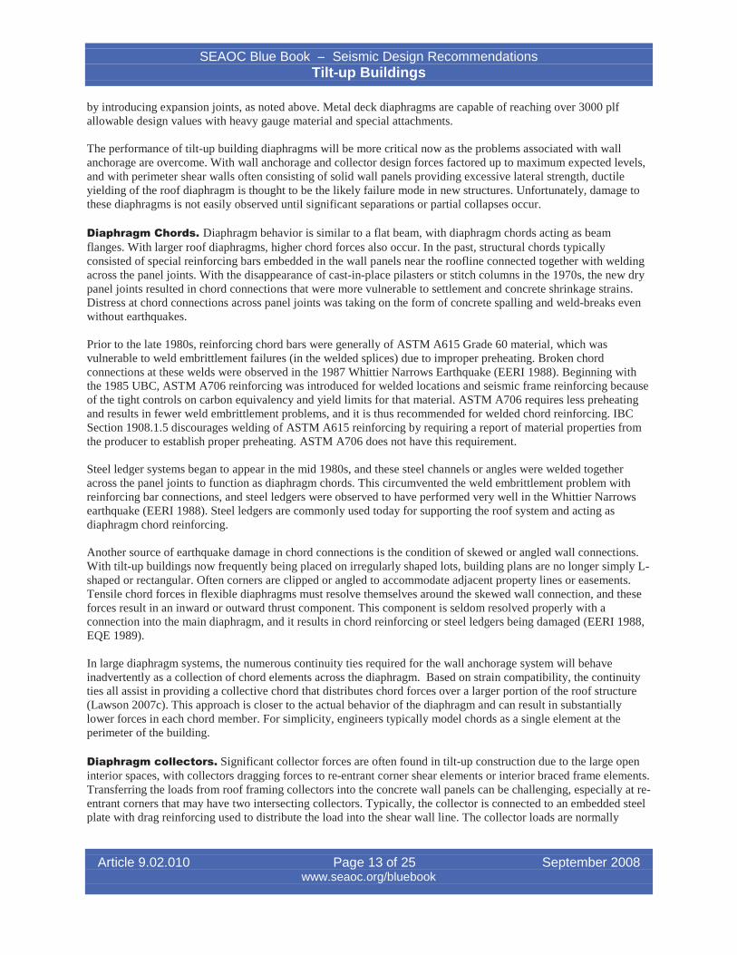
The performance of tilt-up building diaphragms will be more critical now as the problems associated with wallanchorage are overcome. With wall anchorage and collector design forces factored up to maximum expected levels,and with perimeter shear walls often consisting of solid wall panels providing excessive lateral strength, ductileyielding of the roof diaphragm is thought to be the likely failure mode in new structures. Unfortunately, damage tothese diaphragms is not easily observed until significant separations or partial collapses occur.
Diaphragm Chords. Diaphragm behavior is similar to a flat beam, with diaphragm chords acting as beamflanges. With larger roof diaphragms, higher chord forces also occur. In the past, structural chords typicallyconsisted of special reinforcing bars embedded in the wall panels near the roofline connected together with weldingacross the panel joints. With the disappearance of cast-in-place pilasters or stitch columns in the 1970s, the new drypanel joints resulted in chord connections that were more vulnerable to settlement and concrete shrinkage strains.Distress at chord connections across panel joints was taking on the form of concrete spalling and weld-breaks evenwithout earthquakes.
Prior to the late 1980s, reinforcing chord bars were generally of ASTM A615 Grade 60 material, which wasvulnerable to weld embrittlement failures (in the welded splices) due to improper preheating. Broken chordconnections at these welds were observed in the 1987 Whittier Narrows Earthquake (EERI 1988). Beginning withthe 1985 UBC, ASTM A706 reinforcing was introduced for welded locations and seismic frame reinforcing becauseof the tight controls on carbon equivalency and yield limits for that material. ASTM A706 requires less preheatingand results in fewer weld embrittlement problems, and it is thus recommended for welded chord reinforcing. IBCSection 1908.1.5 discourages welding of ASTM A615 reinforcing by requiring a report of material properties fromthe producer to establish proper preheating. ASTM A706 does not have this requirement.
Steel ledger systems began to appear in the mid 1980s, and these steel channels or angles were welded togetheracross the panel joints to function as diaphragm chords. This circumvented the weld embrittlement problem withreinforcing bar connections, and steel ledgers were observed to have performed very well in the Whittier Narrowsearthquake (EERI 1988). Steel ledgers are commonly used today for supporting the roof system and acting asdiaphragm chord reinforcing.
Another source of earthquake damage in chord connections is the condition of skewed or angled wall connections.With tilt-up buildings now frequently being placed on irregularly shaped lots, building plans are no longer simply Lshaped or rectangular. Often corners are clipped or angled to accommodate adjacent property lines or easements.Tensile chord forces in flexible diaphragms must resolve themselves around the skewed wall connection, and theseforces result in an inward or outward thrust component. This component is seldom resolved properly with aconnection into the main diaphragm, and it results in chord reinforcing or steel ledgers being damaged (EERI 1988,EQE 1989).
In large diaphragm systems, the numerous continuity ties required for the wall anchorage system will behaveinadvertently as a collection of chord elements across the diaphragm. Based on strain compatibility, the continuityties all assist in providing a collective chord that distributes chord forces over a larger portion of the roof structure(Lawson 2007c). This approach is closer to the actual behavior of the diaphragm and can result in substantiallylower forces in each chord member. For simplicity, engineers typically model chords as a single element at theperimeter of the building.
Diaphragm collectors. Significant collector forces are often found in tilt-up construction due to the large openinterior spaces, with collectors dragging forces to re-entrant corner shear elements or interior braced frame elements.Transferring the loads from roof framing collectors into the concrete wall panels can be challenging, especially at reentrant corners that may have two intersecting collectors. Typically, the collector is connected to an embedded steelplate with drag reinforcing used to distribute the load into the shear wall line. The collector loads are normally
Article 9.02.010 Page 13 of 25 September 2008www.seaoc.org/bluebook
SEAOC Blue Book – Seismic Design RecommendationsTilt-up Buildings
dragged across panel joints in order to distribute the collected diaphragm load into sufficient wall length. Thecollector load in the roof structure is subject to the special load combinations referenced in ASCE 7-05 Section12.4.3.2.
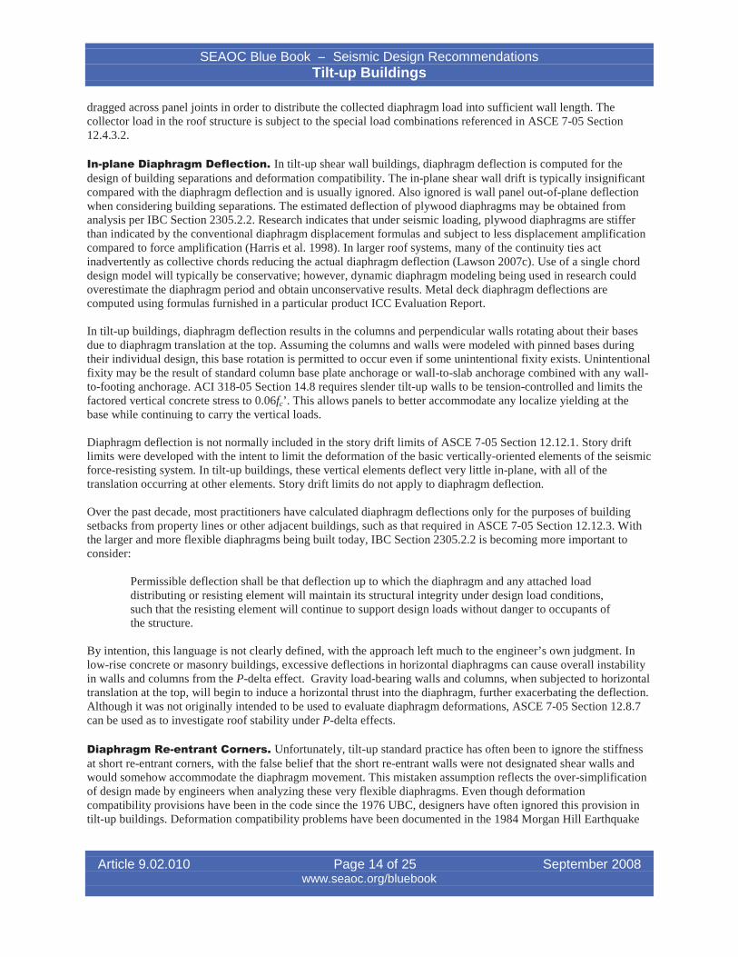
In-plane Diaphragm Deflection. In tilt-up shear wall buildings, diaphragm deflection is computed for thedesign of building separations and deformation compatibility. The in-plane shear wall drift is typically insignificantcompared with the diaphragm deflection and is usually ignored. Also ignored is wall panel out-of-plane deflectionwhen considering building separations. The estimated deflection of plywood diaphragms may be obtained fromanalysis per IBC Section 2305.2.2. Research indicates that under seismic loading, plywood diaphragms are stifferthan indicated by the conventional diaphragm displacement formulas and subject to less displacement amplificationcompared to force amplification (Harris et al. 1998). In larger roof systems, many of the continuity ties actinadvertently as collective chords reducing the actual diaphragm deflection (Lawson 2007c). Use of a single chorddesign model will typically be conservative; however, dynamic diaphragm modeling being used in research couldoverestimate the diaphragm period and obtain unconservative results. Metal deck diaphragm deflections arecomputed using formulas furnished in a particular product ICC Evaluation Report.
In tilt-up buildings, diaphragm deflection results in the columns and perpendicular walls rotating about their basesdue to diaphragm translation at the top. Assuming the columns and walls were modeled with pinned bases duringtheir individual design, this base rotation is permitted to occur even if some unintentional fixity exists. Unintentionalfixity may be the result of standard column base plate anchorage or wall-to-slab anchorage combined with any wallto-footing anchorage. ACI 318-05 Section 14.8 requires slender tilt-up walls to be tension-controlled and limits thefactored vertical concrete stress to 0.06fc’. This allows panels to better accommodate any localize yielding at thebase while continuing to carry the vertical loads.
Diaphragm deflection is not normally included in the story drift limits of ASCE 7-05 Section 12.12.1. Story driftlimits were developed with the intent to limit the deformation of the basic vertically-oriented elements of the seismicforce-resisting system. In tilt-up buildings, these vertical elements deflect very little in-plane, with all of thetranslation occurring at other elements. Story drift limits do not apply to diaphragm deflection.
Over the past decade, most practitioners have calculated diaphragm deflections only for the purposes of buildingsetbacks from property lines or other adjacent buildings, such as that required in ASCE 7-05 Section 12.12.3. Withthe larger and more flexible diaphragms being built today, IBC Section 2305.2.2 is becoming more important toconsider:
Permissible deflection shall be that deflection up to which the diaphragm and any attached loaddistributing or resisting element will maintain its structural integrity under design load conditions,such that the resisting element will continue to support design loads without danger to occupants ofthe structure.
By intention, this language is not clearly defined, with the approach left much to the engineer’s own judgment. Inlow-rise concrete or masonry buildings, excessive deflections in horizontal diaphragms can cause overall instabilityin walls and columns from the P-delta effect. Gravity load-bearing walls and columns, when subjected to horizontaltranslation at the top, will begin to induce a horizontal thrust into the diaphragm, further exacerbating the deflection.Although it was not originally intended to be used to evaluate diaphragm deformations, ASCE 7-05 Section 12.8.7can be used as to investigate roof stability under P-delta effects.
Diaphragm Re-entrant Corners. Unfortunately, tilt-up standard practice has often been to ignore the stiffnessat short re-entrant corners, with the false belief that the short re-entrant walls were not designated shear walls andwould somehow accommodate the diaphragm movement. This mistaken assumption reflects the over-simplificationof design made by engineers when analyzing these very flexible diaphragms. Even though deformationcompatibility provisions have been in the code since the 1976 UBC, designers have often ignored this provision intilt-up buildings. Deformation compatibility problems have been documented in the 1984 Morgan Hill Earthquake
Article 9.02.010 Page 14 of 25 September 2008www.seaoc.org/bluebook
SEAOC Blue Book – Seismic Design RecommendationsTilt-up Buildings
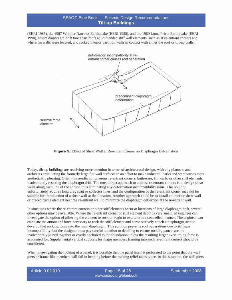
(EERI 1985), the 1987 Whittier Narrows Earthquake (EERI 1988), and the 1989 Loma Prieta Earthquake (EERI1990), where diaphragm drift tore apart roofs at unintended stiff wall elements, such as at re-entrant corners andwhere fin walls were located, and racked interior partition walls in contact with either the roof or tilt-up walls.
deformation incompatibility at re-entrant corner causes roof separation
seismic forcedirection
predominant diaphragmdeformation
Figure 5. Effect of Shear Wall at Re-entrant Corner on Diaphragm Deformation
Today, tilt-up buildings are receiving more attention in terms of architectural design, with city planners andarchitects articulating the formerly large flat wall surfaces in an effort to make industrial parks and warehouses moreaesthetically pleasing. Often this results in numerous re-entrant corners, buttresses, fin walls, or other stiff elementsinadvertently resisting the diaphragm drift. The most direct approach to address re-entrant corners is to design shearwalls along each line of the corner, thus eliminating any deformation incompatibility issue. This solutionunfortunately requires long drag strut or collector lines, and the configuration of the re-entrant corner may not besuitable for introduction of a shear wall at that location. Another approach could be to install an interior shear wallor braced frame element near the re-entrant wall to minimize the diaphragm deflection at the re-entrant wall.
In situations where the re-entrant corners or other stiff elements occur at locations of large diaphragm drift, severalother options may be available. Where the re-entrant corner or stiff element depth is very small, an engineer caninvestigate the option of allowing the element to rock or begin to overturn in a controlled manner. The engineer cancalculate the amount of force necessary to rock the stiff element and conservatively attach a diaphragm strut todevelop that rocking force into the main diaphragm. This solution prevents roof separations due to stiffnessincompatibility, but the designer must pay careful attention to detailing to ensure rocking panels are notinadvertently joined together or overly anchored to the foundation unless the resulting larger overturning force isaccounted for. Supplemental vertical supports for major members framing into such re-entrant corners should beconsidered.
When investigating the rocking of a panel, it is possible that the panel itself is perforated to the point that the wallpiers or frame-like members will fail in bending before the rocking relief takes place. In this situation, the wall piers
Article 9.02.010 Page 15 of 25 September 2008www.seaoc.org/bluebook
SEAOC Blue Book – Seismic Design RecommendationsTilt-up Buildings
must maintain their integrity and are detailed under ACI 318-05 Section 21.11 for frame members not proportionedto resist forces induced by earthquake motions. The re-entrant panel is still connected to the roof structure to developthe load into the diaphragm necessary to achieve the pushover capacity of the piers.
Other solutions may involve the use of seismic isolation or expansion joints in the roof structure. Depending uponthe configuration, the offending re-entrant elements can be isolated from the main diaphragm movement, howeverthis requires the isolated portions of the building to remain stable on their own.
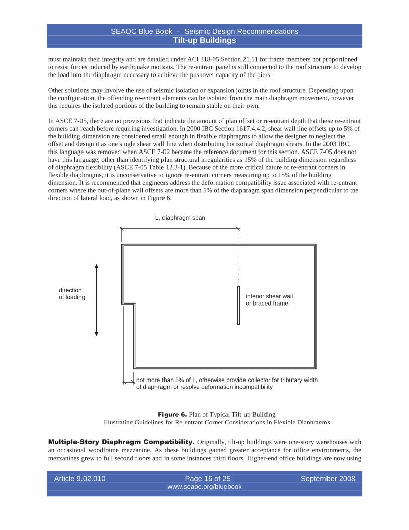
In ASCE 7-05, there are no provisions that indicate the amount of plan offset or re-entrant depth that these re-entrantcorners can reach before requiring investigation. In 2000 IBC Section 1617.4.4.2, shear wall line offsets up to 5% ofthe building dimension are considered small enough in flexible diaphragms to allow the designer to neglect theoffset and design it as one single shear wall line when distributing horizontal diaphragm shears. In the 2003 IBC,this language was removed when ASCE 7-02 became the reference document for this section. ASCE 7-05 does nothave this language, other than identifying plan structural irregularities as 15% of the building dimension regardlessof diaphragm flexibility (ASCE 7-05 Table 12.3-1). Because of the more critical nature of re-entrant corners inflexible diaphragms, it is unconservative to ignore re-entrant corners measuring up to 15% of the buildingdimension. It is recommended that engineers address the deformation compatibility issue associated with re-entrantcorners where the out-of-plane wall offsets are more than 5% of the diaphragm span dimension perpendicular to thedirection of lateral load, as shown in Figure 6.
L, diaphragm span
interior shear wallor braced frame
directionof loading
not more than 5% of L, otherwise provide collector for tributary widthof diaphragm or resolve deformation incompatibility
Figure 6. Plan of Typical Tilt-up BuildingIllustrating Guidelines for Re-entrant Corner Considerations in Flexible Diaphragms
Multiple-Story Diaphragm Compatibility. Originally, tilt-up buildings were one-story warehouses withan occasional woodframe mezzanine. As these buildings gained greater acceptance for office environments, themezzanines grew to full second floors and in some instances third floors. Higher-end office buildings are now using
Article 9.02.010 Page 16 of 25 September 2008www.seaoc.org/bluebook
I
SEAOC Blue Book – Seismic Design RecommendationsTilt-up Buildings
concrete floor systems over metal deck, while the roof system remains a flexible panelized wood roof or metal deckroof.
With concrete panels extending full height continuously past the upper floor, diaphragm deflection incompatibilitiesbetween the roof and floor diaphragms can lead to panel damage or anchorage failure. This type of damage was firstobserved in the 1989 Loma Prieta Earthquake where a full-height wall panel was anchored to both the roof andsecond floor. The panel experienced cracking along the second floor level, indicating the initiation of a horizontalhinge (SEAOC 1991).
For analytical purposes, engineers normally ignore wall continuity and assume the panel hinges at the intermediatefloor lines, thus anchoring the out-of-plane wall load based on simple tributary wall areas to the floor and rooflevels. In this situation, some cracking and hinging of the panel at the intermediate floor line is anticipated understrong shaking levels, and this is acceptable as long as the axial gravity loads are still characteristically small(limited by ACI 318-05 Section 14.8.2.6) and the wall panel is sufficiently flexible out-of-plane. A worse scenario isif the wall is excessively stiff out-of-plane and the relative roof and floor movements pry the wall anchorage loosecausing a localized collapse. In conditions where diaphragm drift significantly varies from floor-to-floor or floor-toroof, the designer should investigate the wall anchorage capacity for this additional effect by analyzing deformationcompatibilities or designing the stability of the floor to be independent of the concrete wall system.
Is Tilt-up Construction Precast or Cast-in-Place?In the past, tilt-up engineering has generally followed design and detailing provisions as for monolithic concrete.Precast concrete buildings were traditionally considered as structures comprised of numerous small concretemembers cast at an off-site plant and transported to the jobsite for assemblage. Individual beam, column, plank, andnarrow wall members are traditional precast elements, and ACI 318 precast concrete provisions were developedwith that construction type primarily in mind. Generally, the joining of beams to columns for frame resistance or thecoupling of narrow wall elements together for composite shear wall resistance represents traditional precast concreteresistance to seismic forces. In traditional precast construction, the individual element has little or no lateralresistance on its own, but relies upon the assemblage to achieve lateral resistance.
In contrast to traditional precast, concrete tilt-up construction consists of panels that are individually stable wallelements that seldom require coupling devices for composite action. Penetrations within walls are surrounded bydeep beams above which in turn are monolithically cast to wall pier elements at the sides. The only discontinuitiesare at the vertical panel joints, often twenty or thirty feet apart, and at the panel-to-footing interface. Historically, thein-plane performance and ductility of this lateral force resisting system is closer to cast-in-place construction thantraditional precast.
The ACI 318-05 defines precast concrete in Section 2.2 as a "Structural concrete element cast elsewhere thanits final position in the structure." Under this broad definition, tilt-up concrete construction could beconsidered as site-cast precast. In fact, the tilt-up concrete construction method was first discussed in ACI318-95 in the Commentary for precast concrete stating, "Tilt-up concrete construction is a form of precastconcrete."
In ASCE 7-05 Table 12.2-1, "Design Coefficients and Factors for Seismic Force-Resisting Systems," there are nowthree categories under the heading for Bearing Wall Systems and for Building Frame Systems that potentially applyto tilt-up buildings as a form of precast concrete construction. These are Ordinary Precast Shear Walls, IntermediatePrecast Shear Walls, and Special Reinforced Concrete Shear Walls. The category of Intermediate Precast ShearWalls is new and represents a transition in detailing and expected performance between ordinary and specialsystems. ACI 318-05 Commentary 21.1 indicates that the Intermediate Precast Shear Wall system is equivalent to aCast-in-Place Ordinary Reinforced Concrete Shear Wall. However, ASCE 7-05 places height limits on theIntermediate Precast system in Seismic Design Categories D, E, and F, whereas Ordinary Reinforced ConcreteShear Walls are not permitted in Seismic Design Categories D, E, and F per ASCE 7-05; Intermediate Precast ShearWalls are permitted recognizing their additional wall pier detailing requirements and height limits. 2006 IBC
Article 9.02.010 Page 17 of 25 September 2008www.seaoc.org/bluebook
SEAOC Blue Book – Seismic Design RecommendationsTilt-up Buildings
1908.1.8 gives detailing requirements for a special wall pier when design is based on ACI 318 Sec. 21.7, while IBC1908.1.13 gives requirements for wall pier detailing when design is based on ACI 318 Sec. 21.13. As discussed laterunder Wall Pier and Shear Wall Classifications, the provision prescribed under IBC 1908.1.8 was introduced bySEAOC in legacy code for high seismic regions (SDC D, E or F), while the later provision prescribed under IBC1908.1.13 has been introduced by others for lower seismic region (SDC C.)
With the lack of the word “precast,” the applicability of the Special Reinforced Concrete Shear Wall category to tilt-up buildings may not be immediately obvious, but a quick reference to ACI 318-05 will clarify this application. Theintent of ACI 318-05 toward the proper classification of Structural Walls can be obtained by reviewing theprovisions in conjunction with the Commentary. Chapter 21 of ACI 318-05, Special Provisions for Seismic Design,Section 21.1 - Definitions, provides the following guidance. Structural Walls are defined as "Walls proportioned toresist combinations of shears, moments, and axial forces induced by earthquake motions. A shear wall is a structuralwall. Structural walls shall be categorized as follows." A Special Precast Structural Wall is defined as "A precastwall complying with the requirements of 21.8. In addition, the requirements for ordinary reinforced concretestructural walls and the requirements of 21.2.2.3, 21.2.3 through 21.2.7, and 21.7 shall be satisfied." Thecommentary for this definition states, "The provisions of 21.8 are intended to result in a special precast structuralwall having minimum strength and toughness equivalent to that for a special reinforced concrete structural wall ofcast-in-place concrete." Therefore this establishes that a Special Precast Structural Wall is equivalent to a SpecialReinforced Concrete Structural Wall.
Development of precast concrete seismic design provisions has been based on extensive research which resulted indevelopment of acceptance criteria described in 2003 in FEMA 450-2, Commentary section 9.6 (BSSC 2004a).Hawkins and Ghosh (2004) provide information on testing research on this topic. Much of the research work hasbeen directed toward investigating the seismic performance of traditional precast concrete structures with improvedconnections. The landmark research associated with the PRESSS (Precast Seismic Structural Systems) ResearchProgram has greatly influenced the specific ACI 318 seismic provisions for precast concrete systems. ACI 318-05Sec. 21.8 provisions on special structural walls constructed using precast concrete, however, was not written for tilt-up wall construction (Ghosh and Hawkins 2006).
The development of the special precast concrete system was separate from the over fifty-year development of theconcrete tilt-up system. The current code language is ambiguous, because ACI 318 Chapter 21 encourages ductiledetailing, including confinement reinforcement and development of tensile reinforcement in high-seismic regions.SEAOC believes a new system approach for tilt-up system is needed. During the interim, SEAOC affirms properload path and ductile detailing practice be followed in the design and detailing of tilt-up panels.
Shear Distribution in Walls Loaded In-PlaneComplex panel configurations and the wall panels with extensive perforations are relatively recent developments.Originally, designers had ample amounts of solid wall panels to use or “designate” as acting as shear walls. Often,there was enough overstrength along a wall line that little attention was paid to exact force distribution among thewall panels. It was common to simply divide the total wall line shear equally into each panel or proportional to panellength, accounting somewhat for the openings. Even though past codes required that forces be distributed inproportion to element stiffnesses, engineers justified designs by demonstrating adequacy of the collective wall lineas a whole. A series of individual panels modeled together with multiple opening configurations and numerous paneljoints made modeling too complex without computers for the average engineer.
Today, with computer usage common and essential in the office, engineers have enough computing power to betterdistribute shear loads along complicated shear wall lines in proportion to individual panel rigidities as described byASCE 7-05 Section 12.8.4, considering both shear and flexural stiffnesses. Accurate distribution of in-plane shearforces along designated shear wall lines has become quite complex as buildings use more complex panelconfigurations with numerous openings. The classic conventional rigidity analysis often used for walls in poured-inplace concrete or masonry construction is not necessarily accurate for tilt-up walls unless each panel joint is alsoconsidered. The combination of repeating panel joints, various opening arrangements, thickened wall sections,
Article 9.02.010 Page 18 of 25 September 2008www.seaoc.org/bluebook
SEAOC Blue Book – Seismic Design RecommendationsTilt-up Buildings
sloping roof heights and partially cracked concrete properties result in a very difficult analysis if distributionaccuracy is paramount. Normally, the distribution may be simplified by assuming average roof heights, averagepanel thicknesses, and uncracked concrete properties.
Recognizing that stiff shear wall elements could become overloaded, crack, and redistribute their loads to othermore flexible wall pier elements (see wall pier discussion below), wall piers are required to be detailed to ensureflexural yield failure unless the sum of the shear wall stiffnesses is at least six times greater than the sum of wall pierstiffnesses (IBC 1908.1.8).
Another possible approach used to further simplify the distribution of in-plane shears is to designate solid panelsalong a wall line as the primary shear walls for the total wall line shear. This simplifies the distribution by ignoringthe more flexible panels and transferring the entire seismic load to a few stiffer and stronger panels through acollector. By ignoring portions of the concrete wall line, these ignored elements may be subject to the provisions ofACI 318-05 Section 21.11 for concrete members not designated as part of the lateral force-resisting system. Thespecial detailing of these “ignored” members will provide more ductile behavior in the event that the solid wallscrack or rock under overload and redistribute the seismic forces.
A method used by some engineers can be described as the “flexible-link” approach. This method assumes that thechord connections between panels can be designed to contain enough stretch or flexibility to effectively isolate orbuffer the individual panels from each other (Eddington 1990, Brooks 2000). Truly isolated panels wouldtheoretically only see seismic forces from the tributary diaphragm length in contact with the panel and forces fromthe panel seismic self-weight. The flexible link is a panel-to-panel chord connection that has significantly moreflexibility than the differences in flexibilities between panels, so that the chord stretch deformation dominates anyrelative drift differences between panels. It is common in tilt-up construction to prevent the bonding of the chordreinforcing (or slot the continuous steel ledger bolting) in the vicinity of panel joints to help relieve thermal andshrinkage strains that develop. With this approach, the unbonded chord length that crosses a standard ½ in or ¾ inpanel joint is considered the flexible-link buffer. Of course this flexible link must still have sufficient stiffness to beeffective against chord forces without excessive diaphragm deflections, and analysis complications occur whencollectors at re-entrant corners apply large seismic drag loads to the end panel of a wall line.
As just discussed, there are several available methods to distributing seismic shears within the shear wall system.ASCE 7-05 Section 12.8.4 states that seismic story shears shall be distributed to the various vertical elements of theseismic force-resisting system based on the relative lateral stiffness of the resisting elements and diaphragm. The2003 NEHRP Commentary (Section 5.2.4) states, “Reasonable and consistent assumptions regarding the stiffness ofconcrete and masonry elements may be used for analysis in distributing the shear force to such elements connectedby a horizontal diaphragm.” Regardless of which assumptions are used to distribute in-plane shears, adequate lifesafety protection is expected under the actual distribution as long as a rational distribution approach is used and thedetailing requirements associated with wall piers and frame elements are implemented. This is an area that couldbenefit from further research.
Wall Pier and Shear Wall ClassificationsTraditionally, tilt-up buildings contained many solid wall panels that easily fit the definition of shear walls.However, as greater architectural demands on tilt-up buildings pushed doors and window closer together and closerto panel joints, the remaining wall piers became narrower and more frame-like. Building codes gave little guidancein classifying whether narrow wall segments were better judged as frames or shear walls, and building departmentsbegan to see tilt-up wall-frame like structures being designed under the more relaxed shear wall requirements.
In defining the different types of lateral force-resisting systems, concrete wall-framed type systems such as tilt-upbuildings with deep spandrels above repeating sizeable openings have not been recognized and have no assignedseismic response R-factor. Codes prior to 1991 did not include lower-bound limits on shear wall lengths, and did notadequately cover the design and detailing of slender and narrow shear wall segments. Observed earthquake damagein cast-in-place and precast shear walls repeatedly showed distress due to short-column effects in narrow wall piers
Article 9.02.010 Page 19 of 25 September 2008www.seaoc.org/bluebook
SEAOC Blue Book – Seismic Design RecommendationsTilt-up Buildings
and showed a need for adequate transverse reinforcement. SEAOC Seismology Committee introduced a codechange that was adopted into the 1991 UBC. Most of the original provisions sustained transition from UBC to 2006IBC in defining regions that need special transverse reinforcement in wall piers in order to confine longitudinal wallreinforcement when subjected to in-plane seismic shear force. While IBC Section 1908.1.8 includes the wall pierprovisions from the 1997 UBC, similar language has not been incorporated into ACI 318-05.
Wall panels supporting deep spandrels are similar to columns supporting discontinuous shear walls. When a wallsegment with the length-to-thickness aspect ratio exceeds 2.5 and the compressive axial force including earthquakeis less than Agf’c/20, the wall pier design provisions should be met. The design shear force, Ve , should bedetermined by considering the probable flexural strength, Mpr , of the wall pier, based on the reinforcement tensilestress of 1.25fy and a capacity reduction factor equal to one, and dividing by the clear height of the opening.
The minimum length-to-thickness aspect ratio was chosen to ensure flexural behavior of the wall segment. A wallsegment that does not meet the prescribed aspect ratio may be designed as flexural frame members under ACI 31805 Section 21.3 if lightly loaded axially and if it meets certain geometric limitations, otherwise the more restrictivecolumn requirements of ACI 318-05 Section 21.4 are necessary. In wall lines where only a few elements areclassified as columns, engineers have the option to ignore these members and classify them as “frame elements notproportioned to resist forces induced by earthquake motions” as long as they are detailed in accordance with ACI318-05 Section 21.11.
The special reinforcing provisions for wall piers are not required when those piers under consideration areadequately braced by other wall segments of substantially larger stiffness. Such lateral bracing elements must havelateral stiffness to resist the lateral deflections of the story such that any resulting deflection will not affect the wallpier strength substantially. The ratio for the sum of relative stiffnesses between wall bracing elements to those ofwall piers needs to be greater than or equal to six for the wall piers to be considered adequately braced. This wasoriginally proposed in the Blue Book and has been in use in California and in the Uniform Building Code for aconsiderable amount of time, without incident. Some have questioned this relative stiffness and have suggestedusing a value of 12 based on a proposed code change in ACI 318 section 10.10.1 on the slenderness effect ofcompression members. At the present time, however, there are neither tests nor documented data known to theSeismology Committee to justify an increase from the original value of six.
Research done on thin tilt-up frame panels (similar to wall piers) has shown the benefits of close tie spacing in thehinge zone where flexural yielding initiates. Cyclic loading tests of full-scale tilt-up specimens provide insight intothe behavior of wall piers that have various tie spacings. Four-inch tie spacing was effective in achieving ductilitywhereas eight-inch and twelve-inch spacings were not effective, allowing primary flexural steel to buckle (Dew,Sexsmith, and Weiler 2001).
Panel-to-Panel ConnectionsFrom its beginnings in the 1940s and into the 1970s, tilt-up wall panels were joined together with cast-in-placepilasters formed between adjacent panels. Horizontal panel reinforcing extended into the cast-in-place jointeffectively making all the panels behave almost as monolithic concrete. Since the 1970s, panels have been leftseparated with dry panel joints, but building designs still require connections across these joints for diaphragmchords and drag struts. In addition, some engineers provide connections across the joints for overturning resistance.
Intermittent connections across the panel joints are vulnerable to force concentrations from concrete shrinkagestrains and differential foundation settlement. The concrete panels are often lifted into place after only a week ofcuring with a substantial amount of concrete shrinkage potential remaining. Panels set on pad footings instead ofcontinuous footings are more subject to differential settlement. This potential for relative movement betweenindividual panels requires connections across these joints to be strong and well developed into the concrete toprevent brittle failure.
Article 9.02.010 Page 20 of 25 September 2008www.seaoc.org/bluebook
SEAOC Blue Book – Seismic Design RecommendationsTilt-up Buildings
Chord connections and drag connections typically involve the use of reinforcing steel or rolled steel shape ledgersdirectly spliced at the panel joints. To accommodate the shrinkage strains that can occur between panels, thecontinuous chord members are often detached from the panel in the vicinity of the joint to allow for horizontalmovement. In the case of reinforcing chord bars, the reinforcing is often wrapped or otherwise unbonded for a shortdistance from the panel joint. Where steel angle or channel ledgers are used, horizontally slotted bolt holes near thepanel joints are provided. These methods of chord detachment allow the horizontal strains to better relievethemselves elastically across the unbonded chord distance and reduce the likelihood of brittle weld failure orconcrete spalling at the connection.
Occasionally, overturning resistance of shear wall panels is supplemented with panel-to-panel embedmentconnections, effectively grouping adjacent panels together to behave as a whole. Often these connections are non-ductile with insufficient overstrength to prevent brittle concrete cone failure or weld rupture, and are not suitable inhigh seismic zones (Hofheins, Reaveley, and Pantelides 2002; Lemieux, Sexsmith, and Weiler 1998). Alternativelyfor overturning resistance, panels can be attached exclusively to the foundation for uplift forces allowing the panelsto more freely move at their joints. It is recommended that any panel-to-panel connections for uplift resistance beused sparingly and only if they are well developed into the concrete with reinforcing welds designed to fully developthe reinforcing bars. ACI 318-05 Section 21.8 for “Special structural walls constructed using precast concrete”references Sections 21.13.2 and 21.13.3 which require panel-to-panel connections to yield within the steel elementsor reinforcement, or otherwise be designed to develop at least 1½ times the connection yield strength. The SEAOCSeismology Committee recommends that panel-to-panel connections be designed with the Special Seismic LoadCombinations per 2006 IBC 1605.4 in lieu of developing only 1½ times the connection yield strength.
Wall Connections to the FoundationIn concrete tilt-up construction, many regional areas have seen tilt-up panels not attached to the spread footingfoundation that provides bearing support for the panels themselves. In these buildings, wall panels are verticallysupported on the foundation, but lateral forces are resisted only by panel connections to the slab-on-grade. Typicallythese connections consist of reinforcing dowels from the wall panel and from slab-on-grade that lap within a narrowconcrete pour-strip in the floor parallel to the wall panel.
ACI 318-05 Sections 15.8.3.2 and 16.5.1.3 allow precast concrete wall panels to forego the traditional footingconnection requirements that cast-in-place walls have in Section 15.8.2.2. The exclusive connection to the slab istheoretically permissible provided that a rational load path is established to transfer the in-plane and out-of-planeforces through the slab-on-grade and to the supporting soil.
However, slab-sliding resistance is difficult to predict, especially where a plastic moisture/vapor retarder is providedbelow the slab. Also, it is desirable to mobilize the lateral sliding strength of the foundations. For these reasons,SEAOC Seismology Committee issued a “Position Statement” strongly recommending that designs in highseismically active areas include either a direct or indirect connection to the foundation (SEAOC 2000). An exampleof an indirect connection would be panel dowels tied into the slab-on-grade and additional footing dowels also tiedinto the slab-on-grade. It is very common to see tilt-up panels with no foundation connection, yet there has not beenany reported damage associated with this in past earthquakes.
At heavily loaded shear walls, overturning may require an uplift connection from the wall panel directly to thefoundation. ACI 318-05 Section 21.8 for “Special structural walls constructed using precast concrete” referencesSections 21.13.2 and 21.13.3 which require panel-to-foundation connections to yield within the steel element orreinforcement, or otherwise be designed to develop at least 1½ times the connection yield strength.
New ThinkingPast performance of tilt-up buildings has been instrumental in making code revisions to wall anchorage andsubdiaphragm requirements, but the process has been a series of incremental reactionary changes that have simplyincreased the anchorage force or added prescriptive detailing language. There is a belief among some engineers and
Article 9.02.010 Page 21 of 25 September 2008www.seaoc.org/bluebook
SEAOC Blue Book – Seismic Design RecommendationsTilt-up Buildings
researchers that an entirely new approach may be needed in the seismic design of low-rise buildings with relativelyrigid vertical elements and with flexible diaphragms, such as is common with tilt-up and masonry buildings today.
Much of the current building code seismic provisions were developed with classic lumped masses at the floor androof assumed. The seismic response of the traditional lumped mass model is dominated by the stiffness of thevertically oriented lateral force-resisting system, and this assumption applies well to frame structures or tall shearwall structures with rigid heavy diaphragms.
Buildings with rigid shear wall systems supporting flexible diaphragms have several unique properties that makethem behave substantially different than classic framing types. The short concrete or masonry shear walls have verylittle flexibility compared with the diaphragm, and thus the diaphragm period dominates the overall building seismicresponse (Fonseca, Wood, and Hawkins 1996). Analytical modeling and research has shown that this seismicresponse can be accurately modeled and predicted (Fonseca, Hawkins, and Wood 1999).
In contrast, the equivalent lateral force analysis in ASCE 7-05, as well as the 2006 IBC, estimates building seismicresponse as a direct function of building height and the lateral force-resisting system stiffness of vertical structuralelements. In addition, current codes determine diaphragm and wall anchorage forces as a direct function of theground motion only, or sometimes in consideration of the vertical lateral force-resisting system stiffness, withoutany consideration of the dynamic response of the diaphragm. This inaccuracy in current codes has led some torecommend entirely new code provisions for use in rigid shear wall / flexible diaphragm buildings. Freeman, Searer,and Gilmartin (2002) provide a rational approach that computes seismic response more accurately, based ondiaphragm and wall out-of-plane periods. An approach similar to Freeman’s has merit and should be considered asthe basis for future code provisions. ASCE 7-05 Section 12.7.3 does provide general language for an alternativedynamic approach, however such a complex approach is not mandatory for typical tilt-up buildings and is outside ofnormal engineering practices.
Another unique aspect associated with rigid shear wall / flexible diaphragm buildings is that lack of diaphragmstiffness effectively isolates adjacent, parallel lines of shear resistance from each other. Unlike the case with non-flexible diaphragms, any softening or degradation of an overloaded shear wall that is beginning to fail cannot haveits loads effectively transferred across the diaphragm to adjacent lines of shear resistance until significant walltranslation has taken place. This amount of wall translation is likely to result in complete failure of the shear wallbefore any significant sharing of loads takes place among the other walls.
The implication is that the redundancy coefficient, U� governed by a redundancy weakness in only one line ofresistance, is very critical to that line, but need not impact the design of other parallel lines of resistance due to thediaphragm isolation effect. In a theoretical sense, U should apply only to specific lines of resistance judgedindependently, but the value of U should be higher to reflect the extra critical nature of the isolated problem beingunable to share the load through the flexible diaphragm to other parallel lines of resistance. However, someengineers argue that the purpose of U is not to apply a rational approach to strengthening non-redundant elements,but to penalize the entire building system as a discouragement to engineers.
Also related to the isolation effects of flexible diaphragms is the critical nature of struts or collectors in rigid shearwall / flexible diaphragm buildings. Again, because a failure in a collector line has limited ability to transfer loadsthrough the flexible diaphragm to other parallel collector lines, these collectors are non-redundant. ASCE 7-05Sections 12.10.2.1 and 12.4.3.2 have special load combination provisions for collectors that increase the designloads to address their critical nature. Rigid and semi-rigid diaphragms are more able to redistribute loads through thediaphragm should a collector failure occur, but current codes do not differentiate between the two in this regard.
Further research is justified for rigid shear wall / flexible diaphragm buildings, including tilt-up construction. A newapproach to code provisions governing this building type would allow a more rational consideration of buildingresponse, including appropriate provisions for redundancy coefficients, collector designs, deformation compatibilityissues, and diaphragm deflection limits.
Article 9.02.010 Page 22 of 25 September 2008www.seaoc.org/bluebook
SEAOC Blue Book – Seismic Design RecommendationsTilt-up Buildings
In 2005, the Tilt-Up Concrete Association (TCA) formed a seismic design task group as a proactive measure toadvance research on the unique dynamic behavior of this form of construction. Although the work of TCA is in itsinfancy, its collection of tilt-up construction experts and researchers has great potential in guiding future coderevisions. Additionally, in 2007 the University of British Columbia began a research program partially funded by thePortland Cement Association to study the dynamic behavior of tilt-up buildings and their connections as influencedwith flexible diaphragms.
As tilt-up construction continues to evolve architecturally and structurally, new questions arise for engineers toconsider. The state of the art in tilt-up design has made much progress over the last several decades, but importantquestions continue to be at hand for additional research:
Can a parallel set of seismic code provisions be developed for rigid shear wall / flexiblediaphragm buildings that considers more accurately their seismic response?
Is the selected method of distributing in-plane shears critical to shear wall performance?
Can a simplified method of shear distribution achieve acceptable results?
Are deformation limits for wall anchorage systems necessary, and if so, how should they be set?
As wall anchorage is eliminated as the weak element of tilt-up structures, will the mode offailure simply transfer to another vulnerable portion of the system?
ReferencesACI-SEAOSC (1982). Report of the task force on slender walls. American Concrete Institute (Southern California
Chapter) and the Structural Engineers Association of Southern California, Los Angeles, CA.AISI (2001). North American specification for design of cold-formed steel structural members. American Iron and
Steel Institute, Washington, DC.APA (1994). Northridge, California Earthquake, Report T94-5. APA - The Engineered Wood Association (formerly
the American Plywood Association), Tacoma, WA.ASCE (2006). Minimum design loads for buildings and other structures. ASCE/SEI 7-05. American Society of Civil
Engineers, Reston, VA.Bischoff, P. and Scanlon, A. (2007). “Effective moment of inertia for calculating deflections of concrete members
containing steel reinforcement and fiber-reinforced polymer reinforcement.” ACI Structural Journal, 104(1), January-February, 2007.
Bouwkamp, J., Hamburger, R.O., and Gillengerten, J. (1991). Degradation of plywood roof diaphragms undermultiple earthquake loading. CSMIP90, California Department of Conservation, Division of Mines andGeology (now California Geological Survey), Sacramento, CA.
Brooks, H. (2000). The tilt-up design and construction manual, 5th ed. Tilt-up Concrete Association, Mt. Vernon,IA.
BSSC (2004a). “Chapter 9, concrete structure requirements and commentary,” NEHRP recommended provisions forseismic regulations for new buildings and other structures, FEMA 450, 2003 ed., FEMA 450-1 and 450-2.Building Seismic Safety Council, Washington, DC.
BSSC (2004b). NEHRP recommended provisions for seismic regulations for new buildings and other structures,FEMA 450, 2003 ed., Part 2, Commentary, Building Seismic Safety Council, Washington, DC.
Çelebi, M. et al. (1989). “Seismic response of large-span roof diaphragms.” Earthquake Spectra. 5 (2). EarthquakeEngineering Research Institute, Oakland, CA.
CSSC, 1995. Northridge Earthquake, turning loss to gain, SSC Report No. 95-01. California Seismic SafetyCommission, Sacramento, CA.
Dew, M., Sexsmith, R., and Weiler, G. (2001). “Effect of hinge zone tie spacing on ductility of concrete tilt-upframe panels.” ACI Structural Journal 98 (6), November-December, 2001.
Article 9.02.010 Page 23 of 25 September 2008www.seaoc.org/bluebook
SEAOC Blue Book – Seismic Design RecommendationsTilt-up Buildings
Eddington, Ronald (1990). “The flexible link.” From experience. Structural Engineers Association of CentralCalifornia, Sacramento, CA.
EERI (1985). “The Morgan Hill Earthquake of April 24, 1984,” Earthquake Spectra. (1) 3. Earthquake EngineeringResearch Institute, Oakland, CA.
EERI (1988). “The Whittier Narrows Earthquake of October 1, 1987.” Earthquake Spectra 4 (2). EarthquakeEngineering Research Institute, Oakland, CA.
EERI (1990). “Loma Prieta Earthquake reconnaissance Report.” Earthquake Spectra. Supplement to Volume 6.Earthquake Engineering Research Institute, Oakland, CA.
EERI (1996). “Northridge Earthquake reconnaissance report, vol.2.” Earthquake Spectra. Supplement C to vol. 11.Earthquake Engineering Research Institute, Oakland, CA.
EQE (1989). The October 17, 1989 Loma Prieta Earthquake. EQE Engineering, San Francisco, CA.EQE (1987). Summary of the October 1, 1987 Whittier, California Earthquake. EQE Engineering, San Francisco,
CA.Fonseca, F.S., Wood, S.L., and Hawkins, N.M. (1996). “Measured response of roof diaphragms and wall panels in
tilt-up systems subjected to cyclic loading.” Earthquake Spectra. 12 (4). Earthquake Engineering ResearchInstitute, Oakland, CA.
Fonseca, F.S., Hawkins, N.M., and Wood, S.L. (1999). “Calculated response of tilt-up structures.” Proceedings ofthe 8th Canadian Conference on Earthquake Engineering. Vancouver, British Columbia, June, 1999.
Freeman, S.A., Searer, G.R., and Gilmartin, U.M. (2002). “Proposed seismic design provisions for rigid shear wall /flexible diaphragm structures." Proceedings of the Seventh U.S. National Conference on EarthquakeEngineering (7NCEE). Earthquake Engineering Research Institute, Oakland, CA.
Gilbert, R.I (2001). “Deflection calculation and control – Australian code amendments and improvements.” Codeprovisions for deflection controls in concrete structures, SP 203-4, American Concrete Institute,Farmington Hills, MI.
Ghosh, S.K., and Hawkins, N. M. (2006). “Codification of precast seismic structural systems: An update,” PCIJournal 51 (3), May-June, p. 2-5.
Hamburger, R.O. and Nelson, R.F. (1999). “Hold-down eccentricity and the capacity of the vertical wood member,”Building Standards, November-December, 1999. International Conference of Building Officials, Whittier,CA.
Harris, S. K. et al. (1998). “Response of tilt-up buildings to seismic demands: Case studies from the 1994 NorthridgeEarthquake.” Proceedings of the NEHRP Conference and Workshop on Research on the Northridge,California Earthquake of January 17, 1994. California (now Consortium of) Universities for Research inEarthquake Engineering (CUREE), Richmond, CA.
Hawkins, N. M. and Ghosh, S. K. (2004). “Acceptance criteria for special concrete structural walls based onvalidation testing.” PCI Journal, 49 (5), September – October, p. 78-92.
Hofheins, C.L., Reaveley, L.D., and Pantelides, C.P. (2002). “Behavior of welded plate connections in precastconcrete panels under simulated seismic loads." PCI Journal, July-August 2002. Precast/PrestressedConcrete Institute, Chicago, IL.
ICBO (1967, 1973, 1976, 1985, 1988, 1991, 1994, 1997). Uniform building code. International Conference ofBuilding Officials, Whittier, CA.
ICBO (2001). Guidelines for seismic retrofit of existing buildings, International Conference of Building Officials,Whittier, CA.
ICBO (2002). Acceptance criteria for joist hangers and similar devices, AC13. January 2002. ICBO EvaluationService, Inc., Whittier, CA.
ICC (2000). International building code. International Code Council, Falls Church, VA.ICC (2003). International building code. International Code Council, Falls Church, VA.ICC (2006). International building code. International Code Council, Falls Church, VA.Kripanarayanan, K. M. (1974). "Tilt-up load-bearing walls: A design aid." PCA Engineering Bulletin, Portland
Cement Association, Skokie, IL.LA City (2002). “Chapter 91 – Earthquake hazard reduction in existing tilt-up concrete wall buildings,” 2002 City of
Los Angeles building code. International Conference of Building Officials, Whittier, CA.LA County (2002). “Chapter 95 - Earthquake hazard reduction for existing concrete tilt-up buildings,” 2002 County
of Los Angeles building code. International Conference of Building Officials, Whittier, CA.
Article 9.02.010 Page 24 of 25 September 2008www.seaoc.org/bluebook
SEAOC Blue Book – Seismic Design RecommendationsTilt-up Buildings
LADBS (2002). "Wall anchorage assemblies to flexible diaphragms – Revised design criteria," Information BulletinP/BC 2001-71 November 1, 2002. Los Angeles Department of Building and Safety, Los Angeles, CA.
Lawson, John (2007a). “A call for unified design – Deflection limits for tilt-up wall serviceability.” StructuralEngineer. January 2007, Zweig White Information Services, Chicago, IL.
Lawson, John (2007b). “Deflection limits for tilt-up wall serviceability – The history behind changes to Chapter 14of ACI 318.” Concrete International, 29 (9). American Concrete Institute, September 2007.
Lawson, John (2007c). “Thinking outside the box: New approaches to very large flexible diaphragms.” SEAOC2007 Convention Proceedings, Structural Engineers Association of California, Sacramento, CA.
Lemieux, K., Sexsmith, R., Weiler, G. (1998). “Behavior of embedded steel connectors in concrete tilt-up panels.”ACI Structural Journal, July-August, 1998.
Mayo, John L. (2001). “Metal roof construction on large warehouses or distribution centers.” Steel Tips. June 2001,Structural Steel Education Council, Moraga, CA.
NOAA (1971). San Fernando, California, Earthquake of February 9, 1971, vol. 1. National Oceanic andAtmospheric Administration, Washington DC.
Scanlon, A., and Murray, D. (1982). “Practical calculation of two-way slab deflections." Concrete International, 4(11). American Concrete Institute, 1982.
Scanlon, A. and Bischoff, P. (2007). “Shrinkage restraint and loading history effects on deflection of flexuralmembers.” Submitted to ACI Structural Journal, February 2007.
SEAOC (1991). Reflections on the Loma Prieta Earthquake October 17, 1989. Structural Engineers Association ofCalifornia, Sacramento, CA.
SEAOC Seismology Committee (1999). Recommended lateral force requirements and commentary – 7th ed.Structural Engineers Association of California, Sacramento, CA.
SEAOC (2000). Position statement: Tilt-up wall connections to footings, Structural Engineers Association ofCalifornia, Seismology and ad-hoc Tilt-Up Committees, Sacramento, CA.
SEAONC (2001). Guidelines for seismic evaluation and rehabilitation of tilt-up buildings and other rigidwall/flexible diaphragm structures, Structural Engineers Association of Northern California andInternational Conference of Building Officials.
SEAOSC (1979). Recommended tilt-up wall design. Structural Engineers Association of Southern California, LosAngeles, CA.
SEAOSC (2006). UBC 97 and ACI 318-02 code comparison summary report. January 2006. SEAOSC Slender WallTask Group, Structural Engineers Association of Southern California, Los Angeles, CA.
Sheedy, P. and Sheedy, C. (1992). “Concrete and Masonry Wall Anchorage.” Building Standards, July-August,1992. International Conference of Building Officials, Whittier, CA.
Keywordsconcrete shear wallsflexible diaphragmlow-rise constructiontilt-upwood diaphragmsteel deck diaphragm
How To Cite This PublicationIn the writer’s text, this article should be cited as:
(SEAOC Seismology Committee 2008)
In the writer’s reference list, the reference should be listed as:
SEAOC Seismology Committee (2008). “Tilt-up buildings,” September, 2008, The SEAOC Blue Book:Seismic design recommendations, Structural Engineers Association of California, Sacramento, CA. Accessible viathe world wide web at: http://www.seaoc.org/bluebook/index.html
Article 9.02.010 Page 25 of 25 September 2008www.seaoc.org/bluebook