selective coordination "the rest of the story"
TRANSCRIPT

Selective Coordination“The Rest of the Story”

2
What to expect from this training
• Selective coordination is great, but what happens the other 99% of the time? What are the typical faults and how do I use the protective devices to coordinate.
• What to watch for when equipment is required to be selectively coordinated.
• A summary of tips for designing selectively coordination systems.

3
General Descriptions
Selective Coordination – “Localization of an overcurrent condition to restrict outages to the circuit or equipment affected, accomplished by the choice of overcurrent protective devices and their ratings or settings.”Overcurrent – “Any current in excess of the rated equipment or ampacity of a conductor. It may result from overload, short circuit, or ground fault.”

4
Type of Faults
5

6
Ground Faults on low-voltage systems
“Arcing faults are the more destructive type of fault because the arc limits the fault current.”“Selectivity can be typically achieved only by including more than one level of ground fault relays.”IEEE std. 142-2001, page 626. (Buff book)

7
How GFP Effects Coordination
From NEC 517-17: (a) Feeders“ Where GFP is provided for operation of the service disconnecting means ----an additional step of GFP shall be provided in the next level of feeder disconnecting means downstream toward the load.” This is a healthcare requirement.

8
More from NEC 517-17
(b) Selectivity. “ GFP for operation of the service feeder disconnecting means shall be fully selective such that the feeder device and not the service device shall open on ground faults on the load side of the feeder device. A six cycle minimum separation between the service and feeder GF tripping bands shall be provided.” Why 6 cycles? (OCPD opening time).Note: only GFP is referenced here.
9

Specific Application Circuit BreakersSpecific Application Circuit BreakersMotor Starting
Motor Circuit ProtectorsMotor Circuit ProtectorsMotor Starting ConsiderationsNational Electrical Code 430-52Maximum instantaneous setting 13x FLAFirst peak may be 17-18x FLA or higheron energy efficient motorsHMCP size 0-4 transient inrush trip suppressor
- Sustain high inrush for first cycle- Provide sensitive, adjustable short-circuit protection

Specific Application Circuit BreakersSpecific Application Circuit BreakersMotors
Motor Circuit ProtectorsMotor Circuit Protectors
Locked Rotor
Transient Inrush Pulse
Full Load Time
Motor inrush current

SpecificSpecific Application Circuit BreakersApplication Circuit BreakersHMCP
Motor CircuitMotor CircuitProtectorsProtectors
Adjustable Trip SettingsMultiples of continuouscurrent ratingField adjustableClose coordinationwith motor characteristics

13
14
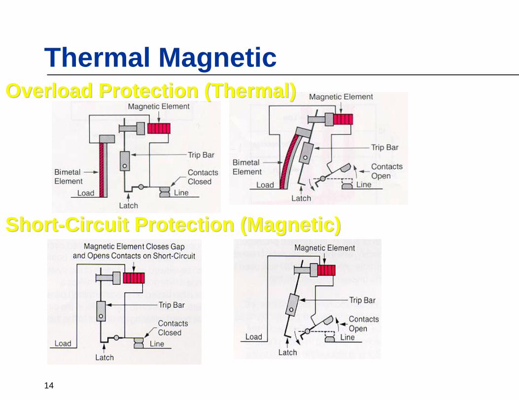
Thermal MagneticOverload Protection (Thermal)Overload Protection (Thermal)
ShortShort--Circuit Protection (Magnetic)Circuit Protection (Magnetic)
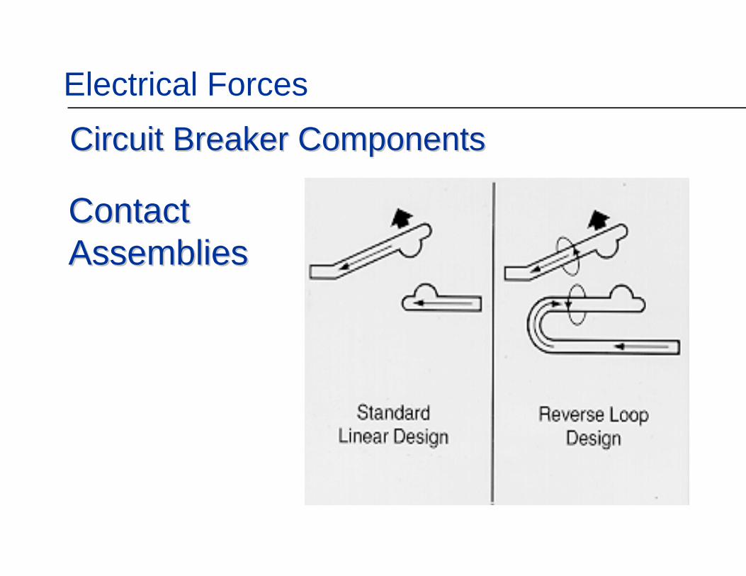
Circuit Breaker ComponentsCircuit Breaker ComponentsElectrical Forces
ContactContactAssembliesAssemblies

16
Know your fault current!
17
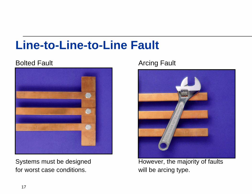
Bolted Fault Arcing Fault
Systems must be designed However, the majority of faultsfor worst case conditions. will be arcing type.
Line-to-Line-to-Line Fault
18
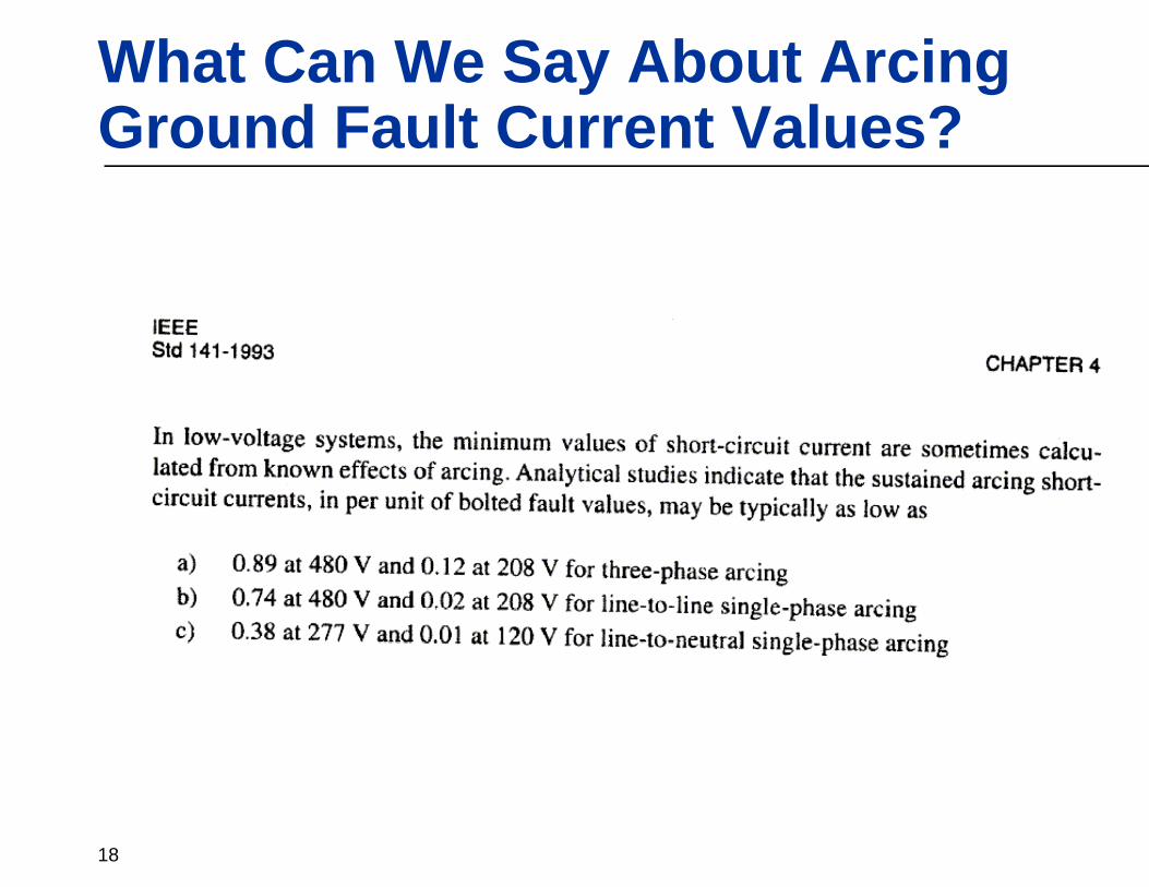
What Can We Say About Arcing Ground Fault Current Values?

19
Why .1 seconds?
“Operating records show that the majority of electric faults originate as phase-to-ground failures.” IEEE std. 141-1993, page 187. (Red book)
“It should be recognized, however, that actual short circuits often involve arcing, and variable arc impedance can reduce low-voltage short-circuit current magnitudes appreciably.” IEEE std. 141-1993, page 113. (Red book)Looking at TCC’s, fault currents that cause operation of OCPD’s in the sub 6 cycle range have been found to be rare occurrences forsystems that have already been safely energized.

20
Does .1 Seconds make Sense -Types and Frequencies of Faults
“Operating records show that the majority of electric faults originate as phase-to-ground failures.” IEEE std. 141-1993, page 187. (Red book)“It should be recognized, however, that actual short circuits often involve arcing, and variable arc impedance can reduce low-voltage short-circuit current magnitudes appreciably.” IEEE std. 141-1993, page 113. (Red book)

21
Molded Case Circuit BreakersMolded Case Circuit Breakers•• Tested in accordance with UL489Tested in accordance with UL489•• Open Air Test Open Air Test -- Rated @ 80%Rated @ 80%•• Over Toggle MechanismOver Toggle Mechanism•• Sealed Case Sealed Case -- Not MaintainableNot Maintainable
•• Applied in Switchboards/PanelboardsApplied in Switchboards/Panelboards
Insulated Case Circuit BreakersInsulated Case Circuit Breakers•• Tested in accordance with UL489Tested in accordance with UL489•• Open Air Test Open Air Test -- Rated @ 80% or 100%Rated @ 80% or 100%•• 22--Step Stored Energy MechanismStep Stored Energy Mechanism•• Sealed Case Sealed Case -- Not Fully MaintainableNot Fully Maintainable•• Applied As Mains in Switchboards/MCC’s Applied As Mains in Switchboards/MCC’s
Power Circuit BreakersPower Circuit Breakers•• Tested in accordance with ANSI C37Tested in accordance with ANSI C37•• Tested in the Enclosure Tested in the Enclosure -- Rated @ 100%Rated @ 100%•• 22--Step Stored Energy MechanismStep Stored Energy Mechanism•• Open Access Open Access -- Fully MaintainableFully Maintainable
•• Applied in MetalApplied in Metal--Enclosed Enclosed DrawoutDrawout Swgr.Swgr.
UL489 versus ANSI C37
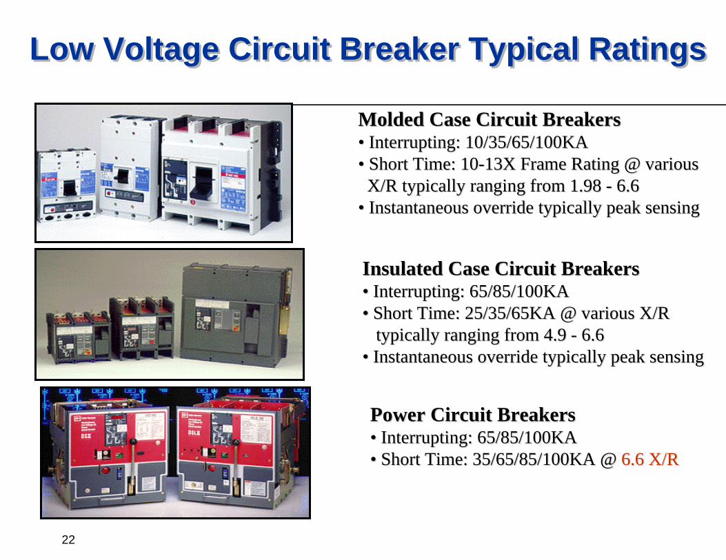
22
Molded Case Circuit BreakersMolded Case Circuit Breakers•• Interrupting: 10/35/65/100KAInterrupting: 10/35/65/100KA•• Short Time: 10Short Time: 10--13X Frame Rating @ various13X Frame Rating @ various
X/R typically ranging from 1.98 X/R typically ranging from 1.98 -- 6.66.6•• Instantaneous override typically peak sensingInstantaneous override typically peak sensing
Insulated Case Circuit BreakersInsulated Case Circuit Breakers•• Interrupting: 65/85/100KAInterrupting: 65/85/100KA•• Short Time: 25/35/65KA @ various X/RShort Time: 25/35/65KA @ various X/R
typically ranging from 4.9 typically ranging from 4.9 -- 6.66.6•• Instantaneous override typically peak sensingInstantaneous override typically peak sensing
Power Circuit BreakersPower Circuit Breakers•• Interrupting: 65/85/100KAInterrupting: 65/85/100KA•• Short Time: 35/65/85/100KA @ Short Time: 35/65/85/100KA @ 6.6 X/R6.6 X/R
Low Voltage Circuit Breaker Typical RatingsLow Voltage Circuit Breaker Typical Ratings
23
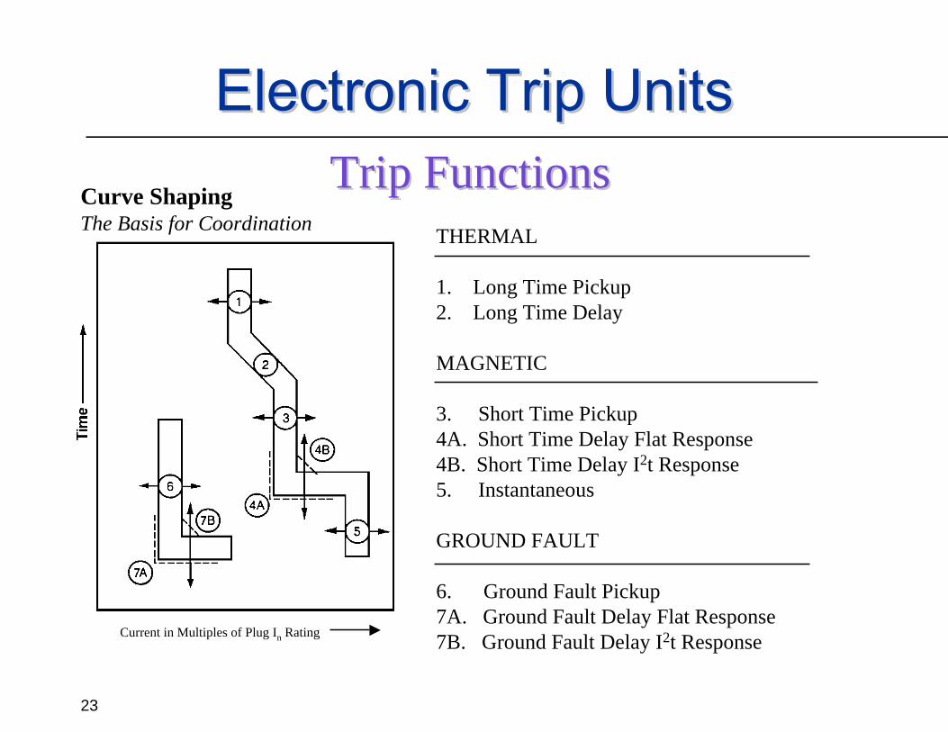
Curve ShapingThe Basis for Coordination THERMAL
1. Long Time Pickup2. Long Time Delay
MAGNETIC
3. Short Time Pickup4A. Short Time Delay Flat Response4B. Short Time Delay I2t Response5. Instantaneous
GROUND FAULT
6. Ground Fault Pickup7A. Ground Fault Delay Flat Response7B. Ground Fault Delay I2t ResponseCurrent in Multiples of Plug In Rating
Electronic Trip UnitsElectronic Trip UnitsTrip FunctionsTrip Functions
24

25

26
Designing Selectively Coordinated Systems
The ability to meet the selective coordination requirements of the NEC is heavily dependent on the system design. In most cases, systems cannot be designed with the same constraints as in the past. Consulting engineers must take into consideration the limitations of fuses and circuit breakers when designing electrical distribution systems where this is a requirement.The larger the frame differences and the fewer emergency devices, the easier to selectively coordinate.

27
Designing SC SystemsLarge Feeders to Small Feeders
MCCB limitations for selective coordination are found in the instantaneous region of the curve.The larger the frame difference, the easier to coordinate.
28
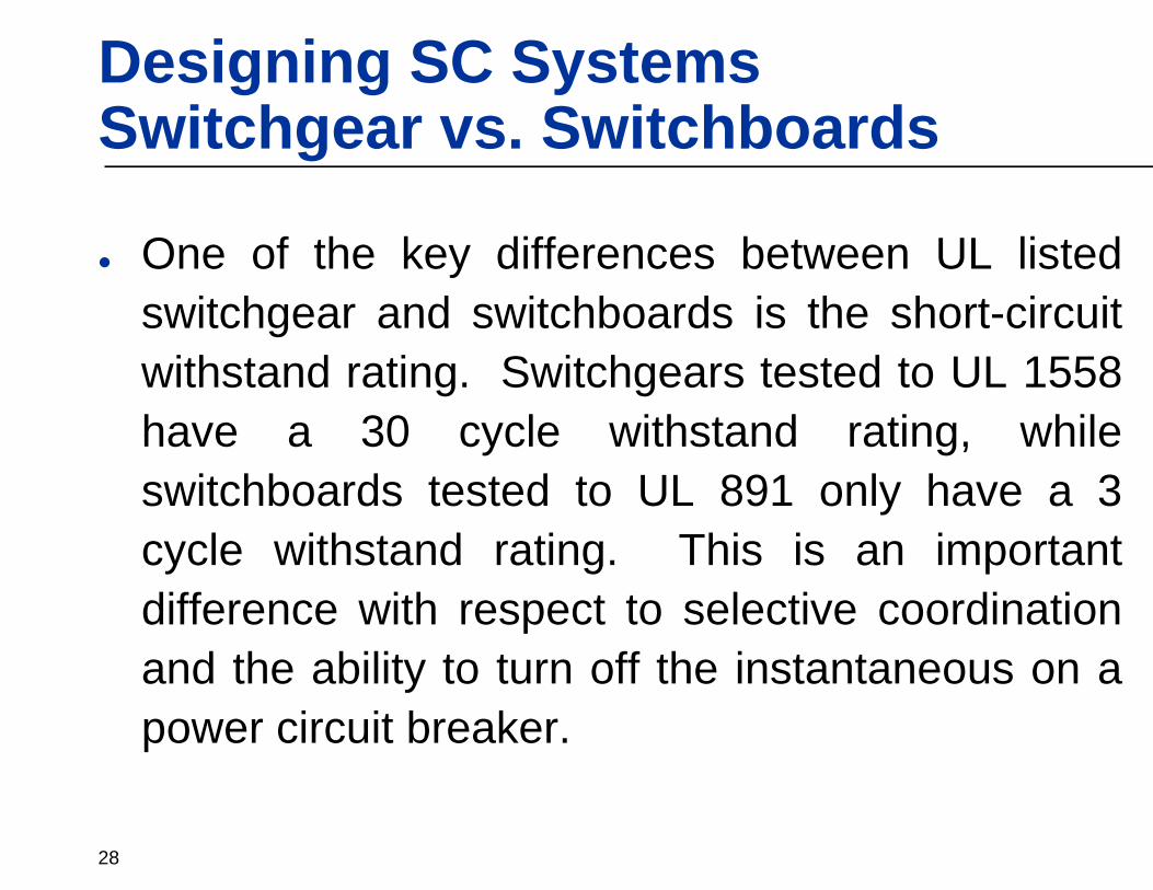
Designing SC SystemsSwitchgear vs. Switchboards
One of the key differences between UL listed switchgear and switchboards is the short-circuit withstand rating. Switchgears tested to UL 1558 have a 30 cycle withstand rating, while switchboards tested to UL 891 only have a 3 cycle withstand rating. This is an important difference with respect to selective coordination and the ability to turn off the instantaneous on a power circuit breaker.

29
Designing SC SystemsSwitchgear vs. Switchboards
Note 2On or OffOn or OffSwitchgear(Tested to UL 1558)
Note 1OnOn or OffSwitchboard(Tested to UL 891)
FeederMain
NotesInstantaneous (3 cycle) Clearing
Equipment Type
Note 1: Disabling the instantaneous function of a switchboard main power circuit breaker is acceptable, as long as the feeder breakers still have an instantaneous function to clear a through-fault downstream of the switchboard within 3 cycles.
Note 2: Disabling the instantaneous function of a switchgear main or feeder power circuit breaker is acceptable, as long as the available fault current does not exceed the 30 cycle short-time rating of the circuit breaker or switchgear.

30
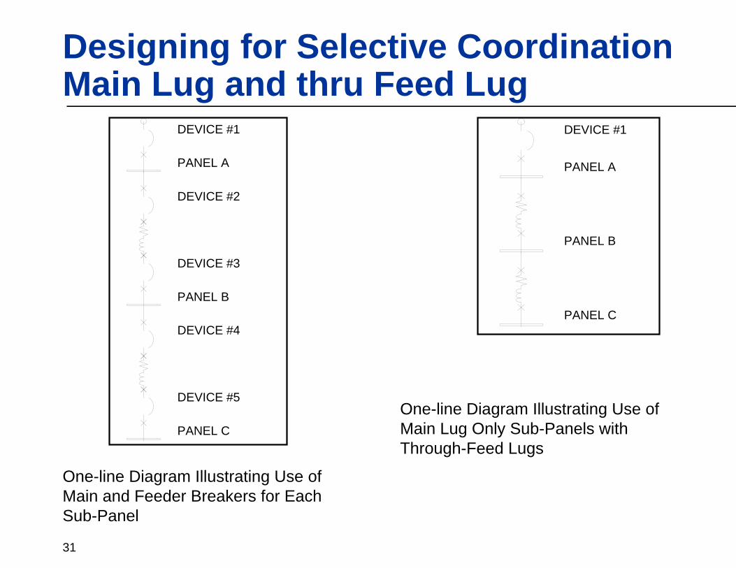
Designing for Selective CoordinationMain Lug and thru Feed Lug
When designing a selectively coordinated system it is important to minimize the number of “levels” of protective devices that need to be coordinated.
31
Designing for Selective CoordinationMain Lug and thru Feed Lug
PANEL A
PANEL B
PANEL C
DEVICE #1
DEVICE #2
DEVICE #3
DEVICE #4
DEVICE #5
PANEL A
PANEL B
PANEL C
DEVICE #1
One-line Diagram Illustrating Use of Main and Feeder Breakers for Each Sub-Panel
One-line Diagram Illustrating Use of Main Lug Only Sub-Panels with Through-Feed Lugs

32
Selective Coordination Discussion – Protective Devices

33
Selective Coordination Discussion – Protective Devices
The amount of Arc Flash Energy resulting in potential equipment damage, possibility of external fires, and hazard to people are dependent on two main factors:1. Actual magnitude of arcing fault current.2. The time it takes the protective device to
open and stop the flow of fault current.
34
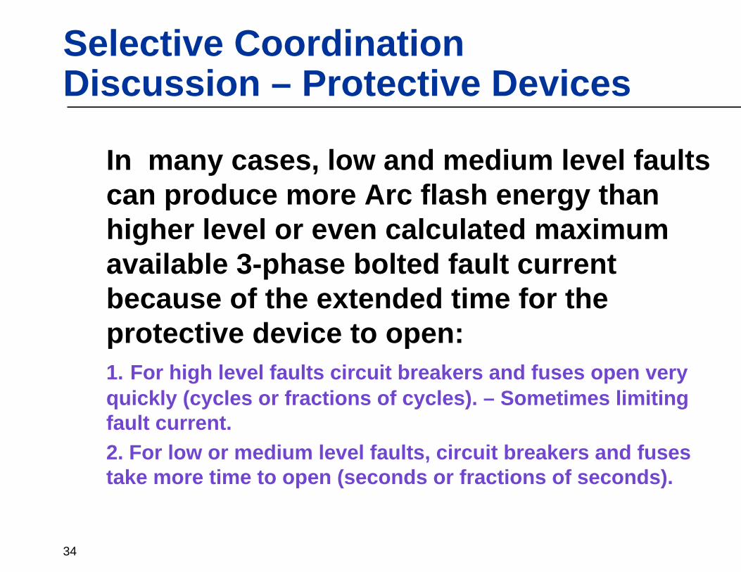
Selective Coordination Discussion – Protective Devices
In many cases, low and medium level faults can produce more Arc flash energy than higher level or even calculated maximum available 3-phase bolted fault current because of the extended time for the protective device to open:1. For high level faults circuit breakers and fuses open very quickly (cycles or fractions of cycles). – Sometimes limiting fault current.2. For low or medium level faults, circuit breakers and fuses take more time to open (seconds or fractions of seconds).

35
Hazard
Risk Category
Clothing Description
(Typical Number of clothing layers given in parenthesis)
Required Minimum
Arc Rating of PPE cal/cm2
0 Non-melting, flammable materials (i.e., untreated cotton, wool, rayon, or silk, or blends of these materials) with a fabric weight
at least 4.5 oz/yd2 (1)
N/A
1 FR shirt and FR pants or FR coverall (1) 4 2 Cotton underwear – conventional short sleeve and brief/shorts,
plus FR shirt and FR pants (1 or 2) 8
3 Cotton underwear plus FR Shirt and FR pants plus FR coverall, or cotton underwear plus two FR coveralls (2 or 3)
25
4 Cotton Underwear plus FR Shirt and FR Pants plus multilayer flash suit (3 or more)
40
Based upon maximum energy for a 2nd degree burn (1.2 cal/cm2)
NFPA 70E-2004: Table 130.7 (C) (11)Protective Clothing Characteristics

36
400A RK1 @ 480V, 3000 AIC
RK1
37
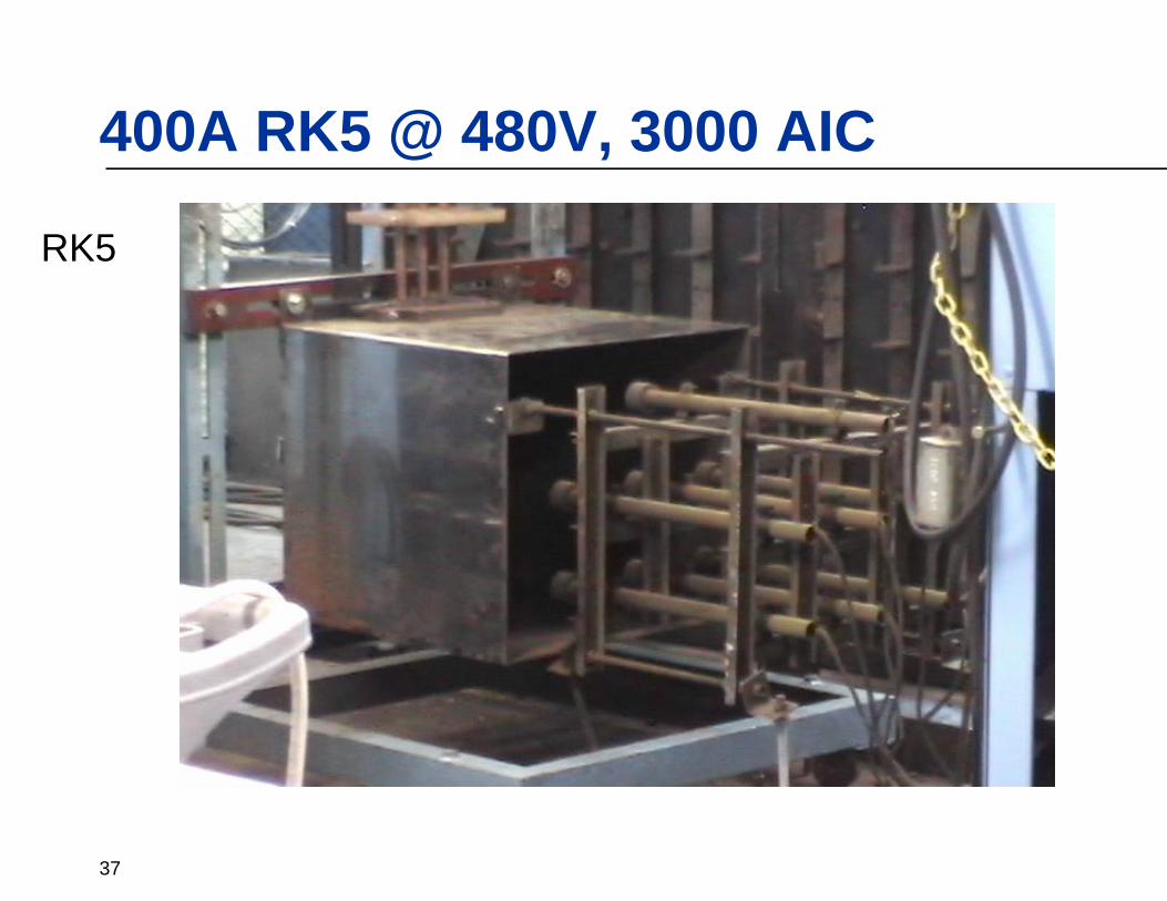
400A RK5 @ 480V, 3000 AIC
RK5

38
400A MCCB @ 480V, 3000 AIC
MCCB
39
Designing SC SystemsATS Ratings
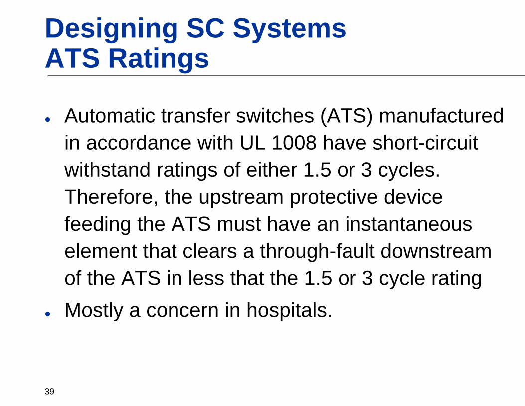
Automatic transfer switches (ATS) manufactured in accordance with UL 1008 have short-circuit withstand ratings of either 1.5 or 3 cycles. Therefore, the upstream protective device feeding the ATS must have an instantaneous element that clears a through-fault downstream of the ATS in less that the 1.5 or 3 cycle rating Mostly a concern in hospitals.
40
Designing SC SystemsATS Ratings
Note 3< 30 cyclesATS w/30 Cycle Withstand
Note 2< 3.0 cyclesATS w/3 Cycle Withstand
Note 1< 1.5 cyclesATS w/1.5 Cycle Withstand
NotesRequired Feeder Protective Device Instantaneous Clearing TimeEquipment Type
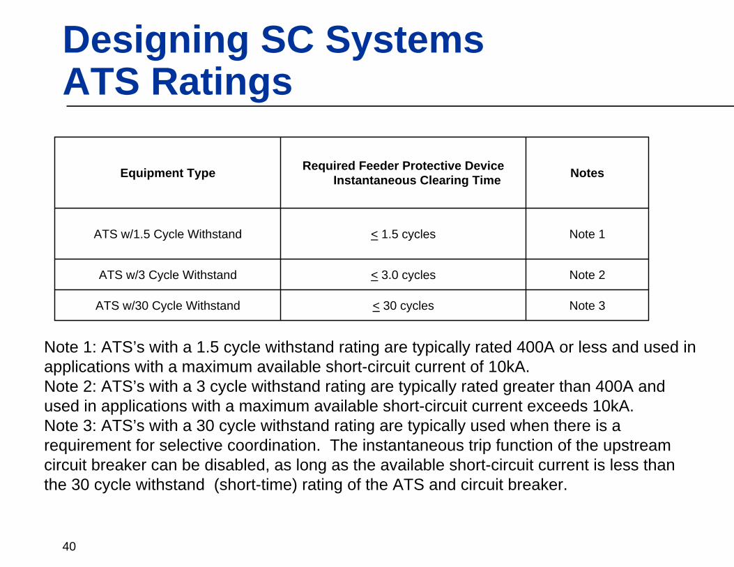
Note 1: ATS’s with a 1.5 cycle withstand rating are typically rated 400A or less and used in applications with a maximum available short-circuit current of 10kA. Note 2: ATS’s with a 3 cycle withstand rating are typically rated greater than 400A and used in applications with a maximum available short-circuit current exceeds 10kA.Note 3: ATS’s with a 30 cycle withstand rating are typically used when there is a requirement for selective coordination. The instantaneous trip function of the upstream circuit breaker can be disabled, as long as the available short-circuit current is less than the 30 cycle withstand (short-time) rating of the ATS and circuit breaker.

41
Designing for Selective CoordinationGenerator Breaker Concerns
Most fuse and circuit breaker manufacturers have performed testing in an effort to develop comprehensive selective coordination tables. However, to date no there has been no cross-manufacturer selective coordination testing performed. This can become an issue when the entire electrical distribution system is comprised of one manufacturer’s equipment, but a different manufacturer provides the generator protective device. In order to avoid this, it is suggested that all protective devices be supplied from the same manufacturer, including the generator protective device.
42
Supplying Selectively Coordinated Systems - Concerns
Generator manufacturer’s typically supply their generators with circuit breakers on the output. To ensure selective coordination, the generator manufacturer may be required to provide a breaker to match the other breakers in the system so that the published selective coordination guide may be used
43
Supplying Selectively Coordinated Systems
The ability to meet the selective coordination requirements of the NEC is heavily dependent on the equipment supplied. In most cases, systems can not be supplied with the same equipment constraints as in the past. Equipment manufacturers must take into consideration the limitations of fuses and circuit breakers when supplying electrical distribution systems where this is a requirement.

44
Supplying Selectively Coordinated Systems
Develop a sound understanding of how the local jurisdiction interprets the NEC selective coordination code with respect to the Zones of Selective Coordination

Thank You for
your Attention!
Now you know the rest of the story…….