self-powered time overcurrent relay wip1 · pdf file6.1.4 parameter setting by using the...
TRANSCRIPT

WIP1 – Self Powered Time Overcurrent Relay
Manual WIP1 (Revision J)

Manual WIP1 Woodward
DOK-TD-WIP1E Rev. J 2
Woodward reserves the right to update any portion of this publication at any time. Information provided by Woodward is believed to be correct and reliable. However, no responsibility is assumed by Woodward unless otherwise expressly
undertaken.
© Woodward 1994-2017

Manual WIP1 Woodward
DOK-TD-WIP1E Rev. J 3
Contents
1. Comments on the Manual ........................................................................................ 5 1.1 Information Concerning Liability and Warranty.................................................................................. 5 1.2 IMPORTANT DEFINITIONS .............................................................................................................. 6
2. General ...................................................................................................................... 7
3. Characteristics and Features ................................................................................... 8
4. Design ........................................................................................................................ 9 4.1 Connections ....................................................................................................................................... 9
4.1.1 Connecting the Serial Interface ................................................................................................... 13 4.1.2 Current Transformer Inputs ......................................................................................................... 14 4.1.3 Control Inputs............................................................................................................................... 14 4.1.4 Operation Outputs ....................................................................................................................... 15 4.1.5 Trip Indication .............................................................................................................................. 16 4.1.6 Serial Interface ............................................................................................................................. 16
5. Working Principle ................................................................................................... 17 5.1 Current Transformer Inputs ............................................................................................................. 17 5.2 Digital Circuits .................................................................................................................................. 17 5.3 Relay Clock for Timestamps ............................................................................................................ 17 5.4 Operating Modes ............................................................................................................................. 18
5.4.1 Phase Current ≥ 0.5 A (CT-Powered Mode) ............................................................................... 18 5.4.2 Phase Current < approx. 0.35 A (Offline Mode) .......................................................................... 18 5.4.3 Dual Power Option for WIP1-2 and WIP1-3 ................................................................................ 18
5.5 Indicating and Operating Elements ................................................................................................. 19 5.5.1 Front Plate ................................................................................................................................... 19 5.5.2 Display ......................................................................................................................................... 19 5.5.3 LED .............................................................................................................................................. 19
5.6 Function Push Buttons ..................................................................................................................... 19 5.7 Requirements for the Main C.T.s ..................................................................................................... 20
5.7.1 Determining the Maximum Coil Resistance ................................................................................. 20 5.7.2 Characteristics of the Current Transformers ............................................................................... 21 5.7.3 Overloading of the WIP1 .............................................................................................................. 23 5.7.4 Dimensioning Example ................................................................................................................ 24
6. Operations and Settings ........................................................................................ 26 6.1 Function of Push Buttons ................................................................................................................. 27
6.1.1 Measuring Value and Fault Indication ......................................................................................... 27 6.1.2 Display ......................................................................................................................................... 28 6.1.3 Setting Procedure ........................................................................................................................ 28 6.1.4 Parameter setting by using the password ................................................................................... 28
6.2 Display of Measuring Values ........................................................................................................... 29 6.3 Displaying the Pickup Phase ........................................................................................................... 30 6.4 Display of Tripping Values ............................................................................................................... 30 6.5 Protection parameters ..................................................................................................................... 32
6.5.1 Pickup Value for Phase Overcurrent Element ............................................................................. 32 6.5.2 Time Current Characteristics for Phase Overcurrent Element .................................................... 32 6.5.3 Trip Delay or Time Multiplier for Phase Overcurrent Element ..................................................... 32 6.5.4 Reset Mode for Inverse Time Tripping Characteristics for Phase Overcurrent Element ............ 33 6.5.5 Minimal Time ................................................................................................................................ 33 6.5.6 Current setting for High Set Element ........................................................................................... 33 6.5.7 Trip Delay for High Set Element .................................................................................................. 33 6.5.8 Pickup Value for Earth Fault Current Element ............................................................................. 34 6.5.9 Tripping Characteristic for Earth Fault Current Element.............................................................. 34 6.5.10 Trip delay or Time Multiplier for Earth Fault Overcurrent Element .......................................... 34 6.5.11 Reset Mode for Normal Inverse Time Tripping Characteristics for Earth Fault Element ........ 34 6.5.12 Minimum Tripping Time (Earth Fault Element) ........................................................................ 34 6.5.13 Current Setting for Earth Fault High Set Element .................................................................... 34 6.5.14 Trip Delay for Earth Fault High Set Element ........................................................................... 34
6.6 System Parameters ......................................................................................................................... 35
Manual WIP1 Woodward
DOK-TD-WIP1E Rev. J 4
6.6.1 Selection of the Language ........................................................................................................... 35 6.6.2 Password Programming .............................................................................................................. 35 6.6.3 Date Setting ................................................................................................................................. 36 6.6.4 Time Setting ................................................................................................................................. 36 6.6.5 Rated Frequency Setting ............................................................................................................. 36 6.6.6 Setting of the Communication Slave Address (only WIP1-3) ...................................................... 36 6.6.7 Baud Rate Setting (only WI1-3) ................................................................................................... 36 6.6.8 Setting of Parity (only WIP1-3) .................................................................................................... 37 6.6.9 Indication of the Software Version ............................................................................................... 37
6.7 Tripping Method/Relay Matrix .......................................................................................................... 37 6.7.1 Reset ............................................................................................................................................ 37 6.7.2 Tripping method ........................................................................................................................... 37 6.7.3 Earth Fault Overcurrent ............................................................................................................... 38 6.7.4 Flashing of the Trip-LED .............................................................................................................. 38 6.7.5 Relay matrix (only relay 2) ........................................................................................................... 38
6.8 Signal Inputs .................................................................................................................................... 39 6.8.1 Fast Trip ....................................................................................................................................... 39 6.8.2 Blocking the Protection Functions ............................................................................................... 39
6.9 Reset ................................................................................................................................................ 39 6.10 Clearing the Fault Memory .............................................................................................................. 40
7. Relay Testing and Commissioning ....................................................................... 41 7.1 Checking the Set Values ................................................................................................................. 41 7.2 Secondary Injection Test ................................................................................................................. 41
7.2.1 Test Equipment ............................................................................................................................ 41 7.2.2 Example of Test Circuit ................................................................................................................ 42 7.2.3 Checking the Tripping Circuits ..................................................................................................... 43 7.2.4 Checking the Input Circuits and Measured Values...................................................................... 45 7.2.5 Checking the Overcurrent Element ............................................................................................. 45 7.2.6 Checking the High Set Element of the Relay .............................................................................. 45 7.2.7 Checking the External Blocking ................................................................................................... 46 7.2.8 Checking the Input “Fast Trip” ..................................................................................................... 46 7.2.9 Remote Trip ................................................................................................................................. 46 7.2.10 Test of Input „External Reset“ .................................................................................................. 46
7.3 Primary Injection Test ...................................................................................................................... 46 7.4 Benefits from Using the Display Battery .......................................................................................... 47
8. Maintenance ............................................................................................................ 48 8.1 Opening the Front Cover ................................................................................................................. 48 8.2 Display Battery ................................................................................................................................. 49
8.2.1 Checking the Battery ................................................................................................................... 49 8.2.2 Changing the Battery ................................................................................................................... 49
9. Technical Data......................................................................................................... 52 9.1 System Data .................................................................................................................................... 54 9.2 Setting Ranges and Steps ............................................................................................................... 55 9.3 Inverse Time Tripping Characteristics ............................................................................................. 56
9.3.1 Tripping Characteristics ............................................................................................................... 58 9.4 Relay Case ...................................................................................................................................... 65 9.5 Flag Indicators ................................................................................................................................. 66
10. FAQ (Frequently Asked Questions) ...................................................................... 67
11. Order Form .............................................................................................................. 69

Manual WIP1 Woodward
DOK-TD-WIP1E Rev. J 5
1. Comments on the Manual This manual explains in general the tasks of device planning, parameter setting, installation, commissioning, operation and maintenance of the WIP1 device. The manual serves as working basis for the following user types:
engineers in the protection field,
commissioning engineers,
people dealing with setting, testing and maintenance of protection and control devices,
trained personnel for electrical installations and power stations. All functions concerning the type code will be defined. Should there be a description of any functions, pa-rameters or inputs/outputs which do not apply to the device in use, please ignore that information. All details and references are explained to the best of our knowledge and are based on our experience and observations. This manual describes the (optionally) full featured versions of the devices. All technical information and data included in this manual reflect their state at the time this document was is-sued. We reserve the right to carry out technical modifications in line with further development without changing this manual and without previous notice. Hence no claim can be brought based on the information and descriptions this manual includes. Text, graphic and formulae do not always apply to the actual delivery scope. The drawings and graphics are not true to scale. We do not accept any liability for damage and operational failures caused by operating er-rors or disregarding the directions of this manual. No part of this manual is allowed to be reproduced or passed on to others in any form, unless Woodward Kempen GmbH have approved in writing. This user manual is part of the delivery scope when purchasing the device. In case the device is passed on (sold) to a third party, the manual has to be handed over as well. Any repair work carried out on the device requires skilled and competent personnel who need to be well aware especially of the local safety regulations and have the necessary experience for working on electronic protection devices and power installations (provided by evidence).
1.1 Information Concerning Liability and Warranty
Woodward Kempen GmbH does not accept any liability for damage resulting from conversions or changes carried out on the device or planning (projecting) work, parameter setting or adjustment changes done by the customer. The warranty expires after a device has been opened by others than Woodward Kempen GmbH specialists. Warranty and liability conditions stated in Woodward Kempen GmbH General Terms and Conditions are not supplemented by the above mentioned explanations.
Manual WIP1 Woodward
DOK-TD-WIP1E Rev. J 6
1.2 IMPORTANT DEFINITIONS
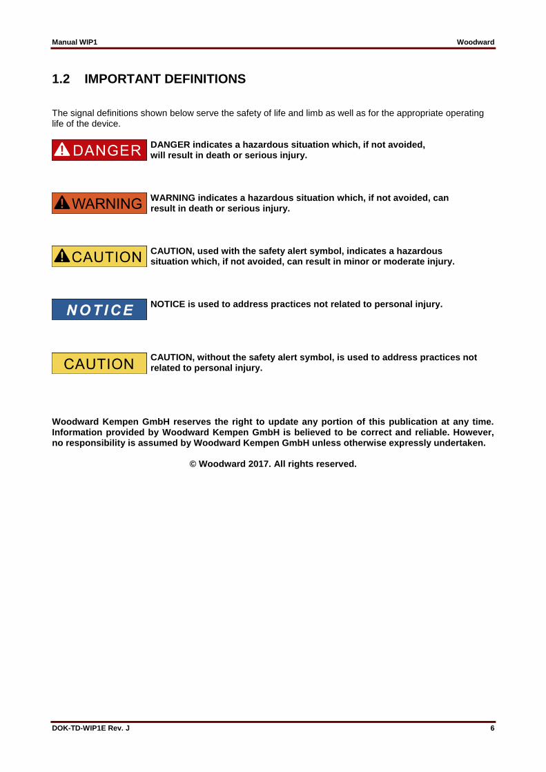
The signal definitions shown below serve the safety of life and limb as well as for the appropriate operating life of the device.
DANGER indicates a hazardous situation which, if not avoided, will result in death or serious injury.
WARNING indicates a hazardous situation which, if not avoided, can result in death or serious injury.
CAUTION, used with the safety alert symbol, indicates a hazardous situation which, if not avoided, can result in minor or moderate injury.
NOTICE is used to address practices not related to personal injury.
CAUTION, without the safety alert symbol, is used to address practices not related to personal injury.
Woodward Kempen GmbH reserves the right to update any portion of this publication at any time. Information provided by Woodward Kempen GmbH is believed to be correct and reliable. However, no responsibility is assumed by Woodward Kempen GmbH unless otherwise expressly undertaken.
© Woodward 2017. All rights reserved.

Manual WIP1 Woodward
DOK-TD-WIP1E Rev. J 7
2. General The WIP1 is a self-powered time overcurrent relay with multi-characteristics and including earth fault protec-tion. Definite time and inverse time tripping characteristics can be selected. Due to its wide setting ranges, the tripping characteristic can be selected to protect a wide variety of different equipment. The WIP1 does not require any aux. voltage supply, consequently it can also be used for switchboards with-out auxiliary power supply. It takes its power supply energy from the C.T. circuits and provides the tripping pulse energy to the circuit breaker. The WIP1 is a robust protective device that is designed for a long-time operation with minimum maintenance efforts even under extreme climate conditions. Our experience with WI Line self-powered protective relays shows that the MTBF („Mean Time Between Failures“) is approx. 200 years (calculated based on data up to year 2012), and there are WIP1 relays being in service at our customers’ sites for more than 22 years even under harsh climate conditions.

Manual WIP1 Woodward
DOK-TD-WIP1E Rev. J 8
3. Characteristics and Features
Auxiliary voltage supply is not required
User-friendly setting procedure with wide setting ranges
Protective Elements will use DFT signals (50/60 Hz Signals) only. Digital filtering of measured quan-tities by using discrete Fourier analysis to suppress high frequency harmonics and transient DC components induced by faults or system operations
2.nd harmonics filtering (Inrush)
Two-element overcurrent and short circuit relay
Selectable protection functions between: - definite time overcurrent and - inverse time overcurrent
Selectable inverse time characteristics acc. to IEC 255-4: - normal inverse (type A) - very inverse (type B) - extremely inverse (type C) - special characteristics
Earth fault protection with 2 stages (IE>, IE>>)
Reset mode for inverse time characteristics selectable
High-set overcurrent element with instantaneous or definite time function
Two-stage earth fault supervision with tripping and/or alarm function
Redundant power supply unit for external voltage supply (Option WIP1-2)
Serial interface for connection to SCADA Systems (Option WIP1-3)
Phase and earth current measuring during normal operation
Fault values can be shown on the display.
Fault values are stored within the relay together with a timestamp.
Five fault memories
High-accuracy components and over-rating guarantee precision, reliability and a long service life
High operating reliability through internal self-supervision (watchdog); internal faults are indicated by an alarm relay
Remote tripping via external voltage
High-capacity electric pulse output for direct triggering the circuit breaker
Trip indication via external flag indicator with mechanical reset
Two potential free alarm contacts, latched type (bi-stable relay)
Relay with one potential free contact; tripping function selectable
Trip value indication via LCD display, battery-buffered
Compact construction
Insensitive to extreme environmental conditions
In accordance with the specified technical data, it complies with the requirement of VDE regulation 0435-303, IEC255, VDE 0843
Manual WIP1 Woodward
DOK-TD-WIP1E Rev. J 9
4. Design
4.1 Connections
fast trip
WIP
_Z0
3
signal relay impulstripping out
trippingremote
supplypower
serial interfaceRS485
supervisionself trip relay
reset
reserve
blocking input
L1 L2 L3
S1S2S3
S1S2S3
S1S2S3
1S1
1S2
2S1
2S2
3S1
3S2
1E1
1E2
32 33 23 24 25 26 27 28 11 12 1 2 1E1 1E2 1S1 2S1 3S1 1S2 2S2 3S2 20 22
A1 A2 J1 P N J2 29 30 31 34 35 36 14 15 16 17
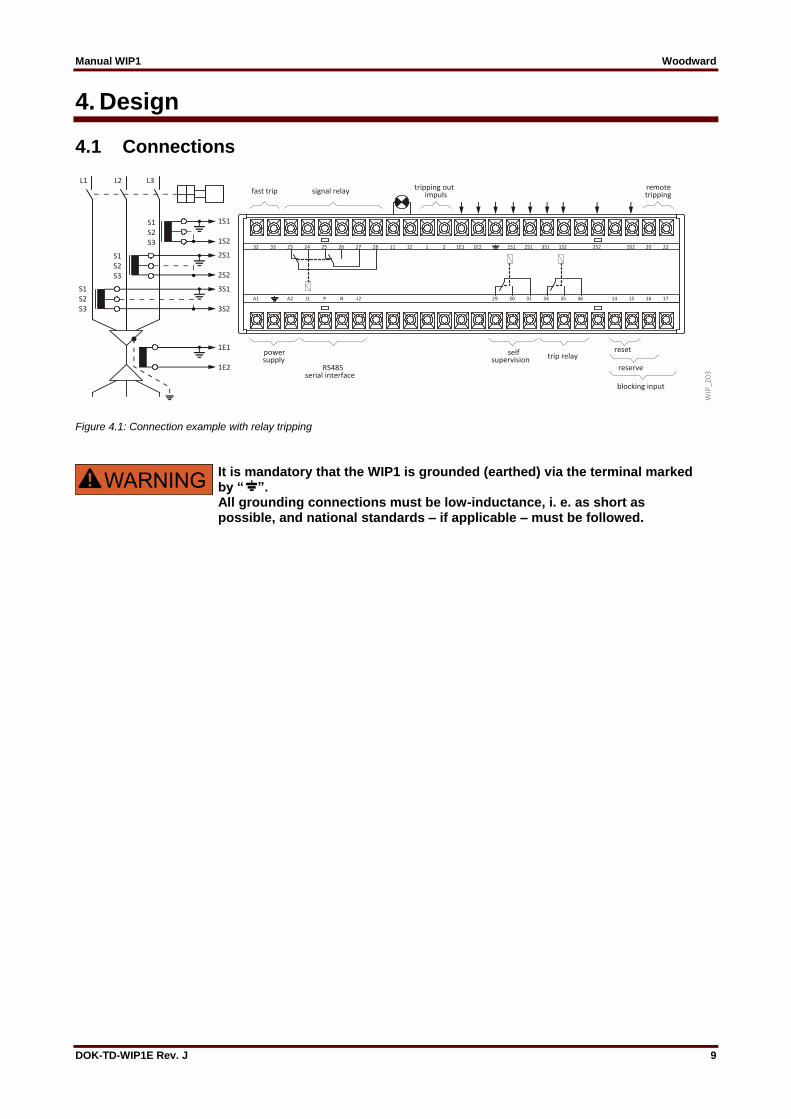
Figure 4.1: Connection example with relay tripping
It is mandatory that the WIP1 is grounded (earthed) via the terminal marked by “ ”. All grounding connections must be low-inductance, i. e. as short as possible, and national standards – if applicable – must be followed.
Manual WIP1 Woodward
DOK-TD-WIP1E Rev. J 10
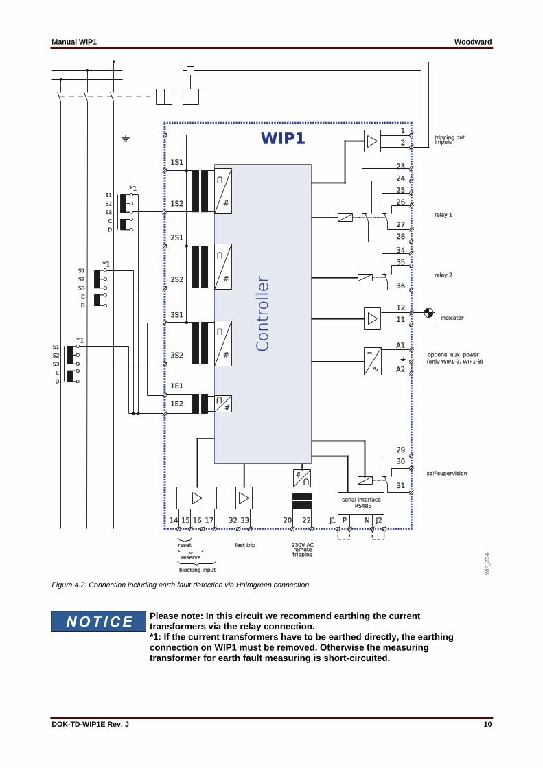
Figure 4.2: Connection including earth fault detection via Holmgreen connection
Please note: In this circuit we recommend earthing the current transformers via the relay connection. *1: If the current transformers have to be earthed directly, the earthing connection on WIP1 must be removed. Otherwise the measuring transformer for earth fault measuring is short-circuited.
Manual WIP1 Woodward
DOK-TD-WIP1E Rev. J 11
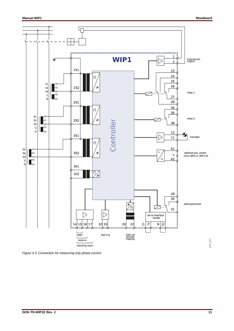
Figure 4.3: Connection for measuring only phase current

Manual WIP1 Woodward
DOK-TD-WIP1E Rev. J 12
Figure 4.4: Connection including earth fault detection via C.T. cable type
Manual WIP1 Woodward
DOK-TD-WIP1E Rev. J 13
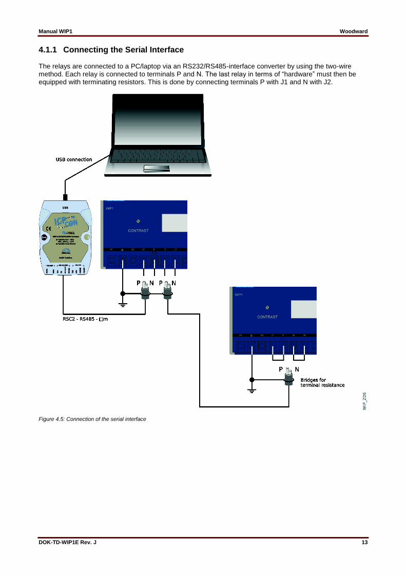
4.1.1 Connecting the Serial Interface The relays are connected to a PC/laptop via an RS232/RS485-interface converter by using the two-wire method. Each relay is connected to terminals P and N. The last relay in terms of “hardware” must then be equipped with terminating resistors. This is done by connecting terminals P with J1 and N with J2.
Figure 4.5: Connection of the serial interface
Manual WIP1 Woodward
DOK-TD-WIP1E Rev. J 14
4.1.2 Current Transformer Inputs The protection unit WIP1 receives the analog input signals of the phase currents IL1 (1S1 ‑ 1S2),
IL2 (2S1 ‑ 2S2) and IL3 (3S1 ‑ 3S2) for phase current, earth current and negative sequence measuring.
The measured current values are analogously filtered and fed to the analog/digital converter.
4.1.3 Control Inputs Input remote tripping The remote tripping input (terminals 20 and 22) enables tripping by an external voltage pulse, e. g. from a thermal overcurrent tripping device, Buchholz protection or other external trip commands. By bypassing the measuring circuits, this input (230 V AC max. 5 min) has a direct effect on the trip circuit. The input terminals are galvanically decoupled from the relay electronics. Signal inputs Signal inputs for blocking and protection (terminals 14 and 17) for fast trip (terminals 32 and 33) as well as external reset (terminals 14 and 15) can be activated by applying an external voltage. (Voltage level: see “Signal inputs” in Chapter 9.) Blocking function (terminals 14 and 17): Single or all trip elements can either be blocked or re-leased. Fast trip (terminals 32 and 33): By this function the CB can be tripped instantaneously. There are two different kind of trippings:
Instantaneous means, a trip is initiated as soon as the minimum current is available (lowest power supply value adjustable).
After activation means, the high-speed tripping function only is activated if one of the phase currents exceeds the set value.
The fast trip input can be applied for e.g. arcing fault detectors. Reset After a trip event the alarm relay is reset and the LED extinguishes when voltage is applied (see also chapter 6.9 “Reset”. For the voltage level: see “Signal inputs” in Chapter 9).
Manual WIP1 Woodward
DOK-TD-WIP1E Rev. J 15
4.1.4 Operation Outputs There is the choice of two tripping methods:
Electric pulse output A trip command is a sequence of power pulses that the WIP1 gives directly to the tripping coil of the CB (terminals 1 and 2). These pulses are given every 150 ms and repeated until the CB is switched off. (See also “Electro pulse output circuit” in Chapter “Technical Data”.)
Potential free contacts (relay 1/latching) terminals (23, 24, 28 and 24, 25, 26) For applications where a higher trip output energy is required, a bi-stable relay with two potential free changeover contacts is provided in the trip circuit. After the relay has tripped, the contacts remain in trip position until reset by the <RESET> push button.
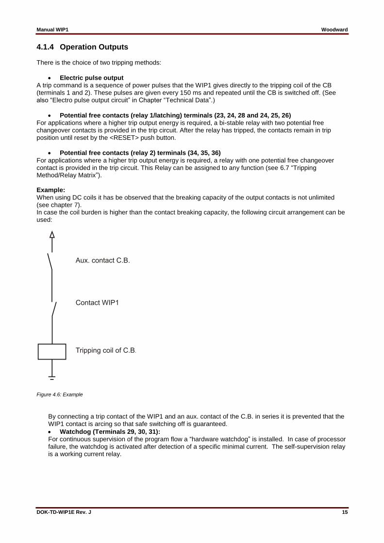
Potential free contacts (relay 2) terminals (34, 35, 36) For applications where a higher trip output energy is required, a relay with one potential free changeover contact is provided in the trip circuit. This Relay can be assigned to any function (see 6.7 “Tripping Method/Relay Matrix”). Example: When using DC coils it has be observed that the breaking capacity of the output contacts is not unlimited (see chapter 7). In case the coil burden is higher than the contact breaking capacity, the following circuit arrangement can be used:
Figure 4.6: Example
By connecting a trip contact of the WIP1 and an aux. contact of the C.B. in series it is prevented that the WIP1 contact is arcing so that safe switching off is guaranteed.
Watchdog (Terminals 29, 30, 31): For continuous supervision of the program flow a “hardware watchdog” is installed. In case of processor failure, the watchdog is activated after detection of a specific minimal current. The self-supervision relay is a working current relay.

Manual WIP1 Woodward
DOK-TD-WIP1E Rev. J 16
4.1.5 Trip Indication The WIP1 is provided with an LED for the optical trip indication. Tripping can additionally be indicated via an external indicator. Flashing of the LED can be suppressed by parameter setting. Fault values can be shown on the display, and moreover, the fault values are stored within the relay together with a timestamp.
4.1.6 Serial Interface By way of hardware the serial interface is a RS-485 interface. The WIP1-3 relay can alternatively be pro-vided with either Modbus Protocol or Woodward-Pro Open Data Protocol. For protocol data please see the Profi-Pack file for Modbus or the Woodward-Pro Open Data Protocol.
Manual WIP1 Woodward
DOK-TD-WIP1E Rev. J 17
5. Working Principle
5.1 Current Transformer Inputs The alternating currents induced by the main current transformers provide the WIP1's supply energy and form the measuring value. The measuring currents are galvanically isolated via the input transformers, decoupled from high-frequency interferences by analog RC-filters and then converted into current proportional voltages. The noise signals caused by inductive and capacitive coupling are suppressed by an analog R-C filter circuit. The analog voltage signals are fed to the A/D-converter of the microprocessor and transformed to digital signals through Sample-and-Hold-circuits. The analog signals are sampled at 50 Hz (60 Hz) with a sampling frequency of 800 Hz (960 Hz), namely, a sampling rate of 1.25 ms (1.04 ms) for every measuring quantity. (16 samples per period).
5.2 Digital Circuits The essential part of the WIP1 is a powerful microcontroller. All of the operations - from the analogue/digital conversion to the relay trip decision - are carried out by the microcontroller digitally. The relay program is saved in an EPROM (Electrically-Programmable-Read-Only-Memory). With this program the CPU of the microcontroller processes the voltages applied at the analogue input circuits and calculates the basic current harmonics. For this calculation an efficient digital filter, based on the Fourier Transformation (DFT – Discrete Fourier Transformation) is applied to suppress high frequency harmonics and DC components caused by fault-induced transients or other system disturbances. The relay setting values for all parameters are saved in a parameter memory (EEPROM - Electrically Erasable Programmable Read-only Memory) and constantly compared with the actual current by the microprocessor. If a phase current exceeds the pickup value, an alarm is given and after the set trip delay has elapsed, the corresponding trip relay is activated. For continuous supervision of the program flow a “hardware watchdog” is installed. In case of failure, the watchdog timer resets the microprocessor and gives an alarm signal via the “self-supervision” output relay. Such a failure is indicated by the following display:
_Internal_Fault__ ________________
5.3 Relay Clock for Timestamps The relay is provided with a buffered clock so that the system time is kept even the power supply is interrupted. (All protection functions remain fully functional even if the battery is empty or not fitted at all.)

Manual WIP1 Woodward
DOK-TD-WIP1E Rev. J 18
5.4 Operating Modes
5.4.1 Phase Current ≥ 0.5 A (CT-Powered Mode) The WIP1 is already fully operational – including all protection functions and a permanent display of measurement values (see 6.2) – as soon as the CT current is ≥ 0.5 A in at least one phase. (This is also the smallest possible setting for the tripping threshold.) Dual-power (which is an option only for WIP1-2 and WIP1-3) reduces this even further, see 5.4.3. Note that some functionality is already available below 0.5 A (for exact data see 9.2). In particular, the automatic reset has to be mentioned here from the user’s point of view. (See description in Chapter 6.9 “Reset”.)
5.4.2 Phase Current < approx. 0.35 A (Offline Mode) Without any power supply (if there is no dual-power and the phase current is not sufficient to enter the CT-powered mode) the WIP1 can be activated by pressing the <DISPLAY ON> button. (The display is then powered by the display battery.)
The WIP1 normally shows the menu for parameter settings. This allows for configuring the relay “offline”, i. e. without having it connected to the substation.
However, if the WIP1 had tripped and therefore switched off its power supply via the CTs, then it shows the Fault Memory menu after pressing the <DISPLAY ON> button.
See Figure 6.1 for an overview of the menu structure.
Note the following for WIP1-1 and WIP1-2/3 without dual-power option: If the maximum phase current is between approx. 0.35 A and 0.5 A it can happen that after pressing the <DISPLAY ON> button the WIP1 tries to enter the CT-Powered Mode although the power supply is not sufficient for this. One can recognize this activity by the fact that the display shows nothing but a “–” character. In this case entering the offline mode is only possible after the CT current has been reduced below approx. 0.3 A (e. g. by simply disconnecting the WIP1).
5.4.3 Dual Power Option for WIP1-2 and WIP1-3 The relay versions WIP1-2 and WIP1-3 offer a dual power option, i. e. the option to connect an additional external power supply. The dual power source makes the relay operational independently of the supply via the CTs. Moreover, there is an extended setting range for the phase overcurrent protection, the lowest possible pickup threshold is 0.2 A. The dual-power will make the relay n-1 secure, because the electrical power that the relay requires for operation is taken either from the dual power source or from the CTs.

Manual WIP1 Woodward
DOK-TD-WIP1E Rev. J 19
5.5 Indicating and Operating Elements
5.5.1 Front Plate There are the following indicating and operating elements at the front of the relay:
Two-line LC display with 16 characters per line
Push buttons for adjustment and operation
LED for trip indication
5.5.2 Display All setting and measuring values as well as fault data are shown in the LC display.
5.5.3 LED The trip status is indicated by the LED at the front. If the relay has tripped, the LED flashes and can be switched off by pressing any push button. Refer to chapters 6.7.4 and 6.9.
5.6 Function Push Buttons The following four function push buttons are arranged at the front of the relay: <SELECT/RESET> “Select” = Selection of function displayed (short pressing of the push button) “Reset” = Reset of trip functions (long pressing of the push button, for 3 s) <+> and <-> Selection of parameters <ENTER> Storing parameters <DISPLAY ON> Switching the relay on. If no key is pressed longer than 1 min. the relay switches off. The push buttons <SELECT/RESET>, <+>, <-> and <DISPLAY ON> can be activated without removing the transparent cover by simply using a pin or screw driver.
Figure 5.1: Front plate of WIP1

Manual WIP1 Woodward
DOK-TD-WIP1E Rev. J 20
5.7 Requirements for the Main C.T.s The advantage of self-powered overcurrent relays is that they do not need any auxiliary power supply. This results from the fact that the overcurrent relay and the tripping unit receive their energy from the main C.T.s. The tripping principle of the WIP1 is that the transformer current is driven through the tripping coil in case tripping takes place. Care must be taken that the current transformer can transmit enough energy at the set overcurrent pickup value to activate the tripping coil, but does not generate too much energy at high short circuit currents which would damage the overcurrent relay. The tripping coil and current transformer have to be determined as follows. First of all it must be established how much force is required to cause the C.B. to trip. This force must be converted to electric energy. It can also be established by measurement. This value is very important. Many coils are defined by way of their rated data such as rated voltage, rated current, internal resistance and/or permissible on-period. These data do not permit any conclusions regarding the usability of a coil as the tripping capacity with rated data is usually much higher than is necessary for safe tripping.
5.7.1 Determining the Maximum Coil Resistance
Figure 5.2: Tripping via current transformer I < 12 x In
Figure 5.3: Tripping via self-supply as from 12 x In

Manual WIP1 Woodward
DOK-TD-WIP1E Rev. J 21
The two diagrams above show the two different tripping methods. In Figure 5.2 the tripping coil is supplied directly by the current transformer. In Figure 5.3 tripping is effected via an internal supply transformer. The result is that with tripping current > 12 x In the coil resistance must not be smaller than 17 Ohm. Once it has been established that the tripping current is smaller than 12 x In, the minimum possible coil resistance can be derived from Figure 5.4.
Figure 5.4: Minimum coil resistance
5.7.2 Characteristics of the Current Transformers
Figure 5.5: Circuit diagram of the secondary C.T. side and magnetizing curve
During normal operation the load of the current transformer is only the WIP impedance and the impedances of the connection cables. In case of tripping, the tripping coil also affects the transformer. Under any circumstances it must be prevented that this load has the effect that the transformer gets into saturation to such an extent that the current flowing through the coil becomes too low to ensure definite tripping. The secondary transformer current Isec is proportional to the primary transformer current and is a function of the transformation ratio. This current is divided into the magnetization current of the transformer and a current IL which flows through the current paths of the overcurrent protection system. The flux Ф is proportional to the voltage UL and linked to the magnetization current Iµ via the magnetization curve. As from the value Фs the transformer moves into saturation. As a result the magnetization current grows overproportionally and the load current decreases at the same rate. So when the transformers are dimensioned it must be taken into account that with a known resistance ZL the current IL is still sufficient for tripping the coil. For this reason, the rated current of the tripping coil must be inserted for ISp in the calculation below. As the coil current ISp is a direct current, it must be converted into an effective AC value by means of eq. 1 or eq. 2 (see below). The result is, at the same time, the lowest switching point for possible tripping.
Manual WIP1 Woodward
DOK-TD-WIP1E Rev. J 22
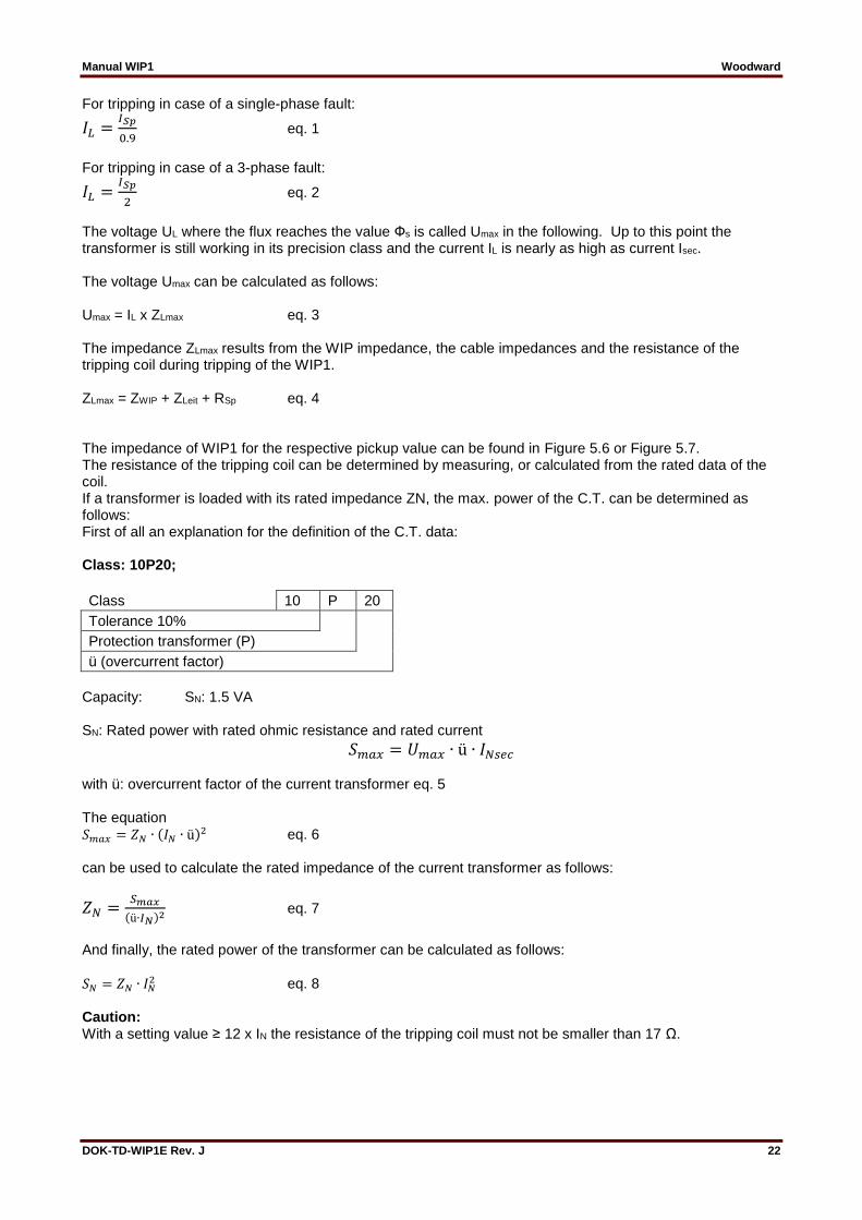
For tripping in case of a single-phase fault:
𝐼𝐿 =𝐼𝑆𝑝
0.9 eq. 1
For tripping in case of a 3-phase fault:
𝐼𝐿 =𝐼𝑆𝑝
2 eq. 2
The voltage UL where the flux reaches the value Фs is called Umax in the following. Up to this point the transformer is still working in its precision class and the current IL is nearly as high as current Isec. The voltage Umax can be calculated as follows: Umax = IL x ZLmax eq. 3 The impedance ZLmax results from the WIP impedance, the cable impedances and the resistance of the tripping coil during tripping of the WIP1. ZLmax = ZWIP + ZLeit + RSp eq. 4 The impedance of WIP1 for the respective pickup value can be found in Figure 5.6 or Figure 5.7. The resistance of the tripping coil can be determined by measuring, or calculated from the rated data of the coil. If a transformer is loaded with its rated impedance ZN, the max. power of the C.T. can be determined as follows: First of all an explanation for the definition of the C.T. data: Class: 10P20;
Class 10 P 20
Tolerance 10%
Protection transformer (P)
ü (overcurrent factor)
Capacity: SN: 1.5 VA SN: Rated power with rated ohmic resistance and rated current
𝑆𝑚𝑎𝑥 = 𝑈𝑚𝑎𝑥 ∙ ü ∙ 𝐼𝑁𝑠𝑒𝑐 with ü: overcurrent factor of the current transformer eq. 5 The equation 𝑆𝑚𝑎𝑥 = 𝑍𝑁 ∙ (𝐼𝑁 ∙ ü)
2 eq. 6 can be used to calculate the rated impedance of the current transformer as follows:
𝑍𝑁 =𝑆𝑚𝑎𝑥
(ü∙𝐼𝑁)2 eq. 7
And finally, the rated power of the transformer can be calculated as follows:
𝑆𝑁 = 𝑍𝑁 ∙ 𝐼𝑁2 eq. 8
Caution: With a setting value ≥ 12 x IN the resistance of the tripping coil must not be smaller than 17 Ω.

Manual WIP1 Woodward
DOK-TD-WIP1E Rev. J 23
Figure 5.6: WIP1 impedance curve for the range: 0.1A to 1A
Figure 5.7: WIP1 impedance curve for the range: 1 A to 30 A
5.7.3 Overloading of the WIP1 The maximum power consumption of the WIP1 must not exceed 1000 VA for the maximum tripping time. The maximum power that a transformer can supply is calculated as follows:
𝑆𝑚𝑎𝑥 = 𝑆𝑛 ∙ ü2 eq. 9
This means the result for Smax must not be higher than 1000 VA.
Manual WIP1 Woodward
DOK-TD-WIP1E Rev. J 24
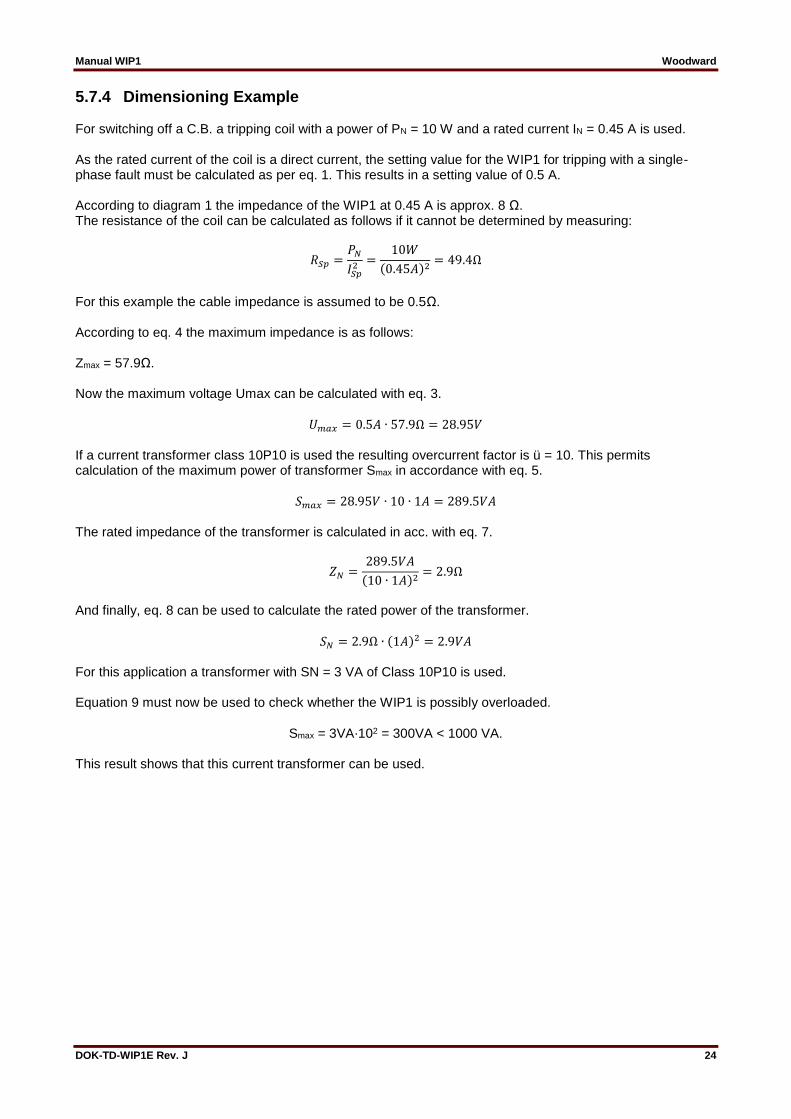
5.7.4 Dimensioning Example For switching off a C.B. a tripping coil with a power of PN = 10 W and a rated current IN = 0.45 A is used. As the rated current of the coil is a direct current, the setting value for the WIP1 for tripping with a single-phase fault must be calculated as per eq. 1. This results in a setting value of 0.5 A. According to diagram 1 the impedance of the WIP1 at 0.45 A is approx. 8 Ω. The resistance of the coil can be calculated as follows if it cannot be determined by measuring:
𝑅𝑆𝑝 =𝑃𝑁
𝐼𝑆𝑝2 =
10𝑊
(0.45𝐴)2= 49.4Ω
For this example the cable impedance is assumed to be 0.5Ω. According to eq. 4 the maximum impedance is as follows: Zmax = 57.9Ω. Now the maximum voltage Umax can be calculated with eq. 3.
𝑈𝑚𝑎𝑥 = 0.5𝐴 ∙ 57.9Ω = 28.95𝑉 If a current transformer class 10P10 is used the resulting overcurrent factor is ü = 10. This permits calculation of the maximum power of transformer Smax in accordance with eq. 5.
𝑆𝑚𝑎𝑥 = 28.95𝑉 ∙ 10 ∙ 1𝐴 = 289.5𝑉𝐴 The rated impedance of the transformer is calculated in acc. with eq. 7.
𝑍𝑁 =289.5𝑉𝐴
(10 ∙ 1𝐴)2= 2.9Ω
And finally, eq. 8 can be used to calculate the rated power of the transformer.
𝑆𝑁 = 2.9Ω ∙ (1𝐴)2 = 2.9𝑉𝐴 For this application a transformer with SN = 3 VA of Class 10P10 is used. Equation 9 must now be used to check whether the WIP1 is possibly overloaded.
Smax = 3VA⋅102 = 300VA < 1000 VA. This result shows that this current transformer can be used.

Manual WIP1 Woodward
DOK-TD-WIP1E Rev. J 25
Figure 5.8: WIP1 - power consumption
The diagram above shows the limit value of the load to which the WIP1 may be subjected in case of a short circuit. In the event that the transformer power nevertheless exceeds the limit value, it is possible to connect resistors in series into the secondary circuit.

Manual WIP1 Woodward
DOK-TD-WIP1E Rev. J 26
6. Operations and Settings By the following figure operation of the WIP1 is illustrated. The different menus can be selected by pressing push button <+> or <-> and then called up by the <SELECT/RESET> push button. If the relay is activated by transformer current the main menu is displayed. The different menus can be selected by pressing <SELECT/RESET>.
Fault memory 5
Fault memory 4
Fault memory 3
Fault memory 2
Fault memory 1
Measurements
(I> Imin)
Protection Settings
Kind of Tripping
Relay-Assignment
System Settings
Signal-Input
Fast-Trip
Signal-Input
Blocking
Relay Test
TripActivated by
"Display On"
Main menu
Activated by
transformer current
yes
no
WIP
_Z
05
Figure 6.1: Main menu overview

Manual WIP1 Woodward
DOK-TD-WIP1E Rev. J 27
6.1 Function of Push Buttons The push buttons are used for calling parameters, selecting the measuring quantities to be displayed and for changing and saving of parameters. The different menus can be selected by pressing push button <+> or <-> and then called up by the <SELECT/RESET> push button. If this push button is pressed for longer than 3 s, the display is reset. By push button <ENTER>, the set and displayed values are saved in the internal parameter memory. Incidental or unauthorized changing of parameters is prevented by an obligatory password (see chapter 6.1.4). Push button <DISPLAY ON> is to activate fault indication or for setting modes. Should no push button be pressed for 60 s, the relay deactivates the display. By pressing push buttons <SELECT/RESET>, <+> and <-> simultaneously and then activation of the relay by the <DISPLAY ON> push button, the default settings of the relay are recall from the parameter memory.
DEFAULT_SETTINGS ____AKTIVATED____
6.1.1 Measuring Value and Fault Indication In offline mode (see Chapter 5.4.2) the display is only activated after the <DISPLAY ON> push button has been pressed. Then the following is indicated on the display:
>>>PROTECTION<<< >>>>SETTINGS<<<<
Measuring values can only be read in CT-powered mode (see Chapter 5.4.1). If supply is present via C.T.s the following is indicated on display:
ISEG____15.04.97 WIP1-1__12:16:09
This display is referred to as “Main Menu” (see also Figure 6.1) and can be entered from any menu item by pressing the <SELECT/RESET> push button for about 3 s. This is the push button all fault stores and parameter blocks can be selected with.
Manual WIP1 Woodward
DOK-TD-WIP1E Rev. J 28
6.1.2 Display The menu of the data displayed can be subdivided into five groups:
Measuring values
Protection parameters
Kind of tripping/relay assignment
System parameters
Signal input parameters
Fault memory
Relay test The fault memory consists of five individual stores of identical configuration. For changing from the main menu to the first of the submenus, the <SELECT/RESET> push button is shortly to be pressed. From here the single groups can be selected via push buttons <+> and <->. To proceed to any of the individual menu points, push button <SELECT/RESET> is to be pressed.
6.1.3 Setting Procedure After a parameter value has been selected, it can be adjusted to the required value by push buttons <+> and <->.
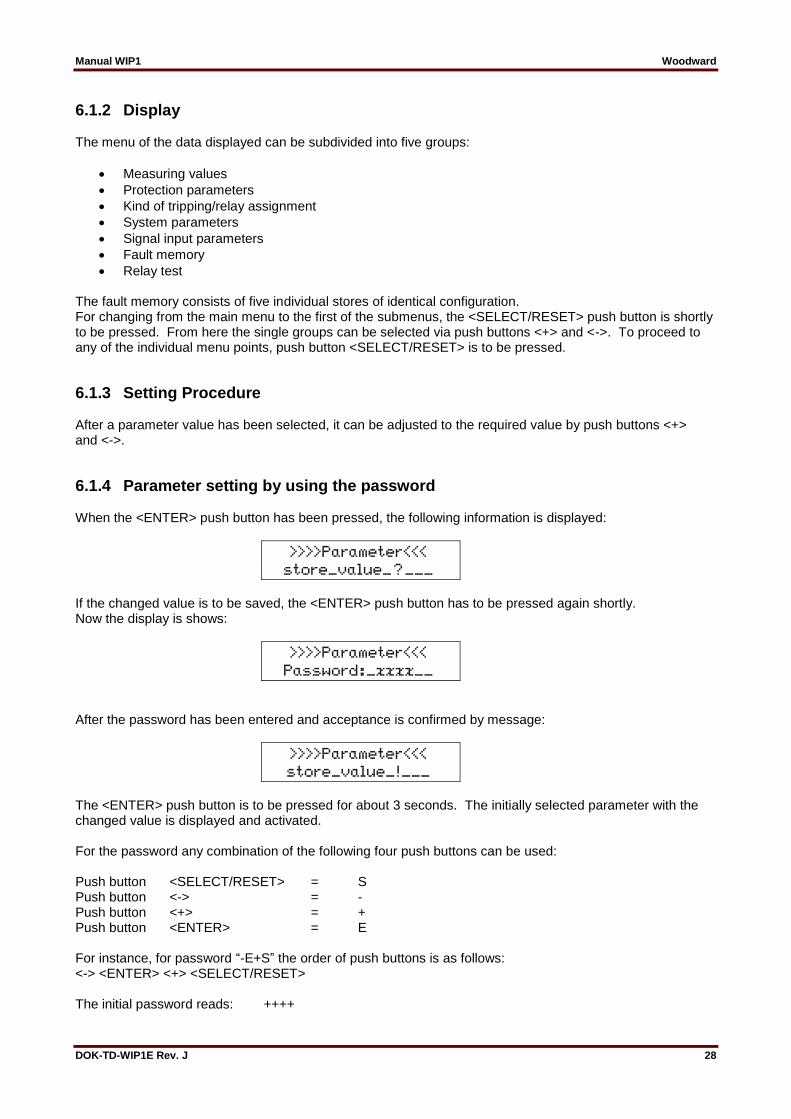
6.1.4 Parameter setting by using the password When the <ENTER> push button has been pressed, the following information is displayed:
>>>>Parameter<<< store_value_?___
If the changed value is to be saved, the <ENTER> push button has to be pressed again shortly. Now the display is shows:
>>>>Parameter<<< Password:_xxxx__
After the password has been entered and acceptance is confirmed by message:
>>>>Parameter<<< store_value_!___
The <ENTER> push button is to be pressed for about 3 seconds. The initially selected parameter with the changed value is displayed and activated. For the password any combination of the following four push buttons can be used: Push button <SELECT/RESET> = S Push button <-> = - Push button <+> = + Push button <ENTER> = E For instance, for password “-E+S” the order of push buttons is as follows: <-> <ENTER> <+> <SELECT/RESET> The initial password reads: ++++
Manual WIP1 Woodward
DOK-TD-WIP1E Rev. J 29
The place for entering the information is marked by the letter “x” on the display. If a wrong password is entered, this is indicated by the information:
>>>>Parameter<<< Wrong_Password__
By pressing the <ENTER> push button, the password can be entered again. After the password has been accepted, parameters can be set for 5 minutes without re-entering the password. During this time the procedure for saving a new value is as follows: Message “Store value?” to be acknowledged by pressing the <ENTER> push button and then after dis-play of message “Store value!” prolonged pressing of the <ENTER> push button. Provided the next setting procedure has started within the 5 minutes limit, the setting time is prolonged for further 5 minutes, otherwise the password has to be entered again.
6.2 Display of Measuring Values
>>MEASUREMENTS<< >>>>DISPLAY<<<<<
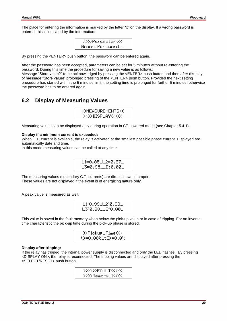
Measuring values can be displayed only during operation in CT-powered mode (see Chapter 5.4.1). Display if a minimum current is exceeded: When C.T. current is available, the relay is activated at the smallest possible phase current. Displayed are automatically date and time. In this mode measuring values can be called at any time.
L1=0.85_L2=0.87_ L3=0.95__E:0.00_
The measuring values (secondary C.T. currents) are direct shown in ampere. These values are not displayed if the event is of energizing nature only.
A peak value is measured as well:
L1ˆ0.99_L2ˆ0.98_ L3ˆ0.98__Eˆ0.00_
This value is saved in the fault memory when below the pick-up value or in case of tripping. For an inverse time characteristic the pick-up time during the pick-up phase is stored.
>>Pickup_Time<<< t>=0.00%_tE>=0.0%
Display after tripping: If the relay has tripped, the internal power supply is disconnected and only the LED flashes. By pressing <DISPLAY ON>, the relay is reconnected. The tripping values are displayed after pressing the <SELECT/RESET> push button.
>>>>>>FAULT<<<<< >>>>Memory_1<<<<
Manual WIP1 Woodward
DOK-TD-WIP1E Rev. J 30
6.3 Displaying the Pickup Phase If a pickup value is exceeded, the display will show the pickup time. If the pickup value drops below the threshold before tripping takes place, the measuring values are displayed.
6.4 Display of Tripping Values
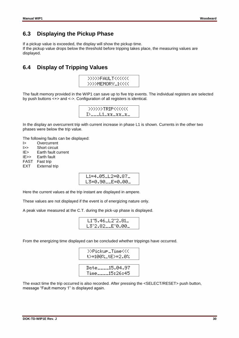
>>>>>FAULT<<<<<< >>>>MEMORY_1<<<<
The fault memory provided in the WIP1 can save up to five trip events. The individual registers are selected by push buttons <+> and <->. Configuration of all registers is identical.
>>>>>>TRIP<<<<<< I>___L1_xx_xx_x_
In the display an overcurrent trip with current increase in phase L1 is shown. Currents in the other two phases were below the trip value. The following faults can be displayed: I> Overcurrent I>> Short circuit IE> Earth fault current IE>> Earth fault FAST Fast trip EXT External trip
L1=4.05_L2=0.87_ L3=0.90__E=0.00_
Here the current values at the trip instant are displayed in ampere. These values are not displayed if the event is of energizing nature only. A peak value measured at the C.T. during the pick-up phase is displayed.
L1ˆ5.46_L2ˆ2.81_ L3ˆ2.82__Eˆ0.00_
From the energizing time displayed can be concluded whether trippings have occurred.
>>Pickup_Time<<< t>=100%_tE>=2.0%
Date____15.04.97 Time____15:26:45
The exact time the trip occurred is also recorded. After pressing the <SELECT/RESET> push button, message “Fault memory 1” is displayed again.

Manual WIP1 Woodward
DOK-TD-WIP1E Rev. J 31
Example: When selecting an inverse time characteristic a reset time of 300 s is set and the following information can be gathered in failure cases:
Number of energizing events
Max. current during each of the energizing events
Duration of the individual energizing events
Time interval between two energizing events
Interval between the energizing phases
Tripping time
Tripping value at the instant of shutdown
Manual WIP1 Woodward
DOK-TD-WIP1E Rev. J 32
6.5 Protection parameters
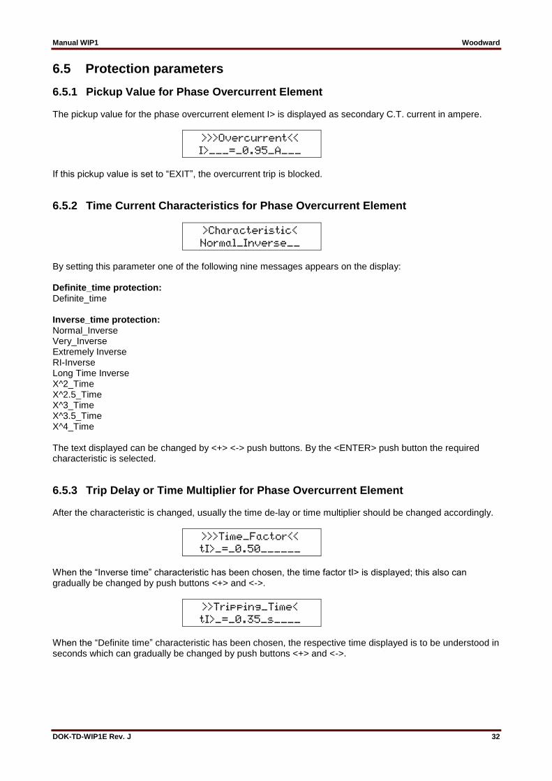
6.5.1 Pickup Value for Phase Overcurrent Element The pickup value for the phase overcurrent element I> is displayed as secondary C.T. current in ampere.
>>>Overcurrent<< I>___=_0.95_A___
If this pickup value is set to “EXIT”, the overcurrent trip is blocked.
6.5.2 Time Current Characteristics for Phase Overcurrent Element
>Characteristic< Normal_Inverse__
By setting this parameter one of the following nine messages appears on the display: Definite_time protection: Definite_time Inverse_time protection: Normal_Inverse Very_Inverse Extremely Inverse RI-Inverse Long Time Inverse X^2_Time X^2.5_Time X^3_Time X^3.5_Time X^4_Time The text displayed can be changed by <+> <-> push buttons. By the <ENTER> push button the required characteristic is selected.
6.5.3 Trip Delay or Time Multiplier for Phase Overcurrent Element After the characteristic is changed, usually the time de-lay or time multiplier should be changed accordingly.
>>>Time_Factor<< tI>_=_0.50______
When the “Inverse time” characteristic has been chosen, the time factor tI> is displayed; this also can gradually be changed by push buttons <+> and <->.
>>Tripping_Time< tI>_=_0.35_s____
When the “Definite time” characteristic has been chosen, the respective time displayed is to be understood in seconds which can gradually be changed by push buttons <+> and <->.

Manual WIP1 Woodward
DOK-TD-WIP1E Rev. J 33
6.5.4 Reset Mode for Inverse Time Tripping Characteristics for Phase Overcurrent Element
>>>Reset-Modus<< t_=_300s________
To ensure tripping, even with recurring fault pulses (packing faults) shorter than the set trip delay, the reset mode for inverse time tripping characteristics can be switched over. For adjustment t = 60 s or 300 s, the tripping time is maintained accordingly and only reset after 60 s or 300 s faultless condition. This function is off if t is set to 0. With breaking fault current, the trip delay is reset immediately and started again at recur-ring fault current.
6.5.5 Minimal Time This function is active with all inverse time tripping characteristics. It ensures that the trip delay is not faster than the set value.
>>Minimal_time<< >>tImin_=_0.1_s<
Note: The minimum time cannot be set lower than the shortest trip delay of a tripping characteristic. The latter depends on the multiplier of a tripping characteristic. Example: selected characteristic x^4-time Factor: 0.8 (see Figure 9.11) The lowest adjustable minimum time then amounts to 0.16 s. This value is automatically increased if the multiplier of the characteristic is increased.
6.5.6 Current setting for High Set Element The pickup value for the high set element appearing on the display is related to the secondary C.T. current given in ampere.
>>Short_Circuit<< I>>__2.20_A_____
When this pickup value is set to infinity (on the display appears „EXIT“), the high set element of the relay is blocked.
6.5.7 Trip Delay for High Set Element Irrespectively on the trip characteristic chosen for I>, the high set element I>> has always a definite time tripping characteristic. The indication value is displayed as seconds.
>>Tripping_Time< tI>>_=_0.35_s___

Manual WIP1 Woodward
DOK-TD-WIP1E Rev. J 34
6.5.8 Pickup Value for Earth Fault Current Element The pickup value for the earth fault current element IE> is given in ampere as secondary C.T. current.
>>>Earth_Fault<< IE>_0.05_A______
If this pickup value is set to EXIT, the earth fault current element is blocked. The earth fault current element is only activated if the current flowing in at least one of the phases is higher than the lowest adjustable threshold of the phase overcurrent element.
6.5.9 Tripping Characteristic for Earth Fault Current Element
>Characteristic< Normal_Inverse__
When adjusting the tripping characteristic one of the four following possibilities are displayed: Definite time characteristics:
Definite time earth fault current protection Inverse time earth fault current protection:
Normal Inverse
Very Inverse
Extremely Inverse
RI-Inverse
Long time Inverse The text displayed can be changed by keys <+> and <->. When pressing <ENTER> the respective characteristic is chosen.
6.5.10 Trip delay or Time Multiplier for Earth Fault Overcurrent Element (Explanatory notes, respectively principle please refer to 6.5.3)
6.5.11 Reset Mode for Normal Inverse Time Tripping Characteristics for Earth Fault Element
(Explanatory notes, respectively principle please refer to 6.5.4)
6.5.12 Minimum Tripping Time (Earth Fault Element) (Explanatory notes, respectively principle please refer to 6.5.5)
6.5.13 Current Setting for Earth Fault High Set Element (Explanatory notes, respectively principle please refer to 6.5.6)
6.5.14 Trip Delay for Earth Fault High Set Element (Explanatory notes, respectively principle please refer to 6.5.7)

Manual WIP1 Woodward
DOK-TD-WIP1E Rev. J 35
6.6 System Parameters
6.6.1 Selection of the Language
>>>>>SYSTEM<<<<< >>>>SETTINGS<<<<
Language for the messages displayed is either German or English.
>>>PARAMETER<<<< Language_English
The language can be chosen by push buttons <+> and <->.
6.6.2 Password Programming This is the menu for changing an existing password.
>>>Parameter<<<< _New_Password_?_
This inquiry is acknowledged by push button <ENTER>. By pressing push button <SELECT/RESET> this procedure is stopped and the next parameter is indicated.
Name_old________ Password_!_xxxx_
To activate a new password, the existing one has to be entered first.
_1st_input______ _Password:_xxxx_
The new password can be entered by push buttons <SELECT/RESET>, <ENTER>, <+> and <->. The place for entering the information is marked by the letter “x” on the display.
_2nd_Feed_______ _Password:_xxxx_
The password entered here must correspond with the one entered before. If this is not the case, the following message is displayed:
>>>Parameter<<<< Incorrect_Input_
By shortly pressing the <SELECT/RESET> key, the new password can be entered again. When the right password is entered, this is acknowledged by the fol-lowing message:
New_Password____ is_active_!_____
By pressing the <SELECT/RESET> push button, the next parameter is indicated.

Manual WIP1 Woodward
DOK-TD-WIP1E Rev. J 36
6.6.3 Date Setting The cursor underneath the date displayed signals that the date can be changed. For setting the correct day push buttons <+> and <-> are to be used. At first input of the correct password is required. The set value then to be acknowledged by the <ENTER> push button or proceeding to the next parameter by the <SELECT/RESET> push button. The same procedure applies for setting month and year.
>>>>Parameter<<< Date_16.04.1997_
6.6.4 Time Setting The same procedure applies for setting the time.
>>>Parameter<<<< Time____11:56:08
6.6.5 Rated Frequency Setting The adapted FFT algorithm requires the rated frequency of the object to be protected as a parameter for exact digital sampling and filtering of the input currents. Displayed is either "fN = 50 Hz" or „fN = 60 Hz“.
Rated_Frequency_ fN_50_Hz________
The rated frequency required can be adjusted by <+> or <-> and then saved by <ENTER>.
6.6.6 Setting of the Communication Slave Address (only WIP1-3)
>>Slave_Adress<< No._=__1________
By pressing keys <+> or <-> the slave address can be set within a range from 1 - 32.
6.6.7 Baud Rate Setting (only WI1-3)
>>>>Baud_Rate<<< ___9600_Baud____
The baud rate can be set by keys <+> and <-> and then be saved by pressing <ENTER>.

Manual WIP1 Woodward
DOK-TD-WIP1E Rev. J 37
6.6.8 Setting of Parity (only WIP1-3)
>>Parity_Check<< _____even_______
The following three parity settings are possible:
even parity
odd parity
no parity The setting can be changed by push buttons <+> and <-> and saved by pressing <ENTER>.
6.6.9 Indication of the Software Version In this point of the menu, the number of the relay soft-ware version can be called up. When receiving the relay description it always should be checked whether the description really applies for the actual relay soft-ware version (a respective note can be found in the index).
Software_Version V02-1.00________
6.7 Tripping Method/Relay Matrix
6.7.1 Reset Here we have to distinguish whether the LED and the bistable relay 1 are to be reset automatically or manually. Refer to Chapter 6.9
>>>>>>RESET<<<<< Manuell_________ Automatic_______
6.7.2 Tripping method This is to determine whether the C.B. is activated direct via the electric pulse output or if to be switched via an interposing C.T. circuit (see figure Figure 5.2 and Figure 5.3).
Kind_of_Tripping Electro_Pulse___
Note: If parameter is set on electric-pulse the output relay will also operate in case of tripping. If parameter is set on relay the electric impulse output doesn’t connect with a trip coil.
Manual WIP1 Woodward
DOK-TD-WIP1E Rev. J 38
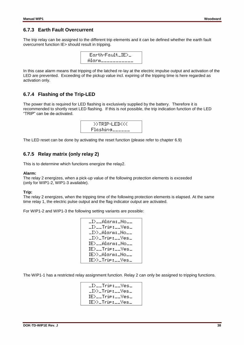
6.7.3 Earth Fault Overcurrent The trip relay can be assigned to the different trip elements and it can be defined whether the earth fault overcurrent function IE> should result in tripping.
Earth-Fault_IE>_ Alarm___________
In this case alarm means that tripping of the latched re-lay at the electric impulse output and activation of the LED are prevented. Exceeding of the pickup value incl. expiring of the tripping time is here regarded as activation only.
6.7.4 Flashing of the Trip-LED The power that is required for LED flashing is exclusively supplied by the battery. Therefore it is recommended to shortly reset LED flashing. If this is not possible, the trip indication function of the LED “TRIP” can be de-activated.
>>TRIP-LED<<< Flashing______
The LED reset can be done by activating the reset function (please refer to chapter 6.9)
6.7.5 Relay matrix (only relay 2) This is to determine which functions energize the relay2. Alarm: The relay 2 energizes, when a pick-up value of the following protection elements is exceeded (only for WIP1-2, WIP1-3 available). Trip: The relay 2 energizes, when the tripping time of the following protection elements is elapsed. At the same time relay 1, the electric pulse output and the flag indicator output are activated. For WIP1-2 and WIP1-3 the following setting variants are possible:
_I>__Alarm:_No__ _I>__Trip:__Yes_ _I>>_Alarm:_No__ _I>>_Trip:__Yes_ IE>__Alarm:_No__ IE>__Trip:__Yes_ IE>>_Alarm:_No__ IE>>_Trip:__Yes_
The WIP1-1 has a restricted relay assignment function. Relay 2 can only be assigned to tripping functions.
_I>__Trip:__Yes_ _I>>_Trip:__Yes_ IE>__Trip:__Yes_ IE>>_Trip:__Yes_
Manual WIP1 Woodward
DOK-TD-WIP1E Rev. J 39
6.8 Signal Inputs
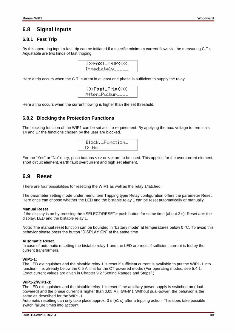
6.8.1 Fast Trip By this operating input a fast trip can be initiated if a specific minimum current flows via the measuring C.T.s. Adjustable are two kinds of fast tripping:
>>>FAST_TRIP<<<< Immediately_____
Here a trip occurs when the C.T. current in at least one phase is sufficient to supply the relay.
>>>Fast_Trip<<<< After_Pickup____
Here a trip occurs when the current flowing is higher than the set threshold.
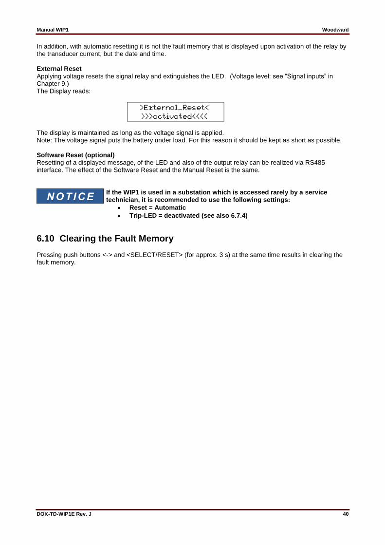
6.8.2 Blocking the Protection Functions The blocking function of the WIP1 can be set acc. to requirement. By applying the aux. voltage to terminals 14 and 17 the functions chosen by the user are blocked.
Block._Function_ I>_No___________
For the “Yes” or “No” entry, push buttons <+> or <-> are to be used. This applies for the overcurrent element, short circuit element, earth fault overcurrent and high set element.
6.9 Reset There are four possibilities for resetting the WIP1 as well as the relay 1/latched. The parameter setting mode under menu item Tripping type/ Relay configuration offers the parameter Reset. Here once can choose whether the LED and the bistable relay 1 can be reset automatically or manually. Manual Reset If the display is on by pressing the <SELECT/RESET> push button for some time (about 3 s). Reset are: the display, LED and the bistable relay 1. Note: The manual reset function can be bounded in “battery mode” at temperatures below 0 °C. To avoid this behavior please press the button “DISPLAY ON” at the same time Automatic Reset In case of automatic resetting the bistable relay 1 and the LED are reset if sufficient current is fed by the current transformers. WIP1-1: The LED extinguishes and the bistable relay 1 is reset if sufficient current is available to put the WIP1-1 into function, i. e. already below the 0.5 A limit for the CT-powered mode. (For operating modes, see 5.4.1. Exact current values are given in Chapter 9.2 “Setting Ranges and Steps”.) WIP1-2/WIP1-3: The LED extinguishes and the bistable relay 1 is reset if the auxiliary power supply is switched on (dual-powered) and the phase current is higher than 0,05 A (=5%⋅In). Without dual-power, the behavior is the same as described for the WIP1-1. Automatic resetting can only take place approx. 3 s (±1 s) after a tripping action. This does take possible switch failure times into account.
Manual WIP1 Woodward
DOK-TD-WIP1E Rev. J 40
In addition, with automatic resetting it is not the fault memory that is displayed upon activation of the relay by the transducer current, but the date and time. External Reset Applying voltage resets the signal relay and extinguishes the LED. (Voltage level: see “Signal inputs” in Chapter 9.) The Display reads:
>External_Reset< >>>activated<<<<
The display is maintained as long as the voltage signal is applied. Note: The voltage signal puts the battery under load. For this reason it should be kept as short as possible. Software Reset (optional) Resetting of a displayed message, of the LED and also of the output relay can be realized via RS485 interface. The effect of the Software Reset and the Manual Reset is the same.
If the WIP1 is used in a substation which is accessed rarely by a service technician, it is recommended to use the following settings:
Reset = Automatic
Trip-LED = deactivated (see also 6.7.4)
6.10 Clearing the Fault Memory Pressing push buttons <-> and <SELECT/RESET> (for approx. 3 s) at the same time results in clearing the fault memory.
Manual WIP1 Woodward
DOK-TD-WIP1E Rev. J 41
7. Relay Testing and Commissioning The test instructions following below help to verify the protection relay performance before or during commissioning of the protection system. To avoid a relay damage and to ensure a correct relay operation, be sure that the following conditions are fulfilled:
The rated current of the relay corresponds to the plant data on site.
The current transformer circuits are connected to the relay correctly.
All signal circuits and output relay circuits are connected correctly.
7.1 Checking the Set Values Pressing the <DISPLAY ON> push button activates the display. By repeatedly pressing the push button <SELECT/RESET>, all relay set values may be checked. Set value modification can be done with the push button <+><-> and <ENTER>. For a correct relay operation, be sure that the frequency set value (f=50/60) has been selected according to your system frequency (50 or 60 Hz).
7.2 Secondary Injection Test
7.2.1 Test Equipment
Amperemeter with class 1 or better
Single-phase voltage supply unit (adjustable from 0 to 260 V AC)
Inductance (S = 2.5 kVA, L = 65 mH, I = 10 A)
Timer to measure the operating time (Accuracy class ≤±10 ms)
Switching device
Test leads and tools
Manual WIP1 Woodward
DOK-TD-WIP1E Rev. J 42
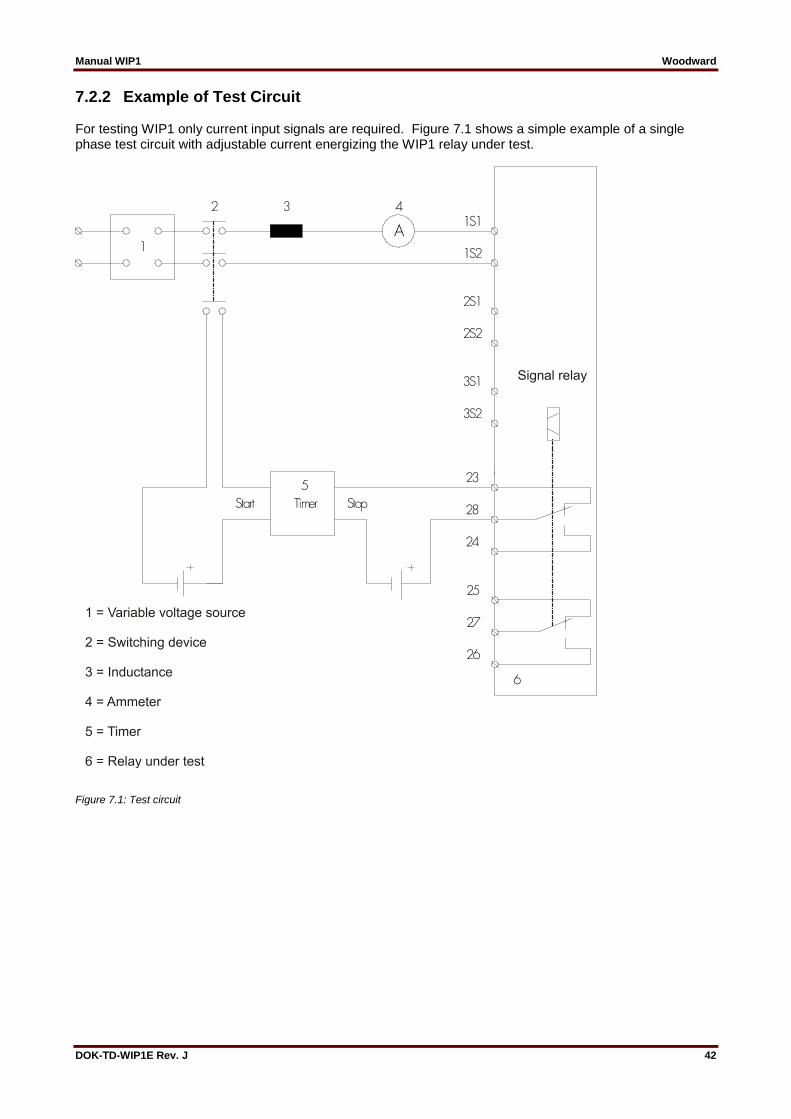
7.2.2 Example of Test Circuit For testing WIP1 only current input signals are required. Figure 7.1 shows a simple example of a single phase test circuit with adjustable current energizing the WIP1 relay under test.
Figure 7.1: Test circuit

Manual WIP1 Woodward
DOK-TD-WIP1E Rev. J 43
7.2.3 Checking the Tripping Circuits Parameter <SIGNAL INPUT BLOCKING> is followed by
>>>>>RELAY-<<<<< >>>>>TEST<<<<<<<
This mode can only be entered in battery operation, i.e. when there is no current flowing. By pressing push button <SELECT/RESET> the test mode is entered and the password queried.
>>>Relay_Test<<< _Password:_xxxx_
Pre-condition for entering the relay test mode is that the test current has been applied within 30 s. If the time has elapsed, the program returns to the standard mode and the display shows:
>>>PROTECTION<<< >>>>SETTINGS<<<<
After entering the correct password, the trip mode starts upon the following inputs.
>>TEST_CURRENT<< >>SET_TO_>1Amp<<
When 1 A is reached, test of the relay begins. The protection function is blocked through the test procedure because exceeding of the set threshold would result in tripping. The display shows:
>>>Relay_Test<<< >>>is_running<<<
In the following the test procedure is described in de-tail. Test: Electro pulse output Test: Alarm relay Test: Flag indicators These outputs are controlled for 150 ms and since they are controlled by a common processor signal, they can only be tested together. The alarm relay remains energized. Break of 1 s Self-test relay energizes for 1 s Break of 1 s

Manual WIP1 Woodward
DOK-TD-WIP1E Rev. J 44
TRIP-LED is blinking. The display shows:
>>>>>>PRESS<<<<< >SELECT-BUTTON<<
After this push button has been pressed, the alarm relay and self-test relay are de-energized and the LED should extinguish.
>>Test_current<< >>>switch-off<<<
The WIP1 indicates disconnection of the test current by the following message:
>>>>>RELAY-<<<<< >>>>>>TEST<<<<<<
Should the test current be so low that the coil fails to trip, the test will be stopped.
>>Test_stopped<< >arrest_current<

Manual WIP1 Woodward
DOK-TD-WIP1E Rev. J 45
7.2.4 Checking the Input Circuits and Measured Values Inject a current, which is less than the relay pickup cur-rent set values, in phase 1 (terminals 1S1-1S2), and check the measured current on the display by pressing the push button <SELECT/RESET>. The current can be also injected into the other current input circuits (Phase 2: terminals 2S1-2S2, Phase 3: terminals 3S1-3S2. Compare the displayed current value with the reading of the ammeter. The deviation must not exceed 5% In. By using an RMS-metering instrument, a greater deviation may be observed if the test current contains harmonics. Because the WIP1 relay measures only the fundamental component of the input signals, the harmonics will be rejected by the internal DFT-digital filter. Whereas the RMS-metering instrument measures the RMS-value of the input signals.
7.2.5 Checking the Overcurrent Element To check the relay operating time, a timer must be connected to the trip output relay contact. The timer should be started simultaneously with the current injection in the current input circuit and stopped by the trip relay contact. Set the current to a value corresponding to twice the operating value and inject the current instantaneously. The operating time measured by the timer should have a deviation of less than 3% of the set value or ±10 ms (DEFT). Accuracy for inverse time characteristics refer to IEC 255-3. Repeat the test on the other phases or with the inverse time characteristics in the similar manner. In case of inverse time characteristics the injected cur-rent should be selected according to the characteristic curve, e.g. two times IS. The tripping time may be red from the characteristic curve diagram or calculated with the equations given in chapter “Technical Data”. Please observe that during the secondary injection test the test current must be very stable, not deviating more than 1%. Otherwise the test results may be wrong.
7.2.6 Checking the High Set Element of the Relay The high set element of the WIP1 is checked in the same manner. It is important, however, that the selected test current is not too high because of trip delay at inverse time characteristics may become shorter than the high set setting. The reason is that both tripping signals operate the same tripping relay or the same electric impulse output.
Note: Where test currents >2.5 x IN are used, the thermal withstand capability of the current paths has to be considered (see Technical Data).

Manual WIP1 Woodward
DOK-TD-WIP1E Rev. J 46
7.2.7 Checking the External Blocking The external blocking input inhibits e. g. the function of the high set element of the phase current. For this purpose the parameter “Blocking Function” in the menu “Signal input blocking” for the high set element must be set to “Yes”. Then the terminals 14 and 17 are supplied with auxiliary voltage (e.g. 110 V DC). The time delay tI> should be set to EXIT for this test. Inject a test current which could cause a high set (I>>) tripping. Observe that there is no trip and alarm for the high set element. Remove the auxiliary supply voltage from the blocking input. Inject a test current to trip the relay (message “TRIP” on the display). Interrupt the test current.
7.2.8 Checking the Input “Fast Trip” The “Fast trip” function allows the unit to be tripped within the shortest possible time. A prerequisite for correct tripping is the correct setting of the parameters. In the menu “Signal input – fast trip” the setting should be “instantaneously”. If a current is now injected which is greater than the lowest adjustable overcurrent threshold and an auxiliary voltage (110 V DC) is supplied to the terminals 32 and 33, tripping takes place instantaneously (tl> = 50 ms ±10 ms).
7.2.9 Remote Trip Checking the input “Remote trip” does not require any test current. The terminals 20 and 22 are provided with supply voltage (230 V AC ±20%). This leads to tripping within 200 ms.
These terminals may only be supplied with voltage for a maximum of 2 min.
7.2.10 Test of Input „External Reset“ For testing this function, voltage is to be applied to terminals 14 and 15. The relay is activated now by it-self and in the display appears „External reset activated“.
7.3 Primary Injection Test Generally, a primary injection test could be carried out in the similar manner as the secondary injection test described above. Since the cost and potential hazards are very high for such a test, primary injection tests are usually limited to very important protective relays in the power system. Because of its powerful combined indicating and measuring functions, the WIP1 relay may be tested in the manner of a primary injection test without extra expenditure and time consumption. In actual service, for example, the measured current values on the WIP1 relay display may be compared phase by phase with the current indications of the ammeter of the switchboard to verify that the relay works and measures correctly.
Manual WIP1 Woodward
DOK-TD-WIP1E Rev. J 47
7.4 Benefits from Using the Display Battery The display battery does not affect the protection functions in any way. However, the following benefits are directly related to the battery:
Possibility to make settings or read information from the display even without sufficient supply from the C.T.s
Some information is stored as buffered (i. e. non-volatile) data in the relay’s internal memory, in particular:
o System time o Elapsed energizing time for detecting intermediate faults. (60s/300s). o Fault information o Checksums for enhanced self-tests to detect potential hardware faults
When the relay is switched on, the following information can be displayed by means of the CT current or by pressing the key <Display On>. Display of time and date begins with induction of the CT current.
ISEG____00.00.00 WIP1____00:00:00
The figure indicating the year might perhaps show undefined values. In cases the error memory fails and the energizing time has perhaps elapsed, the following text is displayed:
>>Loss_of_Data<< >>Press_Reset<<<
The information will be indicated until the key <SELECT/RESET> has been pressed for 3 s; thereafter the following is displayed:
>>Faultmemory<<< >>>>cleared<<<<<
If during this process the CT current exceeds a value of 0.5 A in one phase, the self-supervising relay energizes for 1 s. In rare cases, if data cannot be read due to an internal fault, the following is displayed:
>Internal_Fault< >>Press_Reset<<<
If during this process the CT current exceeds a value of 0.5A in one phase, the self-supervising relay energizes for 1s. Normally this error message can be reset, which means that it was only a one-off incident.
Manual WIP1 Woodward
DOK-TD-WIP1E Rev. J 48
8. Maintenance Maintenance testing is generally done on site at regular intervals. These intervals vary among users depending on many factors: e.g. the type of protective relays employed; the importance of the primary equipment being protected; the user's past experience with the re-lay, etc. For electromechanical or static relays, maintenance testing will be performed at least once a year according to the experiences. For digital relays like WIP1, this interval can be substantially longer because of the following reasons:
The WIP1 relays are equipped with very wide self-supervision functions, so that many faults in the relay can be detected and signalized during service. Important: The self-supervision output relay must be connected to a central alarm panel!
The combined measuring functions of WIP1 relays enable supervision the relay functions during service.
A testing interval of two years for maintenance will, therefore, be recommended. During a maintenance test, the relay functions including the operating values and relay tripping characteristics as well as the operating times should be tested.
Note that the relay is 100% operative without the battery. The purpose of the battery is restricted to the following:
It is possible to do settings and/or having values displayed while being “offline”, i. e. without the CTs being connected.
Fault values and system time are kept in a battery-buffered memory.
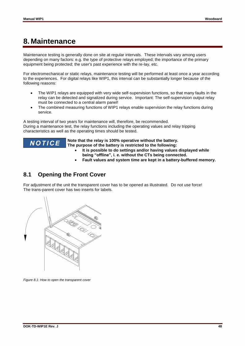
8.1 Opening the Front Cover For adjustment of the unit the transparent cover has to be opened as illustrated. Do not use force! The trans-parent cover has two inserts for labels.
Figure 8.1: How to open the transparent cover
Manual WIP1 Woodward
DOK-TD-WIP1E Rev. J 49
8.2 Display Battery The relay is buffered by a battery for feeding the LC display as well as for memorizing fault values and reset of the trip relay. Failure of the battery has no effect on the protective functions of the relay. The battery has a service life of several years. The battery has a service life of more than 10 years (depending on usage).
8.2.1 Checking the Battery The battery test is carried out by pressing the key <DISPLAY ON>. If the display indicates "Protection parameter", the battery is ok and the following is displayed:
>>>PROTECTION<<< >>>>SETTINGS<<<<
Note: Relays which have been out of order for more than one month might show "Battery voltage too low" on the display when the key <DISPLAY ON> is first pressed. The reasons for this are that, on the one hand, the capacitors are completely discharged and, on the other hand, the long storage time of the battery. To test for this case do the following: Wait until the power supply has switched off, then press the <DISPLAY ON> key again. If "Battery voltage too low" is not indicated again, then the battery is o.k. and the message had been displayed due to the long storage time.
8.2.2 Changing the Battery If at pressing the <DISPLAY ON> key the battery test finds that it should be replaced (battery voltage less than 3 V), the following is displayed:
BATTERY_Voltage_ ___too_low______
The battery is housed underneath the front cover of the relay at the lower right corner and is fastened by plug terminals.
Hazardous Voltage
The battery contacts behind the front cover may cause electric shock. Take care that the battery change is done in an ESD-compliant manner! In particular, the following activities are essential:
Disconnect from all power (supply) sources
Secure against reconnection
Verify if the equipment is dead
Connect to ground and short-circuit all phases
Cover or safeguard all live adjacent parts
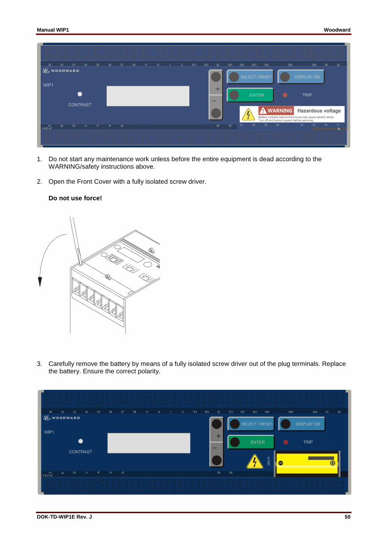
Manual WIP1 Woodward
DOK-TD-WIP1E Rev. J 50
1. Do not start any maintenance work unless before the entire equipment is dead according to the WARNING/safety instructions above.
2. Open the Front Cover with a fully isolated screw driver.
Do not use force!
3. Carefully remove the battery by means of a fully isolated screw driver out of the plug terminals. Replace the battery. Ensure the correct polarity.
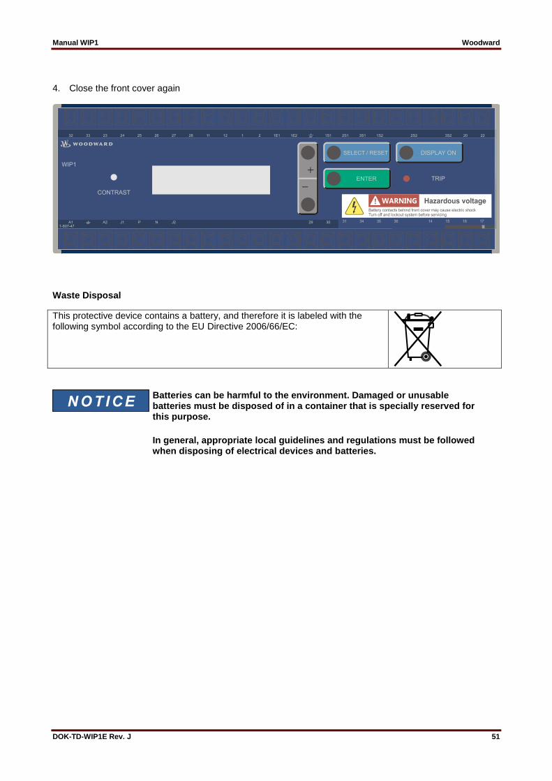
Manual WIP1 Woodward
DOK-TD-WIP1E Rev. J 51
4. Close the front cover again
Waste Disposal
This protective device contains a battery, and therefore it is labeled with the following symbol according to the EU Directive 2006/66/EC:
Batteries can be harmful to the environment. Damaged or unusable batteries must be disposed of in a container that is specially reserved for this purpose.
In general, appropriate local guidelines and regulations must be followed when disposing of electrical devices and batteries.
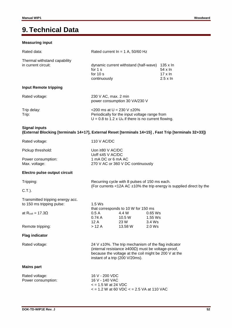
Manual WIP1 Woodward
DOK-TD-WIP1E Rev. J 52
9. Technical Data Measuring input Rated data: Rated current In = 1 A, 50/60 Hz Thermal withstand capability in current circuit: dynamic current withstand (half-wave) 135 x In for 1 s 54 x In for 10 s 17 x In continuously 2.5 x In Input Remote tripping Rated voltage: 230 V AC, max. 2 min power consumption 30 VA/230 V Trip delay: <200 ms at U = 230 V ±20% Trip: Periodically for the input voltage range from U = 0.8 to 1.2 x UN if there is no current flowing. Signal inputs (External Blocking [terminals 14+17], External Reset [terminals 14+15] , Fast Trip [terminals 32+33]) Rated voltage: 110 V AC/DC Pickup threshold: Uon ≥80 V AC/DC Uoff ≤45 V AC/DC Power consumption: 1 mA DC or 6 mA AC Max. voltage: 270 V AC or 360 V DC continuously Electro pulse output circuit Tripping: Recurring cycle with 8 pulses of 150 ms each. (For currents <12A AC ±10% the trip energy is supplied direct by the C.T.). Transmitted tripping energy acc. to 150 ms tripping pulse: 1.5 Ws that corresponds to 10 W for 150 ms at Rcoil = 17.3Ω 0.5 A 4.4 W 0.65 Ws 0.74 A 10.5 W 1.55 Ws 12 A 23 W 3.4 Ws Remote tripping: > 12 A 13.58 W 2.0 Ws Flag indicator Rated voltage: 24 V ±10%. The trip mechanism of the flag indicator (internal resistance ≥400Ω) must be voltage-proof, because the voltage at the coil might be 200 V at the instant of a trip (200 V/20ms). Mains part Rated voltage: 16 V - 200 VDC Power consumption: 16 V - 140 VAC < = 1.5 W at 24 VDC < = 1.2 W at 60 VDC < = 2.5 VA at 110 VAC

Manual WIP1 Woodward
DOK-TD-WIP1E Rev. J 53
Battery: Rated voltage: 3.0 V Signal battery voltage too low at: 2.2 V Min. operating voltage: 2.0 V Life span storage: approx.. 10 years (depends on relay configuration and application) Accuracy Basic accuracy: ±5% related to the actual current measuring value Basic accuracy of the trip time: ±3% or ±10 ms Frequency effect In the range of ±5% of the rated frequency, the current deviation is 0.5% per Hz. Dropout to pickup ratio: >97% Temperature effect At -20°C .... +55°C = ±1.5% Climatic withstand Storage: -40°C ... +85°C Operation: -20°C ... +55°C Output relays The relay 2 and watchdog relays have the following characteristics:
Load Ohmic Load (cos φ = 1)
Inductive Load (cos φ = 0,4 L/R = 7 ms)
Rated load 250 VAC 16 A 400 VAC 7 A 30 VDC 16 A
250 VAC 8 A 400 VAC 3,5 A 30 VDC 8 A
Making current 16 A
Max. contact voltage 400 VAC, 125 VDC
Max. contact current 16 A
Max. breaking capacity AC 4000 VA DC 480 W AC 2000 VA DC 240 W
mechanical life span: 30 x 106 operating cycles electrical life span: 2 x 10⁵ operating cycles at 220 V AC/6 A Contact material: silver cadmium oxide (AgCdO) Electrical and mechanical features of the relay 1 Max. operating capacity 400 V AC/2650 VA/continuous current 10 A (acc. to DIN VDE 435) mechanical life span: 1 x 10⁶ electrical life span: 1.2 x 10⁵ operating cycles at 230V AC/10A Contact material: silver-cadmium-oxide (AgCdO) Minimum operating time ca. 10 ms Returning time: ca. 10 ms Test voltage: 4000 V AC eff

Manual WIP1 Woodward
DOK-TD-WIP1E Rev. J 54
9.1 System Data Design standard: Generic standard: EN 50082-2, EN 50081-1 Product standard: EN 60255-6, IEC 255-4, BS 142 Specified ambient service Storage temperature range: - 40°C to +85°C Operating temperature range: - 20°C to +55°C Environmental protection class F as per DIN 40040 and per DIN IEC 68 2-3: relative humidity 95% at 40°C for 56 days Insulation test voltage, inputs and outputs between themselves and to the relay frame as per EN 60255-6 and IEC 255-5: 2.5 kV (eff.), 50 Hz; 1 min Impulse test voltage, inputs and outputs between themselves and to the relay frame as per EN 60255-6 and IEC 255-5: 5 kV; 1.2/50 µs; 0.5 J High frequency interference test voltage, inputs and outputs between themselves and to the relay frame as per EN 60255-6 and IEC 255-22-1: 2.5 kV/1MHz Electrostatic discharge (ESD) test as per EN 61000-4-2 and IEC 255-22-1: 8 kV air discharge, 6 kV contact discharge Electrical fast transient (Burst) test as per EN 61000-4-8 and IEC 801-4: 4 kV/2.5 kHz, 15 ms Power frequency magnetic field immunity test: 100 A/m continuously 1000 A/m for 3 s Radiated electromagnetic field disturbance test as per ENV 50140, IEC 255-22-3: electric field strength: 10 V/m Conducted electromagnetic field disturbance test as per test as per ENV 50141: electric field strength 10 V Surge immunity EN 61000-4-5: 4 kV Radio interference suppression test as per EN 55011: limit value class B Radio interference radiation test as per EN 55011: limit value class B Mechanical tests: Shock: class 1 acc. to DIN IEC 255 part 21-2 Vibration: class 1 acc. to DIN IEC 255 part 21-1 Degree of protection: Electronics: IP40 Terminals: IP20 Material : Macrolon 6030, self-extinguishing Overvoltage class: III

Manual WIP1 Woodward
DOK-TD-WIP1E Rev. J 55
9.2 Setting Ranges and Steps The WIP1 is operative with limited functionality (display of values and automatic reset) at the following current values:
single-phase starting approx. 0.35 A
two-phase starting approx. 0.22 A
three-phase starting approx. 0.17 A However, there is full functionality if the current flowing in at least one of the phases is higher than 0.5 A. (For a detailed description of how the functionality depends on the phase current see Chapter 5.4.)
Setting range Step Tolerance
I> WIP1-1 0.5...2.5 A (EXIT) WIP1-2/WIP1-3 0.2...2.5 A (EXIT)
0.01; 0.02; 0.05; 0.005; 0.01; 0.02; 0.05;
±5% of setting value ±5% of setting value
tI> 0.06 - 300 s (definite time) 0.05 -10 (inverse time)
0.01; 0.02; 0.1; 0.2; 0.5; 1.0; 2.0; 5.0; 10; 20 s 0.01; 0.02; 0.05; 0.1; 0.2; 0.5
±3% or ±10 ms ±5% for normal inverse ±7.5% for very and extremely inverse and X^2 - X^4
tmin 0,06... 2 s 0.01 s; 0.02 s; 0.05 s ±3% or ±20 ms (*)
I>> 1... 35 A (EXIT) 0.02; 0.05; 0.1; 0.2; 0.5; 1.0 A ±3% of setting value or min. ±1% In
tI>> 0.06... 2 s 0.01 s; 0.02 s; 0.05 s ±3% or ±10 ms
Table 9.1: Setting ranges phase current element
(*) Currents in the range from 0.5 to 1.5 A lead to trippings with increased trip delays (up to 50 ms).
Setting range Step Tolerance
IE> 0.05...2.0 A (EXIT) 0.001; 0.002; 0.005; 0.01; 0,02
±3% of setting value or min. ±1% In
tIE> 0.06 - 300 s (definite time)
0.05 -10 (inverse time)
0.01; 0.02; 0.1; 0.2; 0.5; 1.0; 2.0; 5.0; 10; 20 s 0.01; 0.02; 0.05; 0.1; 0.2; 0.5
±3% or ±20 ms
±5% for normal inverse ±7,5% for very and extremely inverse
tmin 0.05... 2 s 0.01 s; 0.02 s; 0.05 s ±3% or ±10 ms
IE>> 0.1... 9 A (EXIT) 0.02; 0.05; 0.1; 0.2; 0.5 A ±3% of setting value or min. ±1% In
tIE>> 0.06... 2 s 0.01 s; 0.02 s; 0.05 s ±3% or ±10 ms
Table 9.2: Setting ranges earth current element
General information related to tripping times:
If a C.T. current >0.5 A was present before tripping, or if there is an external aux. power supply (WIP1-2, WIP1-3), then the trip delay decreases (by approx. 20 ms).
Annotation to WIP1-1: The earth fault current element is only activated if the current flowing in at least one of the phases is higher than the lowest adjustable threshold of the phase overcurrent element (0,5 A).
Technical data subject to change without notice!
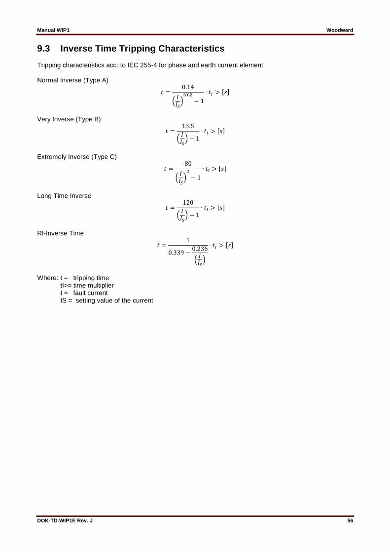
Manual WIP1 Woodward
DOK-TD-WIP1E Rev. J 56
9.3 Inverse Time Tripping Characteristics Tripping characteristics acc. to IEC 255-4 for phase and earth current element Normal Inverse (Type A)
𝑡 =0.14
(𝐼𝐼𝑆)0.02
− 1
∙ 𝑡𝐼 > [𝑠]
Very Inverse (Type B)
𝑡 =13.5
(𝐼𝐼𝑆) − 1
∙ 𝑡𝐼 > [𝑠]
Extremely Inverse (Type C)
𝑡 =80
(𝐼𝐼𝑆)2
− 1
∙ 𝑡𝐼 > [𝑠]
Long Time Inverse
𝑡 =120
(𝐼𝐼𝑆) − 1
∙ 𝑡𝐼 > [𝑠]
RI-Inverse Time
𝑡 =1
0.339 −0.236
(𝐼𝐼𝑆)
∙ 𝑡𝐼 > [𝑠]
Where: t = tripping time tI>= time multiplier I = fault current IS = setting value of the current
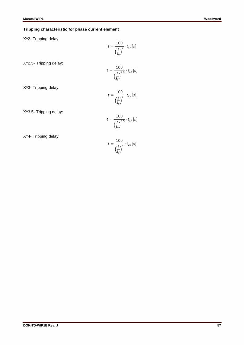
Manual WIP1 Woodward
DOK-TD-WIP1E Rev. J 57
Tripping characteristic for phase current element X^2- Tripping delay:
𝑡 =100
(𝐼𝐼𝑆)2 ∙ 𝑡𝐼>[𝑠]
X^2.5- Tripping delay:
𝑡 =100
(𝐼𝐼𝑆)2.5 ∙ 𝑡𝐼>[𝑠]
X^3- Tripping delay:
𝑡 =100
(𝐼𝐼𝑆)3 ∙ 𝑡𝐼>[𝑠]
X^3.5- Tripping delay:
𝑡 =100
(𝐼𝐼𝑆)3.5 ∙ 𝑡𝐼>[𝑠]
X^4- Tripping delay:
𝑡 =100
(𝐼𝐼𝑆)4 ∙ 𝑡𝐼>[𝑠]
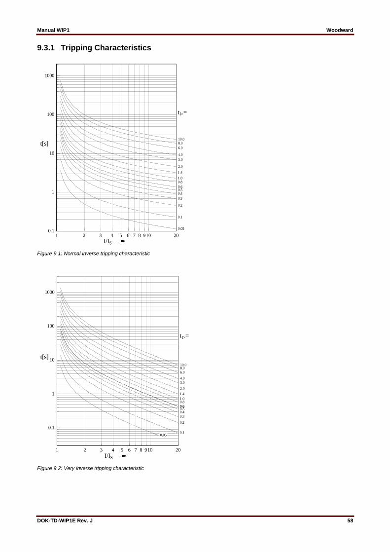
Manual WIP1 Woodward
DOK-TD-WIP1E Rev. J 58
9.3.1 Tripping Characteristics
Figure 9.1: Normal inverse tripping characteristic
Figure 9.2: Very inverse tripping characteristic
1 2 3 4 5 6 7 8 910 20
I/IS
0.1
1
10
100
1000
t[s]
tI>=
0.1
0.2
0.3
0.40.50.6
0.81.0
1.4
2.0
3.0
4.0
6.0
8.010.0
0.05
1 2 3 4 5 6 7 8 910 20
I/IS
0.1
1
10
100
1000
t[s]
tI>=
0.1
0.2
0.3
0.40.50.6
0.81.0
1.4
2.0
3.0
4.0
0.6
6.0
8.010.0
0.050.05

Manual WIP1 Woodward
DOK-TD-WIP1E Rev. J 59
Figure 9.3: Extremely inverse tripping characteristic
Figure 9.4: Long Time Inverse
1 2 3 4 5 6 7 8 910 20
I/IS
0.01
0.1
1
10
100
1000
10000
t[s] tI>=
0.30.40.50.60.81.01.4
2.0
3.04.0
6.08.010.0
0.050.05 0.10.1 0.20.2
1 2 3 4 5 6 7 8 910 20
I/IS
0.1
1
10
100
1000
10000
t[s]
tI>=
1.0
2.0
10.08.06.05.04.03.0
0.80.60.50.40.3
0.2
0.1
0.05

Manual WIP1 Woodward
DOK-TD-WIP1E Rev. J 60
Figure 9.5: Ri-Inverse
Figure 9.6: Definite time tripping characteristic
1 2 3 4 5 6 7 8 910 20
I/IS
0.1
1
10
100
t[s]
tI>=
10.0
8.07.06.0
5.0
4.0
3.0
2.0
1.0
0.80.70.6
0.5
0.4
0.3
0.2
0.1
0.05
1 10
I/IN
0.01
0.1
1
10
100
t[s]
I>I>
tI>tI>
I>>I>>
tI>>tI>>
2.52.5
300300
0.060.06
1.01.0 35352.02.0
0.060.06
0.50.5
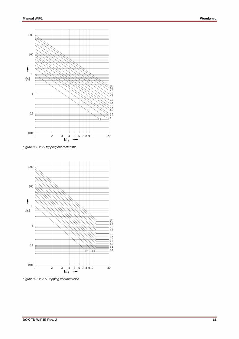
Manual WIP1 Woodward
DOK-TD-WIP1E Rev. J 61
Figure 9.7: x^2- tripping characteristic
Figure 9.8: x^2.5- tripping characteristic
1 2 3 4 5 6 7 8 910 20
I/IS
0.01
0.1
1
10
100
1000
t[s]
0.10.1
1.0
10
0.20.30.4
0.6
1.4
2.0
3.04.0
6.08.0
0.8
1 2 3 4 5 6 7 8 910 20
I/IS
0.01
0.1
1
10
100
1000
t[s]
0.10.1
1.0
10
0.20.20.30.4
0.60.8
1.4
2.0
3.04.0
6.08.0
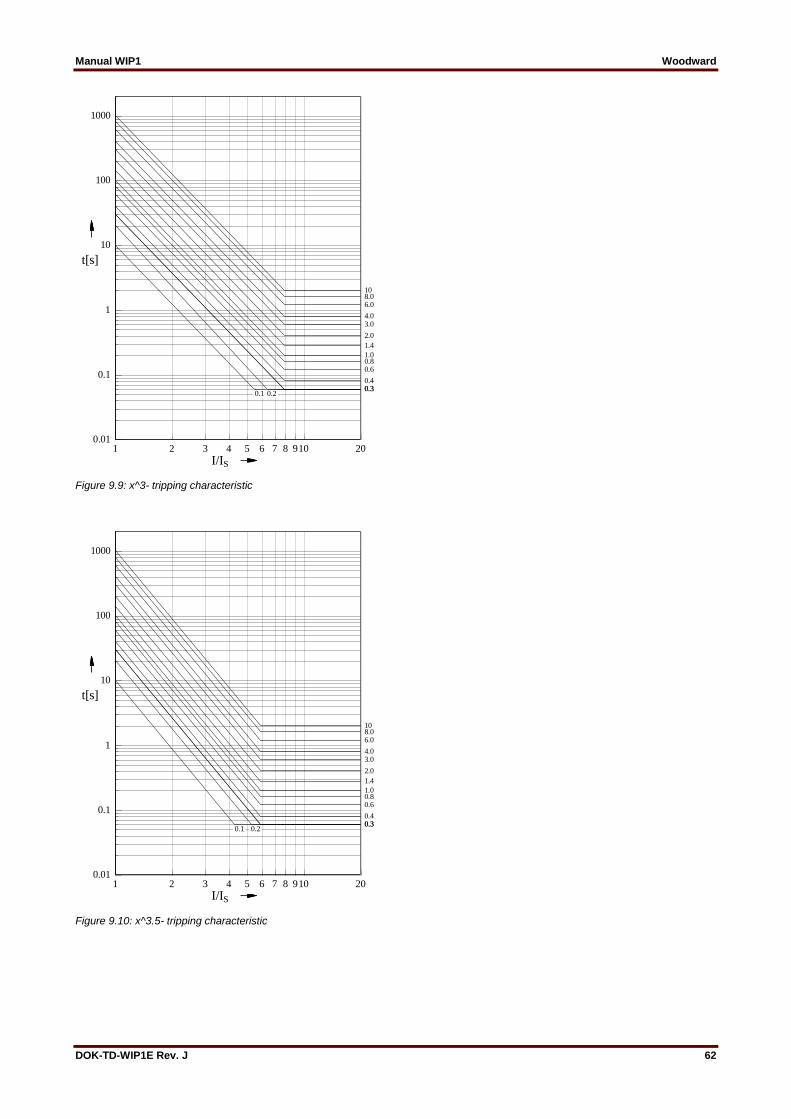
Manual WIP1 Woodward
DOK-TD-WIP1E Rev. J 62
Figure 9.9: x^3- tripping characteristic
Figure 9.10: x^3.5- tripping characteristic
1 2 3 4 5 6 7 8 910 20
I/IS
0.01
0.1
1
10
100
1000
t[s]
0.10.1
1.0
10
0.20.20.30.30.4
0.60.8
1.4
2.0
3.04.0
6.08.0
1 2 3 4 5 6 7 8 910 20
I/IS
0.01
0.1
1
10
100
1000
t[s]
1.0
10
0.20.20.30.30.4
0.60.8
1.4
2.0
3.04.0
6.08.0
0.10.1
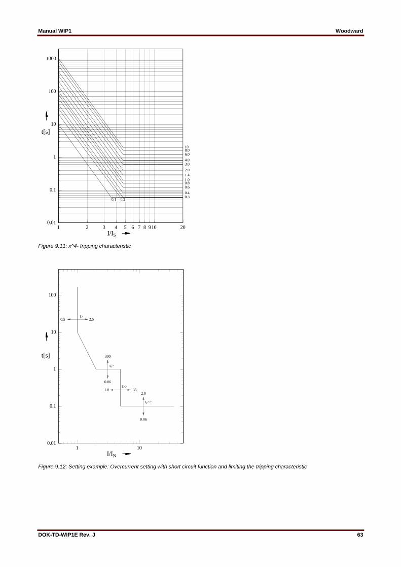
Manual WIP1 Woodward
DOK-TD-WIP1E Rev. J 63
Figure 9.11: x^4- tripping characteristic
Figure 9.12: Setting example: Overcurrent setting with short circuit function and limiting the tripping characteristic
1 2 3 4 5 6 7 8 910 20
I/IS
0.01
0.1
1
10
100
1000
t[s]
0.10.1
1.0
10
0.20.20.30.4
0.60.8
1.4
2.0
3.04.0
6.08.0
1 10
I/IN
0.01
0.1
1
10
100
t[s]
I>I>
tI>tI>
I>>I>>
tI>>tI>>
2.52.5
300300
0.060.06
1.01.0 35352.02.0
0.060.06
0.50.5
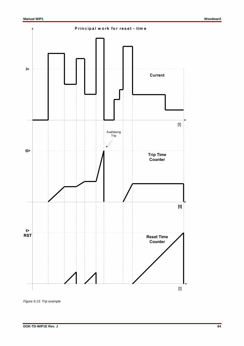
Manual WIP1 Woodward
DOK-TD-WIP1E Rev. J 64
Figure 9.13: Trip example
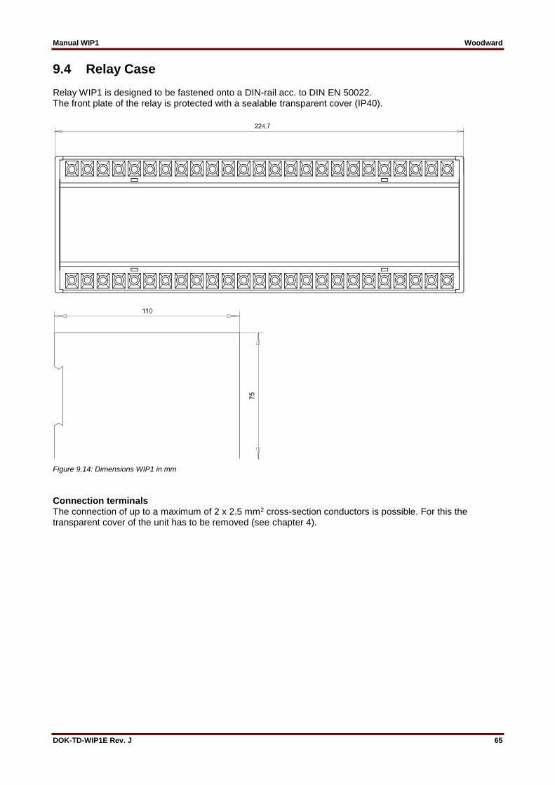
Manual WIP1 Woodward
DOK-TD-WIP1E Rev. J 65
9.4 Relay Case Relay WIP1 is designed to be fastened onto a DIN-rail acc. to DIN EN 50022. The front plate of the relay is protected with a sealable transparent cover (IP40).
Figure 9.14: Dimensions WIP1 in mm
Connection terminals The connection of up to a maximum of 2 x 2.5 mm2 cross-section conductors is possible. For this the transparent cover of the unit has to be removed (see chapter 4).
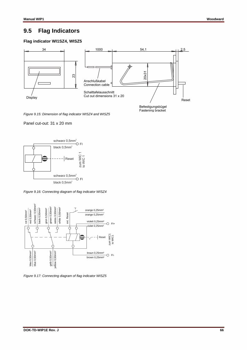
Manual WIP1 Woodward
DOK-TD-WIP1E Rev. J 66
9.5 Flag Indicators Flag indicator WI1SZ4, WISZ5
Figure 9.15: Dimension of flag indicator WISZ4 and WISZ5
Panel cut-out: 31 x 20 mm
Figure 9.16: Connecting diagram of flag indicator WISZ4
violet 0,25mm²
violett 0,25mm²
brown 0,25mm²
braun 0,25mm²
orange 0,25mm²
orange 0,25mm²
weis
s 0
,50m
m²
white 0
,50m
m²
gre
en 0
,50m
m²
grü
n 0
,50m
m²
red 0
,50m
m²
rot 0,5
0m
m²
back 0
,50m
m²
schw
arz
0,5
0m
m²
blu
e 0
,50m
m²
bla
u 0
,50m
m²
yello
w 0
,50m
m²
gelb
0,5
0m
m²
Reset
zum
WIC
1
to W
IC1
ext. R
eset
FI+
FI-
Figure 9.17: Connecting diagram of flag indicator WISZ5

Manual WIP1 Woodward
DOK-TD-WIP1E Rev. J 67
10. FAQ (Frequently Asked Questions) We will have to store the WIP1 for some time before first use. Is this possible?
In principle, there is no problem with this. However, sustained exposure to dust or humidity during storage may cause damage and reduce the lifetime of the relay. Therefore we recommend to keep the relay in its original package and keep it stored in a location free of dust and high humidity.
Later, when the relay is being installed, sufficient time should be allowed before energization for acclimatization to the ambient temperature.
Moreover, note the possibility of a false battery warning with the first energization after a long storage time, see 8.2.1.
We have to change the display battery. What should be take care of?
Take care that the battery change is done in an ESD-compliant manner!
Take care that the relay is disconnected from all power sources, secure it against reconnection and verify that the equipment is dead. Connect the relay to ground and short-circuit all phases.
As batteries can be harmful to the environment, the old battery must be disposed of in a way that follows the local regulations. For example for EU member countries, the EU Directive 2006/66/EC is applicable.
For details, including a description of how to change the battery, please consult Chapter 8.2.2 “Changing the Battery”
We have to dispose of an old relay. What should we take care of?
Take care that the relay is disconnected from all power sources, verify that all involved equipment is dead.
The relay must be disposed of in a safe manner, it should neither be burnt nor brought into contact with water sources (rivers, lakes, etc.)
In general, all appropriate local guidelines and regulations must be followed when disposing of the relay.
How is the connection of the CTs done in case of overcurrent protection with/without earth fault protection?
Please check Chapter 4 “Design” for explicit connection examples.
How can we configure the WIP1 via the HMI? See Chapter 6, in particular 6.5.
Can we make all the settings “offline”, i. e. without having the relay “live” in our substation?
Yes, the display can be switched on at any time by pressing the <DISPLAY ON> button. (It is then fed by the display battery.) The display directly makes available the parameter settings menu.
Are the protection functions still operative if the display battery is empty?
Yes, all the protection functions are independent of the display battery, i. e. in principle the relay can be operated without it. (However, see Chapter 7.4 for the benefits of the battery.)

Manual WIP1 Woodward
DOK-TD-WIP1E Rev. J 68
What is the minimum current that the relay needs to be operative?
Without dual-power, the relay is fully operational (i. e. including a permanent display of measurement values) at a minimum phase current of 0.5 A, which is also the smallest possible setting for the tripping threshold.
For WIP1-2 and WIP1-3, there is a dual power option offering several benefits, see Chapter 5.4.3 for details.
What is the minimum current that the relay needs for tripping?
Without dual-power, the minimum current requirements are the same as for being operative (0.5 A). With dual-power, the smallest setting for the phase overcurrent pickup value is 0.2 A.
What is the accuracy of measurement? See the “Technical Data” chapter, in particular the section “Accuracy”.
Can we communicate with the WIP1 via an operating software?
This is possible with the WIP1-3.
Why do we get no message on the display after a trip has occurred?
Since tripping means for a CT-powered relay that the power supply has dropped away the display is switched off. However, the tripping continues to be indicated via blinking of the Trip LED. (This blinking is fed from the display battery.)
Does this mean that we cannot access the fault values after a trip?
After pressing the <DISPLAY ON> button, the display is switched on (powered by the display battery). After a trip has occurred, the relay directly enters the Fault Memory menu, see Figure 6.1.
Doesn’t the permanent blinking of the Trip LED drain the battery empty very quickly?
In general, the blinking of an LED does not consume much electrical energy. However, for substations that are visited only rarely by any service technicians we recommend indeed to set the relay to “automatic reset” and/or disable the LED blinking, see Chapters 6.7.4 and 6.9.
Is there any self-diagnostic built in? Yes, the relay features an internal self-supervision, see e. g. Chapters 4.1, 5.2.
How can we test the operation of the relay? Please consult Chapter 7 “Relay Testing and Commissioning”.

Manual WIP1 Woodward
DOK-TD-WIP1E Rev. J 69
11. Order Form
Time overcurrent relay with multi-characteristic, self-powered
WIP1 I1 E1
3-phase current I>;I>> Self-powered
Self-powered with additional power supply 1 for 140 V AC resp. 200 V DC Self-powered with additional power supply 1, with RS485 interface
1
2
3
Rated current 1 A
Without earth current measuring (only possible for WIP1-1) With additional earth current measuring IE>; IE>> Rated current 1A
Standard (PRO OPEN DATA Protocol) Communication with MODBUS RTU Protocol (Possible with interface only)
* M
* Please leave box empty if option is not desired 1 The power pack serves as the device’s own supply, it does not supply the tripping energy for the impulse output
Flag indicator WI1-SZ4 yes no
Flag indicator WI1-SZ5 yes no
230 V/AC Voltage supply WIP1 PS
Connection of WIP1-2/3 to 230 V/AC mains
Spare battery
3.0 V spare battery WIP1 BAT2
*You can find the device version on the name plate
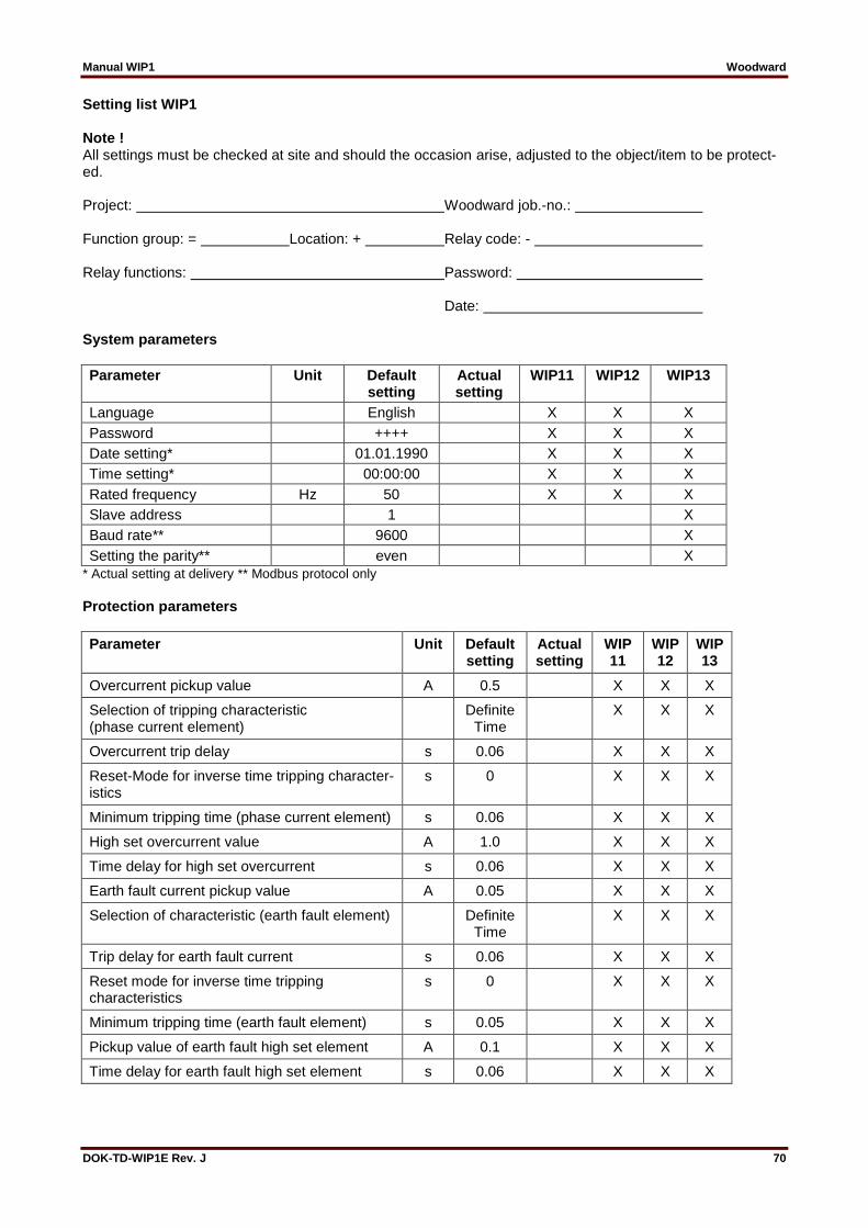
Manual WIP1 Woodward
DOK-TD-WIP1E Rev. J 70
Setting list WIP1 Note ! All settings must be checked at site and should the occasion arise, adjusted to the object/item to be protect-ed. Project: Woodward job.-no.: Function group: = Location: + Relay code: - Relay functions: Password: Date: System parameters
Parameter Unit Default setting
Actual setting
WIP11 WIP12 WIP13
Language English X X X
Password ++++ X X X
Date setting* 01.01.1990 X X X
Time setting* 00:00:00 X X X
Rated frequency Hz 50 X X X
Slave address 1 X
Baud rate** 9600 X
Setting the parity** even X
* Actual setting at delivery ** Modbus protocol only
Protection parameters
Parameter Unit Default setting
Actual setting
WIP11
WIP12
WIP13
Overcurrent pickup value A 0.5 X X X
Selection of tripping characteristic (phase current element)
Definite Time
X X X
Overcurrent trip delay s 0.06 X X X
Reset-Mode for inverse time tripping character-istics
s 0 X X X
Minimum tripping time (phase current element) s 0.06 X X X
High set overcurrent value A 1.0 X X X
Time delay for high set overcurrent s 0.06 X X X
Earth fault current pickup value A 0.05 X X X
Selection of characteristic (earth fault element) Definite Time
X X X
Trip delay for earth fault current s 0.06 X X X
Reset mode for inverse time tripping characteristics
s 0 X X X
Minimum tripping time (earth fault element) s 0.05 X X X
Pickup value of earth fault high set element A 0.1 X X X
Time delay for earth fault high set element s 0.06 X X X

Manual WIP1 Woodward
DOK-TD-WIP1E Rev. J 71
Kind of tripping
Specification Unit Default setting
Actual setting
WIP11 WIP12 WIP13
Reset Manual X X X
*Tripping via electro pulse or relay Relay X X X
Kind of tripping for IE> range Trip X X X
Trip-LED Flashing X X X
* When using a tripping coil the parameter has to be set to „Electro pulse“.
Relay matrix
Specification Unit Default setting
Actual setting
WIP11 WIP12 WIP13
Overcurrent I> Alarm No X X
Overcurrent I> Trip YES X X X
Short circuit I>> Alarm No X X
Short circuit I>> Trip YES X X X
Earth fault overcurrent IE> Alarm No X X
Earth fault overcurrent IE> Trip YES X X X
Earth short circuit IE>> Alarm No X X
Earth short circuit IE>> Trip YES X X X
Signal inputs
Default settings Actual setting WIP11 WIP12 WIP13
Function Blocked Not blocked
Blocked Not blocked
I> X X X X
I>> X X X X
IE> X X X X
IE>> X X X X
Default settings Actual setting WIP11
WIP12
WIP13
Fast tripping
Instantaneous After activation
Instantaneous After activation
X X X X
The present unit descriptions shall be valid as of software version no.: . WIP1-1: V02-1.12 WIP1-2: V12-1.17 WIP1-3: V13-1.07 WIP1-3M V13-1.06

Manual WIP1 Woodward
DOK-TD-WIP1E Rev. J 72
Woodward Kempen GmbH
Krefelder Weg 47 D – 47906 Kempen (Germany)
Postfach 10 07 55 (P.O.Box) D – 47884 Kempen (Germany)
Phone: +49 (0) 21 52 145 1
Internet
www.woodward.com
Sales
Tel.: +49 (0) 21 52 145 331 oder +49 (0) 711 789 54 510
Fax: +49 (0) 21 52 145 354 oder +49 (0) 711 789 54 101
e-mail: [email protected]
Service
Phone: +49 (0) 21 52 145 600 Telefax: +49 (0) 21 52 145 455
e-mail: [email protected]