self-stabilizing platform957123/fulltext01.pdf · 2016-09-01 · 2.1 stabilizing platforms a...
TRANSCRIPT

INOM EXAMENSARBETE TEKNIK,GRUNDNIVÅ, 15 HP
, STOCKHOLM SVERIGE 2016
Self-stabilizing platformZTäBiLAjZöR
ANDERS KARLSSON
JONATHAN CRESSELL
KTHSKOLAN FÖR INDUSTRIELL TEKNIK OCH MANAGEMENT


Self-stabilizing platform
ZTäBiLAjZöR
ANDERS KARLSSONJONATHAN CRESSELL
Bacherlor’s Thesis in Mechatronics
Supervisor: Martin Edin Grimheden Examiner: Martin Edin Grimheden Approved: 2016-06-07
TRITA MMKB 2016:30 MDAB091


Abstract
The use of accelerometers and gyroscopes has greatly increased in recent years,different applications of these are seen in everything from smartphones to mo-torcycles. The stabilizing mechanisms used for cameras may however be morewell-known. Irrespective of purpose, motorized stabilizing mechanisms com-monly utilize an inertial measurement unit to determine real-time position andmovement. This position is then analysed and an action is chosen. To improveperformance, control science is often applied.
The purpose of this report is to analyze how a common PID controller willreact to variations in load. This report will describe the construction anddevelopment of a self-stabilizing platform, controlled by two PID controllers,based on the Arduino platform. Theory behind the included components ispresented and the methods of modeling, construction and testing is discussed.
An IMU consisting of three accelerometers and three gyroscopes is used tomeasure the tilt of the platform, a Kalman filter is then used to suppress thesignal noise to reasonable levels. This was successfully achieved using Open-source code from the Arduino community.
Two DC-motors adjust the angle of the platform, one for each axis, with aPID controller each. The system was modelled for each motor to determinethe PID controller parameters that would satisfy the requirements set regard-ing speed and precision. A fast system was prioritized to assure small anglesand reduce the torque on the motor shafts. This resulted in a system withroughly 0.1 seconds of rise time, 1.3 seconds settling time and 18% overshootat a 10° step.
By conducting step response tests using the demonstrator, the research ques-tion could be answered. It was found that a PID controller tuned for a specificsystem will have a performance drop but not become unstable when load isvaried, up to the level of load that causes too large amounts of torque for themotors to counter.
iii


SammanfattningSjälv-stabiliserande plattform
Användningen av accelerometrar och gyroskop har ökat de senaste åren, olikatillämpningar finns i allt från smarta telefoner till motorcyklar. Däremot ärtill exempel stabiliseringsmekanismen använd till kameror bättre känd. Oav-sett syfte är det vanligt att motoriserade stabiliseringsmekanismer använder entröghetsmätningsenhet, bättre känd som en IMU, för att avgöra position ochrörelse i realtid. Denna position är sedan analyserad och en handling väljs. Föratt förbättra prestanda appliceras ofta reglerteknik på systemet.
Syftet med denna rapport är att undersöka hur en normal PID-regulator kom-mer att reagera vid variationer i belastning. Rapporten beskriver konstruktio-nen och utvecklingen av en själv-stabiliserande plattform, styrd av två PID-regulatorer, baserad på Arduino-plattformen. Bakomliggande teori kring kom-ponenterna presenteras och metoder för modellering, konstruktion och testningdiskuteras.
En IMU bestående av tre accelerometrar och tre gyroskop används för attmäta plattformens lutning, ett Kalman-filter dämpar sedan bruset i signalentill godtagbara nivåer. Detta åstadkoms med hjälp av kod från Open-sourcekällor från Arduino-communityt.
Två DC-motorer justerar vinkeln på plattformen, en för var axel, med en PID-regulator var. Systemet modellerades för vardera av motorerna, för att bestäm-ma parametrar för PID-regulatorerna som kunde uppfylla de satta kraven påhastighet och precision. Vikt lades på att systemet skulle vara snabbt för attgarantera små vinklar och minimalt vridmoment på motorernas utgående axlar.Detta resulterade i ett system med c:a 0.1 sekunders stigtid, insvängningstidpå 1.3 sekunder och ett översläng på hela 18% vid ett steg på 10°.
Forskningsfrågan kunde besvaras med tester genomförda på demonstratören.Det gavs att en PID-regulator anpassad för ett visst system endast får sämreprestanda utan att bli instabil vid förändringar i belastning, upp till den viktsom hindrar motorerna från att rotera på grund av för stort vridmoment.
v


Preface
We would like to present our thanks to our supervisor Martin Edin Grimheden forassisting us throughout this project. We would also like to thank Jan Stamer forhelping us in the workshop, Staffan Qvarnström for helping with the demonstrator,Tomas Östberg for lending us tools and materials and Lei Feng for helping us withthe control science.
Anders KarlssonJonathan Cressell
Stockholm, May, 2016
vii


Contents
Abstract iii
Sammanfattning v
Preface vii
Contents ix
Nomenclature xi
1 Introduction 11.1 Background . . . . . . . . . . . . . . . . . . . . . . . . . . . . . . . . 11.2 Purpose . . . . . . . . . . . . . . . . . . . . . . . . . . . . . . . . . . 11.3 Scope . . . . . . . . . . . . . . . . . . . . . . . . . . . . . . . . . . . 21.4 Method . . . . . . . . . . . . . . . . . . . . . . . . . . . . . . . . . . 21.5 Similar projects . . . . . . . . . . . . . . . . . . . . . . . . . . . . . . 3
2 Theory 52.1 Stabilizing platforms . . . . . . . . . . . . . . . . . . . . . . . . . . . 52.2 Inertial measurement unit . . . . . . . . . . . . . . . . . . . . . . . . 62.3 Pulse Width Modulation . . . . . . . . . . . . . . . . . . . . . . . . . 62.4 PID controller . . . . . . . . . . . . . . . . . . . . . . . . . . . . . . . 72.5 DC Motor . . . . . . . . . . . . . . . . . . . . . . . . . . . . . . . . . 82.6 Kalman filter . . . . . . . . . . . . . . . . . . . . . . . . . . . . . . . 9
3 Demonstrator 113.1 Problem formulation . . . . . . . . . . . . . . . . . . . . . . . . . . . 113.2 Software . . . . . . . . . . . . . . . . . . . . . . . . . . . . . . . . . . 113.3 Electronics . . . . . . . . . . . . . . . . . . . . . . . . . . . . . . . . 12
3.3.1 DC Motor . . . . . . . . . . . . . . . . . . . . . . . . . . . . . 123.3.2 Micro-controller - Arduino NANO . . . . . . . . . . . . . . . 133.3.3 H-bridge - L298N . . . . . . . . . . . . . . . . . . . . . . . . . 143.3.4 IMU - MPU6050 . . . . . . . . . . . . . . . . . . . . . . . . . 14
3.4 Hardware . . . . . . . . . . . . . . . . . . . . . . . . . . . . . . . . . 15
ix

3.5 Final design . . . . . . . . . . . . . . . . . . . . . . . . . . . . . . . . 17
4 Calculations 194.1 Transfer function . . . . . . . . . . . . . . . . . . . . . . . . . . . . . 19
4.1.1 Motor 1 mechanics . . . . . . . . . . . . . . . . . . . . . . . . 204.1.2 Motor 2 mechanics . . . . . . . . . . . . . . . . . . . . . . . . 204.1.3 Resulting calculations . . . . . . . . . . . . . . . . . . . . . . 21
4.2 System requirements . . . . . . . . . . . . . . . . . . . . . . . . . . . 23
5 Test and results 255.1 Tests . . . . . . . . . . . . . . . . . . . . . . . . . . . . . . . . . . . . 25
5.1.1 Signal filtering . . . . . . . . . . . . . . . . . . . . . . . . . . 255.1.2 Step response . . . . . . . . . . . . . . . . . . . . . . . . . . . 25
5.2 Results . . . . . . . . . . . . . . . . . . . . . . . . . . . . . . . . . . . 265.2.1 Signal filtering . . . . . . . . . . . . . . . . . . . . . . . . . . 275.2.2 Step response . . . . . . . . . . . . . . . . . . . . . . . . . . . 28
6 Discussion and conclusions 316.1 Discussion . . . . . . . . . . . . . . . . . . . . . . . . . . . . . . . . . 31
6.1.1 Control science . . . . . . . . . . . . . . . . . . . . . . . . . . 316.1.2 Tests . . . . . . . . . . . . . . . . . . . . . . . . . . . . . . . . 316.1.3 Signal filtering . . . . . . . . . . . . . . . . . . . . . . . . . . 326.1.4 Error sources . . . . . . . . . . . . . . . . . . . . . . . . . . . 32
6.2 Conclusions . . . . . . . . . . . . . . . . . . . . . . . . . . . . . . . . 33
7 Recommendations and future work 357.1 Recommendations . . . . . . . . . . . . . . . . . . . . . . . . . . . . 357.2 Future work . . . . . . . . . . . . . . . . . . . . . . . . . . . . . . . . 35
Bibliography 37
Appendices
A Additional information 41A.1 Calculation of the dynamic friction constant b . . . . . . . . . . . . . 41
x

Nomenclature
Symbols
Symbols Description
b Dynamic friction constant [Nm·s]Bt Control matrixe Static erroreEMF Back EMFFt State transition matrixG Transfer functiong Gravitation constant [m/s2]i Current [A]J Total moment of inertia per motor [kg·m2]J1 Motor 1 moment of inertia [kg·m2]J2 Motor 2 moment of inertia [kg·m2]Jr Rotor moment of inertia [kg·m2]Ke Back EMF constant [mV/rpm]KD Derivative part parameterKI Integrative part parameterKP Proportional part parameterKt Torque constant [mN/A]L Inductance [H]l Distance from rotational axis to center of mass [m]m Mass [kg]Qt Covariance matrixR Resistance [Ω]T Motor torque [Nm]t Time [s]u Input signalut Control vectorV Voltage [V]VN Nominal voltage [V]wt Vector containing noisy terms at time txt State matrix at time t
xi

xt−1 State matrix at time t − 1θ Angle [°]θ Angular velocity [rad/s]θ Angular accerelation [rad/s2]
AbbreviationsAbbreviation Description
CAD Computer Aided DesignEMF Electro-Motive ForceI2C Inter-Integrated CircuitIMU Inertial Measurement UnitMDC Motion-Disturbance CompensatingPID ProportionalIntegralDerivativePLA PolylactidePWM Pulse Width ModulationRpm Revolutions per minute
xii

Chapter 1
Introduction
This chapter explains the background to this project, along with its purpose andlimitations.
1.1 BackgroundThe need for stabilizing mechanisms is wide-spread. Various techniques are appliedin search of the ideal solution. A common application is camera stabilization, lesscommon are perhaps self-leveling anti-motion sickness seats or surgery platforms[Grober, D.E., 2009]. These systems share the importance of maintaining a con-stant position or direction relative to a point of reference, regardless of disturbanceor movement in space. A method for measuring this position is using an InertialMeasurement Unit (IMU) consisting of gyroscopes and accelerometers, commonlyused in self-stabilizing platforms.
The Motion-Disturbance Compensating (MDC), or self-stabilizing, platform aimsto correct angular deviations using motors. The signal from the measuring unit re-quires filtering and in order to obtain any reasonable level of system rapidity controlscience must be applied. The motors are seen as two individual systems, one for thex-axis and one for the y-axis. A ProportionalIntegralDerivative (PID) controller iswell suited for systems with one signal in, voltage, and one signal out, angle, suchas the one in question.
1.2 PurposeThis report aims to investigate the robustness of a PID controlled self-stabilizingplatform, in order to answer the research question:
“How will a PID controlled system react to variations in load?”
1

CHAPTER 1. INTRODUCTION
The result of this could help widening the range of methods used to create stabilizingmechanisms. In doing so, solutions to problems such as the previously mentionedsurgery platform could be found.
1.3 ScopeThe demonstrator will be limited to two degrees of freedom, rotation around thex-axis, roll, and y-axis, pitch. Rotation around the z-axis, yaw, and linear transla-tion movement will be disregarded as it was found to be irrelevant for a stabilizingplatform. Open-Source code will be used for the sensor signal filter and the Inter-intergrated circuit (I2C) communication bus and will as such be explained onlybriefly. Further, the demonstrator will be constructed as a small scale test rig forsmall loads. This project is a bachelor’s thesis.
1.4 MethodA mathematical model of the system was created in order to theoretically designa control system that could later be applied to the demonstrator, which was con-structed in order to test the theory. Prior to construction a realistic 3D-model wasdrawn up using Solid Edge in order to determine values such as the distance tothe centre of mass and create models for 3D-printing. Necessary PID controllerparameters were evaluated using MATLAB Simulink.
2

1.5. SIMILAR PROJECTS
1.5 Similar projectsSelf-stabilizing platforms are nowadays a relatively popular home-project and manydifferent types were found during research. Most of these projects use servo motors,see figure 1.1, in other words, most are not feedback systems. The downside ofservo motors in this application is that they cannot be regulated outside their builtin regulator, which in most cases makes the construction slow [Rivello, 2011]. Thegreat advantage is its simplicity, the angle of the measurement unit can be feddirectly to the servo motor [Rony Chakraborty, 2014].
Figure 1.1: Typical construction, Source:[Rivello, 2011]
A less common approach to this problem is using DC-motors and implementing aseparate controller to the system [S. Narkar, S. Bhalekar, T. Nawge, K. Parab, P.Pati, 2013]. An advantage of this is that they can be regulated with an independentcontroller and it can, for example, be tuned for an aggressive fast response or adefensive slower response. However, this will greatly increase the complexity of thesystem and as such require a higher level of understanding of the problem.
3


Chapter 2
Theory
The theory chapter provides basic knowledge necessary to understand the problemand the following solution.
2.1 Stabilizing platformsA self-stabilizing platform usually takes in account at least two angles; roll andpitch. The purpose of such a platform is for it to maintain close-to zero degrees ofangle towards the direction of gravity, in other words, to stay horizontal. In order toachieve this each angle has to be measured. This can be done in a number of ways.A rotary encoder can be used to measure the rotation of the motor shaft and havethe motor adjust accordingly [M. Ruderman, J. Krettek, F. Homann, T. Bertram,2008]. Another option is to use a device capable of measuring the platforms currentangle, such as a gyroscope and accelerometer combination. This also enables thesystem to cope with the mounting (base) platform being tilted, unlike the encodersolution which can only adjust when the motor is rotated as pictured in figure 2.1.
Figure 2.1: a) Platform not adjusting when mount is tilted b) Platform adjustingwhen mount is tilted, Drawn in:[Microsoft Powerpoint 2016]
5

CHAPTER 2. THEORY
2.2 Inertial measurement unitAn IMU of the scale used for this project often consists of a combination of threeaccelerometers and three gyroscopes placed orthogonally to each other, representinga coordinate system. An accelerometer measures G-forces, or inertial acceleration.A gyroscope measures its rotational position in relation to an arbitrarily chosen co-ordinate system. The reason for using both a gyroscope and accelerometer becomesclear when considering their weaknesses. A gyroscope will have an accumulatingerror and can as such often not be used alone while an accelerometer has a problemwith the gravity component. These two are fortunately easily combined and willcompensate each others weaknesses very well [Gabor Paller, 2011].
2.3 Pulse Width ModulationPulse Width Modulation (PWM) allows for digital signals to appear to be analogue.A digital signal is either a zero or a one, while an analogue signal has a largerspectrum. Rather than having one output channel for each voltage, a PWM signalis used [Johansson, 2013a]. The PWM signal is a pulse of ones and zeros allowingthe voltage to be set to a percentage of the maximum output voltage of the usedchannel. A PWM signal is usually between 0 and 255, where 0 is 0% of the availableoutput voltage and 255 is 100%. Over a pulse, a signal of 127 will result in the signalsent being one for half of the period, and zero for the rest. This will be interpretedby the motor as a voltage of half the maximum voltage. Presented in the figure 2.2is a system with output voltage of 5V, where for example the 25% duty cycle resultsin an output signal of 1.25V. PWM is thus normally used to control the rotationspeed of DC motors, which also is the case in this project.
Figure 2.2: PWM signal in an Arduino, Source:[Arduino.cc, 2016c]
6

2.4. PID CONTROLLER
Further, the frequency of the pulse can be adjusted depending on the requirementsof the system. Typical frequency is 490Hz [Arduino.cc, 2016a], which is audible tothe human ear. By increasing the PWM frequency, the noise can be removed.
2.4 PID controllerThe PID control system consists of a proportional (P) part, integral (I) part andderivative (D) part, and is a very common feedback control system [Lee Payne,2014]. It is commonly applied to systems that can be mathematically modelled andhave a one to one input-output relation.
The proportional part is simple; the error signal is proportional to the controlsignal. If the error is big, so is the control signal. The problem with this is that asthe error gets smaller so does the control signal and the error will therefore never befully eliminated (theoretically), this is called a steady state error. In order to reducethis error, the proportional constant can be increased, though this will reduce thestability of the system.
To properly eliminate the steady state error an integral part is required. The inte-gral part will historically register the error between the reference and output signalsand increase the input signal accordingly. This can however also result in decreasedstability, why a derivative part is introduced [Paul Avery, 2009].
The derivative part can increase stability by predicting the movement of the system,the prediction is however then clearly sensitive to disturbances and measurementnoise. As such, signal filtering becomes more important.
Conclusively, the PID will be the sum of the above presented three parts as
u(t) = Kpe(t) + KI
∫ t
0e(τ) dτ + KD
(d
dte(t)
)(2.1)
where KP , KI and KD are the tuning parameters for proportional, integral andderivative control respectively, and e(t) is the error between reference signal andoutput signal.
7

CHAPTER 2. THEORY
2.5 DC MotorDirect Current motor, commonly known as DC-motor, is as the name suggests anelectrical motor powered by DC. The most common DC-motors have an odd numberof poles, where the ingoing current direction determines the outgoing rotationaldirection.
Figure 2.3: Brushed DC-motor, Source:[Zgcmotor.com, 2015]
Small models often consist of a permanent magnet as stator and poles connectedto the rotor made up of coils that create a magnetic field [Giorgos Lazaridis, 2010].These electromagnetic fields change direction throughout one cycle. As seen infigure 2.3 the brushes are in contact with the commutator, which leads the currentto different coils depending of the rotors orientation.
Figure 2.4: DC motor circuit, Source:[ctms.engin.umich.edu, 2016]
8

2.6. KALMAN FILTER
The electrical circuit of a DC motor can be modelled as depicted in figure 2.4.Applying Kirchoff’s law of voltage [Johansson, 2013b] results in
V − eEMF = L
(di
dt
)+ Ri (2.2)
where V is the voltage, eEMF is the back EMF, L is the inductance, i is the currentand R is the circuit resistance. Furthermore, the back EMF can be written as
eEMF = Keθ (2.3)
with Ke being the motor voltage constant and θ the angular velocity. From theseequations the relation between voltage and angular velocity can be derived. Sincethe angular velocity is proportional to the ingoing voltage, a DC motor is easilycontrolled using Pulse-Width Modulation (PWM) and a H-bridge, and as such wellsuited for the task at hand.
2.6 Kalman filterThe angle readings from an IMU carry much noise, which results in them requiringfiltering before a reasonably true angle can be measured. Without filtering, thevariations in the measured angle may result in deceiving a controller in to reactingto untrue movement. To remove these noisy readings a Kalman-filter, first devel-oped by NASA in collaboration with Dr. R. Kalman for the Apollo program [L.A.McGee, S.F. Schmidt, 1985], is a good choice. The Kalman-filters main advantagesare the quality of its estimation and relatively low complexity [Zaknich, 2005]. Adisadvantage is that it only works for gaussian linear systems, for non-gaussianand non-linear systems a particle filter would be preferable [M.S. Arulampalam, S.Maskell, N. Gordon, T. Clapp, 2002].
For most systems it is possible to calculate an expected outcome of a specific ac-tion, in other words a prediction for the sample space of the next state. When theprediction is made and the next state is initiated, noisy readings from the sensorgives another sample space. These two combined give a good approximation ofthe systems real state [Ramsey Faragher, 2012]. The algorithm is recursive, whichnarrows the sample space continuously. This is the basic thought of the methodcalled Kalman-filtering and is visualized in figure 2.5. The fact that the Kalmanfilter does not require any history other than its previous state makes it well suitedfor continuously changing systems such as a self-stabilizing platform [Tim Babb,2015].
9

CHAPTER 2. THEORY
Figure 2.5: The Kalman cycle, Source:[Codeproject.com, 2016]
This method would not be very useful if it were not for the key properties of theGaussian distribution. The product of two or more distributions returns anotherGaussian distribution with a new mean value and variance [Tim Babb, 2015]. Asmentioned above the required information has already been obtained, in the formof predictions made from the previous state and measurements from the currentstate. Both are Gaussian distributed, and together the current states sample spacenarrows.
10

Chapter 3
Demonstrator
In this chapter the design of the prototype is described with further details on eachcomponent.
3.1 Problem formulation
A number of aspects had to be considered in the construction of the demonstra-tor. Firstly, in order to achieve a stable system, excessive moment of inertia on themotor shaft had to be reduced. This ruled out a number of otherwise interestingconstruction ideas that could have been realized by using stronger and faster sys-tems, that in turn would require more resources. Secondly, the platform needs tobe able to move fairly freely in both axes. Lastly, the IMU had to be mounted onthe top plate in order to provide just measurements of the platforms position andmovement.
3.2 Software
The software consists of the IMU signal analysis and a Kalman filter, followed byPID controllers for each motor. The raw IMU data is pulled through the Kalmanfilter in order to obtain a more stable signal, each filtered angle value is then com-pared to the reference value, zero, followed by a PID controller. The direction of themotor depends on the output signal from the PID controller. After this comparisonis made, the output signal is sent along with the direction information to the H-bridge, which then results in the motors behaving accordingly. This is graphicallypresented in figure 3.1.
11

CHAPTER 3. DEMONSTRATOR
Figure 3.1: Programming flowchart, Drawn in:[draw.io]
3.3 ElectronicsThe components presented in this section are discussed individually.
3.3.1 DC MotorThe motors used in this project are Faulhaber 2842S006C with an output power of5,33 W each. They are equipped with gears of a ratio 14:1, significantly increasingthe torque at the cost of rotation speed. Considering the rotation speed pre-gearingis 5100rpm, the geared motor will be fast enough for the provided purpose. Table 3.1contains further key information from the motor data sheet [MicroMo ElectronicsInc., 2016].
12

3.3. ELECTRONICS
Table 3.1: Faulhaber 2842S006C specifications
Denotation Value Source
Nominal voltage VN 6 [V ] DatasheetTerminal resistance R 1.6 [Ω] Datasheet
Induction L 145 [µH] DatasheetBack EMF constant Ke 1.150 [mV/rpm] Datasheet
Torque constant Kt 10.9 [mNm/A] DatasheetRotor inertia Jr 9.7026 · 10−7 [kg · m2] Datasheet
Inertia motor 1 J1 2.538 · 10−3 [k · gm2] Solid EdgeInertia motor 2 J2 2.797 · 10−3 [kg · m2] Solid Edge
Dynamic friction constant b 9.8382 · 10−4 [Nm · s] Calculated (appendix A.1)
3.3.2 Micro-controller - Arduino NANO
The Arduino NANO is a smaller version of Arduino UNO, having largely the samespecifications. The NANO was chosen over other Arduino designs for its size, seefigure 3.2.
Figure 3.2: The Arduino NANO, Source:[etechpk.net, 2016]
The Arduino is an open source based platform designed for simplicity. The NANOis provided with a ATmega328 micro-controller, which can be called its brain. Fur-thermore, the NANO is equipped with eight analog pins, 14 digital pins, of which sixare PWM enabled, and a mini-USB port for communicating and programming. AllArduino models are programmed with included software, which is based on C/C++[Arduino.cc, 2016b].
13

CHAPTER 3. DEMONSTRATOR
The PWM ports on the Arduino are set up in pairs and have different frequen-cies at which the signal is sent [Arduino.cc, 2016a]. Too low a frequency will impairthe performance of the system, and the fluctuating voltage will even be audible tothe human ear. The default setting of the NANO was therefore modified in orderto increase the frequency of used ports [Arduino.cc, 2016d].
3.3.3 H-bridge - L298N
An H-bridge, sometimes called motor driver, allows pole switching, which practicallymeans changing the motors rotational direction. Its main purpose is however toallow for an external power supply to the motors. The L298N, displayed in figure3.3, was chosen because of its capability to control two motors simultaneously,provide each motor with a maximum current of 2A and also supply 5V output tothe Arduino. The motor voltage supply can handle voltages from 5 to 35 V [JohnBoxall, 2014].
Figure 3.3: The L298N, Source:[artofcircuits.com, 2016]
3.3.4 IMU - MPU6050
The MPU6050 is a combination of a three-axis gyroscope and a three-axis accelerom-eter [Sparkfun.com, 2016] and is probably the most important part of the stabilizingmechanism. It provides information of its angular position and acceleration. Withits small size shown in figure 3.4 and vast Open-source library it was consideredideal for this project.
14

3.4. HARDWARE
Figure 3.4: The Sparkfun MPU6050, Source:[sparkfun.com, 2016]
3.4 HardwareThe full construction displayed in figure 3.5 consists of five main parts, the handle,motor mounts, shaft brackets, platform mount and platform. Most of these partswere 3D-printed using an Ultimaker 2 from CAD models created in Solid Edge ST7.
Figure 3.5: Main construction
15

CHAPTER 3. DEMONSTRATOR
The handle was ergonomically designed for optimum grip and ease of use, madeout of PLA-plastic using a 3D printer. The construction was made portable bymounting the Arduino NANO and H-bridge on the handle. The four almost equalmotor mounts fit motor 2 to the handle and motor 1 to motor 2. These parts were3D-printed with an Ultimaker 2 in PLA-plastic.
To transfer the motor torque from the shaft to the motor attachments nave-likebrackets were constructed. By a radially located screw these were locked on tothe flat side of shaft. The axle brackets were mainly made in a turning machine.The long arm attached to the platform was designed for simplicity and maximumangular displacement. A rectangular slot by the platform mounting point created afitting for the IMU. The platform was made of Plexiglas and was shaped in a lasercutter. For reference, the side length was 200 mm and its thickness was 5 mm.
16

3.5. FINAL DESIGN
3.5 Final designThe demonstrator is a handheld construction and cannot stand on its own. As seenin figure 3.6 a docking block has been constructed to simplify testing and demon-stration. The block was 3D-printed using very little material, the walls were only0.8mm thick and the inside filled to 5%.
Figure 3.6: Demonstrator
17


Chapter 4
Calculations
This chapter illustrates the calculations, simplifications and mechanics of the con-structions transfer function.
4.1 Transfer functionIn order to determine suitable parameters for the PID controller using MATLABPID tuner, a transfer function was required. This transfer function could then beused to simulate various tests in the same program. Briefly described, the transferfunction translates the input signal to an output signal. In the current system, theinput signal is the PWM signal, or voltage, and the output signal is the angle readfrom the IMU.
In order to construct the transfer function, a number of simplifications were made.Firstly, the static friction of DC motors is non-linear and therefore needed to bedisregarded in order for a linear transfer function to be determinable. Secondly, theangular fluctuations of the platform are considered small enough for the sinusoidalvalue of θ to be almost equal to θ. Lastly, the transfer function is calculated withoutany load on the platform.
Furthermore, the system was divided in to two subsystems, one per motor, as themechanics of these differ.
19

CHAPTER 4. CALCULATIONS
4.1.1 Motor 1 mechanicsMotor 1 is mounted on the shaft of motor 2. On the shaft of Motor 1, the platformis attached.
Figure 4.1: Motor 1 torque balance
Presented in figure 4.1 are the moment of inertia from the platform and its mountingJ1, motor torque T , rotation angle θ, angular velocity θ and dynamic friction b.
4.1.2 Motor 2 mechanicsMotor 2 is mounted on the handle and has motor 1 attached to its shaft as shownin figure 4.2.
Figure 4.2: Motor 2 torque balance
The equation describing Motor 2 differs from Motor 1 only in the moment of inertiaJ2.
20

4.1. TRANSFER FUNCTION
4.1.3 Resulting calculations
If the magnetic field is assumed to be constant, the motor torque can be calculatedby
T = Kti (4.1)
This results in the motor torque being proportional to the current i by the torqueconstant Kt [Johansson, 2013c].
Figure 4.3: Torque by gravity on platform
As shown in figure 4.2 and 4.3 the torque equation around the shaft will be calculatedby
T − Jθ − bθ − mgl · sin(θ) = 0 (4.2)
21
CHAPTER 4. CALCULATIONS
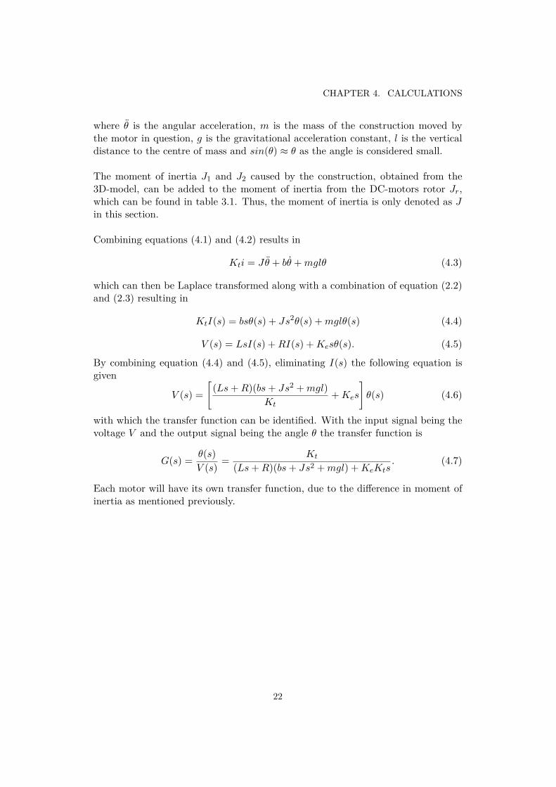
where θ is the angular acceleration, m is the mass of the construction moved bythe motor in question, g is the gravitational acceleration constant, l is the verticaldistance to the centre of mass and sin(θ) ≈ θ as the angle is considered small.
The moment of inertia J1 and J2 caused by the construction, obtained from the3D-model, can be added to the moment of inertia from the DC-motors rotor Jr,which can be found in table 3.1. Thus, the moment of inertia is only denoted as Jin this section.
Combining equations (4.1) and (4.2) results in
Kti = Jθ + bθ + mglθ (4.3)
which can then be Laplace transformed along with a combination of equation (2.2)and (2.3) resulting in
KtI(s) = bsθ(s) + Js2θ(s) + mglθ(s) (4.4)
V (s) = LsI(s) + RI(s) + Kesθ(s). (4.5)
By combining equation (4.4) and (4.5), eliminating I(s) the following equation isgiven
V (s) =[
(Ls + R)(bs + Js2 + mgl)Kt
+ Kes
]θ(s) (4.6)
with which the transfer function can be identified. With the input signal being thevoltage V and the output signal being the angle θ the transfer function is
G(s) = θ(s)V (s)
= Kt
(Ls + R)(bs + Js2 + mgl) + KeKts. (4.7)
Each motor will have its own transfer function, due to the difference in moment ofinertia as mentioned previously.
22

4.2. SYSTEM REQUIREMENTS
4.2 System requirementsIn order for the system to be able to cope with the torque caused by the platform,the center of mass must be in line with the rotational axes. To achieve this despitedisturbances, a fast system is required. Translated to control science, the rise timemust be low. This causes the overshoot to increase, which in turn must be limited.Lastly, the steady state error must be small for the platform to be considered level.As a result, requirements were set up as presented in table 4.1 for a step of 10°.
Table 4.1: System requirements
Requirement Value
Risetime < 1 sOvershoot < 10 %
Settling time < 3 sSteady state error < 2°
23


Chapter 5
Test and results
In this chapter the methodology surrounding the tests is explained, followed by apresentation of the results.
5.1 TestsTests are required to answer the research questions, as well as to determine theperformance of and fine-tune the PID parameters. Further, a test was performedto identify the signal noise post filtering.
5.1.1 Signal filteringThe signal noise reduction achieved by Kalman filtering had to be determined. TheIMU was placed in a locked position and the signal was read over a period of time.The raw angular data was compared to the filtered angle data as well as the meanof the raw data for reference.
5.1.2 Step responseWhen testing a system of this character step response tests are commonly used.A step response test is conducted by allowing the system to enter a steady state,upon which a change in the reference signal is made. In the case of a stabilizingplatform, the test should monitor performance when a disturbance occurs. Thiscan be modelled by varying the reference signal by a set amount and recording thetime and angle deviation. All tests were repeated multiple times to assure reliableresults, and a test that closely corresponded with the mean values of all tests wasselected for each result.
A number of tests were conducted with the PID parameters determined and appliedto the model. The angle was set to 10° in one or both axes after which is was resetto 0°, to monitor the step response. Both the setting and removal of the referencepoint shift was recorded.
25

CHAPTER 5. TEST AND RESULTS
In order to investigate the reliability of the PID controller when the characteris-tics of the system changes, a weight of 200g was placed on the platform and thetests were repeated without adjusting the controller parameters. The weight wasthen increased in order to investigate the limits of the system.
5.2 ResultsWith the help of the MATLAB Simulink PID Tuner, a set of suitable parameterscould be determined. These were further fine-tuned on the demonstrator to achieveperformance that satisfy the system requirements presented in section 4.2. The finalvalues were as presented in table 5.1. It was also found that weights above 290gwill prevent the system from eliminating the steady state error by causing too largeamounts of torque.
Table 5.1: Chosen system parameters
Parameter Controller motor 1 Controller motor 2
KP 18.94 15.94KI 0.54 0.58KD 25.48 25.65
26

5.2. RESULTS
5.2.1 Signal filteringA number of identical tests provided a mean value for the raw angle. The filteredangle and raw data from one test was then compared to this as presented in figure5.1.
0 2000 4000 6000 8000 10000Time (ms)
-3.4
-3.2
-3
-2.8
-2.6
-2.4
-2.2
Ang
le (
deg)
KalmanRawMean raw
Figure 5.1: Signal readings steady IMU
The data was sampled at a rate of 5ms. The raw data peaked at ± 0.57°, while theKalman filtered value only had a deviation of ± 0.12°.
27

CHAPTER 5. TEST AND RESULTS
5.2.2 Step responseThe results from the step response tests were as shown below.
0 1000 2000 3000 4000Time (ms)
-0.5
0
0.5
1
1.5
Am
plitu
de
Motor 2 clockwiseMotor 2 counterclockwise
(a) X
0 1000 2000 3000 4000Time (ms)
-0.5
0
0.5
1
1.5
Am
plitu
deMotor 1 clockwiseMotor 1 counterclockwise
(b) Y
0 1000 2000 3000 4000Time (ms)
-0.5
0
0.5
1
1.5
Am
plitu
de
Motor 1 clockwiseMotor 1 counterclockwiseMotor 2 clockwiseMotor 2 counterclockwise
(c) X and Y
Figure 5.2: Step response without load
Figure 5.2 shows results from the tests without additional load on the platform.Rise time ranges from 60 to 103ms, settling time was around 1300ms and the over-shoot was roughly 16% when tilted in one axis, 30% when in two. The steady stateerror was between 0.07 and 0.34°.
28

5.2. RESULTS
After placing the weight on the platform, the performance was as shown in figure 5.3.
0 1000 2000 3000 4000Time (ms)
-0.5
0
0.5
1
1.5
Am
plitu
de
Motor 2 clockwiseMotor 2 counterclockwise
(a) X
0 1000 2000 3000 4000Time (ms)
-0.5
0
0.5
1
1.5
Am
plitu
de
Motor 1 clockwiseMotor 1 counterclockwise
(b) Y
0 1000 2000 3000 4000Time (ms)
-0.5
0
0.5
1
1.5
Am
plitu
de
Motor 1 clockwiseMotor 1 counterclockwiseMotor 2 clockwiseMotor 2 counterclockwise
(c) X and Y
Figure 5.3: Step response with 200g load
While the rise time remained around 100ms, overshoot increased to around 40% forall scenarios, and settling time came close to 3 seconds with a steady state error of0.2°to 0.8°.
29

CHAPTER 5. TEST AND RESULTS
An overview of the key values from both simulations and demonstrator tests areshown in table 5.2.
Table 5.2: System performance
Motor 1 Motor 2 Requirement
Risetime 0.103 s 0.085 s < 1 sOvershoot 18.7% 15% < 10 %
Settling time 1.345 s 1.104 s < 3 sSteady state error 0.07° 0.22° < 2°
30

Chapter 6
Discussion and conclusions
This chapter consists of discussions concerning the results obtained in the variousparts of the project, followed by conclusions.
6.1 DiscussionThe discussion is held in regard to achieving a functional system and obtaining ajust answer to the research question.
6.1.1 Control scienceSince the controller was designed for a system without load, performance was ex-pected to drop. This could be tuned further in order to achieve a less sensitivesystem, though that would much likely be at the cost of the original systems per-formance.
Higher performance could be obtained by discretizing the controllers and thusmatching the measurement frequency with the PID output frequency, rather thanusing a delay which freezes the program for a short period. This would howeverrequire a significantly higher sys- tem complexity.
The overshoot was higher than the specified requirements all scenarios, while thespeed requirements were met with much margin. Thus, by lowering the speed amore stable system and preferable performance could be achieved.
6.1.2 TestsThe tests were satisfactory in the aspect of analyzing the system, however sincethe test data was retrieved from the IMU, reliability can be questioned. The IMUreadings tend to spike upon sudden movements, resulting in untrue readings. Thetest results with load were also not ideal due to the performance without load notbeing close enough to the requirements set.
31

CHAPTER 6. DISCUSSION AND CONCLUSIONS
6.1.3 Signal filteringAs shown in section 5.2.1 the Kalman filter reduces signal noise by a factor of 5.This is a significant difference and greatly improves the performance of the con-troller. Had the noise been greater, a low-pass filter may have been required for thederivative part of the controller to stabilize. As the Kalman filter is anticipative,untrue readings may appear momentarily upon sudden accelerations, causing trou-ble when testing. This too was preferred to the higher complexity or computationalstrength required by other options.
6.1.4 Error sourcesWhen determining the transfer function, a number of simplifications were made.Firstly, the static friction of the DC motors was disregarded from, something thatwould have a noticeable impact on performance at small angles. This could be ac-counted for by applying a non-linear model, which would also allow for the torqueequation to be corrected, where the sinusoidal function was simplified.
Further error sources worth mentioning are the approximations made when de-termining the dynamic friction constant and the moment of inertia for both motors.The data sheet for the motors also specifies that the coil resistance can vary by±12%. There is also a small, barely noticeable, step in the gear which will haveimpact on performance when changing directions.
As mentioned in section 6.1.3, the readings from the IMU may not always rep-resent the actual angle, especially when there is large and sudden overshoot. As itwas not certain that the values were exact, slightly rounded values were presentedin the results.
Having assumed small angles also resulted in the mathematical model not beingvery accurate at larger errors, and the system would therefore not have the ex-pected performance.
Lastly, the motors have different current to angular velocity ratios depending onthe rotational direction. This resulted in there being larger overshoot when startingin the direction where the motors were stronger, and a slower system when in theopposite direction.
32
6.2. CONCLUSIONS
6.2 ConclusionsThe purpose of this report was to answer a research question.
How will a PID-controlled system react to variations in load?
The system remained stable despite the load being increased, as seen in chapter5.2, though performance decreased. Overshoot increased greatly, explained by theincreased moment of inertia and torque requirement. The impact on performanceis greater when the system moves in both directions compared to when limited toone direction. By optimizing the controller parameters, a less sensitive system canbe achieved.
33


Chapter 7
Recommendations and future work
In this section a few recommendations for the project are presented, along with ideasfor future work.
7.1 RecommendationsSince the transfer function determined in this project was limited to be linear, fairlylarge simplifications were made. These are relevant to the performance of the sys-tem, as such it would be recommended to create a non-linear model in MATLABSimulink. This would improve controller tuning abilities greatly.
A higher quality IMU could improve readings, and a motor without gears wouldremove the step. For anyone interested in the subject the Open-Source communityrelated to Arduino can provide examples of code for signal filtering, IMU readings,PID control.
7.2 Future workThe assertion in section 4.1.3 that the angle is small causes instability when it isnot, this can be resolved by implementing defensive and aggressive parameters thatwill switch depending on the platforms current angle, with defensive parameters atlarger angles.
Performance can also be improved by matching the PWM output frequency withthe rest of the system, so that the controller calculates new signals at the same paceas the PWM sends new signals. This would increase accuracy.
Naturally, a lot of time can be spent improving the controller parameters for bothcontrollers by trial and error.
35


Bibliography
[Arduino.cc, 2016a] Arduino.cc (2016a). analogWrite(). Available from: https://www.arduino.cc/en/Reference/AnalogWrite [cited 2016-05-07].
[Arduino.cc, 2016b] Arduino.cc (2016b). ARDUINO NANO. Available from: http://www.arduino.cc/en/Main/ArduinoBoardNano [cited 2016-05-06].
[Arduino.cc, 2016c] Arduino.cc (2016c). Picture: PWM. Available from: https://www.arduino.cc/en/uploads/Tutorial/pwm.gif [cited 2016-06-03].
[Arduino.cc, 2016d] Arduino.cc (2016d). Secrets of Arduino PWM. Available from:https://www.arduino.cc/en/Tutorial/SecretsOfArduinoPWM [cited 2016-05-07].
[artofcircuits.com, 2016] artofcircuits.com (2016). Picture: L298N. Available from:http://artofcircuits.com/wp-content/uploads/2013/10/L298N-module.jpg [cited 2016-05-05].
[Codeproject.com, 2016] Codeproject.com (2016). Picture: Kalman-cycle. Avail-able from: http://www.codeproject.com/KB/recipes/865935/cycle.png[cited 2016-05-05].
[ctms.engin.umich.edu, 2016] ctms.engin.umich.edu (2016). Picture: DC-Circuit. Available from: http://ctms.engin.umich.edu/CTMS/Content/MotorPosition/Simulink/Modeling/figures/motor.png [cited 2016].
[etechpk.net, 2016] etechpk.net (2016). Picture: ARDUINO NANO. Availablefrom: http://www.etechpk.net/wp-content/uploads/2016/02/ARDUINO_NANO_03.png [cited 2016-05-05].
[Gabor Paller, 2011] Gabor Paller (2011). Better mo-tion control using accelerometer/gyroscope sensor fu-sion. Available from: http://www.slideshare.net/paller/better-motion-control-using-accelerometergyroscope-sensor-fusion[cited 2016-05-05].
[Giorgos Lazaridis, 2010] Giorgos Lazaridis (2010). How DC Motors are made andhow they work. Available from: http://pcbheaven.com/wikipages/How_DC_Motors_Work/ [cited 2016-05-06].
37

BIBLIOGRAPHY
[Grober, D.E., 2009] Grober, D.E. (2009). Autonomous, self leveling, self correctinganti-motion sickness chair, bed and table. US Patent 7,490,572. Available from:https://www.google.com/patents/US7490572 [cited 2016-05-07].
[Johansson, 2013a] Johansson, H. (2013a). Elektroteknik. In Johansson, H., editor,Elektroteknik, page 7:45, Stockholm, SWE. Universitets service AB.
[Johansson, 2013b] Johansson, H. (2013b). Elektroteknik. In Johansson, H., editor,Elektroteknik, page 1:16, Stockholm, SWE. Universitets service AB.
[Johansson, 2013c] Johansson, H. (2013c). Elektroteknik. In Johansson, H., editor,Elektroteknik, pages 7:12–7:13, Stockholm, SWE. Universitets service AB.
[John Boxall, 2014] John Boxall (2014). Tutorial - L298N Dual Motor ControllerModule 2A and Arduino. Available from: http://tronixlabs.com.au/news/tutorial-l298n-dual-motor-controller-module-2a-and-arduino/ [cited2016-05-02].
[L.A. McGee, S.F. Schmidt, 1985] L.A. McGee, S.F. Schmidt (1985). Discov-ery of the Kalman Filter as a Practical Tool for Aerospace and Industyr.Available from: http://ntrs.nasa.gov/archive/nasa/casi.ntrs.nasa.gov/19860003843.pdf [cited 2016-05-03].
[Lee Payne, 2014] Lee Payne (2014). The Modern Industrial Workhorse: PID Con-trollers. Available from: http://www.techbriefs.com/component/content/article/ntb/features/feature-articles/20013 [cited 2016-05-06].
[M. Ruderman, J. Krettek, F. Homann, T. Bertram, 2008] M. Ruderman, J. Kret-tek, F. Homann, T. Bertram (2008). Optimal State Space Control ofDC Motor. Available from: https://www.researchgate.net/publication/216232528_Optimal_State_Space_Control_of_DC_Motor [cited 2016-05-07].
[MicroMo Electronics Inc., 2016] MicroMo Electronics Inc. (2016). Se-ries 2842 ... C. Available from: http://www.me.mtu.edu/~wjendres/ProductRealization1Course/Motor_Specs.pdf [cited 2016-05-04].
[M.S. Arulampalam, S. Maskell, N. Gordon, T. Clapp, 2002] M.S. Arulampalam,S. Maskell, N. Gordon, T. Clapp (2002). Available from: http://www.cse.psu.edu/~rtc12/CSE598G/papers/ParticleFilterTutorial.pdf [cited 2016-05-02].
[Paul Avery, 2009] Paul Avery (2009). Introduction to PID control. Avail-able from: http://machinedesign.com/sensors/introduction-pid-control[cited 2016-05-06].
[Ramsey Faragher, 2012] Ramsey Faragher (2012). Understanding the Ba-sis of the Kalman Filter Via a Simple and Intuitive Derivation .Available from: http://www.cl.cam.ac.uk/~rmf25/papers/Understanding%20the%20Basis%20of%20the%20Kalman%20Filter.pdf [cited 2016-04-22].
38

[Rivello, 2011] Rivello (2011). Self balancing waiter tray. (or almost it) . Avail-able from: http://forum.arduino.cc/index.php/topic,68755.0.html [cited2016-05-06].
[Rony Chakraborty, 2014] Rony Chakraborty (2014). MPU6050 DMP with Pro-tonBasic. Available from: http://www.ekushebangla.com/DMP_MPU6050.html[cited 2016-05-06].
[S. Narkar, S. Bhalekar, T. Nawge, K. Parab, P. Pati, 2013] S. Narkar, S.Bhalekar, T. Nawge, K. Parab, P. Pati (2013). Self Balancing Platform.Available from: http://www.ijctee.org/NSPIRE2013/IJCTEE_0313_Special_Issue_24.pdf [cited 2016-05-06].
[sparkfun.com, 2016] sparkfun.com (2016). Picture: MPU6050. Avail-able from: https://cdn.sparkfun.com//assets/parts/6/3/5/5/11028-04.jpg [cited 2016-05-05].
[Sparkfun.com, 2016] Sparkfun.com (2016). SparkFun Triple Axis Accelerometerand Gyro Breakout - MPU-6050. Available from: https://www.sparkfun.com/products/11028 [cited 2016-05-06].
[Tim Babb, 2015] Tim Babb (2015). How a kalman filterworks, in pictures. Available from: http://www.bzarg.com/p/how-a-kalman-filter-works-in-pictures/ [cited 2016-04-01].
[Zaknich, 2005] Zaknich, A. (2005). Principles of Adaptive Filters and Self-learningSystems. Springer-Verlag, Austrailia, 1nd edition.
[Zgcmotor.com, 2015] Zgcmotor.com (2015). Picture: DC-motor. Availablefrom: http://www.zgcmotor.com/upload/Image/20150521/20150521150754_33455.jpg [cited 2016-05-05].
39


Appendix A
Additional information
A.1 Calculation of the dynamic friction constant b
The dynamic friction constant b is not represented in the data sheet [MicroMo Elec-tronics Inc., 2016], therefore the tests and calculations of this constant are made.The dynamic friction is the counteracting force the rotor is exposed to when themotor is operating.The test were conducted with help of a tachometer to keep track of the rotors an-gular velocity θ at different input voltage V . The values were stored in vectors andanalyzed in MATLAB.
The balance in the torque equation (4.1) with friction constants included is rep-resented by
Kti = Jθ + bθ + Fc · sgn(θ) (A.1)where Fc is the motors static friction which is assumed to be zero when the rotoris in motion and sgn(θ) represents this by
sgn(θ) =
1 if θ = 00 otherwise
(A.2)
The current i of a DC motor can be represented by [Johansson, 2013c]
i = U − Keθ
R, (A.3)
by substitution into equation (A.1) and rearranging gives
Jθ = KtU
R−
(KtKe
R+ b
)θ − Fc · sgn(θ). (A.4)
When the motor has reached constant speed the angular acceleration θ is non-existent and the angular velocity θ can be extracted as
θ = 1KtKe + bR
(KtU − RFc · sgn(θ)
). (A.5)
41

APPENDIX A. ADDITIONAL INFORMATION
From the measurements by MATLABs built in function polyfit() the constants ofthe linear regression were approximated and thus b could be calculated.
The test results are displayed in table A.1
Table A.1: Testresults
Voltage [V ] 0.6 2 2.5 3 3.5 4 4.5 5 5.5 6
Angular velocity [rad/s] 0 10.4 13.8 17.1 20.3 23.5 27.4 30.6 34.0 37.5
and graphically represented in figure A.1 where the red line represents the linearregression.
0 1 2 3 4 5 6
Voltage [V]
0
5
10
15
20
25
30
35
40
Ang
ular
vel
ocity
[rad
/s]
Measured valuesApproximated function
Figure A.1: Measurements and approximated function
From the values obtained in MATLAB and equation (A.5) the dynamic friction bwas found to be 9.8382 · 10−4 [Nm · s].
42


TRITA MMKB 2016:30 MDAB091
www.kth.se