the effect of stabilizing piles on a self-supported earth
TRANSCRIPT
Full Terms & Conditions of access and use can be found athttp://www.tandfonline.com/action/journalInformation?journalCode=umgt20
Download by: [Yonsei University] Date: 06 November 2016, At: 16:56
Marine Georesources & Geotechnology
ISSN: 1064-119X (Print) 1521-0618 (Online) Journal homepage: http://www.tandfonline.com/loi/umgt20
The Effect of Stabilizing Piles on a Self-SupportedEarth-Retaining Wall
Jaeuk Sim, Sangseom Jeong & Kyoungchul Kim
To cite this article: Jaeuk Sim, Sangseom Jeong & Kyoungchul Kim (2016) The Effectof Stabilizing Piles on a Self-Supported Earth-Retaining Wall, Marine Georesources &Geotechnology, 34:3, 265-279, DOI: 10.1080/1064119X.2015.1004767
To link to this article: http://dx.doi.org/10.1080/1064119X.2015.1004767
Accepted author version posted online: 29Apr 2015.Published online: 29 Apr 2015.
Submit your article to this journal
Article views: 139
View related articles
View Crossmark data
The Effect of Stabilizing Piles on a Self-SupportedEarth-Retaining Wall
JAEUK SIM1, SANGSEOM JEONG1, and KYOUNGCHUL KIM2
1Department of Civil and Environmental Engineering, Yonsei University, Seoul, Republic of Korea2R & BD Institute of Kolon Global Co., Ltd., Gyeonggi, Republic of Korea
Received 16 November 2014, Accepted 4 January 2015
The behavior of a self-supported earth-retaining wall with stabilizing piles was investigated using a numerical study and field testsin urban excavations. Special attention is given to the reduction of lateral earth pressures acting on a retaining wall with stabilizingpiles. Field tests at two sites were performed to verify the performance of the instrumented retaining wall with stabilizing piles. Anumber of 3D numerical analyses were carried out on the self-supported earth-retaining wall with stabilizing piles to assess theresults stemming from wide variations of influencing parameters such as the soil condition, the pile spacing, the distance betweenthe front pile and the rear pile, and the embedded depth. Based on the results of the parametric study, the maximum horizontaldisplacement and the maximum bending moment are significantly decreased when the retaining wall with stabilizing piles is used.In engineering practice, reducing the pile spacing and increasing the distance between the front pile and the rear pile can effectivelyimprove the stability of the self-supported earth-retaining wall with stabilizing piles.
Keywords: 3D numerical analyses, parametric study, self-supported earth-retaining wall, stabilizing pile
Introduction
Excavations currently represent major urban developmentwork in Korea. Numerous excavations for buildings, waterlines, communication and electric lines, and massive under-ground structures are underway in the country. Several typesof support systems have been shown to be adequate tosupport the retained ground under excavation. For shallowexcavations (depths of less than 4�5 m), only soldier pileand timber-lagging systems to provide earth retentionswithout the use of struts or anchors have been widely used(Clayton and Milititsky 1986). For deep excavations (depthsgreater than 5 m), struts and ground anchors are commonlyused as supports.
Soldier pile and timber-lagging systems without supportresist the overturning moment caused by lateral earth pres-sures due to ground excavations. Although such systemsare relatively simple structures and can reduce constructiontime, they cannot be widely applied to deep excavationsdue to the increased earth pressures which arise as the exca-vation depth increases. Struts are horizontal compressionmembers that support lateral earth pressures by groundexcavations. They are installed at regular spacings of
continuous horizontal wales that transfer the lateral earthpressure loads from the wall to the struts. Struts are easyto install, and a preload is applied to each strut memberusing a hydraulic jack to restrict wall deformations. The pro-cesses of the removal and re-bracing of struts are convenientand take little time. Nevertheless, struts are often overly longand can increase the cost while also leading to constructiondelays during large excavation projects. The requiredamount of steel is considerable and the construction work-space can be quite narrow and limited. Ground anchorsare steel tendons or strands which are installed in soil orrock. They are used to transmit an applied tensile load intothe ground through grouting. Various types of groundanchors have been used to provide lateral support for tem-porary and permanent earth-retaining structures. Groundanchors can be a good solution during a large excavationproject. In urban areas, however, obtaining permission toput anchors in private sites can be difficult, and anchorhole-drilling can damage underground facilities.
Landslide stabilizing piles have been widely used since the1950s to improve the stability of slopes (Dappolonia et al.1967; Kitazima and Kishi 1967; Ito and Matsui 1975).Hence, numerous methods have been developed for analysesof slopes which have been reinforced by piles (Hassiotis et al.1997; Chen and Martin 2002; Jeong et al. 2003; Won et al.2005). Landslide stabilizing piles, which can be driven atthe crest or within the slope itself, are usually subjected todriving forces caused by a slope. The main mechanism oflandslide stabilizing piles in enhancing the stability of soilslope is through soil arching, in which the interslice forces
Address correspondence to Professor Sangseom Jeong,Department of Civil and Environmental Engineering, YonseiUniversity, Seoul 120-749, Republic of Korea. E-mail: [email protected]
Color versions of one or more of the figures in the article canbe found online at www.tandfonline.com/umgt.
Marine Georesources & Geotechnology, 34: 265–279
Copyright # 2016 Taylor & Francis Group, LLC
ISSN: 1064-119X print/1521-0618 online
DOI: 10.1080/1064119X.2015.1004767
transmitted to the soil slice behind the piles are reduced(Liang and Zeng 2002; Zeng and Liang 2002). Based on pre-vious studies of the landslide stabilizing piles, any appli-cation of landslide stabilizing piles as a type of supportduring ground excavations can be very efficient and ben-eficial in terms of construction. Kim et al. (2012) conductedmodel-scale tests of earth-retaining walls reinforced by stabi-lizing piles, though further studies are needed to establishdesign methods pertaining to self-supported earth-retainingwalls which rely on landslide stabilizing piles. However,the deformation characteristics and failure mechanisms ofself-supported earth-retaining walls are poorly characterizedand have yet to be validated. Consequently, an appropriatedesign guide is not yet available.
This study analyzes the behavior of self-supported earth-retaining walls of the type recently used in urban excava-tions. This system can stably support lateral earth pressureswith landslide stabilizing piles that provide passive resistancethat resists the lateral earth pressures created during theground excavation process.
In this study, the self-supported earth-retaining wall withstabilizing piles previously proposed as an alternativemethod to conventional retention systems is analyzed in fieldtests and with detailed numerical analyses. A series ofthree-dimensional finite differential analyses and parametricstudies were executed to provide insight into design optimi-zations of self-supported earth-retaining walls.
A number of 3D numerical analyses were carried out onthe self-supported earth-retaining wall with stabilizing pilesto assess the results stemming from wide variations of influ-encing parameters such as the soil condition, the pile spa-cing, the distance between the front pile and the rear pile,and the embedded depth. Based on the results of the para-metric study, influence factors on the behavior of theself-supported earth-retaining wall with stabilizing piles wereanalyzed. These analyses are shown to be feasible for use inthe design of self-supported earth-retaining walls with stabi-lizing piles in field applications.
Principles of the Self-Supported Earth-Retaining Wallwith Stabilizing Piles
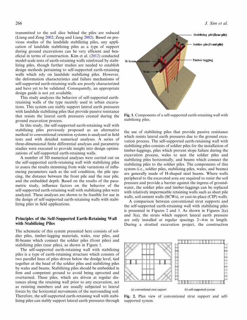
The schematic of this system presented here consists of sol-dier piles, timber-lagging materials, wales, rear piles, andH-beams which connect the soldier piles (front piles) andstabilizing piles (rear piles), as shown in Figure 1.
The self-supported earth-retaining wall with stabilizingpiles is a type of earth-retaining structure which consists oftwo parallel lines of piles driven below the dredge level, tiedtogether at the head of the soldier piles and stabilizing pilesby wales and beams. Stabilizing piles should be embedded infirm and competent ground to avoid being uprooted andoverturned. These piles, which are driven at regular dis-tances along the retaining wall prior to any excavation, actas resisting members and are usually subjected to lateralforces by the horizontal movements of the surrounding soil.Therefore, the self-supported earth-retaining wall with stabi-lizing piles can stably support lateral earth pressures through
the use of stabilizing piles that provide passive resistancewhich resists lateral earth pressures due to the ground exca-vation process. The self-supported earth-retaining wall withstabilizing piles consists of soldier piles for the installation oftimber-laggings, piles which prevent slope failure during theexcavation process, wales to seat the soldier piles andstabilizing piles horizontally, and beams which connect thestabilizing piles to the soldier piles. The components of thissystem (i.e., soldier piles, stabilizing piles, wales, and beams)are generally made of H-shaped steel beams. Where wallsperipheral to the excavated area are required to resist the soilpressure and provide a barrier against the ingress of ground-water, the soldier piles and timber-laggings can be replacedwith relatively impermeable retaining walls such as sheet pilewalls, soil cement walls (SCWs), or cast-in-place (CIP) walls.
A comparison between conventional strut supports andthe self-supported earth-retaining wall with stabilizing pilesis presented in Figures 2 and 3. As shown in Figures 2(a)and 3(a), the struts which support lateral earth pressureare only installed at regular spacings 2�4 m in length.During a strutted excavation project, the construction
Fig. 1. Components of a self-supported earth-retaining wall withstabilizing piles.
Fig. 2. Plan view of conventional strut support and self-supported system.
266 J. Sim et al.

workspace is typically limited, as can be expected. Theself-supported earth-retaining wall with stabilizing pilesallows for a larger construction workspace than thoseassociated with conventional support systems, as shownin Figures 2(b) and 3(b). This simplifies the constructionprocess given the larger workspace. Furthermore, whenusing the self-supported earth-retaining wall with stabilizingpiles, the ground excavation process takes less thancompared to that when conventional support systems areused. The amount of steel required is also reduced, makingthis process more economically efficient compared to theuse of the strut support system. However, to achieve stabilityof the self-supported earth-retaining wall with stabilizingpiles, the application of this system where the soil conditionbelow the final excavation level is relatively stiff and firm is
recommended. Moreover, for the installation of the stabiliz-ing piles, an extra area behind the retaining wall is required.
The construction sequence of the self-supported earth-retaining wall with stabilizing piles proceeds accordingto the steps shown in Figure 4. These are: (1) theinstallation of the soldier piles and the stabilizing piles;(2) the installation of the wales to connect each pile;(3) the creation of connections between the wales usingH-beams; and (4) the excavation and installation of thetimber-laggings.
Field Test
Site Condition
The self-supported earth-retaining wall with stabilizing pileswas constructed as a temporary earth-retaining wall systemin a number of underground structures in Korea. In orderto verify the performance of the self-supported earth-retaining wall with stabilizing piles, the measured data fromtwo different sites were analyzed. The main focus in thesecases was a comparative analysis of these self-supportedearth-retaining walls when used in different soil types (sandysoil and clayey soil). For these two types of cases, relevantinformation was extracted and analyzed, consideringmajor factors such as the soil properties, excavation depth,excavation-induced lateral wall movement, and bendingmoment.
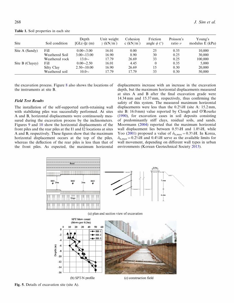
The excavation depths at the sites range from 7.6 to 8.0 m,with weathered or sedimentary soil underlying as fill materi-als. Comprehensive field and laboratory tests were carriedout on in situ soils to estimate the soil properties. The soilproperties at each site are shown in Table 1 and the StandardPenetration Test (SPT) profiles of each site are shown inFigures 5 and 6.
H-beams of H300� 300� 10� 15 mm steel sections wereused at piles and beams. Front piles and rear piles wereinstalled at a center-to-center spacing of 1.6 m. The distancebetween the front piles and the rear piles was 2.5 m, and thefront piles and rear piles penetrated to a depth of 4.0 m(¼0.5H) below the final excavation level. Timber-laggingswith thickness of 70 mm were used. The details of theself-supported earth-retaining wall used at site A and siteB are shown in Figures 5 and 6, respectively.
Instrumentation Method
The retaining wall at site A is instrumented as shown inFigure 7. Four inclinometers which measured the horizontaldisplacement were installed to a depth of 12.0 m below theground surface. As shown in Figure 7(b), one inclinometer(I1) was installed just behind the front pile and another incli-nometer (I2) was placed behind the rear pile, and 16 vibrat-ing wire strain gauges were installed on the front pile and therear pile. The bending moments acting on the instrumentedfront pile and rear pile were calculated from the readings ofthe strain gauges. All instruments were installed and initia-lized prior to the commencement of any constructionactivity and all measured data were obtained daily duringFig. 4. Construction sequence.
Fig. 3. Section view of conventional strut support andself-supported system.
Self-Supported Earth-Retaining Wall with Stabilizing Piles 267
the excavation process. Figure 8 also shows the locations ofthe instruments at site B.
Field Test Results
The installation of the self-supported earth-retaining wallwith stabilizing piles was successfully performed. At sitesA and B, horizontal displacements were continuously mea-sured during the excavation process by the inclinometers.Figures 9 and 10 show the horizontal displacements of thefront piles and the rear piles at the I1 and I2 locations at sitesA and B, respectively. These figures show that the maximumhorizontal displacement occurs at the top of the piles,whereas the deflection of the rear piles is less than that ofthe front piles. As expected, the maximum horizontal
displacements increase with an increase in the excavationdepth, but the maximum horizontal displacements measuredat sites A and B after the final excavation grade were14.34 mm and 15.37 mm, respectively, thus confirming thesafety of this system. The measured maximum horizontaldisplacements were less than the 0.2%H (site A: 15.2 mm,site B: 16.0 mm) value reported by Clough and O’Rourke(1990), for excavation cases in soil deposits consistingof predominantly stiff clays, residual soils, and sands.Moormann (2004) reported that the maximum horizontalwall displacement lies between 0.5%H and 1.0%H, whileYoo (2001) proposed a value of dh,max¼ 0.3%H. In Korea,dh,max¼ 0.2%H and 0.4%H serve as the available limits forwall movement, depending on different wall types in urbanenvironments (Korean Geotechnical Society 2013).
Fig. 5. Details of excavation site (site A).
Table 1. Soil properties in each site
Site Soil conditionDepth
[GL(-)]z (m)Unit weightc (kN=m
3
)Cohesionc (kN=m
2
)Friction
angle / (�)Poisson’s
ratio nYoung’s
modulus E (kPa)
Site A (Sandy) Fill 0.00�3.00 16.01 0.00 25 0.35 10,000Weathered Soil 3.00�13.00 16.90 8.90 30 0.25 30,000Weathered rock 13.0� 17.79 26.69 33 0.25 100,000
Site B (Clayey) Fill 0.00�2.50 16.01 4.45 0 0.35 5,000Silty Clay 2.50�10.00 16.90 26.69 15 0.30 20,000Weathered soil 10.0� 17.79 17.79 33 0.30 50,000
268 J. Sim et al.

In addition to checking the measured horizontal displace-ment, the measured strength of the piles should be com-pared to the allowable strength of the piles used toinvestigate the stability of the retaining wall system. For
sites A and B here, the allowable bending stresses of thepiles were 101.25 and 97.65 MPa, respectively. The corre-sponding bending moment profiles pertaining to the frontpile and the rear pile at sites A and B are shown in
Fig. 6. Details of excavation site (site B).
Fig. 7. Instrumentation layout (site A).
Self-Supported Earth-Retaining Wall with Stabilizing Piles 269

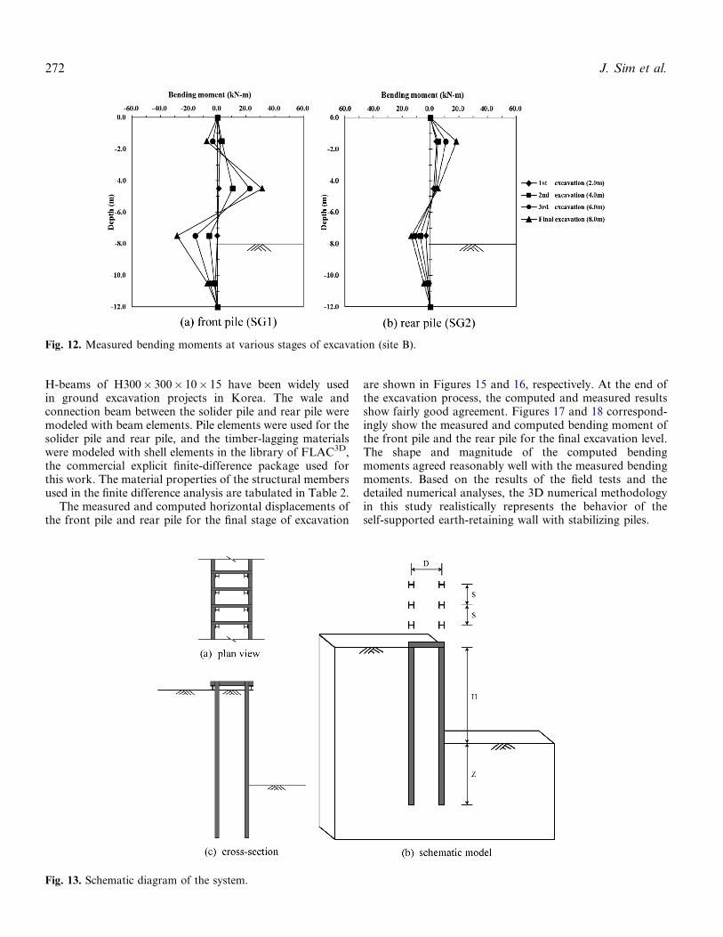
Figures 11 and 12. Instances of both positive and negativebending moment were observed on the front pile and therear pile. As shown in Figures 11 and 12, the maximumbending moment of the front pile occurs near the midpointof the piles, while that of the rear pile occurs near the top ofthe piles. Both the maximum positive and negative bendingmoment on the front pile and the rear pile increased with anincrease in the excavation depth. The average magnitude ofthe maximum bending moment that developed on the rearpile was approximately half of that which developed onthe front pile. Moreover, the shapes of the bending momentprofiles on the upper portions of the front pile and the rearpile were considerably different. The measured maximumbending stress was found to be less than the allowable bend-ing stress of the piles (site A: 46.10 MPa <101.25 MPa; siteB: 44.80 MPa <97.65 MPa).
Based on the results of the measured horizontal displace-ment and the bending moment, the self-supported earth-retaining wall with stabilizing piles was considered to havebeen successfully designed and constructed as a temporaryearth-retaining wall system.
Validation of the Numerical Analyses for Field Tests
To investigate the behavior of the self-supported earth-retaining wall with stabilizing piles in field tests, numericalanalyses with the finite difference program Fast Lagran-gian Analysis of Continua in Three Dimensions (FLAC3D)were performed (ITASCA Consulting Group 2005).FLAC3D is able to model plastic failure and flow as wellas elastic behavior. The explicit Lagrangian solutionscheme involves a large number of calculation steps, each
Fig. 8. Instrumentation layout (site B).
Fig. 9. Measured horizontal displacements at various stages of excavation (site A).
270 J. Sim et al.

progressively redistributing through the mesh the unba-lanced force resulting from changes in the stress or bound-ary displacement levels. The maximum unbalanced force isthe magnitude of the vector sum of the nodal forces for allof the nodes within the mesh. The model is considered tobe in equilibrium when the maximum unbalanced force issmall in comparison with the total applied force associatedwith stress or boundary displacement changes. If the unba-lanced force approaches a constant nonzero value, thisusually indicates that failure and plastic flow phenomenaare occurring within the model. The model is normallyapplied when the force ratio is below 1� 10�5 (i.e., theratio between the magnitude of the maximum unbalancedforce and the magnitude of the total forces applied to themesh).
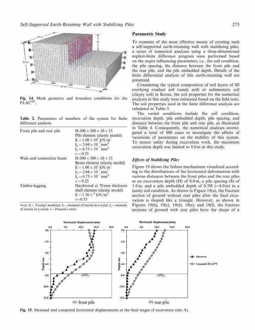
Figure 13 shows the plan view, cross-section, andschematic model of the system. Figure 14 shows the
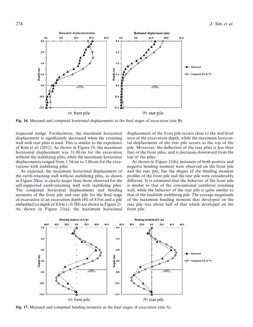
corresponding finite-difference mesh, which has 38,400 zonesand boundary conditions.
The planes y¼ 0 and y¼ 40 are allowed to move freely inthe x- and z-directions, but not in the y-direction. Similarly,the planes x¼ 0 and x¼ 40 are free to move in the y- andz-directions, but not in the x-direction. At the bottom planez¼ 0, all movements are restrained, as shown in Figure 14.A distance about 2.5 times the excavation depth wasconsidered between the excavation centerline and the leftboundary. The distances in front of and behind the wall werevaried in order to establish the effect of the location of thisboundary on the calculated behavior of the wall. It wasfound that the response of the wall became insensitivewhen this boundary was located at a distance of more than2.0 times the excavation depth from the wall face. For thesoil behavior, a linear elastic-perfectly plastic associativeMohr-Coulomb model encoded in FLAC3D is adopted.
Fig. 10. Measured horizontal displacements at various stages of excavation (site B).
Fig. 11. Measured bending moments at various stages of excavation (site A).
Self-Supported Earth-Retaining Wall with Stabilizing Piles 271
H-beams of H300� 300� 10� 15 have been widely usedin ground excavation projects in Korea. The wale andconnection beam between the solider pile and rear pile weremodeled with beam elements. Pile elements were used for thesolider pile and rear pile, and the timber-lagging materialswere modeled with shell elements in the library of FLAC3D,the commercial explicit finite-difference package used forthis work. The material properties of the structural membersused in the finite difference analysis are tabulated in Table 2.
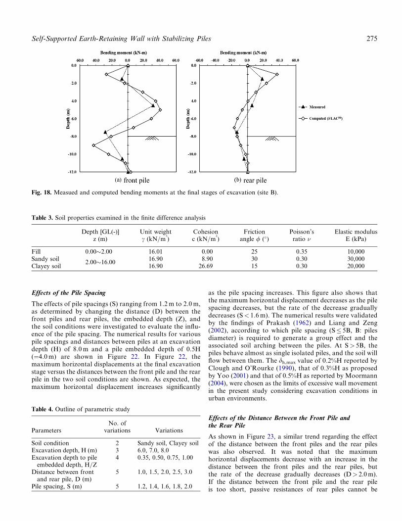
The measured and computed horizontal displacements ofthe front pile and rear pile for the final stage of excavation
are shown in Figures 15 and 16, respectively. At the end ofthe excavation process, the computed and measured resultsshow fairly good agreement. Figures 17 and 18 correspond-ingly show the measured and computed bending moment ofthe front pile and the rear pile for the final excavation level.The shape and magnitude of the computed bendingmoments agreed reasonably well with the measured bendingmoments. Based on the results of the field tests and thedetailed numerical analyses, the 3D numerical methodologyin this study realistically represents the behavior of theself-supported earth-retaining wall with stabilizing piles.
Fig. 12. Measured bending moments at various stages of excavation (site B).
Fig. 13. Schematic diagram of the system.
272 J. Sim et al.
Parametric Study
To examine of the most effective means of creating sucha self-supported earth-retaining wall with stabilizing piles,a series of numerical analyses using a three-dimensionalexplicit-finite difference program were performed basedon the major influencing parameters; i.e., the soil condition,the pile spacing, the distance between the front pile andthe rear pile, and the pile embedded depth. Details of thefinite differential analysis of this earth-retaining wall arepresented.
Considering the typical composition of soil layers of filloverlying residual soil (sandy soil) or sedimentary soil(clayey soil) in Korea, the soil properties for the numericalanalyses in this study were estimated based on the field tests.The soil properties used in the finite difference analysis aretabulated in Table 3.
The varied conditions include the soil condition,excavation depth, pile embedded depth, pile spacing, anddistance between the front pile and rear pile, as illustratedin Table 4. Consequently, the numerical analyses investi-gated a total of 600 cases to investigate the effects ofvariations of parameters on the stability of this system.To ensure safety during excavation work, the maximumexcavation depth was limited to 8.0 m in this study.
Effects of Stabilizing Piles
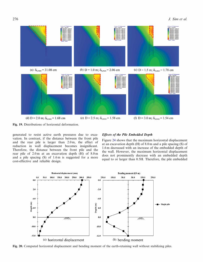
Figure 19 shows the failure mechanisms visualized accord-ing to the distributions of the horizontal deformation withvarious distances between the front piles and the rear pilesat an excavation depth (H) of 8.0 m, a pile spacing (S) of1.6 m, and a pile embedded depth of 0.5H (¼4.0 m) in asandy soil condition. As shown in Figure 19(a), the fracturesection of ground without rear piles after the final exca-vation is shaped like a triangle. However, as shown inFigures 19(b), 19(c), 19(d), 19(e), and 19(f), the fracturesections of ground with rear piles have the shape of a
Fig. 14. Mesh geometry and boundary conditions for theFLAC3D.
Table 2. Parameters of members of the system for finitedifference analysis
Front pile and rear pile H-300� 300� 10� 15Pile element (elastic model)E¼ 1.00� 10
8
kN=m2
Ix¼ 2.04� 10�4
mm4
Iy¼ 6.75� 10�5
mm4
n¼ 0.25Wale and connection beam H-300� 300� 10� 15
Beam element (elastic model)E¼ 1.00� 10
8
kN=m2
Ix¼ 2.04� 10�4
mm4
Iy¼ 6.75� 10�5
mm4
n¼ 0.25Timber-lagging Hardwood at 70 mm thickness
shell element (elastic model)E¼ 1.50� 4 kN=m2
n¼0.35
Note: E ¼ Young’s modulus; Ix¼moment of inertia in x-axial; Iy¼momentof inertia in y-axial; n¼Poisson’s ratio.
Fig. 15. Measued and computed horizontal displacements at the final stages of excavation (site A).
Self-Supported Earth-Retaining Wall with Stabilizing Piles 273
trapezoid wedge. Furthermore, the maximum horizontaldisplacement is significantly decreased when the retainingwall with rear piles is used. This is similar to the experienceof Kim et al. (2012). As shown in Figure 19, the maximumhorizontal displacement was 31.08 cm for the excavationwithout the stabilizing piles, while the maximum horizontaldisplacements ranged from 1.54 cm to 2.06 cm for the exca-vations with stabilizing piles.
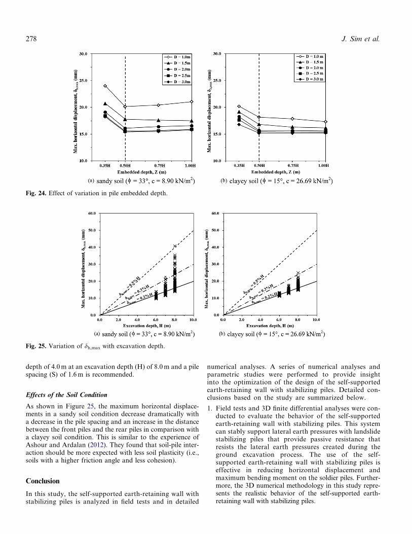
As expected, the maximum horizontal displacement ofthe earth-retaining wall without stabilizing piles, as shownin Figure 20(a), is clearly larger than those observed for theself-supported earth-retaining wall with stabilizing piles.The computed horizontal displacements and bendingmoments of the front pile and rear pile for the final stageof excavation at an excavation depth (H) of 8.0 m and a pileembedded (z) depth of 4.0 m (¼0.5H) are shown in Figure 21.As shown in Figure 21(a), the maximum horizontal
displacement of the front pile occurs close to the mid-levelarea of the excavation depth, while the maximum horizon-tal displacement of the rear pile occurs at the top of thepile. Moreover, the deflection of the rear piles is less thanthat of the front piles, and it decreases downward from thetop of the piles.
As shown in Figure 21(b), instances of both positive andnegative bending moment were observed on the front pileand the rear pile, but the shapes of the bending momentprofiles of the front pile and the rear pile were considerablydifferent. It is estimated that the behavior of the front pileis similar to that of the conventional cantilever retainingwall, while the behavior of the rear pile is quite similar tothat of the landslide stabilizing pile. The average magnitudeof the maximum bending moment that developed on therear pile was about half of that which developed on thefront pile.
Fig. 16. Measued and computed horizontal displacements at the final stages of excavation (site B).
Fig. 17. Measued and computed bending moments at the final stages of excavation (site A).
274 J. Sim et al.
Effects of the Pile Spacing
The effects of pile spacings (S) ranging from 1.2 m to 2.0 m,as determined by changing the distance (D) between thefront piles and rear piles, the embedded depth (Z), andthe soil conditions were investigated to evaluate the influ-ence of the pile spacing. The numerical results for variouspile spacings and distances between piles at an excavationdepth (H) of 8.0 m and a pile embedded depth of 0.5H(¼4.0 m) are shown in Figure 22. In Figure 22, themaximum horizontal displacements at the final excavationstage versus the distances between the front pile and the rearpile in the two soil conditions are shown. As expected, themaximum horizontal displacement increases significantly
as the pile spacing increases. This figure also shows thatthe maximum horizontal displacement decreases as the pilespacing decreases, but the rate of the decrease graduallydecreases (S< 1.6 m). The numerical results were validatedby the findings of Prakash (1962) and Liang and Zeng(2002), according to which pile spacing (S� 5B, B: pilesdiameter) is required to generate a group effect and theassociated soil arching between the piles. At S> 5B, thepiles behave almost as single isolated piles, and the soil willflow between them. The dh,max value of 0.2%H reported byClough and O’Rourke (1990), that of 0.3%H as proposedby Yoo (2001) and that of 0.5%H as reported by Moormann(2004), were chosen as the limits of excessive wall movementin the present study considering excavation conditions inurban environments.
Effects of the Distance Between the Front Pile andthe Rear Pile
As shown in Figure 23, a similar trend regarding the effectof the distance between the front piles and the rear pileswas also observed. It was noted that the maximumhorizontal displacements decrease with an increase in thedistance between the front piles and the rear piles, butthe rate of the decrease gradually decreases (D> 2.0 m).If the distance between the front pile and the rear pileis too short, passive resistances of rear piles cannot be
Table 3. Soil properties examined in the finite difference analysis
Depth [GL(-)]z (m)
Unit weightc (kN=m
3
)Cohesionc (kN=m
2
)Friction
angle / (�)Poisson’s
ratio nElastic modulus
E (kPa)
Fill 0.00�2.00 16.01 0.00 25 0.35 10,000Sandy soil
2.00�16.0016.90 8.90 30 0.30 30,000
Clayey soil 16.90 26.69 15 0.30 20,000
Table 4. Outline of parametric study
ParametersNo. of
variations Variations
Soil condition 2 Sandy soil, Clayey soilExcavation depth, H (m) 3 6.0, 7.0, 8.0Excavation depth to pile
embedded depth, H=Z4 0.35, 0.50, 0.75, 1.00
Distance between frontand rear pile, D (m)
5 1.0, 1.5, 2.0, 2.5, 3.0
Pile spacing, S (m) 5 1.2, 1.4, 1.6, 1.8, 2.0
Fig. 18. Measued and computed bending moments at the final stages of excavation (site B).
Self-Supported Earth-Retaining Wall with Stabilizing Piles 275
generated to resist active earth pressures due to exca-vation. In contrast, if the distance between the front pileand the rear pile is larger than 2.0 m, the effect ofreduction in wall displacement becomes insignificant.Therefore, the distance between the front pile and therear pile of 2.0 m at an excavation depth (H) of 8.0 mand a pile spacing (S) of 1.6 m is suggested for a morecost-effective and reliable design.
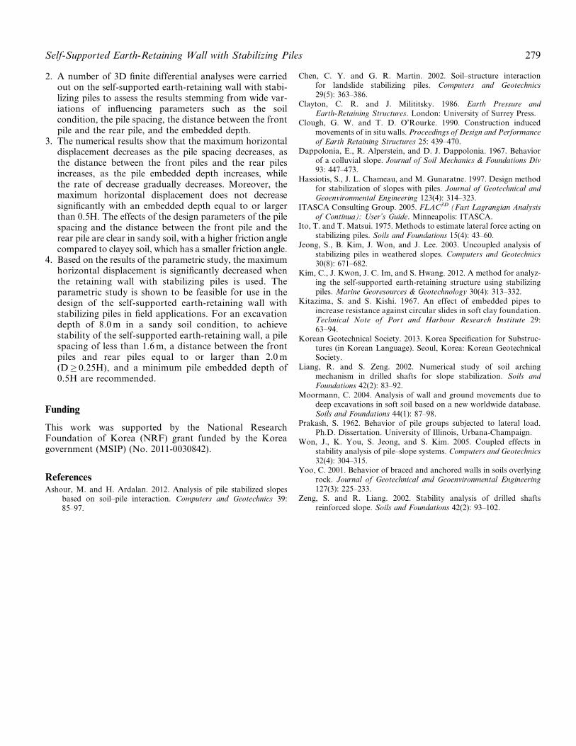
Effects of the Pile Embedded Depth
Figure 24 shows that the maximum horizontal displacementat an excavation depth (H) of 8.0 m and a pile spacing (S) of1.6 m decreased with an increase of the embedded depth ofthe wall. However, the maximum horizontal displacementdoes not prominently decrease with an embedded depthequal to or larger than 0.5H. Therefore, the pile embedded
Fig. 19. Distributions of horizontal deformation.
Fig. 20. Computed horizontal displacement and bending moment of the earth-retaining wall without stabilizing piles.
276 J. Sim et al.

Fig. 21. Computed horizontal displacement and bending moment of the self-supported earth-retaining wall with stabilizing piles.
Fig. 22. Effect of variation in pile spacing.
Fig. 23. Effect of variation in distance between the front pile and the rear pile.
Self-Supported Earth-Retaining Wall with Stabilizing Piles 277
depth of 4.0 m at an excavation depth (H) of 8.0 m and a pilespacing (S) of 1.6 m is recommended.
Effects of the Soil Condition
As shown in Figure 25, the maximum horizontal displace-ments in a sandy soil condition decrease dramatically witha decrease in the pile spacing and an increase in the distancebetween the front piles and the rear piles in comparison witha clayey soil condition. This is similar to the experience ofAshour and Ardalan (2012). They found that soil-pile inter-action should be more expected with less soil plasticity (i.e.,soils with a higher friction angle and less cohesion).
Conclusion
In this study, the self-supported earth-retaining wall withstabilizing piles is analyzed in field tests and in detailed
numerical analyses. A series of numerical analyses andparametric studies were performed to provide insightinto the optimization of the design of the self-supportedearth-retaining wall with stabilizing piles. Detailed con-clusions based on the study are summarized below.
1. Field tests and 3D finite differential analyses were con-ducted to evaluate the behavior of the self-supportedearth-retaining wall with stabilizing piles. This systemcan stably support lateral earth pressures with landslidestabilizing piles that provide passive resistance thatresists the lateral earth pressures created during theground excavation process. The use of the self-supported earth-retaining wall with stabilizing piles iseffective in reducing horizontal displacement andmaximum bending moment on the soldier piles. Further-more, the 3D numerical methodology in this study repre-sents the realistic behavior of the self-supported earth-retaining wall with stabilizing piles.
Fig. 25. Variation of dh,max with excavation depth.
Fig. 24. Effect of variation in pile embedded depth.
278 J. Sim et al.
2. A number of 3D finite differential analyses were carriedout on the self-supported earth-retaining wall with stabi-lizing piles to assess the results stemming from wide var-iations of influencing parameters such as the soilcondition, the pile spacing, the distance between the frontpile and the rear pile, and the embedded depth.
3. The numerical results show that the maximum horizontaldisplacement decreases as the pile spacing decreases, asthe distance between the front piles and the rear pilesincreases, as the pile embedded depth increases, whilethe rate of decrease gradually decreases. Moreover, themaximum horizontal displacement does not decreasesignificantly with an embedded depth equal to or largerthan 0.5H. The effects of the design parameters of the pilespacing and the distance between the front pile and therear pile are clear in sandy soil, with a higher friction anglecompared to clayey soil, which has a smaller friction angle.
4. Based on the results of the parametric study, the maximumhorizontal displacement is significantly decreased whenthe retaining wall with stabilizing piles is used. Theparametric study is shown to be feasible for use in thedesign of the self-supported earth-retaining wall withstabilizing piles in field applications. For an excavationdepth of 8.0 m in a sandy soil condition, to achievestability of the self-supported earth-retaining wall, a pilespacing of less than 1.6 m, a distance between the frontpiles and rear piles equal to or larger than 2.0 m(D� 0.25H), and a minimum pile embedded depth of0.5H are recommended.
Funding
This work was supported by the National ResearchFoundation of Korea (NRF) grant funded by the Koreagovernment (MSIP) (No. 2011-0030842).
ReferencesAshour, M. and H. Ardalan. 2012. Analysis of pile stabilized slopes
based on soil–pile interaction. Computers and Geotechnics 39:85–97.
Chen, C. Y. and G. R. Martin. 2002. Soil–structure interactionfor landslide stabilizing piles. Computers and Geotechnics29(5): 363–386.
Clayton, C. R. and J. Milititsky. 1986. Earth Pressure andEarth-Retaining Structures. London: University of Surrey Press.
Clough, G. W. and T. D. O’Rourke. 1990. Construction inducedmovements of in situ walls. Proceedings of Design and Performanceof Earth Retaining Structures 25: 439–470.
Dappolonia, E., R. Alperstein, and D. J. Dappolonia. 1967. Behaviorof a colluvial slope. Journal of Soil Mechanics & Foundations Div93: 447–473.
Hassiotis, S., J. L. Chameau, and M. Gunaratne. 1997. Design methodfor stabilization of slopes with piles. Journal of Geotechnical andGeoenvironmental Engineering 123(4): 314–323.
ITASCA Consulting Group. 2005. FLAC3D (Fast Lagrangian Analysisof Continua): User’s Guide. Minneapolis: ITASCA.
Ito, T. and T. Matsui. 1975. Methods to estimate lateral force acting onstabilizing piles. Soils and Foundations 15(4): 43–60.
Jeong, S., B. Kim, J. Won, and J. Lee. 2003. Uncoupled analysis ofstabilizing piles in weathered slopes. Computers and Geotechnics30(8): 671–682.
Kim, C., J. Kwon, J. C. Im, and S. Hwang. 2012. A method for analyz-ing the self-supported earth-retaining structure using stabilizingpiles. Marine Georesources & Geotechnology 30(4): 313–332.
Kitazima, S. and S. Kishi. 1967. An effect of embedded pipes toincrease resistance against circular slides in soft clay foundation.Technical Note of Port and Harbour Research Institute 29:63–94.
Korean Geotechnical Society. 2013. Korea Specification for Substruc-tures (in Korean Language). Seoul, Korea: Korean GeotechnicalSociety.
Liang, R. and S. Zeng. 2002. Numerical study of soil archingmechanism in drilled shafts for slope stabilization. Soils andFoundations 42(2): 83–92.
Moormann, C. 2004. Analysis of wall and ground movements due todeep excavations in soft soil based on a new worldwide database.Soils and Foundations 44(1): 87–98.
Prakash, S. 1962. Behavior of pile groups subjected to lateral load.Ph.D. Dissertation. University of Illinois, Urbana-Champaign.
Won, J., K. You, S. Jeong, and S. Kim. 2005. Coupled effects instability analysis of pile–slope systems. Computers and Geotechnics32(4): 304–315.
Yoo, C. 2001. Behavior of braced and anchored walls in soils overlyingrock. Journal of Geotechnical and Geoenvironmental Engineering127(3): 225–233.
Zeng, S. and R. Liang. 2002. Stability analysis of drilled shaftsreinforced slope. Soils and Foundations 42(2): 93–102.
Self-Supported Earth-Retaining Wall with Stabilizing Piles 279