self-synchronous vibration testing mechanism a major qualifying project report · 2008-02-08 ·...
TRANSCRIPT

Project Number: ___ECC-C007___
Self-Synchronous Vibration Testing Mechanism
A Major Qualifying Project Report
Submitted to the Faculty
Of the
WORCESTER POLYTECHNIC INSTITUTE
In partial fulfillment of the requirements for the
Degree of Bachelor of Science
By
________________________ Bryce J. Vander Poel
________________________
Hisham Al-Beik
Date: August 22, 2007
Approved:
__________________________ Professor Eben C. Cobb
__________________________ Professor Mikhail Dimentberg

ii
Abstract This project was created to demonstrate the phenomenon known as self-synchronization using motor-driven, unbalanced rotors mounted on a spring-mounted base. A mechanism resembling that used by scientists who first studied the phenomenon was constructed and used to successfully reproduce the desired effect. Some modifications, including the removal of key components, were deemed necessary to obtain satisfactory results.
iii
TABLE OF CONTENTS Abstract ii Table of Contents iii Table of Figures iv 1. Introduction 1 2. Background 3
2.1 Self-synchronization 3 2.2 Task Specifications 6
3. Theoretical Design 7 3.1 Materials 8 3.1.1 Steel 8 3.1.2 Aluminum 8 3.1.3 Pine 8 3.1.4 Fiberboard 8 3.2 Material Comparison 9 4. Physical Design and Manufacturing 10 4.1 Component Selection 4.1.1 Electric Motors 10 4.1.2 80/20 Framing System 14 4.1.3 Springs 16 4.2 Manufacturing 4.2.1 Leaf Springs 16 4.2.2 Shafts 16 4.2.3 Unbalanced Weights 16 4.2.4 Vibrator Platform 17 4.2.5 Platform Frame 17 4.2.6 Switch Mount 17 4.2.7 Leaf Spring Mount 20 4.2.8 Base 20 5. Testing and Results 22 6. Conclusions Recommendations 24 Bibliography 26 Appendix: Component Specifications 27

iv
TABLE OF FIGURES Figure 1 - Self-Synchronization Mechanism ...................................................................... 2 Figure 2 - Mekhanobr rig showing three unbalanced rotors connected by a rigid vibrating pipe. ..................................................................................................................................... 5 Figure 3 - Closeup of the motors and unbalanced shafts mounted on the vibrating platform. ............................................................................................................................ 13 Figure 4 - Computer fan using a brushless-DC motor was modified for the use of this project. .............................................................................................................................. 13 Figure 5 - H-frame track for leaf springs mount. .............................................................. 15 Figure 6 - Another view of the H-frame. .......................................................................... 15 Figure 9 - A mount was made to place the switches that controlled which motors to provide power to or which to cut power to. ....................... Error! Bookmark not defined. Figure 7 - Leaf springs bolted on mount. .......................................................................... 21 Figure 8 - Another view of leaf springs and mount. ......................................................... 21
1
1: Introduction
The purpose of the design to maintain rotation of unpowered shafts through
vibration was to design and manufacture a mechanism that demonstrates the self
synchronization phenomenon.
The goal of the project was to design and manufacture a mechanism that would
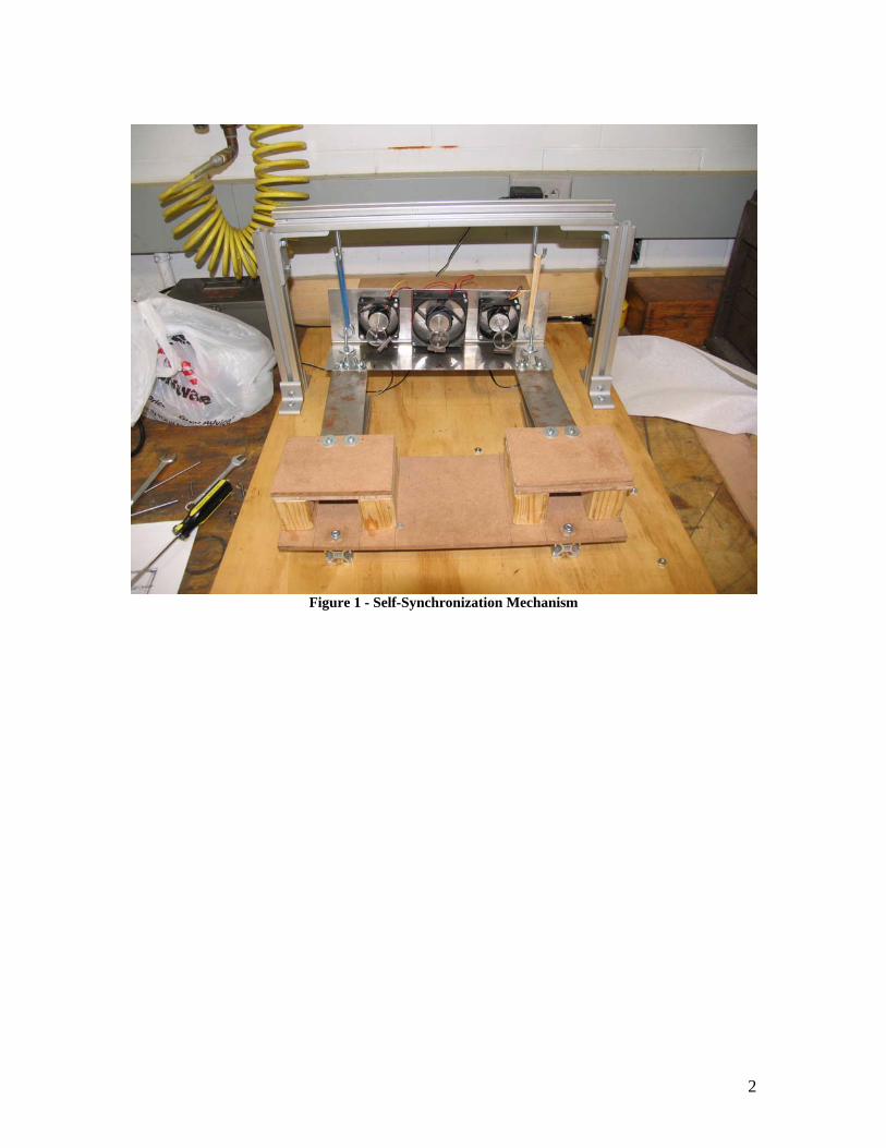
demonstrate self-synchronization of unbalanced shafts through vibration. Figure 1 shows
the completed mechanism with leaf springs attached.
The design project began with an attempt to replicate Mekhanobr’s design but
replacing the rubber shafts with metal leaf springs to make the vibrating part move in
only one dimension. Throughout manufacturing, building and testing, some components
were replaced due to financial constraints or due to time constraints. The design similar
to Mekhanobr’s rig with its alterations was tested and failed due to some choices of
components that there was no knowing of how it may affect final results. After observing
the reasons why our first design failed, a different design was concocted on the spot and
rebuilding was made in less than a day. With the assembly of the final design and the test
run, the new design was successful in achieving the main goal of the project;
demonstrating self-synchronizing mechanisms.
2
Figure 1 - Self-Synchronization Mechanism
3
2: Background
The Major Qualifying Project (MQP) design concept was based on a mechanism
created and tested at the Mekhanobr Institute in St. Petersburg, the site of the first
observation and experimentation of self-synchronization in unbalanced rotors. The use of
self-synchronization of unbalanced rotors has led to hundreds of designs that utilize
vibration as a primary form of operation, such as conveyers, screens, and crushers
(Blekhman, 2000.)
2.1 Self-Synchronization
The term self-synchronization refers to a phenomenon caused by vibrations in
unbalanced rotors. The first recorded observation of this phenomenon was made by
Christian Huygens sometime in the late 1600s. Huygens hung two pendulum clocks from
the beam of a boat and discovered that, while the clocks had previously run at different
rates, their pendulums eventually began to swing in synch and would tend to return to this
manner when one or both pendulums were disturbed. Huygens determined that this
phenomenon was due to the motions of the beam, which transmitted the vibrations
created by the pendulums from one clock to the other, forcing them to oscillate in synch
(Blekhman, 1988.)
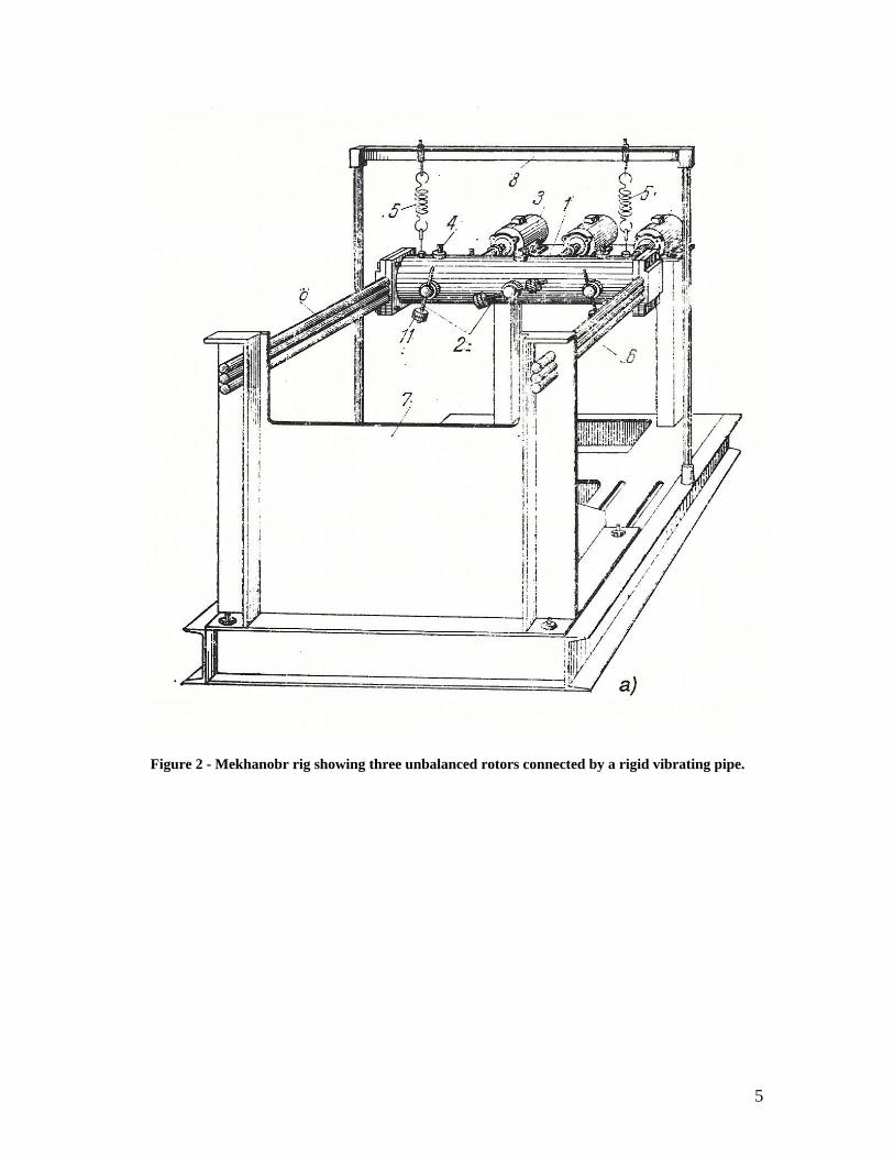
It wasn’t until 1947 that the synchronization phenomenon for mechanical
unbalanced vibro-exciters was discovered during a research project led by D.A. Pliss in
the Mekhanobr Institute. When two unbalanced rotors driven by separate induction
motors were mounted side-by-side on a fixed platform, they invariably ran at different
angular velocities due to uncontrollable differences in the construction of the motors.
However, when these same systems were mounted together on a vibrating foundation, it
was discovered that they would run at an average velocity and in synchronous motion.
Furthermore, the rotors would tend to maintain this behavior even when the power to one
motor was cut off, as it happened when the power supply cable to one of the motors was
accidentally severed but not discovered for a number of hours, since the rotors continued
to spin in synchronous motion. Figure 2 is a drawing of the three-shaft mechanism
created by researchers at the Mekhanobr (Blekhman, 1988.)

4
Synchronization can be observed in many everyday events. For example, humans
walking side by side tend to walk “in step” with one another after a short time, applause
from a large audience tends to transform into more or less a “single” clap, and wing
strokes of birds in a flock will synchronize, as will fin strokes in schools of fish and
flashes produced by fireflies.
5
Figure 2 - Mekhanobr rig showing three unbalanced rotors connected by a rigid vibrating pipe.
6
2.2 Task Specifications
• The finished mechanism should be sized to allow for easy transportation
• The mechanism should be stable and safe to operate.
• The mechanism should demonstrate the self-synchronization phenomenon.
• The mechanism should utilize three motors driving unbalanced rotors.
• The motors must be brushless and allow for resistance-free back-drive.
• The motors should be powered from a standard wall outlet.
• The design should allow for the removal of the leaf springs from the vibrating
platform.
• Overall cost should not be more than $100.
7
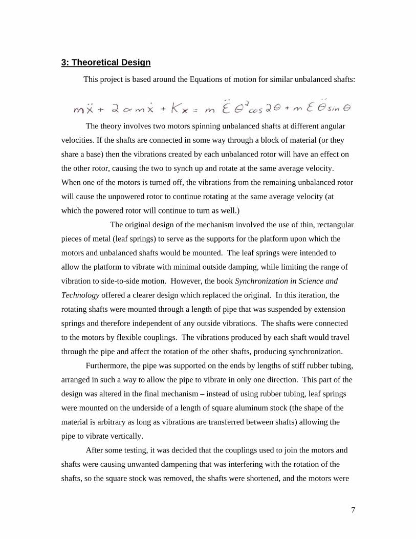
3: Theoretical Design
This project is based around the Equations of motion for similar unbalanced shafts:
The theory involves two motors spinning unbalanced shafts at different angular
velocities. If the shafts are connected in some way through a block of material (or they
share a base) then the vibrations created by each unbalanced rotor will have an effect on
the other rotor, causing the two to synch up and rotate at the same average velocity.
When one of the motors is turned off, the vibrations from the remaining unbalanced rotor
will cause the unpowered rotor to continue rotating at the same average velocity (at
which the powered rotor will continue to turn as well.)
The original design of the mechanism involved the use of thin, rectangular
pieces of metal (leaf springs) to serve as the supports for the platform upon which the
motors and unbalanced shafts would be mounted. The leaf springs were intended to
allow the platform to vibrate with minimal outside damping, while limiting the range of
vibration to side-to-side motion. However, the book Synchronization in Science and
Technology offered a clearer design which replaced the original. In this iteration, the
rotating shafts were mounted through a length of pipe that was suspended by extension
springs and therefore independent of any outside vibrations. The shafts were connected
to the motors by flexible couplings. The vibrations produced by each shaft would travel
through the pipe and affect the rotation of the other shafts, producing synchronization.
Furthermore, the pipe was supported on the ends by lengths of stiff rubber tubing,
arranged in such a way to allow the pipe to vibrate in only one direction. This part of the
design was altered in the final mechanism – instead of using rubber tubing, leaf springs
were mounted on the underside of a length of square aluminum stock (the shape of the
material is arbitrary as long as vibrations are transferred between shafts) allowing the
pipe to vibrate vertically.
After some testing, it was decided that the couplings used to join the motors and
shafts were causing unwanted dampening that was interfering with the rotation of the
shafts, so the square stock was removed, the shafts were shortened, and the motors were
8
moved onto a platform that was suspended in place of the pipe. This way, no flexible
couplings were necessary and the shafts could be cut to much shorter lengths, reducing
any flex that occurred when rotating.
3.1 Materials
Normally, materials would be chosen with attention paid to weight and cost. For
this project, the majority of materials used were obtained at no cost from the Higgins
Labs machine shop, nullifying the issue of cost. Furthermore, weight was not an issue
where most of these materials were involved, the exception being the weights on the ends
of the rotors.
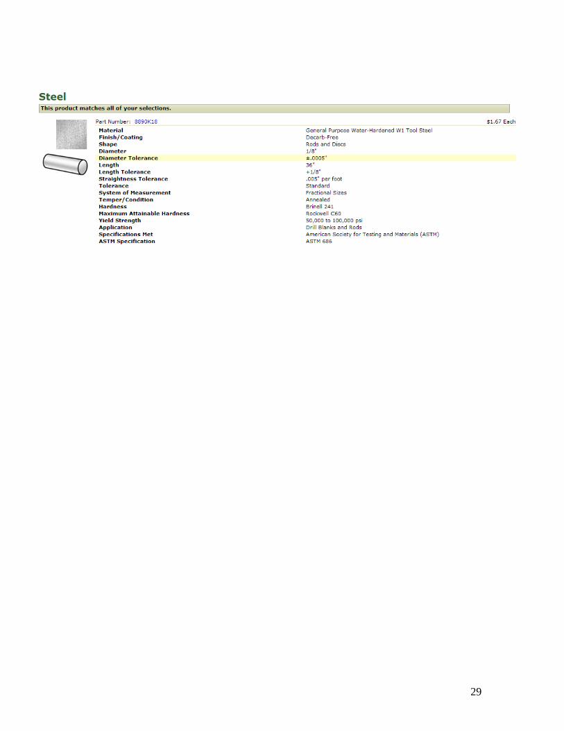
3.1.1 Steel
Steel has excellent strength and hardness, and is relatively inexpensive. However,
it is heavy, limiting its use where weight is an issue.
3.1.2 Aluminum
Aluminum is relatively lightweight and, in most instances, possesses sufficient
strength for the purposes of this mechanism.
3.1.3 Pine
Pine is lightweight and easy to manipulate, as well as very cheap and easy to
obtain, and suits the requirements of this project well.
3.1.4 Fiberboard
Like pine, fiberboard is easy to obtain and machine, and is very
inexpensive. It was used as a flat mounting surface for both the motors and the leaf
springs, and is more than strong enough to support any stresses that may occur.

9
3.2 Material Comparison
As previously stated, choice of materials was only limited by availability. The
design of the mechanism did not present any requirements that could not be met with the
available resources.
10
4: Physical Design and Manufacturing
Most materials were obtained from the machine shop located in Higgins Labs, at
no cost. Other components were purchased from different vendors. Motors were obtained
from Jameco Electrical Company.
4.1 Component Selection
Since most components don’t have much effect on the system, but rather are more
of mounts and supports. We used whatever was available in the machine shop to reduce
the cost of building the mechanism. Specific selections of components are described
below.
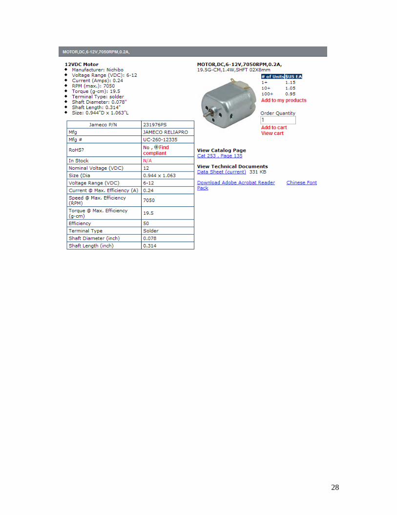
4.1.1 Electric Motors
Choosing proper electrical motors was crucial to the mechanism. Of the many
different types of motors that were available, choices were limited to the few types that
would meet the specifications of the design, which included rotational velocity (above
2000 RPM) and minimal resistance when back driven. The different types considered
were regular DC-Motors, DC-brushless motors, and AC induction motors.
Regular DC motors were considered mainly due to their low cost. These motors
would allow some back-drive but with some resistance. Regular DC-motors use a
commutator that is mounted onto the armature (rotating shaft) that would bring electrical
current to an iron core with wire coils wound around it to induce electromagnetic field
which, with the help of a permanent magnet mounted in the casing of the motor, would
create an EMF force that would rotate the armature. The commutator is connected to
outside electrical source by means of a brush. This brush provided the most resistance to
the armature to being back driven.
In addition to the price, this motor would also create an electrical current when
the shaft is driven externally. This would have helped in the analysis of the design and
calculation of power conversions to easily calculate power losses. Also, the speed of the
motor could be controlled simply by controlling the supply’s current or voltage.
Brushless-DC motors were considered because they had very low resistance to
being back-driven. Usually used on computer fans, these motors provided more than
11
enough speed for the project’s purposes and extremely low resistance to being back-
driven. These motors operate differently than the regular DC motors. Unlike the regular
DC-motors, the permanent magnets are built right onto the armature, with the steel core
and coil built onto the stationary part of the motor. The armature is simply the permanent
magnet held together by a molded plastic that is mounted onto a shaft that is kept in place
by rotational ball bearings. The only resistance felt when turning the armature by hand
was the magnet’s pull on the steel core, which was too small to affect the mechanism.
However, these specific types of motors operate by converting DC current into
quick pulses of electrical current with the use of internal circuitry, causing the armature
to move at a single speed. Varying the speed of the motor was not an option.
The third and last choice of motors were the AC-induction motors. These motors
were the type suggested by Blekhman in Synchronization, in an attempt to reproduce the
experiment designed at the Mekhanobr. AC induction motors provide the least resistance
to back-drive, mainly because the armature is simply freely rotating with no connection
to the stationary part of the motor other than bearings - not unlike the DC-brushless
motor. However, instead of a permanent magnet, coils are used to create a changing
magnetic field on the stationary part, which also in turn induces current onto small wire
loops built onto the armature.
With no current and voltage supplied to the motor, there is even less resistance
than found in a brushless-DC motor. In addition, this motor’s speed can be controlled
simply by creating a controller that can alter the power source’s frequency. However, due
to the operational method of this motor, directly measuring rotational speed from
synchronization is not possible, since there will be no current induced from armature’s
rotation.
The induction motor was not considered further due to prices of motors and
controllers being beyond the budget of this project. The first two types of motors were
tested, however. The brushed DC-motor proved to provide too much resistance to the
mechanism, causing all rotors to simply stop whenever their corresponding motors were
turned off.
In order to use the brushless-DC motors, the motor mounts required modification.
With that came a whole new concept of mounting the motors onto the vibrating part of
12
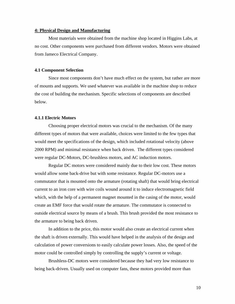
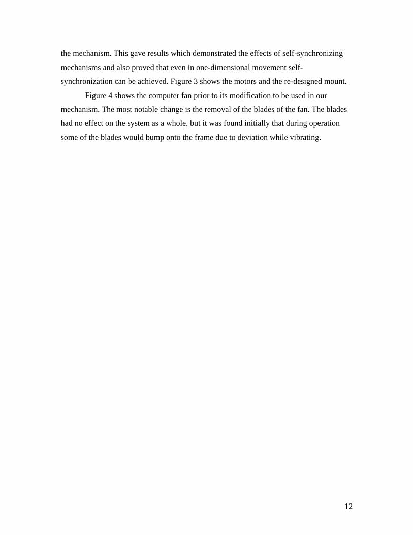
the mechanism. This gave results which demonstrated the effects of self-synchronizing
mechanisms and also proved that even in one-dimensional movement self-
synchronization can be achieved. Figure 3 shows the motors and the re-designed mount.
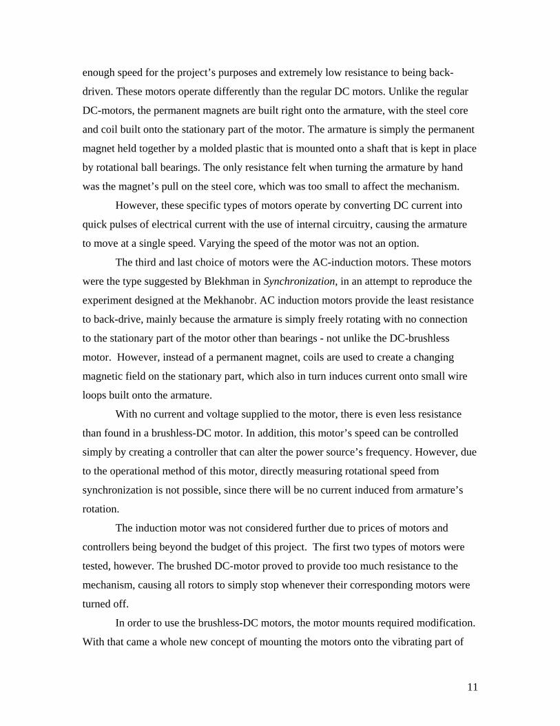
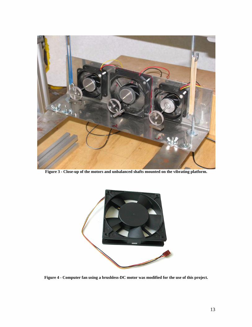
Figure 4 shows the computer fan prior to its modification to be used in our
mechanism. The most notable change is the removal of the blades of the fan. The blades
had no effect on the system as a whole, but it was found initially that during operation
some of the blades would bump onto the frame due to deviation while vibrating.
13
Figure 3 - Close-up of the motors and unbalanced shafts mounted on the vibrating platform.
Figure 4 - Computer fan using a brushless-DC motor was modified for the use of this project.
14
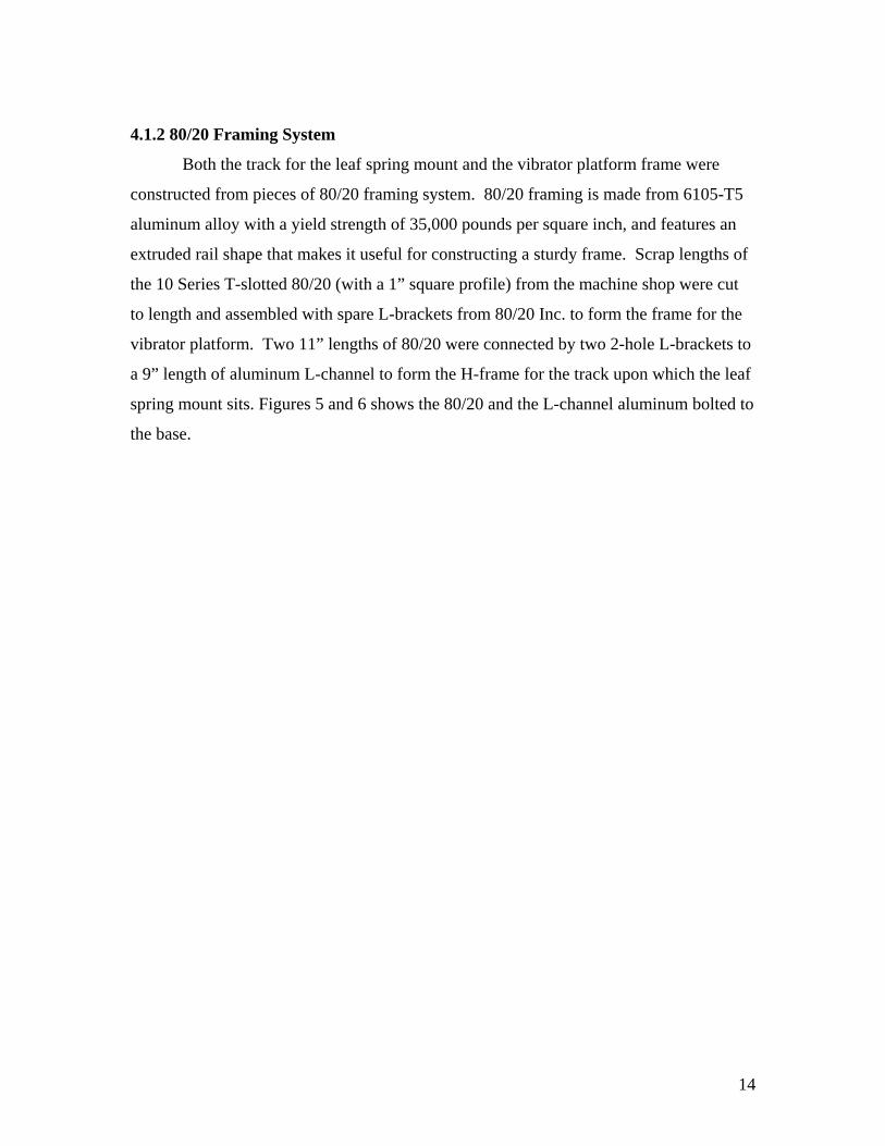
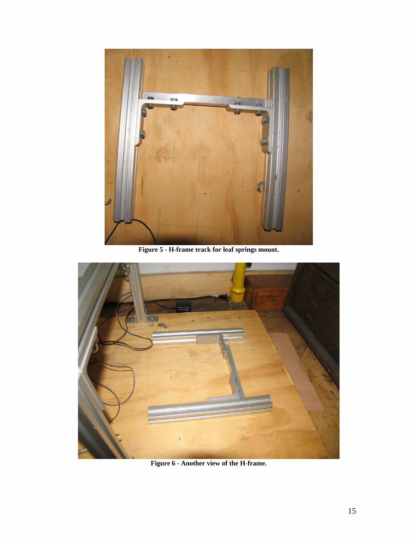
4.1.2 80/20 Framing System
Both the track for the leaf spring mount and the vibrator platform frame were
constructed from pieces of 80/20 framing system. 80/20 framing is made from 6105-T5
aluminum alloy with a yield strength of 35,000 pounds per square inch, and features an
extruded rail shape that makes it useful for constructing a sturdy frame. Scrap lengths of
the 10 Series T-slotted 80/20 (with a 1” square profile) from the machine shop were cut
to length and assembled with spare L-brackets from 80/20 Inc. to form the frame for the
vibrator platform. Two 11” lengths of 80/20 were connected by two 2-hole L-brackets to
a 9” length of aluminum L-channel to form the H-frame for the track upon which the leaf
spring mount sits. Figures 5 and 6 shows the 80/20 and the L-channel aluminum bolted to
the base.
15
Figure 5 - H-frame track for leaf springs mount.
Figure 6 - Another view of the H-frame.
16
4.1.3 Springs
Originally, springs were selected to support the square aluminum stock, but were
later replaced with rubber bands to support the vibrator platform. The elasticity of the
bands was deemed unimportant as long as they held the platform clear of the base. The
rubber bands actually seemed to work much better than the springs, since they
contributed almost no damping to the mechanism, whereas the springs seemed to have a
small effect.
4.2 Manufacturing
All manufactured components were created in the machine shop located in
Higgins Labs, and most material (unless noted otherwise) was obtained from the supply
closet in the machine shop. Machines used included a three-axis milling machine, drill
press, handheld jig saw, band saw, and various small hand tools.
4.2.1 Leaf Springs
The leaf springs were machined out of 22GA welding steel (approximately 1/40th
of an inch thick) and provided the necessary flexibility and strength to support the
vibrator platform with minimal dampening.
4.2.2 Shafts
The rotating shafts were machined out of a 36 inch length of steel rod, 3
millimeters in diameter. The diameter was arbitrarily chosen, taking into account size
considerations for the motors and overall mechanism.
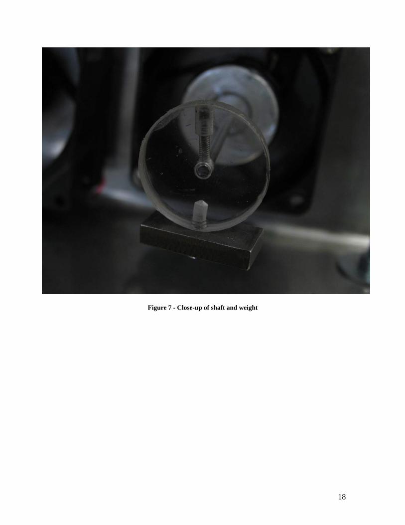
4.2.3 Unbalanced Weights
The unbalanced weights were machined out of pieces of scrap steel obtained from
the Higgins Labs machine shop. Sizes varying by a few millimeters were manufactured
and then tested to find the weights that produced the best results. Figure 7 shows a closer
view of one of shafts with the weight attached.
17
4.2.4 Vibrator Platform
The vibrator platform consisted of a 6.5”x13” piece of sheet steel, which was bent
into two sections: the bottom, which was 3”x13”; and the back, which was 3.5”x13”, and
was the surface to which the motors were mounted.
4.2.5 Platform Frame
80/20 was used to build the frame that would support the vibrator platform and
isolate it from any outside vibrations. Easy to manipulate and construct, proper T-nuts
(used to attach lengths of 80/20) were not available, but hex nuts and button-head bolts
were substituted with satisfactory results.
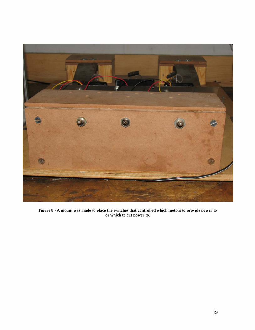
4.2.6 Switch Mount
Originally intended to be the mounting platform for the motors, it is constructed
out of two 4” lengths of 2’x4’ (which serve as the supports), a 4”x12” piece of fiberboard
on which the switches are mounted, and a 3.5”x12” piece of fiberboard attached to the
tops of the supports. Figure 8 shows the switch mount.
18
Figure 7 - Close-up of shaft and weight
19
Figure 8 - A mount was made to place the switches that controlled which motors to provide power to
or which to cut power to.
20
4.2.7 Leaf Spring Mount
The leaf spring mount was constructed out of a fiberboard base (5.5”x15”) upon
which were mounted four 2” lengths of 2”x4”, each pair of which served as supports for a
3.5”x5” piece of fiberboard where the leaf springs were attached. Each leaf spring was
sandwiched between its base and a second piece of fiberboard to equalize above- and
below-plane flexing when the mechanism was in operation. Shown in Figures 9 and 10
are the leaf springs bolted into the mount.
4.2.8 Base
The base upon which the entire system was built was a 21.5”x25” piece of
plywood. Holes were drilled to mount the various components of the mechanism: the
vibrator frame, the leaf spring track, and the switch mount supports.

21
Figure 9 - Leaf springs bolted on mount.
Figure 10 - Another view of leaf springs and mount.
22
5: Testing and Results
Once construction of the first design iteration was complete, testing began on the
mechanism. After a number of runs, the design was clearly not working properly. It was
determined that the rotors would not synch up because of too much vibration.
Furthermore, the motors offered too much resistance to allow the unpowered rotors to
spin freely. The flexible spring couplings between the motors and the shafts were
affecting shaft rotation as well – the shafts were flexing too much and rotational velocity
was not being properly transferred from the motor to the shaft.
The motors were replaced with the computer fan motors discussed in section 4.1.1,
which presented much less resistance to allow the unpowered rotors to spin freely. To
solve the problem with the spring couplings, the couplings were eliminated entirely,
along with the vibrator pipe. The system was simplified by placing the motors, along
with the unbalanced shafts, directly onto a vibrator platform that was suspended by
springs. The unbalanced shafts were cut to four inches in order to reduce flexing during
operation, but length and too much weight on the ends were still causing problems, so the
weights were reduced and the shafts were shortened by one inch.
Theoretically, the self-synchronization mechanism should allow for three
unbalanced rotors (spinning at different angular velocities) to synch up and rotate at the
same average velocity while all three motors are running. When one or two motors are
shut off, the remaining active motor and its unbalanced shaft should produce vibrations
that will cause the two unpowered rotors to continue spinning, and all three rotors will
still be rotating at the same average velocity.
After some tweaking of the mechanism, all three rotors were able to synch up and
spin at the same velocity while powered. When two of the motors were turned off, their
rotors (and the third, powered rotor) continued spinning at this average velocity.
Interestingly, this only occurred once we removed the leaf springs, and the explanation
for this is discussed below.
The purpose of the steel leaf springs is to contain the vibrations of the vibrating
component within the vertical plane of motion, that is, it should be limited to up-and-
down vibrations. Theoretically, this should be enough to cause unpowered rotors to
rotate in synch with the powered rotor. Instead of limiting motion to the vertical plane,
23
the leaf springs actually caused the entire platform to shake in a diagonal motion, where
one end of the platform would be traveling to its lowest point of flex, while the opposite
end would be reaching its highest point of flex. The leaf springs would be effective if the
two small motors mounted on the ends of the platform had equally balanced rotors and
were started not only at the same time, but in the same position. This would allow the
leaf springs to flex up and down in a synchronized manner.
24
6: Conclusions and Recommendations
While the design concept for this project began as a slight alteration of the design
discussed by Blekhman in his book Synchronization, it is possible that because it was a
slight alteration to begin with that it ended up being noticeably different at the conclusion
of the testing. While the original Russian design used rubber shafts to support the
vibrator pipe, this design used horizontally mounted steel leaf springs which seemed to
dampen vibrations enough to prevent synchronization from taking place. This, along
with the use of springs instead of flexible couplings necessitated the replacement of the
vibrator tube with a platform and the repositioning of the motors from the stable mount to
the platform itself, changes which seem to have had a positive effect on the experiment.
In a sense, the system created for this project is an alteration of a number of
figures appearing in Blekhman’s text: figures showing unbalanced rotors and motors
mounted on a surface that is supported completely by a base of springs. The similarity is
obvious – one is supported by springs from below, the other suspended by springs from
above, but the result is the same – negligible dampening effect on the vibrations caused
by the unbalanced rotors.
In the interest of time, certain simple additions were neglected without any
negative effect on the results of the project. For example, instead of soldering the wiring
for the motors, standard connectors could be installed, allowing for quick connection and
disconnection. Small LEDs could be wired into the circuit to indicate which motors are
powered and which are off. Also, because this mechanism uses brushless-DC motors
with built-in circuitry, the ability to change rotor speeds are inhibited. These motors
could be replaced with AC-induction motors and an external controller that can alter the
frequency of the alternating current to which end would create a speed controlled motors.
If all three induction motors were connected to the same source then we can always be
sure that all three are in sync with each other. However, separate controllers can be made
for each induction motor to demonstrate effects of different angular velocities with the
synchronizing phenomenon.
Overall this project went as well as could be expected, but there is always room
for improvement. One example is the lack of experience in vibrational mechanics on the
25
part of the students. This project presents an opportunity to revisit the self-
synchronization phenomenon, either with the same students (after having gained some
experience in vibrational mechanics) or with new students who have prior experience.
There is a definite opportunity to refine the mechanism and guarantee that it works
reliably and as effectively as possible. Furthermore, the project could be altered to fit the
original design concept involving leaf springs as sole supports of the base, upon which
the motors and shafts are mounted. This would provide a better analysis of the
phenomenon.
26
Bibliography (2005). 80/20 T-Slotted Framing FAQ. Retrieved August 14, 2007, from 80/20, Inc. Web
site: http://www.8020.net/T-Slot-6.asp Blekhman, I. I. (1988). Synchronization in science and technology. New York, New York:
The American Society of Mechanical Engineers. Blekhman, I. I. (2000). Vibrational mechanics: Nonlinear dynamic effects, general
approach, applications. River Edge, New Jersey: World Scientific Publishing Co. Pte. Ltd.
Rao, S. S. (2004). Mechanical Vibrations. Upper Saddle River, New Jersey: Pearson Education.

27
Appendix: Component specs
28
29