semisolid metal processing - brunel university
TRANSCRIPT
Semisolid metal processingZ. Fan
application of shearing during solidification to pro-duce a non-dendritic semisolid slurry that can beSemisolid metal (SSM) processing is a relativelytransferred directly into a mould or die to give a finalnew technology for metal forming. Different fromproduct. Thixoforming is used to describe the nearthe conventional metal forming technologies
which use either solid metals (solid state net shaping of a partially melted non-dendritic alloyprocessing) or liquid metals (casting) as starting slug within a metal die: thixocasting if in a closed die,materials, SSM processing deals with semisolid or thixoforging if in an open die. (These processes areslurries, in which non-dendritic solid particles are described in more detail below in ‘Technologies fordispersed in a liquid matrix. Semisolid metal component shaping’.) The technology was quicklyslurries exhibit distinctive rheological
guarded by a series of patents. During the early years,characteristics: the steady state behaviour ismany alternative approaches to mechanical stirringpseudoplastic (or shear thinning), while thewere suggested to achieve the required micro-transient state behaviour is thixotropic. All thestructures. These include isothermal coarsening ofcurrently available technologies for SSMsolid dendritic materials, mixing of powders, passiveprocessing have been developed based on those
unique rheological properties, which in turn mixing, electrical discharge through a semisolid den-originate from their non-dendritic microstructures. dritic material, electromagnetic stirring, and intensiveYear 2001 marks the 30th anniversary of the cold working of initially dendritic solid materials.concept of SSM processing. Today, SSM Those explorations were partly an attempt to circum-processing has established itself as a scientifically vent a strong MIT patent position, but almost cer-sound and commercially viable technology for
tainly also a result of intense curiosity from theproduction of metallic components with highfoundry world and perceived disadvantages ofintegrity, improved mechanical properties,mechanical stirring. Of all those suggestions, however,complex shape, and tight dimensional control.only electromagnetic stirring has become a widelyPerhaps more importantly, it has demonstrated itsaccepted method for the production of non-dendriticgreat potential for further technological
development and commercial exploitation. In this feedstock materials on a commercial scale, althoughpaper, progress made on the scientific small scale productions via intensive plastic deforma-understanding, technological development, and tion are being used for some components today.4industrial applications of SSM processing are The feasibility of SSM processing of various alloysreviewed. The areas for further research and has been investigated in the past 30 years. Initially,development are also discussed. IMR/335
the primary focus was on high temperature alloys,notably steels, and practically no attention was given© 2002 IoM Communications Ltd and ASM International.to aluminium and magnesium alloys. This was mainlyThe author is in the Wolfson Centre for Materials
Processing, Brunel University, Uxbridge, Middlesex UB8 due to the drive for perfection of steel die casting3PH, UK ([email protected]). technology for military applications. Semisolid pro-
cessing was considered to be an effective means toreduce the casting temperature. However, because ofthe oil crises in the 1970s, and increasing environmen-Introductiontal concerns since the 1980s, automobile market forces
Year 2001 marks the 30th anniversary of the concept have been pressing hard for weight reduction usingof semisolid metal (SSM) processing. The original high performance light metal parts. As a consequence,experiment leading to the discovery of rheocasting since the 1990s, SSM processing has predominantlywas performed in early 1971 by Spenser1 as a part of concentrated on aluminium alloys. In the past decade,his doctorate research under the supervision of SSM processing has experienced intensive research,Professor Flemings at MIT. Spencer was investigating development, and commercialisation. Today, SSMhot tearing during casting of steels. He used Sn–15Pb processing has established itself as a scientificallyalloy* as a model system to evaluate the viscosity of sound and commercially viable technology for thepartially solidified alloys using a Couette viscometer. production of metallic components with high integ-In doing so, he was shearing the dendritic structure, rity, improved mechanical properties, complex shape,although that was not originally intended. He disco- and tight dimensional control. Perhaps more import-vered that when the dendritic structure is broken up, antly, it has demonstrated a great potential for furtherthe partially solidified alloy has the fluidity of machine technological development and commercial exploita-oil and exhibits thixotropic behaviour.1,2 Flemings tion.and his team immediately recognised the importance Another significant aspect of SSM processing,of the discovery and, by the summer of that year, had which has not been clearly realised in the past, is thatperformed industrial trials demonstrating the feasibil- it marks the first extensive manipulation of the solidi-
fication process. Historically, for thousands of years,ity of the two routes, which were termed ‘rheocasting’since the birth of metal casting, solidification of alloysand ‘thixocasting’.3 In brief, rheocasting involves theof given compositions has been treated as a naturalprocess, with the so called rapid solidification*Alloy compositions are in wt-% unless specified otherwise.
DOI 10.1179/095066001225001076 International Materials Reviews 2002 Vol. 47 No. 2 1
imr0000335 27-02-02 21:33:09 Rev 14.05
The Charlesworth Group, Huddersfield 01484 517077
2 Fan Semisolid metal processing
processing being an accelerated natural process. has drawn heavily from the recent review paper onrheology by Suery et al.15Semisolid metal processing has, so far, clearly demon-
strated that the solidification process can be manipu-lated positively and effectively by external means in
Experimental techniquesorder to achieve the desired solidification micro-structures, providing inspiration for many other new The concentric cylinder rheometer has been most
commonly used for rheological characterisation ofprocesses in the years to come.Thirty years on, much progress has been made and SSM slurries.14,16–23 It has two different configur-
ations, Couette or Searle, depending respectively onmuch is left to be done.5 Progress in SSM processinghas been marked by six biennial international confer- whether the cup or the bob is the rotating part. In
the concentric cylinder rheometer, rheological experi-ences.6–11 However, after 30 years, it is still not clearwhich of the two basic routes, rheocasting or thixo- ments for SSM slurries are often performed in three
different modes:casting, will be of the greatest long term significance.Cast alloys are still being used for SSM processing $ continuous cooling and shearing from a temper-
ature above the liquidusand the basic mechanisms for the formation of thenon-dendritic structures are still not clearly under- $ transient or steady state experiments from a speci-
fied starting condition under fixed solid fractionstood. The implications of the SSM processed micro-structures as regards the mechanical properties of the and shear rate
$ shearing after partial solidification or partialfinal parts are still to be realised.There have been two comprehensive reviews on the remelting.
The major advantages of this technique include highsubject, one by Flemings12 in 1991 and the other byKirkwood in 1994.13 The objectives of the current flexibility in terms of operating mode and well defined
flow conditions. This makes it very suitable for under-review are to give a comprehensive account of theprogress made in the past 30 years on various aspects standing the physical mechanisms of SSM rheology.
However, this technique is limited to low shear ratesof SSM processing with an emphasis on the newdevelopments since the last review13 and to identify and relatively low solid fractions, because too high a
shear rate can cause flow instability and too high akey areas for further research and development.Though perhaps once possible to cover the majority solid fraction can lead to wall slippage. Another
problem associated with this technique is that it takesof the literature by referring to the previous tworeviews, it is now no longer feasible to do so. Although from several minutes up to several hours to reach
steady state. Irreversible microstructural changes mayevery effort has been made to include most of theoriginal contributions in the area, the present author occur during such experiments, which might affect
the rheological properties.24apologises for omitting any important contributionto the field. Compression between parallel plates is another
technique used for rheological characterisation ofSSM slurries. In this method, a cylindrical sampleRheology of semisolid metals with low aspect ratio is compressed between twoparallel plates at constant deformation rate or underThe rheology of SSM slurries is attracting increasing
attention from research scientists owing to the com- constant load.25–30 In this case, the axial velocitybecomes insignificant compared to the radial velocityplexity of the flow response, and from production
engineers since it must be controlled carefully for of the alloy during the later stage of deformation. Itshould be noted that the stress–strain field in thissuccessful forming operations. Semisolid metal slurr-
ies can be roughly divided into two broad categories; experiment is highly inhomogeneous due to the pres-ence of friction. Therefore, comparison of resultsa ‘liquid-like’ slurry contains dispersed solid particles
and behaves like a fluid under external forces, while should be made with caution, especially when thereare specimen size differences. This technique can bea ‘solid-like’ slurry contains an interconnected solid
phase and behaves like a solid, exhibiting a well used to investigate SSM slurries with high solidfraction, and to detect the presence of yield stress.defined yield strength. The deformation mechanisms
for these two types of slurry are fundamentally differ- However, the flow conditions are complex, it is diffi-cult to define the steady state and, more importantly,ent. In this review they will be treated separately.
Semisolid metal slurries with a solid fraction less than it is difficult to prevent solid/liquid segregation.Capillary die and backward extrusion have also0·6 and a globular solid morphology usually exhibit
two unique rheological properties: thixotropy and been used to characterise SSM slurries. In such tech-niques, the flow is pressure driven and is characterisedpseudoplasticity.14 Thixotropy describes the time
dependence of transient state viscosity at a given by a variation of shear rate along the cross-sectiondepending on material behaviour.22,31,32 Viscosity isshear rate, while pseudoplasticity refers to the shear
rate dependence of steady state viscosity. All the SSM usually calculated assuming linear viscous behaviour,which may not necessarily be true for all the cases.33processing techniques rely on either or both of those
properties in the same process. Therefore, successful As in the parallel plate technique, it is not clearwhether the steady state is reached; the data obtaineddevelopment of SSM processing technologies requires
a good understanding of the rheology of SSM slurries. are not steady state values, but probably closer toisostructure data. Moreover, in the presence of strongIn this section, the experimental techniques, experi-
mental findings, and theoretical modelling of SSM deviation from linearity or if yield stress is present,plug flow conditions will develop. In this case, theslurries available in the literature are reviewed. It
should be mentioned that in this section the author flow conditions near the wall dominate the response
International Materials Reviews 2002 Vol. 47 No. 2
imr0000335 27-02-02 21:33:09 Rev 14.05
The Charlesworth Group, Huddersfield 01484 517077
Fan Semisolid metal processing 3
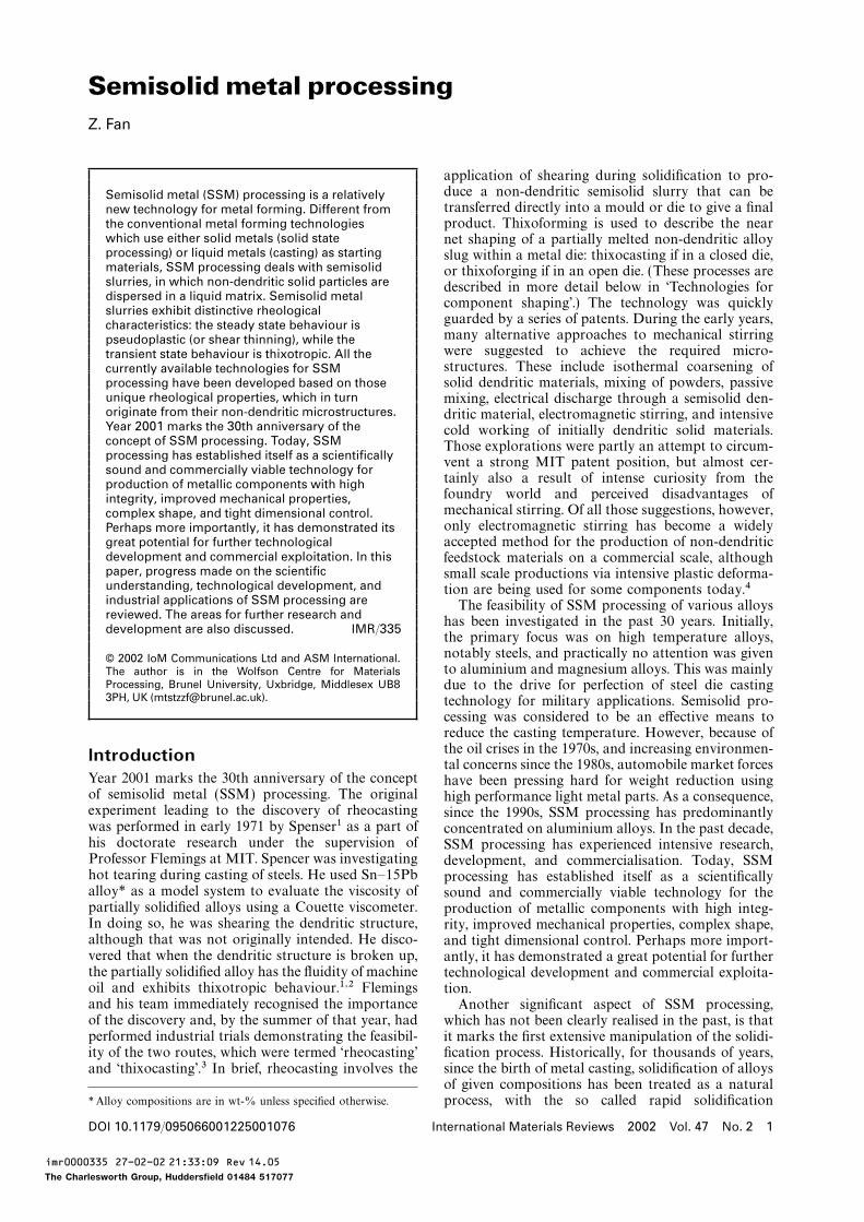
of the materials. Therefore, a true viscosity cannot becalculated. Another problem associated with this tech-nique is that it is almost impossible to study thix-otropy. Segregation may also occur due to thepressure gradient that develops as a result of the longlength required by this test and the increased per-meability at the walls. However, since similar flowconditions are present in an actual thixoformingprocess, the information extracted from such tests canbe relevant when comparable values of cross-sectionsare used.Recently, Koke and Modigell23,34 made a compari-
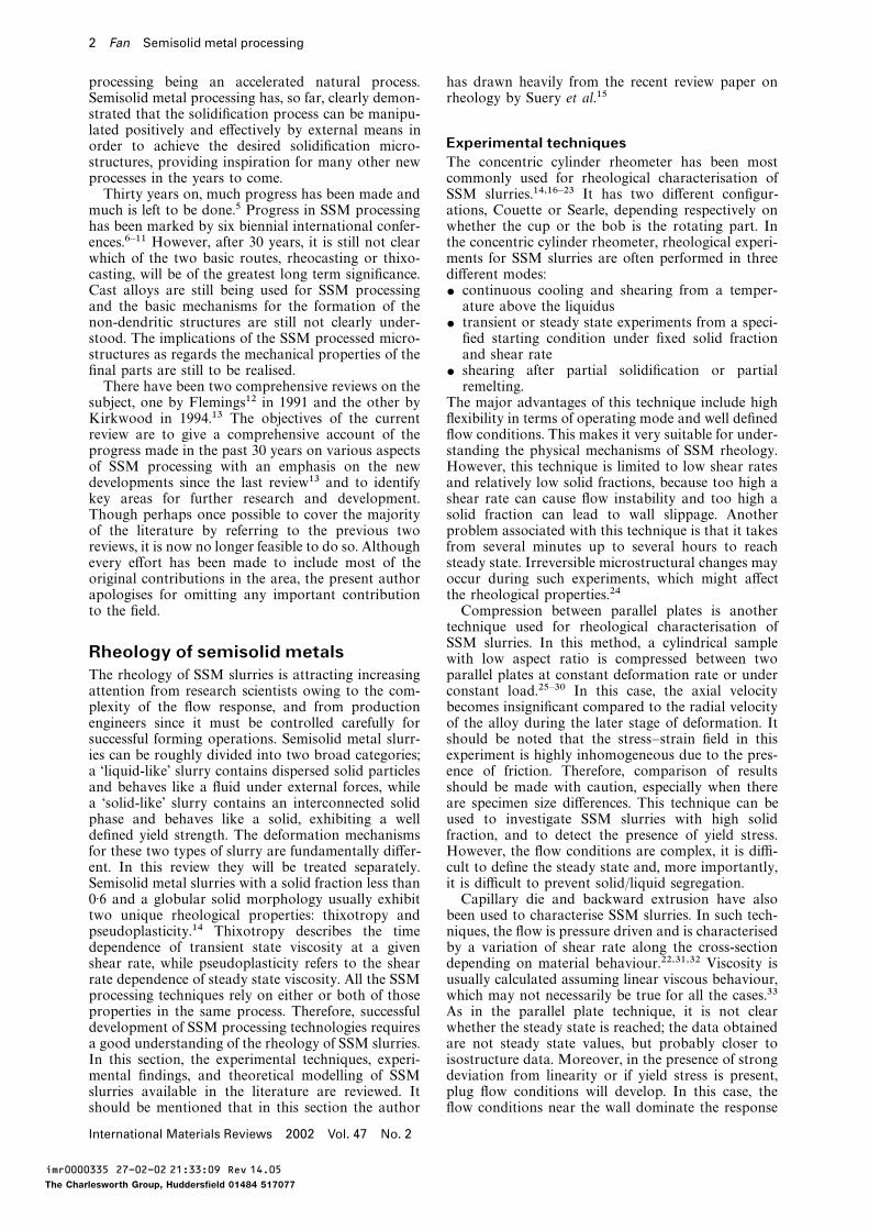
son of the steady state flow curves of semisolidSn–15Pb alloy obtained by different investi-gators,21,33,35 as shown in Fig. 1. There are substantialdiscrepancies in Fig. 1 for the same alloy compositionusing similar experimental techniques (concentric cyl-inder rheometer). Such variations in experimental 2 Steady state shear stress obtained from shearresults may be attributed to the following factors: rate transient experiments (from 25 to 400 s−1)
in 10 min intervals using smooth and grooved$ difference in geometry for cylinders (cylinders havecylinders (after Ref. 36)either a grooved (e.g. Ref. 23) or a smooth (e.g.
Ref. 35) surface; the former can promote a moreuniform particle distribution, whereas the lattermay lead to wall depletion or slippage (see experi- initiated numerous rheological studies on stirred SSM
slurries. Among them is the very extensive study bymental observations of Koke et al.36 in Fig. 2)resulting in a much reduced shear stress) Joly and Mehrabian14 on the Sn–Pb system. As
demonstrated by Joly and Mehrabian,14 the rheolog-$ difference in the methods used for calculating theshear rate ical phenomena in stirred SSM slurries can be
approximately divided into three categories:$ difference in the starting materials, which maybe partially solidified or partially remelted, and $ continuous cooling behaviour, which describes the
viscosity evolution during continuous cooling atconsequently have different particle size andmorphology.24 constant cooling rate and shear rate
$ pseudoplastic behaviour, which describes the shearIt appears from the above analysis that it is necessaryto standardise the testing methods and procedures. rate dependence of steady state viscosity, or shear
thinning behaviour$ thixotropic behaviour, which describes the timePhenomenologydependence of transient state viscosity.
The first investigation of the rheology of SSM slurriesThe continuous cooling behaviour gives the first
was conducted on the Sn–Pb system by Spencerinsight into the effects of solid fraction, shear rate,
et al.2 at MIT. They showed that the stirred SSMand cooling rate on the rheological behaviour of SSM
slurry at a solid fraction higher than 0·2 behaves likeslurries. In particular, it is more relevant to the
a non-Newtonian fluid with an apparent viscositypractical conditions set in SSM processing techniques
orders of magnitude less than that of a unstirredsuch as rheocasting and rheomoulding. Figure 3
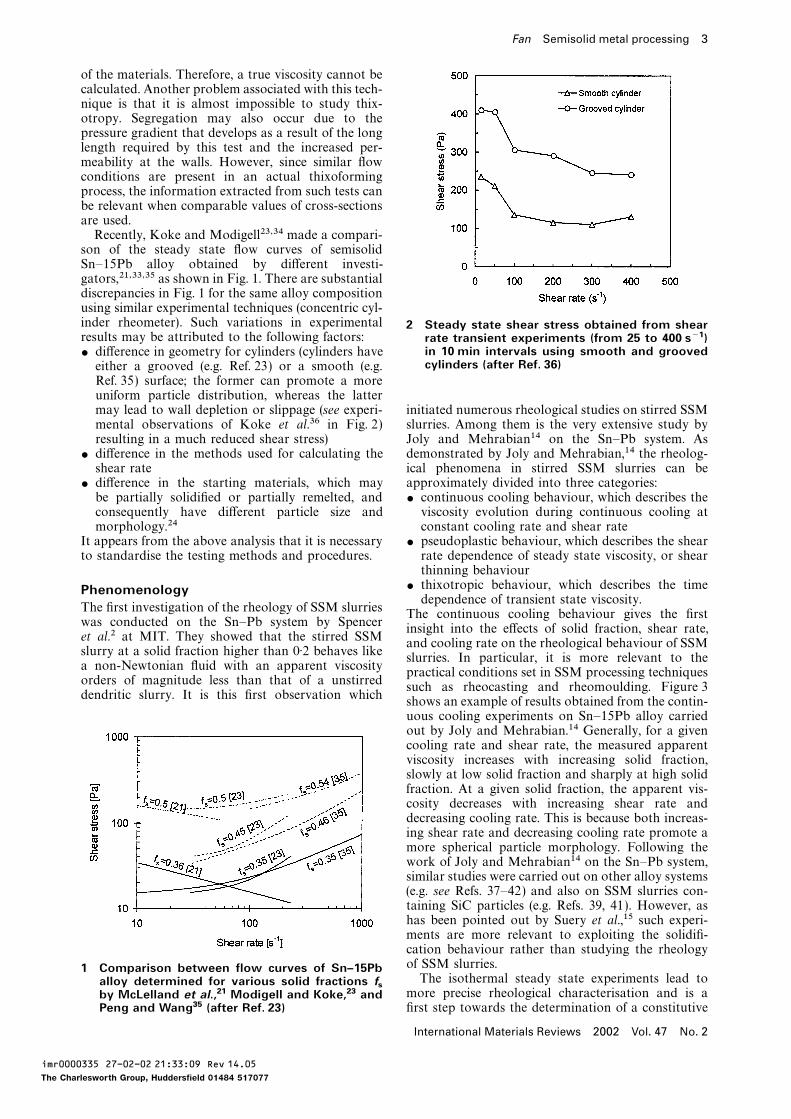
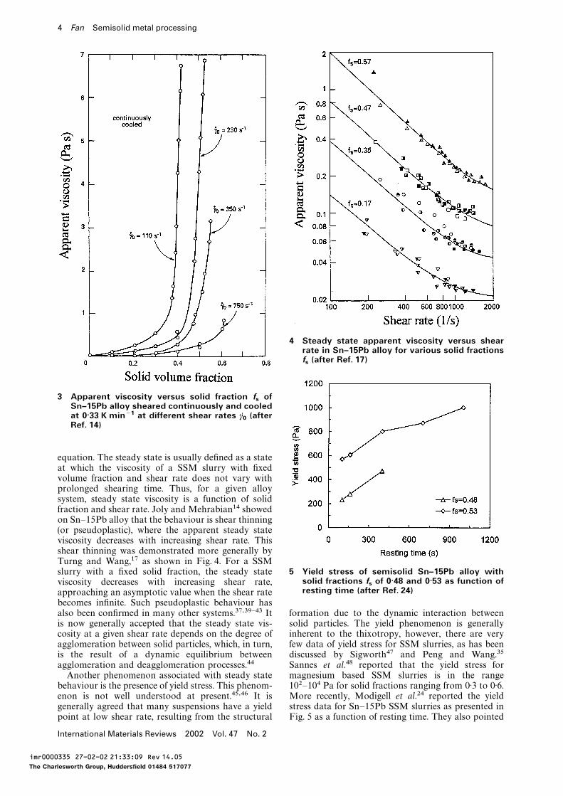
dendritic slurry. It is this first observation whichshows an example of results obtained from the contin-uous cooling experiments on Sn–15Pb alloy carriedout by Joly and Mehrabian.14 Generally, for a givencooling rate and shear rate, the measured apparentviscosity increases with increasing solid fraction,slowly at low solid fraction and sharply at high solidfraction. At a given solid fraction, the apparent vis-cosity decreases with increasing shear rate anddecreasing cooling rate. This is because both increas-ing shear rate and decreasing cooling rate promote amore spherical particle morphology. Following thework of Joly and Mehrabian14 on the Sn–Pb system,similar studies were carried out on other alloy systems(e.g. see Refs. 37–42) and also on SSM slurries con-taining SiC particles (e.g. Refs. 39, 41). However, ashas been pointed out by Suery et al.,15 such experi-ments are more relevant to exploiting the solidifi-cation behaviour rather than studying the rheologyof SSM slurries.1 Comparison between flow curves of Sn–15PbThe isothermal steady state experiments lead toalloy determined for various solid fractions f
s more precise rheological characterisation and is aby McLelland et al.,21 Modigell and Koke,23 andPeng and Wang35 (after Ref. 23) first step towards the determination of a constitutive
International Materials Reviews 2002 Vol. 47 No. 2
imr0000335 27-02-02 21:33:09 Rev 14.05
The Charlesworth Group, Huddersfield 01484 517077
4 Fan Semisolid metal processing
4 Steady state apparent viscosity versus shearrate in Sn–15Pb alloy for various solid fractionsfs(after Ref. 17)
3 Apparent viscosity versus solid fraction fsof
Sn–15Pb alloy sheared continuously and cooledat 0·33 K min−1 at different shear rates c
0(after
Ref. 14)
equation. The steady state is usually defined as a stateat which the viscosity of a SSM slurry with fixedvolume fraction and shear rate does not vary withprolonged shearing time. Thus, for a given alloysystem, steady state viscosity is a function of solidfraction and shear rate. Joly and Mehrabian14 showedon Sn–15Pb alloy that the behaviour is shear thinning(or pseudoplastic), where the apparent steady stateviscosity decreases with increasing shear rate. Thisshear thinning was demonstrated more generally byTurng and Wang,17 as shown in Fig. 4. For a SSM
5 Yield stress of semisolid Sn–15Pb alloy withslurry with a fixed solid fraction, the steady statesolid fractions f
sof 0·48 and 0·53 as function ofviscosity decreases with increasing shear rate,
resting time (after Ref. 24)approaching an asymptotic value when the shear ratebecomes infinite. Such pseudoplastic behaviour hasalso been confirmed in many other systems.37,39–43 It formation due to the dynamic interaction between
solid particles. The yield phenomenon is generallyis now generally accepted that the steady state vis-cosity at a given shear rate depends on the degree of inherent to the thixotropy, however, there are very
few data of yield stress for SSM slurries, as has beenagglomeration between solid particles, which, in turn,is the result of a dynamic equilibrium between discussed by Sigworth47 and Peng and Wang.35
Sannes et al.48 reported that the yield stress foragglomeration and deagglomeration processes.44Another phenomenon associated with steady state magnesium based SSM slurries is in the range
102–104 Pa for solid fractions ranging from 0·3 to 0·6.behaviour is the presence of yield stress. This phenom-enon is not well understood at present.45,46 It is More recently, Modigell et al.24 reported the yield
stress data for Sn–15Pb SSM slurries as presented ingenerally agreed that many suspensions have a yieldpoint at low shear rate, resulting from the structural Fig. 5 as a function of resting time. They also pointed
International Materials Reviews 2002 Vol. 47 No. 2
imr0000335 27-02-02 21:33:09 Rev 14.05
The Charlesworth Group, Huddersfield 01484 517077
Fan Semisolid metal processing 5
thickening behaviour was not detected for transitiontimes as low as 200 ms.
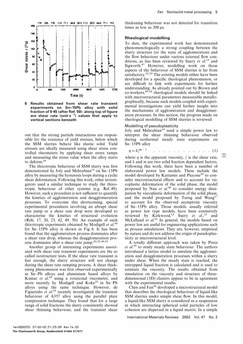
Rheological modellingTo date, the experimental work has demonstratedphenomenologically a strong coupling between theslurry structure (or the state of agglomeration) andthe flow behaviour under various external flow con-ditions, as has been reviewed by Suery et al.15 andSigworth.47 However, modelling work on thoseaspects of the behaviour of SSM slurries is far fromsatisfactory.52,53 The existing models either have beendeveloped for a specific rheological phenomenon, orare difficult to link with experiments for furtherunderstanding. As already pointed out by Brown andco-workers,49,54 rheological models should be linkedwith microstructural parameters measurable metallo-graphically, because such models coupled with experi-6 Results obtained from shear rate transientmental investigations can yield further insight intoexperiments on Sn–15Pb alloy with solidthe mechanisms of agglomeration and deagglomer-fraction of 0·45 (after Ref. 50): along top of figureation processes. In this section, the progress made onare shear rate (unit s−1) values that apply torheological modelling of SSM slurries is reviewed.vertical sections beneath
Modelling of pseudoplasticityJoly and Mehrabian14 used a simple power law tointerpret the shear thinning behaviour observedout that the strong particle interactions are respon-
sible for the existence of yield stresses, below which during isothermal steady state experiments onSn–15Pb alloythe SSM slurries behave like elastic solid. Yield
stresses are ideally measured using shear stress con-g=kcm−1 . . . . . . . . . . . . (1)
trolled rheometers by applying shear stress ramps1and measuring the stress value when the alloy starts where g is the apparent viscosity, c is the shear rate,
and k and m are two solid fraction dependent factors.to deform.24The thixotropic behaviour of SSM slurry was first Following this work, there have been a number of
elaborated power law models. These include thedemonstrated by Joly and Mehrabian14 on Sn–15Pballoy by measuring the hysteresis loops during a cyclic model developed by Kattamis and Piccone39 to con-
sider microstructural effects and to account for vis-shear deformation. Following this work, other investi-gators used a similar technique to study the thixo- coplastic deformation of the solid phase, the model
proposed by Nan et al.38 to consider energy dissi-tropic behaviour of other systems (e.g. Ref. 49).However, such a procedure is not sufficient to quantify pation by viscoplastic deformation of the solid phase,
and the model proposed by Turng and Wang17the kinetics of agglomeration and deagglomerationprocesses. To overcome this shortcoming, special to account for the observed asymptotic viscosity
of Sn–15Pb alloy. Those models, usually referredexperimental procedures involving an abrupt shearrate jump or a shear rate drop were developed to as power law type models, have been extensively
reviewed by Kirkwood,13 Suery et al.,15 andcharacterise the kinetics of structural evolution(Refs. 17, 20, 23, 42, 49, 50). An example of such McLelland et al.21 In general, the models based on
power law are useful for engineering applications suchthixotropic experiments obtained by Modigell et al.50for Sn–15Pb alloy is shown in Fig. 6. It has been as process simulations. They are, however, empirical
by nature and do not address the origin of pseudoplas-found that the agglomeration process dominates aftera shear rate drop, whereas the deagglomeration pro- ticity at microstructural level.
A totally different approach was taken by Perezcess dominates after a shear rate jump.20,23,49,51Another group of interesting experiments associ- et al.55 to study steady state behaviour. The authors
introduced a lattice model to simulate the agglomer-ated with shear rate transient experiments are the socalled isostructure tests. If the shear rate transient is ation and deagglomeration processes within a slurry
under shear. When the steady state is reached, thefast enough, the slurry structure will not changeduring the shear rate ramping process. A shear thick- entrapped liquid fraction is calculated and is used to
estimate the viscosity. The results obtained fromening phenomenon was first observed experimentallyin Sn–Pb alloys and aluminium based alloys by simulation on the viscosity and structure of three-
dimensional (3D) clusters appear to be in agreementKumar et al.18 using a rotational viscometer, andmore recently by Modigell and Koke23 in Sn–Pb with the experimental results.
Chen and Fan56 developed a microstructural modelalloys using the same technique. However, deFigueredo et al.30 recently investigated the transient that describes the rheological behaviour of liquid-like
SSM slurries under simple shear flow. In this model,behaviour of A357 alloy using the parallel platecompression technique. They found that for a large a liquid-like SSM slurry is considered as a suspension
in which interacting spherical solid particles of lowrange of solid fractions the slurry consistently showedshear thinning behaviour, and the transient shear cohesion are dispersed in a liquid matrix. In a simple
International Materials Reviews 2002 Vol. 47 No. 2
imr0000335 27-02-02 21:33:09 Rev 14.05
The Charlesworth Group, Huddersfield 01484 517077
6 Fan Semisolid metal processing
shear flow field, the dynamic interactions betweensolid particles result in the formation of agglomerates.Under the influence of viscous forces, collisionsbetween agglomerates lead to new agglomerates of alarger size and, at the same time, larger agglomeratesalso break up giving rise to agglomerates of a smallersize. At a particular time, the state of agglomerationis described by a structural parameter n, which isdefined as the average particle number in agglomer-ates. Based on such considerations, the time evolutionof the structural parameter n(t) has been derivedanalytically as a function of both microstructuralparameters and external flow conditions
1
n(t)=1
ne+A 1n0− 1neB exp{−lt} . . . . (2)
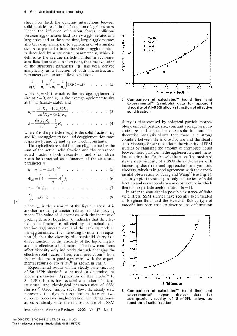
where n0=n(0), which is the average agglomeratesize at t=0, and ne is the average agglomerate size 7 Comparison of calculated57 (solid line) andat t=2 (steady state), and experimental40 (symbols) data for apparent
viscosity of Al–6·5Si alloy as function of effectivesolid fractionn
e=pd3K
d+12a1 f 2sKa
pd3Kd−6a2f
sKa. . . . . . . . (3)
slurry is characterised by spherical particle morph-l=6a1 f 2sKapd3
+1
2Kd. . . . . . . . . (4)
ology, uniform particle size, constant average agglom-erate size, and constant effective solid fraction. Thewhere d is the particle size, fs is the solid fraction, Ka theoretical analysis shows that there is a strongand Kd are agglomeration and deagglomeration rates coupling between the microstructure and the steadyrespectively, and a1 and a2 are model constants. state viscosity. Shear rate affects the viscosity of SSMThrough effective solid fraction (Weff , defined as the slurries by changing the amount of entrapped liquidsum of the actual solid fraction and the entrappedbetween solid particles in the agglomerates, and there-liquid fraction) both viscosity g and shear stressfore altering the effective solid fraction. The predictedt can be expressed as a function of the structuralsteady state viscosity of a SSM slurry decreases withparameter nincreasing shear rate and approaches an asymptotic
g=g0 (1−Weff )−5/2 . . . . . . . . . (5) viscosity, which is in good agreement with the experi-mental observation of Turng and Wang17 (see Fig. 8).
Weff=A1+ n−1n AB fs . . . . . . . . (6) The asymptotic viscosity is only a function of solidfraction and corresponds to a microstructure in whichthere is no particle agglomeration (n=1).t=g(n, c)c . . . . . . . . . . . . (7)In order to consider the possible existence of finiteyield stress, SSM slurries have recently been treated
dn
dt=g(n, c) . . . . . . . . . . . . (8)
as Bingham fluids and the Herschel–Bukley type of2model58 has been used to describe the deformationwhere g0 is the viscosity of the liquid matrix, A is
another model parameter related to the packingmode. The value of A decreases with the increase ofpacking density. Equation (6) indicates that the effec-tive solid fraction is affected by the actual solidfraction, agglomerate size, and the packing mode inthe agglomerates. It is interesting to note from equa-tion (5) that the viscosity of a semisolid slurry is adirect function of the viscosity of the liquid matrixand the effective solid fraction. The flow conditionsaffect viscosity only indirectly through changing theeffective solid fraction. Theoretical predictions57 fromthis model are in good agreement with the experi-mental results of Ito et al.,40 as shown in Fig. 7.Experimental results on the steady state viscosityof Sn–15Pb slurries17 were used to determine themodel parameters. Application of this model56 toSn–15Pb slurries has revealed a number of micro-structural and rheological characteristics of SSMslurries.57 Under simple shear flow, the steady state 8 Comparison of calculated57 (solid line) andrepresents the dynamic equilibrium between two experimental17 (open circles) data foropposite processes, agglomeration and deagglomer- asymptotic viscosity of Sn–15Pb alloys as
function of solid fractionation. At steady state, the microstructure of a SSM
International Materials Reviews 2002 Vol. 47 No. 2
imr0000335 27-02-02 21:33:09 Rev 14.05
The Charlesworth Group, Huddersfield 01484 517077
Fan Semisolid metal processing 7
characteristics of SSM slurries (e.g. Refs. 23, 35). The a double exponential expressionsteady state flow curve is given by the following
t(t)=te− (t0−te )equation
×Ca exp G− tl1H+ (1−a) exp G− tl2HDt=ta+k1 cn . . . . . . . . . . . (9)
. . . . . . . . . . . . . . . . . (12)where ta is the apparent yield stress and k1 and nare model parameters. Equation (9) is normally used
where l1 and l2 are fitted characteristic times thatto fit the experimental flow curve to determine thedepend on the initial and final shear rate and solid
yield stress data and the model parameters. However,fractions.
substantial differences exist between results fromBrown and co-workers have also used the general
different investigators. For example, the shear rateframework of internal variable models to propose,
exponent n for a SSM Sn–15Pb slurry with a solidbased on micromechanical considerations, a flow
fraction of 0·45 was found to be 0·83 by Peng andequation18,54
Wang,35 1·29 by Modigell and Koke,23 and−0·31 byMcLelland et al.21 It appears that the importance of
t=A(s)(c/c*)1/31− (c/c*)1/3
gL c+ (n+1)C(T )sfsgn+1L cnthe existence of yield stress in SSM slurries is beingrealised and that modelling work should include the . . . . . . . . (13)effect of finite yield stress, especially for SSM slurries
and an evolution equation49 for the structuralwith high solid fractions and under low shear rates.parametersIt should be noted, however, that Barnes59 has com-
mented that the existence of a yielding point maydepend on the experimental technique employed and
ds
st=H(T , f
s) (1−s)−R(T , f
s)scn . . . . (14)
may not therefore be a fundamental property ofthe system. where c= fs (1+0·1s) takes into account the
entrapped liquid due to agglomeration, c*=Modelling of thixotropy0·625–0.1s is a critical solid fraction,A(s) is a hydrody-
Modelling of thixotropic behaviour has been per-namic factor, gL is the viscosity of the liquid phase informed using predominantly the internal variablethe SSM slurry, C(T ) is a temperature dependent
framework20,23,50,51,54 or based on the Crossfactor with an Arrhenius form, H(T, fs ) is the agglom-model.60–62 A structural parameter s is normally usederation function that represents agglomeration of
as a scalar measure of the degree of agglomeration insolid particles, R(T, fs ) is the deagglomeration func-a SSM slurry. The parameter s varies between 1 andtion representing shear induced rupture of
0, corresponding to a fully agglomerated state and aparticle–particle bonds, and n=4. The steady state
fully deagglomerated state, respectively. The objectiveflow equation is given by setting ds/dt=0 such that
of such thixotropic modelling is to derive the timeevolution of the structural parameter s. This is done
s=sst=1
1+ (R/H)cn. . . . . . . . . (15)by using constitutional equations similar to equations
(7) and (8).The model was identified and validated on Sn–15PbMada and Ajersch20,51 used this general frameworkand Al–7Si–0·6Mg alloys, and used by Zavaliangosto model the thixotropic behaviour of A356 alloysand Lawley63 for simulation of the thixoforging pro-and the effect of SiC particles on it. The authorscess. It was further used qualitatively for high solidderived the following equation to describe thefraction ( fs>0·60) semisolid Sn–Pb alloys stirred inrelationship between the shear stress t(t) at time ta Couette rheometer.64and the shear rate after the jump where deagglomer-Further modelling work on thixotropy using theation processes are dominant20structural parameter s, but considering the presenceof finite yield stress, includes the work by Koke and
t(t)=ta+ (t0−t0 ) exp G− c
fa1+b1 cf
tH (10) co-workers34,65 and Burgos and Alexandrou.66However, the structure parameter s is not a welldefined parameter, and it is difficult to link with otherwhere t0 and te are the isostructural shear stress and microstructural parameters measurable usingthe steady state shear stress respectively, and al and metallographic techniques, and therefore difficult asbl are constants. In the case of reagglomeration during regards direct insight into the kinetics of structuralresting, the evolution of the shear stress with time atevolution during shearing.rest t
rafter resuming shear is given by20
The microstructural model developed by Chen andFan56 has also been applied to study the transient
t(tr)=t2− (t2−te ) exp G− c0
a2+b2 c0tH (11)
state behaviour of SSM slurries under variousdeformation conditions, such as isothermal shearing(Fig. 9), isothermal resting, isostructural shearing,where a is a model constant,t
2and t
eare the shear
stresses for a fully agglomerated state and the shear shear rate transient, and cyclic shearing (Fig. 10).67Theoretical predictions of the hysteresis loops understress when the shear rate is dropped respectively,
and a2 and b2 are constants. various cyclic deformation conditions have revealedthat the physical origin of thixotropy lies in the factQuaak et al.44 further elaborated equation (10) by
proposing, in the case of evolution of the shear stress that the deagglomeration kinetics is much faster thanthe agglomeration kinetics, with the former being aafter a shear rate jump in A356 and A356/SiC alloys,
International Materials Reviews 2002 Vol. 47 No. 2
imr0000335 27-02-02 21:33:09 Rev 14.05
The Charlesworth Group, Huddersfield 01484 517077
8 Fan Semisolid metal processing
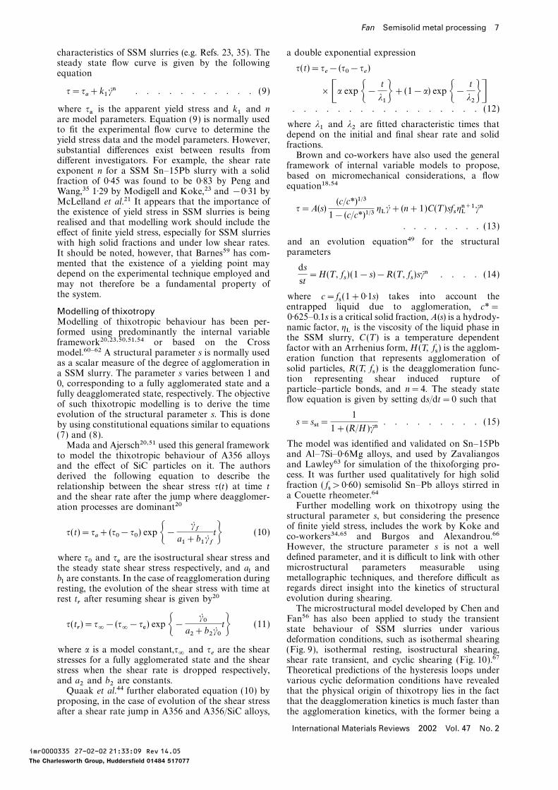
9 Comparison of calculated transient stateviscosity of Sn–15Pb alloy with solid fraction of
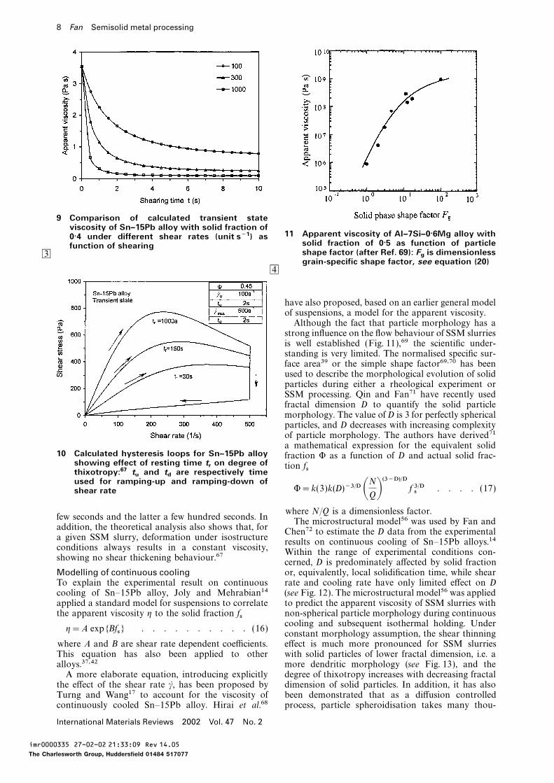
11 Apparent viscosity of Al–7Si–0·6Mg alloy with0·4 under different shear rates (unit s−1) assolid fraction of 0·5 as function of particlefunction of shearing
3 shape factor (after Ref. 69): Fgis dimensionless
grain-specific shape factor, see equation (20)4
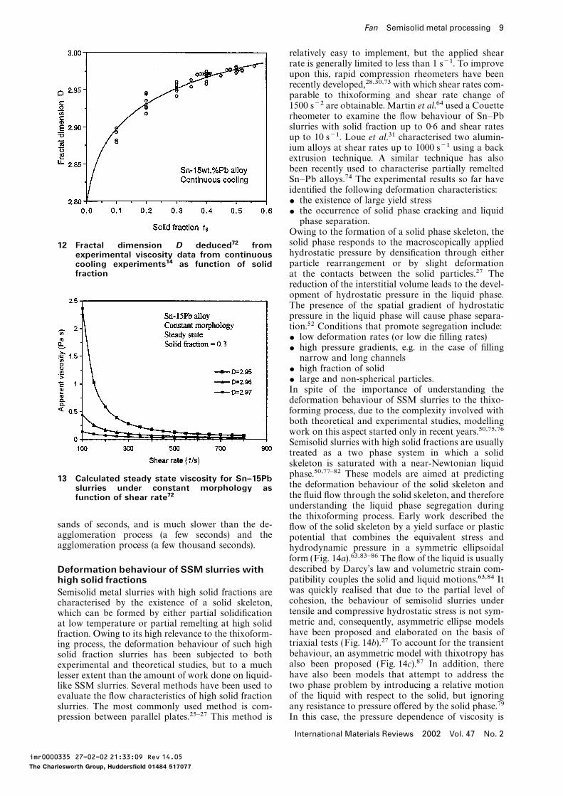
have also proposed, based on an earlier general modelof suspensions, a model for the apparent viscosity.Although the fact that particle morphology has astrong influence on the flow behaviour of SSM slurriesis well established (Fig. 11),69 the scientific under-standing is very limited. The normalised specific sur-face area39 or the simple shape factor69,70 has beenused to describe the morphological evolution of solidparticles during either a rheological experiment orSSM processing. Qin and Fan71 have recently usedfractal dimension D to quantify the solid particlemorphology. The value of D is 3 for perfectly sphericalparticles, and D decreases with increasing complexityof particle morphology. The authors have derived71a mathematical expression for the equivalent solid
10 Calculated hysteresis loops for Sn–15Pb alloy fraction W as a function of D and actual solid frac-showing effect of resting time t
ron degree of tion fsthixotropy:67 t
uand t
dare respectively time
used for ramping-up and ramping-down ofW=k(3)k(D)−3/D ANQB(3−D)/D f 3/Ds . . . . (17)shear rate
where N/Q is a dimensionless factor.few seconds and the latter a few hundred seconds. In
The microstructural model56 was used by Fan andaddition, the theoretical analysis also shows that, for
Chen72 to estimate the D data from the experimentala given SSM slurry, deformation under isostructure
results on continuous cooling of Sn–15Pb alloys.14conditions always results in a constant viscosity,
Within the range of experimental conditions con-showing no shear thickening behaviour.67
cerned, D is predominately affected by solid fractionor, equivalently, local solidification time, while shearModelling of continuous cooling
To explain the experimental result on continuous rate and cooling rate have only limited effect on D(see Fig. 12). The microstructural model56 was appliedcooling of Sn–15Pb alloy, Joly and Mehrabian14
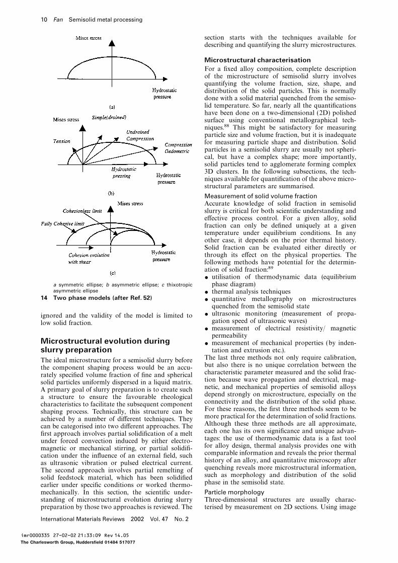
applied a standard model for suspensions to correlate to predict the apparent viscosity of SSM slurries withnon-spherical particle morphology during continuousthe apparent viscosity g to the solid fraction fscooling and subsequent isothermal holding. Under
g=A exp{Bfs} . . . . . . . . . . (16)constant morphology assumption, the shear thinningeffect is much more pronounced for SSM slurrieswhere A and B are shear rate dependent coefficients.
This equation has also been applied to other with solid particles of lower fractal dimension, i.e. amore dendritic morphology (see Fig. 13), and thealloys.37,42
A more elaborate equation, introducing explicitly degree of thixotropy increases with decreasing fractaldimension of solid particles. In addition, it has alsothe effect of the shear rate c, has been proposed by
Turng and Wang17 to account for the viscosity of been demonstrated that as a diffusion controlledprocess, particle spheroidisation takes many thou-continuously cooled Sn–15Pb alloy. Hirai et al.68
International Materials Reviews 2002 Vol. 47 No. 2
imr0000335 27-02-02 21:33:09 Rev 14.05
The Charlesworth Group, Huddersfield 01484 517077
Fan Semisolid metal processing 9
relatively easy to implement, but the applied shearrate is generally limited to less than 1 s−1. To improveupon this, rapid compression rheometers have beenrecently developed,28,30,73 with which shear rates com-parable to thixoforming and shear rate change of1500 s−2 are obtainable. Martin et al.64 used a Couetterheometer to examine the flow behaviour of Sn–Pbslurries with solid fraction up to 0·6 and shear ratesup to 10 s−1. Loue et al.31 characterised two alumin-ium alloys at shear rates up to 1000 s−1 using a backextrusion technique. A similar technique has alsobeen recently used to characterise partially remeltedSn–Pb alloys.74 The experimental results so far haveidentified the following deformation characteristics:$ the existence of large yield stress$ the occurrence of solid phase cracking and liquidphase separation.
Owing to the formation of a solid phase skeleton, thesolid phase responds to the macroscopically applied12 Fractal dimension D deduced72 fromhydrostatic pressure by densification through eitherexperimental viscosity data from continuousparticle rearrangement or by slight deformationcooling experiments14 as function of solid
fraction at the contacts between the solid particles.27 Thereduction of the interstitial volume leads to the devel-opment of hydrostatic pressure in the liquid phase.The presence of the spatial gradient of hydrostaticpressure in the liquid phase will cause phase separa-tion.52 Conditions that promote segregation include:$ low deformation rates (or low die filling rates)$ high pressure gradients, e.g. in the case of fillingnarrow and long channels
$ high fraction of solid$ large and non-spherical particles.In spite of the importance of understanding thedeformation behaviour of SSM slurries to the thixo-forming process, due to the complexity involved withboth theoretical and experimental studies, modellingwork on this aspect started only in recent years.50,75,76Semisolid slurries with high solid fractions are usuallytreated as a two phase system in which a solidskeleton is saturated with a near-Newtonian liquidphase.50,77–82 These models are aimed at predicting13 Calculated steady state viscosity for Sn–15Pbthe deformation behaviour of the solid skeleton andslurries under constant morphology asthe fluid flow through the solid skeleton, and thereforefunction of shear rate72understanding the liquid phase segregation duringthe thixoforming process. Early work described the
sands of seconds, and is much slower than the de- flow of the solid skeleton by a yield surface or plasticagglomeration process (a few seconds) and the potential that combines the equivalent stress andagglomeration process (a few thousand seconds). hydrodynamic pressure in a symmetric ellipsoidal
form (Fig. 14a).63,83–86 The flow of the liquid is usuallydescribed by Darcy’s law and volumetric strain com-Deformation behaviour of SSM slurries withpatibility couples the solid and liquid motions.63,84 Ithigh solid fractionswas quickly realised that due to the partial level ofSemisolid metal slurries with high solid fractions arecohesion, the behaviour of semisolid slurries undercharacterised by the existence of a solid skeleton,tensile and compressive hydrostatic stress is not sym-which can be formed by either partial solidificationmetric and, consequently, asymmetric ellipse modelsat low temperature or partial remelting at high solidhave been proposed and elaborated on the basis offraction. Owing to its high relevance to the thixoform-triaxial tests (Fig. 14b).27 To account for the transienting process, the deformation behaviour of such highbehaviour, an asymmetric model with thixotropy hassolid fraction slurries has been subjected to bothalso been proposed (Fig. 14c).87 In addition, thereexperimental and theoretical studies, but to a muchhave also been models that attempt to address thelesser extent than the amount of work done on liquid-two phase problem by introducing a relative motionlike SSM slurries. Several methods have been used toof the liquid with respect to the solid, but ignoringevaluate the flow characteristics of high solid fractionany resistance to pressure offered by the solid phase.79slurries. The most commonly used method is com-
pression between parallel plates.25–27 This method is In this case, the pressure dependence of viscosity is
International Materials Reviews 2002 Vol. 47 No. 2
imr0000335 27-02-02 21:33:09 Rev 14.05
The Charlesworth Group, Huddersfield 01484 517077
10 Fan Semisolid metal processing
section starts with the techniques available fordescribing and quantifying the slurry microstructures.
Microstructural characterisationFor a fixed alloy composition, complete descriptionof the microstructure of semisolid slurry involvesquantifying the volume fraction, size, shape, anddistribution of the solid particles. This is normallydone with a solid material quenched from the semiso-lid temperature. So far, nearly all the quantificationshave been done on a two-dimensional (2D) polishedsurface using conventional metallographical tech-niques.88 This might be satisfactory for measuringparticle size and volume fraction, but it is inadequatefor measuring particle shape and distribution. Solidparticles in a semisolid slurry are usually not spheri-cal, but have a complex shape; more importantly,solid particles tend to agglomerate forming complex3D clusters. In the following subsections, the tech-niques available for quantification of the above micro-structural parameters are summarised.
Measurement of solid volume fractionAccurate knowledge of solid fraction in semisolidslurry is critical for both scientific understanding andeffective process control. For a given alloy, solidfraction can only be defined uniquely at a giventemperature under equilibrium conditions. In anyother case, it depends on the prior thermal history.Solid fraction can be evaluated either directly orthrough its effect on the physical properties. Thefollowing methods have potential for the determin-ation of solid fraction:89$ utilisation of thermodynamic data (equilibriumphase diagram)a symmetric ellipse; b asymmetric ellipse; c thixotropic
asymmetric ellipse $ thermal analysis techniques14 Two phase models (after Ref. 52) $ quantitative metallography on microstructures
quenched from the semisolid state$ ultrasonic monitoring (measurement of propa-ignored and the validity of the model is limited togation speed of ultrasonic waves)low solid fraction.
$ measurement of electrical resistivity/ magneticpermeability
Microstructural evolution during $ measurement of mechanical properties (by inden-tation and extrusion etc.).slurry preparation
The last three methods not only require calibration,The ideal microstructure for a semisolid slurry beforebut also there is no unique correlation between thethe component shaping process would be an accu-characteristic parameter measured and the solid frac-rately specified volume fraction of fine and sphericaltion because wave propagation and electrical, mag-solid particles uniformly dispersed in a liquid matrix.netic, and mechanical properties of semisolid alloysA primary goal of slurry preparation is to create suchdepend strongly on microstructure, especially on thea structure to ensure the favourable rheologicalconnectivity and the distribution of the solid phase.characteristics to facilitate the subsequent componentFor these reasons, the first three methods seem to beshaping process. Technically, this structure can bemore practical for the determination of solid fractions.achieved by a number of different techniques. TheyAlthough these three methods are all approximate,can be categorised into two different approaches. Theeach one has its own significance and unique advan-first approach involves partial solidification of a melttages: the use of thermodynamic data is a fast toolunder forced convection induced by either electro-for alloy design, thermal analysis provides one withmagnetic or mechanical stirring, or partial solidifi-comparable information and reveals the prior thermalcation under the influence of an external field, suchhistory of an alloy, and quantitative microscopy afteras ultrasonic vibration or pulsed electrical current.quenching reveals more microstructural information,The second approach involves partial remelting ofsuch as morphology and distribution of the solidsolid feedstock material, which has been solidifiedphase in the semisolid state.earlier under specific conditions or worked thermo-
mechanically. In this section, the scientific under- Particle morphologyThree-dimensional structures are usually charac-standing of microstructural evolution during slurry
preparation by those two approaches is reviewed. The terised by measurement on 2D sections. Using image
International Materials Reviews 2002 Vol. 47 No. 2
imr0000335 27-02-02 21:33:09 Rev 14.05
The Charlesworth Group, Huddersfield 01484 517077
Fan Semisolid metal processing 11
analysing systems, one can measure number, interface To model the deformation behaviour of SSM slurr-ies, a structural parameter s has often been used tolength, and areas of objects.88 To quantify particle
morphology, an object-specific shape factor F is usu- describe the particle distribution.18,49,54 In a com-pletely agglomerated state s=1, while for a com-ally used. Two different expressions for the shape
factor F have been used in the literature pletely dispersed state s=0. Thus, 0∏s∏1. However,this parameter is not well defined and is extremelydifficult to measure experimentally.96F1=
4pA
P2. . . . . . . . . . . . (18)
Another way to describe the particle distributionin semisolid slurry is to use the stereological para-meter ‘contiguity volume’, which was originally devel-F2=
P24pA
. . . . . . . . . . . . (19)oped97,98 by Gurland and Lee and defined by thefollowing equation
where A and P represent the area and perimeter offsc=Cs fs . . . . . . . . . . . . (21)the object, respectively. In both cases, F=1 refers to
a perfectly spherical morphology, while for very com- where fsc is the contiguity volume and Cs is theplex shapes, F1�0 and F2�2. Equations (18) and contiguity of the solid phase. Uggowitzer and(19) are generally adequate for morphological quanti- co-workers99,100 recently applied the contiguityfication of compact and well dispersed particles. volume to characterise the particle distribution inHowever, for more open particles such as dendrites, SSM slurries. Their experimental results showed thata 2D cut of such a particle gives rise to several the contiguity volume should not exceed a value ofapparently isolated images, which are usually treated 0·3 for maximum thixotropic material flow; however,by an image analysing system as several individual on the other hand, a value below 0·1 is not suitableparticles. Thus, an average of object-specific shape for thixoforming because of the poor stability of thefactor may not reflect the true complexity of particles slug for handling. They also demonstrated that thewith an open structure. contiguity volume could be improved by addition ofLoue and Suery70 introduced a modified dimen- minor alloying elements.100sionless grain-specific shape factor Fg , as defined by More recently, Chen and Fan56 proposed using thethe following equation average number of particles in agglomerates as a
parameter to describe the degree of particle agglomer-ation in SSM slurry. Obviously, this parameter canFg=
1
6pfs
S2VNA
. . . . . . . . . . . (20)be determined experimentally using a standardmetallographical method. The concerned parameter
where SV is the solid/liquid interfacial area per unit has been successfully used for the development of avolume and NA is the number of grains per unit area. microstructural model for SSM slurries.56 The authorsThe authors have demonstrated that Fg describes have demonstrated that the viscosity of a specifiedmore accurately the particle morphology than does SSM slurry has a one-to-one correspondence to theF (equations (18) and (19)). However, the parameter average number of particles in agglomerates.NA in equation (20) measured by image analysis may Most of the experimental investigations of semisolidnot accurately reflect the true particle density. microstructure are based on 2D observations that do
In most cases of SSM processing, the geometry not allow straightforward conclusions about the exactof the solid phase is irregular rather than spherical. state of agglomeration. Attempts have been made toBy noting that the dendrite is a typical fractal struc- obtain 3D images by serial sectioning.40,101–104ture90 and that the irregular geometry of solidifying However, serial sectioning is very time consumingcrystals can be quantitatively characterised by the and, more importantly, this technique may not befractal theory,91 Qin and Fan71 proposed describing adequate to characterise the degree of agglomerationthe morphology of equiaxed dendrites using the frac- in slurries with fine particle size due to its lowtal dimension D. The fractal dimension of a solid resolution (about 20 mm). More recently, advancedparticle can be measured by many different methods, techniques, such as electron back scattered diffrac-such as slit island analysis,91 profile analysis,92 direct tion96,105 and X-ray microtomography,96 have beensurface area analysis,93 and variation-correlation used.analysis.94 It has been shown recently that for a welldeveloped dendrite under diffusion controlled con- Solidification behaviour under forceddition D=2·5 (Ref. 95), while for a perfectly spherical convectionparticle D=3. The concepts of fractal dimension D
Nearly all the alloys of commercial importance solid-and the equivalent solid fraction W have been success-ify dendritically, with either a columnar or an equi-fully applied to model the rheological behaviour ofaxed dendritic structure.12 During dendriticSSM slurries with non-spherical particles.72solidification of castings and ingots, a number ofprocesses take place simultaneously within the semi-Particle distribution
For a given slurry system with a fixed solid fraction, solid region. These include crystallisation, soluteredistribution, ripening, interdendritic fluid flow, andparticle distribution in the liquid matrix has a pro-
nounced influence on the slurry rheology and has a solid movement. The dendritic structure is greatlyaffected by the interdendritic flow and solid move-strong implication regarding the quality of the SSM
processed components. Despite such importance, cur- ment, which, in conventional solidification, is causedby internal factors such as density difference andrently there is no mature method for the quantifi-
cation of particle distribution in the liquid matrix. heterogeneous distribution of temperature. The effects
International Materials Reviews 2002 Vol. 47 No. 2
imr0000335 27-02-02 21:33:09 Rev 14.05
The Charlesworth Group, Huddersfield 01484 517077
12 Fan Semisolid metal processing
of those processes on the solidified microstructureshave been reviewed previously by Flemings,106 andmore recently by Boettinger et al.107 In this review,discussion is confined to forced convection with amuch larger intensity.
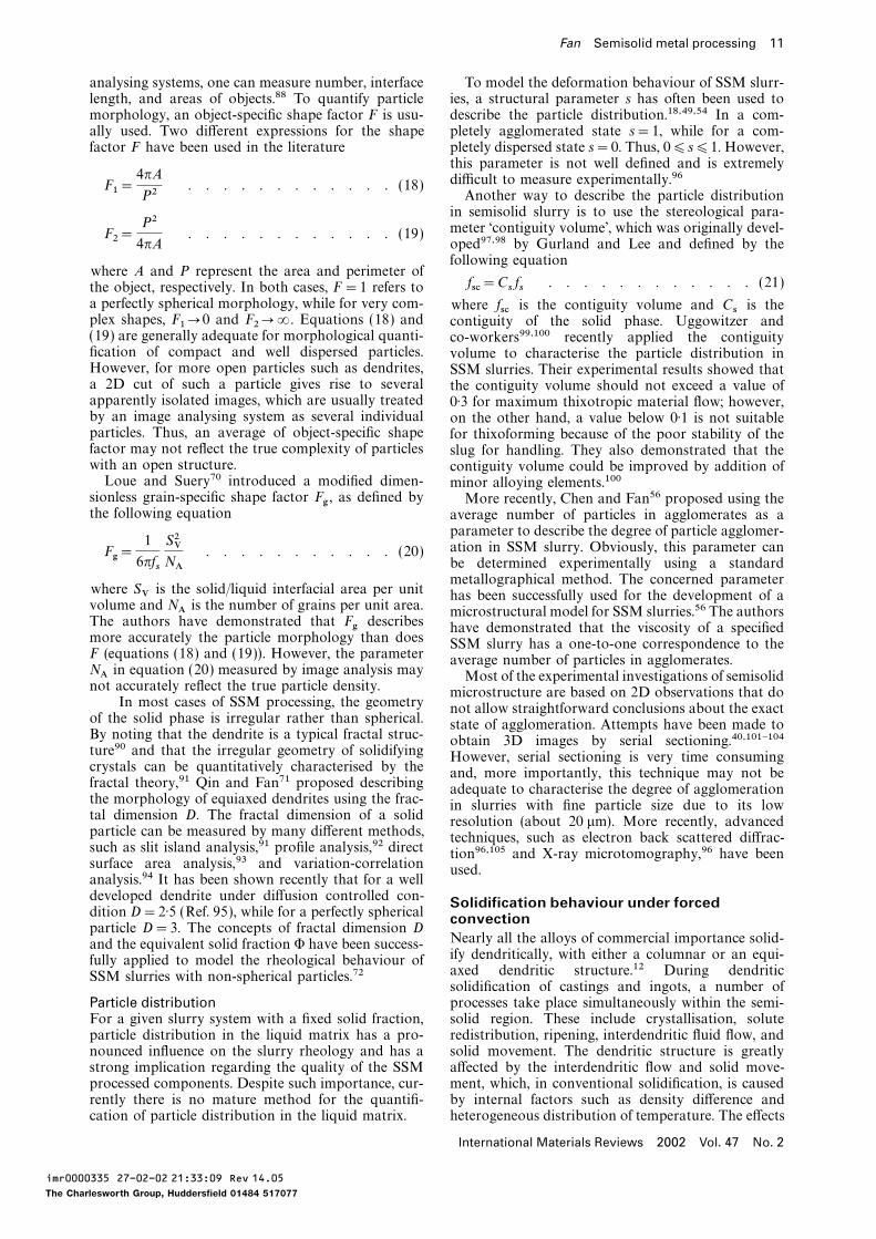
PhenomenologyIn studying conventional solidification, transparentorganic alloys have been intensively used to investi-gate the solidification behaviour at microstructurallevel by direct observation. However, this may not bepossible for solidification under forced convection,even using organic analogue, due to the blurred imagecaused by intensive stirring.108 For this reason, currentunderstanding of the solidification behaviour underforced convention is obtained indirectly by examin-ation of the final solidified microstructures.It has been conclusively established from experi- 15 Quenched microstructure of Sn–15Pb alloy at
early stage of solidification in twin screwmental observations that solidification under meltrheomoulding (TSRM) machine115stirring produces non-dendritic structures, as has been
summarised in previous reviews.12,13 The early workby Spencer et al.2 and Joly and Mehrabian14 on theSn–Pb system using rotational rheometers confirmedthat the solid phase in the semisolid state has eithera degenerated dendritic structure or rosette morph-ology. With prolonged stirring time, such particleschange to a more or less spherical morphology con-taining entrapped liquid by a ripening process.Increasing the shear rate accelerates this morphologi-cal transition and reduces the amount of entrappedliquid inside the solid particles.14 The rosette morph-ology of solid particles has also been observed inmany stirred alloys by other investigators109–112 usingrod and impeller types of stirrer. Later work onsolidification under magnetohydrodynamic (MHD)stirring confirmed the formation of a fine and degener-ated dendritic structure (see summary in Refs. 12, 13).
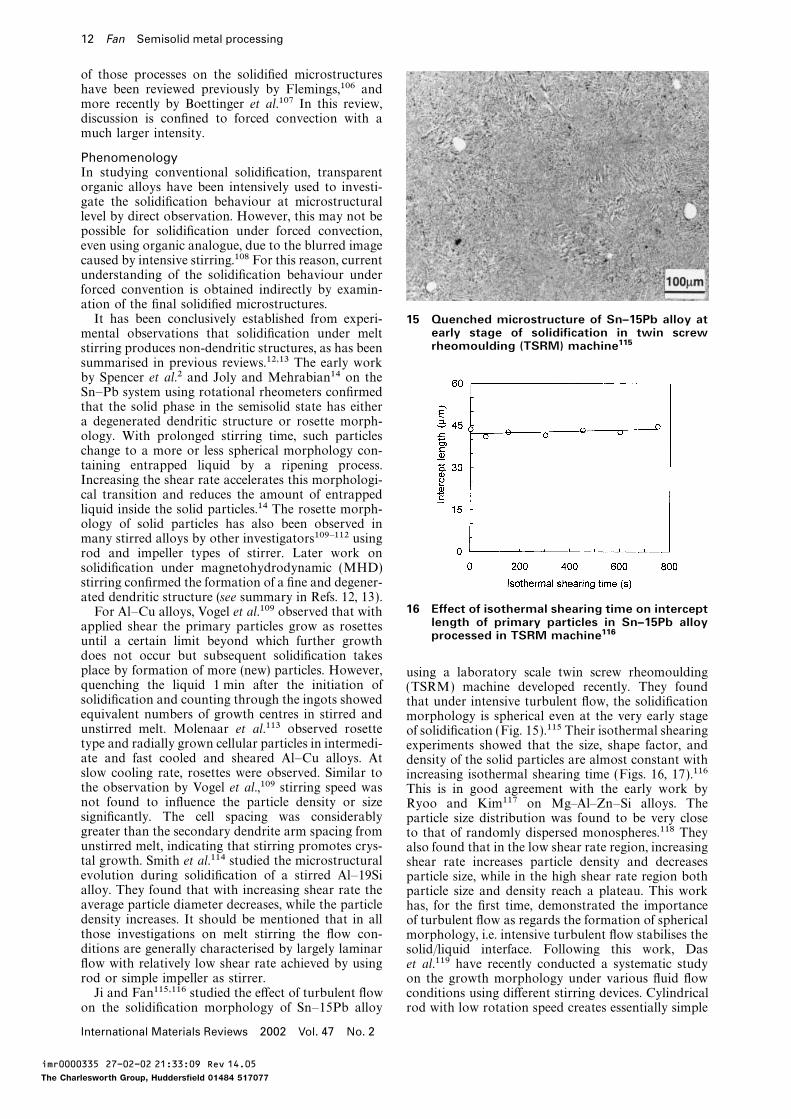
16 Effect of isothermal shearing time on interceptFor Al–Cu alloys, Vogel et al.109 observed that withlength of primary particles in Sn–15Pb alloyapplied shear the primary particles grow as rosettesprocessed in TSRM machine116until a certain limit beyond which further growth
does not occur but subsequent solidification takesplace by formation of more (new) particles. However, using a laboratory scale twin screw rheomouldingquenching the liquid 1 min after the initiation of (TSRM) machine developed recently. They foundsolidification and counting through the ingots showed that under intensive turbulent flow, the solidificationequivalent numbers of growth centres in stirred and morphology is spherical even at the very early stageunstirred melt. Molenaar et al.113 observed rosette of solidification (Fig. 15).115 Their isothermal shearingtype and radially grown cellular particles in intermedi- experiments showed that the size, shape factor, andate and fast cooled and sheared Al–Cu alloys. At density of the solid particles are almost constant withslow cooling rate, rosettes were observed. Similar to increasing isothermal shearing time (Figs. 16, 17).116the observation by Vogel et al.,109 stirring speed was This is in good agreement with the early work bynot found to influence the particle density or size Ryoo and Kim117 on Mg–Al–Zn–Si alloys. Thesignificantly. The cell spacing was considerably particle size distribution was found to be very closegreater than the secondary dendrite arm spacing from to that of randomly dispersed monospheres.118 Theyunstirred melt, indicating that stirring promotes crys- also found that in the low shear rate region, increasingtal growth. Smith et al.114 studied the microstructural shear rate increases particle density and decreasesevolution during solidification of a stirred Al–19Si particle size, while in the high shear rate region bothalloy. They found that with increasing shear rate the particle size and density reach a plateau. This workaverage particle diameter decreases, while the particle has, for the first time, demonstrated the importancedensity increases. It should be mentioned that in all of turbulent flow as regards the formation of sphericalthose investigations on melt stirring the flow con- morphology, i.e. intensive turbulent flow stabilises theditions are generally characterised by largely laminar solid/liquid interface. Following this work, Dasflow with relatively low shear rate achieved by using et al.119 have recently conducted a systematic studyrod or simple impeller as stirrer. on the growth morphology under various fluid flowJi and Fan115,116 studied the effect of turbulent flow conditions using different stirring devices. Cylindrical
rod with low rotation speed creates essentially simpleon the solidification morphology of Sn–15Pb alloy
International Materials Reviews 2002 Vol. 47 No. 2
imr0000335 27-02-02 21:33:09 Rev 14.05
The Charlesworth Group, Huddersfield 01484 517077
Fan Semisolid metal processing 13
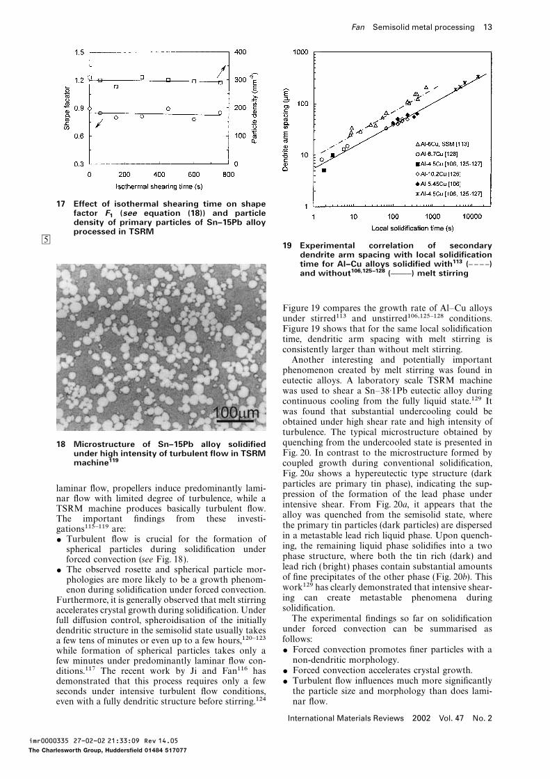
17 Effect of isothermal shearing time on shapefactor F
1(see equation (18)) and particle
density of primary particles of Sn–15Pb alloyprocessed in TSRM
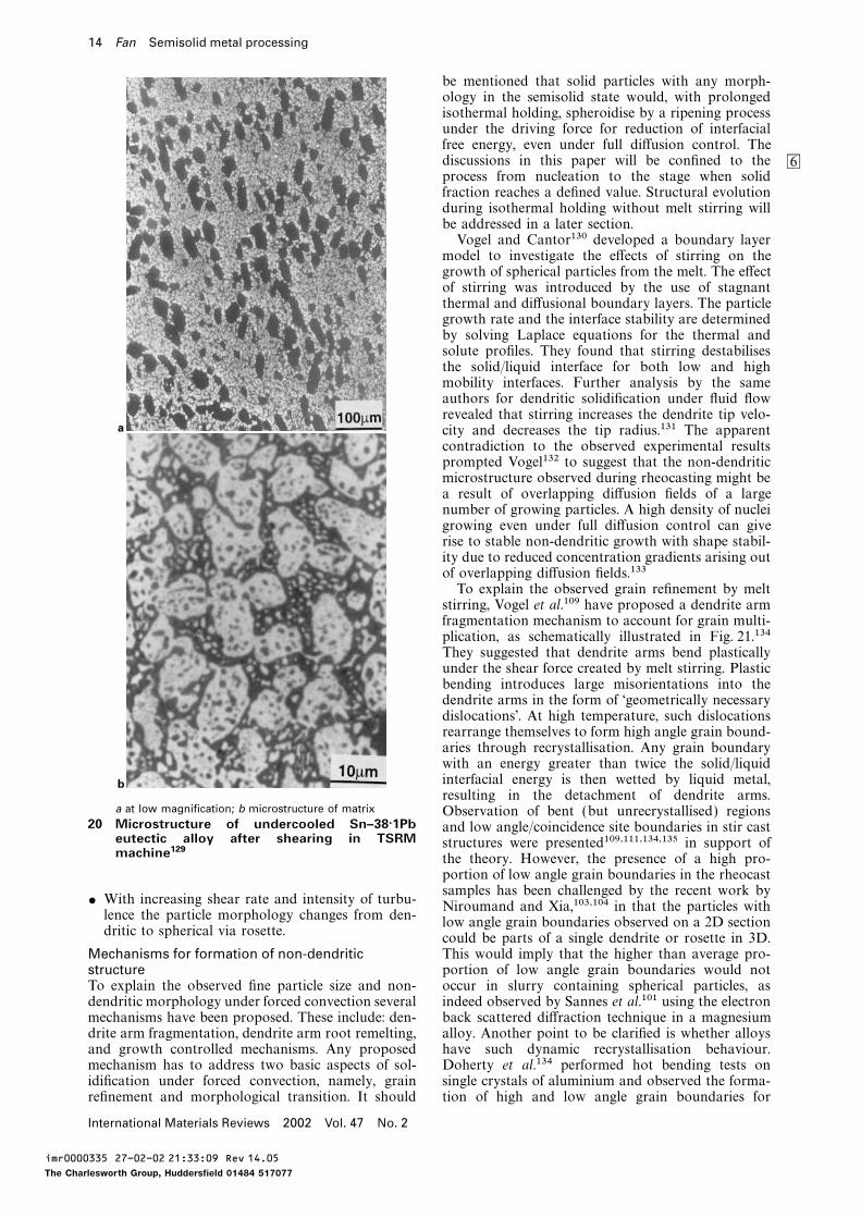
519 Experimental correlation of secondary
dendrite arm spacing with local solidificationtime for Al–Cu alloys solidified with113 (D D D D)and without106,125–128 (CCD) melt stirring
Figure 19 compares the growth rate of Al–Cu alloysunder stirred113 and unstirred106,125–128 conditions.Figure 19 shows that for the same local solidificationtime, dendritic arm spacing with melt stirring isconsistently larger than without melt stirring.Another interesting and potentially importantphenomenon created by melt stirring was found ineutectic alloys. A laboratory scale TSRM machinewas used to shear a Sn–38·1Pb eutectic alloy duringcontinuous cooling from the fully liquid state.129 Itwas found that substantial undercooling could beobtained under high shear rate and high intensity ofturbulence. The typical microstructure obtained byquenching from the undercooled state is presented in18 Microstructure of Sn–15Pb alloy solidifiedFig. 20. In contrast to the microstructure formed byunder high intensity of turbulent flow in TSRM
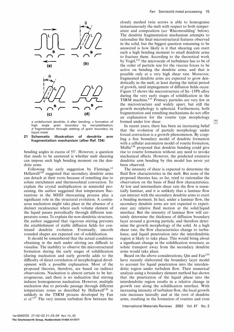
machine119 coupled growth during conventional solidification,Fig. 20a shows a hypereutectic type structure (darkparticles are primary tin phase), indicating the sup-laminar flow, propellers induce predominantly lami-pression of the formation of the lead phase undernar flow with limited degree of turbulence, while aintensive shear. From Fig. 20a, it appears that theTSRM machine produces basically turbulent flow.alloy was quenched from the semisolid state, whereThe important findings from these investi-the primary tin particles (dark particles) are dispersedgations115–119 are:in a metastable lead rich liquid phase. Upon quench-
$ Turbulent flow is crucial for the formation ofing, the remaining liquid phase solidifies into a twospherical particles during solidification underphase structure, where both the tin rich (dark) andforced convection (see Fig. 18).lead rich (bright) phases contain substantial amounts
$ The observed rosette and spherical particle mor-of fine precipitates of the other phase (Fig. 20b). Thisphologies are more likely to be a growth phenom-work129 has clearly demonstrated that intensive shear-enon during solidification under forced convection.ing can create metastable phenomena duringFurthermore, it is generally observed that melt stirringsolidification.accelerates crystal growth during solidification. UnderThe experimental findings so far on solidificationfull diffusion control, spheroidisation of the initiallyunder forced convection can be summarised asdendritic structure in the semisolid state usually takesfollows:a few tens of minutes or even up to a few hours,120–123$ Forced convection promotes finer particles with awhile formation of spherical particles takes only anon-dendritic morphology.few minutes under predominantly laminar flow con-
$ Forced convection accelerates crystal growth.ditions.117 The recent work by Ji and Fan116 has$ Turbulent flow influences much more significantlydemonstrated that this process requires only a fewthe particle size and morphology than does lami-seconds under intensive turbulent flow conditions,
even with a fully dendritic structure before stirring.124 nar flow.
International Materials Reviews 2002 Vol. 47 No. 2
imr0000335 27-02-02 21:33:09 Rev 14.05
The Charlesworth Group, Huddersfield 01484 517077
14 Fan Semisolid metal processing
be mentioned that solid particles with any morph-ology in the semisolid state would, with prolongedisothermal holding, spheroidise by a ripening processunder the driving force for reduction of interfacialfree energy, even under full diffusion control. Thediscussions in this paper will be confined to the 6process from nucleation to the stage when solidfraction reaches a defined value. Structural evolutionduring isothermal holding without melt stirring willbe addressed in a later section.Vogel and Cantor130 developed a boundary layermodel to investigate the effects of stirring on thegrowth of spherical particles from the melt. The effectof stirring was introduced by the use of stagnantthermal and diffusional boundary layers. The particlegrowth rate and the interface stability are determinedby solving Laplace equations for the thermal andsolute profiles. They found that stirring destabilisesthe solid/liquid interface for both low and highmobility interfaces. Further analysis by the sameauthors for dendritic solidification under fluid flowrevealed that stirring increases the dendrite tip velo-city and decreases the tip radius.131 The apparentcontradiction to the observed experimental resultsprompted Vogel132 to suggest that the non-dendriticmicrostructure observed during rheocasting might bea result of overlapping diffusion fields of a largenumber of growing particles. A high density of nucleigrowing even under full diffusion control can giverise to stable non-dendritic growth with shape stabil-ity due to reduced concentration gradients arising outof overlapping diffusion fields.133To explain the observed grain refinement by meltstirring, Vogel et al.109 have proposed a dendrite armfragmentation mechanism to account for grain multi-plication, as schematically illustrated in Fig. 21.134They suggested that dendrite arms bend plasticallyunder the shear force created by melt stirring. Plasticbending introduces large misorientations into thedendrite arms in the form of ‘geometrically necessarydislocations’. At high temperature, such dislocationsrearrange themselves to form high angle grain bound-aries through recrystallisation. Any grain boundarywith an energy greater than twice the solid/liquidinterfacial energy is then wetted by liquid metal,
a
bresulting in the detachment of dendrite arms.
a at low magnification; b microstructure of matrix Observation of bent (but unrecrystallised) regions20 Microstructure of undercooled Sn–38·1Pb and low angle/coincidence site boundaries in stir cast
eutectic alloy after shearing in TSRM structures were presented109,111,134,135 in support ofmachine129 the theory. However, the presence of a high pro-
portion of low angle grain boundaries in the rheocastsamples has been challenged by the recent work by
$ With increasing shear rate and intensity of turbu-Niroumand and Xia,103,104 in that the particles with
lence the particle morphology changes from den-low angle grain boundaries observed on a 2D section
dritic to spherical via rosette.could be parts of a single dendrite or rosette in 3D.This would imply that the higher than average pro-Mechanisms for formation of non-dendritic
structure portion of low angle grain boundaries would notoccur in slurry containing spherical particles, asTo explain the observed fine particle size and non-
dendritic morphology under forced convection several indeed observed by Sannes et al.101 using the electronback scattered diffraction technique in a magnesiummechanisms have been proposed. These include: den-
drite arm fragmentation, dendrite arm root remelting, alloy. Another point to be clarified is whether alloyshave such dynamic recrystallisation behaviour.and growth controlled mechanisms. Any proposed
mechanism has to address two basic aspects of sol- Doherty et al.134 performed hot bending tests onsingle crystals of aluminium and observed the forma-idification under forced convection, namely, grain
refinement and morphological transition. It should tion of high and low angle grain boundaries for
International Materials Reviews 2002 Vol. 47 No. 2
imr0000335 27-02-02 21:33:09 Rev 14.05
The Charlesworth Group, Huddersfield 01484 517077
Fan Semisolid metal processing 15
closely meshed twin screws is able to homogeniseinstantaneously the melt with respect to both temper-ature and composition (see ‘Rheomoulding’ below).The dendrite fragmentation mechanism attempts torationalise the final microstructural features observedin the solid, but the biggest question remaining to beanswered is how likely is it that shearing can exertsuch a high bending moment to small dendrite armsto fracture them. According to the theoretical workby Vogel,132 the microscale of turbulence has to be ofthe order of particle size for the viscous forces to beactive on bending the dendrite arms, and that ispossible only at a very high shear rate. Moreover,fragmented dendrite arms are expected to grow den-dritically in the melt, at least during the initial periodof growth, until impingement of diffusion fields occur.Figure 15 shows the microstructure of Sn–15Pb alloyduring the very early stages of solidification in theTSRM machine.115 Primary particles are very few inthe microstructure and widely apart, but still thegrowth morphology is spherical. Furthermore, bothfragmentation and remelting mechanisms do not offeran explanation for the rosette type morphology
a undeformed dendrite; b after bending; c formation of formed under low shear. 7high angle grain boundary by recrystallisation; In recent years, there has been an increasing beliefd fragmentation through wetting of grain boundary by that the evolution of particle morphology underliquid metal
forced convection is a growth phenomenon. By coup-21 Schematic illustration of dendrite armling a free boundary model of dendrite formationfragmentation mechanism (after Ref. 134)with a cellular automaton model of rosette formation,Mullis138 proposed that dendrite bending could giverise to rosette formation without any need to invokebending angles in excess of 55°. However, a question
that needs to be answered is whether melt shearing mechanical effects. However, the predicted extensivedendritic arm bending by this model has never yetcan impose such high bending moment on the den-
drite arms. been observed.The intensity of shear is expected to determine theFollowing the early suggestion by Flemings,12
Hellawell136 suggested that secondary dendrite arms fluid flow characteristics in the melt. But none of theproposed theories has, so far, tried to rationalise thecan detach at their roots because of remelting due to
solute enrichment and thermosolutal convection. To observation on the basis of fluid flow characteristics.At low and intermediate shear rate the flow is essen-explain the crystal multiplication in semisolid pro-
cessing, the author suggested that temperature fluc- tially laminar, and it is unlikely that a laminar flowcan interact with the secondary dendrite arms to exerttuations in the MHD rheocasting process play a
significant role in the structural evolution. A contin- a bending moment. In fact, under a laminar flow, thesecondary dendrite arms are not expected to experi-uous nucleation might take place in the absence of a
distinct recalescence where each volume element of ence any relative fluid motion at the solid/liquidinterface. But the intensity of laminar flow will cer-the liquid passes periodically through different tem-
perature zones. To explain the non-dendritic structure, tainly determine the thickness of diffusion boundarylayer around a growing particle, and therefore deter-the author suggested that vigorous stirring prevents
the establishment of stable diffusion fields for con- mine the growth morphology of the solid. At a highshear rate, the flow characteristics change to turbu-tinued dendrite evolution. Eventually, smooth
rounded shapes are expected out of solidification. lence, and liquid penetration into the interdendriticregion is likely to take place. This would bring aboutIt should be remembered that the actual conditions
obtaining in the melt under stirring are difficult to a significant change in the solidification structure, assolute transport away from the secondary dendritevisualise. The inability to observe the microstructural
formation during the early stages of solidification arms would take place.Based on the above considerations, Qin and Fan139(during nucleation and early growth) adds to the
difficulty of direct correlation of morphological devel- have recently elaborated the boundary layer modelto account for liquid penetration into the interden-opment with a possible explanation. Most of the
proposed theories, therefore, are based on indirect dritic region under turbulent flow. Their numericalanalysis using a boundary element method has shownobservations. Nucleation is almost certain to be het-
erogeneous, and there is no indication that stirring that the penetration of the liquid phase into theinterdendritic region results in a relative change ininduces homogeneous nucleation. However, multiple
nucleation due to periodic passage through different growth rate along the solidification interface. Withincreasing intensity of turbulent flow, the local growthtemperature zones as described by Hellawell136 is
unlikely in the TSRM process developed by Fan rate increases laterally and at the root of dendritearms, resulting in the formation of rosettes and evenet al.137 The very intense turbulent flow between the
International Materials Reviews 2002 Vol. 47 No. 2
imr0000335 27-02-02 21:33:09 Rev 14.05
The Charlesworth Group, Huddersfield 01484 517077
16 Fan Semisolid metal processing
a pure diffusive flow; b laminar flow (from left to right); c rotating particle in laminar flow; d penetration of interdendriticregion by turbulent flow
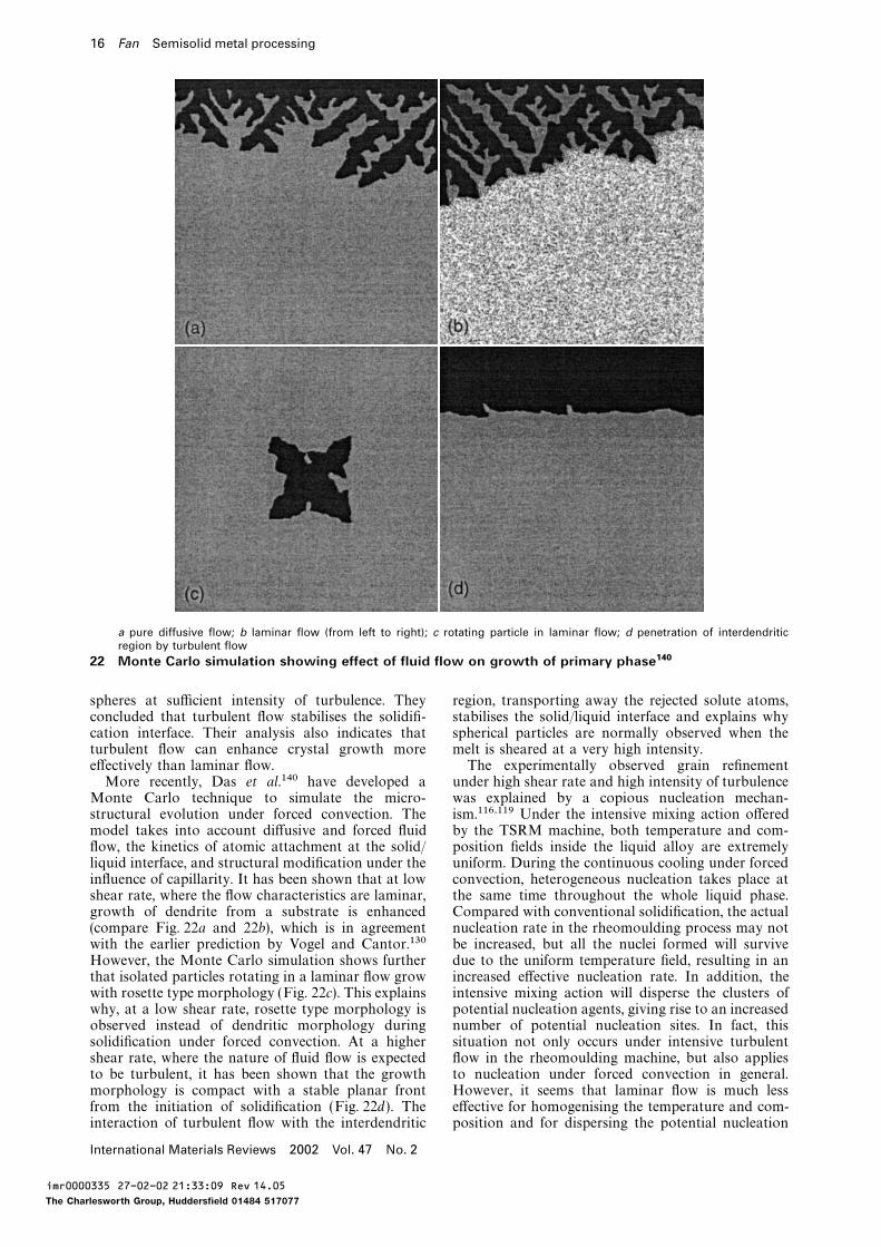
22 Monte Carlo simulation showing effect of fluid flow on growth of primary phase140
spheres at sufficient intensity of turbulence. They region, transporting away the rejected solute atoms,stabilises the solid/liquid interface and explains whyconcluded that turbulent flow stabilises the solidifi-
cation interface. Their analysis also indicates that spherical particles are normally observed when themelt is sheared at a very high intensity.turbulent flow can enhance crystal growth more
effectively than laminar flow. The experimentally observed grain refinementunder high shear rate and high intensity of turbulenceMore recently, Das et al.140 have developed a
Monte Carlo technique to simulate the micro- was explained by a copious nucleation mechan-ism.116,119 Under the intensive mixing action offeredstructural evolution under forced convection. The
model takes into account diffusive and forced fluid by the TSRM machine, both temperature and com-position fields inside the liquid alloy are extremelyflow, the kinetics of atomic attachment at the solid/
liquid interface, and structural modification under the uniform. During the continuous cooling under forcedconvection, heterogeneous nucleation takes place atinfluence of capillarity. It has been shown that at low
shear rate, where the flow characteristics are laminar, the same time throughout the whole liquid phase.Compared with conventional solidification, the actualgrowth of dendrite from a substrate is enhanced
(compare Fig. 22a and 22b), which is in agreement nucleation rate in the rheomoulding process may notbe increased, but all the nuclei formed will survivewith the earlier prediction by Vogel and Cantor.130
However, the Monte Carlo simulation shows further due to the uniform temperature field, resulting in anincreased effective nucleation rate. In addition, thethat isolated particles rotating in a laminar flow grow
with rosette type morphology (Fig. 22c). This explains intensive mixing action will disperse the clusters ofpotential nucleation agents, giving rise to an increasedwhy, at a low shear rate, rosette type morphology is
observed instead of dendritic morphology during number of potential nucleation sites. In fact, thissituation not only occurs under intensive turbulentsolidification under forced convection. At a higher
shear rate, where the nature of fluid flow is expected flow in the rheomoulding machine, but also appliesto nucleation under forced convection in general.to be turbulent, it has been shown that the growth
morphology is compact with a stable planar front However, it seems that laminar flow is much lesseffective for homogenising the temperature and com-from the initiation of solidification (Fig. 22d ). The
interaction of turbulent flow with the interdendritic position and for dispersing the potential nucleation
International Materials Reviews 2002 Vol. 47 No. 2
imr0000335 27-02-02 21:33:09 Rev 14.05
The Charlesworth Group, Huddersfield 01484 517077
Fan Semisolid metal processing 17
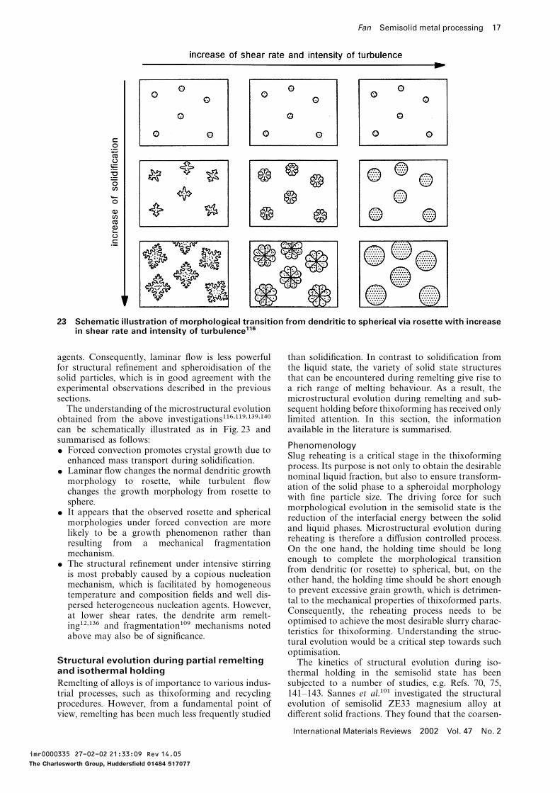
23 Schematic illustration of morphological transition from dendritic to spherical via rosette with increasein shear rate and intensity of turbulence116
agents. Consequently, laminar flow is less powerful than solidification. In contrast to solidification fromthe liquid state, the variety of solid state structuresfor structural refinement and spheroidisation of the
solid particles, which is in good agreement with the that can be encountered during remelting give rise toa rich range of melting behaviour. As a result, theexperimental observations described in the previous
sections. microstructural evolution during remelting and sub-sequent holding before thixoforming has received onlyThe understanding of the microstructural evolution
obtained from the above investigations116,119,139,140 limited attention. In this section, the informationavailable in the literature is summarised.can be schematically illustrated as in Fig. 23 and
summarised as follows:Phenomenology
$ Forced convection promotes crystal growth due toSlug reheating is a critical stage in the thixoforming
enhanced mass transport during solidification.process. Its purpose is not only to obtain the desirable
$ Laminar flow changes the normal dendritic growthnominal liquid fraction, but also to ensure transform-
morphology to rosette, while turbulent flowation of the solid phase to a spheroidal morphology
changes the growth morphology from rosette towith fine particle size. The driving force for such
sphere.morphological evolution in the semisolid state is the
$ It appears that the observed rosette and sphericalreduction of the interfacial energy between the solid
morphologies under forced convection are moreand liquid phases. Microstructural evolution during
likely to be a growth phenomenon rather thanreheating is therefore a diffusion controlled process.
resulting from a mechanical fragmentationOn the one hand, the holding time should be long
mechanism.enough to complete the morphological transition
$ The structural refinement under intensive stirringfrom dendritic (or rosette) to spherical, but, on the
is most probably caused by a copious nucleationother hand, the holding time should be short enough
mechanism, which is facilitated by homogeneousto prevent excessive grain growth, which is detrimen-
temperature and composition fields and well dis-tal to the mechanical properties of thixoformed parts.
persed heterogeneous nucleation agents. However,Consequently, the reheating process needs to be
at lower shear rates, the dendrite arm remelt-optimised to achieve the most desirable slurry charac-
ing12,136 and fragmentation109 mechanisms notedteristics for thixoforming. Understanding the struc-
above may also be of significance.tural evolution would be a critical step towards suchoptimisation.
Structural evolution during partial remelting The kinetics of structural evolution during iso-and isothermal holding thermal holding in the semisolid state has been
subjected to a number of studies, e.g. Refs. 70, 75,Remelting of alloys is of importance to various indus-trial processes, such as thixoforming and recycling 141–143. Sannes et al.101 investigated the structural
evolution of semisolid ZE33 magnesium alloy atprocedures. However, from a fundamental point ofview, remelting has been much less frequently studied different solid fractions. They found that the coarsen-
International Materials Reviews 2002 Vol. 47 No. 2
imr0000335 27-02-02 21:33:09 Rev 14.05
The Charlesworth Group, Huddersfield 01484 517077
18 Fan Semisolid metal processing
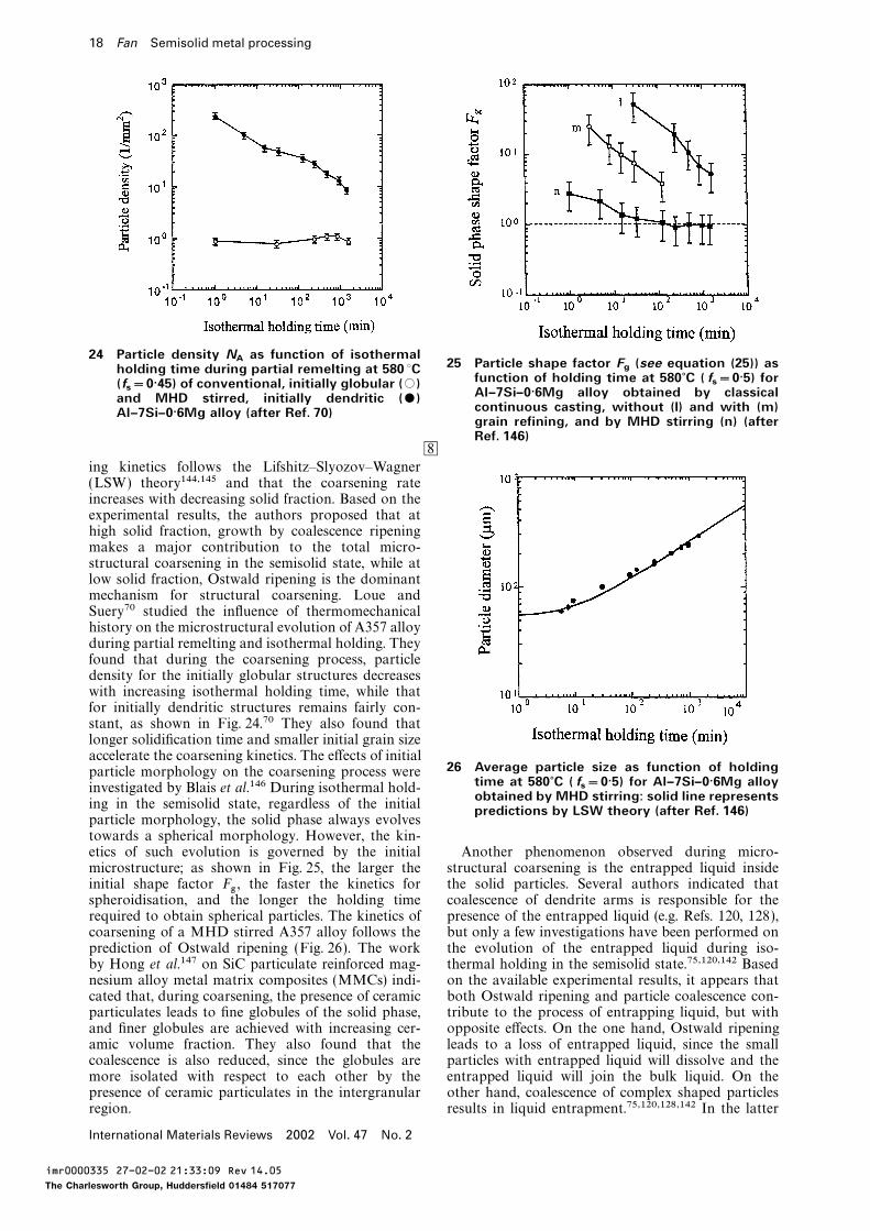
24 Particle density NAas function of isothermal
25 Particle shape factor Fg(see equation (25)) asholding time during partial remelting at 580 °C
function of holding time at 580?C ( fs=0·5) for(f
s=0·45) of conventional, initially globular (#)
Al–7Si–0·6Mg alloy obtained by classicaland MHD stirred, initially dendritic ($)continuous casting, without (l) and with (m)Al–7Si–0·6Mg alloy (after Ref. 70)grain refining, and by MHD stirring (n) (afterRef. 146)
8ing kinetics follows the Lifshitz–Slyozov–Wagner(LSW) theory144,145 and that the coarsening rateincreases with decreasing solid fraction. Based on theexperimental results, the authors proposed that athigh solid fraction, growth by coalescence ripeningmakes a major contribution to the total micro-structural coarsening in the semisolid state, while atlow solid fraction, Ostwald ripening is the dominantmechanism for structural coarsening. Loue andSuery70 studied the influence of thermomechanicalhistory on the microstructural evolution of A357 alloyduring partial remelting and isothermal holding. Theyfound that during the coarsening process, particledensity for the initially globular structures decreaseswith increasing isothermal holding time, while thatfor initially dendritic structures remains fairly con-stant, as shown in Fig. 24.70 They also found thatlonger solidification time and smaller initial grain sizeaccelerate the coarsening kinetics. The effects of initial
26 Average particle size as function of holdingparticle morphology on the coarsening process weretime at 580?C ( f
s=0·5) for Al–7Si–0·6Mg alloyinvestigated by Blais et al.146 During isothermal hold-
obtained by MHD stirring: solid line representsing in the semisolid state, regardless of the initial predictions by LSW theory (after Ref. 146)particle morphology, the solid phase always evolvestowards a spherical morphology. However, the kin-etics of such evolution is governed by the initial Another phenomenon observed during micro-
structural coarsening is the entrapped liquid insidemicrostructure; as shown in Fig. 25, the larger theinitial shape factor Fg , the faster the kinetics for the solid particles. Several authors indicated that
coalescence of dendrite arms is responsible for thespheroidisation, and the longer the holding timerequired to obtain spherical particles. The kinetics of presence of the entrapped liquid (e.g. Refs. 120, 128),
but only a few investigations have been performed oncoarsening of a MHD stirred A357 alloy follows theprediction of Ostwald ripening (Fig. 26). The work the evolution of the entrapped liquid during iso-
thermal holding in the semisolid state.75,120,142 Basedby Hong et al.147 on SiC particulate reinforced mag-nesium alloy metal matrix composites (MMCs) indi- on the available experimental results, it appears that
both Ostwald ripening and particle coalescence con-cated that, during coarsening, the presence of ceramicparticulates leads to fine globules of the solid phase, tribute to the process of entrapping liquid, but with
opposite effects. On the one hand, Ostwald ripeningand finer globules are achieved with increasing cer-amic volume fraction. They also found that the leads to a loss of entrapped liquid, since the small
particles with entrapped liquid will dissolve and thecoalescence is also reduced, since the globules aremore isolated with respect to each other by the entrapped liquid will join the bulk liquid. On the
other hand, coalescence of complex shaped particlespresence of ceramic particulates in the intergranularregion. results in liquid entrapment.75,120,128,142 In the latter
International Materials Reviews 2002 Vol. 47 No. 2
imr0000335 27-02-02 21:33:09 Rev 14.05
The Charlesworth Group, Huddersfield 01484 517077
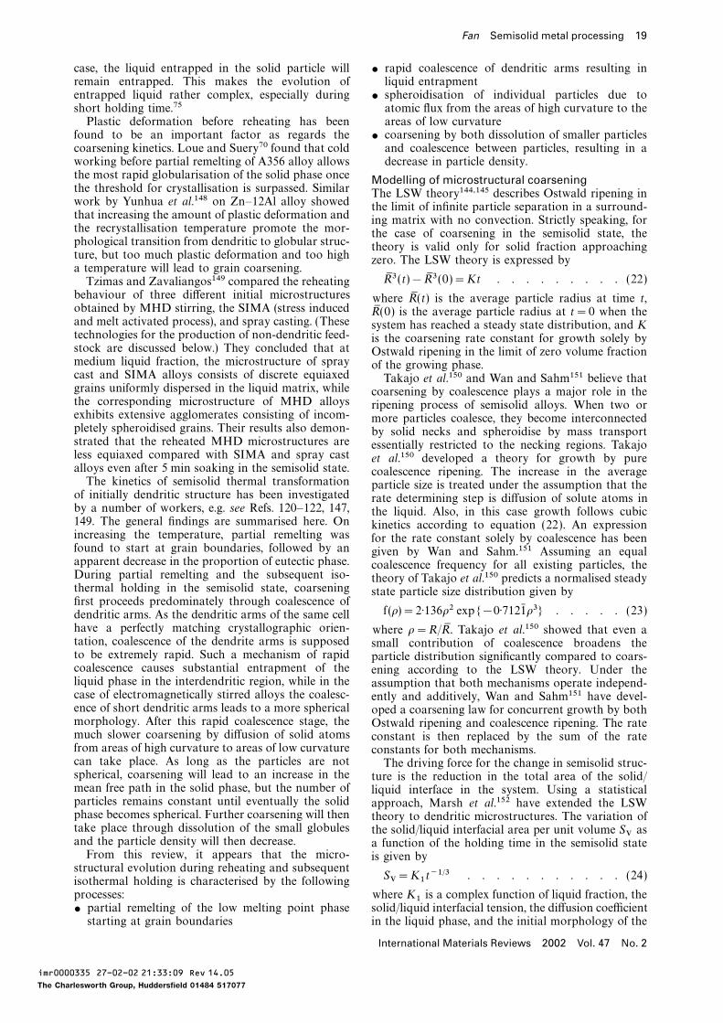
Fan Semisolid metal processing 19
case, the liquid entrapped in the solid particle will $ rapid coalescence of dendritic arms resulting inliquid entrapmentremain entrapped. This makes the evolution of
entrapped liquid rather complex, especially during $ spheroidisation of individual particles due toatomic flux from the areas of high curvature to theshort holding time.75
Plastic deformation before reheating has been areas of low curvature$ coarsening by both dissolution of smaller particlesfound to be an important factor as regards the
coarsening kinetics. Loue and Suery70 found that cold and coalescence between particles, resulting in adecrease in particle density.working before partial remelting of A356 alloy allows
the most rapid globularisation of the solid phase once Modelling of microstructural coarseningthe threshold for crystallisation is surpassed. Similar The LSW theory144,145 describes Ostwald ripening inwork by Yunhua et al.148 on Zn–12Al alloy showed the limit of infinite particle separation in a surround-that increasing the amount of plastic deformation and ing matrix with no convection. Strictly speaking, forthe recrystallisation temperature promote the mor- the case of coarsening in the semisolid state, thephological transition from dendritic to globular struc- theory is valid only for solid fraction approachingture, but too much plastic deformation and too high zero. The LSW theory is expressed bya temperature will lead to grain coarsening.
R9 3 (t)−R9 3(0)=Kt . . . . . . . . . (22)Tzimas and Zavaliangos149 compared the reheatingbehaviour of three different initial microstructures where R9 (t) is the average particle radius at time t,obtained by MHD stirring, the SIMA (stress induced R9 (0) is the average particle radius at t=0 when theand melt activated process), and spray casting. (These system has reached a steady state distribution, and Ktechnologies for the production of non-dendritic feed- is the coarsening rate constant for growth solely bystock are discussed below.) They concluded that at Ostwald ripening in the limit of zero volume fractionmedium liquid fraction, the microstructure of spray of the growing phase.cast and SIMA alloys consists of discrete equiaxed Takajo et al.150 and Wan and Sahm151 believe thatgrains uniformly dispersed in the liquid matrix, while coarsening by coalescence plays a major role in thethe corresponding microstructure of MHD alloys ripening process of semisolid alloys. When two orexhibits extensive agglomerates consisting of incom- more particles coalesce, they become interconnectedpletely spheroidised grains. Their results also demon- by solid necks and spheroidise by mass transportstrated that the reheated MHD microstructures are essentially restricted to the necking regions. Takajoless equiaxed compared with SIMA and spray cast et al.150 developed a theory for growth by purealloys even after 5 min soaking in the semisolid state. coalescence ripening. The increase in the averageThe kinetics of semisolid thermal transformation particle size is treated under the assumption that the
of initially dendritic structure has been investigated rate determining step is diffusion of solute atoms inby a number of workers, e.g. see Refs. 120–122, 147, the liquid. Also, in this case growth follows cubic149. The general findings are summarised here. On kinetics according to equation (22). An expressionincreasing the temperature, partial remelting was for the rate constant solely by coalescence has beenfound to start at grain boundaries, followed by an given by Wan and Sahm.151 Assuming an equalapparent decrease in the proportion of eutectic phase. coalescence frequency for all existing particles, theDuring partial remelting and the subsequent iso- theory of Takajo et al.150 predicts a normalised steadythermal holding in the semisolid state, coarsening state particle size distribution given byfirst proceeds predominately through coalescence of
f (r)=2·136r2 exp{−0·7121:r3} . . . . . (23)dendritic arms. As the dendritic arms of the same cellhave a perfectly matching crystallographic orien- where r=R/R9 . Takajo et al.150 showed that even atation, coalescence of the dendrite arms is supposed small contribution of coalescence broadens theto be extremely rapid. Such a mechanism of rapid particle distribution significantly compared to coars-coalescence causes substantial entrapment of the ening according to the LSW theory. Under theliquid phase in the interdendritic region, while in the assumption that both mechanisms operate independ-case of electromagnetically stirred alloys the coalesc- ently and additively, Wan and Sahm151 have devel-ence of short dendritic arms leads to a more spherical oped a coarsening law for concurrent growth by bothmorphology. After this rapid coalescence stage, the Ostwald ripening and coalescence ripening. The ratemuch slower coarsening by diffusion of solid atoms constant is then replaced by the sum of the ratefrom areas of high curvature to areas of low curvature constants for both mechanisms.can take place. As long as the particles are not The driving force for the change in semisolid struc-spherical, coarsening will lead to an increase in the ture is the reduction in the total area of the solid/mean free path in the solid phase, but the number of liquid interface in the system. Using a statisticalparticles remains constant until eventually the solid approach, Marsh et al.152 have extended the LSWphase becomes spherical. Further coarsening will then theory to dendritic microstructures. The variation oftake place through dissolution of the small globules the solid/liquid interfacial area per unit volume SV asand the particle density will then decrease. a function of the holding time in the semisolid stateFrom this review, it appears that the micro- is given by
structural evolution during reheating and subsequentSV=K1t−1/3 . . . . . . . . . . . (24)isothermal holding is characterised by the following
processes: where K1 is a complex function of liquid fraction, thesolid/liquid interfacial tension, the diffusion coefficient$ partial remelting of the low melting point phase
starting at grain boundaries in the liquid phase, and the initial morphology of the
International Materials Reviews 2002 Vol. 47 No. 2
imr0000335 27-02-02 21:33:09 Rev 14.05
The Charlesworth Group, Huddersfield 01484 517077
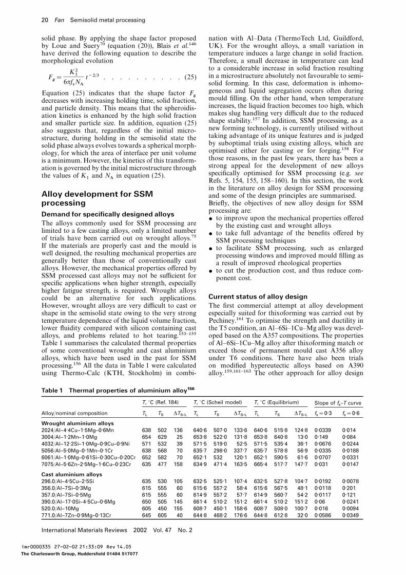
20 Fan Semisolid metal processing
solid phase. By applying the shape factor proposed nation with Al–Data (ThermoTech Ltd, Guildford,UK). For the wrought alloys, a small variation inby Loue and Suery70 (equation (20)), Blais et al.146
have derived the following equation to describe the temperature induces a large change in solid fraction.Therefore, a small decrease in temperature can leadmorphological evolutionto a considerable increase in solid fraction resultingin a microstructure absolutely not favourable to semi-F
g=
K216pfsNAt−2/3 . . . . . . . . . . (25)
solid forming. In this case, deformation is inhomo-geneous and liquid segregation occurs often duringEquation (25) indicates that the shape factor Fg mould filling. On the other hand, when temperaturedecreases with increasing holding time, solid fraction,increases, the liquid fraction becomes too high, whichand particle density. This means that the spheroidis-makes slug handling very difficult due to the reducedation kinetics is enhanced by the high solid fractionshape stability.157 In addition, SSM processing, as aand smaller particle size. In addition, equation (25)new forming technology, is currently utilised withoutalso suggests that, regardless of the initial micro-taking advantage of its unique features and is judgedstructure, during holding in the semisolid state theby suboptimal trials using existing alloys, which aresolid phase always evolves towards a spherical morph-optimised either for casting or for forging.158 Forology, for which the area of interface per unit volumethose reasons, in the past few years, there has been ais a minimum. However, the kinetics of this transform-strong appeal for the development of new alloysation is governed by the initial microstructure throughspecifically optimised for SSM processing (e.g. seethe values of K1 and NA in equation (25). Refs. 5, 154, 155, 158–160). In this section, the workin the literature on alloy design for SSM processing
Alloy development for SSM and some of the design principles are summarised.Briefly, the objectives of new alloy design for SSMprocessingprocessing are:Demand for specifically designed alloys$ to improve upon the mechanical properties offered
The alloys commonly used for SSM processing are by the existing cast and wrought alloyslimited to a few casting alloys, only a limited number
$ to take full advantage of the benefits offered byof trials have been carried out on wrought alloys.75 SSM processing techniquesIf the materials are properly cast and the mould is
$ to facilitate SSM processing, such as enlargedwell designed, the resulting mechanical properties are processing windows and improved mould filling asgenerally better than those of conventionally cast a result of improved rheological propertiesalloys. However, the mechanical properties offered by
$ to cut the production cost, and thus reduce com-SSM processed cast alloys may not be sufficient for ponent cost.specific applications when higher strength, especiallyhigher fatigue strength, is required. Wrought alloys
Current status of alloy designcould be an alternative for such applications.However, wrought alloys are very difficult to cast or The first commercial attempt at alloy development
especially suited for thixoforming was carried out byshape in the semisolid state owing to the very strongtemperature dependence of the liquid volume fraction, Pechiney.161 To optimise the strength and ductility in
the T5 condition, an Al–6Si–1Cu–Mg alloy was devel-lower fluidity compared with silicon containing castalloys, and problems related to hot tearing.153–155 oped based on the A357 compositions. The properties
of Al–6Si–1Cu–Mg alloy after thixoforming match orTable 1 summarises the calculated thermal propertiesof some conventional wrought and cast aluminium exceed those of permanent mould cast A356 alloy
under T6 conditions. There have also been trialsalloys, which have been used in the past for SSMprocessing.156 All the data in Table 1 were calculated on modified hypereutectic alloys based on A390
alloy.159,161–163 The other approach for alloy designusing Thermo-Calc (KTH, Stockholm) in combi-
Table 1 Thermal properties of aluminium alloy156
T, °C (Ref. 184) T, °C (Scheil model) T, °C (Equilibrium) Slope of fs–T curve
Alloy/nominal composition TL
TS
DTS–L
TL
TS
DTS–L
TL
TS
DTS–L
fs=0·3 f
s=0·6
Wrought aluminium alloys2024/Al–4·4Cu–1·5Mg–0·6Mn 638 502 136 640·6 507·0 133·6 640·6 515·8 124·8 0·0339 0·0143004/Al–1·2Mn–1·0Mg 654 629 25 653·8 522·0 131·8 653·8 640·8 13·0 0·149 0·0844032/Al–12·2Si–1·0Mg–0·9Cu–0·9Ni 571 532 39 571·5 519·0 52·5 571·5 535·4 36·1 0·0676 0·02445056/Al–5·0Mg–0·1Mn–0·1Cr 638 568 70 635·7 298·0 337·7 635·7 578·8 56·9 0·0335 0·01886061/Al–1·0Mg–0·61Si–0·30Cu–0·20Cr 652 582 70 652·1 532 120·1 652·1 590·5 61·6 0·0707 0·03317075/Al–5·6Zn–2·5Mg–1·6Cu–0·23Cr 635 477 158 634·9 471·4 163·5 665·4 517·7 147·7 0·031 0·0147
Cast aluminium alloys296.0/Al–4·5Cu–2·5Si 635 530 105 632·5 525·1 107·4 632·5 527·8 104·7 0·0192 0·0078356.0/Al–7Si–0·3Mg 615 555 60 615·6 557·2 58·4 615·6 567·5 48·1 0·0118 0·201357.0/Al–7Si–0·5Mg 615 555 60 614·9 557·2 57·7 614·9 560·7 54·2 0·0117 0·121390.0/Al–17·0Si–4·5Cu–0·6Mg 650 505 145 661·4 510·2 151·2 661·4 510·2 151·2 0·06 0·0241520.0/Al–10Mg 605 450 155 608·7 450·1 158·6 608·7 508·0 100·7 0·016 0·0094771.0/Al–7Zn–0·9Mg–0·13Cr 645 605 40 644·8 468·2 176·6 644·8 612·8 32·0 0·0586 0·0349
International Materials Reviews 2002 Vol. 47 No. 2
imr0000335 27-02-02 21:33:09 Rev 14.05
The Charlesworth Group, Huddersfield 01484 517077
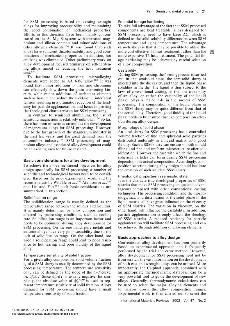
Fan Semisolid metal processing 21
for SSM processing is based on existing wrought Potential for age hardeningTo take full advantage of the fact that SSM processedalloys for improving processability and maintaining
the good combination of mechanical properties. components are heat treatable, alloys designed forSSM processing need to have large DC, which isEfforts in this direction have been mainly concen-
trated on the Al–Mg–Si system with increased mag- defined as the solid solubility difference between SSMtemperature and aging temperature. The advantagenesium and silicon contents and minor additions of
other alloying elements.154 It was found that such of such alloys is that it may be possible to utilise themore cost effective T5 heat treatment, rather than thealloys have sufficient thixoformability and good com- 9
binations of mechanical properties. In addition, hot more expensive T6 heat treatment. The potential forage hardening may be achieved by careful selectioncracking was eliminated. Other preliminary work on
alloy development focused primarily on self-harden- of alloy composition.ing alloys aimed at reducing the heat treatment Castabilitycost.154
During SSM processing, the forming process is carriedTo facilitate SSM processing, microalloying
out in the semisolid state, the semisolid slurry iselements were added to AA 6082 alloy.100 It was
injected into the die cavity, and then the liquid phasefound that minor additions of iron and chromium
solidifies in the die. The liquid is thus subject to thecan effectively slow down the grain coarsening kin-
laws of conventional casting, so that the castabilityetics, while minor additions of surfactant elements
of an alloy, or rather the castability of the liquidsuch as barium can reduce the solid/liquid interfacial
phase, plays a major role in the success of SSMtension resulting in a dramatic reduction of the tend-
processing. The composition of the liquid phase inency for particle agglomeration, and hence improving
the SSM slurry may be quite different from that ofthe rheological characteristics for SSM processing.
the actual alloy. Therefore, good fluidity of the liquidIn contrast to semisolid aluminium, the use of
phase needs to be ensured through composition selec-semisolid magnesium is relatively unknown.164 So far,
tion during alloy design.there has been no serious attempt at the development
Morphology of solid phaseof magnesium alloys for SSM processing. However,An ideal slurry for SSM processing has a controlleddue to the fast growth of the magnesium industry involume fraction of fine and spherical solid particlesthe past few years, and the great demand from thedistributed uniformly in a liquid matrix with goodautomobile industry,165 SSM processing of mag-fluidity. Such a SSM slurry can ensure smooth mouldnesium alloys and associated alloy development couldfilling and fine and uniform microstructure after sol-be an exciting area for future research.idification. However, the ease with which the fine andspherical particles can form during SSM processing
Basic considerations for alloy development depends on the actual composition. Accordingly, com-To achieve the above mentioned objectives for alloy position selection during alloy design should facilitatedesign specifically for SSM processing, a number of the creation of such an ideal SSM slurry.scientific and technological factors need to be consid- Rheological properties in semisolid stateered. Based on the prior experimental work, and the
It is the characteristic rheological properties of SSMrecent analysis by Witulski et al.,153 Atkinson et al.,155
slurries that make SSM processing unique and advan-and Liu and Fan,166 such basic considerations are
tageous compared with other conventional castingsummarised in this section.
techniques. The processing condition, and the morph-ology, size, and distribution of the solid phase in theSolidification rangeliquid matrix, all have great influence on the viscosityThe solidification range is usually defined as theof SSM slurries. The variation in viscosity, on thetemperature range between the solidus and liquidus.other hand, will influence the castability. In addition,It is mainly determined by alloy composition andparticle agglomeration strongly affects the rheologyaffected by processing conditions, such as coolingof SSM slurries. A reduced tendency for particlerate. Solidification range is an important factor andagglomeration will facilitate SSM processing and canneeds to be optimised during alloy development forbe achieved through addition of alloying elements.SSM processing. On the one hand, pure metals and
eutectic alloys have very poor castability due to thelack of solidification range. On the other hand, too Basic approaches to alloy designwide a solidification range could lead to poor resist-
Conventional alloy development has been primarilyance to hot tearing and poor fluidity of the liquidbased on experimental approach and is frequentlyalloy.performed by the trial and error method. However,alloy development for SSM processing need not beTemperature sensitivity of solid fraction
For a given alloy composition, solid volume fraction from scratch; the vast information on the developmentof both cast and wrought alloys can be utilised. Morevs of a SSM slurry is usually determined by the SSM
processing temperature. The temperature sensitivity importantly, the Calphad approach, combined withan appropriate thermodynamic database, can be aof vs can be defined by the slope of the fs–T curve,
i.e. dfs/dT. Since dfs/dT is usually negative, for sim- very powerful tool to guide the development of newalloys. Generally, thermodynamic calculations canplicity, the absolute value of dfs/dT is used to rep-
resent temperature sensitivity of solid fraction. Alloys be used to select the major alloying elements andto narrow down the alloy composition ranges.designed for SSM processing should have a small
temperature sensitivity of solid fraction. Experimental work is then carried out to select the
International Materials Reviews 2002 Vol. 47 No. 2
imr0000335 27-02-02 21:33:09 Rev 14.05
The Charlesworth Group, Huddersfield 01484 517077
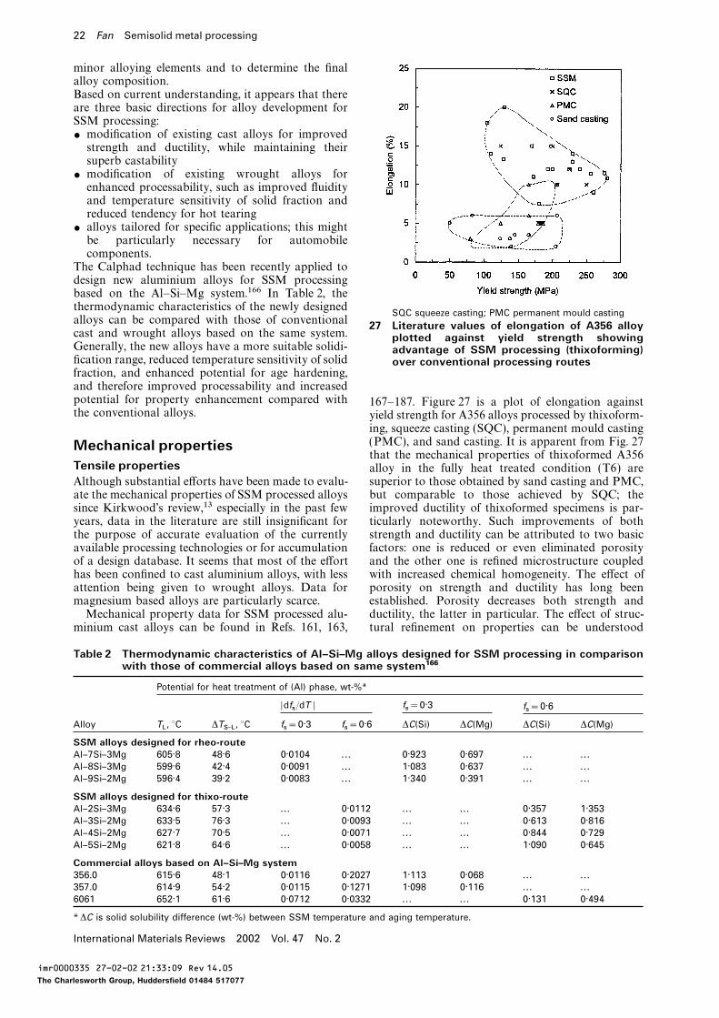
22 Fan Semisolid metal processing
minor alloying elements and to determine the finalalloy composition.Based on current understanding, it appears that thereare three basic directions for alloy development forSSM processing:$ modification of existing cast alloys for improvedstrength and ductility, while maintaining theirsuperb castability
$ modification of existing wrought alloys forenhanced processability, such as improved fluidityand temperature sensitivity of solid fraction andreduced tendency for hot tearing
$ alloys tailored for specific applications; this mightbe particularly necessary for automobilecomponents.
The Calphad technique has been recently applied todesign new aluminium alloys for SSM processingbased on the Al–Si–Mg system.166 In Table 2, thethermodynamic characteristics of the newly designed
SQC squeeze casting; PMC permanent mould castingalloys can be compared with those of conventional 27 Literature values of elongation of A356 alloycast and wrought alloys based on the same system. plotted against yield strength showingGenerally, the new alloys have a more suitable solidi- advantage of SSM processing (thixoforming)fication range, reduced temperature sensitivity of solid over conventional processing routesfraction, and enhanced potential for age hardening,and therefore improved processability and increasedpotential for property enhancement compared with 167–187. Figure 27 is a plot of elongation againstthe conventional alloys. yield strength for A356 alloys processed by thixoform-
ing, squeeze casting (SQC), permanent mould casting(PMC), and sand casting. It is apparent from Fig. 27Mechanical propertiesthat the mechanical properties of thixoformed A356
Tensile properties alloy in the fully heat treated condition (T6) aresuperior to those obtained by sand casting and PMC,Although substantial efforts have been made to evalu-
ate the mechanical properties of SSM processed alloys but comparable to those achieved by SQC; theimproved ductility of thixoformed specimens is par-since Kirkwood’s review,13 especially in the past few
years, data in the literature are still insignificant for ticularly noteworthy. Such improvements of bothstrength and ductility can be attributed to two basicthe purpose of accurate evaluation of the currently
available processing technologies or for accumulation factors: one is reduced or even eliminated porosityand the other one is refined microstructure coupledof a design database. It seems that most of the effort
has been confined to cast aluminium alloys, with less with increased chemical homogeneity. The effect ofporosity on strength and ductility has long beenattention being given to wrought alloys. Data for
magnesium based alloys are particularly scarce. established. Porosity decreases both strength andductility, the latter in particular. The effect of struc-Mechanical property data for SSM processed alu-
minium cast alloys can be found in Refs. 161, 163, tural refinement on properties can be understood
Table 2 Thermodynamic characteristics of Al–Si–Mg alloys designed for SSM processing in comparisonwith those of commercial alloys based on same system166
Potential for heat treatment of (Al) phase, wt-%*
|dfs/dT | f
s=0·3 f
s=0·6
Alloy TL, °C DT
S–L, °C f
s=0·3 f
s=0·6 DC(Si) DC(Mg) DC(Si) DC(Mg)
SSM alloys designed for rheo-routeAl–7Si–3Mg 605·8 48·6 0·0104 ... 0·923 0·697 ... . . .Al–8Si–3Mg 599·6 42·4 0·0091 ... 1·083 0·637 ... . . .Al–9Si–2Mg 596·4 39·2 0·0083 ... 1·340 0·391 ... . . .
SSM alloys designed for thixo-routeAl–2Si–3Mg 634·6 57·3 ... 0·0112 ... . . . 0·357 1·353Al–3Si–2Mg 633·5 76·3 ... 0·0093 ... . . . 0·613 0·816Al–4Si–2Mg 627·7 70·5 ... 0·0071 ... . . . 0·844 0·729Al–5Si–2Mg 621·8 64·6 ... 0·0058 ... . . . 1·090 0·645
Commercial alloys based on Al–Si–Mg system356.0 615·6 48·1 0·0116 0·2027 1·113 0·068 ... . . .357.0 614·9 54·2 0·0115 0·1271 1·098 0·116 ... . . .6061 652·1 61·6 0·0712 0·0332 ... . . . 0·131 0·494
*DC is solid solubility difference (wt-%) between SSM temperature and aging temperature.
International Materials Reviews 2002 Vol. 47 No. 2
imr0000335 27-02-02 21:33:09 Rev 14.05
The Charlesworth Group, Huddersfield 01484 517077
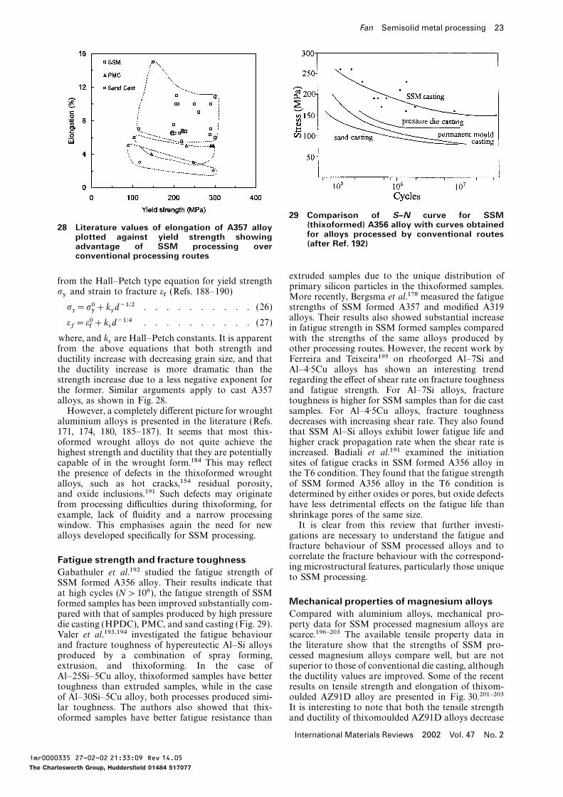
Fan Semisolid metal processing 23
29 Comparison of S–N curve for SSM(thixoformed) A356 alloy with curves obtained28 Literature values of elongation of A357 alloyfor alloys processed by conventional routesplotted against yield strength showing(after Ref. 192)advantage of SSM processing over
conventional processing routes
extruded samples due to the unique distribution offrom the Hall–Petch type equation for yield strength
primary silicon particles in the thixoformed samples.sy and strain to fracture ef (Refs. 188–190) More recently, Bergsma et al.178 measured the fatigue
strengths of SSM formed A357 and modified A319sy=s0y+kyd−1/2 . . . . . . . . . . (26)
alloys. Their results also showed substantial increaseef=e0f+ked−1/4 . . . . . . . . . . (27)
in fatigue strength in SSM formed samples comparedwith the strengths of the same alloys produced bywhere, and k
eare Hall–Petch constants. It is apparent
from the above equations that both strength and other processing routes. However, the recent work byFerreira and Teixeira195 on rheoforged Al–7Si andductility increase with decreasing grain size, and that
the ductility increase is more dramatic than the Al–4·5Cu alloys has shown an interesting trendregarding the effect of shear rate on fracture toughnessstrength increase due to a less negative exponent for
the former. Similar arguments apply to cast A357 and fatigue strength. For Al–7Si alloys, fracturetoughness is higher for SSM samples than for die castalloys, as shown in Fig. 28.
However, a completely different picture for wrought samples. For Al–4·5Cu alloys, fracture toughnessdecreases with increasing shear rate. They also foundaluminium alloys is presented in the literature (Refs.
171, 174, 180, 185–187). It seems that most thix- that SSM Al–Si alloys exhibit lower fatigue life andhigher crack propagation rate when the shear rate isoformed wrought alloys do not quite achieve the
highest strength and ductility that they are potentially increased. Badiali et al.191 examined the initiationsites of fatigue cracks in SSM formed A356 alloy incapable of in the wrought form.184 This may reflect
the presence of defects in the thixoformed wrought the T6 condition. They found that the fatigue strengthof SSM formed A356 alloy in the T6 condition isalloys, such as hot cracks,154 residual porosity,
and oxide inclusions.191 Such defects may originate determined by either oxides or pores, but oxide defectshave less detrimental effects on the fatigue life thanfrom processing difficulties during thixoforming, for
example, lack of fluidity and a narrow processing shrinkage pores of the same size.It is clear from this review that further investi-window. This emphasises again the need for new
alloys developed specifically for SSM processing. gations are necessary to understand the fatigue andfracture behaviour of SSM processed alloys and tocorrelate the fracture behaviour with the correspond-Fatigue strength and fracture toughnessing microstructural features, particularly those unique
Gabathuler et al.192 studied the fatigue strength ofto SSM processing.
SSM formed A356 alloy. Their results indicate thatat high cycles (N>106 ), the fatigue strength of SSM
Mechanical properties of magnesium alloysformed samples has been improved substantially com-pared with that of samples produced by high pressure Compared with aluminium alloys, mechanical pro-
perty data for SSM processed magnesium alloys aredie casting (HPDC), PMC, and sand casting (Fig. 29).Valer et al.193,194 investigated the fatigue behaviour scarce.196–203 The available tensile property data in
the literature show that the strengths of SSM pro-and fracture toughness of hypereutectic Al–Si alloysproduced by a combination of spray forming, cessed magnesium alloys compare well, but are not
superior to those of conventional die casting, althoughextrusion, and thixoforming. In the case ofAl–25Si–5Cu alloy, thixoformed samples have better the ductility values are improved. Some of the recent
results on tensile strength and elongation of thixom-toughness than extruded samples, while in the caseof Al–30Si–5Cu alloy, both processes produced simi- oulded AZ91D alloy are presented in Fig. 30.201–203
It is interesting to note that both the tensile strengthlar toughness. The authors also showed that thix-oformed samples have better fatigue resistance than and ductility of thixomoulded AZ91D alloys decrease
International Materials Reviews 2002 Vol. 47 No. 2
imr0000335 27-02-02 21:33:09 Rev 14.05
The Charlesworth Group, Huddersfield 01484 517077
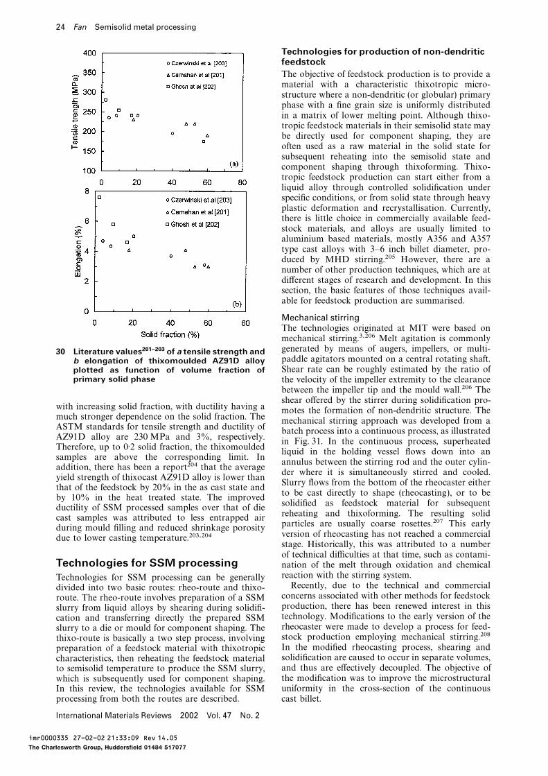
24 Fan Semisolid metal processing
Technologies for production of non-dendriticfeedstockThe objective of feedstock production is to provide amaterial with a characteristic thixotropic micro-structure where a non-dendritic (or globular) primaryphase with a fine grain size is uniformly distributedin a matrix of lower melting point. Although thixo-tropic feedstock materials in their semisolid state maybe directly used for component shaping, they areoften used as a raw material in the solid state forsubsequent reheating into the semisolid state andcomponent shaping through thixoforming. Thixo-tropic feedstock production can start either from aliquid alloy through controlled solidification underspecific conditions, or from solid state through heavyplastic deformation and recrystallisation. Currently,there is little choice in commercially available feed-stock materials, and alloys are usually limited toaluminium based materials, mostly A356 and A357type cast alloys with 3–6 inch billet diameter, pro-duced by MHD stirring.205 However, there are anumber of other production techniques, which are atdifferent stages of research and development. In thissection, the basic features of those techniques avail-able for feedstock production are summarised.
Mechanical stirringThe technologies originated at MIT were based onmechanical stirring.3,206 Melt agitation is commonlygenerated by means of augers, impellers, or multi-30 Literature values201–203 of a tensile strength andpaddle agitators mounted on a central rotating shaft.b elongation of thixomoulded AZ91D alloyShear rate can be roughly estimated by the ratio ofplotted as function of volume fraction of
primary solid phase the velocity of the impeller extremity to the clearancebetween the impeller tip and the mould wall.206 Theshear offered by the stirrer during solidification pro-
with increasing solid fraction, with ductility having a motes the formation of non-dendritic structure. Themuch stronger dependence on the solid fraction. The mechanical stirring approach was developed from aASTM standards for tensile strength and ductility of batch process into a continuous process, as illustratedAZ91D alloy are 230 MPa and 3%, respectively. in Fig. 31. In the continuous process, superheatedTherefore, up to 0·2 solid fraction, the thixomoulded
liquid in the holding vessel flows down into ansamples are above the corresponding limit. In
annulus between the stirring rod and the outer cylin-addition, there has been a report204 that the average
der where it is simultaneously stirred and cooled.yield strength of thixocast AZ91D alloy is lower than
Slurry flows from the bottom of the rheocaster eitherthat of the feedstock by 20% in the as cast state and
to be cast directly to shape (rheocasting), or to beby 10% in the heat treated state. The improved
solidified as feedstock material for subsequentductility of SSM processed samples over that of diereheating and thixoforming. The resulting solidcast samples was attributed to less entrapped airparticles are usually coarse rosettes.207 This earlyduring mould filling and reduced shrinkage porosityversion of rheocasting has not reached a commercialdue to lower casting temperature.203,204stage. Historically, this was attributed to a numberof technical difficulties at that time, such as contami-
Technologies for SSM processing nation of the melt through oxidation and chemicalreaction with the stirring system.Technologies for SSM processing can be generallyRecently, due to the technical and commercialdivided into two basic routes: rheo-route and thixo-concerns associated with other methods for feedstockroute. The rheo-route involves preparation of a SSMproduction, there has been renewed interest in thisslurry from liquid alloys by shearing during solidifi-technology. Modifications to the early version of thecation and transferring directly the prepared SSMrheocaster were made to develop a process for feed-slurry to a die or mould for component shaping. Thestock production employing mechanical stirring.208thixo-route is basically a two step process, involvingIn the modified rheocasting process, shearing andpreparation of a feedstock material with thixotropicsolidification are caused to occur in separate volumes,characteristics, then reheating the feedstock materialand thus are effectively decoupled. The objective ofto semisolid temperature to produce the SSM slurry,the modification was to improve the microstructuralwhich is subsequently used for component shaping.uniformity in the cross-section of the continuousIn this review, the technologies available for SSM
processing from both the routes are described. cast billet.
International Materials Reviews 2002 Vol. 47 No. 2
imr0000335 27-02-02 21:33:09 Rev 14.05
The Charlesworth Group, Huddersfield 01484 517077
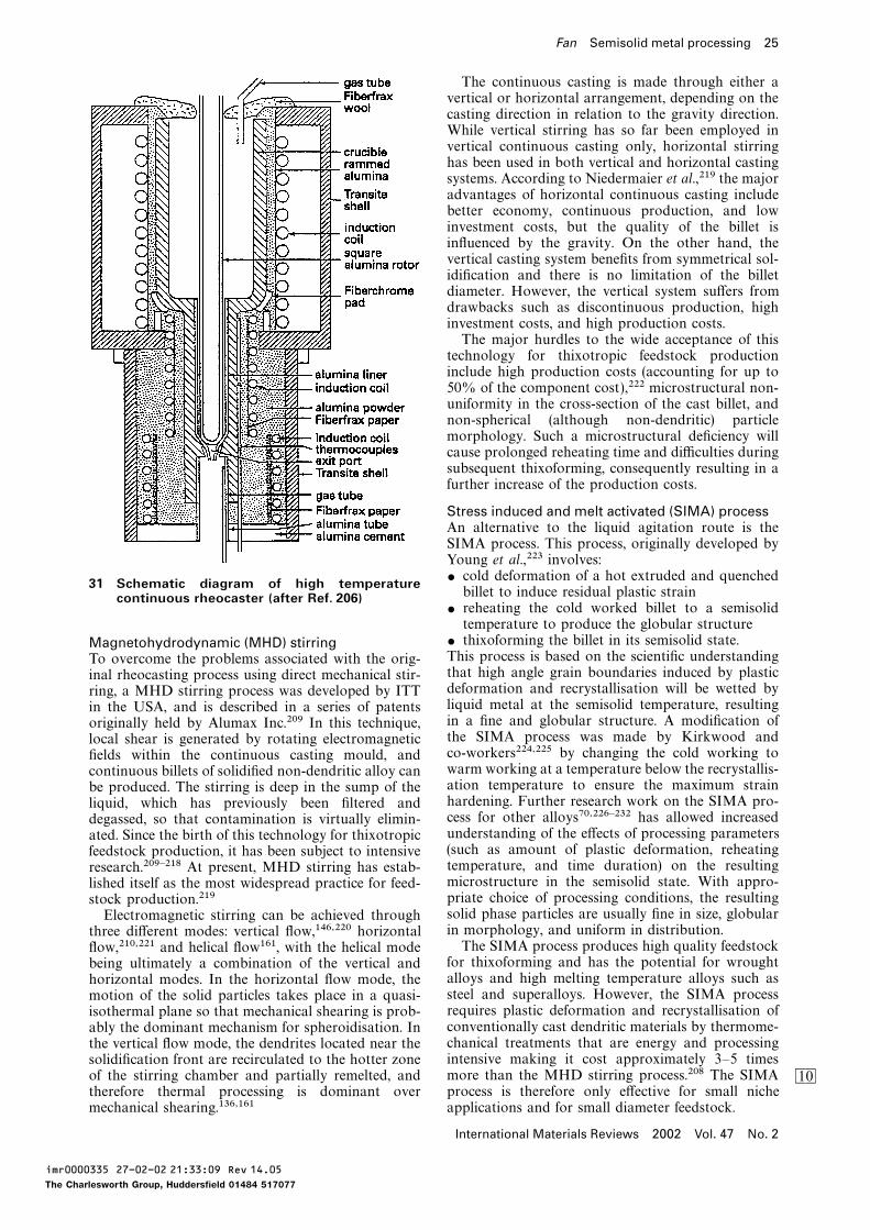
Fan Semisolid metal processing 25
The continuous casting is made through either avertical or horizontal arrangement, depending on thecasting direction in relation to the gravity direction.While vertical stirring has so far been employed invertical continuous casting only, horizontal stirringhas been used in both vertical and horizontal castingsystems. According to Niedermaier et al.,219 the majoradvantages of horizontal continuous casting includebetter economy, continuous production, and lowinvestment costs, but the quality of the billet isinfluenced by the gravity. On the other hand, thevertical casting system benefits from symmetrical sol-idification and there is no limitation of the billetdiameter. However, the vertical system suffers fromdrawbacks such as discontinuous production, highinvestment costs, and high production costs.The major hurdles to the wide acceptance of thistechnology for thixotropic feedstock productioninclude high production costs (accounting for up to50% of the component cost),222 microstructural non-uniformity in the cross-section of the cast billet, andnon-spherical (although non-dendritic) particlemorphology. Such a microstructural deficiency willcause prolonged reheating time and difficulties duringsubsequent thixoforming, consequently resulting in afurther increase of the production costs.
Stress induced and melt activated (SIMA) processAn alternative to the liquid agitation route is theSIMA process. This process, originally developed byYoung et al.,223 involves:$ cold deformation of a hot extruded and quenched31 Schematic diagram of high temperaturebillet to induce residual plastic straincontinuous rheocaster (after Ref. 206)
$ reheating the cold worked billet to a semisolidtemperature to produce the globular structure
$ thixoforming the billet in its semisolid state.Magnetohydrodynamic (MHD) stirringThis process is based on the scientific understandingTo overcome the problems associated with the orig-that high angle grain boundaries induced by plasticinal rheocasting process using direct mechanical stir-deformation and recrystallisation will be wetted byring, a MHD stirring process was developed by ITTliquid metal at the semisolid temperature, resultingin the USA, and is described in a series of patentsin a fine and globular structure. A modification oforiginally held by Alumax Inc.209 In this technique,the SIMA process was made by Kirkwood andlocal shear is generated by rotating electromagneticco-workers224,225 by changing the cold working tofields within the continuous casting mould, andwarm working at a temperature below the recrystallis-continuous billets of solidified non-dendritic alloy canation temperature to ensure the maximum strainbe produced. The stirring is deep in the sump of thehardening. Further research work on the SIMA pro-liquid, which has previously been filtered andcess for other alloys70,226–232 has allowed increaseddegassed, so that contamination is virtually elimin-understanding of the effects of processing parametersated. Since the birth of this technology for thixotropic(such as amount of plastic deformation, reheatingfeedstock production, it has been subject to intensivetemperature, and time duration) on the resultingresearch.209–218 At present, MHD stirring has estab-microstructure in the semisolid state. With appro-lished itself as the most widespread practice for feed-priate choice of processing conditions, the resultingstock production.219solid phase particles are usually fine in size, globularElectromagnetic stirring can be achieved throughin morphology, and uniform in distribution.three different modes: vertical flow,146,220 horizontalThe SIMA process produces high quality feedstockflow,210,221 and helical flow161, with the helical mode
for thixoforming and has the potential for wroughtbeing ultimately a combination of the vertical andalloys and high melting temperature alloys such ashorizontal modes. In the horizontal flow mode, thesteel and superalloys. However, the SIMA processmotion of the solid particles takes place in a quasi-requires plastic deformation and recrystallisation ofisothermal plane so that mechanical shearing is prob-conventionally cast dendritic materials by thermome-ably the dominant mechanism for spheroidisation. Inchanical treatments that are energy and processingthe vertical flow mode, the dendrites located near theintensive making it cost approximately 3–5 timessolidification front are recirculated to the hotter zonemore than the MHD stirring process.208 The SIMAof the stirring chamber and partially remelted, and BLprocess is therefore only effective for small nichetherefore thermal processing is dominant over
mechanical shearing.136,161 applications and for small diameter feedstock.
International Materials Reviews 2002 Vol. 47 No. 2
imr0000335 27-02-02 21:33:09 Rev 14.05
The Charlesworth Group, Huddersfield 01484 517077
26 Fan Semisolid metal processing
Spray casting Recently, Fan et al.244 developed a liquidus rheo-Spray casting (Osprey process)128,146,233 is another casting process. In this process, overheated liquidnon-agitation process for feedstock production. In metal is poured into a twin screw extruder where itthis process, molten metal is directed through a nozzle is continuously sheared and cooled to a temperatureto meet the high pressure inert gas (nitrogen or around its liquidus before being transferred to aargon). The liquid metal stream is atomised by the mould for shaping or to a DC (direct chill ) caster forhigh pressure gas into micrometre sized droplets that continuous casting of thixotropic feedstock billets.experience high cooling rate during their flight, the The microstructural features offered by the liquiduscooling rate being in the order of 103 K s−1. While rheocasting process include fine grain size, sphericalthe large droplets remain fully liquid and the small particle morphology and much improved chemicaldroplets solidify during atomisation, those of inter- and microstructural uniformity.245mediate sizes become semisolid. The droplets are Liquidus casting, with liquidus rheocasting in par-collected on a moving substrate and consolidated to ticular, is gaining more attention as a simple and costform a coherent preform. A second stage of solidifi- effective technique for feedstock production and seemscation takes place on the substrate at the beginning to have a promising future. However, the majorof the deposition, and subsequently on the upper obstacles for industrial application may arise fromsurface of the preform. Liquid and semisolid droplets difficulties related to accuracy and uniformity ofwith high liquid fraction splat upon impact, while temperature control, and consistency and uniformitysolid and semisolid droplets with high solid fraction of resulting microstructure in large scale production.fragment.233 A portion of the solid grains undergoes
Ultrasonic treatmentremelting and resolidifies slowly. Typical local solidi-Application of high power ultrasonic vibration (orfication time on the preform surface is of the orderultrasonic treatment) to a solidifying melt for refine-of 100 s indicating that more than 90% of the solidifi-ment of as cast structure can be traced back to thecation time of a spray cast preform occurs in themid-1970s.246 In the past few years, there has beendeposit at high solid fraction. The resulting micro-renewed interest in this technology as a means forstructure comprises very fine equiaxed grains. Thefeedstock production.247–252 Experimentally, it is wellspray casting process has been investigated exten-established that application of ultrasonic treatmentsively over the past two decades and several modelsto a cooling melt at a starting temperature just abovehave been proposed to describe the process in detailits liquidus can produce effectively a fine and non-(see Ref. 128).dendritic microstructure, which is suitable for sub-Various alloys produced by spray casting have beensequent reheating and thixoforming operations.evaluated experimentally as feedstock materials forRegarding the mechanism for the formation of suchsemisolid processing, e.g. see Ref. 232. It is generally
fine and non-dendritic structure, it is now generallybelieved that spray cast materials are suitable asbelieved that introduction of high power ultrasonicfeedstock for thixoforming, especially for high temper-vibration into a liquid alloy can lead to two basicature alloys, such as steels and superalloys.physical phenomena:249,251,252 cavitation and acoustic
Liquidus casting streaming. Cavitation involves the formation, growth,Liquidus casting, also known as low superheat cast- pulsation, and collapsing of tiny bubbles in the melt.ing, has been developed recently as an alterna- The compression rate of these unsteady bubbles cantive technique for production of thixotropic feed- be so high that their collapsing generates hydraulicstock.185,234–236 In liquidus casting, melt with a uni- waves, thus producing artificial sources of nuclei. Theform temperature just above its liquidus is poured propagation of a high intensity ultrasonic waveinto a mould for solidification. The resulting micro- involves the initiation of steady state acoustic stream-structures are usually fine and non-dendritic. Upon ing in the melt. The overall effect of various types ofreheating, the liquidus cast microstructure sphe- stream is to vigorously mix and homogenise the melt.roidises rapidly to produce microstructural features Therefore, hydraulic shock waves generated by thesuitable for thixoforming operations. So far, this collapse of cavitation bubbles fragment dendritictechnique has been tested on both cast236–238 and arms, and acoustic streams will distribute the den-wrought185,186,234,239,240 aluminium alloys. dritic arm fragments homogeneously throughout theThe effect of melt superheating was recog- melt. When ultrasonic vibration is coupled to the
nised nearly 40 years ago by Chalmers and solidifying metal, the structural changes include grainco-workers.241–243 They found that reducing the pour- refinement, suppression of the columnar grain struc-ing temperature promotes the formation of an equi- ture, increased homogeneity, and reduced segregation.axed zone and suppresses the formation of the
Chemical grain refiningcolumnar grain zone. In addition, lowering the pour-Chemical grain refinement is nowadays a commoning temperature also refines the equiaxed grains. Suchpractice in continuous casting of aluminium alloys.253experimental observations have been explained byThis technique has also been considered for feedstockinvestigators234,240 using the Mullins–Sekerka insta-production. In most cases, a prealloyed wire is pro-bility theory,133 which suggests that an alloy withportioned into the hot metal flow into the laundervery small undercooling coupled with a very highwhere it releases heterogeneous nucleation agents,saturation of nucleation sites would form an equiaxedusually titanium and boron based. Owing to thestructure. However, it seems much effort is stillenhanced heterogeneous nucleation rate and suppres-required to establish the exact mechanism for thesion of dendritic growth, a fine and equiaxed structureformation of the fine and non-dendritic structure
during liquidus casting. can be achieved. With an appropriate grain refining
International Materials Reviews 2002 Vol. 47 No. 2
imr0000335 27-02-02 21:33:09 Rev 14.05
The Charlesworth Group, Huddersfield 01484 517077
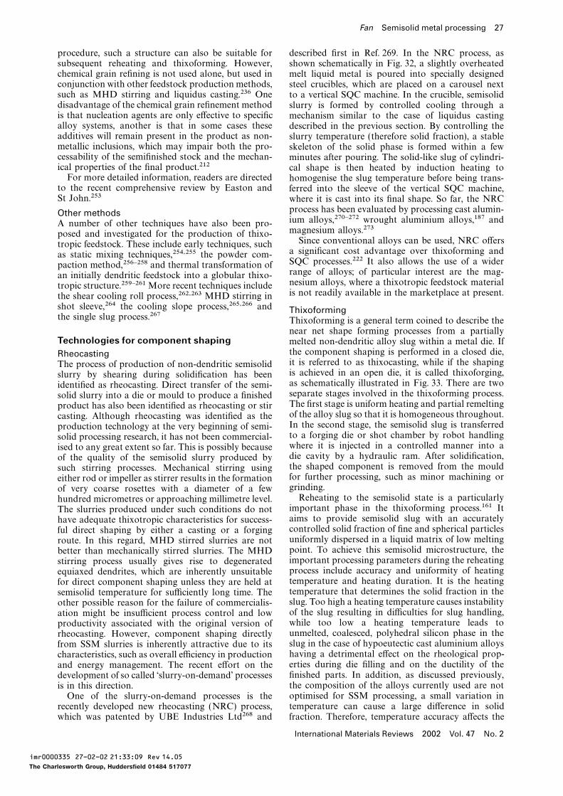
Fan Semisolid metal processing 27
procedure, such a structure can also be suitable for described first in Ref. 269. In the NRC process, assubsequent reheating and thixoforming. However, shown schematically in Fig. 32, a slightly overheatedchemical grain refining is not used alone, but used in melt liquid metal is poured into specially designedconjunction with other feedstock production methods, steel crucibles, which are placed on a carousel nextsuch as MHD stirring and liquidus casting.236 One to a vertical SQC machine. In the crucible, semisoliddisadvantage of the chemical grain refinement method slurry is formed by controlled cooling through ais that nucleation agents are only effective to specific mechanism similar to the case of liquidus castingalloy systems, another is that in some cases these described in the previous section. By controlling theadditives will remain present in the product as non- slurry temperature (therefore solid fraction), a stablemetallic inclusions, which may impair both the pro- skeleton of the solid phase is formed within a fewcessability of the semifinished stock and the mechan- minutes after pouring. The solid-like slug of cylindri-ical properties of the final product.212 cal shape is then heated by induction heating toFor more detailed information, readers are directed homogenise the slug temperature before being trans-
to the recent comprehensive review by Easton and ferred into the sleeve of the vertical SQC machine,St John.253 where it is cast into its final shape. So far, the NRC
process has been evaluated by processing cast alumin-Other methodsium alloys,270–272 wrought aluminium alloys,187 andA number of other techniques have also been pro-magnesium alloys.273posed and investigated for the production of thixo-Since conventional alloys can be used, NRC offerstropic feedstock. These include early techniques, sucha significant cost advantage over thixoforming andas static mixing techniques,254,255 the powder com-SQC processes.222 It also allows the use of a widerpaction method,256–258 and thermal transformation ofrange of alloys; of particular interest are the mag-an initially dendritic feedstock into a globular thixo-nesium alloys, where a thixotropic feedstock materialtropic structure.259–261More recent techniques includeis not readily available in the marketplace at present.the shear cooling roll process,262,263 MHD stirring in
shot sleeve,264 the cooling slope process,265,266 and Thixoformingthe single slug process.267 Thixoforming is a general term coined to describe the
near net shape forming processes from a partiallyTechnologies for component shaping melted non-dendritic alloy slug within a metal die. If
the component shaping is performed in a closed die,Rheocastingit is referred to as thixocasting, while if the shapingThe process of production of non-dendritic semisolidis achieved in an open die, it is called thixoforging,slurry by shearing during solidification has beenas schematically illustrated in Fig. 33. There are twoidentified as rheocasting. Direct transfer of the semi-separate stages involved in the thixoforming process.solid slurry into a die or mould to produce a finishedThe first stage is uniform heating and partial remeltingproduct has also been identified as rheocasting or stirof the alloy slug so that it is homogeneous throughout.casting. Although rheocasting was identified as theIn the second stage, the semisolid slug is transferredproduction technology at the very beginning of semi-to a forging die or shot chamber by robot handlingsolid processing research, it has not been commercial-where it is injected in a controlled manner into aised to any great extent so far. This is possibly becausedie cavity by a hydraulic ram. After solidification,of the quality of the semisolid slurry produced bythe shaped component is removed from the mouldsuch stirring processes. Mechanical stirring usingfor further processing, such as minor machining oreither rod or impeller as stirrer results in the formationgrinding.of very coarse rosettes with a diameter of a fewReheating to the semisolid state is a particularlyhundred micrometres or approaching millimetre level.important phase in the thixoforming process.161 ItThe slurries produced under such conditions do notaims to provide semisolid slug with an accuratelyhave adequate thixotropic characteristics for success-controlled solid fraction of fine and spherical particlesful direct shaping by either a casting or a forginguniformly dispersed in a liquid matrix of low meltingroute. In this regard, MHD stirred slurries are notpoint. To achieve this semisolid microstructure, thebetter than mechanically stirred slurries. The MHDimportant processing parameters during the reheatingstirring process usually gives rise to degeneratedprocess include accuracy and uniformity of heatingequiaxed dendrites, which are inherently unsuitabletemperature and heating duration. It is the heatingfor direct component shaping unless they are held attemperature that determines the solid fraction in thesemisolid temperature for sufficiently long time. Theslug. Too high a heating temperature causes instabilityother possible reason for the failure of commercialis-of the slug resulting in difficulties for slug handling,ation might be insufficient process control and lowwhile too low a heating temperature leads toproductivity associated with the original version ofunmelted, coalesced, polyhedral silicon phase in therheocasting. However, component shaping directlyslug in the case of hypoeutectic cast aluminium alloysfrom SSM slurries is inherently attractive due to itshaving a detrimental effect on the rheological prop-characteristics, such as overall efficiency in productionerties during die filling and on the ductility of theand energy management. The recent effort on thefinished parts. In addition, as discussed previously,development of so called ‘slurry-on-demand’ processesthe composition of the alloys currently used are notis in this direction.optimised for SSM processing, a small variation inOne of the slurry-on-demand processes is thetemperature can cause a large difference in solidrecently developed new rheocasting (NRC) process,
which was patented by UBE Industries Ltd268 and fraction. Therefore, temperature accuracy affects the
International Materials Reviews 2002 Vol. 47 No. 2
imr0000335 27-02-02 21:33:09 Rev 14.05
The Charlesworth Group, Huddersfield 01484 517077
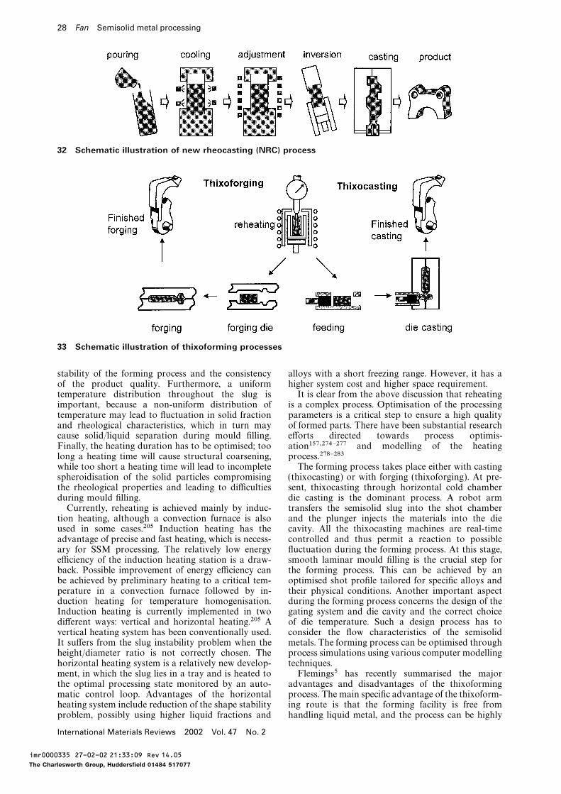
28 Fan Semisolid metal processing
32 Schematic illustration of new rheocasting (NRC) process
33 Schematic illustration of thixoforming processes
stability of the forming process and the consistency alloys with a short freezing range. However, it has ahigher system cost and higher space requirement.of the product quality. Furthermore, a uniform
temperature distribution throughout the slug is It is clear from the above discussion that reheatingis a complex process. Optimisation of the processingimportant, because a non-uniform distribution of
temperature may lead to fluctuation in solid fraction parameters is a critical step to ensure a high qualityof formed parts. There have been substantial researchand rheological characteristics, which in turn may
cause solid/liquid separation during mould filling. efforts directed towards process optimis-ation157,274–277 and modelling of the heatingFinally, the heating duration has to be optimised; too
long a heating time will cause structural coarsening, process.278–283The forming process takes place either with castingwhile too short a heating time will lead to incomplete
spheroidisation of the solid particles compromising (thixocasting) or with forging (thixoforging). At pre-sent, thixocasting through horizontal cold chamberthe rheological properties and leading to difficulties
during mould filling. die casting is the dominant process. A robot armtransfers the semisolid slug into the shot chamberCurrently, reheating is achieved mainly by induc-
tion heating, although a convection furnace is also and the plunger injects the materials into the diecavity. All the thixocasting machines are real-timeused in some cases.205 Induction heating has the
advantage of precise and fast heating, which is necess- controlled and thus permit a reaction to possiblefluctuation during the forming process. At this stage,ary for SSM processing. The relatively low energy
efficiency of the induction heating station is a draw- smooth laminar mould filling is the crucial step forthe forming process. This can be achieved by anback. Possible improvement of energy efficiency can
be achieved by preliminary heating to a critical tem- optimised shot profile tailored for specific alloys andtheir physical conditions. Another important aspectperature in a convection furnace followed by in-
duction heating for temperature homogenisation. during the forming process concerns the design of thegating system and die cavity and the correct choiceInduction heating is currently implemented in two
different ways: vertical and horizontal heating.205 A of die temperature. Such a design process has toconsider the flow characteristics of the semisolidvertical heating system has been conventionally used.
It suffers from the slug instability problem when the metals. The forming process can be optimised throughprocess simulations using various computer modellingheight/diameter ratio is not correctly chosen. The
horizontal heating system is a relatively new develop- techniques.Flemings5 has recently summarised the majorment, in which the slug lies in a tray and is heated to
the optimal processing state monitored by an auto- advantages and disadvantages of the thixoformingprocess. The main specific advantage of the thixoform-matic control loop. Advantages of the horizontal
heating system include reduction of the shape stability ing route is that the forming facility is free fromhandling liquid metal, and the process can be highlyproblem, possibly using higher liquid fractions and
International Materials Reviews 2002 Vol. 47 No. 2
imr0000335 27-02-02 21:33:09 Rev 14.05
The Charlesworth Group, Huddersfield 01484 517077
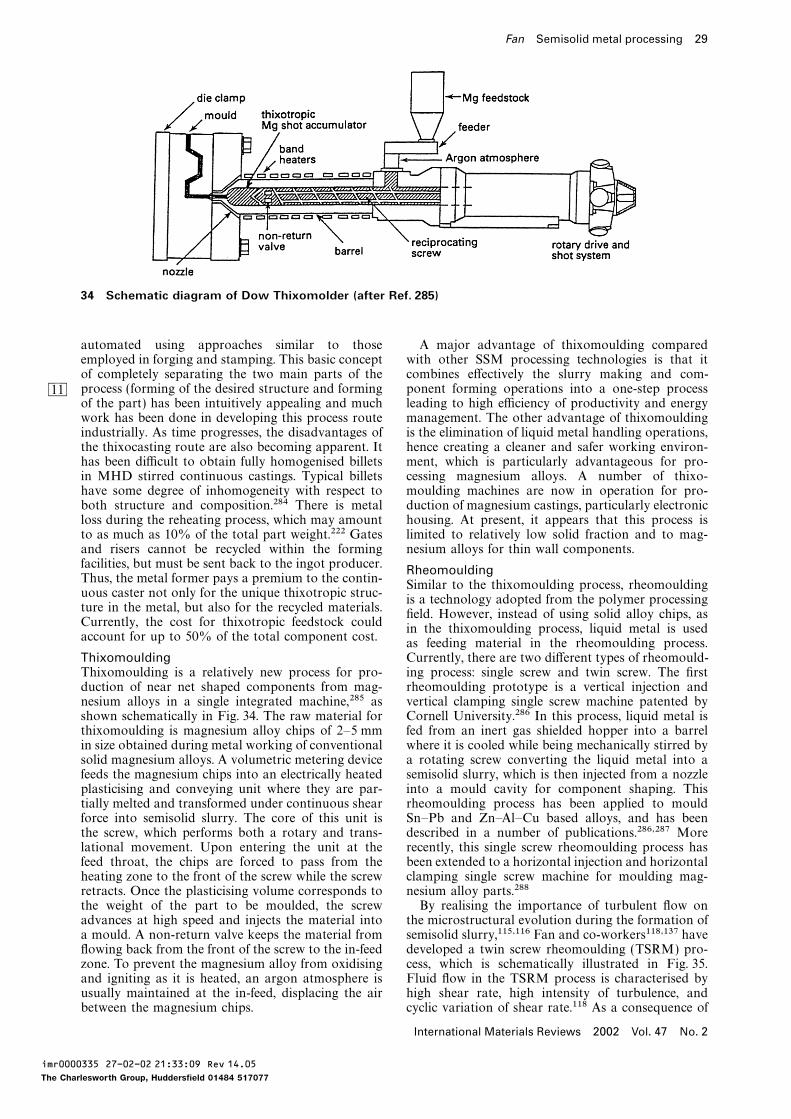
Fan Semisolid metal processing 29
34 Schematic diagram of Dow Thixomolder (after Ref. 285)
automated using approaches similar to those A major advantage of thixomoulding comparedwith other SSM processing technologies is that itemployed in forging and stamping. This basic concept
of completely separating the two main parts of the combines effectively the slurry making and com-ponent forming operations into a one-step processprocess (forming of the desired structure and formingBM
of the part) has been intuitively appealing and much leading to high efficiency of productivity and energymanagement. The other advantage of thixomouldingwork has been done in developing this process route
industrially. As time progresses, the disadvantages of is the elimination of liquid metal handling operations,hence creating a cleaner and safer working environ-the thixocasting route are also becoming apparent. It
has been difficult to obtain fully homogenised billets ment, which is particularly advantageous for pro-cessing magnesium alloys. A number of thixo-in MHD stirred continuous castings. Typical billets
have some degree of inhomogeneity with respect to moulding machines are now in operation for pro-duction of magnesium castings, particularly electronicboth structure and composition.284 There is metal
loss during the reheating process, which may amount housing. At present, it appears that this process islimited to relatively low solid fraction and to mag-to as much as 10% of the total part weight.222 Gates
and risers cannot be recycled within the forming nesium alloys for thin wall components.facilities, but must be sent back to the ingot producer. RheomouldingThus, the metal former pays a premium to the contin-
Similar to the thixomoulding process, rheomouldinguous caster not only for the unique thixotropic struc-
is a technology adopted from the polymer processingture in the metal, but also for the recycled materials.
field. However, instead of using solid alloy chips, asCurrently, the cost for thixotropic feedstock could
in the thixomoulding process, liquid metal is usedaccount for up to 50% of the total component cost.
as feeding material in the rheomoulding process.Currently, there are two different types of rheomould-Thixomoulding
Thixomoulding is a relatively new process for pro- ing process: single screw and twin screw. The firstrheomoulding prototype is a vertical injection andduction of near net shaped components from mag-
nesium alloys in a single integrated machine,285 as vertical clamping single screw machine patented byCornell University.286 In this process, liquid metal isshown schematically in Fig. 34. The raw material for
thixomoulding is magnesium alloy chips of 2–5 mm fed from an inert gas shielded hopper into a barrelwhere it is cooled while being mechanically stirred byin size obtained during metal working of conventional
solid magnesium alloys. A volumetric metering device a rotating screw converting the liquid metal into asemisolid slurry, which is then injected from a nozzlefeeds the magnesium chips into an electrically heated
plasticising and conveying unit where they are par- into a mould cavity for component shaping. Thisrheomoulding process has been applied to mouldtially melted and transformed under continuous shear
force into semisolid slurry. The core of this unit is Sn–Pb and Zn–Al–Cu based alloys, and has beendescribed in a number of publications.286,287 Morethe screw, which performs both a rotary and trans-
lational movement. Upon entering the unit at the recently, this single screw rheomoulding process hasbeen extended to a horizontal injection and horizontalfeed throat, the chips are forced to pass from the
heating zone to the front of the screw while the screw clamping single screw machine for moulding mag-nesium alloy parts.288retracts. Once the plasticising volume corresponds to
the weight of the part to be moulded, the screw By realising the importance of turbulent flow onthe microstructural evolution during the formation ofadvances at high speed and injects the material into
a mould. A non-return valve keeps the material from semisolid slurry,115,116 Fan and co-workers118,137 havedeveloped a twin screw rheomoulding (TSRM) pro-flowing back from the front of the screw to the in-feed
zone. To prevent the magnesium alloy from oxidising cess, which is schematically illustrated in Fig. 35.Fluid flow in the TSRM process is characterised byand igniting as it is heated, an argon atmosphere is
usually maintained at the in-feed, displacing the air high shear rate, high intensity of turbulence, andcyclic variation of shear rate.118 As a consequence ofbetween the magnesium chips.
International Materials Reviews 2002 Vol. 47 No. 2
imr0000335 27-02-02 21:33:09 Rev 14.05
The Charlesworth Group, Huddersfield 01484 517077
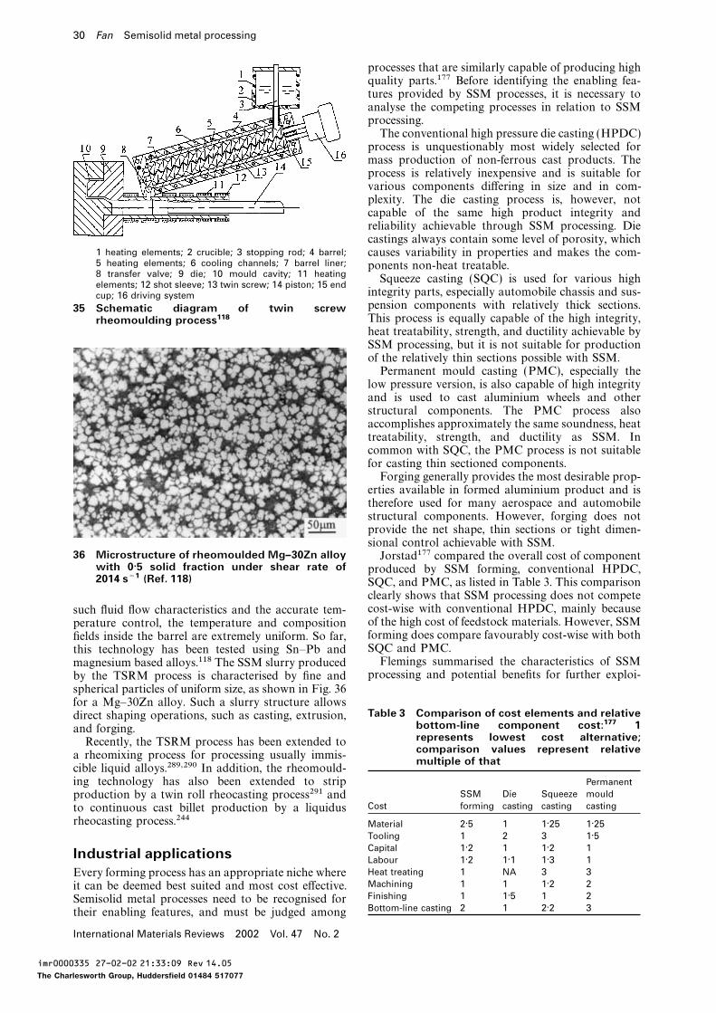
30 Fan Semisolid metal processing
processes that are similarly capable of producing highquality parts.177 Before identifying the enabling fea-tures provided by SSM processes, it is necessary toanalyse the competing processes in relation to SSMprocessing.The conventional high pressure die casting (HPDC)process is unquestionably most widely selected formass production of non-ferrous cast products. Theprocess is relatively inexpensive and is suitable forvarious components differing in size and in com-plexity. The die casting process is, however, notcapable of the same high product integrity andreliability achievable through SSM processing. Diecastings always contain some level of porosity, which
1 heating elements; 2 crucible; 3 stopping rod; 4 barrel; causes variability in properties and makes the com-5 heating elements; 6 cooling channels; 7 barrel liner; ponents non-heat treatable.8 transfer valve; 9 die; 10 mould cavity; 11 heating Squeeze casting (SQC) is used for various highelements; 12 shot sleeve; 13 twin screw; 14 piston; 15 end
integrity parts, especially automobile chassis and sus-cup; 16 driving systempension components with relatively thick sections.35 Schematic diagram of twin screwThis process is equally capable of the high integrity,rheomoulding process118heat treatability, strength, and ductility achievable bySSM processing, but it is not suitable for productionof the relatively thin sections possible with SSM.Permanent mould casting (PMC), especially thelow pressure version, is also capable of high integrityand is used to cast aluminium wheels and otherstructural components. The PMC process alsoaccomplishes approximately the same soundness, heattreatability, strength, and ductility as SSM. Incommon with SQC, the PMC process is not suitablefor casting thin sectioned components.Forging generally provides the most desirable prop-erties available in formed aluminium product and istherefore used for many aerospace and automobilestructural components. However, forging does notprovide the net shape, thin sections or tight dimen-sional control achievable with SSM.
36 Microstructure of rheomoulded Mg–30Zn alloy Jorstad177 compared the overall cost of componentwith 0·5 solid fraction under shear rate of produced by SSM forming, conventional HPDC,2014 s−1 (Ref. 118) SQC, and PMC, as listed in Table 3. This comparison
clearly shows that SSM processing does not competecost-wise with conventional HPDC, mainly becausesuch fluid flow characteristics and the accurate tem-of the high cost of feedstock materials. However, SSMperature control, the temperature and compositionforming does compare favourably cost-wise with bothfields inside the barrel are extremely uniform. So far,SQC and PMC.this technology has been tested using Sn–Pb andFlemings summarised the characteristics of SSMmagnesium based alloys.118 The SSM slurry producedprocessing and potential benefits for further exploi-by the TSRM process is characterised by fine and
spherical particles of uniform size, as shown in Fig. 36for a Mg–30Zn alloy. Such a slurry structure allows
Table 3 Comparison of cost elements and relativedirect shaping operations, such as casting, extrusion,bottom-line component cost:177 1and forging.represents lowest cost alternative;Recently, the TSRM process has been extended tocomparison values represent relative
a rheomixing process for processing usually immis- multiple of thatcible liquid alloys.289,290 In addition, the rheomould-
Permanenting technology has also been extended to stripSSM Die Squeeze mouldproduction by a twin roll rheocasting process291 and
Cost forming casting casting castingto continuous cast billet production by a liquidusrheocasting process.244 Material 2·5 1 1·25 1·25
Tooling 1 2 3 1·5Capital 1·2 1 1·2 1Industrial applications Labour 1·2 1·1 1·3 1Heat treating 1 NA 3 3Every forming process has an appropriate niche whereMachining 1 1 1·2 2it can be deemed best suited and most cost effective.Finishing 1 1·5 1 2Semisolid metal processes need to be recognised forBottom-line casting 2 1 2·2 3their enabling features, and must be judged among
International Materials Reviews 2002 Vol. 47 No. 2
imr0000335 27-02-02 21:33:09 Rev 14.05
The Charlesworth Group, Huddersfield 01484 517077
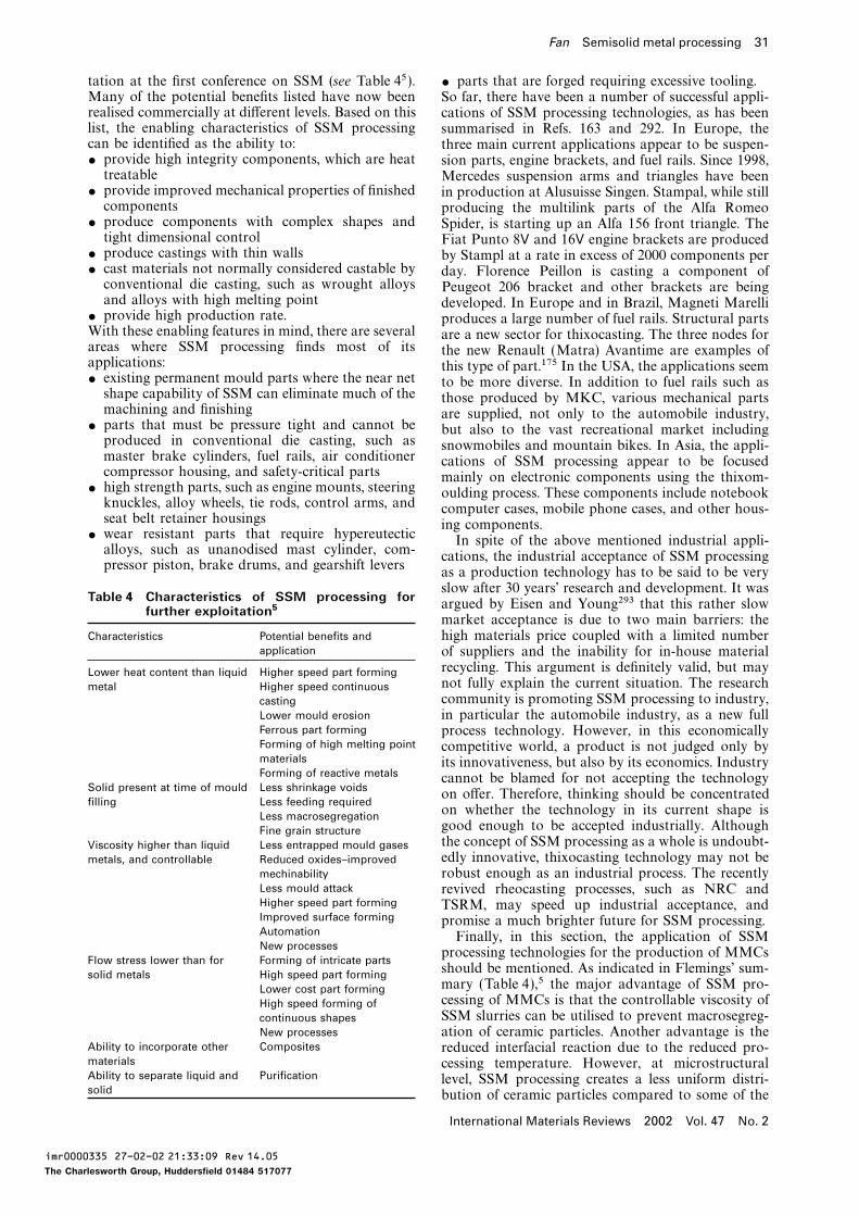
Fan Semisolid metal processing 31
tation at the first conference on SSM (see Table 45 ). $ parts that are forged requiring excessive tooling.Many of the potential benefits listed have now been So far, there have been a number of successful appli-realised commercially at different levels. Based on this cations of SSM processing technologies, as has beenlist, the enabling characteristics of SSM processing summarised in Refs. 163 and 292. In Europe, thecan be identified as the ability to: three main current applications appear to be suspen-$ provide high integrity components, which are heat sion parts, engine brackets, and fuel rails. Since 1998,treatable Mercedes suspension arms and triangles have been
$ provide improved mechanical properties of finished in production at Alusuisse Singen. Stampal, while stillcomponents producing the multilink parts of the Alfa Romeo
$ produce components with complex shapes and Spider, is starting up an Alfa 156 front triangle. Thetight dimensional control Fiat Punto 8V and 16V engine brackets are produced
$ produce castings with thin walls by Stampl at a rate in excess of 2000 components per$ cast materials not normally considered castable by day. Florence Peillon is casting a component ofconventional die casting, such as wrought alloys Peugeot 206 bracket and other brackets are beingand alloys with high melting point developed. In Europe and in Brazil, Magneti Marelli
$ provide high production rate. produces a large number of fuel rails. Structural partsWith these enabling features in mind, there are several are a new sector for thixocasting. The three nodes forareas where SSM processing finds most of its the new Renault (Matra) Avantime are examples ofapplications: this type of part.175 In the USA, the applications seem$ existing permanent mould parts where the near net to be more diverse. In addition to fuel rails such asshape capability of SSM can eliminate much of the those produced by MKC, various mechanical partsmachining and finishing are supplied, not only to the automobile industry,
$ parts that must be pressure tight and cannot be but also to the vast recreational market includingproduced in conventional die casting, such as snowmobiles and mountain bikes. In Asia, the appli-master brake cylinders, fuel rails, air conditioner cations of SSM processing appear to be focusedcompressor housing, and safety-critical parts mainly on electronic components using the thixom-
$ high strength parts, such as engine mounts, steering oulding process. These components include notebookknuckles, alloy wheels, tie rods, control arms, and computer cases, mobile phone cases, and other hous-seat belt retainer housings ing components.
$ wear resistant parts that require hypereutectic In spite of the above mentioned industrial appli-alloys, such as unanodised mast cylinder, com- cations, the industrial acceptance of SSM processingpressor piston, brake drums, and gearshift levers
as a production technology has to be said to be veryslow after 30 years’ research and development. It was
Table 4 Characteristics of SSM processing forargued by Eisen and Young293 that this rather slowfurther exploitation5market acceptance is due to two main barriers: the
Characteristics Potential benefits and high materials price coupled with a limited numberapplication of suppliers and the inability for in-house material
recycling. This argument is definitely valid, but mayLower heat content than liquid Higher speed part formingnot fully explain the current situation. The researchmetal Higher speed continuouscommunity is promoting SSM processing to industry,casting
Lower mould erosion in particular the automobile industry, as a new fullFerrous part forming process technology. However, in this economicallyForming of high melting point competitive world, a product is not judged only bymaterials its innovativeness, but also by its economics. IndustryForming of reactive metals cannot be blamed for not accepting the technology
Solid present at time of mould Less shrinkage voidson offer. Therefore, thinking should be concentrated
filling Less feeding requiredon whether the technology in its current shape isLess macrosegregationgood enough to be accepted industrially. AlthoughFine grain structurethe concept of SSM processing as a whole is undoubt-Viscosity higher than liquid Less entrapped mould gasesedly innovative, thixocasting technology may not bemetals, and controllable Reduced oxides–improved
mechinability robust enough as an industrial process. The recentlyLess mould attack revived rheocasting processes, such as NRC andHigher speed part forming TSRM, may speed up industrial acceptance, andImproved surface forming promise a much brighter future for SSM processing.Automation Finally, in this section, the application of SSMNew processes
processing technologies for the production of MMCsFlow stress lower than for Forming of intricate parts
should be mentioned. As indicated in Flemings’ sum-solid metals High speed part formingmary (Table 4),5 the major advantage of SSM pro-Lower cost part formingcessing of MMCs is that the controllable viscosity ofHigh speed forming ofSSM slurries can be utilised to prevent macrosegreg-continuous shapes
New processes ation of ceramic particles. Another advantage is theAbility to incorporate other Composites reduced interfacial reaction due to the reduced pro-materials cessing temperature. However, at microstructuralAbility to separate liquid and Purification level, SSM processing creates a less uniform distri-solid bution of ceramic particles compared to some of the
International Materials Reviews 2002 Vol. 47 No. 2
imr0000335 27-02-02 21:33:09 Rev 14.05
The Charlesworth Group, Huddersfield 01484 517077
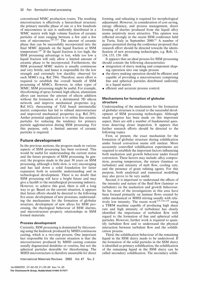
32 Fan Semisolid metal processing
conventional MMC production routes. The resulting forming, and reheating is required for morphologicaladjustment. However, in consideration of cost saving,microstructure is effectively a hierarchical structure:
the primary metallic phase of one or a few hundreds energy efficiency, and process management, directforming of slurries produced from the liquid alloyof micrometres in size is uniformly distributed in a
MMC matrix with high volume fraction of ceramic seems intuitively more attractive. This opinion wasreflected strongly in the recent SSM conference heldparticles of sizes ranging between a few and a few
tens of micrometres.147,217 The amount of ceramic in Turin, Italy in September 2000.11 A number ofpapers presented during the conference proposed thatphase that can be successfully incorporated into the
final MMC depends on the liquid fraction at SSM research effort should be directed towards the identi-fication of new processing technologies, e.g. Refs. 11,temperature.147 If the liquid fraction is too high, the
SSM processing advantage is lost, while too low a 154, 155, 158–160.It appears that an ideal process for SSM processingliquid fraction will only allow a limited amount of
ceramic phase to be incorporated. Furthermore, the should contain the following characteristics:$ integration of slurry making and component shap-SSM processed MMC matrix is usually continuous
and very brittle, and hence is responsible for the low ing operation into one single process$ the slurry making operation should be efficient andstrength and extremely low ductility observed for
such MMCs (e.g. Ref. 294). Therefore, more effort is capable of providing a microstructure comprisingfine and spherical particles distributed uniformlyrequired to establish the overall benefit of SSM
processing of MMCs. However, in other types of in a liquid matrix$ efficient and accurate process control.MMC, SSM processing might be useful. For example,
thixoforming of spray formed, high silicon, aluminiumalloys can increase the amount of silicon addition
Mechanisms for formation of globularwithout the formation of a detrimental 3D siliconstructurenetwork and improve mechanical properties (e.g.
Ref. 162); rheocasting of TiAl based intermetallic Understanding of the mechanisms for the formationof globular structure is crucial to the successful devel-matrix composites has led to refined microstructure
and improved mechanical properties (e.g. Ref. 295). opment of SSM processing technologies. Althoughmuch progress has been made on this importantAnther potential application is to utilise fine ceramic
particles for reducing the tendency for primary aspect, there are still a number of fundamental ques-tions deserving closer inspection. It appears thatparticle agglomeration during SSM processing. For
this purpose, only a limited amount of ceramic further research efforts should be directed to thefollowing topics.particles is required.First, at present, the exact mechanism for theformation of globular structure during solidificationFuture developmentunder forced convection seems still unclear. More
In the previous sections, the progress made in various accurately controlled solidification experiments areaspects of SSM processing has been reviewed. This required to establish the important factors influencingwould be useful for understanding the current status both nucleation and growth behaviour under forcedand the future prospects of SSM processing. In gen- convection. These factors may include: alloy compos-eral, the progress made in the past 30 years on SSM ition, pouring temperature, the nature ( laminar orprocessing, although a little slow, is very encouraging turbulent) and intensity of melt flow, cooling rate,and has laid down a solid foundation for faster and the presence of grain refining agents. For thisexpansion both in scientific understanding and in purpose, both analytical and numerical modellingtechnological development. There is no doubt that may also prove to be very useful.SSM processing will have a bright future and may Second, it is important to understand the effects ofgive a facelift to the metallurgical processing industry. the intensity and nature of the fluid flow (laminar orHowever, to achieve this goal, there is still a long turbulent) on the nucleation and growth behaviour.way to go. Based on the current situation, it appears So far, most of the investigations in this area havethat future efforts should be directed to the following been focused primarily on laminar flows created byfive areas: development of new processes, understand- either mechanical or MHD stirring usually with rela-ing the mechanisms for the formation of globular tively low intensity. The recent work115,116,119 usingstructure, development of new alloys for SSM pro- a TSRM machine capable of producing high shearcessing, the rheological behaviour of SSM slurries, rate and high intensity of turbulence has clearlyand microstructure–property relationships in SSM identified the importance of turbulent flow withformed materials. regard to the formation of fine and spherical solid
particles. However, further work is required to quan-Process development tify turbulent flow and to understand the physical
interaction between turbulent flow and the solidifi-Currently, SSM processing is dominated by thixocast-ing using the feedstock produced byMHD continuous cation process.
Third, the solidification behaviour of the remainingcasting, which is a two-step process. One importantfact responsible for the current situation is that the liquid in the SSM slurry needs to be understood. If
the formation of the solid particles in the SSM slurrymicrostructure produced by MHD casting containsusually degenerated dendrites or rosettes, but not the is identified as primary solidification, the solidification
of the remaining liquid in the SSM slurry can bespherical particles desirable for thixoforming. TheMHDmicrostructure is therefore unsuitable for direct called secondary solidification. The secondary solidi-
International Materials Reviews 2002 Vol. 47 No. 2
imr0000335 27-02-02 21:33:09 Rev 14.05
The Charlesworth Group, Huddersfield 01484 517077
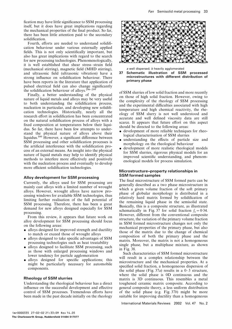
Fan Semisolid metal processing 33
fication may have little significance to SSM processingitself, but it does have great implications regardingthe mechanical properties of the final product. So far,there has been little attention paid to the secondarysolidification.Fourth, efforts are needed to understand solidifi-cation behaviour under various externally appliedfields. This is not only scientifically important, butalso has great implications with regard to the searchfor new processing technologies. Phenomenologically,it is well established that shear stress–strain field
a b
a well dispersed; b heavily agglomerated(mechanical stirring), magnetic field (MHD stirring),37 Schematic illustration of SSM processedand ultrasonic field (ultrasonic vibration) have a
microstructures with different distribution ofstrong influence on solidification behaviour. Thereprimary phasehave been reports in the literature that application of
pulsed electrical field can also change significantlythe solidification behaviour of alloys.296–299
of SSM slurries of low solid fraction and more recentlyFinally, a better understanding of the physical
on those of high solid fraction. However, owing tonature of liquid metals and alloys may be very useful
the complexity of the rheology of SSM processingto both understanding the solidification process,
and the experimental difficulties associated with highnucleation in particular, and developing new solidifi-
temperature and high chemical reactivity, the rhe-cation technologies. Historically, nearly all the
ology of SSM slurry is not well understood andresearch effort in solidification has been concentrated
accurate and well defined viscosity data are stillon the natural solidification process of alloys with a
scarce. It appears that future effort on this aspectfixed composition at temperatures below their liqui-
should be directed to the following areas:dus. So far, there have been few attempts to under-
$ development of more reliable techniques for rheo-stand the physical nature of alloys above their
logical characterisation of SSM slurriesliquidus.300 However, a significant difference between
$ understanding the effects of particle size andSSM processing and other solidification processes is
morphology on the rheological behaviourthe artificial interference with the solidification pro-
$ development of more realistic rheological modelscess of an external means. An insight into the physical
for SSM slurries, rigorous physical models for annature of liquid metals may help to identify physical
improved scientific understanding, and phenom-methods to interfere more effectively and positively
enological models for process simulation.with the nucleation process and eventually to developmore efficient solidification technologies.
Microstructure–property relationships inSSM formed samplesAlloy development for SSM processingThe final microstructure of SSM formed parts can be
Currently, the alloys used for SSM processing aregenerally described as a two phase microstructure in
mainly cast alloys with a limited number of wroughtwhich a given volume fraction of the soft primary
alloys. However, wrought alloys have narrow pro-phase of globular morphology is distributed in a
cessing windows for available SSM technologies, thusrelatively hard matrix formed by solidification of
limiting further realisation of the full potential ofthe remaining liquid phase in the semisolid state.
SSM processing. Therefore, there has been a greatBasically, this is a composite structure, as illustrated
demand for new alloys designed especially for SSMschematically in Fig. 37 for solid fraction fs=0·34.processing.However, different from the conventional composite
From this review, it appears that future work onstructure, the variation of the primary volume fraction
alloy development for SSM processing should focusin SSM formed microstructure changes not only the
on the following areas:mechanical properties of the primary phase, but also
$ alloys designed for improved strength and ductilitythose of the matrix due to the change of chemical
to match or exceed those of wrought alloyscomposition of both the primary phase and the
$ alloys designed to take specific advantages of SSMmatrix. Moreover, the matrix is not a homogeneous
processing technologies such as heat treatabilitysingle phase, but a multiphase mixture, as shown
$ alloys designed to facilitate SSM processing, suchin Fig. 38.
as those with enlarged processing windows andSuch characteristics of SSM formed microstructure
lower tendency for particle agglomerationwill result in a complex relationship between the
$ alloys designed for specific applications; thismicrostructure and the mechanical properties. At a
might be particularly necessary for automobilespecified solid fraction, a homogeneous dispersion of
components.the solid phase (Fig. 37a) results in a 0–3 structure,where the solid phase is 0D continuous and the
Rheology of SSM slurries matrix is 3D continuous. This resembles a metaltoughened ceramic matrix composite. According toUnderstanding the rheological behaviour has a direct
influence on the successful development and effective general composite theory, a less uniform distributionof the solid phase (e.g. Fig. 37b) might be morecontrol of SSM processes. Tremendous efforts have
been made in the past decade initially on the rheology suitable for improving ductility than a homogeneous
International Materials Reviews 2002 Vol. 47 No. 2
imr0000335 27-02-02 21:33:09 Rev 14.05
The Charlesworth Group, Huddersfield 01484 517077
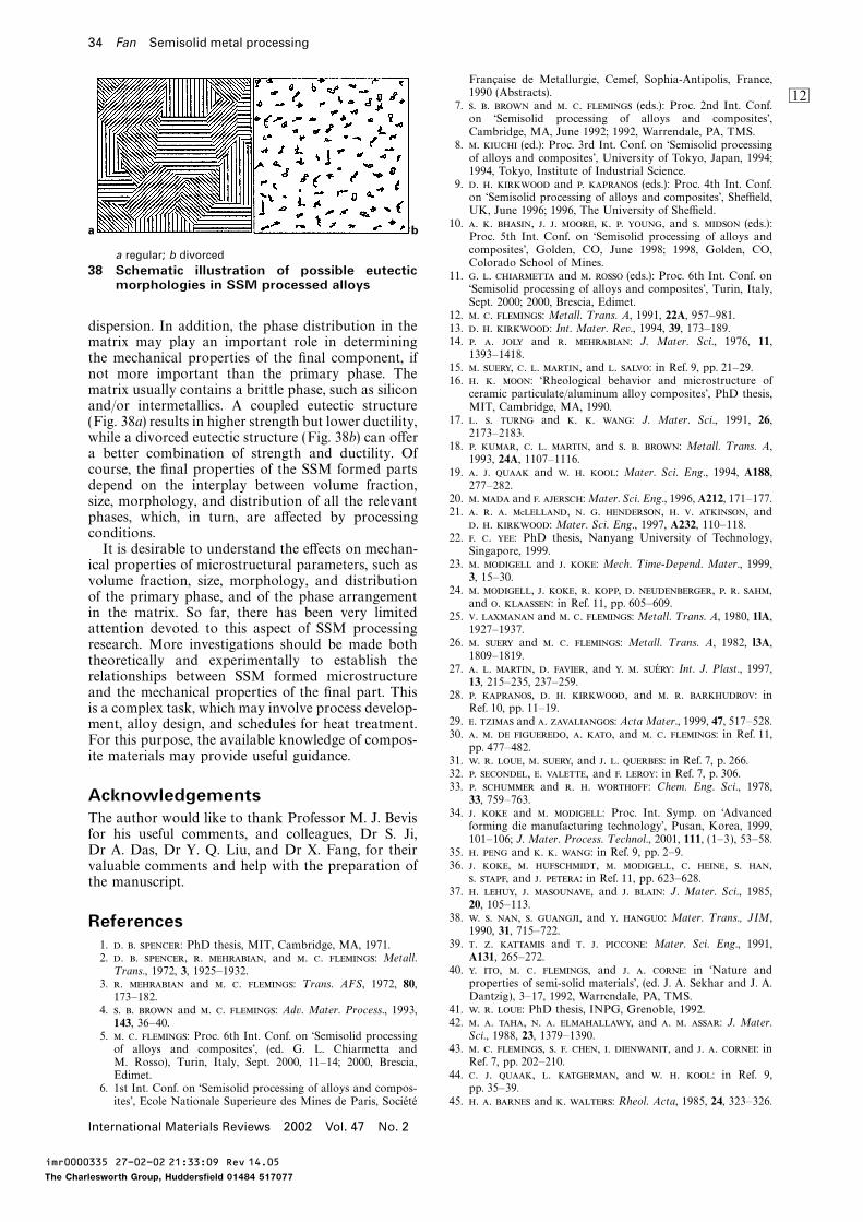
34 Fan Semisolid metal processing
Francaise de Metallurgie, Cemef, Sophia-Antipolis, France,1990 (Abstracts). BN
7. . . and . . (eds.): Proc. 2nd Int. Conf.on ‘Semisolid processing of alloys and composites’,Cambridge, MA, June 1992; 1992, Warrendale, PA, TMS.
8. . (ed.): Proc. 3rd Int. Conf. on ‘Semisolid processingof alloys and composites’, University of Tokyo, Japan, 1994;1994, Tokyo, Institute of Industrial Science.
9. . . and . (eds.): Proc. 4th Int. Conf.on ‘Semisolid processing of alloys and composites’, Sheffield,UK, June 1996; 1996, The University of Sheffield.
10. . . , . . , . . , and . (eds.):Proc. 5th Int. Conf. on ‘Semisolid processing of alloys and
a b
composites’, Golden, CO, June 1998; 1998, Golden, CO,a regular; b divorcedColorado School of Mines.
38 Schematic illustration of possible eutectic 11. . . and . (eds.): Proc. 6th Int. Conf. onmorphologies in SSM processed alloys ‘Semisolid processing of alloys and composites’, Turin, Italy,
Sept. 2000; 2000, Brescia, Edimet.12. . . : Metall. T rans. A, 1991, 22A, 957–981.
dispersion. In addition, the phase distribution in the 13. . . : Int. Mater. Rev., 1994, 39, 173–189.14. . . and . : J. Mater. Sci., 1976, 11,matrix may play an important role in determining1393–1418.the mechanical properties of the final component, if
15. . , . . , and . : in Ref. 9, pp. 21–29.not more important than the primary phase. The16. . . : ‘Rheological behavior and microstructure of
matrix usually contains a brittle phase, such as silicon ceramic particulate/aluminum alloy composites’, PhD thesis,and/or intermetallics. A coupled eutectic structure MIT, Cambridge, MA, 1990.
17. . . and . . : J. Mater. Sci., 1991, 26,(Fig. 38a) results in higher strength but lower ductility,2173–2183.while a divorced eutectic structure (Fig. 38b) can offer
18. . , . . , and . . : Metall. T rans. A,a better combination of strength and ductility. Of 1993, 24A, 1107–1116.course, the final properties of the SSM formed parts 19. . . and . . : Mater. Sci. Eng., 1994, A188,
277–282.depend on the interplay between volume fraction,20. . and . :Mater. Sci. Eng., 1996, A212, 171–177.size, morphology, and distribution of all the relevant21. . . . c, . . , . . , andphases, which, in turn, are affected by processing
. . : Mater. Sci. Eng., 1997, A232, 110–118.conditions. 22. . . : PhD thesis, Nanyang University of Technology,It is desirable to understand the effects on mechan- Singapore, 1999.
23. . and . : Mech. T ime-Depend. Mater., 1999,ical properties of microstructural parameters, such as3, 15–30.volume fraction, size, morphology, and distribution
24. . , . , . , . , . . ,of the primary phase, and of the phase arrangement
and . : in Ref. 11, pp. 605–609.in the matrix. So far, there has been very limited 25. . and . . :Metall. T rans. A, 1980, 1lA,attention devoted to this aspect of SSM processing 1927–1937.
26. . and . . : Metall. T rans. A, 1982, l3A,research. More investigations should be made both1809–1819.theoretically and experimentally to establish the
27. . . , . , and . . : Int. J. Plast., 1997,relationships between SSM formed microstructure 13, 215–235, 237–259.and the mechanical properties of the final part. This 28. . , . . , and . . : in
Ref. 10, pp. 11–19.is a complex task, which may involve process develop-29. . and . : Acta Mater., 1999, 47, 517–528.ment, alloy design, and schedules for heat treatment.30. . . , . , and . . : in Ref. 11,For this purpose, the available knowledge of compos-pp. 477–482.
ite materials may provide useful guidance. 31. . . , . , and . . : in Ref. 7, p. 266.32. . , . , and . : in Ref. 7, p. 306.33. . and . . : Chem. Eng. Sci., 1978,
Acknowledgements 33, 759–763.34. . and . : Proc. Int. Symp. on ‘AdvancedThe author would like to thank Professor M. J. Bevisforming die manufacturing technology’, Pusan, Korea, 1999,
for his useful comments, and colleagues, Dr S. Ji, 101–106; J. Mater. Process. T echnol., 2001, 111, (1–3), 53–58.Dr A. Das, Dr Y. Q. Liu, and Dr X. Fang, for their 35. . and . . : in Ref. 9, pp. 2–9.
36. . , . , . , . , . ,valuable comments and help with the preparation of. , and . : in Ref. 11, pp. 623–628.the manuscript.
37. . , . , and . : J. Mater. Sci., 1985,20, 105–113.
38. . . , . , and . : Mater. T rans., JIM,References1990, 31, 715–722.
39. . . and . . : Mater. Sci. Eng., 1991,1. . . : PhD thesis, MIT, Cambridge, MA, 1971.A131, 265–272.2. . . , . , and . . : Metall.
40. . , . . , and . . : in ‘Nature andT rans., 1972, 3, 1925–1932.properties of semi-solid materials’, (ed. J. A. Sekhar and J. A.3. . and . . : T rans. AFS, 1972, 80,Dantzig), 3–17, 1992, Warrcndale, PA, TMS.173–182.
41. . . : PhD thesis, INPG, Grenoble, 1992.4. . . and . . : Adv. Mater. Process., 1993,42. . . , . . , and . . : J. Mater.143, 36–40.Sci., 1988, 23, 1379–1390.5. . . : Proc. 6th Int. Conf. on ‘Semisolid processing
43. . . , . . , . , and . . : inof alloys and composites’, (ed. G. L. Chiarmetta andRef. 7, pp. 202–210.M. Rosso), Turin, Italy, Sept. 2000, 11–14; 2000, Brescia,
44. . . , . , and . . : in Ref. 9,Edimet.pp. 35–39.6. 1st Int. Conf. on ‘Semisolid processing of alloys and compos-
ites’, Ecole Nationale Superieure des Mines de Paris, Societe 45. . . and . : Rheol. Acta, 1985, 24, 323–326.
International Materials Reviews 2002 Vol. 47 No. 2
imr0000335 27-02-02 21:33:09 Rev 14.05
The Charlesworth Group, Huddersfield 01484 517077
Fan Semisolid metal processing 35
46. . . and . . . : J. Rheol., 1989, 33, 671–679. 94. . . , . , . , and . . : J. Appl. Phys., 1999, 86,2526–2532.47. . . : Can. Metall. Q., 1996, 35, 101–122.
95. . : Phys. Rev., 1983, 27A, 1495–1507.48. . , . , . , and . . : in96. . , . , . , . , . , andRef. 8, pp. 271–280.
. : in Ref. 11, pp. 423–428.49. . . , . , and . . : Acta Metall. Mater.,97. . : T rans. AIME, 1958, 212, 452.1994, 42, 3603–3614.98. . . and . : Mater. Sci. Eng., 1978, 33A, 125.50. . , . , and . : in Ref. 10, pp. 317–326.99. . . , . , and . . : in Ref. 11,51. . and . :Mater. Sci. Eng., 1996, A212, 157–170.pp. 367–372.52. . and . : in Ref. 11, pp. 129–135.
100. . , . . , . , and . . : in53. . . , . . , and . . : in Ref. 11,Ref. 11, pp. 121–127.pp. 161–167.
101. . , . , . , and . . : in54. . , . . , and . . : Acta Metall. Mater.,Ref. 8, pp. 75–84.1994, 42, 3595–3602.
102. . . , . . , and . . : Acta55. . , . . , . , . , and . : ActaMater., 1997, 45, 2279–2295.Mater., 2000, 48, 3773–3782.
103. . and . : in Ref. 10, pp. 637–644.56. . . and . : Mater. Sci. T echnol., 2002, 18, (3),104. . and . :Mater. Sci. Eng., 1999, A283, 70–75.237–242.105. . , . , and . : Mater. Sci. Eng., 1999,57. . and . . : Mater. Sci. T echnol., 2002, 18, (3),
A262, 300–303.243–249.106. . . : ‘Solidification processing’; 1974, New York,58. . . and . : Proc. ASTM, 1962, Vol. 26,
McGraw-Hill.pp. 621–633.107. . . , . . , . . , . ,59. . . : J. Non-Newton. Fluid Mech., 1999, 18, 133–178.
. , . , and . : Acta Mater., 2000,60. . . : J. Colloid. Sci., 1965, 20, 417–437.48, 43–70.61. . .-. : Int. J. Cosmetic Sci., 1987, 9, 151–191.
108. . . , . . , and . . : in Ref. 10,62. . . , . . , . , . . ,pp. 233–240.. . , and . . : in Ref. 11, pp. 545–551.
109. . , . . , and . : in ‘Solidification63. . and . : J. Mater. Eng. Perform., 1995,and casting of metals’, 518–525; 1979, London, The Metals4, 40–47.Society.64. . . , . . , . , and . : Mater.
110. . . and . . -: Proc. 46th Int. foundrySci. Eng., 1995, A202, 112–122.Congress, Madrid, Spain, 1979, paper 15.65. . , . , and . : Appl. Mech. Eng., 1999, BO
111. . , . . , and . . : Mater. Sci.4, 345–350.Eng., 1980, 46, 145–150.66. . . and . . : J. Rheol., 1999, 43,
112. . . van and . . : J. Mater. Sci., 1982,485–498.17, 989–993.67. . . and . : Mater. Sci. T echnol., 2002, 18, (3),
113. . . . , . . . . , and . :250–257.J. Mater. Sci., 1985, 20, 4335–4344.68. . , . , . , and . :
114. . . , . . , . , and . . : Metall.ISIJ Int., 1993, 33, 405–412.T rans. A, 1991, 22A, 575–584.69. . . , . . , and . : in Ref. 7, p. 266.
115. . and . : in Ref. 11, pp. 723–728.70. . . and . : Mater. Sci. Eng., 1995, A203, 1–13.116. . and . : Metall. Mater. T rans., submitted 2001. BP71. . . and . :Mater. Sci. T echnol., 2001, 17, 1149–1152.117. . . and . . : in Ref. 8, pp. 95–104.
72. . and . . : Mater. Sci. T echnol., 2002, 18, (3),118. . , . , and . . : Mater. Sci. Eng., 2001, A299,
258–267.210–217.
73. . . , . . , and . . : in119. . , . , and . : Mater. Sci. Eng. A, submitted 2001.
Ref. 11, pp. 681–686.120. . . and . : J. Mater. Sci., 1984, 19, 3995–4006.
74. . , . , and . :Metall. T rans. A, 2000,121. . . and . . . : Scr. Metall. Mater., 1994, 30,
31A, 57–62.1541–1546.
75. . , . , . , and . : in122. . . and . . . : J. Mater. Sci., 1995, 30, 4019–4026.
Ref. 9, pp. 10–15.123. . . , . . , and . . . : Scr. Mater., 1997, 37,
76. . , . , . , and . : in2003–2007.
Ref. 9, pp. 40–46.124. . and . : J. Mater. Sci., submitted 2001.
77. . . ’, . , and . : Int. J. Plast., 1994, 125. . : Metall. T rans. A, 1989, 20A, 247.10, 663–693. 126. . . and . . : Metall. T rans. A, 1975,
78. . . , . , and . : in Ref. 10, pp. 309–316. 6A, 197.79. . . , . . , and . : in Ref. 10, 127. . . , . . , and . . : T rans.pp. 217–224. AIME, 1967, 239, 1504.
80. . . and .-. : J. Fluids Mech., 1991, 222, 128. . and . . : Acta Metall. Mater., 1995,647–663. 43, 3207–3230.
81. .-. , . , . , . , . , 129. . and . : ‘Metastable effects obtained by solidificationand .-. : in Ref. 11, pp. 155–160. of eutectic Sn–Pb alloy under intensive forced convection’,
82. .-. : PhD thesis, INPG, Grenoble, France, 2000. Internal Report, Brunel University, Uxbridge, UK, 2002.83. . and .-. : T rans. Porous Media, 1999, 130. . and . : J. Cryst. Growth, 1977, 37, 309–316.36, 131–47. 131. . and . : J. Cryst. Growth, 1977, 41, 109–123.
84. . . : Metall. T rans. A, 1985, 16A, 1393–1403. 132. . : PhD thesis, University of Sussex, UK, 1977.85. . and . . : J. T heor. Appl. Mech., 1986, 133. . . and . . : J. Appl. Phys., 1963, 34, 323.5, 121–140. 134. . . , . . , and . . : Mater. Sci. Eng.,
86. . and . : J. Mech. Solids, 1993, 41, 1984, A65, 181–189.1087–1118. 135. . . , . . , . . , and . . : in
87. . : Int. J. Mech. Sci., 1999, 40, 1029–1041. ‘Solidification technology in the foundry and casthouse’, 119;88. . . : ‘Quantitative stereology’; 1972, Reading, 1983, London, The Metals Society.MA, Addisson-Wesley. 136. . : in Ref. 9, pp. 60–65.
89. . and . : J. Mater. Sci., 2000, 35, 137. . , . . , and . : ‘Method and apparatus for5319–5329. producing semisolid metal slurries and shaped components’,
90. . . : Rev. Mod. Phys., 1980, 52, 1–58. PCT/WO/01/21343 A1, 1999.91. . . , . . , and . . : Nature, 138. . . : Acta Mater., 1999, 47, 1783–1789.1984, 308, 721. 139. . . and . : in Ref. 11, pp. 819–824.
92. . . , . , . . , and . : Phys. 140. . , . , and . : Acta Mater., submitted 2001.Rev. L ett., 1992, 68, 213–216. 141. . , . , . and . . : Metall.
Mater. T rans., 1996, 17A, 2470–2478.93. . . and . . : J. Mater. Res., 1993, 8, 100.
International Materials Reviews 2002 Vol. 47 No. 2
imr0000335 27-02-02 21:33:09 Rev 14.05
The Charlesworth Group, Huddersfield 01484 517077
36 Fan Semisolid metal processing
142. . , . , and . : in Ref. 10, pp. 371–378. 188. . . : Proc. Phys. Soc. L ondon, 1951, 864B, 747.189. . . : J. Iron Steel Inst., 1953, 174, 25.143. . . and . . : J. Mater. Process. T echnol.,
2001, 109, 215–219. 190. . : Mater. Sci. Eng., 1995, A191, 73–83.191. . , . . , . . , and . : in144. . . and . . : J. Phys. Chem. Solids, 1961,
19, 35–50. Ref. 11, pp. 349–354.192. .-. , . . , and . : Proc. Int. Conf.145. . : Z. Elektrochem., 1961, 65, 581–591.
146. . , . , and . : in Ref. 9, pp. 187–192. on ‘Aluminium alloys: new processing technologies’, Ravenna,Italy, June 1993, 169–180; 1993, Milan, Associazione Italiana147. . . , . . , . . , . . , . . , and . .
: Mater. Sci. T echnol., 2000, 16, 887–892. di Metallurgia.193. . , . . -, and . . : Scr.148. . , . , . , and . : in
Ref. 10, pp. 693–698. Mater., 1995, 34, 483–489.194. . , . . -, and . . : in Ref. 9,149. . and . : Mater. Sci. Eng., 2000, A289,
217–227. pp. 326–330.195. . . and . . : in Ref. 11, pp. 337–342.150. . , . . , and . : Acta Metall., 1984,
32, 107–113. 196. . . : in Ref. 9, pp. 229–233.197. . and . : in Ref. 10, pp. 387–395.151. . and . . : in Ref. 7, pp. 328–335.
152. . . , . . , . , and . : in 198. . , . , and . : in Ref. 11, pp. 729–734.199. . . and . : ‘Magnesium and magnesium‘Modelling of casting and welding processes IV’; 1988,
Warrendale, PA, TMS. alloys’, 92; 1999, Materials Park, OH, ASM International.200. . . : in Ref. 8, pp. 65–74.153. . , . , . , and . : in Ref. 10,
pp. 353–360. 201. . . , . , . , . , and. : Proc. Int. Symp. on ‘Light metals processing and154. . , . , and . : in Ref. 11, pp. 483–488.
155. . . , . , and . . : in Ref. 11, applications’, Quebec City, PQ, Aug./Sept. 1993, 325; 1993,Montreal, PQ, CIM.pp. 443–450.
156. . . and . : ‘Critical assessment of thermal properties 202. . , . , . , . . , and . van :Proc. 34th Ann. Conf. of Metallurgists ‘Recent metallurgicalof Al-alloys’, Internal Report, Brunel University, Uxbridge,
UK, 2001. advances in light metals industries’, Vancouver, BC, Aug.1995, 481; 1995, Montreal, PQ, CIM.157. . , . , and . : in Ref. 9, pp. 159–164.
158. . : in Ref. 11, pp. 47–54. 203. . , . , . . , and . :Acta Mater., 2001, 49, 1225–1235.159. . : in Ref. 11, pp. 55–60.
160. . . : in Ref. 11, pp. 73–78. 204. . , . . , . . , and . . : inRef. 10, pp. 505–512.161. . , . , . , and . . : in Ref. 10,
pp. 199–213. 205. . . : in Ref. 10, pp. –.206. . . , . . , and . . : Mater. Sci. Eng.,162. . . , . . , . . . , . . ,
. , . , and . . -: Acta Mater., 1976, 25, 103–117.207. . , . . , and . . : in1996, 44, 1717–1727.
163. . , . , and h. : in Ref. 11, pp. 187–194. Ref. 10, pp. 57–67.208. . . and . . : Die Cast. Eng., Nov./Dec.164. . and . : in Ref. 11, pp. 301–306.
165. . : in Proc. International Magnesium Association Conf. : 1999, 70–78.209. . . , . . , . . , . . , . .IMA52, San Francisco, CA, May 1995, 1; 1995, McLean,
VA, IMA. , . . , and . . : in ‘Meta1s handbook’,9th edn, Vol. 15, 327–338; 1988, Metals Park, OH, ASM166. . . and . : Mater. Sci. Eng. A, submitted 2001.
167. . . , .-. , .-. , and . : in Ref. 11, International.210. . . , . , . , and . . :pp. 705–710.
168. . . , . . , . . , . . , and . : in in Ref. 7, pp. 33–46.211. . . , . , and . : Proc. Conf. on ‘DieRef. 10, pp. 141–148.
169. . , . , . , . , and . : casting technology’, Indianapolis, IN, 1995, 389; 1995,Rosemont, IL, North American Die Casting Association.in Ref. 10, pp. 465–470.
170. . , . . . , . . , . . , 212. . and . : in Ref. 9, pp. 180–186.213. . , . , and . . : in Ref. 9,. . , and . : in Ref. 10, pp. 379–385.
171. . . : in Ref. 9, pp. 204–207. pp. 154–158.214. . . and . : T rans. Iron Steel Inst. Jpn, 1988,172. . . , . , and . . :Mater. Sci. Eng., 2001,
A297, 69–77. 28, 97–103.215. . . , . . , and . . : ISIJ Int., 1995,173. . : in Ref. 9, pp. 239–241.
174. . and . : in Ref. 10, pp. 557–564. 35, 813–818.216. . : Metall. T rans. B, 1992, 23B, 189–206.175. . , . , and . . : in Ref. 11,
pp. 29–34. 217. . , . , . , and . :Mater. Sci. Eng.,1993, A173, 239–242.176. . . and . : in Ref. 11, pp. 97–102.
177. . . : in Ref. 11, pp. 227–233. 218. . , . , . . , and . : in Ref. 11,pp. 169–174.178. . . , . . , . , and . : in
Ref. 11, pp. 319–324. 219. . , . , . , and . : inRef. 10, pp. 407–414.179. . . , . . , . . , . , and
. : Mater. Sci. Eng., 1997, A237, 24–34. 220. . , . . , . . , and . : in ‘Lightmetals 1995’, (ed. J. W. Evans), 1233–1242; 1995, Warrendale,180. . . : ‘Aluminium and aluminium alloys’, 102–114, 533,
722–725; 1993, Materials Park, OH, ASM International. PA, TMS.221. European Patent Specification: EP 0 071 822 B2, Alumax181. . , . . , and -. : in Ref. 11,
pp. 581–586. Inc., 1982.222. . , . , and . : in Ref. 11, pp. 23–28.182. . , . , and . . : in Ref. 11,
pp. 209–214. 223. . . , . . , and . . : ‘Fine grainedmetal composition’, US Patent 4,415,374, 1983.183. . , . . , . . , . .
, . . , . . , . . , . , 224. . , . . , and . . : Proc. 2ndWorld Basque Cong. on ‘New structural materials’, Spain,. , . , . . -, . ,
. , and . . : in Ref. 11, pp. 741–745. 1988, Servico Central de Publicaciones del Gobierno Vasco,285–295.184. . . : ‘Aluminium and aluminium alloys’, 653–698; 1993,
Materials Park, OH, ASM International. 225. . . and . : Met. Mater., 1989, 5,(1), 16–19.185. . and . : in Ref. 10, pp. 473–480.
186. . : in Ref. 11, pp. 489–494. 226. . and . : in Ref. 9, pp. 71–74.227. . . , . . , . . , . . , and . . :187. . , . , and . . : in Ref. 11,
pp. 457–462. J. Korean Soc. Precis. Eng., 1996, 13, 29–35.
International Materials Reviews 2002 Vol. 47 No. 2
imr0000335 27-02-02 21:33:09 Rev 14.05
The Charlesworth Group, Huddersfield 01484 517077
Fan Semisolid metal processing 37
228. . . and . . : in Ref. 10, pp. 457–464. 264. . , . , . , and . : in Ref. 9,pp. 296–300.229. . . . , . -, and . : Mater.
265. . , . , . , . , and . : Proc.Sci. Eng., 1999, A272, 342–350.6th Int. Conf. on ‘Aluminium alloys’ (ICAA-6), 297–326; 1998,230. . , . -, . , and . : inJapan Institute of Light Metals.Ref. 10, pp. 3–10.
266. . and . : in Ref. 11, pp. 735–740.231. . . and . . : J. Mater. Process. T echnol., 1998,267. . -, . , and . . : in Ref. 9,82, 107–116.
pp. 174–179.232. . and . : Mater. Sci. Eng., 2000, A289,268. European Patent Specification, EP 0 745 694 A1, UBE228–240.
Industries Ltd.233. . . , . . , . . , and . :269. . : Proc. Japanese Die Casting Association, JD98–19,J. Mater. Syth. Proc., 1995, 3, 171.
Tokyo, 1998, 123–128.234. . and . : Mater. Sci. Eng., 1998, A246, 1–10.270. . , . , and . . : Aluminium,235. . : in Ref. 10, pp. –.
2000, 76, 70–75.236. . , . . , and . . t : in Ref. 11,271. . , . , and . . : Giesserei,pp. 149–154.
2000, 87, 39–43.237. . , . . t , . . , and . . :272. . , . , and . . : in Ref. 11,Aluminium T rans., 2000, 2, 57–66.
pp. 777–782.238. . , . . t , . . , and . . :
273. . , . , and . . : inMater. Sci. Forum, 2000, 329–330, 449–454.
Ref. 11, pp. 85–90.239. . , . , . , and . : in Ref. 11, pp. 701–704.
274. . and . : in Ref. 10, pp. 481–487.240. . . , . . , and . : J. Mater. Sci. L ett., 275. . and . : in Ref. 10, pp. 489–496.
1999, 18, 1869–1870. 276. . , . , and . : in Ref. 10, pp. 497–504.241. . : J. Australian Inst. Met., 1963, 8, 255. 277. . . and . . : Metall. Mater. T rans. A, 1999,242. . and . : J. Mater. Sci., 1968, 3, 139. 30A, 2967–2977.243. . . , . . , and . : T rans. 278. . , . , . , . , and
AIME, 1966, 236, 527. . : in Ref. 8, pp. 107–116.244. . , . , and . . : PCT/GB01/03596, 2000. 279. . . and . . : in Ref. 7, pp. 105–118.BQ245. . , . , and . : ‘Solidification structue of liquidus 280. . . : in Ref. 9, pp. 137–141.
rheocast Sn–Pb alloys’, Internal Report, Brunel University, 281. . , . . , . . , . . , andUxbridge, UK, 2001. . . : Mater. Sci. T echnol., 1996, 12, 274–278.
246. . . , . . , and . . : Vestnik Akad. 282. . , . . , . . , and . . :Nauk SSSR, 1984, 1, 139. in Ref. 9, pp. 148–152.
247. . . and . . : in Ref. 9, pp. 193–196. 283. . . , . . , and . . : J. Mater. Process.T echnol., 1999, 87, 46–52.248. . , . , and . : in Ref. 10, pp. 439–447.
284. . , . , and . : in Ref. 10,249. . . and . . : in Ref. 11, pp. 361–366.pp. 345–352.250. . . , . . , . . , and . :
285. . , . , . , and . : inMater. Des., 1997, 18, 323–326.Ref. 7, pp. 159–169.251. . , . , . , and . :Mater.
286. . , . . , . , and . . : in Ref. 8,L ett., 1998, 37, 27–34.pp. 191–200.252. . : ‘Ultrasound in liquid and solid metals’; 1994,
287. . , . , and . . : in Ref. 9, pp. 342–346.Boca Raton, FL, CRC Press.288. . and .-. : in Ref. 11, pp. 313–317.253. . and . t :Metall. Mater. T rans. A, 1999, 30A,289. . , . . , and . : ‘Process and apparatus for1613–1623, 1625–1633.
manufacturing castings from immiscible metallic liquids’,254. . . and . : Mater. Sci. T echnol., 1986, 4,PCT/WO 01/23124 A1, 1999.(2), 49–59.
290. . , . , and . : Mater. Sci. T echnol., 2001,255. . . and . : Foundry T rade J. Int., Dec.17, 837–842.
1987, 173–178.291. . , . , and . . : UK Patent Application
256. . . and . : in ‘Biomedical materials’, MRS0 019 855.6, 2000.
Symp. Proc. 55; 1986, Warrendale, PA, Materials Research292. . , . , . , and . : in Ref. 11,
Society. pp. 109–114.257. . . . and . . : Powder Metall., 1986, 293. . and . . : in Ref. 11, pp. 41–46.
29, 195–199. 294. . , . . , and . . : Mater. Sci. T echnol., 1997,258. . , . , . , . , and 13, 584–589.
. : in Ref. 9, pp. 165–168. 295. . and . : Mater. Sci. Eng., 1997, A240,259. French Patent Specification 7 506 954, Aluminium Pechiney, 493–502.
27 February 1975. 296. . . : Metall. T rans. A, 1985, 16A, 1254.260. ‘Process for manufacturing spheroidal hypoeutectic aluminum 297. . . : Metall. T rans. A, 1986, 17A, 358.
alloy’, US Patent Specification 5,009,844, General Motors 298. . . , . . , and . : Scr. Metall.Corp., 23 April 1991. Mater., 1995, 32, 879–884.
261. Patent Specification WO 96/32519, North West Aluminium, 299. . . and . . : Int. J. Non-Equilib. Process., 1998,17 October 1996. 11, 77–86.
262. . and . : in Ref. 7, pp. 47–56. 300. . and . . . : ‘The physics of liquid metals’;1988, Oxford, Clarendon Press.263. . and . : ISIJ Int., 1995, 35, 790–797.
International Materials Reviews 2002 Vol. 47 No. 2
imr0000335 27-02-02 21:33:09 Rev 14.05
The Charlesworth Group, Huddersfield 01484 517077

Authors Queries
Journal: International Materials Reviews
Paper: 335
Dear AuthorDuring the preparation of your manuscript, the queries listed below have arisen. The text to which thequeries pertain is indicated on the proof by a numbered box in the margin. Please answer the queries andreturn this form with your corrected proof. Many thanks for your co-operation.
Query RemarksQueryRefs
1 Author: Please check all equations throughout.
2 Author: OK, here, eta subscript 0 is the viscosityof the liquid matrix?
3 Author: OK s−1 for unit of shear rate – aselsewhere?
4 Author: OK the Fg in Fig. 11 is from equation20? However, now that refs. 69 and 70 have beenrenumbered, this use of Fg (ref 69 is 1992)appears to predate the statement ‘Loue andSuery70 introduced · · · ’ that appears aboveequation 20 in the text (ref. 70 is 1995).
5 Author: OK (equation (18)) added to Fig. 17caption with regard to F1?
6 Author: OK ‘In this paper’ or ‘In this section’?
7 Author: Does ‘both fragmentation and remeltingmechanisms’ here mean ‘neither thefragmentation nor the remelting mechanismoffers an explanation (i.e. the mechanismsconsidered separately), or ‘the fragmentation andremelting mechanisms combined do not offer’(i.e. the mechanisms acting in combination)?
8 Author: OK (equation (25)) added to Fig. 25caption with regard to this Fg?
9 Author: OK rewording of sentence ‘Theadvantage of such alloys fl 4Vx · · ’?
10 Author: OK rewording ‘. . . making it costapproximately 3–5 times more than the MHDstirring process.’
11 Author: OK ‘desired’?
12 Author: Ref. 6, 8, 211 month held (if possible)?
imr0000335 27-02-02 21:33:09 Rev 14.05
The Charlesworth Group, Huddersfield 01484 517077

Query RemarksQueryRefs
13 Author: Ref. 110 and 224: please do you haveany further details for these conferences, e.g.month held, organiser, and (if published) theyear of publication and name and location ofPublisher?
14 Author: Refs. 116, 119, 124,140, 166: just in case(since your e-mail ) do you have any updates onthe ‘Submitted’ refs yet please?
15 Author: Ref. 244, can you give the title for thisPCT ref ?
imr0000335 27-02-02 21:33:09 Rev 14.05
The Charlesworth Group, Huddersfield 01484 517077