sensitivity study of press quench process and concept of ... · control, and parts with distortion...
TRANSCRIPT

Sensitivity Study of Press Quench Process and Concept of Tooling Design for Reduced Distortion by ModelingZhichao (Charlie) Li and B. Lynn Ferguson
IntroductionQuench hardening is used to increase the hardness, strength, and fatigue perfor-mance of steel gears. A combination of carburizing and quenching can generate beneficial surface compressive residual stresses due to its delayed martensitic transformation in the case. The compres-sive residual stresses in the surface ben-efit the high cycle fatigue performance.
During quenching, stresses caused by the thermal gradient and phase trans-formations generate plastic deformation and distortion in hardened parts. Gear components with large distortion will increase gear noise and reduce the fatigue life in service. Final machining of case hardened gears often leads to nonuni-form case depth distribution, so a maxi-mum amount of distortion allowed by hardening is often specified for quality control, and parts with distortion exceed-ing the specification will be scrapped. Press quenching is one effective process to reduce distortion during hardening. Quench hardening is a transient ther-mal stress process; the main sources of distortion include the thermal stress and
phase transformation stress during both heating and cooling processes. The phase transformations make the quench hard-ening process highly nonlinear due to the changes of the thermal properties, mechanical properties and density of the material, and it is difficult to investigate the sources of distortion through experi-ments. Heat treatment results that are of common interest include the volume fractions of phases, hardness, residual stresses and part dimensional change. The development of heat treatment sim-ulation software makes it possible to understand the material response dur-ing the heat treatment process, includ-ing the evolution of internal stresses and deformation, the phase transformation sequences and the probability of crack-ing. Computer simulation has increased the level of understanding of heat treat-ment processes because the events that occur during heating and cooling can be accurately modeled. In turn, advances in computer hardware, in combination with accurate simulation, have made the design and optimization of heat treat-ment processes more cost effective than
traditional experimental trial-and-error methods. DANTE is a coupled ther-mal, carbon diffusion, phase transfor-mation and solid mechanics finite ele-ment based program for simulating the heat treatment of steel parts (Refs. 1, 2). DANTE material models link with either ABAQUS Standard or ANSYS Mechanical solvers. The modeling results include residual stress state after hardening, the evolution and final volume fractions of metallurgical phases, hardness, and part distortion. DANTE can be used to model austenitizing, gas carburizing, low pres-sure carburizing, immersion quench, high pressure gas quench, spray quench, induction hardening, press/plug quench, and tempering processes. In this paper, DANTE is used to investigate the sensi-tivities of several critical process param-eters on distortion for a press quenching process of a simplified thin-wall bevel gear.
Phase Transformation ModelsQuench hardening is a highly nonlin-ear process due to the phase transfor-mations, and the accuracy of the phase
Press quenching is designed to harden steel gears while minimizing distortion, and the process is especially applied for hardening large diameter thin-wall gears, face gears and bevel gears. The dimensional control aims at maintaining flatness, out-of-round, straightness and consistency of radial size. The press quench tooling and the process design have been mainly experience-based, using a trial and error approach for implementation of new processes, new gear materials and gear configurations. Both the out-of-round distortion and the radial distortion, including straightness and size change of thin-wall gears, are critical due to the maximum allowed grinding amount of the carburized case. Factors affecting the dimensional consistency of a press quench process can be classified as originating from gear/material conditions or the process parameters. The gear/material conditions include the variations of the initial gear dimensions, carbon distribution, residual stresses and material microstructures prior to hardening. The press quench process parameters include the heating rate, austenitizing temperature, applied load type, load amount, load location on the part from the tooling, friction between the tooling and the gear, and the quench rate, etc. All these factors may lead to inconsistent distortion, including the size and shape in quench-hardened parts. In this paper, the effects of several critical factors on dimensional inconsistency are analyzed using the heat treatment modeling software DANTE. The analysis results indicate that the current press quench with expander design does not effectively maintain a consistent radial size for thin-wall gears after hardening. By replacing the expander with an oversized plug, the effects of austenitizing temperature, cooling rate and initial gear size on the distortion are analyzed, and the press quench with plug design leads to consistent radial size. This concept of tooling design is demonstrated by modeling a hardening process for a simplified thin-wall spiral bevel gear made of carburized AISI 9310 steel.
Printed with permission of the copyright holder, the American Gear Manufacturers Association, 1001 N. Fairfax Street, Fifth Floor, Alexandria, VA 22314-1587. Statements presented in this paper are those of the author(s) and may not represent the position or opinion of the American Gear Manufacturers Association.
62 GEAR TECHNOLOGY | July 2018[www.geartechnology.com]
technical

transformation models is critical to the modeling results. The diffusive and martensitic transformation models in DANTE are described in Equations (1) and (2) below.
(1)dΦd = vd(T)Φdα1 (1–Φd)β1 Φadt
(2)dΦm = vm (1–Φm)α2 (Φm + φΦd)β2 ΦadT
Where Φd and Φm are the volume frac-tions of individual diffusive phase and martensite transformed from austenite; Φa is the volume fraction of austenite; νd and νm are the mobilities of tranforma-tion products, α1 and β1 are material related constants of diffusive transforma-tion; α2, β2, and ϕ are constants of mar-tensitic transformation. For each individ-ual phase formation, one set of transfor-mation kinetics parameters is required.
Dilatometry data are often used to characterize the martensitic phase trans-formation behavior of steels. Figure 1(a) is a continuous cooling dilatometry strain curve generated from the DANTE data-base, representing the martensitic forma-tion of AISI 9310. The horizontal axis in Figure 1(a) is temperature, and the vertical axis is the strain caused by tem-perature change and phase transforma-tion. The strain change due to martensitic transformation is clearly quantified by the dilatometry experiments.
When the dilatometry test sample cools below the martensitic transfor-mation start (Ms) temperature, its vol-ume expands with the crystal structure change from austenite’s face centered
cubic (FCC) lattice to martensite’s body centered tetragonal (BCT) lattice. Martensite’s BCT structure has a lower density than austenite’s FCC structure. The strain change during transforma-tion is a combination of thermal shrink-age and phase transformation expansion. The data obtained from this specific type of dilatometry test include coefficient of thermal expansion (CTE) for austenite and martensite, martensitic transforma-tion starting (Ms) and martensitic trans-formation finishing (Mf) temperatures, transformation strain, and phase trans-formation kinetics (transformation rate) from austenite to martensite. These data are critical to the accuracy of model-ing the internal stress and deformation caused by quenching.
Diffusive phase transformations are
also characterized by dilatometry tests. A series of dilatometry tests with different cooling rates can be used to fit a full set of diffusive and martensitic phase trans-formation kinetics parameters. Once the full set of phase transformation model parameters are fit from dilatometry tests, isothermal transformation (TTT) and continuous cooling transformation (CCT) diagrams can be generated for users to review. TTT/CCT diagrams are not directly used by DANTE phase trans-formation kinetics models, but they are useful because users can see the harden-ability of the material graphically. Figure 1(b) is an isothermal transformation dia-gram (TTT) for AISI 9310 steel created from the DANTE material database.
Figure 1 a) Dilatometry strain curve with martensitic transformation. b) TTT diagram of diffusive transformation for AISI 9310 steel.
Figure 2 Simplified thin-wall bevel gear. a) CAD model and dimensions. b) Finite element mesh.
63July 2018 | GEAR TECHNOLOGY

Figure 3 Modeling results of immersion oil quench process. a) Radial displacement. b) Axial displacement. c) Carbon fraction. d) Martensite fraction. e) Circumferential residual stress.
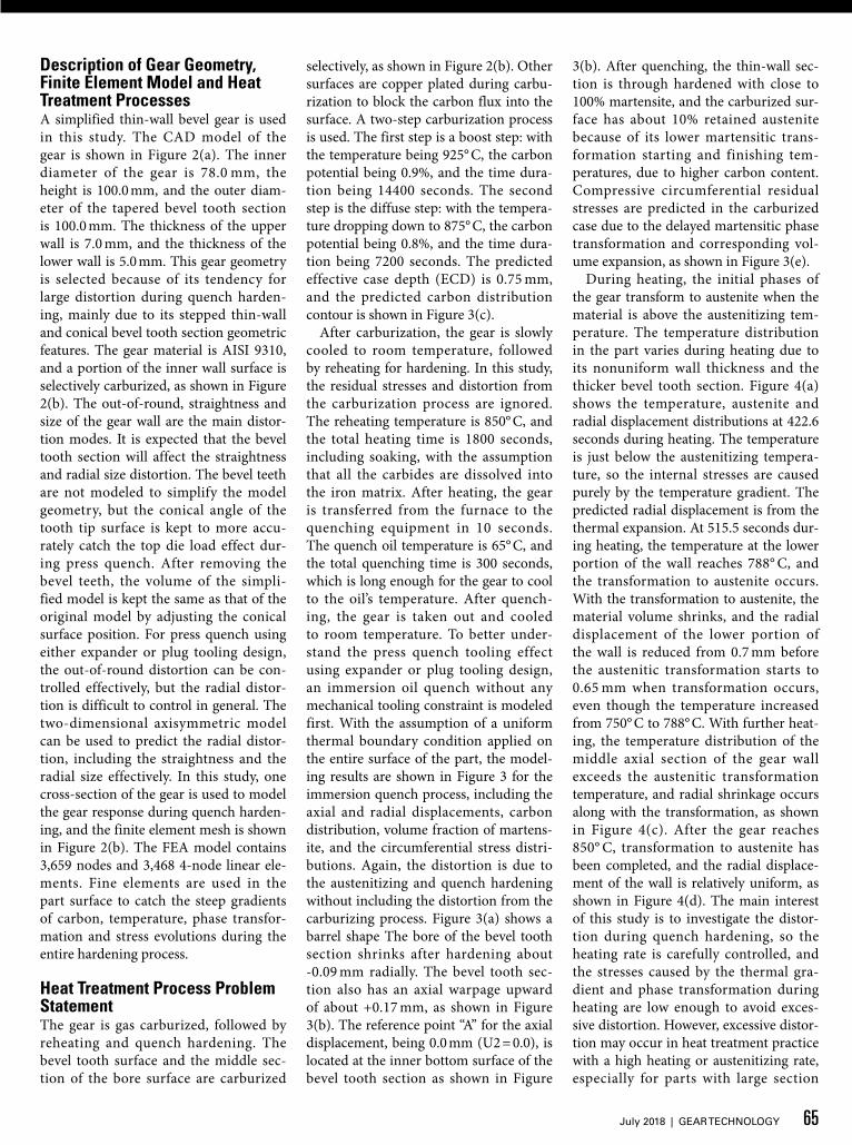
Figure 4 Temperature, austenite and radial displacement distribution contours during heating process. a) At 422.6 s. b) At 515.5 s. c) At 627.0 s. d) At the end of heating.
64 GEAR TECHNOLOGY | July 2018[www.geartechnology.com]
technical
Description of Gear Geometry, Finite Element Model and Heat Treatment ProcessesA simplified thin-wall bevel gear is used in this study. The CAD model of the gear is shown in Figure 2(a). The inner diameter of the gear is 78.0 mm, the height is 100.0 mm, and the outer diam-eter of the tapered bevel tooth section is 100.0 mm. The thickness of the upper wall is 7.0 mm, and the thickness of the lower wall is 5.0 mm. This gear geometry is selected because of its tendency for large distortion during quench harden-ing, mainly due to its stepped thin-wall and conical bevel tooth section geometric features. The gear material is AISI 9310, and a portion of the inner wall surface is selectively carburized, as shown in Figure 2(b). The out-of-round, straightness and size of the gear wall are the main distor-tion modes. It is expected that the bevel tooth section will affect the straightness and radial size distortion. The bevel teeth are not modeled to simplify the model geometry, but the conical angle of the tooth tip surface is kept to more accu-rately catch the top die load effect dur-ing press quench. After removing the bevel teeth, the volume of the simpli-fied model is kept the same as that of the original model by adjusting the conical surface position. For press quench using either expander or plug tooling design, the out-of-round distortion can be con-trolled effectively, but the radial distor-tion is difficult to control in general. The two-dimensional axisymmetric model can be used to predict the radial distor-tion, including the straightness and the radial size effectively. In this study, one cross-section of the gear is used to model the gear response during quench harden-ing, and the finite element mesh is shown in Figure 2(b). The FEA model contains 3,659 nodes and 3,468 4-node linear ele-ments. Fine elements are used in the part surface to catch the steep gradients of carbon, temperature, phase transfor-mation and stress evolutions during the entire hardening process.
Heat Treatment Process Problem StatementThe gear is gas carburized, followed by reheating and quench hardening. The bevel tooth surface and the middle sec-tion of the bore surface are carburized
selectively, as shown in Figure 2(b). Other surfaces are copper plated during carbu-rization to block the carbon flux into the surface. A two-step carburization process is used. The first step is a boost step: with the temperature being 925° C, the carbon potential being 0.9%, and the time dura-tion being 14400 seconds. The second step is the diffuse step: with the tempera-ture dropping down to 875° C, the carbon potential being 0.8%, and the time dura-tion being 7200 seconds. The predicted effective case depth (ECD) is 0.75 mm, and the predicted carbon distribution contour is shown in Figure 3(c).
After carburization, the gear is slowly cooled to room temperature, followed by reheating for hardening. In this study, the residual stresses and distortion from the carburization process are ignored. The reheating temperature is 850° C, and the total heating time is 1800 seconds, including soaking, with the assumption that all the carbides are dissolved into the iron matrix. After heating, the gear is transferred from the furnace to the quenching equipment in 10 seconds. The quench oil temperature is 65° C, and the total quenching time is 300 seconds, which is long enough for the gear to cool to the oil’s temperature. After quench-ing, the gear is taken out and cooled to room temperature. To better under-stand the press quench tooling effect using expander or plug tooling design, an immersion oil quench without any mechanical tooling constraint is modeled first. With the assumption of a uniform thermal boundary condition applied on the entire surface of the part, the model-ing results are shown in Figure 3 for the immersion quench process, including the axial and radial displacements, carbon distribution, volume fraction of martens-ite, and the circumferential stress distri-butions. Again, the distortion is due to the austenitizing and quench hardening without including the distortion from the carburizing process. Figure 3(a) shows a barrel shape The bore of the bevel tooth section shrinks after hardening about -0.09 mm radially. The bevel tooth sec-tion also has an axial warpage upward of about +0.17 mm, as shown in Figure 3(b). The reference point “A” for the axial displacement, being 0.0 mm (U2 = 0.0), is located at the inner bottom surface of the bevel tooth section as shown in Figure
3(b). After quenching, the thin-wall sec-tion is through hardened with close to 100% martensite, and the carburized sur-face has about 10% retained austenite because of its lower martensitic trans-formation starting and finishing tem-peratures, due to higher carbon content. Compressive circumferential residual stresses are predicted in the carburized case due to the delayed martensitic phase transformation and corresponding vol-ume expansion, as shown in Figure 3(e).
During heating, the initial phases of the gear transform to austenite when the material is above the austenitizing tem-perature. The temperature distribution in the part varies during heating due to its nonuniform wall thickness and the thicker bevel tooth section. Figure 4(a) shows the temperature, austenite and radial displacement distributions at 422.6 seconds during heating. The temperature is just below the austenitizing tempera-ture, so the internal stresses are caused purely by the temperature gradient. The predicted radial displacement is from the thermal expansion. At 515.5 seconds dur-ing heating, the temperature at the lower portion of the wall reaches 788° C, and the transformation to austenite occurs. With the transformation to austenite, the material volume shrinks, and the radial displacement of the lower portion of the wall is reduced from 0.7 mm before the austenitic transformation starts to 0.65 mm when transformation occurs, even though the temperature increased from 750° C to 788° C. With further heat-ing, the temperature distribution of the middle axial section of the gear wall exceeds the austenitic transformation temperature, and radial shrinkage occurs along with the transformation, as shown in Figure 4(c). After the gear reaches 850° C, transformation to austenite has been completed, and the radial displace-ment of the wall is relatively uniform, as shown in Figure 4(d). The main interest of this study is to investigate the distor-tion during quench hardening, so the heating rate is carefully controlled, and the stresses caused by the thermal gra-dient and phase transformation during heating are low enough to avoid exces-sive distortion. However, excessive distor-tion may occur in heat treatment practice with a high heating or austenitizing rate, especially for parts with large section
65July 2018 | GEAR TECHNOLOGY
thickness variations (Ref. 3). Stepped heating can be used to obtain more uni-form temperature in the part when phase transformation to austenite occurs, which is an effective method to control the dis-tortion caused by heating process.
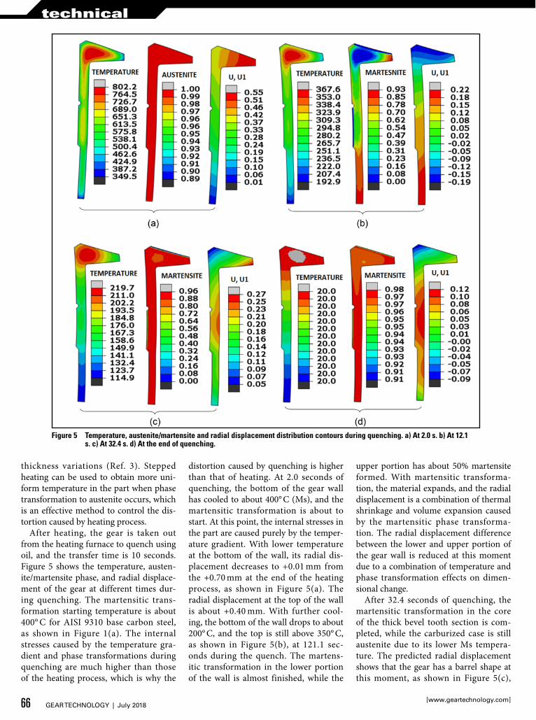
After heating, the gear is taken out from the heating furnace to quench using oil, and the transfer time is 10 seconds. Figure 5 shows the temperature, austen-ite/martensite phase, and radial displace-ment of the gear at different times dur-ing quenching. The martensitic trans-formation starting temperature is about 400° C for AISI 9310 base carbon steel, as shown in Figure 1(a). The internal stresses caused by the temperature gra-dient and phase transformations during quenching are much higher than those of the heating process, which is why the
distortion caused by quenching is higher than that of heating. At 2.0 seconds of quenching, the bottom of the gear wall has cooled to about 400° C (Ms), and the martensitic transformation is about to start. At this point, the internal stresses in the part are caused purely by the temper-ature gradient. With lower temperature at the bottom of the wall, its radial dis-placement decreases to +0.01 mm from the +0.70 mm at the end of the heating process, as shown in Figure 5(a). The radial displacement at the top of the wall is about +0.40 mm. With further cool-ing, the bottom of the wall drops to about 200° C, and the top is still above 350° C, as shown in Figure 5(b), at 121.1 sec-onds during the quench. The martens-itic transformation in the lower portion of the wall is almost finished, while the
upper portion has about 50% martensite formed. With martensitic transforma-tion, the material expands, and the radial displacement is a combination of thermal shrinkage and volume expansion caused by the martensitic phase transforma-tion. The radial displacement difference between the lower and upper portion of the gear wall is reduced at this moment due to a combination of temperature and phase transformation effects on dimen-sional change.
After 32.4 seconds of quenching, the martensitic transformation in the core of the thick bevel tooth section is com-pleted, while the carburized case is still austenite due to its lower Ms tempera-ture. The predicted radial displacement shows that the gear has a barrel shape at this moment, as shown in Figure 5(c),
Figure 5 Temperature, austenite/martensite and radial displacement distribution contours during quenching. a) At 2.0 s. b) At 12.1 s. c) At 32.4 s. d) At the end of quenching.
66 GEAR TECHNOLOGY | July 2018[www.geartechnology.com]
technical

and the positive values of the radial dis-placement mean the gear size is large than the original size. Between 32.4 sec-onds and the end of quenching, the car-burized case has further phase transfor-mation to martensite. The volume expan-sion caused by the martensitic phase transformation leads to compressive stresses in the case, which are balanced by tensile stresses in the core of the gear. Because the carburized case has a rela-tively small region, its delayed martens-itic transformation has an insignificant effect on further deformation of the part. The main contribution of deformation is from the thermal shrinkage of the part. At the end of quench, the middle sec-tion of the wall has a radial displacement of about +0.12 mm, the bottom is about 0.0 mm, and the top (bevel tooth section) is -0.09 mm. These results will be com-pared with press quench modeling results in later sections of this paper.
Press Quench using Expander/Plug Tooling DesignThe immersion oil quench modeling analysis shows that the sources of distor-tion can be summarized as the plastic deformation caused by the thermal stress and phase transformation stress. A 2D axisymmetric model is used to investigate the press quench process by assuming the gear behaves uniformly in the circum-ferential direction, so the out-of-round distortion is not modeled. In heat treat-ment practices, the oil flow around in the circumferential direction of the gear may not be uniform, which will cause out-of-round distortion. For gears with thin-wall feature, press quench is often used to reduce the distortion. For the simplified thin-wall bevel gear used in this study, an expander/plug is required to control the out-of-round distortion, straightness, and the radial size of the thin-wall section. Bottom and top dies are required to control the warpage of the bevel tooth section. Iterations of tool-ing designs are modeled using DANTE, with variations of tooling load applied. Four schematic tooling designs are shown in Figure 6. In each of the tool-ing designs, the expander/plug is mod-eled as two pieces, so the radial posi-tions of the lower and upper portion of the expander/plug can be more flexibly adjusted to control the straightness of
the gear. The expander/plug is short axi-ally in the tooling-1, tooling-2 and tool-ing-3 designs, as shown in Figures 6(a), 6(b) and 6(c). In the tooling-1 design, both the bottom and the top dies have small contact areas with the bevel tooth section. In the tooling-2 design, the size of the lower die is increased. In the tool-ing-3 design, both the bottom and top dies have increased contact area. In the tooling-4 design, the expander/plug size is increased to cover the entire bore of the gear wall. To model the press quench processes using either expander or plug, all the tool members are modeled as rigid surfaces. The bottom die is constrained, and the top die moves freely in the axial direction. A concentrated force is applied on the top die to control the axial warp-age of the bevel tooth section. In a press quench model using the expander, a con-centrated force is applied on the expander to control the radial distortion of the gear wall, and the expander can move in the radial direction. If the plug is used instead of the expander, the radial degree of freedom of the plug is constrained in the model. The radial position of the plug can be adjusted to represent different plug sizes. In later sections of this paper, a plug size of +0.0 mm means that the plug has a perfect contact with the gear wall at room temperature, while a plug size of +0.1 mm means the plug has a +0.1 mm overclosure radially with the bore of the gear at room temperature.
Using the press quench with the plug design, the effect of the four tool-ing designs shown in Figure 6 on the radial distortion of the gear wall and the
warpage of bevel tooth section is com-pared in Figure 7. A concentrated force of 10 KN is applied on the top die for all the four models. The plug size is +0.0 mm, which means the plug size is the same as the bore size of the gear at the room temperature. The predicted radial dis-placements (U1) of the four models have no significant difference. However, the predicted axial displacements (U2) of the bevel tooth section have noticible dif-ferences, indicating warping of the bevel tooth section. In tooling-1, tooling-2 and tooling-3 designs, the expander/plug doesn’t cover the entire bore surface of the gear, which makes both the radial and axial distortion of the bevel tooth section sensitive to the load applied on the top die. From modeling results with various plug size and die load combinations, it is found that the tooling-4 design produces the most consistent results in the four expander/plug tooling designs. In later sections of this paper, all the sensitivity studies of different process parameters are based on the tooling-4 design.
It is expected that the load applied on the top die doesn’t have significant effect on the radial distortion of the gear wall. Using the plug size +0.0 mm and the tool-ing-4 design, the effect of the top die load on the axial warpage of the bevel tooth section is investigated. Figure 8 shows the predicted axial displacements with 2.5 KN, 5.0 KN, 7.5 KN, 10.0 KN, and 12.5 KN loads on the top die. Without applying die load (immersion quench), the warpage of the bevel tooth is about +0.17 mm upward, as shown in Figure 3. By comparing the magnitude of axial
Figure 6 Press/Plug quenching tooling design. a) Tooling-1. b) Tooling-2. c) Tooling-3. d) Tooling-4.
67July 2018 | GEAR TECHNOLOGY

displacement predicted in Figure 8, a 10 KN die load is necessary to control the warpage of the bevel tooth section. The axial displace-ment predicted at the end of quenching includes the effects from both warpage and size change. A top die load that is too high will lead to low straightness of the gear wall because the top die pushes the bevel tooth section inward from the conical surface of the bevel tooth surface. After comparing the pre-dicted axial distortion, the 10 KN die load is selected for further pro-cess variable sensitivity investiga-tion in later sections of this paper.
In a press quench hardening process, either expander or plug designs can be used to control the radial displacement of thin-wall gear components. The radial dis-placements include the out-of-round distortion, straightness and the radial size of the hardened parts. In this study, the effect of plug size on the radial displacement is investigated, and the modeled plug sizes are +0.0 mm, +0.1 mm, +0.2 mm and +0.3 mm. Higher expander load or larger plug size will reduce the out-of-round dis-tortion in general. However, if the plug size is too large, it will be dif-ficult to insert the plug into the part due to possible out-of-round shape change and thermal shrinkage from the air transfer step. In this study, the largest plug size modeled is +0.3 mm. The predicted radial
Figure 7 Predicted radial and axial displacements from press quench model using the plug design with +0.0 mm plug size and 10 KN load applied on the top die. a) Tooling-1. b) Tooling-2. c) Tooling-3. d) Tooling-4.
Figure 8 Effect of top die load on predicted axial displacement using plug +0.0 mm and the tooling-4 design. a) 2.5 KN. b) 5.0 KN. c) 7.5 KN. d) 10.0 KN. e) 12.5 KN.
Figure 9 Effect of plug size on predicted radial displacements with the tooling-4 design and 10 KN applied on the top die. a) Plug size +0.0 mm. b) Plug size +0.1 mm. c) Plug size +0.2 mm. d) Plug size +0.3 mm.
68 GEAR TECHNOLOGY | July 2018[www.geartechnology.com]
technical

displacements are shown in Figure 9 for the several plug sizes. The load applied on the top die is 10 KN for all the models. With the plug size being +0.0 mm, the predicted minimum radial displacement is +0.101 mm at the bore of the bevel tooth section, and the maximum radial displacement is +0.23 mm at the middle height of the gear wall section. Compared to the radial displacements of -0.09 mm and +0.12 mm predicted for the immer-sion quench process as shown in Figure 3(a), the plug is effective in control-ling the radial size of the gear. However, the straightness of the gear wall is not improved using this plug. By increasing the plug size, the predicted radial dis-placement of the gear wall is getting more consistent, as shown in Figures 9(b), (c) and (d). Figure 4(d) shows that the radial displacement of the gear after heating is +0.69 mm, which will allow a maximum plug size of +0.69 mm. However, con-sidering a possible out-of-round shape change and thermal shrinkage during air transfer, a plug size of +0.3 mm is selected for further sensitivity analysis of other process parameters. The process consis-tency can be defined as the variation of process parameters that are found to be less sensitive to the obtained distortion in the hardened part. If the process is con-sistent, the initial gear configuration can be adjusted to compensate for distortion and size change. The goal of this study is to investigate the sensitivity of critical process parameters and how to improve the process consistency.
Sensitivity Analysis of Press Quench Hardening Process with Expander or Plug DesignThe critical process parameters in a press quench process include the austenitiz-ing temperature, the quenching rate and the applied loads, etc. In this modeling study, the effect of several critical pro-cess parameters on distortion is investi-gated. The difference between the press quench with expander and plug tooling designs is also analyzed. If the expander is used, the load applied on the expander is expected to affect the out-of-round, straightness, and size of the gear after hardening. Figure 10 shows the predicted radial displacement distribution contours from press quench with 2.5 KN, 5.0 KN, 7.5 KN, 10.0 KN, and 15.0 KN loads applied on the expander, respectively. The load doesn’t have a significant effect on the maximum radial displacement of the gear wall. However, its effect on the radial displacement of the bevel tooth section is significant. Higher expander load increases the radial displacement of the bevel tooth section, so the straight-ness of the gear wall is improved. The effect of the expander load on the radial displacement of the gear wall is highly nonlinear due to two main reasons: 1) different wall thickness leads to differ-ent thermal shrinkage between lower and upper portion of gear wall, and 2) martensitic transformation has a time difference between the lower and upper portion of the gear wall, which leads to material expansion at difference times.
The two factors will cause different inter-actions between the expander and the lower/upper portion of the gear wall. The different interactions include contact time and reaction force, which makes the radial shape of the gear wall nonlinear in terms of the load applied. From the mod-eling results, 10.0 KN is required to make the expander effect more consistent. In this paper, the 10 KN expander load will be used for the sensitivity analysis of other process parameters, including the austenitizing temperature and quenching rate, as well as gear initial size effect.
During the quench hardening process, the gear is first heated to transform to the austenite phase prior to quenching. The effect of austenitizing temperature on the radial distortion is shown in Figure 11, with the austenitizing temperature being 810° C, 825° C, 850° C, 875° C, and 900° C, respectively.
Lower austenitizing temperature is pre-ferred in press quench for more consis-tent results in general. However, the gear may not be fully austenitized if the aus-tenitizing temperature is too low, plus the temperature variation in the furnace. An austenitizing temperature of 810° C is often used in the industry for gears made of AISI 9310. With 810° C austenitizing temperature, the model assumes a com-plete transformation to austenite.
Using the same process setting with the plug +0.3 mm tooling design, the austen-itizing temperature effect on the radial displacement is shown in Figure 12. With the same legend range magnitude
Figure 10 Effect of expander load on predicted radial displacement using press quench with 850° C austenitizing temperature. a) 2.5 KN. b) 5.0 KN. c) 7.5 KN. d) 10.0 KN. e) 15.0 KN.
69July 2018 | GEAR TECHNOLOGY

Figure 11 Effect of austenitizing temperature on predicted radial displacement using press quench with a 10 KN load on top die and a 10 KN load on the expander. a) 810° C. b) 825° C. c) 850° C. d) 875° C. e) 900° C.
Figure 12 Effect of austenitizing temperature on predicted radial displacement using press quench with 10 KN load on top die and plug +0.3 mm design. a) 810° C. b) 825° C. c) 850° C. d) 875° C. e) 900° C.
Figure 13 Effect of quenching rate on predicted radial displacement using press quench with 850° C austenitizing temperature and 10 KN expander load. a) 50% HTC. b) 75% HTC. c) 100% HTC. d) 125% HTC. e) 150% HTC.
70 GEAR TECHNOLOGY | July 2018[www.geartechnology.com]
technical

(0.155 mm) used in Figures 11 and 12, the contour plot color can be used to compare the predicted radial displace-ments directly. With higher austenitiz-ing temperature, the predicted radial size of the bevel tooth section decreases, which is true for press quench using either expander or plug design. The pre-dicted straightness between the expander and the plug tool designs doesn’t show any significant difference by comparing Figures 11 and 12.
The cooling rate of the gear during quenching is affected by the oil tem-perature, oil flow pattern, oil flow rate, etc. Oil pumps are used in press quench equipment to drive the oil flow around the part, and the pumping power can be adjusted as a process parameter to affect the quenching rate. To investigate the effect of the quenching rate on dis-tortion, a series of heat transfer coeffi-cients are applied on the gear surface. The heat transfer coefficient is defined as a function of the part surface tem-perature (Ref. 4), and it is assumed that the entire surface has a uniform heat transfer coefficient applied with a con-stant oil temperature of 65° C for all the models. To evaluate the quenching rate effect, the heat transfer coefficient curve versus part surface temperature is multiplied by a factor. For example,
50% HTC means the values of the HTC is half of the values of the standard HTC. Figure 13 shows the predicted radial dis-placements from 50% HTC, 75% HTC, 100% HTC, 125% HTC and 150% HTC using the press quench with the expander tooling design. With faster cooling rate, the radial displacements decrease. With 50% HTC, the maximum radial displace-ment of the gear wall is about +0.14 mm, versus about +0.10 mm with 150% HTC (Figs. 13[a] and 13[e]).
With the same thermal boundary conditions and the plug +0.3 mm tool-ing design, Figure 14 shows the pre-dicted radial displacements. The pre-dicted radial displacement of the gear wall is more consistent compared to the results using the expander design, shown in Figure 13. The radial displace-ments of the bevel tooth section have a similar sensitivity level to the cooling rate between the expander and the plug +0.3 mm tooling designs.
The gear dimensions prior to quench-ing may vary due to the following pos-sible reasons: 1) dimensional difference due to previous machining processes, 2) residual stresses in the part prior to heat-ing and shape change due to the stress relaxation during heating, 3) distortion caused by carburizing and sequential cooling processes, and 4) distortion due
to reheating or austenitizing processes, etc. It is expected that the press quench process with either expander or plug design is effective for controlling the out-of-round distortion. However, controlling the radial size of the gear after harden-ing is critical if the part is carburized or selectively carburized, as only a small grinding amount after hardening should be permitted.
To make the post-processing of the final radial displacement contours more intuitive, the variation of the initial gear size is modeled by assigning the gear with specified initial temperatures, followed by ramping the gear to the room tem-perature of 20° C. The radial displace-ments, due to the thermal shrinkage or displacements of the bore to represent the gear sizes, the radial displacements are -0.10 mm, -0.05 mm, 0.0 mm, +0.05 mm, and +0.10 mm, as shown in the contour plots of Figure 15. Due to the thermal shrinkage or expansion, there are also initial radial displacements in the bevel tooth section, which will be carried over to the final predicted distortion after hardening. The internal stresses in the gear are zero prior to heating because the temperature in the gear is uniform during the temperature ramping process.
Figure 14 Effect of quenching rate on predicted radial displacement using the plug quench with 850° C austenitizing temperature and plug +0.3 mm tooling design. a) 50% HTC. b) 75% HTC. c) 100% HTC. d) 125% HTC. e) 150% HTC.
71July 2018 | GEAR TECHNOLOGY

Figure 16 Effect of initial gear size on predicted radial displacements using the press quench with 10 KN expander load and 850° C austenitizing temperature. a) –0.10 mm. b) –0.05 mm. c) 0.0 mm. d) +0.05 mm. e) +0.10 mm.
Figure 15 Radial displacement contours (initial gear sizes) of the gear at room temperature prior to heating. a) –0.1 mm. b) –0.05 mm. c) 0.0 mm. d) +0.05 mm. e) +0.1 mm.
Using the displacements shown in Figure 15 as the starting point, the press quench processes with both the expander and the plug tooling designs are mod-eled. The uniform standard heat trans-fer boundary conditions described pre-viously are applied for all the models, with the 10 KN load applied on the top die. Either the 10 KN will be applied on the expander, or the plug size +0.3 mm will be used for the two different tool-ing designs, respectively. The predicted radial displacements after hardening are shown in Figures 16 and 17 for various initial gear dimensions and the two tool-ing designs.
With a smaller gear dimension prior to heating, the final gear size is also smaller after hardening if the expander tooling design is used for the press quench pro-cess. As shown in Figure 16(a), the max-imum radial displacement of the gear wall predicted is about 0.0 mm if the ini-tial gear size is –0.10 mm. The predicted radial displacements are +0.057 mm, +0.112 mm, +0.170 mm, and +0.221 mm for the initial gear sizes of –0.05 mm, 0.0 mm, +0.05 mm, and +0.1 mm, respec-tively, as shown in Figures 16 (b) through (e). The predicted radial displacements after hardening in Figure 16 have sig-nificant difference. One conclusion is that
the final gear size is approximately lin-ear to the initial gear size prior to heat-ing. For gears with a radial size varia-tion before hardening, the final gear sizes after hardening will be scattered unless the press quench process can be adjusted accordingly, which may not be feasible in most cases.
Using the same process setting and replacing the expander by the plug +0.3 mm tooling design, the predicted radial displacements from various initial gear sizes are shown in Figure 17. The predicted radial displacements of the gear wall have a variation range of 0.03 mm (0.53 mm–0.50 mm). Compared to the
72 GEAR TECHNOLOGY | July 2018[www.geartechnology.com]
technical

results of 0.22 mm (0.22 mm–0.00 mm) from using the expander tooling design, the press quench with the oversized plug is much more consistent. The predicted straightness of the gear wall doesn’t have significant difference between the expander and the plug tooling designs. The straightness can be improved by using a profiled expander or plug configuration.
SummaryUsing a simplified bevel tooth gear with stepped thin-wall geometric features, the concept of press quench using either expander or plug tooling design is ana-lyzed by finite element models. The mod-eling results have clearly shown that the main sources of distortion are from the thermal stresses and phase transforma-tion stresses. With phase transformations, the material will be in plastic deforma-tion field due to the localized volume change of the material, which will make the gear shape change permanently even with low external load. Because of the phase transformations, the press quench can be effective with low load applied. During a press quench, the tooling inter-action with the gear includes the contact region, contact timing, and contact force. The modeling results have shown that the press quench with an oversized plug is much more consistent in controlling the distortion of hardened gear, compared to using the expander design. With more consistent distortion from the quench
hardening process, the initial gear con-figuration can be adjusted to compensate the distortion.
Bibliography1. B. L. Ferguson, A. Freborg, and G. Petrus,
“Software Simulates Quenching”, Advanced Materials and Processes, H31–H36, August (2000)
2. D. Bammann, et al., “Development of a Carburizing and Quenching Simulation Tool: A Material Model for Carburizing Steels Undergoing Phase Transformations”, Proceedings of the 2
nd
International Conference on Quenching and the Control of Distortion, 367–375, November (1996)
3. Z. Li, B. L. Ferguson, and A. Freborg, “Data Needs for Modeling Heat Treatment of Steel Parts”, Proceedings of Materials Science & Technology Conference, 219–226, (2004)
4. Ferguson, B.L., Freborg, A.M., Li, Z., “Probe Design to Charactrize Heat Transfer dur-ing Quenching Process”, Proceedings of 6th International Quenching and Control of Distortion Conference, Chicago, Illinois, September 9–13, 2012, pp. 792–801
Figure 17 Effect of initial gear size on the predicted radial displacements using the press quench with plug size +0.3 mm and 850° C austenitizing temperature. a) –0.10 mm. b) –0.05 mm. c) 0.0 mm. d) +0.05 mm. e) +0.10 mm.
Zhichao (Charlie) Li is the Vice President and one of the owners of DANTE Solutions, Inc., located in Cleveland, Ohio. Dr. Li’s area of expertise is design, innovation and optimization for heat treatment processes, materials characterization, and finite element modeling. Dr. Li’s responsibilities at DANTE are project management, heat treatment software development, new heat treatment process development, technical support, and new market development.
Dr. B. Lynn Ferguson, a graduate of Drexel University, is President of DANTE Solutions, Inc., formerly known as Deformation Control Technology, Inc., a company he founded in 1982. His career has focused on the broad field of mechanical metallurgy, with a concentration on thermal and mechanical processing of metals. Over the past twenty years, he has been primarily involved with analysis of the metallurgical events that take place during heat treatment of steel parts, including prediction of distortion, residual stress, and the evolution of microstructural phases. He has published more than 70 technical papers, authored many sections of various ASM handbooks, co-authored one book, and been an instructor in several sponsored short courses. He is a Fellow of
ASMI, Alpha Sigma Mu and IFHTSE.
73July 2018 | GEAR TECHNOLOGY
press quench
For Related Articles Search
at www.geartechnology.com