sentinel software manual - ringdale · pdf filesentinel installation and product authorization...
TRANSCRIPT

1
Sentinel Software ManualSoftware ManualSoftware ManualSoftware Manual
For the range of Ringdale Network I.D. Readers

2
Version 5.2 March 2007
COPYRIGHT
Copyright 2004 © Ringdale UK Ltd. All rights reserved. No part of this
publication may be reproduced, transmitted, transcribed, stored in a retrieval
system, or translated into any language or any computer language, in any form or by any third party, without prior permission of Ringdale UK Limited.
DISCLAIMER
Ringdale UK Ltd. reserves the right to revise this publication and to make
changes from time to time to the contents hereof without obligation to notify
any person or organization of such revision or changes. Ringdale UK Ltd. has
endeavored to ensure that the information in this publication is correct, but will
not accept liability for any error or omission.
Because of the fast pace of software development it is possible that there will
be differences between the manual and the program.
TRADEMARKS
All trademarks are hereby acknowledged.

3
Contents
Contents............................................................................................................................................. 3
Introduction ........................................................................................................................................ 4 System Requirements ........................................................................................................................... 4
Configuring an ID Reader/Access Controller to the Network ......................................................................... 5 Additional Options.............................................................................................................................. 8 Deleting an ID Reader/Access Controller From Sentinel ............................................................................ 9
Access and Security Settings ................................................................................................................ 10 A. Access Times ......................................................................................................................... 11 B. Calendar .................................................................................................................................... 12
Setting Up Users for the ID Reader........................................................................................................ 14 Stopping the Sentinel Service ............................................................................................................ 14 Changing the Server Port .................................................................................................................. 15 ID Card.......................................................................................................................................... 18 Keypad PIN (Personal Identification Number) ....................................................................................... 19 Fingerprint Registration .................................................................................................................... 20 Restarting the Sentinel Service .......................................................................................................... 23 Changing Back the Server Port for the Controller................................................................................... 24
Assigning Users to a Group .................................................................................................................. 25 and Managing Users for more than One ID Reader ................................................................................... 25 Changing Group Configurations .......................................................................................................... 28 Deleting Groups .............................................................................................................................. 28
Door Strike and Bolt Control Options ..................................................................................................... 29 Quick Select Options ........................................................................................................................ 34
Uploading Settings to the ID Reader/Access Controller.............................................................................. 35 a) Quick Upload Method to Single ID Reader/Access Controller............................................................ 35 b) Multiple Upload Method Using the Upload Wizard............................................................................... 35
Time and Attendance Terminal ............................................................................................................. 39
Retrieving Information from the ID Reader/Access Controller..................................................................... 41 Serial / USB Devices ........................................................................................................................... 43
Remote Administration ........................................................................................................................ 47 Example Report............................................................................................................................... 50
Sentinel Installation and Product Authorization ........................................................................................ 52 Installation ..................................................................................................................................... 52 Product Authorization ....................................................................................................................... 53
First Time Set-Up Procedure................................................................................................................. 56 Microsoft Access .............................................................................................................................. 57 SQL Server..................................................................................................................................... 58
Daylight Saving Time Setting Adjustments.............................................................................................. 60
Uninstalling the Sentinel Software ......................................................................................................... 61 Questions and Answers ....................................................................................................................... 62
Index ............................................................................................................................................... 63

4
Introduction
Sentinel is Ringdale’s management software for use with their access control systems and Network I.D. Readers. Sentinel can be installed on any Windows 98/NT4/2000/XP PC connected to an Ethernet Local or Wide Area
Network (LAN or WAN).
It provides full configuration, management and monitoring capability for applications such as door strikes, bolts,
and time & attendance systems across the network from the administrators PC.
Issue each employee with an ID card or pin number that has a unique built-in code that can identify him or her.
Alternatively scan the employees’ fingerprint(s) into the database if fingerprint readers are to be utilized or
required. Once the user has been identified they can be granted access through a door, clocked in etc. depending
on the application for which the ID reader is being used.
The Sentinel software is used to configure the ID reader or access controller to the network and to set up users.
Sentinel allows comprehensive access and security settings to be configured for each user, and the creation of log and database files for generating reports of usage. Sentinel can manage multiple readers/controllers on the
network.
The Duplo and Solo ID reader/controllers download data to the Sentinel Server once every minute, ensuring that
the software always has an up-to-date record. Combi Readers are real time.
Setting up the ID reader/access controller involves two main procedures:
1 Installing the ID reader/access controller in suitable locations.
2 Installing and configuring the software onto the designated server.
This guide provides installation, configuration and user instructions for the Sentinel software and should be used in
conjunction with the ID reader or access controller Quick Installation Guide also supplied.
The installation and first-time setup procedures are at the end of the manual.
You can run multiple copies of the Sentinel.NET software. One installation should be used to run the system, and the other to make changes. Each of the readers (combi, proximity, Duplo, or solo) can be pointed to any Sentinel
Server, but it must be running. Typically you will have them all pointed to the same Sentinel Server that will
always be kept running, while using other copies of the Sentinel.NET software to make changes.
The database (SQL or Access) that you use will usually be on the same SERVER that the readers point to as the
main Sentinel Server, but this is not an absolute requirement.
System Requirements
You must first install Microsoft. NET. See the Microsoft website for system requirements.
Sentinel.NET Server Platform: Windows 98/ME/NT/2000/2003/XP Professional.
10MB RAM
10MB disk space

5
Configuring an ID Reader/Access Controller to the Network
To configure an ID reader/access controller to the network use the following procedure:
Open the Sentinel program and from the main window
1 Open the Sentinel program and from the main window click on the Network Devices icon, as shown here:
The following window will be displayed (NOTE: this will be empty when opened for the first time):
2 After ensuring that the ID reader/controller has been installed on the network, click the _Requery Network_
button. All ID readers/controllers on the network will be listed in the window. Sentinel will display the details of the device to be configured with a factory default IP address of:
11.22.33.44
IMPORTANT: If installing more than one ID reader/access controller it is advised that each is configured
immediately after installation before the next is installed onto the network. There will be difficulties in identifying
which device is which if more than one unconfigured device is on the network sharing the same factory default IP address.

6
Locating ID Readers/Access Controllers on Different Networks/Subnets
If the ID reader/access controller is on a different network/subnet to the SERVER with the Sentinel software the
program will not instantly identify it. Click on the Network Restrictions button to display the following dialog
box:
1 Click on the Add button to display this dialog box:
Use the subnet address or the IP Address of the device (xxx.xxx.xxx.255 will find all devices on the network
without having to enter a specific IP address) and click the OK button. The address will appear on the list in
the Network Restrictions dialog box. Ensure that the address is selected before clicking the OK button again.
2 Click the button to list the device in the Network Devices window.
Requery Network uses UDP to find all devices on the network. If the network is busy, it may not find all of the
devices. To ensure that it finds a device, add it to the Network Restrictions list.
3 Double-click or highlight the device on the list and click the Properties button to display the General page
for that device. Sentinel queries the device and displays the Device Properties for that specific device. The options that you see for Type are dependent on the actual hardware and code version installed in that hardware, for
example Input Channels, Locks, and Physical Lock Types tabs may not be present. You may or may not see the
Combi Type field depending on the hardware.

7
4 Use this page to configure the ID reader/controller to the network by providing the Device Name (this should be something that will easily allow the specific device to be identified), IP Address and Subnet Mask.
5 If the Sentinel Server and the device are on different networks, it will be necessary to enter the Default Gateway IP Address.
6 The Auto IP check box determines whether to allow the IP address of the device to be set using Ping or ARP and thus be seen by Sentinel. This is not a DHCP enable. The current Combi-readers require that this be ticked.
The earlier Solo and Duplo hardware required that it be unchecked. This feature is currently ticked by
default.
7 In the Server IP Address box, enter the IP address of the Sentinel Server. The Sentinel Server will be the
server that always has the Sentinel.NET software running.
For details on the Server Port box see the section Setting Up Users for the ID Reader – this doesn’t need to be
attended to at this time.
8 From the Type drop-down box under the General tab, select the type of ID reader that is connected to the
device.
If you have an older Solo or Duplo reader, there will be the option to choose whether the device operates
using the data on the unit itself, or through direct ‘real time’ communication with the Sentinel Server. If a
fingerprint reader is being used, the Data On Server option must be selected (the amount of data stored for fingerprints is too large to be stored on the device). If the Data On Unit option is selected, all new data must be
uploaded to the device after being entered into Sentinel (see the section Uploading Settings to the ID
Reader/Access Controller for full details of this). With the Data On Server option selected, the device will communicate with Sentinel for every action, thus will always have access to the latest data. With the Data On Unit
option selected, the device may operate faster and will also continue to operate if the network is down.
NOTE: There may also be a Combi Type drop-down box present. Select the type of combi reader that is being
used.
9 Because of the sensitive nature of the information that is configured with this software, access to change any of
the settings can be restricted by setting a password.

8
Click the Password button and enter a password into the New Password box. Enter the confirmation password
and click on the OK button.
NOTE: It is recommended that all devices be set with the same password - while different passwords for different
devices can be used with manual retrieval of logs, if the automatic download option is used to retrieve the device
logs only One password must be set for all devices.
Access to change any of the settings in the software will now be restricted to those who have the password.
10 Click OK or Apply to apply the settings.
Once this is done, give Sentinel a few seconds to re-initialize itself internally and then click the
_Requery_Network_ button in the Network Devices window. This will refresh the list with the updated
information.
The Input Channels, Locks, and Input (Readers) options are covered in the Door Strike and Bolt Control
Options section.
The Data & Time options are covered in the Time and Attendance Terminal section.
Additional Options
Other features available in the Network Devices window include:
Stored Information Ticking this box will make available the stored information that Sentinel has about each device. This would mean,
for example, that if a device had lost its connection to the network the last available information from the device
would be displayed rather than the device not being displayed at all.
Right Click Options
Right clicking over a device on the list will display the following pop-up window:
The Make Assignment Unit option should be selected for the device that will be used to set up the users on
Sentinel. See the section Setting Up Users for the ID Reader for more details on this.
The Properties option provides an alternative method of opening the Device Properties window instead of clicking
the Properties button.
If you have an older Solo or Duplo ID reader/access controller configured with the Data On Unit option (see earlier
in the section for details on this), any changes made to the Calendar, Access or Groups information must be
uploaded to the device/s to take effect. The Upload option provides a quick method to do this. See the section Uploading Settings to the ID Reader/Access Controller for full details of this feature.
To override the operation of the lock or bolt, the following options can be selected from the Extra... menu:
Quick Open – This will open the lock/bolt only for the length of time specified in the
Lock Timeout on the Network Devices - Device Properties - Locks tab – Operation panel, then will return to normal operation.
Normal Operation – In this mode the door will open for a valid access code or fingerprint and stay open for the
length of time specified in the Lock Timeout on the Network Devices - Device Properties - Locks tab –
Operation panel.

9
Permanent Open – This affect the Permanently Open setting on the Network Devices - Device Properties -
Locks tab – Operation panel.
Solid Lock - This affect the Permanently Closed setting on the Network Devices - Device Properties - Locks
tab – Operation panel. The device is now configured to the network.
Deleting an ID Reader/Access Controller From Sentinel
If an ID reader/access controller is taken off the network, it will still be listed in Sentinel unless it is deleted. Use
the following procedure to remove a device from Sentinel:
1 In the Sentinel main window, select the Tools menu, then the Options….
The following window will be displayed (the Devices page should be shown by default - if it isn’t click on the tab to display it):
2 The page will list all the ID readers/access controllers that have been configured by Sentinel. Select the device to be removed.
To select multiple users hold down the Control key while selecting, or to select a block of users together hold down the Shift key and select the users at the top and bottom of the block.
Click the Delete Selected Devices button and the device/s will be removed from Sentinel. Click the Close_
button to exit.

10
Access and Security Settings It is recommended that the access and security settings be configured before new users are added; this allows the
user’s security level to be assigned as all other details are created for the user.
Sentinel has a sophisticated access and security setup to allow a high level of management for all users of the ID
readers. If all users can have full access 24 hours a day, seven days a week, then these features need not be
configured, otherwise use the following to set up access restrictions for users.
Each user will be assigned a security level (see the next section Setting Up Users for the ID Reader for details on
how to assign a security level to a user) through which the hours and the days that the user can gain access are set.
Following is a simple example to demonstrate how the system works:
Company A uses only two of the available day types:
Day Type 0 is for weekdays (this is the default day type)
Day Type 1 is for weekends
They use only three of the available security levels:
Level 2 is used for general employees
Level 1 is used for managers Level 0 is used for directors (this is the default level type)
On weekdays (day type 0), general employees with their security level set at 2 can use the ID reader only between the hours of 08.00 and 19.00.
On weekends (day type 1), they are prevented from using the ID reader at all.
On weekdays, managers with their security level set at 1 can use the ID reader only between the hours of 08.00
and 21.00.
On weekends, they can use the ID reader only between 09.00 and 17.00.
Directors, with their security level set at 0 have 24-hour access for both day types (this is the default setting for level 0).
With up to 16 security levels available and up to eight different day types that can be set, the program allows great flexibility for configuring the users to suit any variety of requirements.
In addition, for situations where more than one ID reader is being used, the Groups feature allows the list of users to be divided into groups. Each group can then be assigned to a particular ID reader (see the section Managing
Users for More than One Reader for full details on this facility).
Configuring the access and security settings involves two main procedures which are detailed following, these
must be completed for all set-ups unless all users are to have access 24 hours a day, seven days a week.

11
A. Access Times
1 In the Sentinel main window, click on the Access Times icon, as shown here:
The following window will be displayed:
2 From the Day Type drop-down list, select the day type that you want to configure (there are 8 distinct day
types – each day type represents a 24 hour time period).
3 In the centre of the window is the security levels display – 16 rows representing the access levels, with each
row representing a 24-hour time period.
To set the access time for each security level, move the cursor over the display, hold down the left mouse button
and drag to fill the security level as required.
Above the display, two boxes will show the Start and End of the access time that is being selected (NOTE: it’s
easiest to drag down and to the right). The Cursor box allows continuous monitoring of the time where the cursor is located. The smallest individual time period for which access can be granted is 15 minutes.
4 When you have selected the time period required, click the Allow button. A blue bar shows where the
access time has been set.
5 Repeat the procedure to set up the access time for as many security levels as required.
NOTE: It is not necessary to use all security levels. It is recommended that a 24-hour security level is created
and that level 0 is used for this.
To remove or change the configuration of a security level, select the required level and then click the Disallow_
button. This will remove the setting.
6 Repeat the procedure for as many day types as required. Click the OK button to exit the window keeping
the changes.
12
B. Calendar
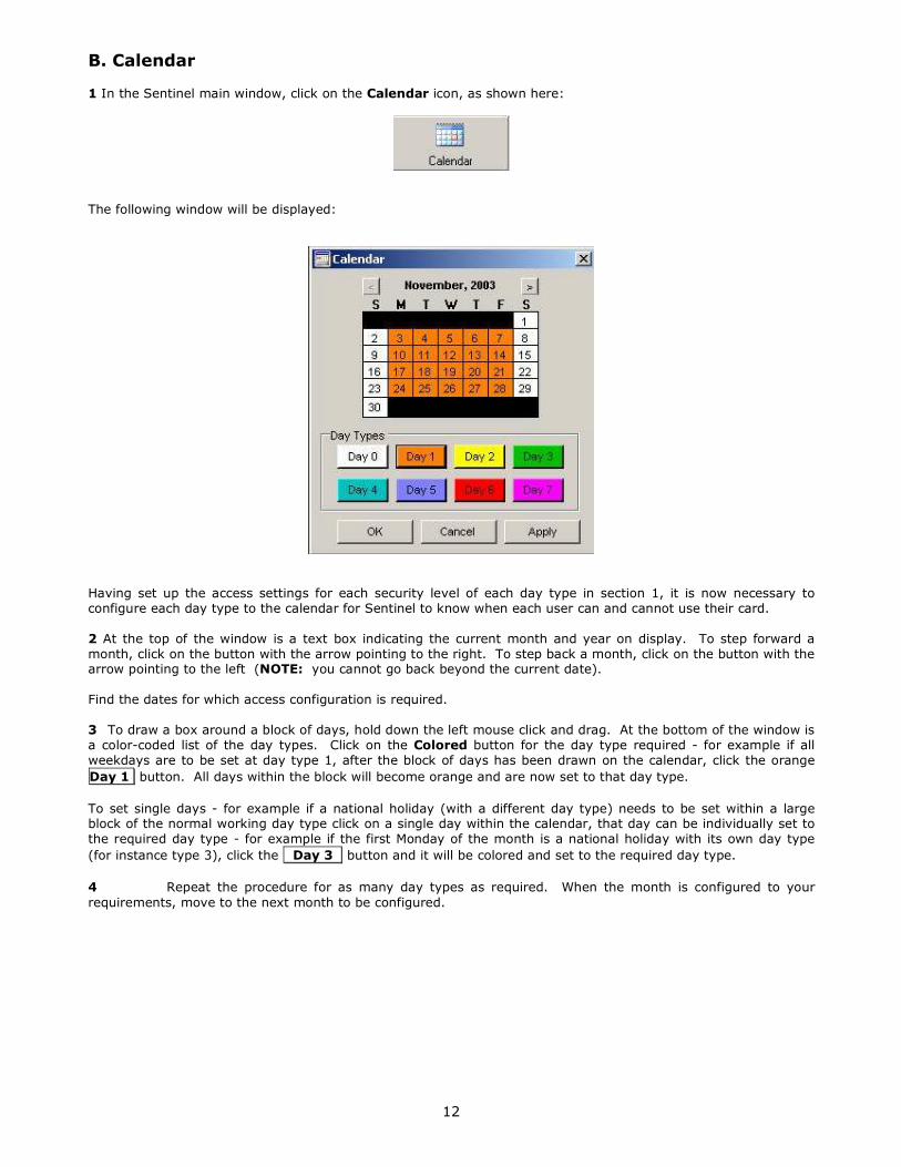
1 In the Sentinel main window, click on the Calendar icon, as shown here:
The following window will be displayed:
Having set up the access settings for each security level of each day type in section 1, it is now necessary to
configure each day type to the calendar for Sentinel to know when each user can and cannot use their card.
2 At the top of the window is a text box indicating the current month and year on display. To step forward a
month, click on the button with the arrow pointing to the right. To step back a month, click on the button with the arrow pointing to the left (NOTE: you cannot go back beyond the current date).
Find the dates for which access configuration is required.
3 To draw a box around a block of days, hold down the left mouse click and drag. At the bottom of the window is
a color-coded list of the day types. Click on the Colored button for the day type required - for example if all
weekdays are to be set at day type 1, after the block of days has been drawn on the calendar, click the orange
Day 1 button. All days within the block will become orange and are now set to that day type.
To set single days - for example if a national holiday (with a different day type) needs to be set within a large block of the normal working day type click on a single day within the calendar, that day can be individually set to
the required day type - for example if the first Monday of the month is a national holiday with its own day type
(for instance type 3), click the Day 3 button and it will be colored and set to the required day type.
4 Repeat the procedure for as many day types as required. When the month is configured to your
requirements, move to the next month to be configured.

13
IMPORTANT:
Any days on the calendar that do not have a day type assigned to them will default to day type 0.
Click the Apply button to ensure the settings are saved.
5 When the calendar has been fully configured as required, click OK to exit the window. The
configurations that have been set will be saved (to exit the window without saving the settings click Cancel).
The ID reader access and security configuration is now complete.
NOTE: If the Data On Unit option is being used, before the ID reader can use these settings they must be
uploaded to the device/s (see the section Uploading Settings to the ID Reader/Access Controller for details
of this procedure).
IMPORTANT NOTE:
With Follow Access Pattern you need to upload the Calendar and Access Times immediately.
1) The Calendar and Access Times must be uploaded to the COMBI on the first day of the year for the
new year to function properly. If not, the default value will be used. The default value is the first day
of the sequence that was last uploaded.
2) The values are good for 360 days or December 31 whichever comes first. The default is then used
which is the first day of the upload.
Example:
On Thursday November 16, 2006 code is uploaded to the Front Door. On Monday January 1, 2007 and
for every day after that until new Calendar and Access Times are uploaded, the Front Door will follow
the access pattern from Thursday November 16, 2006. As soon as the new Calendar and Access
Times are uploaded to the Front Door the values are good for the next 359 days (360 if you count the
current day) or until December 31, 2007 whichever comes first.
It is recommended that you upload on January 1st and around July 1st to keep the tables accurate.

14
Setting Up Users for the ID Reader
IMPORTANT
If you are using a Microsoft Access database, when registering users for the ID reader either the
Sentinel Service needs to be stopped or the server port needs to be changed. Which option is preferred will depend on the set-up of the access control system.
It is recommended that you set up a secondary installation of Sentinel Server software and the
Microsoft.NET Framework on another PC/Workstation. Then to add users and register fingerprints, you
temporarily make that PC the server for the device that will be used to scan fingerprints or codes. If
the device is plugged into the USB of this PC, it is not necessary to make that device the server.
Stopping the Sentinel Service
The Sentinel Service runs in the background and is automatically activated during installation. If this method is
used, when the service is stopped the access control system will be inoperative, thus new users cannot be added at the same time as existing users need access through doors or to clock in/out etc. This is most suitable for
small installations, the more readers/controllers that are on the system, the more impractical this method
becomes.
If you have a newer version of Sentinel.NET, you can stop the service by using the buttons at the top of the
Administration tool window. If you have an older version of Sentinel.NET, how the service is stopped will depend on the version of Windows the PC is running.
2000/XP From the Start menu select Settings/Control Panel/Administrative Tools/Services to display the following
window:
Select Sentinel Service from the list and click the Action button in the upper left corner of the window.
Select Stop. On the list, the status of the service will no longer be listed as Started.
NT4 +
From the Start menu select Settings/Control Panel/Services. Select Sentinel Service from the list and click
the Stop button. On the list, the status of the service will no longer be listed as Started.
95/98/ME
Because these platforms do not run a Services feature the service is run as an executable program. To stop the
service running press Control, Alt and Delete together once to display the Task Manager. Select
Sentinelservice from the list and click the End Task button. The service will be stopped.

15
Changing the Server Port
Sentinel provides the ability to change the server port to allow new users to be registered without stopping the Sentinel Service, if you are using a SQL Server. This enables the access control system to continue to operate so
access can be maintained at all times.
If there is a desktop ID reader/controller that is dedicated to administration and new user set-up only (therefore
doesn’t directly manage a door or a time and attendance terminal), then this controller can be set to this port
permanently to permit easy registration.
If a fingerprint reader/controller that is managing a door or time and attendance terminal needs to be
‘commandeered’ for the registration of new users then changing the port will prevent that particular device from
being used for access control, but because the Sentinel Service is still operating, all other reader/controllers on the network can still function normally.
IMPORTANT: In this situation the server port will need to be changed back to the default setting when the user registration has been completed, allowing the reader/controller access control function to operate again.
Use the following procedure to change the server port:
1 Click on the Network Devices icon at the top of the Sentinel software main window.
2 From the list of available devices select the controller required and click the Properties button.
The General Page will have a Server Port facility.
NOTE: If this feature is not present then the firmware on the device will need to be upgraded - please contact
Ringdale technical support for this (contact details on the back cover of the manual).
The default setting is Server Port 9103
3 Change the server port to another convenient port (suggested 9104, providing this is not already in use - check with the network administrator for this information).
4 Click OK to save the change and exit the window.
When registering a user in either the User Properties’ Fingerprints or Card/PIN windows a similar
facility will be displayed – the port here must be changed to match that set for the server port.
Once either the Sentinel Service is stopped or the server port has been changed, Sentinel is ready to set up new
users for the ID reader.
To set up users for the ID reader, proceed as follows.
1 In the Sentinel main window, click on the Users icon, as shown here.
The following window will be displayed. (NOTE: this picture shows the window with users already configured - on
first time set-up this window will normally be empty)

16
The toolbar at the top of the window has the following options:
New
Click this button to add a new user (see the next point (2) for full details of this).
Edit
This option allows a user’s details to be altered, if required. To access the user’s details, select the name from the
list and click this button.
Remove
To delete a user and all their details, select the name from the list and click this button. It will bring up the following dialogue:
Filter On/Off This option provides a search facility to locate specific users (suitable when there are a large number of users
listed). Click the button to display the following:
This shows the four different criteria that can be used to filter the list of users as required. Click in a text field and
type in a name or security level. Click the funnel button of the same field to find a user or users.
Click the Filter On/Off button again to make this option disappear.
Refresh
If you have a sequel database, multiple users can access it. Refresh to make certain that you have the latest.
Import Users This option allows you to import from an Active Directory or Standard Windows User from a Microsoft Windows
Network.
2 Access Details - To set up a new user click the New button to display the User Properties window as
shown following:

17
3 In the Username field, enter the name of the user.
4 Add a password.
5 Select the Security Access Level for this user from the drop-down box (as set up in the previous section). Typically level 0 grants the most security access.
6 See the ID Card section for using the Add function to add Card/PIN numbers.
IMPORTANT - Click Apply to save this information (other information cannot be entered until this is done). If you
attempt to add parameters before applying, this will warn you.
7 Click on the Contact and Personal tabs to add any further details about the user that are required.
NOTE: Sentinel provides the option to load and store a photograph of the user if required - the system works
perfectly well whether this option is used or not.
To add a photograph, on Access Details page, click on the Browse button and browse to the location of the
file. Click OK and the photo will be displayed in the image box (JPEG, Bitmap and TIF files can all be used). If
the photo is correct click the Save button to store the photo in the database.
8 Select the ID verification option that is required for the user (this will be dependent on the type of ID hardware that is being used with the system).
If an ID card reader is being used on its own, this feature does not need to be set.
The following sections deal with registering a user for ID Card, PIN and fingerprint. Use the sections that are
relevant to your setup.

18
ID Card
To assign an ID card to a user, click on the Add button (located in the Card/PIN Numbers field of the Access
Details page. This will display the following window:
The two methods for assigning an ID number are detailed below:
(i) ID Card Reader with Coded Cards (Pre-Assigned Numbers)
For card readers with coded cards (where each card contains its own unique ‘hidden’ number) ensure that the
From Assigned Unit option is selected, as the number will be automatically entered into Sentinel.
Ensure that the IP address of the assignment unit displayed is the one to be used for reading the cards for registration - to change the required reader/access controller click the Device icon in the Sentinel main window
and right-click over the device’s IP address. From the drop-down menu select Make Assignment Unit. This will
display the unit’s IP address in the Add Card window.
If the port number needs to be changed, click on the Port: xxxx button and set the required port number (see
the Changing the Server Port section earlier in this section for full details on this).
Click the Listen button. Once this button is activated, present the user’s ID card to the card reader. NOTE:
this must be done within 10 seconds.
The number of the card will appear in the Card Number box.
The number can be displayed as decimal or hexadecimal.
Click OK to return to the Access Details page. The number will be displayed in the Card/PIN Numbers field.
(ii) ID Card Reader with Manual Number Entry
If the number of the user’s card is known it can be entered manually.
Ensure that the Enter Manually option is selected.
Enter the ID number into the Card Number box (maximum of ten characters). The number can be displayed as
decimal or hexadecimal.
Click OK to return to the Access Details page. The number will be displayed in the Card/PIN Numbers field.
IMPORTANT: If the Data On Unit option is being used, these details will need to be uploaded to the device
before they will take effect.
19
Keypad PIN (Personal Identification Number) To assign a PIN to a user for use with a keypad, there are two options:
(i) Automatic PIN Generation
Click the Generate Random PIN button.
Click the Generate button and a PIN will be displayed. If the PIN is suitable, click the Accept button
and the number will be assigned.
The PIN will be displayed in the Card Numbers/PIN field of the Access Details page.
(ii) Manual PIN Generation
If there is a specific number that needs to be assigned to the user, then this can be entered manually.
Click on the Add button (located in the Card Numbers/PIN field of the Access Details page.
Ensure that the Enter Manually option is selected.
Enter the ID number into the Card Number box (four characters).
Click OK to return to the Access Details page. The PIN will be displayed in the Card Numbers/PIN field.
IMPORTANT: If the Data On Unit option is being used, these details will need to be uploaded to the device
before they will take effect.
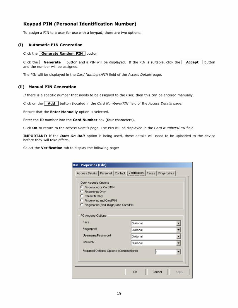
Select the Verification tab to display the following page:

20
In the Door Access Options field, click the radio button that corresponds to the set up required.
Fingerprint Registration Whether using the Standard Capacitive or optional optical USB fingerprint reader for registering users, please read
the details below before commencing.
NOTE: There will be a small minority of people who will be unable to provide a good image of their fingerprint.
For these users there is an option to ensure security is still kept to an optimum. Register the users in the normal
way – for example, select the PIN Only option, assign a PIN - and then change the option to Fingerprint (Bad
Image) and PIN. This will ensure that, once the PIN has been entered, only a user providing a bad fingerprint image will be authenticated. Someone who entered the PIN and then provided a normal image of their fingerprint
would be rejected.
IMPORTANT Information
When using the fingerprint readers please bear the following in mind:
a) Care needs to be taken when setting up users for the fingerprint reader. The more meticulous the approach taken
with this procedure, the clearer and sharper the image will be. The stronger the quality of data that is stored, the
more reliable and consistent will be the access capability of the user. Below are some tips to help achieve this:
i Ensure the fingerprint sensor is clean (use scotch tape) before starting.
ii User’s fingers should be clean (if their hands are washed prior to the start of the procedure, approx. 15 minutes
will be needed for the moisture content of the skin to recover).
iii The lights will flash while the reader is reading a fingerprint. The finger should be held on the sensor for two-three seconds when it has stopped flashing, or until it has beeped. Combi readers have a beep. Solos and Duplos send
the fingerprint to the server and you may not hear it.
iv The fingerprint should cover as much of the sensor as possible. Place the finger directly on the sensor without
sliding across the surface and maintain an even pressure, just enough to get a good full contact. Above all, keep
the finger still.
v Present the finger flat to the sensor as shown below:
NOTE
Movement of the finger while it is in contact with the sensor will stretch the skin and thus distort the fingerprint, making a clear reading more difficult. Similarly, pressing too hard on the Standard (Capacitive) reader will also
distort the fingerprint. Avoiding these common mistakes can greatly improve the consistency of recognition.
b) Every finger registered will need to be processed four times to ensure a thorough identification is possible.
c) It is recommended that each individual register two or three fingers. There will then be a backup fingerprint that can be used in the event of one of the fingerprints becomes temporarily or permanently altered (for example by a
paper cut or minor burn).
d) It is useful to have the fingerprint reader close to the Sentinel Server, or a PC running Sentinel.NET software,
when setting up new users.
Use the following procedure to register a fingerprint:
1 Click on the Fingerprints tab to move from the Access Details page to the Fingerprints page. An example is shown below (NOTE: this example is shown with a fingerprint, when viewing for the first time the window will be
empty):

21
If the port number needs to be changed, click on the Port: 9103 button and set the required port number
(see the Changing the Server Port section earlier in this section for full details on this).
2 Click on the radio button for the first finger that is to be registered. The finger selected will be confirmed.
3 Click on the button and ask the user to apply the correct finger to the sensor of the fingerprint reader. After a few seconds the fingerprint will be displayed on the Fingerprint page.
It is important to get as clean an image of the fingerprint as possible. Don’t be afraid to redo the fingerprint if the
image displayed is poor. The better the data held for each finger by Sentinel the more reliable will be the
recognition by the reader in everyday use.
Don’t forget to employ the tips detailed at the start of this section to achieve consistent results of a
high standard.
4 Two buttons will now be enabled – Verify and Start Enrolment.
Click the button. This allows the print to be verified to ensure that it does not match too closely an existing
print in the database. If this occurs, ask the user to select another finger for registration. After the button
has been clicked the following will be displayed:
Click the OK button and if happy with the fingerprint click the Start Enrolment button to hold this print
as the first of the four that are needed for each finger that is to be registered.
NOTE: The Same finger will need to be presented three additional times in total, and will be matched to the first
fingerprint - this is to allow Sentinel to learn to recognize the fingerprint.
5 The page will now be displaying a message ‘Waiting for Print 2’. Ask the user to apply the same finger to the
sensor of the fingerprint reader again. Click the Verify button once more. This time the following should be
displayed:

22
If the fingerprint image is strong enough, the software will display a score that is matched to the first fingerprint.
The match score shows how successfully Sentinel is recognizing each fingerprint.
Any score over 170 is very good. It is recommended that scores lower than 130 be rejected.
Click the OK button. If the score is unsatisfactory, click the Cancel button and restart the procedure and
click Verify again until a successful match is achieved. If happy with the score - as in the previous example shown - then ask the user to present their fingerprint again.
6 Repeat the step five for the third and fourth fingerprints.
After each stage check the finger diagram to ensure that the fingerprints are being matched to the correct finger.
At the end of the procedure, the fingerprints can be viewed by clicking on the View button. An example of the
Fingerprint Image Viewer window is shown following. If the quality of the images is not high, do not be afraid to
start again.
Clicking the button will clear all of the held images for that finger to start again with a clean slate. When the registration is complete, it will say enrolment complete.
Do not click the Re Enroll Fingerprints button unless you wish to delete all fingerprint data for all fingers held
for that user.
7 Try two or three tests to check the access capability of the user by getting the user to provide additional
fingerprints. Click the button after each print appears on the Fingerprint page. The print should be identified with a matching score of consistently over 200. Routine scores below this will require the registration
procedure to be repeated to improve recognition. Click Apply to save the data.
8 Repeat the registration procedure for each additional finger for that user (it is recommended that two or three
fingers are registered for each user).
The user set-up procedure is now complete. Click the OK button to close the window saving all the
information and the user’s name will appear on the list in the Users window.
The user can now be associated to specific groups and specific ID readers (see the section Managing Users for More than One ID Reader to complete the user configuration procedures).

23
IMPORTANT: Until the user has been assigned to a group (and that group is assigned to the device), they will not
be able to use their ID to gain access. Complete the full configuration procedures before attempting use.
Repeat the procedures detailed in this section to set up as many users as required.
IMPORTANT: See the next section for details on restarting the Sentinel Service or changing the device’s server port back to default - which may or may not be required.
Restarting the Sentinel Service
IMPORTANT: If the Stop Sentinel Service method has been used, When user registration is finished it
is necessary to restart the service before the system can operate. How the service is started again will depend on the version of Windows the PC is running.
2000 From the Start menu select Settings/Control Panel/Administrative Tools/Component Services. Select
Sentinel – Sentinel Service from the list and click the Action button in the upper left corner of the window.
Select Start. On the list, the status of the service will now be listed as Started.
NT4 + From the Start menu select Settings/Control Panel/Services. Select Sentinel Service from the list and click
the Start button. On the list, the status of the service will now be listed as Started.
95/98/ME Because these platforms do not run a Services feature the service is run as an executable program. Use the
following procedure to restart the Sentinel Service:
1 Using Windows Explorer, navigate to the location of the Sentinel program files (normally C:\Program
Files\Ringdale\Sentinel .NET).
2 From the Start menu select Run and then drag the Sentinel Service details from Explorer into the Run dialog box as shown in the example below:
3 Scroll along to the end of the text thread and type 1 blank space, then -exe (no spaces between the minus and the letters) as shown in the example above.
The complete text should now read: C:\Program Files\Ringdale\Sentinel .NET\SentinelService.exe -exe
4 Click the OK button and the Sentinel Service will be restarted (this can be checked by clicking the Control, Alt
and Delete keys at the same time (once only) - Sentinel Service will be listed among the programs running).

24
Changing Back the Server Port for the Controller
IMPORTANT: If the Changing the Server Port method has been used, and the device used for
registration is NOT a dedicated ‘registration only’ unit, the ID reader/access controller device needs to be reset to the previous server port.
If a dedicated desktop fingerprint reader and controller are being used for administration and registration
purposes (and are not being used to directly manage a door or Time and Attendance terminal) then the server
port should remain as set for registration.
Perform the following procedure only if the device needs to directly manage access control as in the first of the above situations:
1 Click on the Network Devices icon at the top of the Sentinel software main window.
2 From the list of available devices select the controller required and click the Properties button to display the
Device Properties window.
3 In the Server Port field, change the server port back to its original setting (normally 9103).
4 Click OK to save the change and exit the window.
The device is now prepared for access control once again.

25
Assigning Users to a Group and Managing Users for more than One ID Reader
IMPORTANT: ALL users must be included in at least one group
For situations where more than one ID reader is being used on the network, Sentinel provides a group
management feature. This allows the list of users to be divided into groups. Each group can then be assigned to a particular ID reader or readers as required.
If there is only one reader operating, and all users need to use that reader, only one group needs to be created and all the users can be put in that group. Otherwise, more comprehensive setup is required.
A simple example of this feature in operation would be:
Company B has two ID readers.
Reader 1 is for the main entrance
Reader 2 is for access to the accounts office
All employees require entry through the main door. Only accounts employees have entry to the accounts office.
A group is created for the main entrance and all the users are assigned to it. This group is then assigned to reader 1.
A second group is created for accounts employees. This group is then assigned to reader 2. Only employees in this group can access the accounts office.
Use the following procedure to create a group and assign the group to the required ID reader.
1 In the Sentinel main window, click on the Groups icon, as shown here.
The following window will be displayed:
This window will display a list of all user groups that have been set up in Sentinel (NOTE: this window will be empty when setting up user groups for the first time).
In the example shown all users are included in the group for the main door, but it is not necessary to create a
group specifically for all users (though this does ensure that no user gets missed).

26
The toolbar at the top of the window has the following options:
New Click this button to add a new group (see the next point (2) for full details of this).
Edit This option allows a group’s details to be altered, if required. To access a group’s details, select the group from
the list and click this button.
Remove
To delete a group, select the group from the list and click this button. IMPORTANT: If a group is deleted, any
users who belong to that group only will lose their access rights. It will be necessary to assign the users to another group.
Filter On/Off This option provides a search facility to locate specific groups (suitable when there are a large number of groups
listed). Click the button to display the following:
This shows the two different criteria that can be used to filter the list of groups as required. Click in a text field
and type in a name or description. Click the funnel button of the same field to find a group.
Click the Filter On/Off button again to make this option disappear.
2 Click on the New button to display the Details page of the Group Properties window. Enter a Title for the
group and then enter a brief description of the group into the Description field (maximum 50 characters).
3 Click on the Members tab to display the following page:
In the All Available Users field will be listed all the users that have been set up within Sentinel. Select a user or
users that are to be members of the group from this field.

27
To select multiple users hold down the Control key while selecting, or to select a block of users together hold
down the Shift key and select the users at the top and bottom of the block.
Click the Add User(s) button and the selected user/s will be moved into the Users in This Group field.
Repeat the procedure until all users required for this group are in the lower field.
If a user or users need to be removed from the group list, select them following the same method as above but in
the lower field. Click the Remove User(s) button and the users will be moved back to the top list.
4 Click on the Devices tab to display the following page:
On this page, assign a specific ID reader or readers and door locks to the group. In the All Available Devices
field will be listed all the ID readers/access controllers that have been set up within Sentinel. Select a device or
devices that are to be associated with this group from this field.
To select multiple devices hold down the Control key while selecting, or to select a block of devices together hold
down the Shift key and select the devices at the top and bottom of the block.
If the Duplo version of the hardware is being used, each device can operate up to two door strikes (locks). On the
bottom half of the page there are two different fields in which each of the two locks for each device can be
assigned to the group. The left field refers to Lock 1, and the right field to Lock 2.
NOTE: If the Solo version of the controller is being used, only the Lock 1 (left field) is to be used.
Click the Add Device(s) button for the lock required and the selected device/s will be listed in the Lock field.
As two different ID readers can be operated from one controller device, the same device can be assigned to both Lock fields if both locks that device is operating are to be assigned to this group.
If a device needs to be removed from the group list, select the device from either of the Lock fields and click the
Remove Device(s) button. The device will be unassigned from the group.
5 Click OK to exit the window saving the settings. The new group will be listed in the Groups window.
Repeat procedure to set up as many groups as required.
IMPORTANT: Before attempting to use the system, ensure that the lock has been configured – see the
following section Door Strike and Bolt Control Options for details on this.

28
Changing Group Configurations
To make changes to a group set-up, select the group from the list displayed in the Groups window and click the
Edit button.
The Group Properties window will be displayed with the three pages Details, Members and Devices. To alter the
set-up follow the same instructions as previously described in this section. Change, add and remove users and
devices as required.
Click OK to exit the window saving the changes.
Deleting Groups
To delete a group from the Groups List, select the group and click on the Remove button. The group will be
removed.
IMPORTANT: If a group is deleted, any users who belong to that group only will lose their access rights. It will be necessary to assign the users to another group.
IMPORTANT: If the Data On Unit option is being used, these details will need to be uploaded to the device
before they will take effect. See the section Uploading Settings to the ID Reader/Access Controller.

29
Door Strike and Bolt Control Options
Sentinel gives the ability to remotely control the set-up and operation of a door strike or bolt if the ID
reader/access controller is managing this kind of device (this option will not be present if the ID
reader/access controller is being used to manage a time and attendance terminal - see the separate
section for details of the different options available with this feature).
IMPORTANT: The correct door strike or bolt type MUST be set in Sentinel before attempting to use
the device.
Access the control options as follows:
1 In the Sentinel main window, click on the Network Devices icon to display a
list of the available devices on the network.
2 From the list, select the device that is managing the door strike or bolt and open the property
pages. Select the Locks tab to display the following page
IMPORTANT NOTE: This page has the capability to manage two different locks. This is for use with
the Duplo version of the access controller that can manage two locks simultaneously - or alternatively two ID readers on one lock. If the Solo version is being used, then only use the Lock
One (left) field:
This page provides the ability to remotely operate the lock or to override the current operation
settings.
3 In the Lock Timeout box enter the amount of time in seconds that the lock will be ‘live’ for once
activated by a successful ID (for example, a five second timeout would give a user five seconds to
access the door after ID recognition before the door would lock again).

30
NOTE: If the Lock Timeout is set to zero, the lock will enter ‘toggle mode’. This means that the
door will open after the first successful ID, and will then remain open until another successful ID is
made, whereupon it will lock again, until the next ID when it will open again, etc.
The following options are available for the lock operation; select the option required:
Normal
The most commonly used option. Select this option for the system to operate to the access and
security settings as set up in Sentinel.
Permanently Closed
Select this option to keep the lock permanently closed.
Permanently Open
Select this option to keep the lock permanently open.
Follows Access Pattern
This option allows greater flexibility in the strike/bolt management by allowing the access controller to be associated with one of the Security Access Levels set up in the Access Times
window (see the Access and Security Settings section). Once associated to a specific level,
general access can be provided for a specified period, while restricted access is allowed outside the
period. Following is a typical example of this feature in operation:
Store XYZ has an ID reader by its main door. The store opens from 10:00 am to 4:00 pm. During
this time the door needs to be open for customers to come and go, so no ID is needed during this time to gain entry.
Access Level 5 is set at 10:00 am till 4:00 pm. The door strike is set to follow this access pattern. Unrestricted access is granted through the main door for this period.
Before 10:00 am and after 4:00 pm, an ID will be needed to gain access through the door and the door will lock again after use, enabling staff to enter.
The access level they have been assigned will regulate the period the staff can enter. For example, general staff will only be able to enter between 8:30 am and 6:00 pm. Managers will
have 24-hour access.
The door strike will automatically activate at 4:00 pm, so an ID will be needed to gain access from
this time. However, the lock will not automatically deactivate at 10:00 am. An ID will be
needed to gain entry the first time after 10:00 am to ensure complete security.
Set the strike to follow the access pattern by selecting the level required from the drop-down list
after selecting the Follows Access Pattern option.
Open Now
This button gives the ability to remotely open the door using the Sentinel software - directly from
the workstation.

31
4 Click on the Physical Lock Types tab to display the following page. This page has the capability
to manage two different locks. This is for use with the Duplo version. If you have the Solo version
only the Lock One field should be used:
In the Type field, select the type of lock that the access controller is connecting to:
Standard Strike – Most third party locks will be Standard. If using a Ringdale door strike this will be labeled.
.
Pulse Strike – If the door strike is of the Pulse variety, this will be indicated on the label.
Standard Bolt – If a Ringdale bolt is being used, select this option.
(Optional and only applies if a pulse door strike is fitted) tick the Side Pressure Pulsing box to
allow a pulse strike to re-fire if side pressure is being applied to it when activated - preventing it
from being able to release the door (for example if someone is leaning on the door as an ID is accepted).
If a Ringdale brand strike is connected the Logic field will become active. Select whether the
strike is of the Lock Fails Closed (PTO) type or the Lock Fails Open (PTL) type (this will be detailed on the strike itself).

32
5 The Input (Readers) function is for fingerprint readers only. If a fingerprint reader is being used,
click on the Input (Readers) tab. This will display the following page:
This option allows the fingerprint reader sensitivity to be adjusted to the environment within which
it will be operating. The more humid the environment the higher the reader will need to be set. Click and drag the slider to adjust. In dry conditions the threshold can be set lower. Return to the
default setting at any time by clicking the Default button.

33
6 Click on the Input Channels 1 (Readers) tab to display the following page (the access controller runs two
channels, enabling up to two readers to be connected):
For each reader, select which lock to operate, 1, 2 or both.
If required, that particular reader can be set to override the instructions set for the access controller on the Locks
page.
Tick the Follow Access Pattern box to allow the locks operated by the reader to work to the access pattern set
up in the Access Settings window.
Ticking the Permanently Open/Closed box will keep the lock open or closed depending on the logic of the lock.
Tick the On First Identification (When Following Access Pattern) to open the door after the first successful ID of the access pattern period, after which the door will then remain open until another identification will close it
when the access pattern period has finished. An example of this would be a shop open from 9:00 am to 6:00 pm.
The first successful ID after nine would unlock the door, and it would remain open until the next successful ID after six, when the door would lock until nine the following morning.
7 Click on the Input Channel 2 (Button Release) tab Only if a button release option has been fitted to the controller – this will be a button situated on the ‘secure’ side of the door which will allow a user to exit the secure
area (for example, if the lock is being used with a walk-in cupboard). Again, there will be two channels, enabling
up to two button releases to be connected to two different locks.
Select which lock each channel will operate, 1, 2 or both.
Again, if required, that particular channel can be set to allow access while these instructions are set for the
controller on the Locks page. Tick the Following Pattern or Locked State boxes to allow the button release to
permit an exit even if these options are selected on the Locks page.
You can also change the button release circuit to either Normally Open (default) or to Normally Closed.

34
8 Click on the Input Channel 3 (Alarm) tab. The lock will be disabled to allow free access while enabled only if a
permanent release button option (e.g. fire alarm) has been fitted to the controller. Again, there will be two
channels, enabling up to two alarm button releases to be connected to two different locks.
Select which lock each channel will operate, 1, 2 or both.
Again, you can also change the button release circuit to either Normally Open (default) or to Normally Closed.
9 Click Apply to save any settings that have been made, or OK to exit the property pages saving any changes.
Quick Select Options
The following lock control features are available as quick select options by Right clicking over the required device on the list in the Devices window to display the pop-up menu shown here:
Select the Extra option to display the secondary menu. Select the option as required.

35
Uploading Settings to the ID Reader/Access Controller
This section is only for those installations that are using the Data On Unit option (see the section
Configuring an ID Reader/Access Controller to the Network for details on this).
Once the users, groups and access and security settings are configured, or whenever any changes have been made to these settings, it is necessary to upload the information to the ID readers/access controllers themselves.
This MUST be done for the new settings to take effect. Upload the settings using one of the two following
procedures:
a) Quick Upload Method to Single ID Reader/Access Controller
Use this method to upload the settings separately to one ID reader only.
1 In the main window of Sentinel, click on the Devices icon to display the list of ID readers/access controllers
available.
2 Right click over the required device on the list to display the following pop-up window:
3 Select the Upload option to display the three additional options shown above.
(i) Selecting Calendar will upload the up-to-date calendar settings as currently configured in Sentinel to the ID reader required.
(ii) Selecting Access will upload the security access patterns for each day type as currently configured in Sentinel to the ID reader required.
(iii) To upload all details of groups associated to that particular device select Groups. All users set up in those groups will be assigned to that ID reader (if, for example, a user has been recently added or removed from one of
these groups, uploading the revised groups will instantly make the ID reader up-to-date with the information from
Sentinel).
b) Multiple Upload Method Using the Upload Wizard
For a more comprehensive and flexible method to update the ID readers/access controllers with the latest information use the Upload Wizard.
1 In the main window of Sentinel, click on the Upload icon, as shown here.

36
The first window of the wizard is shown following:
Here will be listed all of the ID readers/access controllers on the network - if all devices are not displayed here
click on the Requery Network button.
2 Select the device/s from the list that are to be uploaded with the new information.
To select multiple devices hold down the Control key while selecting, or to select a block of devices together hold
down the Shift key and select the device at the top and bottom of the block.
To select all devices click on the Select All button.
Click on the Deselect All button to clear any incorrect selections that have been made. You would need to
then re-select the specific devices to upload.
3 When the devices required are selected click on the Next button to display the following window (NOTE: If a
password has been set it will need to be entered at this point to continue with the wizard):
4 Select which data is to be uploaded (any combination of the three types can be uploaded at the same time).
Selecting Access Times will upload the security access patterns for each day type as currently configured in the
software to the chosen ID readers/access controllers.

37
Selecting Calendar will upload the calendar settings for up to 360 days as currently configured in the software to
the chosen ID readers/access controllers.
If either or both of these options are selected without the Users option, then click Next to skip straight to the
Step 4 wizard window.
IMPORTANT NOTE: Combi readers always maintain the data on the server. Do not enable the Users function if
you have a Combi reader.
Selecting Users is a function that should only be used for Solo or Duplo readers. It will provide a choice of two
options:
a) Choosing Groups to Devices will upload all associated user groups and their details (including security levels)
as currently configured in the software to the ID readers/access controllers that have been selected.
If this option is selected click the Next button to skip straight to the Step 4 wizard window.
b) Choosing the Selected Groups option and clicking the Next button will display the following Step 3 wizard
window:
This window will display the list of all user groups currently available in Sentinel. From the list select
the user group/s to be uploaded to the chosen ID readers/access controllers.
To select multiple groups hold down the Control key while selecting, or to select a block of groups
together hold down the Shift key and select the group at the top and bottom of the block.
To select all groups click on the Select All button.
Click on the Deselect All button to clear any incorrect selections that have been made and re-
select the groups.
IMPORTANT
Care needs to be taken with this procedure - using the Select All button will assign
every group to the selected ID readers/access controllers and give all users access
through those devices. Similarly, selecting the wrong group by mistake will give that
group access through the device whether the device is associated to the group or not.
38
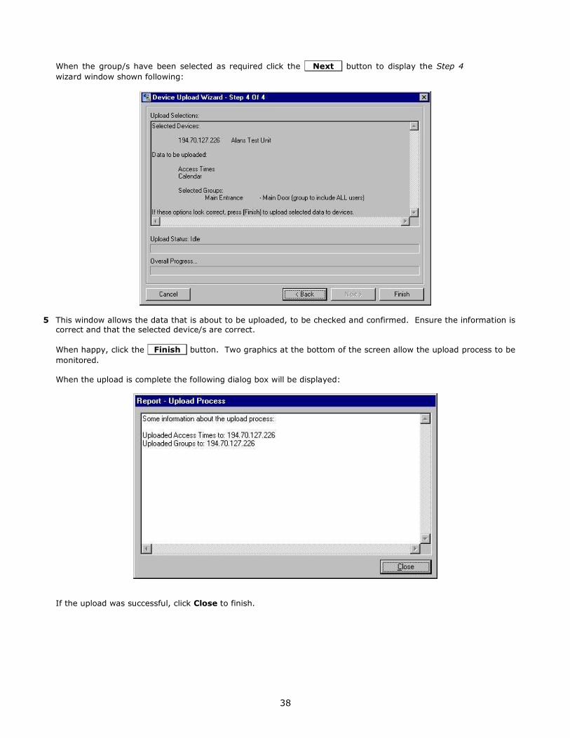
When the group/s have been selected as required click the Next button to display the Step 4
wizard window shown following:
5 This window allows the data that is about to be uploaded, to be checked and confirmed. Ensure the information is
correct and that the selected device/s are correct.
When happy, click the Finish button. Two graphics at the bottom of the screen allow the upload process to be
monitored.
When the upload is complete the following dialog box will be displayed:
If the upload was successful, click Close to finish.

39
Time and Attendance Terminal
If the ID reader/access controller is being used to manage a time and attendance terminal, an alternative General
Page will be present instead of the door strike and bolt control options. This will need to be configured to ensure
accurate time keeping. To access the page:
1 In the Sentinel main window, click on the Network Devices icon to display a list of the available devices on the network.
2 From the list, select the device that is managing the time and attendance terminal and open the property pages.
3 On the General page there will be an additional button, Reset Screen . Click this to reset the LCD touch
screen at any time required.
4 Select the Date & Time tab to display the following page:
NOTE: All timeservers send the time in Greenwich Meantime. You can either enter the IP addresses of up to
three external Time Servers and set the Time Zone Offset from GMT and configure the Daylight Saving Time settings, or you can disable the Sentinel Server’s – “Windows Time” Service and use the Sentinel Server clock by
entering that as the IP address. If you use the Sentinel Server for the time, you should leave the Time Zone
Offset from GMT set to +00:00 and NOT enable the Daylight Saving Time, but instead rely on the clock on the
server that runs Sentinel Server for Daylight Saving Time.
If you choose to use external time servers, there is a list of public timeservers at this URL:
http://tf.nist.gov/service/time-servers.html If you use external time servers, you must adjust your Time Zone Offset in order to set the time correctly.
If you choose to use the Sentinel Server clock, you must disable the “Windows Time” Service. This is handled in
the Administrative Tools, Component Services. Click the Start button, then Settings, Control Panel. Select
Administrative Tools, then Component Services. Select Services (Local) and then scroll down to
Windows Time. Double-click it and select Stop. If the clock in the lower right of the Windows screen is correct, the Sentinel device clocks will be correct.

40
NOTE: Time changes are sent to the attached readers every hour. If you need to update a reader immediately,
change it’s name and then change it back.
5 Under Time Servers, enter either the main Sentinel Server IP Address, or up to three IP addresses of Time
Servers in the boxes provided. The device will set its time by contacting the first address. If the first address
fails to respond the second address will be contacted. The third address will only be contacted if the first two time servers cannot be contacted. If you use multiple timeservers they must all be Internet Time Server that at
set at GMT, so that you can use the same Time Zone Offset.
6 Time Zone Offset from GMT must be changed if you use external time servers. All time servers are set to
GMT. In the field it is necessary to set the time zone that the terminal is in. If you are in Greenwich, England,
this number will be 0. If your time zone is east of Greenwich, England), the number is positive. If your time zone is west of GMT, the number is negative. For EST, use –5, CST –6, MST –7, PST –8, AKST –9, and HAST –10.
7 Daylight Saving Time must be changed if you use external time servers. The terminal can be set to automatically adjust to Daylight Saving Time/British Summer Time if required. Tick the Enabled box to activate
the feature and enter the Start Date and Start Time, and the End Date and End Time for DST/BST for the
year of operation.
8 Click Apply/OK to save the information.

41
Retrieving Information from the ID Reader/Access Controller
IMPORTANT: All fingerprint readers, and combi ID readers that have a fingerprint reader, will automatically be set
to real time retrieval. The amount of data generated for a fingerprint is too large to store on the
controller itself. This cannot be changed. In this case move onto the next section Creating Reports.
In order to create reports, Sentinel retrieves the data logs from the ID reader/access controller. This allows each
device’s use to be monitored (see the separate section Creating Reports for more details of this). The information is stored in either a Microsoft Access or SQL database depending on the option chosen on installation (see the
section First Time Set-Up Procedure for details on setting up the database).
The information displayed in a report will only be that data that has been retrieved by Sentinel. If not running a fingerprint reader, retrieval runs automatically every ten minutes to ensure the data is kept up-to-date, but the
option is provided to download the current data from any or all ID readers/access controllers in real time
(depending on the level of network traffic), ensuring that the software always has the absolute latest information.
IMPORTANT: To reduce network traffic, it is recommended that this facility be only used for multiple
devices when absolutely necessary.
Typically, this facility can be used at a time that a report is to be generated, if complete up-to-date data is
required. The access controller/s being used for the report are set to real time retrieval, the report is then generated and the controller/s can then be put back to the default ten-minute retrieval status.
Use the following procedure to set access controllers to real time retrieval:
NOTE: Ensure that the database is correctly set up before starting (see the section First Time Set-Up Procedure
for details).
1 In the Sentinel main window, select the Logging option from the Tools drop-down menu to display the window
shown following.
2 This will display a list of the access controllers. Tick the check box for the controllers that are to be set for real
time retrieval.
To select multiple devices, hold down the Control key and click on the controller name for each, or to select a
block of devices together hold down the Shift key and select the device at the top and bottom of the block.

42
Right click any of the device fields to display a pop-up menu with the possible options:
Check Selected (Require Password)
Clear Selected (Do Not Require Password)
Set Password for Selected Items
Clear Password for Selected Items
Select Check Selected (Require Password) to select all those controllers – they will automatically be ticked in
the check boxes.
IMPORTANT: if a password was set for Sentinel during the set-up procedure (see the section
Configuring an ID Reader/Access Controller to the Network for details of this) it will need to be
entered here before the selection can be made.
To use the multiple selection methods all the controllers will need to have been given the same
password.
3 Click OK and those devices selected will now be set to real time retrieval.
NOTE
The right click pop-up window here also offers an alternative place to set up a password for the controllers to restrict access to change any data within Sentinel (the device property pages provide the same option). It is
strongly recommended that a password be used.
Select the Set Password for Selected Items to set a password.
To remove a password, select Clear Password for Selected Items.
Removing Real Time Retrieval
To return an access controller to the default ten minute retrieval repeat the procedure described above, either
untick the check boxes or with multiple selections select the Clear Selected (Do Not Require Password) option
from the right click pop-up menu.

43
Serial / USB Devices
This function is only for users with the old Duplo and Solo devices. With those devices you had to make the
connection between each fingerprint reader and locking device.
Click on the Serial / USB Devices icon.
It will bring up the list of serial and USB devices on your network. These include Fingerprint readers and scanners.

44
If you double-click on a device it will bring up the properties.

45
The Users tab brings up the following options:
In this panel, you add the users who are allowed to use each Fingerprint Reader.

46
The Users tab brings up the following options:
In this panel, you add the locking devices that are controlled by each Fingerprint Reader.

47
Remote Administration
Sentinel gives the ability to remotely control the set-up and operation the system to those who have installed
Microsoft.net and the Sentinel software.
Access the remote administration by clicking on the icon.
It will bring up the following window:
Click Add IP Address – Computer Name to bring up the following dialogue box:

48
Creating Reports
NOTE: If using an ID reader that Does Not have a fingerprint reader and which is set to automatic ten minute
retrieval, see the section Retrieving Information from the ID Reader/Access Controller to ensure all the data that is
required for the report has been downloaded.
There are four types of reports that can be created:
Activity Reports
This option allows the generation of reports based on the information downloaded from each controller, including when access was granted, who to, which device etc.
Attendance Reports This option is primarily for use with controllers that are managing a time and attendance system. It can be used
to generate a report from the clock in/clock out data.
Groups and Users
This option allows a simple list of the existing groups and the users assigned to those groups to be printed out.
User Information This option allows a list of selected users and their full details to be printed out.
To access the report creation features, click on the Reports icon at the top of the Sentinel main window as shown here.
From the Please Select a Report drop-down menu at the top of the displayed window, select the option for the
type of report to be generated.
Following are details on how to generate an Activity Report, followed by an example of a report and the options
available once the report has been generated. The procedure for generating other reports will be very similar to
this:
1 Ensure that the Activity Reports option is selected from the drop-down menu at the top of the Reports window
(this is the default option, so should be displayed automatically – the other report options are selected from here
too). An example of the window is shown following:

49
2 From the "From" drop-down calendar select the month and day that the report should start from.
3 From the “To” drop-down calendar select the month and day where the report should finish.
To create a report for just one day, set the same “From” and “To” dates.
4 Beneath this field will be three tabs (users, groups, and devices), Select “Users” to see a list of all users registered
on Sentinel. From the list, select the user/s whose log should be used to create the report.
To select multiple users hold down the Control key while selecting, or to select a block of users together hold
down the Shift key and select the users at the top and bottom of the block.
NOTE: Sentinel possesses a great deal of adaptability. It is not necessary to select any users at all from this page
unless specifically required. For example, if the report requires a list of all users in a certain group, then click on the Groups tab and select the group on that page – all the users in that group will be included in the report.
Similarly, if the Devices tab is clicked, and an access controller is selected from the list on that page, all users
assigned to that device will be included in the report. This avoids the need to trawl through all the users in the list when generating the report.
5 Click on the Add User(s) button and all the selected users will be moved to the lower field (Users Included in
Report).
To remove a user from this list, simply reverse the procedure – select the user from the lower field and click the
Remove User(s) button.
6 Use the same procedure on the Groups and Devices pages to select the information required in the report.
7 To generate the report click the Run Report button.
NOTE: Be aware that if there are a lot of users and controllers set up in Sentinel and the system is heavily used, creating a report with several devices can produce a large amount of data. The report might take a few moments
to generate depending on the amount of data to be processed.

50
Example Report
Below is a simple example of a generated report:
The information requested for this report was:
Dates: 20th November 2003 Only.
Users Selected: None
Groups Selected: None
Devices Selected: Demo Unit Only – IP address 10.20.30.2
So the report displays all activity for the above controller on that day – which in this case shows that the three
named users have accessed the door three times each, with each time clearly shown.
To assist with reports containing a large amount of data, users and groups will be listed in the tree scheme in the
left of the window. If there is a large report containing many pages, this can be used to find a person quickly.
The tree scheme can be turned on and off using a button on the menu bar above.
The features in the menu bar are as follows:
Arrow Buttons
Use these buttons to navigate through the report if it contains many pages. Options included are Next Page,
Previous Page, Go to End of Report, Return to Start of Report and Select the Page Number Required.
Use this button to print out the report.
Refresh
Use this button to refresh the window.

51
Export Report
Use this button if a permanent record of the report is required. This will open a Save As window. Browse to the
location where the file is to be stored, name the file and select the format it is to be saved in. Formats available
include:
Adobe Acrobat PDF File – It is not necessary to have acrobat installed to create the PDF, but a PC will need
Acrobat Reader installed to view the file.
Microsoft Excel
Microsoft Word
Rich Text Format (RTF)
Toggle Tree Scheme
Use this button to open and close the tree feature (see above).
Zoom
Click on the arrow to open a drop-down list of the options available for viewing the report.
Search Text
This option provides a quick method of finding data in a large report. Enter the text required (for example a user’s
name) and each appearance of the word will be located in order.
Font
Use this button to alter the appearance of the report as required – select the font required from the list.
Color
Use this button to alter the appearance of the report as required – select the color of the font.

52
Sentinel Installation and Product Authorization
Installation
Things are the steps required to install a basic Sentinel Server.
1) Install Microsoft.Net Framework.
2) Install Sentinel software.
3) Register the Sentinel software on the Ringdale website.
4) Point the Sentinel software to the SQL or Access database using the Tools / Database Settings.
5) Configure the Access Times for the system.
6) Configure the calendar in the Sentinel software.
7) Locate and configure the Network Devices.
8) Add Users and register their fingerprints and / or IDs.
9) Add Users to Groups.
IMPORTANT: Microsoft.Net Framework is required to run the Sentinel software. It must be installed before
attempting installation of the Sentinel Software. It comes with Windows XP Professional. The version 1.1 is
included on the Sentinel CD. Sentinel works with version 2.0 as well. This can be obtained from the Microsoft website by searching on Microsoft.Net Framework.
NOTE: You must be logged on with Administrator privileges in order to perform these tasks.
NOTE: It is recommended that older versions of Sentinel be uninstalled before a new version is installed. If using
the Access database option the data held by the old version of Sentinel will not be lost as this is stored in a
separate .mdb Microsoft Access file which is not deleted - ensure that the new version of Sentinel is directed to this file to hold onto the data (or to the SQL database if that option is being used). To be absolutely safe, it is
recommended that the .mdb file be copied to a backup location before starting the procedure.
The Sentinel software is found on the CD enclosed with the pack. The software can be installed on any networked
Windows 98/NT4/2000/XP Professional PC.
Use the following procedure to install the software:
1 Load the CD into the PC’s CD drive.
2 Use Windows Explorer to browse the CD and select the Sentinel directory.
3 The program is named Sentinel_Server.exe. Double click to start the installation.
4 Follow the on screen instructions to complete the installation.

53
Product Authorization
After installation, the Sentinel.NET software will need to be authorized before it can be used.
IMPORTANT NOTE: Without authorization the Sentinel software will not be able to be used. You can use the software in evaluation mode for up to 5 clients.
1 Open Sentinel by selecting: “Start/Programs/Ringdale/ Sentinel.Net/Sentinel.Net”
A message will state that the database is not yet connected. Click OK.
2 Another message will state that the software is not registered. Click OK again and the following dialog box will
be displayed:
3 Click on the Copy to Clipboard button.
4 Using a web browser, access the Ringdale website at:
www.ringdale.com
5 From the drop-down menus at the top of the page, select My Account.
6 It will be necessary to login with an E-mail address and password – for first time users it will be necessary to create a new account. After login click on the “Downloads and Registration” option.
7 If you have already purchased the software and wish to register it, it will be assigned to your email address and
you will see it under Register Software. You may need to click on the button.
NOTE: The procedure to register an evaluation is the same as the procedure to register purchased licenses. The
Sentinel Standard version gives you 5 CALs (Client Access Licenses). Professional gives you 50 CALs and Enterprises gives you 100. Additional CALs can be purchased in bundles.
If you are going to evaluate the software before purchasing it, use the “Evaluation, Standard and
Administration Tool Only Editions” menus.

54
If the button next to “Evaluation, Standard and Administration Tool Only Editions” says ,
click on it.
6 From Select Product choose Sentinel-Standard, or if you purchased it, select the appropriate version under
the Register Software.
7 Paste the Registration Key into the Registration Key text box provided and click the button.
8 The registration key will be supplied. Copy the registration key to the clipboard and paste it into the License Key text box of the Registration dialog box for the Sentinel software.
NOTE: This code will only be valid for the specific PC from which the original registration key was generated.
9 Click the Verify License Key button. A dialog box will confirm that the license is valid.

55
10 Click OK twice to complete the procedure.
Sentinel.Net is now authorized.
Re-Installing the Software
Because the authorization is associated to the specific PC, the program can be re-installed as many times as
required using the same registration key. If you do so, you will see the following message:
If the hard drive of the PC has to be replaced at any time, the existing registration key will become invalid. You will see the following message:
In this circumstance contact Ringdale direct either through the website or using the contact details displayed on
the back page of this manual.
Upgrading the Software
If upgrading Sentinel after the software has already been licensed (for example, if the standard version has been
installed and is running, and a decision is made to upgrade to the Professional version, a new registration key will be supplied.

56
First Time Set-Up Procedure
The following procedure must be completed before attempting to use the Sentinel software for the first time.
1 Open the Sentinel software to display the following window:
2 From the Tools menu select Database Settings.
It is necessary to connect the program to the database that is to be used for Sentinel. Sentinel software supports
either SQL Server or Microsoft Access. The most commonly used database is Microsoft Access. It is easier to configure and easier to backup, but for environments where there are more than ten users or a large amount of
information is generated, it is recommended to use the more powerful SQL Server. Select either Microsoft Access
or SQL Server as required.

57
Microsoft Access
1 Click the Access radio button and then click on the Microsoft Access tab to display the page shown following
(NOTE: The PC running the Sentinel software does not need to have Access installed. The Sentinel Server can be associated to an Access database on another networked PC if required):
2 Click on the New button to display the Create Access Database window and in the File Name field enter a
name for the database:
(Suggested): Sentinel01.mdb.
Navigate to the directory where the database is to be located - if Access is installed on the Sentinel PC itself it is
recommended that the database be kept with the other Sentinel program files in:
C:\Program Files\Common Files\Ringdale
IMPORTANT: If more than one copy of Sentinel is installed on the network (that will share the management of the same ID readers/access controllers) it is recommended that the Access file be put
in a location where it can be shared by all copies of the software that are used (all other installations
should point to the same location).
Click the Save button and the path will appear in the Database field as shown above.
3 Enter a Password to restrict access to the database.
4 Click the Apply button, then click the Test button. A dialog box will ask if the tables for the database
should be created. Click the Yes button.
NOTE: A dialog box might ask if the new settings should be used. Click Yes again and then click OK. The
connection can be checked at any time by clicking the Test button. Click OK to exit the Database Settings
window.

58
SQL Server
1 Click the SQL radio button and then click on the SQL Server tab to display the page shown following:
2 Enter the SQL details into the relevant fields (this information will be supplied by your SQL/Database
administrator).
3 Click the Apply Button, then click the Test button.
NOTE: A dialog box might ask if the new settings should be used. Click Yes again and then click OK. The
connection can be checked at any time by clicking the Test button. Click OK to exit the Database Settings
window.
4 The Sentinel main window should now display a full set of menu and icon options similar to the example shown
following (if not, check that the database configurations are correct as detailed previously):

59
This completes the First Time Set-Up Procedure. The Administration Tool menu is laid out in the order by most
commonly accessed. The numbers reflex the order in which the initial setup should be done. Proceed to the section
Configuring an ID Reader/Access Controller to the Network.
4
5
1
2
3

60
Daylight Saving Time Setting Adjustments
NOTE: All timeservers send the time in Greenwich Meantime. You can either enter the IP addresses of up to
three external Time Servers and set the Time Zone Offset from GMT and configure the Daylight Saving Time
settings, or you can disable the Sentinel Server’s – “Windows Time” Service and use the Sentinel Server clock by
entering that as the IP address. If you use the Sentinel Server for the time, you should leave the Time Zone
Offset from GMT set to +00:00 and NOT enable the Daylight Saving Time, but instead manually adjust the clock on the PC that runs Sentinel Server for Daylight Saving Time.
If you choose to use external time servers, there is a list of public timeservers at this URL: http://tf.nist.gov/service/time-servers.html If you use external time servers, you must adjust your Time Zone
Offset in order to set the time correctly.
If you choose to use the Sentinel Server’s PC clock, you must disable the “Windows Time” Service. This is
handled in the Administrative Tools, Component Services. Click the Start button, then Settings, Control
Panel. Select Administrative Tools, then Component Services. Select Services (Local) and then scroll
down to Windows Time. Double-click it and select Stop. If the clock in the lower right of the Windows screen is correct, the Sentinel device clocks will be correct.
NOTE: Time changes are sent to the attached readers every hour. If you need to update a reader immediately, change it’s name and then change it back.
In order for the Sentinel Servers to work correctly, the date and time must be set correctly on the PC where the Sentinel Server software (and Database) is installed. In other words the clock time in the lower right of the
screen must be correct. The procedure for doing this is dependent on the Microsoft Windows Operating System
version. The Network Administrator should consult with Microsoft to do this.
The Microsoft web sites:
http://support.microsoft.com/gp/dst_hu1
http://support.microsoft.com/kb/914387
http://support.microsoft.com/kb/931836/

61
Uninstalling the Sentinel Software
NOTE: It is recommended that older versions of Sentinel be uninstalled before a new version is installed. If using
the Access database option the data held by the old version of Sentinel will not be lost as this is stored in a
separate .mdb Microsoft Access file which is not deleted - ensure that the new version of Sentinel is directed to
this file to hold onto the data (or to the SQL database if that option is being used).
IMPORTANT: To be absolutely safe it is recommended that the .mdb file be copied to a backup location
before starting the procedure.
To uninstall the Sentinel software, follow this procedure:
1 The Sentinel Service will need to be stopped before the ‘uninstall’ can take place. How the Sentinel Service is stopped will depend on the version of Windows the PC is running.
If you have a newer version of Sentinel.NET, you can stop the service by using the buttons at the top of the Administration tool window. If you have an older version of Sentinel.NET, stop the service by using the instructions
for the operating system that you have, below.
2000/XP From the Start menu select Settings/Control Panel/Administrative Tools/Services. Select Sentinel
Service from the list and click the Action button in the top left corner of the window. Select Stop. On the
list, the status of the service will no longer be listed as Started.
NT4 +
From the Start menu select Settings/Control Panel/Services. Select Sentinel Service from the list and click
the Stop button. On the list, the status of the service will no longer be listed as Started.
95/98/ME
Because these platforms do not run a Services feature the service is run as an executable program. To stop the
service running press Control, Alt and Delete together once to display the Task Manager. Select
Sentinelservice from the list and click the End Task button. The service will be stopped.
2 From the Start menu select Settings/Control Panel/Add/Remove Programs and select Sentinel.Net from
the list. Click on the Add/Remove button and the program will be removed from your PC (the .mdb file will
not be removed).
If the uninstall is a preliminary to the installation of a new version of Sentinel, it will be necessary to re-boot the
PC.

62
Questions and Answers
Question/Problem: What port does Sentinel use for uploads?
Answer/Solution: Sentinel uses the following ports for authentication and upload: 9100 (TCP) 9103 (TCP).
The following ports are used by Sentinel device discovery and configuration: 8450 (UDP)
Question/Problem: Can two Sentinel server controllers with four card readers be networked back the same computer with the Sentinel software on it?
Answer/Solution: Yes.
Question/Problem: What identification readers are supported?
Answer/Solution:
The system can support a whole range of identification readers some of these are listed below:
Barcode Biometric Face Biometric Fingerprint Magnetic Swipe Card
Numeric Keypad Proximity Card Smart Card Wiegand Swipe Card
Most if not all reader manufacturers are already supported. If a reader is currently not supported, Ringdale will be
happy to integrate that reader to suit your needs.
Some examples of supported identification reader manufactures are listed below:
Cotag Diester Proximity GE Interlogix CASI RUSCO HID Identec Kantec Legic
Motorolla (FlexPASS) PAC Paxton Access Philips HITAG I Philips HITAG II Philips MIFARE Ringdale Biometric Face Ringdale Biometric Fingerprint Ringdale Numeric Keypad
Ringdale Magnetic Swipe Wiegand
The above are the most common however there are many others that are also supported.
Question/Problem: How do I get a License key? Answer/Solution: You need to login into the 'My Account' section on the Ringdale website. You can administer
and request new keys.
Question/Problem: How do you reset the Combi-USB Keypad With Optical Fingerprint Reader?
Answer/Solution: On the numeric keypad, press 7 + 3 down, and cycle the power.
This will set the IP address back to 11.22.33.44
Question/Problem: What do the lights on the Combi-USB Keypad With Optical Fingerprint Reader indicate? Answer/Solution: From left to right there are four LEDs, green, red, green, yellow, described below.
The first green light is the PROGRAM light and comes on briefly at power-up.
The red light is SEND. It will blink when the reader sends data or responds to a host (ping, for example).
The next green light is the Ethernet RECEIVE. The yellow light is the LINK. It tells you when you have any host connection.
Question/Problem: If I upgrade to a new controller using the new USB kind of card readers that just go back to a power supply instead of a controller, will I still be able to use the same computer and network that is attached to
my older Duplo controller that we spoke about?
Answer/Solution: Yes. You might need to upgrade the Sentinel Server, but the upgrade will work with the older equipment.
Question/Problem: Does Sentinel work on Vista?
Answer/Solution: No, today it is NOT supported on Vista.
Question/Problem: What was the procedure to make the clock on readers get updated? Answer/Solution: The clocks will be updated hourly. If you need to make it update sooner, you can change the
name of the device.
Question/Problem: I made changes to the Daylight Saving Time parameters under the Network Devices -
Device Properties, but they do not stay.
Answer/Solution: You must have the “Windows Time” Service running.
Question/Problem: My Sentinel Server seems to be running slow.
Answer/Solution: You may need to fine tune the server or use a faster machine. Make certain that it is set to
optimize performance for background services. Go to the Control Panel, select the System icon to bring up
System Properties and select the Advanced tab. Click the Settings button for Performance and the
Advanced tab. Make certain that Processor Scheduling is set to Background Services.
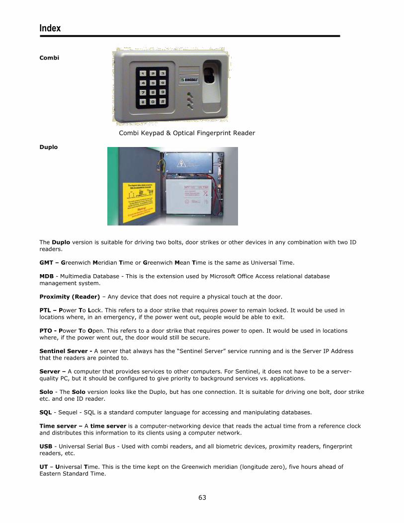
63
Index
Combi
Combi Keypad & Optical Fingerprint Reader
Duplo
The Duplo version is suitable for driving two bolts, door strikes or other devices in any combination with two ID
readers.
GMT – Greenwich Meridian Time or Greenwich Mean Time is the same as Universal Time.
MDB - Multimedia Database - This is the extension used by Microsoft Office Access relational database
management system.
Proximity (Reader) – Any device that does not require a physical touch at the door.
PTL – Power To Lock. This refers to a door strike that requires power to remain locked. It would be used in
locations where, in an emergency, if the power went out, people would be able to exit.
PTO - Power To Open. This refers to a door strike that requires power to open. It would be used in locations
where, if the power went out, the door would still be secure.
Sentinel Server - A server that always has the “Sentinel Server” service running and is the Server IP Address
that the readers are pointed to.
Server – A computer that provides services to other computers. For Sentinel, it does not have to be a server-
quality PC, but it should be configured to give priority to background services vs. applications.
Solo - The Solo version looks like the Duplo, but has one connection. It is suitable for driving one bolt, door strike
etc. and one ID reader.
SQL - Sequel - SQL is a standard computer language for accessing and manipulating databases.
Time server – A time server is a computer-networking device that reads the actual time from a reference clock
and distributes this information to its clients using a computer network.
USB - Universal Serial Bus - Used with combi readers, and all biometric devices, proximity readers, fingerprint
readers, etc.
UT – Universal Time. This is the time kept on the Greenwich meridian (longitude zero), five hours ahead of
Eastern Standard Time.

64
Ringdale Ltd
56 Victoria Road
Burgess Hill
West Sussex
RH15 9LR
United Kingdom
Freephone: 0800 214503
Tel: +44 (0) 1444 871349
Fax: +44 (0) 1444 870228
Ringdale GmbH
Cochemer Straße 12-14
D-68309 Mannheim
Germany
Freephone: 0800 - 8251880
Tel: +49 (0) 621 7186-0
Fax: +49 (0) 621 7186-20
Ringdale Inc
101 Halmar Cove
Georgetown, Texas 78628
USA
Freephone: 888 288 9080
Tel: +1 512 288 9080
Fax: +1 512 288 7210
Website: http://www.ringdale.com