sentry barrier™ - csppacific.co.nz
TRANSCRIPT
February 2021 | Page 1Ph 0800 655 200 or visit www.csp.co.nz
KEEPINGNZ SAFE
Roadside Workplace Roadwork Pedestrian Seeing Environment Telecoms
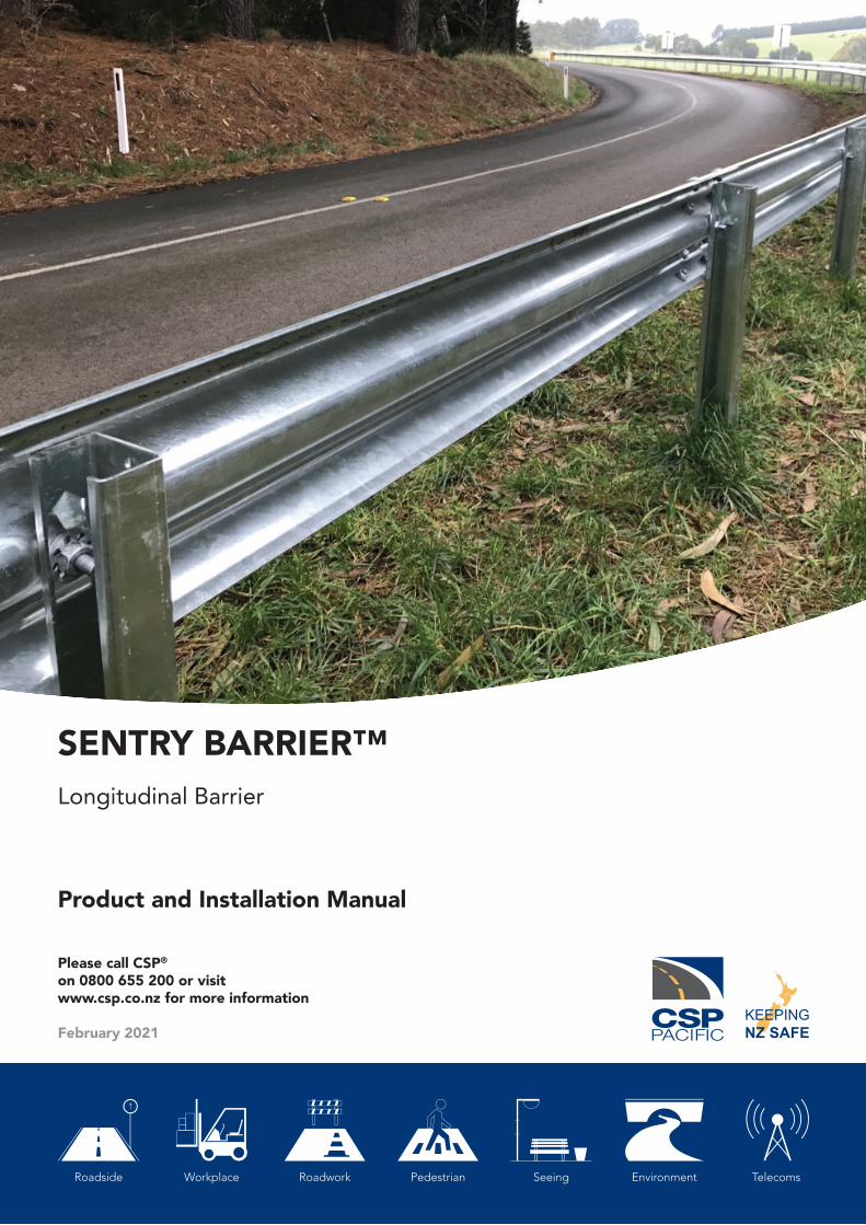
SENTRY BARRIER™Longitudinal Barrier
Product and Installation Manual
Please call CSP® on 0800 655 200 or visitwww.csp.co.nz for more information
February 2021KEEPINGNZ SAFE

February 2021 | Page 2Ph 0800 655 200 or visit www.csp.co.nz
Product & Installation Manual: Sentry Barrier™
KEEPINGNZ SAFE
Table of contents
Introduction
System Overview
Limitations and Warnings
Training
Health and Safety
Before Installation
Safety statements
General Safety
Sentry Barrier™ Safety Statements
Limited Warranty
System Design and Design Considerations
Kerbs
Slopes
Batter Hinge Proximity
Weak Soil Installations
Posts on Base Plates
Horizontal and Vertical Curves
Undulating Ground Conditions
Clear Zone / Hazard Free Zone
Terminal Ends
Soil Condition
Length of Need
System Deflection
Transitions
Parts Identification
Bill of Materials
Installation
Getting Started
4
4
5
5
6
6
6
6
6
7
8
8
8
8
9
9
10
10
11
11
12
12
13
13
14
15
16
16
February 2021 | Page 3Ph 0800 655 200 or visit www.csp.co.nz
Product & Installation Manual: Sentry Barrier™
KEEPINGNZ SAFE
Preparation
Soil Conditions
Tools Required
Installation Tolerances
Installation Instructions
Site Preparation
Post Orientation with traffic flow direction
Post driver machine - Impact head
Construction of Terminal End or Crash Cushion
Installation Procedure (Posts and W-Beam)
Inspection and Maintenance Frequency
Maintenance requirement for repair after a Bushfire
Installation Checklist for the Sentry Barrier™
Frequently Asked Questions
Appendices
Appendix A – Sentry Barrier™
Appendix B – Sentry Barrier™ Post
Appendix C – Sentry Barrier™ Washer
Appendix D – Installation Tolerance (Lateral)
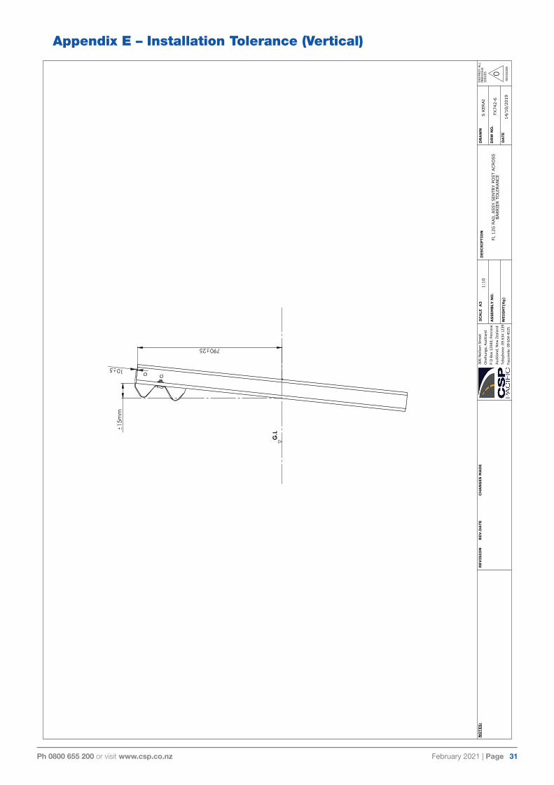
Appendix E – Installation Tolerance (Vertical)
Appendix F – Sentry Barrier™ Transition to MAX-Tension™ End Terminal
Appendix G – Sentry Barrier™ Bolt Down Assembly
Appendix H - Sentry Barrier™ to Suit 2H:1V B. Slope & Weak Soil
Appendix I – Acceptable Post Deformation Measures & Tolerances
Test 1: Nut Pass-through
Test 2: Washer Fitment
Test 3: Post deformation bending and cracking tolerance
16
16
17
18
19
19
19
19
20
20
23
23
24
25
26
27
28
29
30
31
32
33
34
35
35
35
35
CSP® may make changes to this Product Manual from time to time. Please check the CSP®
website prior to using this Product Manual to ensure that you have the latest version.
February 2021 | Page 4Ph 0800 655 200 or visit www.csp.co.nz
Product & Installation Manual: Sentry Barrier™
KEEPINGNZ SAFE
IntroductionThe Sentry Barrier™ is a roadside W-Beam guardrail system suitable for containing, redirecting and shielding vehicles from roadside obstacles. The barrier has been designed and tested to meet the evaluation criteria of MASH Test Level 3 (TL-3) for a longitudinal barrier. This is the current state of the art performance criteria, exceeding the requirements of NCHRP 350 TL-3.
The Sentry Barrier™ has an initial installation height of 800 mm to the top of the rail, providing the system with the ability to withstand numerous road surface overlays without the need to relevel of lifting of the barrier. The Sentry Barrier™ can be installed with an approved energy absorbing terminal end on the approach end, however it is recommended that an approved tangential or flared MAX-Tension™ End Terminal be used for optimal performance.
The rounded edges to the Sentry Barrier™ Post and closed shape on the approach direction provide increased protection for vulnerable road users. The compact Sentry Barrier™ posts are easy to drive into all soil types and provide increased resistance to rotation in the soil when impacted. Unlike other systems on the market, any damage caused to the top of the posts or to the rail mounting points during installation will not affect the performance of the system.
The connection system between the rail and posts is formed using conventional fasteners providing it with the greatest tolerance of any system on the market. If the connection is damaged in any way it can be easily replaced without replacing the posts allowing for simpler installations and repairs. The Sentry Barrier™ is installed quickly using conventional installation tools and equipment.
System Overview
The Sentry Barrier™ is designed to provide acceptable structural adequacy, minimal occupant risk and safe vehicle trajectory as required by the latest in safety standards, AASHTO MASH 09 TL-3. This standard requires the system to be independently evaluated with full scaling testing using 1,100 kg and 2,270 kg vehicles traveling at speeds of 100 km/hr and impacting the system at an angle of 25 degrees. The requirements of MASH 09 TL-3 are so stringent that the system is required to absorb more energy during the impact than the out-dated NCHRP 350 standard TL-4.
When impacted by an errant vehicle, the Sentry Barrier™ will redirect the vehicle along the face of the barrier system, bringing it to a controlled stop. The system has been developed to produce no debris during an impact, with all posts designed to remain firmly located in the soil and the connection details to remain attached to the rail. Repair of the system is completed by removing and replacing any bent or damaged W-Beam and posts impacted accordingly. Any posts with damaged connections can be repaired by replacing the connection hardware only, reducing the need to remove posts and repair damaged ground.
Key specifications for the Sentry Barrier™ are:
System width 201 mm
Height to top of rail 800 mm
Height to top of post 790 mm
Post weight 13.7 kg
Post length 1.64 m
Post spacing 1.905 m
MASH TL3.10 dynamic deflection 1.02 m
MASH TL3.11 dynamic deflection 1.59 m
February 2021 | Page 5Ph 0800 655 200 or visit www.csp.co.nz
Product & Installation Manual: Sentry Barrier™
KEEPINGNZ SAFE
The minimum Length of Need (LON) of the Sentry Barrier™ is dependent on the posted speed limit. Please refer to Roading Controlling Authority approval letters for local minimum length requirements. However a minimum length of need for a two-way road with a posted speed limit of 100 km/hr with a clear zone of approaching traffic is recommend as 30 m, excluding terminal ends.
The Sentry Barrier™ system’s rails and posts are manufactured from hot-rolled steel flat products in accordance with AS/NZS 1594 and hot-dip galvanised in accordance with AS/NZS 4680 with an average minimum coating thickness of 35 microns. All galvanising is undertaken after fabrication is completed to ensure no surfaces are left untreated.
The Sentry Barrier™ has been designed for strength and resilience. Additional testing was completed to show that the barrier can withstand a second impact when already damaged. With no repairs completed to the barrier after a first test, it successfully resisted a direct impact to the damaged region by a 1500 kg vehicle travelling at a nominal 70 km/h and an impact angle of 25 degrees. The vehicle was smoothly redirected with no additional damage caused to the barrier.
Limitations and WarningsThe Sentry Barrier™ forms part of an approved roadside protection system and it must be installed in conjunction with an approved terminal end system on both the approach and trailing ends. When installed in accordance with the manufacturer’s instruction the barrier system allows an impacting vehicle to be re-directed in a safe and predictable manner under the MASH impact conditions.
Vehicle impacts that vary from the MASH impact conditions for longitudinal barriers may result
in significantly different outcomes from those obtained in the experimental testing and may not meet the MASH evaluation criteria.
The selection and placement of the Sentry Barrier must be in accordance with the Roading Controlling Authority’s guidelines and the details shown in the construction drawings. Installation must be within strict accordance with the installation instructions for the product. Alternative installation techniques will be required if the soil conditions on site do not meet the minimum requirements stated in this manual.
Training All Installers must undergo formal training on the installation of the Sentry Barrier™. This includes the correct identification of each Sentry Barrier™ components and installing it as per the product specification and Installation Manual.
By the end of the training, installers will be able to identify each component of the Sentry Barrier™ and have the knowledge to safely install the barrier as per the Installation Manual and Specifications required.
The training will cover and include the correct Personal Protective Equipment (PPE) required to be worn during installation and maintenance. Additionally by the end of the training, workers will know the correct methods required to handle and install all components of the Sentry Barrier™.

February 2021 | Page 6Ph 0800 655 200 or visit www.csp.co.nz
Product & Installation Manual: Sentry Barrier™
KEEPINGNZ SAFE
Health and Safety Installers should comply with all necessary health and safety legislation in the local jurisdiction, including all safe work and lifting practices.
All appropriate traffic safety precautions must be adopted. All workers must wear the required safety clothing, including but not limited to, high visibility vests, steel capped footwear, gloves and protective glasses etc.
Before undertaking any earth works, including drilling or driving of posts, always check with the appropriate service providers that the area is clear of underground services
All installers must be well clear of machinery when posts are being driven.
Before InstallationDesign, selection and placement of the Sentry Barrier™ shall be in accordance with the local Road Controlling Authority’s guidelines and as per the details shown in the construction drawings. Installation shall be in accordance with the installation instructions supplied for this product.
The Sentry Barrier™ is an engineered safety device. Before starting installation ensure familiarity with the makeup of the system.
Note: Soil conditions may require a local geotechnical engineer to confirm the soil condition on site met the required condition described in the manual.
Safety statementsGeneral Safety
> All required traffic safety precautions should be complied with. All workers should wear required safety clothing (examples, but not limited to, include: high visibility vests, steel capped footwear, gloves etc).
> Only authorised trained personnel should operate any machinery. Where overhead machinery is used, care must be taken to avoid any overhead hazards.
> Before drilling or excavation always ensure that the area is clear of underground services. The appropriate service providers may need to be contacted.
Sentry Barrier Safety Statements
> All installers must be a safe distance from all drilling or excavating machinery operating.
> The components are not heavy enough to require specialised lifting equipment, but due to the dimensions and bulky nature, care should be taken when lifting the larger components into position.
> Avoid placing hands or fingers in and around moving machine parts when components are being lifted and manoeuvred into place.

February 2021 | Page 7Ph 0800 655 200 or visit www.csp.co.nz
Product & Installation Manual: Sentry Barrier™
KEEPINGNZ SAFE
Limited WarrantyCSP Pacific (CSP) has tested the impact performance of its barrier systems and crash cushion systems, and other highway safety hardware under controlled conditions, however, CSP does not represent nor warrant that the results of those controlled conditions would necessarily avoid injury to persons or property.
TO THE MAXIMUM EXTENT PERMITTED BY LAW, CSP EXPRESSLY DISCLAIMS ANY WARRANTY OR LIABILITY FOR CLAIMS ARISING BY REASONS OF DEATH OR PERSONAL INJURY OR DAMAGE TO PROPERTY RESULTING FROM ANY IMPACT, COLLISION OR HARMFUL CONTACT WITH THE PRODUCTS OR NEARBY HAZARDS OR OBJECTS BY ANY VEHICLE, OBJECTS OR PERSONS.
CSP warrants that any product or component part manufactured by CSP will be free from defects in material or workmanship. CSP will replace free of cost any product or component part manufactured by CSP that contains such a defect.
TO THE MAXIMUM EXTENT PERMITTED BY LAW, CSP EXPRESSLY DISCLAIMS THE FOREGOING WARRANTY IS IN LIEU OF AND EXCLUDES ALL OTHER WARRANTIES NOT EXPRESSLY SET FORTH HEREIN, WHETHER EXPRESS OR IMPLIED BY OPERATION OF LAW OR OTHERWISE, INCLUDING BUT NOT LIMITED TO ANY IMPLIED WARRANTIES OF MERCHANTABILITY OR FITNESS FOR A PARTICULAR PURPOSE. CSP’S LIABILITY UNDER THIS WARRANTY IS EXPRESSLY LIMITED TO REPLACEMENT FREE OF COST OF PARTS SUPPLIED BY CSP ONLY (IN THE FORM AND UNDER THE TERMS ORIGINALLY SHIPPED), OR TO REPAIR OR TO MANUFACTURE BY CSP, PRODUCTS OR PARTS NOT COMPLYING WITH CSP
SPECIFICATIONS, OR, AT CSP’S ELECTION, TO THE REPAYMENT OF AN AMOUNT EQUAL TO THE PURCHASE PRICE OF SUCH PRODUCTS OR PARTS, WHETHER SUCH CLAIMS ARE FOR BREACH OF WARRANTY OR NEGLIGENCE. CSP SHALL NOT BE LIABLE FOR ANY INCIDENTAL, CONSEQUENTIAL OR SPECIAL LOSSES, DAMAGES OR EXPENSES OF ANY KIND, INCLUDING, WITHOUT LIMITATION, ANY SUCH LOSSES, DAMAGES OR EXPENSES ARISING DIRECTLY OR INDIRECTLY FROM THE SALE, HANDLING OR USE OF THE PRODUCTS FROM ANY OTHER CAUSE RELATING THERETO, OR FROM PERSONAL INJURY OR LOSS OF PROFIT.
Any claim by the Buyer with reference to Products sold hereunder for any cause shall be deemed waived by the Buyer unless CSP is notified in writing, in the case of defects apparent on visual inspection, within ninety (90) days from the delivery date, or, in the case of defects not apparent on visual inspection, within twelve (12) months from the said delivery date. Products claimed to be defective may be returned prepaid to CSP’s plant for inspection in accordance with return shipping instructions that CSP shall furnish to the Buyer forthwith upon receipt of the Buyer’s notice of claim. If the claim is established, CSP will reimburse that Buyer for all carriage costs incurred hereunder.
The forgoing warranty benefits shall not apply to (i) any Products that have been subject to improper storage, accident, misuse or unauthorised alterations, or that have not been installed, operated and maintained in accordance with approved procedures and (ii) any components manufactured by the Buyer.
The customer acknowledges that it has acquired the Goods for the purposes of a business and that the Consumer Guarantees Act 1993 will not apply to the supply of the Goods by CSP to it.

February 2021 | Page 8Ph 0800 655 200 or visit www.csp.co.nz
Product & Installation Manual: Sentry Barrier™
KEEPINGNZ SAFE
System Design and Design ConsiderationsKerbs
As with all road side safety hardware, the Sentry Barrier™ has been designed and tested so that the centre of gravity of the impacting vehicle is at a constant height in relation to the system. For this reason, it is preferred that kerbs or channels are not in front or directly behind the Sentry Barrier™ as they may result in altering the height of the vehicle at impact.
If interaction with a kerb cannot be avoided consult the local Road Controlling Authority guidelines regarding allowable kerb heights, kerb shapes, and barrier offset distance.
Slopes
The Sentry Barrier™ can be installed on ground with a maximum cross fall of 6H:1V. For steeper slopes it is recommended that the system is installed no closer than 300 mm to the batter hinge point of the slope. If installations with less clearance are required, please contact CSP®.
Batter Hinge Proximity Sentry Barrier™ has been R & D crash tested to MASH TL-3 when installed with nil offset to a batter hinge point with a batter gradient of 2H:1V. For a TL-3 containment level, the minimum proximity to the hinge point shall be where the back edge of the Sentry Post meets the Batter Hinge Point as shown in the figure below.
As the proximity to the batter slope reduces the soil support to the post, a 2100 mm long Sentry Post is required. Installations in close proximity to a batter hinge point should be considered within the requirements of the Road Controlling Authority Extended Design Domain requirements.
February 2021 | Page 9Ph 0800 655 200 or visit www.csp.co.nz
Product & Installation Manual: Sentry Barrier™
KEEPINGNZ SAFE
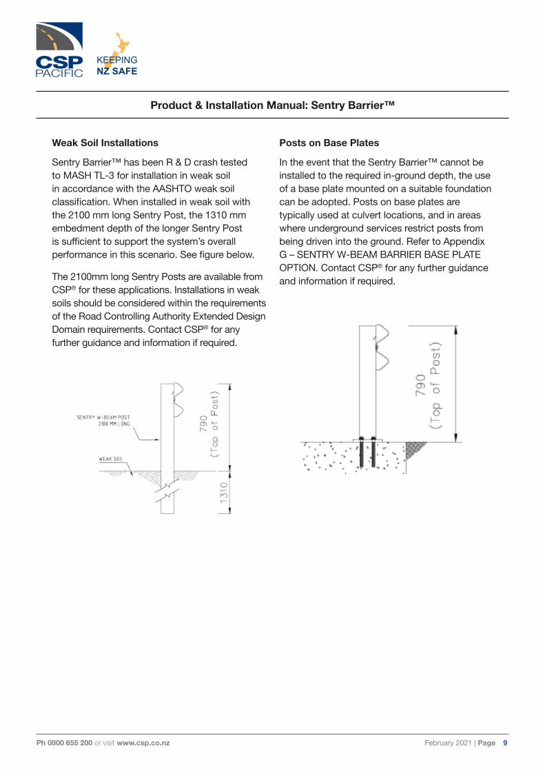
Weak Soil Installations
Sentry Barrier™ has been R & D crash tested to MASH TL-3 for installation in weak soil in accordance with the AASHTO weak soil classification. When installed in weak soil with the 2100 mm long Sentry Post, the 1310 mm embedment depth of the longer Sentry Post is sufficient to support the system’s overall performance in this scenario. See figure below.
The 2100mm long Sentry Posts are available from CSP® for these applications. Installations in weak soils should be considered within the requirements of the Road Controlling Authority Extended Design Domain requirements. Contact CSP® for any further guidance and information if required.
Posts on Base Plates
In the event that the Sentry Barrier™ cannot be installed to the required in-ground depth, the use of a base plate mounted on a suitable foundation can be adopted. Posts on base plates are typically used at culvert locations, and in areas where underground services restrict posts from being driven into the ground. Refer to Appendix G – SENTRY W-BEAM BARRIER BASE PLATE OPTION. Contact CSP® for any further guidance and information if required.
February 2021 | Page 10Ph 0800 655 200 or visit www.csp.co.nz
Product & Installation Manual: Sentry Barrier™
KEEPINGNZ SAFE
Horizontal and Vertical Curves
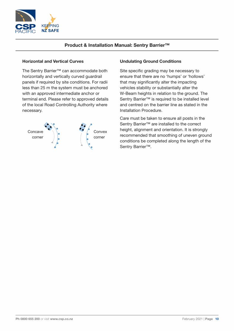
The Sentry Barrier™ can accommodate both horizontally and vertically curved guardrail panels if required by site conditions. For radii less than 25 m the system must be anchored with an approved intermediate anchor or terminal end. Please refer to approved details of the local Road Controlling Authority where necessary.
Undulating Ground Conditions
Site specific grading may be necessary to ensure that there are no ‘humps’ or ‘hollows’ that may significantly alter the impacting vehicles stability or substantially alter the W-Beam heights in relation to the ground. The Sentry Barrier™ is required to be installed level and centred on the barrier line as stated in the Installation Procedure.
Care must be taken to ensure all posts in the Sentry Barrier™ are installed to the correct height, alignment and orientation. It is strongly recommended that smoothing of uneven ground conditions be completed along the length of the Sentry Barrier™.
Concavecorner
Convexcorner

February 2021 | Page 11Ph 0800 655 200 or visit www.csp.co.nz
Product & Installation Manual: Sentry Barrier™
KEEPINGNZ SAFE
Clear Zone / Hazard Free Zone
Clear Zones are areas adjacent to traffic lanes that provide errant vehicles the opportunity to slow down or recover. The clear zone must be kept clear from roadside features that could be hazardous to an errant vehicles, such as but not limited to trees, poles and culverts. Although it is desirable to maximize the available clear zone, please refer to your local Road Controlling Authority for confirmation of the minimum width requirements.
Terminal Ends
The Sentry Barrier™ is designed to be compatible with a range of w-beam guardrail terminals ends or crash cushions available in the public domain. It is recommended that MAX-Tension™ End Terminal be used with the Sentry Barrier for optimal performance. Refer to Appendix F – Sentry Barrier™ TRANSITION TO MAX-Tension™ End Terminal.
The purpose of the W-Beam guardrail terminals ends or crash cushions is to provide a soft impact and to prevent the end rail from spearing or impacting the errant vehicle. The terminals ends and crash cushions also provide tensile and deflection strength necessary to ensure the errant vehicle is redirected for the length-of-need required.
> Care must be taken to ensure the correct post spacing is ALWAYS used during the installation.
> Care must be taken to ensure the posts are orientated correctly during installation and to ensure all W-Beams bolts are inserted and tightened accordingly.
> Care must be taken to ensure the line posts are installed at the correct height.
February 2021 | Page 12Ph 0800 655 200 or visit www.csp.co.nz
Product & Installation Manual: Sentry Barrier™
KEEPINGNZ SAFE
Soil Condition
The Sentry Barrier™ is a soil-mounted system driven directly into the soil. Sentry Barrier™ posts should be installed in soil conditions that meet AASHTO Grade B standard and requirements set out by AS/NZS 3845:1999 and TNZ Specification M/4 2006.
Soil conditions that do not meet these requirements will require alternative installation. Contact CSP® for details.
It is strongly recommended that soil tests be completed at the location where the Sentry Barrier is to be installed.
Note: All technical information required to assist in designing a site specific foundation is available from CSP®.
IF SOIL CONDITIONS ON SITE DO NOT MEET OR EXCEED THE REQUIRED STRENGTH, SITE SPECIFIC CONDITIONS, REFER TO A LOCAL GEOTECHNICAL ENGINEER FOR FURTHER ADVICE.
Length of Need
The minimum Length of Need (LoN) of the Sentry Barrier™ is dependent on the specific hazard being protected and the posted speed limit. Please refer to Road Controlling Authority approval letters for local minimum length requirements.
The minimum length of need for a two-way road with a posted speed limit of 100 km/hr with a clear zone of approaching traffic is recommend as 30 m plus the length of the terminal end regions on either end of the barrier system. We recommend Installers contact their local Roading Control Authority for further information or guidance.
Note: As per the LoN design section of the Roading Control Authority’s guidelines, care must be taken when calculating the actual length of a barrier required verses the theoretical length of need.
February 2021 | Page 13Ph 0800 655 200 or visit www.csp.co.nz
Product & Installation Manual: Sentry Barrier™
KEEPINGNZ SAFE
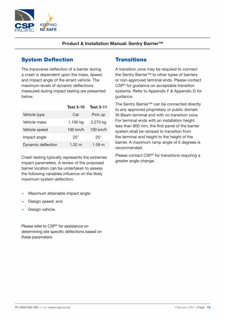
System Deflection
The transverse deflection of a barrier during a crash is dependent upon the mass, speed, and impact angle of the errant vehicle. The maximum levels of dynamic deflections measured during impact testing are presented below.
Crash testing typically represents the extremes impact parameters. A review of the proposed barrier location can be undertaken to assess the following variables influence on the likely maximum system deflection;
> Maximum attainable impact angle;
> Design speed; and
> Design vehicle.
Please refer to CSP® for assistance on determining site specific deflections based on these parameters.
Transitions
A transition zone may be required to connect the Sentry Barrier™ to other types of barriers or non-approved terminal ends. Please contact CSP® for guidance on acceptable transition systems. Refer to Appendix F & Appendix G for guidance.
The Sentry Barrier™ can be connected directly to any approved proprietary or public domain W-Beam terminal end with no transition zone. For terminal ends with an installation height less than 800 mm, the first panel of the barrier system shall be ramped to transition from the terminal end height to the height of the barrier. A maximum ramp angle of 5 degrees is recommended.
Please contact CSP® for transitions requiring a greater angle change.
Test 3-10 Test 3-11
Vehicle type Car Pick up
Vehicle mass 1,100 kg 2,270 kg
Vehicle speed 100 km/h 100 km/h
Impact angle 25° 25°
Dynamic deflection 1.02 m 1.59 m

February 2021 | Page 14Ph 0800 655 200 or visit www.csp.co.nz
Product & Installation Manual: Sentry Barrier™
KEEPINGNZ SAFE
Parts Identification
ALL STEEL COMPONENTS USED IN THE SENTRY BARRIER™ ARE HOT DIPPED GALVANISED IN ACCORDANCE WITH AS/NZS 4680
Sentry Barrier™ Post (3 views)
Sentry Barrier™Bolt, Washer & Nut
W-Beam Splice, Bolt & Nut
February 2021 | Page 15Ph 0800 655 200 or visit www.csp.co.nz
Product & Installation Manual: Sentry Barrier™
KEEPINGNZ SAFE
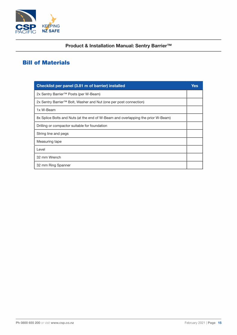
Bill of Materials
Checklist per panel (3.81 m of barrier) installed Yes
2x Sentry Barrier™ Posts (per W-Beam)
2x Sentry Barrier™ Bolt, Washer and Nut (one per post connection)
1x W-Beam
8x Splice Bolts and Nuts (at the end of W-Beam and overlapping the prior W-Beam)
Drilling or compactor suitable for foundation
String line and pegs
Measuring tape
Level
32 mm Wrench
32 mm Ring Spanner

February 2021 | Page 16Ph 0800 655 200 or visit www.csp.co.nz
Product & Installation Manual: Sentry Barrier™
KEEPINGNZ SAFE
InstallationGetting Started
The Sentry Barrier™ is a W-Beam barrier designed to run the length of need required and is attached to a compatible terminal end or crash cushion. The minimum Length of Need (LoN) allowed is dependent on the post speed limit. For a 100 km/hr zone a minimum LoN of 30 metres is recommended, excluding the proposed terminal end or crash cushion.
Preparation
Before installing an Sentry Barrier™, ensure that all components required for the system are on site and have been identified. The Sentry Barrier™ is an engineered safety device. Before starting installation ensure familiarity with the makeup of the system. Refer to the Bill of Materials and Parts Identification sections in this manual for more information.
Ensure that the area where the Sentry Barrier™ is to be installed is sufficiently flat so that the posts and W-Beam can be installed within the allowable tolerance and aligned to the terminal ends or crash cushions. Minor site grading may be required.
Soil Conditions
The Sentry Barrier™ has been designed to withstand a constant static load, thermal loading, and dynamic impact load that can be applied from the impact of an errant vehicle. To perform, the Sentry Barrier™ must be attached to either a semi rigid or rigid terminal end or crash cushion to provide the necessary safety benefits. It is recommended that the soil tests are carried out at the location the Sentry Barrier™ prior to being installed.
IF SOIL CONDITIONS ON SITE DO NOT MEET OR EXCEED THE REQUIRED STRENGTH DETAILED IN THIS MANUAL, SITE SPECIFIC FOUNDATIONS MUST BE DESIGNED BY A LOCAL GEOTECHNICAL ENGINEER.
February 2021 | Page 17Ph 0800 655 200 or visit www.csp.co.nz
Product & Installation Manual: Sentry Barrier™
KEEPINGNZ SAFE
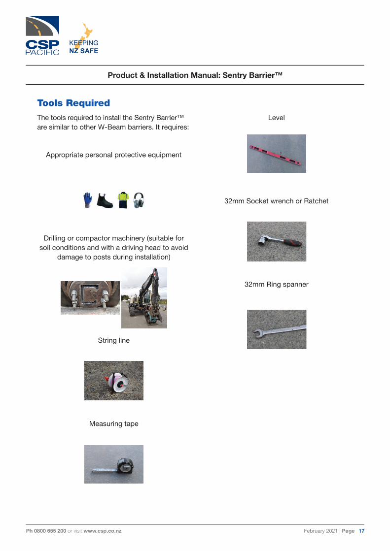
Tools RequiredThe tools required to install the Sentry Barrier™ are similar to other W-Beam barriers. It requires:
Appropriate personal protective equipment
Drilling or compactor machinery (suitable for soil conditions and with a driving head to avoid
damage to posts during installation)
String line
Measuring tape
Level
32mm Socket wrench or Ratchet
32mm Ring spanner

February 2021 | Page 18Ph 0800 655 200 or visit www.csp.co.nz
Product & Installation Manual: Sentry Barrier™
KEEPINGNZ SAFE
Installation TolerancesThe Sentry Barrier™ is an engineered safety device. To obtain optimal performance is it important to install all components of the system to within the allowable tolerances stated below (also in Appendix D and Appendix E). Particular care must be taken to ensure;
> Suitable horizontal alignment and verticality of the line posts.
> Consistency in the vertical height of the line posts.
> Orientation and height of the terminal end or crash cushion.
Sentry Barrier™ has to be installed at 790 mm
to the top of the post. A vertical height tolerance of ±25 mm is acceptable for Sentry Barrier™ post. The top of the W-Beam is to be positioned 10 mm above the top of the Sentry Barrier™ post with a tolerance of ±5 mm. The Sentry Barrier™ Post laterally is constrained to ±15 mm tolerance. It is of upmost importance for these tolerances to be adhered to in order to ensure safe function of the Sentry Barrier™.

February 2021 | Page 19Ph 0800 655 200 or visit www.csp.co.nz
Product & Installation Manual: Sentry Barrier™
KEEPINGNZ SAFE
Installation InstructionsBefore installing the Sentry Barrier™, ensure that all components required for the system are on site and have been identified. The Sentry Barrier™ is an engineered safety device made up of relatively small number of parts. Please ensure familiarity with the makeup of the system and the installation process prior to commencing. If required, refer to the Bill of Materials and Parts Identification sections in this manual for more information.
Site Preparation
It is preferred that the Sentry Barrier™ be installed on flat, level ground and tethered to an approved terminal end or crash cushion. The positioning of the Sentry Barrier™ commences from the last post connected to the terminal end or crash cushion, working upstream to the prior terminal end or crash cushion. It is recommended that a string line be used to obtain the correct orientation and placement of the posts and are aligned to the terminal end or crash cushions.
Post Orientation with traffic flow direction
Ensure posts are correctly orientated in relation to traffic flow direction by positioning the closed side of the post towards oncoming traffic. Refer to below.
BEFORE DRILLING OR EXCAVATION ALWAYS ENSURE THAT THE AREA IS CLEAR OF UNDERGROUND SERVICES.
Post driver machine - Impact head
Ensure a suitable post driver impact head that has been designed to drive Sentry posts is used in order to avoid damage to posts during installation. Below are examples of suitably designed impact heads. Contact CSP® for assistance if required.
In cases where very hard ground conditions are encountered, minor deformation may occur near the top of the post. If it occurs, please refer to Appendix I – ACCEPTABLE POST DEFORMATION MEASURES & TOLERANCES, to determine if the deformation is acceptable for the continuation of installation.
February 2021 | Page 20Ph 0800 655 200 or visit www.csp.co.nz
Product & Installation Manual: Sentry Barrier™
KEEPINGNZ SAFE
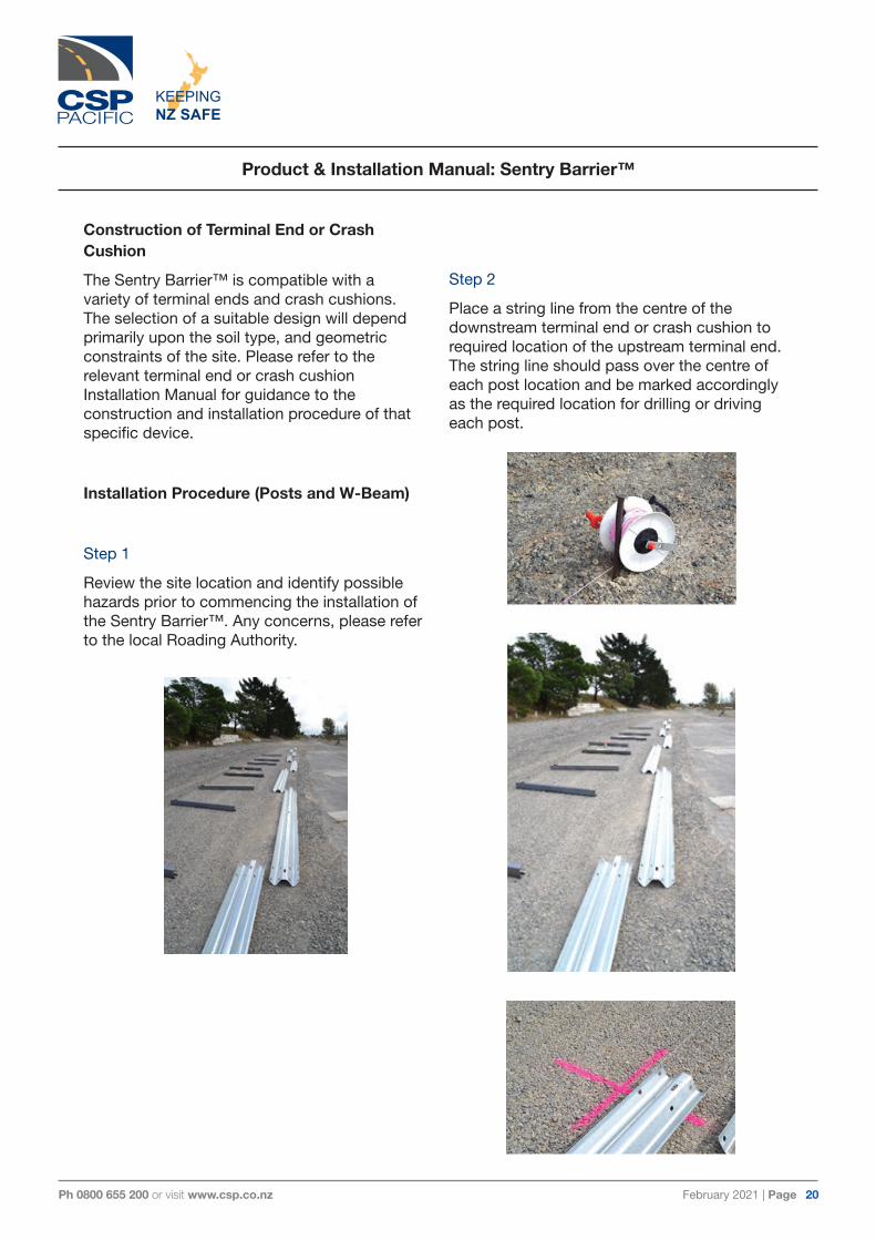
Construction of Terminal End or Crash Cushion
The Sentry Barrier™ is compatible with a variety of terminal ends and crash cushions. The selection of a suitable design will depend primarily upon the soil type, and geometric constraints of the site. Please refer to the relevant terminal end or crash cushion Installation Manual for guidance to the construction and installation procedure of that specific device.
Installation Procedure (Posts and W-Beam)
Step 1
Review the site location and identify possible hazards prior to commencing the installation of the Sentry Barrier™. Any concerns, please refer to the local Roading Authority.
Step 2
Place a string line from the centre of the downstream terminal end or crash cushion to required location of the upstream terminal end. The string line should pass over the centre of each post location and be marked accordingly as the required location for drilling or driving each post.

February 2021 | Page 21Ph 0800 655 200 or visit www.csp.co.nz
Product & Installation Manual: Sentry Barrier™
KEEPINGNZ SAFE
Step 3
Identify the correct orientation of the post (refer to Appendix A - Sentry Barrier™) and drive post to the predetermined depth of 850 mm (790 mm protruding above ground) as stipulated in Appendix A - Sentry Barrier™. The post must be vertically aligned and within the tolerance level stated in the Installation Tolerance section (page 16). The driving of the post should not incur any damage to the post. If a post is damaged it must be inspected and removed if considered that the damage will affect the performance.
Step 4
Supporting the W-Beam in the desired location, install the Sentry Barrier™ Bolt, Washer and Nut. Once supported, the 8 Splice Bolts and Nuts can be inserted into the W-Beam splice joint. It is vital that each W-Beam must overlap the prior W-Beam positioned downstream. Failure to correctly overlap the W-Beam may cause snagging, poor barrier performance or risk injury or death to the driver of the errant vehicle. Snug tighten all bolts once installed.
Splice joint location

February 2021 | Page 22Ph 0800 655 200 or visit www.csp.co.nz
Product & Installation Manual: Sentry Barrier™
KEEPINGNZ SAFE
Step 5
Continue working along the barrier from the first installed W-Beam to the terminal end or crash cushion positioned at the other end of the barrier system. Once the barrier is installed a detailed visual inspection should be completed to ensure all components are correctly installed. All bolts should be confirmed to be installed snug tight.
W-Beam Ends
Intermediary Post (middle section)
February 2021 | Page 23Ph 0800 655 200 or visit www.csp.co.nz
Product & Installation Manual: Sentry Barrier™
KEEPINGNZ SAFE
Inspection and Maintenance Frequency
The Sentry Barrier™ is maintenance free. However it is recommended that all W-Beam barrier systems are checked after being impacted to ensure that the appropriate strength is maintained. Refer to the installation procedure in this manual for more information.
Maintenance requirement for repair after a fire
Following a severe fire a detailed inspection of the Sentry Barrier™ should be undertaken. If heat damage is noted, it is recommended the W-Beam and posts are replaced immediately.
A detailed inspection should also be completed on the post footings and the transition between the W-Beam barrier and terminal end or crash cushion. Any concerns, please refer to the Sentry Barrier™ Installation Manual or contact CSP® for recommendations or inspections of the Sentry Barrier™ itself.

February 2021 | Page 24Ph 0800 655 200 or visit www.csp.co.nz
Product & Installation Manual: Sentry Barrier™
KEEPINGNZ SAFE
Installation Checklist
Contact CSP® for more information on this or other road safety products.
Job Number:
Location:
Client/Asset Owner:
Principal Contractor:
Installer:
Installed by: Date
Inspected by: Date
Item Y N
Ensure the posts are orientated in the correct direction and consistent with the terminal ends or crash cushions.
The height of the finished rail should be 800 mm (±25 mm) above the finished ground level.
The height to the top of the posts should be 790 mm (±25 mm) above finished ground level. It should be ensured that the post DOES NOT protrude above the W-Beam.
The posts are free from damage.
The correct Sentry Barrier™ Washer is installed and seated correctly in the back of the post.
All bolts are tightened snug.
The W-Beam must be level and aligned to the terminal end or crash cushion in accordance with transition drawings.
Refer to Appendix F of the Product and Installation Manual for guidance.
Ensure posts are free of debris prior to installing the W-Beam.
The top edge of the W-Beam must align, both vertically and horizontally, between the Sentry Barrier™ and the nominated terminal end in accordance with transition drawings.
Refer to Appendix F of the Product and Installation Manual.
February 2021 | Page 25Ph 0800 655 200 or visit www.csp.co.nz
Product & Installation Manual: Sentry Barrier™
KEEPINGNZ SAFE
Frequently Asked Questions
1. What type of equipment is required to install the Sentry Barrier™? Standard tools required include a wrench, measuring tape, string line and machinery suitable for drilling or compacting the post into soil.
2. Does your company provide spare parts? What is the lead-time for supply? It is important to fix a damaged W-Beam barrier as soon possible because it most probably won’t perform as designed when damaged. For this reason it is recommended that spares are held by Maintenance Contractors. The lead time for parts will generally be next day delivery or collection from one of our distribution centres.
3. On average, how long does it take to install the Sentry Barrier™? Depending on circumstances at the site, installation and assembly of the system should take a three person crew less than 15 mins per W-Beam panel (4.0 m length) when using automatic post driving equipment. Installation time will vary depending on ground conditions when hand digging and re-compacting posts.
4. What about vandalism, can the Sentry Barrier™ be damaged easily? No, once the system has been fully installed it becomes a rigid system unlikely to be damaged or weaken the performance of the system.
5. How easily can the Sentry Barrier™ be restored after impact? Sentry Barrier™ is easily repaired following an impact. Damaged posts can be removed using a crow bar and new posts installed before replacement W-Beams and splice bolts are positioned. The connection detail used between the post and the rail of the Sentry Barrier™ is designed to limit damage to the post outside of the immediate zone of impact. When the connection is damaged, the washer detail can be easily replaced without needing to replace the post.
6. What maintenance does the Sentry Barrier™ require? The Sentry Barrier™ is maintenance free. However it is recommended that all W-Beam barrier systems are checked after impacts to ensure that the integrity of the barrier is maintained.
February 2021 | Page 26Ph 0800 655 200 or visit www.csp.co.nz
Product & Installation Manual: Sentry Barrier™
KEEPINGNZ SAFE
APPENDICES

February 2021 | Page 27Ph 0800 655 200 or visit www.csp.co.nz
Appendix A – Sentry Barrier™
CL
1905
C
L19
05
1650 (TOP OF RAIL)
CL
3810
790 (TOP OF POST)
800 TOP OF RAIL
850
A
A
A
G.L
2
11
ITEM
NO
.PA
RT N
O.
DESC
RIPT
ION
QTY
.W
EIG
HT E
A.
DWG
NO
.1
2082
790
FL P
OST
STL
SEN
TRY
1.64
m G
300
213
.74
FX74
2-1
220
8002
2FL
12G
381
0 G
alv
141
.42
FX33
320
8280
0SEN
BNW
MUS
HRO
OM
HEA
D B
OLT
& O
VER
SIZE
D N
UT M
16x5
0 2
0.12
FX74
2-2
420
8279
1FL
WA
SHER
SEN
TRY
58 O
.D x
2.5
mm
GA
LV2
0.04
FX74
2-3
520
8012
8BN
W S
PLIC
E BO
LT &
NUT
HT
M16
x32
80.
01FX
140
BB
SEC
TION
A-A
SCA
LE 1
: 5
SEC
TION
B-B
SCA
LE 1
: 2
3
4
5
2
1
DETA
IL A
SCA
LE 1
: 2
A3
DES
TRO
Y AL
LPR
EVIO
US
ISSU
ES
REV
ISIO
N
SC
ALE
DA
TE
DR
AW
N
DR
W N
O.
DES
CR
IPTI
ON
0
S K
ERAI
14/1
0/20
19
AS
SEM
BLY
NO
.
306
Nei
lson
Stre
etO
nehu
nga,
Auc
klan
dP
O B
ox 1
2949
, Pen
rose
Auck
land
, New
Zea
land
Tele
phon
e: 0
9 63
4 12
39Fa
csim
ile: 0
9 63
4 45
25
FL 1
2G R
AIL
ASSY
SEN
TRY
POST
2082
803S
EN
1:15
FX74
2
WEI
GH
T(K
g)69
.87
NO
TES
:R
EVIS
ION
REV
.DA
TEC
HA
NG
ES M
AD
E
February 2021 | Page 28Ph 0800 655 200 or visit www.csp.co.nz
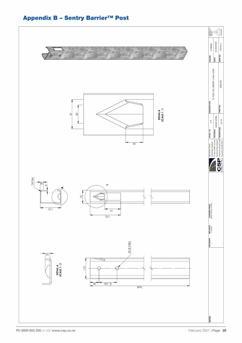
Appendix B – Sentry Barrier™ Post
72
170
77
B
24
41
20
DETA
IL B
SCA
LE 1
: 1
115
18
4 TYP
R4
1640
115
50 CL100
18 T
HRU
16
DETA
IL A
SCA
LE 1
: 2
A
A3
DES
TRO
Y AL
LPR
EVIO
US
ISSU
ES
REV
ISIO
N
SC
ALE
DA
TE
DR
AW
N
MA
TER
IAL
WEI
GH
T(K
g)D
RW
NO
.
DES
CR
IPTI
ON
1
S K
ERAI
31/0
8/20
20
PA
RT
NO
.FX
742-
1
306
Nei
lson
Stre
etO
nehu
nga,
Auc
klan
dP
O B
ox 1
2949
, Pen
rose
Auck
land
, New
Zea
land
Tele
phon
e: 0
9 63
4 12
39Fa
csim
ile: 0
9 63
4 45
2520
8279
013
.74
1:4
FL P
OST
STL
SEN
TRY
1.64
m G
300
1R
EVIS
ION
REV
.DA
TEC
HA
NG
ES M
AD
E31
/08/
20BE
ND
RA
DIU
S A
DD
EDN
OTE
S:
HA30
0 STE
EL

February 2021 | Page 29Ph 0800 655 200 or visit www.csp.co.nz
Appendix C – Sentry Barrier™ Washer
16.5
58
32
40
A
8 HO
LES
8 O
N
40 P
CD
8 HO
LES
5 O
N
32 P
CD
2.5
R2.5
R4
R2
DETA
IL A
SCA
LE 4
: 1
A3
DES
TRO
Y AL
LPR
EVIO
US
ISSU
ES
REV
ISIO
N
SC
ALE
DA
TE
DR
AW
N
MA
TER
IAL
WEI
GH
T(K
g)D
RW
NO
.
DES
CR
IPTI
ON
0
S K
ERAI
14/1
0/20
19
PA
RT
NO
.FX
742-
3
306
Nei
lson
Stre
etO
nehu
nga,
Auc
klan
dP
O B
ox 1
2949
, Pen
rose
Auck
land
, New
Zea
land
Tele
phon
e: 0
9 63
4 12
39Fa
csim
ile: 0
9 63
4 45
2520
8279
10.
04
2:1
FL W
ASH
ER S
ENTR
Y 58
O.D
X 2
.5m
m G
ALV
REV
ISIO
NR
EV.D
ATE
CH
AN
GES
MA
DE
NO
TES
:
GALV
AN
IZED
STE
EL

February 2021 | Page 30Ph 0800 655 200 or visit www.csp.co.nz
Appendix D – Installation Tolerance (Lateral)
15
mm
G.L
A3
DES
TRO
Y AL
LPR
EVIO
US
ISSU
ES
REV
ISIO
N
SC
ALE
DA
TE
DR
AW
N
DR
W N
O.
DES
CR
IPTI
ON
0
S K
ERAI
14/1
0/20
19
AS
SEM
BLY
NO
.
306
Nei
lson
Stre
etO
nehu
nga,
Auc
klan
dP
O B
ox 1
2949
, Pen
rose
Auck
land
, New
Zea
land
Tele
phon
e: 0
9 63
4 12
39Fa
csim
ile: 0
9 63
4 45
25
FL 1
2G R
AIL
ASSY
SEN
TRY
POST
ALO
NG
TH
E BARRIE
R T
OLE
RAN
CE
1:12
FX74
2-5
WEI
GH
T(K
g)
NO
TES
:R
EVIS
ION
REV
.DA
TEC
HA
NG
ES M
AD
E
February 2021 | Page 31Ph 0800 655 200 or visit www.csp.co.nz
Appendix E – Installation Tolerance (Vertical)
105
15
mm
79025
G.L
A3
DES
TRO
Y AL
LPR
EVIO
US
ISSU
ES
REV
ISIO
N
SC
ALE
DA
TE
DR
AW
N
DR
W N
O.
DES
CR
IPTI
ON
0
S K
ERAI
14/1
0/20
19
AS
SEM
BLY
NO
.
306
Nei
lson
Stre
etO
nehu
nga,
Auc
klan
dP
O B
ox 1
2949
, Pen
rose
Auck
land
, New
Zea
land
Tele
phon
e: 0
9 63
4 12
39Fa
csim
ile: 0
9 63
4 45
25
FL 1
2G R
AIL
ASSY
SEN
TRY
POST
ACRO
SS
BARRIE
R T
OLE
RAN
CE
1:10
FX74
2-6
WEI
GH
T(K
g)
NO
TES
:R
EVIS
ION
REV
.DA
TEC
HA
NG
ES M
AD
E

February 2021 | Page 32Ph 0800 655 200 or visit www.csp.co.nz
Appendix F – Sentry Barrier™ Transition to MAX-Tension™ End Terminal
306
Neils
on S
treet
,On
ehun
ga, A
uckla
ndPO
Box
12 94
9, Pe
nros
eAu
cklan
d, Ne
w Ze
aland
Telep
hone
09-6
34 12
39Fa
csim
ile 0
9-63
4 452
5ww
w.cs
ppac
ific.co
.nz

February 2021 | Page 33Ph 0800 655 200 or visit www.csp.co.nz
Appendix G - Sentry Barrier™ Bolt Down Assembly
CL
1905
C
L19
05
MIN
IMUM
LEN
GTH
OF
GRO
UND
BEA
M T
O B
E 20
m
800 (TOP OF THE RAIL)
790 (TOP OF POST)
A A
CC
G.L
ITEM
NO
.PA
RT N
O.
DESC
RIPT
ION
QTY
.W
EIG
HT E
A.
DWG
NO
.1
2082
851S
ENSL
SEN
TRY
BOLT
DO
WN
PO
ST 0
.774
m2
12.0
9FX
752-
12
2080
022
FL 1
2G 3
810
GA
LV1
41.3
8FX
333
2082
791
FL W
ASH
ER S
ENTR
Y 58
O.D
x 2
.5m
m G
ALV
20.
04FX
742-
34
2082
800S
ENBN
W M
USHR
OO
M H
EAD
BO
LT &
OV
ERSI
ZED
NUT
M16
x50
20.
12FX
742-
25
2080
128
BNW
SPL
ICE
BOLT
& N
UT H
T M
16x3
2 8
0.01
FX14
06
FTRM
20BN
W F
ULLY
THR
EAD
ED R
OD
M20
X230
8.8
GA
LV8
0.57
720
8012
4BN
W W
ASH
ER R
OUN
D M
20X3
9X3
GA
LV8
0.02
827
0050
7ABN
W E
NG
NUT
M20
GA
LV S
TRUC
TURA
L8
0.06
16
700
800 400
150
75
(CO
VER
) 7
5 (C
OV
ER)
BB
SEC
TION
A-A
SCA
LE 1
: 10
C L
4 X
HD20
2 x
HD16
R10@
300
c/c
30M
PA C
ON
CRE
TE
SEC
TION
B-B
SCA
LE 1
: 2
43
12
CL80
CL
155
4 x
22 T
HRU
200
250
SEC
TION
C-C
- BA
SEFL
AN
GE
SCA
LE 1
: 4
SEE
DRA
WIN
GFX
752-
3 FO
R SL
OT
CUT
DET
AIL
ISO
MET
RIC
VIE
WSC
ALE
1 :
20
1. F
IXIN
G B
OLT
S TO
BE
M20
GR
8.8
THRE
AD
ED R
OD
S FI
XED
WITH
HIL
TI RE
-500
EPO
XY.
2. M
INIM
UM F
IXIN
G B
OLT
EM
BED
MEN
T D
EPTH
: 1
70m
m3.
MIN
IMUM
CO
NC
RETE
SUB
STRA
TE T
HIC
KNES
S:
270m
m4.
REF
ER T
O N
ZTA
TEC
HNIC
AL
MEM
O T
M-0
12 F
OR
GRO
UND
BEA
M D
ETA
ILS.
A3
DES
TRO
Y AL
LPR
EVIO
US
ISSU
ES
REV
ISIO
N
SC
ALE
DA
TE
DR
AW
N
DR
W N
O.
DES
CR
IPTI
ON
1
S K
ERAI
5/11
/202
0
AS
SEM
BLY
NO
.
306
Nei
lson
Stre
etO
nehu
nga,
Auc
klan
dP
O B
ox 1
2949
, Pen
rose
Auck
land
, New
Zea
land
Tele
phon
e: 0
9 63
4 12
39Fa
csim
ile: 0
9 63
4 45
25
FL S
ENTR
Y BO
LT D
OW
N A
SSY
0.77
4m20
8283
0SEN
1:15
FX75
2
WEI
GH
T(K
g)69
.87
NO
TES
:1
REV
ISIO
NR
EV.D
ATE
CH
AN
GES
MA
DE
5/11
/202
0SL
OT
CUT
S A
DD
ED A
ROUN
D F
OO
T PL
ATE
HO
LES

February 2021 | Page 34Ph 0800 655 200 or visit www.csp.co.nz
Appendix H – Sentry Barrier™ to suit 2H:1V b.slope & weak soil
CL
1905
C
L19
05
CL
3810
2110 (TOP OF RAIL) 800 (TOP OF RAIL) 1310 (POST BELOW GROUND)
790 (TOP OF POST)
A A
A
G.L
ITEM
NO
.PA
RT N
O.
DESC
RIPT
ION
QTY
.W
EIG
HT E
A.
DWG
NO
.1
2082
793
FL P
OST
STL
SEN
TRY
2.1m
G30
02
17.6
3FX
753-
12
2080
022
FL 1
2G 3
810
GA
LV1
41.3
8FX
333
2082
800S
ENBN
W M
USHR
OO
M H
EAD
BO
LT &
OV
ERSI
ZED
NUT
M16
x50
20.
12FX
742-
24
2082
791
FL W
ASH
ER S
ENTR
Y 58
O.D
x 2
.5m
m G
ALV
20.
04FX
742-
35
2080
128
BNW
SPL
ICE
BOLT
& N
UT H
T M
16x3
2 8
0.01
FX14
0
2100 (POST LENGTH)
BB
SEC
TION
A-A
SCA
LE 1
: 5
SEC
TION
B-B
SCA
LE 1
: 2
3
41
2
DETA
IL A
SCA
LE 1
: 2
A3
DES
TRO
Y AL
LPR
EVIO
US
ISSU
ES
REV
ISIO
N
SC
ALE
DA
TE
DR
AW
N
DR
W N
O.
DES
CR
IPTI
ON
0
S K
ERAI
10/0
9/20
20
AS
SEM
BLY
NO
.
306
Nei
lson
Stre
etO
nehu
nga,
Auc
klan
dP
O B
ox 1
2949
, Pen
rose
Auck
land
, New
Zea
land
Tele
phon
e: 0
9 63
4 12
39Fa
csim
ile: 0
9 63
4 45
25
FL 1
2G R
AIL
ASSY
SEN
TRY
POST
SU
ITABLE
FO
R 2
H:1
V B
.SLO
PE &
WEA
K S
OIL
2082
837S
EN
1:15
FX75
3
WEI
GH
T(K
g)74
.72
NO
TES
:R
EVIS
ION
REV
.DA
TEC
HA
NG
ES M
AD
E

February 2021 | Page 35Ph 0800 655 200 or visit www.csp.co.nz
Test 1: Nut Pass-through
Ensure the nut can adequately pass through the slot at all locations along the slots length. This can be confirmed by physically checking fitment of the nut or alternatively measuring the width of the slot to ensure it is greater than that of the widest part of the bolt, typically 36.0 mm.
Any posts where the nut cannot pass through the slot should be rejected, and the deformation considered excessive.
Test 2: Washer Fitment
Ensure the washer can adequately fit into the required location to ensure the deformation is not excessive. This can be confirmed by physically placing the washer in the correct location and checking if it fits, even if tightly. For any post where the washer cannot be physically installed even if the fitment is tight, shall be rejected and the deformation considered excessive.
Test 3: Post deformation bending and cracking tolerance
If the bending deformation on any part of the post is less than 20 mm then the post shall be considered suitable for use. The deformation shall be measured by running a straight rule over the element to be measured and the peak off-set measured with a suitable rule or tape. See figure below to the left.
For cracking deformations, the maximum allowable deformation on the open side of the post will be limited to 15 mm. This limit is increased to 25 mm on the closed side of the post section due to the increased structural capacity of the web. See figure below to the right.
Appendix I – Acceptable Post Deformation Measures & Tolerances