separately excited (sx) transistorized motor … tech.pdfseparately excited (sx) transistorized...
TRANSCRIPT
INSTALLATION AND OPERATION SX TRANSISTOR CONTROL Page 1
November 2003
SEPARATELY EXCITED (SX) TRANSISTORIZED MOTOR CONTROLLERS
FOR STRADDLE WALKIE APPLICATION
INSTALLATION AND OPERATION MANUAL (GE MODEL NUMBER IC3645SR2R404F3)
Note: The information contained herein is intended to assist OEM's, Dealers and Users of electric vehicles in the application, installation and service of GE solid-state controllers. This manual does not purport to cover all variations in OEM vehicle types. Nor does it provide for every possible contingency to be met involving vehicle installation, operation or maintenance. For additional information and/or problem resolution, please refer the matter to the OEM vehicle manufacturer through his normal field service channels. Do not contact GE directly for this assistance.
General Electric Company November 2003
Section 1.0 INTRODUCTION .................................................................................................................................................... 4 1.1 Motor Characteristics ................................................................................................................. 4 1.2 Solid-State Reversing .................................................................................................................. 5 1.3 Flexible System Application........................................................................................................ 5 1.4 More Features with Fewer Components .................................................................................. 5 Section 2.0 FEATURES OF SX FAMILY OF MOTOR CONTROLLERS.................................................................................. 5 2.1 Performance.................................................................................................................................. 5 2.1.1 Oscillator Card Features ..................................................................................................... 5 2.1.1.a Standard Operation ..................................................................................................... 5 2.1.1.b Control Acceleration.................................................................................................... 6 2.1.2 Current Limit .......................................................................................................................... 6 2.1.3 Braking................................................................................................................................... 6 2.1.3.a Plug Braking.................................................................................................................. 6 2.1.3.b Regenerative Braking to Zero Speed ........................................................................ 6 2.1.3.c Throttle Position Plug Braking ................................................................................... 6 2.1.4 Auxiliary Speed Control....................................................................................................... 6 2.1.4.a Field Weakening ........................................................................................................... 6 2.1.4.b Speed Limits ................................................................................................................. 6 2.1.5 Ramp Operation.................................................................................................................... 6 2.1.5.a Ramp Start..................................................................................................................... 7 2.1.5.b Anti-Rollback ................................................................................................................ 7 2.1.6 On-Board Coil Drivers and Internal Coil Suppression ................................................... 7 2.2 System Protective Override ........................................................................................................ 7 2.2.1 Static Return to Off (SRO) .................................................................................................. 7 2.2.2 Accelerator Volts Hold Off .................................................................................................. 7 2.2.3 Pulse Monitor Trip (PMT).................................................................................................... 7 2.2.4 Thermal Protector (TP)................................... ..................................................................... 7
Table of Contents
INSTALLATION AND OPERATION SX TRANSISTOR CONTROL Page 2
November 2003
2.2.5 Low Voltage Detection.................................... .................................................................... 7 2.3 Diagnostics.................................................................................................................................... 7 2.3.1 Status Codes............................................. ............................................................................ 7 2.3.1.a Standard Status Codes........................................ ....................................................... 7 2.3.1.b Stored Status Codes ......................................... .......................................................... 8 2.3.2 Hourmeter Readings ...................................... ..................................................................... 8 2.3.2.a Maintenance Alert Status Code................................................................................. 8 2.3.3 Battery Discharge Indication (BDI)....................... ............................................................ 8 2.3.3.a Internal Resistance Compensation ..................... ..................................................... 8 2.3.4 Handset ................................................. ................................................................................ 8 2.3.5 Circuit Board Coil Driver Modules..................................................................................... 8
2.3.6 Selectable Truck Modes ..................................................................................................... 8 Section 3.0 ORDERING INFORMATION, ELEMENTARY AND OUTLINE DRAWINGS.................................................... 9 3.1 Ordering Information for Separately Excited Controls................................................................... 9 3.2 Outline: SX-2 Package Size................................................................................................................. 10 3.3 Standard Elementary for Pallet Jack Application........................................................................... 11 3.4 Standard Pallet Jack Application Input / Output List ..................................................................... 12 Section 4.0 TROUBLESHOOTING AND DIAGNOSTIC STATUS CODES............................................................................ 13
4.1 General Maintenance Instructions............................................................................................................ 13 4.2 Cable Routing and Separation ........................................................................................................... 13
4.2.1 Application Responsibility .......................................................................................................... 13 4.2.2 Signal/Power Level Definitions .................................................................................................. 13 4.2.2.a Low Level Signals (Level L) ................................................................................................. 13 4.2.2.b High Level Signals (Level H) ............................................................................................... 14 4.2.2.c Medium-Power Signals (Level MP)................................................................................... 14 4.2.2.d High-Power Signals (Level HP) .......................................................................................... 14 4.2.3 Cable Spacing Guidelines ........................................................................................................... 14 4.2.3.a General Cable Spacing........................................................................................................ 14 4.2.4 Cabling for Vehicle Retrofits ....................................................................................................... 14 4.2.5 RF Interference ............................................................................................................................. 14 4.2.6 Suppression................................................................................................................................... 14 4.3 Recommended Lubrication of Pins and Sockets Prior to Installation ......................................... 15 4.5 Controller Mounting Guidelines ......................................................................................................... 16 4.4.1 Necessary Tools .......................................................................................................................... 16 4.4.2 The GE Control Mounting Surface............................................................................................. 16 4.4.3 Vehicle Mounting Surface .......................................................................................................... 16 4.4.4 Application of Thermal Compound............................................................................................ 16 4.4.5 Mounting the GE Control ............................................................................................................. 17 4.4.6 Maintenance ................................................................................................................................. 17 4.5 General Troubleshooting Instructions .............................................................................................. 17-18 4.6 Traction Controller Status Codes....................................................................................................... 19-34 Section 5.0 SX FAMILY - GE HANDSET INSTRUCTIONS ................................................................................................... 35 5.1 General Features .................................................................................................................................. 35 5.2 Purpose/Setup Functions .................................. ................................................................................. 35 5.3 Setup Function Procedures ................................ ............................................................................... 36 5.3.1 Setup Mode ............................................ .............................................................................................. 36 5.3.2 Status Code Scrolling.................................. ........................................................................................ 36 5.3.3 SX Handset Plug Connections & Outline Drawing.......................................................................... 36
Table of Contents ( Continued )
INSTALLATION AND OPERATION SX TRANSISTOR CONTROL Page 3
November 2003
5.4 Setup Functions for Traction Controller .. ........................................................................................ 37-43 5.5 Summary of Current Limit Adjustments ............................................................................................ 44
Section 6.0 DASH DISPLAYS................................................................................................................................................... 45 6.1 Application ............................................................................................................................................... 45 6.2 Standard Dash Displays .................................. ...................................................................................... 45
6.2.1 Connections................................................................................................................................... 45 6.2.2 Part Numbers ................................................................................................................................ 45 6.2.3 Connector Reference Numbers................................ ................................................................. 45
6.3 Start-up Display Sequence ............................... .................................................................................... 45 6.4 Outline Drawings ........................................ ............................................................................................ 46 Section 7.0 MEMORY MAPS ................................................................................................................................................... 47 7.1 Typical Memory Map for Traction Control............................................................................................... 47-49
Table of Contents ( Continued )
BASIC OPERATION AND FEATURES SX TRANSISTOR CONTROL Page 4
November 2003
Section 1. INTRODUCTION
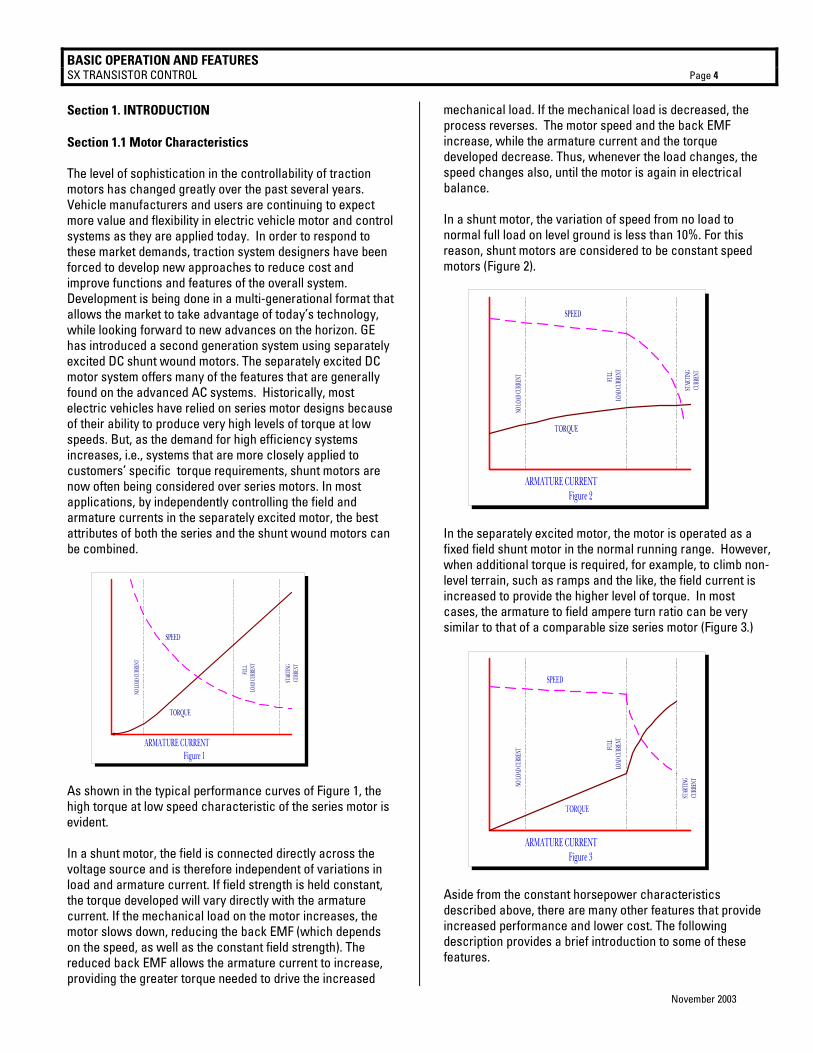
Section 1.1 Motor Characteristics The level of sophistication in the controllability of traction motors has changed greatly over the past several years. Vehicle manufacturers and users are continuing to expect more value and flexibility in electric vehicle motor and control systems as they are applied today. In order to respond to these market demands, traction system designers have been forced to develop new approaches to reduce cost and improve functions and features of the overall system. Development is being done in a multi-generational format that allows the market to take advantage of today’s technology, while looking forward to new advances on the horizon. GE has introduced a second generation system using separately excited DC shunt wound motors. The separately excited DC motor system offers many of the features that are generally found on the advanced AC systems. Historically, most electric vehicles have relied on series motor designs because of their ability to produce very high levels of torque at low speeds. But, as the demand for high efficiency systems increases, i.e., systems that are more closely applied to customers’ specific torque requirements, shunt motors are now often being considered over series motors. In most applications, by independently controlling the field and armature currents in the separately excited motor, the best attributes of both the series and the shunt wound motors can be combined.
NO LO
AD CU
RREN
T
FULL
LOAD
CURR
ENT
STAR
TING
CURR
ENT
ARMATURE CURRENTFigure 1
SPEED
TORQUE
As shown in the typical performance curves of Figure 1, the high torque at low speed characteristic of the series motor is evident. In a shunt motor, the field is connected directly across the voltage source and is therefore independent of variations in load and armature current. If field strength is held constant, the torque developed will vary directly with the armature current. If the mechanical load on the motor increases, the motor slows down, reducing the back EMF (which depends on the speed, as well as the constant field strength). The reduced back EMF allows the armature current to increase, providing the greater torque needed to drive the increased
mechanical load. If the mechanical load is decreased, the process reverses. The motor speed and the back EMF increase, while the armature current and the torque developed decrease. Thus, whenever the load changes, the speed changes also, until the motor is again in electrical balance. In a shunt motor, the variation of speed from no load to normal full load on level ground is less than 10%. For this reason, shunt motors are considered to be constant speed motors (Figure 2).
NO
LOAD
CURR
ENT
FULL
LOAD
CURR
ENT
STAR
TING
CURR
ENT
ARMATURE CURRENTFigure 2
SPEED
TORQUE
In the separately excited motor, the motor is operated as a fixed field shunt motor in the normal running range. However, when additional torque is required, for example, to climb non-level terrain, such as ramps and the like, the field current is increased to provide the higher level of torque. In most cases, the armature to field ampere turn ratio can be very similar to that of a comparable size series motor (Figure 3.)
NO LO
AD CU
RREN
T FULL
LOAD
CURR
ENT
STAR
TING
CURR
ENT
ARMATURE CURRENTFigure 3
SPEED
TORQUE
Aside from the constant horsepower characteristics described above, there are many other features that provide increased performance and lower cost. The following description provides a brief introduction to some of these features.

BASIC OPERATION AND FEATURES SX TRANSISTOR CONTROL Page 5
November 2003
Section 1. 2 Solid-State Reversing The direction of armature rotation on a shunt motor is determined by the direction in which current flows through the field windings. Because of the shunt motor field, typically only requires about 10% of the armature current at full torque, it is normally cost effective to replace the double-pole, double-throw reversing contactor with a low power transistor H-Bridge circuit (Figure 4).
By energizing the transistors in pairs, current can be made to flow in either direction in the field. The field and armature control circuits typically operate at 12KHZ to 15KHZ, a frequency range normally above human hearing. This high frequency, coupled with the elimination of directional contactors, provides for very quiet vehicle operation. The line contactor is normally the only contactor required for the shunt motor traction circuit. This contactor is used for both pre-charge of the line capacitors and for emergency shut down of the motor circuit, in case of problems that would cause a full motor torque condition. The line can be energized and de-energized by the various logic combinations of the vehicle, i.e. activate on key, seat or start switch closure, and de-energize on time out of idle vehicle. Again, these options add to the quiet operation of the vehicle. Section 1. 3 Flexible System Application Because the shunt motor controller has the ability to control both the armature and field circuits independently, the system can normally be adjusted for maximum system efficiencies at certain operating parameters. Generally speaking, with the ability to independently control the field and armature, the motor performance curve can be maximized through proper control application. Section 1. 4 More Features with Fewer Components
Field weakening with a series wound motor is accomplished by placing a resistor in parallel with the field winding of the motor. Bypassing some of the current flowing in the field into the resistor causes the field current to be less, or weakened. With the field weakened, the motor speed will increase, giving the effect of “overdrive”. To change the “overdrive speed”, it is necessary to change the resistor value. In a separately excited motor, independent control of the field current provides for infinite adjustments of “overdrive” levels,
between the motor base speed and maximum weak field. The desirability of this feature is enhanced by the elimination of the contactor and resistor required for field weakening with a series motor. With a separately excited motor, overhauling speed limit, or downhill speed, will also be more constant. By its nature, the shunt motor will try to maintain a constant speed downhill. This characteristic can be enhanced by increasing the field strength with the control. Overhauling load control works in just the opposite way of field weakening, as armature rotation slows with the increase of current in the field. An extension of this feature is a zero-speed detect feature which prevents the vehicle from free-wheeling down an incline, should the operator neglect to set the brake.
Regenerative braking (braking energy returned to the battery) may be accomplished completely with solid-state technology. The main advantage of regenerative braking is increased motor life. Motor current is reduced by 50% or better during braking while maintaining the same braking torque as electrical braking with a diode clamp around the armature. The lower current translates into longer brush life and reduced motor heating. Solid state regenerative braking also eliminates a power diode, current sensor and contactor from the circuit. For GE, the future is now, as we make available a new generation of electric traction motor systems for electric vehicles having separately excited DC shunt motors and controls. Features that were once thought to be only available on future AC or brushless DC technology vehicles systems are now achievable and affordable. Section 2. FEATURES OF SX FAMILY OF TRANSISTOR MOTOR CONTROLLERS Section 2.1 Performance Section 2.1.1 Oscillator Card Features Section 2.1.1.a Standard Operation The oscillator section of the card has two adjustable features, creep speed and minimum field current. With the accelerator at maximum ohms or volts, the creep speed can be adjusted by Function 2 of the Handset or a trimpot. The field control
FUSE
LINE
CAPARM F2F1
Q2
Q4
Q3
Q5
Q1
POS
NEG
Figure 4
A1 +
A2 -Q6

BASIC OPERATION AND FEATURES SX TRANSISTOR CONTROL Page 6
November 2003
section allows the adjustment of the field weakening level in order to set the top speed of the motor. This top speed function (Minimum Field Current) is enabled when the armature current is less than the value set by Function 24 and the accelerator input voltage is less than 1 volt. Top Speed can be adjusted by Function 7 of the Handset or a trimpot. The % ON-time has a range of approximately 0 to 100 percent. The SX controllers operate at a constant frequency and the % ON-time is controlled by the pulse width of the voltage/current applied to the motor circuits. Section 2.1.1.b Control Acceleration This feature allows for adjustment of the rate of time it takes for the control to accelerate to 100% applied battery voltage to the motor on hard acceleration. Armature C/A is adjusted by Function 3 from 0.1 to 6 seconds. Section 2.1.2 Current Limit This circuit monitors motor current by utilizing sensors in series with the armature and field windings. The information detected by the sensor is fed back to the card so that current may be limited to a preset value. If heavy load currents are detected, this circuit overrides the oscillator and limits the average current to a value set by Function 4 and Function 8 of the Handset. The C/L setting is based on the maximum thermal rating of the control. Because of the flyback current through Q6, the motor current is usually greater than battery current, except at 100% ON time. Section 2.1.3 Braking Section 2.1.3.a Plug Braking Slow down is accomplished when reversing direction by providing a small amount of retarding torque for deceleration. If the vehicle is moving, and the directional lever is moved from one direction to the other, the plug signal is initiated. Once the plug signal has been initiated, the field is reversed, and the armature current is regulated to the plug current limit as set by Function 5. Armature current is regulated by increasing the field current as the vehicle slows down. Once the field current reaches a preset value, set by Function 10, and armature plug current can no longer be maintained, the braking function is canceled, and the control reverts back to motoring. All energy produced by the motor during plugging is dumped as heat into the motor in this braking mode. Section 2.1.3.b Regenerative Braking to Zero Speed Slow down is accomplished when reversing direction by providing a small amount of retarding torque for deceleration. If the vehicle is moving, and the directional lever is moved from one direction to the other, the regen signal is initiated.
Once the regen signal has been initiated, the field current is increased. Armature current is regulated to the regen current limit as set by Function 9. As the vehicle slows down, the field current continues to increase, and transistor Q2 begins to chop. The field current will increase until it reaches a preset value set by Function 10, and transistor Q2 on-time will increase until it reaches 100% on-time. Once both of the above conditions have been met, and the regen current limit can no longer be maintained, the braking function is canceled. The fields will then reverse, and the control reverts back to motoring. Part of the energy produced by the motor during regen is returned to the battery, and the remainder is dumped into the motor as heat. Section 2.1.3.c Throttle Position Plug Braking This feature allows control of the plugging distance based on throttle position when there has been a “directional switch” change. Throttle position will reduce the plugging current as the throttle is returned to the creep speed position. Maximum plug current is obtained with the accelerator in the top speed position. Section 2.1.4 Auxiliary Speed Control Section 2.1.4.a Field Weakening This function allows the adjustment of the field weakening level in order to set the top speed of the motor. The function is enabled when the armature current is less than the value set by Function 24 . It is important to note that this function is used to optimize motor and control performance, and this setting will be determined by GE and OEM engineers at the time of vehicle development. This setting must not be changed by field personnel without the permission of the OEM. Section 2.1.4.b Speed Limits This feature provides a means to control speed by limiting motor volts utilizing three “adjustable speed limits” initiated by individual limit switches. The NC switches are connected between input points on the control card and battery negative. The lower motor volt limit always takes priority when more than one switch input is open. This motor volt limit regulates top speed of the transistor controller, but actual truck speed will vary at any set point, depending on the loading of the vehicle. Each speed limit can be adjusted with the Handset using Functions 11, 12 and 13 for speed limits SL1, SL2 and SL3, respectively. SL1 is active in all card types, and must be disabled with the Handset, if speed limits are not used. Section 2.1.5 Ramp Operation
BASIC OPERATION AND FEATURES SX TRANSISTOR CONTROL Page 7
November 2003
Section 2.1.5.a Ramp Start This feature provides maximum control torque to restart a vehicle on an incline. The memory for this function is the directional switch. When stopping on an incline, the directional switch must be left in its original or neutral position to allow the control to initiate full power when restarted. The accelerator potentiometer input will modulate ramp start current. Section 2.1.5.b Anti-Rollback This feature provides retarding torque to limit rollback speed in the non-travel direction when the ACC pedal is released when stopping on a grade, or when the brake pedal is released when starting on a grade. This feature forces the vehicle to roll very slowly down the grade when the accelerator or brake is released. Because the vehicle can gain significant speed during roll-back, the torque needed to re-start on the ramp is lower than an unrestricted roll-back speed. Section 2.1.6 On-Board Coil Drivers and Internal Coil Suppression Coil drivers for the LINE and SP or BYPASS contactors are on-board the control card. These contactors must have coils rated for the vehicle battery volts. Section 2.2 System Protective Override Section 2.2.1 Static Return to Off (SRO) This inherent safety feature of the control is designed to require the driver to return the directional lever to the neutral position anytime he leaves the vehicle and returns. Additionally, if the seat switch or key switch is opened, the control shuts off and cannot be restarted until the directional lever is returned to neutral. A time delay of approximately 2 seconds is built into the seat switch input to allow momentary opening of the seat switch, if a bump is encountered. Section 2.2.2 Accelerator Volts Hold Off This feature checks the voltage level at the accelerator input whenever the key switch or seat switch is activated. If, at start-up, the voltage is greater than 0.9 volts, the control will not operate. This feature assures that the control is calling for low speed operation at start up. Section 2.2.3 Pulse Monitor Trip (PMT) The PMT design contains three features which shut down, or lock out, control operation if a fault conditions occurs that would cause a disruption of normal vehicle operation: • Look ahead
• Look again • Automatic look again and reset The PMT circuit will not allow the control to start under the following conditions: • The control monitors both armature and field FET's at
start-up and during running. • The control will not allow the line contactor to close at
start-up, or will drop it out during running, if either the armature or field FET's are defective, so as to cause uncontrolled truck movement.
Section 2.2.4 Thermal Protector (TP) This temperature sensitive device is internal to the power transistor (Q1) module. If the transistor's temperature begins to exceed the design limits, the thermal protector will lower the maximum current limit to 200 amps. As the control cools, the thermal protector will automatically reset, returning the control to full power. Section 2.2.5 Low Voltage Detection Batteries under load, particularly if undersized or more than 80 percent discharged, will produce low voltages at the control terminals. The SX control is designed for use down to 50 percent of a nominal battery voltage of 36-84 volts, and 75 percent of a nominal battery voltage of 24 volts. Lower battery voltage may cause the control to operate improperly, however, the resulting PMT should open the Line contactor, in the event of a failure. Section 2.3 Diagnostics Section 2.3.1 Status Codes Section 2.3.1.a Standard Status Codes The SX control has a wide variety of Status Codes that assist the service technician and operator in trouble shooting the vehicle. If mis-operation of the vehicle occurs, a status code will be displayed on the Dash Display for vehicles so equipped, or be available from the status code displayed when the Handset is plugged into the “Y” plug of the logic card. With the status code number, follow the procedures outlined in DIAGNOSTIC STATUS CODES to determine the problem and appropriate corrective action. Note: The Status Code Instruction Sheets do not purport to cover all possible causes of a display of a "status code ". They do provide instructions for checking the most direct inputs that can cause status codes to appear.
BASIC OPERATION AND FEATURES SX TRANSISTOR CONTROL Page 8
November 2003
Section 2.3.1.b Stored Status Codes This feature records the last 16 "Stored Status Codes" that have caused a PMT controller shut down and/or disrupted normal vehicle operation. (PMT type faults are reset by cycling the key switch). These status codes, along with the corresponding BDI and hourmeter readings, can be accessed with the Handset, or by using the RS 232 communications port and dumping the information to a Personal Computer terminal. Section 2.3.2 Hourmeter Readings This feature will display the recorded hours of use of the traction and pump control to the Dash Display each time the key switch is turned off. Section 2.3.2.a Maintenance Alert Status Code This feature is used to display a “99” status code when the vehicle operating hours match the hours set into the maintenance alert register. This feature is set with the Handset using Functions 19 and 20. The operator is alerted that maintenance on the vehicle is required. Section 2.3.3 Battery Discharge Indication (BDI) The latest in microprocessor technology is used to provide accurate battery state of charge information and to supply passive and active warning signals to the vehicle operator. Features and functions: • Displays 100 to 0 percent charge. • Display blinks with 20% charge. Option to disable pump
circuit with 9% charge. Auto ranging for 36/48 volt operation. Adjustable for use on 24 to 80 volts.
Section 2.3.3.a Internal Resistance Compensation This feature is used when the Battery Discharge Indicator is present. Adjustment of this function optimizes BDI with among different brands of batteries. Section 2.3.4 Handset This is a multi-functional tool used with the LX, ZX, and SX Series GE solid-state controls. The Handset consists of a Light Emitting Diode (LED) display and a keyboard for data entry. Note, for ordering purposes, a separate Handset part number is required for SX controls. Features and functions: • Monitor existing system status codes for both traction
and pump controls. Monitor intermittent random status codes.
• Monitor battery state of charge, if available. • Monitor hourmeter reading on traction and pump
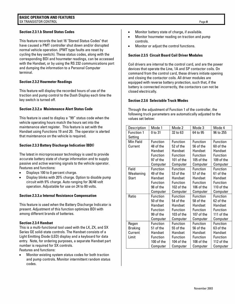
controls. • Monitor or adjust the control functions. Section 2.3.5 Circuit Board Coil Driver Modules Coil drivers are internal to the control card, and are the power devices that operate the Line, 1A and SP contactor coils. On command from the control card, these drivers initiate opening and closing the contactor coils. All driver modules are equipped with reverse battery protection, such that, if the battery is connected incorrectly, the contactors can not be closed electrically. Section 2.3.6 Selectable Truck Modes Through the adjustment of Function 1 of the controller, the following truck parameters are automatically adjusted to the values set below: Description Mode 1 Mode 2 Mode 3 Mode 4 Function 1 Setting
0 to 31 32 to 63 64 to 95 96 to 255
Min Field Current
Function 48 of the Handset Function 97 of the Computer
Function 52 of the Handset Function 101 of the Computer
Function 56 of the Handset Function 105 of the Computer
Function 60 of the Handset Function 109 of the Computer
Field Weakening Start
Function 49 of the Handset Function 98 of the Computer
Function 53 of the Handset Function 102 of the Computer
Function 57 of the Handset Function 106 of the Computer
Function 61 of the Handset Function 110 of the Computer
Ratio Function 50 of the Handset Function 99 of the Computer
Function 54 of the Handset Function 103 of the Computer
Function 58 of the Handset Function 107 of the Computer
Function 62 of the Handset Function 111 of the Computer
Regen Braking Current Limit
Function 51 of the Handset Function 100 of the Computer
Function 55 of the Handset Function 104 of the Computer
Function 56 of the Handset Function 108 of the Computer
Function 63 of the Handset Function 112 of the Computer

OUTLINE DRAWINGS, ELEMENTARY DRAWINGS AND INPUTS/OUTPUT SX TRANSISTOR CONTROL Page 9
November 2003
Section 3.0 ORDERING INFORMATION, ELEMENTARY AND OUTLINE DRAWINGS Section 3.1 Ordering Information for Separately Excited Controls
Example: Part Number: IC3645 SE 4 D 33 2 C3 Argument Number: 01 02 03 04 05 06 07 Argument 01: Basic Electric Vehicle Control Number Argument 02: Control Type: SH = Separately Excited Control ( Plugging ) SR = Separately Excited Control ( Regen to Zero ) Argument 03: Operating Voltage: 1 = 120 volts 5 = 36/48 volts 2 = 24 volts 6 = 24/36 volts 3 = 36 volts 7 = 72/80 volts 4 = 48 volts Argument 04: Package Size: D = 6.86” X 6.67” R = 6.86” X 8.15” U = 8.66” X 8.13” W = 8.66” X 10.83” Argument 05: Armature Current ( 2 characters ) 22 = 220 Amps 33 = 330 Amps 40 = 400 Amps etc. Argument 06: Field Current ( 1 character ) 2 = 20 Amps 3 = 30 Amps 4 = 40 Amps etc. Argument 07: Customer / Revision A1 = Customer A / Revision 1 B1 = Customer B / Revision 1 etc.
OUTLINE DRAWINGS, ELEMENTARY DRAWINGS AND INPUTS/OUTPUT SX TRANSISTOR CONTROL Page 10
November 2003
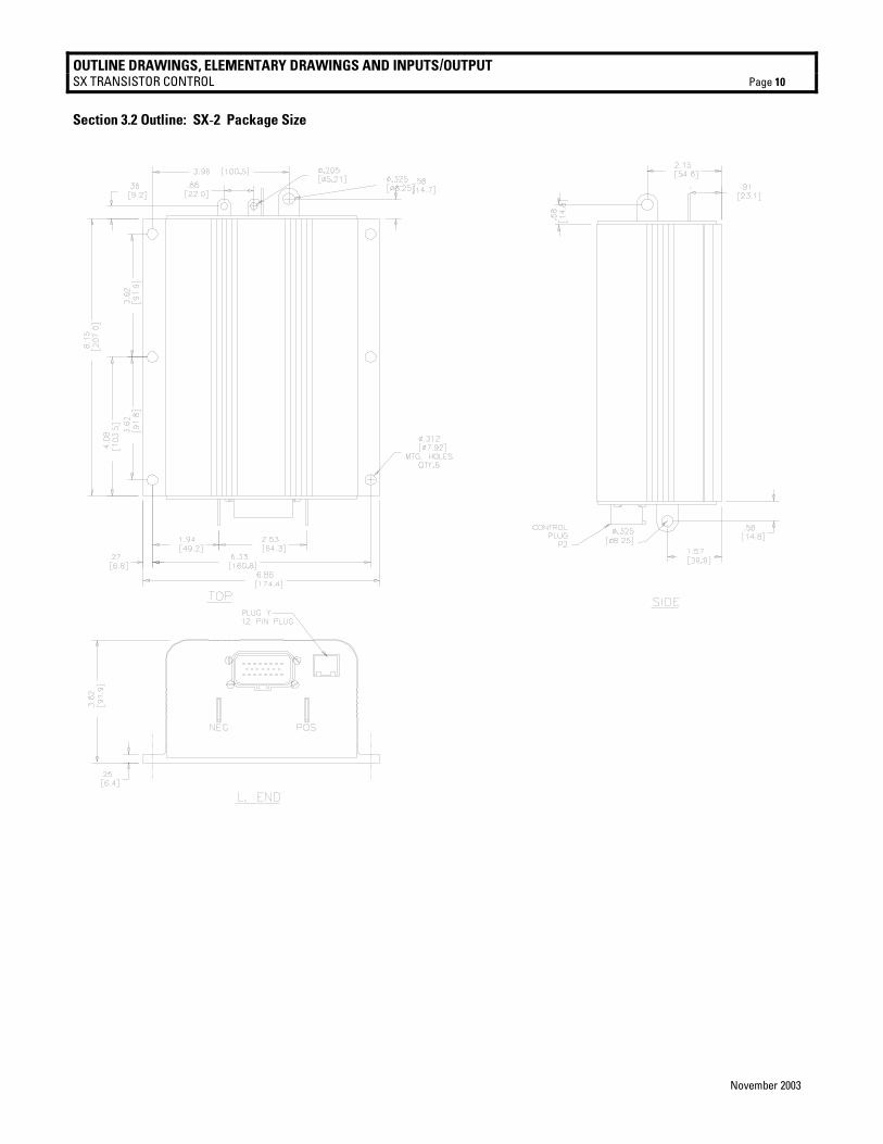
Section 3.2 Outline: SX-2 Package Size
OUTLINE DRAWINGS, ELEMENTARY DRAWINGS AND INPUTS/OUTPUT SX TRANSISTOR CONTROL Page 11
November 2003
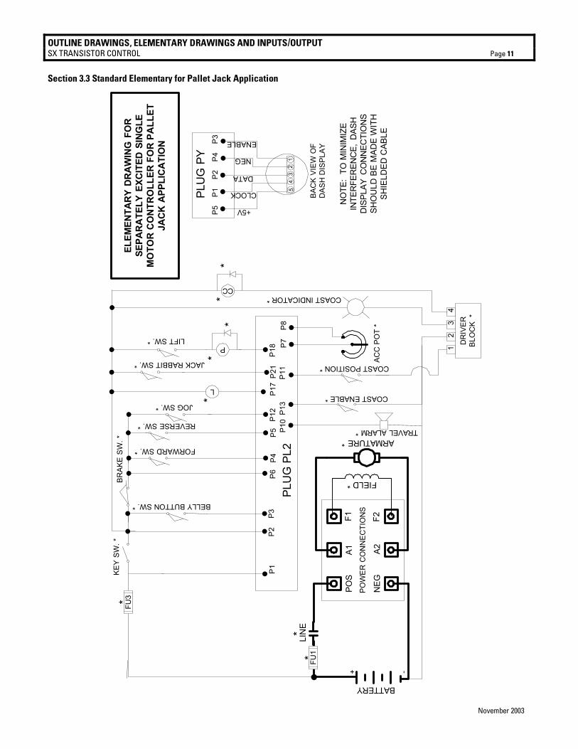
Section 3.3 Standard Elementary for Pallet Jack Application
ELEM
ENTA
RY
DRA
WIN
G F
OR
SEPA
RA
TELY
EXC
ITED
SIN
GLE
MO
TOR
CO
NTR
OLL
ER F
OR
PA
LLET
JACK
APP
LIC
ATIO
N
NO
TE:
TO M
INIM
IZE
INTE
RFE
REN
CE,
DAS
HD
ISPL
AY C
ON
NEC
TIO
NS
SHO
ULD
BE
MAD
E W
ITH
SHIE
LDED
CAB
LE
PLU
G P
Y
BAC
K VI
EW O
FD
ASH
DIS
PLAY
P5
P1
P2
P
4
P3
ARMATURE *
KEY
SW. *
P2P4
P5
BRAK
E SW
. *
P17
P3
L
BELLY BUTTON SW. *
JACK RABBIT SW. *
P21
P12
JOG SW. *
P6
PLU
G P
L2P1
8
LIFT SW. *
P13
FORWARD SW. *
REVERSE SW. *
COAST ENABLE *
POW
ER C
ON
NEC
TIO
NS
POS
A1F1
NEG
A2F2
FIELD *
P7P8
ACC
PO
T *
TRAVEL ALARM *P10
DR
IVER
BLO
CK
*
12
34
COAST POSITION *
P11
+ -
P1
LIN
E
BATTERY
P
CC
**
**
COAST INDICATOR *
*
FU1
FU3*
**
54
32
1
+5V
CLOCK
DATA
NEG
ENABLE
OUTLINE DRAWINGS, ELEMENTARY DRAWINGS AND INPUTS/OUTPUT SX TRANSISTOR CONTROL Page 12
November 2003
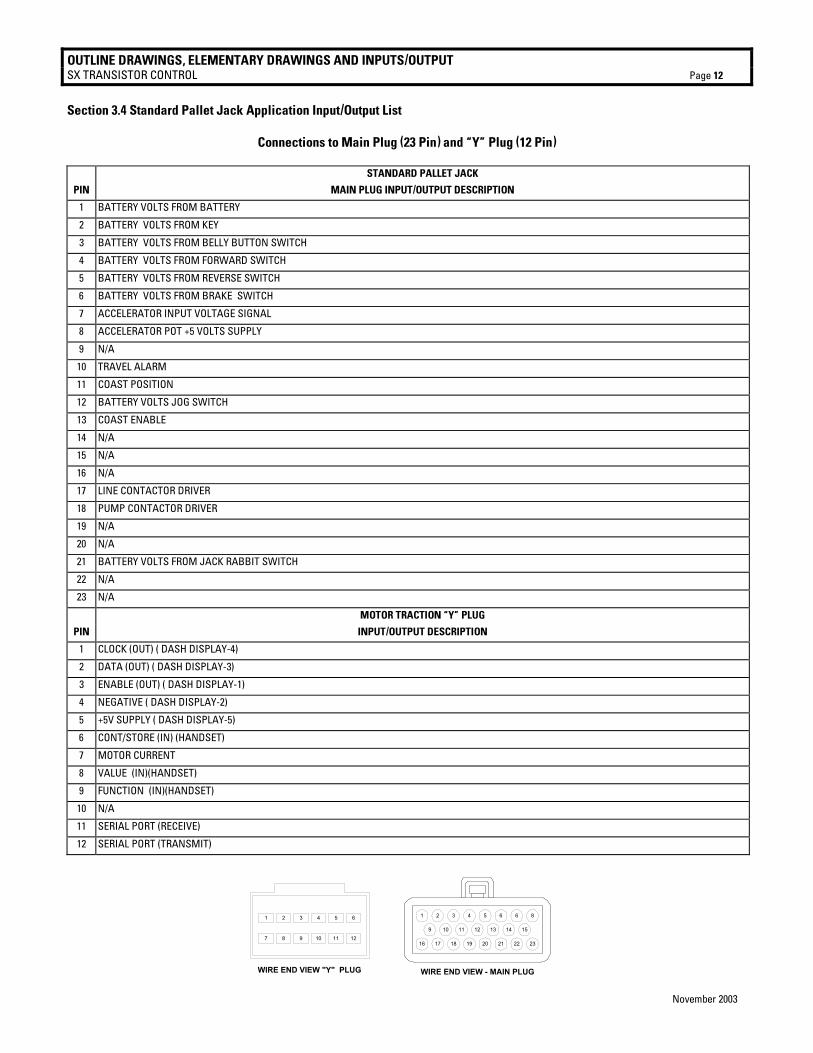
Section 3.4 Standard Pallet Jack Application Input/Output List
Connections to Main Plug (23 Pin) and “Y” Plug (12 Pin)
STANDARD PALLET JACK
PIN MAIN PLUG INPUT/OUTPUT DESCRIPTION
1 BATTERY VOLTS FROM BATTERY
2 BATTERY VOLTS FROM KEY
3 BATTERY VOLTS FROM BELLY BUTTON SWITCH
4 BATTERY VOLTS FROM FORWARD SWITCH
5 BATTERY VOLTS FROM REVERSE SWITCH
6 BATTERY VOLTS FROM BRAKE SWITCH
7 ACCELERATOR INPUT VOLTAGE SIGNAL
8 ACCELERATOR POT +5 VOLTS SUPPLY
9 N/A
10 TRAVEL ALARM
11 COAST POSITION
12 BATTERY VOLTS JOG SWITCH
13 COAST ENABLE
14 N/A
15 N/A
16 N/A
17 LINE CONTACTOR DRIVER
18 PUMP CONTACTOR DRIVER
19 N/A
20 N/A
21 BATTERY VOLTS FROM JACK RABBIT SWITCH
22 N/A
23 N/A
MOTOR TRACTION “Y” PLUG
PIN INPUT/OUTPUT DESCRIPTION
1 CLOCK (OUT) ( DASH DISPLAY-4)
2 DATA (OUT) ( DASH DISPLAY-3)
3 ENABLE (OUT) ( DASH DISPLAY-1)
4 NEGATIVE ( DASH DISPLAY-2)
5 +5V SUPPLY ( DASH DISPLAY-5)
6 CONT/STORE (IN) (HANDSET)
7 MOTOR CURRENT
8 VALUE (IN)(HANDSET)
9 FUNCTION (IN)(HANDSET)
10 N/A
11 SERIAL PORT (RECEIVE)
12 SERIAL PORT (TRANSMIT)
1 2 3 4 5 6 1 2 3 4 5 6 6 8
9 10 11 12 13 14 15
16 17 18 19 20 21 22 23
WIRE END VIEW - MAIN PLUGWIRE END VIEW "Y" PLUG
7 8 9 10 11 12
DIAGNOSTIC STATUS CODES SX TRANSISTOR CONTROL Page 13
November 2003
Section 4.0 TROUBLESHOOTING AND DIAGNOSTIC STATUS CODES Section 4.1 General Maintenance Instructions The transistor control, like all electrical apparatus, does have some thermal losses. The semiconductor junctions have finite temperature limits, above which these devices may be damaged. For these reasons, normal maintenance should guard against any action which will expose the components to excessive heat and/or those conditions which will reduce the heat dissipating ability of the control, such as restricting air flow. The following Do’s and Don’t’s should be observed: Any controls that will be applied in ambient temperatures over 100° F (40° C) should be brought to the attention of the vehicle manufacturer. All external components having inductive coils must be filtered. Refer to vehicle manufacturer for specifications. The wiring should not be directly steam cleaned. In dusty areas, blow low-pressure air over the control to remove dust. In oily or greasy areas, a mild solution of detergent or denatured alcohol can be used to wash the control, and then low-pressure air should be used to completely dry the control. For the control to be most effective, it must be mounted against the frame of the vehicle. The metal vehicle frame, acting as an additional heat sink, will give improved vehicle performance by keeping the control package cooler. Apply a thin layer of heat-transfer grease (such as Dow Corning 340) between the control heat sink and the vehicle frame. Control wire plugs and other exposed transistor control parts should be kept free of dirt and paint that might change the effective resistance between points. CAUTION: The vehicle should not be plugged when the vehicle is jacked up and the drive wheels are in a free wheeling position. The higher motor speeds can create excessive voltages that can be harmful to the control. Do not hipot (or megger) the control. Refer to control manufacturer before hipotting. Use a lead-acid battery with the voltage and ampere hour rating specified for the vehicle. Follow normal battery maintenance procedures, recharging before 80 percent discharged with periodic equalizing charges. Visual inspection of GE contactors contained in the traction and pump systems is recommended to occur during every
160 hours of vehicle operation. Inspection is recommended to verify that the contactors are not binding and that the tips are intact and free of contaminants. GE does not recommend that any type of welding be performed on the vehicle after the installation of the control(s) in the vehicle. GE will not honor control failures during the warranty period when such failures are attributed to welding while the control is installed in the vehicle. Section 4.2 Cable Routing and Separation Electrical noise from cabling of various voltage levels can interfere with a microprocessor-based control system. To reduce this interference, GE recommends specific cable separation and routing practices, consistent with industry standards. Section 4.2.1 Application Responsibility The customer and customer’s representative are responsible for the mechanical and environmental locations of cables. They are also responsible for applying the level rules and cabling practices defined in this section. To help ensure a lower cost, noise-free installation, GE recommends early planning of cable routing that complies with these level separation rules. On new installations, sufficient space should be allowed to efficiently arrange mechanical and electrical equipment. On vehicle retrofits, level rules should be considered during the planning stages to help ensure correct application and a more trouble-free installation. Section 4.2.2. Signal/Power Level Definitions The signal/power carrying cables are categorized into four defining levels: low, high, medium power, and high power. Within those levels, signals can be further divided into classes. Sections 4.2.2.a through 4.2.2.d define these levels and classes, with specific examples of each. Section 4.2.3 contains recommendations for separating the levels. Section 4.2.2.a Low-Level Signals (Level L) Low-level signals are designated as level L. These consist of: • Analog signals 0 through ±15 V • Digital signals whose logic levels are less than 15 V DC • 4 – 20 mA current loops • DC busses less than 15 V and 250 mA The following are specific examples of level L signals used in drive equipment cabling: • Control common tie • DC buses feeding sensitive analog or digital hardware
DIAGNOSTIC STATUS CODES SX TRANSISTOR CONTROL Page 14
November 2003
• All wiring connected to components associated with sensitive analog hardware with less than 5V signals (for example, potentiometers and tachometers)
• Digital tachometers and resolvers • Dash display cabling • RS-232 cabling Note: Signal inputs to analog and digital blocks should be run as shielded twisted-pair (for example, inputs from tachometers, potentiometers, and dash displays). Section 4.2.2.b High-Level Signals (Level H) High-level signals are designated as level H. These signals consist of: • Analog and digital signals greater than 15 V DC and
less than 250 mA For example, switch inputs connected to battery volts are examples of level H signals used in drive equipment cabling. Section 4.2.2.c Medium-Power Signals (Level MP) Medium power signals are designated as level MP. These signals consist of: • DC switching signals greater than 15 V • Signals with currents greater than 250 mA and less than
10A The following are specific examples of level MP signals used in drive equipment cabling: • DC busses less than 10 A • Contactor coils less than 10 A • Machine fields less than 10 A Section 4.2.2.d High Power Signals (Level HP) Power wiring is designated as level HP. This consists of DC buses and motor wiring with currents greater than 10 A. The following are specific examples of level HP signals used in drive equipment cabling: • Motor armature loops • DC outputs 10 A and above • Motor field loops 10 A and above Section 4.2.3. Cable Spacing Guidelines Recommended spacing (or clearance) between cables (or wires) is dependent on the level of the wiring inside them. For correct level separation when installing cable, the customer must apply the general guidelines (section 4.2.3.a), outlined below.
Section 4.2.3.a General Cable Spacing The following general practices should be used for all levels of cabling: • All cables and wires of like signal levels and power
levels must be grouped together. • In general, different levels must run in separate wire
bundles, as defined in the different classes, identified above. Intermixing cannot be allowed, unless noted by exception.
• Interconnecting wire runs should carry a level designation.
• If wires are the same level and same type signal, group those wires from one location to any other location together in multiconductor cables or bind them together with twine or zip-ties.
• When unlike signals must cross, cross them in 90° angles at a maximum spacing. Where it is not possible to maintain spacing, place a grounded steel barrier between unlike levels at the crossover point.
Section 4.2.4 Cabling for Vehicle Retrofits Reducing electrical noise on vehicle retrofits requires careful planning. Lower and higher levels should never encircle each other or run parallel for long distances. It is practical to use existing wire runs or trays as long as the level spacing (see section 4.2.2) can be maintained for the full length of the run. Existing cables are generally of high voltage potential and noise producing. Therefore, route levels L and H in a path separate from existing cables, whenever possible. For level L wiring, use barriers in existing wire runs to minimize noise potential. Do not loop level L signal wires around level H, level MP, or HP wires. Section 4.2.5 RF Interference To prevent radio frequency (RF) interference, care should be taken in routing power cables in the vicinity of radio-controlled devices. Section 4.2.6 Suppression Unless specifically noted otherwise, suppression (for example, a snubber) is required on all inductive devices controlled by an output. This suppression minimizes noise and prevents damage caused by electrical surges.
DIAGNOSTIC STATUS CODES SX TRANSISTOR CONTROL Page 15
November 2003
Section 4.3 Recommended Lubrication of Pins and Sockets Prior to Installation Beginning in January of 1999, GE implemented the addition of a lubricant to all connections using pins and sockets on EV100/EV200 and Gen II products. Any connection made by GE to the A, B, X, Y, or Z plugs will have the lubricant NYE 760G added to prevent fretting of these connections during vehicle operation. Fretting occurs during microscopic movement at the contact points of the connection. This movement exposes the base metal of the connector pin which, when oxygen is present, allows oxidation to occur. Sufficient build up of the oxidation can cause intermittent contact and intermittent vehicle operation. This can occur at any similar type of connection, whether at the control or in any associated vehicle wiring, and the resultant intermittent contact can provide the same fault indication as actual component failure. The addition of the NYE 760G lubricant will prevent the oxidation process by eliminating the access of oxygen to the contact point. GE recommends the addition of this lubricant to the 12 pin and 23 pin plugs of all new Gen II controls at the time of their installation into a vehicle. When servicing existing vehicles exhibiting symptoms of intermittent mis-operation or shutdown by the GE control, GE recommends the addition of this lubricant to all 12 and 23 pin plugs, after proper cleaning of the connectors, as a preventative measure to insure fretting is not an issue before GE control replacement. . Also, for long term reliable control operation, the plug terminals must be maintained per these instructions with the recommended contact cleaner and lubricant which provides a high degree of environmental and fretting protection. New and re-manufactured control plugs are cleaned and lubricated prior to shipment from the factory. However, in applications where severe vibration or high temperature cycling and excessive humidity ( such as freezers ) are present, it is recommended that the plug terminals be cleaned and lubricated every year, per this instructions. In normal applications, plug maintenance should be performed every two years, unless intermittent problems arise with the plugs, requiring more immediate attention. Warning: Do not use any other cleaners or lubricants other than the ones specified. WARNING: Before conducting maintenance on the vehicle, jack up the drive wheels, disconnect the battery and discharge the capacitors. Consult the Operation and Service Manual for your particular vehicle for details on discharging the capacitors; this procedure differs between SCR and Transistor controls.
1. Disconnect plug from controller or mating plug.
2. Locate the plug that contains the socket (female) terminals. Maintenance needs only to be performed on the plug containing the socket (female) type terminals. Reconnecting the plugs will lubricate the pin (male) terminals.
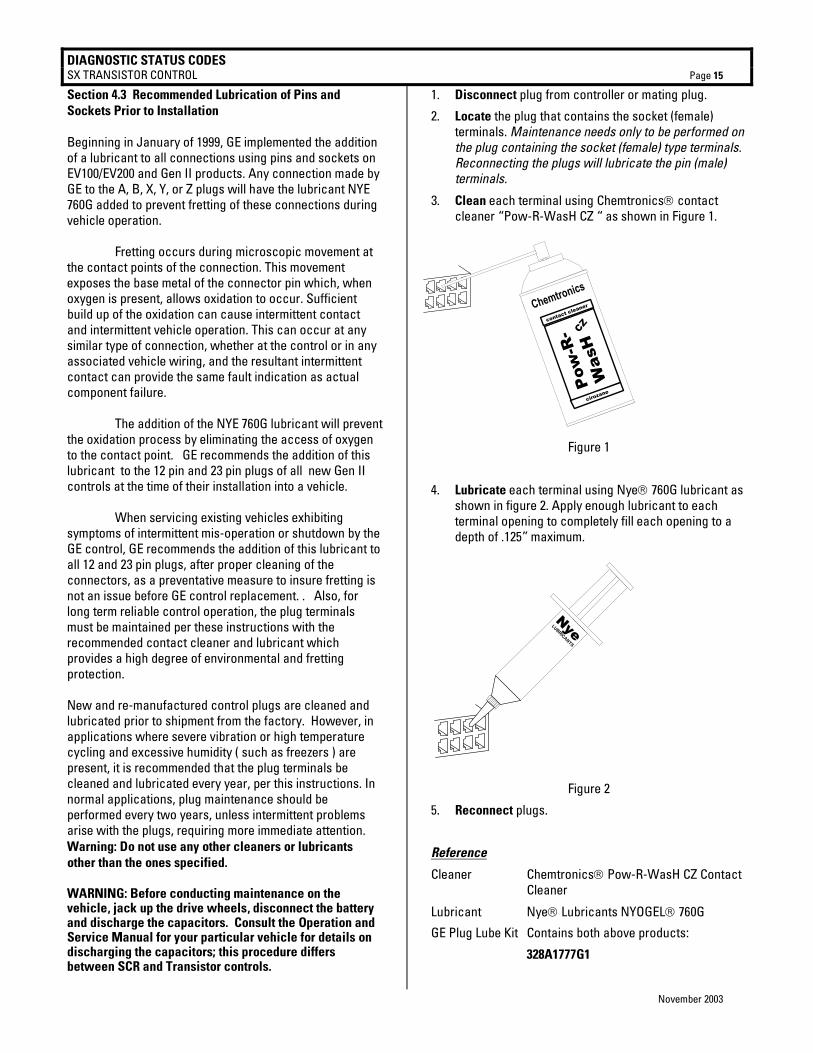
3. Clean each terminal using Chemtronics contact cleaner “Pow-R-WasH CZ “ as shown in Figure 1.
Figure 1
4. Lubricate each terminal using Nye 760G lubricant as shown in figure 2. Apply enough lubricant to each terminal opening to completely fill each opening to a depth of .125” maximum.
Figure 2
5. Reconnect plugs.
Reference
Cleaner Chemtronics Pow-R-WasH CZ Contact Cleaner
Lubricant Nye Lubricants NYOGEL 760G
GE Plug Lube Kit Contains both above products:
328A1777G1
Chemtronics
Pow
-R-
Was
HCZ
contact cleaner
cirozane
NyeLUBRICANTS

DIAGNOSTIC STATUS CODES SX TRANSISTOR CONTROL Page 16
November 2003
Section 4.4 Controller Mounting Guidelines In the design of the GE family of motor controls, performance assumptions were made based on heat transfer between the control and the ambient environment. The vehicle mounting surface acts as a heat sink, which increases the effective surface area for heat dissipation. If this assumed heat transfer is not achieved during control installation and operation, GE controllers will fall short of their anticipated performance. It should be noted that the condition of the mounting surface, and the quality of the resulting interface between the control and the vehicle, can significantly hinder heat transfer from the control. The presence of contaminants, or of air voids created by surface inconsistencies in either the vehicle or the control, degrade the control’s capacity for heat transfer. The control’s performance is de-rated proportionally as its own thermal sensors reduce its operation to protect it from damage due to excessive heating. Contained within the software of the GE controls are several diagnostic status codes related to controller thermal performance. Failure to follow these mounting recommendations increases the likelihood of encountering these status codes, through no fault of the control itself, thus voiding controller warranty for units returned solely due to the presence of these status codes. Careful surface preparation, including adequate application of thermal compound, as detailed in the following paragraphs, must be completed during the installation of GE controls. There are many techniques for applying thermal compound, and we have outlined one approach below that has shown to apply a consistent thickness of material. Section 4.4.1 Necessary Tools GE recommends the use of the following components, or equivalent substitutions, during the control installation process:
a) Thermal compound, (Dow Corning #340), maintained per the manufacturer’s recommendations and free of contaminants
b) 3/32” notched trowel, such as a Krusin adhesive spreader, model 00031
c) Calibrated torque wrench (0 – 15 ft-lbs) Section 4.4.2 The GE Control Mounting Surface During the manufacture of the GE control, the surface flatness is maintained at 0.005” per linear inch (not to exceed 0.025” per 10.0 inches). The surface finish of the GE control has an Ra (average roughness) of 64 (microinches), or better. This finish is consistent with cold rolled or extruded aluminum.
Care should always be taken in the handling and storage of controllers. The base of the control should be free from
nicks, bumps, protrusions or any other foreign object that would prevent the control from sitting flush with the vehicle mounting surface. Examine the base of the control to verify that it is in good condition and free from damage or contamination.
Section 4.4.3 Vehicle Mounting Surface The quality of the vehicle mounting surface is critical for the optimum heat transfer between the control and the ambient environment. Conduction through the base of the control is the control’s only means of heat rejection. While GE controls are highly efficient, a few percent of the electrical energy will be converted into heat. As previously mentioned, if this energy is not dissipated through the base of the control, a thermal protector will reduce the performance of the control until the temperature stabilizes. For optimal heat transfer from control to vehicle, the flatness of the vehicle mounting surface should be equivalent to the flatness of the control surface (0.005” per linear inch). Use a straight edge or dial indicator to verify the mounting surface.
The biggest hindrance to heat transfer is the presence of rust, scale, weld splatter or paint on the vehicle mounting surface. If any of these items are noted, prepare the surface per the following guidelines:
a) Clean the mounting surface with a rotary wire
brush until the metal surface is exposed. b) Using 80-100 grit emery paper, sand the
surface until the metal shines. c) Flush the surface clean with an appropriate
liquid de-greaser or parts cleaner. Section 4.4.4 Application of Thermal Compound Due to the minute differences in the control mounting surface and the vehicle mounting surface, small pockets of air will be created. These air pockets will add to the overall thermal resistance of the interface.
To avoid these air pockets and improve thermal conductivity, thermal compound must be applied between the GE control base plate and the vehicle mounting surface. The function of this compound is to conform to surface discrepancies, filling gaps and optimizing the metal-to-metal contact of the control and the vehicle.
a) Prepare the two mounting surfaces (control and vehicle) as indicated above.
b) Using a triangular notched trowel of 3/32” (.09” +/- .01), apply the grease to the vehicle mounting surface.

DIAGNOSTIC STATUS CODES SX TRANSISTOR CONTROL Page 17
November 2003
c) Use straight, non-crossing strokes of the trowel to apply the compound.
d) Make multiple vertical passes until a uniform consistency is achieved.
Krusin adhesive spreader model 00031
Vehicle surface after proper grease application
Section 4.4.5 Mounting the GE Control
a) Place the control unit with desired orientation on mounting plate with mounting holes aligned.
b) Move the control slightly in all directions to eliminate voids and enhance the distribution of the thermal compound.
c) Insert the all of the mounting hardware (4, 6 or 8 bolts, M6 or M8, necessary for the mounting of the respective family of controls).
d) Tighten these bolts (as per sequence shown in diagrams below) to half of the nominal torque value (7.5lb-ft).
e) Lastly, tighten the bolts to the nominal torque value (15 lb-ft), following the same sequence.
Calibrated torque wrench for hardware installation
1 4
3 2
1 3
2
6
4
2
3
5
1
7
5
3
1
6
8
2
4
Proper sequence for use in tightening hardware during control mounting
Section 4.4.6 Maintenance
If it is necessary to remove the control for service, careful consideration must be given to removing the old thermal compound from the control and mounting surface, prior to replacement of the unit. Never re-use thermal compound. Use a putty knife or similar straight edge to carefully remove all thermal compound residue without damaging either mounting surface. Flush the surfaces with a liquid de-greaser or parts cleaner and allow them to dry, before re-applying the thermal compound and mounting the control. Take care not to contaminate the surfaces with hydraulic fluid or battery acid. Section 4.5 General Troubleshooting Instructions Trouble-shooting the SX family of controls should be quick and easy when following the instructions outlined in the following status code instruction sheets. If mis-operation of the vehicle occurs, a status code will be displayed on the Dash Display (for vehicles equipped with a Dash Display) or made available by plugging a Handset into the plug "Y" location, and then reading the status code. With the status code number, follow the procedures outlined in the status code instruction sheets to determine the problem. Important Note: Due to the interaction of the logic card with all vehicle functions, almost any status code or control
DIAGNOSTIC STATUS CODES SX TRANSISTOR CONTROL Page 18
November 2003
fault could be caused by the logic card. After all other status code procedures have been followed and no problem is found, the controller should then be replaced as the last option to correct the problem. The same device designations have been maintained on different controls but the wire numbers may vary. Refer to the elementary and wiring diagrams for your specific control. The wire numbers shown on the elementary diagram will have identical numbers on the corresponding wiring diagrams for a specific vehicle, but these numbers may be different from the numbers referenced in this publication. WARNING: Before trouble-shooting, jack up the drive wheels, disconnect the battery and discharge the capacitors. Reconnect the battery as needed for specific checks. Capacitors should be discharged by connecting a 200 ohm 2 watt resistor between the positive and negative terminals on the control panel. Check resistance on R x 1000 scale from frame to power and control terminals. A resistance of less than 20,000 ohms can cause misleading symptoms. Resistance less than 1000 ohms should be corrected first. Before proceeding, visually check for loose wiring, mis-aligned linkage to the accelerator switch, signs of overheating of components, etc. Tools and test equipment required are: clip leads, volt-ohm meter (20,000 ohms per volt) and basic hand tools.
DIAGNOSTIC STATUS CODES SX TRANSISTOR CONTROL Page 19
November 2003
Section 4.6 Traction Control Status Codes
TRACTION STATUS CODE
DESCRIPTION OF STATUS CAUSE OF STATUS INDICATION
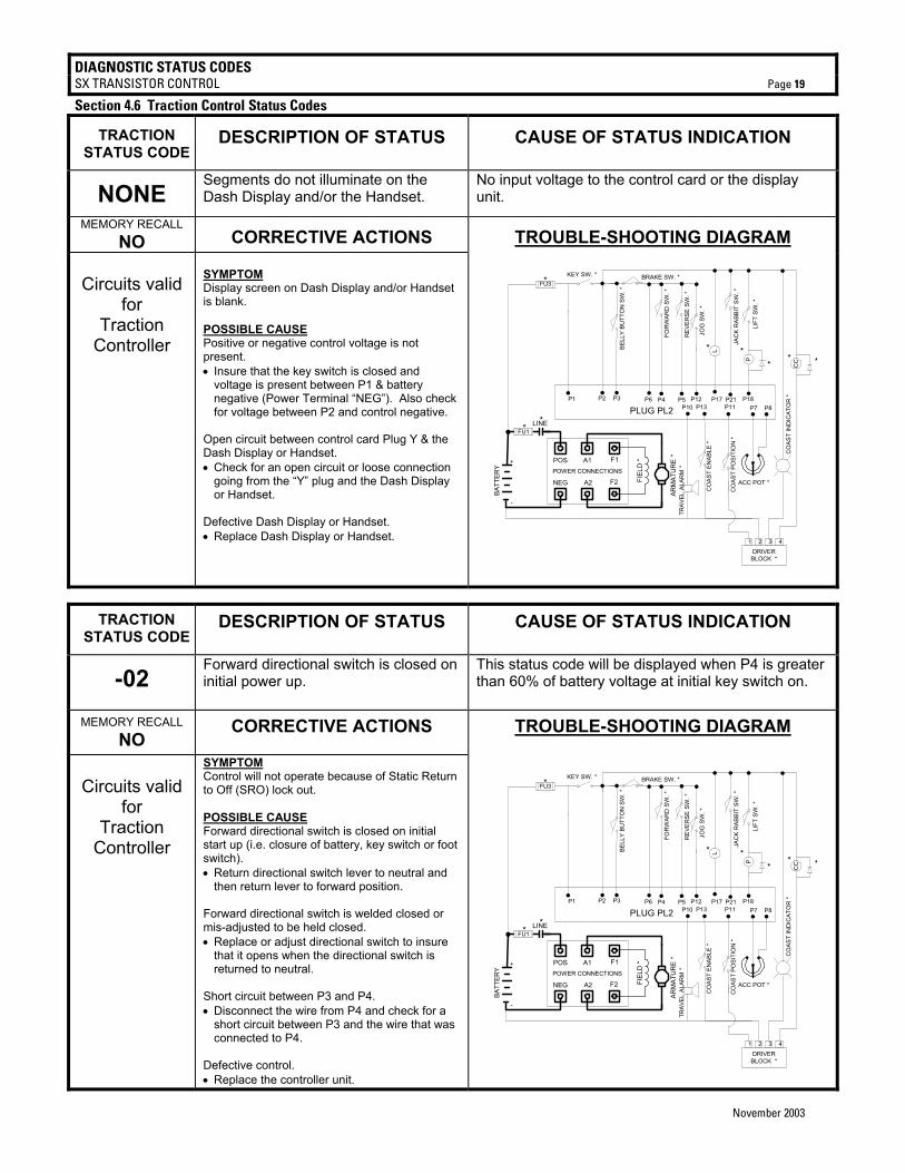
NONE Segments do not illuminate on the Dash Display and/or the Handset.
No input voltage to the control card or the display unit.
MEMORY RECALL NO CORRECTIVE ACTIONS TROUBLE-SHOOTING DIAGRAM
Circuits valid
for Traction
Controller
SYMPTOM Display screen on Dash Display and/or Handset is blank. POSSIBLE CAUSE Positive or negative control voltage is not present. • Insure that the key switch is closed and
voltage is present between P1 & battery negative (Power Terminal “NEG”). Also check for voltage between P2 and control negative.
Open circuit between control card Plug Y & the Dash Display or Handset. • Check for an open circuit or loose connection
going from the “Y” plug and the Dash Display or Handset.
Defective Dash Display or Handset. • Replace Dash Display or Handset.
ARM
ATU
RE
*
KEY SW. *
P2 P4 P5
BRAKE SW. *
P17P3
LBELL
Y BU
TTO
N S
W. *
JAC
K R
ABBI
T S
W. *
P21P12
JOG
SW
. *
P6
PLUG PL2P18
LIFT
SW
. *
P13
FOR
WAR
D S
W. *
REV
ERSE
SW
. *
CO
AST
ENAB
LE *
POWER CONNECTIONS
POS A1 F1
NEG A2 F2 FIEL
D *
P7 P8
ACC POT *
TRAV
EL A
LAR
M *
P10
DRIVERBLOCK *
1 2 3 4
CO
AST
POSI
TIO
N *
P11
+
-
P1
LINE
BATT
ERY
P
CC **
**
CO
AST
IND
ICAT
OR
*
*
FU1
FU3*
**
TRACTION STATUS CODE
DESCRIPTION OF STATUS CAUSE OF STATUS INDICATION
-02 Forward directional switch is closed on initial power up.
This status code will be displayed when P4 is greater than 60% of battery voltage at initial key switch on.
MEMORY RECALL NO CORRECTIVE ACTIONS TROUBLE-SHOOTING DIAGRAM
Circuits valid
for Traction
Controller
SYMPTOM Control will not operate because of Static Return to Off (SRO) lock out. POSSIBLE CAUSE Forward directional switch is closed on initial start up (i.e. closure of battery, key switch or foot switch). • Return directional switch lever to neutral and
then return lever to forward position. Forward directional switch is welded closed or mis-adjusted to be held closed. • Replace or adjust directional switch to insure
that it opens when the directional switch is returned to neutral.
Short circuit between P3 and P4. • Disconnect the wire from P4 and check for a
short circuit between P3 and the wire that was connected to P4.
Defective control. • Replace the controller unit.
ARM
ATU
RE
*
KEY SW. *
P2 P4 P5
BRAKE SW. *
P17P3
LBELL
Y BU
TTO
N S
W. *
JAC
K R
ABBI
T SW
. *
P21P12
JOG
SW
. *
P6
PLUG PL2P18
LIFT
SW
. *
P13
FOR
WAR
D S
W. *
REV
ERSE
SW
. *
CO
AST
ENAB
LE *
POWER CONNECTIONS
POS A1 F1
NEG A2 F2 FIEL
D *
P7 P8
ACC POT *
TRAV
EL A
LAR
M *
P10
DRIVERBLOCK *
1 2 3 4
CO
AST
POSI
TIO
N *
P11
+
-
P1
LINE
BATT
ERY
P
CC **
**
CO
AST
IND
ICAT
OR
*
*
FU1
FU3*
**
DIAGNOSTIC STATUS CODES SX TRANSISTOR CONTROL Page 20
November 2003
TRACTION
STATUS CODE DESCRIPTION OF STATUS CAUSE OF STATUS INDICATION
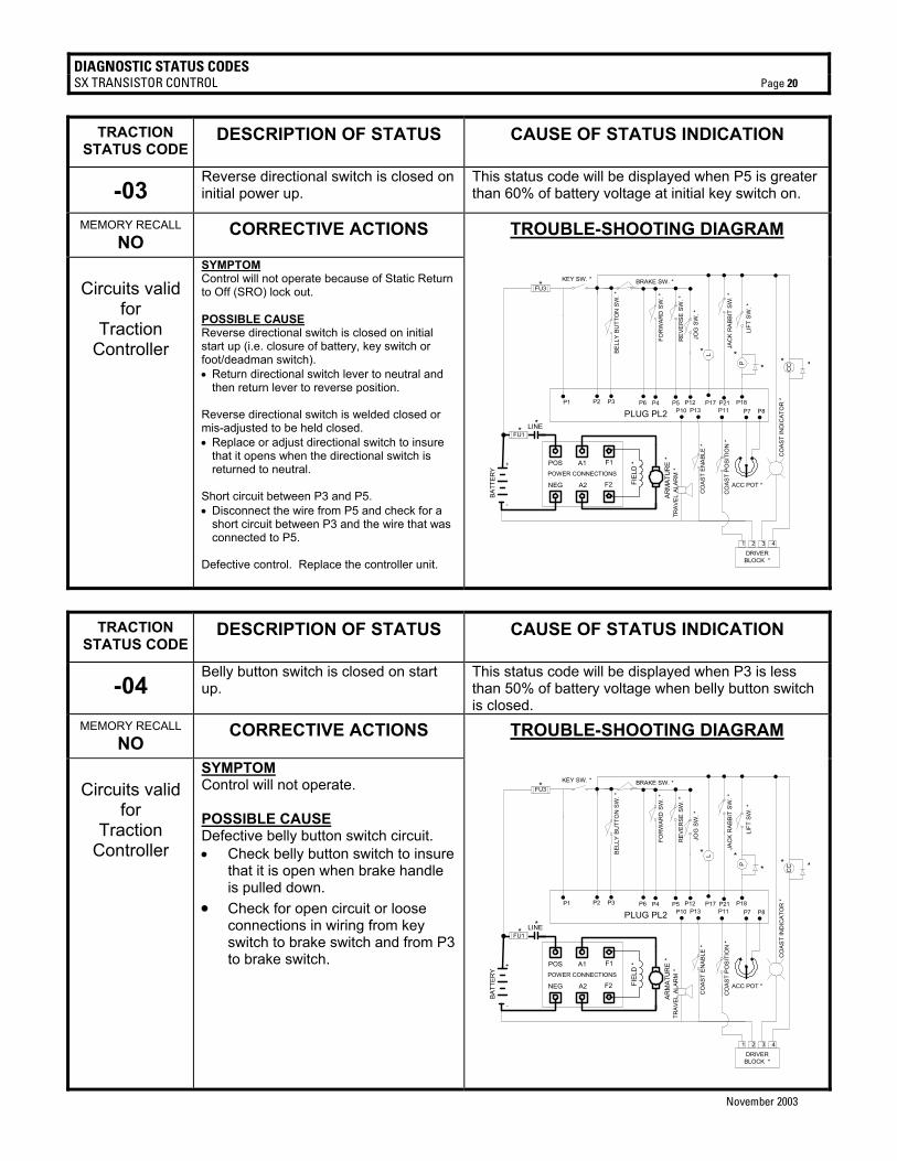
-03 Reverse directional switch is closed on initial power up.
This status code will be displayed when P5 is greater than 60% of battery voltage at initial key switch on.
MEMORY RECALL NO CORRECTIVE ACTIONS TROUBLE-SHOOTING DIAGRAM
Circuits valid
for Traction
Controller
SYMPTOM Control will not operate because of Static Return to Off (SRO) lock out. POSSIBLE CAUSE Reverse directional switch is closed on initial start up (i.e. closure of battery, key switch or foot/deadman switch). • Return directional switch lever to neutral and
then return lever to reverse position. Reverse directional switch is welded closed or mis-adjusted to be held closed. • Replace or adjust directional switch to insure
that it opens when the directional switch is returned to neutral.
Short circuit between P3 and P5. • Disconnect the wire from P5 and check for a
short circuit between P3 and the wire that was connected to P5.
Defective control. Replace the controller unit.
ARM
ATU
RE
*
KEY SW. *
P2 P4 P5
BRAKE SW. *
P17P3
LBELL
Y BU
TTO
N S
W. *
JAC
K R
ABBI
T S
W. *
P21P12
JOG
SW
. *
P6
PLUG PL2P18
LIFT
SW
. *
P13
FOR
WAR
D S
W. *
REV
ERSE
SW
. *
CO
AST
ENAB
LE *
POWER CONNECTIONS
POS A1 F1
NEG A2 F2 FIEL
D *
P7 P8
ACC POT *
TRAV
EL A
LAR
M *
P10
DRIVERBLOCK *
1 2 3 4
CO
AST
POSI
TIO
N *
P11
+
-
P1
LINE
BATT
ERY
P
CC **
**
CO
AST
IND
ICAT
OR
*
*
FU1
FU3*
**
TRACTION STATUS CODE
DESCRIPTION OF STATUS CAUSE OF STATUS INDICATION
-04 Belly button switch is closed on start up.
This status code will be displayed when P3 is less than 50% of battery voltage when belly button switch is closed.
MEMORY RECALL NO CORRECTIVE ACTIONS TROUBLE-SHOOTING DIAGRAM
Circuits valid
for Traction
Controller
SYMPTOM Control will not operate. POSSIBLE CAUSE Defective belly button switch circuit. • Check belly button switch to insure
that it is open when brake handle is pulled down.
• Check for open circuit or loose connections in wiring from key switch to brake switch and from P3 to brake switch.
ARM
ATU
RE
*
KEY SW. *
P2 P4 P5
BRAKE SW. *
P17P3
LBELL
Y BU
TTO
N S
W. *
JAC
K R
ABBI
T SW
. *
P21P12
JOG
SW
. *
P6
PLUG PL2P18
LIFT
SW
. *
P13
FOR
WAR
D S
W. *
REV
ERSE
SW
. *
CO
AST
ENAB
LE *
POWER CONNECTIONS
POS A1 F1
NEG A2 F2 FIEL
D *
P7 P8
ACC POT *
TRAV
EL A
LAR
M *
P10
DRIVERBLOCK *
1 2 3 4
CO
AST
POSI
TIO
N *
P11
+
-
P1
LINE
BATT
ERY
P
CC **
**
CO
AST
IND
ICAT
OR
*
*
FU1
FU3*
**
DIAGNOSTIC STATUS CODES SX TRANSISTOR CONTROL Page 21
November 2003
TRACTION
STATUS CODE DESCRIPTION OF STATUS CAUSE OF STATUS INDICATION
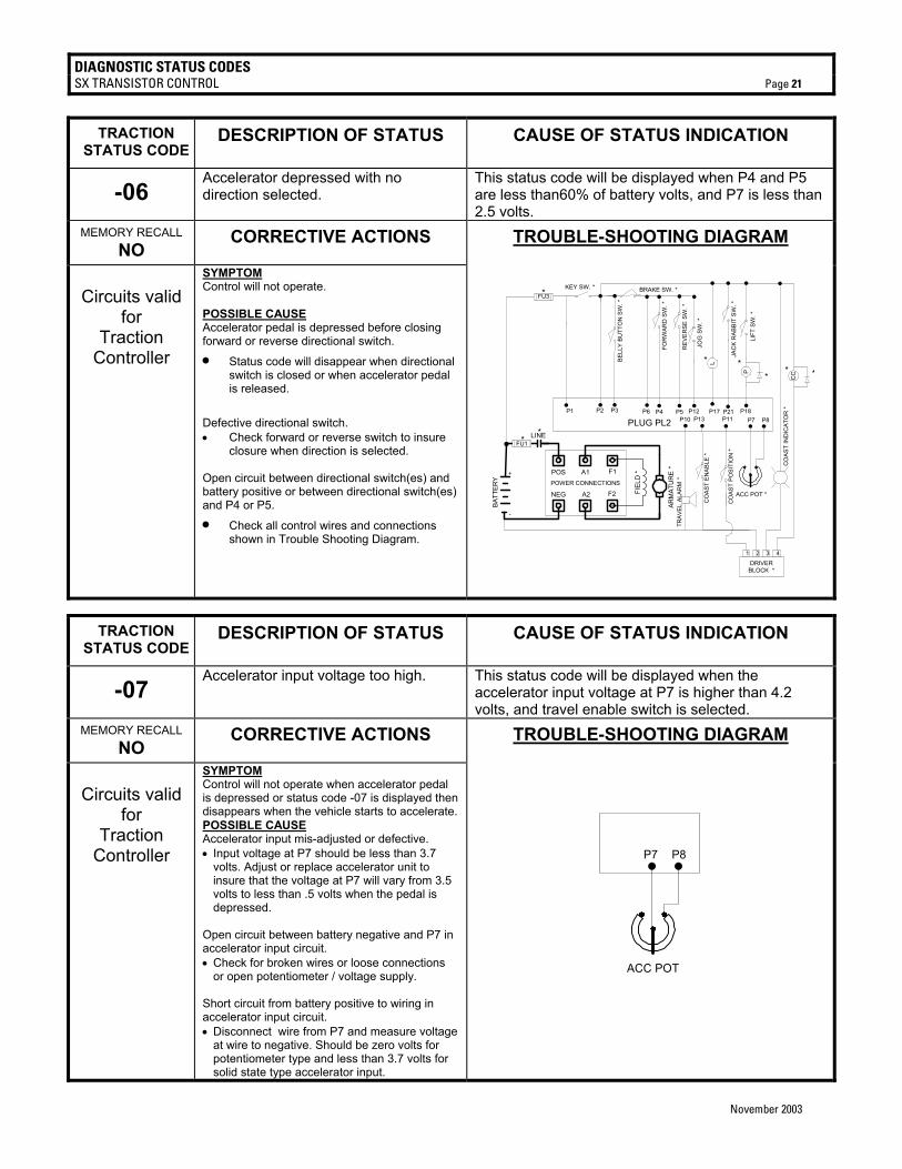
-06 Accelerator depressed with no direction selected.
This status code will be displayed when P4 and P5 are less than60% of battery volts, and P7 is less than 2.5 volts.
MEMORY RECALL NO CORRECTIVE ACTIONS TROUBLE-SHOOTING DIAGRAM
Circuits valid
for Traction
Controller
SYMPTOM Control will not operate. POSSIBLE CAUSE Accelerator pedal is depressed before closing forward or reverse directional switch.
• Status code will disappear when directional switch is closed or when accelerator pedal is released.
Defective directional switch. • Check forward or reverse switch to insure
closure when direction is selected. Open circuit between directional switch(es) and battery positive or between directional switch(es) and P4 or P5.
• Check all control wires and connections shown in Trouble Shooting Diagram.
ARM
ATU
RE
*
KEY SW. *
P2 P4 P5
BRAKE SW. *
P17P3
LBELL
Y BU
TTO
N S
W. *
JAC
K R
ABBI
T S
W. *
P21P12
JOG
SW
. *
P6
PLUG PL2P18
LIFT
SW
. *
P13
FOR
WAR
D S
W. *
REV
ERSE
SW
. *
CO
AST
ENAB
LE *
POWER CONNECTIONS
POS A1 F1
NEG A2 F2 FIEL
D *
P7 P8
ACC POT *
TRAV
EL A
LAR
M *
P10
DRIVERBLOCK *
1 2 3 4
CO
AST
POSI
TIO
N *
P11
+
-
P1
LINE
BATT
ERY
P
CC **
**
CO
AST
IND
ICAT
OR
*
*
FU1
FU3*
**
TRACTION STATUS CODE
DESCRIPTION OF STATUS CAUSE OF STATUS INDICATION
-07 Accelerator input voltage too high. This status code will be displayed when the
accelerator input voltage at P7 is higher than 4.2 volts, and travel enable switch is selected.
MEMORY RECALL NO CORRECTIVE ACTIONS TROUBLE-SHOOTING DIAGRAM
Circuits valid
for Traction
Controller
SYMPTOM Control will not operate when accelerator pedal is depressed or status code -07 is displayed then disappears when the vehicle starts to accelerate. POSSIBLE CAUSE Accelerator input mis-adjusted or defective. • Input voltage at P7 should be less than 3.7
volts. Adjust or replace accelerator unit to insure that the voltage at P7 will vary from 3.5 volts to less than .5 volts when the pedal is depressed.
Open circuit between battery negative and P7 in accelerator input circuit. • Check for broken wires or loose connections
or open potentiometer / voltage supply. Short circuit from battery positive to wiring in accelerator input circuit. • Disconnect wire from P7 and measure voltage
at wire to negative. Should be zero volts for potentiometer type and less than 3.7 volts for solid state type accelerator input.
P7 P8
ACC POT
DIAGNOSTIC STATUS CODES SX TRANSISTOR CONTROL Page 22
November 2003
TRACTION
STATUS CODE DESCRIPTION OF STATUS CAUSE OF STATUS INDICATION
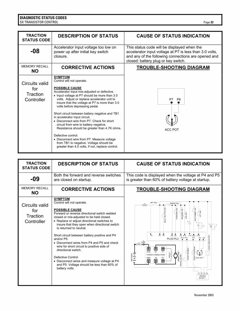
-08 Accelerator input voltage too low on power up after initial key switch closure.
This status code will be displayed when the accelerator input voltage at P7 is less than 3.0 volts, and any of the following connections are opened and closed: battery plug or key switch.
MEMORY RECALL NO CORRECTIVE ACTIONS TROUBLE-SHOOTING DIAGRAM
Circuits valid
for Traction
Controller
SYMPTOM Control will not operate. POSSIBLE CAUSE Accelerator input mis-adjusted or defective. • Input voltage at P7 should be more than 3.0
volts. Adjust or replace accelerator unit to insure that the voltage at P7 is more than 3.0 volts before depressing pedal.
Short circuit between battery negative and TB1 in accelerator input circuit. • Disconnect wire from P7. Check for short
circuit from wire to battery negative. Resistance should be greater than 4.7K ohms.
Defective control. • Disconnect wire from P7. Measure voltage
from TB1 to negative. Voltage should be greater than 4.5 volts, if not, replace control.
P7 P8
ACC POT
TRACTION
STATUS CODE DESCRIPTION OF STATUS CAUSE OF STATUS INDICATION
-09 Both the forward and reverse switches are closed on startup.
This code is displayed when the voltage at P4 and P5 is greater than 60% of battery voltage at startup.
MEMORY RECALL NO CORRECTIVE ACTIONS TROUBLE-SHOOTING DIAGRAM
Circuits valid
for Traction
Controller
SYMPTOM Control will not operate. POSSIBLE CAUSE Forward or reverse directional switch welded closed or mis-adjusted to be held closed. • Replace or adjust directional switches to
insure that they open when directional switch is returned to neutral.
Short circuit between battery positive and P4 and/or P5. • Disconnect wires from P4 and P5 and check
wire for short circuit to positive side of directional switch.
Defective Control • Disconnect wires and measure voltage at P4
and P5. Voltage should be less than 60% of battery volts.
ARM
ATU
RE
*
KEY SW. *
P2 P4 P5
BRAKE SW. *
P17P3
LBELL
Y BU
TTO
N S
W. *
JAC
K R
ABBI
T SW
. *
P21P12
JOG
SW
. *
P6
PLUG PL2P18
LIFT
SW
. *
P13
FOR
WAR
D S
W. *
REV
ERSE
SW
. *
CO
AST
ENAB
LE *
POWER CONNECTIONS
POS A1 F1
NEG A2 F2 FIEL
D *
P7 P8
ACC POT *
TRAV
EL A
LAR
M *
P10
DRIVERBLOCK *
1 2 3 4
CO
AST
POSI
TIO
N *
P11
+
-
P1
LINE
BATT
ERY
P
CC **
**
CO
AST
IND
ICAT
OR
*
*
FU1
FU3*
**
DIAGNOSTIC STATUS CODES SX TRANSISTOR CONTROL Page 23
November 2003
TRACTION STATUS CODE
DESCRIPTION OF STATUS CAUSE OF STATUS INDICATION
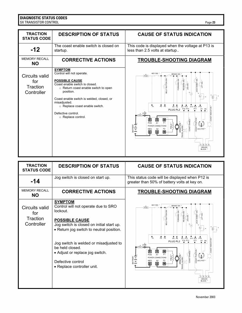
-12 The coast enable switch is closed on startup.
This code is displayed when the voltage at P13 is less than 2.5 volts at startup..
MEMORY RECALL NO CORRECTIVE ACTIONS TROUBLE-SHOOTING DIAGRAM
Circuits valid
for Traction
Controller
SYMPTOM Control will not operate. POSSIBLE CAUSE Coast enable switch is closed.
o Return coast enable switch to open position.
Coast enable switch is welded, closed, or misadjusted.
o Replace coast enable switch. Defective control.
o Replace control.
ARM
ATU
RE
*
KEY SW. *
P2 P4 P5
BRAKE SW. *
P17P3
LBELL
Y BU
TTO
N S
W. *
JAC
K R
ABBI
T SW
. *
P21P12
JOG
SW
. *
P6
PLUG PL2P18
LIFT
SW
. *
P13
FOR
WAR
D S
W. *
REV
ERSE
SW
. *
CO
AST
ENAB
LE *
POWER CONNECTIONS
POS A1 F1
NEG A2 F2 FIEL
D *
P7 P8
ACC POT *
TRAV
EL A
LAR
M *
P10
DRIVERBLOCK *
1 2 3 4
CO
AST
POSI
TIO
N *
P11
+
-
P1
LINE
BATT
ERY
P
CC **
**
CO
AST
IND
ICAT
OR
*
*
FU1
FU3*
**
TRACTION STATUS CODE
DESCRIPTION OF STATUS CAUSE OF STATUS INDICATION
-14 Jog switch is closed on start up. This status code will be displayed when P12 is
greater than 50% of battery volts at key on.
MEMORY RECALL NO CORRECTIVE ACTIONS TROUBLE-SHOOTING DIAGRAM
Circuits valid
for Traction
Controller
SYMPTOM Control will not operate due to SRO lockout. POSSIBLE CAUSE Jog switch is closed on initial start up. • Return jog switch to neutral position.
Jog switch is welded or misadjusted to be held closed. • Adjust or replace jog switch. Defective control • Replace controller unit.
ARM
ATU
RE
*
KEY SW. *
P2 P4 P5
BRAKE SW. *
P17P3
LBELL
Y BU
TTO
N S
W. *
JAC
K R
ABBI
T SW
. *
P21P12
JOG
SW
. *
P6
PLUG PL2P18
LIFT
SW
. *
P13
FOR
WAR
D S
W. *
REV
ERSE
SW
. *
CO
AST
ENAB
LE *
POWER CONNECTIONS
POS A1 F1
NEG A2 F2 FIEL
D *
P7 P8
ACC POT *
TRAV
EL A
LAR
M *
P10
DRIVERBLOCK *
1 2 3 4
CO
AST
POSI
TIO
N *
P11
+
-
P1
LINE
BATT
ERY
P
CC **
**
CO
AST
IND
ICAT
OR
*
*
FU1
FU3*
**
DIAGNOSTIC STATUS CODES SX TRANSISTOR CONTROL Page 24
November 2003
TRACTION STATUS CODE
DESCRIPTION OF STATUS CAUSE OF STATUS INDICATION
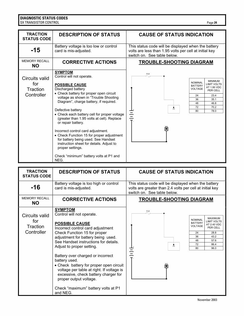
-15 Battery voltage is too low or control card is mis-adjusted.
This status code will be displayed when the battery volts are less than 1.95 volts per cell at initial key switch on. See table below.
MEMORY RECALL NO CORRECTIVE ACTIONS TROUBLE-SHOOTING DIAGRAM
Circuits valid
for Traction
Controller
SYMPTOM Control will not operate. POSSIBLE CAUSE Discharged battery • Check battery for proper open circuit
voltage as shown in “Trouble Shooting Diagram”, charge battery, if required.
Defective battery • Check each battery cell for proper voltage
(greater than 1.95 volts at cell). Replace or repair battery.
Incorrect control card adjustment. • Check Function 15 for proper adjustment
for battery being used. See Handset instruction sheet for details. Adjust to proper settings.
Check “minimum” battery volts at P1 and NEG.
NEG
+
-
FU3
P1
NOMINALBATTERYVOLTAGE
MINIMUMLIMIT VOLTSAT 1.95 VDCPER CELL
24
80
4872
3623.4
78.0
46.870.2
35.1
TRACTION STATUS CODE
DESCRIPTION OF STATUS CAUSE OF STATUS INDICATION
-16 Battery voltage is too high or control card is mis-adjusted.
This status code will be displayed when the battery volts are greater than 2.4 volts per cell at initial key switch on. See table below.
MEMORY RECALL NO CORRECTIVE ACTIONS TROUBLE-SHOOTING DIAGRAM
Circuits valid
for Traction
Controller
SYMPTOM Control will not operate. POSSIBLE CAUSE Incorrect control card adjustment Check Function 15 for proper adjustment for battery being used. See Handset instructions for details. Adjust to proper setting. Battery over charged or incorrect battery used. • Check battery for proper open circuit
voltage per table at right. If voltage is excessive, check battery charger for proper output voltage.
Check “maximum” battery volts at P1 and NEG.
NEG
+
-
FU3
P1
NOMINALBATTERYVOLTAGE
MAXIMUMLIMIT VOLTSAT 2.40 VDCPER CELL
24
80
4872
3628.8
96.0
57.686.4
43.2
DIAGNOSTIC STATUS CODES SX TRANSISTOR CONTROL Page 25
November 2003
TRACTION STATUS CODE
DESCRIPTION OF STATUS CAUSE OF STATUS INDICATION
-23 Motor field current is high on start up in the reverse direction.
This status code will be displayed when the control sees approximately 1 amp of field current on startup in the reverse direction.
MEMORY RECALL NO CORRECTIVE ACTIONS TROUBLE-SHOOTING DIAGRAM
Circuits valid
for Traction
Controller
SYMPTOM Control will not operate. POSSIBLE CAUSE Defective motor or the motor F1 or F2 cables are pinched to the motor frame. • Remove the F1 and F2 cable
connections at the control. If the code disappears, check motor and cables for defect or short.
Defective control. • Replace controller unit if the code
does not disappear after the F1 and F2 connections are removed at the control.
NO GRAPHIC FOR THIS STATUS CODE
TRACTION STATUS CODE
DESCRIPTION OF STATUS CAUSE OF STATUS INDICATION
-24 Motor field current is high on start up in the forward direction.
This status code will be displayed when the control sees approximately 1 amp of field current on startup in the reverse direction.
MEMORY RECALL NO CORRECTIVE ACTIONS TROUBLE-SHOOTING DIAGRAM
Circuits valid
for Traction
Controller
SYMPTOM Control will not operate. POSSIBLE CAUSE Defective motor or the motor F1 or F2 cables are pinched to the motor frame. • Remove the F1 and F2 cable
connections at the control. If the code disappears, check motor and cables for defect or short.
Defective control. • Replace controller unit if the code
does not disappear after the F1 and F2 connections are removed at the control.
NO GRAPHIC FOR THIS STATUS CODE
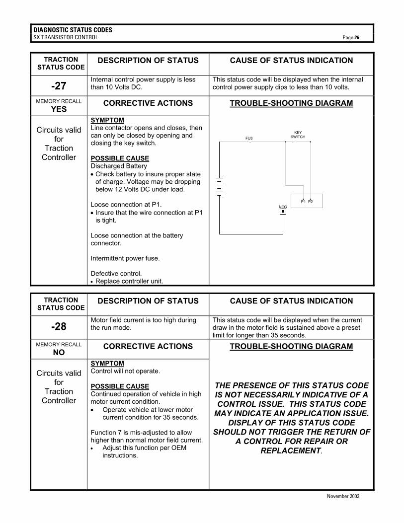
DIAGNOSTIC STATUS CODES SX TRANSISTOR CONTROL Page 26
November 2003
TRACTION
STATUS CODE DESCRIPTION OF STATUS CAUSE OF STATUS INDICATION
-27 Internal control power supply is less than 10 Volts DC.
This status code will be displayed when the internal control power supply dips to less than 10 volts.
MEMORY RECALL YES CORRECTIVE ACTIONS TROUBLE-SHOOTING DIAGRAM
Circuits valid
for Traction
Controller
SYMPTOM Line contactor opens and closes, then can only be closed by opening and closing the key switch. POSSIBLE CAUSE Discharged Battery • Check battery to insure proper state
of charge. Voltage may be dropping below 12 Volts DC under load.
Loose connection at P1. • Insure that the wire connection at P1
is tight. Loose connection at the battery connector. Intermittent power fuse. Defective control. • Replace controller unit.
NEG
+
-
FU3KEY
SWITCH
P1 P2
TRACTION STATUS CODE
DESCRIPTION OF STATUS CAUSE OF STATUS INDICATION
-28 Motor field current is too high during the run mode.
This status code will be displayed when the current draw in the motor field is sustained above a preset limit for longer than 35 seconds.
MEMORY RECALL NO CORRECTIVE ACTIONS TROUBLE-SHOOTING DIAGRAM
Circuits valid
for Traction
Controller
SYMPTOM Control will not operate. POSSIBLE CAUSE Continued operation of vehicle in high motor current condition. • Operate vehicle at lower motor
current condition for 35 seconds. Function 7 is mis-adjusted to allow higher than normal motor field current. • Adjust this function per OEM
instructions.
THE PRESENCE OF THIS STATUS CODE IS NOT NECESSARILY INDICATIVE OF A CONTROL ISSUE. THIS STATUS CODE
MAY INDICATE AN APPLICATION ISSUE. DISPLAY OF THIS STATUS CODE
SHOULD NOT TRIGGER THE RETURN OF A CONTROL FOR REPAIR OR
REPLACEMENT.
DIAGNOSTIC STATUS CODES SX TRANSISTOR CONTROL Page 27
November 2003
TRACTION
STATUS CODE DESCRIPTION OF STATUS CAUSE OF STATUS INDICATION
-41 Open thermal protector (TP) or transistor over temperature.
This status code will be displayed when the voltage at the thermal protector is too high.
MEMORY RECALL YES CORRECTIVE ACTIONS TROUBLE-SHOOTING DIAGRAM
Circuits valid
for Traction
Controller
SYMPTOM Reduced or no power to traction motor in control range. POSSIBLE CAUSE Control is in thermal cut-back. • Allow control to cool, status code
should disappear. • Insufficient heat transfer may be
occurring between control and mounting surface.
THE PRESENCE OF THIS STATUS CODE IS NOT NECESSARILY INDICATIVE OF A CONTROL ISSUE. THIS STATUS CODE
MAY INDICATE AN APPLICATION ISSUE. DISPLAY OF THIS STATUS CODE
SHOULD NOT TRIGGER THE RETURN OF A CONTROL FOR REPAIR OR
REPLACEMENT.
TRACTION STATUS CODE
DESCRIPTION OF STATUS CAUSE OF STATUS INDICATION
-42 Motor armature offset voltage is too high.
This status code will be displayed when the voltage at the internal control current sensor input is greater than 2.6 volts with no current flowing in the motor circuit.
MEMORY RECALL NO CORRECTIVE ACTIONS TROUBLE-SHOOTING DIAGRAM
Circuits valid
for Traction
Controller
SYMPTOM Control will not operate. POSSIBLE CAUSE Check for loose connection at the A1 terminal of the control. This can cause excessive heating of the internal armature current sensor which will lead to the display of the status code. Defective control. • Replace controller unit.
NO GRAPHIC FOR THIS STATUS CODE
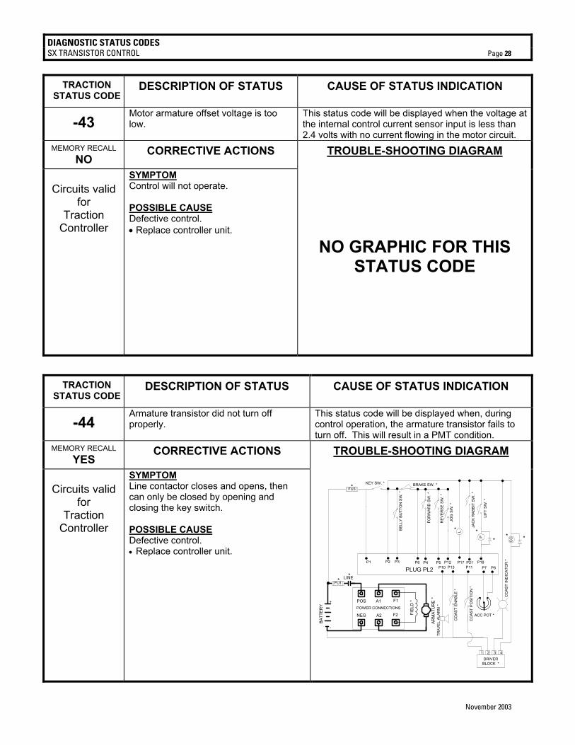
DIAGNOSTIC STATUS CODES SX TRANSISTOR CONTROL Page 28
November 2003
TRACTION
STATUS CODE DESCRIPTION OF STATUS CAUSE OF STATUS INDICATION
-43 Motor armature offset voltage is too low.
This status code will be displayed when the voltage at the internal control current sensor input is less than 2.4 volts with no current flowing in the motor circuit.
MEMORY RECALL NO CORRECTIVE ACTIONS TROUBLE-SHOOTING DIAGRAM
Circuits valid
for Traction
Controller
SYMPTOM Control will not operate. POSSIBLE CAUSE Defective control. • Replace controller unit.
NO GRAPHIC FOR THIS STATUS CODE
TRACTION STATUS CODE
DESCRIPTION OF STATUS CAUSE OF STATUS INDICATION
-44 Armature transistor did not turn off properly.
This status code will be displayed when, during control operation, the armature transistor fails to turn off. This will result in a PMT condition.
MEMORY RECALL YES CORRECTIVE ACTIONS TROUBLE-SHOOTING DIAGRAM
Circuits valid
for Traction
Controller
SYMPTOM Line contactor closes and opens, then can only be closed by opening and closing the key switch. POSSIBLE CAUSE Defective control. • Replace controller unit.
ARM
ATU
RE
*
KEY SW. *
P2 P4 P5
BRAKE SW. *
P17P3
LBELL
Y BU
TTO
N S
W. *
JAC
K R
ABBI
T SW
. *
P21P12
JOG
SW
. *
P6
PLUG PL2P18
LIFT
SW
. *
P13
FOR
WAR
D S
W. *
REV
ERSE
SW
. *
CO
AST
ENAB
LE *
POWER CONNECTIONS
POS A1 F1
NEG A2 F2 FIEL
D *
P7 P8
ACC POT *
TRAV
EL A
LAR
M *
P10
DRIVERBLOCK *
1 2 3 4
CO
AST
POSI
TIO
N *
P11
+
-
P1
LINE
BATT
ERY
P
CC **
**
CO
AST
IND
ICAT
OR
*
*
FU1
FU3*
**

DIAGNOSTIC STATUS CODES SX TRANSISTOR CONTROL Page 29
November 2003
TRACTION STATUS CODE
DESCRIPTION OF STATUS CAUSE OF STATUS INDICATION
-45 Armature transistor did not turn on properly.
This status code will be displayed when, during control operation, the armature transistor fails to turn on properly. This will result in a PMT condition.
MEMORY RECALL YES CORRECTIVE ACTIONS TROUBLE-SHOOTING DIAGRAM
Circuits valid
for Traction
Controller
SYMPTOM Line contactor closes and opens, then can only be closed by opening and closing the key switch. POSSIBLE CAUSE Defective control. • Replace controller unit.
ARM
ATU
RE
*
KEY SW. *
P2 P4 P5
BRAKE SW. *
P17P3
LBELL
Y BU
TTO
N S
W. *
JAC
K R
ABBI
T S
W. *
P21P12
JOG
SW
. *
P6
PLUG PL2P18
LIFT
SW
. *
P13
FOR
WAR
D S
W. *
REV
ERSE
SW
. *
CO
AST
ENAB
LE *
POWER CONNECTIONS
POS A1 F1
NEG A2 F2 FIEL
D *
P7 P8
ACC POT *
TRAV
EL A
LAR
M *
P10
DRIVERBLOCK *
1 2 3 4
CO
AST
POSI
TIO
N *
P11
+
-
P1
LINE
BATT
ERY
P
CC **
**
CO
AST
IND
ICAT
OR
*
*
FU1
FU3*
**
TRACTION STATUS CODE
DESCRIPTION OF STATUS CAUSE OF STATUS INDICATION
-46 “Look Ahead” test for A2 volts less than 12% of battery volts.
This status code will be displayed when the voltage at A2 is less than 12% of battery volts.
MEMORY RECALL NO CORRECTIVE ACTIONS TROUBLE-SHOOTING DIAGRAM
Circuits valid
for Traction
Controller
SYMPTOM Line contactor will not pick up. POSSIBLE CAUSE Check for short circuit from the motor armature to the frame of the vehicle.
ARM
ATU
RE
*
KEY SW. *
P2 P4 P5
BRAKE SW. *
P17P3
LBELL
Y BU
TTO
N S
W. *
JAC
K R
ABBI
T SW
. *
P21P12
JOG
SW
. *
P6
PLUG PL2P18
LIFT
SW
. *
P13
FOR
WAR
D S
W. *
REV
ERSE
SW
. *
CO
AST
ENAB
LE *
POWER CONNECTIONS
POS A1 F1
NEG A2 F2 FIEL
D *
P7 P8
ACC POT *
TRAV
EL A
LAR
M *
P10
DRIVERBLOCK *
1 2 3 4
CO
AST
POSI
TIO
N *
P11
+
-
P1
LINE
BATT
ERY
P
CC **
**
CO
AST
IND
ICAT
OR
*
*
FU1
FU3*
**

DIAGNOSTIC STATUS CODES SX TRANSISTOR CONTROL Page 30
November 2003
TRACTION STATUS CODE
DESCRIPTION OF STATUS CAUSE OF STATUS INDICATION
-49 Motor field current is too low during the run mode.
This status code will be displayed when the current draw in the motor field is too low during the run mode.
MEMORY RECALL NO CORRECTIVE ACTIONS TROUBLE-SHOOTING DIAGRAM
Circuits valid
for Traction
Controller
SYMPTOM Control will only operate for a second or two before shutting down. POSSIBLE CAUSE If the fault code is intermittent, verify that the accelerator pot is adjusted correctly. Check for open motor field coils or loose or intermittent field connections, or open F1 or F2 connections.
ARM
ATU
RE
*
KEY SW. *
P2 P4 P5
BRAKE SW. *
P17P3
LBELL
Y BU
TTO
N S
W. *
JAC
K R
ABBI
T SW
. *
P21P12
JOG
SW
. *
P6
PLUG PL2P18
LIFT
SW
. *
P13
FOR
WAR
D S
W. *
REV
ERSE
SW
. *
CO
AST
ENAB
LE *
POWER CONNECTIONS
POS A1 F1
NEG A2 F2 FIEL
D *
P7 P8
ACC POT *
TRAV
EL A
LAR
M *
P10
DRIVERBLOCK *
1 2 3 4
CO
AST
POSI
TIO
N *
P11
+
-
P1
LINE
BATT
ERY
P
CC **
**
CO
AST
IND
ICAT
OR
*
*
FU1
FU3*
**
TRACTION STATUS CODE
DESCRIPTION OF STATUS CAUSE OF STATUS INDICATION
-51 Capacitor volts are low before the line contactor closes.
This status code will be displayed during “key on” when the voltage at the positive connection is less than 75% of battery volts at initial key switch on.
MEMORY RECALL NO CORRECTIVE ACTIONS TROUBLE-SHOOTING DIAGRAM
Circuits valid
for Traction
Controller
SYMPTOM Line contactor does not close when capacitor does not precharge. POSSIBLE CAUSE Possible motor leakage to frame – usually at the internal brush connections. Defective control fuse. • Check control fuse for open circuit.
Replace fuse, if necessary. Loose connector at P1. Verify that no external load has been added to the low side of the line contactor.
ARM
ATU
RE
*
KEY SW. *
P2 P4 P5
BRAKE SW. *
P17P3
LBELL
Y BU
TTO
N S
W. *
JAC
K R
ABBI
T SW
. *
P21P12
JOG
SW
. *
P6
PLUG PL2P18
LIFT
SW
. *
P13
FOR
WAR
D S
W. *
REV
ERSE
SW
. *
CO
AST
ENAB
LE *
POWER CONNECTIONS
POS A1 F1
NEG A2 F2 FIEL
D *
P7 P8
ACC POT *
TRAV
EL A
LAR
M *
P10
DRIVERBLOCK *
1 2 3 4
CO
AST
POSI
TIO
N *
P11
+
-
P1
LINE
BATT
ERY
P
CC **
**
CO
AST
IND
ICAT
OR
*
*
FU1
FU3*
**

DIAGNOSTIC STATUS CODES SX TRANSISTOR CONTROL Page 31
November 2003
TRACTION
STATUS CODE DESCRIPTION OF STATUS CAUSE OF STATUS INDICATION
-57 Controller “motor current sensor” input too low during running.
This status code will be displayed when the voltage input from the current sensor is too low during running.
MEMORY RECALL YES CORRECTIVE ACTIONS TROUBLE-SHOOTING DIAGRAM
Circuits valid
for Traction
Controller
SYMPTOM Control will not operate. POSSIBLE CAUSE Check for loose or intermittent connections at A1 or A2 of the control. Intermittent motor brush connections. Defective control. • Replace controller unit.
NO GRAPHIC FOR THIS STATUS CODE
TRACTION STATUS CODE
DESCRIPTION OF STATUS CAUSE OF STATUS INDICATION
-64 The line driver input (P2-17) is less than 12% of battery volts
This status code will be displayed when the control detects that the line driver input (P2-17) is less than 12% battery volts when the key switch is turned on.
MEMORY RECALL NO CORRECTIVE ACTIONS TROUBLE-SHOOTING DIAGRAM
Circuits valid
for Traction
Controller
SYMPTOM Control will not operate. POSSIBLE CAUSE -Open wire connection to Pin 17 - Shorted line Driver transistor Defective control. • Replace controller unit.
ARM
ATU
RE
*
KEY SW. *
P2 P4 P5
BRAKE SW. *
P17P3
LBELL
Y BU
TTO
N S
W. *
JAC
K R
ABBI
T SW
. *
P21P12
JOG
SW
. *
P6
PLUG PL2P18
LIFT
SW
. *
P13
FOR
WAR
D S
W. *
REV
ERSE
SW
. *
CO
AST
ENAB
LE *
POWER CONNECTIONS
POS A1 F1
NEG A2 F2 FIEL
D *
P7 P8
ACC POT *
TRAV
EL A
LAR
M *
P10
DRIVERBLOCK *
1 2 3 4
CO
AST
POSI
TIO
N *
P11
+
-
P1
LINE
BATT
ERY
P
CC **
**
CO
AST
IND
ICAT
OR
*
*
FU1
FU3*
**
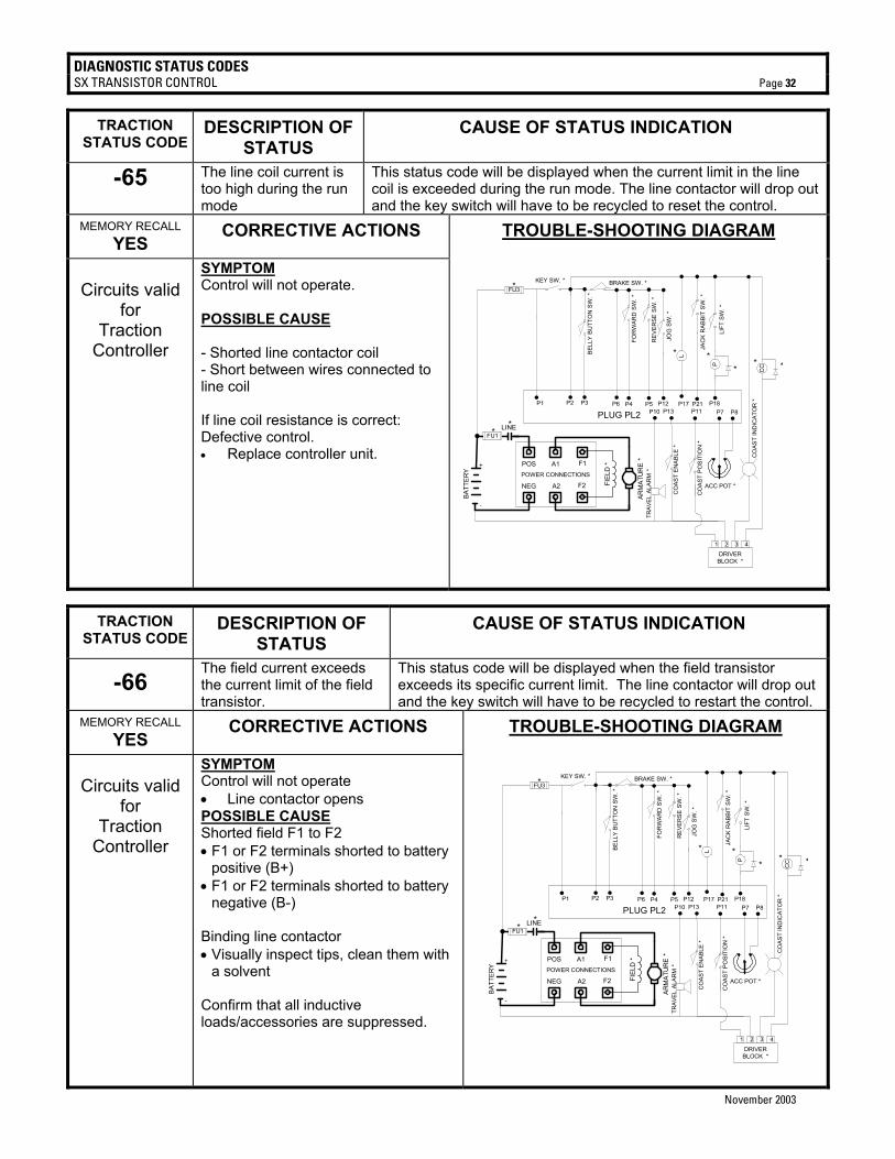
DIAGNOSTIC STATUS CODES SX TRANSISTOR CONTROL Page 32
November 2003
TRACTION STATUS CODE
DESCRIPTION OF STATUS
CAUSE OF STATUS INDICATION
-65 The line coil current is too high during the run mode
This status code will be displayed when the current limit in the line coil is exceeded during the run mode. The line contactor will drop out and the key switch will have to be recycled to reset the control.
MEMORY RECALL YES CORRECTIVE ACTIONS TROUBLE-SHOOTING DIAGRAM
Circuits valid
for Traction
Controller
SYMPTOM Control will not operate. POSSIBLE CAUSE - Shorted line contactor coil - Short between wires connected to line coil If line coil resistance is correct: Defective control. • Replace controller unit.
ARM
ATU
RE
*
KEY SW. *
P2 P4 P5
BRAKE SW. *
P17P3
LBELL
Y BU
TTO
N S
W. *
JAC
K R
ABBI
T S
W. *
P21P12
JOG
SW
. *
P6
PLUG PL2P18
LIFT
SW
. *
P13
FOR
WAR
D S
W. *
REV
ERSE
SW
. *
CO
AST
ENAB
LE *
POWER CONNECTIONS
POS A1 F1
NEG A2 F2 FIEL
D *
P7 P8
ACC POT *
TRAV
EL A
LAR
M *
P10
DRIVERBLOCK *
1 2 3 4
CO
AST
POSI
TIO
N *
P11
+
-
P1
LINE
BATT
ERY
P
CC **
**
CO
AST
IND
ICAT
OR
*
*
FU1
FU3*
**
TRACTION STATUS CODE
DESCRIPTION OF STATUS
CAUSE OF STATUS INDICATION
-66 The field current exceeds the current limit of the field transistor.
This status code will be displayed when the field transistor exceeds its specific current limit. The line contactor will drop out and the key switch will have to be recycled to restart the control.
MEMORY RECALL YES CORRECTIVE ACTIONS TROUBLE-SHOOTING DIAGRAM
Circuits valid
for Traction
Controller
SYMPTOM Control will not operate • Line contactor opens POSSIBLE CAUSE Shorted field F1 to F2 • F1 or F2 terminals shorted to battery
positive (B+) • F1 or F2 terminals shorted to battery
negative (B-) Binding line contactor • Visually inspect tips, clean them with
a solvent Confirm that all inductive loads/accessories are suppressed.
ARM
ATU
RE
*
KEY SW. *
P2 P4 P5
BRAKE SW. *
P17P3
LBEL
LY B
UTT
ON
SW
. *
JAC
K R
ABBI
T S
W. *
P21P12
JOG
SW
. *
P6
PLUG PL2P18
LIFT
SW
. *
P13
FOR
WA
RD
SW
. *
RE
VER
SE S
W. *
CO
AST
ENAB
LE *
POWER CONNECTIONS
POS A1 F1
NEG A2 F2 FIEL
D *
P7 P8
ACC POT *
TRAV
EL A
LAR
M *
P10
DRIVERBLOCK *
1 2 3 4
CO
AST
POSI
TIO
N *
P11
+
-
P1
LINE
BATT
ERY
P
CC **
**
CO
AST
IND
ICAT
OR
*
*
FU1
FU3*
**
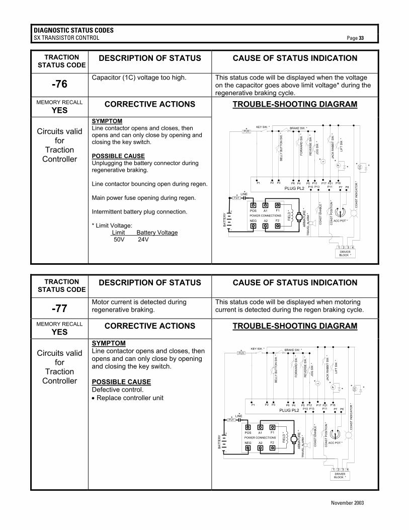
DIAGNOSTIC STATUS CODES SX TRANSISTOR CONTROL Page 33
November 2003
TRACTION STATUS CODE
DESCRIPTION OF STATUS CAUSE OF STATUS INDICATION
-76 Capacitor (1C) voltage too high. This status code will be displayed when the voltage
on the capacitor goes above limit voltage* during the regenerative braking cycle.
MEMORY RECALL YES CORRECTIVE ACTIONS TROUBLE-SHOOTING DIAGRAM
Circuits valid
for Traction
Controller
SYMPTOM Line contactor opens and closes, then opens and can only close by opening and closing the key switch. POSSIBLE CAUSE Unplugging the battery connector during regenerative braking. Line contactor bouncing open during regen. Main power fuse opening during regen. Intermittent battery plug connection. * Limit Voltage: Limit Battery Voltage 50V 24V
ARM
ATU
RE
*
KEY SW. *
P2 P4 P5
BRAKE SW. *
P17P3
LBELL
Y BU
TTO
N S
W. *
JAC
K R
ABB
IT S
W. *
P21P12
JOG
SW
. *
P6
PLUG PL2P18
LIFT
SW
. *
P13
FOR
WAR
D S
W. *
REV
ER
SE S
W. *
CO
AST
ENAB
LE *
POWER CONNECTIONS
POS A1 F1
NEG A2 F2 FIEL
D *
P7 P8
ACC POT *
TRAV
EL A
LAR
M *
P10
DRIVERBLOCK *
1 2 3 4
CO
AST
POS
ITIO
N *
P11
+
-
P1
LINE
BATT
ERY
P
CC **
**
CO
AST
IND
ICAT
OR
*
*
FU1
FU3*
**
TRACTION STATUS CODE
DESCRIPTION OF STATUS CAUSE OF STATUS INDICATION
-77 Motor current is detected during regenerative braking.
This status code will be displayed when motoring current is detected during the regen braking cycle.
MEMORY RECALL YES CORRECTIVE ACTIONS TROUBLE-SHOOTING DIAGRAM
Circuits valid
for Traction
Controller
SYMPTOM Line contactor opens and closes, then opens and can only close by opening and closing the key switch. POSSIBLE CAUSE Defective control. • Replace controller unit
ARM
ATU
RE
*
KEY SW. *
P2 P4 P5
BRAKE SW. *
P17P3
LBELL
Y B
UTT
ON
SW
. *
JAC
K R
ABB
IT S
W. *
P21P12
JOG
SW
. *
P6
PLUG PL2P18
LIFT
SW
. *
P13
FOR
WAR
D S
W. *
RE
VER
SE S
W. *
CO
AST
EN
ABL
E *
POWER CONNECTIONS
POS A1 F1
NEG A2 F2 FIEL
D *
P7 P8
ACC POT *
TRAV
EL A
LAR
M *
P10
DRIVERBLOCK *
1 2 3 4
CO
AST
PO
SIT
ION
*
P11
+
-
P1
LINE
BATT
ERY
P
CC **
**
CO
AST
IND
ICAT
OR
*
*
FU1
FU3*
**
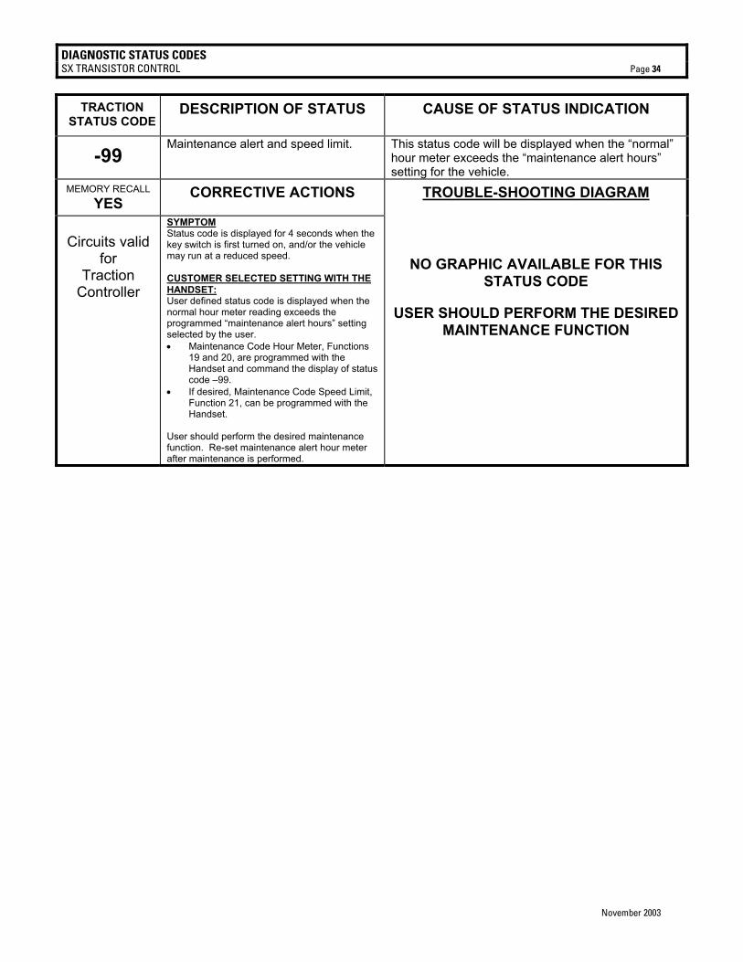
DIAGNOSTIC STATUS CODES SX TRANSISTOR CONTROL Page 34
November 2003
TRACTION STATUS CODE
DESCRIPTION OF STATUS CAUSE OF STATUS INDICATION
-99 Maintenance alert and speed limit. This status code will be displayed when the “normal”
hour meter exceeds the “maintenance alert hours” setting for the vehicle.
MEMORY RECALL YES CORRECTIVE ACTIONS TROUBLE-SHOOTING DIAGRAM
Circuits valid
for Traction
Controller
SYMPTOM Status code is displayed for 4 seconds when the key switch is first turned on, and/or the vehicle may run at a reduced speed. CUSTOMER SELECTED SETTING WITH THE HANDSET: User defined status code is displayed when the normal hour meter reading exceeds the programmed “maintenance alert hours” setting selected by the user. • Maintenance Code Hour Meter, Functions
19 and 20, are programmed with the Handset and command the display of status code –99.
• If desired, Maintenance Code Speed Limit, Function 21, can be programmed with the Handset.
User should perform the desired maintenance function. Re-set maintenance alert hour meter after maintenance is performed.
NO GRAPHIC AVAILABLE FOR THIS STATUS CODE
USER SHOULD PERFORM THE DESIRED MAINTENANCE FUNCTION
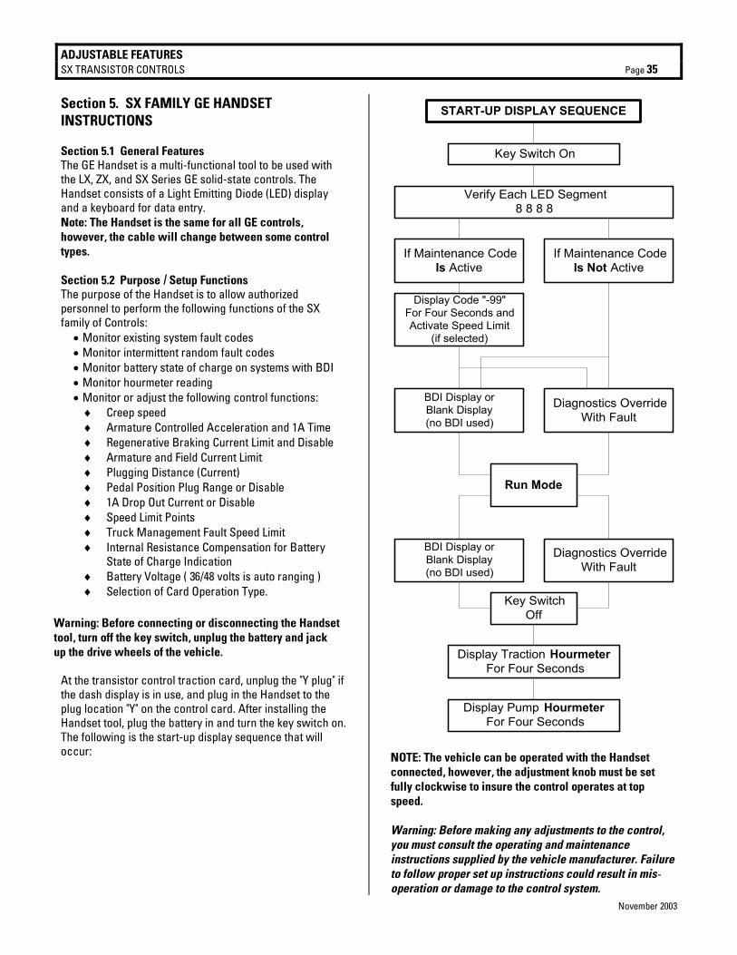
ADJUSTABLE FEATURES SX TRANSISTOR CONTROLS Page 35
November 2003
Section 5. SX FAMILY GE HANDSET INSTRUCTIONS Section 5.1 General Features The GE Handset is a multi-functional tool to be used with the LX, ZX, and SX Series GE solid-state controls. The Handset consists of a Light Emitting Diode (LED) display and a keyboard for data entry. Note: The Handset is the same for all GE controls, however, the cable will change between some control types. Section 5.2 Purpose / Setup Functions The purpose of the Handset is to allow authorized personnel to perform the following functions of the SX family of Controls:
• Monitor existing system fault codes • Monitor intermittent random fault codes • Monitor battery state of charge on systems with BDI • Monitor hourmeter reading • Monitor or adjust the following control functions:
♦ Creep speed ♦ Armature Controlled Acceleration and 1A Time ♦ Regenerative Braking Current Limit and Disable ♦ Armature and Field Current Limit ♦ Plugging Distance (Current) ♦ Pedal Position Plug Range or Disable ♦ 1A Drop Out Current or Disable ♦ Speed Limit Points ♦ Truck Management Fault Speed Limit ♦ Internal Resistance Compensation for Battery
State of Charge Indication ♦ Battery Voltage ( 36/48 volts is auto ranging ) ♦ Selection of Card Operation Type.
At the transistor control traction card, unplug the "Y plug" if the dash display is in use, and plug in the Handset to the plug location "Y" on the control card. After installing the Handset tool, plug the battery in and turn the key switch on. The following is the start-up display sequence that will occur:
START-UP DISPLAY SEQUENCE
Key Switch On
Verify Each LED Segment8 8 8 8
If Maintenance CodeIs Active
If Maintenance CodeIs Not Active
Display Code "-99"For Four Seconds andActivate Speed Limit
(if selected)
BDI Display orBlank Display(no BDI used)
Diagnostics OverrideWith Fault
Run Mode
BDI Display orBlank Display(no BDI used)
Diagnostics OverrideWith Fault
Key SwitchOff
Display Traction HourmeterFor Four Seconds
Display Pump HourmeterFor Four Seconds
NOTE: The vehicle can be operated with the Handset connected, however, the adjustment knob must be set fully clockwise to insure the control operates at top speed. Warning: Before making any adjustments to the control, you must consult the operating and maintenance instructions supplied by the vehicle manufacturer. Failure to follow proper set up instructions could result in mis-operation or damage to the control system.
Warning: Before connecting or disconnecting the Handset tool, turn off the key switch, unplug the battery and jack up the drive wheels of the vehicle.
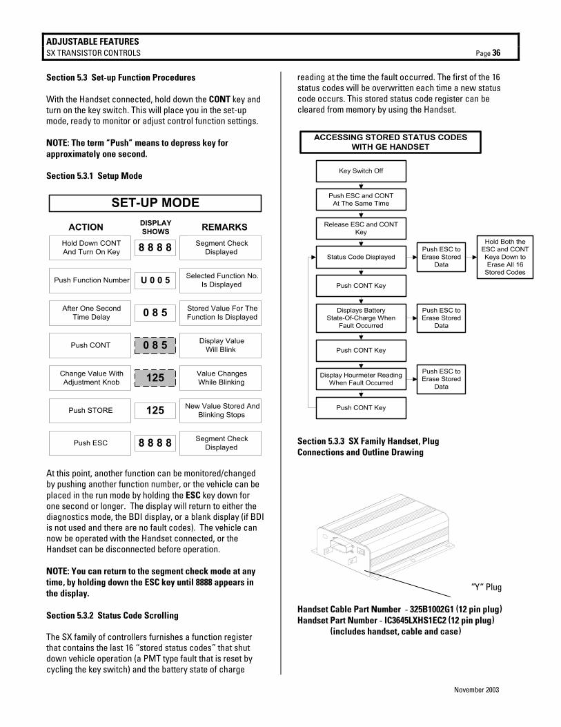
ADJUSTABLE FEATURES SX TRANSISTOR CONTROLS Page 36
November 2003
Section 5.3 Set-up Function Procedures With the Handset connected, hold down the CONT key and turn on the key switch. This will place you in the set-up mode, ready to monitor or adjust control function settings. NOTE: The term “Push” means to depress key for approximately one second. Section 5.3.1 Setup Mode
SET-UP MODE
Hold Down CONTAnd Turn On Key 8 8 8 8 Segment Check
Displayed
ACTION DISPLAYSHOWS REMARKS
Push Function Number U 0 0 5 Selected Function No.Is Displayed
After One SecondTime Delay 0 8 5 Stored Value For The
Function Is Displayed
Push CONT 0 8 5 Display ValueWill Blink
Change Value WithAdjustment Knob
Value ChangesWhile Blinking
Push STORE 125 New Value Stored AndBlinking Stops
Push ESC 8 8 8 8 Segment CheckDisplayed
125
At this point, another function can be monitored/changed by pushing another function number, or the vehicle can be placed in the run mode by holding the ESC key down for one second or longer. The display will return to either the diagnostics mode, the BDI display, or a blank display (if BDI is not used and there are no fault codes). The vehicle can now be operated with the Handset connected, or the Handset can be disconnected before operation. NOTE: You can return to the segment check mode at any time, by holding down the ESC key until 8888 appears in the display. Section 5.3.2 Status Code Scrolling The SX family of controllers furnishes a function register that contains the last 16 “stored status codes” that shut down vehicle operation (a PMT type fault that is reset by cycling the key switch) and the battery state of charge
reading at the time the fault occurred. The first of the 16 status codes will be overwritten each time a new status code occurs. This stored status code register can be cleared from memory by using the Handset.
Key Switch Off
Push ESC and CONTAt The Same Time
Release ESC and CONTKey
Status Code Displayed
Push CONT Key
Displays BatteryState-Of-Charge When
Fault Occurred
Push CONT Key
Display Hourmeter ReadingWhen Fault Occurred
Push CONT Key
ACCESSING STORED STATUS CODESWITH GE HANDSET
Push ESC toErase Stored
Data
Hold Both theESC and CONTKeys Down toErase All 16
Stored Codes
Push ESC toErase Stored
Data
Push ESC toErase Stored
Data
Section 5.3.3 SX Family Handset, Plug Connections and Outline Drawing
“Y“ Plug Handset Cable Part Number - 325B1002G1 (12 pin plug) Handset Part Number - IC3645LXHS1EC2 (12 pin plug) (includes handset, cable and case)
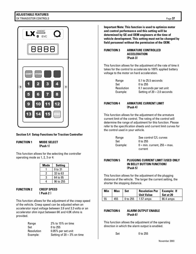
ADJUSTABLE FEATURES SX TRANSISTOR CONTROLS Page 37
November 2003
ESC
LX HANDSET
g EVC
CONT STORE
1
5
+ +
9
13
2
6
10
14
3
7
11
15
4
8
12
Section 5.4 Setup Functions for Traction Controller FUNCTION 1 MODE SELECT (Push 1) This function allows for the selecting the controller operating mode as 1, 2, 3 or 4:
Mode Setting 1 0 to 31 2 32 to 63 3 64 to 95 4 96 to 255
FUNCTION 2 CREEP SPEED ( Push 2 ) This function allows for the adjustment of the creep speed of the vehicle. Creep speed can be adjusted when an accelerator input voltage between 3.9 and 3.3 volts or an accelerator ohm input between 6K and 4.0K ohms is provided. Range 2% to 15% on time Set 0 to 255 Resolution 0.05% per set unit Example: Setting of 20 = 3% on time
Important Note: This function is used to optimize motor and control performance and this setting will be determined by GE and OEM engineers at the time of vehicle development. This setting must not be changed by field personnel without the permission of the OEM. FUNCTION 3 ARMATURE CONTROLLED
ACCELERATION (Push 3) This function allows for the adjustment of the rate of time it takes for the control to accelerate to 100% applied battery voltage to the motor on hard acceleration. Range 0.1 to 25.5 seconds Set 0 to 255 Resolution 0.1 seconds per set unit Example: Setting of 20 = 2.0 seconds FUNCTION 4 ARMATURE CURRENT LIMIT (Push 4) This function allows for the adjustment of the armature current limit of the control. The rating of the control will determine the range of adjustment for this function. Please refer to the specification sheets and current limit curves for the control used in your vehicle. Range See control C/L curves Set 0 to 255 Example: 0 = min. current, 255 = max. current FUNCTION 5 PLUGGING CURRENT LIMIT (USED ONLY
IN BELLY BUTTON FUNCTION) (Push 5) This function allows for the adjustment of the plugging distance of the vehicle. The larger the current setting, the shorter the stopping distance. Min Max Set Resolution Per
Unit Value Example: If Set at 20
55 455 0 to 255 1.57 amps 86.4 amps FUNCTION 6 ALARM OUTPUT ENABLE (Push 6) This function allows the adjustment of the operating direction in which the alarm output is enabled. Set 0 to 255
ADJUSTABLE FEATURES SX TRANSISTOR CONTROLS Page 38
November 2003
Setting Applicable Direction 0 – 128 Reverse only 129 – 255 Forward and reverse FUNCTION 7 MINIMUM FIELD CURRENT (Push 7) This function is set by mode settings 48, 52, 56, and 60. FUNCTION 8 MAX FIELD CURRENT ( Push 8 ) This function allows for the adjustment of the maximum field current in order to obtain the maximum torque of the motor. Min Max Set Resolution Per
Unit Value Example: If Set at 71
0 40 51 to 255 0.185 amps 3.7 amps Important Note: This function is used to optimize motor and control performance, and this setting will be determined by GE and OEM engineers at the time of vehicle development. This setting must not be changed by field personnel without the permission of the OEM. FUNCTION 9 REGEN BRAKING CURRENT LIMIT This function is set by mode settings 51, 55, 59, and 63. FUNCTION 10 FIELD CURRENT FOR REGEN AND PLUG
BRAKING ( Push 10 ) This function allows for the adjustment of the field current to be used during the regen and plug braking modes. Resolution Example Min Max Set Per unit value If set at 71 0 40 51 to 255 .185 amps 3.7 amps Important Note: This function is used to optimize motor and control performance and this setting will be determined by GE and OEM engineers at the time of vehicle development. This setting must not be changed by field personnel without the permission of the OEM.
FUNCTION 11 MAINTENANCE CODE SPEED LIMIT ( Push 11 ) This function allows for the adjustment of the speed limit (maximum battery volts to the motor) when the maintenance code is activated by the control card. Range 100% to 0% of battery volts Set 51 to 180 Resolution 0.78% per set unit Example Setting of 71 = 84% of battery
Volts
FUNCTION 12 WALK SPEED LIMIT ( Push 12 ) This function allows for the adjustment of the speed limit (maximum battery volts to the motor) when the jack rabbit speed limit switch is open.
Range 100% to 0% of battery volts Set 51 to 180 Resolution 0.78% per set unit Example Setting of 71 = 84% of battery
volts FUNCTION 13 FORKS FORWARD SPEED LIMIT ( Push 13 ) This function allows for the adjustment of the forks forward speed limit (maximum battery volts to the motor) when the jack rabbit speed limit switch is closed and the reverse switch is closed.
Range 100% to 0% of battery volts Set 51 to 180 Resolution 0.78% per set unit Example Setting of 71 = 84% of battery
volts FUNCTION 14 INTERNAL RESISTANCE
COMPENSATION ( Push 14 ) This function is used when the Battery Discharge Indicator is present. Adjustment of this function will improve the accuracy of the BDI. In order to determine this setting the voltage drop of the battery under load must first be calculated by the following method. 1. On a fully charged battery, record the open circuit
voltage (Vo) by measuring the voltage at the control positive and negative power terminals.
ADJUSTABLE FEATURES SX TRANSISTOR CONTROLS Page 39
November 2003
2. Load the traction motor to 100 amps, and record the voltage (VL) at the control positive and negative power terminal.
3. Calculate voltage drop (VDrop) as follows: VDrop = VO - VL
4. Use the table below to determine the appropriate setting using the calculated VDrop as a reference.
INTERNAL RESISTANCE COMPENSATION
TABLE
Setting VDrop Setting VDrop 2 11.44 17 01.34 3 07.60 18 01.27 4 05.72 19 01.20 5 04.57 20 01.14 6 03.81 21 01.09 7 03.27 22 01.04 8 02.86 23 00.99 9 02.54 24 00.95 10 02.28 25 00.91 11 02.08 26 00.88 12 01.90 27 00.85 13 01.76 28 00.82 14 01.63 29 00.79 15 01.52 30 00.76 16 01.43 31 00.74
FUNCTION 15 BATTERY VOLTS (Push l5) This function allows for the adjustment of voltage range for controls equipped with the Battery Discharge Indication function. In order for the BDI to operate properly, the setting as shown in the table must be entered: Battery volts Set units 24 volts Between 0 and 31 36 volts Between 32 and 44
FUNCTION 16 PEDAL POSITION PLUG AND REGEN ( Push CONT 1) This function allows for the adjustment of the pedal position braking. Pedal position will reduce the braking current to the current value set by this function as the
accelerator is returned to the creep speed position. Maximum current is obtained with the accelerator in the top speed position. Resolution Example Min Max Set Per unit value If set at 100 45 207 0 to 255 0.8125 per unit 81.25 amps FUNCTION 17 CARD TYPE SELECTION ( Push CONT 2 ) This function allows for the selection of the card type used for your vehicle's application. The table below shows the setting to select card application type, depending on which control card is used.
Setting Autobrake Jog Switch
Pot Type Rollback
0 to 16 No No 5K to 0 Ω No 17 to 32 Yes No 5K to 0 Ω No 33 to 48 No Yes 5K to 0 Ω No 49 to 64 Yes Yes 5K to 0 Ω No 65 to 80 No No 5K to 0 Ω Yes 81 to 96 Yes No 5K to 0 Ω Yes 97 to 112 No Yes 5K to 0 Ω Yes 113 to 127 Yes Yes 5K to 0 Ω Yes Settings for these functions should be made within the ranges indicated above. Warning: These settings must be changed by authorized personnel only, following instructions supplied by the vehicle manufacturer. Card type selection must be made within the capabilities of the control panel used and the supporting electro mechanical devices. Failure to comply with proper application standards could result in mis-operation or damage to the control and/or motors. FUNCTION 18 COAST CONTROL ENABLE ( Push CONT 3) This function is allows the user to enable and disable the coast control input to the control. Set 0 – 255 Setting Status 0 – 128 Coast control enabled 129 – 255 Coast control disabled
The following functions have function numbers larger than the numbers on the Handset keyboard. To
access these functions. Push the CONT key and the number shown in the following instructions at the same time. THE BRAKE SWITCH MUST BE OPEN.
ADJUSTABLE FEATURES SX TRANSISTOR CONTROLS Page 40
November 2003
FUNCTION 19 MAINTENANCE CODE TENS AND UNITS HOURS SET
( Push CONT 4 ) This function allows for the adjustment of the tens and units hours of the maintenance code activation time. Range 0 to 99 Set 0 to 99 Example 9999 Hours FUNCTION 20 MAINTENANCE CODE THOUSANDS
AND HUNDREDS HOURS SET ( Push CONT 5 ) This function allows for the adjustment of the thousands and hundreds hours of the maintenance code activation time. Range 0 to 99 Set 0 to 99 Example 9999 Hours FUNCTION 21 PUMP ENABLE (Push CONT 6) This function enables or disables the BDI lift interrupt feature, which can be selected to occur at 9% battery state of charge. Setting Description 0 to 127 Enables BDI lift interrupt feature 128 to 255 Disables the BDI lift interrupt feature FUNCTION 22 NOT APPLICABLE This function is not applicable to this controller type and should not be adjusted. FUNCTION 23 MOTOR CURRENT DECAY RATE ( Push CONT 8) This function allows for the adjustment of the rate of decay of motor current after a neutral signal is received. Range 0.1 to 1.6 seconds Set 0 to 16 Resolution 0.1 seconds per set unit Example: Setting of 10 = 1.0 second
FUNCTION 24 FIELD WEAKENING START ( Push CONT 9) This function is set by mode settings 49, 53, 57, and 61 . FUNCTION 25 MONITOR ( Push CONT 10) This function allows the monitoring of certain control functions by looking directly at the RAM of the microprocessor. Because absolute memory locations need to be known, this function should not be used without detailed instructions from the GE application engineer. This function should only be adjusted by the vehicle OEM. To ensure optimum operation of the control, this function must be left with zero stored in this register. FUNCTION 26 RATIO ( Push CONT 11) This function is set by mode settings 50, 54, 58, and 62. FUNCTION 27 NOT APPLICABLE This function is not applicable to this controller type and should not be adjusted. FUNCTION 28 STORED STATUS CODE COUNT POINTER ( Push CONT 13) This register contains the location of the last stored status code recorded of the 16 stored status codes. These stored status codes have caused a PMT controller shutdown and/or disruption of normal vehicle operation. To determine which stored status code was the last one recorded, read the number stored in Function 28. Using the Memory Map for your logic card, match the "stored status code pointer number" [the number shown in (bold italics) in the HS (Handset) number column] on the memory map, with the number obtained from Function 28. This will be the last stored status code recorded. Note: When scrolling through the stored status code register, the register always starts at status code 1 and scrolls to status code 16. Instructions for scrolling the register are in section 5.3.2 of this instruction booklet.
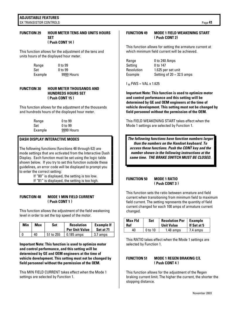
ADJUSTABLE FEATURES SX TRANSISTOR CONTROLS Page 41
November 2003
FUNCTION 29 HOUR METER TENS AND UNITS HOURS SET
( Push CONT 14 ) This function allows for the adjustment of the tens and units hours of the displayed hour meter. Range 0 to 99 Set 0 to 99 Example 9999 Hours FUNCTION 30 HOUR METER THOUSANDS AND
HUNDREDS HOURS SET ( Push CONT 15 ) This function allows for the adjustment of the thousands and hundreds hours of the displayed hour meter. Range 0 to 99 Set 0 to 99 Example 9999 Hours
FUNCTION 48 MODE 1 MIN FIELD CURRENT ( Push CONT 1 ) This function allows the adjustment of the field weakening level in order to set the top speed of the motor.
Min Max Set Resolution Per Unit Value
Example If Set at 71
0 40 51 to 255 0.185 amps 3.7 amps Important Note: This function is used to optimize motor and control performance, and this setting will be determined by GE and OEM engineers at the time of vehicle development. This setting must not be changed by field personnel without the permission of the OEM. This MIN FIELD CURRENT takes effect when the Mode 1 settings are selected by Function 1.
FUNCTION 49 MODE 1 FIELD WEAKENING START ( Push CONT 2) This function allows for setting the armature current at which minimum field current will be achieved. Range 0 to 240 Amps Setting 0 to 147 Resolution 1.625 per set unit Example Setting of 20 = 32.5 amps I M FWS = VAL x 1.625 Important Note: This function is used to optimize motor and control performance and this setting will be determined by GE and OEM engineers at the time of vehicle development. This setting must not be changed by field personnel without the permission of the OEM. This FIELD WEAKENING START takes effect when the Mode 1 settings are selected by Function 1.
FUNCTION 50 MODE 1 RATIO ( Push CONT 3 ) This function sets the ratio between armature and field current when transitioning from minimum field to maximum field current. The setting represents the quantity of field current changed for each 100 amps of armature current changed. Max Fld Ref
Set Resolution Per Unit Value
Example If Set at 5
40 0 to 10 1.48 amps 7.4 amps This RATIO takes effect when the Mode 1 settings are selected by Function 1. FUNCTION 51 MODE 1 REGEN BRAKING C/L ( Push CONT 4 ) This function allows for the adjustment of the Regen braking current limit. The higher the current, the shorter the stopping distance.
DASH DISPLAY INTERACTIVE MODES The following functions (functions 48 through 62) are mode settings that are activated from the Interactive Dash Display. Each function must be set using the logic table shown below. If you try to set this function outside these guidelines, an error code will be displayed to prompt you to enter the correct setting: If “80” is displayed, the setting is too low. If “81” is displayed, the setting is too high.
The following functions have function numbers larger than the numbers on the Handset keyboard. To
access these functions. Push the CONT key and the number shown in the following instructions at the
same time. THE BRAKE SWITCH MUST BE CLOSED.
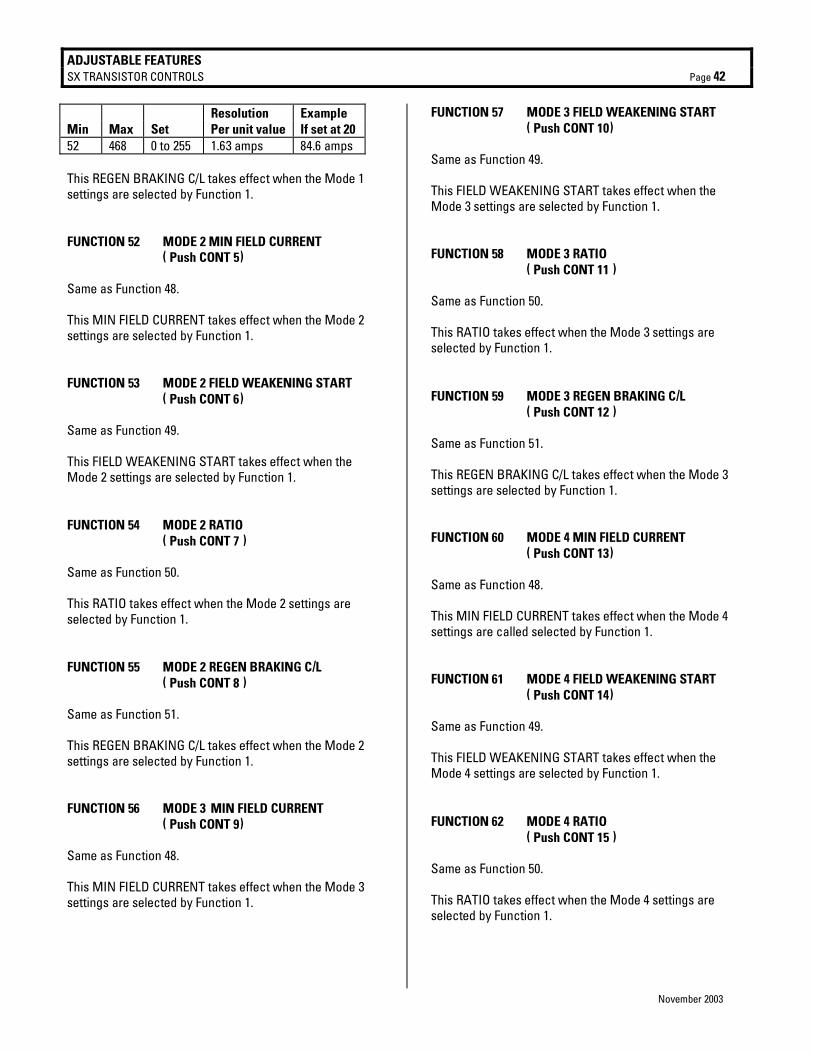
ADJUSTABLE FEATURES SX TRANSISTOR CONTROLS Page 42
November 2003
Resolution Example Min Max Set Per unit value If set at 20 52 468 0 to 255 1.63 amps 84.6 amps This REGEN BRAKING C/L takes effect when the Mode 1 settings are selected by Function 1. FUNCTION 52 MODE 2 MIN FIELD CURRENT ( Push CONT 5) Same as Function 48. This MIN FIELD CURRENT takes effect when the Mode 2 settings are selected by Function 1. FUNCTION 53 MODE 2 FIELD WEAKENING START ( Push CONT 6) Same as Function 49. This FIELD WEAKENING START takes effect when the Mode 2 settings are selected by Function 1. FUNCTION 54 MODE 2 RATIO ( Push CONT 7 ) Same as Function 50. This RATIO takes effect when the Mode 2 settings are selected by Function 1. FUNCTION 55 MODE 2 REGEN BRAKING C/L ( Push CONT 8 ) Same as Function 51. This REGEN BRAKING C/L takes effect when the Mode 2 settings are selected by Function 1. FUNCTION 56 MODE 3 MIN FIELD CURRENT ( Push CONT 9) Same as Function 48. This MIN FIELD CURRENT takes effect when the Mode 3 settings are selected by Function 1.
FUNCTION 57 MODE 3 FIELD WEAKENING START ( Push CONT 10) Same as Function 49. This FIELD WEAKENING START takes effect when the Mode 3 settings are selected by Function 1. FUNCTION 58 MODE 3 RATIO ( Push CONT 11 ) Same as Function 50. This RATIO takes effect when the Mode 3 settings are selected by Function 1. FUNCTION 59 MODE 3 REGEN BRAKING C/L ( Push CONT 12 ) Same as Function 51. This REGEN BRAKING C/L takes effect when the Mode 3 settings are selected by Function 1. FUNCTION 60 MODE 4 MIN FIELD CURRENT ( Push CONT 13) Same as Function 48. This MIN FIELD CURRENT takes effect when the Mode 4 settings are called selected by Function 1. FUNCTION 61 MODE 4 FIELD WEAKENING START ( Push CONT 14) Same as Function 49. This FIELD WEAKENING START takes effect when the Mode 4 settings are selected by Function 1. FUNCTION 62 MODE 4 RATIO ( Push CONT 15 ) Same as Function 50. This RATIO takes effect when the Mode 4 settings are selected by Function 1.
ADJUSTABLE FEATURES SX TRANSISTOR CONTROLS Page 43
November 2003
FUNCTION 63 MODE 4 REGEN BRAKING C/L ( Push CONT ESC ) Same as Function 51. This REGEN BRAKING C/L takes effect when the Mode 4 settings are selected by Function 1.

ADJUSTABLE FEATURES SX TRANSISTOR CONTROLS Page 44
November 2003
Section 5.5 Summary of Current Limit Adjustments
ZERO
MAXIMUM
ZER
O
MAX
IMU
M
FIEL
D C
UR
REN
T
ARMATURE CURRENT
The "minimum fieldcurrent" setting is adjustedby Functions 48, 52, 56 and60. The function sets the topspeed of the motor.
The "maximum field current"setting is adjusted by Function 8.
This function, along with the"maximum armature current"(Function 4), sets the maximum
torque of the motor.
The "maximum armaturecurrent" setting is adjusted by
Function 4. The function, along withthe "maximum field current",(Function 8) sets the maximum
torque of the motor.
The " field weakening start "setting is adjusted by Functions 49,
53, 57 and 61. This function sets thearmature current at which minimum
field current will achieved .
The " ratio" setting is adjusted by Functions50, 54, 58 and 62. This function sets the ratio
between armature and field current whentransitioning from minimum field to maximum
field current. Setting is the value of field currentchanged for each 100 amps of armature current
changed.
The "full load transition point"is calculated by the control. Thisfunction sets the maximum field
current transition point atapproximately 80% of maximum
armature current.
The "error compensation" setting is adjusted byFunction 23. This function is used to reduce theripple in field current due to the interactionbetween motor field design and the digital fieldcurrent regulation circuit. The value for thisfunction will be defined by the GE applicationengineer.
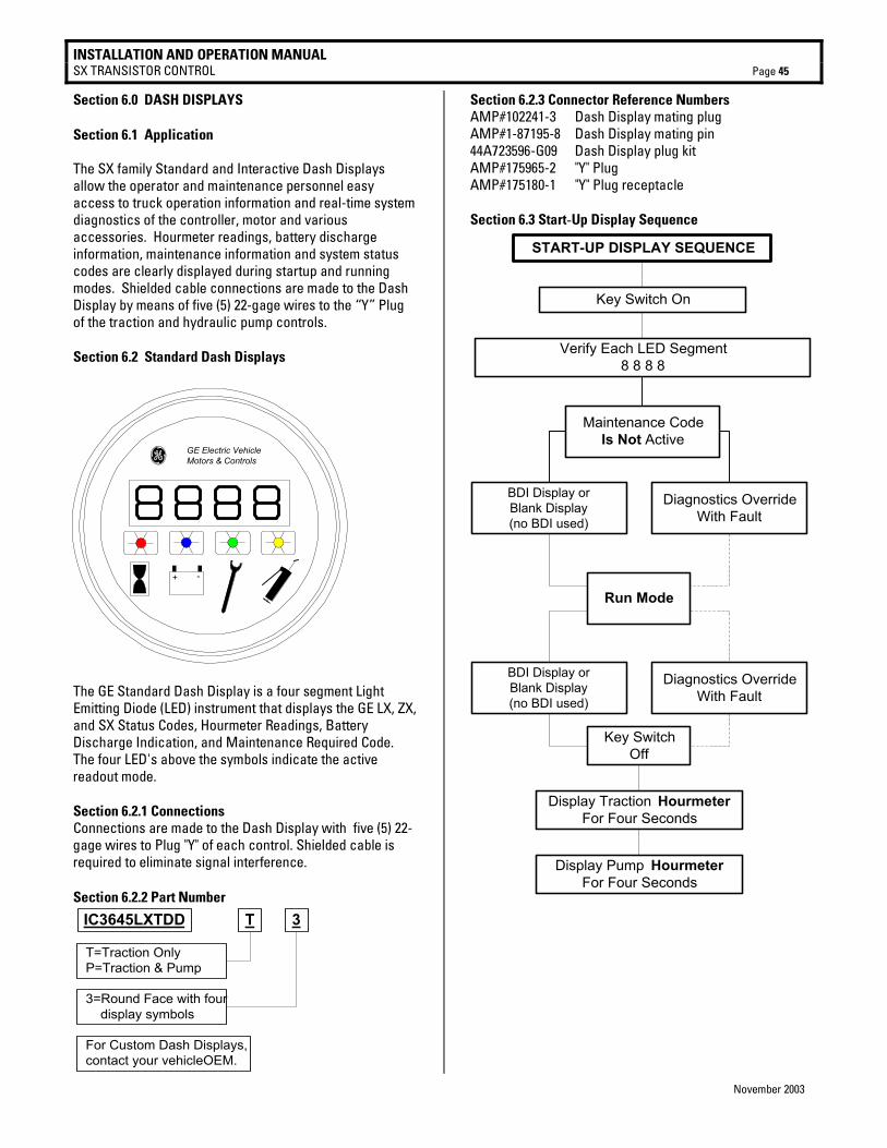
INSTALLATION AND OPERATION MANUAL SX TRANSISTOR CONTROL Page 45
November 2003
Section 6.0 DASH DISPLAYS Section 6.1 Application The SX family Standard and Interactive Dash Displays allow the operator and maintenance personnel easy access to truck operation information and real-time system diagnostics of the controller, motor and various accessories. Hourmeter readings, battery discharge information, maintenance information and system status codes are clearly displayed during startup and running modes. Shielded cable connections are made to the Dash Display by means of five (5) 22-gage wires to the “Y” Plug of the traction and hydraulic pump controls. Section 6.2 Standard Dash Displays
The GE Standard Dash Display is a four segment Light Emitting Diode (LED) instrument that displays the GE LX, ZX, and SX Status Codes, Hourmeter Readings, Battery Discharge Indication, and Maintenance Required Code. The four LED's above the symbols indicate the active readout mode. Section 6.2.1 Connections Connections are made to the Dash Display with five (5) 22-gage wires to Plug "Y" of each control. Shielded cable is required to eliminate signal interference. Section 6.2.2 Part Number
IC3645LXTDD T 3
T=Traction OnlyP=Traction & Pump
3=Round Face with four display symbols
For Custom Dash Displays,contact your vehicleOEM.
Section 6.2.3 Connector Reference Numbers AMP#102241-3 Dash Display mating plug AMP#1-87195-8 Dash Display mating pin 44A723596-G09 Dash Display plug kit AMP#175965-2 "Y" Plug AMP#175180-1 "Y" Plug receptacle Section 6.3 Start-Up Display Sequence
START-UP DISPLAY SEQUENCE
Key Switch On
Verify Each LED Segment8 8 8 8
Maintenance CodeIs Not Active
BDI Display orBlank Display(no BDI used)
Diagnostics OverrideWith Fault
Run Mode
BDI Display orBlank Display(no BDI used)
Diagnostics OverrideWith Fault
Key SwitchOff
Display Traction HourmeterFor Four Seconds
Display Pump HourmeterFor Four Seconds
g GE Electric VehicleMotors & Controls
+ -
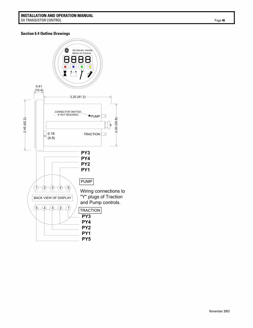
INSTALLATION AND OPERATION MANUAL SX TRANSISTOR CONTROL Page 46
November 2003
Section 6.4 Outline Drawings
g GE Electric VehicleMotors & Controls
+ -
PY3PY4PY2PY1PY5
1 2 3 4 5
5 4 3 2 1
PY3PY4PY2PY1
PUMP
TRACTION
BACK VIEW OF DISPLAY
Wiring connections to"Y" plugs of Tractionand Pump controls.
2.45
(62.
2)
3.20 (81.3)
0.19(4.8)
2.00
(50.
8)PUMP
TRACTION
CONNECTOR OMITTEDIF NOT REQUIRED
0.41(10.4)
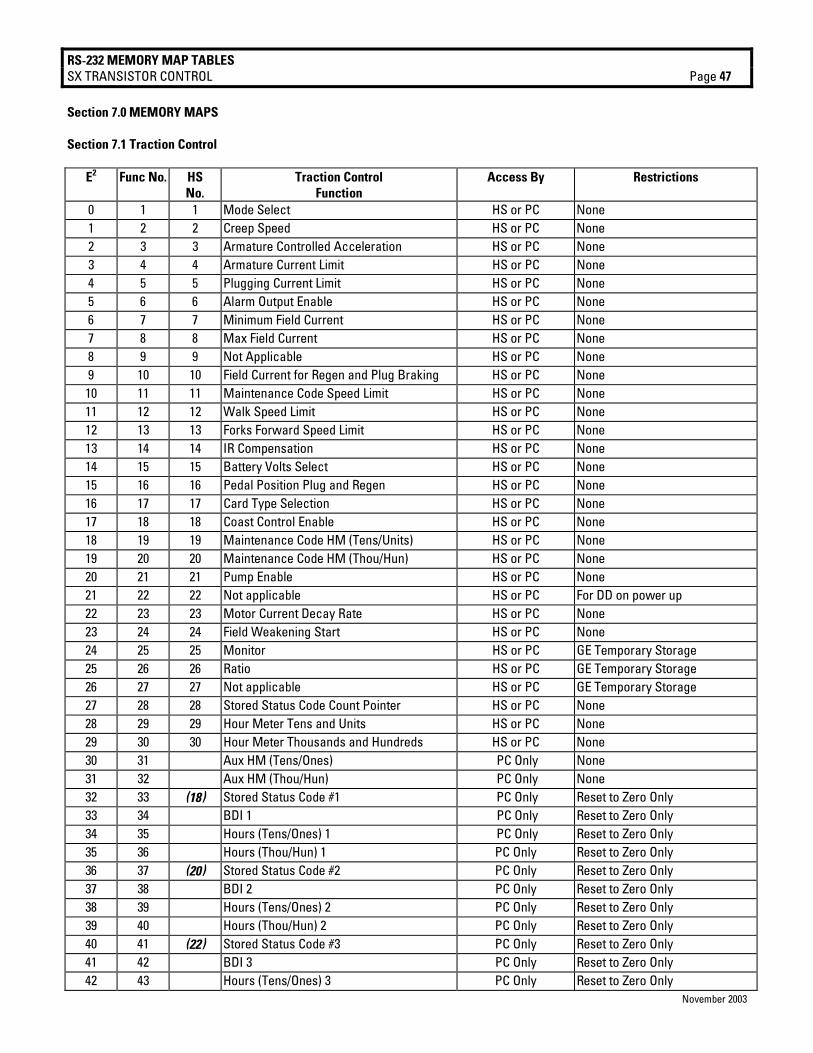
RS-232 MEMORY MAP TABLES SX TRANSISTOR CONTROL Page 47
November 2003
Section 7.0 MEMORY MAPS Section 7.1 Traction Control
E2 Func No. HS No.
Traction Control Function
Access By Restrictions
0 1 1 Mode Select HS or PC None 1 2 2 Creep Speed HS or PC None 2 3 3 Armature Controlled Acceleration HS or PC None 3 4 4 Armature Current Limit HS or PC None 4 5 5 Plugging Current Limit HS or PC None 5 6 6 Alarm Output Enable HS or PC None 6 7 7 Minimum Field Current HS or PC None 7 8 8 Max Field Current HS or PC None 8 9 9 Not Applicable HS or PC None 9 10 10 Field Current for Regen and Plug Braking HS or PC None 10 11 11 Maintenance Code Speed Limit HS or PC None 11 12 12 Walk Speed Limit HS or PC None 12 13 13 Forks Forward Speed Limit HS or PC None 13 14 14 IR Compensation HS or PC None 14 15 15 Battery Volts Select HS or PC None 15 16 16 Pedal Position Plug and Regen HS or PC None 16 17 17 Card Type Selection HS or PC None 17 18 18 Coast Control Enable HS or PC None 18 19 19 Maintenance Code HM (Tens/Units) HS or PC None 19 20 20 Maintenance Code HM (Thou/Hun) HS or PC None 20 21 21 Pump Enable HS or PC None 21 22 22 Not applicable HS or PC For DD on power up 22 23 23 Motor Current Decay Rate HS or PC None 23 24 24 Field Weakening Start HS or PC None 24 25 25 Monitor HS or PC GE Temporary Storage 25 26 26 Ratio HS or PC GE Temporary Storage 26 27 27 Not applicable HS or PC GE Temporary Storage 27 28 28 Stored Status Code Count Pointer HS or PC None 28 29 29 Hour Meter Tens and Units HS or PC None 29 30 30 Hour Meter Thousands and Hundreds HS or PC None 30 31 Aux HM (Tens/Ones) PC Only None 31 32 Aux HM (Thou/Hun) PC Only None 32 33 (18) Stored Status Code #1 PC Only Reset to Zero Only 33 34 BDI 1 PC Only Reset to Zero Only 34 35 Hours (Tens/Ones) 1 PC Only Reset to Zero Only 35 36 Hours (Thou/Hun) 1 PC Only Reset to Zero Only 36 37 (20) Stored Status Code #2 PC Only Reset to Zero Only 37 38 BDI 2 PC Only Reset to Zero Only 38 39 Hours (Tens/Ones) 2 PC Only Reset to Zero Only 39 40 Hours (Thou/Hun) 2 PC Only Reset to Zero Only 40 41 (22) Stored Status Code #3 PC Only Reset to Zero Only 41 42 BDI 3 PC Only Reset to Zero Only 42 43 Hours (Tens/Ones) 3 PC Only Reset to Zero Only
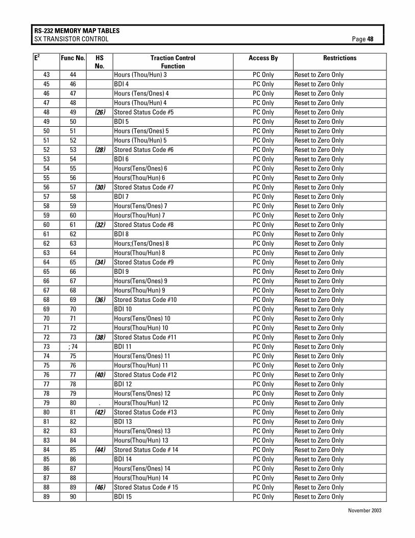
RS-232 MEMORY MAP TABLES SX TRANSISTOR CONTROL Page 48
November 2003
E2 Func No. HS No.
Traction Control Function
Access By Restrictions
43 44 Hours (Thou/Hun) 3 PC Only Reset to Zero Only 45 46 BDI 4 PC Only Reset to Zero Only 46 47 Hours (Tens/Ones) 4 PC Only Reset to Zero Only 47 48 Hours (Thou/Hun) 4 PC Only Reset to Zero Only 48 49 (26) Stored Status Code #5 PC Only Reset to Zero Only 49 50 BDI 5 PC Only Reset to Zero Only 50 51 Hours (Tens/Ones) 5 PC Only Reset to Zero Only 51 52 Hours (Thou/Hun) 5 PC Only Reset to Zero Only 52 53 (28) Stored Status Code #6 PC Only Reset to Zero Only 53 54 BDI 6 PC Only Reset to Zero Only 54 55 Hours(Tens/Ones) 6 PC Only Reset to Zero Only 55 56 Hours(Thou/Hun) 6 PC Only Reset to Zero Only 56 57 (30) Stored Status Code #7 PC Only Reset to Zero Only 57 58 BDI 7 PC Only Reset to Zero Only 58 59 Hours(Tens/Ones) 7 PC Only Reset to Zero Only 59 60 Hours(Thou/Hun) 7 PC Only Reset to Zero Only 60 61 (32) Stored Status Code #8 PC Only Reset to Zero Only 61 62 BDI 8 PC Only Reset to Zero Only 62 63 Hours;(Tens/Ones) 8 PC Only Reset to Zero Only 63 64 Hours(Thou/Hun) 8 PC Only Reset to Zero Only 64 65 (34) Stored Status Code #9 PC Only Reset to Zero Only 65 66 BDI 9 PC Only Reset to Zero Only 66 67 Hours(Tens/Ones) 9 PC Only Reset to Zero Only 67 68 Hours(Thou/Hun) 9 PC Only Reset to Zero Only 68 69 (36) Stored Status Code #10 PC Only Reset to Zero Only 69 70 BDI 10 PC Only Reset to Zero Only 70 71 Hours(Tens/Ones) 10 PC Only Reset to Zero Only 71 72 Hours(Thou/Hun) 10 PC Only Reset to Zero Only 72 73 (38) Stored Status Code #11 PC Only Reset to Zero Only 73 ; 74 BDI 11 PC Only Reset to Zero Only 74 75 Hours(Tens/Ones) 11 PC Only Reset to Zero Only 75 76 Hours(Thou/Hun) 11 PC Only Reset to Zero Only 76 77 (40) Stored Status Code #12 PC Only Reset to Zero Only 77 78 BDI 12 PC Only Reset to Zero Only 78 79 Hours(Tens/Ones) 12 PC Only Reset to Zero Only 79 80 . Hours(Thou/Hun) 12 PC Only Reset to Zero Only 80 81 (42) Stored Status Code #13 PC Only Reset to Zero Only 81 82 BDI 13 PC Only Reset to Zero Only 82 83 Hours(Tens/Ones) 13 PC Only Reset to Zero Only 83 84 Hours(Thou/Hun) 13 PC Only Reset to Zero Only 84 85 (44) Stored Status Code # 14 PC Only Reset to Zero Only 85 86 BDI 14 PC Only Reset to Zero Only 86 87 Hours(Tens/Ones) 14 PC Only Reset to Zero Only 87 88 Hours(Thou/Hun) 14 PC Only Reset to Zero Only 88 89 (46) Stored Status Code # 15 PC Only Reset to Zero Only 89 90 BDI 15 PC Only Reset to Zero Only

RS-232 MEMORY MAP TABLES SX TRANSISTOR CONTROL Page 49
November 2003
90 91 Hours (Tens/Ones) 15 PC Only Reset to Zero Only E2 Func No. HS
No. Traction Control
Function Access By Restrictions
90 91 Hours (Tens/Ones) 15 PC Only Reset to Zero Only 91 92 Hours (Thou/Hun) 15 PC Only Reset to Zero Only 92 93 (48) Stored Status Code #16 PC Only Reset to Zero Only 94 95 Hours (Tens/Ones) 16 PC Only Reset to Zero Only 95 96 Hours (Thou/Hun) 16 PC Only Reset to Zero Only 96 97 48 Mode 1 Min Field Current HS or PC None 97 98 49 Mode 1 Field Weakening Start HS or PC None 98 99 50 Mode 1 Ratio HS or PC None 99 100 51 Mode 1 Regen Braking Current Limit HS or PC None 100 101 52 Mode 2 Min Field Current HS or PC None 101 102 53 Mode 2 Field Weakening Start HS or PC None 102 103 54 Mode 2 Ratio HS or PC None 103 104 55 Mode 2 Regen Braking Current Limit HS or PC None 104 105 56 Mode 3 Min Field Current HS or PC None 105 106 57 Mode 3 Field Weakening Start HS or PC None 106 107 58 Mode 3 Ratio HS or PC None 107 108 59 Mode 3 Regen Braking Current Limit HS or PC None 108 109 60 Mode 4 Min Field Current HS or PC None 109 110 61 Mode 4 Field Weakening Start HS or PC None 110 111 62 Mode 4 Ratio HS or PC None 111 112 63 Mode 4 Regen Braking Current Limit HS or PC None 112 113 Secure HM (Tens/Ones) PC Only OEM Read Only 113 114 Secure HM (Thou/Hun) PC Only OEM Read Only 114 115 Secure Aux HM (Tens/Ones) PC Only OEM Read Only 115 116 Secure Aux HM (Thou/Hun) PC Only OEM Read Only 116 117 Reserved PC Only GE Future Use 117 118 Reserved PC Only GE Future Use 118 119 Reserved PC Only GE Future Use 119 120 Reserved PC Only GE Future Use 120 121 OEM Use PC Only None 121 122 OEM Use PC Only None 122 123 OEM Use PC Only None 123 124 OEM Use PC Only None 124 125 OEM Use PC Only None 125 126 OEM Use PC Only None 126 127 OEM Use PC Only None 127 128 OEM Use PC Only None
Numbers in (bold italics) are Stored Status Code pointers.