separation kit rmk-4 - icom · foreword thank you for purchas ng the rmk-4 separation kit. the...
TRANSCRIPT
INSTRUCTION MANUAL
RMK-4SEPARATION KIT
�
FOREWORD
Thank you for purchas�ng the RMK-4 separation kit.The RMK-4 allows you to connect the add�t�onal CONTROL HEAD to the IC-F9511HT to enable dual-head operat�on. Depend�ng on the length of separat�on you need, use e�ther the opt�onal OPC-607, OPC-608, OPC-609 or OPC-726 sep-aration cable w�th the RMK-4.
EXPLICIT DEFINITIONS
WORD DEFINITION
RWARNINGPersonal �njury, fire hazard or electr�c shock may occur.
CAUTION Equ�pment damage may occur.
NOTEIf d�sregarded, �nconven�ence only. No r�sk of personal �njury, fire or electr�c shock.
Please refer to the �nstruct�on manual of the transce�ver for deta�ls of the bas�c operat�on.
PRECAUTIONSRWARNING! NEVER place the transce�ver’s ma�n un�t (w�th the RMK-4) and CONTROL HEADs where normal operat�on of the veh�cle may be h�ndered or where they could cause bod�ly �njury.
CAUTION! To avo�d damage to the transce�ver, turn the power OFF and d�sconnect the DC power cable from the trans-ce�ver’s ma�n un�t before d�sassemble the transce�ver.
DO NOT use or place the transce�ver’s ma�n un�t (w�th the RMK-4) and CONTROL HEADs �n areas w�th temperatures below –30°C (–22°F) or above +60°C (+140°F).
DO NOT use chem�cal agents such as benz�ne or alcohol when clean�ng, as they can damage the RMK-4 and CONTROL HEAD’s surfaces.
USE the spec�f�ed m�crophone only. Other m�crophones have d�fferent p�n ass�gnments and may damage CONTROL HEAD or the transce�ver’s ma�n un�t.
KEEP the transce�ver’s ma�n un�t (w�th the RMK-4) and CON-TROL HEADs away from heavy ra�n, and never �mmerse them �n the water.The transce�ver’s ma�n un�t (w�th the RMK-4) and CONTROL HEADs meet IP54 requ�rements for dust-protect�on and splash res�stance when the opt�onal m�crophone*, the front/rear plate(s) and the speaker jack cover of CONTROL HEAD are attached.However, �f these �tems are dropped, dust-protect�on and splash res�stance cannot be guaranteed because of poss�ble damage to the cases or the waterproof seals.* The m�crophone �s not dust-protect�on and splash res�stant.
Icom, Icom Inc. and the Icom logo are reg�stered trademarks of Icom Incor-porated (Japan) �n Japan, the Un�ted States, the Un�ted K�ngdom, Germany, France, Spa�n, Russ�a and/or other countr�es.All other products or brands are reg�stered trademarks or trademarks of the�r respect�ve holders.

��
12345678910111213141516
KEY-STICKER
Second CONTROL HEAD
RMK-4 (Main unit attachment)
Microphone hanger and screw set
Mounting bracketfor CONTROL HEAD
Flat washers (M5)
Springwashers (M5)
Mounting screws (M5×12)
Self-tapping screws (M5×16)
Bracket screwsNuts (M5)
Key caps
Function namestickers• Used for labelling
the programmable function keys. See at right for details.
The serial number seal is put here, and labeled “RMK-4.”
• Function name stickersThere are no labels on the programmable funct�on keys s�nce the funct�ons can be freely ass�gned to these keys.Attach the suppl�ed funct�on name st�ckers to the appropr�ate keys for easy recogn�t�on of the key’s ass�gned funct�on as shown below.Then, protect the attached st�ckers from com�ng off w�th the suppl�ed key cap, as shown below.
Function name stickerKey cap
ACCESSORIES
TABLE OF CONTENTS
���
FOREWORD ......................................................................... �EXPLICIT DEFINITIONS ....................................................... �PRECAUTIONS ..................................................................... �ACCESSORIES .................................................................... ��TABLE OF CONTENTS ....................................................... ���
1 CONNECTION .............................................................1–5 ■ Remov�ng the transce�ver’s ma�n un�t attachment ........1 ■ Connect�ng CONTROL HEAD and RMK-4 ..................2 ■ Attach�ng the RMK-4 ....................................................4 ■ Mount�ng ......................................................................5
2 REMOTE BOX SET MODE .........................................6–8 ■ Set mode �tems ............................................................6
3 DUAL-HEAD OPERATION ........................................9–10 ■ Intercom funct�on ..........................................................9 ■ TX AF Mon�tor�ng funct�on ..........................................10 ■ NOTES .......................................................................10
4 OPTIONS .......................................................................11

q Turn the power OFF, then d�sconnect the DC power cable from the transce�ver’s ma�n un�t.
w Unscrew the 6 top screws, then remove the top cover from the transce�ver’s ma�n un�t �n the d�rect�on of the arrow.
Top cover
Main unit
e Unscrew the screw that �s attached to the chass�s.
Front
r Unscrew the 4 front screws, then remove the ma�n un�t attachment from the ma�n un�t �n the d�rect�on of the arrow.
• The flat cable should be carefully d�sconnected from the attachment.
Main unit attachment
Main unit attachment
Flat cable
t Unscrew the 4 screws, then remove the front plate from the ma�n un�t attachment. Then unscrew the c�rcu�t board screw, and d�sconnect the separat�on cable, �f �t �s connected.
Main unitattachment
Separation cable
Front plateRemove the circuit board screw.
IMPORTANT: Set the top, chass�s and front screws as�de as they are needed for the RMK-4 �nstallat�on.
1
1CONNECTION
12345678910111213141516
■ Removing the transceiver’s main unit attachment
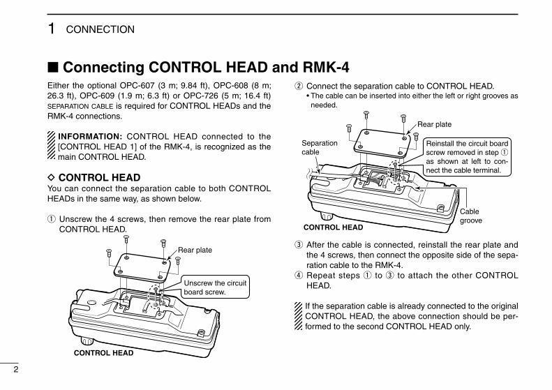
E�ther the opt�onal OPC-607 (3 m; 9.84 ft), OPC-608 (8 m; 26.3 ft), OPC-609 (1.9 m; 6.3 ft) or OPC-726 (5 m; 16.4 ft) separation cable �s requ�red for CONTROL HEADs and the RMK-4 connect�ons.
INFORMATION: CONTROL HEAD connected to the [CONTROL HEAD 1] of the RMK-4, �s recogn�zed as the ma�n CONTROL HEAD.
D CONTROL HEADYou can connect the separat�on cable to both CONTROL HEADs �n the same way, as shown below.
q Unscrew the 4 screws, then remove the rear plate from CONTROL HEAD.
CONTROL HEAD
Rear plate
Unscrew the circuit board screw.
w Connect the separat�on cable to CONTROL HEAD. • The cable can be �nserted �nto e�ther the left or r�ght grooves as
needed.
Separationcable
Cablegroove
CONTROL HEAD
Reinstall the circuit board screw removed in step q as shown at left to con-nect the cable terminal.
Rear plate
e After the cable �s connected, re�nstall the rear plate and the 4 screws, then connect the oppos�te s�de of the sepa-rat�on cable to the RMK-4.
r Repeat steps q to e to attach the other CONTROL HEAD.
If the separat�on cable �s already connected to the or�g�nal CONTROL HEAD, the above connect�on should be per-formed to the second CONTROL HEAD only.
2
1 CONNECTION
■ Connecting CONTROL HEAD and RMK-4

3
1CONNECTION
12345678910111213141516
D RMK-4q Unscrew the 4 screws, then remove the front plate from
the RMK-4.
RMK-4
Front plate
Unscrew the circuit board screw.
w Connect the oppos�te s�de of the separat�on cable that �s connected to CONTROL HEAD to the RMK-4. After the cable �s connected, re�nstall the front plate and the 4 screws.
• The cable can be �nserted �nto e�ther the left or r�ght grooves as needed.
Separationcable
Cable grooves
Reinstall the circuit board screw removed in step q as shown above to con-nect the cable terminal.
e Repeat steps q and w for the other s�de connect�on.
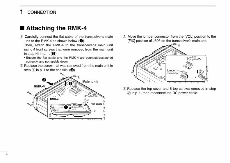
■ Attaching the RMK-4q Carefully connect the flat cable of the transce�ver’s ma�n
un�t to the RMK-4 as shown below (q). Then, attach the RMK-4 to the transce�ver’s ma�n un�t
us�ng 4 front screws that were removed from the ma�n un�t �n step r �n p. 1. (w)
• Ensure the flat cable and the RMK-4 are connected/attached correctly, and not ups�de down.
w Replace the screw that was removed from the ma�n un�t �n step e �n p. 1 to the chass�s. (e)
Main unitRMK-4
RMK-4
we
Flat cable
q
e Move the jumper connector from the [VOL] pos�t�on to the [FIX] pos�t�on of J806 on the transce�ver’s ma�n un�t.
VOLFIX
Jumperconnector
r Replace the top cover and 6 top screws removed �n step w �n p. 1, then reconnect the DC power cable.
4
1 CONNECTION

■ Mounting2 types of mount�ng styles are ava�lable— one �s on-board mount�ng, and the other one �s overhead mount�ng.
D On-board mountingMount the controller securely w�th the 4 suppl�ed screws to a sol�d surface.
Bracketscrew
D Overhead mountingMount the controller securely w�th the 4 suppl�ed screws to a sol�d surface wh�ch can support more than 2 kg (4.40 lb). (Overhead mount�ng)
When usingself-tapping screws
Flat washer
Spring washer
Bracketscrew
Nut
5
1CONNECTION
12345678910111213141516

The REMOTE BOX SET MODE �s accessed at power ON and allows you to set seldom-changed sett�ngs. You can “custom�ze” CONTROL HEADs for dual-head operat�on to su�t your preferences and operat�ng style.
P0 P4P3P2P1
*In this instruction manual, these keys are from the left, designated [P0]/[P1]/[P2]/[P3]/[P4].
D Set mode operationq F�rst, be sure power �s OFF. Then, wh�le push�ng and
hold�ng [P0], [P1] and [P2], push [ ] to turn the power ON.
• Hold [P0], [P1] and [P2] unt�l “SET MODE FOR REMOTE BOX” appears on the d�splay.
w Push [P0] to enter the REMOTE BOX SET MODE.e Then push [P0] add�t�onal t�mes to select the appropr�ate
�tem. Then, push [Up] or [Down] to set the des�red level and cond�t�ons.
r Push and hold [ ] to ex�t the REMOTE BOX SET MODE.
The USER SET MODE �s also ava�lable. The common funct�ons that can be used w�th both dual-head and s�n-gle-head operat�ons are set �n the USER SET MODE. Please refer to the �nstruct�on manual of the transce�ver for deta�ls.
■ Set mode itemsThe follow�ng funct�ons (other than “RX Speaker Tune”) can be programmed �nto CONTROL HEADs 1 and 2, �nd�v�du-ally.
D AF MinimumSet the AF M�n�mum funct�on to ON or OFF. (default: ON)
ON : The m�n�mum aud�o output level �s set for CONTROL HEADs.
• Set the m�n�mum aud�o output level �n “AF M�n�mum Level” as shown below.
OFF : The m�n�mum aud�o output level �s not set for CON-TROL HEADs.
D AF Minimum LevelSet the m�n�mum aud�o output level between 0 and 255. (default: 0)Th�s sett�ng �s effect�ve only when “AF M�n�mum” �s ON as shown above.
D Beep LevelSet the output level of the conf�rmat�on beeps between 1 and 5. (default: 3)Th�s sett�ng �s effect�ve for dual-head operat�on funct�ons only.The beep level for other funct�ons that can be used w�th both dual-head and s�ngle-head operat�ons, are set �n the USER SET MODE.
6
2 REMOTE BOX SET MODE

D Panel Lock functionSet the Panel Lock funct�on to ON or OFF. (default: ON)The Panel Lock funct�on locks all keys and the d�al other than [ ] and [P4 (PANEL LOCK)].
ON : The [PANEL LOCK] funct�on �s ass�gned to [P4], and you can toggle the Panel Lock funct�on ON and OFF w�th push�ng and hold�ng [P4 (PANEL LOCK)] for 1 sec.
OFF : [P4] reta�ns the or�g�nally programmed funct�on and the Panel Lock funct�on �s OFF.
NOTE: When th�s funct�on �s set to ON, the key funct�on [Null] must be ass�gned to [P4] by the CS-F9010/F9510 cloning software on both CONTROL HEADs for match-�ng the CONTROL HEAD’s performance. Ask your dealer for deta�ls.
D TX AF Monitoring functionSet the TX AF Mon�tor�ng funct�on to ON or OFF. (default: ON)Th�s funct�on allows the operator of CONTROL HEAD to mon�tor the other s�de’s commun�cat�on.When one CONTROL HEAD operator �s commun�cat�ng, the aud�o can be heard from the SP-22 external speaker on the other CONTROL HEAD s�de.The opt�onal SP-22 external speaker �s requ�red.
D Hanger functionSet the Hanger funct�on to ON or OFF. (default: ON)The m�crophone “on-hook” funct�on (Hook-on scan) and “off-hook” funct�ons (Move to Pr�or�ty A CH and Mon�tor) are act�-vated accord�ng to th�s sett�ng.
ON : The m�crophone “on-hook” or “off-hook” funct�ons are act�vated when CONTROL HEAD’s m�crophone �s put on (on hook) or taken off (off-hook) �t's hanger hook.
OFF : The m�crophone “on-hook” funct�on �s act�vated regard-less of the CONTROL HEAD’s m�crophone “on-hook” and “off-hook”.
NOTE: If “ON” �s set �n both CONTROL HEADs and one of the two m�crophones �s taken from �ts hanger hook, the m�crophone “off-hook” funct�ons are act�vated for both CONTROL HEADs.
7
2REMOTE BOX SET MODE
12345678910111213141516

8
2 REMOTE BOX SET MODE
D RX Speaker Tuning functionSet the RX Speaker Tun�ng funct�on to ON or OFF for CON-TROL HEAD 1 (ma�n). (default: OFF)Th�s funct�on allows the operator of CONTROL HEAD 1 to adjust the output level of the external speaker that �s con-nected to the transce�ver’s ma�n un�t.
ON : The aud�o output level of the external speaker �s adjust-able w�th the AF volume control knob on CONTROL HEAD 1.
The m�n�mum aud�o output level must be set to more than 1 on the transce�ver’s ma�n un�t �n order to avo�d mut�ng the aud�o output.
OFF : The aud�o output level of the external speaker �s not adjustable by CONTROL HEADs.
D Intercom functionSet the Intercom funct�on to ON or OFF. (default: ON)The Intercom funct�on allows CONTROL HEAD operators to commun�cate each other v�a the�r m�crophones.The opt�onal m�crophone and the SP-22 external speaker are requ�red.
ON : The [INTERCOM] funct�on �s ass�gned to [P3], and you can enter and ex�t the Intercom mode by push�ng [P3 (INTERCOM)].
OFF : [P3] reta�ns the or�g�nally programmed funct�on and the Intercom funct�on �s OFF.
NOTE:• When one CONTROL HEAD enters the Intercom mode,
the other CONTROL HEAD also enters even �f th�s func-t�on �s set to OFF.
• When th�s funct�on �s set to ON, the key funct�on [Null] must be ass�gned to [P3] by the CS-F9010/F9510 clon-ing software on both CONTROL HEADs for match�ng the CONTROL HEAD’s performance. Ask your dealer for deta�ls.

9
3DUAL-HEAD OPERATION
12345678910111213141516
■ Intercom function[P3] �s used for the Intercom funct�on ON/OFF sw�tch when the Intercom funct�on �s set to ON �n the REMOTE BOX SET MODE. (No other funct�on can be ass�gned.)The Intercom funct�on allows the operators of CONTROL HEAD 1 and 2 to commun�cate each other v�a the�r m�cro-phones.The opt�onal m�crophone and the SP-22 external speaker are requ�red.
NOTE:• Transm�tt�ng �s �mposs�ble dur�ng �ntercom operat�on.• Dur�ng �ntercom operat�on, when [PTT] �s pushed and
held on the caller’s s�de, any rece�ved rad�o s�gnal �s muted on the l�stener s�de’s CONTROL HEAD external speaker. However, the rece�ved rad�o s�gnal can be heard on the caller s�de’s CONTROL HEAD external speaker and the ma�n un�t’s external speaker.
• When the message s�gnal �s rece�ved, �t �s not d�splayed on the LCD of CONTROL HEADs dur�ng �ntercom opera-t�on. After ex�t�ng the �ntercom mode, �t w�ll be d�splayed on the LCD.
• Dur�ng �ntercom operat�on, CONTROL HEADs 1 and 2 return to the normal operat�on mode, �f no [PTT] opera-t�on �s performed for 30 sec.
q Push [P3 (INTERCOM)] to enter the �ntercom mode. • The other CONTROL HEAD �s also set to the Intercom mode
automat�cally even �f th�s funct�on �s set to OFF. • “INTERCOM” appears on both CONTROL HEADs.w Push and hold [PTT] and speak at a normal vo�ce level
�nto the m�crophone. • “IN USE” bl�nks on the l�stener s�de. • To adjust the aud�o output level, rotate [VOL].e After releas�ng [PTT] you can hear the response through
the speaker.r To return to normal operat�on, push [P3 (INTERCOM)].
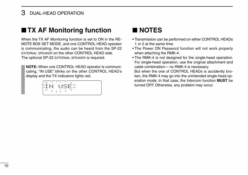
■ TX AF Monitoring functionWhen the TX AF Mon�tor�ng funct�on �s set to ON �n the RE-MOTE BOX SET MODE, and one CONTROL HEAD operator �s commun�cat�ng, the aud�o can be heard from the SP-22 external speaker on the other CONTROL HEAD s�de.The opt�onal SP-22 external speaker �s requ�red.
NOTE: When one CONTROL HEAD operator �s commun�-cat�ng, “IN USE” bl�nks on the other CONTROL HEAD’s d�splay and the TX �nd�cators l�ghts red.
IN USE
■ NOTES• Transm�ss�on can be performed on e�ther CONTROL HEADs
1 or 2 at the same t�me.• The Power ON Password funct�on w�ll not work properly
when attach�ng the RMK-4.• The RMK-4 �s not des�gned for the s�ngle-head operat�on.
For s�ngle-head operat�on, use the or�g�nal attachment and cable comb�nat�on— no RMK-4 �s necessary.
But when the one of CONTROL HEADs �s acc�dently bro-ken, the RMK-4 may go �nto the un�ntended s�ngle-head op-erat�on mode. In that case, the Intercom funct�on MUST be turned OFF. Otherw�se, any problem may occur.
10
3 DUAL-HEAD OPERATION

11
4OPTIONS
12345678910111213141516
• OPC-607/OPC-608/OPC-609/OPC-726 separation cables
Used for CONTROL HEAD and the RMK-4 connect�on. OPC-607 : 3 m; 9.84 ft OPC-608 : 8 m; 26.3 ft OPC-609 : 1.9 m; 6.3 ft OPC-726 : 5 m; 16.4 ft
• HM-152/HM-152T/HM-148G/HM-148T hand microphones
HM-152 : Hand m�crophone HM-152T : DTMF m�crophone HM-148G : Self ground�ng heavy duty m�crophone HM-148T : Self ground�ng heavy duty DTMF m�crophone
• SM-25 desktop microphone
• SP-22 external speaker
Compact and easy-to-�nstall. Input �mpedance : 4 ø Max. �nput power : 5 W * The SP-22 �s not recommended for use w�th the IC-F9511HT.
Use the SP-30 �nstead.
Icom opt�onal equ�pment are des�gned for opt�mal performance when used w�th th�s product. We are not respons�ble for the product be�ng damaged or any acc�dent caused when us�ng non-Icom opt�onal equ�pment.
Some opt�ons may not be ava�lable �n some countr�es. Please ask your dealer for deta�ls.

1-1-32 Kam�m�nam�, H�rano-ku, Osaka 547-0003, Japan
A-6757H-1US-qPr�nted �n Japan© 2009 Icom Inc.