serial crystallography using x-ray free electron lasers · serial crystallography using x-ray free...
TRANSCRIPT

Serial
Crystallography
using x-rayFree Electron Lasers
Milan, July 11th 2014
Francesco Stellato
I.N.F.N. – Sezione di Roma ‘Tor Vergata’
Structural biology and X-rays
From synchrotrons to Free Electron Lasers
Diffract-and-destroy measurements
Serial Crystallography at FELs
Sample Preparation and Charcterization
Sample delivery
Data analysis
The Cathepsin B experiment
Serial Crystallography at synchrotrons
Applications & Future perspectives
Summary

Structural Biology and X-rays
1E+001E+031E+061E+091E+121E+151E+181E+211E+241E+271E+301E+331E+36
1880 1910 1940 1970 2000 2030
Year
So
urc
e P
ea
k B
rilli
an
ce
Röntgen
Bragg & Bragg
reflections
von Laue
crystal diffraction
Hodgkin
penicillin,
B12
Perutz & Kendrew
myoglobin
Franklin,
Crick,
Watson
DNA
MacKinnon
Potassium
channel
Kornberg
RNA
polymerase
Jacobsen
Holography
Kirz &
Schmahl
Microscopy
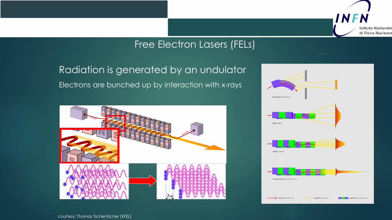
Free Electron Lasers (FELs)
Radiation is generated by an undulator
Electrons are bunched up by interaction with x-rays
courtesy: Thomas Tschentscher (XFEL)

LINAC Coherent Light Source
FLASH
FLASH
Hamburg,
Germany
λ > 4.2 nm
LCLS
Stanford
USA
λ > 0.12 nm
FELs around the world
Soft x-rays
FERMITrieste Italy
SACLA
Rikken
Japan
Under construction
Hard x-rays
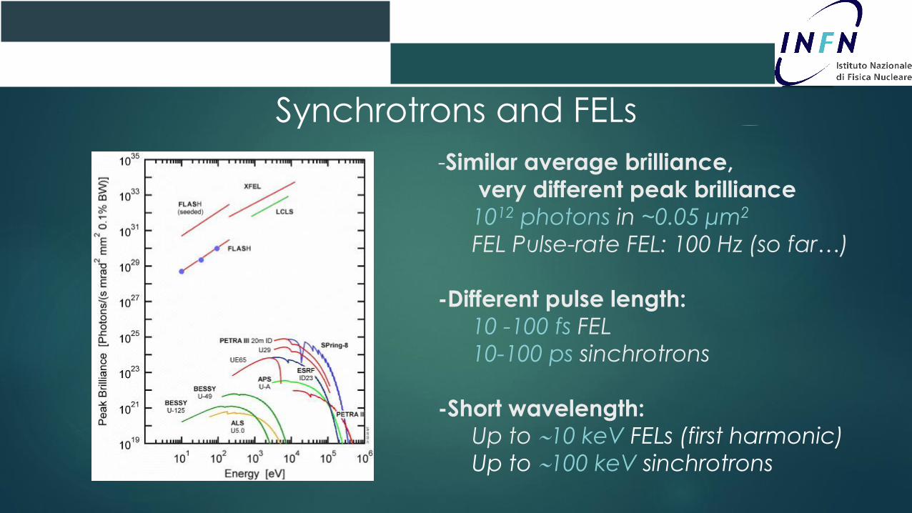
Synchrotrons and FELs
-Similar average brilliance,
very different peak brilliance
1012 photons in ~0.05 μm2
FEL Pulse-rate FEL: 100 Hz (so far…)
-Different pulse length:
10 -100 fs FEL
10-100 ps sinchrotrons
-Short wavelength:
Up to 10 keV FELs (first harmonic)
Up to 100 keV sinchrotrons
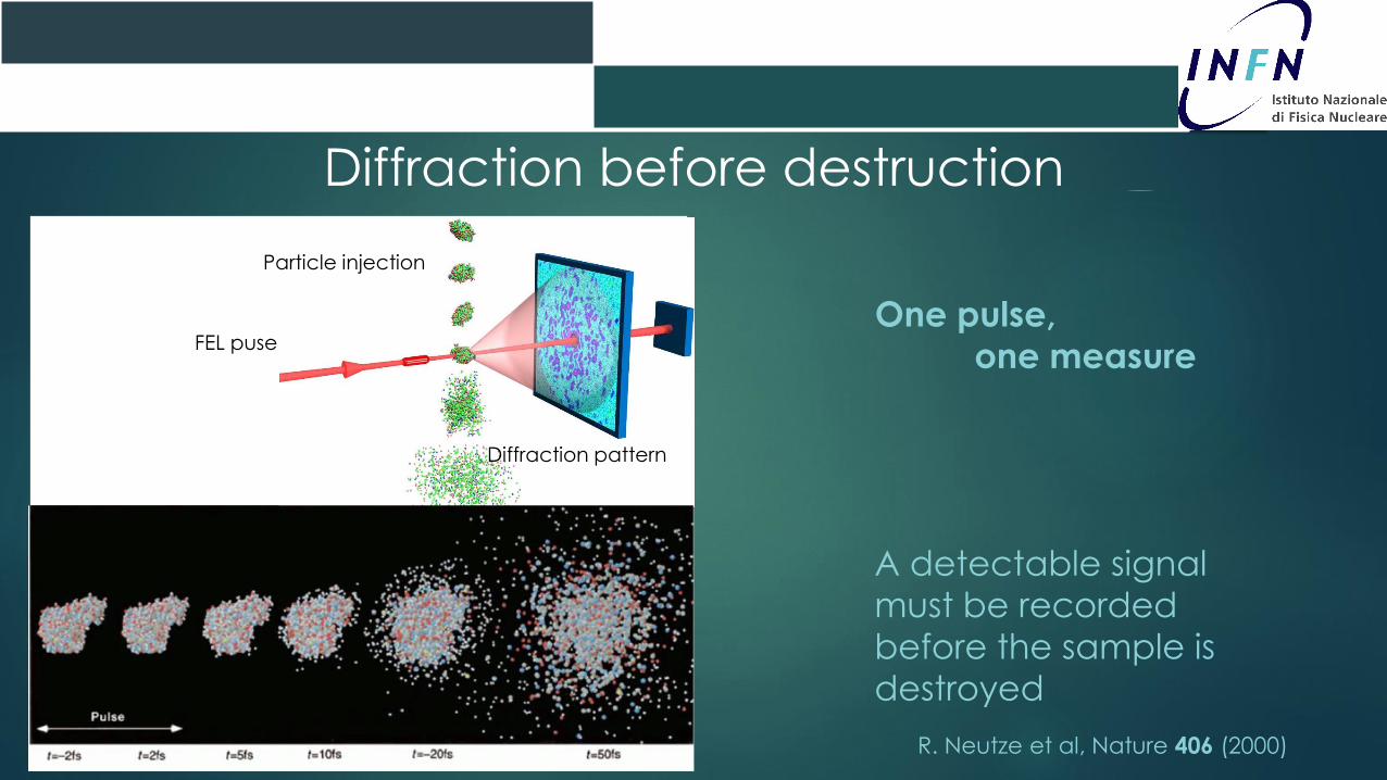
Diffraction before destruction
Diffraction pattern
FEL puse
Particle injection
One pulse,
one measure
R. Neutze et al, Nature 406 (2000)
A detectable signal
must be recorded
before the sample is
destroyed

Coherent x-ray ImagingDiffract and destroy proof-of-principle
First pulse
Second pulse
1 micron
SEM picture of a FIB-bed pattern
etched on a Si3N4membrane
Chapman et al. Nature Physics (2006)
Reconstructed image at
32 nm resolution
1 micron
FLASH
Diffraction patternDiffraction pattern
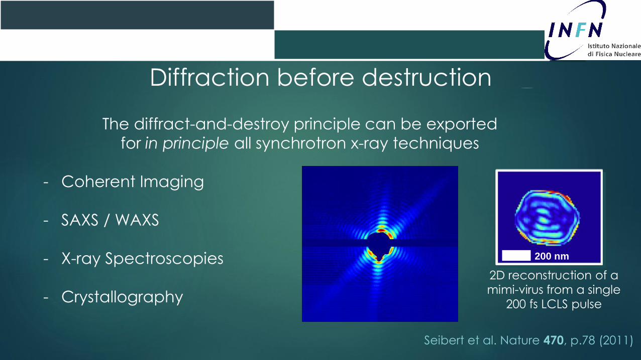
Diffraction before destruction
The diffract-and-destroy principle can be exported
for in principle all synchrotron x-ray techniques
- Coherent Imaging
- SAXS / WAXS
- X-ray Spectroscopies
- Crystallography
200 nm
2D reconstruction of a
mimi-virus from a single
200 fs LCLS pulse
Seibert et al. Nature 470, p.78 (2011)

FEL Serial Crystallography
- Measurements of many (103-104)
single crystal diffraction patterns
- Indexing
- Intensities determination & merging
- Standard (and non-standard)
phasing methods0
10000
20000
30000
40000
50000
60000
70000
1972 1976 1980 1984 1988 1992 1996 2000 2004 2008
Electron
NMR
X-ray
Standard crystallography is the election
technique for structural biology
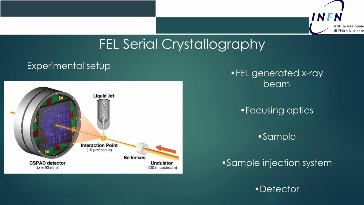
FEL Serial Crystallography
Experimental setup•FEL generated x-ray
beam
•Focusing optics
•Sample
•Sample injection system
•Detector
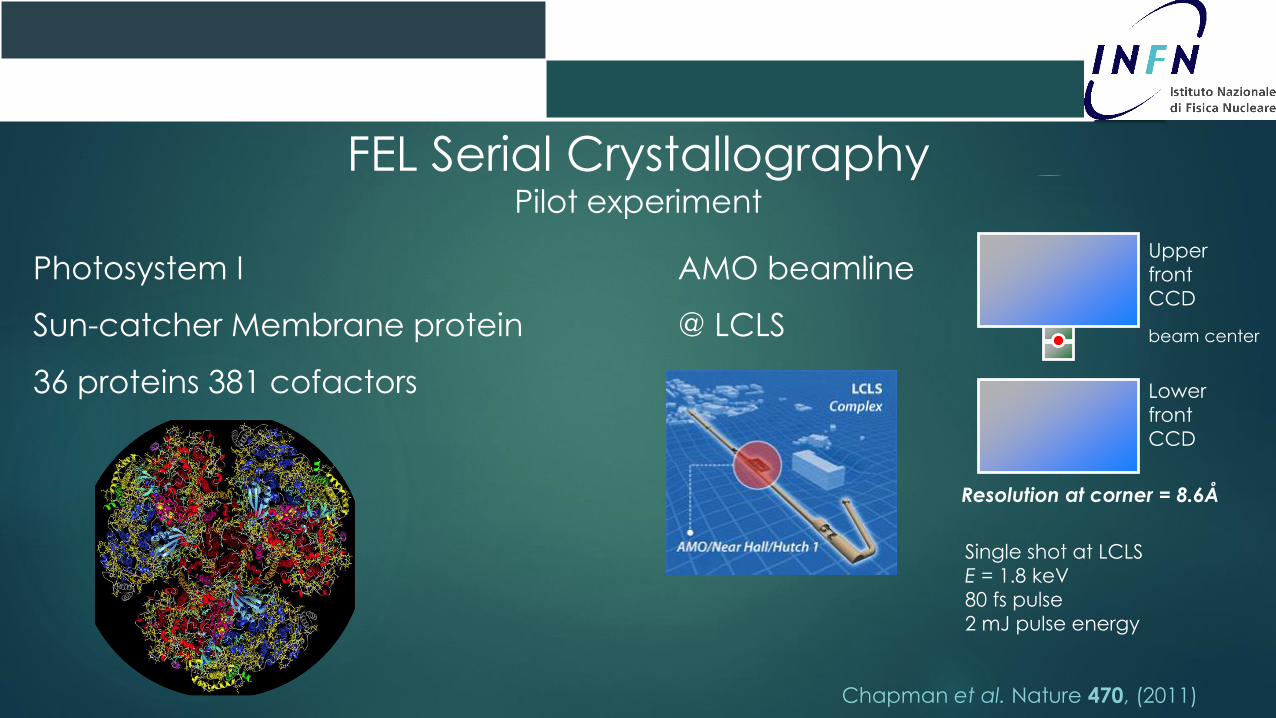
FEL Serial CrystallographyPilot experiment
Chapman et al. Nature 470, (2011)
Photosystem I
Sun-catcher Membrane protein
36 proteins 381 cofactors
AMO beamline
@ LCLS
Single shot at LCLS
E = 1.8 keV
80 fs pulse
2 mJ pulse energy
Upper
front
CCD
Lower
front
CCD
Resolution at corner = 8.6Å
beam center
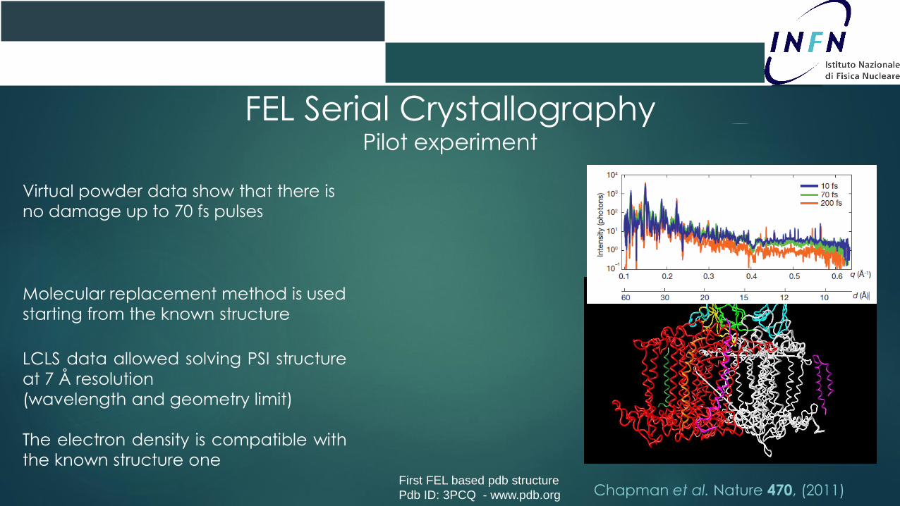
FEL Serial CrystallographyPilot experiment
Chapman et al. Nature 470, (2011)
LCLS data allowed solving PSI structure
at 7 Å resolution
(wavelength and geometry limit)
The electron density is compatible with
the known structure one
Virtual powder data show that there is
no damage up to 70 fs pulses
Molecular replacement method is used
starting from the known structure
First FEL based pdb structure
Pdb ID: 3PCQ - www.pdb.org

Needle-
shaped
Cathepsin B
Nanocrystals
A Proteinase K
Nanocrystal
SEM images
Standard techniques can be
optimized to grow many micro-
and/or nano-crystals:
- Hanging droplet (robots)
-Batch methods
- In vivo crystallization
Nano/micro-crystals Preparation
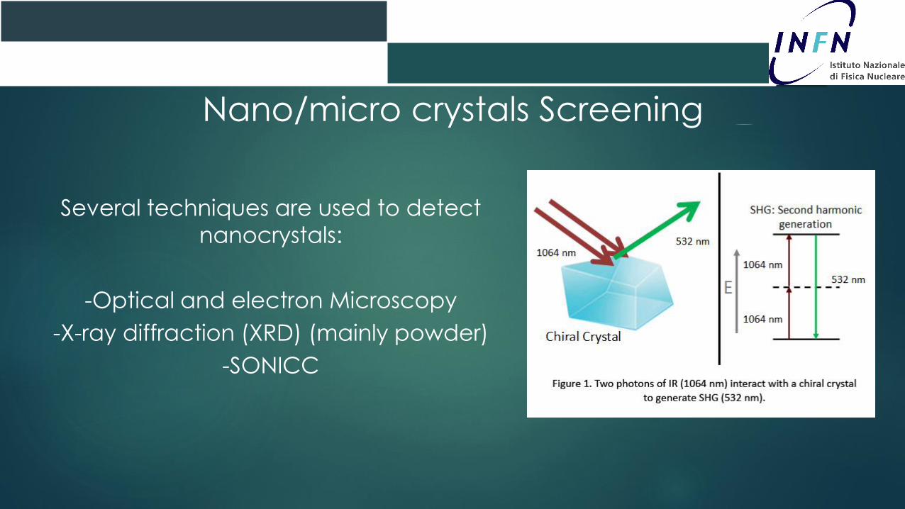
Several techniques are used to detect
nanocrystals:
-Optical and electron Microscopy
-X-ray diffraction (XRD) (mainly powder)
-SONICC
Nano/micro crystals Screening
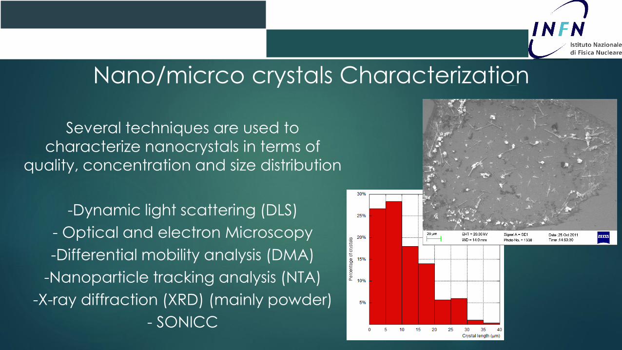
Several techniques are used to
characterize nanocrystals in terms of
quality, concentration and size distribution
-Dynamic light scattering (DLS)
- Optical and electron Microscopy
-Differential mobility analysis (DMA)
-Nanoparticle tracking analysis (NTA)
-X-ray diffraction (XRD) (mainly powder)
- SONICC
Nano/micrco crystals Characterization
Sample Delivery
A good sample delivery system
should:
-Keep the sample as close as possible
to native conditions
-Have low background
-Deliver a fresh crystal at every FEL
pulse
-Use as few crystals as possible
-Allow pump-probe measurements
-Be as stable as possible
Systems used so far at FELs:
-Gas Dynamic Virtual Nozzle
-Lipidic cubic phase nozzle
-Aerosol injector
-Electrospinning
-Fix targets
-…
Sample Delivery Systems
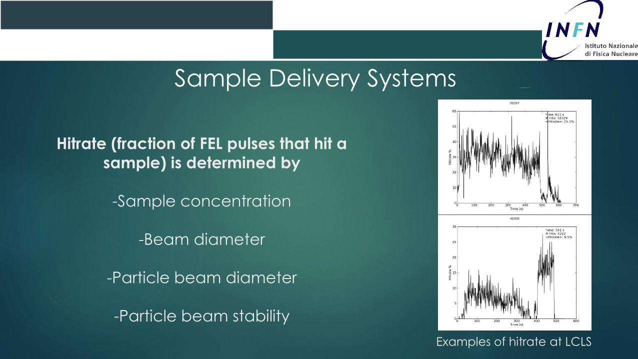
Hitrate (fraction of FEL pulses that hit a
sample) is determined by
-Sample concentration
-Beam diameter
-Particle beam diameter
-Particle beam stability
Examples of hitrate at LCLS
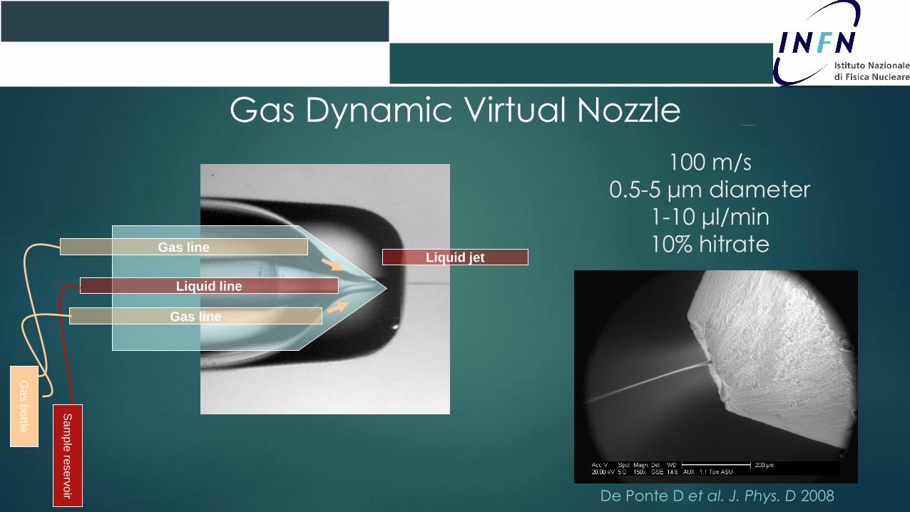
Liquid line
Gas lineLiquid jet
100 m/s
0.5-5 μm diameter
1-10 μl/min
10% hitrate
Gas line
Ga
s b
ottle
Sa
mp
le re
serv
oir
Gas Dynamic Virtual Nozzle
De Ponte D et al. J. Phys. D 2008

A drop-on-demand
system can be used
to generate 20-40 μm
diameter droplets
An electrospray
source can generate
small droplets and an
associated
Differential Mobility
Analyzer can size-
select particlesCone-Jet Mode
Electrospray/Electrospinning & Drop-on-demand
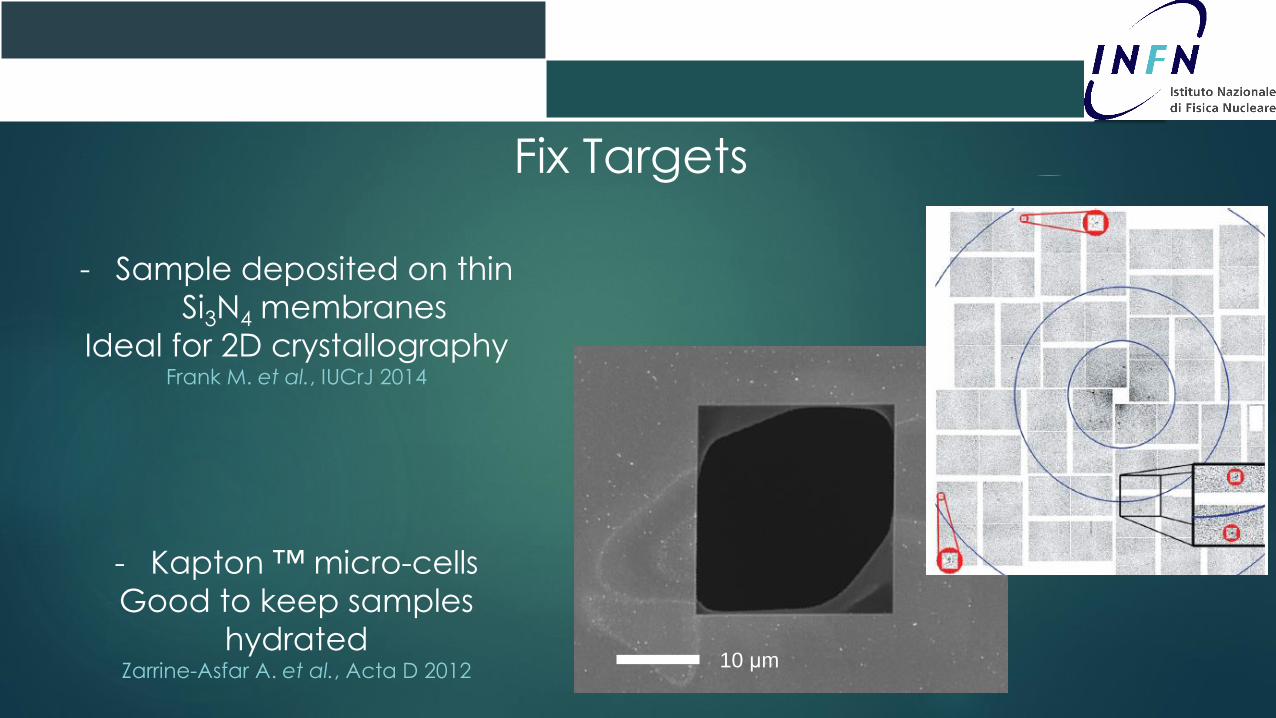
- Sample deposited on thin
Si3N4 membranes
Ideal for 2D crystallographyFrank M. et al., IUCrJ 2014
- Kapton ™ micro-cells
Good to keep samples
hydratedZarrine-Asfar A. et al., Acta D 2012
10 μm
Fix Targets
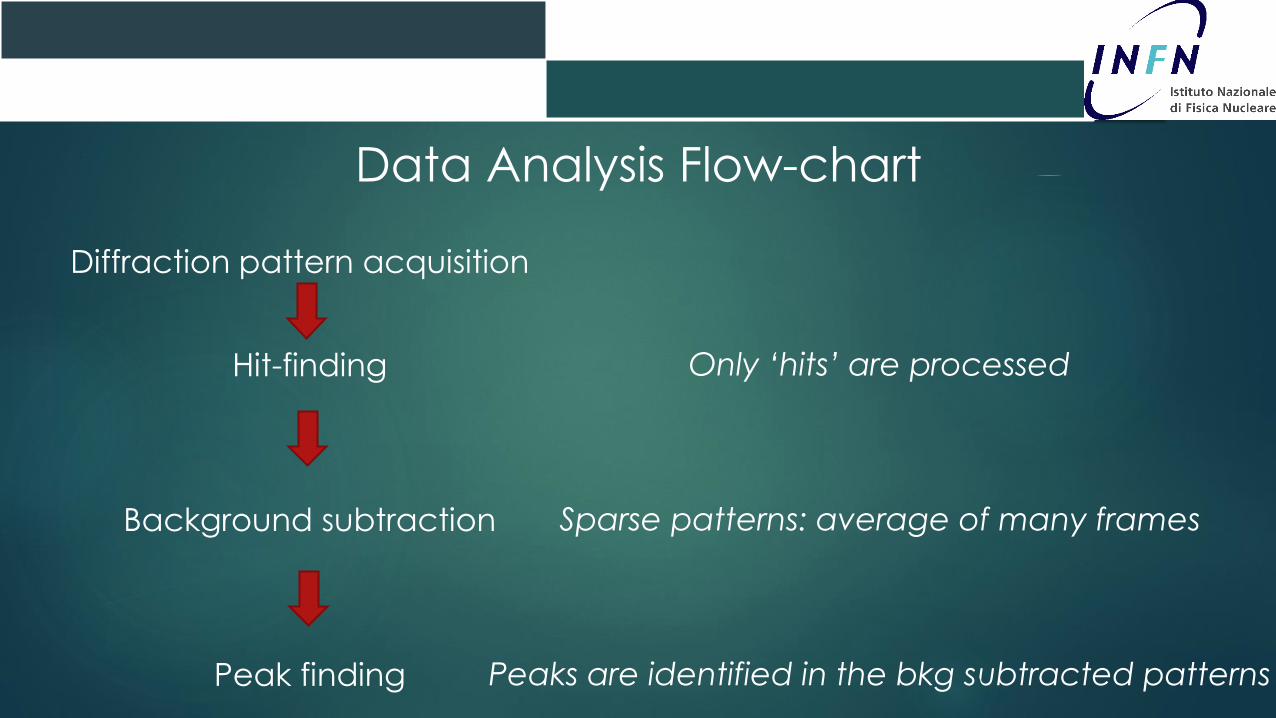
Diffraction pattern acquisition
Hit-finding
Background subtraction
Peak finding
Data Analysis Flow-chart
Only ‘hits’ are processed
Sparse patterns: average of many frames
Peaks are identified in the bkg subtracted patterns
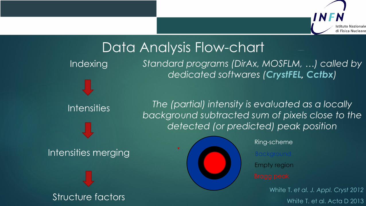
Indexing
Intensities
Intensities merging
Structure factors
Data Analysis Flow-chart
White T. et al. J. Appl. Cryst 2012
White T. et al. Acta D 2013
Standard programs (DirAx, MOSFLM, …) called by
dedicated softwares (CrystFEL, Cctbx)
The (partial) intensity is evaluated as a locally
background subtracted sum of pixels close to the
detected (or predicted) peak position
Ring-scheme
Background
Empty region
Bragg peak
Serial Crystallography – Cathepsin B
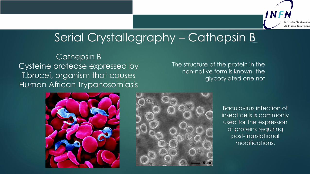
Cathepsin B
Cysteine protease expressed by
T.brucei, organism that causes
Human African Trypanosomiasis
Luci di Sincrotrone
CNR – Roma, 22 Aprile 2014
The structure of the protein in the
non-native form is known, the
glycosylated one not
Baculovirus infection of
insect cells is commonly
used for the expression
of proteins requiring
post-translational
modifications.
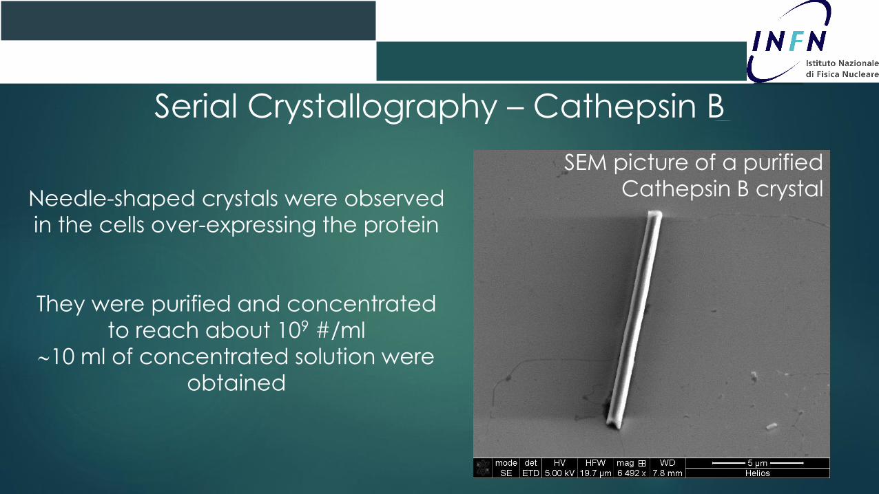
Needle-shaped crystals were observed
in the cells over-expressing the protein
They were purified and concentrated
to reach about 109 #/ml
10 ml of concentrated solution were
obtained
Luci di Sincrotrone
CNR – Roma, 22 Aprile 2014
Serial Crystallography – Cathepsin B
SEM picture of a purified
Cathepsin B crystal

Synchrotron data
60s exposure pattern have been
collected at DORIS, Hamburg
1010 photons/s in 200x200 μm2
There is a clearly visible ring at 60 Å
Faint rings at higher (20-40 Å)
resolution.
1s exposure pattern have been
collected at SLS, Switzerland
1011 photons/s in 20x20 μm2
Bragg spots are visible up to 8 Å
Why such a low resolution?
Essentially, because of damage
Serial Crystallography – Cathepsin B
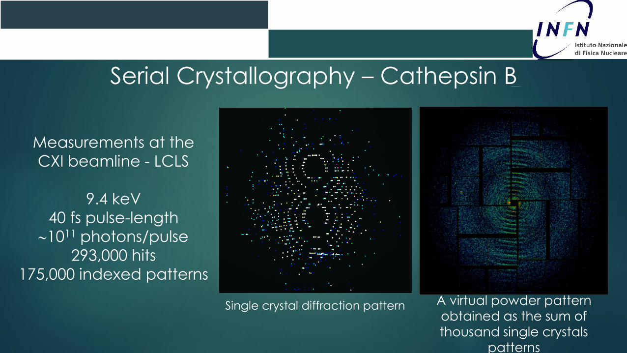
Single crystal diffraction pattern
Serial Crystallography – Cathepsin B
Measurements at the
CXI beamline - LCLS
9.4 keV
40 fs pulse-length
1011 photons/pulse
293,000 hits
175,000 indexed patterns
A virtual powder pattern
obtained as the sum of
thousand single crystals
patterns

Projection of the measured intensities on
two planes in the reciprocal space
Serial Crystallography – Cathepsin B

3D structure of the fully
glycosylated protein
Redecke et al., Science
2013
Serial Crystallography – Cathepsin B
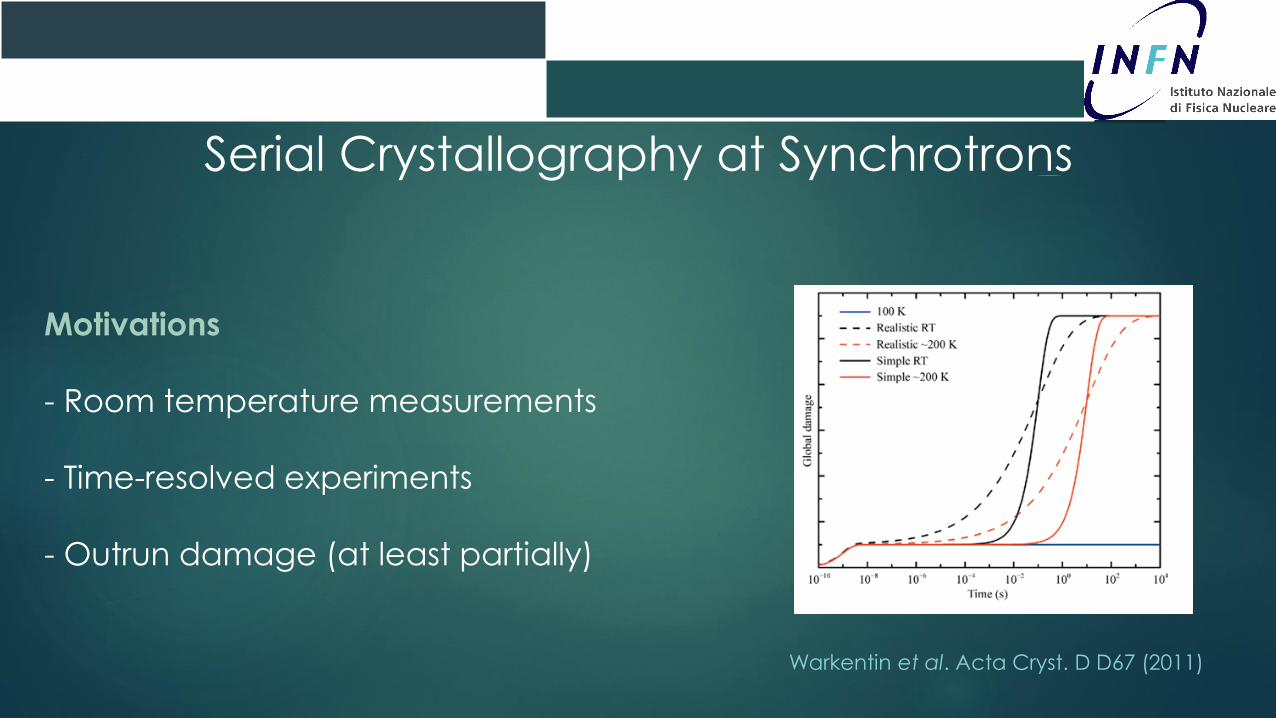
Motivations
- Room temperature measurements
- Time-resolved experiments
- Outrun damage (at least partially)
Serial Crystallography at Synchrotrons
Warkentin et al. Acta Cryst. D D67 (2011)
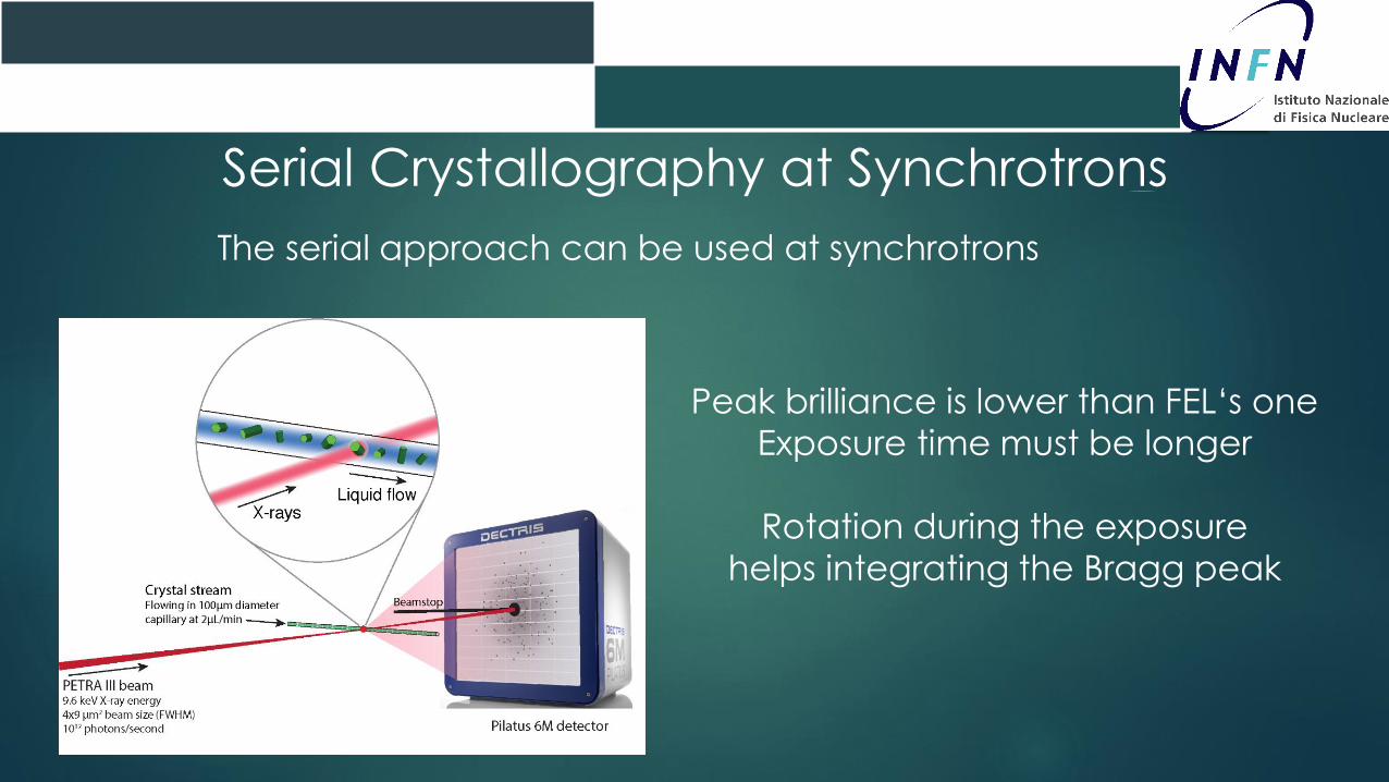
Serial Crystallography at Synchrotrons
The serial approach can be used at synchrotrons
Peak brilliance is lower than FEL‘s one
Exposure time must be longer
Rotation during the exposure
helps integrating the Bragg peak
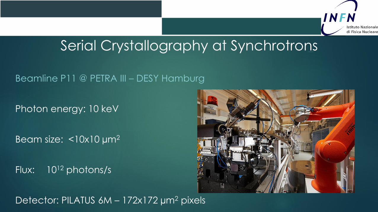
Serial Crystallography at Synchrotrons
Beamline P11 @ PETRA III – DESY Hamburg
Photon energy: 10 keV
Beam size: <10x10 µm2
Flux: 1012 photons/s
Detector: PILATUS 6M – 172x172 µm2 pixels
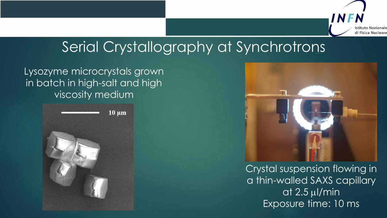
Serial Crystallography at Synchrotrons
Lysozyme microcrystals grown
in batch in high-salt and high
viscosity medium
Crystal suspension flowing in
a thin-walled SAXS capillary
at 2.5 l/min
Exposure time: 10 ms

Serial Crystallography at Synchrotrons
> 1,000,000 recorded patterns
Hit-finding
150,000 ‘hits’
Indexing
40,000 indexed patterns
2.1 Å
Bragg spots visibleup to 2 Åresolution

Serial Crystallography at Synchrotrons
Lysozyme structure solved at2.1Å resolution by molecular
replacement merging
intensities from
40,000 single crystal diffraction
patterns
Pdb ID: 4O34Stellato F. et al., IUCrJ 2014
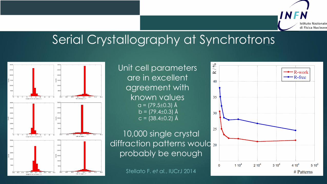
Serial Crystallography at Synchrotrons
Unit cell parameters
are in excellent
agreement with
known valuesa = (79.50.3) Åb = (79.40.3) Åc = (38.40.2) Å
10,000 single crystal
diffraction patterns would
probably be enough
Stellato F. et al., IUCrJ 2014
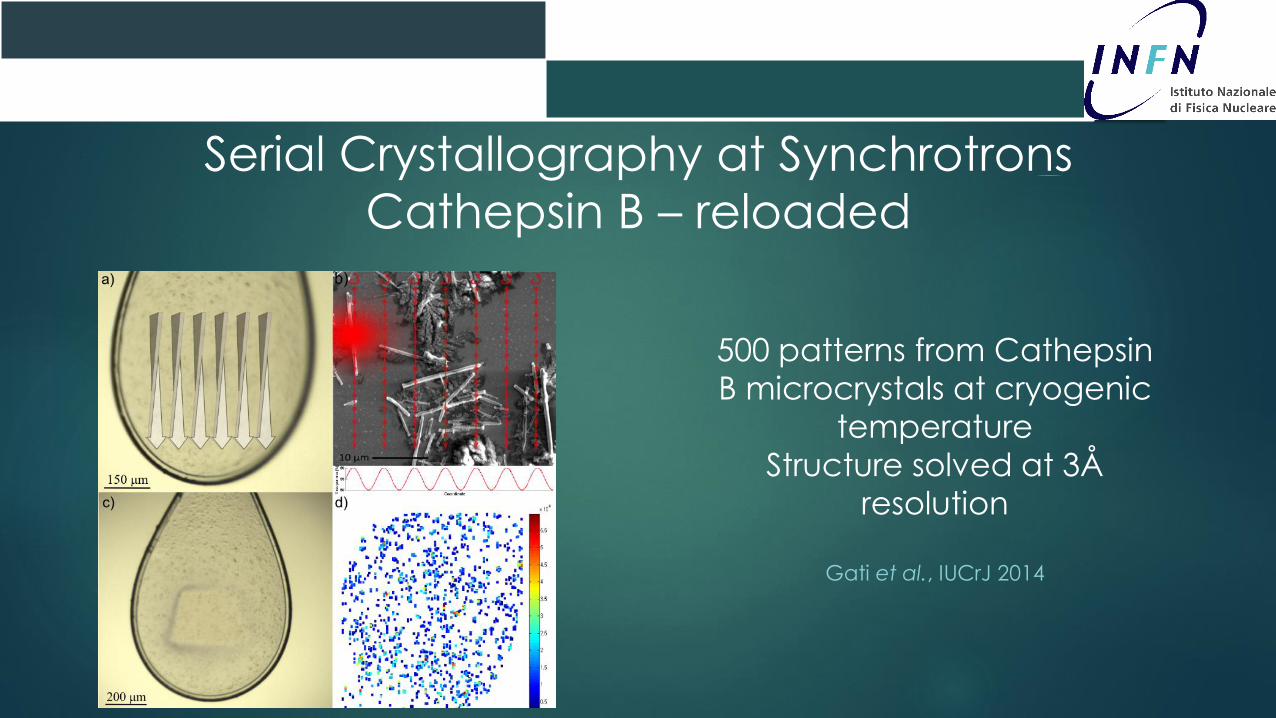
Serial Crystallography at Synchrotrons
Cathepsin B – reloaded
500 patterns from Cathepsin
B microcrystals at cryogenic
temperature
Structure solved at 3Å
resolution
Gati et al., IUCrJ 2014
Applications & Future Perspectives
- Time-resolved measurements
- Sample delivery optimized for different media
- 2D crystallography
- Spectroscopies
Luci di Sincrotrone
CNR – Roma, 22 Aprile 2014
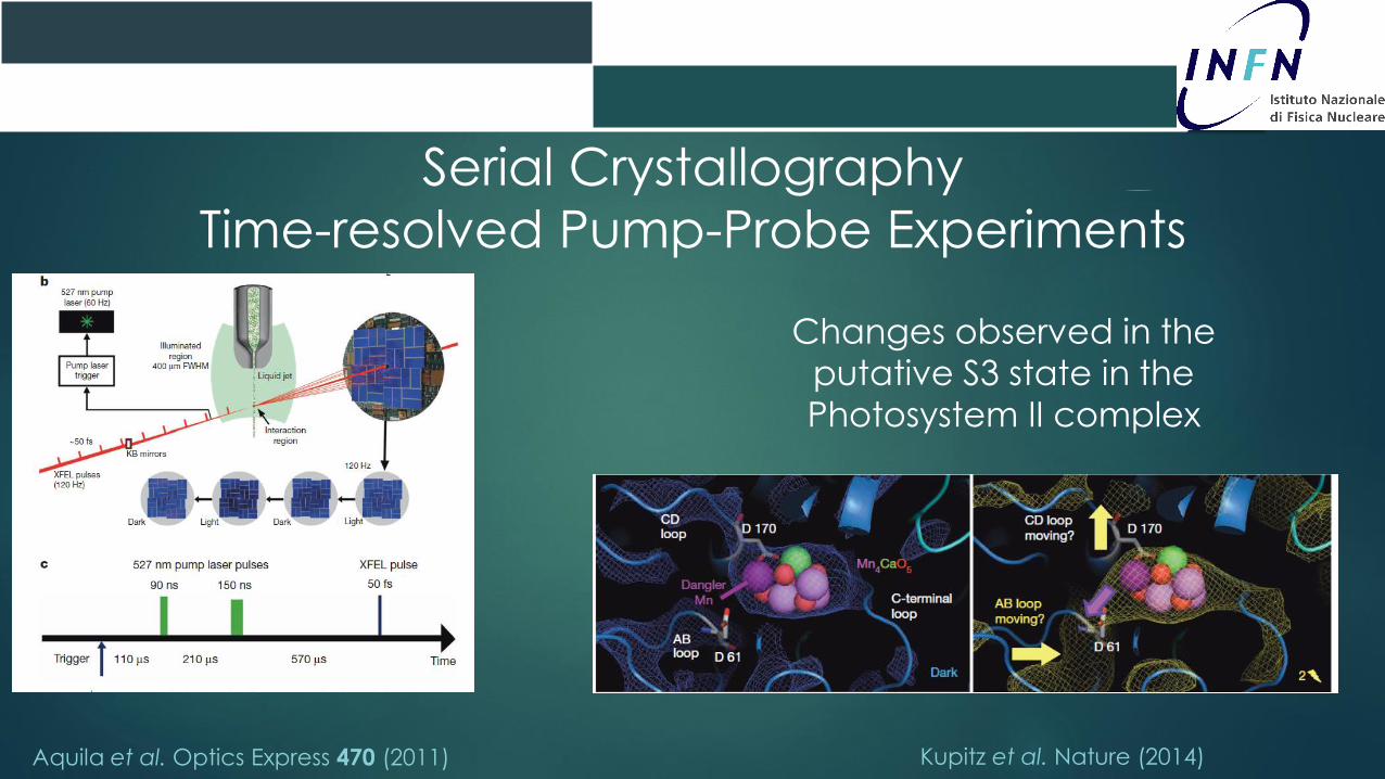
Serial Crystallography
Time-resolved Pump-Probe Experiments
Aquila et al. Optics Express 470 (2011) Kupitz et al. Nature (2014)
Changes observed in the
putative S3 state in the
Photosystem II complex
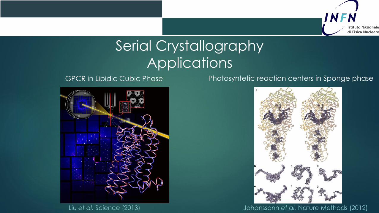
Serial Crystallography
ApplicationsGPCR in Lipidic Cubic Phase
Liu et al. Science (2013) Johanssonn et al. Nature Methods (2012)
Photosyntetic reaction centers in Sponge phase
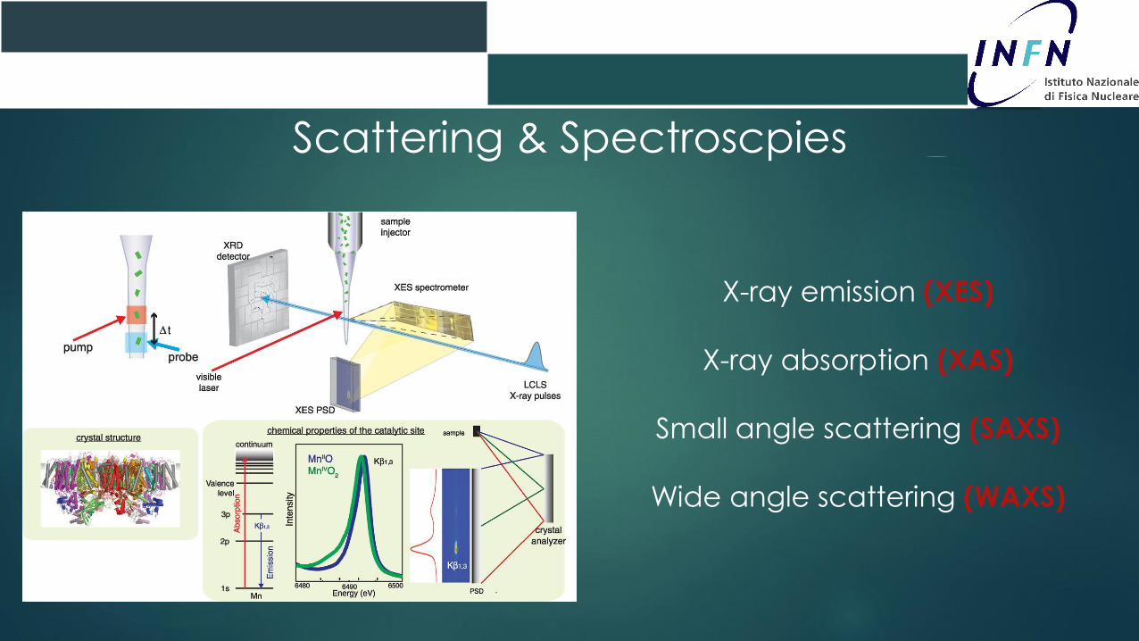
Scattering & Spectroscpies
X-ray emission (XES)
X-ray absorption (XAS)
Small angle scattering (SAXS)
Wide angle scattering (WAXS)

Outlook
- Less beamtime: higher repetition rate FELs (XFEL)
- More sources: brighter sinchrotrons (ESRF, PETRA III)
- Less sample: improved sample injection systems
- More science: time-resolved experiments on different proteins
Higher and higher brilliance will
enable approaching the limit of
high-resolution single molecule
imaging
Luci di Sincrotrone
CNR – Roma, 22 Aprile 2014

Acknowledgements
The Biophysics Group in Tor Vergata
biophys.roma2.infn.it
Silvia Morante
Giancarlo Rossi
Velia Minicozzi
Francesco Stellato
Marco Pascucci
Claudia Narcisi
Emiliano De Santis
CFEL-DESY
H. Chapman, J. Schulz, A. Barty, M. Liang, A. Aquila, T. White, D. Deponte, S. Bajt, M. Barthelmess, A. Martin, C. Caleman, K.
Nass, F. Stellato, H. Fleckenstein, L. Galli, R. Kirian, K. Beyerlein
Arizona State Univeristy
J. Spence, P. Fromme, U. Weierstall, B. Doak, M. Hunter, C. Kupitz
SLAC
M. Bogan, S. Boutet, G. Williams, D. Starodub, R. Sierra, C. Hampton, J. Kryzwinski, C. Bostedt, M. Messerschmidt
Uppsala Univeristy
J. Hajdu, Nic Timneanu, J. Andreasson, M. Seibert, F. Maia, M. Svenda, T. Ekeberg, J. Andreasson, A. Rocker, O. Jonsson, D.
Westphal
University of Tübingen, Hamburg and Lübeck
C. Betzel, L. Redecke, D. Rehders, K. Cupelli, R. Koopmann, M. Duszenko, T. Stehle
Max Planck Heidelberg, LBNL, LLNL
European XFEL Massimo Altarellii
Thank you for
the attention
Contacts
Francesco Stellato
I.N.F.N. Sezione di Roma Tor Vergata
Via della Ricerca Scientifica, 1
Tel: 0039 06 7259 4284