series 3700vmpd hot melt material applicator -...
TRANSCRIPT

Series 3700VMPDHot Melt Material Applicator
with DC Pump, L Manifold,and Vista� Controller
Customer Product ManualPart 1015471B
NORDSON CORPORATION � Duluth, Georgiawww.nordson.com
� 2002 Nordson CorporationAll rights reserved
1015471BIssued 10/02
Nordson Corporation welcomes requests for information, comments and inquiries about its products. Generalinformation about Nordson can be found on the Internet using the following address: http://www.nordson.com.
Address all correspondence to:
Nordson CorporationAttn: Customer Service11475 Lakefield Drive
Duluth, GA 30097
Notice
This is a Nordson Corporation publication which is protected by copyright. Original copyright date 2001. No part of this document may be photocopied, reproduced, or translated to another language without the prior written
consent of Nordson Corporation. The information contained in this publication is subject to change without notice.
Trademarks
AccuJet, AquaGuard, Asymtek, Automove, Autotech, Blue Box, CF, CanWorks, Century, Clean Coat, CleanSleeve,CleanSpray, Compumelt, Control Coat, Cross-Cut, Cyclo-Kinetic, Dispensejet, DispenseMate, Durafiber, Durasystem,Easy Coat, Easymove Plus, Econo-Coat, EPREG, ETI, Excel 2000, Flex-O-Coat, FlexiCoat, Flexi-Spray, Flow Sentry,
Fluidmove, Fluidshooter, FoamMelt, FoamMix, Helix, Horizon, Hose Mole, Hot Shot, Hot Stitch, Isocoil, Isocore, Iso-Flo, JR,KB30, Little Squirt, Magnastatic, MEG, Meltex, MicroSet, Millenium, Mini Squirt, Moist-Cure, Mountaingate, MultiScan,
Nordson, OmniScan, Opticoat, Package of Values, PluraFoam, Porous Coat, PowderGrid, Powderware, Pro-Flo, ProLink,Pro-Meter, Pro-Stream, PRX, RBX, Ready Cost, Rhino, S. design stylized, Saturn, SC5, SCF, Select Charge, Select Coat,Select Cure, Shur-Lok, Slautterback, Smart-Coat, Spray Squirt, Spraymelt, Super Squirt, Sure-Bond, Sure Coat, System
Sentry, Tela-Therm, Trends, Tribomatic, UniScan, UpTime, Veritec, Versa-Coat, Versa-Screen, Versa-Spray, Watermark, andWhen you expect more. are registered trademarks – � – of Nordson Corporation.
ATS, Auto-Flo, AutoScan, BetterBook, Chameleon, CanNeck, Check Mate, CPX, Control Weave, Controlled Fiberization,EasyClean, Ebraid, Eclipse, Equi=Bead, Fillmaster, Gluie, Ink-Dot, Maxima, MicroFin, Minimeter, Multifil, OptiMix,
Pattern View, PluraMix, Primarc, Prism, Process Sentry, PurTech, Pulse Spray, Seal Sentry, Select Series, Sensomatic,Shaftshield, Spectral, Spectrum, Sure Brand, Swirl Coat, Vista, Walcom, and 2 Rings (Design)
are trademarks – � – of Nordson Corporation. Viton is a registered trademark of DuPont Dow Elastomers.
Table of Contents i
� 2002 Nordson CorporationAll rights reserved
1015471BIssued 10/02
Manual41-3700-MPD-MA-01
Table of Contents
1. Operate Safely 1-1. . . . . . . . . . . . . . . . . . . . . . . . . . . . . . . . . . . . . . . . . . . .
2. Safety Symbols 1-2. . . . . . . . . . . . . . . . . . . . . . . . . . . . . . . . . . . . . . . . . . .
3. Qualified Personnel 1-2. . . . . . . . . . . . . . . . . . . . . . . . . . . . . . . . . . . . . . .
4. Intended Use 1-3. . . . . . . . . . . . . . . . . . . . . . . . . . . . . . . . . . . . . . . . . . . . .
5. Installation and Electrical Connections 1-4. . . . . . . . . . . . . . . . . . . . . . .
6. Operation 1-4. . . . . . . . . . . . . . . . . . . . . . . . . . . . . . . . . . . . . . . . . . . . . . . .
Less-Obvious Dangers 1-5. . . . . . . . . . . . . . . . . . . . . . . . . . . . . . . .
Action in the Event of Unit Malfunction 1-5. . . . . . . . . . . . . . . . . .
Danger of Burns 1-6. . . . . . . . . . . . . . . . . . . . . . . . . . . . . . . . . . . . . .
7. Maintenance/Repair 1-6. . . . . . . . . . . . . . . . . . . . . . . . . . . . . . . . . . . . . . .
8. Cleaning 1-7. . . . . . . . . . . . . . . . . . . . . . . . . . . . . . . . . . . . . . . . . . . . . . . . .
9. Thermoplastic Hot Melt Material 1-8. . . . . . . . . . . . . . . . . . . . . . . . . . . . .
10. Equipment and Material Disposal 1-8. . . . . . . . . . . . . . . . . . . . . . . . . . . .
1. Introduction 2-1. . . . . . . . . . . . . . . . . . . . . . . . . . . . . . . . . . . . . . . . . . . . . . .
2. Functional Operation 2-2. . . . . . . . . . . . . . . . . . . . . . . . . . . . . . . . . . . . . .
Startup Mode 2-2. . . . . . . . . . . . . . . . . . . . . . . . . . . . . . . . . . . . . . . . . . .
Operating Mode 2-2. . . . . . . . . . . . . . . . . . . . . . . . . . . . . . . . . . . . . . . .
Standby Mode 2-2. . . . . . . . . . . . . . . . . . . . . . . . . . . . . . . . . . . . . . . . . .
3. Overview of the Mechanical Components 2-4. . . . . . . . . . . . . . . . . . . .
Tank 2-4. . . . . . . . . . . . . . . . . . . . . . . . . . . . . . . . . . . . . . . . . . . . . . . . . .
Pump 2-4. . . . . . . . . . . . . . . . . . . . . . . . . . . . . . . . . . . . . . . . . . . . . . . . .
Manifold 2-5. . . . . . . . . . . . . . . . . . . . . . . . . . . . . . . . . . . . . . . . . . . . . . .
Operator Panel 2-6. . . . . . . . . . . . . . . . . . . . . . . . . . . . . . . . . . . . . . . . .
Section 1Safety
Section 2Description
Table of Contentsii
� 2002 Nordson CorporationAll rights reserved
1015471BIssued 10/02
Manual41-3700-MPD-MA-01
4. Control System 2-6. . . . . . . . . . . . . . . . . . . . . . . . . . . . . . . . . . . . . . . . . . .
Features of the Operator Panel 2-7. . . . . . . . . . . . . . . . . . . . . . . . .
System Status Area 2-8. . . . . . . . . . . . . . . . . . . . . . . . . . . . . . . . . . . . .
FAULT Light 2-8. . . . . . . . . . . . . . . . . . . . . . . . . . . . . . . . . . . . . . . . . . . .
READY Light 2-9. . . . . . . . . . . . . . . . . . . . . . . . . . . . . . . . . . . . . . . .
Displays Area 2-9. . . . . . . . . . . . . . . . . . . . . . . . . . . . . . . . . . . . . . . . . .
Selector Display and Up Key 2-10. . . . . . . . . . . . . . . . . . . . . . . . . .
Multipurpose Display and Keys 2-10. . . . . . . . . . . . . . . . . . . . . . . .
Actual Temperature Display 2-10. . . . . . . . . . . . . . . . . . . . . . . . . . .
Enter Key 2-10. . . . . . . . . . . . . . . . . . . . . . . . . . . . . . . . . . . . . . . . . .
System Setup Area 2-11. . . . . . . . . . . . . . . . . . . . . . . . . . . . . . . . . . . .
Up and Down Keys 2-11. . . . . . . . . . . . . . . . . . . . . . . . . . . . . . . . . .
Right Key 2-11. . . . . . . . . . . . . . . . . . . . . . . . . . . . . . . . . . . . . . . . . . .
TEMPERATURE Area 2-12. . . . . . . . . . . . . . . . . . . . . . . . . . . . . . . .
SYSTEM SETTINGS Area 2-12. . . . . . . . . . . . . . . . . . . . . . . . . . . .
CLOCK Area 2-13. . . . . . . . . . . . . . . . . . . . . . . . . . . . . . . . . . . . . . . .
System Controls Area 2-13. . . . . . . . . . . . . . . . . . . . . . . . . . . . . . . . . .
MONITOR/SCAN Key and Light 2-14. . . . . . . . . . . . . . . . . . . . . . .
STANDBY Key and Light 2-15. . . . . . . . . . . . . . . . . . . . . . . . . . . . .
HEATERS Key and Light 2-15. . . . . . . . . . . . . . . . . . . . . . . . . . . . .
CLOCK Key and Light 2-16. . . . . . . . . . . . . . . . . . . . . . . . . . . . . . . .
PUMP Key and Light 2-16. . . . . . . . . . . . . . . . . . . . . . . . . . . . . . . . .
CLEAR FAULTS Key 2-16. . . . . . . . . . . . . . . . . . . . . . . . . . . . . . . . .
POWER Switch 2-16. . . . . . . . . . . . . . . . . . . . . . . . . . . . . . . . . . . . .
1. Introduction 3-1. . . . . . . . . . . . . . . . . . . . . . . . . . . . . . . . . . . . . . . . . . . . . . .
2. Inspection 3-1. . . . . . . . . . . . . . . . . . . . . . . . . . . . . . . . . . . . . . . . . . . . . . . .
3. Installation Guidelines 3-1. . . . . . . . . . . . . . . . . . . . . . . . . . . . . . . . . . . . .
Installation Location 3-1. . . . . . . . . . . . . . . . . . . . . . . . . . . . . . . . . . . . .
Wiring Requirements 3-2. . . . . . . . . . . . . . . . . . . . . . . . . . . . . . . . . . . .
Hose/Gun Power Requirements 3-2. . . . . . . . . . . . . . . . . . . . . . . . . .
4. Melter Installation 3-3. . . . . . . . . . . . . . . . . . . . . . . . . . . . . . . . . . . . . . . . .
Mounting the Melter 3-3. . . . . . . . . . . . . . . . . . . . . . . . . . . . . . . . . . . . .
Installing the Tank Strainer 3-4. . . . . . . . . . . . . . . . . . . . . . . . . . . . . . .
Section 2Description (contd)
Section 3Installation
Table of Contents iii
� 2002 Nordson CorporationAll rights reserved
1015471BIssued 10/02
Manual41-3700-MPD-MA-01
5. Hose and Gun Installation 3-5. . . . . . . . . . . . . . . . . . . . . . . . . . . . . . . . . .
Installing Guns 3-5. . . . . . . . . . . . . . . . . . . . . . . . . . . . . . . . . . . . . . . . .
Installing Hoses 3-5. . . . . . . . . . . . . . . . . . . . . . . . . . . . . . . . . . . . . . . . .
6. Electrical Installation 3-7. . . . . . . . . . . . . . . . . . . . . . . . . . . . . . . . . . . . . . .
Opening the Electrical Enclosure 3-8. . . . . . . . . . . . . . . . . . . . . . . . . .
Input/Output Board 3-9. . . . . . . . . . . . . . . . . . . . . . . . . . . . . . . . . . . . . .
Making the Input/Output Board Connections 3-9. . . . . . . . . . . . . . . .
Connecting Output Contacts (Optional) 3-13. . . . . . . . . . . . . . . . . . .
Connecting Electrical Service 3-15. . . . . . . . . . . . . . . . . . . . . . . . . . . .
Closing the Electrical Enclosure 3-19. . . . . . . . . . . . . . . . . . . . . . . . .
7. Air Supply Installation 3-20. . . . . . . . . . . . . . . . . . . . . . . . . . . . . . . . . . . . .
8. System Programming Procedures 3-21. . . . . . . . . . . . . . . . . . . . . . . . . .
Programming System Controls 3-22. . . . . . . . . . . . . . . . . . . . . . . . . .
Programming SYSTEM SETTINGS Controls 3-24. . . . . . . . . . . . . .
Programming TEMPERATURE Controls 3-29. . . . . . . . . . . . . . . . . .
To Program All Zones to the Same Temperature 3-31. . . . . . . . .
To Program Setpoint and Standby Temperatures Individually . . .
3-33. . . . . . . . . . . . . . . . . . . . . . . . . . . . . . . . . . . . . . . . . . . . . . . . . . . .
Programming CLOCK Controls 3-35. . . . . . . . . . . . . . . . . . . . . . . . . .
To Set the Clock 3-35. . . . . . . . . . . . . . . . . . . . . . . . . . . . . . . . . . . . .
To Set Standby and Heater Times 3-38. . . . . . . . . . . . . . . . . . . . .
To Change a Standby or Heater Time 3-40. . . . . . . . . . . . . . . . . .
To Delete a Standby or Heater Time 3-41. . . . . . . . . . . . . . . . . . .
To Delete Times for an Entire Day 3-41. . . . . . . . . . . . . . . . . . . . .
An Example of How to Use the Seven-Day Clock Feature 3-42
9. System Preparation 3-43. . . . . . . . . . . . . . . . . . . . . . . . . . . . . . . . . . . . . .
10. Records of System Settings 3-44. . . . . . . . . . . . . . . . . . . . . . . . . . . . . . .
Record of SETPOINT (Operating) Temperature Settings 3-44. . . .
Record of Standby Temperature Settings 3-45. . . . . . . . . . . . . . . . .
Record of Set Times for Heaters On and Heaters Off 3-46. . . . . . .
Record of Set Times for Entering and Exiting Standby 3-47. . . . . .
Record of Customized System Settings Features 3-48. . . . . . . . . .
Record of Air Pressure Settings 3-49. . . . . . . . . . . . . . . . . . . . . . . . . .
Record of System Faults 3-50. . . . . . . . . . . . . . . . . . . . . . . . . . . . . . . .
Record of System Warnings 3-51. . . . . . . . . . . . . . . . . . . . . . . . . . . . .
Section 3Installation (contd)
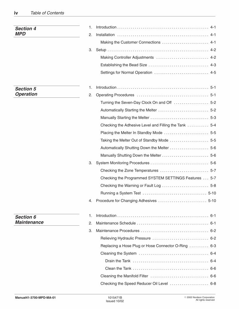
Table of Contentsiv
� 2002 Nordson CorporationAll rights reserved
1015471BIssued 10/02
Manual41-3700-MPD-MA-01
1. Introduction 4-1. . . . . . . . . . . . . . . . . . . . . . . . . . . . . . . . . . . . . . . . . . . . . . .
2. Installation 4-1. . . . . . . . . . . . . . . . . . . . . . . . . . . . . . . . . . . . . . . . . . . . . . .
Making the Customer Connections 4-1. . . . . . . . . . . . . . . . . . . . . . . .
3. Setup 4-2. . . . . . . . . . . . . . . . . . . . . . . . . . . . . . . . . . . . . . . . . . . . . . . . . . . .
Making Controller Adjustments 4-2. . . . . . . . . . . . . . . . . . . . . . . . . . .
Establishing the Bead Size 4-3. . . . . . . . . . . . . . . . . . . . . . . . . . . . . . .
Settings for Normal Operation 4-5. . . . . . . . . . . . . . . . . . . . . . . . . . . .
1. Introduction 5-1. . . . . . . . . . . . . . . . . . . . . . . . . . . . . . . . . . . . . . . . . . . . . . .
2. Operating Procedures 5-1. . . . . . . . . . . . . . . . . . . . . . . . . . . . . . . . . . . . .
Turning the Seven-Day Clock On and Off 5-2. . . . . . . . . . . . . . . . . .
Automatically Starting the Melter 5-2. . . . . . . . . . . . . . . . . . . . . . . . . .
Manually Starting the Melter 5-3. . . . . . . . . . . . . . . . . . . . . . . . . . . . . .
Checking the Adhesive Level and Filling the Tank 5-4. . . . . . . . . . .
Placing the Melter In Standby Mode 5-5. . . . . . . . . . . . . . . . . . . . . . .
Taking the Melter Out of Standby Mode 5-5. . . . . . . . . . . . . . . . . . . .
Automatically Shutting Down the Melter 5-6. . . . . . . . . . . . . . . . . . . .
Manually Shutting Down the Melter 5-6. . . . . . . . . . . . . . . . . . . . . . . .
3. System Monitoring Procedures 5-6. . . . . . . . . . . . . . . . . . . . . . . . . . . . . .
Checking the Zone Temperatures 5-7. . . . . . . . . . . . . . . . . . . . . . . . .
Checking the Programmed SYSTEM SETTINGS Features 5-7. . .
Checking the Warning or Fault Log 5-8. . . . . . . . . . . . . . . . . . . . . . . .
Running a System Test 5-10. . . . . . . . . . . . . . . . . . . . . . . . . . . . . . . . .
4. Procedure for Changing Adhesives 5-10. . . . . . . . . . . . . . . . . . . . . . . . .
1. Introduction 6-1. . . . . . . . . . . . . . . . . . . . . . . . . . . . . . . . . . . . . . . . . . . . . . .
2. Maintenance Schedule 6-1. . . . . . . . . . . . . . . . . . . . . . . . . . . . . . . . . . . . .
3. Maintenance Procedures 6-2. . . . . . . . . . . . . . . . . . . . . . . . . . . . . . . . . . .
Relieving Hydraulic Pressure 6-2. . . . . . . . . . . . . . . . . . . . . . . . . . . . .
Replacing a Hose Plug or Hose Connector O-Ring 6-3. . . . . . . . . .
Cleaning the System 6-4. . . . . . . . . . . . . . . . . . . . . . . . . . . . . . . . . . . .
Drain the Tank 6-4. . . . . . . . . . . . . . . . . . . . . . . . . . . . . . . . . . . . . . .
Clean the Tank 6-6. . . . . . . . . . . . . . . . . . . . . . . . . . . . . . . . . . . . . . .
Cleaning the Manifold Filter 6-6. . . . . . . . . . . . . . . . . . . . . . . . . . . . . .
Checking the Speed Reducer Oil Level 6-8. . . . . . . . . . . . . . . . . . . .
Section 4MPD
Section 5Operation
Section 6Maintenance
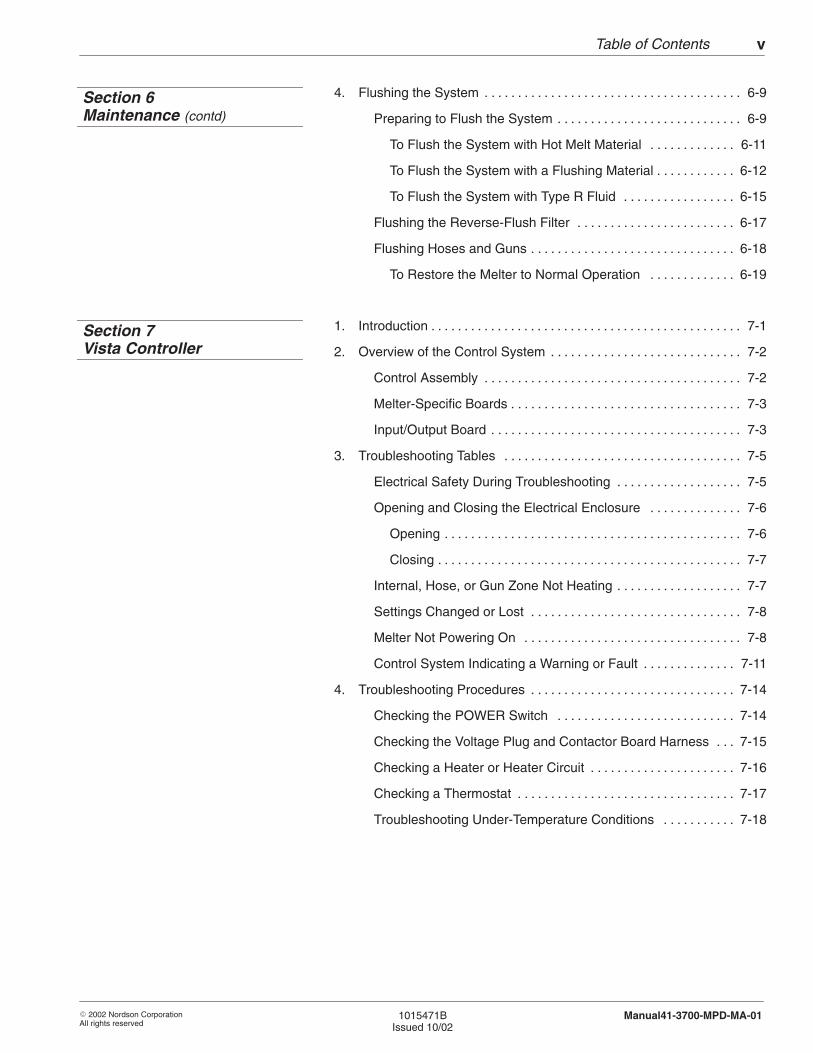
Table of Contents v
� 2002 Nordson CorporationAll rights reserved
1015471BIssued 10/02
Manual41-3700-MPD-MA-01
4. Flushing the System 6-9. . . . . . . . . . . . . . . . . . . . . . . . . . . . . . . . . . . . . . .
Preparing to Flush the System 6-9. . . . . . . . . . . . . . . . . . . . . . . . . . . .
To Flush the System with Hot Melt Material 6-11. . . . . . . . . . . . .
To Flush the System with a Flushing Material 6-12. . . . . . . . . . . .
To Flush the System with Type R Fluid 6-15. . . . . . . . . . . . . . . . .
Flushing the Reverse-Flush Filter 6-17. . . . . . . . . . . . . . . . . . . . . . . .
Flushing Hoses and Guns 6-18. . . . . . . . . . . . . . . . . . . . . . . . . . . . . . .
To Restore the Melter to Normal Operation 6-19. . . . . . . . . . . . .
1. Introduction 7-1. . . . . . . . . . . . . . . . . . . . . . . . . . . . . . . . . . . . . . . . . . . . . . .
2. Overview of the Control System 7-2. . . . . . . . . . . . . . . . . . . . . . . . . . . . .
Control Assembly 7-2. . . . . . . . . . . . . . . . . . . . . . . . . . . . . . . . . . . . . . .
Melter-Specific Boards 7-3. . . . . . . . . . . . . . . . . . . . . . . . . . . . . . . . . . .
Input/Output Board 7-3. . . . . . . . . . . . . . . . . . . . . . . . . . . . . . . . . . . . . .
3. Troubleshooting Tables 7-5. . . . . . . . . . . . . . . . . . . . . . . . . . . . . . . . . . . .
Electrical Safety During Troubleshooting 7-5. . . . . . . . . . . . . . . . . . .
Opening and Closing the Electrical Enclosure 7-6. . . . . . . . . . . . . .
Opening 7-6. . . . . . . . . . . . . . . . . . . . . . . . . . . . . . . . . . . . . . . . . . . . .
Closing 7-7. . . . . . . . . . . . . . . . . . . . . . . . . . . . . . . . . . . . . . . . . . . . . .
Internal, Hose, or Gun Zone Not Heating 7-7. . . . . . . . . . . . . . . . . . .
Settings Changed or Lost 7-8. . . . . . . . . . . . . . . . . . . . . . . . . . . . . . . .
Melter Not Powering On 7-8. . . . . . . . . . . . . . . . . . . . . . . . . . . . . . . . .
Control System Indicating a Warning or Fault 7-11. . . . . . . . . . . . . .
4. Troubleshooting Procedures 7-14. . . . . . . . . . . . . . . . . . . . . . . . . . . . . . .
Checking the POWER Switch 7-14. . . . . . . . . . . . . . . . . . . . . . . . . . .
Checking the Voltage Plug and Contactor Board Harness 7-15. . .
Checking a Heater or Heater Circuit 7-16. . . . . . . . . . . . . . . . . . . . . .
Checking a Thermostat 7-17. . . . . . . . . . . . . . . . . . . . . . . . . . . . . . . . .
Troubleshooting Under-Temperature Conditions 7-18. . . . . . . . . . .
Section 6Maintenance (contd)
Section 7Vista Controller
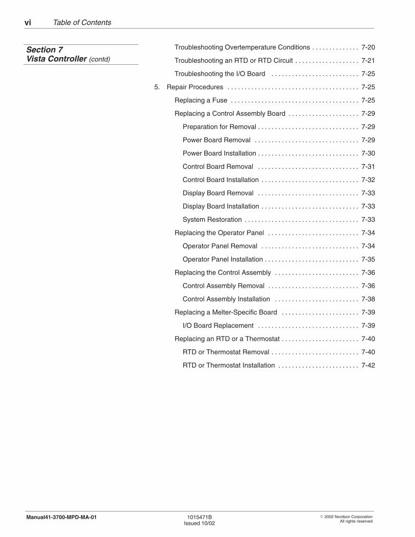
Table of Contentsvi
� 2002 Nordson CorporationAll rights reserved
1015471BIssued 10/02
Manual41-3700-MPD-MA-01
Troubleshooting Overtemperature Conditions 7-20. . . . . . . . . . . . . .
Troubleshooting an RTD or RTD Circuit 7-21. . . . . . . . . . . . . . . . . . .
Troubleshooting the I/O Board 7-25. . . . . . . . . . . . . . . . . . . . . . . . . .
5. Repair Procedures 7-25. . . . . . . . . . . . . . . . . . . . . . . . . . . . . . . . . . . . . . .
Replacing a Fuse 7-25. . . . . . . . . . . . . . . . . . . . . . . . . . . . . . . . . . . . . .
Replacing a Control Assembly Board 7-29. . . . . . . . . . . . . . . . . . . . .
Preparation for Removal 7-29. . . . . . . . . . . . . . . . . . . . . . . . . . . . . .
Power Board Removal 7-29. . . . . . . . . . . . . . . . . . . . . . . . . . . . . . .
Power Board Installation 7-30. . . . . . . . . . . . . . . . . . . . . . . . . . . . . .
Control Board Removal 7-31. . . . . . . . . . . . . . . . . . . . . . . . . . . . . .
Control Board Installation 7-32. . . . . . . . . . . . . . . . . . . . . . . . . . . . .
Display Board Removal 7-33. . . . . . . . . . . . . . . . . . . . . . . . . . . . . .
Display Board Installation 7-33. . . . . . . . . . . . . . . . . . . . . . . . . . . . .
System Restoration 7-33. . . . . . . . . . . . . . . . . . . . . . . . . . . . . . . . . .
Replacing the Operator Panel 7-34. . . . . . . . . . . . . . . . . . . . . . . . . . .
Operator Panel Removal 7-34. . . . . . . . . . . . . . . . . . . . . . . . . . . . .
Operator Panel Installation 7-35. . . . . . . . . . . . . . . . . . . . . . . . . . . .
Replacing the Control Assembly 7-36. . . . . . . . . . . . . . . . . . . . . . . . .
Control Assembly Removal 7-36. . . . . . . . . . . . . . . . . . . . . . . . . . .
Control Assembly Installation 7-38. . . . . . . . . . . . . . . . . . . . . . . . .
Replacing a Melter-Specific Board 7-39. . . . . . . . . . . . . . . . . . . . . . .
I/O Board Replacement 7-39. . . . . . . . . . . . . . . . . . . . . . . . . . . . . .
Replacing an RTD or a Thermostat 7-40. . . . . . . . . . . . . . . . . . . . . . .
RTD or Thermostat Removal 7-40. . . . . . . . . . . . . . . . . . . . . . . . . .
RTD or Thermostat Installation 7-42. . . . . . . . . . . . . . . . . . . . . . . .
Section 7Vista Controller (contd)
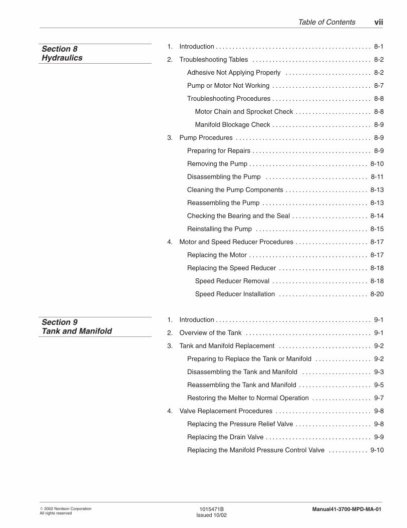
Table of Contents vii
� 2002 Nordson CorporationAll rights reserved
1015471BIssued 10/02
Manual41-3700-MPD-MA-01
1. Introduction 8-1. . . . . . . . . . . . . . . . . . . . . . . . . . . . . . . . . . . . . . . . . . . . . . .
2. Troubleshooting Tables 8-2. . . . . . . . . . . . . . . . . . . . . . . . . . . . . . . . . . . .
Adhesive Not Applying Properly 8-2. . . . . . . . . . . . . . . . . . . . . . . . . .
Pump or Motor Not Working 8-7. . . . . . . . . . . . . . . . . . . . . . . . . . . . . .
Troubleshooting Procedures 8-8. . . . . . . . . . . . . . . . . . . . . . . . . . . . . .
Motor Chain and Sprocket Check 8-8. . . . . . . . . . . . . . . . . . . . . . .
Manifold Blockage Check 8-9. . . . . . . . . . . . . . . . . . . . . . . . . . . . . .
3. Pump Procedures 8-9. . . . . . . . . . . . . . . . . . . . . . . . . . . . . . . . . . . . . . . . .
Preparing for Repairs 8-9. . . . . . . . . . . . . . . . . . . . . . . . . . . . . . . . . . . .
Removing the Pump 8-10. . . . . . . . . . . . . . . . . . . . . . . . . . . . . . . . . . . .
Disassembling the Pump 8-11. . . . . . . . . . . . . . . . . . . . . . . . . . . . . . .
Cleaning the Pump Components 8-13. . . . . . . . . . . . . . . . . . . . . . . . .
Reassembling the Pump 8-13. . . . . . . . . . . . . . . . . . . . . . . . . . . . . . . .
Checking the Bearing and the Seal 8-14. . . . . . . . . . . . . . . . . . . . . . .
Reinstalling the Pump 8-15. . . . . . . . . . . . . . . . . . . . . . . . . . . . . . . . . .
4. Motor and Speed Reducer Procedures 8-17. . . . . . . . . . . . . . . . . . . . . .
Replacing the Motor 8-17. . . . . . . . . . . . . . . . . . . . . . . . . . . . . . . . . . . .
Replacing the Speed Reducer 8-18. . . . . . . . . . . . . . . . . . . . . . . . . . .
Speed Reducer Removal 8-18. . . . . . . . . . . . . . . . . . . . . . . . . . . . .
Speed Reducer Installation 8-20. . . . . . . . . . . . . . . . . . . . . . . . . . .
1. Introduction 9-1. . . . . . . . . . . . . . . . . . . . . . . . . . . . . . . . . . . . . . . . . . . . . . .
2. Overview of the Tank 9-1. . . . . . . . . . . . . . . . . . . . . . . . . . . . . . . . . . . . . .
3. Tank and Manifold Replacement 9-2. . . . . . . . . . . . . . . . . . . . . . . . . . . .
Preparing to Replace the Tank or Manifold 9-2. . . . . . . . . . . . . . . . .
Disassembling the Tank and Manifold 9-3. . . . . . . . . . . . . . . . . . . . .
Reassembling the Tank and Manifold 9-5. . . . . . . . . . . . . . . . . . . . . .
Restoring the Melter to Normal Operation 9-7. . . . . . . . . . . . . . . . . .
4. Valve Replacement Procedures 9-8. . . . . . . . . . . . . . . . . . . . . . . . . . . . .
Replacing the Pressure Relief Valve 9-8. . . . . . . . . . . . . . . . . . . . . . .
Replacing the Drain Valve 9-9. . . . . . . . . . . . . . . . . . . . . . . . . . . . . . . .
Replacing the Manifold Pressure Control Valve 9-10. . . . . . . . . . . .
Section 8Hydraulics
Section 9Tank and Manifold
Table of Contentsviii
� 2002 Nordson CorporationAll rights reserved
1015471BIssued 10/02
Manual41-3700-MPD-MA-01
1. Introduction 10-1. . . . . . . . . . . . . . . . . . . . . . . . . . . . . . . . . . . . . . . . . . . . . .
2. Use of Wiring Diagrams 10-1. . . . . . . . . . . . . . . . . . . . . . . . . . . . . . . . . . .
1. Introduction 11-1. . . . . . . . . . . . . . . . . . . . . . . . . . . . . . . . . . . . . . . . . . . . . .
Using the Illustrated Parts List 11-1. . . . . . . . . . . . . . . . . . . . . . . . . . .
2. Control Assembly Parts List 11-2. . . . . . . . . . . . . . . . . . . . . . . . . . . . . . .
Melter-Specific Parts List 11-4. . . . . . . . . . . . . . . . . . . . . . . . . . . . . . .
3. Pump Assembly Parts List 11-6. . . . . . . . . . . . . . . . . . . . . . . . . . . . . . . . .
Service Kits 11-8. . . . . . . . . . . . . . . . . . . . . . . . . . . . . . . . . . . . . . . . . . .
UpTime Packs 11-8. . . . . . . . . . . . . . . . . . . . . . . . . . . . . . . . . . . . . . . . .
Recommended Spare Parts for DC Pumps 11-8. . . . . . . . . . . . . . . .
Air Pressure Regulator and Filter Assembly Parts List 11-9. . . . . .
4. Melter Assembly Parts List 11-10. . . . . . . . . . . . . . . . . . . . . . . . . . . . . . .
Melter Assembly Service Kits 11-14. . . . . . . . . . . . . . . . . . . . . . . . . . .
Ground Stud Assembly Parts List 11-15. . . . . . . . . . . . . . . . . . . . . . .
5. Manifold Assembly Parts List 11-16. . . . . . . . . . . . . . . . . . . . . . . . . . . . .
Manifold Filter Parts List 11-18. . . . . . . . . . . . . . . . . . . . . . . . . . . . . . .
Manifold Assembly Service Kits 11-19. . . . . . . . . . . . . . . . . . . . . . . . .
Manifold Filter Service Kits 11-19. . . . . . . . . . . . . . . . . . . . . . . . . . . . .
Manifold Assembly UpTime Packs 11-19. . . . . . . . . . . . . . . . . . . . . .
Pressure Control Valve Parts List 11-20. . . . . . . . . . . . . . . . . . . . . . .
Recommended Spare Parts 11-21. . . . . . . . . . . . . . . . . . . . . . . . . . . .
Hose/Gun Test Plugs 11-21. . . . . . . . . . . . . . . . . . . . . . . . . . . . . . . . . .
Line Filter 11-21. . . . . . . . . . . . . . . . . . . . . . . . . . . . . . . . . . . . . . . . . . . .
1. Introduction 12-3. . . . . . . . . . . . . . . . . . . . . . . . . . . . . . . . . . . . . . . . . . . . . .
2. Procedure for Calculating Hose/Gun Capacity 12-4. . . . . . . . . . . . . . .
3. Power Data Tables 12-7. . . . . . . . . . . . . . . . . . . . . . . . . . . . . . . . . . . . . . .
1. Glossary 13-1. . . . . . . . . . . . . . . . . . . . . . . . . . . . . . . . . . . . . . . . . . . . . . . .
Section 10Schematics
Section 11Parts
Section 12Specifications
Section 13Glossary
O-1Introduction
� 1994 Nordson CorporationAll rights reserved Issued 9/94
O1EN–07–[XX–PROC]–1
General Hot Melt MaterialProcessing Instructions
NOTE: Before processing hot melt material, carefully read the materialmanufacturer’s Material Safety Data Sheet (MSDS) or materialinformation sheet. Nordson supplies only general processing instructionsand is not liable for hazards associated with or damage caused by theuse of hot melt material.
Store the material in dry areas at room temperature. Keep it in covered,dust-protected containers.
Keep the substrate at room temperature, dry, and free of dust andgrease. Perform tests to determine the suitable hot melt material,optimum operating conditions, and preliminary treatment of the substratefor the application.
Some substrates contain plasticizers and other ingredients whichdissipate over time. In some cases, surfaces are treated with waxes,anti-stick oils, etc. Without adequate pretreatment, the hot melt bond inthese applications may be defective at the time of dispensing.
The application temperature of the hot melt material at the nozzle iscrucial for effective bonds.
Refer to the material manufacturer’s MSDS or material information sheet.
Avoid unnecessary thermal stress. If the work is interrupted, reduce themelting temperature.
Avoid heating the hot melt material above the prescribed processingtemperature. Higher temperatures may cause charring of the hot meltmaterial. This results in downtime. In addition, material may generatedangerous vapors at excessively high temperatures. Remove thesevapors by using appropriate exhaust systems.
Storage
Preparations for MaterialApplication/Coating
Processing Temperature
O-2 Introduction
� 1994 Nordson CorporationAll rights reservedIssued 9/94
O1EN–07–[XX–PROC]–1
Be careful when using hot melt materials. These materials are solid atroom temperature. For proper application, they may be heated totemperatures of up to 230 �C (450 �F). Refer to the safety instructions inthe Safety section.
Avoid mixing different hot melt materials. Refer to Changing the Hot MeltMaterial in the Maintenance section.
Refer to the supplier’s MSDS or material information sheet.
Danger of Burns
Mixing Hot Melt Materials
Disposal of Hot Melt Material
� 2001 Nordson CorporationAll rights reserved
Issued 11/94 A1EN–02–[XX–SAFE]–4
Section 1
Safety

Safety1-0
� 2001 Nordson CorporationAll rights reserved
Issued 11/94A1EN–02–[XX–SAFE]–4
Safety 1-1
� 2001 Nordson CorporationAll rights reserved
Issued 11/94 A1EN–02–[XX–SAFE]–4
Section 1Safety
Safety instructions contained in this section and throughout thisdocument apply to tasks that may be performed with or on the unit.Warnings related to specific safety concerns are included within the textas appropriate. It is very important that these safety instructions arealways followed. Failure to do so could result in personal injury and/ordamage to the unit or other equipment.
With this in mind, here are some basic safety recommendations:
� Read and become familiar with this Safety section prior to installing,operating, maintaining, or repairing the unit.
� Read and follow the warnings which appear within the text and arerelated to specific tasks.
� Store this document within easy reach of personnel operating ormaintaining the unit.
� Wear personal protective equipment and clothing such as safetygoggles and gloves.
� Familiarize yourself with and follow all safety instructions prescribedby your company, general accident-prevention regulations, andgovernment safety regulations.
1. Operate Safely
Safety1-2
� 2001 Nordson CorporationAll rights reserved
Issued 11/94A1EN–02–[XX–SAFE]–4
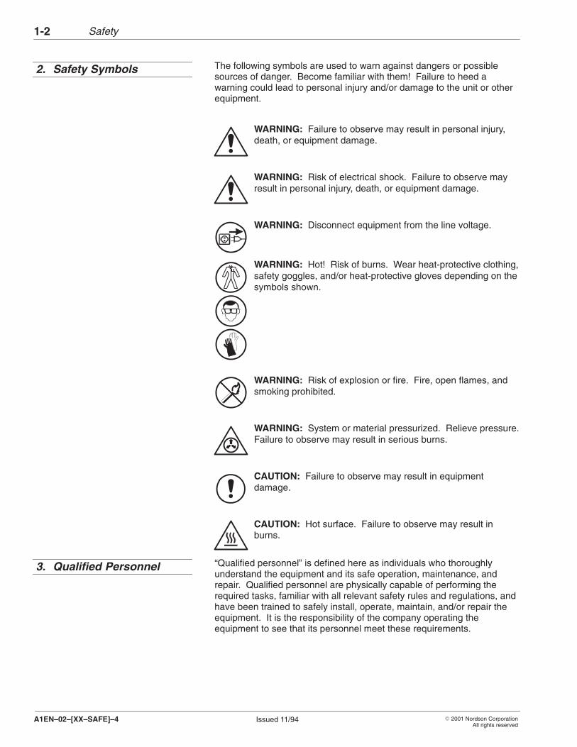
The following symbols are used to warn against dangers or possiblesources of danger. Become familiar with them! Failure to heed awarning could lead to personal injury and/or damage to the unit or otherequipment.
WARNING: Failure to observe may result in personal injury,death, or equipment damage.
WARNING: Risk of electrical shock. Failure to observe mayresult in personal injury, death, or equipment damage.
WARNING: Disconnect equipment from the line voltage.
WARNING: Hot! Risk of burns. Wear heat-protective clothing,safety goggles, and/or heat-protective gloves depending on thesymbols shown.
WARNING: Risk of explosion or fire. Fire, open flames, andsmoking prohibited.
WARNING: System or material pressurized. Relieve pressure.Failure to observe may result in serious burns.
CAUTION: Failure to observe may result in equipmentdamage.
CAUTION: Hot surface. Failure to observe may result inburns.
“Qualified personnel” is defined here as individuals who thoroughlyunderstand the equipment and its safe operation, maintenance, andrepair. Qualified personnel are physically capable of performing therequired tasks, familiar with all relevant safety rules and regulations, andhave been trained to safely install, operate, maintain, and/or repair theequipment. It is the responsibility of the company operating theequipment to see that its personnel meet these requirements.
2. Safety Symbols
3. Qualified Personnel
Safety 1-3
� 2001 Nordson CorporationAll rights reserved
Issued 11/94 A1EN–02–[XX–SAFE]–4
The unit is designed and intended to be used only for the purposedescribed in the Description section. Uses not in accordance with thatsection or as described in this document are considered unintended usesand not in accordance with governing regulations.
WARNING: Use of this equipment in ways other thandescribed in this document may result in personal injury, death,or equipment damage.
The following actions of the owner or operator of the unit are some, butnot all, examples of unintended use which would permit Nordson to claimit is not responsible for personal injury or property damage arising fromsuch unintended use:
� Unapproved modifications or changes to the unit
� Failure to comply with the safety instructions
� Failure to comply with instructions concerning installation, use,operation, maintenance, or repair, or when these tasks are carried outby unqualified personnel
� Use of inappropriate or incompatible foreign materials or auxiliaryequipment
� Failure to observe workplace safety rules or regulations issued bygovernment authorities or safety councils
4. Intended Use
Safety1-4
� 2001 Nordson CorporationAll rights reserved
Issued 11/94A1EN–02–[XX–SAFE]–4
WARNING: Failure to follow the safety procedures can result ininjury or death.
� All electrical, pneumatic, gas, and hydraulic connections andinstallations of hot melt equipment may only be carried out byqualified personnel. Be sure to observe installation instructions forcomponents and accessories.
� Equipment must be properly grounded and fused according to itsrated current consumption (see ID plate).
� Cables which run outside the unit must regularly be checked for wearor damage.
� Power supply wire gauge and insulation must be sufficient to handlerated current consumption.
� Cables must never be squeezed or pinched. Do not locate cables orhoses in high traffic areas.
The unit should be operated by qualified personnel in accordance withthe instructions presented in this document.
WARNING: Failure to follow the safety procedures can result ininjury or death.
� Never allow the unit to be operated by personnel under the influenceof substances which reduce their reaction times, or who are not ableto operate the equipment for physical reasons.
� Prior to each start-up of the unit, check protection and warningdevices and make sure they are fully functional. Do not operate theunit if these devices are not functioning properly.
� When the removal of safety equipment is required for installation,maintenance, or repair of the unit, it must be re-connectedimmediately upon completion of the work.
� Prior to start-up of the unit, check to make sure all safety guards andsafety equipment are in place and functioning properly.
5. Installation and ElectricalConnections
6. Operation

Safety 1-5
� 2001 Nordson CorporationAll rights reserved
Issued 11/94 A1EN–02–[XX–SAFE]–4
� In a humid environment, only equipment featuring a correspondingclass of protection may be operated.
� Do not operate the unit in an explosive environment.
� Keep parts of the body or clothing away from rotating parts. Do notwear loose articles of clothing when operating or servicing units withrotating parts. Take off wrist watches, rings, necklaces, or similarpieces of jewelry and pin up or cover long hair before performing anywork on or with the unit.
� To carry out measurements on work pieces, switch off the unit andwait until it comes to a standstill.
� Never point hand guns or applicator nozzles at yourself or otherpersons.
WARNING: An operator or service technician working with theunit should be aware of less-obvious dangers that often cannotbe completely minimized at production sites:
� Exposed surfaces of the unit which cannot be practicallysafeguarded. They may be hot and take time to cool after the unithas been operating.
� The possibility that electrical potentials may remain in the unit afterthe unit was de-energized
� Hot melt material and vapors
� Hydraulically or pneumatically operated parts of the unit
� Parts winding something up or down which are not covered
If the unit malfunctions, switch it off immediately.
� Turn the circuit breaker or main power switch OFF.
� Have the unit repaired by qualified personnel only.
Less-Obvious Dangers
Action in the Event of UnitMalfunction
Safety1-6
� 2001 Nordson CorporationAll rights reserved
Issued 11/94A1EN–02–[XX–SAFE]–4
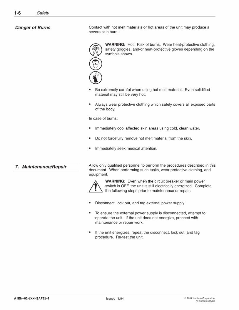
Contact with hot melt materials or hot areas of the unit may produce asevere skin burn.
WARNING: Hot! Risk of burns. Wear heat-protective clothing,safety goggles, and/or heat-protective gloves depending on thesymbols shown.
� Be extremely careful when using hot melt material. Even solidifiedmaterial may still be very hot.
� Always wear protective clothing which safely covers all exposed partsof the body.
In case of burns:
� Immediately cool affected skin areas using cold, clean water.
� Do not forcefully remove hot melt material from the skin.
� Immediately seek medical attention.
Allow only qualified personnel to perform the procedures described in thisdocument. When performing such tasks, wear protective clothing, andequipment.
WARNING: Even when the circuit breaker or main powerswitch is OFF, the unit is still electrically energized. Completethe following steps prior to maintenance or repair:
� Disconnect, lock out, and tag external power supply.
� To ensure the external power supply is disconnected, attempt tooperate the unit. If the unit does not energize, proceed withmaintenance or repair work.
� If the unit energizes, repeat the disconnect, lock out, and tagprocedure. Re-test the unit.
Danger of Burns
7. Maintenance/Repair
Safety 1-7
� 2001 Nordson CorporationAll rights reserved
Issued 11/94 A1EN–02–[XX–SAFE]–4
� Follow the specific instructions provided in this manual to relieve thesystem pressure in the entire unit.
� Secure pneumatically- or hydraulically-operated equipment againstuncontrolled movement.
� Only use parts which do not compromise the safety of the unit. Onlyuse genuine Nordson parts.
� Always use tools with insulated handles when removing or installingcomponents.
NOTE: Always refer to the material manufacturer’s Material Safety DataSheet (MSDS) or material information sheet before working with any ma-terial.
WARNING: Never clean any aluminum part or flush anysystem using halogenated hydrocarbon fluids. Examples ofcommon halogenated hydrocarbons are: dichloromethylene,1,1,1-trichloroethylene, and perchloroethylene. Halogenatedhydrocarbons may react violently with aluminum parts.
WARNING: Fire, open flame, and smoking are prohibited whencleaning fluids are used. Observe all explosion preventionregulations. Cleaning fluids may only be heated usingtemperature-controlled and explosion-protected heaters.
� Never use an open flame to clean the unit or components of the unit.
� Use only cleaning fluids designed or intended to be used with the hotmelt material being used in the unit. Never use paint fluids under anycircumstances.
� Note the flash point of the cleaning fluid used. Only use a controlledheating method to heat fluids.
� Ensure sufficient room ventilation to draw off generated vapors.Avoid prolonged breathing of vapors.
8. Cleaning
Safety1-8
� 2001 Nordson CorporationAll rights reserved
Issued 11/94A1EN–02–[XX–SAFE]–4
NOTE: Always refer to the material manufacturer’s Material Safety DataSheet (MSDS) or material information sheet before working with any hotmelt material.
� Ensure the work area is adequately ventilated.
� Do not exceed recommended processing temperatures. Doing socreates a danger to personnel due to decomposition of the material.
Dispose of equipment and materials used in operation and cleaningaccording to local regulations.
9. Thermoplastic Hot MeltMaterial
10.Equipment and MaterialDisposal
� 2002 Nordson CorporationAll rights reserved
1015471BIssued 10/02
Manual41-3700-MPD-MA-01
Section 2
Description

Description2-0
� 2002 Nordson CorporationAll rights reserved
1015471BIssued 10/02
Manual41-3700-MPD-MA-01
Description 2-1
� 2002 Nordson CorporationAll rights reserved
1015471BIssued 10/02
Manual41-3700-MPD-MA-01
Section 2Description
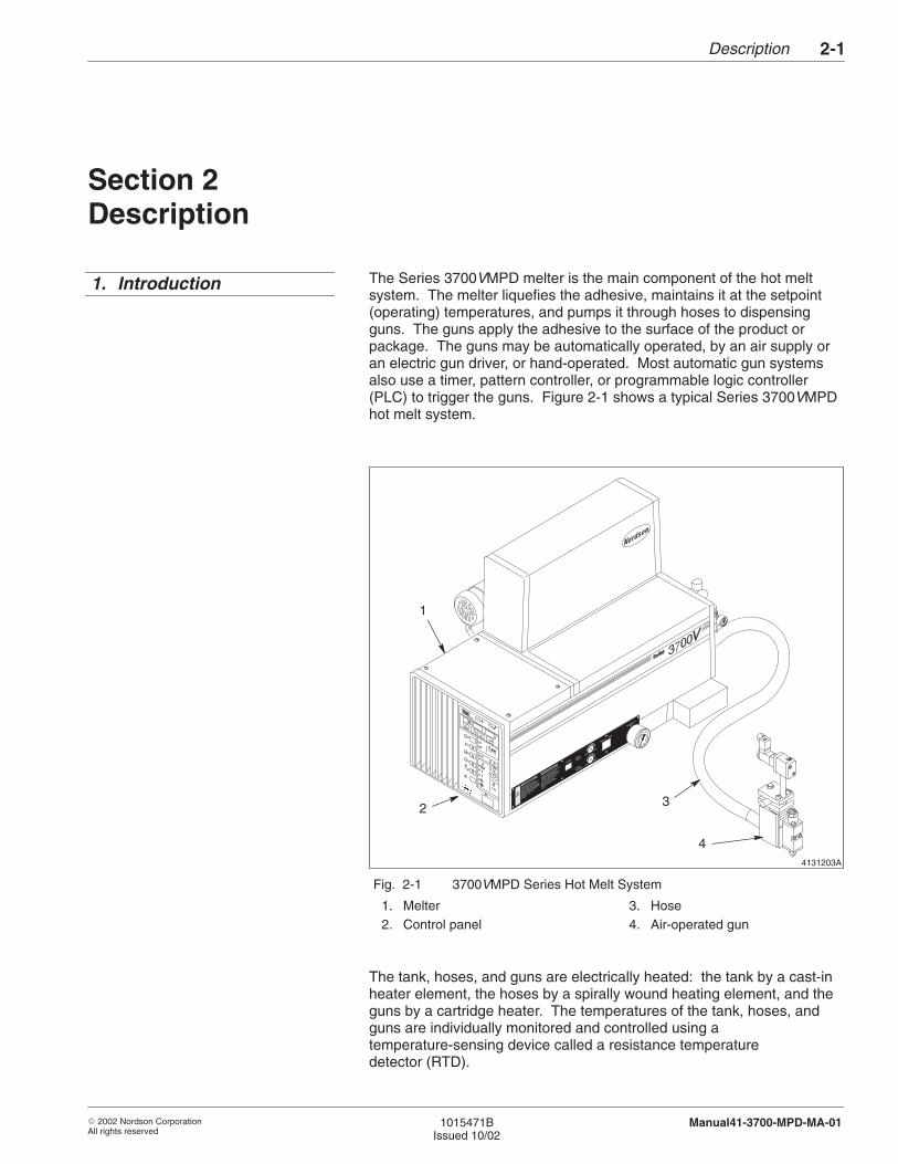
The Series 3700VMPD melter is the main component of the hot meltsystem. The melter liquefies the adhesive, maintains it at the setpoint(operating) temperatures, and pumps it through hoses to dispensingguns. The guns apply the adhesive to the surface of the product orpackage. The guns may be automatically operated, by an air supply oran electric gun driver, or hand-operated. Most automatic gun systemsalso use a timer, pattern controller, or programmable logic controller(PLC) to trigger the guns. Figure 2-1 shows a typical Series 3700VMPDhot melt system.
4131203A
1
3
4
2
Fig. 2-1 3700VMPD Series Hot Melt System
1. Melter2. Control panel
3. Hose4. Air-operated gun
The tank, hoses, and guns are electrically heated: the tank by a cast-inheater element, the hoses by a spirally wound heating element, and theguns by a cartridge heater. The temperatures of the tank, hoses, andguns are individually monitored and controlled using atemperature-sensing device called a resistance temperaturedetector (RTD).
1. Introduction
Description2-2
� 2002 Nordson CorporationAll rights reserved
1015471BIssued 10/02
Manual41-3700-MPD-MA-01
Series 3700VMPD melters can be used to melt and pump almost anythermoplastic adhesive or similar material that can be liquefied andextruded at temperatures below 218 �C (425 �F). The melters are notintended for use with polyurethane-reactive (PUR) adhesives becausethese adhesives require unique systems designed to prevent curing ofthe adhesive inside the dispensing equipment. Series 3700VMPDmelters should be used only as described in this manual.
The melter has three basic modes of operation: startup, operating, andstandby. Each heated component (each hose, each gun, and the tank) isreferred to as a zone.
During a sequential startup, when the clock timer or an operator turns thesystem on the tank and hoses begin to heat. After the temperatures ofthe tank and hoses are all within 19.5 °C (35 °F) of their setpointtemperatures, the guns begin to heat. When the tank, hoses, and gunsare within 3 °C (5 °F) of their setpoint temperatures, a time delay begins.The time delay, which you can adjust, provides additional time for thematerial in the tank to melt. At the end of the time delay, the greenREADY light turns on, indicating that the system is ready for operation.
The capability to heat all zones simultaneously is also available.
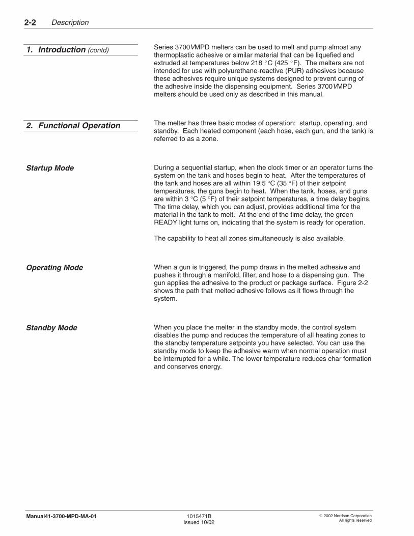
When a gun is triggered, the pump draws in the melted adhesive andpushes it through a manifold, filter, and hose to a dispensing gun. Thegun applies the adhesive to the product or package surface. Figure 2-2shows the path that melted adhesive follows as it flows through thesystem.
When you place the melter in the standby mode, the control systemdisables the pump and reduces the temperature of all heating zones tothe standby temperature setpoints you have selected. You can use thestandby mode to keep the adhesive warm when normal operation mustbe interrupted for a while. The lower temperature reduces char formationand conserves energy.
1. Introduction (contd)
2. Functional Operation
Startup Mode
Operating Mode
Standby Mode
Description 2-3
� 2002 Nordson CorporationAll rights reserved
1015471BIssued 10/02
Manual41-3700-MPD-MA-01
4130777A
1
2
3
4
5
6
7
8
9
10
Fig. 2-2 Adhesive Flow Path of a Typical Gear Pump System
1. Typical motor2. Tank3. Gear pump4. Pressure relief valve
5. Manifold6. Filter7. Gun
8. Hose9. Drain valve
10. Pressure control valve
4131133A
1
2
34
Description2-4
� 2002 Nordson CorporationAll rights reserved
1015471BIssued 10/02
Manual41-3700-MPD-MA-01
The major mechanical components of a Series 3700VMPD melter are thetank, the pump, and the manifold.
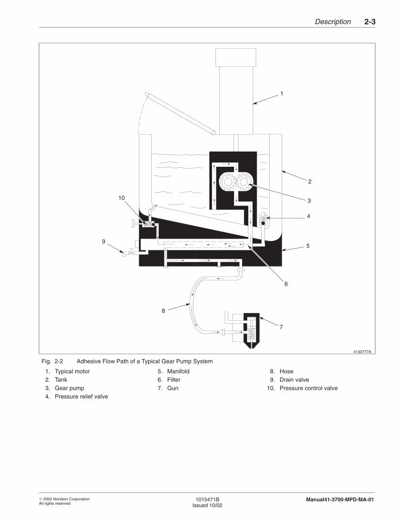
The tank holds a large supply of adhesive and melts it before it ispumped to the hoses and guns. Series 3700 melters have a tank only.The term “tank” is used to mean the tank strainer, and the melting finscollectively including the location of the tank heater connectors. SeeFigure 2-3.
Refer to the Technical Data section for the tank storage capacity andother key information about the tank.
Fig. 2-3 Key Parts of the Tank
1. Tank2. Tank strainer3. Melting fins4. Heater connectors
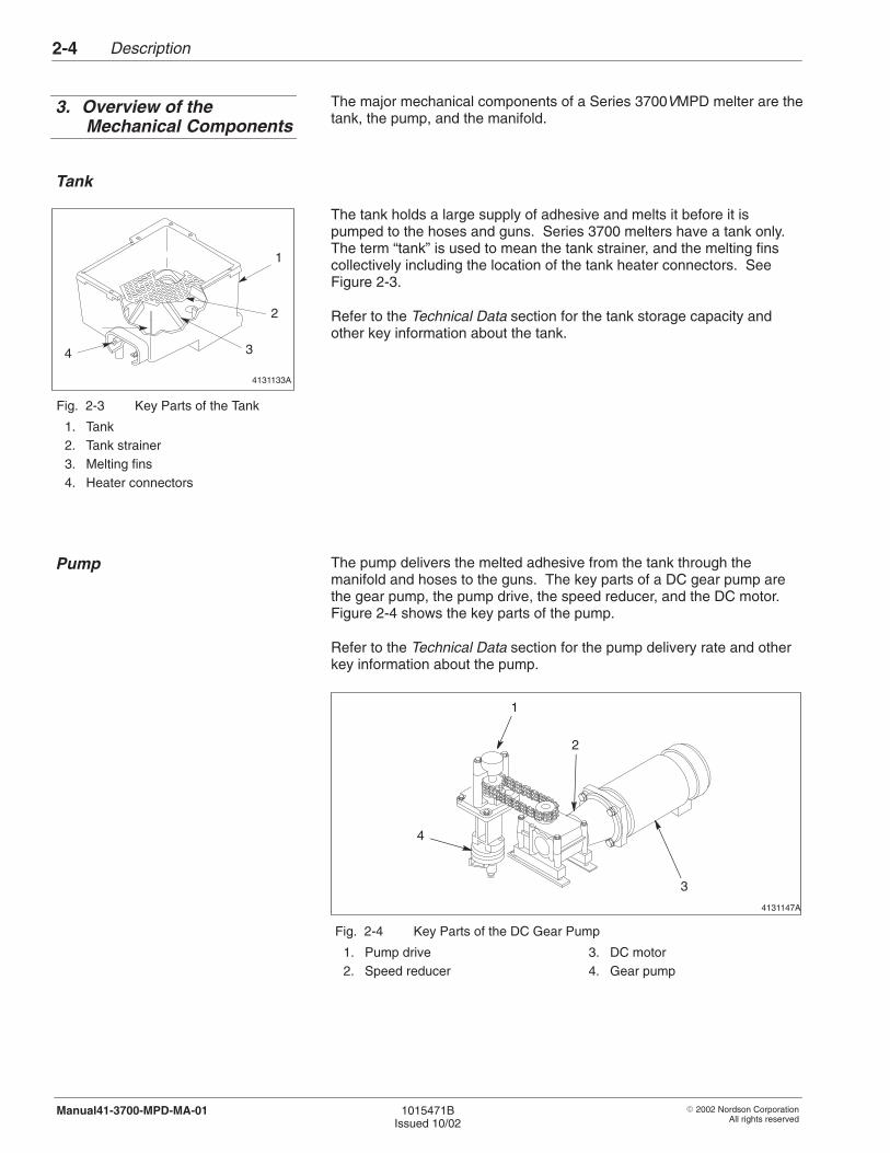
The pump delivers the melted adhesive from the tank through themanifold and hoses to the guns. The key parts of a DC gear pump arethe gear pump, the pump drive, the speed reducer, and the DC motor.Figure 2-4 shows the key parts of the pump.
Refer to the Technical Data section for the pump delivery rate and otherkey information about the pump.
4131147A
3
4
2
1
Fig. 2-4 Key Parts of the DC Gear Pump
1. Pump drive2. Speed reducer
3. DC motor4. Gear pump
3. Overview of theMechanical Components
Tank
Pump
Description 2-5
� 2002 Nordson CorporationAll rights reserved
1015471BIssued 10/02
Manual41-3700-MPD-MA-01
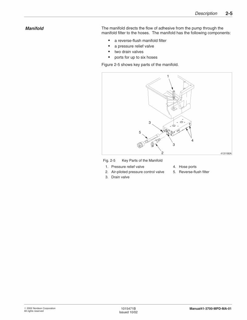
The manifold directs the flow of adhesive from the pump through themanifold filter to the hoses. The manifold has the following components:
� a reverse-flush manifold filter� a pressure relief valve� two drain valves� ports for up to six hoses
Figure 2-5 shows key parts of the manifold.
4131180A
1
43
2
5
3
Fig. 2-5 Key Parts of the Manifold
1. Pressure relief valve2. Air-piloted pressure control valve3. Drain valve
4. Hose ports5. Reverse-flush filter
Manifold
Description2-6
� 2002 Nordson CorporationAll rights reserved
1015471BIssued 10/02
Manual41-3700-MPD-MA-01
The operator panel provides the controls and indicators you need toprogram, operate, and monitor your hot melt system. The key functionsof the operator panel are described in the next part of this section,Control System.
The control system regulates all temperature settings and controls howthe melter functions. The operator panel allows you to program thesystem to meet changing needs:
� Heated zones are controlled individually, giving you more flexibility insetting up your system.
� With the seven-day clock feature, you can tailor operations for a weekat a time, with different schedules for each day of the week.
The control system is designed so that a brownout or power failure willnot cause a loss of your programmed settings.
Operator Panel
4. Control System
Description 2-7
� 2002 Nordson CorporationAll rights reserved
1015471BIssued 10/02
Manual41-3700-MPD-MA-01
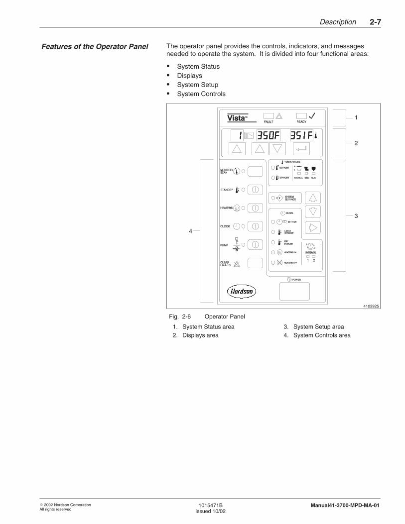
The operator panel provides the controls, indicators, and messagesneeded to operate the system. It is divided into four functional areas:
� System Status� Displays� System Setup� System Controls
4103925
1
2
3
4
Fig. 2-6 Operator Panel
1. System Status area2. Displays area
3. System Setup area4. System Controls area
Features of the Operator Panel
Description2-8
� 2002 Nordson CorporationAll rights reserved
1015471BIssued 10/02
Manual41-3700-MPD-MA-01
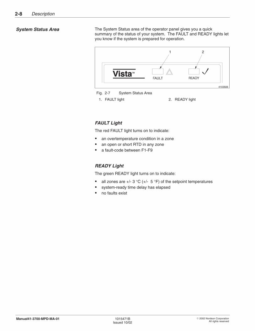
The System Status area of the operator panel gives you a quicksummary of the status of your system. The FAULT and READY lights letyou know if the system is prepared for operation.
4103926
1 2
Fig. 2-7 System Status Area
1. FAULT light 2. READY light
FAULT Light
The red FAULT light turns on to indicate:
� an overtemperature condition in a zone� an open or short RTD in any zone� a fault-code between F1-F9
READY Light
The green READY light turns on to indicate:
� all zones are +/- 3 °C (+/- 5 °F) of the setpoint temperatures� system-ready time delay has elapsed� no faults exist
System Status Area
Description 2-9
� 2002 Nordson CorporationAll rights reserved
1015471BIssued 10/02
Manual41-3700-MPD-MA-01
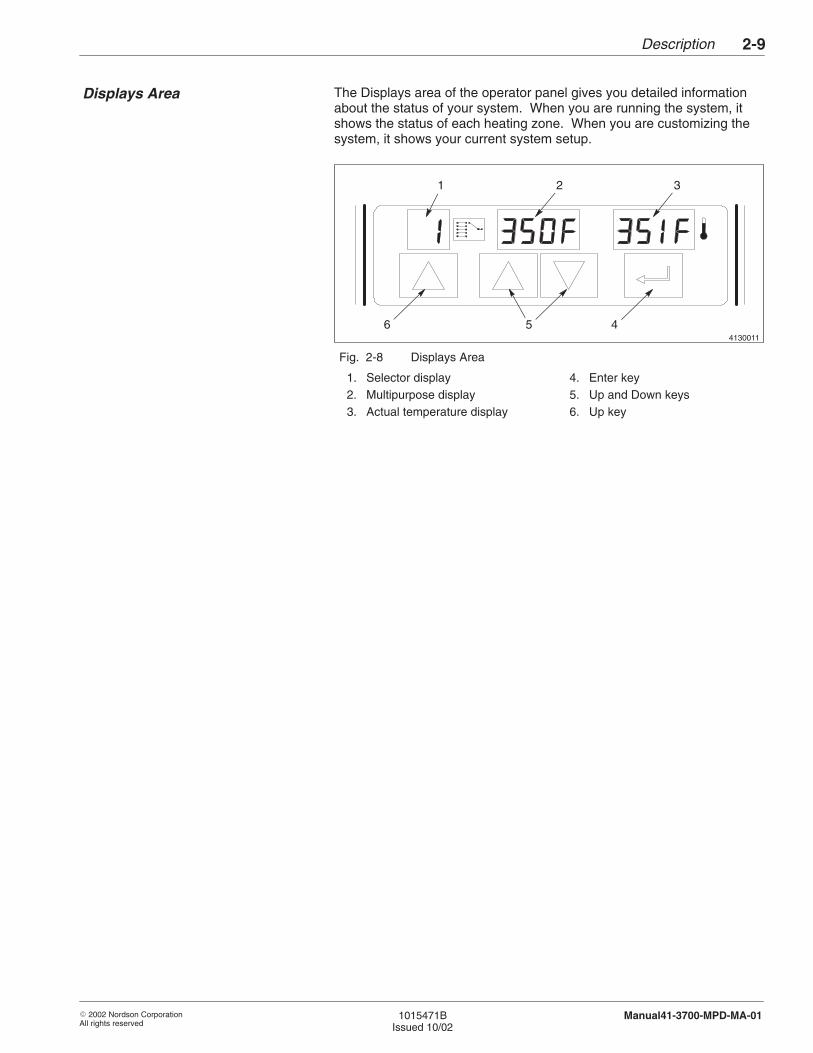
The Displays area of the operator panel gives you detailed informationabout the status of your system. When you are running the system, itshows the status of each heating zone. When you are customizing thesystem, it shows your current system setup.
4130011
1 2 3
46 5
Fig. 2-8 Displays Area
1. Selector display2. Multipurpose display3. Actual temperature display
4. Enter key5. Up and Down keys6. Up key
Displays Area
Description2-10
� 2002 Nordson CorporationAll rights reserved
1015471BIssued 10/02
Manual41-3700-MPD-MA-01
Selector Display and Up Key
The Selector display allows you to access information about the status ofyour system during operation and system setup. The display shows the
� selected zone number when used with TEMPERATURE and whenscanning
� day when used with CLOCK
� feature number when used with SYSTEM SETTINGS
The Up key, which is located below the Selector display, changes thevalue of a setting.
Multipurpose Display and Keys
During normal operation, the Multipurpose display shows the setpointtemperature for a selected zone. This allows you to compare the actualtemperature of the displayed zone with its targeted temperature.
Actual Temperature Display
The Actual Temperature display shows the actual temperature of theheated zone. When the scan mode is enabled, each zone is displayed insequence. When the scan mode is disabled, only the temperature for theselected zone is displayed.
Enter Key
The Enter key saves the number shown in the Multipurpose display.

4103928
3
1
4
5
2
Description 2-11
� 2002 Nordson CorporationAll rights reserved
1015471BIssued 10/02
Manual41-3700-MPD-MA-01
The System Setup area of the operator panel allows you to customize thesystem to your needs. From this area you can control
� the temperature at which each zone operates (TEMPERATURE)� how the melter operates (SYSTEM SETTINGS)� when the system operates (CLOCK)
To customize system controls, use the keys in the System Setup area inconjunction with the keys in the Displays area.
Up and Down Keys
The Up and Down keys select features within the System Setup area,allowing you to tailor the system to your needs. You can select thefollowing features using the Up and Down keys:
� SETPOINT temperature� STANDBY temperature� SYSTEM SETTINGS� SET TIME� ENTER STANDBY� EXIT STANDBY� HEATERS ON� HEATERS OFF
Fig. 2-9 System Setup Area
1. Up and Down keys2. Right key3. TEMPERATURE area4. SYSTEM SETTINGS area5. CLOCK area
Right Key
The Right key selects features within the System Setup area, allowingyou to tailor the system to your needs. You can select the followingfeatures using the Right key:
� INTERNAL zone� HOSE zone� GUN zone� INTERVAL 1� INTERVAL 2
System Setup Area
Description2-12
� 2002 Nordson CorporationAll rights reserved
1015471BIssued 10/02
Manual41-3700-MPD-MA-01
TEMPERATURE Area
The TEMPERATURE area of System Setup allows you to program thesetpoint and standby temperatures for three types of heated zones:internal, hose, or gun.
When used in the TEMPERATURE area,
� The Up and Down keys select SETPOINT or STANDBY.
� The Right key selects the zone type (internal, hose, or gun) forprogramming temperatures (standby or setpoint).
SYSTEM SETTINGS Area
From the SYSTEM SETTINGS area, you can customize or check thesettings of the following system features:
� password enable� system-ready time delay� overtemperature setpoint� Celsius or Fahrenheit units� global temperature bands� individual temperature bands� sequential startup or simultaneous startup� display heater proportioning� warning or power notification� ready or pump notification� auto-energize heaters� time with heaters on� fault log display
4103929
1
2
3
4
5
6 7
Description 2-13
� 2002 Nordson CorporationAll rights reserved
1015471BIssued 10/02
Manual41-3700-MPD-MA-01
CLOCK Area
From the CLOCK area you can program the system to turn heaters on oroff or to place the system in standby or operating mode at a time that youselect. The clock stores two sets of times, referred to as intervals. Eachinterval stores four settings as shown in Table 2-1.
Table 2-1 Interval Settings
INTERVAL 1 INTERVAL 2
Standby Settings Enter
Exit
Enter
Exit
Heater Settings On
Off
On
Off
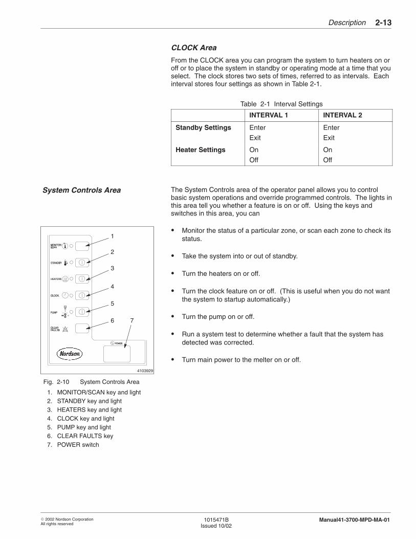
The System Controls area of the operator panel allows you to controlbasic system operations and override programmed controls. The lights inthis area tell you whether a feature is on or off. Using the keys andswitches in this area, you can
� Monitor the status of a particular zone, or scan each zone to check itsstatus.
� Take the system into or out of standby.
� Turn the heaters on or off.
� Turn the clock feature on or off. (This is useful when you do not wantthe system to startup automatically.)
� Turn the pump on or off.
� Run a system test to determine whether a fault that the system hasdetected was corrected.
� Turn main power to the melter on or off.
Fig. 2-10 System Controls Area
1. MONITOR/SCAN key and light2. STANDBY key and light3. HEATERS key and light4. CLOCK key and light5. PUMP key and light6. CLEAR FAULTS key7. POWER switch
System Controls Area

Description2-14
� 2002 Nordson CorporationAll rights reserved
1015471BIssued 10/02
Manual41-3700-MPD-MA-01
MONITOR/SCAN Key and Light
Pressing the MONITOR/SCAN key places the system in the monitor orscan mode. In the scan mode,
� The system scans each heated zone, displaying each zone’stemperature in sequence.
� If the system-ready time delay feature is active, the system shows thenumber of minutes remaining until the system is ready for operation.
� The MONITOR/SCAN light turns on and stays on.
In the monitor mode,
� The system displays the temperature of only the zone currentlyselected.
� If the system-ready time delay feature is active and is currentlyselected for monitoring, the system shows the number of minutesremaining until the system is ready for operation.
� The MONITOR/SCAN light stays on.
Description 2-15
� 2002 Nordson CorporationAll rights reserved
1015471BIssued 10/02
Manual41-3700-MPD-MA-01
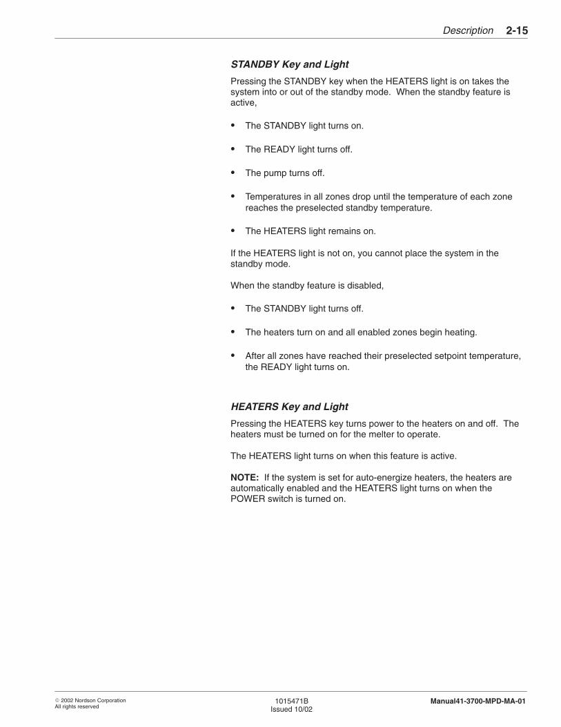
STANDBY Key and Light
Pressing the STANDBY key when the HEATERS light is on takes thesystem into or out of the standby mode. When the standby feature isactive,
� The STANDBY light turns on.
� The READY light turns off.
� The pump turns off.
� Temperatures in all zones drop until the temperature of each zonereaches the preselected standby temperature.
� The HEATERS light remains on.
If the HEATERS light is not on, you cannot place the system in thestandby mode.
When the standby feature is disabled,
� The STANDBY light turns off.
� The heaters turn on and all enabled zones begin heating.
� After all zones have reached their preselected setpoint temperature,the READY light turns on.
HEATERS Key and Light
Pressing the HEATERS key turns power to the heaters on and off. Theheaters must be turned on for the melter to operate.
The HEATERS light turns on when this feature is active.
NOTE: If the system is set for auto-energize heaters, the heaters areautomatically enabled and the HEATERS light turns on when thePOWER switch is turned on.
Description2-16
� 2002 Nordson CorporationAll rights reserved
1015471BIssued 10/02
Manual41-3700-MPD-MA-01
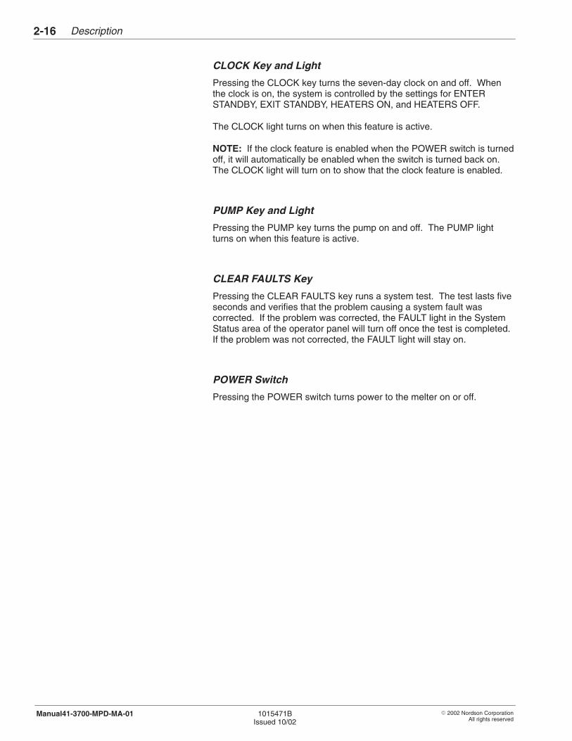
CLOCK Key and Light
Pressing the CLOCK key turns the seven-day clock on and off. Whenthe clock is on, the system is controlled by the settings for ENTERSTANDBY, EXIT STANDBY, HEATERS ON, and HEATERS OFF.
The CLOCK light turns on when this feature is active.
NOTE: If the clock feature is enabled when the POWER switch is turnedoff, it will automatically be enabled when the switch is turned back on.The CLOCK light will turn on to show that the clock feature is enabled.
PUMP Key and Light
Pressing the PUMP key turns the pump on and off. The PUMP lightturns on when this feature is active.
CLEAR FAULTS Key
Pressing the CLEAR FAULTS key runs a system test. The test lasts fiveseconds and verifies that the problem causing a system fault wascorrected. If the problem was corrected, the FAULT light in the SystemStatus area of the operator panel will turn off once the test is completed.If the problem was not corrected, the FAULT light will stay on.
POWER Switch
Pressing the POWER switch turns power to the melter on or off.

� 2002 Nordson CorporationAll rights reserved
1015471BIssued 10/02
Manual41-3700VMPD-MA-01
Section 3
Installation

Installation3-0
� 2002 Nordson CorporationAll rights reserved
1015471BIssued 10/02
Manual41-3700VMPD-MA-01
Installation 3-1
� 2002 Nordson CorporationAll rights reserved
1015471BIssued 10/02
Manual41-3700VMPD-MA-01
Section 3Installation
WARNING: Allow only qualified personnel to perform thefollowing tasks. Follow the safety instructions in this documentand all other related documentation.
This section of the manual describes how to install the melter, hoses, andguns, and how to set up and customize the melter for your operation.
Exercise normal care to prevent equipment damage during unpacking.After unpacking the equipment, inspect it for any damage that may haveoccurred during shipping. Look for dents and scratches and make sureall fasteners are tight. Report any damage to your Nordsonrepresentative.
The following general guidelines are provided to help you obtain the bestperformance from your melter. Additional guidelines are providedthroughout this section as appropriate.
Carefully select the installation location for the melter, hoses, and guns.
� Make sure the mounting surface is level and can support the weightof a full melter. For the weight of a full melter, refer to the TechnicalData section.
� Allow enough room to open the tank lid, open the electrical enclosure,remove the filter assembly, lift off the pump cover, make the electricalconnections, and drain the manifold filter. For melter dimensions andrecommended clearances, refer to the Technical Data section.
1. Introduction
2. Inspection
3. Installation Guidelines
Installation Location
Installation3-2
� 2002 Nordson CorporationAll rights reserved
1015471BIssued 10/02
Manual41-3700VMPD-MA-01
� Position the melter so the drain valve projects over the edge of themounting surface.
� Allow enough room for installers to route the hoses properly.
� Make sure an operator can reach all controls.
� Allow enough clearance for maintenance personnel to service andrepair the melter.
Observe the following wiring requirements when choosing a location foryour melter.
� Allow enough room to route your electrical wiring to the melter. Youcan use the access holes in the base of the melter for either rearaccess or bottom access.
� Make connections with the minimum length of wire needed. A longwire can act as an antenna for electrical noise.
The power requirements of your hoses and guns must be determined tomake sure that you do not overload the melter. If your Nordsonrepresentative has not already checked to see that your melter cansupport all of the hoses and guns you plan to install, you need tocalculate your hose/gun power requirements now. You also need tocheck your calculations if you change your system configuration or addnew hoses or guns.
To determine your hose/gun power requirements, refer to the procedurefor calculating hose/gun capacity in the Technical Data section. If youneed help, contact your Nordson representative.
Installation Location (contd)
Wiring Requirements
Hose/Gun Power Requirements
Installation 3-3
� 2002 Nordson CorporationAll rights reserved
1015471BIssued 10/02
Manual41-3700VMPD-MA-01
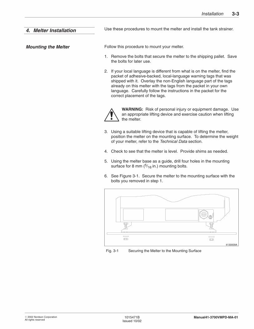
Use these procedures to mount the melter and install the tank strainer.
Follow this procedure to mount your melter.
1. Remove the bolts that secure the melter to the shipping pallet. Savethe bolts for later use.
2. If your local language is different from what is on the melter, find thepacket of adhesive-backed, local-language warning tags that wasshipped with it. Overlay the non-English language part of the tagsalready on this melter with the tags from the packet in your ownlanguage. Carefully follow the instructions in the packet for thecorrect placement of the tags.
WARNING: Risk of personal injury or equipment damage. Usean appropriate lifting device and exercise caution when liftingthe melter.
3. Using a suitable lifting device that is capable of lifting the melter,position the melter on the mounting surface. To determine the weightof your melter, refer to the Technical Data section.
4. Check to see that the melter is level. Provide shims as needed.
5. Using the melter base as a guide, drill four holes in the mountingsurface for 8 mm (5/16 in.) mounting bolts.
6. See Figure 3-1. Secure the melter to the mounting surface with thebolts you removed in step 1.
4130009A
Fig. 3-1 Securing the Melter to the Mounting Surface
4. Melter Installation
Mounting the Melter
Installation3-4
� 2002 Nordson CorporationAll rights reserved
1015471BIssued 10/02
Manual41-3700VMPD-MA-01
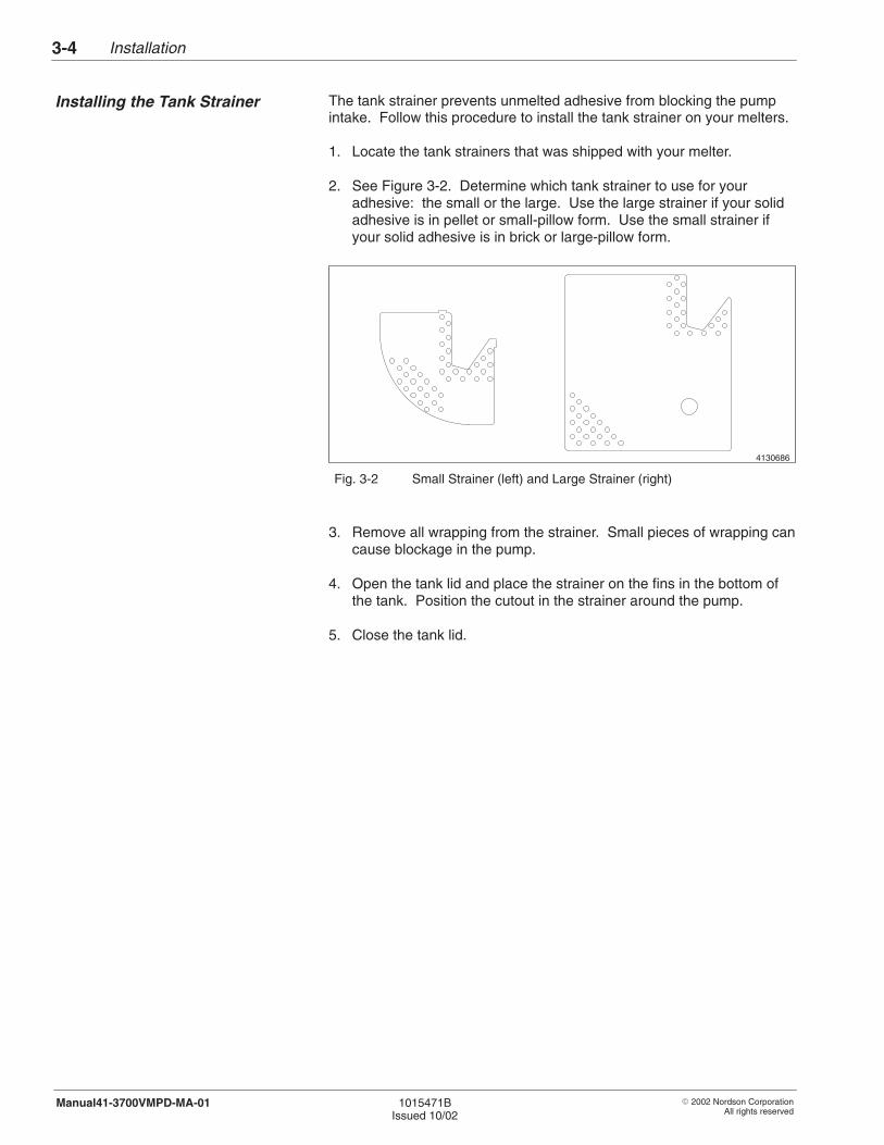
The tank strainer prevents unmelted adhesive from blocking the pumpintake. Follow this procedure to install the tank strainer on your melters.
1. Locate the tank strainers that was shipped with your melter.
2. See Figure 3-2. Determine which tank strainer to use for youradhesive: the small or the large. Use the large strainer if your solidadhesive is in pellet or small-pillow form. Use the small strainer ifyour solid adhesive is in brick or large-pillow form.
4130686
Fig. 3-2 Small Strainer (left) and Large Strainer (right)
3. Remove all wrapping from the strainer. Small pieces of wrapping cancause blockage in the pump.
4. Open the tank lid and place the strainer on the fins in the bottom ofthe tank. Position the cutout in the strainer around the pump.
5. Close the tank lid.
Installing the Tank Strainer
Installation 3-5
� 2002 Nordson CorporationAll rights reserved
1015471BIssued 10/02
Manual41-3700VMPD-MA-01
Follow these procedures to install hoses and guns. Before proceeding,complete the procedures in Melter Installation.
Install guns by following the instructions in the gun manual.
CAUTION: Make sure that you do not exceed the maximumpower capabilities of your melter. Refer to the procedure forcalculating hose/gun capacity in the Technical Data section.
1. Connect hoses and hose cordsets to the guns.
2. Route the hoses from the guns to the melter. Make sure the hosesdo not contact sharp objects or abrasive surfaces. Follow thehose-routing guidelines illustrated on the hose packaging materials.
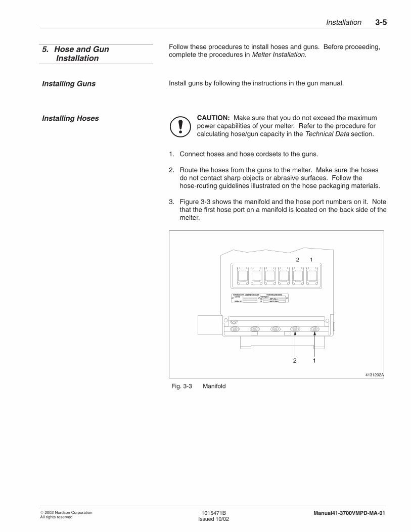
3. Figure 3-3 shows the manifold and the hose port numbers on it. Notethat the first hose port on a manifold is located on the back side of themelter.
4131202A
2 1
2 1
Fig. 3-3 Manifold
5. Hose and GunInstallation
Installing Guns
Installing Hoses
Installation3-6
� 2002 Nordson CorporationAll rights reserved
1015471BIssued 10/02
Manual41-3700VMPD-MA-01
CAUTION: Failure to connect the first hose as instructedcreates a dead area where char can build up.
4. Refer to Table 3-1 to decide where to install the first hose.
Table 3-1 Order for Connecting Hoses
Type of Manifold Instructions
Six-port manifold Use hose port 1 or 2. If you planto install six hoses (either now orin the future), use hose port 1 forthe first hose (see Note A). If youplan to install fewer than sixhoses, you can use hose port 2for the first hose.
NOTE A: To install six hoses, your melter must have the ability to heatsix hoses. Check to see if your melter has six hoseelectrical receptacles. Melters can be ordered with two, four,or six receptacles.
WARNING: Risk of burns. Hose ports that are unused must beclosed with a plug.
5. Remove the O-ring plug from the hose port where you plan to installthe first hose. Keep the O-ring plug for later use during maintenanceand servicing procedures.
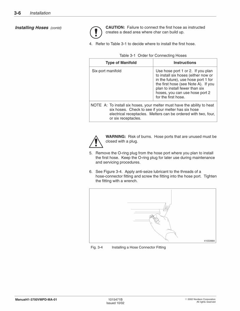
6. See Figure 3-4. Apply anti-seize lubricant to the threads of ahose-connector fitting and screw the fitting into the hose port. Tightenthe fitting with a wrench.
4103398A
Fig. 3-4 Installing a Hose Connector Fitting
Installing Hoses (contd)
Installation 3-7
� 2002 Nordson CorporationAll rights reserved
1015471BIssued 10/02
Manual41-3700VMPD-MA-01
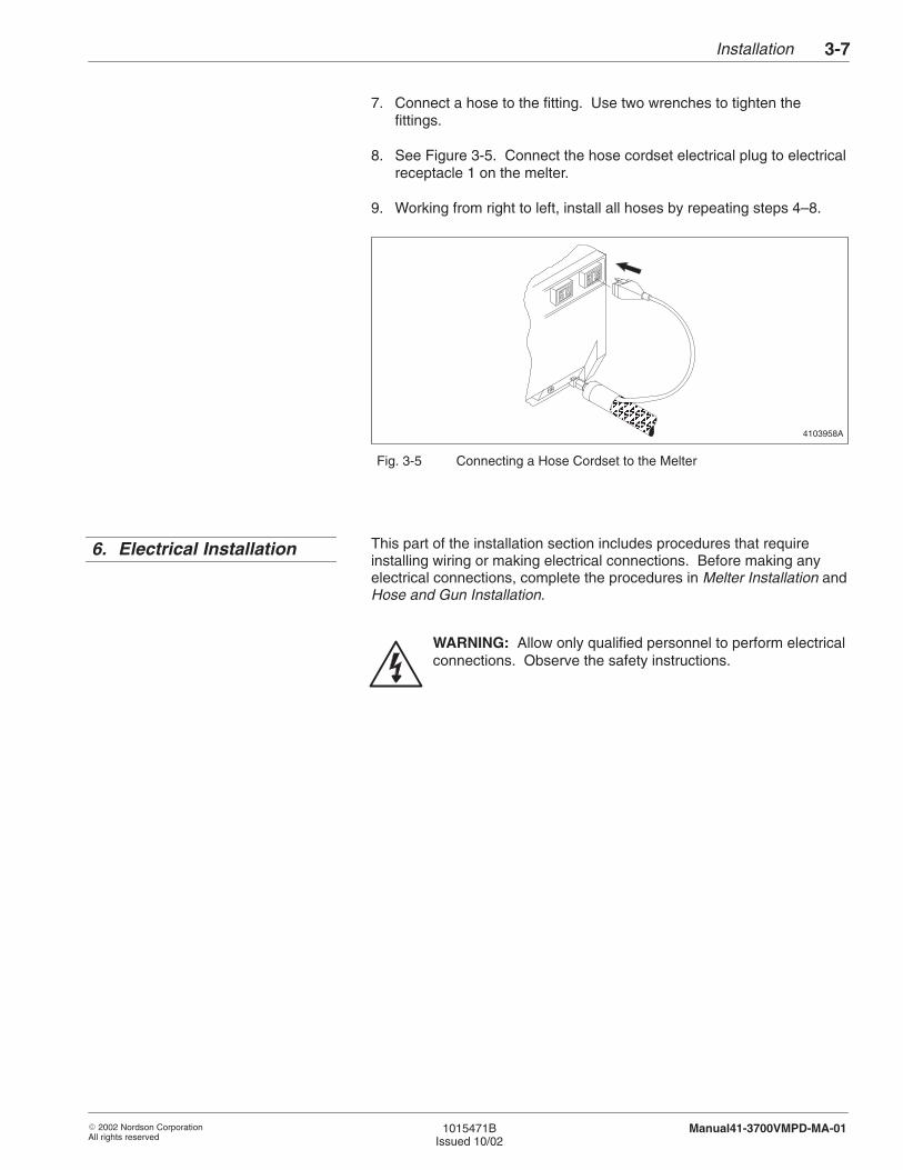
7. Connect a hose to the fitting. Use two wrenches to tighten thefittings.
8. See Figure 3-5. Connect the hose cordset electrical plug to electricalreceptacle 1 on the melter.
9. Working from right to left, install all hoses by repeating steps 4–8.
4103958AÂÂ
ÂÂÂÂÂÂÂÂÂ
ÂÂÂÂÂ
Â
Â
Fig. 3-5 Connecting a Hose Cordset to the Melter
This part of the installation section includes procedures that requireinstalling wiring or making electrical connections. Before making anyelectrical connections, complete the procedures in Melter Installation andHose and Gun Installation.
WARNING: Allow only qualified personnel to perform electricalconnections. Observe the safety instructions.
6. Electrical Installation
Installation3-8
� 2002 Nordson CorporationAll rights reserved
1015471BIssued 10/02
Manual41-3700VMPD-MA-01
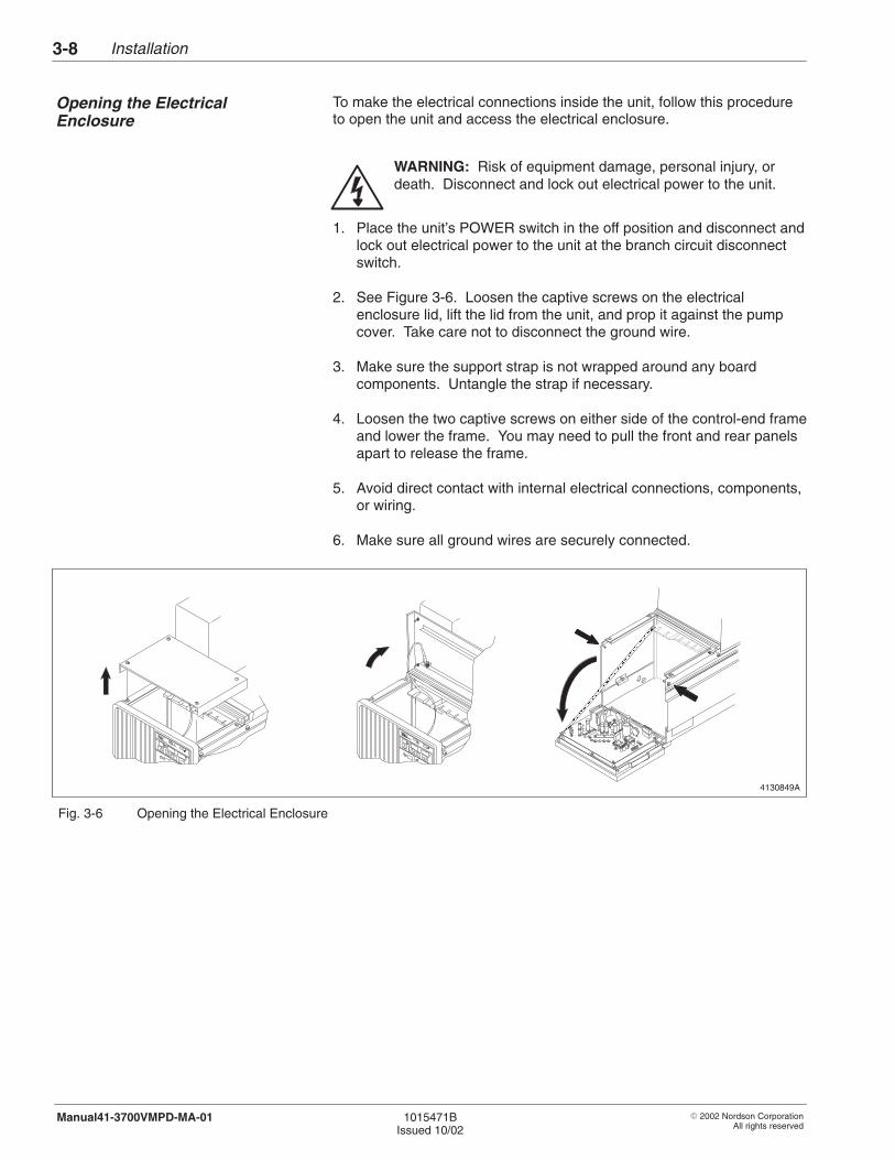
To make the electrical connections inside the unit, follow this procedureto open the unit and access the electrical enclosure.
WARNING: Risk of equipment damage, personal injury, ordeath. Disconnect and lock out electrical power to the unit.
1. Place the unit’s POWER switch in the off position and disconnect andlock out electrical power to the unit at the branch circuit disconnectswitch.
2. See Figure 3-6. Loosen the captive screws on the electricalenclosure lid, lift the lid from the unit, and prop it against the pumpcover. Take care not to disconnect the ground wire.
3. Make sure the support strap is not wrapped around any boardcomponents. Untangle the strap if necessary.
4. Loosen the two captive screws on either side of the control-end frameand lower the frame. You may need to pull the front and rear panelsapart to release the frame.
5. Avoid direct contact with internal electrical connections, components,or wiring.
6. Make sure all ground wires are securely connected.
4130849A
ÏÏÏÏÏÏÏÏÏÏÏÏÏÏÏÏÏÏÏÏÏÏÏÏÏÏÏÏÏÏ
Fig. 3-6 Opening the Electrical Enclosure
Opening the ElectricalEnclosure
Installation 3-9
� 2002 Nordson CorporationAll rights reserved
1015471BIssued 10/02
Manual41-3700VMPD-MA-01
The input/output (I/O) board for Series 3000V hot melt melters allows youto connect devices to the melter to remotely monitor and control keymelter features. Your melter is equipped with the standard I/O board.
The standard I/O board inputs allow you to
� remotely turn the standby feature on� remotely start the pump� have the melter automatically enter the standby mode if guns are
not fired for a specified period of time
The standard I/O board outputs allow you to remotely monitor
� power on/off status� pump on/off status� standby on/off status� warning conditions
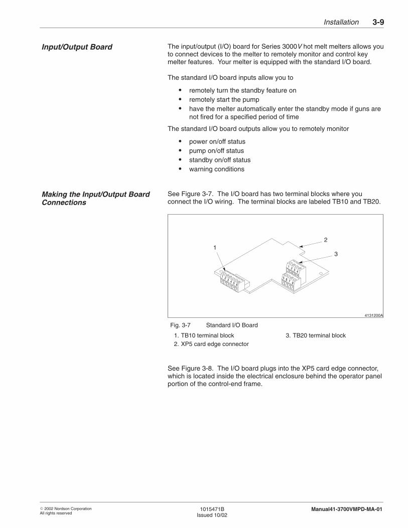
See Figure 3-7. The I/O board has two terminal blocks where youconnect the I/O wiring. The terminal blocks are labeled TB10 and TB20.
4131200A
12
3
Fig. 3-7 Standard I/O Board
1. TB10 terminal block2. XP5 card edge connector
3. TB20 terminal block
See Figure 3-8. The I/O board plugs into the XP5 card edge connector,which is located inside the electrical enclosure behind the operator panelportion of the control-end frame.
Input/Output Board
Making the Input/Output BoardConnections

Installation3-10
� 2002 Nordson CorporationAll rights reserved
1015471BIssued 10/02
Manual41-3700VMPD-MA-01
4130282
1
2 3
1
Fig. 3-8 XP5 Card Edge Connector
1. Control-end frame2. Flange
3. XP5 card edge connector
You will need only to install ferrites and connect the I/O wiring. A ferrite isa device used to reduce electrical noise.
WARNING: Risk of equipment damage, personal injury, ordeath. Disconnect and lock out electrical power to the melter,including input/output (I/O) lines.
1. Turn off the melter; then disconnect electrical service to it.
2. Open the electrical enclosure. Refer to Opening and Closing theElectrical Enclosure in the Control section.
3. If you have not already done so, carefully remove a plug from one ofthe smaller knockout holes on either the back side or the bottom ofthe melter (whichever is most convenient for your operation) andinstall a strain relief to support and protect the I/O wiring. Avoidcontact with any printed circuit boards.
WARNING: Risk of equipment damage, personal injury, ordeath. For a proper and safe installation, make sure you meetthe requirements in the following step.
Making the Input/Output BoardConnections (contd)
Installation 3-11
� 2002 Nordson CorporationAll rights reserved
1015471BIssued 10/02
Manual41-3700VMPD-MA-01
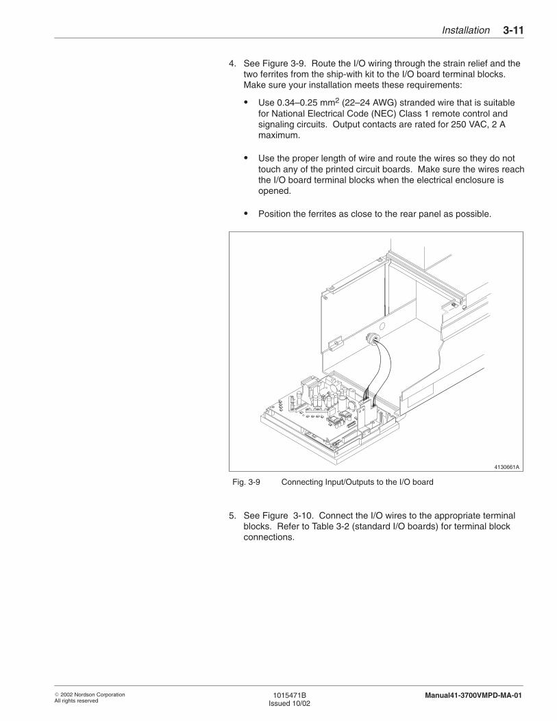
4. See Figure 3-9. Route the I/O wiring through the strain relief and thetwo ferrites from the ship-with kit to the I/O board terminal blocks.Make sure your installation meets these requirements:
� Use 0.34–0.25 mm2 (22–24 AWG) stranded wire that is suitablefor National Electrical Code (NEC) Class 1 remote control andsignaling circuits. Output contacts are rated for 250 VAC, 2 Amaximum.
� Use the proper length of wire and route the wires so they do nottouch any of the printed circuit boards. Make sure the wires reachthe I/O board terminal blocks when the electrical enclosure isopened.
� Position the ferrites as close to the rear panel as possible.
4130661A
Fig. 3-9 Connecting Input/Outputs to the I/O board
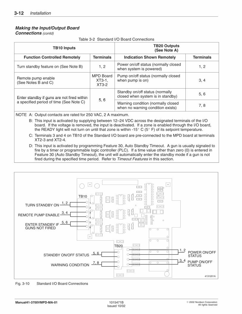
5. See Figure 3-10. Connect the I/O wires to the appropriate terminalblocks. Refer to Table 3-2 (standard I/O boards) for terminal blockconnections.
Installation3-12
� 2002 Nordson CorporationAll rights reserved
1015471BIssued 10/02
Manual41-3700VMPD-MA-01
Table 3-2 Standard I/O Board Connections
TB10 Inputs TB20 Outputs(See Note A)
Function Controlled Remotely Terminals Indication Shown Remotely Terminals
Turn standby feature on (See Note B) 1, 2 Power on/off status (normally closedwhen system is powered)
1, 2
Remote pump enable (See Notes B and C)
MPD BoardXT3-1,XT3-2
Pump on/off status (normally closedwhen pump is on) 3, 4
Enter standby if guns are not fired within5 6
Standby on/off status (normallyclosed when system is in standby)
5, 6Enter standby if guns are not fired withina specified period of time (See Note C) 5, 6
Warning condition (normally closedwhen no warning condition exists)
7, 8
NOTE A: Output contacts are rated for 250 VAC, 2 A maximum.
B: This input is activated by supplying between 12–24 VDC across the designated terminals of the I/Oboard. If the voltage is removed, the input is deactivated. If a zone is enabled through the I/O board,the READY light will not turn on until that zone is within -15� C (5� F) of its setpoint temperature.
C: Terminals 3 and 4 on TB10 of the Standard I/O board are pre-connected to the MPD board at terminalsXT2-3 and XT2-4.
D: This input is activated by programming Feature 30, Auto Standby Timeout. A gun is usually signaled tofire by a timer or programmable logic controller (PLC). If a time value other than zero (0) is entered inFeature 30 (Auto Standby Timeout), the unit will automatically enter the standby mode if a gun is notfired during the specified time period. Refer to Timeout Features in this section.
4131201A
TURN STANDBY ON
REMOTE PUMP ENABLE
ENTER STANDBY IF
STANDBY ON/OFF STATUS 5, 6
WARNING CONDITION7, 8
TB10
TB20
POWER ON/OFFSTATUS
PUMP ON/OFFSTATUS
GUNS NOT FIRED
1
2
3
4
5
6
1, 2
3, 4
5, 6
1, 2
3, 4
Fig. 3-10 Standard I/O Board Connections
Making the Input/Output BoardConnections (contd)

Installation 3-13
� 2002 Nordson CorporationAll rights reserved
1015471BIssued 10/02
Manual41-3700VMPD-MA-01
6. Close and secure the electrical enclosure. Refer to Opening andClosing the Electrical Enclosure in the Control section.
7. Restore power to the melter and resume normal operation.
Follow this procedure to connect the standard output contacts that areprovided on all units. If you do not wish to connect any outputs, skip tothe next procedure, Connecting Electrical Service.
Output contacts allow you to automatically activate other equipment or toactivate devices for remote monitoring of the unit’s operations. Table 3-3describes the standard output contacts. If your unit has an optionalinput/output (I/O) board, there are additional outputs and several inputsyou can connect. Refer to Making the Input/Output Board Connections.
Table 3-3 Standard Output Contacts
Output Contact Function
System Warning Used to signal a device that will alert remotelylocated operators of a warning condition
System Fault Used to signal a device that will alert remotelylocated operators of a system fault condition. Thisoutput is typically used to turn on a light or to soundan alarm.
System Ready Used to signal a device that will alert remotelylocated operators that the system is ready foroperation (up to temperature) or that the unit’spump is on. This output is typically used to send aready signal to a production line so that the lineturns on only when the unit is ready to pumpadhesive.
8. If you have not already done so, open the electrical enclosure. Referto Opening the Electrical Enclosure in this section.
9. If you have not already done so, carefully remove a knockout holeplug from one of the larger holes on either the back side or the bottomof the unit (whichever is most convenient for your operation). Avoidcontact with any printed circuit boards.
Connecting Output Contacts(Optional)
Installation3-14
� 2002 Nordson CorporationAll rights reserved
1015471BIssued 10/02
Manual41-3700VMPD-MA-01
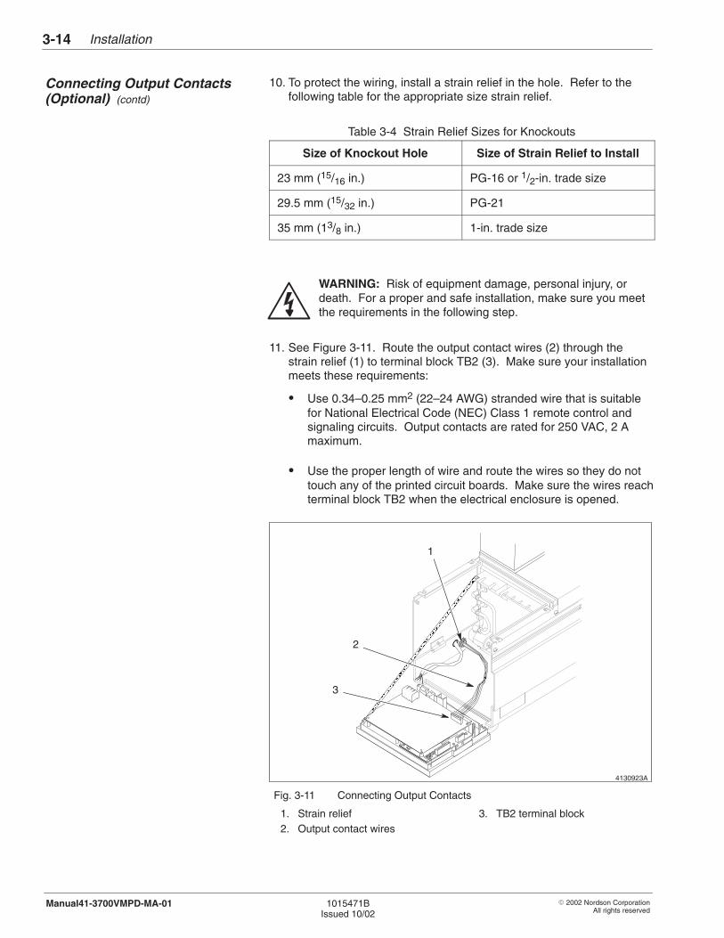
10. To protect the wiring, install a strain relief in the hole. Refer to thefollowing table for the appropriate size strain relief.
Table 3-4 Strain Relief Sizes for Knockouts
Size of Knockout Hole Size of Strain Relief to Install
23 mm (15/16 in.) PG-16 or 1/2-in. trade size
29.5 mm (15/32 in.) PG-21
35 mm (13/8 in.) 1-in. trade size
WARNING: Risk of equipment damage, personal injury, ordeath. For a proper and safe installation, make sure you meetthe requirements in the following step.
11. See Figure 3-11. Route the output contact wires (2) through thestrain relief (1) to terminal block TB2 (3). Make sure your installationmeets these requirements:
� Use 0.34–0.25 mm2 (22–24 AWG) stranded wire that is suitablefor National Electrical Code (NEC) Class 1 remote control andsignaling circuits. Output contacts are rated for 250 VAC, 2 Amaximum.
� Use the proper length of wire and route the wires so they do nottouch any of the printed circuit boards. Make sure the wires reachterminal block TB2 when the electrical enclosure is opened.
4130923A
ÏÏÏÏÏÏÏÏÏÏÏÏÏÏÏÏÏÏÏÏÏÏÏÏÏÏÏÏÏÏÏÏÏÏÏÏÏÏÏÏÏÏÏÏÏÏÏÏÏÏÏÏÏÏÏÏÏÏÏÏÏÏÏ
1
2
3
Fig. 3-11 Connecting Output Contacts
1. Strain relief2. Output contact wires
3. TB2 terminal block
Connecting Output Contacts(Optional) (contd)
Installation 3-15
� 2002 Nordson CorporationAll rights reserved
1015471BIssued 10/02
Manual41-3700VMPD-MA-01
12. Connect the output wires to the plug for terminal block TB2 from theship-with kit. Refer to Table 3-5.
Table 3-5 Output Contact Connections
Output Contact asLabeled on Power
Behavior of Contact TB2 PositionsLabeled on PowerBoard Unit Power Off Unit Power On
TB2 Positions(see Note A)
Warning Contact(System Warning)
Open Closed(no warning)
Open(warning exists)
1, 2
Fault Contact(System Fault)
Open Closed(no fault)
Open(fault exists)
3, 4
Ready Contact(System Ready)
Open Open(unit not ready)
Closed(unit ready)
5, 6
NOTE A: The output contacts are not polarity sensitive. It does not matter which wire is inserted into a position.
13. Connect the plug to TB2. See Figure 3-11 for the location of TB2.
14. Go to the next procedure, Connecting Electrical Service.
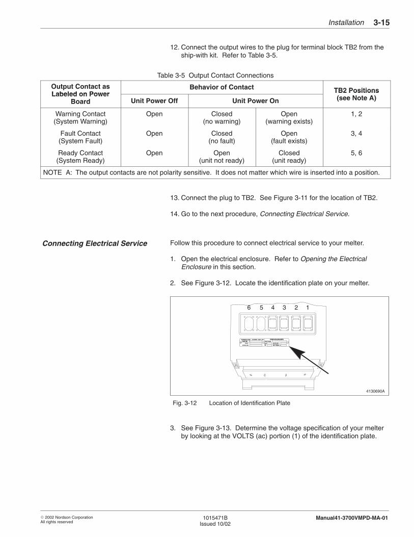
Follow this procedure to connect electrical service to your melter.
1. Open the electrical enclosure. Refer to Opening the ElectricalEnclosure in this section.
2. See Figure 3-12. Locate the identification plate on your melter.
4130690A
123456
Fig. 3-12 Location of Identification Plate
3. See Figure 3-13. Determine the voltage specification of your melterby looking at the VOLTS (ac) portion (1) of the identification plate.
Connecting Electrical Service
Installation3-16
� 2002 Nordson CorporationAll rights reserved
1015471BIssued 10/02
Manual41-3700VMPD-MA-01
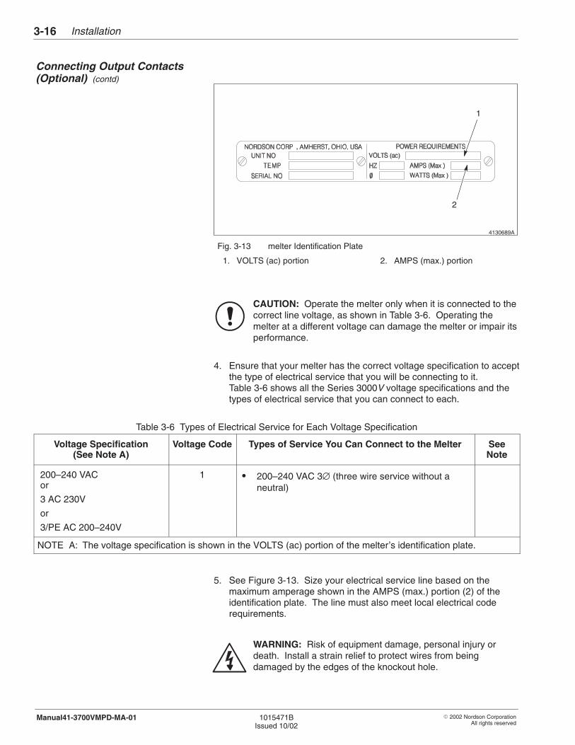
4130689A
1
2
Fig. 3-13 melter Identification Plate
1. VOLTS (ac) portion 2. AMPS (max.) portion
CAUTION: Operate the melter only when it is connected to thecorrect line voltage, as shown in Table 3-6. Operating themelter at a different voltage can damage the melter or impair itsperformance.
4. Ensure that your melter has the correct voltage specification to acceptthe type of electrical service that you will be connecting to it.Table 3-6 shows all the Series 3000V voltage specifications and thetypes of electrical service that you can connect to each.
Table 3-6 Types of Electrical Service for Each Voltage Specification
Voltage Specification(See Note A)
Voltage Code Types of Service You Can Connect to the Melter SeeNote
200–240 VACor
3 AC 230V
or
3/PE AC 200–240V
1 � 200–240 VAC 3∅ (three wire service without aneutral)
NOTE A: The voltage specification is shown in the VOLTS (ac) portion of the melter’s identification plate.
5. See Figure 3-13. Size your electrical service line based on themaximum amperage shown in the AMPS (max.) portion (2) of theidentification plate. The line must also meet local electrical coderequirements.
WARNING: Risk of equipment damage, personal injury ordeath. Install a strain relief to protect wires from beingdamaged by the edges of the knockout hole.
Connecting Output Contacts(Optional) (contd)
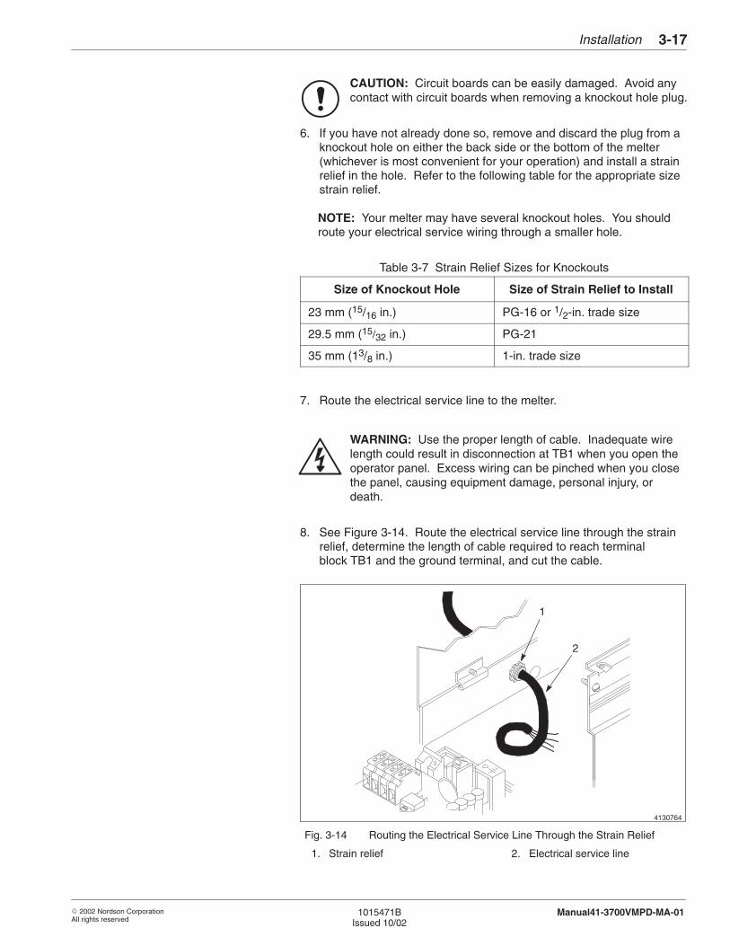
Installation 3-17
� 2002 Nordson CorporationAll rights reserved
1015471BIssued 10/02
Manual41-3700VMPD-MA-01
CAUTION: Circuit boards can be easily damaged. Avoid anycontact with circuit boards when removing a knockout hole plug.
6. If you have not already done so, remove and discard the plug from aknockout hole on either the back side or the bottom of the melter(whichever is most convenient for your operation) and install a strainrelief in the hole. Refer to the following table for the appropriate sizestrain relief.
NOTE: Your melter may have several knockout holes. You shouldroute your electrical service wiring through a smaller hole.
Table 3-7 Strain Relief Sizes for Knockouts
Size of Knockout Hole Size of Strain Relief to Install
23 mm (15/16 in.) PG-16 or 1/2-in. trade size
29.5 mm (15/32 in.) PG-21
35 mm (13/8 in.) 1-in. trade size
7. Route the electrical service line to the melter.
WARNING: Use the proper length of cable. Inadequate wirelength could result in disconnection at TB1 when you open theoperator panel. Excess wiring can be pinched when you closethe panel, causing equipment damage, personal injury, ordeath.
8. See Figure 3-14. Route the electrical service line through the strainrelief, determine the length of cable required to reach terminalblock TB1 and the ground terminal, and cut the cable.
4130764
1
2
Fig. 3-14 Routing the Electrical Service Line Through the Strain Relief
1. Strain relief 2. Electrical service line
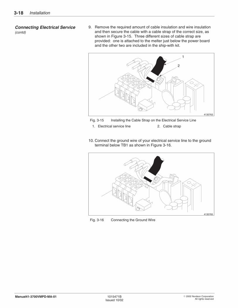
Installation3-18
� 2002 Nordson CorporationAll rights reserved
1015471BIssued 10/02
Manual41-3700VMPD-MA-01
9. Remove the required amount of cable insulation and wire insulationand then secure the cable with a cable strap of the correct size, asshown in Figure 3-15. Three different sizes of cable strap areprovided: one is attached to the melter just below the power boardand the other two are included in the ship-with kit.
4130763
1
2
Fig. 3-15 Installing the Cable Strap on the Electrical Service Line
1. Electrical service line 2. Cable strap
10. Connect the ground wire of your electrical service line to the groundterminal below TB1 as shown in Figure 3-16.
4130765
Fig. 3-16 Connecting the Ground Wire
Connecting Electrical Service(contd)
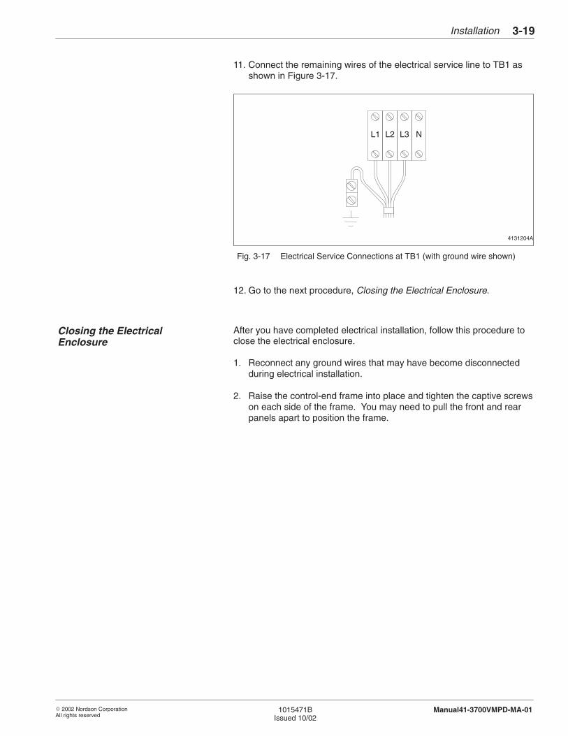
Installation 3-19
� 2002 Nordson CorporationAll rights reserved
1015471BIssued 10/02
Manual41-3700VMPD-MA-01
11. Connect the remaining wires of the electrical service line to TB1 asshown in Figure 3-17.
4131204A
L1 L2 L3 N
Fig. 3-17 Electrical Service Connections at TB1 (with ground wire shown)
12. Go to the next procedure, Closing the Electrical Enclosure.
After you have completed electrical installation, follow this procedure toclose the electrical enclosure.
1. Reconnect any ground wires that may have become disconnectedduring electrical installation.
2. Raise the control-end frame into place and tighten the captive screwson each side of the frame. You may need to pull the front and rearpanels apart to position the frame.
Closing the ElectricalEnclosure
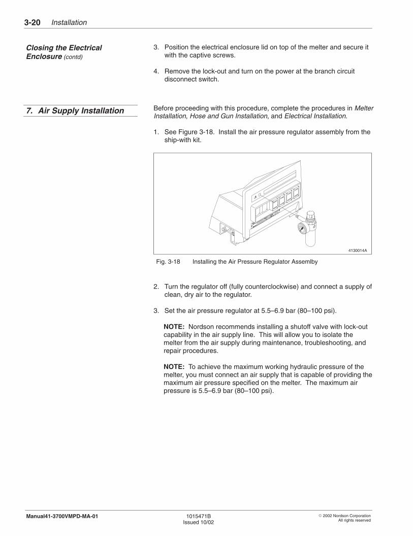
Installation3-20
� 2002 Nordson CorporationAll rights reserved
1015471BIssued 10/02
Manual41-3700VMPD-MA-01
3. Position the electrical enclosure lid on top of the melter and secure itwith the captive screws.
4. Remove the lock-out and turn on the power at the branch circuitdisconnect switch.
Before proceeding with this procedure, complete the procedures in MelterInstallation, Hose and Gun Installation, and Electrical Installation.
1. See Figure 3-18. Install the air pressure regulator assembly from theship-with kit.
4130014A
Fig. 3-18 Installing the Air Pressure Regulator Assemlby
2. Turn the regulator off (fully counterclockwise) and connect a supply ofclean, dry air to the regulator.
3. Set the air pressure regulator at 5.5–6.9 bar (80–100 psi).
NOTE: Nordson recommends installing a shutoff valve with lock-outcapability in the air supply line. This will allow you to isolate themelter from the air supply during maintenance, troubleshooting, andrepair procedures.
NOTE: To achieve the maximum working hydraulic pressure of themelter, you must connect an air supply that is capable of providing themaximum air pressure specified on the melter. The maximum airpressure is 5.5–6.9 bar (80–100 psi).
Closing the ElectricalEnclosure (contd)
7. Air Supply Installation
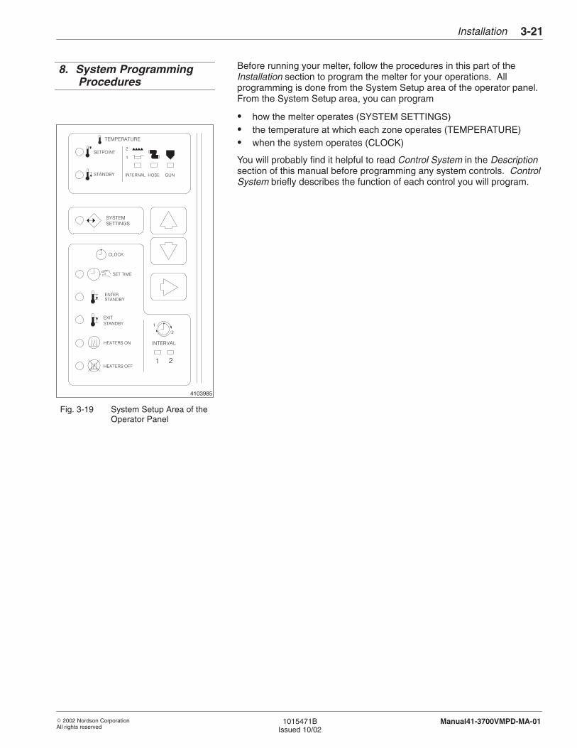
4103985
Installation 3-21
� 2002 Nordson CorporationAll rights reserved
1015471BIssued 10/02
Manual41-3700VMPD-MA-01
Before running your melter, follow the procedures in this part of theInstallation section to program the melter for your operations. Allprogramming is done from the System Setup area of the operator panel.From the System Setup area, you can program
� how the melter operates (SYSTEM SETTINGS)� the temperature at which each zone operates (TEMPERATURE)� when the system operates (CLOCK)
You will probably find it helpful to read Control System in the Descriptionsection of this manual before programming any system controls. ControlSystem briefly describes the function of each control you will program.
Fig. 3-19 System Setup Area of theOperator Panel
8. System ProgrammingProcedures
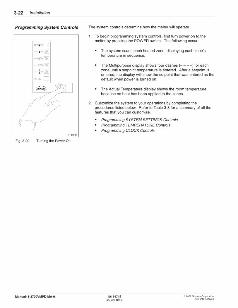
4103986
Installation3-22
� 2002 Nordson CorporationAll rights reserved
1015471BIssued 10/02
Manual41-3700VMPD-MA-01
The system controls determine how the melter will operate.
1. To begin programming system controls, first turn power on to themelter by pressing the POWER switch. The following occur:
� The system scans each heated zone, displaying each zone’stemperature in sequence.
� The Multipurpose display shows four dashes (– – – –) for eachzone until a setpoint temperature is entered. After a setpoint isentered, the display will show the setpoint that was entered as thedefault when power is turned on.
� The Actual Temperature display shows the room temperaturebecause no heat has been applied to the zones.
2. Customize the system to your operations by completing theprocedures listed below. Refer to Table 3-8 for a summary of all thefeatures that you can customize.
� Programming SYSTEM SETTINGS Controls� Programming TEMPERATURE Controls� Programming CLOCK Controls
Fig. 3-20 Turning the Power On
Programming System Controls
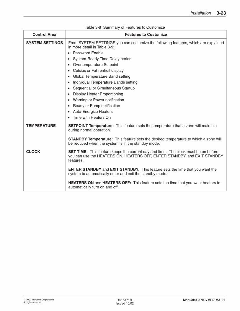
Installation 3-23
� 2002 Nordson CorporationAll rights reserved
1015471BIssued 10/02
Manual41-3700VMPD-MA-01
Table 3-8 Summary of Features to Customize
Control Area Features to Customize
SYSTEM SETTINGS From SYSTEM SETTINGS you can customize the following features, which are explainedin more detail in Table 3-9:
• Password Enable
• System-Ready Time Delay period
• Overtemperature Setpoint
• Celsius or Fahrenheit display
• Global Temperature Band setting
• Individual Temperature Bands setting
• Sequential or Simultaneous Startup
• Display Heater Proportioning
• Warning or Power notification
• Ready or Pump notification
• Auto-Energize Heaters
• Time with Heaters On
TEMPERATURE SETPOINT Temperature: This feature sets the temperature that a zone will maintainduring normal operation.
STANDBY Temperature: This feature sets the desired temperature to which a zone willbe reduced when the system is in the standby mode.
CLOCK SET TIME: This feature keeps the current day and time. The clock must be on beforeyou can use the HEATERS ON, HEATERS OFF, ENTER STANDBY, and EXIT STANDBYfeatures.
ENTER STANDBY and EXIT STANDBY: This feature sets the time that you want thesystem to automatically enter and exit the standby mode.
HEATERS ON and HEATERS OFF: This feature sets the time that you want heaters toautomatically turn on and off.
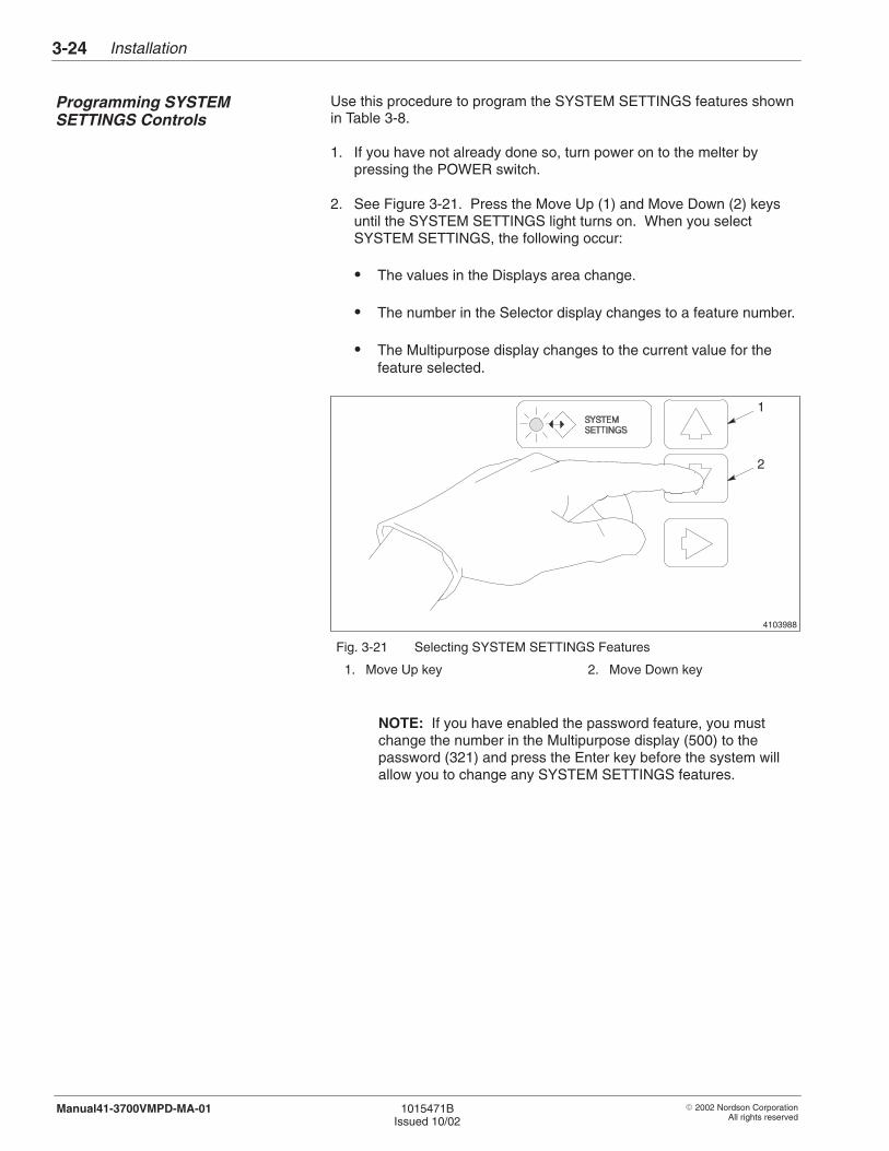
Installation3-24
� 2002 Nordson CorporationAll rights reserved
1015471BIssued 10/02
Manual41-3700VMPD-MA-01
Use this procedure to program the SYSTEM SETTINGS features shownin Table 3-8.
1. If you have not already done so, turn power on to the melter bypressing the POWER switch.
2. See Figure 3-21. Press the Move Up (1) and Move Down (2) keysuntil the SYSTEM SETTINGS light turns on. When you selectSYSTEM SETTINGS, the following occur:
� The values in the Displays area change.
� The number in the Selector display changes to a feature number.
� The Multipurpose display changes to the current value for thefeature selected.
4103988
1
2
Fig. 3-21 Selecting SYSTEM SETTINGS Features
1. Move Up key 2. Move Down key
NOTE: If you have enabled the password feature, you mustchange the number in the Multipurpose display (500) to thepassword (321) and press the Enter key before the system willallow you to change any SYSTEM SETTINGS features.
Programming SYSTEMSETTINGS Controls
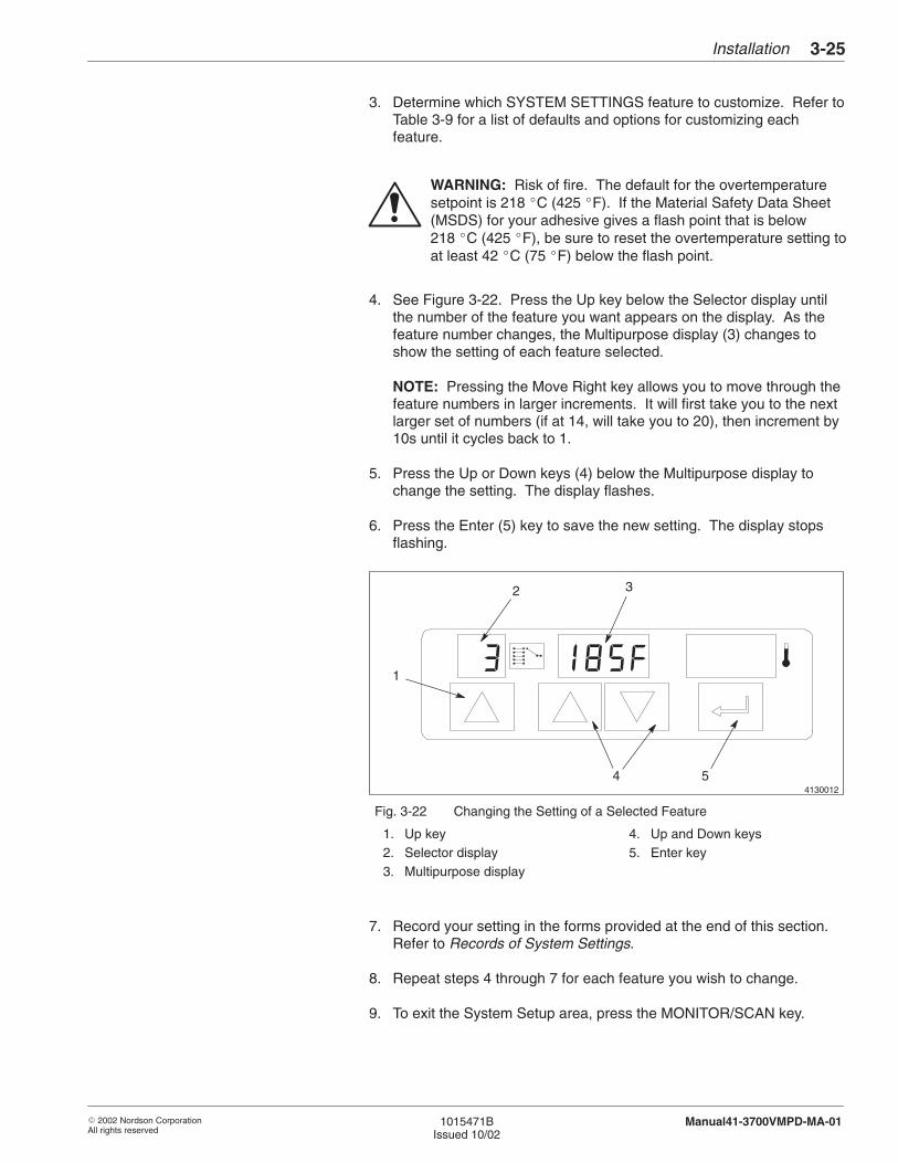
Installation 3-25
� 2002 Nordson CorporationAll rights reserved
1015471BIssued 10/02
Manual41-3700VMPD-MA-01
3. Determine which SYSTEM SETTINGS feature to customize. Refer toTable 3-9 for a list of defaults and options for customizing eachfeature.
WARNING: Risk of fire. The default for the overtemperaturesetpoint is 218 �C (425 �F). If the Material Safety Data Sheet(MSDS) for your adhesive gives a flash point that is below218 �C (425 �F), be sure to reset the overtemperature setting toat least 42 �C (75 �F) below the flash point.
4. See Figure 3-22. Press the Up key below the Selector display untilthe number of the feature you want appears on the display. As thefeature number changes, the Multipurpose display (3) changes toshow the setting of each feature selected.
NOTE: Pressing the Move Right key allows you to move through thefeature numbers in larger increments. It will first take you to the nextlarger set of numbers (if at 14, will take you to 20), then increment by10s until it cycles back to 1.
5. Press the Up or Down keys (4) below the Multipurpose display tochange the setting. The display flashes.
6. Press the Enter (5) key to save the new setting. The display stopsflashing.
4130012
2 3
4 5
1
Fig. 3-22 Changing the Setting of a Selected Feature
1. Up key2. Selector display3. Multipurpose display
4. Up and Down keys5. Enter key
7. Record your setting in the forms provided at the end of this section.Refer to Records of System Settings.
8. Repeat steps 4 through 7 for each feature you wish to change.
9. To exit the System Setup area, press the MONITOR/SCAN key.
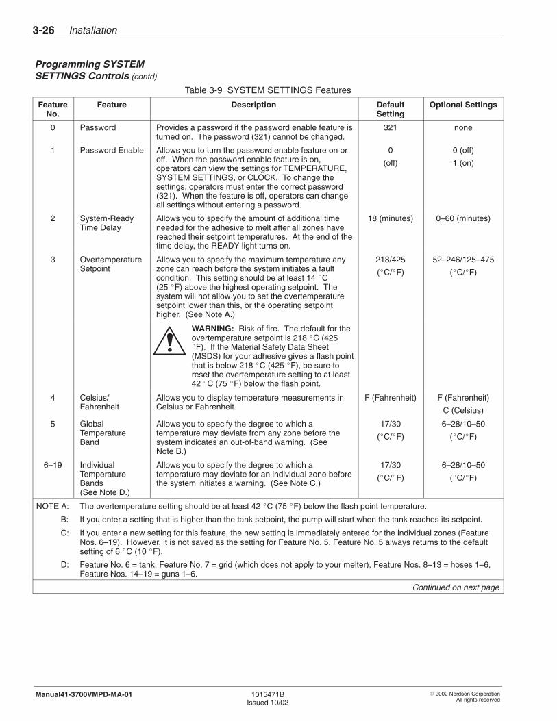
Installation3-26
� 2002 Nordson CorporationAll rights reserved
1015471BIssued 10/02
Manual41-3700VMPD-MA-01
Table 3-9 SYSTEM SETTINGS Features
FeatureNo.
Feature Description DefaultSetting
Optional Settings
0 Password Provides a password if the password enable feature isturned on. The password (321) cannot be changed.
321 none
1 Password Enable Allows you to turn the password enable feature on oroff. When the password enable feature is on,operators can view the settings for TEMPERATURE,SYSTEM SETTINGS, or CLOCK. To change thesettings, operators must enter the correct password(321). When the feature is off, operators can changeall settings without entering a password.
0
(off)
0 (off)
1 (on)
2 System-ReadyTime Delay
Allows you to specify the amount of additional timeneeded for the adhesive to melt after all zones havereached their setpoint temperatures. At the end of thetime delay, the READY light turns on.
18 (minutes) 0–60 (minutes)
3 OvertemperatureSetpoint
Allows you to specify the maximum temperature anyzone can reach before the system initiates a faultcondition. This setting should be at least 14 �C(25 �F) above the highest operating setpoint. Thesystem will not allow you to set the overtemperaturesetpoint lower than this, or the operating setpointhigher. (See Note A.)
218/425
(�C/�F)
52–246/125–475
(�C/�F)
WARNING: Risk of fire. The default for theovertemperature setpoint is 218 �C (425�F). If the Material Safety Data Sheet(MSDS) for your adhesive gives a flash pointthat is below 218 �C (425 �F), be sure toreset the overtemperature setting to at least42 �C (75 �F) below the flash point.
4 Celsius/Fahrenheit
Allows you to display temperature measurements inCelsius or Fahrenheit.
F (Fahrenheit) F (Fahrenheit)
C (Celsius)
5 GlobalTemperatureBand
Allows you to specify the degree to which atemperature may deviate from any zone before thesystem indicates an out-of-band warning. (SeeNote B.)
17/30
(�C/�F)
6–28/10–50
(�C/�F)
6–19 IndividualTemperatureBands(See Note D.)
Allows you to specify the degree to which atemperature may deviate for an individual zone beforethe system initiates a warning. (See Note C.)
17/30
(�C/�F)
6–28/10–50
(�C/�F)
NOTE A: The overtemperature setting should be at least 42 �C (75 �F) below the flash point temperature.
B: If you enter a setting that is higher than the tank setpoint, the pump will start when the tank reaches its setpoint.
C: If you enter a new setting for this feature, the new setting is immediately entered for the individual zones (FeatureNos. 6–19). However, it is not saved as the setting for Feature No. 5. Feature No. 5 always returns to the defaultsetting of 6 �C (10 �F).
D: Feature No. 6 = tank, Feature No. 7 = grid (which does not apply to your melter), Feature Nos. 8–13 = hoses 1–6,Feature Nos. 14–19 = guns 1–6.
Continued on next page
Programming SYSTEMSETTINGS Controls (contd)
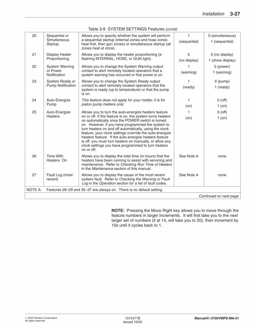
Installation 3-27
� 2002 Nordson CorporationAll rights reserved
1015471BIssued 10/02
Manual41-3700VMPD-MA-01
Table 3-9 SYSTEM SETTINGS Features (contd)
20 Sequential orSimultaneousStartup
Allows you to specify whether the system will performa sequential startup (internal zones and hose zonesheat first, then gun zones) or simultaneous startup (allzones heat at once).
1
(sequential)
0 (simultaneous)
1 (sequential)
21 Display HeaterProportioning
Allows you to display the heater proportioning (aflashing INTERNAL, HOSE, or GUN light).
0
(no display)
0 (no display)
1 (show display)
22 System Warningor PowerNotification
Allows you to change the System Warning outputcontact to alert remotely located operators that asystem warning has occurred or that power is on.
1
(warning)
0 (power)
1 (warning)
23 System Ready orPump Notification
Allows you to change the System Ready outputcontact to alert remotely located operators that thesystem is ready (up to temperature) or that the pumpis on.
1
(ready)
0 (pump)
1 (ready)
24 Auto-EnergizePump
This feature does not apply for your melter, it is forpiston pump melters only:
1
(on)
0 (off)
1 (on)
25 Auto-EnergizeHeaters
Allows you to turn the auto-energize heaters featureon or off. If the feature is on, the system turns heaterson automatically once the POWER switch is turnedon. However, if you have programmed the system toturn heaters on and off automatically, using the clockfeature, your clock settings override the auto-energizeheaters feature. If the auto-energize heaters featureis off, you must turn heaters on manually, or allow anyclock settings you have programmed to turn heaterson or off.
1
(on)
0 (off)
1 (on)
26 Time WithHeaters On
Allows you to display the total time (in hours) that theheaters have been running to assist with servicing andmaintenance. Refer to Checking Run Time of Heatersin the Maintenance section of this manual.
See Note A none
27 Fault Log (mostrecent)
Allows you to display the cause of the most recentsystem fault. Refer to Checking the Warning or FaultLog in the Operation section for a list of fault codes.
See Note A none
NOTE A: Features 26–29 and 35–37 are always on. There is no default setting.
Continued on next page
NOTE: Pressing the Move Right key allows you to move through thefeature numbers in larger increments. It will first take you to the nextlarger set of numbers (if at 14, will take you to 20), then increment by10s until it cycles back to 1.
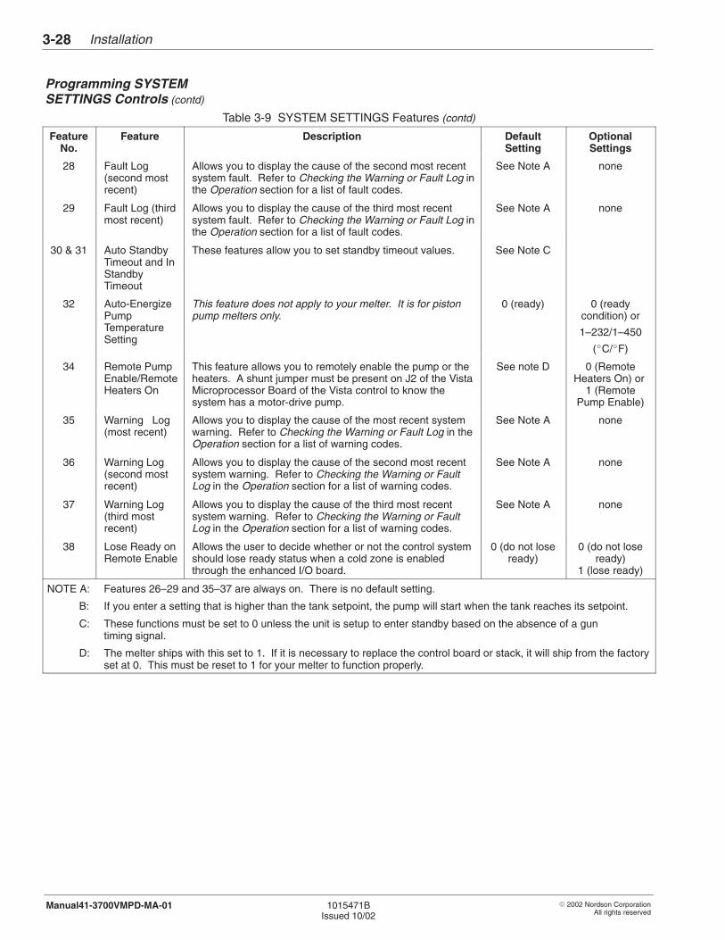
Installation3-28
� 2002 Nordson CorporationAll rights reserved
1015471BIssued 10/02
Manual41-3700VMPD-MA-01
Table 3-9 SYSTEM SETTINGS Features (contd)
FeatureNo.
Feature Description DefaultSetting
OptionalSettings
28 Fault Log(second mostrecent)
Allows you to display the cause of the second most recentsystem fault. Refer to Checking the Warning or Fault Log inthe Operation section for a list of fault codes.
See Note A none
29 Fault Log (thirdmost recent)
Allows you to display the cause of the third most recentsystem fault. Refer to Checking the Warning or Fault Log inthe Operation section for a list of fault codes.
See Note A none
30 & 31 Auto StandbyTimeout and InStandbyTimeout
These features allow you to set standby timeout values. See Note C
32 Auto-EnergizePumpTemperatureSetting
This feature does not apply to your melter. It is for pistonpump melters only.
0 (ready) 0 (readycondition) or
1–232/1–450
(�C/�F)
34 Remote PumpEnable/RemoteHeaters On
This feature allows you to remotely enable the pump or theheaters. A shunt jumper must be present on J2 of the VistaMicroprocessor Board of the Vista control to know thesystem has a motor-drive pump.
See note D 0 (RemoteHeaters On) or
1 (RemotePump Enable)
35 Warning Log(most recent)
Allows you to display the cause of the most recent systemwarning. Refer to Checking the Warning or Fault Log in theOperation section for a list of warning codes.
See Note A none
36 Warning Log(second mostrecent)
Allows you to display the cause of the second most recentsystem warning. Refer to Checking the Warning or FaultLog in the Operation section for a list of warning codes.
See Note A none
37 Warning Log(third mostrecent)
Allows you to display the cause of the third most recentsystem warning. Refer to Checking the Warning or FaultLog in the Operation section for a list of warning codes.
See Note A none
38 Lose Ready onRemote Enable
Allows the user to decide whether or not the control systemshould lose ready status when a cold zone is enabledthrough the enhanced I/O board.
0 (do not loseready)
0 (do not loseready)
1 (lose ready)
NOTE A: Features 26–29 and 35–37 are always on. There is no default setting.
B: If you enter a setting that is higher than the tank setpoint, the pump will start when the tank reaches its setpoint.
C: These functions must be set to 0 unless the unit is setup to enter standby based on the absence of a gun timing signal.
D: The melter ships with this set to 1. If it is necessary to replace the control board or stack, it will ship from the factoryset at 0. This must be reset to 1 for your melter to function properly.
Programming SYSTEMSETTINGS Controls (contd)
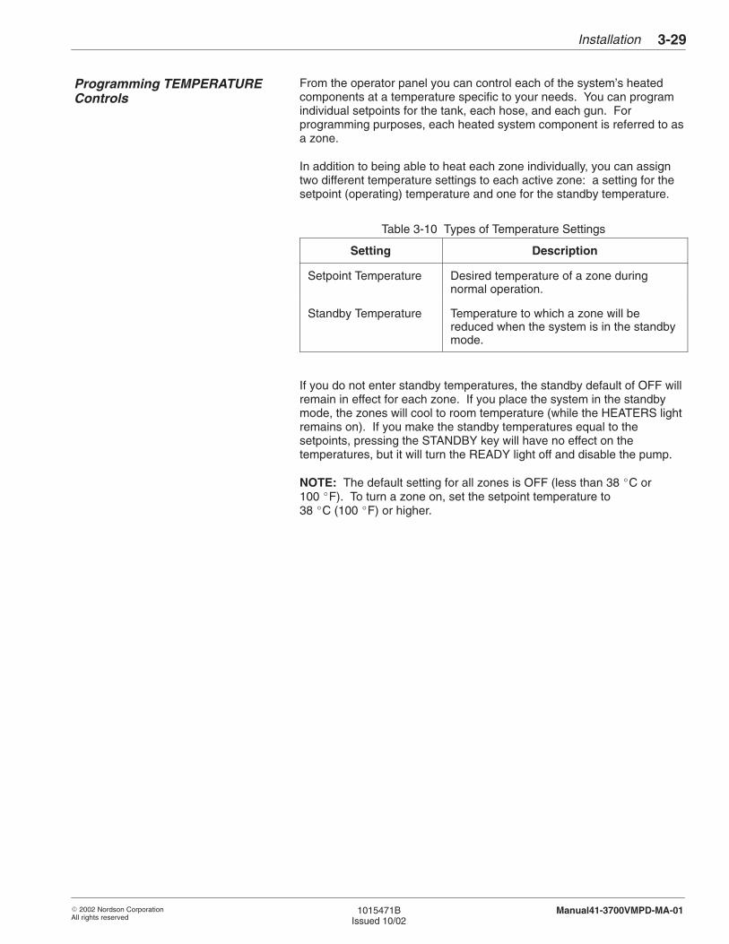
Installation 3-29
� 2002 Nordson CorporationAll rights reserved
1015471BIssued 10/02
Manual41-3700VMPD-MA-01
From the operator panel you can control each of the system’s heatedcomponents at a temperature specific to your needs. You can programindividual setpoints for the tank, each hose, and each gun. Forprogramming purposes, each heated system component is referred to asa zone.
In addition to being able to heat each zone individually, you can assigntwo different temperature settings to each active zone: a setting for thesetpoint (operating) temperature and one for the standby temperature.
Table 3-10 Types of Temperature Settings
Setting Description
Setpoint Temperature Desired temperature of a zone duringnormal operation.
Standby Temperature Temperature to which a zone will bereduced when the system is in the standbymode.
If you do not enter standby temperatures, the standby default of OFF willremain in effect for each zone. If you place the system in the standbymode, the zones will cool to room temperature (while the HEATERS lightremains on). If you make the standby temperatures equal to thesetpoints, pressing the STANDBY key will have no effect on thetemperatures, but it will turn the READY light off and disable the pump.
NOTE: The default setting for all zones is OFF (less than 38 �C or100 �F). To turn a zone on, set the setpoint temperature to38 �C (100 �F) or higher.
Programming TEMPERATUREControls
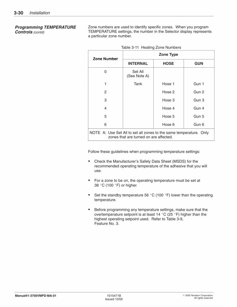
Installation3-30
� 2002 Nordson CorporationAll rights reserved
1015471BIssued 10/02
Manual41-3700VMPD-MA-01
Zone numbers are used to identify specific zones. When you programTEMPERATURE settings, the number in the Selector display representsa particular zone number.
Table 3-11 Heating Zone Numbers
Zone N mberZone Type
Zone NumberINTERNAL HOSE GUN
0 Set All(See Note A)
1 Tank Hose 1 Gun 1
2 Hose 2 Gun 2
3 Hose 3 Gun 3
4 Hose 4 Gun 4
5 Hose 5 Gun 5
6 Hose 6 Gun 6
NOTE A: Use Set All to set all zones to the same temperature. Onlyzones that are turned on are affected.
Follow these guidelines when programming temperature settings:
� Check the Manufacturer’s Safety Data Sheet (MSDS) for therecommended operating temperature of the adhesive that you willuse.
� For a zone to be on, the operating temperature must be set at38 �C (100 �F) or higher.
� Set the standby temperature 56 �C (100 �F) lower than the operatingtemperature.
� Before programming any temperature settings, make sure that theovertemperature setpoint is at least 14 �C (25 �F) higher than thehighest operating setpoint used. Refer to Table 3-9,Feature No. 3.
Programming TEMPERATUREControls (contd)
Installation 3-31
� 2002 Nordson CorporationAll rights reserved
1015471BIssued 10/02
Manual41-3700VMPD-MA-01
Use this tip to program temperature settings quickly:
Zone Procedure
All zones to the sametemperature
Follow the procedure To Program AllZones to the Same Temperature.
Most zones to the sametemperature
1. First, follow the procedure ToProgram All Zones to the SameTemperature.
2. Then, follow the procedure ToProgram Setpoint and StandbyTemperatures Individually tochange the settings that you wish.
To Program All Zones to the Same Temperature
Follow this procedure to set all zones to the same temperature. Also usethis procedure along with the procedure To Program Setpoint andStandby Temperatures Individually to set most zones to the sametemperature.
NOTE: This procedure works only for zones that have been previouslyturned on. The default setting for all zones is OFF. To turn a zone on,refer to the next procedure, To Program Setpoint and StandbyTemperatures Individually, and set the temperature of each zone youwant to turn on to at least 38 �C (100 �F).
1. If you have not already done so, turn power on to the melter bypressing the POWER switch.
2. See Figure 3-23. In the System Setup area, press the Move Up (1)and Move Down (2) keys until the SETPOINT or STANDBY light turnson. The system defaults to the internal-zone type and the INTERNALlight turns on.
NOTE: If you have enabled the password feature, you must changethe number in the Multipurpose display (500) to the password (321)and press the Enter key before the system will allow you to changeany of the temperature setpoints.
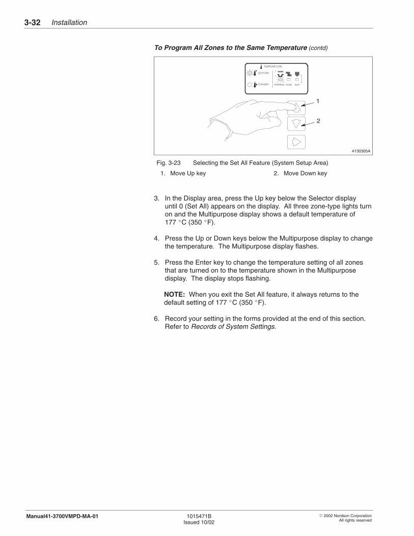
Installation3-32
� 2002 Nordson CorporationAll rights reserved
1015471BIssued 10/02
Manual41-3700VMPD-MA-01
To Program All Zones to the Same Temperature (contd)
4130305A
1
2
Fig. 3-23 Selecting the Set All Feature (System Setup Area)
1. Move Up key 2. Move Down key
3. In the Display area, press the Up key below the Selector displayuntil 0 (Set All) appears on the display. All three zone-type lights turnon and the Multipurpose display shows a default temperature of177 �C (350 �F).
4. Press the Up or Down keys below the Multipurpose display to changethe temperature. The Multipurpose display flashes.
5. Press the Enter key to change the temperature setting of all zonesthat are turned on to the temperature shown in the Multipurposedisplay. The display stops flashing.
NOTE: When you exit the Set All feature, it always returns to thedefault setting of 177 �C (350 �F).
6. Record your setting in the forms provided at the end of this section.Refer to Records of System Settings.

Installation 3-33
� 2002 Nordson CorporationAll rights reserved
1015471BIssued 10/02
Manual41-3700VMPD-MA-01
To Program Setpoint and Standby Temperatures Individually
Follow this procedure to set the setpoint and standby temperatures foreach zone.
1. If you have not already done so, turn power on to the melter bypressing the POWER switch.
2. In the System Setup area, press the Move Up and Move Down keysuntil the SETPOINT or STANDBY light turns on. The system defaultsto the internal zone type and the INTERNAL light turns on.
NOTE: If you have enabled the password feature, you must changethe number in the Multipurpose display (500) to the password (321)and press the Enter key before the system will allow you to changeany of the temperature setpoints.
3. If you want to select the hose-zone type or the gun-zone type insteadof the internal-zone type, press the Move Right key until the lightbeneath the zone type you want to set turns on.
4. See Figure 3-24. In the Displays area, press the Up key (1) belowthe Selector display (2) until the zone number you want appears onthe display. (Refer to Table 3-11.) The Multipurpose display (3)changes to show the current temperature setting for the zone youselected.
5. In the Displays area, press the Up or Down key (4) below theMultipurpose display to change the temperature. The display flashes.
NOTE: Pressing the Up or Down keys in the Displays area oncechanges the number shown in increments of one. Pressing andholding the key changes the number in increments of five.
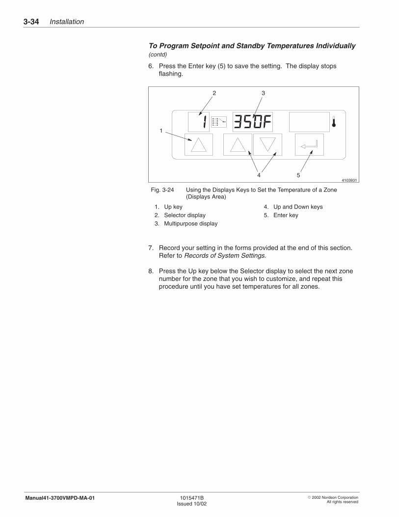
Installation3-34
� 2002 Nordson CorporationAll rights reserved
1015471BIssued 10/02
Manual41-3700VMPD-MA-01
To Program Setpoint and Standby Temperatures Individually(contd)
6. Press the Enter key (5) to save the setting. The display stopsflashing.
4103931
2 3
4 5
1
Fig. 3-24 Using the Displays Keys to Set the Temperature of a Zone(Displays Area)
1. Up key2. Selector display3. Multipurpose display
4. Up and Down keys5. Enter key
7. Record your setting in the forms provided at the end of this section.Refer to Records of System Settings.
8. Press the Up key below the Selector display to select the next zonenumber for the zone that you wish to customize, and repeat thisprocedure until you have set temperatures for all zones.
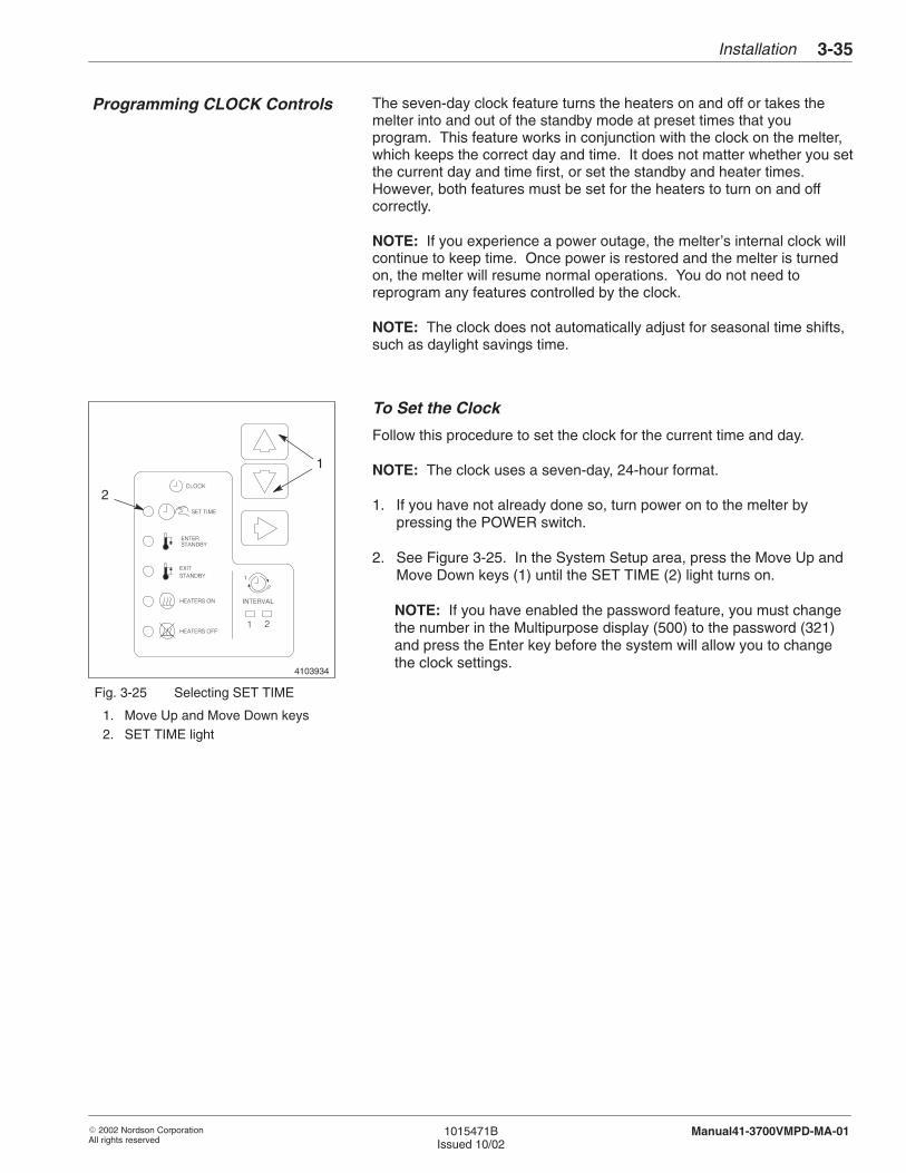
4103934
2
1
Installation 3-35
� 2002 Nordson CorporationAll rights reserved
1015471BIssued 10/02
Manual41-3700VMPD-MA-01
The seven-day clock feature turns the heaters on and off or takes themelter into and out of the standby mode at preset times that youprogram. This feature works in conjunction with the clock on the melter,which keeps the correct day and time. It does not matter whether you setthe current day and time first, or set the standby and heater times.However, both features must be set for the heaters to turn on and offcorrectly.
NOTE: If you experience a power outage, the melter’s internal clock willcontinue to keep time. Once power is restored and the melter is turnedon, the melter will resume normal operations. You do not need toreprogram any features controlled by the clock.
NOTE: The clock does not automatically adjust for seasonal time shifts,such as daylight savings time.
To Set the Clock
Follow this procedure to set the clock for the current time and day.
NOTE: The clock uses a seven-day, 24-hour format.
1. If you have not already done so, turn power on to the melter bypressing the POWER switch.
2. See Figure 3-25. In the System Setup area, press the Move Up andMove Down keys (1) until the SET TIME (2) light turns on.
NOTE: If you have enabled the password feature, you must changethe number in the Multipurpose display (500) to the password (321)and press the Enter key before the system will allow you to changethe clock settings.
Fig. 3-25 Selecting SET TIME
1. Move Up and Move Down keys2. SET TIME light
Programming CLOCK Controls
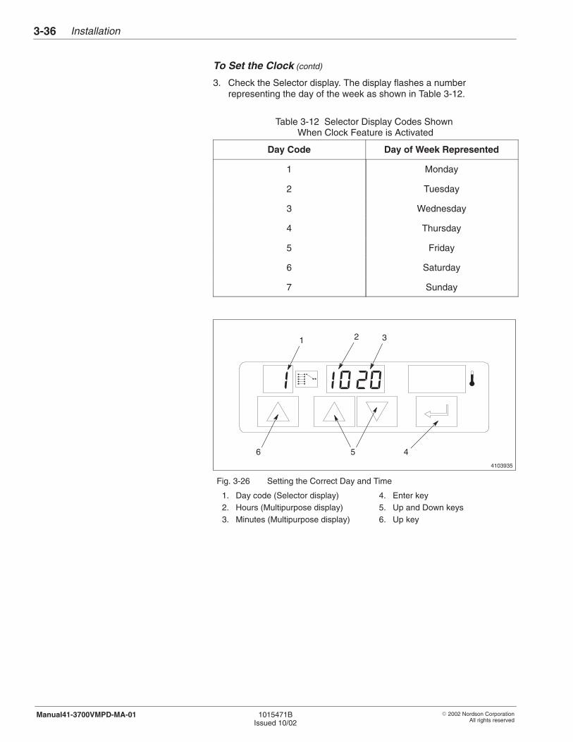
Installation3-36
� 2002 Nordson CorporationAll rights reserved
1015471BIssued 10/02
Manual41-3700VMPD-MA-01
To Set the Clock (contd)
3. Check the Selector display. The display flashes a numberrepresenting the day of the week as shown in Table 3-12.
Table 3-12 Selector Display Codes Shown When Clock Feature is Activated
Day Code Day of Week Represented
1 Monday
2 Tuesday
3 Wednesday
4 Thursday
5 Friday
6 Saturday
7 Sunday
4103935
1 2 3
6 5 4
Fig. 3-26 Setting the Correct Day and Time
1. Day code (Selector display)2. Hours (Multipurpose display)3. Minutes (Multipurpose display)
4. Enter key5. Up and Down keys6. Up key
Installation 3-37
� 2002 Nordson CorporationAll rights reserved
1015471BIssued 10/02
Manual41-3700VMPD-MA-01
4. See Figure 3-26. Check that the day code is correct.
Correct? Action:
Yes Press the Enter key (4) to save the setting.
No Press the Up key (6) below the Selector display untilthe correct code appears on the display; then pressthe Enter key to save the setting.
5. When you press the Enter key, the Selector display stops flashingand the hour (2) shown in the Multipurpose display begins flashing.Check that the hour shown in the Multipurpose display is correct.
NOTE: Clock hours must be set to come on between 01:00 and24:00 hours. If the clock is set from 00:01 to 00:59, it will not operate.
Correct? Action:
Yes Press the Enter key to save the setting.
No Press the Up or Down key below the Multipurposedisplay until the correct hour appears on the display;then press the Enter key to save the setting.
6. When you press the Enter key, the hour shown in the Multipurposedisplay stops flashing and the minutes shown begin flashing. Checkthat the minutes shown in the Multipurpose display are correct.
Correct? Action:
Yes Press the Enter key to save the setting.
No Press the Up or Down key below the Multipurposedisplay until the correct minutes appear on the display;then press the Enter key to save the setting.
NOTE: Once the clock is set, all displays stop flashing.
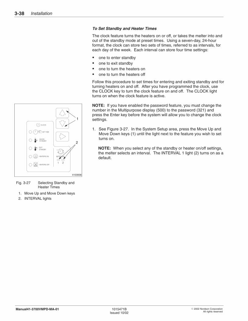
4103936
1
2
Installation3-38
� 2002 Nordson CorporationAll rights reserved
1015471BIssued 10/02
Manual41-3700VMPD-MA-01
To Set Standby and Heater Times
The clock feature turns the heaters on or off, or takes the melter into andout of the standby mode at preset times. Using a seven-day, 24-hourformat, the clock can store two sets of times, referred to as intervals, foreach day of the week. Each interval can store four time settings:
� one to enter standby� one to exit standby� one to turn the heaters on� one to turn the heaters off
Follow this procedure to set times for entering and exiting standby and forturning heaters on and off. After you have programmed the clock, usethe CLOCK key to turn the clock feature on and off. The CLOCK lightturns on when the clock feature is active.
NOTE: If you have enabled the password feature, you must change thenumber in the Multipurpose display (500) to the password (321) andpress the Enter key before the system will allow you to change the clocksettings.
1. See Figure 3-27. In the System Setup area, press the Move Up andMove Down keys (1) until the light next to the feature you wish to setturns on.
NOTE: When you select any of the standby or heater on/off settings,the melter selects an interval. The INTERVAL 1 light (2) turns on as adefault.
Fig. 3-27 Selecting Standby andHeater Times
1. Move Up and Move Down keys2. INTERVAL lights

Installation 3-39
� 2002 Nordson CorporationAll rights reserved
1015471BIssued 10/02
Manual41-3700VMPD-MA-01
2. Check the Selector display. The display flashes a number (the daycode) representing the day of the week as shown in Table 3-13.
Table 3-13 Selector Display Codes Shown When Clock Feature is Activated
Day Code Day of Week Represented
1 Monday
2 Tuesday
3 Wednesday
4 Thursday
5 Friday
6 Saturday
7 Sunday
4103935
1 2 3
6 5 4
Fig. 3-28 Setting the Correct Day and Time
1. Day code (Selector display)2. Hours (Multipurpose display)3. Minutes (Multipurpose display)
4. Enter key5. Up and Down keys6. Up key
Installation3-40
� 2002 Nordson CorporationAll rights reserved
1015471BIssued 10/02
Manual41-3700VMPD-MA-01
To Set Standby and Heater Times (contd)
3. See Figure 3-28. Press the Up key (6) below the Selector display toselect the day code (1) for which you want to set a time.
4. Press the Enter key (4) to save the day code setting. The Selectordisplay stops flashing and the hour (2) shown in the Multipurposedisplay flashes.
5. Press the Up or Down keys (5) below the Multipurpose display untilthe hour for which you want to set a time appears in the display.
6. Press the Enter key to save the hour setting. The hour shown in theMultipurpose display stops flashing and the minutes flash.
7. Press the Up or Down keys until the minutes (3) for which you want toset a time appear on the Multipurpose display.
8. Press the Enter key to save the minutes setting. All displays stopflashing.
9. Record your setting in the forms provided at the end of this section.Refer to Records of System Settings.
10. To set a second time for the same day, press the Move Right key untilthe INTERVAL 2 light turns on. Press the Enter key to save the dayand repeat steps 5 through 9.
To Change a Standby or Heater Time
To change a set time, follow the procedure for setting the standby andheater times.
Installation 3-41
� 2002 Nordson CorporationAll rights reserved
1015471BIssued 10/02
Manual41-3700VMPD-MA-01
To Delete a Standby or Heater Time
Follow this procedure to delete a Standby or Heater set time.
1. From the System Setup area, press the Move Up and Move Downkeys until the light next to the feature you wish to change turns on.
NOTE: If you have enabled the password feature, you must changethe number in the Multipurpose display (500) to the password (321)and press the Enter key before the system will allow you to changethe clock settings.
2. Check the Selector display. The display flashes the day coderepresenting a day of the week.
3. Refer to Table 3-13, and press the Up key below the Selector displayuntil the day code of the day that you want to change appears in theSelector display.
4. Press the Enter key to save the setting. The Selector display stopsflashing and the hour shown in the Multipurpose display flashes.
5. Press the Up or Down keys below the Multipurpose display until fourdashes (– – – –) appear on the display. (The dashes indicate that nosetting has been entered.)
6. Press the Enter key to save the setting. All displays stop flashing.
7. Record your setting in the forms provided at the end of this section.Refer to Records of System Settings.
To Delete Times for an Entire Day
To delete times for an entire day, follow the procedure To Delete aStandby or Heater Time and turn the clock off for each feature: enteringstandby, exiting standby, turning heaters on, turning heaters off.
Installation3-42
� 2002 Nordson CorporationAll rights reserved
1015471BIssued 10/02
Manual41-3700VMPD-MA-01
An Example of How to Use the Seven-Day Clock Feature
At one company, the production line runs for two shifts each day andshuts down on weekends. Both shifts shut down for 45 minutes twiceeach day: once at 12:00 noon for lunch and again at 6:00 in the eveningfor dinner. By using the clock feature, the company can have the melterstart and stop by setting the clock feature to
� Put the melter into the standby mode (ENTER STANDBY) at 12:00P.M. (INTERVAL 1) and again at 6:00 P.M. (INTERVAL 2).
� Take the melter out of the standby mode (EXIT STANDBY) at 12:30P.M. (INTERVAL 1) and at 6:30 P.M. (INTERVAL 2), allowing 15minutes for the system to reach application temperature.
� Turn the heaters on (HEATERS ON) Monday through Friday 30minutes before the start of the first shift (INTERVAL 1).
� Turn the heaters off (HEATERS OFF) Monday through Friday at theend of the second shift (INTERVAL 1).
NOTE: The clock is not set for Saturday or Sunday when the company isclosed.
Installation 3-43
� 2002 Nordson CorporationAll rights reserved
1015471BIssued 10/02
Manual41-3700VMPD-MA-01
Follow these procedures to flush the system and prepare it for firstoperation. This part of the Installation section also includes theprocedure for adjusting the pressure control valve on gear pump melters.
WARNING: Allow only qualified personnel to operate themelter.
1. If you have not already done so, program your melter. Refer toSystem Programming Procedures in this section.
2. Fill the tank with adhesive. Refer to Checking the Adhesive Leveland Filling the Tank in the Operation section.
3. Flush the system. Refer to Flushing the System in the Maintenancesection.
9. System Preparation
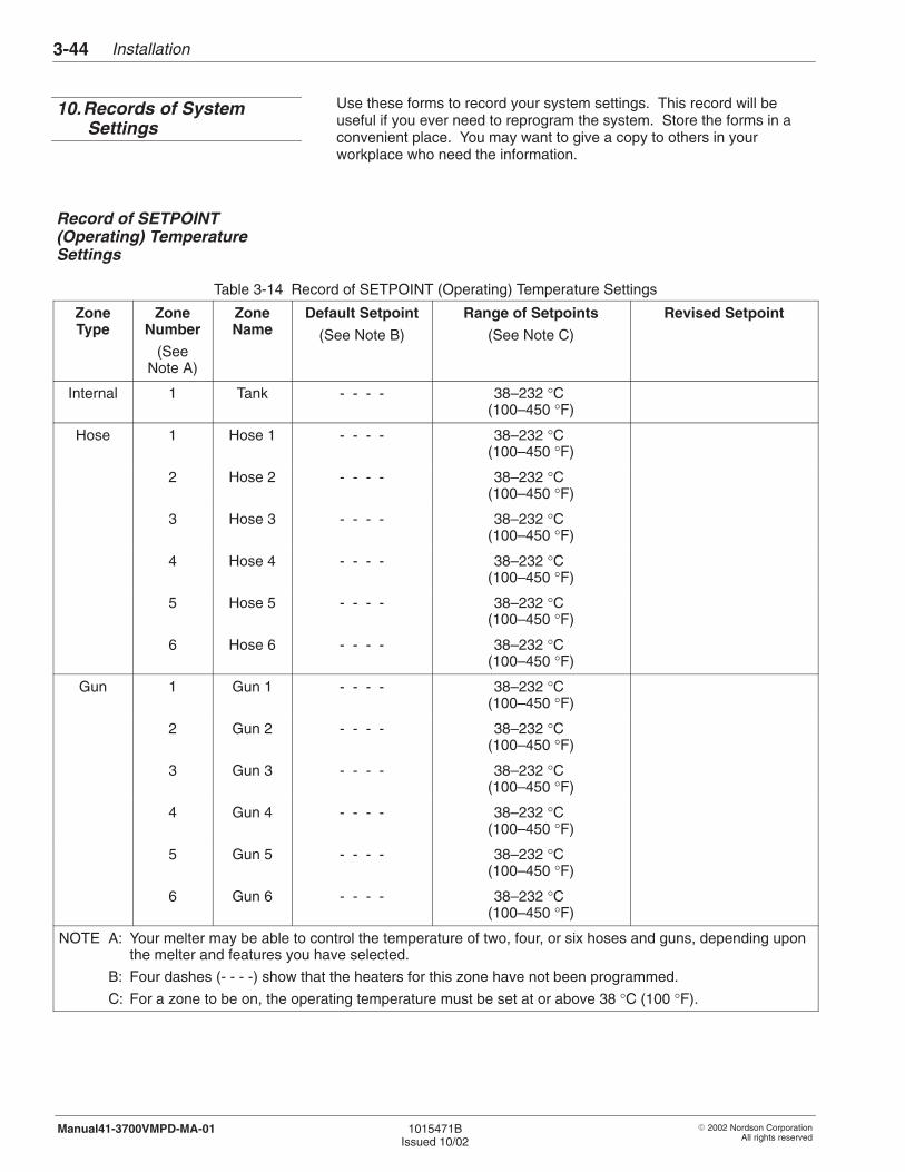
Installation3-44
� 2002 Nordson CorporationAll rights reserved
1015471BIssued 10/02
Manual41-3700VMPD-MA-01
Use these forms to record your system settings. This record will beuseful if you ever need to reprogram the system. Store the forms in aconvenient place. You may want to give a copy to others in yourworkplace who need the information.
Table 3-14 Record of SETPOINT (Operating) Temperature Settings
ZoneType
ZoneNumber
(SeeNote A)
ZoneName
Default Setpoint
(See Note B)
Range of Setpoints
(See Note C)
Revised Setpoint
Internal 1 Tank - - - - 38–232 °C (100–450 °F)
Hose 1 Hose 1 - - - - 38–232 °C (100–450 °F)
2 Hose 2 - - - - 38–232 °C (100–450 °F)
3 Hose 3 - - - - 38–232 °C (100–450 °F)
4 Hose 4 - - - - 38–232 °C (100–450 °F)
5 Hose 5 - - - - 38–232 °C (100–450 °F)
6 Hose 6 - - - - 38–232 °C (100–450 °F)
Gun 1 Gun 1 - - - - 38–232 °C (100–450 °F)
2 Gun 2 - - - - 38–232 °C (100–450 °F)
3 Gun 3 - - - - 38–232 °C (100–450 °F)
4 Gun 4 - - - - 38–232 °C (100–450 °F)
5 Gun 5 - - - - 38–232 °C (100–450 °F)
6 Gun 6 - - - - 38–232 °C (100–450 °F)
NOTE A: Your melter may be able to control the temperature of two, four, or six hoses and guns, depending uponthe melter and features you have selected.
B: Four dashes (- - - -) show that the heaters for this zone have not been programmed.
C: For a zone to be on, the operating temperature must be set at or above 38 °C (100 °F).
10.Records of SystemSettings
Record of SETPOINT(Operating) TemperatureSettings
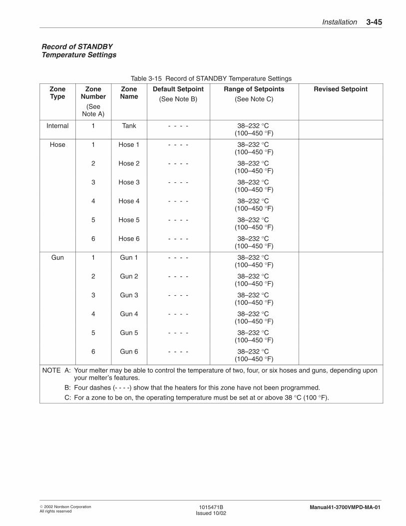
Installation 3-45
� 2002 Nordson CorporationAll rights reserved
1015471BIssued 10/02
Manual41-3700VMPD-MA-01
Table 3-15 Record of STANDBY Temperature Settings
ZoneType
ZoneNumber
(SeeNote A)
ZoneName
Default Setpoint
(See Note B)
Range of Setpoints
(See Note C)
Revised Setpoint
Internal 1 Tank - - - - 38–232 °C (100–450 °F)
Hose 1 Hose 1 - - - - 38–232 °C (100–450 °F)
2 Hose 2 - - - - 38–232 °C (100–450 °F)
3 Hose 3 - - - - 38–232 °C (100–450 °F)
4 Hose 4 - - - - 38–232 °C (100–450 °F)
5 Hose 5 - - - - 38–232 °C (100–450 °F)
6 Hose 6 - - - - 38–232 °C (100–450 °F)
Gun 1 Gun 1 - - - - 38–232 °C (100–450 °F)
2 Gun 2 - - - - 38–232 °C (100–450 °F)
3 Gun 3 - - - - 38–232 °C (100–450 °F)
4 Gun 4 - - - - 38–232 °C (100–450 °F)
5 Gun 5 - - - - 38–232 °C (100–450 °F)
6 Gun 6 - - - - 38–232 °C (100–450 °F)
NOTE A: Your melter may be able to control the temperature of two, four, or six hoses and guns, depending uponyour melter’s features.
B: Four dashes (- - - -) show that the heaters for this zone have not been programmed.
C: For a zone to be on, the operating temperature must be set at or above 38 °C (100 °F).
Record of STANDBYTemperature Settings
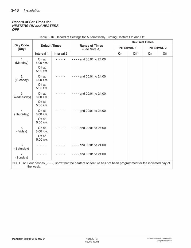
Installation3-46
� 2002 Nordson CorporationAll rights reserved
1015471BIssued 10/02
Manual41-3700VMPD-MA-01
Table 3-16 Record of Settings for Automatically Turning Heaters On and Off
Day Code Defa lt Times Range of TimesRevised Times
Day Code(Day)
Default Times Range of Times(See Note A) INTERVAL 1 INTERVAL 2(Day)
Interval 1 Interval 2(See Note A)
On Off On Off
1(Monday)
On at6:00 A.M.
Off at5:00 P.M.
- - - - - - - - and 00:01 to 24:00
2(Tuesday)
On at6:00 A.M.
Off at5:00 P.M.
- - - - - - - - and 00:01 to 24:00
3(Wednesday)
On at6:00 A.M.
Off at5:00 P.M.
- - - - - - - - and 00:01 to 24:00
4(Thursday)
On at6:00 A.M.
Off at5:00 P.M.
- - - - - - - - and 00:01 to 24:00
5(Friday)
On at6:00 A.M.
Off at5:00 P.M.
- - - - - - - - and 00:01 to 24:00
6(Saturday)
- - - - - - - - - - - - and 00:01 to 24:00
7(Sunday)
- - - - - - - - - - - - and 00:01 to 24:00
NOTE A: Four dashes (- - - -) show that the heaters on feature has not been programmed for the indicated day ofthe week.
Record of Set Times forHEATERS ON and HEATERSOFF
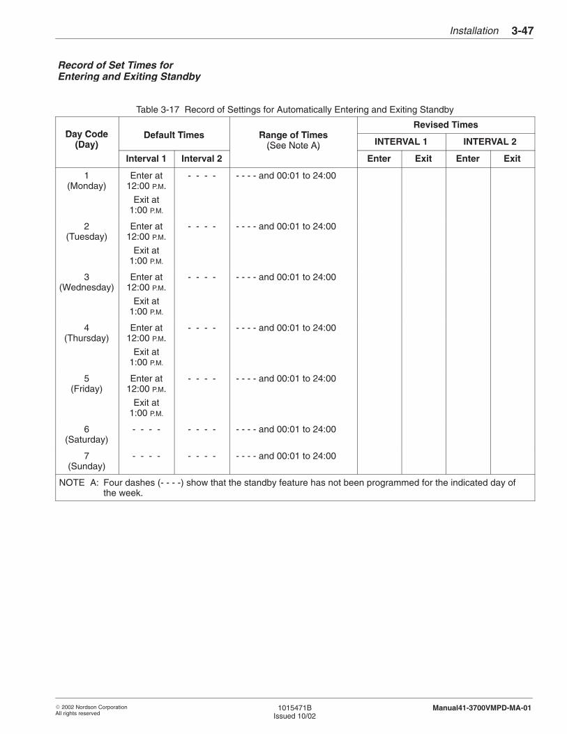
Installation 3-47
� 2002 Nordson CorporationAll rights reserved
1015471BIssued 10/02
Manual41-3700VMPD-MA-01
Table 3-17 Record of Settings for Automatically Entering and Exiting Standby
Day Code Defa lt Times Range of TimesRevised Times
Day Code(Day)
Default Times Range of Times(See Note A) INTERVAL 1 INTERVAL 2(Day)
Interval 1 Interval 2(See Note A)
Enter Exit Enter Exit
1(Monday)
Enter at12:00 P.M.
Exit at1:00 P.M.
- - - - - - - - and 00:01 to 24:00
2(Tuesday)
Enter at12:00 P.M.
Exit at1:00 P.M.
- - - - - - - - and 00:01 to 24:00
3(Wednesday)
Enter at12:00 P.M.
Exit at1:00 P.M.
- - - - - - - - and 00:01 to 24:00
4(Thursday)
Enter at12:00 P.M.
Exit at1:00 P.M.
- - - - - - - - and 00:01 to 24:00
5(Friday)
Enter at12:00 P.M.
Exit at1:00 P.M.
- - - - - - - - and 00:01 to 24:00
6(Saturday)
- - - - - - - - - - - - and 00:01 to 24:00
7(Sunday)
- - - - - - - - - - - - and 00:01 to 24:00
NOTE A: Four dashes (- - - -) show that the standby feature has not been programmed for the indicated day ofthe week.
Record of Set Times forEntering and Exiting Standby
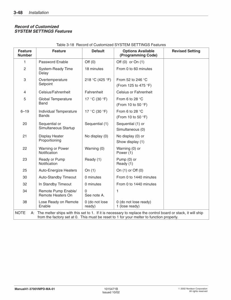
Installation3-48
� 2002 Nordson CorporationAll rights reserved
1015471BIssued 10/02
Manual41-3700VMPD-MA-01
Table 3-18 Record of Customized SYSTEM SETTINGS Features
FeatureNumber
Feature Default Options Available(Programming Code)
Revised Setting
1 Password Enable Off (0) Off (0) or On (1)
2 System-Ready TimeDelay
18 minutes From 0 to 60 minutes
3 OvertemperatureSetpoint
218 °C (425 °F) From 52 to 246 °C(From 125 to 475 °F)
4 Celsius/Fahrenheit Fahrenheit Celsius or Fahrenheit
5 Global TemperatureBand
17 �C (30 °F) From 6 to 28 °C(From 10 to 50 °F)
6–19 Individual TemperatureBands
17 �C (30 °F) From 6 to 28 °C(From 10 to 50 °F)
20 Sequential orSimultaneous Startup
Sequential (1) Sequential (1) or
Simultaneous (0)
21 Display HeaterProportioning
No display (0) No display (0) or
Show display (1)
22 Warning or PowerNotification
Warning (0) Warning (0) or Power (1)
23 Ready or PumpNotification
Ready (1) Pump (0) orReady (1)
25 Auto-Energize Heaters On (1) On (1) or Off (0)
30 Auto-Standby Timeout 0 minutes From 0 to 1440 minutes
32 In Standby Timeout 0 minutes From 0 to 1440 minutes
34 Remote Pump Enable/Remote Heaters On
0See note A.
1
38 Lose Ready on RemoteEnable
0 (do not loseready)
0 (do not lose ready)1 (lose ready)
NOTE A: The melter ships with this set to 1. If it is necessary to replace the control board or stack, it will shipfrom the factory set at 0. This must be reset to 1 for your melter to function properly.
Record of CustomizedSYSTEM SETTINGS Features
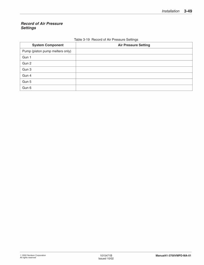
Installation 3-49
� 2002 Nordson CorporationAll rights reserved
1015471BIssued 10/02
Manual41-3700VMPD-MA-01
Table 3-19 Record of Air Pressure Settings
System Component Air Pressure Setting
Pump (piston pump melters only)
Gun 1
Gun 2
Gun 3
Gun 4
Gun 5
Gun 6
Record of Air PressureSettings
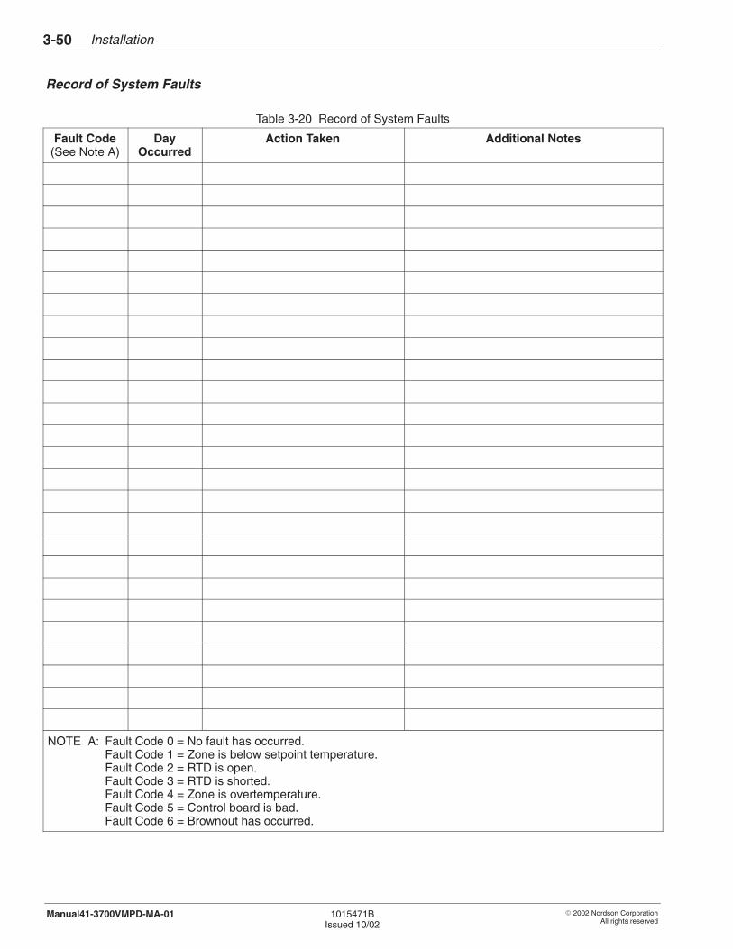
Installation3-50
� 2002 Nordson CorporationAll rights reserved
1015471BIssued 10/02
Manual41-3700VMPD-MA-01
Table 3-20 Record of System Faults
Fault Code(See Note A)
DayOccurred
Action Taken Additional Notes
NOTE A: Fault Code 0 = No fault has occurred.Fault Code 1 = Zone is below setpoint temperature.Fault Code 2 = RTD is open.Fault Code 3 = RTD is shorted.Fault Code 4 = Zone is overtemperature.Fault Code 5 = Control board is bad.Fault Code 6 = Brownout has occurred.
Record of System Faults

Installation 3-51
� 2002 Nordson CorporationAll rights reserved
1015471BIssued 10/02
Manual41-3700VMPD-MA-01
Table 3-21 Record of System Warnings
WarningCode
(See Note A)
DayOccurred Action Taken Additional Notes
NOTE A: Warning Code 0 = No warning has occurred.Warning Code 1 = Not used.Warning Code 2 = RTD is open.Warning Code 3 = RTD is shorted.Warning Code 4 = Temperature out of band.Warning Code 5 = Not used.Warning Code 6 = Not used.
Record of System Warnings

Installation3-52
� 2002 Nordson CorporationAll rights reserved
1015471BIssued 10/02
Manual41-3700VMPD-MA-01

� 2002 Nordson CorporationAll rights reserved
1015471BIssued 10/02
Manual41-3700VMPD-MA-01
Section 4
MPD

MPD4-0
� 2002 Nordson CorporationAll rights reserved
1015471BIssued 10/02
Manual41-3700VMPD-MA-01
MPD 4-1
� 2002 Nordson CorporationAll rights reserved
1015471BIssued 10/02
Manual41-3700VMPD-MA-01
Section 4MPD
The MPD unit allows the customer to run the DC motor in either AUTO orMANUAL mode. In AUTO mode, the motor and hydraulic pressure arecontrolled by the customer’s device. MANUAL mode is used fortroubleshooting and maintenance.
Installation of the MPD requires interfacing the melter with a parentmachine or pattern controller capable of providing two independent4-20 mA signals that are proportional to line speed.
Ensure that you have the following items before proceeding:
� AC Power (200–240 VAC, 3∅ 3-wire + PE, 50/60 Hz)
� I/O (Vista standard or enhanced I/O) – except the Heaters On inputcannot be used.
� MPD Board
Make the following connections:
1. 4-20 mA motor speed signal (XT3-6 [+] and XT3-5 [–]). This signalfrom the customer, OEM, or end user, controls the speed of the motorwhen running in AUTO mode. To put the unit in AUTO mode, flip therocker switch on the side panel to the right (AUTO position). TheLED on the switch should go off.
2. 4-20 mA pressure signal (XT3–8 [+] and XT3-7 [–]). This signal fromthe customer, OEM or end user controls the hydraulic pressure of thesystem when running in AUTO mode. To put the unit in AUTO mode,flip the rocker switch on the side panel to the right (AUTO position).The LED on the switch should go off.
1. Introduction
2. Installation
Making the CustomerConnections
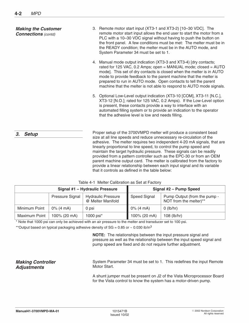
MPD4-2
� 2002 Nordson CorporationAll rights reserved
1015471BIssued 10/02
Manual41-3700VMPD-MA-01
3. Remote motor start input (XT3-1 and XT3-2) [10–30 VDC]. Theremote motor start input allows the end user to start the motor from aPLC with a 10–30 VDC signal without having to push the button onthe front panel. A few conditions must be met: The melter must be inthe READY condition; the melter must be in the AUTO mode, andSystem Parameter 34 must be set to 1.
4. Manual mode output indication (XT3-3 and XT3-4) [dry contacts;rated for 125 VAC, 0.2 Amps; open = MANUAL mode; closed = AUTOmode]. This set of dry contacts is closed when the melter is in AUTOmode to provide feedback to the parent machine that the melter isprepared to run in AUTO mode. Open contacts to tell the parentmachine that the melter is not able to respond to AUTO mode signals.
5. Optional Low-Level output indication (XT3-10 [COM], XT3-11 [N.C.],XT3-12 [N.O.]; rated for 125 VAC, 0.2 Amps). If the Low-Level optionis present, these contacts provide a way to interface with anautomated filling system or to provide an indication to the operatorthat the adhesive level is low and needs filling.
Proper setup of the 3700VMPD melter will produce a consistent beadsize at all line speeds and reduce unnecessary re-circulation of theadhesive. The melter requires two independent 4-20 mA signals, that arelinearly proportional to line speed, to control the pump speed andmaintain the target hydraulic pressure. These signals can be readilyprovided from a pattern controller such as the EPC-30 or from an OEMparent machine output card. The melter is calibrated from the factory toprovide a linear relationship between each input signal and its variablethat it controls as defined in the table below:
Table 4-1 Melter Calibration as Set at Factory
Signal #1 – Hydraulic Pressure Signal #2 – Pump Speed
Pressure Signal Hydraulic Pressure@ Melter Manifold
Speed Signal Pump Output (from the pump -NOT from the melter)**
Minimum Point 0% (4 mA) 0 psi 0% (4 mA) 0 (lb/hr)
Maximum Point 100% (20 mA) 1000 psi* 100% (20 mA) 108 (lb/hr)
* Note that 1000 psi can only be achieved with an air pressure to the melter and transducer set to 100 psi.
**Output based on typical packaging adhesive density of SG = 0.85 or ~ 0.030 ib/in3
NOTE: The relationships between the input pressure signal andpressure as well as the relationship between the input speed signal andpump speed are fixed and do not require further adjustment.
System Parameter 34 must be set to 1. This redefines the input RemoteMotor Start.
A shunt jumper must be present on J2 of the Vista Microprocessor Boardfor the Vista control to know the system has a motor-driven pump.
Making the CustomerConnections (contd)
3. Setup
Making ControllerAdjustments
MPD 4-3
� 2002 Nordson CorporationAll rights reserved
1015471BIssued 10/02
Manual41-3700VMPD-MA-01
The following is the recommended method of establishing therelationship between line speed and the necessary pressure and pumpspeed to obtain the proper size bead at the full range of line speeds.
1. Verify that the melter has been setup according to the proceduresoutlined in the Installation section of the manual.
� 100 psi air has been supplied to the melter� melter has been turned on� READY light is on
2. Using the MANUAL/AUTO switch on the side panel, place the melterin auto mode. If the pump is not already on, turn it on by pressing thepump switch on the Vista front panel.
3. Run OEM machine at minimum operational line speed.
4. Supply a 12 +/– 3 mA input signal to the motor speed input signal.
5. Supply a 4-20 mA signal to the pressure input signal until optimumsize bead is reached for your application.
6. Record this pressure input value as the minimum requirementcorresponding to the minimum line speed.
7. While still at the minimum line speed, reduce the motor speed bylowering your supplied input signal until the bead size starts todecrease (or until the manifold pressure gauge starts to decrease).
8. With this motor speed input value established, increase by ~5–20%and record this value as the minimum motor speed that correlates tothe minimum line speed.
9. Repeat steps 2 through 8 at the highest operational line speed foryour application.
10. Record the input values for maximum pressure and motor speedrequirements.
11. Use the two points for low and high speeds to establish two linearrelationships between line speed and motor speed/hydraulic pressurefor the optimum size bead.
NOTE: If using an EPC-30, this procedure is provided in its manual.
12. Establish a low limit for the pressure and motor speed.
This step is needed to obtain accurate deposition on a ramp-up fromstop.
The low limit should be ~0–10% lower than the values obtained insteps 2 through 7 above.
NOTE: If using an EPC-30, this procedure is provided in its manual.
Establishing the Bead Size
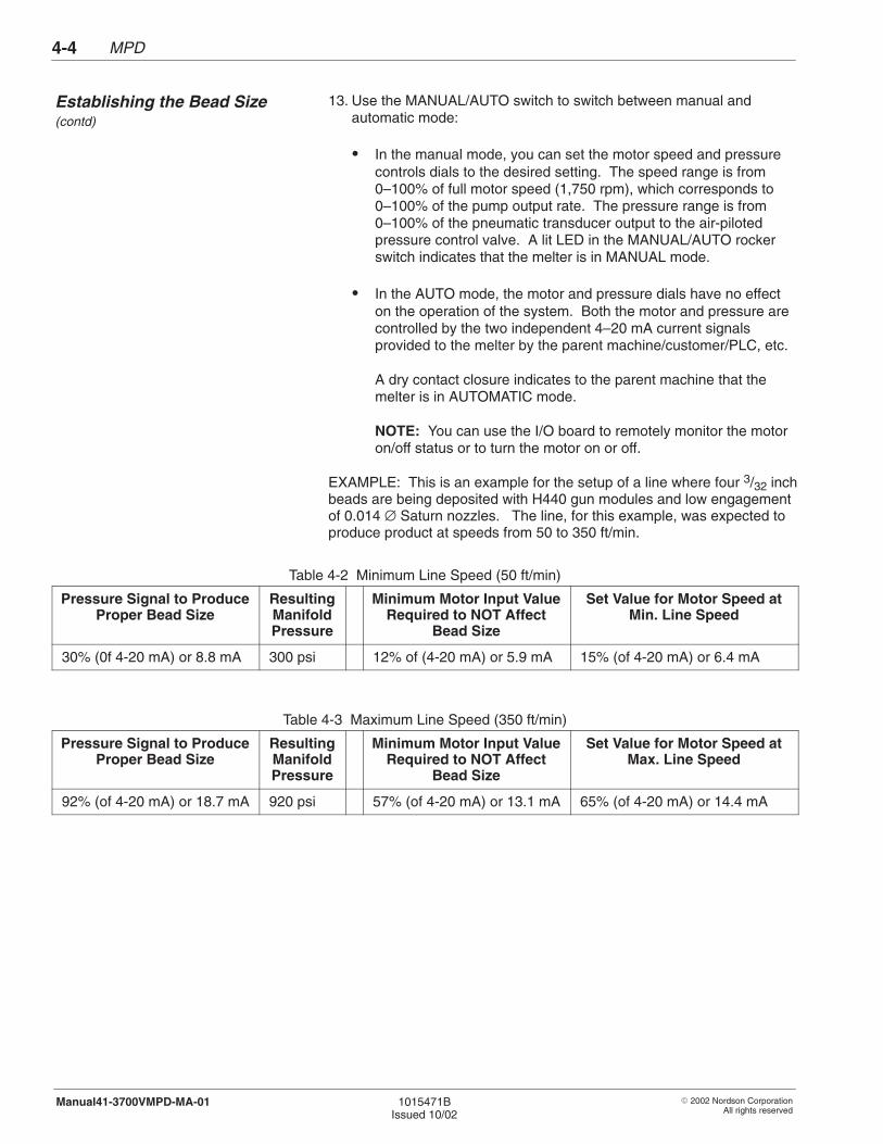
MPD4-4
� 2002 Nordson CorporationAll rights reserved
1015471BIssued 10/02
Manual41-3700VMPD-MA-01
13. Use the MANUAL/AUTO switch to switch between manual andautomatic mode:
� In the manual mode, you can set the motor speed and pressurecontrols dials to the desired setting. The speed range is from0–100% of full motor speed (1,750 rpm), which corresponds to0–100% of the pump output rate. The pressure range is from0–100% of the pneumatic transducer output to the air-pilotedpressure control valve. A lit LED in the MANUAL/AUTO rockerswitch indicates that the melter is in MANUAL mode.
� In the AUTO mode, the motor and pressure dials have no effecton the operation of the system. Both the motor and pressure arecontrolled by the two independent 4–20 mA current signalsprovided to the melter by the parent machine/customer/PLC, etc.
A dry contact closure indicates to the parent machine that themelter is in AUTOMATIC mode.
NOTE: You can use the I/O board to remotely monitor the motoron/off status or to turn the motor on or off.
EXAMPLE: This is an example for the setup of a line where four 3/32 inchbeads are being deposited with H440 gun modules and low engagementof 0.014 ∅ Saturn nozzles. The line, for this example, was expected toproduce product at speeds from 50 to 350 ft/min.
Table 4-2 Minimum Line Speed (50 ft/min)
Pressure Signal to ProduceProper Bead Size
ResultingManifoldPressure
Minimum Motor Input ValueRequired to NOT Affect
Bead Size
Set Value for Motor Speed atMin. Line Speed
30% (0f 4-20 mA) or 8.8 mA 300 psi 12% of (4-20 mA) or 5.9 mA 15% (of 4-20 mA) or 6.4 mA
Table 4-3 Maximum Line Speed (350 ft/min)
Pressure Signal to ProduceProper Bead Size
ResultingManifoldPressure
Minimum Motor Input ValueRequired to NOT Affect
Bead Size
Set Value for Motor Speed atMax. Line Speed
92% (of 4-20 mA) or 18.7 mA 920 psi 57% (of 4-20 mA) or 13.1 mA 65% (of 4-20 mA) or 14.4 mA
Establishing the Bead Size (contd)
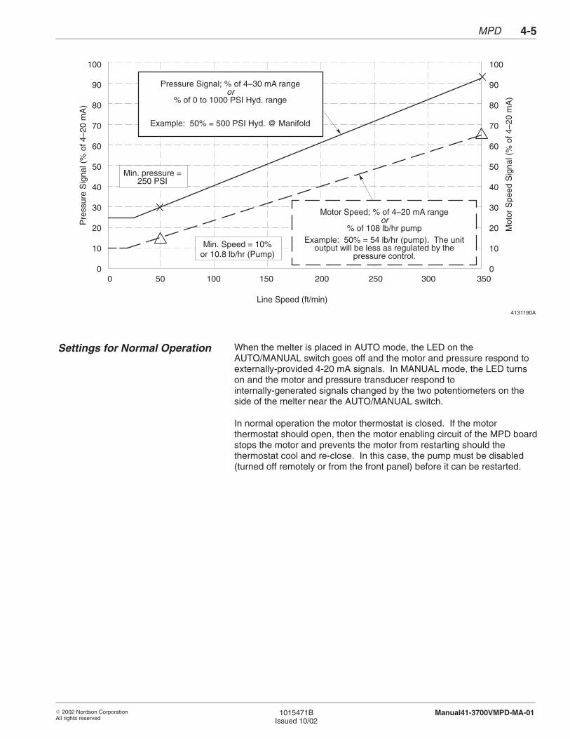
MPD 4-5
� 2002 Nordson CorporationAll rights reserved
1015471BIssued 10/02
Manual41-3700VMPD-MA-01
4131190A
100
90
80
70
60
50
40
30
20
10
0
100
90
80
70
60
50
40
30
20
10
0
Min. pressure =250 PSI
Pressure Signal; % of 4–30 mA rangeor
% of 0 to 1000 PSI Hyd. range
Example: 50% = 500 PSI Hyd. @ Manifold
Min. Speed = 10%or 10.8 lb/hr (Pump)
Motor Speed; % of 4–20 mA rangeor
% of 108 lb/hr pumpExample: 50% = 54 lb/hr (pump). The unit
output will be less as regulated by thepressure control.
Pre
ssur
e S
igna
l (%
of 4
–20
mA
)
Mot
or S
peed
Sig
nal (
% o
f 4–2
0 m
A)
Line Speed (ft/min)
0 50 100 150 200 250 300 350
When the melter is placed in AUTO mode, the LED on theAUTO/MANUAL switch goes off and the motor and pressure respond toexternally-provided 4-20 mA signals. In MANUAL mode, the LED turnson and the motor and pressure transducer respond tointernally-generated signals changed by the two potentiometers on theside of the melter near the AUTO/MANUAL switch.
In normal operation the motor thermostat is closed. If the motorthermostat should open, then the motor enabling circuit of the MPD boardstops the motor and prevents the motor from restarting should thethermostat cool and re-close. In this case, the pump must be disabled(turned off remotely or from the front panel) before it can be restarted.
Settings for Normal Operation

MPD4-6
� 2002 Nordson CorporationAll rights reserved
1015471BIssued 10/02
Manual41-3700VMPD-MA-01

� 2002 Nordson CorporationAll rights reserved
1015471BIssued 10/02
Manual41-3700VMPD-MA-01
Section 5
Operation

Operation5-0
� 2002 Nordson CorporationAll rights reserved
1015471BIssued 10/02
Manual41-3700VMPD-MA-01
Operation 5-1
� 2002 Nordson CorporationAll rights reserved
1015471BIssued 10/02
Manual41-3700VMPD-MA-01
Section 5Operation
WARNING: Allow only qualified personnel to perform thefollowing tasks. Follow the safety instructions in this documentand all other related documentation.
This section describes how to operate your melter and monitor yoursystem. Before you operate your melter, you must first program it andprepare it for first operation. Refer to System Programming Proceduresand System Preparation in the Installation section of this manual.
This part of the Operation section includes the following routine operatingprocedures:
� Turning the seven-day clock on and off� Starting the melter automatically or manually� Checking the adhesive level and filling the tank� Placing the melter in standby mode� Taking the melter out of standby mode� Shutting down the melter automatically or manually
Refer to System Monitoring Procedures in this section for procedures onchecking the zone temperatures, checking the programmed settings,checking the fault log, and running a system test.
1. Introduction
2. Operating Procedures
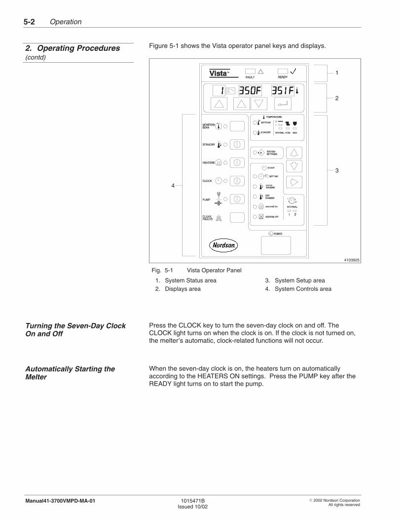
Operation5-2
� 2002 Nordson CorporationAll rights reserved
1015471BIssued 10/02
Manual41-3700VMPD-MA-01
Figure 5-1 shows the Vista operator panel keys and displays.
4103925
1
2
3
4
Fig. 5-1 Vista Operator Panel
1. System Status area2. Displays area
3. System Setup area4. System Controls area
Press the CLOCK key to turn the seven-day clock on and off. TheCLOCK light turns on when the clock is on. If the clock is not turned on,the melter’s automatic, clock-related functions will not occur.
When the seven-day clock is on, the heaters turn on automaticallyaccording to the HEATERS ON settings. Press the PUMP key after theREADY light turns on to start the pump.
2. Operating Procedures(contd)
Turning the Seven-Day ClockOn and Off
Automatically Starting theMelter
Operation 5-3
� 2002 Nordson CorporationAll rights reserved
1015471BIssued 10/02
Manual41-3700VMPD-MA-01
If you have not programmed your melter to start automatically, use thisprocedure to manually start your melter. If you have programmed yourmelter to start automatically, you will still need to start the meltermanually when you need to start the melter
� before it is time for automatic startup to occur� on a day for which the clock is turned off� because the clock was not turned on
1. If the power is off, press the POWER switch to turn the melter on.
2. If the auto-energize heaters feature is not on, press the HEATERSkey. The HEATERS light will turn on and melter will begin to heat.
3. Prepare each gun in your system for operation as follows:
� Air-operated guns: turn on the operating air.� Electric guns: turn on the gun driver.� Hand-operated guns: unlock the trigger.
4. Check the temperature setting for each heated zone.
5. When the READY light turns on, press the PUMP key. The PUMPlight will turn on and the pump will start provided that either the inputsignal is greater than 4 mA (in AUTO mode) or the motor speed dialis greater than minimum (in MANUAL mode).
The system is ready for routine operation.
Manually Starting the Melter
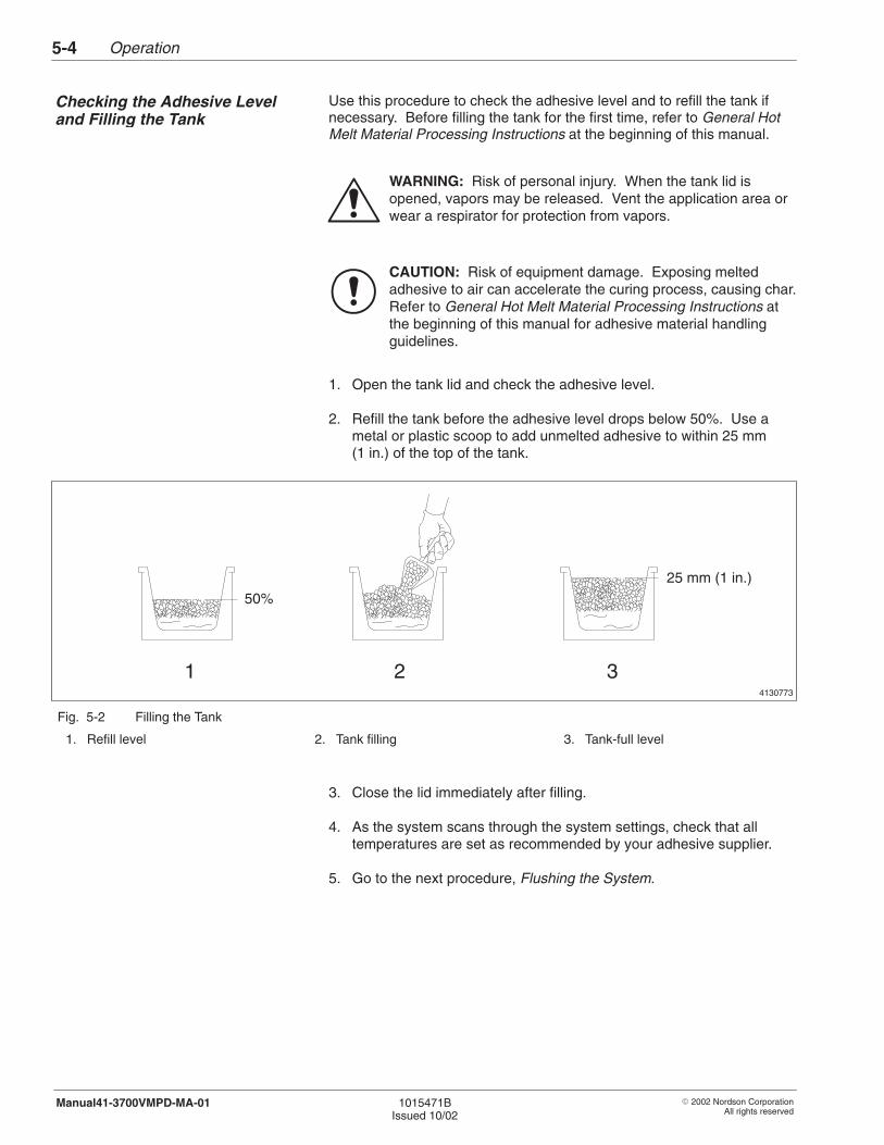
Operation5-4
� 2002 Nordson CorporationAll rights reserved
1015471BIssued 10/02
Manual41-3700VMPD-MA-01
Use this procedure to check the adhesive level and to refill the tank ifnecessary. Before filling the tank for the first time, refer to General HotMelt Material Processing Instructions at the beginning of this manual.
WARNING: Risk of personal injury. When the tank lid isopened, vapors may be released. Vent the application area orwear a respirator for protection from vapors.
CAUTION: Risk of equipment damage. Exposing meltedadhesive to air can accelerate the curing process, causing char.Refer to General Hot Melt Material Processing Instructions atthe beginning of this manual for adhesive material handlingguidelines.
1. Open the tank lid and check the adhesive level.
2. Refill the tank before the adhesive level drops below 50%. Use ametal or plastic scoop to add unmelted adhesive to within 25 mm(1 in.) of the top of the tank.
4130773
50%
25 mm (1 in.)
1 2 3
Fig. 5-2 Filling the Tank
1. Refill level 2. Tank filling 3. Tank-full level
3. Close the lid immediately after filling.
4. As the system scans through the system settings, check that alltemperatures are set as recommended by your adhesive supplier.
5. Go to the next procedure, Flushing the System.
Checking the Adhesive Leveland Filling the Tank
Operation 5-5
� 2002 Nordson CorporationAll rights reserved
1015471BIssued 10/02
Manual41-3700VMPD-MA-01
To place the melter in standby mode, press the STANDBY key. TheSTANDBY light will turn on and the READY light will turn off. The pumpwill stop and the zone temperatures will drop. The heaters will maintainheated zones at their standby temperature setpoints.
You can also program the melter to automatically enter the standby modeat a specified time. Refer to Programming CLOCK Controls in theInstallation section.
To remove the melter from standby mode, press the STANDBY key. TheSTANDBY light will turn off and the melter will heat each active zone to itsoperating temperature setpoint.
You can also program the melter to automatically exit the standby modeat a specified time. Refer to Programming CLOCK Controls in theInstallation section.
Placing the Melter In StandbyMode
Taking the Melter Out ofStandby Mode
Operation5-6
� 2002 Nordson CorporationAll rights reserved
1015471BIssued 10/02
Manual41-3700VMPD-MA-01
If the CLOCK light is on and the system is programmed to turn theheaters off automatically, the system will shut itself down.
Use this procedure to shut the melter down manually at any time.
1. Press the PUMP key. The PUMP light will turn off and the pump willstop.
2. Place a container under all guns and trigger the guns to relievesystem pressure.
3. Shut down all guns as follows:
� Air-operated guns: turn off the operating air.� Electric guns: turn off the gun driver.� Hand-operated guns: lock the trigger.
4. Turn off the pump air pressure.
5. Press the HEATERS key. The HEATERS light will turn off.
This part of the Operation section contains the following systemmonitoring procedures:
� Checking the zone temperatures� Checking the programmed settings� Checking the fault log� Running a system test
See Figure 5-1 for the Vista operator panel keys and displays.
Automatically Shutting Downthe Melter
Manually Shutting Down theMelter
3. System MonitoringProcedures
Operation 5-7
� 2002 Nordson CorporationAll rights reserved
1015471BIssued 10/02
Manual41-3700VMPD-MA-01
The Vista control system allows you to check the temperatures of allzones in sequence (to scan) or to continuously monitor the temperatureof a single zone (to monitor). When the melter is turned on, theMONITOR/SCAN light turns on and the melter scans through the heatedzones and displays the temperature of each zone sequentially.
Press the MONITOR/SCAN key to take the melter out of the scan mode.The MONITOR/SCAN light will stay on, but the melter will monitor onlythe selected zone.
NOTE: Selecting a setting in the System Setup area will take the melterout of the monitor/scan mode and the MONITOR/SCAN light will turn off.Press the MONITOR/SCAN key to return the system to monitor/scanmode. If no action is taken within two minutes, the control system willautomatically return to the monitor/scan mode.
If you did not keep a record of the programmed settings, use thisprocedure to check the settings.
1. Press the Move Up and Move Down keys until the SYSTEMSETTINGS light turns on.
2. Press the Up key below the Selector display until the feature numberfor the feature you want to check appears in the display. Refer to theSYSTEM SETTINGS Features Table in the Installation section for adescription of each feature number.
NOTE: Pressing the Move Right key allows you to move through thefeature numbers in larger increments. It will first take you to the nextlarger set of numbers (if at 14, will take you to 20), then increment by10s until it cycles back to 1.
3. Check the Multipurpose display to determine the setting for thefeature.
4. To change the setting for the feature, refer to Programming SYSTEMSETTINGS Controls in the Installation section of this manual.
Checking the ZoneTemperatures
Checking the ProgrammedSYSTEM SETTINGS Features

Operation5-8
� 2002 Nordson CorporationAll rights reserved
1015471BIssued 10/02
Manual41-3700VMPD-MA-01
Use this procedure to check the warning or fault log. These logs list thecauses of the three most recent warnings or faults. The actualtemperature display shows the length of time the heaters have been onwhen the warning/fault occured.
1. Press the Move Up and Move Down keys until the SYSTEMSETTINGS light turns on.
2. Press the Up key below the Selector display until the feature numberof the warning or fault you want to check appears in the display.Refer to Table 5-1 or 5-2.
NOTE: Pressing the Move Right key allows you to move through thefeature numbers in larger increments. It will first take you to the nextlarger set of numbers (if at 14, will take you to 20), then increment by10s until it cycles back to 1.
Table 5-1 Warning Log Feature Numbers
Feature No. Warning Displayed
35 The zone number and warning code for themost recent warning will be displayed in theMultipurpose display.
36 The zone number and warning code for thesecond most recent warning will bedisplayed in the Multipurpose display.
37 The zone number and warning code for thethird most recent warning will be displayedin the Multipurpose display.
Table 5-2 Fault Log Feature Numbers
Feature No. Fault Displayed
27 The zone number and fault code for themost recent fault will be displayed in theMultipurpose display.
28 The zone number and fault code for thesecond most recent fault will be displayedin the Multipurpose display.
29 The zone number and fault code for thethird most recent fault will be displayed inthe Multipurpose display.
Checking the Warning or FaultLog
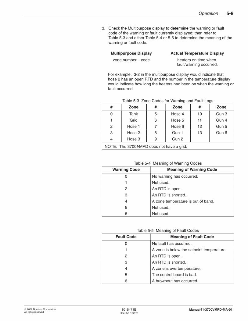
Operation 5-9
� 2002 Nordson CorporationAll rights reserved
1015471BIssued 10/02
Manual41-3700VMPD-MA-01
3. Check the Multipurpose display to determine the warning or faultcode of the warning or fault currently displayed; then refer toTable 5-3 and either Table 5-4 or 5-5 to determine the meaning of thewarning or fault code.
Multipurpose Display Actual Temperature Display
zone number – code heaters on time when fault/warning occurred.
For example, 3-2 in the multipurpose display would indicate thathose 2 has an open RTD and the number in the temperature displaywould indicate how long the heaters had been on when the warning orfault occurred.
Table 5-3 Zone Codes for Warning and Fault Logs
# Zone # Zone # Zone
0 Tank 5 Hose 4 10 Gun 3
1 Grid 6 Hose 5 11 Gun 4
2 Hose 1 7 Hose 6 12 Gun 5
3 Hose 2 8 Gun 1 13 Gun 6
4 Hose 3 9 Gun 2
NOTE: The 3700VMPD does not have a grid.
Table 5-4 Meaning of Warning Codes
Warning Code Meaning of Warning Code
0 No warning has occurred.
1 Not used.
2 An RTD is open.
3 An RTD is shorted.
4 A zone temperature is out of band.
5 Not used.
6 Not used.
Table 5-5 Meaning of Fault Codes
Fault Code Meaning of Fault Code
0 No fault has occurred.
1 A zone is below the setpoint temperature.
2 An RTD is open.
3 An RTD is shorted.
4 A zone is overtemperature.
5 The control board is bad.
6 A brownout has occurred.
Operation5-10
� 2002 Nordson CorporationAll rights reserved
1015471BIssued 10/02
Manual41-3700VMPD-MA-01
NOTE: Refer to the following sections of this manual for additionaltroubleshooting and repair information:
� The Hydraulics section contains troubleshooting and repairprocedures for the pump and manifold assemblies.
� The Control section contains troubleshooting and repairprocedures for system board and heating zone problems.
4. To clear the warning log, press the CLEAR FAULTS key.
After you have corrected a problem that caused the melter to register afault, press the CLEAR FAULTS key to run a system test. During thefive-second test, the following occur:
� All lights on the operator panel turn on.� Information in the Displays area changes.
Problem corrected? Result:
Yes The FAULT light turns off when the test iscomplete and the system will enter themonitor/scan mode.
No The FAULT light stays on when the test iscomplete. Refer to Checking the Fault Login this section.
Contact your material supplier about the compatibility of the old and newmaterials. If the old and new adhesives are compatible, add the newadhesive to the tank. If the new adhesive is not compatible with the oldone, ask your supplier for an acceptable flushing material to thoroughlyclean the system.
Use this procedure to clean the system before changing to an adhesivethat is incompatible with the old one.
1. Ensure that the melter is at operating temperature.
WARNING: System or material pressurized. Relieve systempressure. Failure to observe may result in serious burns.
2. Relieve system pressure. Refer to Relieving System Pressure in theMaintenance section.
3. Drain the melter by pumping as much adhesive from the tank aspossible using one of the following methods.
Checking the Warning or FaultLog (contd)
Running a System Test
4. Procedure for ChangingAdhesives
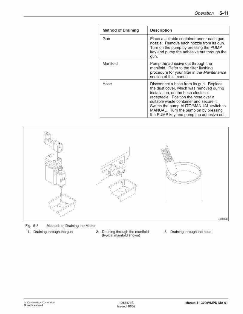
Operation 5-11
� 2002 Nordson CorporationAll rights reserved
1015471BIssued 10/02
Manual41-3700VMPD-MA-01
Method of Draining Description
Gun Place a suitable container under each gunnozzle. Remove each nozzle from its gun.Turn on the pump by pressing the PUMPkey and pump the adhesive out through thegun.
Manifold Pump the adhesive out through themanifold. Refer to the filter flushingprocedure for your filter in the Maintenancesection of this manual.
Hose Disconnect a hose from its gun. Replacethe dust cover, which was removed duringinstallation, on the hose electricalreceptacle. Position the hose over asuitable waste container and secure it.Switch the pump AUTO/MANUAL switch toMANUAL. Turn the pump on by pressingthe PUMP key and pump the adhesive out.
4103998
Fig. 5-3 Methods of Draining the Melter
1. Draining through the gun 2. Draining through the manifold(typical manifold shown)
3. Draining through the hose

Operation5-12
� 2002 Nordson CorporationAll rights reserved
1015471BIssued 10/02
Manual41-3700VMPD-MA-01
4. If you have not already done so, disconnect each hose in the systemfrom its gun.
5. Clean each automatic gun and hand-operated gun as needed. Referto the gun manual for information on gun disassembly, cleaning, andrebuilding.
6. Flush the system with the flushing material recommended by youradhesive supplier. Refer to the procedure To Flush the System with aFlushing Material or the procedure To Flush the System with Type RFluid in the Maintenance section of this manual.
7. Check the Material Safety Data Sheet (MSDS) for the recommendedoperating temperature of the new adhesive. If the temperature isdifferent from the old adhesive, reprogram your melter’s temperaturesettings. Refer to Table 5-6.
Table 5-6 Temperature Programming Procedures
Type of Temperature Setting Programming Procedure
Overtemperature setpoint Refer to Programming SYSTEMSETTINGS Controls in theInstallation section of this manual.
SETPOINT or STANDBYtemperature setpoint
Refer to ProgrammingTEMPERATURE Controls in theInstallation section of this manual.
The melter is ready for routine operation. Refer to Operating Proceduresin this section.
4. Procedure for ChangingAdhesives (contd)
� 2002 Nordson CorporationAll rights reserved
1015471BIssued 10/02
Manual41-3700VMPD-MA-01
Section 6
Maintenance

Maintenance6-0
� 2002 Nordson CorporationAll rights reserved
1015471BIssued 10/02
Manual41-3700VMPD-MA-01
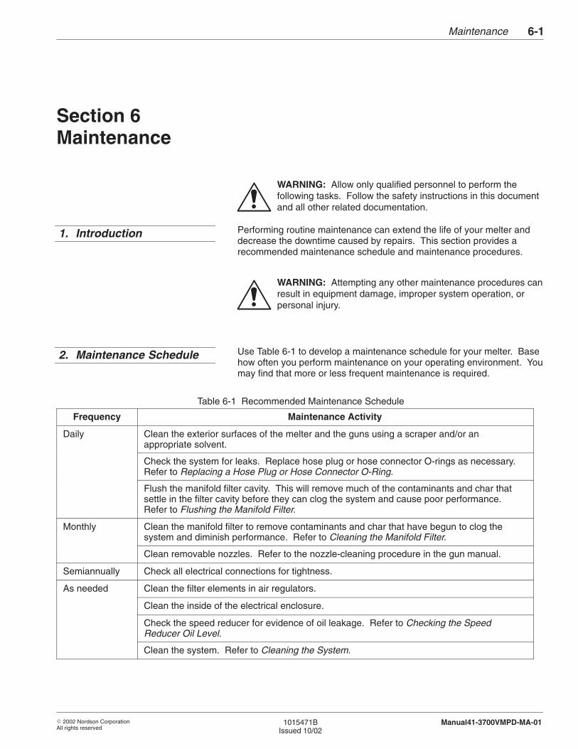
Maintenance 6-1
� 2002 Nordson CorporationAll rights reserved
1015471BIssued 10/02
Manual41-3700VMPD-MA-01
Section 6Maintenance
WARNING: Allow only qualified personnel to perform thefollowing tasks. Follow the safety instructions in this documentand all other related documentation.
Performing routine maintenance can extend the life of your melter anddecrease the downtime caused by repairs. This section provides arecommended maintenance schedule and maintenance procedures.
WARNING: Attempting any other maintenance procedures canresult in equipment damage, improper system operation, orpersonal injury.
Use Table 6-1 to develop a maintenance schedule for your melter. Basehow often you perform maintenance on your operating environment. Youmay find that more or less frequent maintenance is required.
Table 6-1 Recommended Maintenance Schedule
Frequency Maintenance Activity
Daily Clean the exterior surfaces of the melter and the guns using a scraper and/or anappropriate solvent.
Check the system for leaks. Replace hose plug or hose connector O-rings as necessary.Refer to Replacing a Hose Plug or Hose Connector O-Ring.
Flush the manifold filter cavity. This will remove much of the contaminants and char thatsettle in the filter cavity before they can clog the system and cause poor performance.Refer to Flushing the Manifold Filter.
Monthly Clean the manifold filter to remove contaminants and char that have begun to clog thesystem and diminish performance. Refer to Cleaning the Manifold Filter.
Clean removable nozzles. Refer to the nozzle-cleaning procedure in the gun manual.
Semiannually Check all electrical connections for tightness.
As needed Clean the filter elements in air regulators.
Clean the inside of the electrical enclosure.
Check the speed reducer for evidence of oil leakage. Refer to Checking the SpeedReducer Oil Level.
Clean the system. Refer to Cleaning the System.
1. Introduction
2. Maintenance Schedule
Maintenance6-2
� 2002 Nordson CorporationAll rights reserved
1015471BIssued 10/02
Manual41-3700VMPD-MA-01
Use the following maintenance procedures as appropriate for youroperation. Table 6-1 provides a recommended maintenance schedule.
Hydraulic pressure must be relieved before you can safely proceed withmany of the maintenance, troubleshooting, and repair procedures in thismanual. Follow this procedure whenever you are instructed to relievehydraulic pressure.
1. Make sure the melter is at operating temperature.
2. Turn the pump motor off and set the motor speed control dial fullycounterclockwise; then place the MANUAL/AUTO switch in theMANUAL position.
3. Place a container under all guns and under the manifold drain valve.
4. Trigger one or more guns until adhesive stops flowing.
5. With the filter in the RUN position, open the right-side manifold drainvalve.
6. Allow some adhesive to drain from the manifold.
7. Close the drain valve.
3. Maintenance Procedures
Relieving Hydraulic Pressure
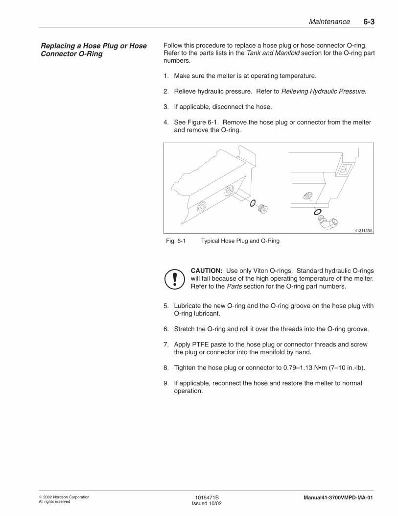
Maintenance 6-3
� 2002 Nordson CorporationAll rights reserved
1015471BIssued 10/02
Manual41-3700VMPD-MA-01
Follow this procedure to replace a hose plug or hose connector O-ring.Refer to the parts lists in the Tank and Manifold section for the O-ring partnumbers.
1. Make sure the melter is at operating temperature.
2. Relieve hydraulic pressure. Refer to Relieving Hydraulic Pressure.
3. If applicable, disconnect the hose.
4. See Figure 6-1. Remove the hose plug or connector from the melterand remove the O-ring.
4131123A
Fig. 6-1 Typical Hose Plug and O-Ring
CAUTION: Use only Viton O-rings. Standard hydraulic O-ringswill fail because of the high operating temperature of the melter.Refer to the Parts section for the O-ring part numbers.
5. Lubricate the new O-ring and the O-ring groove on the hose plug withO-ring lubricant.
6. Stretch the O-ring and roll it over the threads into the O-ring groove.
7. Apply PTFE paste to the hose plug or connector threads and screwthe plug or connector into the manifold by hand.
8. Tighten the hose plug or connector to 0.79–1.13 N�m (7–10 in.-lb).
9. If applicable, reconnect the hose and restore the melter to normaloperation.
Replacing a Hose Plug or HoseConnector O-Ring

Maintenance6-4
� 2002 Nordson CorporationAll rights reserved
1015471BIssued 10/02
Manual41-3700VMPD-MA-01
Use these procedures to periodically clean the system. System cleaningremoves dirt and char that clog the system and cause poor systemperformance. You should also clean the system if you switch to a newtype of adhesive that is incompatible with the old adhesive. If you are notsure whether the adhesives are compatible, contact your adhesivesupplier.
Drain the Tank
Before the system can be cleaned, you must drain the tank. This can beaccomplished by running the system until all the adhesive is consumedor by pumping the adhesive out as waste. The tank can be drainedthrough a gun, a hose, or the filter cavity and drain valve. Follow thisprocedure to drain the tank.
1. Turn the pump motor off and set the motor speed and pump pressurecontrol dials fully counterclockwise; then place the MANUAL/AUTOswitch in the MANUAL position.
2. Open the drain valve to relieve hydraulic pressure (on reverse-flushfilter melters, open the right-side drain valve).
3. Follow these steps to pump the adhesive out through a gun:
a. Remove the gun nozzle.
b. Place a waste container under the gun.
c. Trigger the gun and hold it open; then close the drain valve.
d. Turn pump motor on and turn the motor speed dial clockwise.
e. Pump adhesive out.
f. Turn off and set motor speed dial fully counterclockwise.
4. Follow these steps to pump the adhesive out through a hose:
a. Set the gun temperature setpoint to 0.
b. Disconnect the hose from the gun and secure the hose over awaste container.
c. Close the drain valve.
d. Turn pump motor on and turn the motor speed dial clockwise.
e. Pump adhesive out.
f. Turn off and set motor speed dial fully counterclockwise.
Cleaning the System
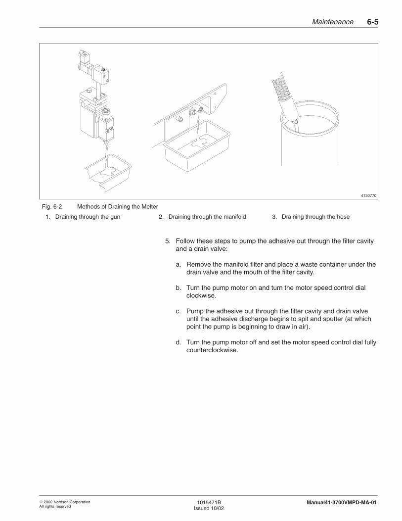
Maintenance 6-5
� 2002 Nordson CorporationAll rights reserved
1015471BIssued 10/02
Manual41-3700VMPD-MA-01
4130770
Fig. 6-2 Methods of Draining the Melter
1. Draining through the gun 2. Draining through the manifold 3. Draining through the hose
5. Follow these steps to pump the adhesive out through the filter cavityand a drain valve:
a. Remove the manifold filter and place a waste container under thedrain valve and the mouth of the filter cavity.
b. Turn the pump motor on and turn the motor speed control dialclockwise.
c. Pump the adhesive out through the filter cavity and drain valveuntil the adhesive discharge begins to spit and sputter (at whichpoint the pump is beginning to draw in air).
d. Turn the pump motor off and set the motor speed control dial fullycounterclockwise.
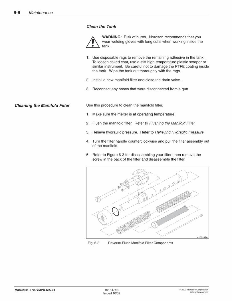
Maintenance6-6
� 2002 Nordson CorporationAll rights reserved
1015471BIssued 10/02
Manual41-3700VMPD-MA-01
Clean the Tank
WARNING: Risk of burns. Nordson recommends that youwear welding gloves with long cuffs when working inside thetank.
1. Use disposable rags to remove the remaining adhesive in the tank.To loosen caked char, use a stiff high-temperature plastic scraper orsimilar instrument. Be careful not to damage the PTFE coating insidethe tank. Wipe the tank out thoroughly with the rags.
2. Install a new manifold filter and close the drain valve.
3. Reconnect any hoses that were disconnected from a gun.
Use this procedure to clean the manifold filter.
1. Make sure the melter is at operating temperature.
2. Flush the manifold filter. Refer to Flushing the Manifold Filter.
3. Relieve hydraulic pressure. Refer to Relieving Hydraulic Pressure.
4. Turn the filter handle counterclockwise and pull the filter assembly outof the manifold.
5. Refer to Figure 6-3 for disassembling your filter; then remove thescrew in the back of the filter and disassemble the filter.
4103288A
Fig. 6-3 Reverse-Flush Manifold Filter Components
Cleaning the Manifold Filter
Maintenance 6-7
� 2002 Nordson CorporationAll rights reserved
1015471BIssued 10/02
Manual41-3700VMPD-MA-01
WARNING: Risk of fire or explosion. Do not heat NordsonType-R cleaning fluid above 246 °C (475 °F). Do not heatcleaning fluid with an open flame or in an unregulated heatingdevice.
6. Use one of the following methods to heat the filter components:
� Place the filter components, except for the O-ring, in a containerof Type-R cleaning fluid and heat the fluid above the melting pointof the adhesive.
� Use a flameless heat gun to heat the filter components.
CAUTION: If you use a stiff metal brush to clean the filterscreen, be careful not to damage the screen. Damage to thescreen mesh will diminish the effectiveness of the filter.
7. Scrub the filter components with a fine-bristled brush. Be sure toscrub the filter screen both inside and out.
8. Wipe the components with a clean, dry cloth.
9. Inspect the filter screen and O-ring for damage and replace ifnecessary. A dent or break in the filter screen mesh means that thescreen is damaged beyond repair and should be replaced. Refer tothe Parts section for replacement component part numbers.
10. See Figure 6-3. Reassemble the filter.
CAUTION: Risk of equipment damage. The melter must be atoperating temperature before the filter is resinstalled. Coldadhesive in the manifold cavity will prevent insertion of the filterassembly.
11. Make sure the melter is at operating temperature.
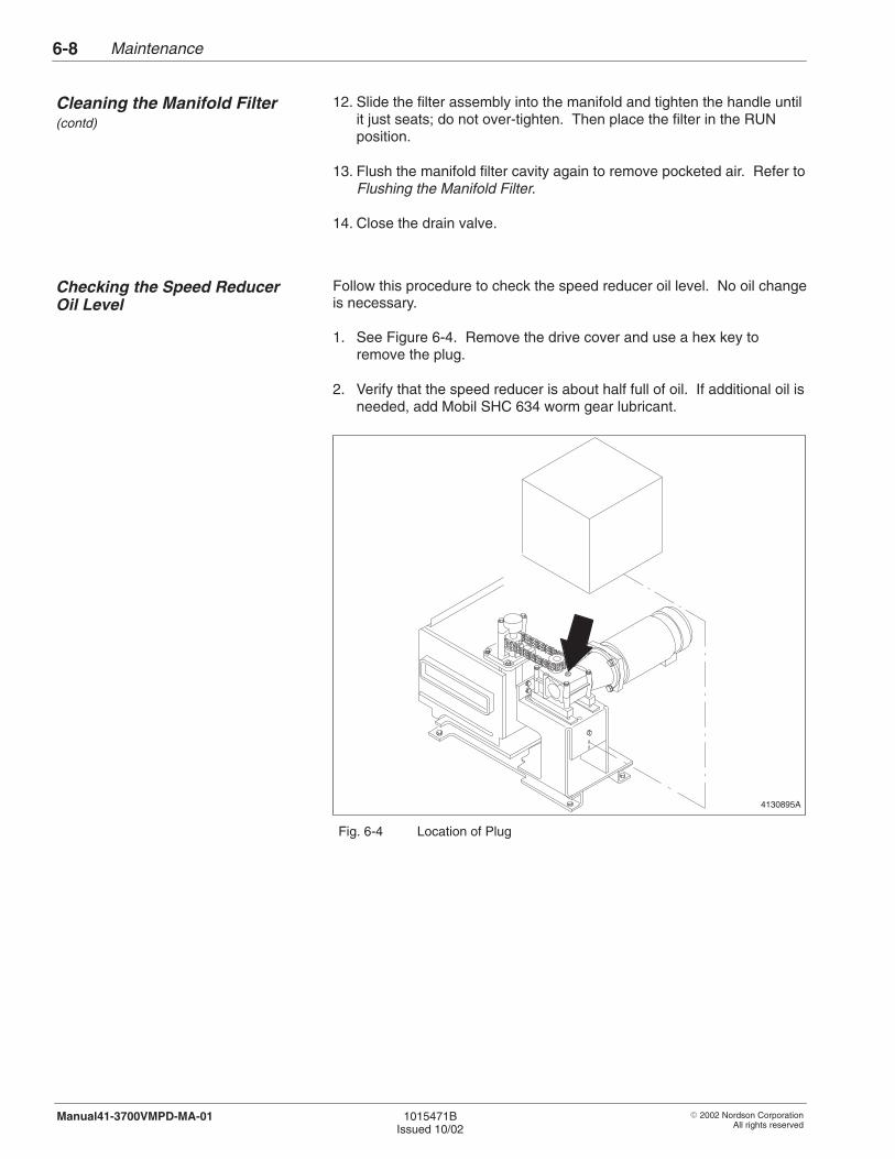
Maintenance6-8
� 2002 Nordson CorporationAll rights reserved
1015471BIssued 10/02
Manual41-3700VMPD-MA-01
12. Slide the filter assembly into the manifold and tighten the handle untilit just seats; do not over-tighten. Then place the filter in the RUNposition.
13. Flush the manifold filter cavity again to remove pocketed air. Refer toFlushing the Manifold Filter.
14. Close the drain valve.
Follow this procedure to check the speed reducer oil level. No oil changeis necessary.
1. See Figure 6-4. Remove the drive cover and use a hex key toremove the plug.
2. Verify that the speed reducer is about half full of oil. If additional oil isneeded, add Mobil SHC 634 worm gear lubricant.
4130895A
Fig. 6-4 Location of Plug
Cleaning the Manifold Filter (contd)
Checking the Speed ReducerOil Level
Maintenance 6-9
� 2002 Nordson CorporationAll rights reserved
1015471BIssued 10/02
Manual41-3700VMPD-MA-01
Before operating your melter for the first time, use these procedures toflush the system with adhesive to remove trapped air and residue leftfrom factory testing. Before proceeding with this procedure, complete theprocedures in Melter Installation, Hose and Gun Installation, ElectricalInstallation, and Air Supply Installation in the Installation section.
Follow this procedure to start up the melter for the first time in preparationfor system flushing.
1. Turn the AUTO/MANUAL switch to manual. A lit LED in the switchindicates that the melter is in MANUAL mode.
NOTE: If the melter is not turned on, the LED will not light.
2. If melter is not already on, press the POWER switch to turn the melteron. Allow the melter to reach operating temperature.
3. Fill the tank or hopper with fresh, clean adhesive to within25 mm (1 in.) of the top of the tank and close the lid.
4. If pump is not already off, press the PUMP switch to turn thepump off.
WARNING: Risk of personal injury or equipment damage. Donot heat adhesives above the recommended operatingtemperature. Doing so can generate dangerous vapors andcause charring.
5. Set all the temperatures zones (hoses, guns, or tank) to the desiredoperating temperature setpoints. Consult the adhesive supplier’smaterial safety data sheet for recommended temperature setpoints.
WARNING: Hot! Risk of burns. Wear heat-protective clothing,safety goggles, and heat-protective gloves.
6. Use the following methods to prevent accidental gun triggering:
� Air-operated guns: turn off the operating air.� Electric guns: turn off the gun driver.� Hand-operated guns: lock the trigger.
7. Remove the nozzles from all guns.
4. Flushing the System
Preparing to Flush the System
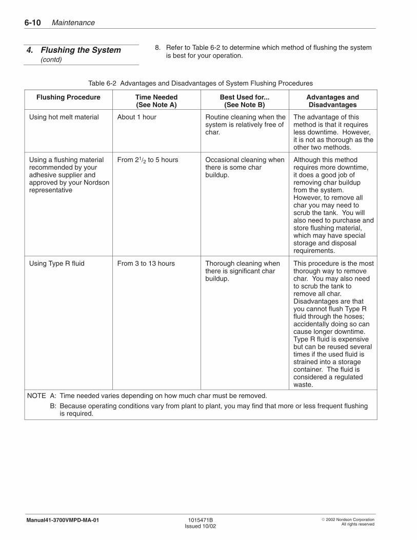
Maintenance6-10
� 2002 Nordson CorporationAll rights reserved
1015471BIssued 10/02
Manual41-3700VMPD-MA-01
8. Refer to Table 6-2 to determine which method of flushing the systemis best for your operation.
Table 6-2 Advantages and Disadvantages of System Flushing Procedures
Flushing Procedure Time Needed(See Note A)
Best Used for...(See Note B)
Advantages andDisadvantages
Using hot melt material About 1 hour Routine cleaning when thesystem is relatively free ofchar.
The advantage of thismethod is that it requiresless downtime. However,it is not as thorough as theother two methods.
Using a flushing materialrecommended by youradhesive supplier andapproved by your Nordsonrepresentative
From 21/2 to 5 hours Occasional cleaning whenthere is some charbuildup.
Although this methodrequires more downtime,it does a good job ofremoving char buildupfrom the system.However, to remove allchar you may need toscrub the tank. You willalso need to purchase andstore flushing material,which may have specialstorage and disposalrequirements.
Using Type R fluid From 3 to 13 hours Thorough cleaning whenthere is significant charbuildup.
This procedure is the mostthorough way to removechar. You may also needto scrub the tank toremove all char.Disadvantages are thatyou cannot flush Type Rfluid through the hoses;accidentally doing so cancause longer downtime.Type R fluid is expensivebut can be reused severaltimes if the used fluid isstrained into a storagecontainer. The fluid isconsidered a regulatedwaste.
NOTE A: Time needed varies depending on how much char must be removed.
B: Because operating conditions vary from plant to plant, you may find that more or less frequent flushingis required.
4. Flushing the System(contd)
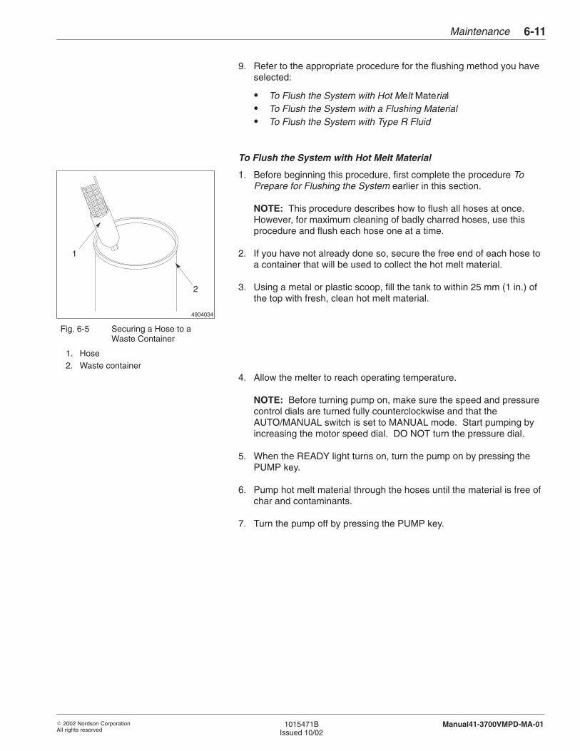
4904034
1
2
Maintenance 6-11
� 2002 Nordson CorporationAll rights reserved
1015471BIssued 10/02
Manual41-3700VMPD-MA-01
9. Refer to the appropriate procedure for the flushing method you haveselected:
� To Flush the System with Hot Melt Material� To Flush the System with a Flushing Material� To Flush the System with Type R Fluid
To Flush the System with Hot Melt Material
1. Before beginning this procedure, first complete the procedure ToPrepare for Flushing the System earlier in this section.
NOTE: This procedure describes how to flush all hoses at once.However, for maximum cleaning of badly charred hoses, use thisprocedure and flush each hose one at a time.
2. If you have not already done so, secure the free end of each hose toa container that will be used to collect the hot melt material.
3. Using a metal or plastic scoop, fill the tank to within 25 mm (1 in.) ofthe top with fresh, clean hot melt material.
Fig. 6-5 Securing a Hose to aWaste Container
1. Hose2. Waste container
4. Allow the melter to reach operating temperature.
NOTE: Before turning pump on, make sure the speed and pressurecontrol dials are turned fully counterclockwise and that theAUTO/MANUAL switch is set to MANUAL mode. Start pumping byincreasing the motor speed dial. DO NOT turn the pressure dial.
5. When the READY light turns on, turn the pump on by pressing thePUMP key.
6. Pump hot melt material through the hoses until the material is free ofchar and contaminants.
7. Turn the pump off by pressing the PUMP key.
Maintenance6-12
� 2002 Nordson CorporationAll rights reserved
1015471BIssued 10/02
Manual41-3700VMPD-MA-01
To Flush the System with Hot Melt Material (contd)
CAUTION: Using a metal brush or scraper can damagePTFE-coated tanks. Use a stiff-bristled, nonmetal brush whencleaning a PTFE-coated tank.
8. Use a stiff-bristled, non-metal brush or similar tool to scrub the tank ordislodge as much char and debris as possible. Do not use a metalbrush or scraper on PTFE-coated tanks.
NOTE: If this procedure does not remove all the charred material,you may need to replace the tank. Refer to the procedure forreplacing the tank in the Tank section of this manual.
9. Clean the manifold filter. Refer to Cleaning the Manifold Filter.
10. Go to the procedure To Restore the Melter to Normal Operation.
To Flush the System with a Flushing Material
WARNING: Use the flushing material at the manufacturer’srecommended temperature, which will be below the hot meltmaterial’s flash point. Failure to observe this warning cancause a fire.
WARNING: Never flush your system or clean any aluminumcomponents with halogenated hydrocarbon cleaning solutions.These cleaning solutions are extremely dangerous when usedto clean aluminum components in a pressurized fluid system.
CAUTION: Do not use this procedure to flush your system withType R fluid. This procedure instructs you to pump flushingmaterial through the hoses. Flushing Type R fluid throughhoses can cause large pieces of char to break off and clog thenozzles during later operation. If you plan to use Type R fluid toflush your system, refer the procedure To Flush the System withType R Fluid in this section.
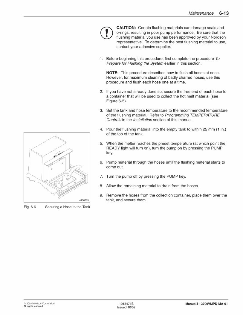
4130769
Maintenance 6-13
� 2002 Nordson CorporationAll rights reserved
1015471BIssued 10/02
Manual41-3700VMPD-MA-01
CAUTION: Certain flushing materials can damage seals ando-rings, resulting in poor pump performance. Be sure that theflushing material you use has been approved by your Nordsonrepresentative. To determine the best flushing material to use,contact your adhesive supplier.
1. Before beginning this procedure, first complete the procedure ToPrepare for Flushing the System earlier in this section.
NOTE: This procedure describes how to flush all hoses at once.However, for maximum cleaning of badly charred hoses, use thisprocedure and flush each hose one at a time.
2. If you have not already done so, secure the free end of each hose toa container that will be used to collect the hot melt material (seeFigure 6-5).
3. Set the tank and hose temperature to the recommended temperatureof the flushing material. Refer to Programming TEMPERATUREControls in the Installation section of this manual.
4. Pour the flushing material into the empty tank to within 25 mm (1 in.)of the top of the tank.
5. When the melter reaches the preset temperature (at which point theREADY light will turn on), turn the pump on by pressing the PUMPkey.
6. Pump material through the hoses until the flushing material starts tocome out.
7. Turn the pump off by pressing the PUMP key.
8. Allow the remaining material to drain from the hoses.
9. Remove the hoses from the collection container, place them over thetank, and secure them.
Fig. 6-6 Securing a Hose to the Tank
Maintenance6-14
� 2002 Nordson CorporationAll rights reserved
1015471BIssued 10/02
Manual41-3700VMPD-MA-01
To Flush the System with a Flushing Material (contd)
NOTE: Before turning pump on, make sure the speed and pressurecontrol dials are turned fully counterclockwise and that theAUTO/MANUAL switch is set to MANUAL mode. Start pumping byincreasing the motor speed dial. DO NOT turn the pressure dial.
10. Turn the pump on by pressing the PUMP key.
11. Allow the flushing material to circulate through the system for 11/2 to 4hours.
12. Turn the pump off by pressing the PUMP key.
13. Wait for any remaining material to drain from the hoses.
14. Remove the hoses from the tank, secure them over a waste container(see Figure 6-5), and drain the flushing material from the tank into thecontainer.
CAUTION: Using a metal brush or scraper can damagePTFE-coated tanks. Use a stiff-bristled, nonmetal brush whencleaning a PTFE-coated tank.
15. Use a stiff-bristled, nonmetal brush or similar tool to scrub the tank ordislodge as much char and debris as possible. Do not use a metalbrush or scraper on PTFE-coated tanks.
NOTE: If this procedure does not remove all the charred material,you may need to replace the tank. Refer to the procedure forreplacing the tank in the Tank section of this manual.
16. Using a metal or plastic scoop, fill the tank to within 25 mm (1 in.) ofthe top with fresh, clean hot melt material.
17. Set the temperature of the tank to the lowest temperature that theadhesive can be pumped at. Refer to Programming TEMPERATUREControls in the Installation section of this manual.
18. Wait for the melter to reach the preset temperature, then drain 3/4 ofthe adhesive through the hoses into the waste container.
19. After you have drained 3/4 of the material, turn the pump off bypressing the PUMP key.
Maintenance 6-15
� 2002 Nordson CorporationAll rights reserved
1015471BIssued 10/02
Manual41-3700VMPD-MA-01
20. Place a container under the manifold drain valve, open the valve, anddrain the remaining adhesive (see Figure 6-2).
21. Clean the manifold filter. Refer to Cleaning a Manifold Filter in thissection.
22. Go to the procedure To Restore the Melter to Normal Operation inthis section.
To Flush the System with Type R Fluid
1. Before beginning this procedure, first complete the procedure ToPrepare for Flushing the System earlier in this section.
2. Set the tank temperature 14–17 °C (25–30 °F) higher than therecommended application temperature of the adhesive. Refer toProgramming TEMPERATURE Controls in the Installation section ofthis manual.
3. Pour Type R fluid into the empty tank to within 25 mm (1 in.) of thetop of the tank.
4. Use a clean paint brush or similar tool to apply fluid to areas notsubmerged in the fluid.
5. Allow the fluid to heat in the tank for 2–12 hours.
6. As needed, use a wooden or plastic strainer to skim off the char andadhesive that floats to the top of the tank.
CAUTION: Do not pump Type R fluid through hoses. Fluidabsorbed by char in the hoses may leach out or cause largepieces of char to break off and clog a nozzle during lateroperation.
7. Place a container under the manifold drain valve, open the valve, anddrain the fluid from the manifold (see Figure 6-7).
NOTE: You can reuse the fluid if you place a strainer on the top ofthe container used to collect it.
Maintenance6-16
� 2002 Nordson CorporationAll rights reserved
1015471BIssued 10/02
Manual41-3700VMPD-MA-01
To Flush the System with Type R Fluid (contd)
8. Close the manifold drain valve.
9. Using a metal or plastic scoop, place several pounds of fresh, cleanhot melt material into the empty tank.
10. Set the temperature of the tank and hoses to the lowest temperaturethat the adhesive can be pumped at. Refer to ProgrammingTEMPERATURE Controls in the Installation section of this manual.
11. Secure the free end of the hose to a container that will be used tocollect the hot melt material (see Figure 6-5).
NOTE: Before turning pump on, make sure the speed and pressurecontrol dials are turned fully counterclockwise and that theAUTO/MANUAL switch is set to MANUAL mode. Start pumping byincreasing the motor speed dial. DO NOT turn the pressure dial.
12. When the tank and hoses reach their setpoint temperatures (at whichpoint the READY light will turn on), turn the pump on by pressing thePUMP key.
13. Pump adhesive into the containers until a clean, steady stream ofmaterial flows from each hose.
14. When material has finished draining, turn the pump off by pressingthe PUMP key.
15. Clean the manifold filter. Refer to Cleaning a Manifold Filter in thissection.
16. Go to the procedure To Restore the Melter to Normal Operation inthis section.

Maintenance 6-17
� 2002 Nordson CorporationAll rights reserved
1015471BIssued 10/02
Manual41-3700VMPD-MA-01
1. Turn the pump motor off. Set the MANUAL/AUTO switch toMANUAL.
2. Turn the motor speed and pressure control dials fullycounterclockwise.
3. Trigger the guns momentarily to relieve trapped hydraulic pressure.(Manual guns cannot be triggered without first releasing the triggersafety).
4. Turn the reverse-flush filter valve to “DRAIN” and open the left sidedrain valve.
4131184A
Fig. 6-7 Reverse-Flush Filter (two drain valves)
WARNING: DO NOT rotate the reverse-flush filter valve whenhydraulic pressure is applied. DO NOT operate with anythingbut a screwdriver. Failure to follow these instructions may resultin damage to the equipment and possible burns from accidentaldischarge of hot melt material.
5. Turn the pump motor on and allow material to flow until it is clean andfree from all contaminants.
6. Turn the pump motor off.
7. Close the left side drain valve by turning it clockwise.
8. Turn the reverse-flush filter valve to “RUN” and open the right sidedrain valve.
9. Turn the pump motor on and allow material to flow until it is clean andfree from all contaminants.
10. Turn the pump motor off and trigger the guns momentarily to relievetrapped hydraulic pressure.
Flushing the Reverse-FlushFilter
Maintenance6-18
� 2002 Nordson CorporationAll rights reserved
1015471BIssued 10/02
Manual41-3700VMPD-MA-01
11. Close the right side drain valve by turning it clockwise.
12. Return the MANUAL/AUTO switch to AUTO.
13. Go to Flushing Hoses and Guns.
Follow this procedure to flush the hoses and guns.
1. Make sure you have completed the applicable procedure for flushingyour system.
2. Place a drain pan under all guns and prepare each gun in yoursystem for operation:
� Air-operated guns: Set the operating air to the gun solenoidvalves to 4.1–5.5 bar (60–80 psi).
� Electric guns: Turn on the gun driver.
� Hand-operated guns: Unlock the trigger and press it.
3. Trigger the guns, keeping them open so that no pressure builds up(nozzles removed).
NOTE: Before turning pump on, make sure the speed and pressurecontrol dials are turned fully counterclockwise and that theAUTO/MANUAL switch is set to MANUAL mode. Start pumping byincreasing the motor speed dial. DO NOT turn the pressure dial.
4. Turn the pump motor on and increase the motor speed.
5. Allow adhesive to flow until there are no traces of trapped air,solvents, or impurities in the discharged adhesive.
6. Turn the pump motor off.
7. Stop triggering the guns.
8. Reinstall the nozzles on the guns.
Flushing the Reverse-FlushFilter (contd)
Flushing Hoses and Guns
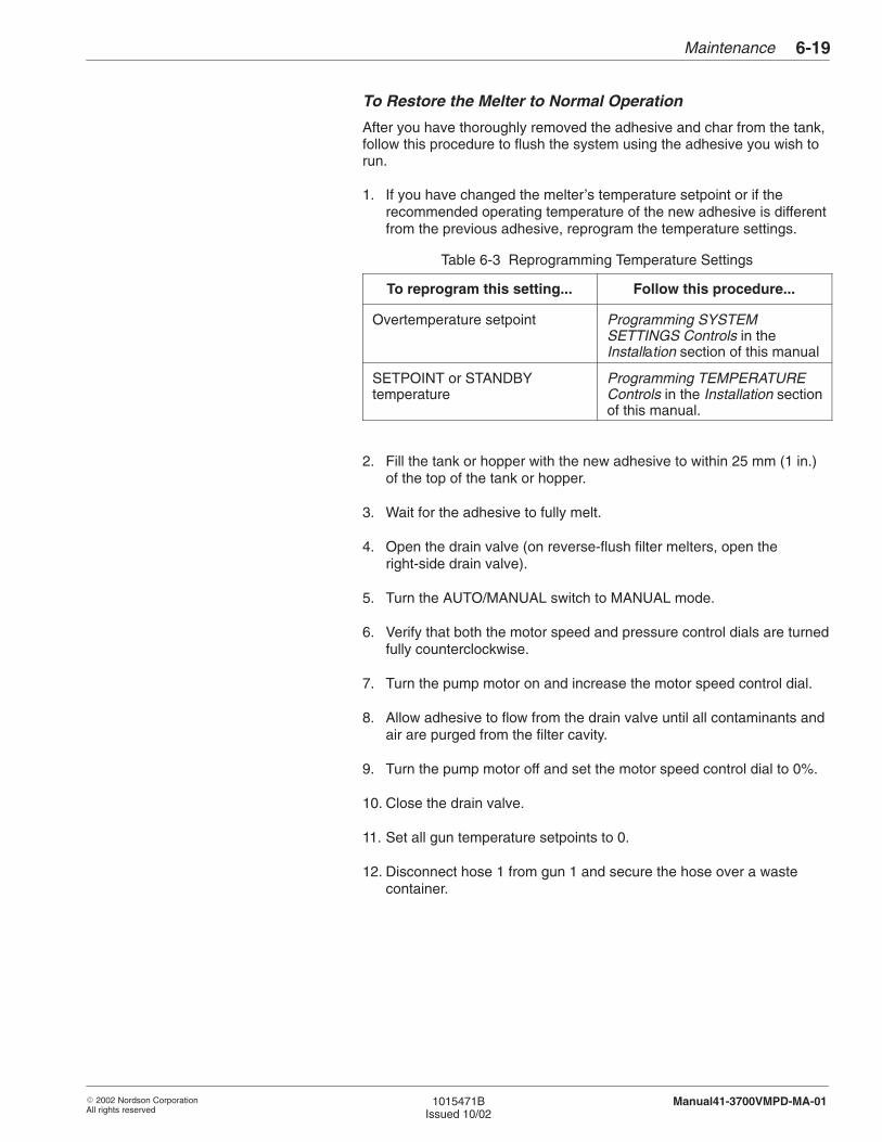
Maintenance 6-19
� 2002 Nordson CorporationAll rights reserved
1015471BIssued 10/02
Manual41-3700VMPD-MA-01
To Restore the Melter to Normal Operation
After you have thoroughly removed the adhesive and char from the tank,follow this procedure to flush the system using the adhesive you wish torun.
1. If you have changed the melter’s temperature setpoint or if therecommended operating temperature of the new adhesive is differentfrom the previous adhesive, reprogram the temperature settings.
Table 6-3 Reprogramming Temperature Settings
To reprogram this setting... Follow this procedure...
Overtemperature setpoint Programming SYSTEMSETTINGS Controls in theInstallation section of this manual
SETPOINT or STANDBYtemperature
Programming TEMPERATUREControls in the Installation sectionof this manual.
2. Fill the tank or hopper with the new adhesive to within 25 mm (1 in.)of the top of the tank or hopper.
3. Wait for the adhesive to fully melt.
4. Open the drain valve (on reverse-flush filter melters, open theright-side drain valve).
5. Turn the AUTO/MANUAL switch to MANUAL mode.
6. Verify that both the motor speed and pressure control dials are turnedfully counterclockwise.
7. Turn the pump motor on and increase the motor speed control dial.
8. Allow adhesive to flow from the drain valve until all contaminants andair are purged from the filter cavity.
9. Turn the pump motor off and set the motor speed control dial to 0%.
10. Close the drain valve.
11. Set all gun temperature setpoints to 0.
12. Disconnect hose 1 from gun 1 and secure the hose over a wastecontainer.
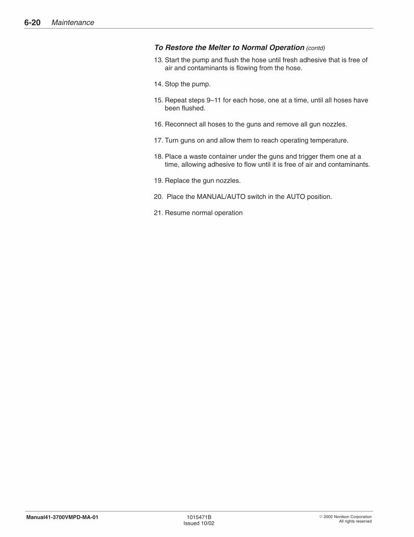
Maintenance6-20
� 2002 Nordson CorporationAll rights reserved
1015471BIssued 10/02
Manual41-3700VMPD-MA-01
To Restore the Melter to Normal Operation (contd)
13. Start the pump and flush the hose until fresh adhesive that is free ofair and contaminants is flowing from the hose.
14. Stop the pump.
15. Repeat steps 9–11 for each hose, one at a time, until all hoses havebeen flushed.
16. Reconnect all hoses to the guns and remove all gun nozzles.
17. Turn guns on and allow them to reach operating temperature.
18. Place a waste container under the guns and trigger them one at atime, allowing adhesive to flow until it is free of air and contaminants.
19. Replace the gun nozzles.
20. Place the MANUAL/AUTO switch in the AUTO position.
21. Resume normal operation

� 2002 Nordson CorporationAll rights reserved
1015471BIssued 10/02
Manual41-3700VMPD-MA-01
Section 7
Vista Controller
Vista Controller7-0
� 2002 Nordson CorporationAll rights reserved
1015471BIssued 10/02
Manual41-3700VMPD-MA-01
Vista Controller 7-1
� 2002 Nordson CorporationAll rights reserved
1015471BIssued 10/02
Manual41-3700VMPD-MA-01
Section 7Vista Controller
WARNING: Allow only qualified personnel to perform thefollowing tasks. Follow the safety instructions in this documentand all other related documentation.
This section includes control system troubleshooting procedures, andrepair procedures. Refer to the Parts section for the part number of anycomponent that needs to be replaced.
If you try all the troubleshooting suggestions in this section and still needassistance solving control system problems, call your Nordsonrepresentative.
The following sections of this manual contain additional information onthe control system:
� Description includes an overview of each of the functional areas ofthe operator panel.
� Installation includes procedures for connecting output contacts,connecting electrical service, and programming your melter.
� Wiring Diagrams includes a set of wiring diagrams for your system.
Refer to the Hydraulics section for troubleshooting procedures and repairprocedures, for the melter’s pump and motor. Refer to the Tank sectionfor manifold information.
1. Introduction
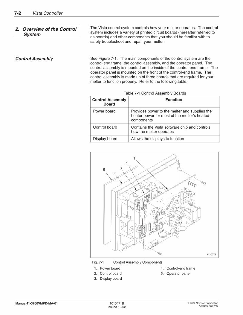
Vista Controller7-2
� 2002 Nordson CorporationAll rights reserved
1015471BIssued 10/02
Manual41-3700VMPD-MA-01
The Vista control system controls how your melter operates. The controlsystem includes a variety of printed circuit boards (hereafter referred toas boards) and other components that you should be familiar with tosafely troubleshoot and repair your melter.
See Figure 7-1. The main components of the control system are thecontrol-end frame, the control assembly, and the operator panel. Thecontrol assembly is mounted on the inside of the control-end frame. Theoperator panel is mounted on the front of the control-end frame. Thecontrol assembly is made up of three boards that are required for yourmelter to function properly. Refer to the following table.
Table 7-1 Control Assembly Boards
Control AssemblyBoard
Function
Power board Provides power to the melter and supplies theheater power for most of the melter’s heatedcomponents
Control board Contains the Vista software chip and controlshow the melter operates
Display board Allows the displays to function
4130076
1
+
12
3
45
Fig. 7-1 Control Assembly Components
1. Power board2. Control board3. Display board
4. Control-end frame5. Operator panel
2. Overview of the ControlSystem
Control Assembly
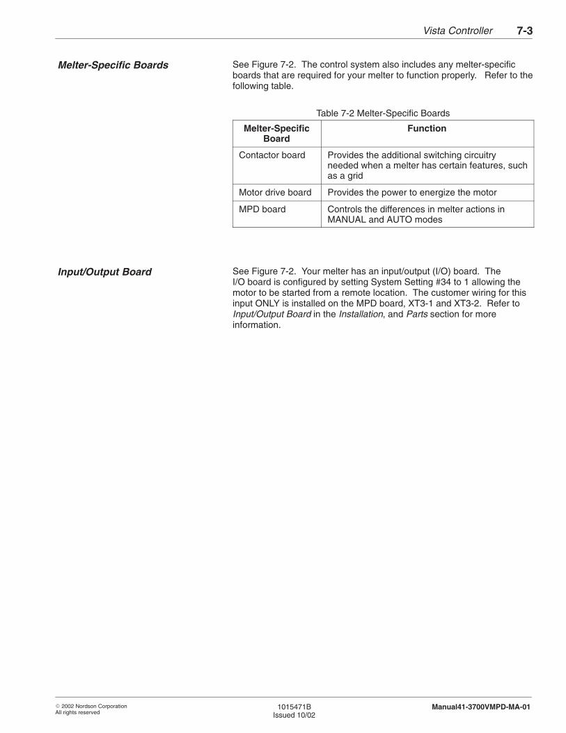
Vista Controller 7-3
� 2002 Nordson CorporationAll rights reserved
1015471BIssued 10/02
Manual41-3700VMPD-MA-01
See Figure 7-2. The control system also includes any melter-specificboards that are required for your melter to function properly. Refer to thefollowing table.
Table 7-2 Melter-Specific Boards
Melter-SpecificBoard
Function
Contactor board Provides the additional switching circuitryneeded when a melter has certain features, suchas a grid
Motor drive board Provides the power to energize the motor
MPD board Controls the differences in melter actions inMANUAL and AUTO modes
See Figure 7-2. Your melter has an input/output (I/O) board. TheI/O board is configured by setting System Setting #34 to 1 allowing themotor to be started from a remote location. The customer wiring for thisinput ONLY is installed on the MPD board, XT3-1 and XT3-2. Refer toInput/Output Board in the Installation, and Parts section for moreinformation.
Melter-Specific Boards
Input/Output Board
Vista Controller7-4
� 2002 Nordson CorporationAll rights reserved
1015471BIssued 10/02
Manual41-3700VMPD-MA-01
4131183A
3
1
2
45
Fig. 7-2 Melter-Specific Boards and I/O Board
1. Contactor board2. 5/6 hose/gun board
3. Motor drive board4. MPD board (or V-I board)
5. I/O board
Input/Output Board (contd)
Vista Controller 7-5
� 2002 Nordson CorporationAll rights reserved
1015471BIssued 10/02
Manual41-3700VMPD-MA-01
The following troubleshooting tables describe the kinds of control systemproblems you may encounter and provide corrective actions for handlingthose problems. When necessary, the tables refer to more detailedtroubleshooting procedures.
Refer to the appropriate troubleshooting table for the type of problem youare experiencing:
� Internal, Hose, or Gun Zone Not Heating� Settings Changed or Lost� Melter Not Powering On� Control System Indicating a Warning
- Out-Of-Band Warning- Under-Temperature (UT) Warning
� Control System Indicating a Fault- Over-Temperature (OT) Fault- Resistance Temperature Detector (RTD) Fault- Fault-Code Fault (F1–F7)
Before performing troubleshooting activities inside the melter’s electricalenclosure, you should exhaust all methods of troubleshooting theproblem with the electrical enclosure closed or with the power off. Thetroubleshooting tables and procedures in this section are organized usingthis methodology. In general, you should perform troubleshootingactivities as follows:
� Check the displays and lights for warnings, faults, and other statusinformation.
� Check your programmed settings to make sure they haven’t beenchanged. Refer to Records of System Settings in the Installationsection.
� Check for continuity and grounding between system components(melter, guns, hoses, and other equipment).
� Make sure your branch circuit disconnect switch is properly installed.
� Make sure your power supply is supplying the proper voltage.
� Prioritize troubleshooting activities to limit exposure to live power.Perform troubleshooting activities involving live power last.
� Understand your system electrically and mechanically before openingthe electrical enclosure. Pay special attention to system powerdistribution and to I/O interfaces with other equipment.
� Identify and eliminate potential electrical shock hazards in theenvironment surrounding your melter.
3. Troubleshooting Tables
Electrical Safety DuringTroubleshooting
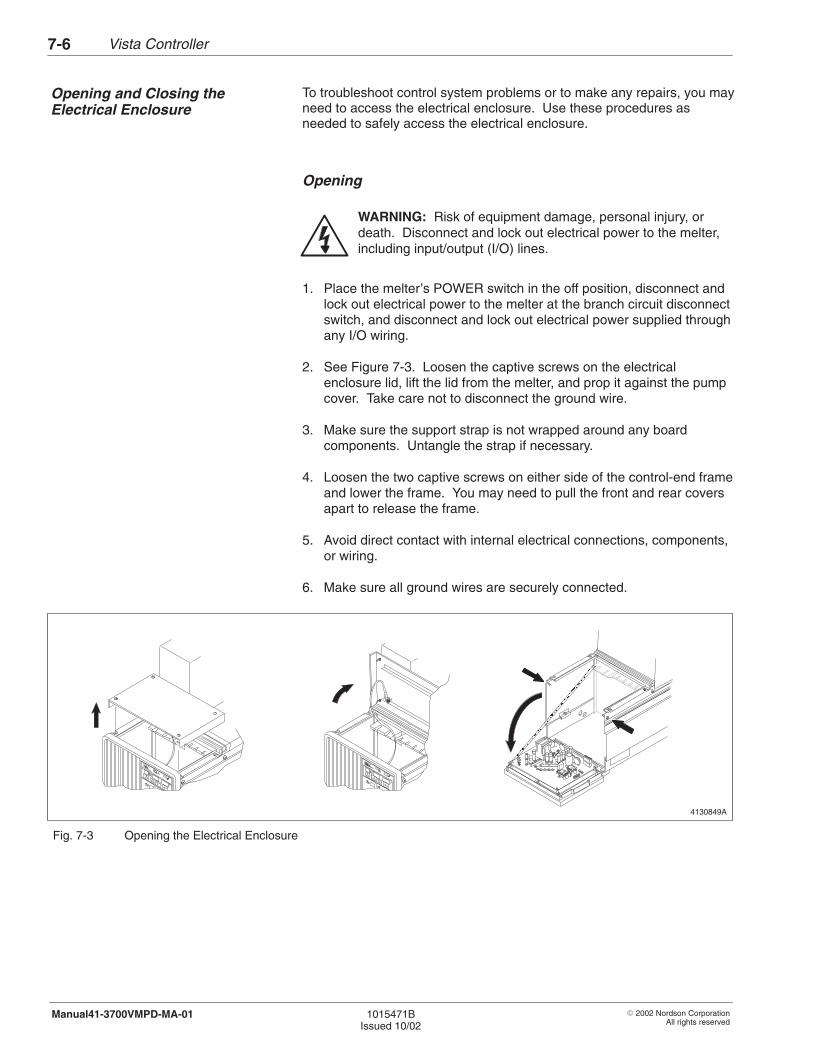
Vista Controller7-6
� 2002 Nordson CorporationAll rights reserved
1015471BIssued 10/02
Manual41-3700VMPD-MA-01
To troubleshoot control system problems or to make any repairs, you mayneed to access the electrical enclosure. Use these procedures asneeded to safely access the electrical enclosure.
Opening
WARNING: Risk of equipment damage, personal injury, ordeath. Disconnect and lock out electrical power to the melter,including input/output (I/O) lines.
1. Place the melter’s POWER switch in the off position, disconnect andlock out electrical power to the melter at the branch circuit disconnectswitch, and disconnect and lock out electrical power supplied throughany I/O wiring.
2. See Figure 7-3. Loosen the captive screws on the electricalenclosure lid, lift the lid from the melter, and prop it against the pumpcover. Take care not to disconnect the ground wire.
3. Make sure the support strap is not wrapped around any boardcomponents. Untangle the strap if necessary.
4. Loosen the two captive screws on either side of the control-end frameand lower the frame. You may need to pull the front and rear coversapart to release the frame.
5. Avoid direct contact with internal electrical connections, components,or wiring.
6. Make sure all ground wires are securely connected.
4130849A
ÎÎÎÎÎÎÎÎÎÎÎÎÎÎÎÎÎÎÎÎÎÎÎÎÎÎÎÎÎÎ
Fig. 7-3 Opening the Electrical Enclosure
Opening and Closing theElectrical Enclosure
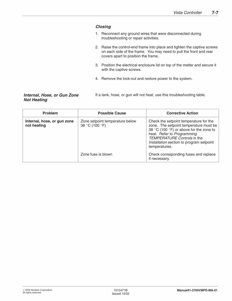
Vista Controller 7-7
� 2002 Nordson CorporationAll rights reserved
1015471BIssued 10/02
Manual41-3700VMPD-MA-01
Closing
1. Reconnect any ground wires that were disconnected duringtroubleshooting or repair activities.
2. Raise the control-end frame into place and tighten the captive screwson each side of the frame. You may need to pull the front and rearcovers apart to position the frame.
3. Position the electrical enclosure lid on top of the melter and secure itwith the captive screws.
4. Remove the lock-out and restore power to the system.
If a tank, hose, or gun will not heat, use this troubleshooting table.
Problem Possible Cause Corrective Action
Internal, hose, or gun zonenot heating
Zone setpoint temperature below38 �C (100 �F)
Check the setpoint temperature for thezone. The setpoint temperature must be38 �C (100 �F) or above for the zone toheat. Refer to ProgrammingTEMPERATURE Controls in theInstallation section to program setpointtemperatures.
Zone fuse is blown Check corresponding fuses and replaceif necessary.
Internal, Hose, or Gun ZoneNot Heating
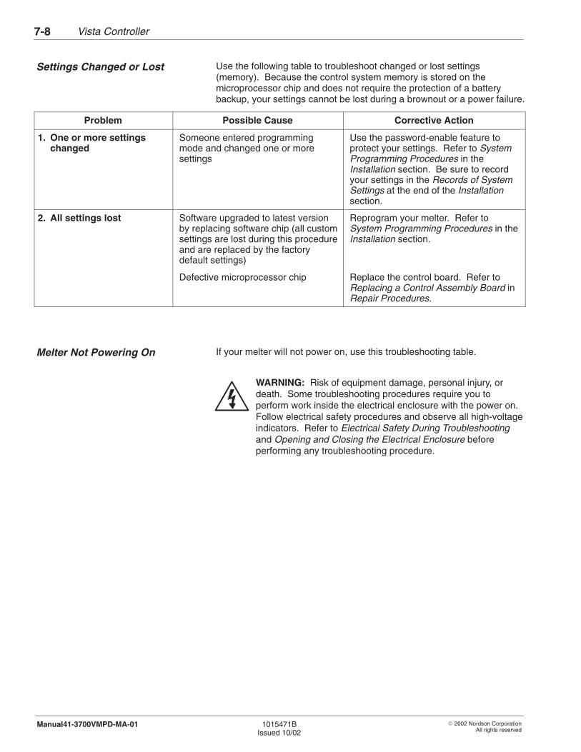
Vista Controller7-8
� 2002 Nordson CorporationAll rights reserved
1015471BIssued 10/02
Manual41-3700VMPD-MA-01
Use the following table to troubleshoot changed or lost settings(memory). Because the control system memory is stored on themicroprocessor chip and does not require the protection of a batterybackup, your settings cannot be lost during a brownout or a power failure.
Problem Possible Cause Corrective Action
1. One or more settingschanged
Someone entered programmingmode and changed one or moresettings
Use the password-enable feature toprotect your settings. Refer to SystemProgramming Procedures in theInstallation section. Be sure to recordyour settings in the Records of SystemSettings at the end of the Installationsection.
2. All settings lost Software upgraded to latest versionby replacing software chip (all customsettings are lost during this procedureand are replaced by the factorydefault settings)
Reprogram your melter. Refer toSystem Programming Procedures in theInstallation section.
Defective microprocessor chip Replace the control board. Refer toReplacing a Control Assembly Board inRepair Procedures.
If your melter will not power on, use this troubleshooting table.
WARNING: Risk of equipment damage, personal injury, ordeath. Some troubleshooting procedures require you toperform work inside the electrical enclosure with the power on.Follow electrical safety procedures and observe all high-voltageindicators. Refer to Electrical Safety During Troubleshootingand Opening and Closing the Electrical Enclosure beforeperforming any troubleshooting procedure.
Settings Changed or Lost
Melter Not Powering On
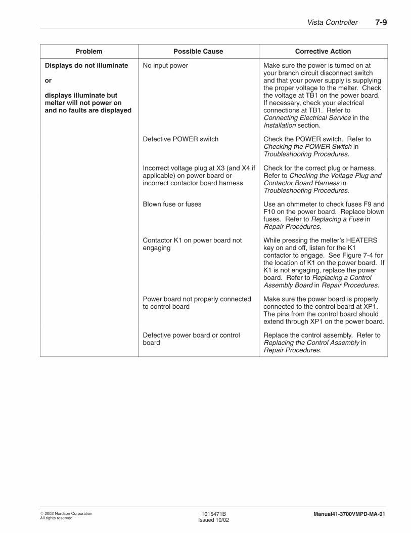
Vista Controller 7-9
� 2002 Nordson CorporationAll rights reserved
1015471BIssued 10/02
Manual41-3700VMPD-MA-01
Problem Possible Cause Corrective Action
Displays do not illuminate
or
displays illuminate butmelter will not power onand no faults are displayed
No input power Make sure the power is turned on atyour branch circuit disconnect switchand that your power supply is supplyingthe proper voltage to the melter. Checkthe voltage at TB1 on the power board.If necessary, check your electricalconnections at TB1. Refer toConnecting Electrical Service in theInstallation section.
Defective POWER switch Check the POWER switch. Refer toChecking the POWER Switch inTroubleshooting Procedures.
Incorrect voltage plug at X3 (and X4 ifapplicable) on power board orincorrect contactor board harness
Check for the correct plug or harness.Refer to Checking the Voltage Plug andContactor Board Harness inTroubleshooting Procedures.
Blown fuse or fuses Use an ohmmeter to check fuses F9 andF10 on the power board. Replace blownfuses. Refer to Replacing a Fuse inRepair Procedures.
Contactor K1 on power board notengaging
While pressing the melter’s HEATERSkey on and off, listen for the K1contactor to engage. See Figure 7-4 forthe location of K1 on the power board. IfK1 is not engaging, replace the powerboard. Refer to Replacing a ControlAssembly Board in Repair Procedures.
Power board not properly connectedto control board
Make sure the power board is properlyconnected to the control board at XP1.The pins from the control board shouldextend through XP1 on the power board.
Defective power board or controlboard
Replace the control assembly. Refer toReplacing the Control Assembly inRepair Procedures.
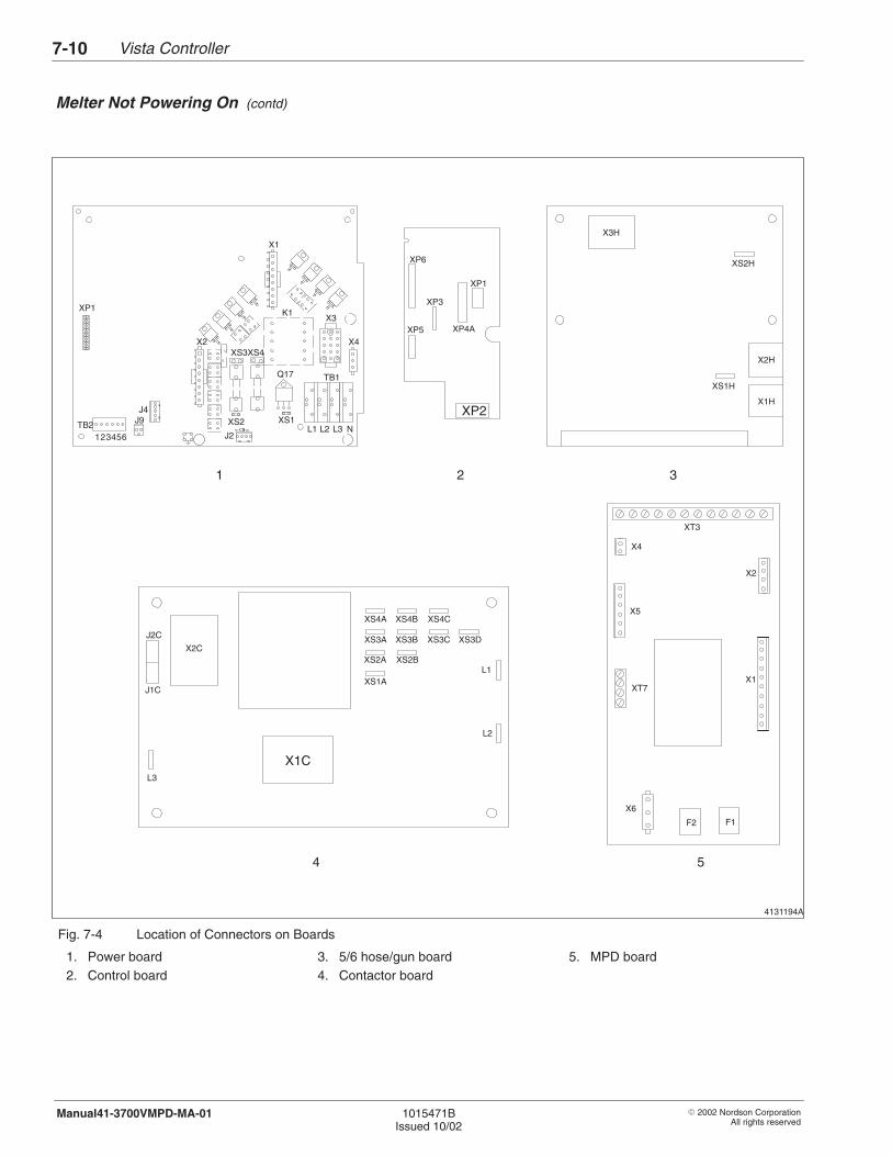
Vista Controller7-10
� 2002 Nordson CorporationAll rights reserved
1015471BIssued 10/02
Manual41-3700VMPD-MA-01
4131194A
TB1
L1 L2 L3 NJ2
TB2123456
J4
X2
X1
XS2 XS1J9
Q17
X3
X4
XP1
XS4XS3
X3H
XS2H
XS1H
X2H
X2C
J2C
J1C
X1C
XS4A XS4B XS4C
XS3A XS3B XS3C XS3D
XS2A XS2B
XS1AL1
L2
L3
1 3
4 5
X1H
2
XP6
XP4A
XP1
XP5
XP3
XP2
K1
X2
X4
XT3
X6
X1
X5
XT7
F2 F1
Fig. 7-4 Location of Connectors on Boards
1. Power board2. Control board
3. 5/6 hose/gun board4. Contactor board
5. MPD board
Melter Not Powering On (contd)
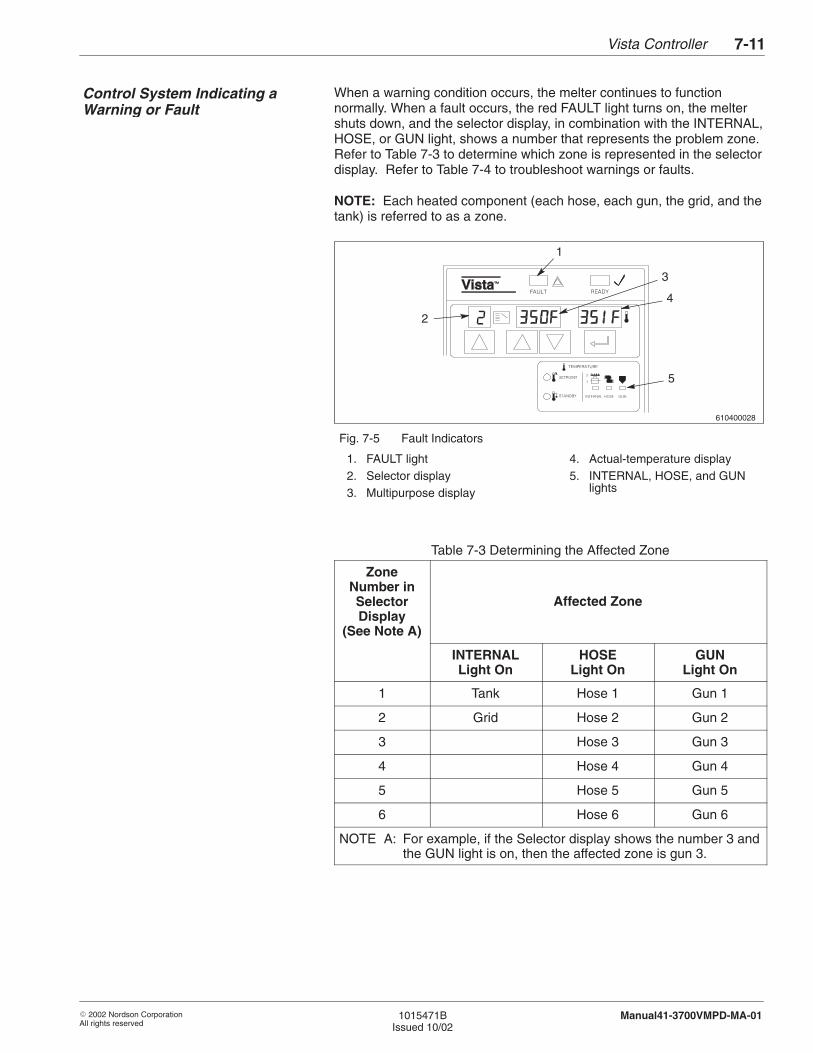
Vista Controller 7-11
� 2002 Nordson CorporationAll rights reserved
1015471BIssued 10/02
Manual41-3700VMPD-MA-01
When a warning condition occurs, the melter continues to functionnormally. When a fault occurs, the red FAULT light turns on, the meltershuts down, and the selector display, in combination with the INTERNAL,HOSE, or GUN light, shows a number that represents the problem zone.Refer to Table 7-3 to determine which zone is represented in the selectordisplay. Refer to Table 7-4 to troubleshoot warnings or faults.
NOTE: Each heated component (each hose, each gun, the grid, and thetank) is referred to as a zone.
610400028
2
1
3
4
5
Fig. 7-5 Fault Indicators
1. FAULT light2. Selector display3. Multipurpose display
4. Actual-temperature display5. INTERNAL, HOSE, and GUN
lights
Table 7-3 Determining the Affected Zone
ZoneNumber inSelectorDisplay
(See Note A)
Affected Zone
INTERNALLight On
HOSELight On
GUNLight On
1 Tank Hose 1 Gun 1
2 Grid Hose 2 Gun 2
3 Hose 3 Gun 3
4 Hose 4 Gun 4
5 Hose 5 Gun 5
6 Hose 6 Gun 6
NOTE A: For example, if the Selector display shows the number 3 andthe GUN light is on, then the affected zone is gun 3.
Control System Indicating aWarning or Fault
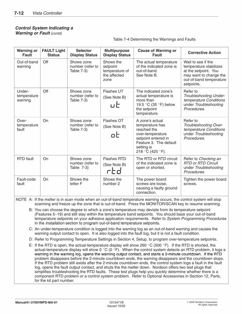
Vista Controller7-12
� 2002 Nordson CorporationAll rights reserved
1015471BIssued 10/02
Manual41-3700VMPD-MA-01
Table 7-4 Determining the Warnings and Faults
Warning orFault
FAULT LightStatus
SelectorDisplay Status
MultipurposeDisplay Status
Cause of Warning orFault Corrective Action
Out-of-bandwarning
Off Shows zonenumber (refer toTable 7-3)
Shows thesetpointtemperature ofthe affectedzone
The actual temperatureof the indicated zone isout-of-band. See Note B.
Wait to see if thetemperature stabilizesat the setpoint. Youmay want to change theout-of-band temperaturesetpoints.
Under-temperaturewarning
Off Shows zonenumber (refer toTable 7-3)
Flashes UT
(See Note B)
The indicated zone’sactual temperature ismore than19.5 �C (35 �F) belowthe setpointtemperature.
Refer toTroubleshooting Under-temperature Conditionsunder TroubleshootingProcedures.
Over-temperaturefault
On Shows zonenumber (refer toTable 7-3)
Flashes OT
(See Note B)
A zone’s actualtemperature hasreached theover-temperaturesetpoint entered inFeature 3. The defaultsetting is218 �C (425 �F).
Refer toTroubleshooting Over-temperature Conditionsunder TroubleshootingProcedures.
RTD fault On Shows zonenumber (refer toTable 7-3)
Flashes RTD
(See Note B)
The RTD or RTD circuitof the indicated zone isopen or shorted.
Refer to Checking anRTD or RTD Circuitunder TroubleshootingProcedures.
Fault-codefault
On Shows theletter F
Shows thenumber 2
The power boardscrews are loose, causing a faulty groundconnection.
Tighten the power boardscrews.
NOTE A: If the melter is in scan mode when an out-of-band temperature warning occurs, the control system will stopscanning and freeze up the zone that is out-of-band. Press the MONITOR/SCAN key to resume scanning.
B: You can choose the degree to which a zone’s temperature may deviate from its temperature setpoint(Features 5–19) and still stay within the temperature band setpoints. You should base your out-of-bandtemperature setpoints on your adhesive application requirements. Refer to System Programming Proceduresin the Installation section to program out-of-band temperature setpoints.in the Installation section to rogram out of band tem erature set oints.
C: An under-temperature condition is logged into the warning log as an out-of-band warning and causes thewarning output contact to open. It is also logged into the fault log, but it is not a fault condition.
D: Refer to Programming Temperature Settings in Section 4, Setup, to program over-temperature setpoints.
E: If the RTD is open, the actual-temperature display will show 260 �C (500 �F). If the RTD is shorted, theactual-temperature display will show 0 �C (0 �F). When the control system detects an RTD problem, it logs awarning in the warning log opens the warning output contact and starts a 2-minute countdown If the RTDwarning in the warning log, opens the warning output contact, and starts a 2-minute countdown. If the RTDproblem disappears before the 2-minute countdown ends, the warning disappears and the countdown stops.If the RTD problem still exists after the 2-minute countdown ends, the control system logs a fault in the faultlog, opens the fault output contact, and shuts the the melter down. Nordson offers two test plugs thatsimplifies troubleshooting the RTD faults. These test plugs help you quickly determine whether there is acomponent RTD problem or a control system problem. Refer to Optional Accessories in Section 12, Parts,for the kit part number.
Control System Indicating aWarning or Fault (contd)
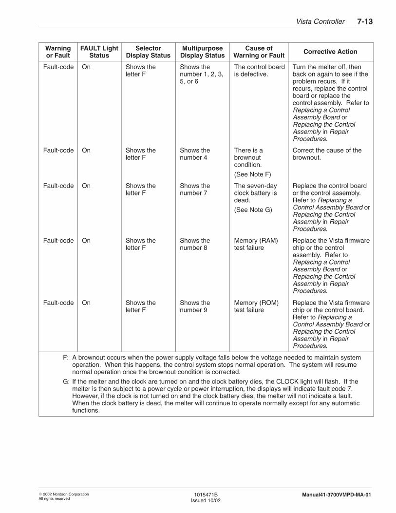
Vista Controller 7-13
� 2002 Nordson CorporationAll rights reserved
1015471BIssued 10/02
Manual41-3700VMPD-MA-01
Warningor Fault
FAULT LightStatus
SelectorDisplay Status
MultipurposeDisplay Status
Cause ofWarning or Fault Corrective Action
Fault-code On Shows theletter F
Shows thenumber 1, 2, 3,5, or 6
The control boardis defective.
Turn the melter off, thenback on again to see if theproblem recurs. If itrecurs, replace the controlboard or replace thecontrol assembly. Refer toReplacing a ControlAssembly Board orReplacing the ControlAssembly in RepairProcedures.
Fault-code On Shows theletter F
Shows thenumber 4
There is abrownoutcondition.
(See Note F)
Correct the cause of thebrownout.
Fault-code On Shows theletter F
Shows thenumber 7
The seven-dayclock battery isdead.
(See Note G)
Replace the control boardor the control assembly.Refer to Replacing aControl Assembly Board orReplacing the ControlAssembly in RepairProcedures.
Fault-code On Shows theletter F
Shows thenumber 8
Memory (RAM)test failure
Replace the Vista firmwarechip or the controlassembly. Refer toReplacing a ControlAssembly Board orReplacing the ControlAssembly in RepairProcedures.
Fault-code On Shows theletter F
Shows thenumber 9
Memory (ROM)test failure
Replace the Vista firmwarechip or the control board.Refer to Replacing aControl Assembly Board orReplacing the ControlAssembly in RepairProcedures.
F: A brownout occurs when the power supply voltage falls below the voltage needed to maintain systemoperation. When this happens, the control system stops normal operation. The system will resumenormal operation once the brownout condition is corrected.
G: If the melter and the clock are turned on and the clock battery dies, the CLOCK light will flash. If themelter is then subject to a power cycle or power interruption, the displays will indicate fault code 7.However, if the clock is not turned on and the clock battery dies, the melter will not indicate a fault.When the clock battery is dead, the melter will continue to operate normally except for any automaticfunctions.
Vista Controller7-14
� 2002 Nordson CorporationAll rights reserved
1015471BIssued 10/02
Manual41-3700VMPD-MA-01
Use these procedures as directed in Troubleshooting Tables to furthertroubleshoot control system problems.
Follow this procedure to check the POWER switch.
WARNING: Risk of equipment damage, personal injury, ordeath. This procedure requires you to perform electricaltroubleshooting with the power on. Use extreme caution andrefer to Electrical Safety During Troubleshooting and Openingand Closing the Electrical Enclosure for instructions on safelyworking inside the electrical enclosure.
1. Turn on power to the melter at the branch circuit disconnect switch.
2. With the melter’s POWER switch in the off position, measure thevoltage across J4 positions 1 and 4 on the power board.
� Voltage does not measure 230 VAC: replace the POWER switchand harness.
� Voltage measures 230 VAC: normal indication. Continue to thenext step.
3. With the melter’s POWER switch in the on position, measure thevoltage across J4 positions 2 and 5 on the power board.
� Voltage does not measure 230 VAC: replace the POWER switchand harness.
� Voltage measures 230 VAC: normal indication. Return to theMelter Not Powering On troubleshooting table.
4. TroubleshootingProcedures
Checking the POWER Switch
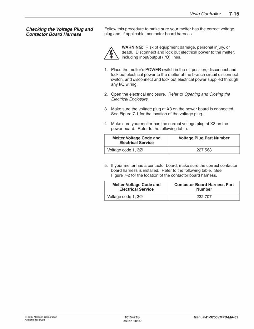
Vista Controller 7-15
� 2002 Nordson CorporationAll rights reserved
1015471BIssued 10/02
Manual41-3700VMPD-MA-01
Follow this procedure to make sure your melter has the correct voltageplug and, if applicable, contactor board harness.
WARNING: Risk of equipment damage, personal injury, ordeath. Disconnect and lock out electrical power to the melter,including input/output (I/O) lines.
1. Place the melter’s POWER switch in the off position, disconnect andlock out electrical power to the melter at the branch circuit disconnectswitch, and disconnect and lock out electrical power supplied throughany I/O wiring.
2. Open the electrical enclosure. Refer to Opening and Closing theElectrical Enclosure.
3. Make sure the voltage plug at X3 on the power board is connected.See Figure 7-1 for the location of the voltage plug.
4. Make sure your melter has the correct voltage plug at X3 on thepower board. Refer to the following table.
Melter Voltage Code andElectrical Service
Voltage Plug Part Number
Voltage code 1, 3∅ 227 568
5. If your melter has a contactor board, make sure the correct contactorboard harness is installed. Refer to the following table. SeeFigure 7-2 for the location of the contactor board harness.
Melter Voltage Code andElectrical Service
Contactor Board Harness PartNumber
Voltage code 1, 3∅ 232 707
Checking the Voltage Plug andContactor Board Harness
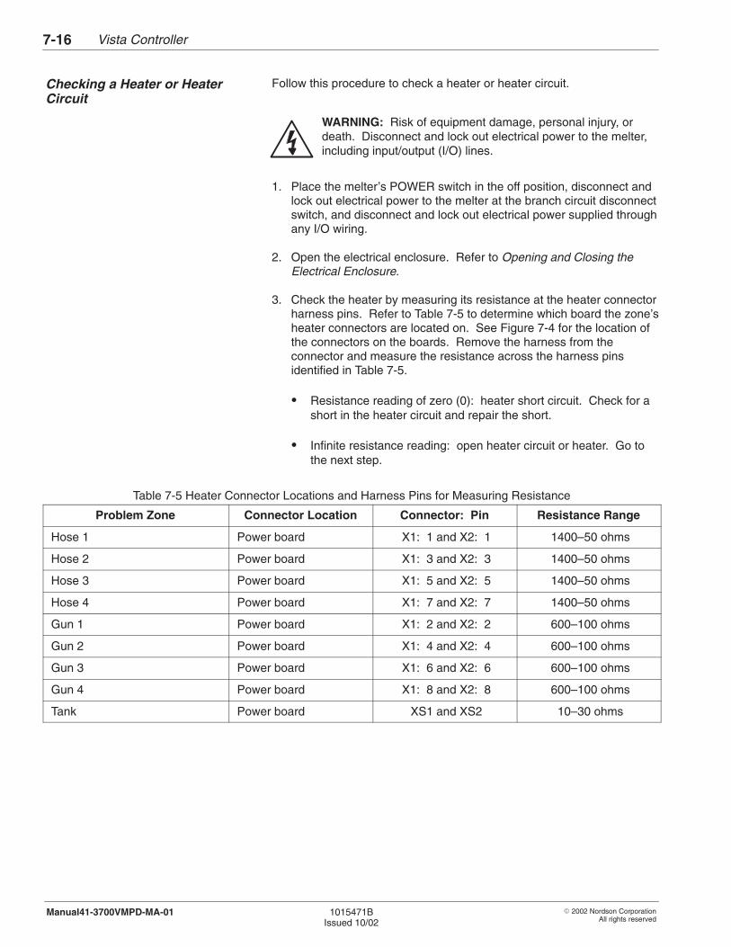
Vista Controller7-16
� 2002 Nordson CorporationAll rights reserved
1015471BIssued 10/02
Manual41-3700VMPD-MA-01
Follow this procedure to check a heater or heater circuit.
WARNING: Risk of equipment damage, personal injury, ordeath. Disconnect and lock out electrical power to the melter,including input/output (I/O) lines.
1. Place the melter’s POWER switch in the off position, disconnect andlock out electrical power to the melter at the branch circuit disconnectswitch, and disconnect and lock out electrical power supplied throughany I/O wiring.
2. Open the electrical enclosure. Refer to Opening and Closing theElectrical Enclosure.
3. Check the heater by measuring its resistance at the heater connectorharness pins. Refer to Table 7-5 to determine which board the zone’sheater connectors are located on. See Figure 7-4 for the location ofthe connectors on the boards. Remove the harness from theconnector and measure the resistance across the harness pinsidentified in Table 7-5.
� Resistance reading of zero (0): heater short circuit. Check for ashort in the heater circuit and repair the short.
� Infinite resistance reading: open heater circuit or heater. Go tothe next step.
Table 7-5 Heater Connector Locations and Harness Pins for Measuring Resistance
Problem Zone Connector Location Connector: Pin Resistance Range
Hose 1 Power board X1: 1 and X2: 1 1400–50 ohms
Hose 2 Power board X1: 3 and X2: 3 1400–50 ohms
Hose 3 Power board X1: 5 and X2: 5 1400–50 ohms
Hose 4 Power board X1: 7 and X2: 7 1400–50 ohms
Gun 1 Power board X1: 2 and X2: 2 600–100 ohms
Gun 2 Power board X1: 4 and X2: 4 600–100 ohms
Gun 3 Power board X1: 6 and X2: 6 600–100 ohms
Gun 4 Power board X1: 8 and X2: 8 600–100 ohms
Tank Power board XS1 and XS2 10–30 ohms
Checking a Heater or HeaterCircuit
Vista Controller 7-17
� 2002 Nordson CorporationAll rights reserved
1015471BIssued 10/02
Manual41-3700VMPD-MA-01
4. Check the continuity of the heater circuit by measuring the heaterresistance at a point in the circuit that is closer to the heater.
� If the faulted zone is a hose or gun, measure the resistance at thehose or gun electrical plug. Refer to your hose or gun manual fora diagram of the electrical plug and for procedures for replacingthe gun heater. If a hose heater is defective, replace the hose.
� If the faulted zone is a tank, measure the resistance at the tankheater connectors (refer to Table 7-5). If you measure infinite orzero (0) resistance at the tank or heater connectors, you mustinstall a new tank. Refer to the Tank section.
5. If you do not find a continuity problem, replace the control board orthe control assembly. Refer to Replacing a Control Assembly Boardor Replacing the Control Assembly in Repair Procedures.
Use this procedure to check a thermostat.
WARNING: System or material pressurized. Relieve pressure.Failure to observe this warning may result in serious burns.
1. Relieve system pressure. Refer to Relieving System Pressure in theMaintenance section.
WARNING: Risk of equipment damage, personal injury, ordeath. Disconnect and lock out electrical power to the melter,including input/output (I/O) lines.
2. Place the melter’s POWER switch in the off position, disconnect andlock out electrical power to the melter at the branch circuit disconnectswitch, and disconnect and lock out electrical power supplied throughany I/O wiring.
3. Open the electrical enclosure. Refer to Opening and Closing theElectrical Enclosure.
4. Remove the thermostat. Refer to RTD or Thermostat Removal inRepair Procedures.
Checking a Thermostat

Vista Controller7-18
� 2002 Nordson CorporationAll rights reserved
1015471BIssued 10/02
Manual41-3700VMPD-MA-01
5. Connect an ohmmeter set on the lowest resistance scale across thethermostat; then heat the thermostat with a flameless electric heatgun.
� Short circuit before thermostat reaches temperature and opencircuit when thermostat reaches temperature: normal indication.Return to the appropriate troubleshooting table.
� Short circuit or low resistance at high temperature: defectivethermostat. Replace the thermostat. Refer to Replacing an RTDor a Thermostat in Repair Procedures.
Follow this procedure to troubleshoot under-temperature (UT) warnings.
WARNING: Risk of equipment damage, personal injury, ordeath. Some troubleshooting procedures require you toperform work inside the electrical enclosure with the power on.Follow electrical safety procedures and observe all high-voltageindicators. Refer to Electrical Safety During Troubleshootingand Opening and Closing the Electrical Enclosure beforeperforming any troubleshooting procedure.
1. Press the CLEAR FAULTS key and wait for the system to return tothe system-ready state.
2. If the warning disappears and the melter appears to be workingagain, the voltage to the melter may have temporarily sagged or youmay have an intermittent problem. Repetitive warnings in the samezone indicate a problem with the circuitry in that zone or anintermittent RTD failure. Take the following steps to troubleshootintermittent under-temperature warnings:
a. Check for a change in environmental conditions, such as addedventilation or sources of drafts. A cold draft can keep your melter,hoses, and guns from heating.
b. Make sure the power is turned on at your branch circuitdisconnect switch and that your power supply is supplying theproper voltage to the melter.
c. Check all hose and gun electrical plugs. Make sure theconnections are tight and free of corrosion.
TroubleshootingUnder-Temperature Conditions

Vista Controller 7-19
� 2002 Nordson CorporationAll rights reserved
1015471BIssued 10/02
Manual41-3700VMPD-MA-01
d. Check your operating temperature setpoints to make sure theyhaven’t been changed. Refer to Records of System Settings inthe Installation section.
e. If the affected zone is a hose or gun, replace the hose or gun witha hose or gun that is known to be good. If the warningdisappears, replace the defective hose or gun. If the warning stillappears, continue to the next step.
3. If the warning still appears after you press the CLEAR FAULTS keyand after you have taken the actions in step 2, take the followingsteps.
a. Check for loose heater connections on the board that supplies theheater power for the affected zone. Refer to Table 7-5 for heaterconnector locations. For example, check the harnessesconnected to X1 and X2 on the power board to check the heaterconnections for hoses 1–4 or guns 1–4. See Figure 7-4 for thelocation of connectors on boards.
b. Use an ohmmeter to check the fuse or fuses on the board thatsupplies the heater power for the affected zone. Refer toFigure 7-7 for fuse locations. Replace the appropriate fuse orfuses. Refer to Replacing a Fuse in Repair Procedures. If thefuse blows again, make sure the heater is not shorted to theground.
c. If the affected zone is the tank, make sure the harness connectedto J2 on the power board is secure or check the thermostat. SeeFigure 7-4 for the location of J2 on the power board. To check athermostat, refer to Checking a Thermostat in TroubleshootingProcedures.
d. Check the K1 contactor on the power board. While pressing themelter’s HEATERS key on and off, listen for the K1 contactor toengage. See Figure 7-4 for the location of K1 on the powerboard. If K1 is not engaging, replace the power board. Refer toReplacing a Control Assembly Board in Repair Procedures.
e. Check the heater or heater circuit of the affected zone. Refer toChecking a Heater or Heater Circuit in TroubleshootingProcedures.
f. If the warning condition still appears after you have taken all theactions in this step, replace the control assembly. Refer toReplacing the Control Assembly in Repair Procedures.
Vista Controller7-20
� 2002 Nordson CorporationAll rights reserved
1015471BIssued 10/02
Manual41-3700VMPD-MA-01
Follow this procedure to troubleshoot over-temperature (OT) warnings.
WARNING: Risk of equipment damage, personal injury, ordeath. Some troubleshooting procedures require you toperform work inside the electrical enclosure with the power on.Follow electrical safety procedures and observe all high-voltageindicators. Refer to Electrical Safety During Troubleshootingand Opening and Closing the Electrical Enclosure beforeperforming any troubleshooting procedure.
1. Press the CLEAR FAULTS key.
2. If the fault disappears and the melter appears to be working again,you may have an intermittent problem. Repetitive faults in the samezone indicate a problem with the circuitry in that zone or anintermittent RTD failure. Electrical noise from DC-drive motors maycause the triacs that control heater power on the power board toclose independent of the control system. Take the following steps totroubleshoot intermittent over-temperature faults:
a. Check your operating temperature setpoints to make sure theyhaven’t been changed. Refer to Records of System Settings inthe Installation section.
b. To verify that something other than the control system is affectinga heated zone, turn on the Display Heater Proportioning feature(Feature No. 21) for the affected zone. When the display blinkson and off, it means the control system is proportioning heatcontrol to the heater. During proportioning, the temperaturedisplayed for the zone should stay fairly constant, within +/–1 °F.If the temperature continues to rise during proportioning, thensomething other than the control system is closing the triacs onthe power board and causing the heaters to heat. If electricalnoise from DC drives is causing the overheating problem, thenyou may be experiencing problems with other equipment in yourfacility. Take the following steps to solve electrical noiseproblems:
� Install the proper line reactor. Consult with the DC drivemanufacturer for the appropriate line reactor size.
� Electrically ground the hot melt melter to the parent machineusing as short a length of twisted cable as possible.
� If the triacs continue to close after the hot melt melter isgrounded to the parent machine, install a line filter on eachinput power line to the hot melt melter. Connect the filterline-to-line. Refer to Parts for the line filter part number. For athree-phase system, order three filters.
TroubleshootingOver-Temperature Conditions
Vista Controller 7-21
� 2002 Nordson CorporationAll rights reserved
1015471BIssued 10/02
Manual41-3700VMPD-MA-01
c. If the faulted zone is a hose or gun, replace the hose or gun with ahose or gun that is known to be good. If the fault disappears,replace the defective hose or gun. If the fault remains, continue tothe next step.
3. If the fault remains after you press the CLEAR FAULTS key and afteryou have taken the actions in step 2, check the heater or heatercircuit of the faulted zone. Refer to Checking a Heater or HeaterCircuit in Troubleshooting Procedures.
4. If the fault remains after you have taken all the actions in thisprocedure, replace the control assembly. Refer to Replacing theControl Assembly in Repair Procedures.
Follow this procedure to check an RTD or RTD circuit.
NOTE: If the faulted zone is a hose or a gun, you can remove the hoseor gun and replace it with a hose or gun that is known to be good. If thefault disappears, then the problem is in the hose or gun, not inside themelter. As an alternative to using this procedure, you can refer to yourhose or gun manual for instructions on checking the hose or gun RTDand replacing the gun RTD.
WARNING: Risk of equipment damage, personal injury, ordeath. Disconnect and lock out electrical power to the melter,including input/output (I/O) lines.
1. Place the melter’s POWER switch in the off position, disconnect andlock out electrical power to the melter at the branch circuit disconnectswitch, and disconnect and lock out electrical power supplied throughany I/O wiring.
2. Open the electrical enclosure. Refer to Opening and Closing theElectrical Enclosure.
3. Check the RTD by measuring its resistance. Refer to Table 7-6.
� If the RTD is defective, replace the RTD. If a hose RTD isdefective, you must replace the hose. To replace a gun RTD,refer to your gun manual. To replace a tank RTD, refer toReplacing an RTD or a Thermostat in Repair Procedures.
NOTE: Flex the hose when you are checking a hose RTD. Somehose RTDs exhibit problems intermittently.
� If the RTD is good, go to the next step.
Troubleshooting an RTD orRTD Circuit
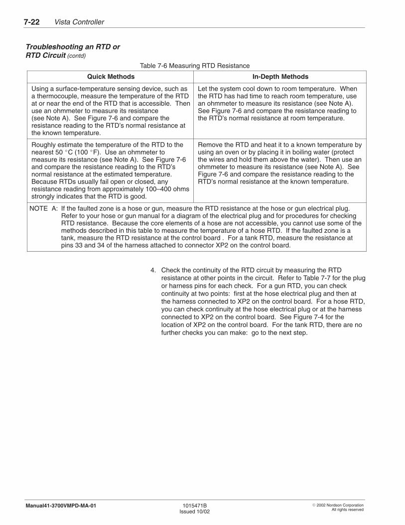
Vista Controller7-22
� 2002 Nordson CorporationAll rights reserved
1015471BIssued 10/02
Manual41-3700VMPD-MA-01
Table 7-6 Measuring RTD Resistance
Quick Methods In-Depth Methods
Using a surface-temperature sensing device, such asa thermocouple, measure the temperature of the RTDat or near the end of the RTD that is accessible. Thenuse an ohmmeter to measure its resistance(see Note A). See Figure 7-6 and compare theresistance reading to the RTD’s normal resistance atthe known temperature.
Let the system cool down to room temperature. Whenthe RTD has had time to reach room temperature, usean ohmmeter to measure its resistance (see Note A).See Figure 7-6 and compare the resistance reading tothe RTD’s normal resistance at room temperature.
Roughly estimate the temperature of the RTD to thenearest 50 �C (100 �F). Use an ohmmeter tomeasure its resistance (see Note A). See Figure 7-6and compare the resistance reading to the RTD’snormal resistance at the estimated temperature.Because RTDs usually fail open or closed, anyresistance reading from approximately 100–400 ohmsstrongly indicates that the RTD is good.
Remove the RTD and heat it to a known temperature byusing an oven or by placing it in boiling water (protectthe wires and hold them above the water). Then use anohmmeter to measure its resistance (see Note A). SeeFigure 7-6 and compare the resistance reading to theRTD’s normal resistance at the known temperature.
NOTE A: If the faulted zone is a hose or gun, measure the RTD resistance at the hose or gun electrical plug.Refer to your hose or gun manual for a diagram of the electrical plug and for procedures for checkingRTD resistance. Because the core elements of a hose are not accessible, you cannot use some of themethods described in this table to measure the temperature of a hose RTD. If the faulted zone is atank, measure the RTD resistance at the control board . For a tank RTD, measure the resistance atpins 33 and 34 of the harness attached to connector XP2 on the control board.
4. Check the continuity of the RTD circuit by measuring the RTDresistance at other points in the circuit. Refer to Table 7-7 for the plugor harness pins for each check. For a gun RTD, you can checkcontinuity at two points: first at the hose electrical plug and then atthe harness connected to XP2 on the control board. For a hose RTD,you can check continuity at the hose electrical plug or at the harnessconnected to XP2 on the control board. See Figure 7-4 for thelocation of XP2 on the control board. For the tank RTD, there are nofurther checks you can make: go to the next step.
Troubleshooting an RTD orRTD Circuit (contd)
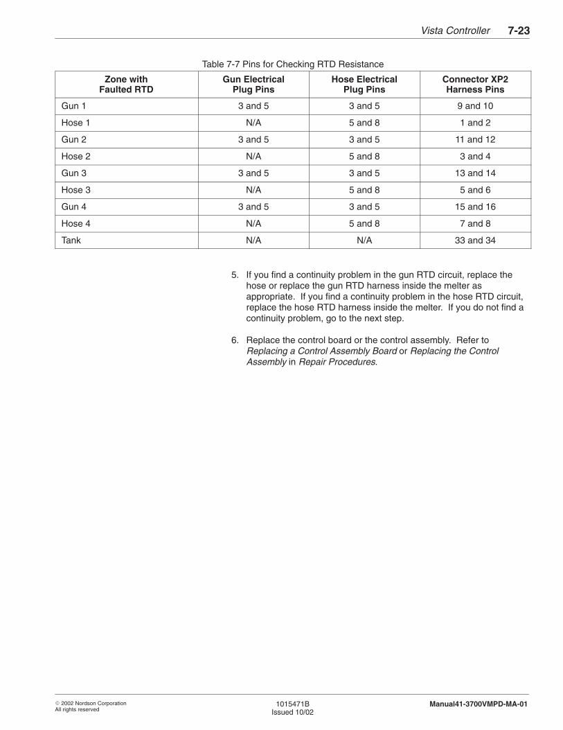
Vista Controller 7-23
� 2002 Nordson CorporationAll rights reserved
1015471BIssued 10/02
Manual41-3700VMPD-MA-01
Table 7-7 Pins for Checking RTD Resistance
Zone withFaulted RTD
Gun ElectricalPlug Pins
Hose ElectricalPlug Pins
Connector XP2Harness Pins
Gun 1 3 and 5 3 and 5 9 and 10
Hose 1 N/A 5 and 8 1 and 2
Gun 2 3 and 5 3 and 5 11 and 12
Hose 2 N/A 5 and 8 3 and 4
Gun 3 3 and 5 3 and 5 13 and 14
Hose 3 N/A 5 and 8 5 and 6
Gun 4 3 and 5 3 and 5 15 and 16
Hose 4 N/A 5 and 8 7 and 8
Tank N/A N/A 33 and 34
5. If you find a continuity problem in the gun RTD circuit, replace thehose or replace the gun RTD harness inside the melter asappropriate. If you find a continuity problem in the hose RTD circuit,replace the hose RTD harness inside the melter. If you do not find acontinuity problem, go to the next step.
6. Replace the control board or the control assembly. Refer toReplacing a Control Assembly Board or Replacing the ControlAssembly in Repair Procedures.
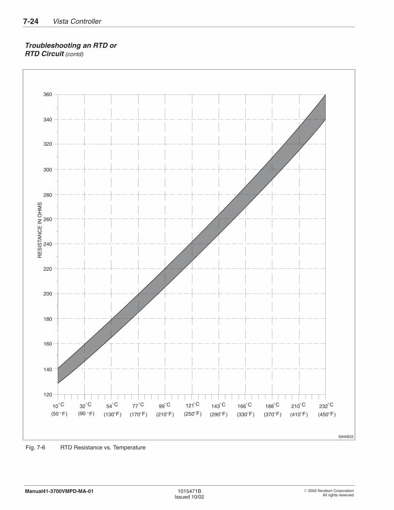
Vista Controller7-24
� 2002 Nordson CorporationAll rights reserved
1015471BIssued 10/02
Manual41-3700VMPD-MA-01
�F
5940833
�F (130 )
�C54
�F �F
�C�C�C
(170 )
�C �C77 99 121 143 166 188 210 232�C �C �C
�F (290 )(210 )�F (250 )�F (370 )�F (410 )�F (450 )�F(330 )�F
160
360
340
320
300
280
260
240
220
200
180
140
120
RE
SIS
TAN
CE
IN O
HM
S
(90 )
�C32
(50 )
�C10
Fig. 7-6 RTD Resistance vs. Temperature
Troubleshooting an RTD orRTD Circuit (contd)
Vista Controller 7-25
� 2002 Nordson CorporationAll rights reserved
1015471BIssued 10/02
Manual41-3700VMPD-MA-01
Problem Possible Cause Corrective Action
1. Inputs not beingrecognized
Loose connection Check the tightness of connections atthe I/O board and at the remote devices.Tighten any loose connections.
Input voltage not sufficient Make sure the voltage across theappropriate terminals on TB10 is 12–24 VDC.
Defective I/O board Replace the I/O board. Refer to I/OBoard Replacement.
2. Outputs not working Loose connection Check the tightness of the connectionsat the I/O board and at the remotedevices. Tighten any loose connections.
Defective I/O board Replace the I/O board. Refer toI/O Board Replacement.
Use these procedures to replace control system components. You canuse the parts list illustrations at the end of this section as a guide as youperform these procedures. Refer to the parts lists for the part numbers ofany components to be replaced.
WARNING: Risk of electrical shock. Failure to observeelectrical safety procedures may result in personal injury ordeath. Allow only qualified personnel to perform these repairprocedures. Observe all high-voltage indicators.
Follow this procedure to replace a fuse. A fuse may be secured by avertical or horizontal fuse holder.
WARNING: Risk of equipment damage, personal injury, ordeath. Disconnect and lock out electrical power to the melter,including input/output (I/O) lines.
1. Place the melter’s POWER switch in the off position, disconnect andlock out electrical power to the melter at the branch circuit disconnectswitch, and disconnect and lock out electrical power supplied throughany I/O wiring.
Troubleshooting I/O Board
5. Repair Procedures
Replacing a Fuse
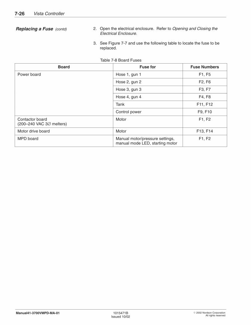
Vista Controller7-26
� 2002 Nordson CorporationAll rights reserved
1015471BIssued 10/02
Manual41-3700VMPD-MA-01
2. Open the electrical enclosure. Refer to Opening and Closing theElectrical Enclosure.
3. See Figure 7-7 and use the following table to locate the fuse to bereplaced.
Table 7-8 Board Fuses
Board Fuse for Fuse Numbers
Power board Hose 1, gun 1 F1, F5
Hose 2, gun 2 F2, F6
Hose 3, gun 3 F3, F7
Hose 4, gun 4 F4, F8
Tank F11, F12
Control power F9, F10
Contactor board(200–240 VAC 3∅ melters)
Motor F1, F2
Motor drive board Motor F13, F14
MPD board Manual motor/pressure settings,manual mode LED, starting motor
F1, F2
Replacing a Fuse (contd)
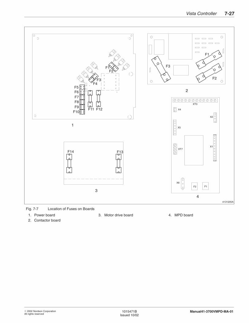
Vista Controller 7-27
� 2002 Nordson CorporationAll rights reserved
1015471BIssued 10/02
Manual41-3700VMPD-MA-01
4131205A
F1F2
F3F4
F5F6F7F8F9
F10F11 F12
1
2
F1
F2
F3
3
F14 F13
4
X2
X4
XT3
X6
X1
X5
XT7
F2 F1
Fig. 7-7 Location of Fuses on Boards
1. Power board2. Contactor board
3. Motor drive board 4. MPD board
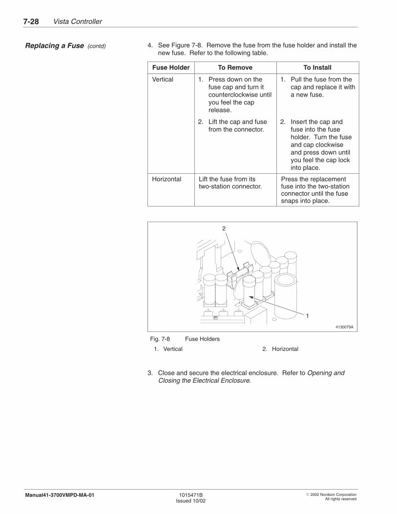
Vista Controller7-28
� 2002 Nordson CorporationAll rights reserved
1015471BIssued 10/02
Manual41-3700VMPD-MA-01
4. See Figure 7-8. Remove the fuse from the fuse holder and install thenew fuse. Refer to the following table.
Fuse Holder To Remove To Install
Vertical 1. Press down on thefuse cap and turn itcounterclockwise untilyou feel the caprelease.
1. Pull the fuse from thecap and replace it witha new fuse.
2. Lift the cap and fusefrom the connector.
2. Insert the cap andfuse into the fuseholder. Turn the fuseand cap clockwiseand press down untilyou feel the cap lockinto place.
Horizontal Lift the fuse from itstwo-station connector.
Press the replacementfuse into the two-stationconnector until the fusesnaps into place.
4130079A
2
1
Fig. 7-8 Fuse Holders
1. Vertical 2. Horizontal
3. Close and secure the electrical enclosure. Refer to Opening andClosing the Electrical Enclosure.
Replacing a Fuse (contd)
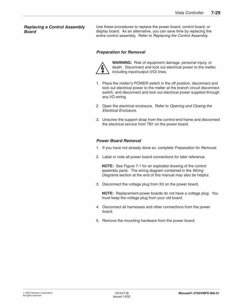
Vista Controller 7-29
� 2002 Nordson CorporationAll rights reserved
1015471BIssued 10/02
Manual41-3700VMPD-MA-01
Use these procedures to replace the power board, control board, ordisplay board. As an alternative, you can save time by replacing theentire control assembly. Refer to Replacing the Control Assembly.
Preparation for Removal
WARNING: Risk of equipment damage, personal injury, ordeath. Disconnect and lock out electrical power to the melter,including input/output (I/O) lines.
1. Place the melter’s POWER switch in the off position, disconnect andlock out electrical power to the melter at the branch circuit disconnectswitch, and disconnect and lock out electrical power supplied throughany I/O wiring.
2. Open the electrical enclosure. Refer to Opening and Closing theElectrical Enclosure.
3. Unscrew the support strap from the control-end frame and disconnectthe electrical service from TB1 on the power board.
Power Board Removal
1. If you have not already done so, complete Preparation for Removal.
2. Label or note all power board connections for later reference.
NOTE: See Figure 7-1 for an exploded drawing of the controlassembly parts. The wiring diagram contained in the WiringDiagrams section at the end of this manual may also be helpful.
3. Disconnect the voltage plug from X3 on the power board.
NOTE: Replacement power boards do not have a voltage plug. Youmust keep the voltage plug from your old board.
4. Disconnect all harnesses and other connections from the powerboard.
5. Remove the mounting hardware from the power board.
Replacing a Control AssemblyBoard
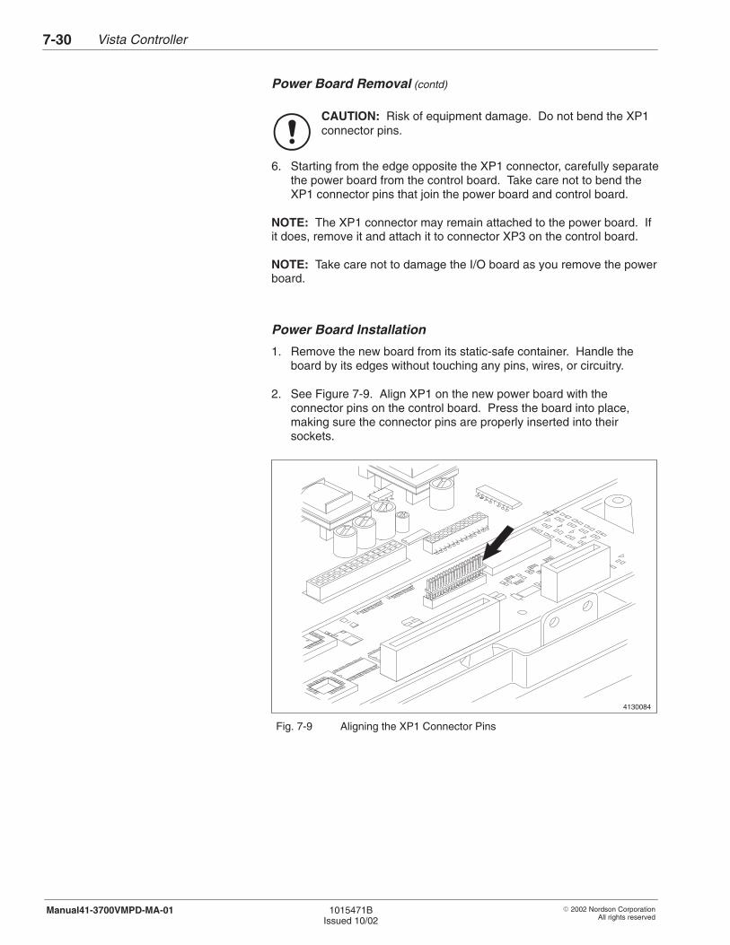
Vista Controller7-30
� 2002 Nordson CorporationAll rights reserved
1015471BIssued 10/02
Manual41-3700VMPD-MA-01
Power Board Removal (contd)
CAUTION: Risk of equipment damage. Do not bend the XP1connector pins.
6. Starting from the edge opposite the XP1 connector, carefully separatethe power board from the control board. Take care not to bend theXP1 connector pins that join the power board and control board.
NOTE: The XP1 connector may remain attached to the power board. Ifit does, remove it and attach it to connector XP3 on the control board.
NOTE: Take care not to damage the I/O board as you remove the powerboard.
Power Board Installation
1. Remove the new board from its static-safe container. Handle theboard by its edges without touching any pins, wires, or circuitry.
2. See Figure 7-9. Align XP1 on the new power board with theconnector pins on the control board. Press the board into place,making sure the connector pins are properly inserted into theirsockets.
4130084
1
Fig. 7-9 Aligning the XP1 Connector Pins
Vista Controller 7-31
� 2002 Nordson CorporationAll rights reserved
1015471BIssued 10/02
Manual41-3700VMPD-MA-01
3. Install the mounting screws and lock washers you removed earlier.Be sure to use lock washers on the three screws located at the threeground pads on the power board. Tighten all screws to1.1–1.4 N�m (10–12 in.-lb).
NOTE: See Figure 7-1 for an exploded drawing of the controlassembly parts.
4. Install the large triac (Q17) screw, which is to the left of TB1. Tightenthe screw to 0.3–0.5 N�m (3–4 in.-lb).
5. Install the two triac clamps and, starting with the center screw, tightenthe securing screws to 1.1–1.4 N�m (10–12 in.-lb).
6. Connect the voltage plug you kept from your old board to X3 on thepower board.
7. Connect all other harnesses and other connections to the powerboard.
8. Go to System Restoration.
Control Board Removal
1. If you have not already done so, complete Preparation for Removal.
2. Remove the power board. Refer to Power Board Removal.
3. Label or note all control board connections for later reference.
NOTE: See Figure 7-1 for an exploded drawing of the controlassembly parts. The wiring diagram contained in the Schematics section may also be helpful.
4. Disconnect all harnesses, and other connections from the controlboard.
5. Remove the mounting hardware from the control board.
6. Disconnect the I/O board from the control board.
7. Carefully separate the control board from the display board. Takecare not to bend the XP4A connector pins that join the control anddisplay boards. Retain the connector.
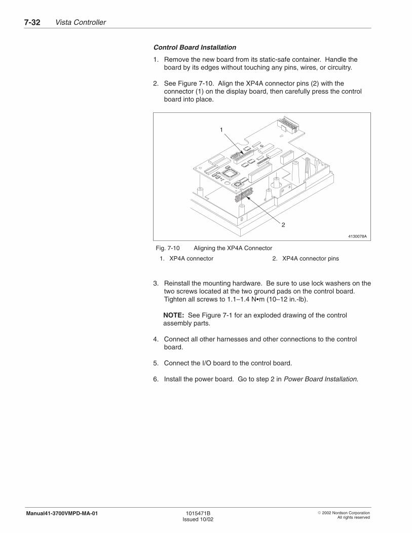
Vista Controller7-32
� 2002 Nordson CorporationAll rights reserved
1015471BIssued 10/02
Manual41-3700VMPD-MA-01
Control Board Installation
1. Remove the new board from its static-safe container. Handle theboard by its edges without touching any pins, wires, or circuitry.
2. See Figure 7-10. Align the XP4A connector pins (2) with the connector (1) on the display board, then carefully press the controlboard into place.
4130078A1
1
2
Fig. 7-10 Aligning the XP4A Connector
1. XP4A connector 2. XP4A connector pins
3. Reinstall the mounting hardware. Be sure to use lock washers on thetwo screws located at the two ground pads on the control board.Tighten all screws to 1.1–1.4 N�m (10–12 in.-lb).
NOTE: See Figure 7-1 for an exploded drawing of the controlassembly parts.
4. Connect all other harnesses and other connections to the controlboard.
5. Connect the I/O board to the control board.
6. Install the power board. Go to step 2 in Power Board Installation.
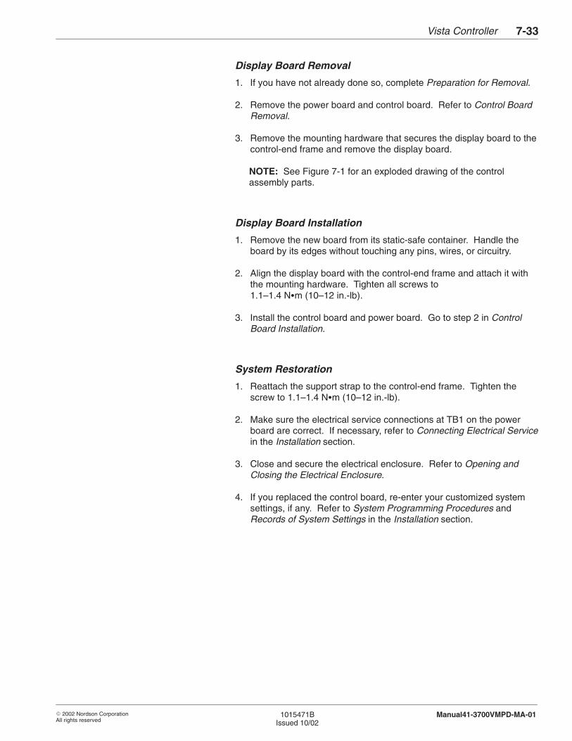
Vista Controller 7-33
� 2002 Nordson CorporationAll rights reserved
1015471BIssued 10/02
Manual41-3700VMPD-MA-01
Display Board Removal
1. If you have not already done so, complete Preparation for Removal.
2. Remove the power board and control board. Refer to Control BoardRemoval.
3. Remove the mounting hardware that secures the display board to thecontrol-end frame and remove the display board.
NOTE: See Figure 7-1 for an exploded drawing of the controlassembly parts.
Display Board Installation
1. Remove the new board from its static-safe container. Handle theboard by its edges without touching any pins, wires, or circuitry.
2. Align the display board with the control-end frame and attach it withthe mounting hardware. Tighten all screws to1.1–1.4 N�m (10–12 in.-lb).
3. Install the control board and power board. Go to step 2 in ControlBoard Installation.
System Restoration
1. Reattach the support strap to the control-end frame. Tighten thescrew to 1.1–1.4 N�m (10–12 in.-lb).
2. Make sure the electrical service connections at TB1 on the powerboard are correct. If necessary, refer to Connecting Electrical Servicein the Installation section.
3. Close and secure the electrical enclosure. Refer to Opening andClosing the Electrical Enclosure.
4. If you replaced the control board, re-enter your customized systemsettings, if any. Refer to System Programming Procedures andRecords of System Settings in the Installation section.
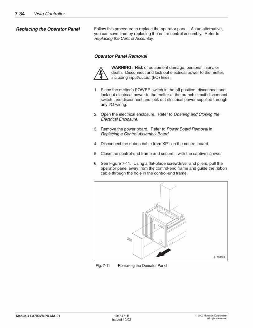
Vista Controller7-34
� 2002 Nordson CorporationAll rights reserved
1015471BIssued 10/02
Manual41-3700VMPD-MA-01
Follow this procedure to replace the operator panel. As an alternative,you can save time by replacing the entire control assembly. Refer toReplacing the Control Assembly.
Operator Panel Removal
WARNING: Risk of equipment damage, personal injury, ordeath. Disconnect and lock out electrical power to the melter,including input/output (I/O) lines.
1. Place the melter’s POWER switch in the off position, disconnect andlock out electrical power to the melter at the branch circuit disconnectswitch, and disconnect and lock out electrical power supplied throughany I/O wiring.
2. Open the electrical enclosure. Refer to Opening and Closing theElectrical Enclosure.
3. Remove the power board. Refer to Power Board Removal inReplacing a Control Assembly Board.
4. Disconnect the ribbon cable from XP1 on the control board.
5. Close the control-end frame and secure it with the captive screws.
6. See Figure 7-11. Using a flat-blade screwdriver and pliers, pull theoperator panel away from the control-end frame and guide the ribboncable through the hole in the control-end frame.
4130096A
Fig. 7-11 Removing the Operator Panel
Replacing the Operator Panel
Vista Controller 7-35
� 2002 Nordson CorporationAll rights reserved
1015471BIssued 10/02
Manual41-3700VMPD-MA-01
7. Use a citrus industrial cleaner to remove any adhesive that remainson the control-end frame; then use denatured alcohol to thoroughlyclean the residue left by the citrus industrial cleaner.
Operator Panel Installation
1. Remove the new operator panel from its static-safe container.Handle the panel by its edges without touching the ribbon cable pins.
2. With clean hands, peel the paper backing from the operator panel.Be sure to remove all the paper, especially around the ribbon cable.
3. See Figure 7-12. Connect the plastic ground tab, which is locatedbehind the Selector display, to the operator panel by lifting the tab upand pressing it against the adhesive backing.
4130099A
Fig. 7-12 Connecting the Ground Tab
4. Insert the ribbon cable through the hole in the control-end frame and,starting from the ribbon strip side of the operator panel, carefully alignthe operator panel on the control-end frame.
CAUTION: Mount the operator panel on a clean, smoothsurface. Otherwise, the panel may lose contact and cause poormelter performance. Additional damage can occur if operatorsattempt to run the melter using a panel that is not securelymounted.
5. Firmly press the panel into place with a rubber roller or similar tool.
6. Loosen the captive screws and lower the control-end frame. Connectthe ribbon cable to XP1 on the control board.
7. Install the power board, connect the electrical service, and close andsecure the electrical enclosure. Go to Power Board Installation andSystem Restoration in Replacing a Control Assembly Board.

Vista Controller7-36
� 2002 Nordson CorporationAll rights reserved
1015471BIssued 10/02
Manual41-3700VMPD-MA-01
Follow this procedure to replace the control assembly. The controlassembly includes the following components:
� power board� control board� display board� control-end frame� operator panel
Control Assembly Removal
WARNING: Risk of equipment damage, personal injury, ordeath. Disconnect and lock out electrical power to the melter,including input/output (I/O) lines.
1. Place the melter’s POWER switch in the off position, disconnect andlock out electrical power to the melter at the branch circuit disconnectswitch, and disconnect and lock out electrical power supplied throughany I/O wiring.
2. Open the electrical enclosure. Refer to Opening and Closing theElectrical Enclosure.
3. Disconnect the electrical service wiring from TB1 on the power boardand remove the wiring from the cable strap.
4. Disconnect the ground wire.
5. Taking care not to cut any electrical wires, cut the cable ties thatsecure the harnesses at the bottom of the control-end frame.
6. Disconnect the voltage plug from X3 on the power board.
NOTE: Replacement power boards do not have a voltage plug. Youmust keep the voltage plug from your old board.
7. Label or note all power board connections for later reference.
NOTE: See Figure 7-1 for an exploded drawing of the controlassembly parts. The wiring diagram contained in the Schematics section may also be helpful.
8. Disconnect all harnesses and other connections from the powerboard.
9. Disconnect the plug from XP2 on the control board.
Replacing the ControlAssembly
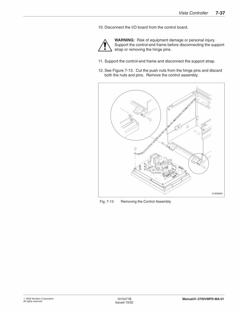
Vista Controller 7-37
� 2002 Nordson CorporationAll rights reserved
1015471BIssued 10/02
Manual41-3700VMPD-MA-01
10. Disconnect the I/O board from the control board.
WARNING: Risk of equipment damage or personal injury.Support the control-end frame before disconnecting the supportstrap or removing the hinge pins.
11. Support the control-end frame and disconnect the support strap.
12. See Figure 7-13. Cut the push nuts from the hinge pins and discardboth the nuts and pins. Remove the control assembly.
4130092A
+
ÎÎÎÎÎÎÎÎÎÎÎÎÎÎÎÎÎÎÎÎÎÎÎÎÎÎÎÎÎÎÎÎÎÎÎÎÎÎÎÎÎÎÎÎÎÎÎÎÎÎÎÎÎÎÎÎÎÎÎÎÎÎÎÎÎÎÎÎÎÎÎÎÎÎÎÎÎÎÎÎÎÎÎÎÎÎÎÎÎÎÎÎÎÎÎÎÎÎÎÎÎÎÎÎÎÎÎÎÎÎ
Fig. 7-13 Removing the Control Assembly

Vista Controller7-38
� 2002 Nordson CorporationAll rights reserved
1015471BIssued 10/02
Manual41-3700VMPD-MA-01
Control Assembly Installation
1. Remove the new control assembly from its static-safe container.Avoid touching any pins, wires, or circuitry.
2. Support the control-end frame, align the control assembly with thebase of the melter, and insert the new hinge pins through the holes inthe control-end frame and melter base. Install the pins so the head ofeach pin is on the outside of the front or rear panel.
3. Using an appropriate tool, press new push nuts over the hinge pins.
4. Reattach the support strap to the control-end frame. Tighten thescrew to 1.1–1.4 N�m (10–12 in.-lb).
5. Connect the XP2 plug to the control board.
6. Connect the I/O board to the control board.
7. Connect all other harnesses and other connections to the powerboard.
8. Connect the voltage plug you kept from your old board to X3 on thepower board.
9. Secure the electrical service wiring with the cable strap. Tighten thescrew to 2.48–2.93 N�m (22–26 in.-lb).
10. Connect the electrical service wiring. If necessary, refer toConnecting Electrical Service in the Installation section.
11. Secure the harnesses with new cable ties and secure the cable ties tothe bottom of the control-end frame.
12. Connect the ground wire.
13. Close and secure the electrical enclosure. Refer to Opening andClosing the Electrical Enclosure.
14. Re-enter your customized system settings, if any. Refer to SystemProgramming Procedures and Records of System Settings in theInstallation section.
Vista Controller 7-39
� 2002 Nordson CorporationAll rights reserved
1015471BIssued 10/02
Manual41-3700VMPD-MA-01
Your melter may include one or more melter-specific boards, dependingon the configuration of the melter. Instructions for replacingmelter-specific boards are supplied with the replacement board repairkits. Refer to the Parts section for the repair kit part numbers.
I/O Board Replacement
Use this procedure to replace a defective I/O board with a new I/O board.
WARNING: Risk of equipment damage, personal injury, ordeath. Disconnect and lock out electrical power to the melter,including input/output (I/O) lines.
1. Turn off the melter; then disconnect and lock out electrical power tothe melter, including I/O lines.
2. Open the electrical enclosure. Refer to Opening and Closing theElectrical Enclosure.
3. Remove the screw that holds the board to its bracket inside theelectrical enclosure.
NOTE: A new bracket is included in the service kit. If desired, youcan replace the existing bracket with this new bracket.
4. Label or note existing connections for later reference, then disconnectwires from the board and pull the board out of the XP5 card edgeconnector.
5. Remove the new board from its static-safe container, making sure tohandle the board by its edges without touching pins, wires, orcircuitry.
6. Carefully install the new board in the XP5 card edge connector andattach the board to the bracket with the screw provided in the servicekit. Tighten the screw to 1.1–1.4 N�m (10–12 in.-lb).
7. Reconnect wires to the new I/O board. Refer to Input/OutputConnections in the Installation section for terminal connections.
8. Close and secure the electrical enclosure. Refer to Opening andClosing the Electrical Enclosure.
9. Restore power to the melter and resume normal operation.
For wiring information, refer to the Schematics section.
Replacing a Melter-SpecificBoard
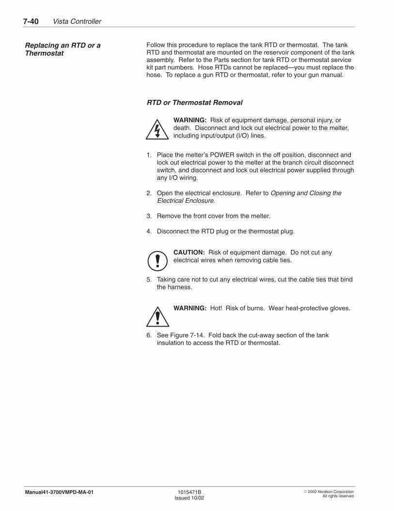
Vista Controller7-40
� 2002 Nordson CorporationAll rights reserved
1015471BIssued 10/02
Manual41-3700VMPD-MA-01
Follow this procedure to replace the tank RTD or thermostat. The tankRTD and thermostat are mounted on the reservoir component of the tankassembly. Refer to the Parts section for tank RTD or thermostat servicekit part numbers. Hose RTDs cannot be replaced—you must replace thehose. To replace a gun RTD or thermostat, refer to your gun manual.
RTD or Thermostat Removal
WARNING: Risk of equipment damage, personal injury, ordeath. Disconnect and lock out electrical power to the melter,including input/output (I/O) lines.
1. Place the melter’s POWER switch in the off position, disconnect andlock out electrical power to the melter at the branch circuit disconnectswitch, and disconnect and lock out electrical power supplied throughany I/O wiring.
2. Open the electrical enclosure. Refer to Opening and Closing theElectrical Enclosure.
3. Remove the front cover from the melter.
4. Disconnect the RTD plug or the thermostat plug.
CAUTION: Risk of equipment damage. Do not cut anyelectrical wires when removing cable ties.
5. Taking care not to cut any electrical wires, cut the cable ties that bindthe harness.
WARNING: Hot! Risk of burns. Wear heat-protective gloves.
6. See Figure 7-14. Fold back the cut-away section of the tankinsulation to access the RTD or thermostat.
Replacing an RTD or aThermostat
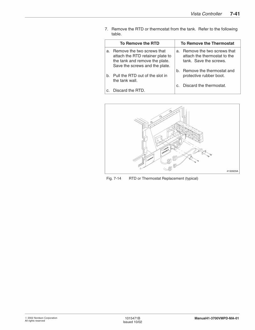
Vista Controller 7-41
� 2002 Nordson CorporationAll rights reserved
1015471BIssued 10/02
Manual41-3700VMPD-MA-01
7. Remove the RTD or thermostat from the tank. Refer to the followingtable.
To Remove the RTD To Remove the Thermostat
a. Remove the two screws thatattach the RTD retainer plate tothe tank and remove the plate.Save the screws and the plate.
b. Pull the RTD out of the slot inthe tank wall.
c. Discard the RTD.
a. Remove the two screws thatattach the thermostat to thetank. Save the screws.
b. Remove the thermostat andprotective rubber boot.
c. Discard the thermostat.
4130929A
ÏÏÏÏÏÏÏÏÏÏÏÏÏÏÏ
ÎÎÎÎÎÎÎÎÎÎÎÎÎÎÎÎÎÎÎÎ
ÏÏÏÏÏÏÏÏÏÏÏÏÏÏÏÏÏÏÏÏÏÏÏÏÏ
ÏÏ
ÏÏÏÏÏÏÏÏÏÏÏÏÏÏÏÏÏÏÏÏÏÏÏÏ
Fig. 7-14 RTD or Thermostat Replacement (typical)
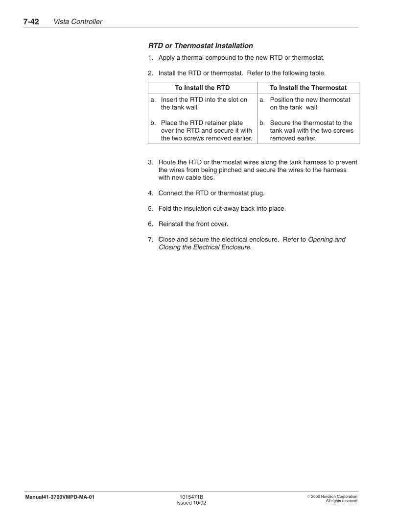
Vista Controller7-42
� 2002 Nordson CorporationAll rights reserved
1015471BIssued 10/02
Manual41-3700VMPD-MA-01
RTD or Thermostat Installation
1. Apply a thermal compound to the new RTD or thermostat.
2. Install the RTD or thermostat. Refer to the following table.
To Install the RTD To Install the Thermostat
a. Insert the RTD into the slot onthe tank wall.
b. Place the RTD retainer plateover the RTD and secure it withthe two screws removed earlier.
a. Position the new thermostaton the tank wall.
b. Secure the thermostat to thetank wall with the two screwsremoved earlier.
3. Route the RTD or thermostat wires along the tank harness to preventthe wires from being pinched and secure the wires to the harnesswith new cable ties.
4. Connect the RTD or thermostat plug.
5. Fold the insulation cut-away back into place.
6. Reinstall the front cover.
7. Close and secure the electrical enclosure. Refer to Opening andClosing the Electrical Enclosure.

� 2002 Nordson CorporationAll rights reserved
1015471BIssued 10/02
Manual41-3700VMPD-MA-01
Section 8
Hydraulics

Hydraulics8-0
� 2002 Nordson CorporationAll rights reserved
1015471BIssued 10/02
Manual41-3700VMPD-MA-01
Hydraulics 8-1
� 2002 Nordson CorporationAll rights reserved
1015471BIssued 10/02
Manual41-3700VMPD-MA-01
Section 8Hydraulics
WARNING: Allow only qualified personnel to perform thefollowing tasks. Follow the safety instructions in this documentand all other related documentation.
This section includes troubleshooting procedures for adhesive applicationproblems and pump troubleshooting procedures and repair procedures.Refer to the Parts section for the part number of any pump componentthat needs to be replaced. If you try all the suggestions in this sectionand still cannot solve the problem, call your Nordson representative forassistance.
Refer to the Control System section for troubleshooting procedures andrepair procedures for the melter’s control system. For hose or guntroubleshooting, refer to your hose or gun manual.
The following sections of this manual contain additional information onthe hydraulic system:
� Technical Data includes pump specifications.
� Maintenance includes a procedure for checking the pump motorspeed reducer.
� Tank and Manifold includes procedures for replacing the tank,manifold, drain valve, pressure relief valve, circulation controlvalve, and pressure control valve.
1. Introduction

Hydraulics8-2
� 2002 Nordson CorporationAll rights reserved
1015471BIssued 10/02
Manual41-3700VMPD-MA-01
These troubleshooting tables describe the kinds of adhesive applicationand pump-operation problems you may encounter and provide correctiveactions for handling those problems. When necessary, the tables refer tomore detailed diagnostic procedures. Refer to the appropriatetroubleshooting table for the type of problem you are experiencing:
� Adhesive Not Applying Properly� Pump or Motor Not Working
Problem Possible Cause Corrective Action
1. Little or no adhesive output Melter not at operating temperature Wait for the time delay to expire andthe SYSTEM READY light to turn on.
Adhesive level too low Keep the tank at least half full ofadhesive. Refer to Adhesive Filling inthe Operation section.
Adhesive too cold Check the tank, hose, or gunoperating temperature setpoints andadjust them as necessary.
Motor speed and/or pressure controlnot properly set
Check OEM signals to motor andpressure control
Clogged manifold filter Clean the manifold filter. Refer toCleaning a Manifold Filter in theMaintenance section.
Blockage in manifold Check for blockage. Refer toManifold Blockage Check.
Circulation control valve or pressurecontrol valve not properly set orclogged
Check the circulation control orpressure control valve. Refer tosystem flushing procedure in theInstallation section to set up thevalve.
Cold hose-to-melter or hose-to-gunjoints
Insulate the joints.
Guns not operating properly Refer to the gun manual totroubleshoot gun problems.
Manifold heat exchanger blocked Check manifold heat exchanger forblockage. Clean if necessary.
Filter set to DRAIN mode Change filter setting to RUN
2. Troubleshooting Tables
Adhesive Not ApplyingProperly
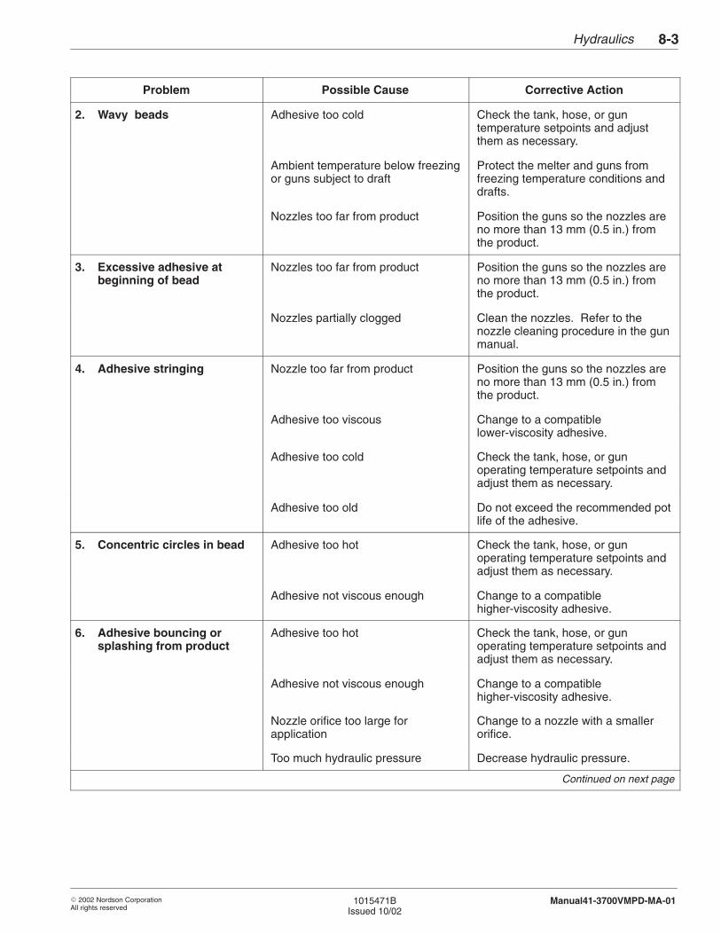
Hydraulics 8-3
� 2002 Nordson CorporationAll rights reserved
1015471BIssued 10/02
Manual41-3700VMPD-MA-01
Problem Possible Cause Corrective Action
2. Wavy beads Adhesive too cold Check the tank, hose, or guntemperature setpoints and adjustthem as necessary.
Ambient temperature below freezingor guns subject to draft
Protect the melter and guns fromfreezing temperature conditions anddrafts.
Nozzles too far from product Position the guns so the nozzles areno more than 13 mm (0.5 in.) fromthe product.
3. Excessive adhesive atbeginning of bead
Nozzles too far from product Position the guns so the nozzles areno more than 13 mm (0.5 in.) fromthe product.
Nozzles partially clogged Clean the nozzles. Refer to thenozzle cleaning procedure in the gunmanual.
4. Adhesive stringing Nozzle too far from product Position the guns so the nozzles areno more than 13 mm (0.5 in.) fromthe product.
Adhesive too viscous Change to a compatiblelower-viscosity adhesive.
Adhesive too cold Check the tank, hose, or gunoperating temperature setpoints andadjust them as necessary.
Adhesive too old Do not exceed the recommended potlife of the adhesive.
5. Concentric circles in bead Adhesive too hot Check the tank, hose, or gunoperating temperature setpoints andadjust them as necessary.
Adhesive not viscous enough Change to a compatiblehigher-viscosity adhesive.
6. Adhesive bouncing orsplashing from product
Adhesive too hot Check the tank, hose, or gunoperating temperature setpoints andadjust them as necessary.
Adhesive not viscous enough Change to a compatiblehigher-viscosity adhesive.
Nozzle orifice too large forapplication
Change to a nozzle with a smallerorifice.
Too much hydraulic pressure Decrease hydraulic pressure.
Continued on next page
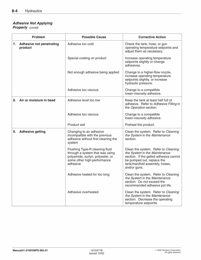
Hydraulics8-4
� 2002 Nordson CorporationAll rights reserved
1015471BIssued 10/02
Manual41-3700VMPD-MA-01
Problem Possible Cause Corrective Action
7. Adhesive not penetratingproduct
Adhesive too cold Check the tank, hose, or gunoperating temperature setpoints andadjust them as necessary.
Special coating on product Increase operating temperaturesetpoints slightly or changeadhesives.
Not enough adhesive being applied Change to a higher-flow nozzle,increase operating temperaturesetpoints slightly, or increasehydraulic pressure.
Adhesive too viscous Change to a compatiblelower-viscosity adhesive.
8. Air or moisture in bead Adhesive level too low Keep the tank at least half full ofadhesive. Refer to Adhesive Filling inthe Operation section.
Adhesive too viscous Change to a compatiblelower-viscosity adhesive.
Product wet Preheat the product.
9. Adhesive gelling Changing to an adhesiveincompatible with the previousadhesive without first cleaning thesystem
Clean the system. Refer to Cleaningthe System in the Maintenancesection.
Flushing Type-R cleaning fluidthrough a system that was usingpolyamide, surlyn, polyester, orsome other high-performanceadhesive
Clean the system. Refer to Cleaningthe System in the Maintenancesection. If the gelled adhesive cannotbe pumped out, replace thetank/manifold assembly, hoses,and/or guns.
Adhesive heated for too long Clean the system. Refer to Cleaningthe System in the Maintenancesection. Do not exceed therecommended adhesive pot life.
Adhesive overheated Clean the system. Refer to Cleaningthe System in the Maintenancesection. Decrease the operatingtemperature setpoints.
Adhesive Not ApplyingProperly (contd)
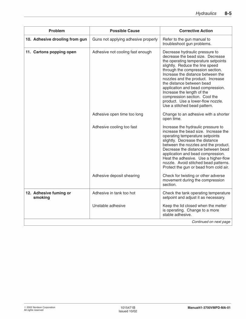
Hydraulics 8-5
� 2002 Nordson CorporationAll rights reserved
1015471BIssued 10/02
Manual41-3700VMPD-MA-01
Problem Corrective ActionPossible Cause
10. Adhesive drooling from gun Guns not applying adhesive properly Refer to the gun manual totroubleshoot gun problems.
11. Cartons popping open Adhesive not cooling fast enough Decrease hydraulic pressure todecrease the bead size. Decreasethe operating temperature setpointsslightly. Reduce the line speedthrough the compression section.Increase the distance between thenozzles and the product. Increasethe distance between beadapplication and bead compression.Increase the length of thecompression section. Cool theproduct. Use a lower-flow nozzle.Use a stitched bead pattern.
Adhesive open time too long Change to an adhesive with a shorteropen time.
Adhesive cooling too fast Increase the hydraulic pressure toincrease the bead size. Increase theoperating temperature setpointsslightly. Decrease the distancebetween the nozzles and the product.Decrease the distance between beadapplication and bead compression.Heat the adhesive. Use a higher-flownozzle. Avoid stitched bead patterns.Protect the gun or bead from cold air.
Adhesive deposit shearing Check for twisting or other adversemovement during the compressionsection.
12. Adhesive fuming orsmoking
Adhesive in tank too hot Check the tank operating temperaturesetpoint and adjust it as necessary.
Unstable adhesive Keep the lid closed when the melteris operating. Change to a morestable adhesive.
Continued on next page

Hydraulics8-6
� 2002 Nordson CorporationAll rights reserved
1015471BIssued 10/02
Manual41-3700VMPD-MA-01
Problem Possible Cause Corrective Action
13. Adhesive charring in tank Adhesive in tank too hot Check the tank operating temperaturesetpoint and adjust it as necessary.
Tank overheating Refer to the troubleshooting tables inthe Control System section.
Adhesive level too low Keep the tank at least half full ofadhesive. Refer to Adhesive Filling inthe Operation section.
Adhesive oxidizing in tank Keep the lid closed when the melteris operating. Change to a morestable adhesive. Switch to a melterwith a nitrogen blanket.
Adhesive Not ApplyingProperly (contd)
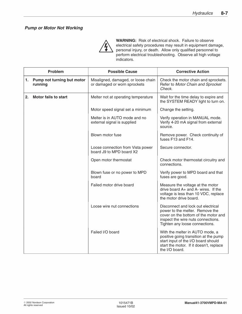
Hydraulics 8-7
� 2002 Nordson CorporationAll rights reserved
1015471BIssued 10/02
Manual41-3700VMPD-MA-01
WARNING: Risk of electrical shock. Failure to observeelectrical safety procedures may result in equipment damage,personal injury, or death. Allow only qualified personnel toperform electrical troubleshooting. Observe all high voltageindicators.
Problem Possible Cause Corrective Action
1. Pump not turning but motorrunning
Misaligned, damaged, or loose chainor damaged or worn sprockets
Check the motor chain and sprockets.Refer to Motor Chain and SprocketCheck.
2. Motor fails to start Melter not at operating temperature Wait for the time delay to expire andthe SYSTEM READY light to turn on.
Motor speed signal set a minimum Change the setting.
Melter is in AUTO mode and noexternal signal is supplied
Verify operation in MANUAL mode.Verify 4-20 mA signal from externalsource.
Blown motor fuse Remove power. Check continuity offuses F13 and F14.
Loose connection from Vista powerboard J9 to MPD board X2
Secure connector.
Open motor thermostat Check motor thermostat circuitry andconnections.
Blown fuse or no power to MPDboard
Verify power to MPD board and thatfuses are good.
Failed motor drive board Measure the voltage at the motordrive board A+ and A- wires. If thevoltage is less than 10 VDC, replacethe motor drive board.
Loose wire nut connections Disconnect and lock out electricalpower to the melter. Remove thecover on the bottom of the motor andinspect the wire nuts connections.Tighten any loose connections.
Failed I/O board With the melter in AUTO mode, apositive going transition at the pumpstart input of the I/O board shouldstart the motor. If it doesn’t, replacethe I/O board.
Pump or Motor Not Working

Hydraulics8-8
� 2002 Nordson CorporationAll rights reserved
1015471BIssued 10/02
Manual41-3700VMPD-MA-01
Use these procedures as directed by the troubleshooting tables to furthertroubleshoot pump-operation problems.
Motor Chain and Sprocket Check
1. Remove the drive cover.
2. Check the chain and sprocket:
� Chain misaligned or sprocket worn: realign the chain or replacethe sprocket.
� Chain and sprocket okay: continue to the next step.
3. Disassemble the chain by taking out the removable chain link. Jogthe pump motor and see if the speed reducer output shaft rotates.
� Shaft does not rotate: Replace the speed reducer.
� Shaft rotates: continue to the next step.
4. Manually rotate the sprocket above the gear pump by pulling on thechain.
� Drive shaft does not rotate: drain the tank so the adhesive level islower than the pump mount. Remove the pump. Manually rotatethe sprocket. If the sprocket rotates, replace the pump. If thesprocket does not rotate, replace the bearings and pack withgrease.
� Drive shaft rotates: drain the tank so the adhesive level is lowerthan the pump mount. Remove the pump. Check the drive shaftcoupling. If the coupling is worn or damaged, replace it. If thecoupling is okay, replace the pump.
Troubleshooting Procedures
Hydraulics 8-9
� 2002 Nordson CorporationAll rights reserved
1015471BIssued 10/02
Manual41-3700VMPD-MA-01
Manifold Blockage Check
1. Stop the pump.
2. With the manifold filter in the RUN position, open the right-side drainvalve.
3. Start the pump.
� Adhesive flows: filter is clear and manifold is not blocked. Returnto the troubleshooting table.
� Adhesive does not flow: manifold may be blocked. Turn thepump off and remove the manifold filter. Check for blockage inthe manifold and remove any blockage. Clean the manifold filter ifnecessary. Refer to Cleaning a Manifold Filter in the Maintenancesection.
Use these procedures to replace the pump, to replace any pumpcomponent, or to clean pump components. Refer to the Parts section forthe part numbers of any components that need to be replaced. You canalso use the parts list illustration as a guide as you perform the followingprocedures.
Follow this procedure to safely prepare for pump repairs.
1. Make sure the melter is at operating temperature.
2. Make sure the adhesive level in the hopper is lower than the pumpcavity.
3. Relieve hydraulic pressure. Refer to Relieving Hydraulic Pressure inthe Maintenance section.
4. Place the melter power switch in the OFF position, disconnect andlock out electrical power to the melter at the branch circuit disconnectswitch, and disconnect and lock out electrical power supplied throughany I/O wiring.
3. Pump Procedures
Preparing for Repairs
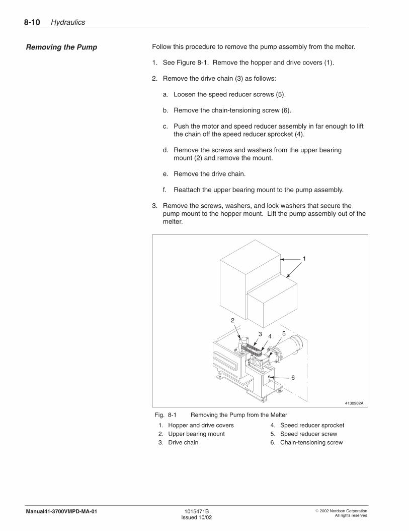
Hydraulics8-10
� 2002 Nordson CorporationAll rights reserved
1015471BIssued 10/02
Manual41-3700VMPD-MA-01
Follow this procedure to remove the pump assembly from the melter.
1. See Figure 8-1. Remove the hopper and drive covers (1).
2. Remove the drive chain (3) as follows:
a. Loosen the speed reducer screws (5).
b. Remove the chain-tensioning screw (6).
c. Push the motor and speed reducer assembly in far enough to liftthe chain off the speed reducer sprocket (4).
d. Remove the screws and washers from the upper bearingmount (2) and remove the mount.
e. Remove the drive chain.
f. Reattach the upper bearing mount to the pump assembly.
3. Remove the screws, washers, and lock washers that secure thepump mount to the hopper mount. Lift the pump assembly out of themelter.
4130902A
1
6
4
2
53
1
Fig. 8-1 Removing the Pump from the Melter
1. Hopper and drive covers2. Upper bearing mount3. Drive chain
4. Speed reducer sprocket5. Speed reducer screw6. Chain-tensioning screw
Removing the Pump
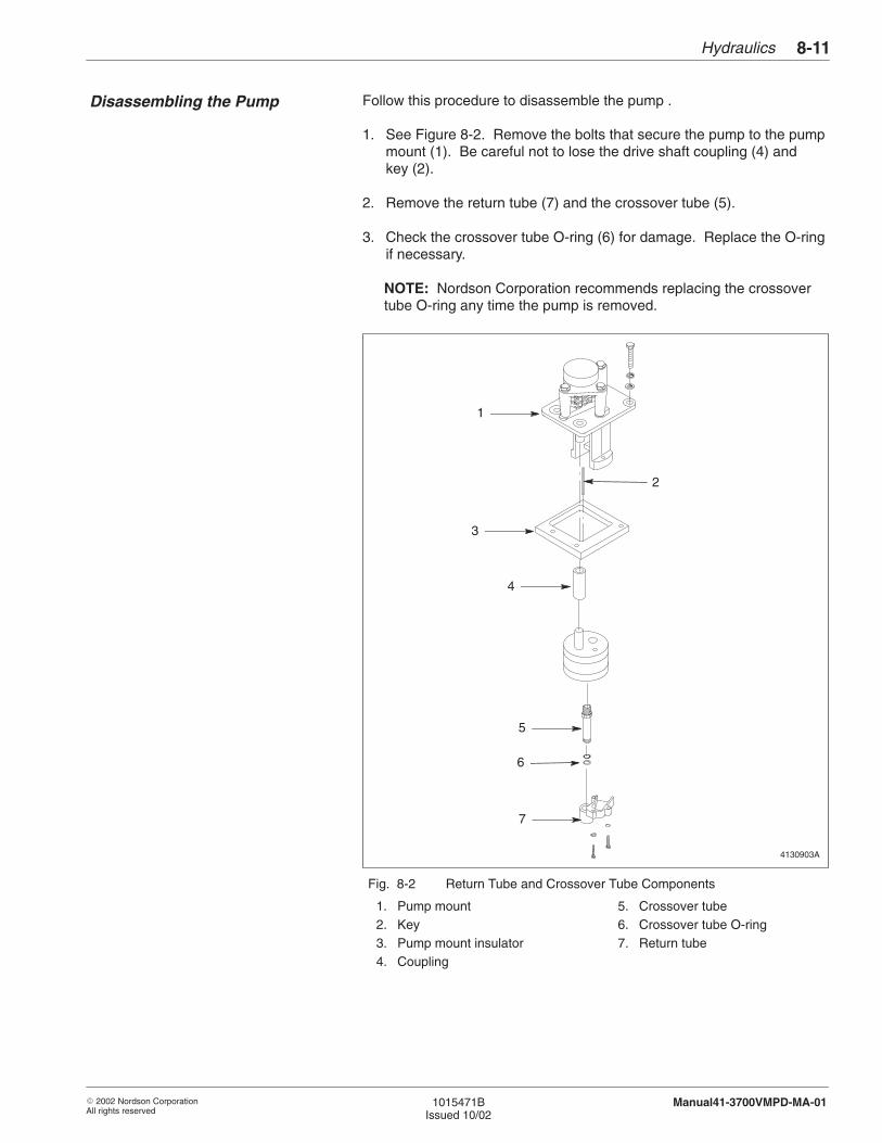
Hydraulics 8-11
� 2002 Nordson CorporationAll rights reserved
1015471BIssued 10/02
Manual41-3700VMPD-MA-01
Follow this procedure to disassemble the pump .
1. See Figure 8-2. Remove the bolts that secure the pump to the pumpmount (1). Be careful not to lose the drive shaft coupling (4) andkey (2).
2. Remove the return tube (7) and the crossover tube (5).
3. Check the crossover tube O-ring (6) for damage. Replace the O-ringif necessary.
NOTE: Nordson Corporation recommends replacing the crossovertube O-ring any time the pump is removed.
4130903A
3
4
6
7
1
5
2
Fig. 8-2 Return Tube and Crossover Tube Components
1. Pump mount2. Key3. Pump mount insulator4. Coupling
5. Crossover tube6. Crossover tube O-ring7. Return tube
Disassembling the Pump
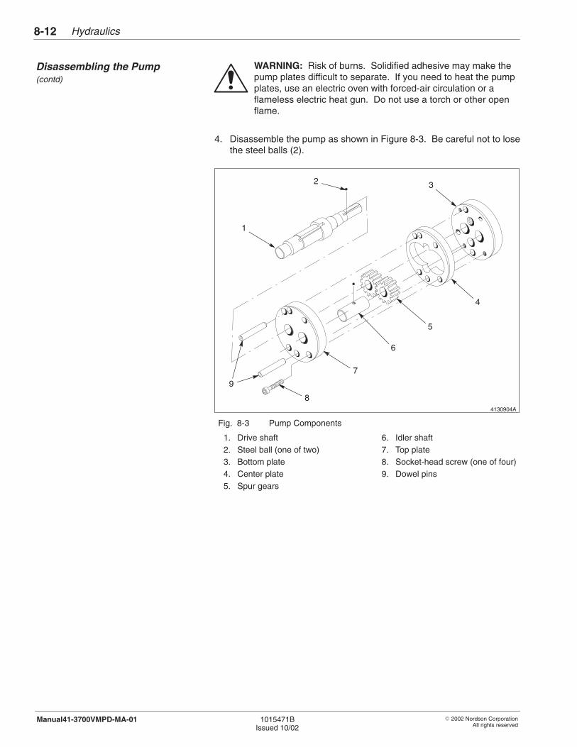
Hydraulics8-12
� 2002 Nordson CorporationAll rights reserved
1015471BIssued 10/02
Manual41-3700VMPD-MA-01
WARNING: Risk of burns. Solidified adhesive may make thepump plates difficult to separate. If you need to heat the pumpplates, use an electric oven with forced-air circulation or aflameless electric heat gun. Do not use a torch or other openflame.
4. Disassemble the pump as shown in Figure 8-3. Be careful not to losethe steel balls (2).
4130904A
1
2 3
4
6
7
8
5
9
Fig. 8-3 Pump Components
1. Drive shaft2. Steel ball (one of two)3. Bottom plate4. Center plate5. Spur gears
6. Idler shaft7. Top plate8. Socket-head screw (one of four)9. Dowel pins
Disassembling the Pump (contd)
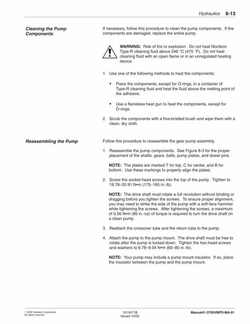
Hydraulics 8-13
� 2002 Nordson CorporationAll rights reserved
1015471BIssued 10/02
Manual41-3700VMPD-MA-01
If necessary, follow this procedure to clean the pump components. If thecomponents are damaged, replace the entire pump.
WARNING: Risk of fire or explosion. Do not heat NordsonType-R cleaning fluid above 246 °C (475 °F). Do not heatcleaning fluid with an open flame or in an unregulated heatingdevice.
1. Use one of the following methods to heat the components:
� Place the components, except for O-rings, in a container ofType-R cleaning fluid and heat the fluid above the melting point ofthe adhesive.
� Use a flameless heat gun to heat the components, except forO-rings.
2. Scrub the components with a fine-bristled brush and wipe them with aclean, dry cloth.
Follow this procedure to reassemble the gear pump assembly.
1. Reassemble the pump components. See Figure 8-3 for the properplacement of the shafts, gears, balls, pump plates, and dowel pins.
NOTE: The plates are marked T for top, C for center, and B forbottom. Use these markings to properly align the plates.
2. Screw the socket-head screws into the top of the pump. Tighten to19.78–20.91 N�m (175–185 in.-lb).
NOTE: The drive shaft must rotate a full revolution without binding ordragging before you tighten the screws. To ensure proper alignment,you may need to strike the side of the pump with a soft-face hammerwhile tightening the screws. After tightening the screws, a maximumof 0.56 N�m (80 in.-oz) of torque is required to turn the drive shaft ona clean pump.
3. Reattach the crossover tube and the return tube to the pump.
4. Attach the pump to the pump mount. The drive shaft must be free torotate after the pump is locked down. Tighten the hex-head screwsand washers to 6.78–9.04 N�m (60–80 in.-lb).
NOTE: Your pump may include a pump mount insulator. If so, placethe insulator between the pump and the pump mount.
Cleaning the PumpComponents
Reassembling the Pump
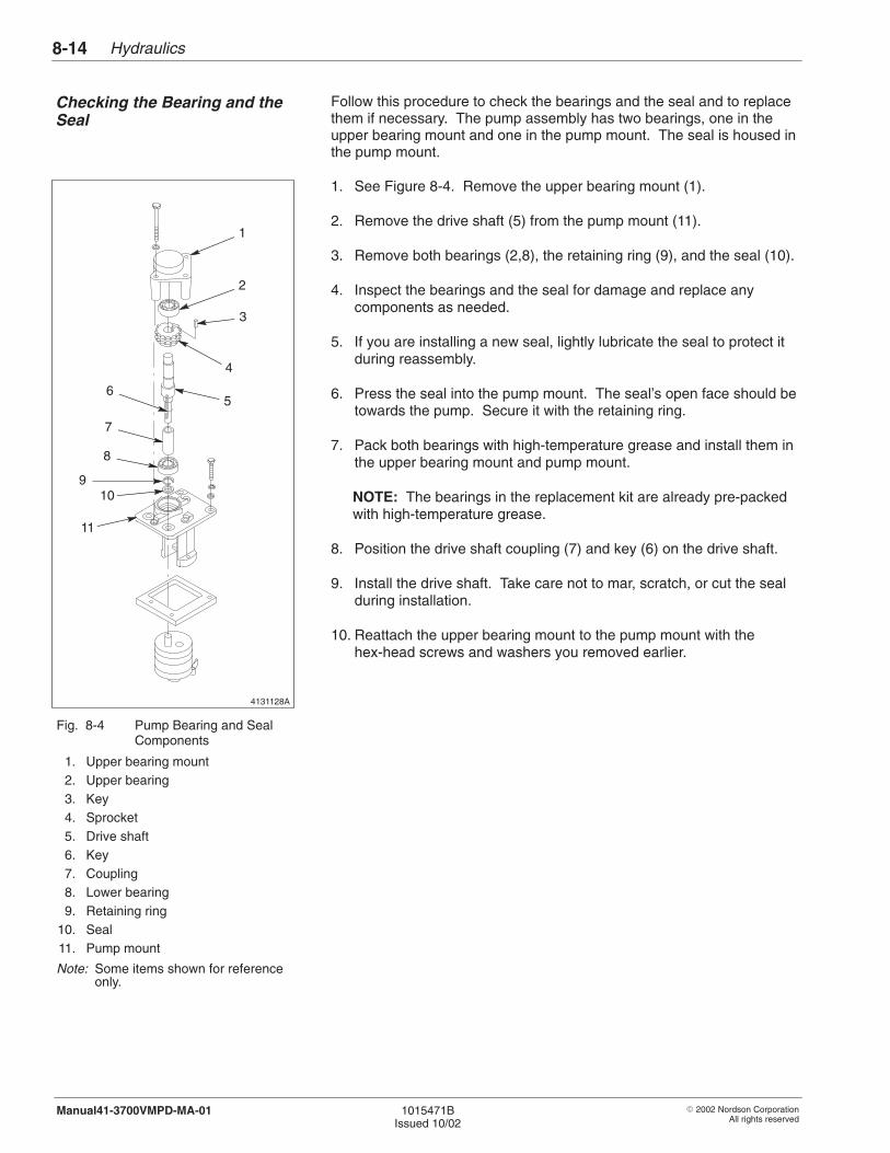
4131128A
1
2
3
4
56
7
8
11
910
Hydraulics8-14
� 2002 Nordson CorporationAll rights reserved
1015471BIssued 10/02
Manual41-3700VMPD-MA-01
Follow this procedure to check the bearings and the seal and to replacethem if necessary. The pump assembly has two bearings, one in theupper bearing mount and one in the pump mount. The seal is housed inthe pump mount.
1. See Figure 8-4. Remove the upper bearing mount (1).
2. Remove the drive shaft (5) from the pump mount (11).
3. Remove both bearings (2,8), the retaining ring (9), and the seal (10).
4. Inspect the bearings and the seal for damage and replace anycomponents as needed.
5. If you are installing a new seal, lightly lubricate the seal to protect itduring reassembly.
6. Press the seal into the pump mount. The seal’s open face should betowards the pump. Secure it with the retaining ring.
7. Pack both bearings with high-temperature grease and install them inthe upper bearing mount and pump mount.
NOTE: The bearings in the replacement kit are already pre-packedwith high-temperature grease.
8. Position the drive shaft coupling (7) and key (6) on the drive shaft.
9. Install the drive shaft. Take care not to mar, scratch, or cut the sealduring installation.
10. Reattach the upper bearing mount to the pump mount with thehex-head screws and washers you removed earlier.
Fig. 8-4 Pump Bearing and SealComponents
1. Upper bearing mount2. Upper bearing3. Key4. Sprocket5. Drive shaft6. Key7. Coupling8. Lower bearing9. Retaining ring
10. Seal11. Pump mount
Note: Some items shown for referenceonly.
Checking the Bearing and theSeal
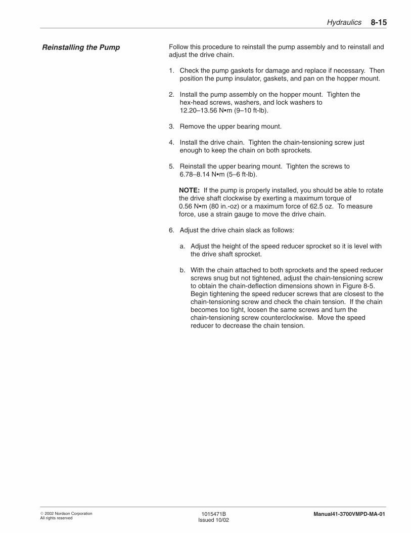
Hydraulics 8-15
� 2002 Nordson CorporationAll rights reserved
1015471BIssued 10/02
Manual41-3700VMPD-MA-01
Follow this procedure to reinstall the pump assembly and to reinstall andadjust the drive chain.
1. Check the pump gaskets for damage and replace if necessary. Thenposition the pump insulator, gaskets, and pan on the hopper mount.
2. Install the pump assembly on the hopper mount. Tighten thehex-head screws, washers, and lock washers to12.20–13.56 N�m (9–10 ft-lb).
3. Remove the upper bearing mount.
4. Install the drive chain. Tighten the chain-tensioning screw justenough to keep the chain on both sprockets.
5. Reinstall the upper bearing mount. Tighten the screws to6.78–8.14 N�m (5–6 ft-lb).
NOTE: If the pump is properly installed, you should be able to rotatethe drive shaft clockwise by exerting a maximum torque of0.56 N�m (80 in.-oz) or a maximum force of 62.5 oz. To measureforce, use a strain gauge to move the drive chain.
6. Adjust the drive chain slack as follows:
a. Adjust the height of the speed reducer sprocket so it is level withthe drive shaft sprocket.
b. With the chain attached to both sprockets and the speed reducerscrews snug but not tightened, adjust the chain-tensioning screwto obtain the chain-deflection dimensions shown in Figure 8-5.Begin tightening the speed reducer screws that are closest to thechain-tensioning screw and check the chain tension. If the chainbecomes too tight, loosen the same screws and turn thechain-tensioning screw counterclockwise. Move the speedreducer to decrease the chain tension.
Reinstalling the Pump
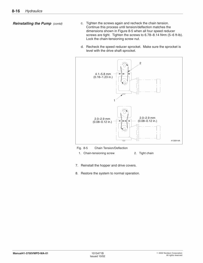
Hydraulics8-16
� 2002 Nordson CorporationAll rights reserved
1015471BIssued 10/02
Manual41-3700VMPD-MA-01
c. Tighten the screws again and recheck the chain tension.Continue this process until tension/deflection matches thedimensions shown in Figure 8-5 when all four speed reducerscrews are tight. Tighten the screws to 6.78–8.14 N�m (5–6 ft-lb).Lock the chain-tensioning screw nut.
d. Recheck the speed reducer sprocket. Make sure the sprocket islevel with the drive shaft sprocket.
4130914A
1
2
4.1–5.8 mm(0.16–1.23 in.)
2.0–2.9 mm(0.08–0.12 in.)
2.0–2.9 mm(0.08–0.12 in.)
Fig. 8-5 Chain Tension/Deflection
1. Chain-tensioning screw 2. Tight chain
7. Reinstall the hopper and drive covers.
8. Restore the system to normal operation.
Reinstalling the Pump (contd)
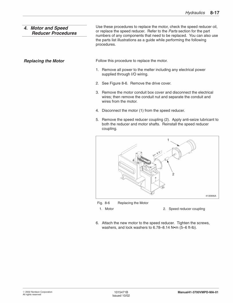
Hydraulics 8-17
� 2002 Nordson CorporationAll rights reserved
1015471BIssued 10/02
Manual41-3700VMPD-MA-01
Use these procedures to replace the motor, check the speed reducer oil,or replace the speed reducer. Refer to the Parts section for the partnumbers of any components that need to be replaced. You can also usethe parts list illustrations as a guide while performing the followingprocedures.
Follow this procedure to replace the motor.
1. Remove all power to the melter including any electrical powersupplied through I/O wiring.
2. See Figure 8-6. Remove the drive cover.
3. Remove the motor conduit box cover and disconnect the electricalwires; then remove the conduit nut and separate the conduit andwires from the motor.
4. Disconnect the motor (1) from the speed reducer.
5. Remove the speed reducer coupling (2). Apply anti-seize lubricant toboth the reducer and motor shafts. Reinstall the speed reducercoupling.
4130906A
2
1
Fig. 8-6 Replacing the Motor
1. Motor 2. Speed reducer coupling
6. Attach the new motor to the speed reducer. Tighten the screws,washers, and lock washers to 6.78–8.14 N�m (5–6 ft-lb).
4. Motor and SpeedReducer Procedures
Replacing the Motor
Hydraulics8-18
� 2002 Nordson CorporationAll rights reserved
1015471BIssued 10/02
Manual41-3700VMPD-MA-01
7. Attach the conduit to the motor conduit box. Refer to the Schematicssection for wiring diagrams.
8. Reinstall the motor conduit box cover.
9. Reinstall the drive cover.
10. Restore the system to normal operation.
Follow this procedure to replace the speed reducer.
Speed Reducer Removal
1. Remove all power to the melter including any electrical powersupplied through I/O wiring.
2. See Figure 8-7. Remove the drive cover.
3. Disconnect the motor (1) from the speed reducer (6). Do not hangthe motor by its conduit.
4. Remove the chain-tensioning screw and nut (10) and the four speedreducer screws (7) to separate the speed reducer from the spacers (8), the motor support bracket (9), and the adjusting bracket (11).
5. Remove the drive chain (3) from the speed reducer sprocket (4).
6. Remove the speed reducer sprocket and key (5). Do not remove thecoupling (2) from the speed reducer.
7. Remove the speed reducer and attached coupling from the melter.
Replacing the Motor (contd)
Replacing the Speed Reducer
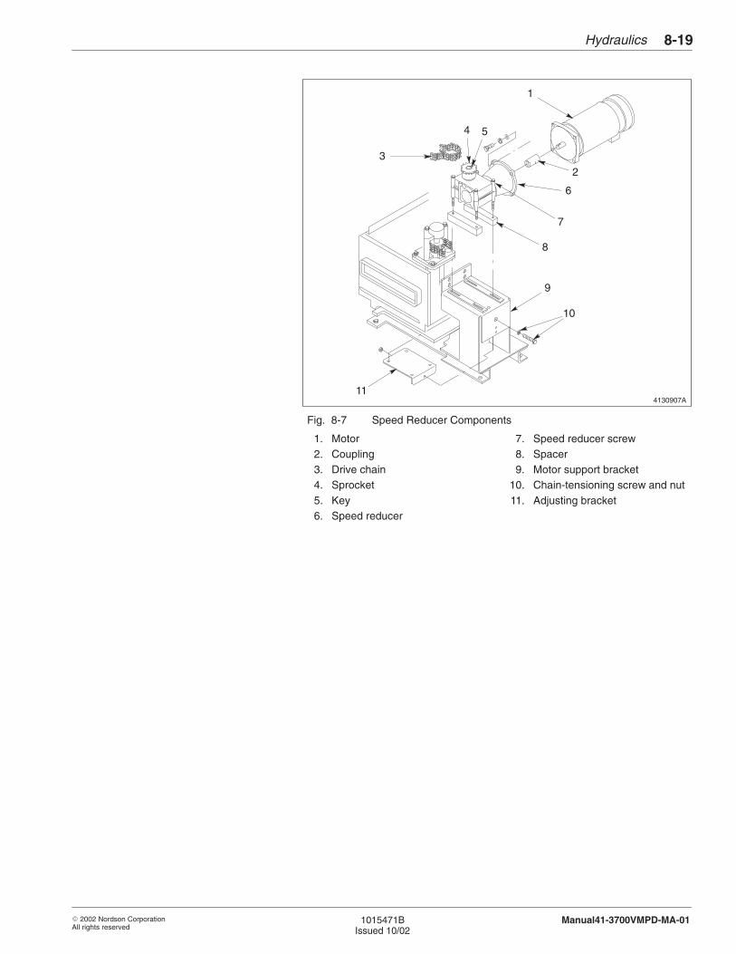
Hydraulics 8-19
� 2002 Nordson CorporationAll rights reserved
1015471BIssued 10/02
Manual41-3700VMPD-MA-01
4130907A
1
2
4
3
9
8
7
6
10
5
11
Fig. 8-7 Speed Reducer Components
1. Motor2. Coupling3. Drive chain4. Sprocket5. Key6. Speed reducer
7. Speed reducer screw8. Spacer9. Motor support bracket
10. Chain-tensioning screw and nut11. Adjusting bracket

Hydraulics8-20
� 2002 Nordson CorporationAll rights reserved
1015471BIssued 10/02
Manual41-3700VMPD-MA-01
Speed Reducer Installation
1. Attach the sprocket and the key to the new speed reducer.
2. The speed reducer replacement kit has two sets of screws. Removethe screws and nuts from the new reducer and discard them. Insertthe longer screws in the replacement kit in the new speed reducer.
3. Align the spacers on the motor support bracket and position the newspeed reducer on top of the spacers.
4. Place the speed reducer adjusting bracket under the motor supportbracket and tighten the reducer screws finger tight.
5. Install the chain-tensioning screw and nut in the speed reduceradjusting bracket and motor support bracket.
6. Install the drive chain on the speed reducer sprocket. Tighten thechain-tensioning screw just enough to keep the chain on bothsprockets.
7. Remove the speed reducer coupling. Apply anti-seize lubricant toboth the speed reducer and motor shafts and place the coupling onthe reducer shaft.
8. Attach the motor to the new speed reducer. Tighten the screws,washers, and lock washers to 6.78–8.114 N�m (5–6 ft-lb).
9. Adjust the drive chain slack as follows:
a. Adjust the height of the speed reducer sprocket so it is level withthe drive shaft sprocket.
b. With the chain attached to both sprockets and the speed reducerscrews snug but not tightened, adjust the chain-tensioning screwto obtain the chain-deflection dimensions shown in Figure 8-8.
c. Begin tightening the speed reducer screws that are closest to thechain-tensioning screw and check the chain tension. If the chainbecomes too tight, loosen the same screws and turn thechain-tensioning screw counterclockwise. Move the speedreducer to decrease the chain tension.
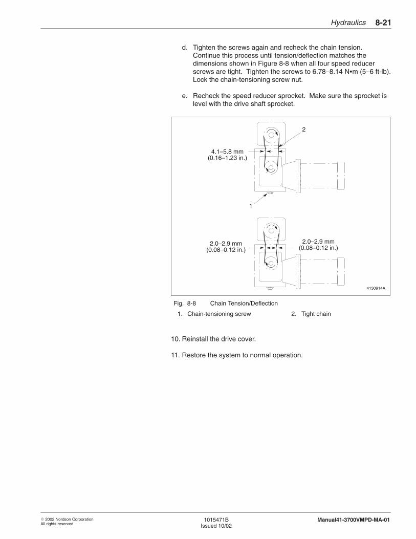
Hydraulics 8-21
� 2002 Nordson CorporationAll rights reserved
1015471BIssued 10/02
Manual41-3700VMPD-MA-01
d. Tighten the screws again and recheck the chain tension.Continue this process until tension/deflection matches thedimensions shown in Figure 8-8 when all four speed reducerscrews are tight. Tighten the screws to 6.78–8.14 N�m (5–6 ft-lb).Lock the chain-tensioning screw nut.
e. Recheck the speed reducer sprocket. Make sure the sprocket islevel with the drive shaft sprocket.
4130914A
1
2
4.1–5.8 mm(0.16–1.23 in.)
2.0–2.9 mm(0.08–0.12 in.)
2.0–2.9 mm(0.08–0.12 in.)
Fig. 8-8 Chain Tension/Deflection
1. Chain-tensioning screw 2. Tight chain
10. Reinstall the drive cover.
11. Restore the system to normal operation.

Hydraulics8-22
� 2002 Nordson CorporationAll rights reserved
1015471BIssued 10/02
Manual41-3700VMPD-MA-01

� 2002 Nordson CorporationAll rights reserved
1015471BIssued 10/02
Manual41-3700VMPD-MA-01
Section 9
Tank and Manifold

Tank and Manifold9-0
� 2002 Nordson CorporationAll rights reserved
1015471BIssued 10/02
Manual41-3700VMPD-MA-01
Tank and Manifold 9-1
� 2002 Nordson CorporationAll rights reserved
1015471BIssued 10/02
Manual41-3700VMPD-MA-01
Section 9Tank and Manifold
WARNING: Allow only qualified personnel to perform thefollowing tasks. Follow the safety instructions in this documentand all other related documentation.
This section describes how to disassemble and reassemble the tank andmanifold. It also includes procedures for replacing the pressure reliefvalve, drain valve, and an air-piloted pressure control valve.
Refer to the following sections for additional information on the tank andmanifold:
� Technical Data provides tank specifications, including the tankcapacity, the tank volume, and the dimensions of the tank lidopening.
� Operation includes the procedure for filling the tank with adhesive.
� Maintenance includes procedures for flushing the tank andmanifold and for draining adhesive from the tank.
� Control System includes procedures for replacing the tankresistance temperature detector (RTD) or thermostat.
� Parts includes illustrated parts lists for the melter and all majorassemblies. Refer to this section for the part number of anycomponent that needs to be replaced.
The tank holds a supply of adhesive and melts it before it is pumped tothe hoses and guns. An RTD and overtemperature thermostat sense thetank temperature and provide input to the control system. The tank isheated by a cast-in heating element.
1. Introduction
2. Overview of the Tank
Tank and Manifold9-2
� 2002 Nordson CorporationAll rights reserved
1015471BIssued 10/02
Manual41-3700VMPD-MA-01
Because the tank and manifold have no moving parts, you should notneed to replace them. However, if you need to remove them from themelter for any reason, follow these procedures. Refer to the Partssection for the part numbers of any components that need to be replaced.You can use the parts list illustrations as a guide as you perform thefollowing disassembly and reassembly procedures.
To replace both the tank and the manifold, you must complete all of thefollowing procedures:
� Preparing to Replace the Tank or Manifold� Disassembling the Tank and Manifold� Reassembling the Tank and Manifold� Restoring the Melter to Normal Operation
These instructions can also be used to replace just one part of the tankassembly.
Complete this procedure before you perform any tank repairs.
1. Heat the melter to operating temperature to aid disassembly and toprepare for draining as much adhesive as possible from the tank.
2. Drain the tank. For information about different ways to drain the tank,refer to Flushing the System in the Maintenance section.
3. Turn the pump air pressure regulator to 0; then disconnect the airregulator from the melter.
4. Remove the pump from the melter. Refer to the Hydraulics sectionfor the pump removal procedure.
5. Turn off the melter; disconnect and lock out electrical power to themelter at the branch circuit disconnect switch, and disconnect andlock out electrical power supplied through any I/O wiring.
3. Tank and ManifoldReplacement
Preparing to Replace the Tankor Manifold
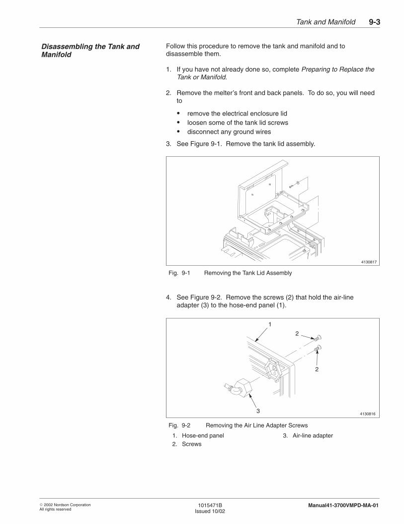
Tank and Manifold 9-3
� 2002 Nordson CorporationAll rights reserved
1015471BIssued 10/02
Manual41-3700VMPD-MA-01
Follow this procedure to remove the tank and manifold and todisassemble them.
1. If you have not already done so, complete Preparing to Replace theTank or Manifold.
2. Remove the melter’s front and back panels. To do so, you will needto
� remove the electrical enclosure lid� loosen some of the tank lid screws� disconnect any ground wires
3. See Figure 9-1. Remove the tank lid assembly.
4130817
Fig. 9-1 Removing the Tank Lid Assembly
4. See Figure 9-2. Remove the screws (2) that hold the air-line adapter (3) to the hose-end panel (1).
4130816
1
2
2
3
Fig. 9-2 Removing the Air Line Adapter Screws
1. Hose-end panel2. Screws
3. Air-line adapter
Disassembling the Tank andManifold
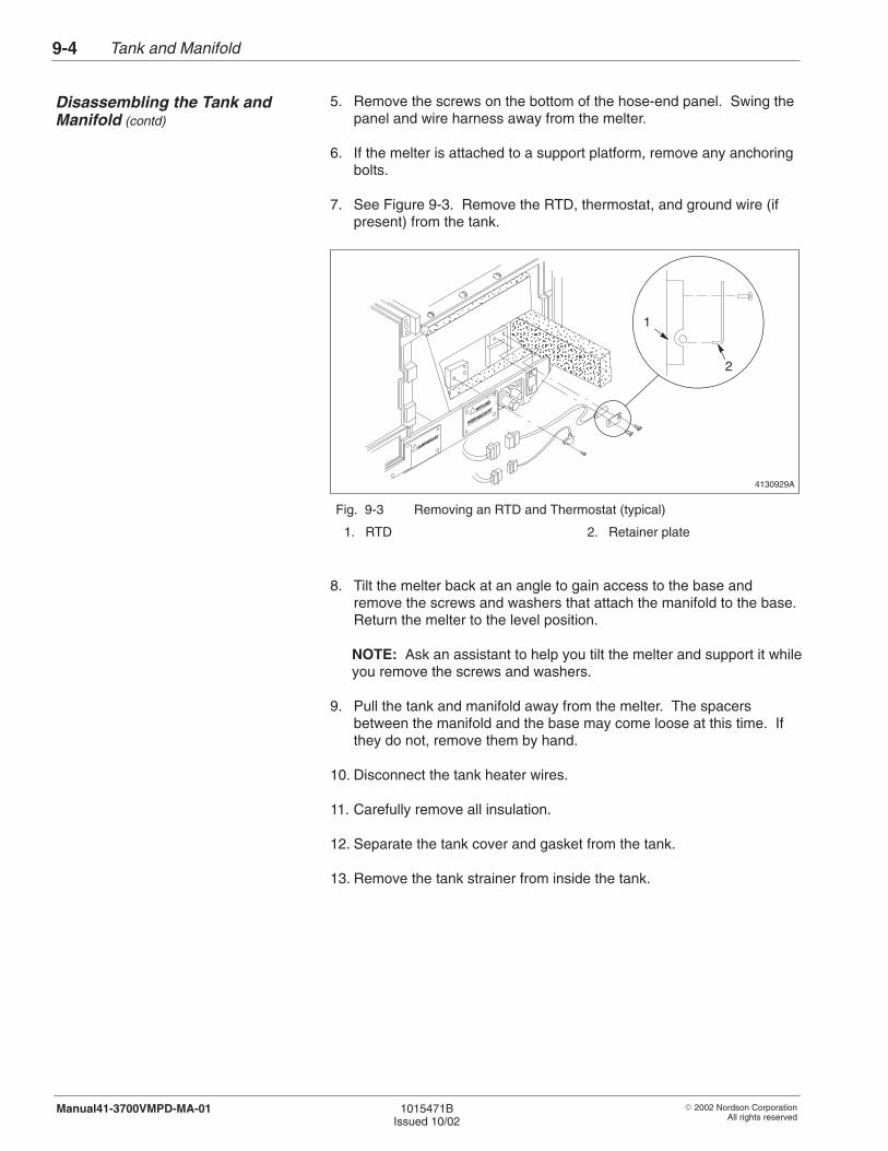
Tank and Manifold9-4
� 2002 Nordson CorporationAll rights reserved
1015471BIssued 10/02
Manual41-3700VMPD-MA-01
5. Remove the screws on the bottom of the hose-end panel. Swing thepanel and wire harness away from the melter.
6. If the melter is attached to a support platform, remove any anchoringbolts.
7. See Figure 9-3. Remove the RTD, thermostat, and ground wire (ifpresent) from the tank.
4130929A
ÎÎÎÎÎÎÎÎÎÎÎÎ
ÏÏÏÏÏÏÏÏÏÏÏÏÏÏÏÏÏÏÏÏ
ÎÎÎÎÎÎÎÎÎÎÎÎÎÎÎÎÎÎÎÎÎÎÎÎÎ
ÎÎÎÎ
ÎÎÎÎÎÎÎÎÎÎÎÎÎÎÎÎÎÎÎÎ
2
1
Fig. 9-3 Removing an RTD and Thermostat (typical)
1. RTD 2. Retainer plate
8. Tilt the melter back at an angle to gain access to the base andremove the screws and washers that attach the manifold to the base.Return the melter to the level position.
NOTE: Ask an assistant to help you tilt the melter and support it whileyou remove the screws and washers.
9. Pull the tank and manifold away from the melter. The spacersbetween the manifold and the base may come loose at this time. Ifthey do not, remove them by hand.
10. Disconnect the tank heater wires.
11. Carefully remove all insulation.
12. Separate the tank cover and gasket from the tank.
13. Remove the tank strainer from inside the tank.
Disassembling the Tank andManifold (contd)
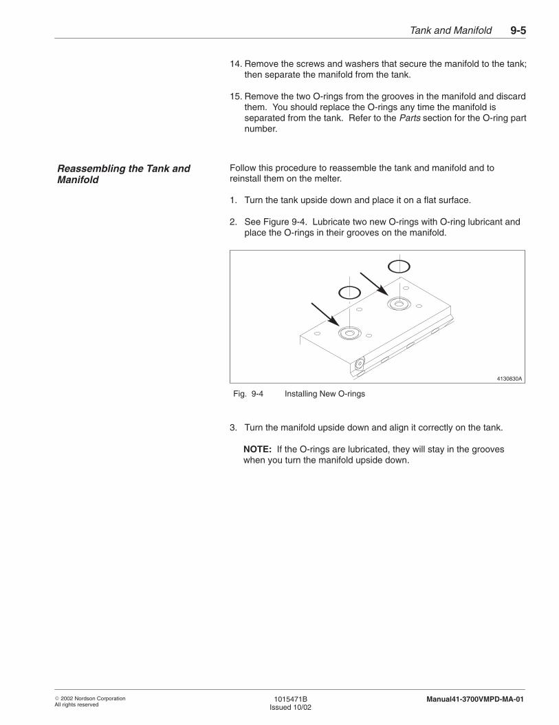
Tank and Manifold 9-5
� 2002 Nordson CorporationAll rights reserved
1015471BIssued 10/02
Manual41-3700VMPD-MA-01
14. Remove the screws and washers that secure the manifold to the tank;then separate the manifold from the tank.
15. Remove the two O-rings from the grooves in the manifold and discardthem. You should replace the O-rings any time the manifold isseparated from the tank. Refer to the Parts section for the O-ring partnumber.
Follow this procedure to reassemble the tank and manifold and toreinstall them on the melter.
1. Turn the tank upside down and place it on a flat surface.
2. See Figure 9-4. Lubricate two new O-rings with O-ring lubricant andplace the O-rings in their grooves on the manifold.
4130830A
Fig. 9-4 Installing New O-rings
3. Turn the manifold upside down and align it correctly on the tank.
NOTE: If the O-rings are lubricated, they will stay in the grooveswhen you turn the manifold upside down.
Reassembling the Tank andManifold
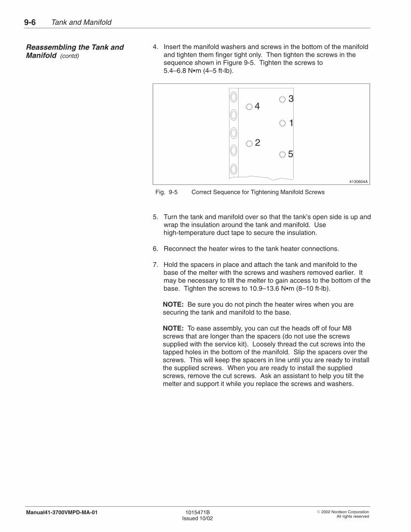
Tank and Manifold9-6
� 2002 Nordson CorporationAll rights reserved
1015471BIssued 10/02
Manual41-3700VMPD-MA-01
4. Insert the manifold washers and screws in the bottom of the manifoldand tighten them finger tight only. Then tighten the screws in thesequence shown in Figure 9-5. Tighten the screws to5.4–6.8 N�m (4–5 ft-lb).
4130604A
1
2
34
5
Fig. 9-5 Correct Sequence for Tightening Manifold Screws
5. Turn the tank and manifold over so that the tank’s open side is up andwrap the insulation around the tank and manifold. Usehigh-temperature duct tape to secure the insulation.
6. Reconnect the heater wires to the tank heater connections.
7. Hold the spacers in place and attach the tank and manifold to thebase of the melter with the screws and washers removed earlier. Itmay be necessary to tilt the melter to gain access to the bottom of thebase. Tighten the screws to 10.9–13.6 N�m (8–10 ft-lb).
NOTE: Be sure you do not pinch the heater wires when you aresecuring the tank and manifold to the base.
NOTE: To ease assembly, you can cut the heads off of four M8screws that are longer than the spacers (do not use the screwssupplied with the service kit). Loosely thread the cut screws into thetapped holes in the bottom of the manifold. Slip the spacers over thescrews. This will keep the spacers in line until you are ready to installthe supplied screws. When you are ready to install the suppliedscrews, remove the cut screws. Ask an assistant to help you tilt themelter and support it while you replace the screws and washers.
Reassembling the Tank andManifold (contd)
Tank and Manifold 9-7
� 2002 Nordson CorporationAll rights reserved
1015471BIssued 10/02
Manual41-3700VMPD-MA-01
8. Apply thermal compound to the RTD and thermostat and install themon the side of the tank. Make sure the RTD retainer plate is installedas shown in Figure 9-3.
9. Reconnect the ground wire (if present) to the tank.
10. If the melter was attached to a support platform, anchor it to theplatform now.
11. Lay the tank strainer in the bottom of the tank.
12. Install a new tank gasket and secure the tank cover to the tank.
NOTE: You should replace the tank gasket any time the tank cover isseparated from the tank.
13. Swing the wire harness and hose-end panel into position and securethe hose-end panel with the screws you removed earlier.
14. Make sure the air-line adapter is securely inserted in the recessedarea on the inside of the hose-end panel. Secure the adapter withthe screws you removed earlier.
15. Install the pump air pressure regulator and connect the incoming airline to the regulator.
16. Install the tank lid assembly using the screws you removed earlier.
17. Install the melter’s front and back panels.
Follow this procedure to reinstall the pump and restore the melter tonormal operation.
1. Install the pump. Refer to the Hydraulics section for pump installationprocedures.
2. Install and secure the pump cover and, if applicable, the drive cover.
3. Return the pump air pressure to the normal operating setting.
4. Remove the lock-out and restore power to the melter.
Restoring the Melter to NormalOperation
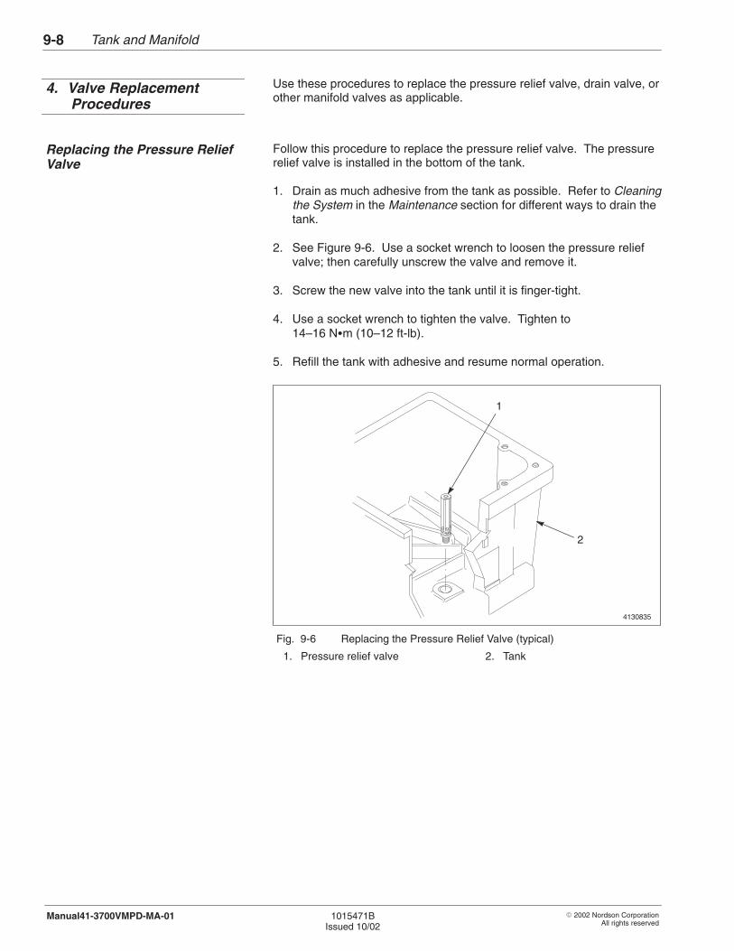
Tank and Manifold9-8
� 2002 Nordson CorporationAll rights reserved
1015471BIssued 10/02
Manual41-3700VMPD-MA-01
Use these procedures to replace the pressure relief valve, drain valve, orother manifold valves as applicable.
Follow this procedure to replace the pressure relief valve. The pressurerelief valve is installed in the bottom of the tank.
1. Drain as much adhesive from the tank as possible. Refer to Cleaningthe System in the Maintenance section for different ways to drain thetank.
2. See Figure 9-6. Use a socket wrench to loosen the pressure reliefvalve; then carefully unscrew the valve and remove it.
3. Screw the new valve into the tank until it is finger-tight.
4. Use a socket wrench to tighten the valve. Tighten to14–16 N�m (10–12 ft-lb).
5. Refill the tank with adhesive and resume normal operation.
4130835
1
2
Fig. 9-6 Replacing the Pressure Relief Valve (typical)
1. Pressure relief valve 2. Tank
4. Valve ReplacementProcedures
Replacing the Pressure ReliefValve
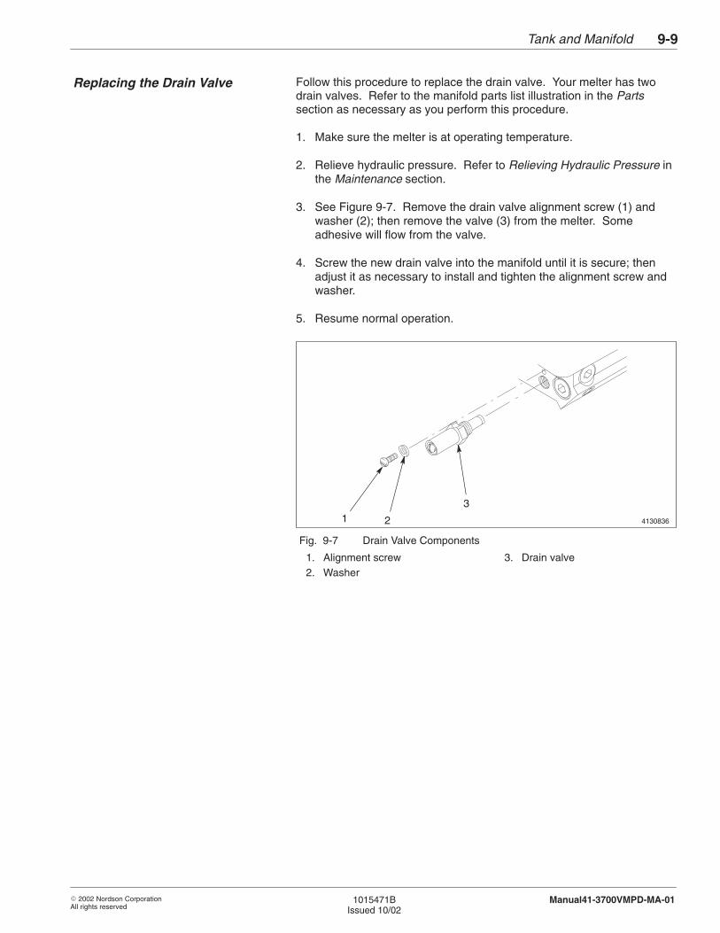
Tank and Manifold 9-9
� 2002 Nordson CorporationAll rights reserved
1015471BIssued 10/02
Manual41-3700VMPD-MA-01
Follow this procedure to replace the drain valve. Your melter has twodrain valves. Refer to the manifold parts list illustration in the Partssection as necessary as you perform this procedure.
1. Make sure the melter is at operating temperature.
2. Relieve hydraulic pressure. Refer to Relieving Hydraulic Pressure inthe Maintenance section.
3. See Figure 9-7. Remove the drain valve alignment screw (1) andwasher (2); then remove the valve (3) from the melter. Someadhesive will flow from the valve.
4. Screw the new drain valve into the manifold until it is secure; thenadjust it as necessary to install and tighten the alignment screw andwasher.
5. Resume normal operation.
41308361 2
3
Fig. 9-7 Drain Valve Components
1. Alignment screw2. Washer
3. Drain valve
Replacing the Drain Valve
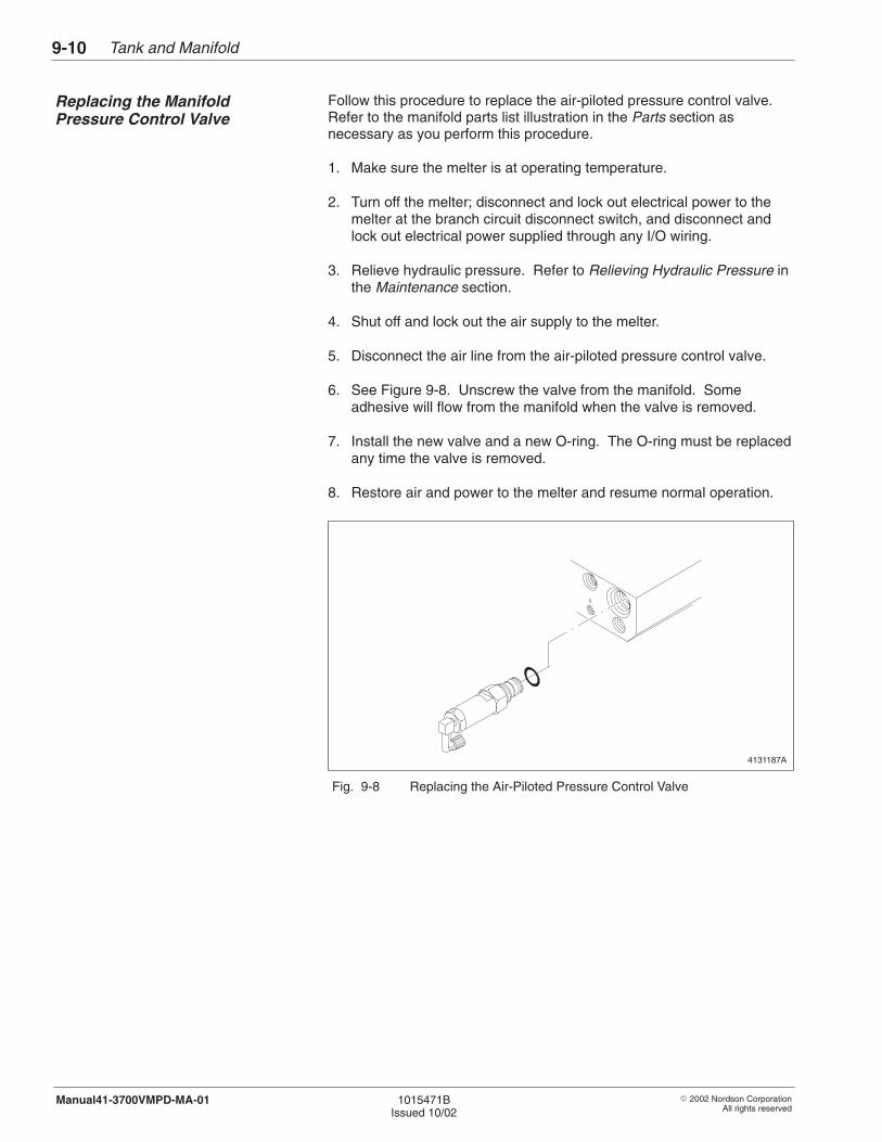
Tank and Manifold9-10
� 2002 Nordson CorporationAll rights reserved
1015471BIssued 10/02
Manual41-3700VMPD-MA-01
Follow this procedure to replace the air-piloted pressure control valve.Refer to the manifold parts list illustration in the Parts section asnecessary as you perform this procedure.
1. Make sure the melter is at operating temperature.
2. Turn off the melter; disconnect and lock out electrical power to themelter at the branch circuit disconnect switch, and disconnect andlock out electrical power supplied through any I/O wiring.
3. Relieve hydraulic pressure. Refer to Relieving Hydraulic Pressure inthe Maintenance section.
4. Shut off and lock out the air supply to the melter.
5. Disconnect the air line from the air-piloted pressure control valve.
6. See Figure 9-8. Unscrew the valve from the manifold. Someadhesive will flow from the manifold when the valve is removed.
7. Install the new valve and a new O-ring. The O-ring must be replacedany time the valve is removed.
8. Restore air and power to the melter and resume normal operation.
4131187A
Fig. 9-8 Replacing the Air-Piloted Pressure Control Valve
Replacing the ManifoldPressure Control Valve

� 2002 Nordson CorporationAll rights reserved
1015471BIssued 10/02
Manual41-3700VMPD-MA-01
Section 10
Schematics

Schematics10-0
� 2002 Nordson CorporationAll rights reserved
1015471BIssued 10/02
Manual41-3700VMPD-MA-01
(This page intentionally left blank.)
Schematics 10-1
� 2002 Nordson CorporationAll rights reserved
1015471BIssued 10/02
Manual41-3700VMPD-MA-01
Section 10Schematics
The wiring diagrams contained in this section are based on the voltagecode of your unit. Refer to the following table to determine the voltagecode of your unit; then refer to the appropriate wiring diagram in thissection.
Each wiring diagram shows all of the options or special features the unitcan be equipped with. Options and special features are indicated bydotted lines. To determine the features and options of your unit, refer toExplanation of Configuration Code at the end of the Description section.
1. Introduction
2. Use of Wiring Diagrams

Schematics10-2
� 2002 Nordson CorporationAll rights reserved
1015471BIssued 10/02
Manual41-3700VMPD-MA-01
This page intentionally left blank

Schematics 10-3
� 2002 Nordson CorporationAll rights reserved
1015471BIssued 10/02
Manual41-3700VMPD-MA-01
F10
BLU
E
MJ
HE
AT
ER
TH
ER
MO
STA
TO
VE
RT
EM
PTA
NK
12
TAN
K/R
ES
RT
D12
HE
AT
ER
TAN
K/R
ES
RT
D
HC
4
GU
N4
HC
3
GU
N3
GU
N2
X2
PO
WE
R B
OA
RD
33
TS
TAT
43
21
12
12
NO
T R
EA
DY
FAU
LT
WA
RN
ING
J2 6 5 14 3 2 TB
2
87
65
32
14
21
J9X
1
L2N L3 L1T
B1
J41
K1
24
5
F2
F1
F3
F4
PO
WE
R O
N/O
FF
CO
NT
RO
L BO
AR
D
DIG
ITAL P
RO
CE
SS
OR
21X
S1
XS
27
86
45
23
120
1817
1916
1513
1214
1110
87
96
53
24
1
XP
2
PO
WE
R
F11
F7
F6
F5
F8
F12
XP
1
3635
3332
3431
3028
2729
2625
2322
24
HC
2
HC
1
GU
N1
BA
BC
J1CJ2C
X2C
L3 L2N L1
F3
F2 F1
X1C
XS
4A,B
,C
XS
2A,B
XS
3A,B
,C,D
CO
NTA
CT
OR
BO
AR
D
K1
XS
1A
T.S.
HE
AT
ER
GR
ID B
D
XS
1GR CE
XS
2GR
RT
D
BD
X3H
BF
F2
F4 F3
XS
2H 5/6 HO
SE
/GU
N B
OA
RD
F1
XS
1H
2234
X2H 431
HC
6
X1H1
HC
5
GU
N6
GU
N5
BA
BF
CE
BD
BC
CG
I/O B
OA
RD
DIS
PLA
Y
PL1
XP
4AX
P5
CC
CG
CC
FO
R R
EF
ER
EN
CE
ON
LY
200–240V 1
CH
(+)C
I (–)
230V 1
X1C400V
/230V 3
X2C
X3
X4
1
15
HG
1
HG
2
HG
3
HG
4G3
CONTROL FRAME G1REAR PANEL G2FRONT PANEL G4TOP COVER G5EXPANSION BASE PLATE G6
12
34
5
HG
5
HG
6
G7
GR
ID2
1
X1G
R
1
1215
1
12
21
15 X1C
12 X2C
11
12
200–240V 1
15
1X
1C1
X2C
FO
R R
EF
ER
EN
CE
ON
LY
12
200–240V 3
15
1X
1C1
X2C
1215
11
X1C
& X
2C C
ON
NE
CT
ION
S
15
1X
3
X3 &
X4 C
ON
NE
CT
ION
S
X4
15
400V/230V
3
1X
3
X4
15
230 1
1X
3
15
200–240V 3
1X
3
21
21
1 12 2
562178431
23
45
GN
D
TB
1AT
B1B
TB
1CT
B1D
21
45
12
3
12
34
56
78
12
65
43
21
2625
2423
2220
1918
1721
1514
1312
109
87
1116
3534
3332
3029
2827
3136
61
23
45
2616
117
89
1012131415
2117181920
2223242536
3127282930
32333435
XP
7X
P8
BX
P7
XP
2B
XP
2A
3
1
3
1
33
3
J1
3BG
4F
RO
NT
HG
3
HG
4
G6
G5
3C 2C 5D 2B
H/G
3
H/G
4
EX
P.B
AS
EP
LAT
E
CO
VE
RT
OP
PA
NE
L
G3
HG
2
HG
1
G2
G1
WIR
E
3D3A
2D
LOC
AT
ION
2A
1A
TAN
K/R
ES
H/G
2
H/G
1
PA
NE
LR
EA
R
FR
AM
EC
ON
TR
OL
SO
UR
CE G
RO
UN
D S
TAC
K LIS
T
H/G
6
H/G
5
HG
6
HG
5
4D 4C
MO
TOR
GR
ID
G9
G7
4C 5B
MO
TOR
G8
4AC
ON
TR
OL
BR
AC
KE
T
G9
XP
3
LEV
EL 4
LEV
EL 3
LEV
EL 2
LEV
EL 1
LEV
EL 5
B D
AC
XP
9X
P10
BX
P7
XP
1
KE
YP
AD
CO
VE
R
HO
PP
ER
G10
4B
HOPPER COVER G10
JUM
PE
R W
HE
NG
RID
IS N
OT
PR
ES
EN
T
F13
F14
XS
3X
S4
BL
BM
3
F9
JUM
PE
R IS
PR
ES
EN
T IN
J2N
OT
E: F
OR
MO
TO
R O
PT
ION
J2
4HE
AT
ER
2G 1
RT
D534
HE
AT
ER
2G 1
RT
D534
HE
AT
ER
2G 1
RT
D534
HE
AT
ER
2G 1
RT
D53
4HE
AT
ER
2G 1
RT
D534H
EA
TE
R2G 1
RT
D53
RT
D
HE
AT
ER32G 1 4 5
631027 121 59 8 11 4
RT
D
HE
AT
ER32G 1 4 5
631027 121 59 8 11 4
RT
D
HE
AT
ER32G 1 4 5
631027 121 59 8 11 4
RT
D
HE
AT
ER32G 1 4 5
631027 121 59 8 11 4
10:1 PU
MP
PU
MP
5B
HOSES AND GUNS ARE EXTERNAL TO THE SYSTEM
EX
TE
RN
AL C
ON
NE
CT
ION
S
CU
ST
OM
ER
I/O
INC
OM
ING
PO
WE
R200V
–240V400V
/230V
EX
TE
RN
AL C
ON
NE
CT
ION
SC
US
TO
ME
R I/O
CO
NN
EC
TIO
NS
EX
TE
RN
AL
I/OC
US
TO
ME
R
RT
D
HE
AT
ER32G 1 4 5
631027 121 59 8 11 4
RT
D32G 1 4 5
631027 121 59 8 11 4
HOSES AND GUNS ARE EXTERNAL TO THE SYSTEM
232719
232707
232709232708
TANK G7
HOSE/GUN 5 HC5
HOSE/GUN 6 HC6
227567227568
232617227569
A–
A+
L2
L1
F–
F+
I1
COM
SIG
+12
Si–5 IS
OLA
TIO
N B
OA
RD
KB
IC D
CD
RIV
EB
OA
RD
I/PT
RA
NS
DU
CE
R
MO
TOR
O.O
.R.
OV
ER
TE
MP
ER
AT
UR
ET
HE
RM
OS
TAT
DC
MO
TO
R
TO
V–to–I
BO
AR
D, X
2
MT
JUM
PE
R F
OR
INH
IBIT
FU
NC
TIO
N BLA
CK
(+)
WH
ITE
(–)2 1
MJ
X1–7 or TB10–3X1–8 or TB10–4
RE
DB
LAC
K
TB
3
I1
MT
RS
–232B
OA
RD
XS
C1
XP
5
EIT
HE
R T
HE
RS
–232 BO
AR
D, T
HE
PC
EN
GIN
E B
OA
RD
, OR
NE
ITH
ER
IS IN
PLA
CE
; NE
VE
R B
OT
H
A1
A2
TH
TH
12
J10
12
321 2 134 43 2156 12
54 61 2 3 10987 1 2 3 4
X4
X5XT
7
X6
X2
X1
XT
3
109
87
63
24
15
1112
BLA
CK
BR
OW
NLO
W–LE
VE
LS
EN
SO
R
JJ
JJ
CI
CH
AU
TO
/MA
NU
AL S
WIT
CH
& LE
D
RE
AR
VIE
W
CC
WC
WP
RS
MO
T
NO
TE
: MO
TO
R O
PT
ION
IS IN
PLA
CE
WH
EN
PIS
TO
N P
UM
P IS
NO
T U
SE
D
J15V
240V240V
+–
V–to–I
BO
AR
D
X1 &
X2 or T
B10 &
TB
20
BO
AR
D
CO
NT
RO
L
SU
PP
LY
1014454
XP
6
+–
Fig. 10-1 Wiring Diagram
Schematics10-4
� 2002 Nordson CorporationAll rights reserved
1015471BIssued 10/02
Manual41-3700VMPD-MA-01
(This page intentionally left blank.)

Schematics 10-5
� 2002 Nordson CorporationAll rights reserved
1015471BIssued 10/02
Manual41-3700VMPD-MA-01
POWER BOARD
L2L1
L3
N
54
12
4321
56
WARNINGFAULT
NOT READY
POWER SUPPLY+5VDC
+12VDC–12VDC+24VDC
CONTROL BOARD
DISPLAY BOARD
KEYPAD
PO
WE
R
K1
X3
X4
DIGITAL
XP1
XP3
XP4A
PL1
XP5
XP6
J2
J9
X2
X1
XS1
XS2
IndicatorPower
TB1
SW
ITC
HE
S
F11
F12
F1F2F3F4
F5F6F7F8
PROCESSOR
XP2
XP1
J4
TB2
POWER ON/OFF
READY
FAULT/WARNING
F9
F10
TANK HEATER
TANKOVERTEMPERATURE
THERMOSTAT
HOSECONNECTORS
pattern controller. option)
HC1
HC2
HC3
HC4
5/6
BOARDHOSE/GUN
CONTROLGRID
(for serial comm or
1.) PARTS IN DOTTED LINE ARE OPTIONAL.
NOTES:
X1GRXS2GR
GRIDRTD
HEATERGRID
XS2H
XS1H
X2H
X1H HC5
HC6
TANKRTD
CONTACTORBOARD
L1
L2
L3
N
XS4
J2C
GRID
THERMOSTATOVERTEMPERATURE
200–240V 3AND 400V/230V 3 CONFIGURATION
XS3XS2XS1
XS1GR
GRID RTDCONNECTION
X3H
I/O BOARD
CONNECTIONTSTAT
CONNECTIONTANK RTD
J1C
1234
GRID TSTATCONNECTION
BE USED WHENJUMPER WILL NOT
GRID THERMOSTATIS IN PLACE
LOAD CONFIGURATION FOR 200V–240V 3
TANK
(PE)GND
N
L2L3
L1TB1
PATTERNCONTROLLER5&6
H/G
GRID1–4H/G
L3
TANKGND(PE)
N
CONTROLLER1–4H/G
5&6GRID
LOAD CONFIGURATION FOR 400V/230V 3
L1L2
TB1
PATTERNH/G
MOTOR
TB1A
TB1B
TB1C
TB1D
XS3 XS4
OVERTEMPERATURETHERMOSTAT
XS3M
HOSE
SYSTEM CONNECTIONTYPICAL HOSE & GUN
GUN
HOSE
SYSTEM CONNECTION
TYPICAL HOSE & GUN
GUN
CUSTOMER I/O
X1 & X2 or TB10 & TB20
200V–240VACPOWER
INCOMING
CUSTOMER I/O
400/230 VAC
2.) PARTS IN DASH DOT DOT DASH ARE EXTERNAL CONNECTIONS.
KBIC MOTOR DRIVE
SI–5 ISOLATION MODULE
DC MOTORF14
F13
DCMOTOR
DCMOTOR
I/P
INHIBIT JUMPER
RS–232BOARD
XP5 XSC1
EITHER THE RS–232 BOARD, ORTHE PC ENGINE BOARD, ORNEITHER IS IN PLACE; NEVERBOTH
JUMPER J2FOR MOTOROPERATION
J10
5VJ1
240V 240V
COMSIG+12
I1
L1F–F+
A–A+L2
MANUAL/AUTO SELECT SWITCH & LED
SET MOTOR &PRESSURE
LOW–LEVEL (COM)LOW–LEVEL (N.C.)LOW–LEVEL (N.O.)
PRESSURE 4–20 mA (–)PRESSURE 4–20 mA (+)
MOTOR 4–20 mA (+)
MANUAL MODE OUTPUTMANUAL MODE OUTPUT
MOTOR 4–20 mA (–)
REM. MTR. START INPUTREM. MTR. START INPUT
123456789
101112
V–TO–I BOARD
XT3X4 X5 XT7 X6
X1X2
LOW–LEVELSENSOR
1014453
TRANSDUCER
MANUALLY
∅
∅
∅
∅
Fig. 10-2 Schematic

Schematics10-6
� 2002 Nordson CorporationAll rights reserved
1015471BIssued 10/02
Manual41-3700VMPD-MA-01
(This page intentionally left blank.)
� 2002 Nordson CorporationAll rights reserved
1015471BIssued 10/02
Manual41-3700VMPD-MA-01
Section 11
Parts

Parts11-0
� 2002 Nordson CorporationAll rights reserved
1015471BIssued 10/02
Manual41-3700VMPD-MA-01

Parts 11-1
� 2002 Nordson CorporationAll rights reserved
1015471BIssued 10/02
Manual41-3700VMPD-MA-01
Section 11Parts
To order parts, call the Nordson Customer Service Center or your localNordson representative. Use the parts list, and the accompanyingillustration, to describe and locate parts correctly.
Numbers in the Item column correspond to numbers that identify parts inillustrations following each parts list. The code NS (not shown) indicatesthat a listed part is not illustrated. A dash (—) is used when the partnumber applies to all parts in the illustration.
The number in the Part column is the Nordson Corporation part number.A series of dashes in this column (- - - - - -) means the part cannot beordered separately.
The Description column gives the part name, as well as its dimensionsand other characteristics when appropriate. Indentions show therelationships between assemblies, subassemblies, and parts.
Item Part Description Quantity Note
— 000 0000 Assembly 1
1 000 000 � Subassembly 2 A
2 000 000 � � Part 1
� If you order the assembly, items 1 and 2 will be included.� If you order item 1, item 2 will be included.� If you order item 2, you will receive item 2 only.
The number in the Quantity column is the quantity required per melter,assembly, or subassembly. The code AR (As Required) is used if thepart number is a bulk item ordered in quantities or if the quantity perassembly depends on the product version or model.
Letters in the Note column refer to notes at the end of each parts list.Notes contain important information about usage and ordering. Specialattention should be given to notes.
1. Introduction
Using the Illustrated PartsList
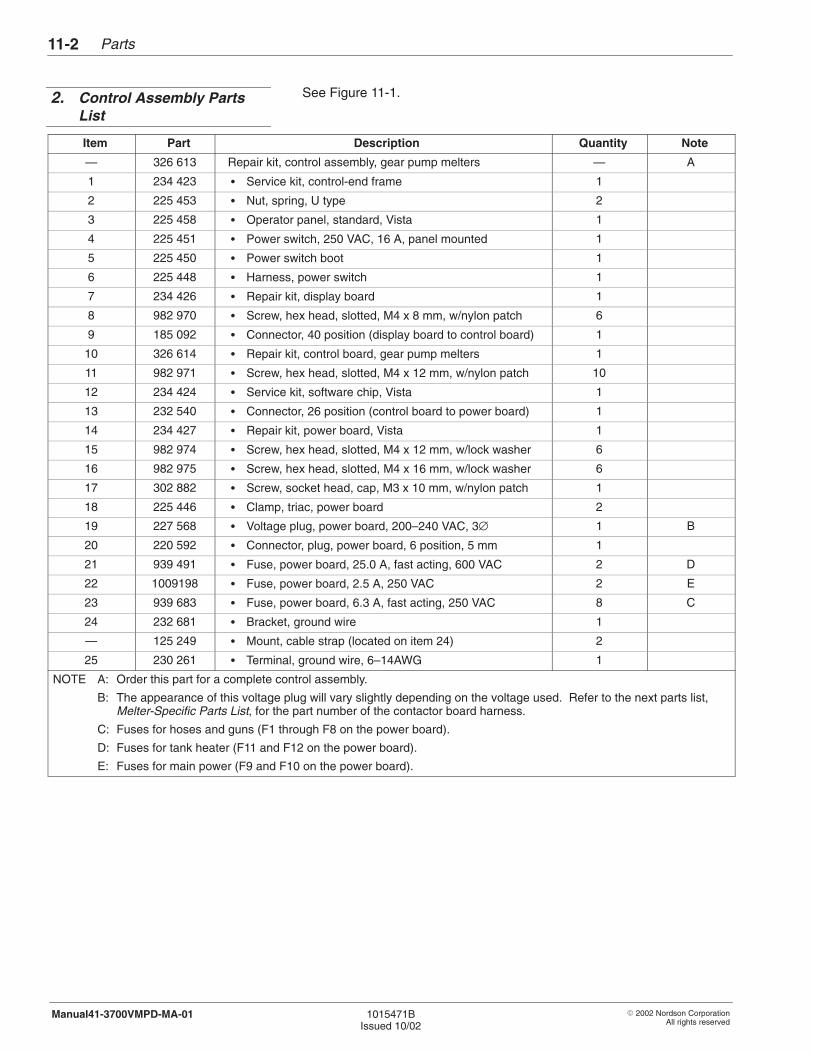
Parts11-2
� 2002 Nordson CorporationAll rights reserved
1015471BIssued 10/02
Manual41-3700VMPD-MA-01
See Figure 11-1.
Item Part Description Quantity Note
— 326 613 Repair kit, control assembly, gear pump melters — A
1 234 423 � Service kit, control-end frame 1
2 225 453 � Nut, spring, U type 2
3 225 458 � Operator panel, standard, Vista 1
4 225 451 � Power switch, 250 VAC, 16 A, panel mounted 1
5 225 450 � Power switch boot 1
6 225 448 � Harness, power switch 1
7 234 426 � Repair kit, display board 1
8 982 970 � Screw, hex head, slotted, M4 x 8 mm, w/nylon patch 6
9 185 092 � Connector, 40 position (display board to control board) 1
10 326 614 � Repair kit, control board, gear pump melters 1
11 982 971 � Screw, hex head, slotted, M4 x 12 mm, w/nylon patch 10
12 234 424 � Service kit, software chip, Vista 1
13 232 540 � Connector, 26 position (control board to power board) 1
14 234 427 � Repair kit, power board, Vista 1
15 982 974 � Screw, hex head, slotted, M4 x 12 mm, w/lock washer 6
16 982 975 � Screw, hex head, slotted, M4 x 16 mm, w/lock washer 6
17 302 882 � Screw, socket head, cap, M3 x 10 mm, w/nylon patch 1
18 225 446 � Clamp, triac, power board 2
19 227 568 � Voltage plug, power board, 200–240 VAC, 3∅ 1 B
20 220 592 � Connector, plug, power board, 6 position, 5 mm 1
21 939 491 � Fuse, power board, 25.0 A, fast acting, 600 VAC 2 D
22 1009198 � Fuse, power board, 2.5 A, 250 VAC 2 E
23 939 683 � Fuse, power board, 6.3 A, fast acting, 250 VAC 8 C
24 232 681 � Bracket, ground wire 1
— 125 249 � Mount, cable strap (located on item 24) 2
25 230 261 � Terminal, ground wire, 6–14AWG 1
NOTE A: Order this part for a complete control assembly.
B: The appearance of this voltage plug will vary slightly depending on the voltage used. Refer to the next parts list,Melter-Specific Parts List, for the part number of the contactor board harness.
C: Fuses for hoses and guns (F1 through F8 on the power board).
D: Fuses for tank heater (F11 and F12 on the power board).
E: Fuses for main power (F9 and F10 on the power board).
2. Control Assembly PartsList
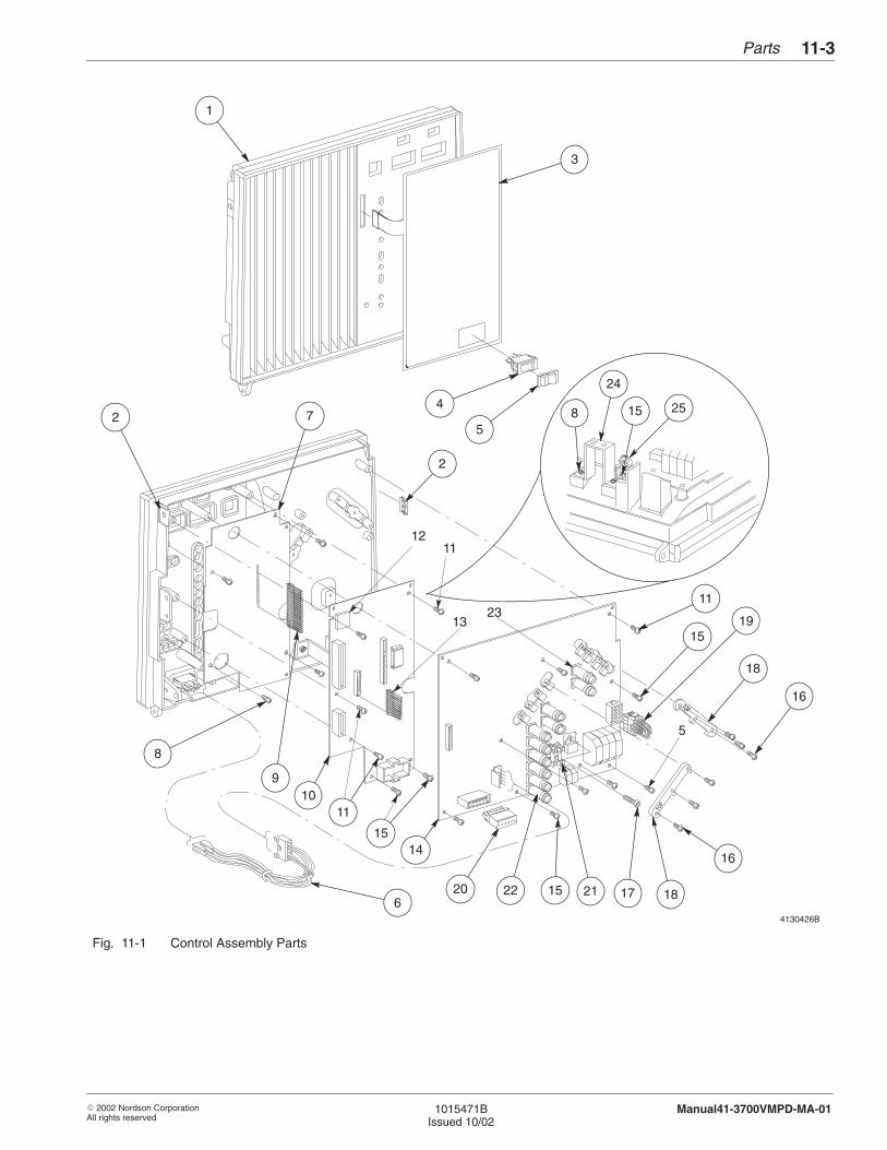
Parts 11-3
� 2002 Nordson CorporationAll rights reserved
1015471BIssued 10/02
Manual41-3700VMPD-MA-01
13
12
5
23
11
1
3
4
52 7 8 15
24
25
8
9
2
19
11
16
18
15
16
1011
1415
2220 15 21 186
17
4130426B
Fig. 11-1 Control Assembly Parts

Parts11-4
� 2002 Nordson CorporationAll rights reserved
1015471BIssued 10/02
Manual41-3700VMPD-MA-01
See Figure 11-2.
Item Part Description Quantity Note
1 247 266 Repair kit, contactor board 1
2 - - - - - - Fuse, contactor board, 25 A or 30 A, fast acting, 600 VAC 2 A
3 232 707 Harness, contactor board, 200–240 VAC, 3∅ 1
NS 302 204 Harness, contactor board, power input 1
4 1017 797 Kit, Motor drive board w/isolation, V/MPD 1
5 1017 796 Kit, V-I board, V/MPD 1
6 1017 811 Kit, MPD panel w/o Com port 1
7 247 261 Repair kit, I/O board, standard 1
239 494 Repair kit, I/O board, enhanced 1
NOTE A: This board can have one, two, or three fuses. Fuse positions F1 and F2 are shown in the illustration. Fuse positionF3 is not. If the fuse you are replacing is a 25 A fuse, order part 939 491. If the fuse you are replacing is a 30 Afuse, order part 939 992. Check the fuse label for the fuse amperage.
NS: Not Shown
Melter-Specific Parts List
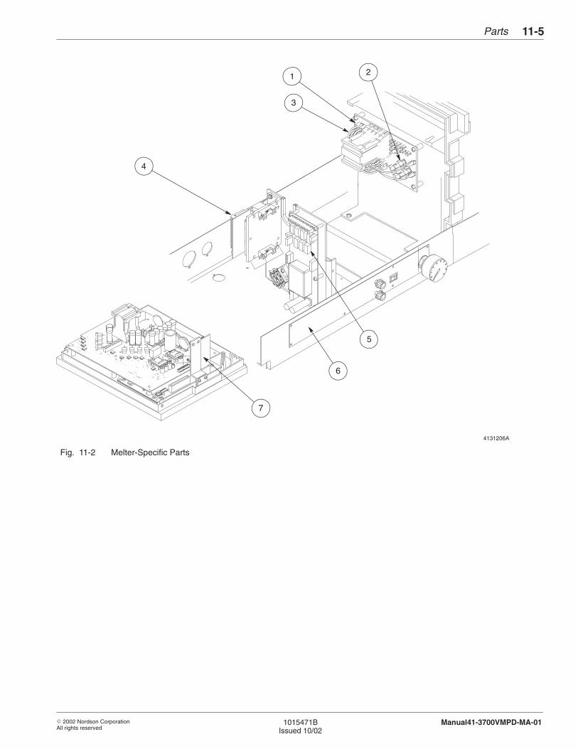
Parts 11-5
� 2002 Nordson CorporationAll rights reserved
1015471BIssued 10/02
Manual41-3700VMPD-MA-01
4131206A
+
7
3
1 2
4
5
6
Fig. 11-2 Melter-Specific Parts
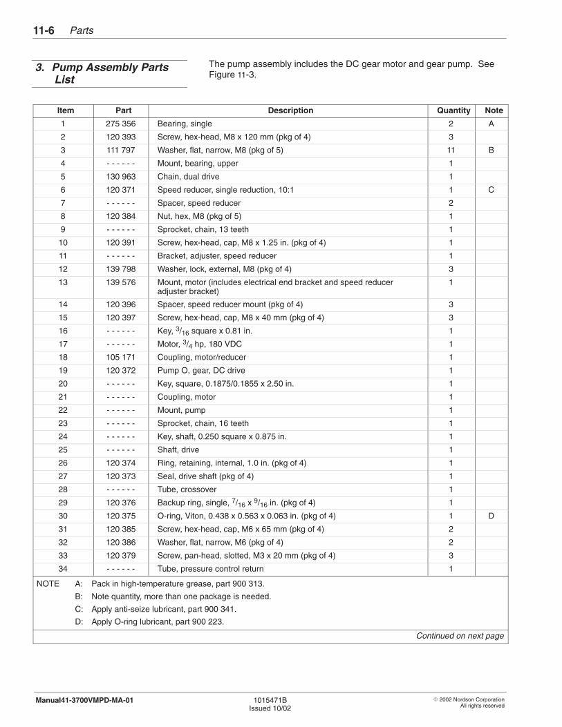
Parts11-6
� 2002 Nordson CorporationAll rights reserved
1015471BIssued 10/02
Manual41-3700VMPD-MA-01
The pump assembly includes the DC gear motor and gear pump. SeeFigure 11-3.
Item Part Description Quantity Note
1 275 356 Bearing, single 2 A
2 120 393 Screw, hex-head, M8 x 120 mm (pkg of 4) 3
3 111 797 Washer, flat, narrow, M8 (pkg of 5) 11 B
4 - - - - - - Mount, bearing, upper 1
5 130 963 Chain, dual drive 1
6 120 371 Speed reducer, single reduction, 10:1 1 C
7 - - - - - - Spacer, speed reducer 2
8 120 384 Nut, hex, M8 (pkg of 5) 1
9 - - - - - - Sprocket, chain, 13 teeth 1
10 120 391 Screw, hex-head, cap, M8 x 1.25 in. (pkg of 4) 1
11 - - - - - - Bracket, adjuster, speed reducer 1
12 139 798 Washer, lock, external, M8 (pkg of 4) 3
13 139 576 Mount, motor (includes electrical end bracket and speed reduceradjuster bracket)
1
14 120 396 Spacer, speed reducer mount (pkg of 4) 3
15 120 397 Screw, hex-head, cap, M8 x 40 mm (pkg of 4) 3
16 - - - - - - Key, 3/16 square x 0.81 in. 1
17 - - - - - - Motor, 3/4 hp, 180 VDC 1
18 105 171 Coupling, motor/reducer 1
19 120 372 Pump O, gear, DC drive 1
20 - - - - - - Key, square, 0.1875/0.1855 x 2.50 in. 1
21 - - - - - - Coupling, motor 1
22 - - - - - - Mount, pump 1
23 - - - - - - Sprocket, chain, 16 teeth 1
24 - - - - - - Key, shaft, 0.250 square x 0.875 in. 1
25 - - - - - - Shaft, drive 1
26 120 374 Ring, retaining, internal, 1.0 in. (pkg of 4) 1
27 120 373 Seal, drive shaft (pkg of 4) 1
28 - - - - - - Tube, crossover 1
29 120 376 Backup ring, single, 7/16 x 9/16 in. (pkg of 4) 1
30 120 375 O-ring, Viton, 0.438 x 0.563 x 0.063 in. (pkg of 4) 1 D
31 120 385 Screw, hex-head, cap, M6 x 65 mm (pkg of 4) 2
32 120 386 Washer, flat, narrow, M6 (pkg of 4) 2
33 120 379 Screw, pan-head, slotted, M3 x 20 mm (pkg of 4) 3
34 - - - - - - Tube, pressure control return 1
NOTE A: Pack in high-temperature grease, part 900 313.
B: Note quantity, more than one package is needed.
C: Apply anti-seize lubricant, part 900 341.
D: Apply O-ring lubricant, part 900 223.
Continued on next page
3. Pump Assembly PartsList
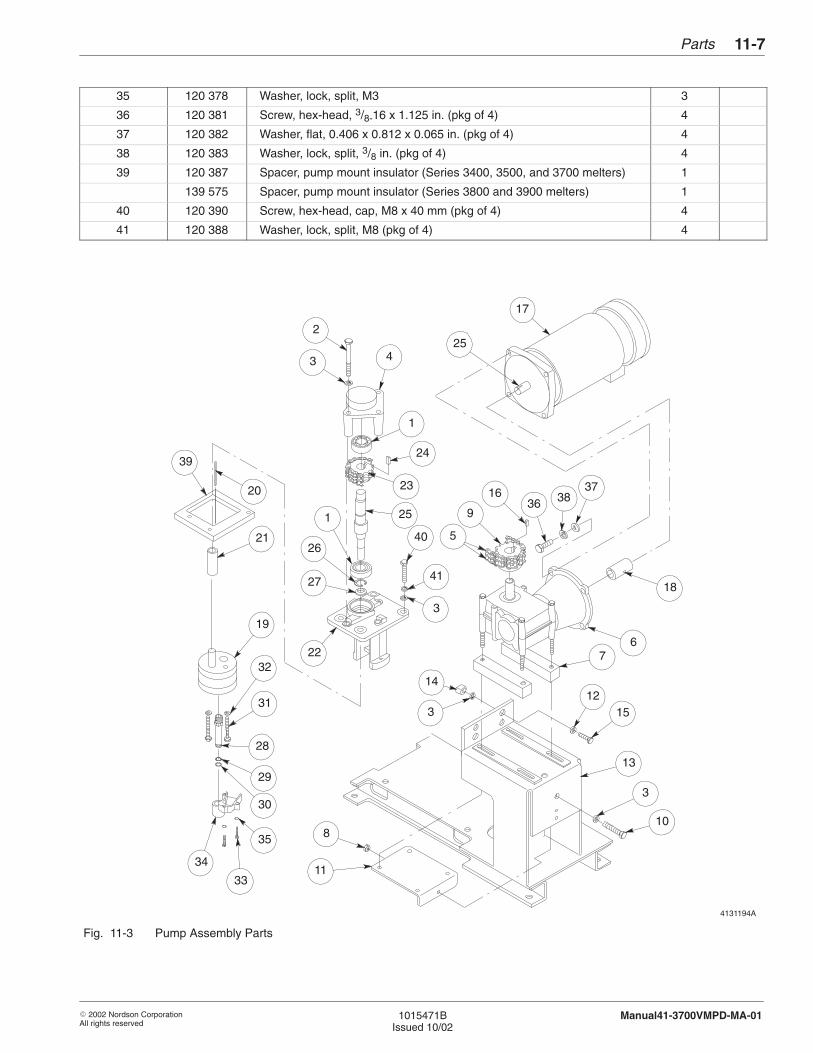
Parts 11-7
� 2002 Nordson CorporationAll rights reserved
1015471BIssued 10/02
Manual41-3700VMPD-MA-01
35 120 378 Washer, lock, split, M3 3
36 120 381 Screw, hex-head, 3/8-16 x 1.125 in. (pkg of 4) 4
37 120 382 Washer, flat, 0.406 x 0.812 x 0.065 in. (pkg of 4) 4
38 120 383 Washer, lock, split, 3/8 in. (pkg of 4) 4
39 120 387 Spacer, pump mount insulator (Series 3400, 3500, and 3700 melters) 1
139 575 Spacer, pump mount insulator (Series 3800 and 3900 melters) 1
40 120 390 Screw, hex-head, cap, M8 x 40 mm (pkg of 4) 4
41 120 388 Washer, lock, split, M8 (pkg of 4) 4
4131194A
21
19
27
26
1
3 4
1
24
23
3
1412
15
936 38
3716
17
25
5
67
13
3
108
11
2
25
41
3
40
22
39
20
32
31
28
29
30
35
33
34
18
Fig. 11-3 Pump Assembly Parts
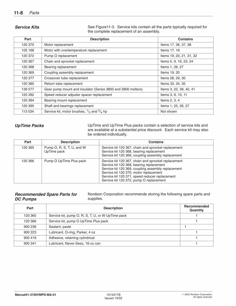
Parts11-8
� 2002 Nordson CorporationAll rights reserved
1015471BIssued 10/02
Manual41-3700VMPD-MA-01
See Figure11-3. Service kits contain all the parts typically required forthe complete replacement of an assembly.
Part Description Contains
120 370 Motor replacement Items 17, 36, 37, 38
105 168 Motor with overtemperature replacement Items 17, 18
120 372 Pump O replacement Items 19, 20, 21, 31, 32
120 367 Chain and sprocket replacement Items 5, 9, 16, 23, 24
120 368 Bearing replacement Items 1, 26, 27
120 369 Coupling assembly replacement Items 19, 20
120 377 Crossover tube replacement Items 28, 29, 30
120 380 Return tube replacement Items 33, 34, 35
139 577 Gear pump mount and insulator (Series 3800 and 3900 melters) Items 3, 22, 39, 40, 41
120 392 Speed reducer adjuster spacer replacement Items 3, 8, 10, 11
120 394 Bearing mount replacement Items 2, 3, 4
120 395 Shaft and bearings replacement Items 1, 25, 26, 27
113 034 Service kit, motor brushes, 1/2 and 3/4 hp Not shown
UpTime and UpTime Plus packs contain a selection of service kits andare available at a substantial price discount. Each service kit may alsobe ordered individually.
Part Description Contains
120 365 Pump O, R, S, T, U, and WUpTime pack
Service kit 120 367, chain and sprocket replacementService kit 120 368, bearing replacementService kit 120 369, coupling assembly replacement
120 366 Pump O UpTime Plus pack Service kit 120 367, chain and sprocket replacementService kit 120 368, bearing replacementService kit 120 369, coupling assembly replacementService kit 120 370, motor replacementService kit 120 371, speed reducer replacementService kit 120 372, pump O replacement
Nordson Corporation recommends storing the following spare parts andsupplies.
Part Description RecommendedQuantity
120 365 Service kit, pump O, R, S, T, U, or W UpTime pack 1
120 366 Service kit, pump O UpTime Plus pack 1
900 236 Sealant, paste 1
900 223 Lubricant, O-ring, Parker, 4 oz 1
900 419 Adhesive, retaining cylindrical 1
900 341 Lubricant, Never-Seez, 16-oz can 1
Service Kits
UpTime Packs
Recommended Spare Parts forDC Pumps
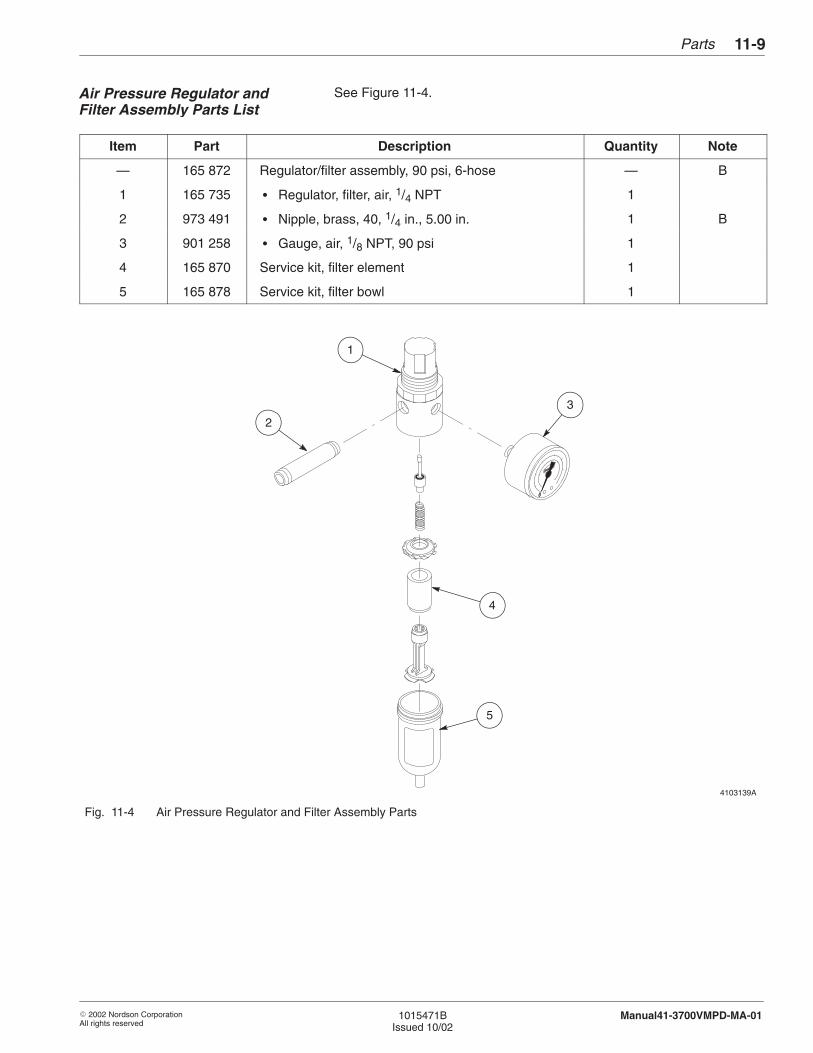
Parts 11-9
� 2002 Nordson CorporationAll rights reserved
1015471BIssued 10/02
Manual41-3700VMPD-MA-01
See Figure 11-4.
Item Part Description Quantity Note
— 165 872 Regulator/filter assembly, 90 psi, 6-hose — B
1 165 735 � Regulator, filter, air, 1/4 NPT 1
2 973 491 � Nipple, brass, 40, 1/4 in., 5.00 in. 1 B
3 901 258 � Gauge, air, 1/8 NPT, 90 psi 1
4 165 870 Service kit, filter element 1
5 165 878 Service kit, filter bowl 1
4103139A
1
2
3
4
5
Fig. 11-4 Air Pressure Regulator and Filter Assembly Parts
Air Pressure Regulator andFilter Assembly Parts List
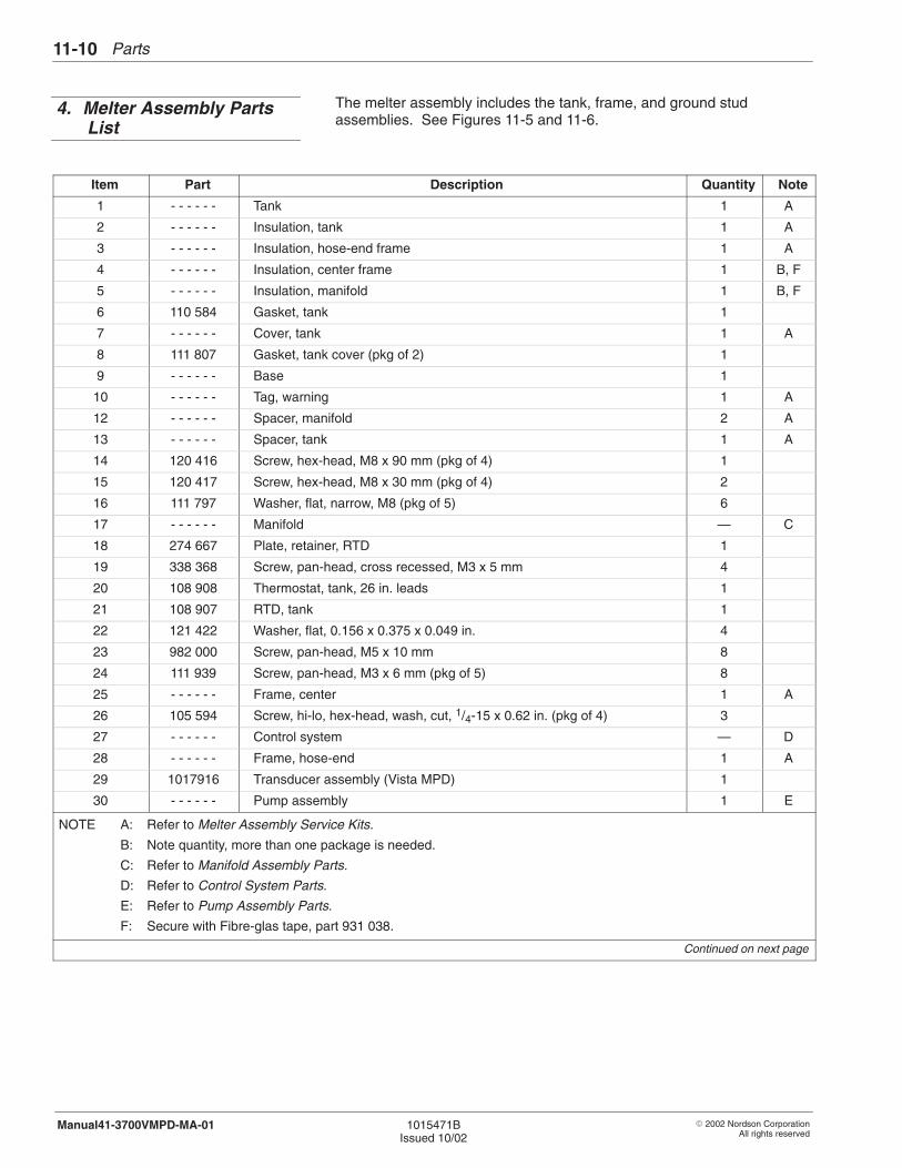
Parts11-10
� 2002 Nordson CorporationAll rights reserved
1015471BIssued 10/02
Manual41-3700VMPD-MA-01
The melter assembly includes the tank, frame, and ground studassemblies. See Figures 11-5 and 11-6.
Item Part Description Quantity Note
1 - - - - - - Tank 1 A
2 - - - - - - Insulation, tank 1 A
3 - - - - - - Insulation, hose-end frame 1 A
4 - - - - - - Insulation, center frame 1 B, F
5 - - - - - - Insulation, manifold 1 B, F
6 110 584 Gasket, tank 1
7 - - - - - - Cover, tank 1 A
8 111 807 Gasket, tank cover (pkg of 2) 1
9 - - - - - - Base 1
10 - - - - - - Tag, warning 1 A
12 - - - - - - Spacer, manifold 2 A
13 - - - - - - Spacer, tank 1 A
14 120 416 Screw, hex-head, M8 x 90 mm (pkg of 4) 1
15 120 417 Screw, hex-head, M8 x 30 mm (pkg of 4) 2
16 111 797 Washer, flat, narrow, M8 (pkg of 5) 6
17 - - - - - - Manifold — C
18 274 667 Plate, retainer, RTD 1
19 338 368 Screw, pan-head, cross recessed, M3 x 5 mm 4
20 108 908 Thermostat, tank, 26 in. leads 1
21 108 907 RTD, tank 1
22 121 422 Washer, flat, 0.156 x 0.375 x 0.049 in. 4
23 982 000 Screw, pan-head, M5 x 10 mm 8
24 111 939 Screw, pan-head, M3 x 6 mm (pkg of 5) 8
25 - - - - - - Frame, center 1 A
26 105 594 Screw, hi-lo, hex-head, wash, cut, 1/4-15 x 0.62 in. (pkg of 4) 3
27 - - - - - - Control system — D
28 - - - - - - Frame, hose-end 1 A
29 1017916 Transducer assembly (Vista MPD) 1
30 - - - - - - Pump assembly 1 E
NOTE A: Refer to Melter Assembly Service Kits.
B: Note quantity, more than one package is needed.
C: Refer to Manifold Assembly Parts.
D: Refer to Control System Parts.
E: Refer to Pump Assembly Parts.
F: Secure with Fibre-glas tape, part 931 038.
Continued on next page
4. Melter Assembly PartsList
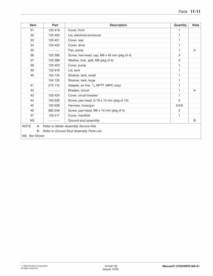
Parts 11-11
� 2002 Nordson CorporationAll rights reserved
1015471BIssued 10/02
Manual41-3700VMPD-MA-01
Item NoteQuantityDescriptionPart
31 120 419 Cover, front 1
32 120 420 Lid, electrical enclosure 1
33 120 421 Cover, rear 1
34 120 422 Cover, drive 1
35 - - - - - - Pan, pump 1 A
36 120 390 Screw, hex-head, cap, M8 x 40 mm (pkg of 4) 3
37 120 388 Washer, lock, split, M8 (pkg of 4) 3
38 120 423 Cover, pump 1
39 133 916 Lid, tank 1
40 104 134 Strainer, tank, small 1
104 135 Strainer, tank, large 1
41 275 115 Adapter, air line, 1/4 NPTF (MPC only) 1
42 - - - - - - Breaker, circuit 1 A
43 120 424 Cover, circuit breaker 1
44 105 626 Screw, pan-head, 6-19 x 10 mm (pkg of 10) 5
45 105 628 Harness, hose/gun 2/4/6
46 982 246 Screw, pan-head, M6 x 10 mm (pkg of 4) 2
47 120 411 Cover, manifold 1
NS - - - - - - Ground stud assembly B
NOTE A: Refer to Melter Assembly Service Kits.
B: Refer to Ground Stud Assembly Parts List.
NS: Not Shown
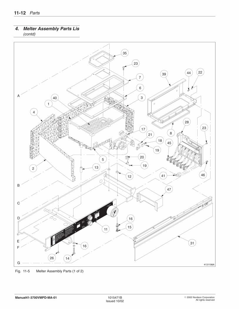
Parts11-12
� 2002 Nordson CorporationAll rights reserved
1015471BIssued 10/02
Manual41-3700VMPD-MA-01
4131198A
15
16
16
11
26
31
C
D
G
21
18
19
19
45
28
23
41 46
47
13
ÎÎÎÎÎÎÎÎÎÎÎÎÎÎÎÎÎÎ
ÌÌÌÌÌÌÌÌÌÌÌÌÌÌÌÌÌÌÌÌÌÌÌÌÌÌÌÌÌÌÌÌÌÌÌÌÌÌÌÌÌÌ
ÏÏÏÏÏÏÏÏÏÏÏÏÏÏÏ
ÏÏÏÏÏÏÏÏÏÏÏÏÏÏÏÏÏÏÏÏÏÏÏÏÏÏÏÏÏÏÏÏÏÏÏÏÏÏÏÏÏÏÏÏÏÏÏÏÏ
ÌÌÌÌÌÌÌÌÌÌ
ÎÎÎÎÎÎÎÎÎÎÎÎÎÎÎÎÎÎÏÏÏÏ
ÏÏÏÏÏÏÏÏÏÏÏÏÏÏÏÏ
ÎÎÎÎÎÎÎÎÎÎÎÎÎÎÎÎÎÎÎÎÎÎÎÎÎÎÎÎÎÎÎÎÎÎÎÎÎÎÎÎÎÎÎÎÎÎÎÎÎÎÎÎÎÎÎÎ
ÏÏÏÏÏÏÏÏÏÏÏÏÏÏÏÏÏÏÏÏÏÏÏÏÏÏÏÏÏÏÏÏÏÏÏÏÏÏÏÏ
ÌÌÌÌÌÌÌÌÌÌÌÌ
ÎÎÎÎÎÎÎÎÎÎÎÎÎÎÎ
ÏÏÏÏÏÏÏÏÏÏÎÎ
ÌÌÌÌÌÌÌÌÌÌÌÌÌÌÌÌÌÌÌÌ
ÏÏÏÏÏÏÏÏÏÏÏÏ
35
23
7
6
3
17
5
40
1
4
2
39 44 22
12
14
A
B
8
20
E
F
Fig. 11-5 Melter Assembly Parts (1 of 2)
4. Melter Assembly Parts Lis(contd)
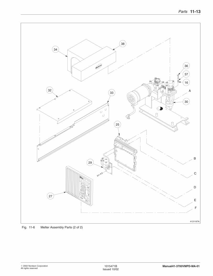
Parts 11-13
� 2002 Nordson CorporationAll rights reserved
1015471BIssued 10/02
Manual41-3700VMPD-MA-01
4131197A
36
38
A
B
C
D
E
F
37
16
30
3233
25
29
27
34
Fig. 11-6 Melter Assembly Parts (2 of 2)
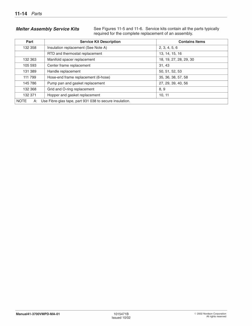
Parts11-14
� 2002 Nordson CorporationAll rights reserved
1015471BIssued 10/02
Manual41-3700VMPD-MA-01
See Figures 11-5 and 11-6. Service kits contain all the parts typicallyrequired for the complete replacement of an assembly.
Part Service Kit Description Contains Items
132 358 Insulation replacement (See Note A) 2, 3, 4, 5, 6
RTD and thermostat replacement 13, 14, 15, 16
132 363 Manifold spacer replacement 18, 19, 27, 28, 29, 30
105 593 Center frame replacement 31, 43
131 389 Handle replacement 50, 51, 52, 53
111 799 Hose-end frame replacement (6-hose) 35, 36, 38, 57, 58
145 786 Pump pan and gasket replacement 27, 29, 39, 40, 56
132 368 Grid and O-ring replacement 8, 9
132 371 Hopper and gasket replacement 10, 11
NOTE A: Use Fibre-glas tape, part 931 038 to secure insulation.
Melter Assembly Service Kits
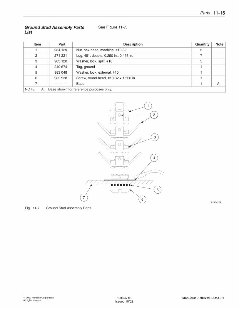
Parts 11-15
� 2002 Nordson CorporationAll rights reserved
1015471BIssued 10/02
Manual41-3700VMPD-MA-01
See Figure 11-7.
Item Part Description Quantity Note
1 984 129 Nut, hex-head, machine, #10-32 5
2 271 221 Lug, 45�, double, 0.250 in., 0.438 in. 7
3 983 120 Washer, lock, split, #10 5
4 240 674 Tag, ground 1
5 983 048 Washer, lock, external, #10 1
6 982 938 Screw, round-head, #10-32 x 1.500 in. 1
7 - - - - - - Base 1 A
NOTE A: Base shown for reference purposes only.
4130420A
ËËËËËËËË
1
2
3
4
5
7 6
Fig. 11-7 Ground Stud Assembly Parts
Ground Stud Assembly PartsList
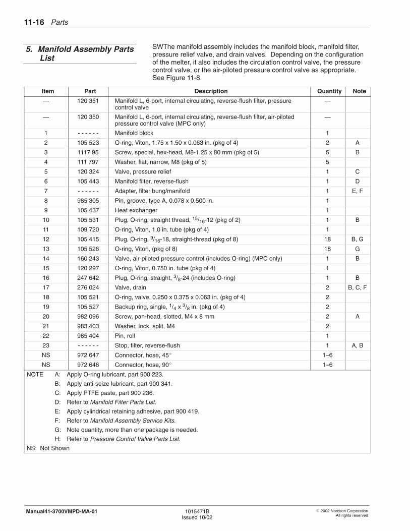
Parts11-16
� 2002 Nordson CorporationAll rights reserved
1015471BIssued 10/02
Manual41-3700VMPD-MA-01
SWThe manifold assembly includes the manifold block, manifold filter,pressure relief valve, and drain valves. Depending on the configurationof the melter, it also includes the circulation control valve, the pressurecontrol valve, or the air-piloted pressure control valve as appropriate.See Figure 11-8.
Item Part Description Quantity Note
— 120 351 Manifold L, 6-port, internal circulating, reverse-flush filter, pressurecontrol valve
—
— 120 350 Manifold L, 6-port, internal circulating, reverse-flush filter, air-pilotedpressure control valve (MPC only)
—
1 - - - - - - Manifold block 1
2 105 523 O-ring, Viton, 1.75 x 1.50 x 0.063 in. (pkg of 4) 2 A
3 1117 95 Screw, special, hex-head, M8-1.25 x 80 mm (pkg of 5) 5 B
4 111 797 Washer, flat, narrow, M8 (pkg of 5) 5
5 120 324 Valve, pressure relief 1 C
6 105 443 Manifold filter, reverse-flush 1 D
7 - - - - - - Adapter, filter bung/manifold 1 E, F
8 985 305 Pin, groove, type A, 0.078 x 0.500 in. 1
9 105 437 Heat exchanger 1
10 105 531 Plug, O-ring, straight thread, 15/16-12 (pkg of 2) 1 B
11 109 720 O-ring, Viton, 1.0 in. tube (pkg of 4) 1
12 105 415 Plug, O-ring, 9/16-18, straight-thread (pkg of 8) 18 B, G
13 105 526 O-ring, Viton, (pkg of 8) 18 G
14 160 243 Valve, air-piloted pressure control (includes O-ring) (MPC only) 1 B
15 120 297 O-ring, Viton, 0.750 in. tube (pkg of 4) 1
16 247 642 Plug, O-ring, straight, 3/8-24 (includes O-ring) 1 B
17 276 024 Valve, drain 2 B, C, F
18 105 521 O-ring, valve, 0.250 x 0.375 x 0.063 in. (pkg of 4) 2
19 105 527 Backup ring, single, 1/4 x 3/8 in. (pkg of 4) 2
20 982 096 Screw, pan-head, slotted, M4 x 8 mm 2 A
21 983 403 Washer, lock, split, M4 2
22 985 404 Pin, roll 1
23 - - - - - - Stop, filter, reverse-flush 1 A, B
NS 972 647 Connector, hose, 45� 1–6
NS 972 646 Connector, hose, 90� 1–6
NOTE A: Apply O-ring lubricant, part 900 223.
B: Apply anti-seize lubricant, part 900 341.
C: Apply PTFE paste, part 900 236.
D: Refer to Manifold Filter Parts List.
E: Apply cylindrical retaining adhesive, part 900 419.
F: Refer to Manifold Assembly Service Kits.
G: Note quantity, more than one package is needed.
H: Refer to Pressure Control Valve Parts List.
NS: Not Shown
5. Manifold Assembly PartsList
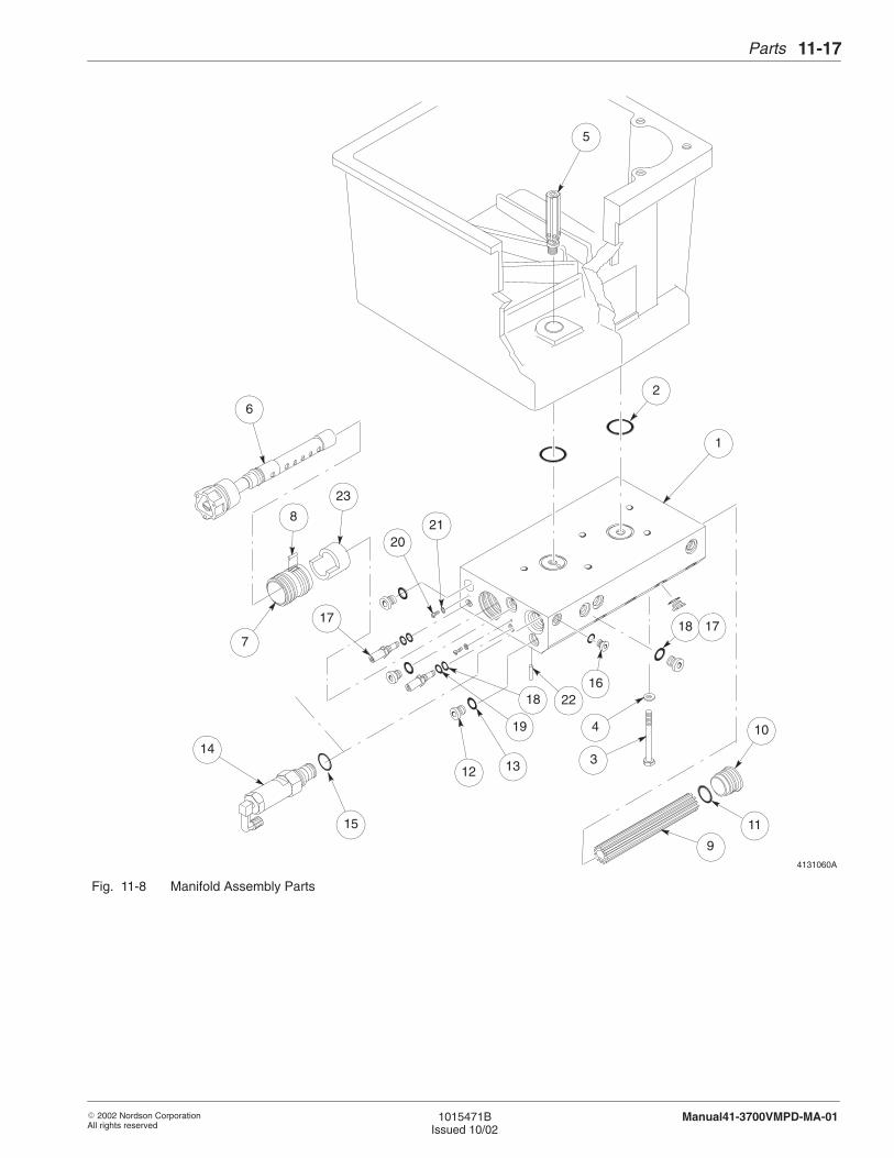
Parts 11-17
� 2002 Nordson CorporationAll rights reserved
1015471BIssued 10/02
Manual41-3700VMPD-MA-01
4131060A
6
218
7
13
11
18
4
16
1
2
17
3
10
9
23
20
12
17
15
18
19
5
22
14
Fig. 11-8 Manifold Assembly Parts
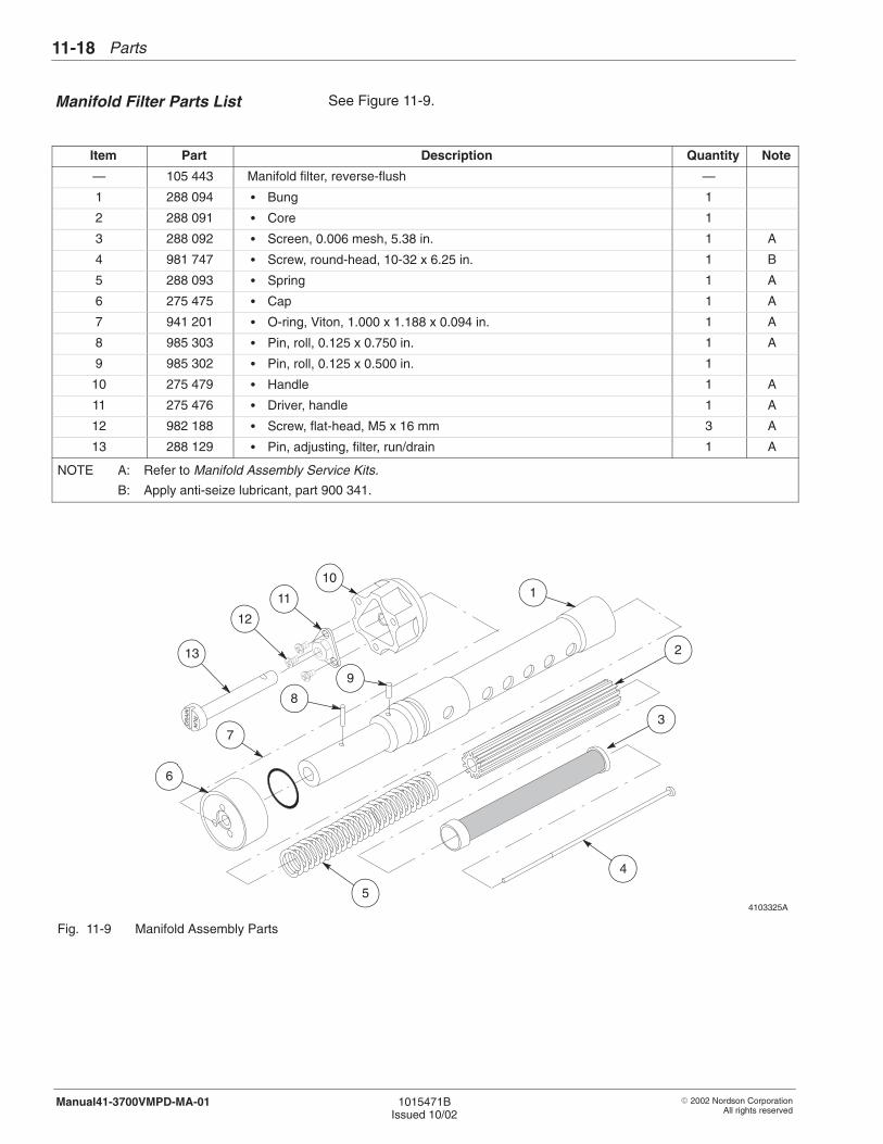
Parts11-18
� 2002 Nordson CorporationAll rights reserved
1015471BIssued 10/02
Manual41-3700VMPD-MA-01
See Figure 11-9.
Item Part Description Quantity Note
— 105 443 Manifold filter, reverse-flush —
1 288 094 � Bung 1
2 288 091 � Core 1
3 288 092 � Screen, 0.006 mesh, 5.38 in. 1 A
4 981 747 � Screw, round-head, 10-32 x 6.25 in. 1 B
5 288 093 � Spring 1 A
6 275 475 � Cap 1 A
7 941 201 � O-ring, Viton, 1.000 x 1.188 x 0.094 in. 1 A
8 985 303 � Pin, roll, 0.125 x 0.750 in. 1 A
9 985 302 � Pin, roll, 0.125 x 0.500 in. 1
10 275 479 � Handle 1 A
11 275 476 � Driver, handle 1 A
12 982 188 � Screw, flat-head, M5 x 16 mm 3 A
13 288 129 � Pin, adjusting, filter, run/drain 1 A
NOTE A: Refer to Manifold Assembly Service Kits.
B: Apply anti-seize lubricant, part 900 341.
4103325A
10
11
12
13
6
7
8
9
1
5
4
3
2
Fig. 11-9 Manifold Assembly Parts
Manifold Filter Parts List
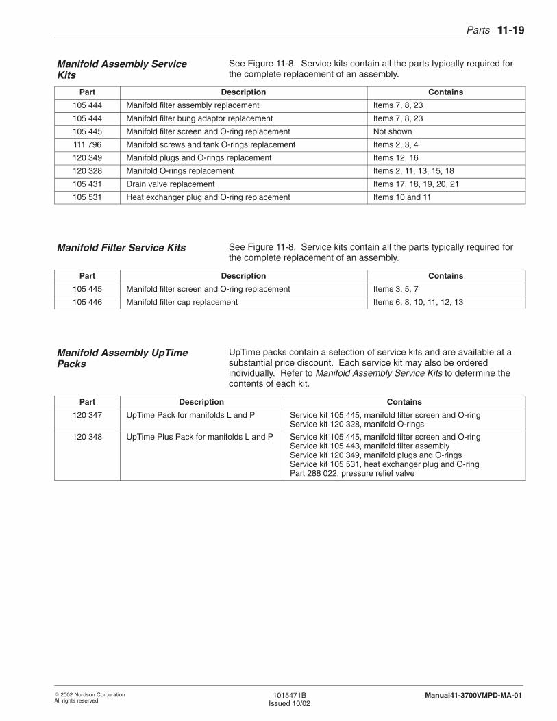
Parts 11-19
� 2002 Nordson CorporationAll rights reserved
1015471BIssued 10/02
Manual41-3700VMPD-MA-01
See Figure 11-8. Service kits contain all the parts typically required forthe complete replacement of an assembly.
Part Description Contains
105 444 Manifold filter assembly replacement Items 7, 8, 23
105 444 Manifold filter bung adaptor replacement Items 7, 8, 23
105 445 Manifold filter screen and O-ring replacement Not shown
111 796 Manifold screws and tank O-rings replacement Items 2, 3, 4
120 349 Manifold plugs and O-rings replacement Items 12, 16
120 328 Manifold O-rings replacement Items 2, 11, 13, 15, 18
105 431 Drain valve replacement Items 17, 18, 19, 20, 21
105 531 Heat exchanger plug and O-ring replacement Items 10 and 11
See Figure 11-8. Service kits contain all the parts typically required forthe complete replacement of an assembly.
Part Description Contains
105 445 Manifold filter screen and O-ring replacement Items 3, 5, 7
105 446 Manifold filter cap replacement Items 6, 8, 10, 11, 12, 13
UpTime packs contain a selection of service kits and are available at asubstantial price discount. Each service kit may also be orderedindividually. Refer to Manifold Assembly Service Kits to determine thecontents of each kit.
Part Description Contains
120 347 UpTime Pack for manifolds L and P Service kit 105 445, manifold filter screen and O-ringService kit 120 328, manifold O-rings
120 348 UpTime Plus Pack for manifolds L and P Service kit 105 445, manifold filter screen and O-ringService kit 105 443, manifold filter assemblyService kit 120 349, manifold plugs and O-ringsService kit 105 531, heat exchanger plug and O-ring Part 288 022, pressure relief valve
Manifold Assembly ServiceKits
Manifold Filter Service Kits
Manifold Assembly UpTimePacks
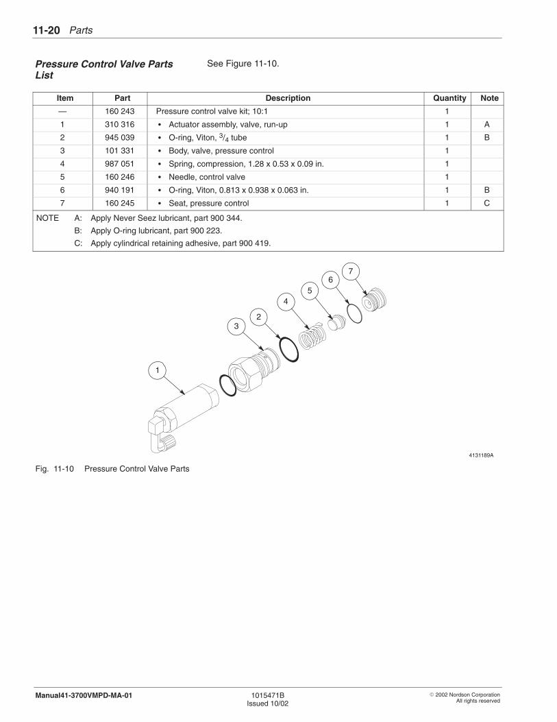
Parts11-20
� 2002 Nordson CorporationAll rights reserved
1015471BIssued 10/02
Manual41-3700VMPD-MA-01
See Figure 11-10.
Item Part Description Quantity Note
— 160 243 Pressure control valve kit; 10:1 1
1 310 316 � Actuator assembly, valve, run-up 1 A
2 945 039 � O-ring, Viton, 3/4 tube 1 B
3 101 331 � Body, valve, pressure control 1
4 987 051 � Spring, compression, 1.28 x 0.53 x 0.09 in. 1
5 160 246 � Needle, control valve 1
6 940 191 � O-ring, Viton, 0.813 x 0.938 x 0.063 in. 1 B
7 160 245 � Seat, pressure control 1 C
NOTE A: Apply Never Seez lubricant, part 900 344.
B: Apply O-ring lubricant, part 900 223.
C: Apply cylindrical retaining adhesive, part 900 419.
4131189A
1
23
45
67
Fig. 11-10 Pressure Control Valve Parts
Pressure Control Valve PartsList

Parts 11-21
� 2002 Nordson CorporationAll rights reserved
1015471BIssued 10/02
Manual41-3700VMPD-MA-01
Nordson Corporation recommends storing the following spare parts andsupplies.
Part Description RecommendedQuantity
120 347 UpTime Pack, manifolds L and P 1
120 348 UpTime Plus pack, manifolds L and P 1
900 236 Sealant, paste 1
900 223 Lubricant, O-ring, Parker, 4 oz 1
900 419 Adhesive, retaining cylindrical 1
900 341 Lubricant, Never-Seez, 16-oz can 1
Nordson offers two test plugs that simplify the troubleshooting of RTDfaults. These test plugs help you quickly and easily determine whetherthe problem is a gun, hose, or tank RTD problem or a Vista controllerproblem.
Part Description Quantity Note
326 975 Service kit, test plugs, Vista/3000 —
- - - - - - Plug, test, hose/gun, 3000 1
- - - - - - Plug, test, Vista 1
If your melter is affected by electrical noise, install a line filter on eachinput power line to the melter. Connect the filter line-to-line. For athree-phase system, order three filters.
Part Description Quantity Note
332 182 RC snubber (line filter) 1
Recommended Spare Parts
Hose/Gun Test Plugs
Line Filter

Parts11-22
� 2002 Nordson CorporationAll rights reserved
1015471BIssued 10/02
Manual41-3700VMPD-MA-01
� 2002 Nordson CorporationAll rights reserved
1015471BIssued 10/02
Manual41-3700VMPD-MA-01
Section 12
Specifications

Specifications12-0
� 2002 Nordson CorporationAll rights reserved
1015471BIssued 10/02
Manual41-3700VMPD-MA-01
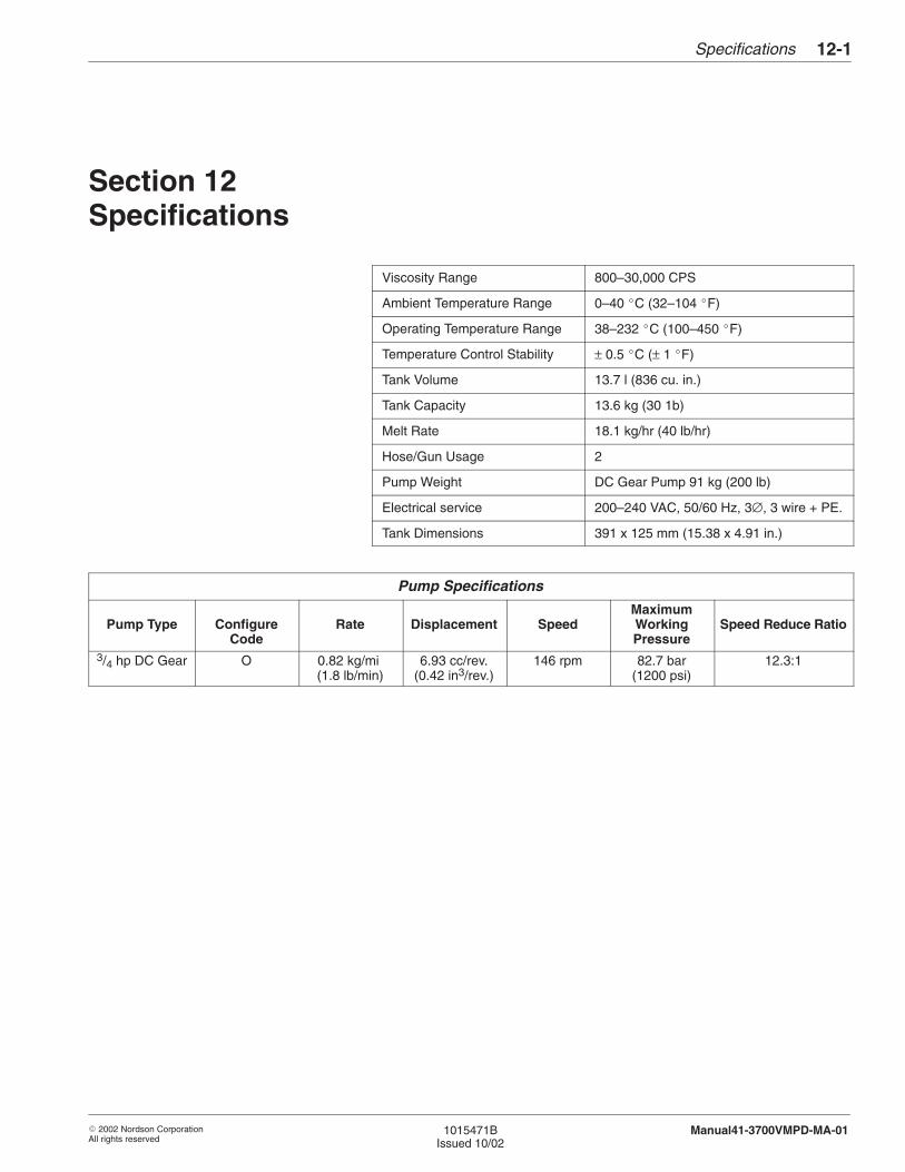
Specifications 12-1
� 2002 Nordson CorporationAll rights reserved
1015471BIssued 10/02
Manual41-3700VMPD-MA-01
Section 12Specifications
Viscosity Range 800–30,000 CPS
Ambient Temperature Range 0–40 �C (32–104 �F)
Operating Temperature Range 38–232 �C (100–450 �F)
Temperature Control Stability ± 0.5 �C (± 1 �F)
Tank Volume 13.7 l (836 cu. in.)
Tank Capacity 13.6 kg (30 1b)
Melt Rate 18.1 kg/hr (40 lb/hr)
Hose/Gun Usage 2
Pump Weight DC Gear Pump 91 kg (200 lb)
Electrical service 200–240 VAC, 50/60 Hz, 3∅, 3 wire + PE.
Tank Dimensions 391 x 125 mm (15.38 x 4.91 in.)
Pump Specifications
Pump Type ConfigureCode
Rate Displacement SpeedMaximumWorkingPressure
Speed Reduce Ratio
3/4 hp DC Gear O 0.82 kg/mi (1.8 lb/min)
6.93 cc/rev.(0.42 in3/rev.)
146 rpm 82.7 bar(1200 psi)
12.3:1
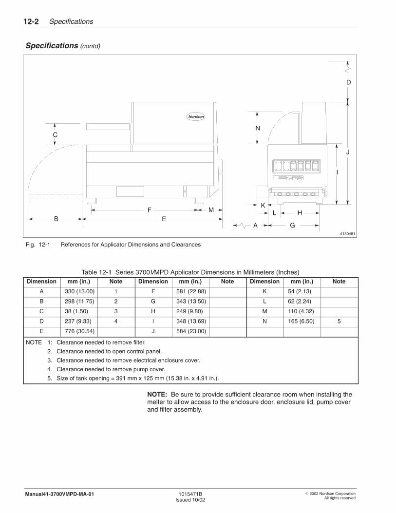
Specifications12-2
� 2002 Nordson CorporationAll rights reserved
1015471BIssued 10/02
Manual41-3700VMPD-MA-01
Specifications (contd)
4130481
B
C
D
EF H
I
J
LM
G
K
A
N
Fig. 12-1 References for Applicator Dimensions and Clearances
Table 12-1 Series 3700VMPD Applicator Dimensions in Millimeters (Inches)Dimension mm (in.) Note Dimension mm (in.) Note Dimension mm (in.) Note
A 330 (13.00) 1 F 581 (22.88) K 54 (2.13)
B 298 (11.75) 2 G 343 (13.50) L 62 (2.24)
C 38 (1.50) 3 H 249 (9.80) M 110 (4.32)
D 237 (9.33) 4 I 348 (13.69) N 165 (6.50) 5
E 776 (30.54) J 584 (23.00)
NOTE 1: Clearance needed to remove filter.
2. Clearance needed to open control panel.
3. Clearance needed to remove electrical enclosure cover.
4. Clearance needed to remove pump cover.
5. Size of tank opening = 391 mm x 125 mm (15.38 in. x 4.91 in.).
NOTE: Be sure to provide sufficient clearance room when installing themelter to allow access to the enclosure door, enclosure lid, pump coverand filter assembly.
Specifications 12-3
� 2002 Nordson CorporationAll rights reserved
1015471BIssued 10/02
Manual41-3700VMPD-MA-01
When you connect hoses and guns to your hot melt unit, you must makesure the electrical power requirements of those hoses and guns do notexceed the maximum wattages allowed for your system. Exceeding theallowed maximum wattage can damage your equipment or keep yoursystem from functioning properly.
For every Series 3000V system, there are three maximum wattages youmust not exceed:
� The single-component maximum wattage: the wattage of anysingle hose or gun connected to your melter must not exceed thiswattage.
� The hose/gun pair maximum wattage: the wattage of any hoseand gun (hose/gun pair) connected to your melter must not exceedthis wattage.
� The total hose/gun maximum wattage: the wattage of all hosesand guns connected to your melter must not exceed this wattage.
To make sure your system does not exceed any of these maximumwattages, someone (either you or your Nordson representative) mustcalculate the hose/gun capacity for your system. If your Nordsonrepresentative has already made this calculation for the actual hoses andguns you plan to use, you do not need to repeat the calculation now.However, you must make this calculation
� if the hose/gun capacity has not been calculated for your system
� if you have reconfigured your system since the calculations weremade
� whenever you add new hoses or guns to an existing system
� whenever you replace an existing hose with a longer one or anexisting gun with a larger one
1. Introduction
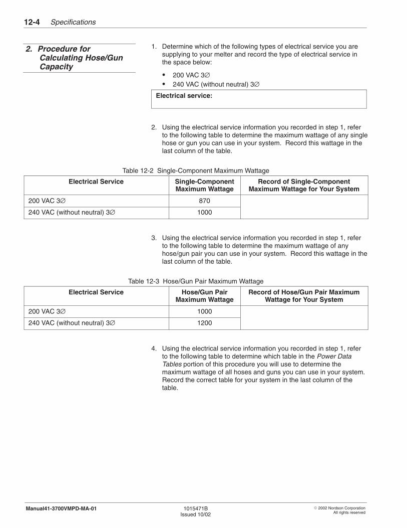
Specifications12-4
� 2002 Nordson CorporationAll rights reserved
1015471BIssued 10/02
Manual41-3700VMPD-MA-01
1. Determine which of the following types of electrical service you aresupplying to your melter and record the type of electrical service inthe space below:
� 200 VAC 3∅� 240 VAC (without neutral) 3∅
Electrical service:
2. Using the electrical service information you recorded in step 1, referto the following table to determine the maximum wattage of any singlehose or gun you can use in your system. Record this wattage in thelast column of the table.
Table 12-2 Single-Component Maximum Wattage
Electrical Service Single-ComponentMaximum Wattage
Record of Single-ComponentMaximum Wattage for Your System
200 VAC 3∅ 870
240 VAC (without neutral) 3∅ 1000
3. Using the electrical service information you recorded in step 1, referto the following table to determine the maximum wattage of anyhose/gun pair you can use in your system. Record this wattage in thelast column of the table.
Table 12-3 Hose/Gun Pair Maximum Wattage
Electrical Service Hose/Gun PairMaximum Wattage
Record of Hose/Gun Pair MaximumWattage for Your System
200 VAC 3∅ 1000
240 VAC (without neutral) 3∅ 1200
4. Using the electrical service information you recorded in step 1, referto the following table to determine which table in the Power DataTables portion of this procedure you will use to determine themaximum wattage of all hoses and guns you can use in your system.Record the correct table for your system in the last column of thetable.
2. Procedure forCalculating Hose/GunCapacity

Specifications 12-5
� 2002 Nordson CorporationAll rights reserved
1015471BIssued 10/02
Manual41-3700VMPD-MA-01
Table 12-4 Correct Table in Power Data Tables for Your System
Electrical Service Table in Power DataTables
Record of Correct Table in Power DataTables for Your System
200 VAC 3∅ Table 12-8
240 VAC (without neutral) 3∅ Table 12-9
5. Using the information you recorded in steps 3 and 4, find the correctrow in the correct table (which you recorded in step 4) based on themodel of your melter and the type of pump your melter has. Thenfind the correct sub-row within the row based on the hose/gunelectrical capacity of your system (2, 4, 6) ). Then read across thetable to the column titled Total Hose/Gun Maximum Wattage todetermine the maximum wattage for your system’s hoses and guns.Record the total hose/gun maximum wattage for your system in thespace below:
Table 12-5 Total Hose/Gun Maximum Wattage
Record of Total Hose/Gun Maximum Wattagefor Your System
NOTE: You do not need to use the data in the remaining columns ofthe table. This data is for reference only.
6. In the table below, record the total maximum wattages you recordedin Tables 12-2, 12-3, and 12-5.
Table 12-6 Maximum Wattages for Your System
Type of Maximum Wattage Refer to… Record ofMaximum
Wattage forYour System
Single-component maximum wattage Table 12-2
Hose/gun pair maximum wattage Table 12-3
Total hose/gun maximum wattage Table 12-5
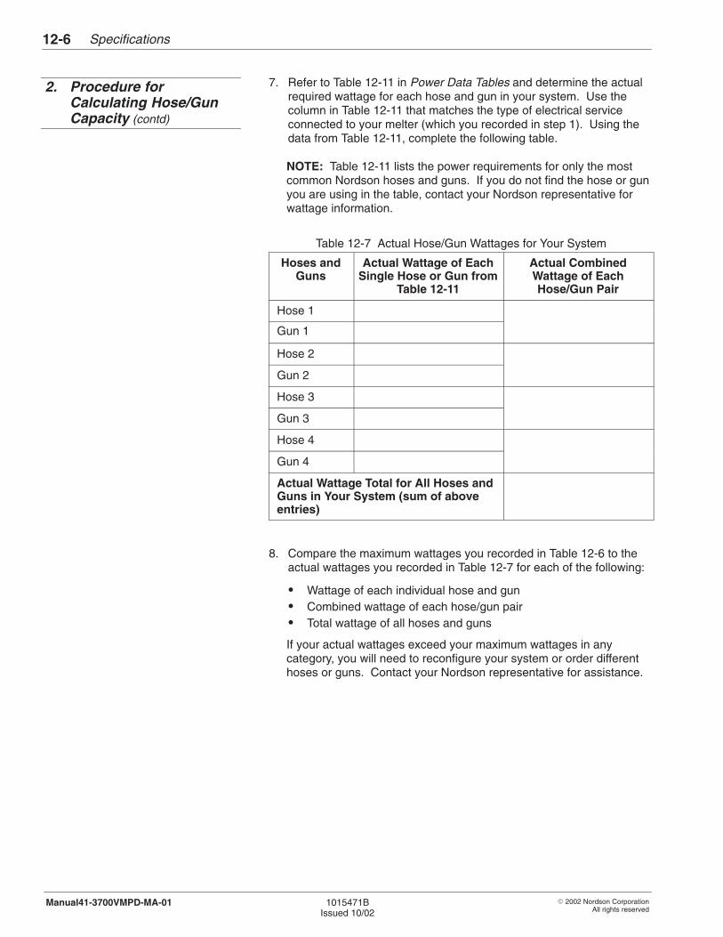
Specifications12-6
� 2002 Nordson CorporationAll rights reserved
1015471BIssued 10/02
Manual41-3700VMPD-MA-01
7. Refer to Table 12-11 in Power Data Tables and determine the actualrequired wattage for each hose and gun in your system. Use thecolumn in Table 12-11 that matches the type of electrical serviceconnected to your melter (which you recorded in step 1). Using thedata from Table 12-11, complete the following table.
NOTE: Table 12-11 lists the power requirements for only the mostcommon Nordson hoses and guns. If you do not find the hose or gunyou are using in the table, contact your Nordson representative forwattage information.
Table 12-7 Actual Hose/Gun Wattages for Your System
Hoses andGuns
Actual Wattage of EachSingle Hose or Gun from
Table 12-11
Actual CombinedWattage of EachHose/Gun Pair
Hose 1
Gun 1
Hose 2
Gun 2
Hose 3
Gun 3
Hose 4
Gun 4
Actual Wattage Total for All Hoses andGuns in Your System (sum of aboveentries)
8. Compare the maximum wattages you recorded in Table 12-6 to theactual wattages you recorded in Table 12-7 for each of the following:
� Wattage of each individual hose and gun� Combined wattage of each hose/gun pair� Total wattage of all hoses and guns
If your actual wattages exceed your maximum wattages in anycategory, you will need to reconfigure your system or order differenthoses or guns. Contact your Nordson representative for assistance.
2. Procedure forCalculating Hose/GunCapacity (contd)
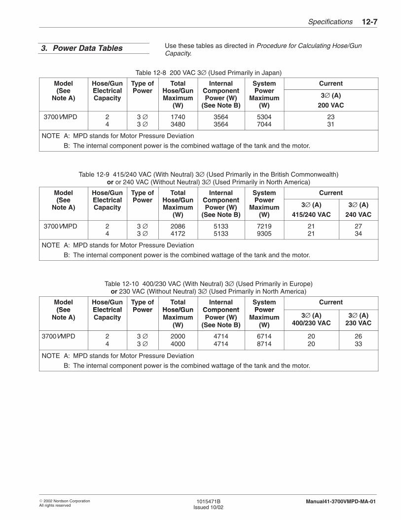
Specifications 12-7
� 2002 Nordson CorporationAll rights reserved
1015471BIssued 10/02
Manual41-3700VMPD-MA-01
Use these tables as directed in Procedure for Calculating Hose/GunCapacity.
Table 12-8 200 VAC 3∅ (Used Primarily in Japan)
Model(See
Hose/GunElectrical
Type ofPower
TotalHose/G n
InternalComponent
SystemPower
Current(See
Note A)ElectricalCapacity
Power Hose/GunMaximum
(W)
ComponentPower (W)
(See Note B)
PowerMaximum
(W)
3∅ (A)
200 VAC
3700VMPD 24
3 ∅3 ∅
17403480
35643564
53047044
2331
NOTE A: MPD stands for Motor Pressure Deviation
B: The internal component power is the combined wattage of the tank and the motor.
Table 12-9 415/240 VAC (With Neutral) 3∅ (Used Primarily in the British Commonwealth)or or 240 VAC (Without Neutral) 3∅ (Used Primarily in North America)
Model(See
Hose/GunElectrical
Type ofPower
TotalHose/G n
InternalComponent
SystemPower
Current(See
Note A)ElectricalCapacity
Power Hose/GunMaximum
(W)
ComponentPower (W)
(See Note B)
PowerMaximum
(W)
3∅ (A)
415/240 VAC
3∅ (A)
240 VAC
3700VMPD 24
3 ∅3 ∅
20864172
51335133
72199305
2121
2734
NOTE A: MPD stands for Motor Pressure Deviation
B: The internal component power is the combined wattage of the tank and the motor.
Table 12-10 400/230 VAC (With Neutral) 3∅ (Used Primarily in Europe)or 230 VAC (Without Neutral) 3∅ (Used Primarily in North America)
Model(See
Hose/GunElectrical
Type ofPower
TotalHose/G n
InternalComponent
SystemPower
Current(See
Note A)ElectricalCapacity
Power Hose/GunMaximum
(W)
ComponentPower (W)
(See Note B)
PowerMaximum
(W)3∅ (A)
400/230 VAC3∅ (A)
230 VAC
3700VMPD 24
3 ∅3 ∅
20004000
47144714
67148714
2020
2633
NOTE A: MPD stands for Motor Pressure Deviation
B: The internal component power is the combined wattage of the tank and the motor.
3. Power Data Tables
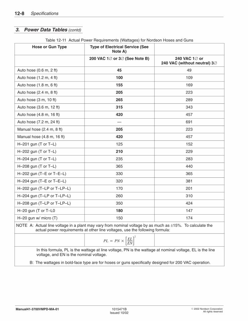
Specifications12-8
� 2002 Nordson CorporationAll rights reserved
1015471BIssued 10/02
Manual41-3700VMPD-MA-01
Table 12-11 Actual Power Requirements (Wattages) for Nordson Hoses and Guns
Hose or Gun Type Type of Electrical Service (SeeNote A)
200 VAC 1� or 3� (See Note B) 240 VAC 1� or240 VAC (without neutral) 3�
Auto hose (0.6 m, 2 ft) 45 49
Auto hose (1.2 m, 4 ft) 100 109
Auto hose (1.8 m, 6 ft) 155 169
Auto hose (2.4 m, 8 ft) 205 223
Auto hose (3 m, 10 ft) 265 289
Auto hose (3.6 m, 12 ft) 315 343
Auto hose (4.8 m, 16 ft) 420 457
Auto hose (7.2 m, 24 ft) — 691
Manual hose (2.4 m, 8 ft) 205 223
Manual hose (4.8 m, 16 ft) 420 457
H–201 gun (T or T–L) 125 152
H–202 gun (T or T–L) 210 229
H–204 gun (T or T–L) 235 283
H–208 gun (T or T–L) 365 440
H–202 gun (T–E or T–E–L) 330 365
H–204 gun (T–E or T–E–L) 320 381
H–202 gun (T–LP or T–LP–L) 170 201
H–204 gun (T–LP or T–LP–L) 260 310
H–208 gun (T–LP or T–LP–L) 350 424
H–20 gun (T or T–L0 180 147
H–20 gun w/ micro (T) 150 174
NOTE A: Actual line voltage in a plant may vary from nominal voltage by as much as ±15%. To calculate theactual power requirements at other line voltages, use the following formula:
PL � PN � �ELEN�
2
In this formula, PL is the wattage at line voltage, PN is the wattage at nominal voltage, EL is the linevoltage, and EN is the nominal voltage.
B: The wattages in bold-face type are for hoses or guns specifically designed for 200 VAC operation.
3. Power Data Tables (contd)
� 2002 Nordson CorporationAll rights reserved
1015471BIssued 10/02
Manual41-3700-MPD-MA-01
Section 13
Glossary

Glossary13-0
� 2002 Nordson CorporationAll rights reserved
1015471BIssued 10/02
Manual41-3700-MPD-MA-01
Glossary 13-1
� 2002 Nordson CorporationAll rights reserved
1015471BIssued 10/02
Manual41-3700-MPD-MA-01
Section 13Glossary
Any material that can be used to adhere or “stick” one surface to another.
Fine threads of adhesive caused by incomplete transfer of the adhesivemass from applicator to substrate, followed by elongation of theconnecting bridges. May be caused by improper nozzle shutoff with ahigh viscosity adhesive.
That part of the hot melt system that is used to heat adhesive to itsrequired application temperature and pump it to the hose(s) and gun(s).It consists of a tank or reservoir, pump, filter, distribution manifold andtemperature controlled heating system.
An automatically actuated valve which is opened by fluid flow in onedirection and closed by flow in the opposite direction.
The width of an adhesive bead which has been deposited on a substrate.The measurement is taken before the bead has been flattened byadhering it to another surface.
See Heater Cartridge.
A non-replaceable heating element specifically shaped to provide auniform thermal profile in the heated object.
The degradation of a fluid that occurs as a result of time and exposure toatmospheric air and/or heat.
An electronic device that acts to shut down a powered AC circuit whencurrent draw (amps) exceeds some preselected value or when certainfault conditions exist.
A temperature control device that closes, completing an electronic circuitupon reaching a specific temperature.
The tube that connects the outlet port of a pump to the distributionmanifold of a hot melt applicator.
Adhesive
Angel Hair
Applicator
Ball Check Valve
Bead Thickness
Cartridge Heater
Cast-in Resistive HeatingElement
Charring in Tank
Circuit Breaker
Close-on-rise Thermostat
Crossover Tube
Glossary13-2
� 2002 Nordson CorporationAll rights reserved
1015471BIssued 10/02
Manual41-3700-MPD-MA-01
The time between when the gun is signaled to stop and when theadhesive flow actually does stop.
A pump that delivers material on both the upstroke and the downstroke.
A manufacturer’s statement of the maximum level of some externalcondition, such as water or dust level, that the enclosure is capable ofwithstanding.
A speed-sensing device which outputs a frequency of pulses proportionalto the measured line speed.
A spring-loaded triggering device for dispensing or depositing material.There are two basic types of guns, the manual gun which is actuated byhand and the automatic gun which is actuated by process controls.
That part of a filter assembly external to the unit to which the filteringelement is attached, or contained within the unit. It is also used foraccess or cleaning.
The amount of material flowing through the system per unit of time. Theamount may be expressed in gravimetric (weight) or volumetric terms.Examples: grams/minute, ml/min, lb/hour, gallons/hour.
A valve typically used to pressurize one side of a double acting cylinderwhile opening a exhaust path for the opposite side.
See Key-to-line.
A cross-linked, insoluble material which can form in a hot melt applicatorunder extended thermal stress.
A wire that connects all AC powered devices to earth ground.
The device that dispenses a material (adhesive) onto a substrate orproduct.
A replaceable resistive heating element, tubular in shape, designed to fitin a machined hole in the object to be heated.
The volume that is heated and thermally controlled by a single controldevice.
A container allowing non-melted adhesive to be supplied on a continuousbasis to a melt zone.
Drop-out Time
Dual-acting Piston Pump
Enclosure Rating
Encoder
Extrusion Gun
Filter Bung
Flow Rate
Four-way Air Valve
Gear-to-line
Gel
Ground Wire
Gun
Heater Cartridge
Heating Bong
Hopper
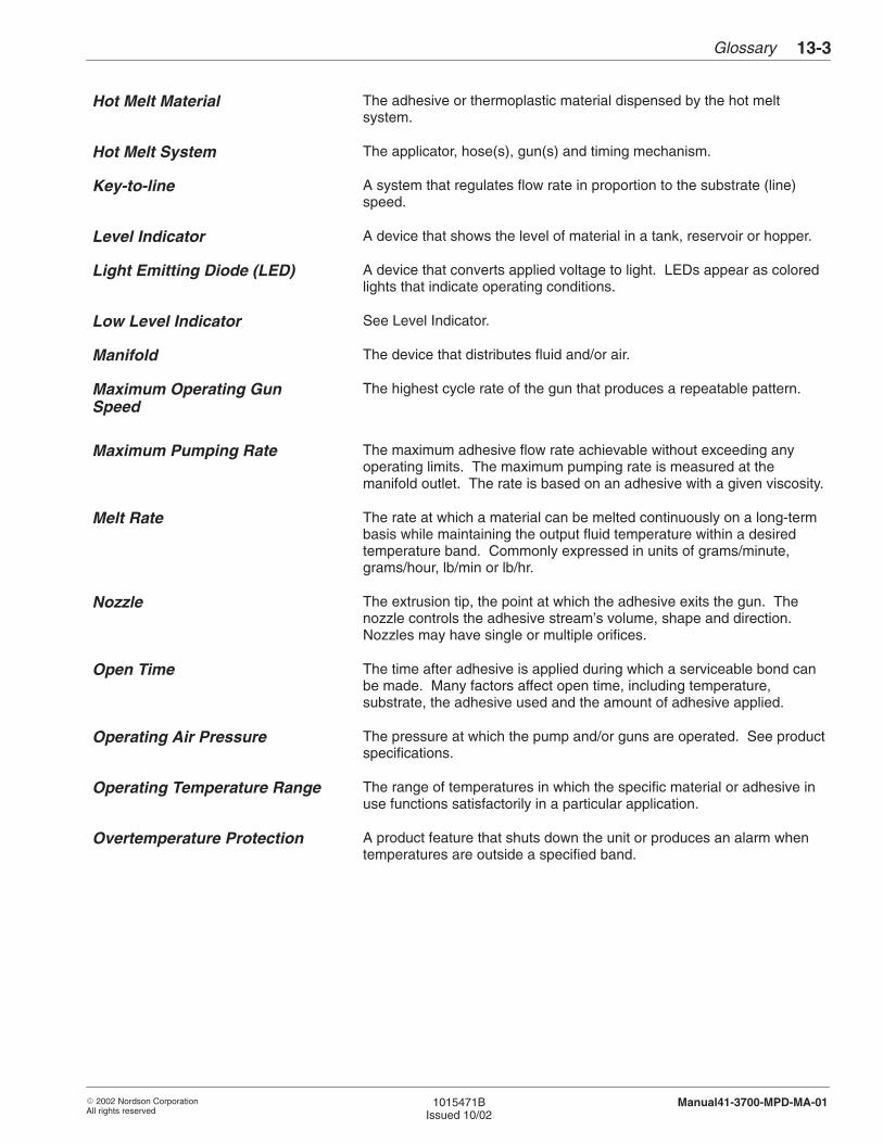
Glossary 13-3
� 2002 Nordson CorporationAll rights reserved
1015471BIssued 10/02
Manual41-3700-MPD-MA-01
The adhesive or thermoplastic material dispensed by the hot meltsystem.
The applicator, hose(s), gun(s) and timing mechanism.
A system that regulates flow rate in proportion to the substrate (line)speed.
A device that shows the level of material in a tank, reservoir or hopper.
A device that converts applied voltage to light. LEDs appear as coloredlights that indicate operating conditions.
See Level Indicator.
The device that distributes fluid and/or air.
The highest cycle rate of the gun that produces a repeatable pattern.
The maximum adhesive flow rate achievable without exceeding anyoperating limits. The maximum pumping rate is measured at themanifold outlet. The rate is based on an adhesive with a given viscosity.
The rate at which a material can be melted continuously on a long-termbasis while maintaining the output fluid temperature within a desiredtemperature band. Commonly expressed in units of grams/minute,grams/hour, lb/min or lb/hr.
The extrusion tip, the point at which the adhesive exits the gun. Thenozzle controls the adhesive stream’s volume, shape and direction.Nozzles may have single or multiple orifices.
The time after adhesive is applied during which a serviceable bond canbe made. Many factors affect open time, including temperature,substrate, the adhesive used and the amount of adhesive applied.
The pressure at which the pump and/or guns are operated. See productspecifications.
The range of temperatures in which the specific material or adhesive inuse functions satisfactorily in a particular application.
A product feature that shuts down the unit or produces an alarm whentemperatures are outside a specified band.
Hot Melt Material
Hot Melt System
Key-to-line
Level Indicator
Light Emitting Diode (LED)
Low Level Indicator
Manifold
Maximum Operating GunSpeed
Maximum Pumping Rate
Melt Rate
Nozzle
Open Time
Operating Air Pressure
Operating Temperature Range
Overtemperature Protection
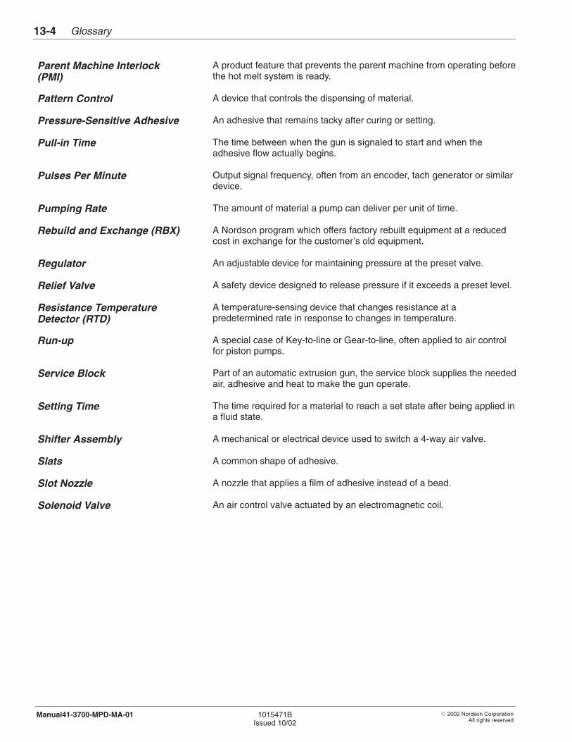
Glossary13-4
� 2002 Nordson CorporationAll rights reserved
1015471BIssued 10/02
Manual41-3700-MPD-MA-01
A product feature that prevents the parent machine from operating beforethe hot melt system is ready.
A device that controls the dispensing of material.
An adhesive that remains tacky after curing or setting.
The time between when the gun is signaled to start and when theadhesive flow actually begins.
Output signal frequency, often from an encoder, tach generator or similardevice.
The amount of material a pump can deliver per unit of time.
A Nordson program which offers factory rebuilt equipment at a reducedcost in exchange for the customer’s old equipment.
An adjustable device for maintaining pressure at the preset valve.
A safety device designed to release pressure if it exceeds a preset level.
A temperature-sensing device that changes resistance at apredetermined rate in response to changes in temperature.
A special case of Key-to-line or Gear-to-line, often applied to air controlfor piston pumps.
Part of an automatic extrusion gun, the service block supplies the neededair, adhesive and heat to make the gun operate.
The time required for a material to reach a set state after being applied ina fluid state.
A mechanical or electrical device used to switch a 4-way air valve.
A common shape of adhesive.
A nozzle that applies a film of adhesive instead of a bead.
An air control valve actuated by an electromagnetic coil.
Parent Machine Interlock(PMI)
Pattern Control
Pressure-Sensitive Adhesive
Pull-in Time
Pulses Per Minute
Pumping Rate
Rebuild and Exchange (RBX)
Regulator
Relief Valve
Resistance TemperatureDetector (RTD)
Run-up
Service Block
Setting Time
Shifter Assembly
Slats
Slot Nozzle
Solenoid Valve
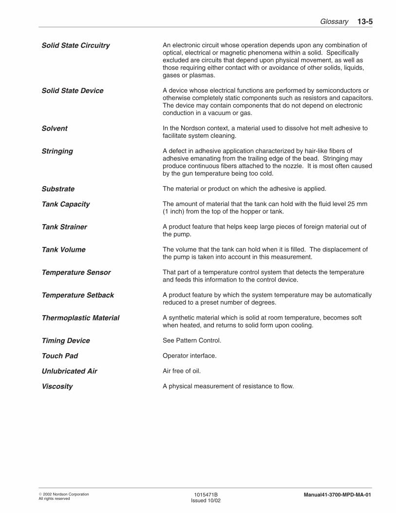
Glossary 13-5
� 2002 Nordson CorporationAll rights reserved
1015471BIssued 10/02
Manual41-3700-MPD-MA-01
An electronic circuit whose operation depends upon any combination ofoptical, electrical or magnetic phenomena within a solid. Specificallyexcluded are circuits that depend upon physical movement, as well asthose requiring either contact with or avoidance of other solids, liquids,gases or plasmas.
A device whose electrical functions are performed by semiconductors orotherwise completely static components such as resistors and capacitors.The device may contain components that do not depend on electronicconduction in a vacuum or gas.
In the Nordson context, a material used to dissolve hot melt adhesive tofacilitate system cleaning.
A defect in adhesive application characterized by hair-like fibers ofadhesive emanating from the trailing edge of the bead. Stringing mayproduce continuous fibers attached to the nozzle. It is most often causedby the gun temperature being too cold.
The material or product on which the adhesive is applied.
The amount of material that the tank can hold with the fluid level 25 mm(1 inch) from the top of the hopper or tank.
A product feature that helps keep large pieces of foreign material out ofthe pump.
The volume that the tank can hold when it is filled. The displacement ofthe pump is taken into account in this measurement.
That part of a temperature control system that detects the temperatureand feeds this information to the control device.
A product feature by which the system temperature may be automaticallyreduced to a preset number of degrees.
A synthetic material which is solid at room temperature, becomes softwhen heated, and returns to solid form upon cooling.
See Pattern Control.
Operator interface.
Air free of oil.
A physical measurement of resistance to flow.
Solid State Circuitry
Solid State Device
Solvent
Stringing
Substrate
Tank Capacity
Tank Strainer
Tank Volume
Temperature Sensor
Temperature Setback
Thermoplastic Material
Timing Device
Touch Pad
Unlubricated Air
Viscosity

Glossary13-6
� 2002 Nordson CorporationAll rights reserved
1015471BIssued 10/02
Manual41-3700-MPD-MA-01