series 6100 diaphragm actuator - honeywell process · pdf file- 1 - 1. general 1.1...
TRANSCRIPT

Revision: 1.1
Series 6100
Diaphragm Actuator
70-17-40-06-EN
INSTALLATION, OPERATION, MAINTENANCE MANUAL
Contents 1. General ....................................................................................................... 1
1.1 Introduction to Actuator ...................................................................................................... 1
1.2 Characteristics of Actuator ................................................................................................. 2
2. Storage ....................................................................................................... 2 3. Operation ................................................................................................... 3
3.1 Inspections before Operation ............................................................................................. 3
4. Maintenance and Repair ........................................................................... 4 4.1 General .................................................................................................................................. 4
4.2 Disassembly and Assembly of Actuator ............................................................................ 5
4.2.1 Disassembly (See Fig 4.1) ................................................................................................5
4.2.2 Assembly (See Fig 4.1) ....................................................................................................5
5. Preventive Maintenance and Troubleshooting ....................................... 7
5.1 Troubleshooting ................................................................................................................... 7
6. Others ........................................................................................................ 8

- 1 -
1. General
1.1 Introduction to Actuator
A) The Honeywell pneumatic diaphragm actuator has been designed to meet the requirements of
valve operation.
B) Honeywell pneumatic diaphragm actuator has been designed for easy maintenance and piping.
C) Honeywell Pneumatic Diaphragm Actuator boasts a long life span and has few faults. To use the
system to its full life span, you should install it correctly according to the manual and maintain it
according to the prescribed procedures while using it.
D) The most important feature of the Honeywell pneumatic diaphragm actuator is the size of actuators
that have been manufactured to meet the requirements of piping. The volume of the actuator was
designed to be small compared to the output torque so as to enable piping in a narrow space.
♣ RECOMMENDATIONS
Engineers who have professional assembly capabilities are required to maintain Diaphragm Actuator.
Therefore, it is more economical to request repairs of the valves to Honeywell. As the valves repaired
by Honeywell are thoroughly tested and warranted, you are recommended to entrust Honeywell with
repairs.
To avoid possible injury to personnel or damage to valve parts, WARNING
and CAUTION notes must be strictly followed. Modifying this product,
substituting non-factory parts or using maintenance procedures other than
outlined could drastically affect performance, be hazardous to personnel and
equipment and may void existing warranties.

- 2 -
1.2 Characteristics of Actuator
The Honeywell pneumatic actuator is a reversible type that allows simple switching of the valve action
on site. (See Fig 1.1); Air Fail Close ↔ Air To Open
Fig 1.1 Valve Action Switching
2. Storage
A) Do not throw, drop or drag the actuator when transporting it.
B) Keep all parts of the actuator in a well-ventilated place protected from fire, rain and wind.
Store the valve at a temperature between - 29 (℃ -20 ) ℉ and 48 (120 ).℃ ℉
The storage area must be protected from flooding.
C) Operate the elastomer (O-ring type) of pneumatic actuator at least once every six months to
prevent their functional degeneration. Operate it to the full stroke even under general operation
conditions at least three times a month.
Direct Action
Reverse Action

- 3 -
3. Operation
3.1 Inspections before Operation
A) Check whether there is any leak from all connections including the air pipe connections.
B) Check whether the attached manual hand wheel is at the Neutral position.
C) Check whether the air pressure required for valve operation is accurately set.
(Diaphragm Actuator: 4.0 kgf/cm2, Special specification: 5.0 kgf/cm2)
- WARNING -
① Remove air pressure from the actuator before using the manual hand wheel. If you use
the hand wheel without removing air pressure, it may not work normally and its weak
part may get damaged by overstrain.
② If the manual hand wheel is not at the Neutral position during control operation, it may
not work normally and its weak part may get damaged.
③ If you use a pressure higher than the specified pressure on the name plate, the rubber
and O-rings of the actuator may be damaged and cause operation problems.

- 4 -
4. Maintenance and Repair
REGULAR INSPECTION
Repair and inspect as described below. If any malfunction occurs, take appropriate measures according to
the preventive maintenance procedures and troubleshooting in Chapter 6. Also, disassemble and inspect the
system during the regular overhaul period, and replace parts if necessary.
♣ RECOMMENDATIONS
The life span of the valve can increase if you replace parts according to their replacement cycles. Refer to
the Part Replacement Cycle Sheet shown below.
Part Replacement Cycle Sheet
Item Name Replacement Cycle Others
Diaphragm Rubber 5 years
Diaphragm O-ring 3 years
IRREGULAR INSPECTIONS
① Are there abnormal noise, vibration or hunting?
② Does air pressure escape from actuator?
③ Are there any loose bolts and nuts?
4.1 General
- WARNING -
To prevent human injuries and damages to control system, close the block valve, remove
instrument air and signals from the valve and open the bypass valve to switch over the
pressure from the line to the bypass. Then slowly unfasten the bolts from the pipe until the
internal pressure of the body is completely released and remove the valve before
disassembling the driving unit.

- 5 -
4.2 Disassembly and Assembly of Actuator
GENERAL INFORMATION
For the Honeywell pneumatic diaphragm actuator, air pressure is supplied into the actuator chamber,
and the spindle moves in a straight line to activate the valve. This procedure is to adjust the valve
position to the required position by responding to control signals using air pressure.
4.2.1 Disassembly (See Fig 4.1)
① Remove actuator from the valve.
② Release the air pressure from inside the actuator and disconnect the air piping.
③ Replace 2 tension bolts and remove the others.
④ Slowly remove the remaining 2 bolts while keeping the actuator spring without load.
⑤ Remove the diaphragm cover.
⑥ Remove the back plate, and then remove the diaphragm rubber and plate from the spindle.
⑦ Visually check the O-ring and rubber for damages, and replace them if necessary.
4.2.2 Assembly (See Fig 4.1)
Assemble in the reverse sequence of the disassembly.
- WARNING -
① The components of a spring return type actuator are pressed down by a spring. Take
general safety measures and disassemble correctly. Otherwise, injuries and damages
may result.
② Remove the spindle from the plate while taking care not to damage the spindle surface.

- 6 -
Fig. 4.1 Actuator Disassembly & Assembly Diagram

- 7 -
5. Preventive Maintenance and Troubleshooting
♣ NOTE
Check and replace actuator rubber and O-ring once every 5 years depending on the frequency of use. For
other parts, replace them to prevent damages to other devices when they show a wearing sign.
5.1 Troubleshooting
Table 5.1 shows some remedies to general problems that may occur at the site while using diaphragm
actuator. For more serious problems, transport the system to the factory.
Table 5.1
Problem Solution
When actuator does
not operate
1. Check the air pressure supplied to the actuator.
2. Remove the actuator and check rubber and O-ring.
Leak from actuator
components
1. Fasten the bolts on the diaphragm frame.
2. Disassemble the actuator. Check the O-ring and rubber, and replace them
with new ones if they are damaged.
The stroke time is
delayed.
1. Check the air pressure supplied to the actuator.
2. Check the air pressure of the filter regulator.
3. Check the adjustment of accessories such as positioner and solenoid.
- 8 -
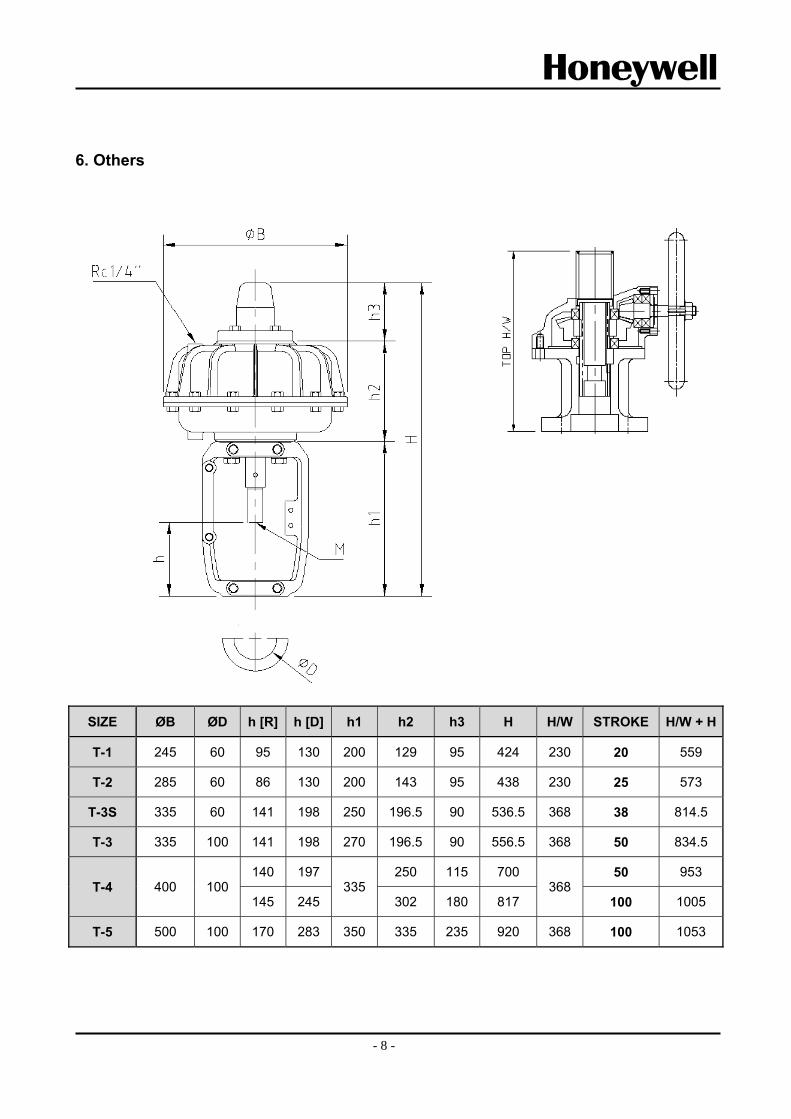
6. Others
SIZE ØB ØD h [R] h [D] h1 h2 h3 H H/W STROKE H/W + H
T-1 245 60 95 130 200 129 95 424 230 20 559
T-2 285 60 86 130 200 143 95 438 230 25 573
T-3S 335 60 141 198 250 196.5 90 536.5 368 38 814.5
T-3 335 100 141 198 270 196.5 90 556.5 368 50 834.5
T-4 400 100 140 197
335 250 115 700
368 50 953
145 245 302 180 817 100 1005
T-5 500 100 170 283 350 335 235 920 368 100 1053

- 9 -
Sales and Service
For application assistance, current specifications, pricing, or name of the nearest Authorized Distributor, contact one of the offices below. ASIA PACIFIC Honeywell Process Solutions, (TAC)[email protected] Australia Honeywell Limited Phone: +(61) 7-3846 1255 FAX: +(61) 7-3840 6481 Toll Free 1300-36-39-36 Toll Free Fax: 1300-36-04-70 China – PRC - Shanghai Honeywell China Inc. Phone: (86-21) 5257-4568 Fax: (86-21) 6237-2826 Singapore Honeywell Pte Ltd. Phone: +(65) 6580 3278 Fax: +(65) 6445-3033
South Korea Honeywell Korea Co., Ltd. Phone: +(822) 799 6114 Fax: +(822) 792 9015

For more information To learn more about Honeywell Control valves, Visit www.honeywellprocess.com Or contact your Honeywell Account Manager Process Solutions Honeywell 1250 W Sam Houston Pkwy S Houston, TX 77042 Honeywell Control Systems Ltd Honeywell House, Skimped Hill Lane Bracknell, England, RG12 1EB Shanghai City Center, 100 Jungi Road Shanghai, China 20061 www.honeywellprocess.com
70-17-40-06-EN September 2014 ⓒ2014 Honeywell International Inc.
Honeywell