series sx - file.yizimg.comfile.yizimg.com/197353/2007110804151937.pdf · please note the different...
TRANSCRIPT
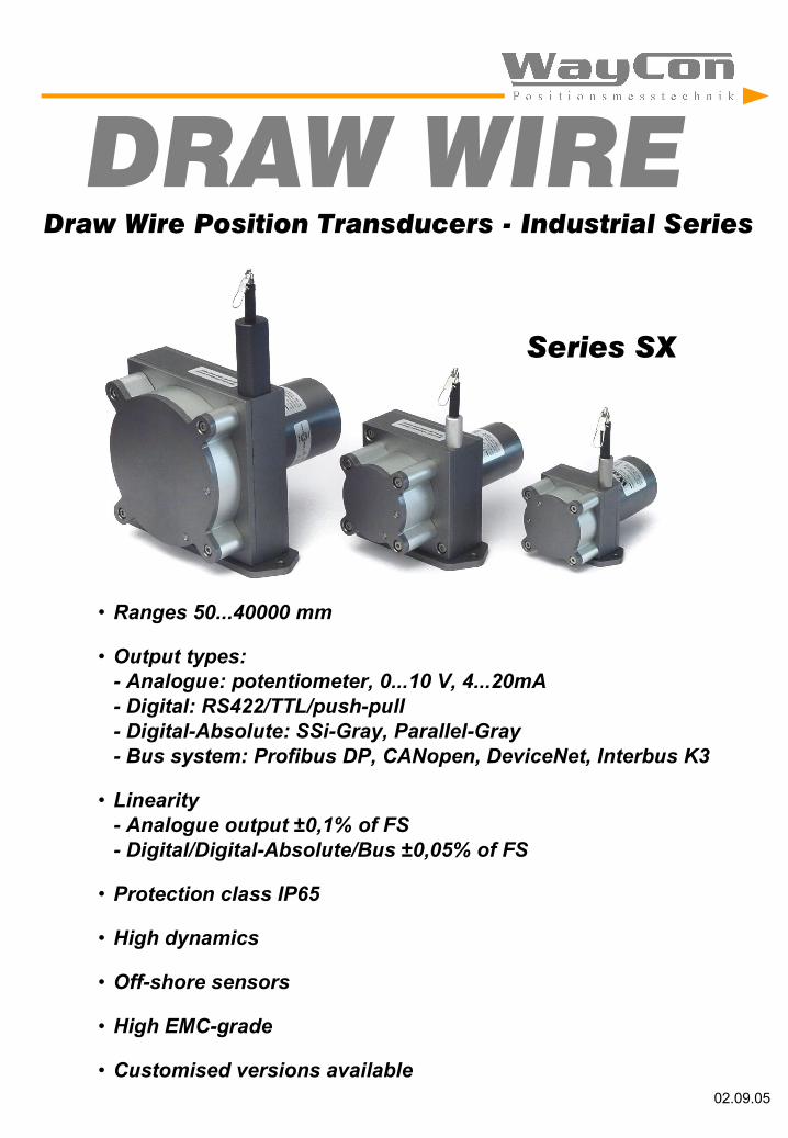
Draw Wire Position Transducers - Industrial Series
DRAW WIRE
02.09.05
Series SX
• Ranges 50...40000 mm
• Output types:- Analogue: potentiometer, 0...10 V, 4...20mA- Digital: RS422/TTL/push-pull- Digital-Absolute: SSi-Gray, Parallel-Gray- Bus system: Profibus DP, CANopen, DeviceNet, Interbus K3
• Linearity- Analogue output ±0,1% of FS- Digital/Digital-Absolute/Bus ±0,05% of FS
• Protection class IP65
• High dynamics
• Off-shore sensors
• High EMC-grade
• Customised versions available
Introduction
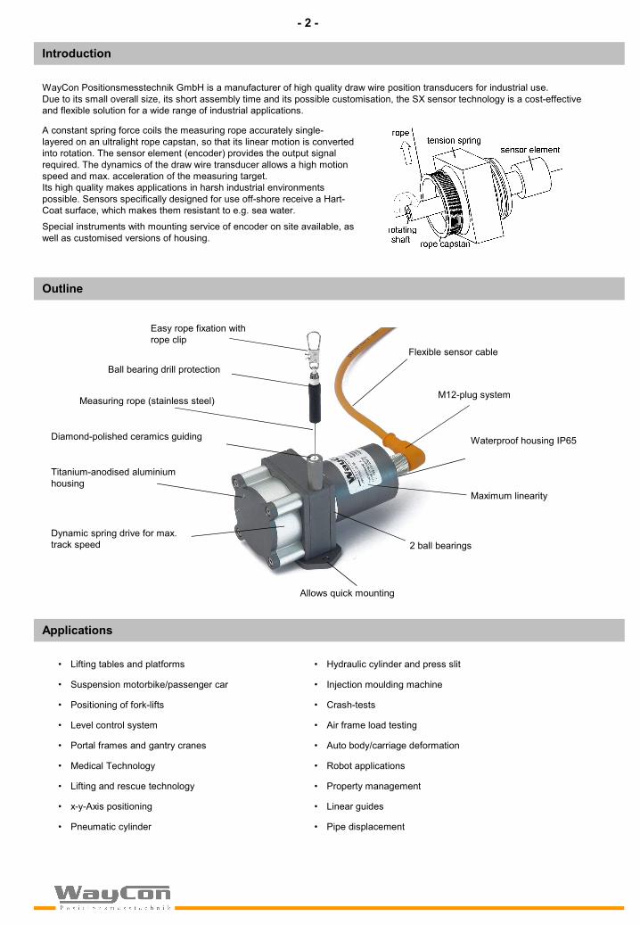
Outline
Applications
Diamond-polished ceramics guiding
Measuring rope (stainless steel)
2 ball bearings
Titanium-anodised aluminium housing
M12-plug system
Dynamic spring drive for max.track speed
Waterproof housing IP65
Maximum linearity
Allows quick mounting
• Lifting tables and platforms
• Suspension motorbike/passenger car
• Positioning of fork-lifts
• Level control system
• Portal frames and gantry cranes
• Medical Technology
• Lifting and rescue technology
• x-y-Axis positioning
• Pneumatic cylinder
• Hydraulic cylinder and press slit
• Injection moulding machine
• Crash-tests
• Air frame load testing
• Auto body/carriage deformation
• Robot applications
• Property management
• Linear guides
• Pipe displacement
Easy rope fixation with rope clip
Ball bearing drill protection
Flexible sensor cable
WayCon Positionsmesstechnik GmbH is a manufacturer of high quality draw wire position transducers for industrial use. Due to its small overall size, its short assembly time and its possible customisation, the SX sensor technology is a cost-effective and flexible solution for a wide range of industrial applications.
A constant spring force coils the measuring rope accurately single-layered on an ultralight rope capstan, so that its linear motion is converted into rotation. The sensor element (encoder) provides the output signal required. The dynamics of the draw wire transducer allows a high motion speed and max. acceleration of the measuring target. Its high quality makes applications in harsh industrial environments possible. Sensors specifically designed for use off-shore receive a Hart-Coat surface, which makes them resistant to e.g. sea water.
Special instruments with mounting service of encoder on site available, as well as customised versions of housing.
- 2 -

S1
S2
S3
standardrope outlet
standardf. cable/connector
K1
K2
Options
0 MB
10V/20mA
range
output-signal
extractretract
0V/4mA
inverted
standard
HG
A reinforced spring drive provides a greater traction outwards of the measuring rope and allows a higher max. rope acceleration. Please note the different dimensions of the housing and the higher traction of the rope. This option is available for all sensors of type series SX50.
CO
By the use of a special technology all components of the housing and of the inner mechanics of the sensor become HART-COAT ® coated. This coating is a hartanodic oxidation that protects the sensor from corrosion by aggressive media (e.g. sea water) with a hard ceramics-like layer. The sensor can thus be used off-shore.
IN
The analogue signal of the sensor is increasing with the extraction of the rope (standard). Option IN inverts the signal, i.e. the signal of the sensor declines with the extraction of the rope.
L05
Improved linearity on 0,05% of measuring range. Resolution, repeatability and sensibility remain unchanged.
IP67
Use Option IP67, if sensor is fully immersed in water (temporarily). Note that with this option there may occur a light hysteresis in the output signal due to the special sealing. The max. acceleration is reduced to 60% of the specified value.
S1/S2/S3
Optional rope outlet (see diagram) S1 rope outlet on upS2 rope outlet on down S3 rope outlet at bottom (suitable for container adjustment)
(S2/S3 with altered plate)
K1/K2
Optional cable/connector orientationfor sensors with digital output/encoder(see diagram)
M4 rope fixation
Optional rope fixation with screw thread M4. Ideal for attachment to through holes or M4-thread holes.
optionalM4 rope fixation
easy rope fixation with rope clip(standard)
- 3 -

SX50
Analogue output Digital output (Incremental)
Ranges 50/125/150/250/375/500/625/1250 mm 625/1250 mm
Output Potentiometer/0..10 V/4..20 mA (see page 12) A/B-pulse, 90° phase-delayed (see page 13)
Linearity 0,1 % (0,05%), FS 50/125: 0,5% (0,1%) 0,05%
Sensor element Hybrid potentiometer Incremental encoder
Connection M12-connector or PG-cable output M23-connector or PG-cable output
Protection class IP65
Humidity max. 90% relative, not condensating
Service life approx. 2 Mio. cycles
Weight approx. 330 g
Housing aluminium, titanium grey anodised
Mechanics - characteristics
Technical data
Resolution digital output
SX50max. 1250 mmAnalogue/Digital
*with option IP67 reduced to 60%
Z-puls-distance[mm]
1 4 8 12 16 28,8 125
Available resolution SX50[pulses/mm]
SX50 Velocity Acceleration* Acceleration*Range [mm] Fmin [N] Fmax [N] Vmax [m/s] a max [m/s²] Fmin [N] Fmax [N] a max [m/s²]
50 5,2 5,4 8 85 9,7 10,1 160125 3,8 4,0 10 100 6,4 6,7 255150 5,2 5,8 8 85 9,7 10,9 160250 5,2 6,3 8 85 9,7 11,7 160375 3,8 4,3 10 100 6,4 7,2 255500 5,2 7,3 8 85 9,7 13,7 160625 3,8 4,6 10 100 6,4 7,7 2551250 3,8 5,4 10 100 6,4 9,1 255
Rope Tension Rope Tension HG-Option
- 4 -

Technical drawings SX50
Digital output
Analogue output
Output BPotentiometer 6510V / 420A 78,5 Option S2/S3
Range Option A C50/150/250/500 mm Standard 26,5 21,6125/375/625/1250 mmStandard 33,5 10,350/150/250/500 mm HG 33,5 21,6125/375/625/1250 mm HG 46,5 10,3
Option AStandard 33,5
HG 46,5
- 5 -

SX80
Mechanics - characteristics
Technical data
Resolution Digital output
SX80max. 3000 mmAnalog/DigitalDigital-Absolut
Analogue output Digital output/Digital-Absolute/Bus systems
Ranges 1000/2000/2500/3000 mm 1000/2000/2500/3000 mm
Output Potentiometer/0..10 V/4..20 mA (see page 12) Digital -> page 13/Digital-Absolute -> page 14
Linearity 0,1 % (0,05%) 0,05%
Sensor element Hybrid potentiometer Incremental encoder/opt. Code disc
Connection M12-connector or PG-cable output M23-connector or PG-cable output
Protection class IP65
Humidity max. 90% relative, not condensating
Service life approx. 2 Mio. cycles
Weight approx. 750 g
Housing Aluminium, titanium grey anodised
*with option IP67 reduced to 60%
SX80 Velocity Acceleration*Range [mm] Fmin [N] Fmax [N] Vmax [m/s] a max [m/s²]
1000 5,4 6,6 10 1402000 5,4 7,8 10 1402500 5,4 8,5 10 1403000 5,4 9,1 10 140
Rope Tension
Z-puls-distance[mm]
0,5 2,5 5 10 25 200
Available resolution SX80[pulses/mm]
- 6 -

detailed drawing
Technical drawings SX80
Digital output
Option BCable/connector axial 54,3
Connector radial 64,3
Analogue output
Option S2/S3
Range Output Bup to 2000 mm Poti 74up to 2000 mm 10V / 420A 87,52500/3000 mm see detailed draw ing
Range Dup to 2000 mm 212500/3000 mm 35
Range Dup to 2000 mm 212500/3000 mm 35
- 7 -

SX120
Mechanics - characteristics
Technical data
Resolution digital output
SX120max. 6000 mmAnalogue/DigitalDigital-Absolute
Analogue output Digital output/Digital-Absolute/Bus systems
Ranges 3125/4000/5000/6000 mm 3125/4000/5000/6000 mm
Output Potentiometer/0..10 V/4..20 mA (see page 12) Digital -> page 13/Digital-Absolute -> page 14
Linearity 0,1 % (0,05%) 0,05%
Sensor element Hybrid potentiometer Incremental encoder/opt. Code disc
Connection M12-connector or PG-cable output M23-connector or PG-cable output
Protection class IP65
Humidity max. 90% relative, not condensating
Service life approx. 2 Mio. cycles
Weight approx. 1625 g
Housing Aluminium, titanium grey anodised
*with option IP67 reduced to 60%
SX120 Velocity Acceleration*Range [mm] Fmin [N] Fmax [N] Vmax [m/s] a max [m/s²]
3125 7,8 16,2 10 1404000 7,8 18,5 10 1405000 7,8 20,0 10 1406000 7,8 21,0 10 140
Rope Tension
Z-puls-distance[mm]
0,3 1,6 3,1 6,3 15,7 317,68
Available resolution SX120[pulses/mm]
- 8 -
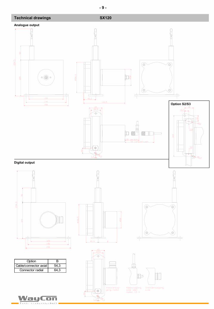
Technical drawings SX120
Digital output
Option BCable/connector axial 54,3
Connector radial 64,3
Analogue output
Option S2/S3
- 9 -

Analogue output Digital output/Digital-Absolute/Bus systems
Ranges 8/10/15/20/25/30/35/40 m 8/10/15/20/25/30/35/40 m
Output Potentiometer/0..10 V/4..20 mA (see page 12) Digital -> page 13/Digital-Absolute -> page 14
Linearity 0,1 % (0,05%) 0,05%
Sensor element Hybrid potentiometer Incremental encoder/opt. Code disc
Connection M12-connector or PG-cable output M23-connector or PG-cable output
Protection class IP65
Humidity max. 90% relative, not condensating
Service life approx. 2 Mio. cycles
Weight approx. 1625 g
Housing Aluminium, titanium grey anodised
SX135
Mechanics - characteristics
Technical data
8 m Range, digital and analogue output
SX135
*with option IP67 reduced to 60%
Resolution digital output
Z-puls-distanceRange [mm]8 m 0,28 1,4 2,8 5,6 14 357,1410 m above 0,3 1,5 3 6 15 333,33
Available resolution SX135[pulses/mm]
SX135 Velocity Acceleration*Range [m] Fmin [N] Fmax [N] Vmax [m/s] a max [m/s²]
8 7,2 16,0 10 14010/15 8,7 16,9 6 80
20 7,0 12,4 5 6025/30 7,3 15,7 5 6035/40 7,0 14,1 5 60
Rope Tension
- 10 -

Technical drawings SX135
25...40 m range, digital and analogue output
10...20 m range, digital and analogue output
Encoder (sensor element) fixed with high precision clutch and synchro plugging. Qick and easy installation.
Encoder (sensor element) fixed with high precision clutch and synchro plugging. Qick and easy installation.
- 11 -

Output
V+
V+V+signalGNDsig.GND
V+
V+V+cursorGND
A+
V+V+
signal
Analogue output
Potentiometer (voltage divider)
Output 1 kOhmSupply max. 30 VRecommended slider current <1 µANoise depending on supplyWorking temperature -20...+85°CTemperature coefficient ±0,0025 %/K
0...10V voltage output
Output 0...10 V, galvanically isolated, 4-conductorsSupply 12...30 VDCCurrent consumption max. 22,5 mA (unloaded)Output current max. 10 mA, min. load 1 kOhmDynamics < 3 ms of 0..100% and 100..0%Noise 3 mVss typisch, max. 37 mVssElectrical protection Inverse-polarity protection
Short-circuit proofWorking temperature -20...+60°CTemperature coefficient 0,0037%/K
4...20 mA current output
Output 4...20 mA, 2-LeiterSupply 12...30 VDCCurrent output max. 50 mA in case of errorDynamics < 1 ms of 0..100% and 100..0%Noise 0,03 mAss = 6 mVss at 200 OhmElectric protection Inverse-polarity protectionWorking temperature -20...+60°CTemperature coefficient 0,0079 %/K
Note: GNDsig. and GND may be connected in 3-wire system
4-pin M12 connector output(socket)Profile/view on solder side of mating connector
Cable:axial 2,0 metre standardother lengths optionalType: -, flexibleDiameter: approx. 4,5 mmCore: 0,25 mm²Temperature range: fixed in installation: -30...+80°C, flexible: -20...+80°C
pin wire color 10V 420mA 1 kOhm1 brow n V+ V+ V+2 w hite signal n.c. cursor3 blue GND signal GND4 black GNDsig. n.c. n.c.
- 12 -

Digital output
Linearity ±0,05% of FS (±0,01% of FS on request) Supply 5 VDC (line driver L) , 8...30 VDC (push-pull G)Working temp. range -25...+85°COutput Line driver RS422 (TTL-compatible), push-pull antivalent (other outputs on request)Connection 12-pin connector (radial, anticlockwise), cable output (radial, 1500 mm) Protection class encoder IP65 (IP67 on request)Max- line length Line driver RS422 up to 1000 m, push-pull up to 250 m
Power supply: 5 VDC ±5% 8 up to 30 VDCCurrent consumption without load: typ. 70 mA, max. 100 mA typ. 80 mA, max. 150 mAMax. load/canal SX50: ±10 mA ±30 mAMax. load/canal SX80/120: ±20 mA ±30 mAMax. pulse frequency SX50: 125 kHz 100 kHzMax. pulse frequency SX80/120: 300 kHz 300 kHzMin. signal level high: 2,5 V UB - 3 VMax. signal level low: 0,5 V 2,5 V
Recommended circuit:
Connection
Values for impulse and resolution in the according manuals
12pin connector output (socket)Profile/view on solder side of mating connector
Cable:radial/axial 1,5 m standardother lengths optionalType: UL2464/1061, LIYY, flexibleDiameter: approx. 6,5 mmCore: 0,25 mm²Temperature range: fixed in installation -30...+80°C,
flexible -20...+80°C
Data Electronics Line driver L Push-pull GRS 422 (TTL-compatible)
0V
+5V
A
Ā
sensor circuit
Z = 120 Ohm
Z
0V
+5V
0V
UB = 8..30 VA
Ā
sensor circuit
RL = 1 k Ohm
RL
90°
A
B
Z 90°
360°
Z-signal with A/B AND-related
Rope retracted into sensor
Output signal
Pulses A and B are 90° phase-delayed (detection of direction). The Z-signal recurs with pulse distance Z and may be used as point of reference.
Display of signal without inverted signals, timeline for return of rope.
1 9 82 10 12 73 11
546
* For line driver L only (RS422 TTL-compatible). For long line lengths it may occur that the operating voltage at the sensor does not suffice due to the output resistance. With the sensor lines 0Vsens and +UBsens the operating voltage can be checked and, if necessary, be readjusted at the input connection.
signal 0V +UB 0Vsens* +UBsens* A A- B B- Z Z- Screen12pin connector 10 12 11 2 5 6 8 1 3 4 Housing
Wire colour white brown black violet green yellow grey pink blue red Housing
- 13 -

Digital-Absolute/Bus systems SX80/SX120
Connection
Digital-Absolute output options only available for type series SX80 and SX120
Output Profibus DP CANopen DeviceNet Interbus K3 SSI-Gray Parallel-Gray
Current Consumption 250 250 250 250 100 300Connector/cable cable cable cable cable connector-12P cable-10 cm
Bus socket Bus socket Bus socket Bus socket 37-pol.3 x PG 3 x PG 3 x PG 3 x PG SUB-D
Protection class IP64Max. temp. +85°CSupply 10-30 VResolution 12 Bit Multiturn
Standard (other connection types, printouts available on request)
SSI: 12-pin socket encoder(pins anticlockwise), mating connector CON012-SParallel: 10 cm cable radial with 37-pol. SUB-D, mating connector CON037-SProfibus-DP: Bus socket: 3 x PG (middle PG N.C.)CANopen: Bus socket: 3 x PG (middle PG N.C)DeviceNet: Bus socket: 3 x PG (middle PG N.C.)Interbus-K3 Bus socket: 3 x PG (middle PG N.C.)
For wiring diagram see manual for encoder
Technical drawings (Completion of SX80/SX120)
Power
BusError
Profibus DP / CANopen / DeviceNet / Interbus K3(bus socket)
SSI-Gray Parallel-Gray
- 14 -

Deflection pulley - UR1
Using the deflection pulley the rope can be looped around to e.g. measure in places that are difficult to access or to protect the sensor from inclined traction on the rope. Ad libitum several pulleys may be used.
Material: aluminium anodisedMounting: with 2 M4 cylinder headbolts, vertical and horizontalmounting possible
Rope extension - SV
For bridging a greater distance from the measuring target to the sensor a rope extension can be applied. The rope clip (drill protection) must not be guided over the deflection pulley.
Please specify the length needed in your order
Magnet clamp - MGG1
Use the magnetic clamp to quickly attach the rope to metal objects without any assembly time. A rubber coating provides sparing contact (e.g. on varnished surfaces) and prevents from slipping due to vibration. Magnet with Neodym core for an increased adhesive force of 260N. Possibility of attaching a drill protection (rope clip).
Digital distance and speed measurement - PAX
Use PAX to visualise the covered distance or the speed (Tacho sensor) of the position transducer. It enables a transmission of the measurement data on the computer via interface. The comparator allows a Good-Bad-evaluation (limiting values function).
Inputs: Incremental/Analogue, 2 independent counter, 1 Tacho sensor2 or 4 limiting values (plug in card)Analogue output (0)4...20 mA, 0...10 V (plug in card)Serial interfaces: RS 485, RS232, DeviceNet (plug in card)Protection class (front panel) IP 656-digit display and power supply 11...36 VDC or 85...250 VAC
For further information please ask for the data sheet for the PAX display series.
Cable with M12 mating connector straight and angular - K4P(for analogue output Poti/10V/420A)
Cable with straight connector:K4P2M-S-M12 2 mK4P5M-S-M12 5 mK4P10M-S-M12 10 m
M12 mating connector straight and angular for analogue output - CON4P (zur Eigenkonfektion)
Straight connector: CON4P-S-M12 Angular connector: CON4P-SW-M12
Protection class: IP67Temperature: -25...+90°CConnection: Screw clampsCable aperture: ø3...6,5 mmCable cross-sectional area: max. 0,75 mm²Good chemical and oil resistance
Cable with angular connector:K4P2M-SW-M12 2 mK4P5M-SW-M12 5 mK4P10M-SW-M12 10 m
M23 mating connector for Digital output and SSI - CON012-S
M23, straight12 pin connector clockwise(fits in anticlockwise encoder sockets)Metal housing
Accessories
- 15 -

Installation
Warning notices
• Mount the sensor at the designated place at the fixing holes before extracting the rope and before attaching the rope to the measuring target.
• Open the rope clip (not with set screw M4) after the sensor is fully mounted and extractthe measuring rope. Hook the rope clip on the measuring object and close the bracket of the clip. For your safety put a screw driver trough the clip to extract the rope.
• Check the track of the measuring target on collision with the sensor housing and on exceeding the specified measurement range. When installing the sensor make sure that the rubber stopper does not touch the rope outlet.
• Connect the electronics according to the sensor type. When laying the cables be careful not to under-run the min. allowed bending radius of the cable (5x cable diameter).
• The rope must be extracted from the sensor vertically. The max. variation from the vertical is 3°. Avoid carefully extracting the rope at an inclination, since the durability of the instrument would shorten considerably.
• The measuring range / the zero point begins after approx. 2 mm extracted rope. The mechanical reserve at the end of the measuring range is approx. 20 mm.
• When mounting outdoors protect the sensor and the rope from ice-formation for negative temperatures.
• Lay the rope preferably in corners or guarded in guidings to prevent pollution or accidental touch.
• When operating the sensor, take care not to let the rope snap back by mistake or extract the rope over the specified measurement range, as this might destroy the sensor.
• Maintenance: These instruments are maintenance-free. If however, the rope is soiled due to adverse environmental conditions, it should be cleaned with a cloth drenched in resin-free machine oil.
• Don‘t let the rope snap back. If the rope is retracted freely, this may lead to injuries (whiplash effect) and the instrument may be damaged. Caution when unhooking and retracting the rope into the sensor.
• Never exceed the specified measurement range when extracting the rope!
• Don‘t try to open the instrument. The stored energy of the mainspring may lead to injuries when being mishandled.
• Don‘t touch the rope when operating the sensor.
• Avoid guiding the rope over edges or corners. Use a deflection pulley instead.
• Don‘t operate the sensor if the rope is buckled or damaged. A ripping of the rope may lead to injuries or damaging the sensor.
- 16 -

TypesSX50SX80SX120SX135
5080120135
SX
Optional rangesSX50:50/125/150/250/375/500/625/1250SX80: 1000/2000/2500/3000 mmSX120: 3125/4000/5000/6000 mmSX135: 8/10/15/20/25/30/35/40 m**
z.B.1250z.B.2000z.B.6000z.B.40
Analogue outputPotentiometer 1 k OhmVoltage output 0...10VCurrent output 4...20mA
1R10V
420A
OptionsIncreased acceleration SX50
HART-COAT coatingInverted output
Improved linearity 0,05%Waterproof IP67Rope outlet up*
Rope outlet down*Rope outlet bottom*
M4 Rope fixation
HGCOIN
L05IP67S1S2S3M4
ConnectionM12 connection axial
Cable output axialSAKA
Order code analogue output
TypesSX50SX80SX120SX135
5080120135
SX
Output type (Digital output only)Line driver RS422
Push-pull antivalentLG
Optional ranges SX50: 500/1250SX80: 1000/2000/2500/3000 mmSX120: 3125/4000/5000/6000 mmSX135: 8/10/15/20/25/30/35/40 m**
z.B.1250z.B.2000z.B.6000z.B.40
Digital output pulses/mmSX50: 1/4/8/12/16/28,8SX80: 0,5/2,5/5/10/25SX120: 0,3/1,6/3,1/6,3/15,7SX135 (8 m): 0,28/1,4/2,8/5,6/14SX135 (10 m above): 0,3/1,5/3/6/15
z.B.8z.B.5
z.B.6,3z.B.14z.B.15
OptionsIncreased acceleration SX50
HART-COAT coatingRope outlet up*
Rope outlet down*Rope outlet bottom*
Cable/connector orientation upCable/connector orientation left
M4 Rope fixation
HGCOS1S2S3K1K2M4
ConnectionConnector output radial (not SX50)
Cable output axialCable output radial
SRKAKR
Order code digital output/Digital-Absolute/Bus systems
Digital-Absolute/Bus systemsSSI-GrayParallel-GrayProfibus DPCANopenDeviceNetInterbus K3
SSIPARPROCANDVNINT
Office KölnAlte Fischenicherstr. 4650997 KölnTel. +49 (0)2232 96 58 03Fax +49 (0)2232 96 58 05
Head OfficeInselkammerstr. 882008 UnterhachingTel. +49 (0)89 61 20 84 70Fax +49 (0)89 61 20 84 83
WayCon Positionsmesstechnik GmbHe-mail: [email protected]: www.waycon.de
We reserve the right to alter the specification without prior notice.
*not for SX135**SX135 Range in m
*not for SX135**SX135 Range in m
- 17 -