server manual
TRANSCRIPT

Network Proximity Access Control System
701 Server
User Manual
Ver. 6.20
2
Table of Contents Page
1. Introduction ------------------------------------------- 2 Brief introduction of 701 Server and 701 Client ------------------------------------------- 2
1.1 Menu Bar content ------------------------------------------- 2 1.2 Tool Bar content ------------------------------------------- 2
2. Installation ------------------------------------------- 3 3. Operator Management ------------------------------------------- 5 4. Access Level ------------------------------------------- 5 5. LAN Base & Communication Port Setting ------------------------------------------- 6
5.1 How to be on-line between PC and controllers ------------------------------------------- 6 5.2 Communication port setting via com port or TCP/IP ------------------------------------- 8 5.3 Communication port setting via Modem ------------------------------------------- 9 5.4 Communication port setting via Server Computer ------------------------------------------- 10
6. Lan Chart -------------------------------------------- 12 7. 701E / 716E PARAMETER ------------------------------------------- 12
7.1 Program on-line reader location ------------------------------------------- 12 7.2 How to enter 701E / 716E parameter setting ------------------------------------------- 13 7.3 On-line Reader ------------------------------------------- 13 7.4 Door Number ------------------------------------------- 16 7.5 Duress Code & Force On/Off Code ------------------------------------------- 17 7.6 Reader Relay vs. 701E Relays ------------------------------------------- 17 7.7 Time-scheduled Output -------------------------------------------- 18 7.8 DI Input vs. Relay Output Connection ------------------------------------------- 19 7.9 Parking Space ------------------------------------------- 20
8. ACC-950FP Parameter Setting ------------------------------------------- 21 8.1 Program ACC-950FP single-door networking controller location ------------------- 21 8.2 How to enter ACC-950FP parameter setting ------------------------------------------- 21 8.3 How to assign Door Number ------------------------------------------- 21 8.4 How to change Node ID by software ------------------------------------------- 22 8.5 How to change master code by software ------------------------------------------- 22 8.6 Time schedule for Door Relay, Wait Delay (Door Close Tm), Alarm Delay, Alarm Relay 22 8.7 How to change standby mode’s title on the LCD display ------------------- 23 8.8 Duress Code ------------------------------------------- 23 8.9 Daily Time Schedule ------------------------------------------- 23 8.10 Other function ------------------------------------------- 24
9. Time Attendance ------------------------------------------ - 27 10. Message Import ------------------------------------------ - 28 11. Change the picture that enter 701 Server ------------------------------------------ - 30

3
12. Remarks columns ------------------------------------------ - 31 ACC-1000V2 System Setting Table ------------------------------------------- 31 ACC-950FP System Setting Table -------------------------------------------- 31
1. Introduction 1.1 Brief introduction of 701 Server and 701 Client 701 Server and 701 Client are multiple language and true 32-bit software package that runs under Windows 98, 2000, NT and XP, and is for all Eclipse Proximity Access Control off-line networking systems. The 701 Server is a dedicated software program that provides with mainly communication port selection, data collection, system components physical connection, and all the controller’s parameter settings. With the TCP/IP remote access ability, this feature can support remote location configuration and data collection. Through the NetBEUI protocol and Local Area Network, the Server Computer and Client Computers can be spread throughout many offices and buildings; authorized users can monitor the system by using either Server Computer or Client Computer in their offices. The 701 Client is a software program that dedicates the software tools for Door Access Control, Time & Attendance, Payroll, Elevator Control, Car Park Control, Access Records Reports, Time & Attendance Daily/Monthly Reports, Projects Management and Operators Authority Level Control. System also provides with the ability to import bitmap files for photos. 1.2 Menu Bar content
1.3 Tool Bar content

4
2. Installation Install the 701 Server: Before installing the Server, make sure both the reader and the controller are
well set, the controller is also connected to the computer via a converter (RS485→RS232). Insert the
CD-to-CD ROM. Step 1: Run file [ 701ServerSetup.exe ] for the following windows:
Step 2: Follow the on-screen instructions to click [ NEXT ] until [ Setup Finished ] to be Shown on windows. Step 3:Click [ Finish ] to complete the installation.
5
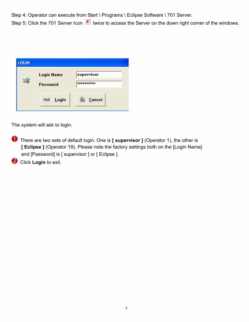
Step 4: Operator can execute from Start \ Programs \ Eclipse Software \ 701 Server. Step 5: Click the 701 Server Icon twice to access the Server on the down right corner of the windows.
The system will ask to login.
There are two sets of default login. One is [ supervisor ] (Operator 1), the other is [ Eclipse ] (Operator 19). Please note the factory settings both on the [Login Name] and [Password] is [ supervisor ] or [ Eclipse ].
Click Login to exit.

6
3. Operator Management
After initialing login with the factory settings (the highest level), users can reset their own favorite [Login Name] and [Password]. The Steps are as follows:
Choose Password under the Help menu item, then as shown below. Select operator number. Select a favorite [ Login Name ] and [ Password ]. Select Access Level. (See Also: Access Level under the Help menu item) Click [Yes] to complete NEW settings.
The [ Login Name ] and [ Password ] consist of any combination of up to 18 characters or 9 Chinese characters. Access Level means a limitation of authority to access the 701 Server, the range is from 0 ~ 63. Access Level 63 is then highest management. Rank access levels from high to low in order of numerals, and 0 is the lowest access levels. The system can support up to 20 Operators that the highest management is also included.
4. Access Level The system provides operators with different access levels ranged from 0 to 63 to manage the software. Click Toolbar Icon for the following Dialog Box:
An operator with a proper access level is always recommended (63 is the highest level). NOTE: Only the operator with access level 63 can login to add/delete/ modify other operators. Operator with access level lower than 63 can login to modify only its own Login Name and Password.

7
5. LAN Base & Communication Port Setting The system can communicate with networking controller through COM. Port, Modem, TCP / IP or Via Server PC. 5.1 How to be on-line between PC and controllers? After the hardware connect ok, please follow below step.
Step1: Click Toolbar Icon to set up LAN Base.
Server computer needs to know the type and the Node ID of controllers of the framework (LAN base).
Select [ LAN BASE ] to ACC1000/950FP. Select the Node ID that will be assigned to the controller. The computer can connect up to 255 sets of
controllers. Click the [Show Range] drop down list to select the Node ID range. Click controller Node ID and select controller type from the drop down list. Press [ Yes ].
• How to be on-line between PC and controllers? Presupposition: controllers and on-line readers connect ok, and Node ID is set ok. • How to set networking controllers and on-line reader’s Node ID?
Remark: Please refer to hardware user’s manual. Hereby brief explanation: (1) Networking controller has two series, ACC-1000 and ACC-950FP series.
Acc-1000 Node ID is set by DIPswitch, and ACC-950FP is set by keypad. (2) On-line reader’s Node ID is set by keypad.

8
Note: (1) When ACC1000 series and 950FP series networking controller are used at the same
time, 950FP series must be set Master Node. (Setting on the ACC-1000/ACC-950FP Parameter Setting) (2) When communication type via TCP/IP, we must click IP and enter IP address and TCP/IP port. Two
condition: Condition 1: If head office and subsidiary company is in same LAN, IP Address can be fictitious. Condition 2: If head office and subsidiary company is not in same LAN, IP Address of Subsidiary company must be virtual and fixed so that head office monitors its remote subsidiaries with an expanding TCP/IP. Note: IP Address is a site address that applied from the local telephone office.
(3) 727H CPU Version 4.2 – mode 9 directly connect to PC through AR-801CM converter for only Time and Attendance function.
Can connect to PC through AR-801CM for only Time and Attendance function. (Version 4.2 UP)
◎ Under Mode 9, keep 480 transactions
◎ 1000 user cards capacity.
◎ Not support Anti-pass-back, lift control, Time zone and Door group.
◎ Please note transaction record just show normal access Message, without the message from invalid card and Push button.
◎ It can be used together with ACC-1000 series, 950FP networking controller through parallel installation.
Step2: After completed setting LAN Base, click Toolbar Icon selecting communication port:

9
5.2 Communication port setting via com port or TCP/IP
Check if the cable is well connected, and select Communication Port. There are two communication ports COM: 1 and COM: 2 in the computer. For Com: 3, Com:4, Com:5, Com:6 and TCP / IP, it will be available only after added with expanding accessories.
Click [ Polling Message From Controller ]. Select suitable [ Polling Interval ] to poll the messages from controller (recommended to set to
200ms). Press [ Yes ] and to save all the settings, the on the right down corner of the windows will flash that
indicates in normal communication. The color of Server Icon indicates the status of communication. (1) Red means TRANSMITTING. (2) GREEN means RECEIVING. (3) WHITE means IDLING. (4) BROWN means COMMUNICATION ERROR.
Note: 1. If system configuration has via COM port and Ethernet at the same time, communication port must
select COM port.
10
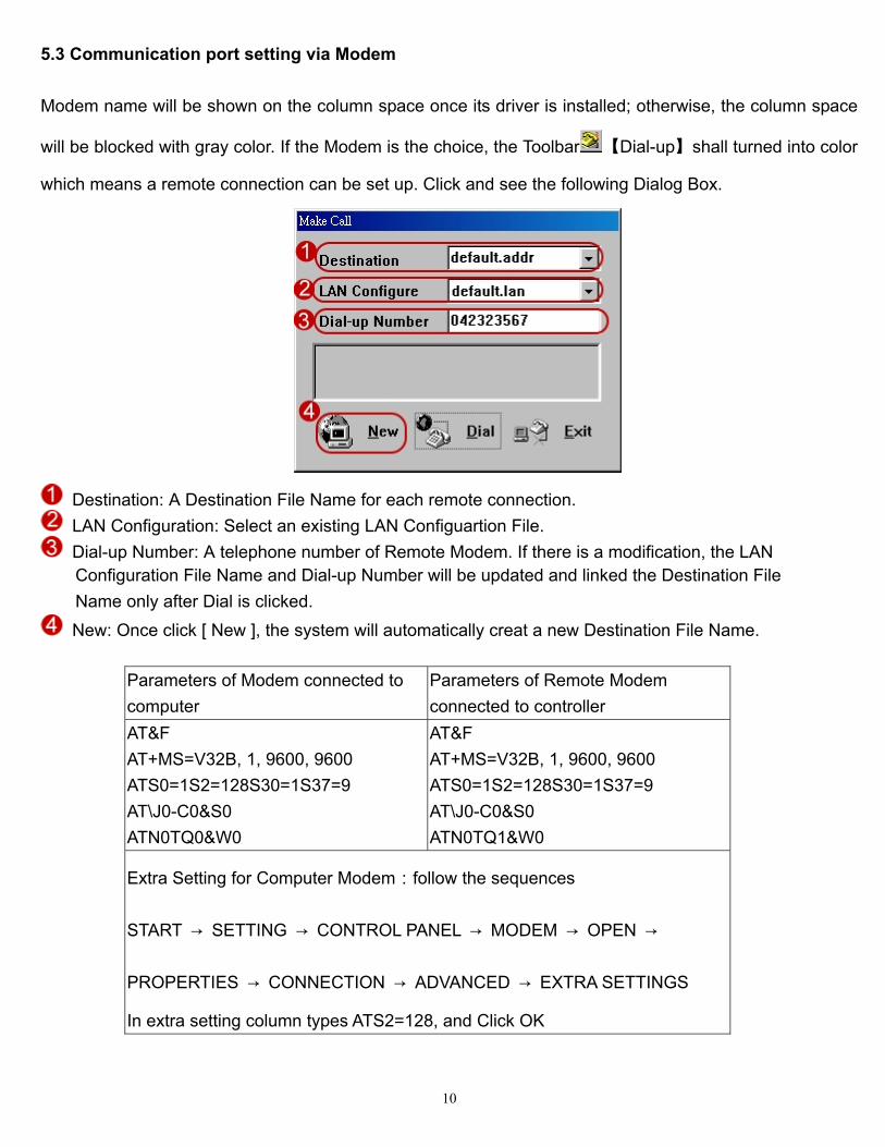
5.3 Communication port setting via Modem Modem name will be shown on the column space once its driver is installed; otherwise, the column space
will be blocked with gray color. If the Modem is the choice, the Toolbar 【Dial-up】shall turned into color
which means a remote connection can be set up. Click and see the following Dialog Box.
Destination: A Destination File Name for each remote connection. LAN Configuration: Select an existing LAN Configuartion File. Dial-up Number: A telephone number of Remote Modem. If there is a modification, the LAN
Configuration File Name and Dial-up Number will be updated and linked the Destination File Name only after Dial is clicked.
New: Once click [ New ], the system will automatically creat a new Destination File Name.
Parameters of Modem connected to computer
Parameters of Remote Modem connected to controller
AT&F AT+MS=V32B, 1, 9600, 9600 ATS0=1S2=128S30=1S37=9 AT\J0-C0&S0 ATN0TQ0&W0
AT&F AT+MS=V32B, 1, 9600, 9600 ATS0=1S2=128S30=1S37=9 AT\J0-C0&S0 ATN0TQ1&W0
Extra Setting for Computer Modem:follow the sequences
START → SETTING → CONTROL PANEL → MODEM → OPEN →
PROPERTIES → CONNECTION → ADVANCED → EXTRA SETTINGS
In extra setting column types ATS2=128, and Click OK

11
5.4 Communication port setting via Server Computer The Server Computer shall select the [ Via Server Computer ] communicate with controller. Click Server Path to choose the path to Server Computer. Assign [ Server Path ] to Server Computer via Network Neighborhood. Note: 1. We name the computer that connect to ACC-1000V2 Server Computer, and name other computer
Client Computer via Network Neighborhood. 2. Server Computer and Client Computer install both 701 Client and 701 Server software. 3.
a. Communication port of Server Computer selects COM port or TCP/IP and click [ Polling Message From Controller ].
b. Communication port of Client Computer selects “via server Computer” and direct to server path and don’t click [ Polling Message From Controller ].

12
Step 1: Please share Server Computer’s path C:\program files\ 701 Server and C:\program files\ 701 Client to Client Computer. (Sharing setting depends on operating system; therefore, we don’t explain how to sharing hereby)
Step 2: Client PC’s communication port setting
Click [ Via Server Computer ]. Direct to server path. Don’t click [ Polling Message From Controller ]. Click [ Yes].
Step 3: Be sure that Server PC and Client PC support “NetBEUI” protocol. Step 4: Client Computer’s project files management setting
Direct to Server Computer’s project files management path Click [ Save ].
Step 5: Close 701 Client windows and execute 701 Client again.

13

14
6. Lan Chart
Check the ON/OFF line status of the system devices; click Toolbar for the following tree structure:
As indicated, the system has one set of ACC-1000 controller (Node ID 001) and two sets of ACC-950FP controllers (Node ID 002 and 003). (1) White [ ? ] means devices ON or OFF not stable. (2) Blue [ Y ] means devices ON line. (3) Red [ X ] means devices OFF line. Click Exit to exit this sub-menu.
7. 701E / 716E Parameter 7.1 Program on-line reader location Program on-line reader location, and assign on-line reader Node ID, door number & parameter setting. Step:1 Press * and master code follow an # Step:2
Enter 0 0 * 0 0 1 #
Range 001~254. Default setting: NNN= 001 Step:3 Press * #
Before on-line reader installation, fill up the “ACC-1000 & ACC-950FP System Setting Table” for the record. NOTE: See ACC-1000 / ACC-950 user’s guide for more information.

15
7.2 How to enter 701E / 716E parameter setting How does the Server receive the Data information from the controller and the reader?
Click Tool Bar Icon (701E / 716E parameter) for the windows:
*Note the 701E/716E the programmer for the ACC-900 and ACC950
Select controller number Click [ Read ].
Click [ Read ] for only one controller; otherwise, fill up the Controller Number that designated, for example 001 & 002 indicates Controller 1 & Controller 2; then click [ Read ].
7.3 On-line Reader
Present select controller number. There are two Channels, Channel 1 & Channel 2, on the controller, each Channel can connect up
to 8 readers. From above, for example, there are two readers connected to Channel 1 with

16
Reader 001 & Reader 002, then click [ 001 ] & [ 002 ]. Remember to click [ Master Controller ] to prevent the system from On-line communicating badly,
especially for more than one controller in the system. Press [ Write ].
The features on the right column are: (1) Clear Messages: Clear all messages in ACC-1000V2 or ACC-950FP controller. (2) Master Controller: Choose this item if it is a Master. There must be only one master controller for all the controllers in the system. It is for using com port diagram. If it is for using Ethernet diagram, you must click this item for all controller in the system. (3) K3 Anti-passback Err/K4 Alarm: Once this item is chose, violate anti-pass back feature will
activate K3 Relay, and for each alarm relay of the reader that connected to this controller is activated will also activate the K4 Relay. The K3/K4 Relays activated time based the time setting (000 ~ 250 seconds) on sub-menu [ DI INPUT V.S. RELAY OUTPUT ].
(4) Reassign Time Zone: Once this item is chose, the system can provide single controller with entry/exit different doors, different Time Zones features; however, the Time Zones in Setting “User Card Edit” will be reduced from 64 to 16 Time Zones.
Time Zone and Door Number will automatically divided into the following 4 sections.
Time Zone 01-15 17-31 33-47 49 -63 Door Number 01-63 64-127 128-191 192-255
For example, There are three control door groups as Main Gate & Front Door, Office& R&D Department, Production Line & Warehouse Department. Time Zone Control Personnel Senior Officer Staff Operator Main Gate & Front Door No No No Office & R&D Department No 8:00AM - 19:00PM No Production Line & Warehouse Department
No 8:00AM - 18:00PM. 8:00AM - 17:00PM
The steps as follows: Step 1. Assign “Door Number” in the 701 Server\701E / 716E parameter setting \ Door Number. Door Name Main Gate Front Door Office R&D Dept. Production Line Warehouse Dept. Door No. 001 002 064 065 128 129 Step 2: Define “Time Zone” in the 701 Client\ Time Zone.

17
Time Zone 01 17 33 02 18 34 Time 00:00AM -
23:59PM 08:00AM - 19:00PM
08:00AM - 18:00PM
00:00AM - 23:59PM
00:00AM - 23:59PM
08:00AM - 17:00PM.
Staff time zone for 01, 17 and 33; and Operator time zone for 02, 18 and 34. Step 3: Enter “Time Zone in the 701 Client\ User Card Edit. User Senior Officer Staff Operator Time zone NO 01 02
(5) Enable Auto Open (Zone: 63): Once this item is chose, the specified reader(s) will be in LATCH-OFF mode based on the time periods specified on the Time Zone 63 and other linked Time Zones if any. Additionally, each Specified Readers has to be set to enable Auto Open feature using Command 20 from 721H’s keypad and command 32 from 727H’s keypad. Note: Once the Auto Open Timing is beginning, the door relay of this reader will be in LATCH-OFF mode after the first access. The door relay will automatically activate at the end of this time period. a. Define Time Zone in 701 Client\ Time Zone: Maintain Time Zone 063 as Auto Open Timing. b. Assign Additional Function from reader keypad.
◎ AR-721H
Step 1: Press * and master code fallow an # enter programming mode
Step 2: Enter 2 0 * N N N # NNN: default value 016 (NNN = default value + 4)
Step 3: Press * # to exit programming mode.
◎ AR-727H
Step 1: Press * + 1 2 3 4 5 6 + # enter the “FUNCTION MENU” Step 2: Enter command 32 to start Auto open zone function. Step 3: Return to main menu and enter command 6 to exit FUNCTION MENU.
(6) Enable Auto Disarming (Zone: 62): Once this item is chose, the specified reader(s) will be automatically in Disarming or Arming based on the time periods specified on the Time Zone 62 and other linked Time Zones if any. Note: Once the Auto Disarming Timing is beginning, the readers will be in Disarming mode until end of the time period to become Arming mode. Additionally, each Specified Readers has to be set to enable Remote Control Function feature using Command 20 from 721H’s keypad and command 32 from 727H’s keypad. The steps as the above “Enable Auto Open (Zone: 63)”.
(7) Reader LCD Show (Day/Month): Once this item is chose, the date format will be switch from

18
MM/DD/Hour/minute/second. (8) DI 1 to Active Release All Doors: Release all the emergency exits if there is a fire event. This
function can be used to release the specified readers (doors) while in an emergency until after making an access normally. Additionally, each specified reader(s) has to be set to enable Door Release Button from its reader keypad.
(9) Auto Reset Anti-pass (Zone 61): Once this item is chose, the anti-pass-back will automatically reset and restart. This means to disregard present entry/exit door status of card user and resume the anti-pass-back feature. The momentary reset time is specified on the Time Zone 61.
(10) On K2 While Reader Off Line: Once this item is chose, and the k2 relay connect to alarm device. When on-line reader which connect to controller is off-line with the controller, K2 will be active alarm.

19
7.4 Door Number Assign a Door Number (1 – 255) to each reader. In 701 Client software, user can assign a Door Name for each Door Number. Please note the meanings of Reader Node ID and Door Number are different. Door Number means number that assigned to each door, but Reader Node ID means number that assigned to controller and reader. The Door Number can be repeated. For example, there are two sets of ACC-1000V2 controllers together with one set of ACC-950FP controller in the Framework, and each ACC-1000V2 controller connect 2 readers. Assign Reader Node ID “001” & “002” to ACC-1000V2 respectively, then Reader Node ID “003” to ACC-950FP reader. In fact, the factory setting of ACC-950FP is 001. Remember the reader Node ID 003 has been assigned and it will not be able to use to assign to other readers any more; otherwise, an abnormal communicating status will be occurred. Setting Reader Number by Command 00. Press 0 0 * N N N # (NNN means Reader Node ID.)
Input reader door number 1. Reader 1-8 is the door number of the CH1 RS-485 readers.
(The CH1 can connect to on-line reader Node ID 1-8). 2. Reader 9-16 is the door number of the CH2 RS-485 readers.
(The CH2 can connect to on-line reader Node ID 9-16). Note: The above Door number can be both changeable.
1. Node ID of WG reader port 1 is fixed to no.17 on the ACC-10002/Ei PCB. If enable anti-pass-back, Node ID 17 is fixed to be in door.
2. Node ID of WG reader port 2 is fixed to no.18 on the ACC-10002/Ei PCB. If enable anti-pass-back, Node ID 18 is fixed to be out door.
Note: The above Door number can be both changeable. Press [ Write ].

20
7.5 Duress Code & Force On / Off Code
User can assign up to 4 Force On/Off Codes for all the readers that connected to this controller.
These codes can be used to on/off the relays on the controller After card access successfully, input 4 Force On/Off Codes, Relay Number, and F1 to activate (F2 to deactivate) a specified ACC-10002/Ei Controller Relay.
User can assign up to 4 Duress Codes for all the readers that connected to this controller. Instead of user Card Code, input Duress Codes on reader panel for access, computer will instruct to open door, at the same time a message will be sent for help.
Press [ Write ]. 7.6 Reader Relay vs 701E Relays
Select reader number User can assign up to 20 relays ( But ACC-1000V2/Ei just has four sets of relays for K1, K2, K3 and
K4 ) on the controller to synchronize with the Door Relay of each reader. Instead of using the outdoor use Reader Door Relay, user can use Controller Relay to open the door that can increase the safety of the system.

21
Press [ Write ].

22
7.7 Time-Scheduled Output The controller (ACC-1000 Series) can support 4 different bells, for example, company factory Regular TIME IN/TIME OUT bells, Lunch TIME IN/TIME OUT bells. From the Relays K1 ~ K4 on the controller, up to 12 designated Time-scheduled Outputs can be set per day, 7 days a week. 000 means no activated time. The activated time of relays ranges from 001 ~ 250 seconds. As indicated below:
Select “Weekday” The “Ranges” can assign 12 designated Time-scheduled Outputs. Time zone 1 to Time zone 6 are on
the first page, select from the drop down list for Time zone over 6. From the Relays K1 ~ K4 on the controller, can connect up to 4 different bells. Allow differently the time of trigger bells. From the activated time of relays, can adjust time of bells. Press [ write ]
ACC-1000 Controller, Relay Output & DI Input

23
7.8 DI Input V.S. Relay Output Connection
The controller has 4 DI inputs, it can activate the controller relays or readers Door Relays that are selected.
If DI input connected to the reader, once the DI input is activated, the reader Door Relays are activated for a period of time (Door Opening Setting on the reader itself.) If DI input connected to Relays 00 ~ 15 (this function is just suitable for AR-701E) , once the DI input is activated, the relays on the controller that assigned to the DI inputs are also activated synchronously. If DI input connected to Relays K1 ~ K4, once the DI input is activated, the Relays K1 ~ K4 are activated for times that are based on the time setting (001 ~255 seconds) of this menu. As settings, the DI 1 is activated, the controller Relay K1 is activated for 5 seconds. If the time setting is 000, then the relay is in LATCH-ON/LATCH-OFF toggle mode, and the situation will be changed until DI input being activated next time. DI-0: It can be NO Momentary (Sink) or Voltage (Source, 12VDC) input, and can be selected by ON/OFF switch inside of the controller. 1. The DI.2 is exit button input of WG reader port 1 and the K1 is open door relay.
(1) Choose “DI 2” under the menu item.
(2) Click “K1”.
2. The DI.3 is exit button input of WG reader port 2 and the K2 is open door relay. (1) Choose “DI 3” under the menu item.
(2) Click “K2”.
Note: Active second can be set only when the window is DI 1. Once the cardholder accesses the door successfully, the controller relays are activated for a certain
period of time based on the time setting as above, for example, 5 seconds. The setting time is 001 – 255 seconds. 000 for LATCH-ON (this function is just suitable for AR-701E).
Press [ Write ].

24
7.9 Parking Space
The controller provides parking spaces with All Full or All Empty monitoring functions, assign any one of the 20 controller relays for its All Full or All Empty indication respectively.
Before initiating use, enter total car spaces, total car inside parking lots. And assign All Full & All Empty activated output relays.
However, the function is only applied to the initiating use anti-passback user cards to entry/exit anti-passback control door.

25
8. ACC-950FP Parameter Setting 8.1 Program ACC-950FP single-door networking controller location Assign ACC-950FP ID, door number & parameter setting by software and keypad.
Set Node ID by keypad shown bellow: Step 1: Press * + 1 2 3 4 5 6 + # enter the “FUNCTION MENU” Step 2: Enter command 31 to edit Node ID. Step 3: Return to main menu and enter command 6 to exit FUNCTION MENU. 8.2 How to enter ACC-950FP parameter setting
Click [ Read From Controller ] Then show factory default.
8.3 How to assign Door Number? Step 1: Enter Door Number in the “Door Num.” position. Default value is 1, so we suggest that please
Before AR-829E/821EF installation, fill up the “ACC-950FP System Setting Table” for the record. NOTE: See ACC-950FP user’s guide for more information.

26
assign door number same with Node ID to avoid message is error from controller read in the future. Step 2: Click [ Write To Controller ]. 8.4 How to change Node ID by software? Step 1: Enter new Node ID in the “Node Adr.” position. Step 2: Click [ Write To Controller ]. 8.5 How to change master code by software? Step 1: Enter new 6-digit master code in the “Master” position. Step 2: Click [ Write To Controller ]. 8.6 Time schedule for Door Relay, Wait Delay (Door Close Tm), Alarm Delay, Alarm Relay Timing 1 Sequence-
After arming is set, the system enters TTiimmiinngg 11 SSeeqquueennccee. Right on CChheecckk PPooiinntt AA, the system is in arming situation and enters Arming Mode. If door is close, the system engages the Timing 2 Sequences. If abnormal condition arisen, will cause Alarm, e.g. Door open too long (over allowed time), Force open, violating anti-pass-back regulation Timing 2 Sequences-
Flashing card OK
Arming Delay TimeTiming 1
Check Point AArming is set
Signal OutputArming
Signal OutputArming
If TTT = 000Level Triggle
ArmingSignal Output
If TTT = 200Pulse Trigger
Pulse TriggerIf TTT = 050
0.5 Second
2.0 Seconds
Sequence
Door Relay Wait Delay Alarm Delay Alarm Relay Timing 2 Sequences

27
Arm. Pass: User presses 1 2 3 4 # after access the door, then the unit will toggle the
arming/disarming mode. Default value: 1234 (4-digits).

28
8.7 How to change standby mode’s title on the LCD display? Step 1: Click [ Idle Screen ]. Step 2: There are two rows can be written on the LCD display. Then click [ OK ] to exit.
Step 3: Click [ Write To Controller ]. 8.8 Duress Code User can assign up to 4 sets of Duress Codes for ACC-950FP. Instead of user Card Code, input Duress Codes on the keypad for access, computer will instruct to open door, at the same time a message will be sent for help. 8.9 Daily Time Schedule The ACC-950FP controller can support one set of bell, for example, company factory Regular On Duty, Off Duty, Break Out, and Break In bell. From Alarm Relay on the controller, up to 12 designated Time-scheduled Outputs can be set per day, 7 days a week. 000 means no activated time. The activated time of relays ranges from 001 ~ 250 seconds. As indicated below:
Select “Weekday”. Allow differently the time of trigger bells.
From the activated time of relays, can adjust time of bells. Click [ Yes ].
Note that if time attendance depends on function key of the Controller, this function supports auto-run duty as the right table. For example, enter 8:00 in the On Duty position and enter 12:00 In the Break Out position, when it is 8:00 O’clock on Monday, It will show Duty:0 on the LCD display of the device, until 12:00 O’clock, LCD display will change to BRK:0 status. It is convenient that user don’t select duty via function key before flashing card in the status when time attendance depends on function key.

29
8.10 Other function
(1) Empty Controller Messages: Clear all messages on ACC-950FP controller. (2) Master Node: Choose this item if it is a Master. There must be only one master controller for all the controllers in the system. It is for using com port diagram. If it is for using Ethernet diagram, you must click this item for all controller in the system. (3) English Menu: Choose this item, LCD display will be shown in English. (4) Date Format (DD/MM): Once this item is chose, the date format will be switch from
MM/DD/Hour/minute/second. (5) Enable Force Alarm: Once this item is chose, when door is open via forced open action in the
disarming mode, alarm relay will be triggered active. (6) Enable Egress Button: Once this item is chose, user can access the door via press push button. (7) Enable Auto Relock: Once this item is chose, door sensor feels the door status is close, it will auto
re-lock. (8) Auto Open (Zone: 63): Once this item is chose, the ACC-950FP will be in LATCH-OFF mode based
on the time periods specified on the Time Zone 63 and other linked Time Zones if any. Note: Once the Auto Open Timing is beginning, the door relay of this reader will be in LATCH-OFF mode after the first access. The door relay will automatically activate at the end of this time period.
(9) Auto Disarm (Zone: 62): Once this item is chose, the ACC-950FP will be automatically in Disarming or Arming based on the time periods specified on the Time Zone 62 and other linked Time Zones if any. Note: Once the Auto Disarming Timing is beginning, the readers will be in Disarming mode until end of the time period to become Arming mode.
(10) Reset Anti-pass (Zone 61): Once this item is chose, the anti-pass-back will automatically reset and restart. This means to disregard present entry/exit door status of card user and resume the anti-pass-back feature. The momentary reset time is specified on the Time Zone 61.
(11) Check Fingerprint: Once this item is chose, user can access the door via flash card + fingerprint or 4-digit user address + F4 function key + fingerprint.
(12) Is Time Attendance: Once this item is chose, event transactions on the controller will put into time attendance report. Ex. Daily Time and Attendance Report and Multi-day Time and Attendance Report.
(13) Auto Duty Functions: Once this item is chose, LCD display of the controller will show duty on the above right corner.
(14) Stop Alarm While Door Closed: Once this item is chose. User can be disarming by door closed,

30
when alarm relay is triggered. (15) Enable Anti-pass-back: Once this item is chose. The ACC-950FP and one set of wiegand reader
will have anti-pass-back function for each other. Note that card also needs to enable anti-pass-back function by 701 client \ user card edit.
(16) Separate Door Relay: Once this item is chose, WG reader that connects to ACC-950FP can control separate door. Note that this function cannot use with arming function at the same time. Station field will add t ‘Exit’ to distinguish transaction record between ACC-950FP and its slave reader in Daily Transaction Record. Therefore, please notice the following message.
(17) Enable via Master: There are 5 user cards, started from user address 0000 to 0004, to enable or
disable “ Door Access ” function. The feature is used for those companies that need someone in particular to enable or disable reader with “ Door Access ” function everyday. The person must be on duty in the earliest and off duty at the latest. The employees can access door to work after this function has been generated; when disabled, the employees cannot access door anymore. Controller operating method: After flashing card, pressing F1 function key within 2 seconds, will enable or disable the function. [ Enable ] Reader – It only can enable under the access mode by flashing card. [ Disable ] Reader – It can enable both under the access mode by flashing card or pressing
5-digit user address + 4-digit user Code.

31
Note that be sure to press F1 function key after flashing card, otherwise, there will only be as general transaction records.
Such as below illustration:
Note that there will only be enable / disable reader records on the Daily Transaction Record.
(18) Max Error Times: Keypad will be locked for 30 seconds, while continuous “N” times error operation for PIN Code & Master Code. Default: 3 times, N: 0-9, if you don’t want this function, you can enter “0” to cancel this function.
(19) Msg. Overflow: The storage of messages of controller ACC-950FP for 17,000 records are 1,1000 records. While the PC is on OFF-line status, the numbers of present messages will be shown on controller LED display. For example, the ACC-950FP is off-line with PC, it can store 17,000- transactions within its memory chip and upload those transactions (Datas) automatically to the PC when ever the PC link is established, this way the reader creates new space for recording new transactions. If, its memory is full, the latest ones will replace old transaction. It means it is not necessary that the PC must be "ON" always to keep records of every transaction. The [ Msg. Overflow ] feature is used to remind user open the PC to poll messages by the device sounds beep after user flash card every time when message storage is high than the presenting numbers (if it is set 10,000). If you don’t want this function, you can enter “0” to cancel this function.
(20) On Alarm for Expiry: Once this item is chose. When someone flashes overdue card on the device, alarm relay will be triggered.
(21) Open Door via P.I.N. Selection: It is good for the access mode of Card or PIN. Usually, if you select card or PIN access mode, user can access the door by just either flash card or entering 5-digit user address + 4-digit PIN + # for Serial Num + PIN Only selection. If you click this selection for PIN Only, user can access the door by just either flash card or directly
entering 4-digit PIN. (22) External Reader Format: ACC-950FP can be external one set of auxiliary reader for
WG26/34 format (Default) or ABA10 format. (23) TP1 Serial Port Format: Universal serial port supported for LED display, printer, lift controller, etc. (24) Upload Fingerprint Data: We can deliver every fingerprint from one controller to the pc
depending on this function. Please refer to ACC-950FP user’s guide for detailed explanation. (25) Download Fingerprint Data: We can download every fingerprint to another controller. Upload /
download fingerprint Data Function are used to save time when we edit many controllers. Please refer to ACC-950FP user’s guide for detailed explanation.
(26) Empty Fingerprint Data: Delete all fingerprint database on ACC-950FP. Please refer to ACC-950FP user’s guide for detailed explanation.

32
9. Time Attendance Choose Time Attendance under the Setting menu item, then as shown right:
There are two types of Time & Attendance that selected in the Time Attendance. Please select
either one for your Time & Attendance type. (1) First and Last Record: The system will treat the first record (first record after 4:00AM) and last
record (last record before 4:00AM next day) of the day as employee TIME-IN and TIME-OUT respectively.
(2) Depend on Function: There is Function Keys on the reader and can set Regular Hours TIME-IN/TIME-OUT, Temporary TIME-IN/TIME-OUT by just press the right Function Keys for Time & Attendance Records.
The software doesn’t support 3 shifts, however, it provides with overnight function. Click Maximum User On System depends on your requirement.
Don’t change any more once choose it. Mark [ Download clock to reader while program start ! ]. Press [ ok ]
Other function: (1) Duty Start Time: The on-duty time will be treated as same day if the TIME-OUT is over 24:00PM
and before 03:59AM next day. (2) Backup Message File To Second Path: Usually, we put daily message into the default path
C:\Program Files\701 Server if user doesn’t change the path when installs software. This function is used to daily message also be backup to another path in the same time. How to do? Just click it and direct the path which you want to backup.
(3) Call the Process while Startup: If you want to execute 701 Server, wake up another program (ex. 701 Client) in the same time. Just click it and direct the path that you want to wake up program.

33
10. Message Import It is good for some companies locate its branch office that installs proximity reader in the suburbs that there is no Ethernet area. We can take notebook to receive daily message to here in regular time. Because parent company also installs proximity reader, it will also generate daily message every day in the path C:\Program Files\701 Server. Daily message file of branch office (hereinafter referred to as B) cover daily message file of parent office (hereinafter referred to as A) in order to avoid import message. We need to open one folder for “B” in advance in the “A” path C:\Program Files\701 Server For example, we put “B” 20021001.msg, 20021002.msg and 20021003.msg to the folder named branch office. Then we import these messages one by one via Message Import under the Setting menu item. The steps as follows:
Click “Branch office folder”. Click the message that would like to import one by one. Click “Open ”, then message is import immediately to the file 20021001.msg of parent company to
combine one file.
The difference between before import and after import shown as follows:

34

35
12. Remarks columns
ACC-1000V2 System Setting Table Controller Node ID: Master:
Node ID 1 2 3 4 5 6 7 8 9 10 11 12 13 14 15 16 Door No.
On-line Readers
Door Name Controller Node ID: Master:
Node ID 1 2 3 4 5 6 7 8 9 10 11 12 13 14 15 16 Door No.
On-line Readers
Door Name Controller Node ID: Master:
Node ID 1 2 3 4 5 6 7 8 9 10 11 12 13 14 15 16 Door No.
On-line Readers
Door Name Controller Node ID: Master:
Node ID 1 2 3 4 5 6 7 8 9 10 11 12 13 14 15 16 Door No.
On-line Readers
Door Name Controller Node ID: Master:
Node ID 1 2 3 4 5 6 7 8 9 10 11 12 13 14 15 16 Door No.
On-line Readers
Door Name Controller Node ID: Master:
Node ID 1 2 3 4 5 6 7 8 9 10 11 12 13 14 15 16 Door No.
On-line Readers
Door Name Controller Node ID: Master:
Node ID 1 2 3 4 5 6 7 8 9 10 11 12 13 14 15 16 Door No.
On-line Readers
Door Name
ACC-950FP/ 821EF System Setting Table Node ID Master Door No. Door Name Node ID Master Door No. Door Name Node ID Master Door No. Door Name