service maintenance manual - morgan olson
TRANSCRIPT

1801 S. Nottawa StreetSturgis, MI 49091
Phone 800-233-4823Fax (616-659-0499)
www.morganolson.comwww.morganolsonparts.com
UNITED STATES POSTAL SERVICE2- TON DELIVERY TRUCK
SERVICE MAINTENANCE MANUAL
P/N 43004536

2 Genuine OEM Parts 1.800.233.4823 www.morganolsonparts.com
CO
NFI
DEN
TIAL
NO
T FO
R D
ISTR
IBU
TIO
N
C
ON
FID
ENTI
AL N
OT
FOR
DIS
TRIB
UTI
ON
NOTE: USE ONLY GENUINE MORGAN OLSON PARTSUSE OF NON OEM PARTS MAY VOID YOUR WARRANTY
AND/OR VIOLATE FMVSS STANDARDS
INTRODUCTION
This catalog has been prepared to assist the U.S.P.S. In the maintenance of the Morgan Olson 2-Ton delivery truck. Inquiries on items found or not found in this manual may be made through the address and or phone numbers listed below.
Morgan Olson1801 S. NottawaSturgis, MI 490911-800-477-8287
(Customer Service/Fleet Warranty)
For Parts Ordering:1-800-233-4823
1-616-659-0499 (Fax)(Service Parts)
Latest version of all documents available at;https://www.morganolsonparts.com/parts-catalogs/usps

3USPS 2 Ton Delivery Vehicle 2016 - 2018 Models
CO
NFID
ENTIAL N
OT FO
R D
ISTRIBU
TION
CO
NFID
ENTIAL N
OT FO
R D
ISTRIBU
TION
ContentsCONTENTS & INTRODUCTION 2-3
1. BODY TIE/DOWNS 42. DOORS
Side Doors 5-9 Bulkhead Door 10 Rear Door 11-17
3. GAS SPRING 184. HEATER
Motor, Fan & Plenum 19 Troubleshooting 20-31
5. HOOD 326. LAMPS 337. BODY PANEL REPLACEMENT AND RIVETS 348. WINDSHIELD
Windshield Removal and Installation 359. WINDSHIELD WIPERS & MOTOR 3610. LIFT-GATE 37-6111. BACK-UP CAMERA & MONITOR 62-7012. REAR VIEW MIRROR SYSTEMS 71-7813. KEY-LESS ENTRY SYSTEM 79-8414. VEHICLE JACKING POINTS 8515. MAINTENANCE SCHEDULE (CHASSIS) 86-9516. ELECTRICAL WIRING DIAGRAMS 96-115

4 Genuine OEM Parts 1.800.233.4823 www.morganolsonparts.com
CO
NFI
DEN
TIAL
NO
T FO
R D
ISTR
IBU
TIO
N
C
ON
FID
ENTI
AL N
OT
FOR
DIS
TRIB
UTI
ON Body Tie/Downs
Tie/Down Check:
The floor of the truck is fastened to bolsters that extend the length of the floor. The lower flanges of the bolsters are mounted to the chassis frame rails. Both sets of fasteners are torqued to specifications. All cab and body tie/downs should be checked after 3 months and annually.
5USPS 2 Ton Delivery Vehicle 2016 - 2018 Models
CO
NFID
ENTIAL N
OT FO
R D
ISTRIBU
TION
CO
NFID
ENTIAL N
OT FO
R D
ISTRIBU
TION
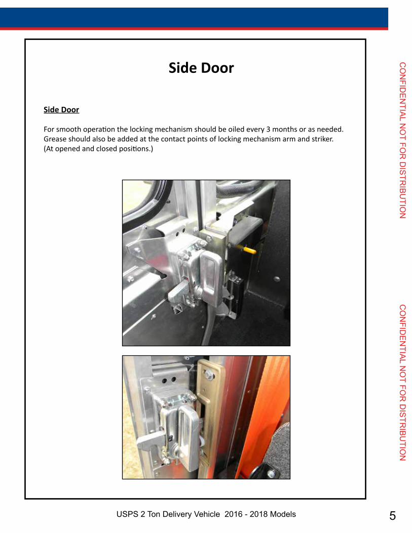
Side Door
Side Door
For smooth operation the locking mechanism should be oiled every 3 months or as needed.Grease should also be added at the contact points of locking mechanism arm and striker. (At opened and closed positions.)

6 Genuine OEM Parts 1.800.233.4823 www.morganolsonparts.com
CO
NFI
DEN
TIAL
NO
T FO
R D
ISTR
IBU
TIO
N
C
ON
FID
ENTI
AL N
OT
FOR
DIS
TRIB
UTI
ON Side Door Removal:
1. Remove screws fastening down the lower door track but leave the track in position.
2. Remove the Phillips screws and door pocket cover plate located in the upper rear corner of the door pocket.
3. Remove the 4 fasteners and the door handles (inner and outer).
4. Using a socket wrench, remove the bolts fastening the door and hanger assembly.
5. To simplify door removal, remove the grab handle located forward of the door. *Fold side view mirror back.
6. Holding the top of the door in position, pull out on the bottom front corner of the door until it clears the body of the truck. Then tilt the top of the door down and out and re-move the door.
Weather Seal Removal:1. The forward and rear weather seals are installed simply by sliding into a mated part. To
remove simply pull straight out from the top of the door or door frame. Install by feeding into the mated part and sliding into place.
Handle Mechanism Removal:1. To remove the door handles simply remove the 4 mounting screws. Pay special attention
to spacer locations. You can then remove the inside and outside handles. Remember when installing the handles, position of the spacers identical to the way they were at removal.
Door Track (Upper) Removal:1. The upper track is mounted to the header channel. Remove the nuts, and the track. Rein-
stall by reversing the removal sequence.
Wear Strip (Lower) Removal:1. Remove side door.2. Remove existing rivets.3. Replace wear strip and rivet in place.
7USPS 2 Ton Delivery Vehicle 2016 - 2018 Models
CO
NFID
ENTIAL N
OT FO
R D
ISTRIBU
TION
CO
NFID
ENTIAL N
OT FO
R D
ISTRIBU
TION
Side Door Installation:1. Tilt the top of the door in place first. Now position the bottom of the door into the lower
door track, which is in position but not fastened down.
2. Put 1/8” shims between the lower door track and the wear strip.
3. Mount door to the hanger assembly.
4. Install door handles. See page 8.
5. Mount cover plate on upper rear door pocket.
6. Mount grab handle forward of door. *Re-adjust mirror.
7. For proper door adjustment see page 10.
8 Genuine OEM Parts 1.800.233.4823 www.morganolsonparts.com
CO
NFI
DEN
TIAL
NO
T FO
R D
ISTR
IBU
TIO
N
C
ON
FID
ENTI
AL N
OT
FOR
DIS
TRIB
UTI
ON Side Door Adjustment:
1. Loosen all nuts on the top of the slotted upper door track.
2. Loosen the 3 screws fastening down the lower door track.
3. The rear holes of the lower door track are oversized to allow for adjustment. Only the rear portion of the track can be adjusted. The forward hole of the lower track is not oversized because the door must retain its forward position to ensure proper alignment when the door is closed.
4. With the door closed and engaged in the forward strike, adjust the upper track for uni-form lateral placement of the door in the forward post seal. Snug the forward bolt of the upper door track.
5. With the door open and engaged in the rear strike, the rear portion of the upper and low-er tracks can be adjusted laterally to ensure proper alignment with the rear striker.
6. When the door is positioned, tighten a few of the fasteners in the upper and lower tracks. Operate the sliding door to ensure that it slides and latches properly.
7. When the door is operating properly, tighten all the remaining fasteners in the upper and lower door tracks.
8. Replace any broken studs with .25 - 20x1.00 truss head screw.
9 See figure 1 on the following page.
Door Latch Adjustment:1. The door latches (strikers) and the mounting brackets provide for adjustment in a variety
of directions.
2. Once the door has been adjusted to slide smoothly, then adjust the strikers for proper latch operation.

9USPS 2 Ton Delivery Vehicle 2016 - 2018 Models
CO
NFID
ENTIAL N
OT FO
R D
ISTRIBU
TION
CO
NFID
ENTIAL N
OT FO
R D
ISTRIBU
TION

10 Genuine OEM Parts 1.800.233.4823 www.morganolsonparts.com
CO
NFI
DEN
TIAL
NO
T FO
R D
ISTR
IBU
TIO
N
C
ON
FID
ENTI
AL N
OT
FOR
DIS
TRIB
UTI
ON
Bulkhead Door:*NOTE: Where grease is required use a lithium based.
1. The latch should be greased to prevent sticking. Grease should be applied at contact points of the latch and striker for smooth operation. This should be done every 3 months.
Bulkhead Door

11USPS 2 Ton Delivery Vehicle 2016 - 2018 Models
CO
NFID
ENTIAL N
OT FO
R D
ISTRIBU
TION
CO
NFID
ENTIAL N
OT FO
R D
ISTRIBU
TION
Rear Roll-Up Door:1. Apply oil to the roller shafts and locking mechanism every 6 months.
2. Perform a visual inspection daily checking the lifting mechanism cables and the door strap for fraying.
3. Perform a visual inspection monthly checking for damaged parts replace immediately to prevent wear and fatigue on other components.
4. Refer to Trans global Door Company instructions for proper rear door spring adjustment and/or replacement.
Rear Door
12 Genuine OEM Parts 1.800.233.4823 www.morganolsonparts.com
CO
NFI
DEN
TIAL
NO
T FO
R D
ISTR
IBU
TIO
N
C
ON
FID
ENTI
AL N
OT
FOR
DIS
TRIB
UTI
ON
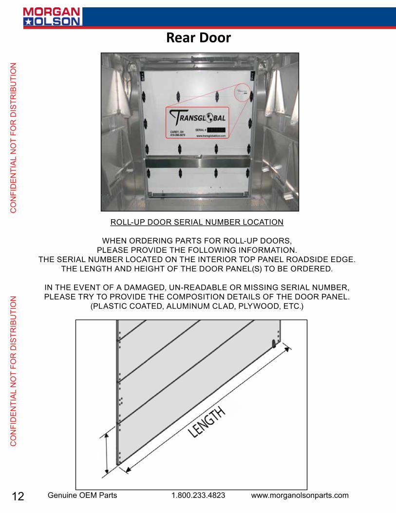
RoLL-uP dooR seRiaL NumbeR LocatioN
WheN oRdeRiNg PaRts foR RoLL-uP dooRs, PLease PRovide the foLLoWiNg iNfoRmatioN.
the seRiaL NumbeR Located oN the iNteRioR toP PaNeL Roadside edge. the LeNgth aNd height of the dooR PaNeL(s) to be oRdeRed.
iN the eveNt of a damaged, uN-ReadabLe oR missiNg seRiaL NumbeR, PLease tRy to PRovide the comPositioN detaiLs of the dooR PaNeL.
(PLastic coated, aLumiNum cLad, PLyWood, etc.)
Rear Door

13USPS 2 Ton Delivery Vehicle 2016 - 2018 Models
CO
NFID
ENTIAL N
OT FO
R D
ISTRIBU
TION
CO
NFID
ENTIAL N
OT FO
R D
ISTRIBU
TION
ITEM# PART# DESCRIPTION1 47106737 beaRiNg assembLy2 47106738 side seaL sNaP-iN styLe 75.5” 3 47106739 1” head PRotectoR yeLLoW4 47106740 Lock catch5 47106741 Latch guaRd aNgLe - Lh (cs)6 47106742 Latch guaRd aNgLe - Rh (Rs)7 47106743 5/16” x 1” hex head boLt gRade 58 47106744 5/16 keP Nut9 47106745 1/4 -20 x 1 3/4” hex head boLt (25c175hcs5Z)
10 47106746 1/4” keP Nut11 47106747 veRticaL tRack assembLy - #47106270- cuRbside12 47106748 veRticaL tRack assembLy - #47106270- Roadside13 47106749 hoRiZoNtaL tRack assembLy- #47106270- cuRbside14 47106750 hoRiZoNtaL tRack assembLy- #47106271- Roadside
Counterbalance Assembly 15 47106751 couNteRbaLaNce assembLy - #4710627016 47106752 5/16” x 1” hex head boLt gRade 517 47106753 cabLe dRum Lh 18 47106754 cabLe dRum Rh 19 47106755 couNteRbaLaNce shaft - 68.75”21 47106737 beaRiNg assembLy
17
5
10
4
6
211
87
1
13
9
310
14
122
4
10
16
182119
15
3
ROLL UP DOOR

14 Genuine OEM Parts 1.800.233.4823 www.morganolsonparts.com
CO
NFI
DEN
TIAL
NO
T FO
R D
ISTR
IBU
TIO
N
C
ON
FID
ENTI
AL N
OT
FOR
DIS
TRIB
UTI
ON
ROLL UP DOOR
1118
6
13
5
8
12
1018
3
417
16
15
15
14
11
9
8
2
8
2
7
15USPS 2 Ton Delivery Vehicle 2016 - 2018 Models
CO
NFID
ENTIAL N
OT FO
R D
ISTRIBU
TION
CO
NFID
ENTIAL N
OT FO
R D
ISTRIBU
TION
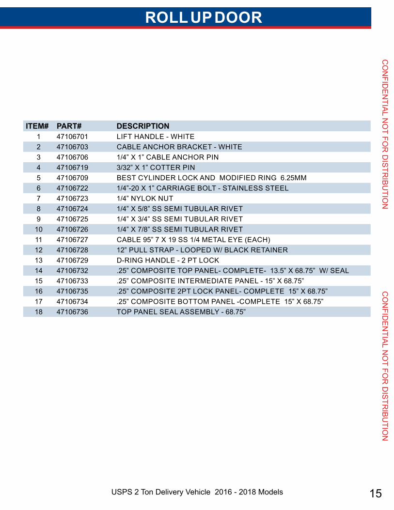
ROLL UP DOOR
ITEM# PART# DESCRIPTION1 47106701 Lift haNdLe - White2 47106703 cabLe aNchoR bRacket - White3 47106706 1/4” x 1” cabLe aNchoR PiN4 47106719 3/32” x 1” cotteR PiN5 47106709 best cyLiNdeR Lock aNd modified RiNg 6.25mm6 47106722 1/4”-20 x 1” caRRiage boLt - staiNLess steeL7 47106723 1/4” NyLok Nut8 47106724 1/4” x 5/8” ss semi tubuLaR Rivet9 47106725 1/4” x 3/4” ss semi tubuLaR Rivet
10 47106726 1/4” x 7/8” ss semi tubuLaR Rivet11 47106727 cabLe 95” 7 x 19 ss 1/4 metaL eye (each)12 47106728 12” PuLL stRaP - LooPed W/ bLack RetaiNeR13 47106729 d-RiNg haNdLe - 2 Pt Lock14 47106732 .25” comPosite toP PaNeL- comPLete- 13.5” x 68.75” W/ seaL15 47106733 .25” comPosite iNteRmediate PaNeL - 15” x 68.75”16 47106735 .25” comPosite 2Pt Lock PaNeL- comPLete 15” x 68.75”17 47106734 .25” comPosite bottom PaNeL -comPLete 15” x 68.75”18 47106736 toP PaNeL seaL assembLy - 68.75”

16 Genuine OEM Parts 1.800.233.4823 www.morganolsonparts.com
CO
NFI
DEN
TIAL
NO
T FO
R D
ISTR
IBU
TIO
N
C
ON
FID
ENTI
AL N
OT
FOR
DIS
TRIB
UTI
ON
ROLL UP DOOR
6
9
10
17
119
3
4
20
2
14
13
5
18
87
13
1615
11
17USPS 2 Ton Delivery Vehicle 2016 - 2018 Models
CO
NFID
ENTIAL N
OT FO
R D
ISTRIBU
TION
CO
NFID
ENTIAL N
OT FO
R D
ISTRIBU
TION
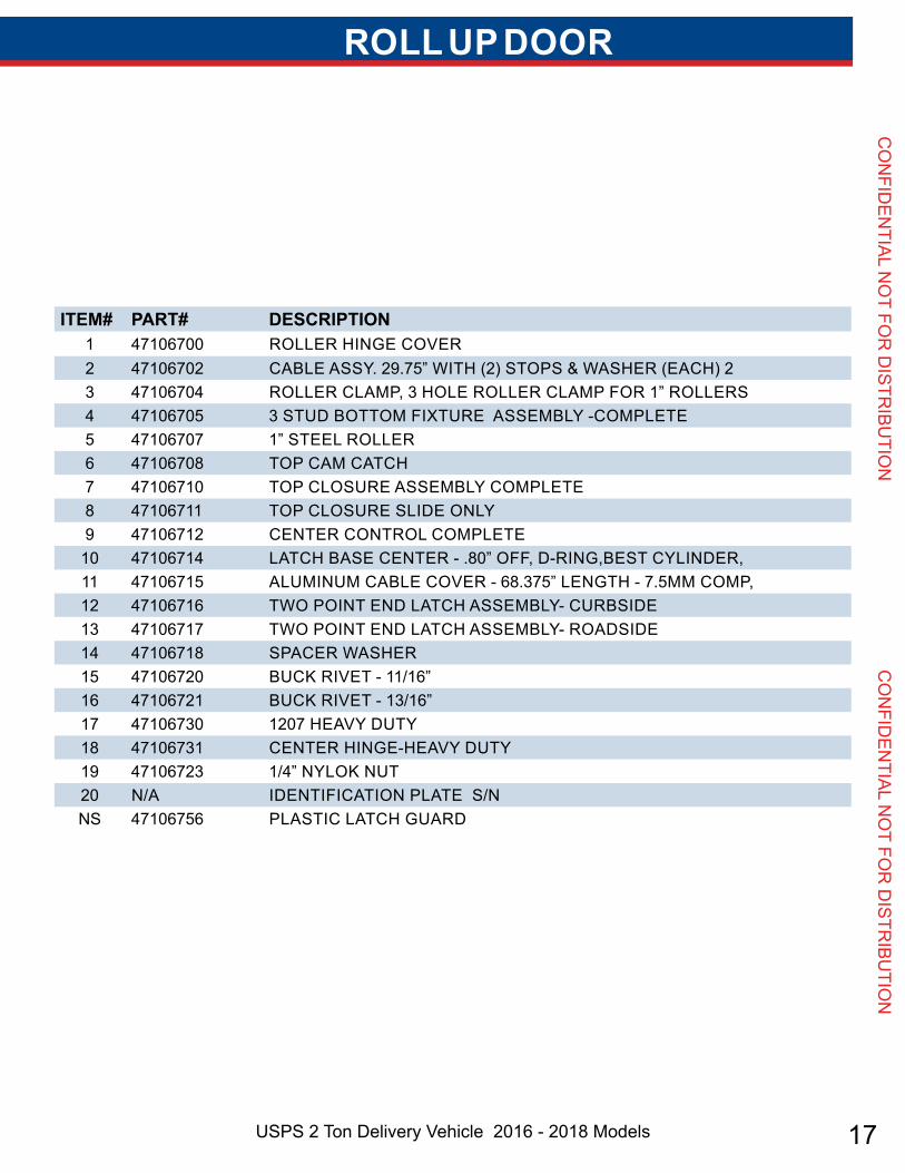
ITEM# PART# DESCRIPTION1 47106700 RoLLeR hiNge coveR2 47106702 cabLe assy. 29.75” With (2) stoPs & WasheR (each) 23 47106704 RoLLeR cLamP, 3 hoLe RoLLeR cLamP foR 1” RoLLeRs4 47106705 3 stud bottom fixtuRe assembLy -comPLete5 47106707 1” steeL RoLLeR6 47106708 toP cam catch7 47106710 toP cLosuRe assembLy comPLete8 47106711 toP cLosuRe sLide oNLy9 47106712 ceNteR coNtRoL comPLete10 47106714 Latch base ceNteR - .80” off, d-RiNg,best cyLiNdeR,11 47106715 aLumiNum cabLe coveR - 68.375” LeNgth - 7.5mm comP,12 47106716 tWo PoiNt eNd Latch assembLy- cuRbside13 47106717 tWo PoiNt eNd Latch assembLy- Roadside14 47106718 sPaceR WasheR15 47106720 buck Rivet - 11/16”16 47106721 buck Rivet - 13/16”17 47106730 1207 heavy duty18 47106731 ceNteR hiNge-heavy duty19 47106723 1/4” NyLok Nut20 N/a ideNtificatioN PLate s/NNs 47106756 PLastic Latch guaRd
ROLL UP DOOR
18 Genuine OEM Parts 1.800.233.4823 www.morganolsonparts.com
CO
NFI
DEN
TIAL
NO
T FO
R D
ISTR
IBU
TIO
N
C
ON
FID
ENTI
AL N
OT
FOR
DIS
TRIB
UTI
ON
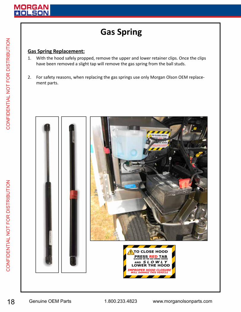
Gas Spring Replacement:1. With the hood safely propped, remove the upper and lower retainer clips. Once the clips
have been removed a slight tap will remove the gas spring from the ball studs.
2. For safety reasons, when replacing the gas springs use only Morgan Olson OEM replace-ment parts.
Gas Spring
19USPS 2 Ton Delivery Vehicle 2016 - 2018 Models
CO
NFID
ENTIAL N
OT FO
R D
ISTRIBU
TION
CO
NFID
ENTIAL N
OT FO
R D
ISTRIBU
TION
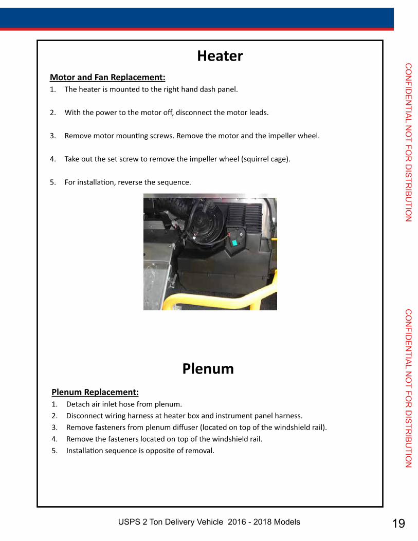
HeaterMotor and Fan Replacement:1. The heater is mounted to the right hand dash panel.
2. With the power to the motor off, disconnect the motor leads.
3. Remove motor mounting screws. Remove the motor and the impeller wheel.
4. Take out the set screw to remove the impeller wheel (squirrel cage).
5. For installation, reverse the sequence.
Plenum Replacement:1. Detach air inlet hose from plenum.2. Disconnect wiring harness at heater box and instrument panel harness.3. Remove fasteners from plenum diffuser (located on top of the windshield rail).4. Remove the fasteners located on top of the windshield rail.5. Installation sequence is opposite of removal.
Plenum
20 Genuine OEM Parts 1.800.233.4823 www.morganolsonparts.com
CO
NFI
DEN
TIAL
NO
T FO
R D
ISTR
IBU
TIO
N
C
ON
FID
ENTI
AL N
OT
FOR
DIS
TRIB
UTI
ON
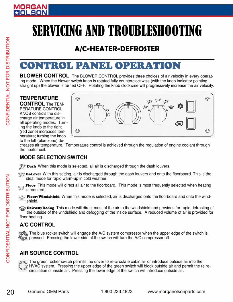
BLOWER CONTROL The BLOWER CONTROL provides three choices of air velocity in every operat-ing mode. When the blower switch knob is rotated fully counterclockwise (with the knob indicator pointing straight up) the blower is turned OFF. Rotating the knob clockwise will progressively increase the air velocity.
TEMPERATURE CONTROL The TEM-PERATURE CONTROL KNOB controls the dis-charge air temperature in all operating modes. Turn-ing the knob to the right (red zone) increases tem-to the left (blue zone) de-creases air temperature. Temperature control is achieved through the regulation of engine coolant through the heater coil.
MODE SELECTION SWITCH
When this mode is selected, all air is discharged through the dash louvers.
With this setting, air is discharged through the dash louvers and onto the floorboard. This is the ideal mode for rapid warm-up in cold weather.
This mode will direct all air to the floorboard. This mode is most frequently selected when heating is required.
When this mode is selected, air is discharged onto the floorboard and onto the wind-shield.
This mode will direct most of the air to the windshield and provides for rapid defrosting of the outside of the windshield and defogging of the inside surface. A reduced volume of air is provided for
floor heating.
A/C CONTROL
The blue rocker switch will engage the A/C system compressor when the upper edge of the switch is pressed. Pressing the lower side of the switch will turn the A/C compressor off.
AIR SOURCE CONTROL
The green rocker switch permits the driver to re-circulate cabin air or introduce outside air into the HVAC system. Pressing the upper edge of the green switch will block outside air and permit the re re-circulation of inside air. Pressing the lower edge of the switch will introduce outside air.

21USPS 2 Ton Delivery Vehicle 2016 - 2018 Models
CO
NFID
ENTIAL N
OT FO
R D
ISTRIBU
TION
CO
NFID
ENTIAL N
OT FO
R D
ISTRIBU
TION
22 Genuine OEM Parts 1.800.233.4823 www.morganolsonparts.com
CO
NFI
DEN
TIAL
NO
T FO
R D
ISTR
IBU
TIO
N
C
ON
FID
ENTI
AL N
OT
FOR
DIS
TRIB
UTI
ON
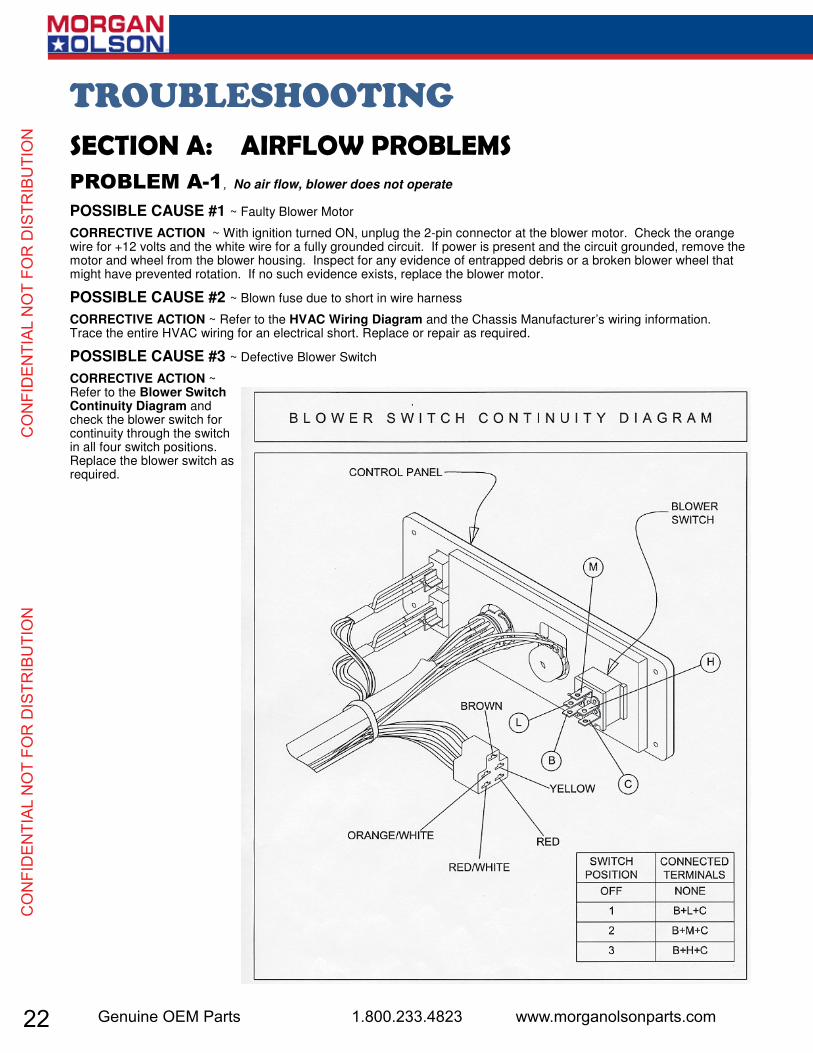
, No air flow, blower does not operate
POSSIBLE CAUSE #1 ~ Faulty Blower Motor
CORRECTIVE ACTION ~ With ignition turned ON, unplug the 2-pin connector at the blower motor. Check the orange wire for +12 volts and the white wire for a fully grounded circuit. If power is present and the circuit grounded, remove the motor and wheel from the blower housing. Inspect for any evidence of entrapped debris or a broken blower wheel that might have prevented rotation. If no such evidence exists, replace the blower motor.
POSSIBLE CAUSE #2 ~ Blown fuse due to short in wire harness
CORRECTIVE ACTION ~ Refer to the HVAC Wiring Diagram and the Chassis Manufacturer’s wiring information. Trace the entire HVAC wiring for an electrical short. Replace or repair as required.
POSSIBLE CAUSE #3 ~ Defective Blower Switch
CORRECTIVE ACTION ~ Refer to the Blower Switch Continuity Diagram and check the blower switch for continuity through the switch in all four switch positions. Replace the blower switch as required.

23USPS 2 Ton Delivery Vehicle 2016 - 2018 Models
CO
NFID
ENTIAL N
OT FO
R D
ISTRIBU
TION
CO
NFID
ENTIAL N
OT FO
R D
ISTRIBU
TION
, Blower operates, but not in all blower switch settings
POSSIBLE CAUSE #1 ~ Blower resistor failure.
CORRECTIVE ACTION ~ If the blower operates only on the highest blower speed (blower switch rotated fully clock-wise), the blower resistor has, most likely, failed. [Hint: The resistor is bypassed when the highest blower speed is select-ed.] Refer to the Blower Motor Resistor -wire connector from the resistor. Check for electrical continuity between terminal 1 and 2. If an open circuit exists between 1 and 2, the thermal limiter has blown and it will be necessary to replace the resistor. [Note: A failed resistor is often the results of a problem with the blower motor. Make sure that the blower motor is fully operable and is not bound in any sort of way by a broken blower wheel or entrapped debris within the blower housing.]
POSSIBLE CAUSE #2 ~ High-blower relay failure
CORRECTIVE ACTION ~ If the blower operates in all speed selections except for the highest selection there is a possi-
bility that the high-blower relay has failed. [Note: The high-blower relay is activated when the highest blower speed is
selected. The relay extends the life of the blower switch and insures the highest voltage for the motor.] Remove the re-
lay and test for an open circuit across terminals 85 and 86. If the circuit is open, replace the relay.
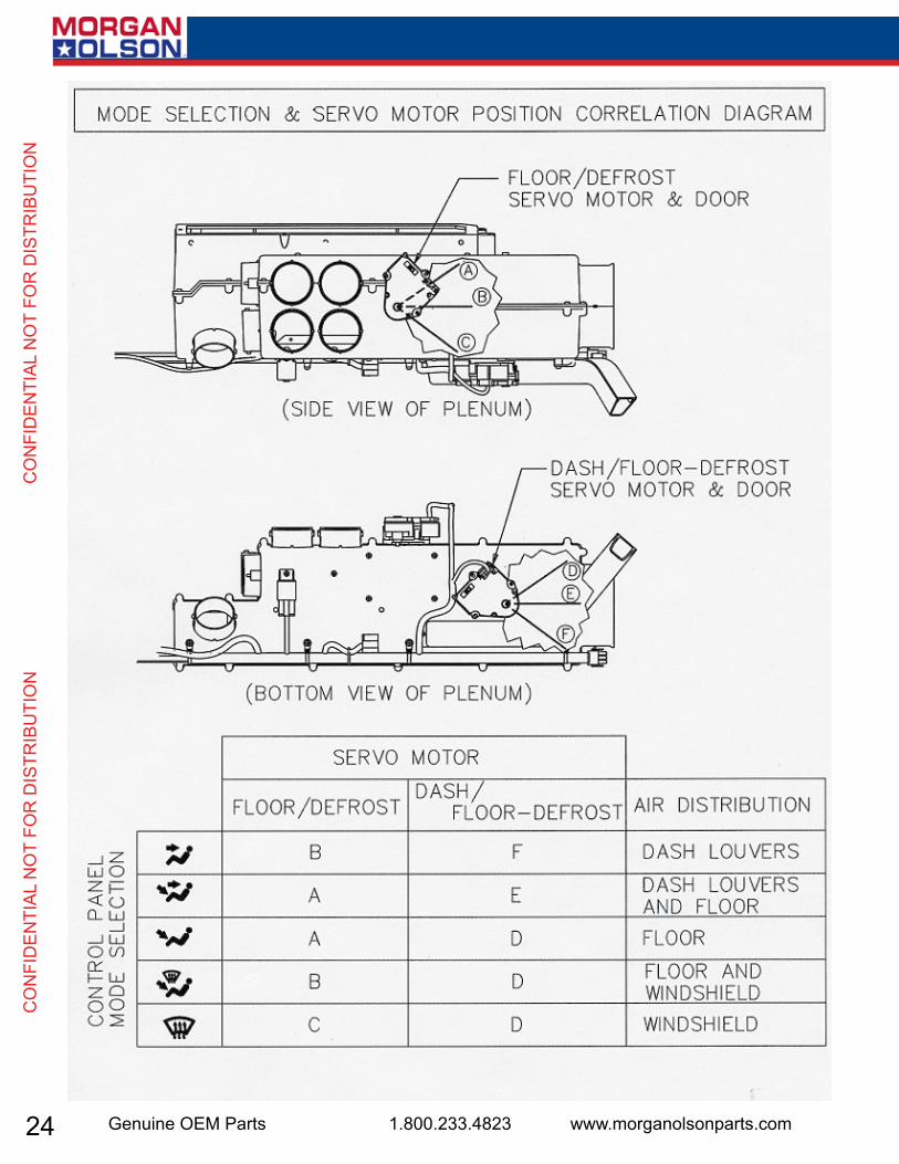
~ Air does not flow from the selected outlets
POSSIBLE CAUSE #1 ~ Plenum directional doors obstructed
CORRECTIVE ACTION ~ Examine the air distribution Plenum for any possible obstruction that might have become en-
trapped internally. Refer to the Mode Selection & Servo Motor Position Correlation Diagram for the position of each
of the doors in every mode selection. The output shafts of the servo motors can be observed, externally, as they move
through their approximate 100 degrees of travel. Also, the doors can be physically touched by removing the 5” flexible
inlet duct and reaching into the plenum’s air intake. If a physical obstruction is suspected, it may be necessary to re-
move the plenum. [Note: Access to the plenum’s mounting hardware will require removal of the defroster ducts from
atop the dash.]
24 Genuine OEM Parts 1.800.233.4823 www.morganolsonparts.com
CO
NFI
DEN
TIAL
NO
T FO
R D
ISTR
IBU
TIO
N
C
ON
FID
ENTI
AL N
OT
FOR
DIS
TRIB
UTI
ON
25USPS 2 Ton Delivery Vehicle 2016 - 2018 Models
CO
NFID
ENTIAL N
OT FO
R D
ISTRIBU
TION
CO
NFID
ENTIAL N
OT FO
R D
ISTRIBU
TION
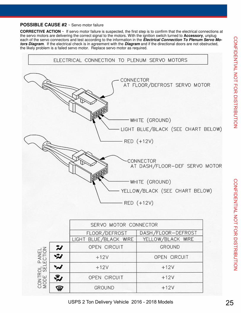
POSSIBLE CAUSE #2 ~ Servo motor failure
CORRECTIVE ACTION ~ If servo motor failure is suspected, the first step is to confirm that the electrical connections at the servo motors are delivering the correct signal to the motors. With the ignition switch turned to Accessory, unplug each of the servo connectors and test according to the information in the Electrical Connection To Plenum Servo Mo-tors Diagram. If the electrical check is in agreement with the Diagram and if the directional doors are not obstructed, the likely problem is a failed servo motor. Replace servo motor as required.
26 Genuine OEM Parts 1.800.233.4823 www.morganolsonparts.com
CO
NFI
DEN
TIAL
NO
T FO
R D
ISTR
IBU
TIO
N
C
ON
FID
ENTI
AL N
OT
FOR
DIS
TRIB
UTI
ON
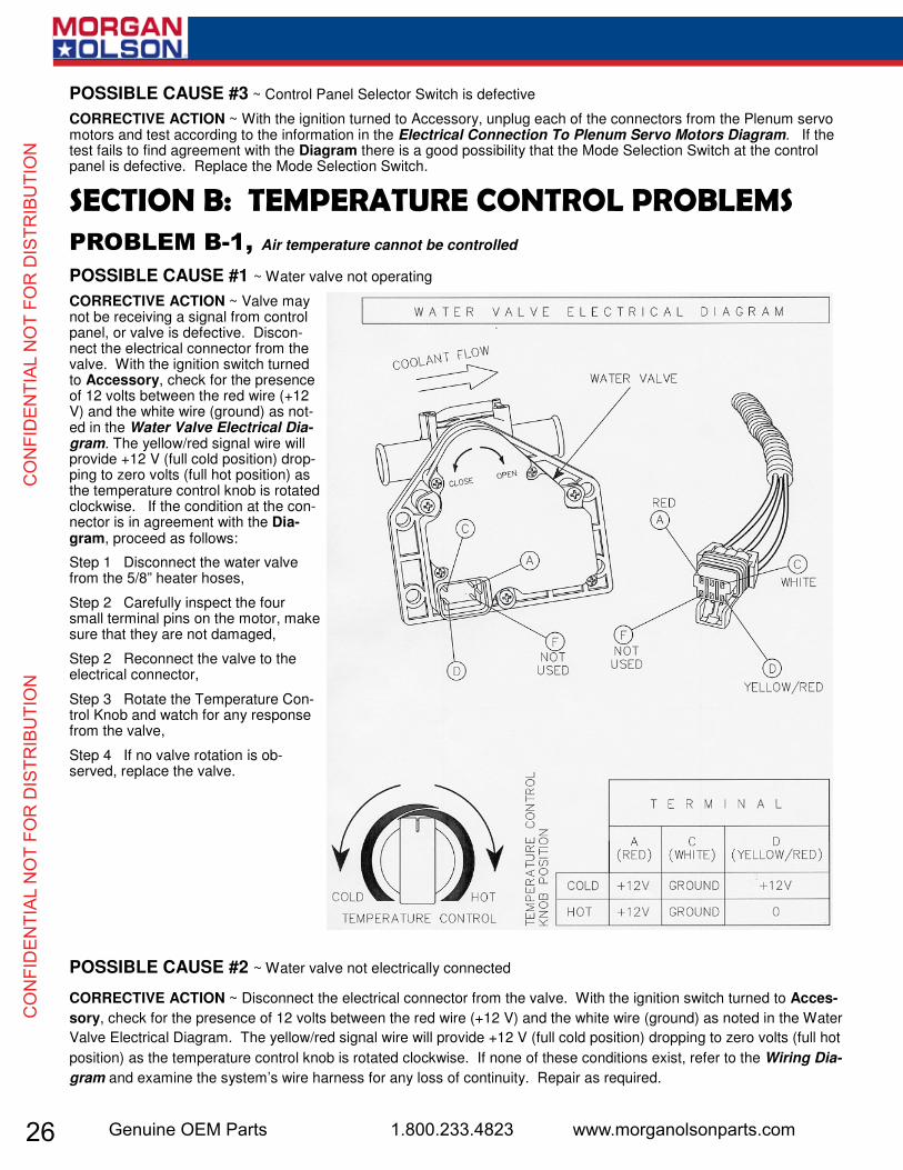
POSSIBLE CAUSE #3 ~ Control Panel Selector Switch is defective
CORRECTIVE ACTION ~ With the ignition turned to Accessory, unplug each of the connectors from the Plenum servo motors and test according to the information in the Electrical Connection To Plenum Servo Motors Diagram. If the test fails to find agreement with the Diagram there is a good possibility that the Mode Selection Switch at the control panel is defective. Replace the Mode Selection Switch.
Air temperature cannot be controlled
POSSIBLE CAUSE #1 ~ Water valve not operating
CORRECTIVE ACTION ~ Valve may not be receiving a signal from control panel, or valve is defective. Discon-nect the electrical connector from the valve. With the ignition switch turned to Accessory, check for the presence of 12 volts between the red wire (+12 V) and the white wire (ground) as not-ed in the Water Valve Electrical Dia-gram. The yellow/red signal wire will provide +12 V (full cold position) drop-ping to zero volts (full hot position) as the temperature control knob is rotated clockwise. If the condition at the con-nector is in agreement with the Dia-gram, proceed as follows:
Step 1 Disconnect the water valve from the 5/8” heater hoses,
Step 2 Carefully inspect the four small terminal pins on the motor, make sure that they are not damaged,
Step 2 Reconnect the valve to the electrical connector,
Step 3 Rotate the Temperature Con-trol Knob and watch for any response from the valve,
Step 4 If no valve rotation is ob-served, replace the valve.
POSSIBLE CAUSE #2 ~ Water valve not electrically connected
CORRECTIVE ACTION ~ Disconnect the electrical connector from the valve. With the ignition switch turned to Acces-
sory, check for the presence of 12 volts between the red wire (+12 V) and the white wire (ground) as noted in the Water
Valve Electrical Diagram. The yellow/red signal wire will provide +12 V (full cold position) dropping to zero volts (full hot
position) as the temperature control knob is rotated clockwise. If none of these conditions exist, refer to the Wiring Dia-
gram and examine the system’s wire harness for any loss of continuity. Repair as required.

27USPS 2 Ton Delivery Vehicle 2016 - 2018 Models
CO
NFID
ENTIAL N
OT FO
R D
ISTRIBU
TION
CO
NFID
ENTIAL N
OT FO
R D
ISTRIBU
TION
, A/C system not providing cool air
POSSIBLE CAUSE #1 ~ Loss of refrigerant
CORRECTIVE ACTION ~ Verify the presence of 1.75 pounds of refrigerant R134a. If the AC system is either partially low, or completely empty, a search will be required for leakage. Replace and repair as required.
POSSIBLE CAUSE #2 ~ Compressor not engaged
CORRECTIVE ACTION ~ Confirm that the system is fully charged. With the ignition switch turned to Accessory, the blower switch turned to the highest speed and the AC (blue) rocker switch engaged, proceed as follows:
Step 1: Check for the presence of 12 volts at the compressor. If yes, make certain that the compressor clutch is fully grounded. If the ground circuit is intact, the compressor clutch has, most likely, failed and requires replacement.
Step 2: If no voltage is present at the compressor clutch, refer to the Wiring Diagram and check for voltage at each of the system pressure switches.[Note: The low pressure switch is located on the suction hose near the firewall and opens on a pressure drop to 8 psi. The binary (high/low) pressure switch is located on the liquid hose near the receiver/drier and opens on a pressure rise to approximately 400 psi and a pressure drop to 28 psi.] With the system fully charged, there should be continuity through both switches. Replace as required.
Step 3: If no voltage is present at the pressure switches, check for voltage at the thermostat (located externally on the HVAC housing). Assuming that the evaporator coil is fully warmed to ambient conditions, the thermostat should be a closed circuit. [Note: The thermostat circuit opens when the evaporator coil surface temperature drops below 32 de-circuit, replacement is required. Thermostat replacement requires the complete removal and disassembly of the HVAC housing. When replacing thermostat, take special care to not kink the capillary tube. Also, install the new capillary tube in the same location as the original.
POSSIBLE CAUSE #3 ~ Perceived lack of cooling due to extreme conditions
CORRECTIVE ACTION ~ Note that extremely high humidity can reduce the effectiveness of the evaporator. The Am-bient Temperature vs. Relative Humidity Chart (below) illustrates how very high humidity can raise the louver tem-peratures. This test is best performed with the doors and windows open, the blower turned to the highest speed and the AC system fully engaged. Run the engine at 1500 rpm and allow time for the system to stabilize. Measure the dis-charge air temperature at one of the dash louvers and compare to the Chart.
28 Genuine OEM Parts 1.800.233.4823 www.morganolsonparts.com
CO
NFI
DEN
TIAL
NO
T FO
R D
ISTR
IBU
TIO
N
C
ON
FID
ENTI
AL N
OT
FOR
DIS
TRIB
UTI
ON
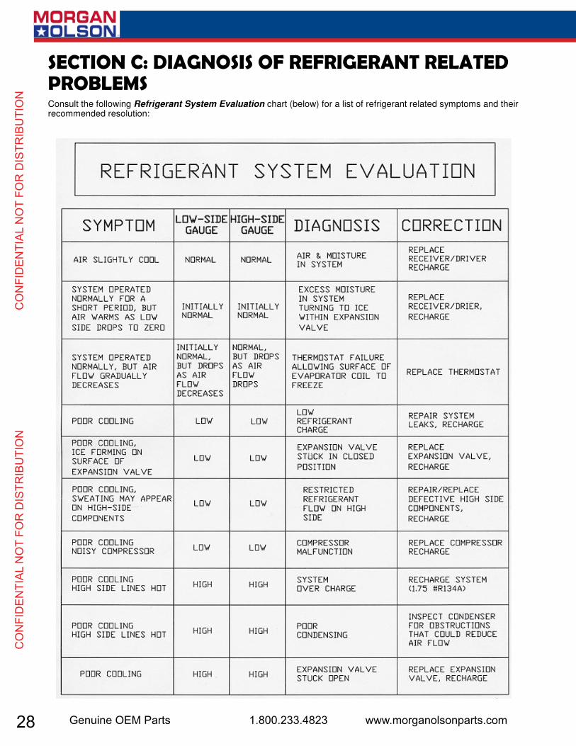
Consult the following Refrigerant System Evaluation chart (below) for a list of refrigerant related symptoms and their recommended resolution:
29USPS 2 Ton Delivery Vehicle 2016 - 2018 Models
CO
NFID
ENTIAL N
OT FO
R D
ISTRIBU
TION
CO
NFID
ENTIAL N
OT FO
R D
ISTRIBU
TION
30 Genuine OEM Parts 1.800.233.4823 www.morganolsonparts.com
CO
NFI
DEN
TIAL
NO
T FO
R D
ISTR
IBU
TIO
N
C
ON
FID
ENTI
AL N
OT
FOR
DIS
TRIB
UTI
ON
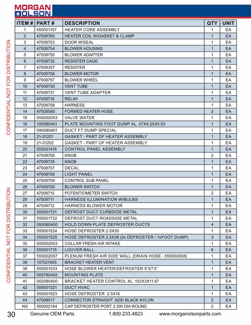
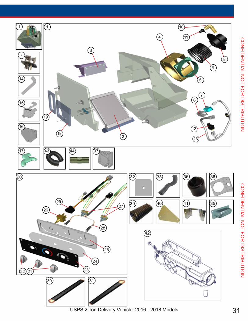
ITEM # PART # DESCRIPTION QTY UNIT1 555001107 heateR coRe assembLy 1 ea2 47008760 heateR coiL W/gasket & cLamP 1 ea3 47008753 dooR W/seaL 1 ea4 47008754 bLoWeR housiNg 1 ea5 47008755 bLoWeR adaPteR 1 ea6 47008732 ResisteR cage 1 ea7 47008357 ResisteR 1 ea8 47008756 bLoWeR motoR 1 ea9 47008757 bLoWeR WheeL 1 ea10 47008730 veNt tube 1 ea11 47008731 veNt tube adaPteR 1 ea12 47008716 ReLay 1 ea13 47008758 haRNess 1 ea14 47008580 foRmed heateR hose 2 ea15 555002053 vaLve WateR 1 ea16 105080401 PLate mouNtiNg foot dumP aL .07x4.25x5.53 1 ea17 090080401 duct ft dumP sPeciaL 1 ea18 21-01201 gasket - PaRt of heateR assembLy 1 ea19 21-01202 gasket - PaRt of heateR assembLy 1 ea20 555001416 coNtRoL PaNeL assembLy 1 ea21 47008706 kNob 2 ea22 47008735 kNob 1 ea23 47008707 decaL 1 ea24 47008708 Light PaNeL 1 ea25 47008709 coNtRoL sub PaNeL 1 ea26 47008700 bLoWeR sWitch 1 ea27 47008710 PoteNtiometeR sWitch 2 ea28 47008711 haRNess iLLumiNatioN W/buLbs 1 ea29 47008712 haRNess bLoWeR motoR 1 ea30 555001721 defRost duct cuRbside metaL 1 ea31 555001722 defRost duct Roadside metaL 1 ea32 093080400 hoLd doWN PLate defRosteR ducts 4 ea33 555001524 hose defRosteR 2.5x30 1 ea34 555001525 hose defRosteR 2.5x38 (2x defRosteR / 1xfoot dumP) 3 ea35 555002003 coLLaR fResh aiR iNtake 1 ea36 555001715 LouveR baLL 6 ea37 555002007 PLeNum fResh aiR side WaLL (dRaiN hose - 555002008) 1 ea38 107027405 bRacket heateR veNt 1 ea39 555001533 hose bLoWeR heateR/defRosteR 5”x7.5” 1 ea40 005780402 mouNtiNg PLate 1 ea41 002080400 bRacket heateR coNtRoL aL .102x3x11.67 1 ea42 555001321 duct hvac 1 ea43 555001523 hose defRosteR 2.5x16 1 ea44 47008017 coNNectoR stRaight .62id bLack NyLoN 2 eaNs 555002164 caP defRosteR PoRt 2.5iN dia RouNd 2 ea
31USPS 2 Ton Delivery Vehicle 2016 - 2018 Models
CO
NFID
ENTIAL N
OT FO
R D
ISTRIBU
TION
CO
NFID
ENTIAL N
OT FO
R D
ISTRIBU
TION
10
114
3
1
19
182
12
13
67
5
9
87
14
1
17
21 23
24
25
2627
28
29
30 31
32 36
42
38
39 40 41
22
33
35
20
16
15
43 44 37
32 Genuine OEM Parts 1.800.233.4823 www.morganolsonparts.com
CO
NFI
DEN
TIAL
NO
T FO
R D
ISTR
IBU
TIO
N
C
ON
FID
ENTI
AL N
OT
FOR
DIS
TRIB
UTI
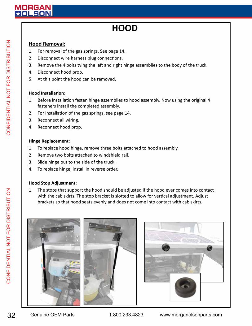
ON Hood Removal:
1. For removal of the gas springs. See page 14.2. Disconnect wire harness plug connections.3. Remove the 4 bolts tying the left and right hinge assemblies to the body of the truck.4. Disconnect hood prop.5. At this point the hood can be removed.
Hood Installation:1. Before installation fasten hinge assemblies to hood assembly. Now using the original 4
fasteners install the completed assembly.2. For installation of the gas springs, see page 14.3. Reconnect all wiring.4. Reconnect hood prop.
Hinge Replacement:1. To replace hood hinge, remove three bolts attached to hood assembly.2. Remove two bolts attached to windshield rail.3. Slide hinge out to the side of the truck.4. To replace hinge, install in reverse order.
Hood Stop Adjustment:1. The stops that support the hood should be adjusted if the hood ever comes into contact
with the cab skirts. The stop bracket is slotted to allow for vertical adjustment. Adjust brackets so that hood seats evenly and does not come into contact with cab skirts.
HOOD
33USPS 2 Ton Delivery Vehicle 2016 - 2018 Models
CO
NFID
ENTIAL N
OT FO
R D
ISTRIBU
TION
CO
NFID
ENTIAL N
OT FO
R D
ISTRIBU
TION
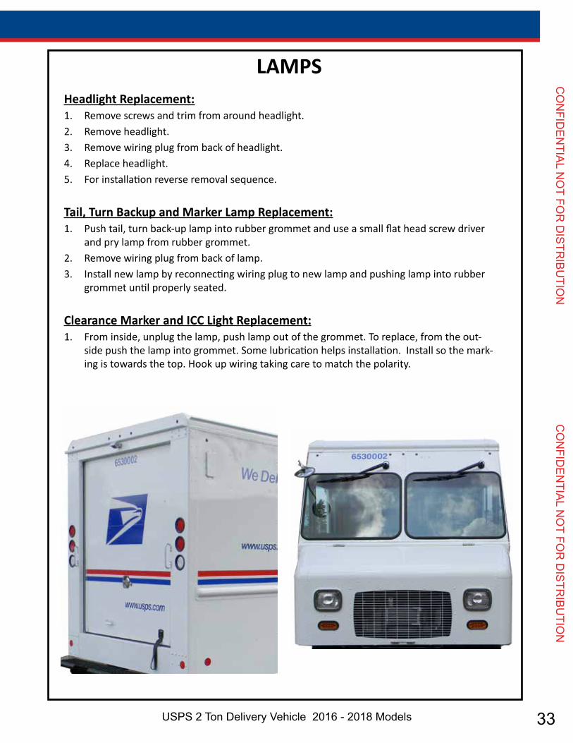
Headlight Replacement:1. Remove screws and trim from around headlight.2. Remove headlight.3. Remove wiring plug from back of headlight.4. Replace headlight.5. For installation reverse removal sequence.
Tail, Turn Backup and Marker Lamp Replacement:1. Push tail, turn back-up lamp into rubber grommet and use a small flat head screw driver
and pry lamp from rubber grommet. 2. Remove wiring plug from back of lamp.3. Install new lamp by reconnecting wiring plug to new lamp and pushing lamp into rubber
grommet until properly seated.
Clearance Marker and ICC Light Replacement:1. From inside, unplug the lamp, push lamp out of the grommet. To replace, from the out-
side push the lamp into grommet. Some lubrication helps installation. Install so the mark-ing is towards the top. Hook up wiring taking care to match the polarity.
LAMPS

34 Genuine OEM Parts 1.800.233.4823 www.morganolsonparts.com
CO
NFI
DEN
TIAL
NO
T FO
R D
ISTR
IBU
TIO
N
C
ON
FID
ENTI
AL N
OT
FOR
DIS
TRIB
UTI
ON Body Panel Replacement:
1. When replacing exterior body panels, remove rivets following procedures outlined below.2. Apply sealant to new panel as required.3. Install new panel in reverse order.
Removing A Rivet:1. When removing an existing rivet, place the drill bit on the small dot in the center of the
rivet head. Twist the drill chuck by hand to enlarge the small dot. This will prevent the drill from slipping.
2. *Never drill completely through the rivet or you risk enlarging the hole which can weaken the bond when re-fastened. Drill into the center of the rivet head. With drill turned off but still in place, move it horizontally and vertically until the head of the rivet comes off. Use an awl and a mallet to tap the rivet shank out.
3. If you accidentally drill through the material, see the following instructions.
Re-Riveting:1. When replacing new panels, use .19 diameter rivets. The correct length rivet will measure
.25-.38 beyond the material being joined. (See diagram below)2. When ever rivets are removed there is always some enlargement to the hole. To ensure
the strength of the new bond, follow these steps.3. Drill the hole out to .25” diameter. If the hole is already .25” diameter then drill it out to
.28” diameter and use a .25” bolt and nut, otherwise continue to the next step.4. Rivet the parts using a .25” rivet. The correct length rivet will measure .25-.38 beyond the
material being joined.NOTE: As the vehicle ages, it is not uncommon for some rivets to loosen. This can often be detected by a black ring (aluminum oxide) around the head of the rivet. If this happens replace the rivet. See Re-Riveting.
BODY PANEL REPLACEMENTS & RIVETS
35USPS 2 Ton Delivery Vehicle 2016 - 2018 Models
CO
NFID
ENTIAL N
OT FO
R D
ISTRIBU
TION
CO
NFID
ENTIAL N
OT FO
R D
ISTRIBU
TION
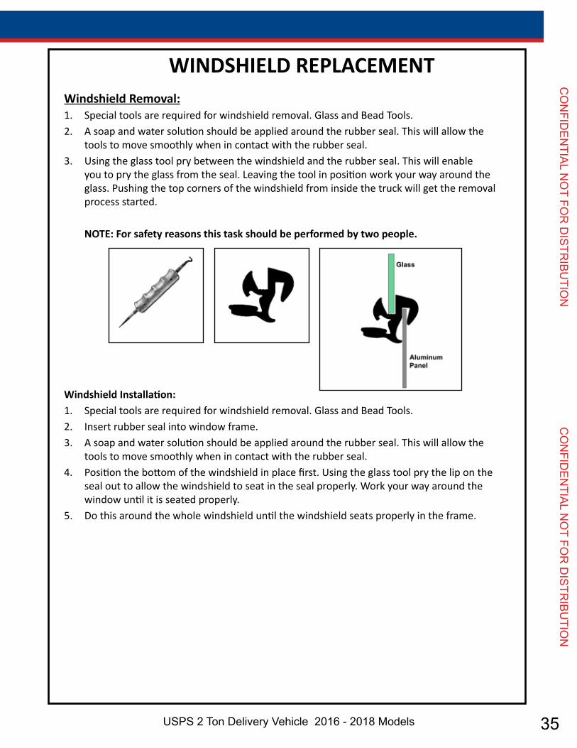
Windshield Removal:1. Special tools are required for windshield removal. Glass and Bead Tools.2. A soap and water solution should be applied around the rubber seal. This will allow the
tools to move smoothly when in contact with the rubber seal.3. Using the glass tool pry between the windshield and the rubber seal. This will enable
you to pry the glass from the seal. Leaving the tool in position work your way around the glass. Pushing the top corners of the windshield from inside the truck will get the removal process started.
NOTE: For safety reasons this task should be performed by two people.
Windshield Installation:1. Special tools are required for windshield removal. Glass and Bead Tools.2. Insert rubber seal into window frame.3. A soap and water solution should be applied around the rubber seal. This will allow the
tools to move smoothly when in contact with the rubber seal.4. Position the bottom of the windshield in place first. Using the glass tool pry the lip on the
seal out to allow the windshield to seat in the seal properly. Work your way around the window until it is seated properly.
5. Do this around the whole windshield until the windshield seats properly in the frame.
WINDSHIELD REPLACEMENT
36 Genuine OEM Parts 1.800.233.4823 www.morganolsonparts.com
CO
NFI
DEN
TIAL
NO
T FO
R D
ISTR
IBU
TIO
N
C
ON
FID
ENTI
AL N
OT
FOR
DIS
TRIB
UTI
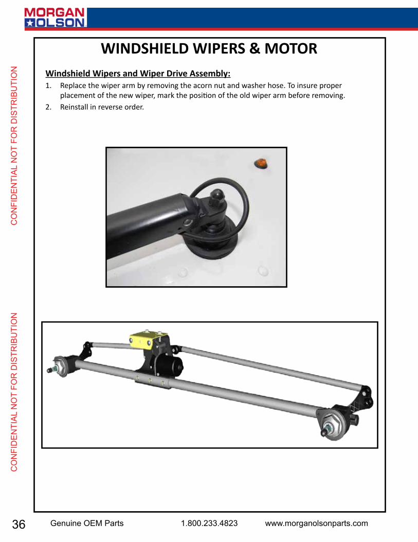
ON Windshield Wipers and Wiper Drive Assembly:
1. Replace the wiper arm by removing the acorn nut and washer hose. To insure proper placement of the new wiper, mark the position of the old wiper arm before removing.
2. Reinstall in reverse order.
WINDSHIELD WIPERS & MOTOR

37USPS 2 Ton Delivery Vehicle 2016 - 2018 Models
CO
NFID
ENTIAL N
OT FO
R D
ISTRIBU
TION
CO
NFID
ENTIAL N
OT FO
R D
ISTRIBU
TION
LIFT-GATE If anyone observes improper installation, improper operation, or damage, they should immediately contact a qualified person for assistance and correction. We strongly urge anyone that has any questions or doubts as to the installation, condition, use, operation, maintenance or repair of the lift-gate to contact us at Waltco where we have qualified personnel that will be happy to assist you. Telephone numbers and address-es of these locations are listed in the Owner’s Manual and Installation Instructions.
INSTALLATION Waltco lift-gates should only be installed by those with sufficient basic skills to understand the installation and operation of the lift-gate, along with the equipment on which the lift-gate is being installed. Waltco’s installation instructions are not intended to give rationale for all the instructions that are given; however, it is the intent of these instructions to give the installer both the operations and what we believe to be the most desirable sequence of implementing these operations. These instructions can in no way expand into an area where they will replace a qualified person, or clear thinking and a basic knowledge that must be possessed by the installer. It has been our experience that a knowledgeable journeyman following these instructions and observing the operation of the lift-gate will have a sufficient comprehension of the lift-gate to enable this person to troubleshoot and correct all normal problems that may be encountered.Failure to follow the installation instructions, adjustments and mounting dimensions may result in improper and unsafe operation of the lift-gate. Unauthorized alterations of the lift-gate can cause an undesirable and dangerous condition. OWNER’S MANUAL The Waltco Owner’s Manual is intended to act as a guide for operation and routine maintenance but is no way intended to encourage usage or repair of the lift-gate by those who are not qualified to do so. The contents of the owner’s manual include, but are not limited to general operation instructions, routine lubrication, parts lists, and an outline of things that should be checked but may not be obvious to those not technically qualified. This manual assumes the lift-gate is properly installed, undamaged and oper-ates correctly. Improper installation, improper operation, or damage should be immediately corrected by a qualified person. INSPECTION As part of the regular inspection of a lift-gate and after damage or suspicion of an overload, inspect for wear or structural damage and make necessary repairs or replacements. Check all structural components and their attachment to the lift-gate for cracked welds, loose fasteners, wear and part deformation. Check cylinder and hose for leaks. Inspections and repairs should be made by a qualified mechanic.
REPLACEMENT PARTS Use only Waltco original equipment replacement parts. Components of other lift-gate manufactur-ers may outwardly appear to be the same but are not interchangeable with Waltco products. Waltco compo-nents are specifically designed for safety requirements, reliability and compatibility with our products. Refer to your Waltco parts manual when ordering parts. NOTE: When ordering, give model and serial number of lift-gate.
DECALS It is important that every vehicle that has a WALTCO Lift gate have legible DECALS clearly posted on the vehicle and an OWNER’S MANUAL in the vehicle at all times as a guide for proper operation and mainte-nance.
38 Genuine OEM Parts 1.800.233.4823 www.morganolsonparts.com
CO
NFI
DEN
TIAL
NO
T FO
R D
ISTR
IBU
TIO
N
C
ON
FID
ENTI
AL N
OT
FOR
DIS
TRIB
UTI
ON WARNING
Read, understand, and follow all of the warning listed below. Failure to follow these warning could result in severe personal injury or death.• Read and understand the Owner’s Manual, all decals and warning on lift-gate before operating lift-gate.
• Do not operate lift-gate without a thorough knowledge and understanding of the operation of the lift-gate.
• Lift gate hazards can result in crushing or falling.
• This lift-gate is designed for loading and unloading of cargo. If personnel are required to ride lift-gate, observe and familiarize yourself with the lift-gate operation, decals and manuals. Ensure stable footing at all times.
• Do not ride lift-gate with unstable loads.
• Wheeled loads must be properly retained from rolling.
• Tall, high center of gravity loads must be retained from falling over.
• Never overload lift-gate: Load platform as close to the vehicle, and towards the middle of the platform as possible. Refer to owner’s manual and capacity decal of lift-gate for maximum load and load placement.
• Keep hands and feet clear of all potential pinch points.
• Never use lift-gate if it makes any unusual noise, has unusual vibration, raises or lowers unevenly, or fails to operate smoothly. Never use lift-gate if it shows any signs of structural damage such as cracked welds, bent or distorted members.
• Do not attempt any repairs unless you are qualified to do so. Care should be taken when work is performed on a disabled lift-gate located near moving traffic. When possible the vehicle should be moved away from traffic areas for repair. Precautionary measures should be taken to ensure personal safety including those recommended in Federal Motor Vehicle Safety Standards 571.125.
• When welding to lift-gate, or lift-gate components, take all necessary safety precautions, including using respiratory protection and other pertinent personal protective gear when welding harmful materials.
• All protective covers, guards, and safety devices must be in place and access doors closed before operating lift-gate.
• Do not allow anyone to stand in, or near area, in which Platform will open and close before opening or closing Platform.
• Do not allow anyone to stand near the Platform where a falling load could land on them.
• Platform is always to be properly stored and secured for transit. See the Owner’s Manual for details.
• Take care to retain cargo during transit for lift-gate Platforms which function as the tailgate or door of the cargo area. Small objects can fall through the space between the vehicle and the folded Platform.
• A Lock-Out device or Shut-Off Switch should always be used to prevent unauthorized use of lift-gate.
• For lift-gates with Runners, never use lift-gate if Runners do not travel freely and smoothly.
• For lift-gates with Roller Lifting Chain, the Chain should be replaced every (5) five years or 15,000 cycles, whichever comes first. Replace only with Waltco approved Roller Chain.
• Never transfer loads which exceed lifting capacity on or over any part of the Platform unless the lift-gate is equipped with a spe-cial reinforced Platform and Platform Support Bars for use when the Platform is used as loading ramp (dock board). Refer to the “Using Platform as a loading ramp” Chapter in the Operation Instructions of the BZ/RZ series Owner’s Manual.
• For lift-gates equipped with Trailer Hitches, never exceed the rated capacity of the hitch. Do not exceed the vehicle’s weight rating. Refer to the vehicle’s Owner’s Manual.
• Vehicle must comply with all state and federal standards.
• Follow the “Maintenance Guide” chapter in the Owner’s Manual.
SAFETY INFORMATION
39USPS 2 Ton Delivery Vehicle 2016 - 2018 Models
CO
NFID
ENTIAL N
OT FO
R D
ISTRIBU
TION
CO
NFID
ENTIAL N
OT FO
R D
ISTRIBU
TION
SAFETY INFORMATION
WARNINGLift-gates with Tilt Function• Proper use of the Control Switches is of extreme importance.
• Improper use of Tilt Switch could cause load to fall from the Platform or damage the lift-gate.
• Platform should be in a generally horizontal position when raising or lowering with a load.
• In any tilt position, the Platform may vary from level while raising or lowering the Platform.
Lift-gates equipped with spring operated Cam Closer • Replace Cam Release Spring every five (5) years or 15,000 cycles, whichever comes first.
RGL-Series Lift-gates• Make certain Platform Brake mechanisms are operating properly.
• The Runners are always to remain powered up against the Up stops Pins when in transit.
• Inspect Cables every three (3) months or 750 cycles, whichever comes first. Cables must be replaced if they show signs of wear, distortion, kinking or if any broken wires are visible.
• Replace cables every five (5) years or 10,000 cycles, whichever comes first.
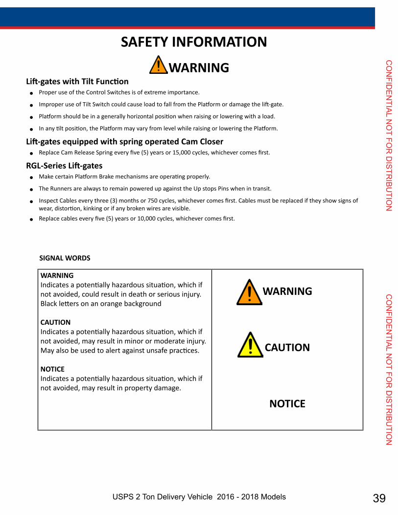
WARNINGIndicates a potentially hazardous situation, which if not avoided, could result in death or serious injury.Black letters on an orange background
CAUTIONIndicates a potentially hazardous situation, which if not avoided, may result in minor or moderate injury. May also be used to alert against unsafe practices.
NOTICEIndicates a potentially hazardous situation, which if not avoided, may result in property damage.
WARNING
CAUTION
NOTICE
SIGNAL WORDS

40 Genuine OEM Parts 1.800.233.4823 www.morganolsonparts.com
CO
NFI
DEN
TIAL
NO
T FO
R D
ISTR
IBU
TIO
N
C
ON
FID
ENTI
AL N
OT
FOR
DIS
TRIB
UTI
ON
WALTCO Warranty Policy
WALTCO warrants its products free of defects in materials and workmanship. WALTCO will replace components found defective during the warranty period. Labor will be reimbursed according to our flat rate labor schedule at the prevailing shop rate. Contact our Sales or Warranty departments for the warranty period of your model or for information regarding our flat rate labor schedule.
WALTCO Warranty Claim Procedure For consideration, all claims must be received within 30 days of repair and include the following information:
Liftgate Serial Number Description of problem and corrective actions Itemization of the labor charge to include the number of hours and labor rate
Replacement warranty parts can be obtained by contacting Waltco’s Parts Department. Parts must be returned for inspection when requested. Exclusions: Waltco’s warranty does not include reimbursement for service calls, vehicle rental, towing, travel time, fabrication of parts available from WALTCO, damage from misuse or abuse, negligence, accidents, alteration, loss of income or overtime expense, oil, or normal wear. Diagnosis and troubleshooting time are included in the flat rate labor times. Warranty and technical information is available from WALTCO’s toll free customer service lines from 8:00 a.m. to 5:00 p.m. EST.
Waltco Lift Corp285 Northeast Ave, Box 354, Tallmadge, OH 44278
1-800-211-3074, 330-633-9191 Please visit our websites: http://www.waltco.com or http://www.hiab.com
We're behind you all the way!
Page 6
41USPS 2 Ton Delivery Vehicle 2016 - 2018 Models
CO
NFID
ENTIAL N
OT FO
R D
ISTRIBU
TION
CO
NFID
ENTIAL N
OT FO
R D
ISTRIBU
TION
Chapter 2 Liftgate Terminology
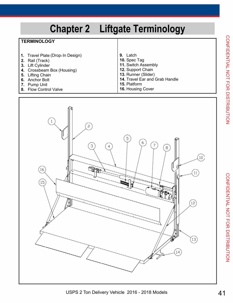
TERMINOLOGY
1. Travel Plate
(Drop-In Design) 2. Rail (Track)
3. Lift Cylinder 4. Crossbeam Box (Housing) 5. Lifting Chain 6. Anchor Bolt 7. Pump Unit 8. Flow Control Valve
9. Latch 10. Spec Tag 11. Switch Assembly 12. Support Chain 13. Runner (Slider) 14. Travel Ear and Grab Handle 15. Platform 16. Housing Cover
Page 7

42 Genuine OEM Parts 1.800.233.4823 www.morganolsonparts.com
CO
NFI
DEN
TIAL
NO
T FO
R D
ISTR
IBU
TIO
N
C
ON
FID
ENTI
AL N
OT
FOR
DIS
TRIB
UTI
ON
Chapter 2 Liftgate Terminology
Explanation of Specification Tag
Model Name Description Capacity MDL-10 Medium Duty Lift 1000 lbs.
GR00241
GR00241
MODEL NAME RATED CAPACITY Based on an evenly distributed load on the platform flat surface.
SERIAL NUMBER of liftgate. To be used
when ordering parts or when contacting Waltco for service or warranty
questions
DATE OF MANUFACTURE Month / Year
Page 8
43USPS 2 Ton Delivery Vehicle 2016 - 2018 Models
CO
NFID
ENTIAL N
OT FO
R D
ISTRIBU
TION
CO
NFID
ENTIAL N
OT FO
R D
ISTRIBU
TION
Chapter 3 Operation Instructions
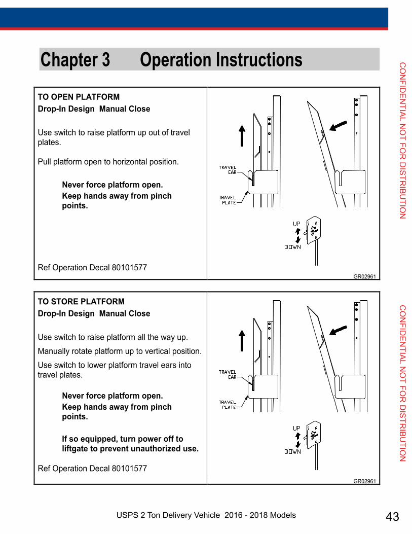
TO OPEN PLATFORM Drop-In Design Manual Close Use switch to raise platform up out of travel plates. Pull platform open to horizontal position.
Never force platform open. Keep hands away from pinch points.
Ref Operation Decal 80101577 GR02961
Page 9
TO STORE PLATFORM Drop-In Design Manual Close Use switch to raise platform all the way up. Manually rotate platform up to vertical position. Use switch to lower platform travel ears into travel plates.
Never force platform open. Keep hands away from pinch points.
If so equipped, turn power off to liftgate to prevent unauthorized use.
Ref Operation Decal 80101577 GR02961

44 Genuine OEM Parts 1.800.233.4823 www.morganolsonparts.com
CO
NFI
DEN
TIAL
NO
T FO
R D
ISTR
IBU
TIO
N
C
ON
FID
ENTI
AL N
OT
FOR
DIS
TRIB
UTI
ON Chapter 3 Operation Instructions
Page 10
LOADING OF PLATFORM
Load and unload from rear of platform and not side of platform. Never remove side linkage to load or unload platform.
Always load as close to center of platform and as close to truck sill as possible.
Never operate lift trucks on or over any part of platform.
This unit is intended for loading and unloaded of cargo only. Do not use for anything but its intended use.
GR02844
POWER OFF TO LIFTGATE (OPTIONAL SWITCH) Turn power off to liftgate by turning off the Cab Shut-Off switch inside the cab of vehicle. This may be a toggle or rotary type switch.
Turn power off to liftgate to prevent unauthorized use of liftgate.
GR00379
Cab Shut Off Switch
OPERATION INSTRUCTIONS
45USPS 2 Ton Delivery Vehicle 2016 - 2018 Models
CO
NFID
ENTIAL N
OT FO
R D
ISTRIBU
TION
CO
NFID
ENTIAL N
OT FO
R D
ISTRIBU
TION
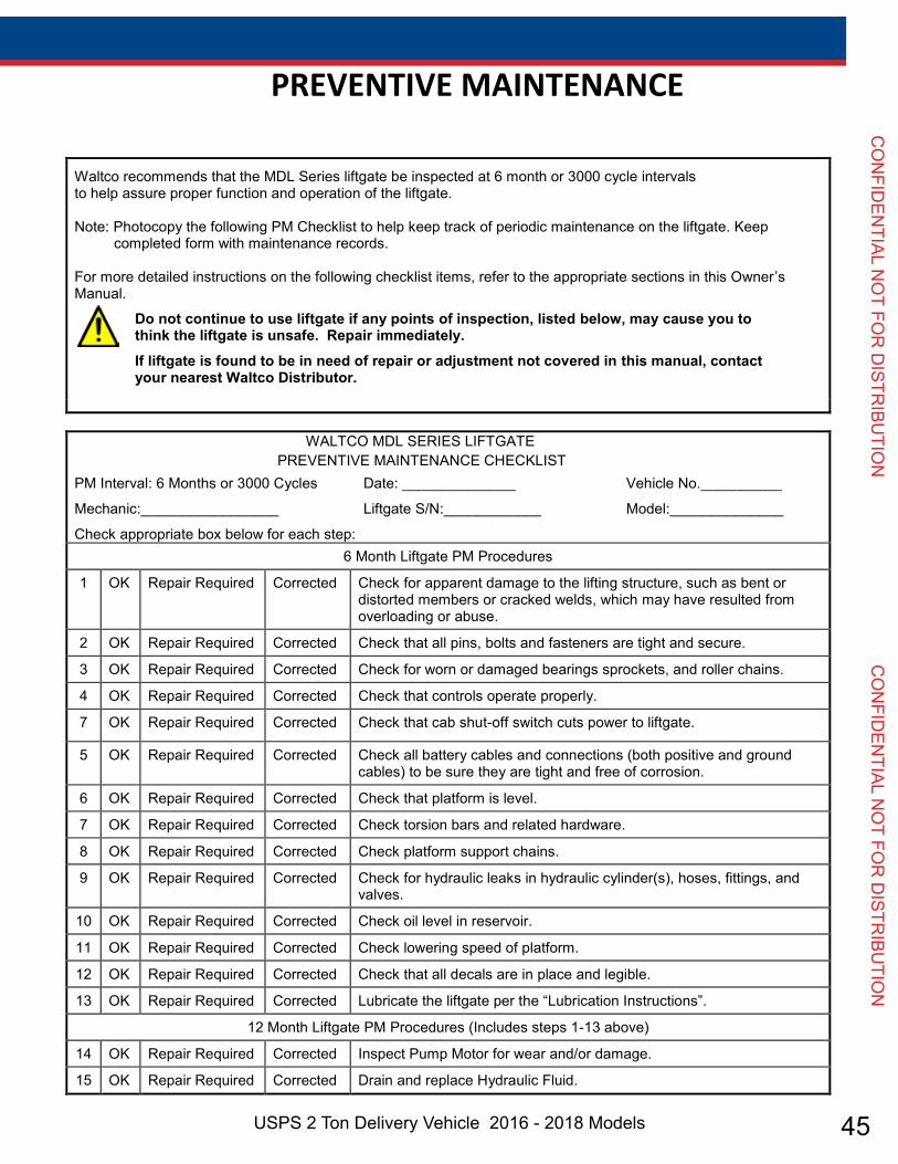
Chapter 4 Preventive Maintenance Waltco recommends that the MDL Series liftgate be inspected at 6 month or 3000 cycle intervals to help assure proper function and operation of the liftgate. Note: Photocopy the following PM Checklist to help keep track of periodic maintenance on the liftgate. Keep
completed form with maintenance records. For more detailed instructions on the following checklist items, refer to the appropriate sections in this Owner’s Manual.
Do not continue to use liftgate if any points of inspection, listed below, may cause you to think the liftgate is unsafe. Repair immediately.
If liftgate is found to be in need of repair or adjustment not covered in this manual, contact your nearest Waltco Distributor.
WALTCO MDL SERIES LIFTGATE PREVENTIVE MAINTENANCE CHECKLIST
PM Interval: 6 Months or 3000 Cycles Date: ______________ Vehicle No.__________
Mechanic:_________________ Liftgate S/N:____________ Model:______________
Check appropriate box below for each step: 6 Month Liftgate PM Procedures
1 OK Repair Required Corrected Check for apparent damage to the lifting structure, such as bent or distorted members or cracked welds, which may have resulted from overloading or abuse.
2 OK Repair Required Corrected Check that all pins, bolts and fasteners are tight and secure.
3 OK Repair Required Corrected Check for worn or damaged bearings sprockets, and roller chains.
4 OK Repair Required Corrected Check that controls operate properly.
7 OK Repair Required Corrected Check that cab shut-off switch cuts power to liftgate.
5 OK Repair Required Corrected Check all battery cables and connections (both positive and ground cables) to be sure they are tight and free of corrosion.
6 OK Repair Required Corrected Check that platform is level.
7 OK Repair Required Corrected Check torsion bars and related hardware.
8 OK Repair Required Corrected Check platform support chains.
9 OK Repair Required Corrected Check for hydraulic leaks in hydraulic cylinder(s), hoses, fittings, and valves.
10 OK Repair Required Corrected Check oil level in reservoir.
11 OK Repair Required Corrected Check lowering speed of platform.
12 OK Repair Required Corrected Check that all decals are in place and legible.
13 OK Repair Required Corrected Lubricate the liftgate per the “Lubrication Instructions”.
12 Month Liftgate PM Procedures (Includes steps 1-13 above)
14 OK Repair Required Corrected Inspect Pump Motor for wear and/or damage.
15 OK Repair Required Corrected Drain and replace Hydraulic Fluid.
Page 11
PREVENTIVE MAINTENANCE

46 Genuine OEM Parts 1.800.233.4823 www.morganolsonparts.com
CO
NFI
DEN
TIAL
NO
T FO
R D
ISTR
IBU
TIO
N
C
ON
FID
ENTI
AL N
OT
FOR
DIS
TRIB
UTI
ON
MONTHLY INSPECTION
Do not continue to use lift-gate if any points of inspection listed at left, or below, may cause you to think the lift-gate is un-
safe. Repair immediately.
If lift-gate is found to be in need of repair or adjustment not covered in this manual, contact your nearest Waltco Distributor.
Operate the lift-gate throughout its entire opera-tional cycle. Check for:
• Damage to lifting structure such as bent or distorted members or cracked welds.
• Worn or damaged roller chain, sprockets, and bearings.
• Bent or distorted pins or damaged cylin-der.
• Torsion bars are in place and properly working.
• All pivot and cylinder pins are securely in place, undamaged and retained by their proper fasteners.
• Damaged or worn bearings that pivot and cylinder pins rest in.
• Controls operate correctly (refer to chap-ter 3, “Operations Instructions”)
• Check all power cables, ground cables, and connections.
• Clean and tighten all loose connections. Replace any damaged or corroded wires or connectors.
PREVENTIVE MAINTENANCE

47USPS 2 Ton Delivery Vehicle 2016 - 2018 Models
CO
NFID
ENTIAL N
OT FO
R D
ISTRIBU
TION
CO
NFID
ENTIAL N
OT FO
R D
ISTRIBU
TION
PREVENTIVE MAINTENANCE
PLATFORM ADJUSTMENTUnfold and raise platform to bed level and check for:
1. If platform travels more than ¼” above the top of the crossbeam box, and lift-gate is not an Above Floor model lift-gate, see below for adjustment.
2. If platform is uneven see below for adjust-ment.
Lower platform to ground. Remove access cover from crossbeam box.
If lift-gate is Above Floor model: • Adjust as required to level platform.
If lift-gate is not an Above Floor model:• Adjust platform so it is level with top of
crossbeam box.
For non-Above Floor lift-gates, never adjust platform to travel above the crossbeam box.
Never adjust nut out less than 3/8” from end of anchor bolt.
Never have any part of your body under-neath the platform while making adjust-ments.
ABOVE FLOOR TRAVEL If above floor travel is to be reduced, additional links will need to be added to the lifting chains. If addi-tional above floor travel is desired, contact Waltco for assistance. Ability to increase travel varies with each specific model of lift-gate and bed height of vehicle.
48 Genuine OEM Parts 1.800.233.4823 www.morganolsonparts.com
CO
NFI
DEN
TIAL
NO
T FO
R D
ISTR
IBU
TIO
N
C
ON
FID
ENTI
AL N
OT
FOR
DIS
TRIB
UTI
ON
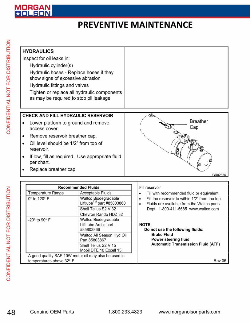
Chapter 4 Preventive Maintenance HYDRAULICS Inspect for oil leaks in:
Hydraulic cylinder(s) Hydraulic hoses - Replace hoses if they show signs of excessive abrasion Hydraulic fittings and valves Tighten or replace all hydraulic components as may be required to stop oil leakage
CHECK AND FILL HYDRAULIC RESERVOIR Lower platform to ground and remove
access cover. Remove reservoir breather cap. Oil level should be 1/2” from top of
reservoir. If low, fill as required. Use appropriate fluid
per chart. Replace breather cap.
GR02836
Recommended Fluids Fill reservoir Temperature Range Acceptable Fluids Fill with recommended fluid or equivalent. 0 to 120 F Waltco Biodegradable
LiftlubeTM part #85803860 Fill the reservoir to within 1/2” from the top.
Fluids are available from the Waltco parts Shell Tellus S2 V 32 Dept. 1-800-411-5685 www.waltco.com Chevron Rando HDZ 32 -20 to 90 F Waltco Biodegradable LiftLube Arctic part
#85803866 NOTE:
Do not use the following fluids: Waltco All Season Hyd Oil
Part 85803867 Shell Tellus S2 V 15 Mobil DTE 10 Excell 15
Brake Fluid Power steering fluid Automatic Transmission Fluid (ATF)
A good quality SAE 10W motor oil may also be used in temperatures above 32 F. Rev 06
Breather Cap
Page 14
PREVENTIVE MAINTENANCE
49USPS 2 Ton Delivery Vehicle 2016 - 2018 Models
CO
NFID
ENTIAL N
OT FO
R D
ISTRIBU
TION
CO
NFID
ENTIAL N
OT FO
R D
ISTRIBU
TION
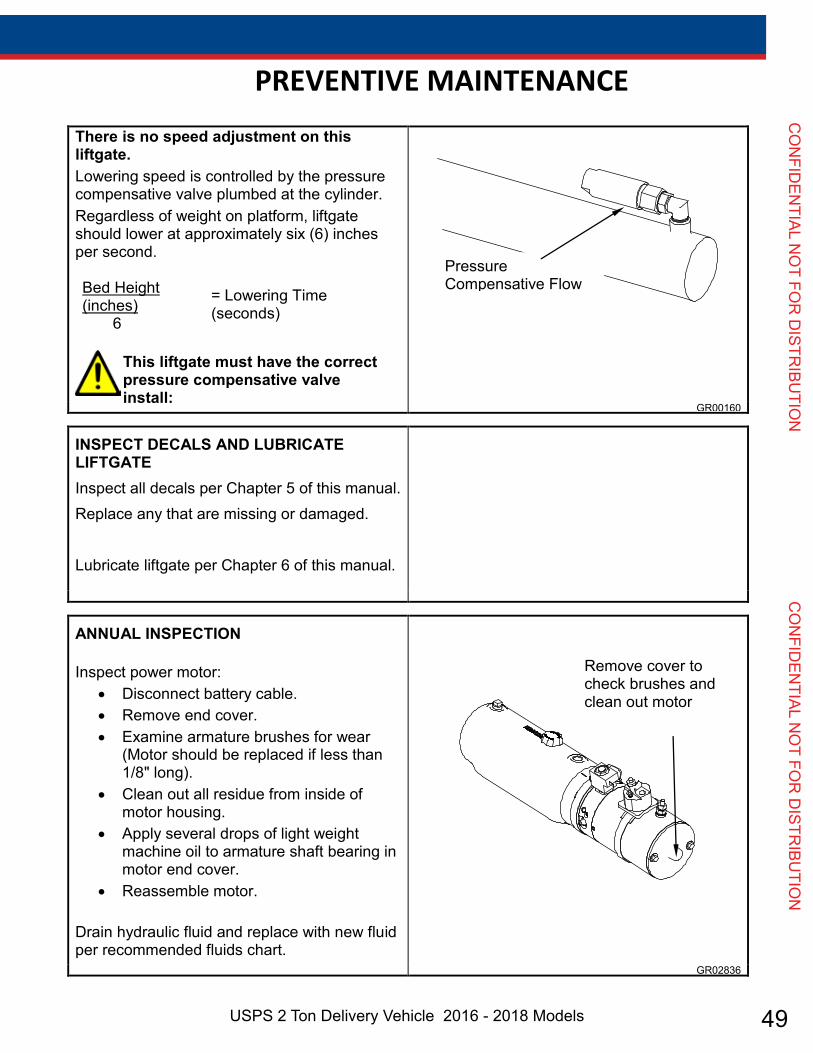
Chapter 4 Preventive Maintenance There is no speed adjustment on this liftgate. Lowering speed is controlled by the pressure compensative valve plumbed at the cylinder. Regardless of weight on platform, liftgate should lower at approximately six (6) inches per second. Bed Height (inches) = Lowering Time
(seconds) 6
This liftgate must have the correct pressure compensative valve install:
GR00160
INSPECT DECALS AND LUBRICATE LIFTGATEInspect all decals per Chapter 5 of this manual. Replace any that are missing or damaged. Lubricate liftgate per Chapter 6 of this manual.
ANNUAL INSPECTION Inspect power motor:
Disconnect battery cable. Remove end cover. Examine armature brushes for wear
(Motor should be replaced if less than 1/8" long).
Clean out all residue from inside of motor housing.
Apply several drops of light weight machine oil to armature shaft bearing in motor end cover.
Reassemble motor. Drain hydraulic fluid and replace with new fluid per recommended fluids chart.
GR02836
Pressure Compensative Flow Control Valve
Remove cover to check brushes and clean out motor
Page 15
PREVENTIVE MAINTENANCE
50 Genuine OEM Parts 1.800.233.4823 www.morganolsonparts.com
CO
NFI
DEN
TIAL
NO
T FO
R D
ISTR
IBU
TIO
N
C
ON
FID
ENTI
AL N
OT
FOR
DIS
TRIB
UTI
ON
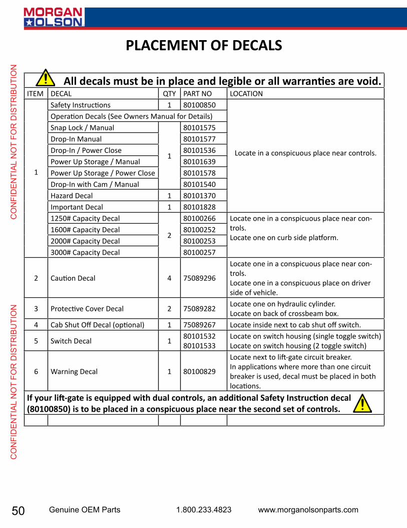
All decals must be in place and legible or all warranties are void.ITEM DECAL QTY PART NO LOCATION
1
Safety Instructions 1 80100850
Locate in a conspicuous place near controls.
Operation Decals (See Owners Manual for Details)Snap Lock / Manual
1
80101575Drop-In Manual 80101577Drop-In / Power Close 80101536Power Up Storage / Manual 80101639Power Up Storage / Power Close 80101578Drop-In with Cam / Manual 80101540Hazard Decal 1 80101370Important Decal 1 801018281250# Capacity Decal
2
80100266 Locate one in a conspicuous place near con-trols.Locate one on curb side platform.
1600# Capacity Decal 801002522000# Capacity Decal 801002533000# Capacity Decal 80100257
2 Caution Decal 4 75089296
Locate one in a conspicuous place near con-trols.Locate one in a conspicuous place on driver side of vehicle.
3 Protective Cover Decal 2 75089282 Locate one on hydraulic cylinder.Locate on back of crossbeam box.
4 Cab Shut Off Decal (optional) 1 75089267 Locate inside next to cab shut off switch.
5 Switch Decal 1 8010153280101533
Locate on switch housing (single toggle switch)Locate on switch housing (2 toggle switch)
6 Warning Decal 1 80100829
Locate next to lift-gate circuit breaker.In applications where more than one circuit breaker is used, decal must be placed in both locations.
If your lift-gate is equipped with dual controls, an additional Safety Instruction decal (80100850) is to be placed in a conspicuous place near the second set of controls.
PLACEMENT OF DECALS

51USPS 2 Ton Delivery Vehicle 2016 - 2018 Models
CO
NFID
ENTIAL N
OT FO
R D
ISTRIBU
TION
CO
NFID
ENTIAL N
OT FO
R D
ISTRIBU
TION
PLACEMENT OF DECALS
52 Genuine OEM Parts 1.800.233.4823 www.morganolsonparts.com
CO
NFI
DEN
TIAL
NO
T FO
R D
ISTR
IBU
TIO
N
C
ON
FID
ENTI
AL N
OT
FOR
DIS
TRIB
UTI
ON
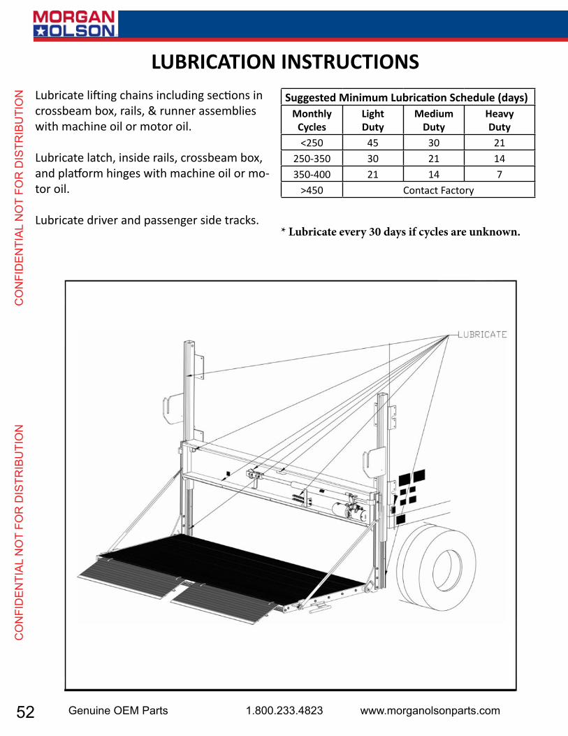
LUBRICATION INSTRUCTIONSLubricate lifting chains including sections in crossbeam box, rails, & runner assemblies with machine oil or motor oil.
Lubricate latch, inside rails, crossbeam box, and platform hinges with machine oil or mo-tor oil.
Lubricate driver and passenger side tracks.
Suggested Minimum Lubrication Schedule (days)Monthly
CyclesLightDuty
MediumDuty
HeavyDuty
<250 45 30 21250-350 30 21 14350-400 21 14 7
>450 Contact Factory
* Lubricate every 30 days if cycles are unknown.

53USPS 2 Ton Delivery Vehicle 2016 - 2018 Models
CO
NFID
ENTIAL N
OT FO
R D
ISTRIBU
TION
CO
NFID
ENTIAL N
OT FO
R D
ISTRIBU
TION
SCHEMATIC

54 Genuine OEM Parts 1.800.233.4823 www.morganolsonparts.com
CO
NFI
DEN
TIAL
NO
T FO
R D
ISTR
IBU
TIO
N
C
ON
FID
ENTI
AL N
OT
FOR
DIS
TRIB
UTI
ON
HYDRAULIC PUMP UNITITEM PART NUMBER QTY DESCRIPTION
1 70430695 hydraulic Pump unit, 14” reservoir Non-thermal switcha 70092312 1 motor, 12vb 43016835 1 Reservoir, 14”c 70092355 1 Relief valved 80001065 1 motor solenoide 70092503 1 valve, 2 way, 2 pos w/ coilf 75083364 1 elbow, 90°, ¼ Jicm x #6 saeg 70400004 1 breatherh 10195908 1 solenoid cablei 70400002 1 Reservoir clampJ 75082023 1 adapter9 80001430 1 switch service kit10 7500026-6 1 elbow, 90° barb, 3/8” NPt11 10195536bk 1 ground cable12 43220894 1 hose assy, ¼” x 18” lg. ¼ Jic female13 75089243 1 150 amp circuit breaker14 75089329 1 grommet ½”15 75080051 1 strain Relief, ¾”16 10099313 1 inline fuse assembly, W/15a fuse17 75089854 1 15a fuse18 10099500 1 terminal Link19 75086218 2 hex bolt, 3/8-16x1/4” long gR820 10195626Rd 1 battery cable, 2 ga. x 26ft.

55USPS 2 Ton Delivery Vehicle 2016 - 2018 Models
CO
NFID
ENTIAL N
OT FO
R D
ISTRIBU
TION
CO
NFID
ENTIAL N
OT FO
R D
ISTRIBU
TION
ITEM PART NUMBER QTY DESCRIPTION1 43020013 3 Sprocket, 13T, #50 Chain, MDL-12, 16, 202 43120213 3 Kit, 13T Sprocket, #50 Chain, MDL-12, 16, 203 75085184 2 Locknut, 5/8-184 43020014 2 Chain Anchor Bolt, 5/8”-18, #50 Chain5 80000419 2 Kit, Roller Chain Master Link, #50 Chain6 90280726 1 C/S Roller Chain, #507 43016019 1 D/S Roller Chain, #508 91371201 1 H-Frame Assembly9 91371225 1 Access Door
10 75086062 4 Hex Bolt, ¼-20 x 3/411 75085164 4 Tinnerman Clip, ¼”12 91371241 2 Rail Cover13 7500012-1 4 External Tooth Lock Washer, 1/4”14 75086874 4 Screw, 1/4-20 X 5/8” Type F
MAIN FRAME ASSEMBLY
56 Genuine OEM Parts 1.800.233.4823 www.morganolsonparts.com
CO
NFI
DEN
TIAL
NO
T FO
R D
ISTR
IBU
TIO
N
C
ON
FID
ENTI
AL N
OT
FOR
DIS
TRIB
UTI
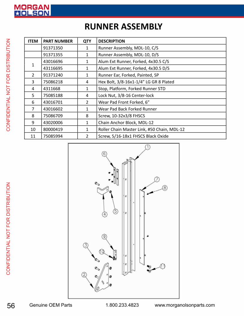
ON ITEM PART NUMBER QTY DESCRIPTION
91371350 1 Runner Assembly, MDL-10, C/S91371355 1 Runner Assembly, MDL-10, D/S
143016696 1 Alum Ext Runner, Forked, 4x30.5 C/S43116695 1 Alum Ext Runner, Forked, 4x30.5 D/S
2 91371240 1 Runner Ear, Forked, Painted, SP3 75086218 4 Hex Bolt, 3/8-16x1-1/4” LG GR 8 Plated4 4311668 1 Stop, Platform, Forked Runner STD5 75085188 4 Lock Nut, 3/8-16 Center-lock6 43016701 2 Wear Pad Front Forked, 6”7 43016602 1 Wear Pad Back Forked Runner8 75086709 8 Screw, 10-32x3/8 FHSCS9 43020006 1 Chain Anchor Block, MDL-12
10 80000419 1 Roller Chain Master Link, #50 Chain, MDL-1211 75085994 2 Screw, 5/16-18x1 FHSCS Black Oxide
RUNNER ASSEMBLY
57USPS 2 Ton Delivery Vehicle 2016 - 2018 Models
CO
NFID
ENTIAL N
OT FO
R D
ISTRIBU
TION
CO
NFID
ENTIAL N
OT FO
R D
ISTRIBU
TION
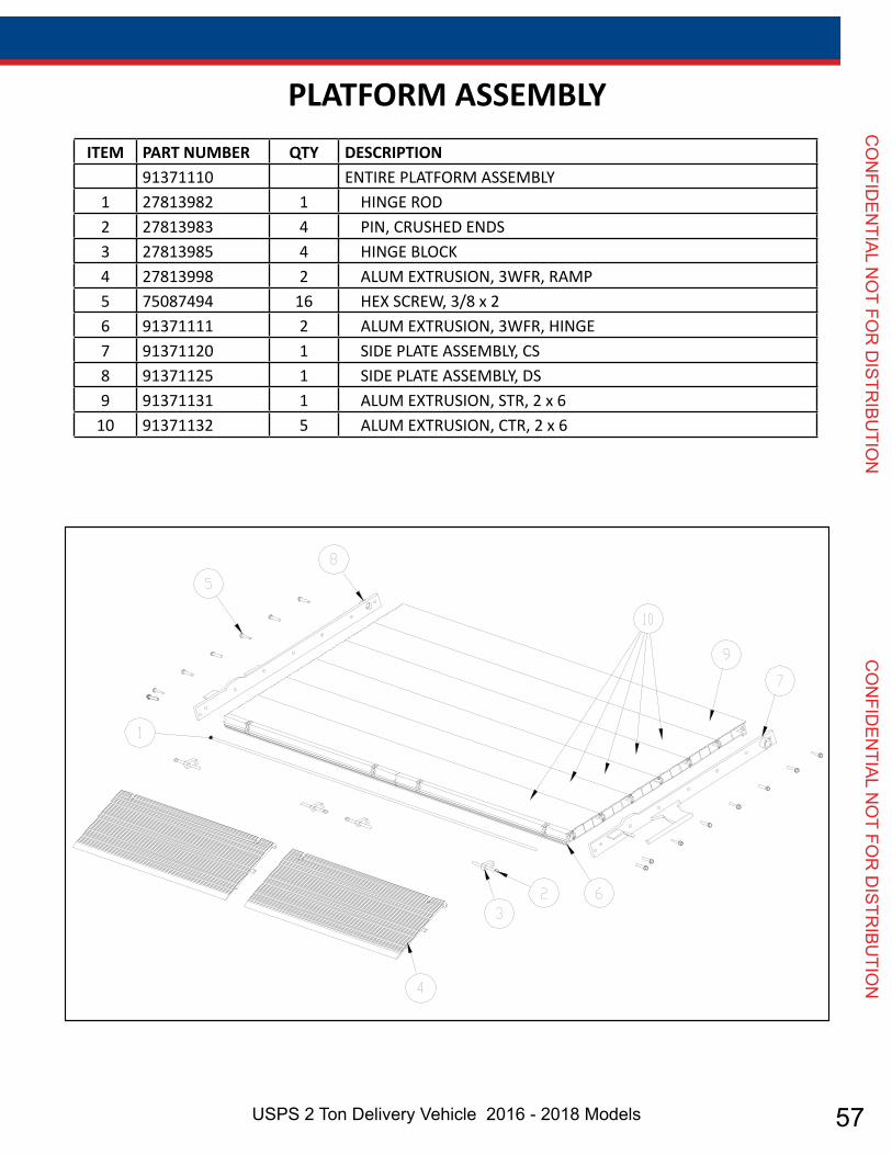
ITEM PART NUMBER QTY DESCRIPTION91371110 ENTIRE PLATFORM ASSEMBLY
1 27813982 1 HINGE ROD2 27813983 4 PIN, CRUSHED ENDS3 27813985 4 HINGE BLOCK4 27813998 2 ALUM EXTRUSION, 3WFR, RAMP5 75087494 16 HEX SCREW, 3/8 x 26 91371111 2 ALUM EXTRUSION, 3WFR, HINGE7 91371120 1 SIDE PLATE ASSEMBLY, CS8 91371125 1 SIDE PLATE ASSEMBLY, DS9 91371131 1 ALUM EXTRUSION, STR, 2 x 6
10 91371132 5 ALUM EXTRUSION, CTR, 2 x 6
PLATFORM ASSEMBLY
58 Genuine OEM Parts 1.800.233.4823 www.morganolsonparts.com
CO
NFI
DEN
TIAL
NO
T FO
R D
ISTR
IBU
TIO
N
C
ON
FID
ENTI
AL N
OT
FOR
DIS
TRIB
UTI
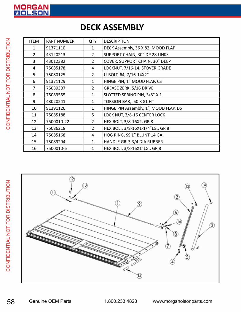
ON ITEM PART NUMBER QTY DESCRIPTION
1 91371110 1 DECK Assembly, 36 X 82, MOOD FLAP2 43120213 2 SUPPORT CHAIN, 30” DP 28 LINKS3 43012382 2 COVER, SUPPORT CHAIN, 30” DEEP4 75085178 4 LOCKNUT, 7/16-14, STOVER GRADE5 75080125 2 U-BOLT, #4, 7/16-14X2”6 91371129 1 HINGE PIN, 1” MOOD FLAP, CS7 75089307 2 GREASE ZERK, 5/16 DRIVE8 75089555 1 SLOTTED SPRING PIN, 3/8” X 19 43020241 1 TORSION BAR, .50 X 81 HT
10 91391126 1 HINGE PIN Assembly, 1”, MOOD FLAP, DS11 75085188 5 LOCK NUT, 3/8-16 CENTER LOCK12 7500010-22 2 HEX BOLT, 3/8-16X2, GR 813 75086218 2 HEX BOLT, 3/8-16X1-1/4”LG., GR 814 75085168 4 HOG RING, SS 1” BLUNT 14 GA15 75089294 1 HANDLE GRIP, 3/4 DIA RUBBER16 7500010-6 1 HEX BOLT, 3/8-16X1”LG., GR 8
DECK ASSEMBLY

59USPS 2 Ton Delivery Vehicle 2016 - 2018 Models
CO
NFID
ENTIAL N
OT FO
R D
ISTRIBU
TION
CO
NFID
ENTIAL N
OT FO
R D
ISTRIBU
TION
ITEM PART NUMBER QTY DESCRIPTION1 90995801 1 Cylinder Assembly Complete, MDL-10A 90995850 1 Cylinder Assembly, MDL-10B 43020013 1 Sprocket, 13T, #50 Chain
80002232 Kit, 13T Sprocket with Pin & HardwareC 43020108 1 Sprocket, 19T, #50 Chain
80002235 Kit 19T Sprocket with Pin & HardwareD 75088064 1 Washer, 5/8” ID x 1-5/16” OD x .095”E 43016859 1 Bearing, Shoe AssemblyF 75086854 1 1/4 – 20x5/8” Type F Plated Round Head Phillips Screw2 75083039 1 Adapter, ¼” NPT Male x #4 JIC Male3 75085188 1 Locknut, 3/8-164 75086218 1 Hex Bolt, 3/8-16x1-1/4”5 43040082 1 Tube, Flexible PVC, 3/16” ID x 60” LG6 7500026-5 1 Elbow, 90 deg Barb, 1/8” NPT7 7010001-15 1 Pressure Comp Valve, 2.5 GPM8 75083355 1 Elbow, #6 Male SAE x ¼ NPTM
CYLINDER ASSEMBLY
60 Genuine OEM Parts 1.800.233.4823 www.morganolsonparts.com
CO
NFI
DEN
TIAL
NO
T FO
R D
ISTR
IBU
TIO
N
C
ON
FID
ENTI
AL N
OT
FOR
DIS
TRIB
UTI
ON
Repairs should be made only by authorized mechanics using WALTCO Replace-ment parts.
When ordering repair or replacement parts, please include all the information asked for below. If this information is not available, a complete written descrip-tion or sketch of the required part will help WALTCO identify and deliver the need-ed part to you. ________________________________________________________________THE FOLLOWING INFORMATION MUST BE INCLUDED: 1. SERIAL NUMBER - [WALTCO lift-gate serial numbers can be found on the Speci-fication Tag attached to the mount frame. (On older units the Specification Tag is located on the side or bottom of the platform.)]
2. MODEL NUMBER - [Or capacity] 3. PLATFORM SIZE _________________________________________________________________
THEN INCLUDE THE FOLLOWING INFORMATION: 4. PART NUMBERS 5. DESCRIPTION 6. QUANTITY REQUIRED ________________________________________________________________
MAIL, E-MAIL OR PHONE YOUR REQUEST TO: Waltco Truck Equipment Co.
285 Northeast Avenue Tallmadge, OH 44278 1-800-411-5685 FAX:
1-800-411-5684 E-MAIL: [email protected]
ALL PARTS ARE F.O.B. FROM THE SHIPPING FACTORY ________________________________________________________________
PLEASE NOTE:
To assure you of continuing and effective quality control, our warranty policy per-mits replacement of hydraulic cylinders, valves and motor pump units when their factory seals are intact. Parts under warranty will be exchanged promptly after careful inspection of the returned assemblies.
61USPS 2 Ton Delivery Vehicle 2016 - 2018 Models
CO
NFID
ENTIAL N
OT FO
R D
ISTRIBU
TION
CO
NFID
ENTIAL N
OT FO
R D
ISTRIBU
TION
Every vehicle that has a WALTCO Lift gate must have legible WARNING AND OPERA-TION DECALS clearly posted on the vehicle and an OWNER’S MANUAL in the vehicle at all times as a guide for proper operation and maintenance.
Additional WARNING DECALS, OPERATION DECALS and OWNER’S MANUALS
Can be obtained from WALTCO LIFT CORP. ____________________
NOTE: When ordering, give model And serial number of the lift-gate.
____________________

62 Genuine OEM Parts 1.800.233.4823 www.morganolsonparts.com
CO
NFI
DEN
TIAL
NO
T FO
R D
ISTR
IBU
TIO
N
C
ON
FID
ENTI
AL N
OT
FOR
DIS
TRIB
UTI
ON
BACK-UP CAMERA & MONITOR
MORGAN OLSON
DRIVER / SERVICE MANUAL5" MONITOR & CAMERA KIT
BACKUP CAMERA SYSTEM
REV. 0, 11/23/2015

63USPS 2 Ton Delivery Vehicle 2016 - 2018 Models
CO
NFID
ENTIAL N
OT FO
R D
ISTRIBU
TION
CO
NFID
ENTIAL N
OT FO
R D
ISTRIBU
TION
5” Color Monitor Backup Camera System User Manual
2
5" COLOR BACKUP CAMERA SYSTEM
TABLE OF CONTENTS 5" Color Backup Camera System. . . . . . . . . . . . . . . . . . . . . . . . . . . . . . . . . . . . 2Components List and Description . . . . . . . . . . . . . . . . . . . . . . . . . . . . . . . . . . . 3Monitor Buttons. . . . . . . . . . . . . . . . . . . . . . . . . . . . . . . . . . . . . . . . . . . . . . . . . . 4Menu Settings . . . . . . . . . . . . . . . . . . . . . . . . . . . . . . . . . . . . . . . . . . . . . . . . . . . 5Wiring Diagram . . . . . . . . . . . . . . . . . . . . . . . . . . . . . . . . . . . . . . . . . . . . . . . . 6 - 7Camera Kit Installation . . . . . . . . . . . . . . . . . . . . . . . . . . . . . . . . . . . . . . . . . . . . . 8Monitor Kit Installation . . . . . . . . . . . . . . . . . . . . . . . . . . . . . . . . . . . . . . . . . . . . . 9System Technical Specifications . . . . . . . . . . . . . . . . . . . . . . . . . . . . . . . . . . . . 10
Rosco Vision Systems introduces a revolutionary new backup camera system for commercial vehicles. The backup camera system utilizes a 5'' inch monitor to display a 16:9 LCD screen when the vehicle shifts into reverse. This monitor allows the driver to see obstructions behind the vehicle for added convenience and safety.
The camera has an advanced CCD image sensor able to process excellent views under dark and light conditions. A 120° diagonal field of vision yields superb coverage behind the vehicle, and complies with the latest U.S. DOT guidelines when installed properly.
DISCLAIMER
• Please read this manual carefully before using the product.• This system is intended as an aid for safe reverse operation. • Drivers must always use extreme caution when operating a vehicle.• Specifications subject to change without prior notice.• Keep all cables AWAY from rotating and electrically noisy components. • Make sure all cables are fastened properly so that you can prevent wire chafing, kinks, cuts, etc...• Always consult your dealer when fitting any electrical or electronic equipment to a vehicle fitted with a CAN-bus or multiple system.
3
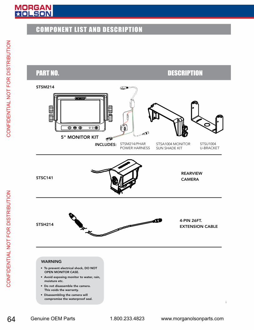
STSC141
STSH214
5" MONITOR KIT
REARVIEW
CAMERA
4-PIN 26FT.
EXTENSION CABLE
STSM214
PART NO. DESCRIPTION
STSA1004 MONITOR SUN SHADE KIT
STSM214/PHAR POWER HARNESS
STSU1004 U-BRACKET
INCLUDES:
COMPONENT LIST AND DESCRIPTION
• To prevent electrical shock, DO NOT OPEN MONITOR CASE.
• Avoid exposing monitor to water, rain, moisture etc.
• Do not disassemble the camera. This voids the warranty.
• Disassembling the camera will compromise the waterproof seal.
WARNING
6162636465666768
BACK-UP CAMERA & MONITOR
64 Genuine OEM Parts 1.800.233.4823 www.morganolsonparts.com
CO
NFI
DEN
TIAL
NO
T FO
R D
ISTR
IBU
TIO
N
C
ON
FID
ENTI
AL N
OT
FOR
DIS
TRIB
UTI
ON
5” Color Monitor Backup Camera System User Manual
2
5" COLOR BACKUP CAMERA SYSTEM
TABLE OF CONTENTS 5" Color Backup Camera System. . . . . . . . . . . . . . . . . . . . . . . . . . . . . . . . . . . . 2Components List and Description . . . . . . . . . . . . . . . . . . . . . . . . . . . . . . . . . . . 3Monitor Buttons. . . . . . . . . . . . . . . . . . . . . . . . . . . . . . . . . . . . . . . . . . . . . . . . . . 4Menu Settings . . . . . . . . . . . . . . . . . . . . . . . . . . . . . . . . . . . . . . . . . . . . . . . . . . . 5Wiring Diagram . . . . . . . . . . . . . . . . . . . . . . . . . . . . . . . . . . . . . . . . . . . . . . . . 6 - 7Camera Kit Installation . . . . . . . . . . . . . . . . . . . . . . . . . . . . . . . . . . . . . . . . . . . . . 8Monitor Kit Installation . . . . . . . . . . . . . . . . . . . . . . . . . . . . . . . . . . . . . . . . . . . . . 9System Technical Specifications . . . . . . . . . . . . . . . . . . . . . . . . . . . . . . . . . . . . 10
Rosco Vision Systems introduces a revolutionary new backup camera system for commercial vehicles. The backup camera system utilizes a 5'' inch monitor to display a 16:9 LCD screen when the vehicle shifts into reverse. This monitor allows the driver to see obstructions behind the vehicle for added convenience and safety.
The camera has an advanced CCD image sensor able to process excellent views under dark and light conditions. A 120° diagonal field of vision yields superb coverage behind the vehicle, and complies with the latest U.S. DOT guidelines when installed properly.
DISCLAIMER
• Please read this manual carefully before using the product.• This system is intended as an aid for safe reverse operation. • Drivers must always use extreme caution when operating a vehicle.• Specifications subject to change without prior notice.• Keep all cables AWAY from rotating and electrically noisy components. • Make sure all cables are fastened properly so that you can prevent wire chafing, kinks, cuts, etc...• Always consult your dealer when fitting any electrical or electronic equipment to a vehicle fitted with a CAN-bus or multiple system.
3
STSC141
STSH214
5" MONITOR KIT
REARVIEW
CAMERA
4-PIN 26FT.
EXTENSION CABLE
STSM214
PART NO. DESCRIPTION
STSA1004 MONITOR SUN SHADE KIT
STSM214/PHAR POWER HARNESS
STSU1004 U-BRACKET
INCLUDES:
COMPONENT LIST AND DESCRIPTION
• To prevent electrical shock, DO NOT OPEN MONITOR CASE.
• Avoid exposing monitor to water, rain, moisture etc.
• Do not disassemble the camera. This voids the warranty.
• Disassembling the camera will compromise the waterproof seal.
WARNING

65USPS 2 Ton Delivery Vehicle 2016 - 2018 Models
CO
NFID
ENTIAL N
OT FO
R D
ISTRIBU
TION
CO
NFID
ENTIAL N
OT FO
R D
ISTRIBU
TION
5” Color Monitor Backup Camera System User Manual
4
MONITOR BUTTONS
i NOTE: The monitor buttons do not function while the vehicle is in reverse. The vehicle must be running and in park/neutral/drive to use the buttons. It is recommended that the buttons are ONLY used in park/neutral.
POWER ON/OFFPowers on the monitor and displays the Camera 1 channel by default.
LIGHT SENSOR (LEFT) POWER LED (RIGHT)Used to adjust screen brightness automatically. Green when ON, Red when OFF
+/- VOLUME/MENU SETTING ADJUST BUTTONSAdjusts the monitor sound volume by default. Adjusts menu settings (e.g. brightness, contrast) according the menu setting selected
MENU SETTING AND PAGE TOGGLEBrings up the monitor settings menu. Press the button again to scroll through the various settings and to access the camera settings menu page (see following page).
5
MENU SETTINGS SCREEN 1:
"MONITOR DIM MODE SETTINGS / MONITOR BRIGHT MODE SETTINGS"
Press the menu button (see preceding page) to access this menu. Press the menu button again to
scroll through the settings:
• BRIGHTNESS Press +/- to adjust the brightness.
• CONTRAST Press +/- to adjust the contrast
• COLOR Press +/- to adjust the color saturation
• TINT Press +/- to adjust the color tint/hue.
• LANGUAGE Press +/- to select the menu language.
• RESET Press either + or - to reset all menu settings to factory default.
MENU SETTINGS SCREEN 2:
"CAMERA SETTINGS"
Keep pressing the menu button to access page 2 of the settings:
• CAM - HORIZONTAL Press +/- to flip the Camera image horizontally.
• CAM - VERTICAL Press +/- to flip the Camera image vertically.
• DIMMING Press +/- to choose between "bright", "dim" and "auto". Choosing
auto will allow the monitor to brighten and dim according to the amount of ambient light in the
cabin.
• SCALE Press +/- to toggle the scale grid ON or OFF. If ON, the scale grid will appear when
the driver shifts the vehicle into reverse in order to assist with distance perception.
• ADJUST SCALE Press + or - to begin adjusting the dimensions of the scale grid. Press - to
switch between the vertical features of the scale and the horizontal "rungs". Press + to change
the width, height, etc of the various features. Press MENU to save the settings and exit. See
figure 1 for an example of the scale grid.
MENU SETTINGS SUMMARY
i NOTE: The monitor buttons do not function while the vehicle is in reverse. The settings can only be adjusted when the vehicle is running in park/neutral/drive. It is recommended that the buttons are ONLY used in park/neutral.
fig 1

66 Genuine OEM Parts 1.800.233.4823 www.morganolsonparts.com
CO
NFI
DEN
TIAL
NO
T FO
R D
ISTR
IBU
TIO
N
C
ON
FID
ENTI
AL N
OT
FOR
DIS
TRIB
UTI
ON
5” Color Monitor Backup Camera System User Manual
4
MONITOR BUTTONS
i NOTE: The monitor buttons do not function while the vehicle is in reverse. The vehicle must be running and in park/neutral/drive to use the buttons. It is recommended that the buttons are ONLY used in park/neutral.
POWER ON/OFFPowers on the monitor and displays the Camera 1 channel by default.
LIGHT SENSOR (LEFT) POWER LED (RIGHT)Used to adjust screen brightness automatically. Green when ON, Red when OFF
+/- VOLUME/MENU SETTING ADJUST BUTTONSAdjusts the monitor sound volume by default. Adjusts menu settings (e.g. brightness, contrast) according the menu setting selected
MENU SETTING AND PAGE TOGGLEBrings up the monitor settings menu. Press the button again to scroll through the various settings and to access the camera settings menu page (see following page).
5
MENU SETTINGS SCREEN 1:
"MONITOR DIM MODE SETTINGS / MONITOR BRIGHT MODE SETTINGS"
Press the menu button (see preceding page) to access this menu. Press the menu button again to
scroll through the settings:
• BRIGHTNESS Press +/- to adjust the brightness.
• CONTRAST Press +/- to adjust the contrast
• COLOR Press +/- to adjust the color saturation
• TINT Press +/- to adjust the color tint/hue.
• LANGUAGE Press +/- to select the menu language.
• RESET Press either + or - to reset all menu settings to factory default.
MENU SETTINGS SCREEN 2:
"CAMERA SETTINGS"
Keep pressing the menu button to access page 2 of the settings:
• CAM - HORIZONTAL Press +/- to flip the Camera image horizontally.
• CAM - VERTICAL Press +/- to flip the Camera image vertically.
• DIMMING Press +/- to choose between "bright", "dim" and "auto". Choosing
auto will allow the monitor to brighten and dim according to the amount of ambient light in the
cabin.
• SCALE Press +/- to toggle the scale grid ON or OFF. If ON, the scale grid will appear when
the driver shifts the vehicle into reverse in order to assist with distance perception.
• ADJUST SCALE Press + or - to begin adjusting the dimensions of the scale grid. Press - to
switch between the vertical features of the scale and the horizontal "rungs". Press + to change
the width, height, etc of the various features. Press MENU to save the settings and exit. See
figure 1 for an example of the scale grid.
MENU SETTINGS SUMMARY
i NOTE: The monitor buttons do not function while the vehicle is in reverse. The settings can only be adjusted when the vehicle is running in park/neutral/drive. It is recommended that the buttons are ONLY used in park/neutral.
fig 1

67USPS 2 Ton Delivery Vehicle 2016 - 2018 Models
CO
NFID
ENTIAL N
OT FO
R D
ISTRIBU
TION
CO
NFID
ENTIAL N
OT FO
R D
ISTRIBU
TION
5” Co
lor M
onito
r Bac
kup
Cam
era
Syst
em U
ser
Man
ual
6
BACK
UP C
AMER
A SY
STEM
Wir
ing
Dia
gra
m
BLA
CK
: Gro
und
RE
D W
IRE
: Ig
nitio
n
GR
EE
N W
IRE
: Rev
erse
CA
ME
RA
C
ON
NE
CTI
ON
STSM
214/
PHA
RM
ON
ITO
R P
OW
ER
HA
RN
ESS
STSU
1004
U-B
RA
CK
ET
4 PI
N C
ON
NE
CTI
ON
13-P
IN D
IN F
EM
ALE
13-P
IN D
IN M
ALE
7
4-PI
N D
IN M
ALE
STSC
141
STSH
214
CA
ME
RA
EX
TEN
SIO
N C
AB
LE
4-PI
N D
IN M
ALE
BACK-UP CAMERA & MONITOR

68 Genuine OEM Parts 1.800.233.4823 www.morganolsonparts.com
CO
NFI
DEN
TIAL
NO
T FO
R D
ISTR
IBU
TIO
N
C
ON
FID
ENTI
AL N
OT
FOR
DIS
TRIB
UTI
ON
5” Color Monitor Backup Camera System User Manual
Camera mounted in suggested location
Mount camera assembly high and centered
Position of camera
Typical monitor image of view from properly installed camera
Obstructions behind truck
Position of camera
CAMERA KIT INSTALL ATION
fig 2
fig 3
fig 4
Vehicle Rear Bumper
CAMERA LOCATION
• Select a high and centered location at the
rear of the vehicle to mount the STSC141
camera. See Figure 2 & 3.
• Mounting the camera near the lower area
of the vehicle (e.g. the bumper) is not
recommended. This reduces the view of the
camera and increases the chance of physical
damage to the camera.
INSTALL MOUNTING BRACKET
• Once the location for the camera is chosen,
use a 3/16” drill bit to drill four holes into
the vehicle using the mounting bracket as a
guide. Be sure to clear any obstacles before
drilling holes.
• Using a 3/4” drill bit, drill a cable hole into
the vehicle using the large center hole in
the mounting bracket as a guide, or choose
a hole location as close as possible to the
camera.
INSTALL CAMERA
• Install the camera mounting bracket. Mount
the camera and sunshade onto the bracket.
Insert the camera cable into the vehicle
through the ¾” hole and install the cable
grommet on the hole.
• Connect the camera cable to the male-
pinned connector of the camera extension
cable (STSH214). Hand-tighten the coupling
ring on the camera cable to ensure a secure
connection, and slide the environmental
boot over the connection.
ROUTE EXTENSION CABLE
• Route the extension cable to the vehicle
cabin at the front of the vehicle. Adhere to
a minimum bend radius of 2”, and keep the
cable away from hot, rotating, or electrically
noisy components.
• Tuck the cable out of sight and secure/clamp
the cable at as many spots as possible to
prevent accidental snagging or damage to
the cable.
9
MONITOR INSTALLATION
• Find a mounting location inside the vehicle cabin that is convenient to the driver (e.g. center of
the dashboard, above the windshield on the ceiling, near the rear view mirror etc).
• Install U-Bracket as desired.
• Using the 4 supplied thumb screws, attach the monitor/sunshade assembly to the U-Bracket
FINALIZING THE INSTALLATION
• Connect the monitor 13-pin connector to the power harness 13-pin connector.
• Connect the camera extension cable from the rear-view camera to the 4-pin connector on the
power harness. Slide the environmental sleeve of the extension over the connection.
• Tuck and fasten/clamp the power harness and extension cable as much as possible into the
vehicle under the dashboard/pillar liners/etc to be out of sight from the driver and passengers.
This reduces the possibility of the cables being hooked or snagged. Keep cables away from HOT,
ROTATING and ELECTRICALLY NOISY components.
• Adhere to a 2-inch bend radius for all cables to prevent damage.
• Connect the 3- Pin connector to vehicle source.
CHECK THE REAR VIEW IMAGE
• Apply the parking brake and start the vehicle. Shift into reverse to ensure the monitor powers on
and displays a rear image. Shift back into park/neutral and power off the vehicle.
• Adjust the angle camera as needed to achieve the desired rear view image. It is highly
• recommended that the image transmitted by the camera shows the rear bumper and area behind
the vehicle. See Figure 4.
MONITOR KIT INSTALL ATION
8
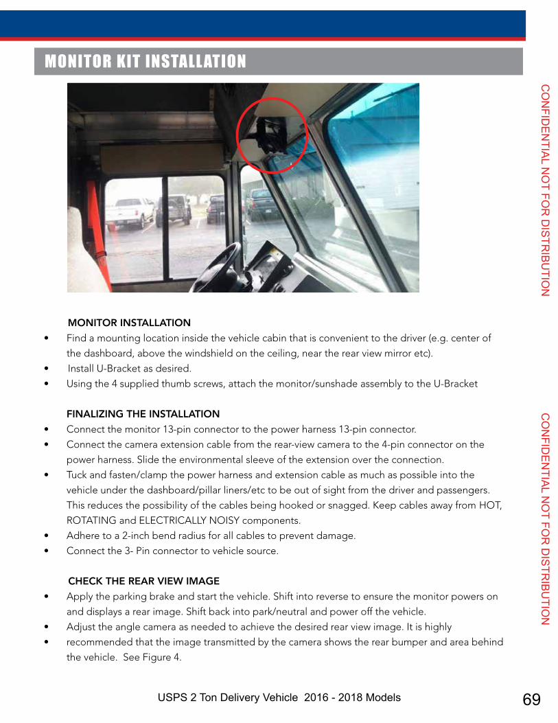
69USPS 2 Ton Delivery Vehicle 2016 - 2018 Models
CO
NFID
ENTIAL N
OT FO
R D
ISTRIBU
TION
CO
NFID
ENTIAL N
OT FO
R D
ISTRIBU
TION
5” Color Monitor Backup Camera System User Manual
Camera mounted in suggested location
Mount camera assembly high and centered
Position of camera
Typical monitor image of view from properly installed camera
Obstructions behind truck
Position of camera
CAMERA KIT INSTALL ATION
fig 2
fig 3
fig 4
Vehicle Rear Bumper
CAMERA LOCATION
• Select a high and centered location at the
rear of the vehicle to mount the STSC141
camera. See Figure 2 & 3.
• Mounting the camera near the lower area
of the vehicle (e.g. the bumper) is not
recommended. This reduces the view of the
camera and increases the chance of physical
damage to the camera.
INSTALL MOUNTING BRACKET
• Once the location for the camera is chosen,
use a 3/16” drill bit to drill four holes into
the vehicle using the mounting bracket as a
guide. Be sure to clear any obstacles before
drilling holes.
• Using a 3/4” drill bit, drill a cable hole into
the vehicle using the large center hole in
the mounting bracket as a guide, or choose
a hole location as close as possible to the
camera.
INSTALL CAMERA
• Install the camera mounting bracket. Mount
the camera and sunshade onto the bracket.
Insert the camera cable into the vehicle
through the ¾” hole and install the cable
grommet on the hole.
• Connect the camera cable to the male-
pinned connector of the camera extension
cable (STSH214). Hand-tighten the coupling
ring on the camera cable to ensure a secure
connection, and slide the environmental
boot over the connection.
ROUTE EXTENSION CABLE
• Route the extension cable to the vehicle
cabin at the front of the vehicle. Adhere to
a minimum bend radius of 2”, and keep the
cable away from hot, rotating, or electrically
noisy components.
• Tuck the cable out of sight and secure/clamp
the cable at as many spots as possible to
prevent accidental snagging or damage to
the cable.
9
MONITOR INSTALLATION
• Find a mounting location inside the vehicle cabin that is convenient to the driver (e.g. center of
the dashboard, above the windshield on the ceiling, near the rear view mirror etc).
• Install U-Bracket as desired.
• Using the 4 supplied thumb screws, attach the monitor/sunshade assembly to the U-Bracket
FINALIZING THE INSTALLATION
• Connect the monitor 13-pin connector to the power harness 13-pin connector.
• Connect the camera extension cable from the rear-view camera to the 4-pin connector on the
power harness. Slide the environmental sleeve of the extension over the connection.
• Tuck and fasten/clamp the power harness and extension cable as much as possible into the
vehicle under the dashboard/pillar liners/etc to be out of sight from the driver and passengers.
This reduces the possibility of the cables being hooked or snagged. Keep cables away from HOT,
ROTATING and ELECTRICALLY NOISY components.
• Adhere to a 2-inch bend radius for all cables to prevent damage.
• Connect the 3- Pin connector to vehicle source.
CHECK THE REAR VIEW IMAGE
• Apply the parking brake and start the vehicle. Shift into reverse to ensure the monitor powers on
and displays a rear image. Shift back into park/neutral and power off the vehicle.
• Adjust the angle camera as needed to achieve the desired rear view image. It is highly
• recommended that the image transmitted by the camera shows the rear bumper and area behind
the vehicle. See Figure 4.
MONITOR KIT INSTALL ATION
8
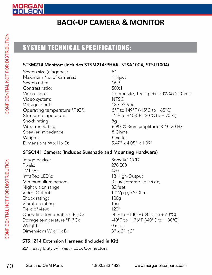
70 Genuine OEM Parts 1.800.233.4823 www.morganolsonparts.com
CO
NFI
DEN
TIAL
NO
T FO
R D
ISTR
IBU
TIO
N
C
ON
FID
ENTI
AL N
OT
FOR
DIS
TRIB
UTI
ON
5” Color Monitor Backup Camera System User Manual
10
Image device: Sony ¼" CCDPixels: 270,000TV lines: 420 InfraRed LED's: 18 High-OutputMinimum illumination: 0 Lux (infrared LED's on)Night vision range: 30 feetVideo Output: 1.0 Vp-p, 75 OhmShock rating: 100gVibration rating: 15gField of view: 120°Operating temperature °F (°C): -4°F to +140°F (-20°C to + 60°C)Storage temperature °F (°C): -40°F to +176°F (-40°C to + 80°C)Weight: 0.6 lbs.Dimensions W x H x D: 3" x 2" x 2"
SYSTEM TECHNICAL SPECIFICATIONS:
STSM214 Monitor: (Includes STSM214/PHAR, STSA1004, STSU1004)
STSC141 Camera: (Includes Sunshade and Mounting Hardware)
26’ Heavy Duty w/ Twist - Lock Connectors
STSH214 Extension Harness: (Included in Kit)
Screen size (diagonal): 5"Maximum No. of cameras: 1 InputScreen ratio: 16:9Contrast ratio: 500:1Video Input: Composite, 1 V p-p +/- 20% @75 OhmsVideo system: NTSCVoltage input: 12 ~32 VdcOperating temperature °F (C°): 5°F to 149°F (-15°C to +65°C)Storage temperature: -4°F to +158°F (-20°C to + 70°C)Shock rating: 8gVibration Rating: 6.9G @ 3mm amplitude & 10-30 HzSpeaker Impedance: 8 OhmsWeight: 0.66 lbsDimensions W x H x D: 5.47" x 4.05" x 1.09"
11
NOTES
BACK-UP CAMERA & MONITOR

71USPS 2 Ton Delivery Vehicle 2016 - 2018 Models
CO
NFID
ENTIAL N
OT FO
R D
ISTRIBU
TION
CO
NFID
ENTIAL N
OT FO
R D
ISTRIBU
TION
MORGAN OLSON R E A R V I E W M I R R O R S Y S T E M
6647RSSPH6647LSSPH
DRIVER / SERVICE MANUALREV 0 - 11/19/2015
REAR VIEW MIRROR SYSTEM

72 Genuine OEM Parts 1.800.233.4823 www.morganolsonparts.com
CO
NFI
DEN
TIAL
NO
T FO
R D
ISTR
IBU
TIO
N
C
ON
FID
ENTI
AL N
OT
FOR
DIS
TRIB
UTI
ON
MORGAN OLSON Rearview Mirror System - DRIVER MANUAL 6647RSSPH / 6647LSSPH
2 3
Heated Flat Mirror Head
(1) Exterior left hand rear view mirror assembly Including:
• (1) Heated flat head• (1) Heated convex mirror head
Heated Convex Mirror Head
D r i v e r ' s S i d e M i r r o r A s s e m b l y
(1) Exterior right hand rear view mirror assembly Including:
• (1) Heated flat head• (1) Heated convex mirror head
P a s s e n g e r ' s S i d e M i r r o r A s s e m b l y
Heated Flat Mirror Head
Heated Convex Mirror Head
COMPONENTS LIST AND DESCRIPTIONS
TABLE OF CONTENTS Components List and Description . . . . . . . . . . . . . . . . . . . . . . . . . . . . . . . . . . . . . . . . 2
Mirror System Adjustment . . . . . . . . . . . . . . . . . . . . . . . . . . . . . . . . . . . . . . . . . . . . . . . 3
Operating Heated Mirrors . . . . . . . . . . . . . . . . . . . . . . . . . . . . . . . . . . . . . . . . . . . . . . . . 4
Mirror Storage . . . . . . . . . . . . . . . . . . . . . . . . . . . . . . . . . . . . . . . . . . . . . . . . . . . . . . . 4
Wear Component Replacement . . . . . . . . . . . . . . . . . . . . . . . . . . . . . . . . . . . . . . . . . . . . . . 5
Heated Mirror Replacement . . . . . . . . . . . . . . . . . . . . . . . . . . . . . . . . . . . . . . . . . . . . . 6-7
MIRROR SYSTEM ADJUSTMENT
According to FEDERAL MOTOR VEHICLE SAFETY STANDARDS No.111, rearview mirrors must be adjusted “…so as to provide the driver a view to the rear along both sides of the vehicle and shall be adjusted both in the horizontal and vertical directions to view the rearward scene.” Adjust the lookdown mirror head so as to provide the driver a view in front of the bumper and to the right of the front-right wheel.
Each rearview mirror head is 4-way hand adjustable (up/down/left/right).
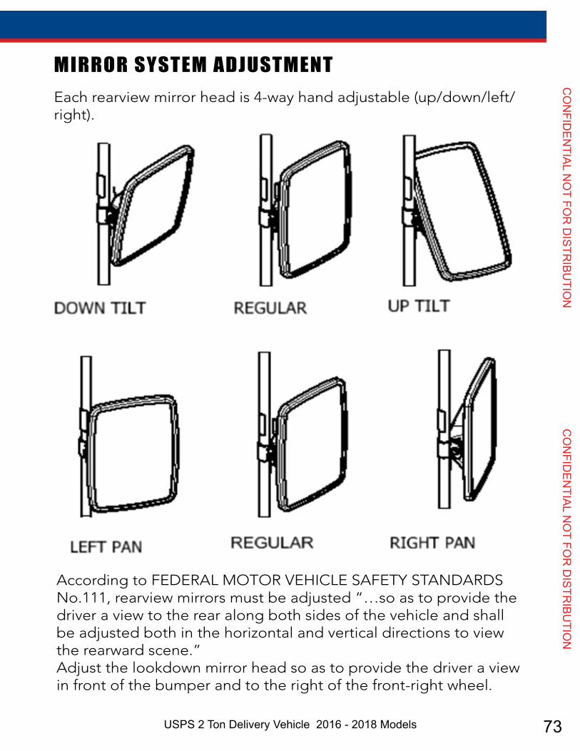
73USPS 2 Ton Delivery Vehicle 2016 - 2018 Models
CO
NFID
ENTIAL N
OT FO
R D
ISTRIBU
TION
CO
NFID
ENTIAL N
OT FO
R D
ISTRIBU
TION
MORGAN OLSON Rearview Mirror System - DRIVER MANUAL 6647RSSPH / 6647LSSPH
2 3
Heated Flat Mirror Head
(1) Exterior left hand rear view mirror assembly Including:
• (1) Heated flat head• (1) Heated convex mirror head
Heated Convex Mirror Head
D r i v e r ' s S i d e M i r r o r A s s e m b l y
(1) Exterior right hand rear view mirror assembly Including:
• (1) Heated flat head• (1) Heated convex mirror head
P a s s e n g e r ' s S i d e M i r r o r A s s e m b l y
Heated Flat Mirror Head
Heated Convex Mirror Head
COMPONENTS LIST AND DESCRIPTIONS
TABLE OF CONTENTS Components List and Description . . . . . . . . . . . . . . . . . . . . . . . . . . . . . . . . . . . . . . . . 2
Mirror System Adjustment . . . . . . . . . . . . . . . . . . . . . . . . . . . . . . . . . . . . . . . . . . . . . . . 3
Operating Heated Mirrors . . . . . . . . . . . . . . . . . . . . . . . . . . . . . . . . . . . . . . . . . . . . . . . . 4
Mirror Storage . . . . . . . . . . . . . . . . . . . . . . . . . . . . . . . . . . . . . . . . . . . . . . . . . . . . . . . 4
Wear Component Replacement . . . . . . . . . . . . . . . . . . . . . . . . . . . . . . . . . . . . . . . . . . . . . . 5
Heated Mirror Replacement . . . . . . . . . . . . . . . . . . . . . . . . . . . . . . . . . . . . . . . . . . . . . 6-7
MIRROR SYSTEM ADJUSTMENT
According to FEDERAL MOTOR VEHICLE SAFETY STANDARDS No.111, rearview mirrors must be adjusted “…so as to provide the driver a view to the rear along both sides of the vehicle and shall be adjusted both in the horizontal and vertical directions to view the rearward scene.” Adjust the lookdown mirror head so as to provide the driver a view in front of the bumper and to the right of the front-right wheel.
Each rearview mirror head is 4-way hand adjustable (up/down/left/right).

74 Genuine OEM Parts 1.800.233.4823 www.morganolsonparts.com
CO
NFI
DEN
TIAL
NO
T FO
R D
ISTR
IBU
TIO
N
C
ON
FID
ENTI
AL N
OT
FOR
DIS
TRIB
UTI
ON
MORGAN OLSON Rearview Mirror System - DRIVER MANUAL 6647RSSPH / 6647LSSPH
OPERATING HEATED MIRRORSEach rear view mirror head has a heating element behind the glass to assist with defogging / defrosting. When needed, simply depress the heater control switch. A small light (LED) on the bottom will confirm that heaters are on. Heaters will automatically turn off after 12 minutes.
MIRROR STORAGETo collapse the mirror assemblies for vehicle storage, transport, or parking in areas where the width profile of the truck should be minimized, the driver should hold the vertical mirror arm between the mirror heads, and rotate it forward or rearward to preference.
CAUTION - be careful not to forcefully push the mirror assembly into the vehicle side or window so as to cause damage or bodily harm.
During the life of the mirror assembly, the upper and lower locking mechanism components may wear out and need to be replaced. This is normal. See diagram below for details -- use wrenches compatible with 5/16” fasteners and apply tightening torque accordingly. Wear components are the same between LH and RH assemblies, except upper mounting bases.
WEAR COMPONENT REPL ACEMENT
4 5

75USPS 2 Ton Delivery Vehicle 2016 - 2018 Models
CO
NFID
ENTIAL N
OT FO
R D
ISTRIBU
TION
CO
NFID
ENTIAL N
OT FO
R D
ISTRIBU
TION
MORGAN OLSON Rearview Mirror System - DRIVER MANUAL 6647RSSPH / 6647LSSPH
OPERATING HEATED MIRRORSEach rear view mirror head has a heating element behind the glass to assist with defogging / defrosting. When needed, simply depress the heater control switch. A small light (LED) on the bottom will confirm that heaters are on. Heaters will automatically turn off after 12 minutes.
MIRROR STORAGETo collapse the mirror assemblies for vehicle storage, transport, or parking in areas where the width profile of the truck should be minimized, the driver should hold the vertical mirror arm between the mirror heads, and rotate it forward or rearward to preference.
CAUTION - be careful not to forcefully push the mirror assembly into the vehicle side or window so as to cause damage or bodily harm.
During the life of the mirror assembly, the upper and lower locking mechanism components may wear out and need to be replaced. This is normal. See diagram below for details -- use wrenches compatible with 5/16” fasteners and apply tightening torque accordingly. Wear components are the same between LH and RH assemblies, except upper mounting bases.
WEAR COMPONENT REPL ACEMENT
4 5

76 Genuine OEM Parts 1.800.233.4823 www.morganolsonparts.com
CO
NFI
DEN
TIAL
NO
T FO
R D
ISTR
IBU
TIO
N
C
ON
FID
ENTI
AL N
OT
FOR
DIS
TRIB
UTI
ON

77USPS 2 Ton Delivery Vehicle 2016 - 2018 Models
CO
NFID
ENTIAL N
OT FO
R D
ISTRIBU
TION
CO
NFID
ENTIAL N
OT FO
R D
ISTRIBU
TION
MORGAN OLSON Rearview Mirror System - SERVICE MANUAL 6647RSSPH / 6647LSSPH
HEATED MIRROR REPL ACEMENTReplace mirror heads when glass is broken, or when the heating element fails to heat the glass. The following steps apply to either a flat or convex mirror head.
Step 1: Pull out black grommet and cable from oval hole, and expose butt spliced connections. Cut wires as shown. Step 2: Remove 5/16-18” hex head screw and lock washer to disassemble defective mirror head. Remove defective mirror head. Ensure that remaining mirror head harness stays in place.Step 3: Loosely attach new mirror head to the clamp. Run heater harness through the oval into the tubular arm until the end reaches the other oval hole.Step 4: Using provided butt splices, crimp black and white wires accordingly. Push wires inside the tubing towards the flattened end and re-attach oval grommet.
Step 5: Tighten mirror head hardware on the clamp to 200 in. lbs. be sure that clamp location on the tube is correct per below diagram:
6 7
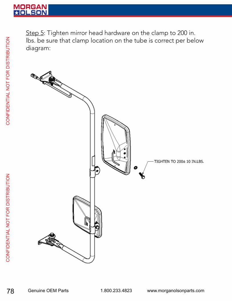
78 Genuine OEM Parts 1.800.233.4823 www.morganolsonparts.com
CO
NFI
DEN
TIAL
NO
T FO
R D
ISTR
IBU
TIO
N
C
ON
FID
ENTI
AL N
OT
FOR
DIS
TRIB
UTI
ON
MORGAN OLSON Rearview Mirror System - SERVICE MANUAL 6647RSSPH / 6647LSSPH
HEATED MIRROR REPL ACEMENTReplace mirror heads when glass is broken, or when the heating element fails to heat the glass. The following steps apply to either a flat or convex mirror head.
Step 1: Pull out black grommet and cable from oval hole, and expose butt spliced connections. Cut wires as shown. Step 2: Remove 5/16-18” hex head screw and lock washer to disassemble defective mirror head. Remove defective mirror head. Ensure that remaining mirror head harness stays in place.Step 3: Loosely attach new mirror head to the clamp. Run heater harness through the oval into the tubular arm until the end reaches the other oval hole.Step 4: Using provided butt splices, crimp black and white wires accordingly. Push wires inside the tubing towards the flattened end and re-attach oval grommet.
Step 5: Tighten mirror head hardware on the clamp to 200 in. lbs. be sure that clamp location on the tube is correct per below diagram:
6 7

79USPS 2 Ton Delivery Vehicle 2016 - 2018 Models
CO
NFID
ENTIAL N
OT FO
R D
ISTRIBU
TION
CO
NFID
ENTIAL N
OT FO
R D
ISTRIBU
TION
Morgan Olson Operator & Service Manualfor Keyless Entry Controller Diagnostics
PN 46029040
NST12302-3_A.ai 2015-10-07
1801 South Nottawa Road Sturgis, MI 49091
(800) 233-4823
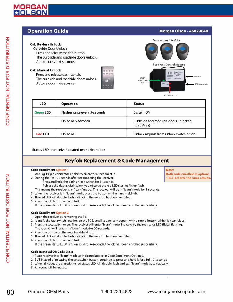
80 Genuine OEM Parts 1.800.233.4823 www.morganolsonparts.com
CO
NFI
DEN
TIAL
NO
T FO
R D
ISTR
IBU
TIO
N
C
ON
FID
ENTI
AL N
OT
FOR
DIS
TRIB
UTI
ON
Receiver / Control Module
AntennaGREEN
Power/StatusLED
RED “Learn” LED
10 Pin Connector
Transmitters / Keyfobs
Code Enrollment Option 11. Unplug 10-pin connector on the receiver, then reconnect it.2. During the 1st 10-seconds after reconnecting the receiver, Press and hold the dash unlock switch for 5-seconds. Release the dash switch when you observe the red LED start to �icker �ash. This means the receiver is in “learn” mode. The receiver will be in “learn” mode for 5-seconds.3. When the receiver is in “learn” mode, press the button on the hand-held fob.4. The red LED will double �ash indicating the new fob has been enrolled.5. Press the fob button once to test. If the green status LED turns on solid for 6-seconds, the fob has been enrolled successfully.
NST12302-3_A.ai 2015-10-07 Pg -2-
Morgan Olson - 46029040Operation Guide
Code Enrollment Option 21. Open the receiver by removing the lid.2. Identify the tact switch location on the PCB, small square component with a round button, which is near relays.3. Press the tact switch once. The receiver will enter “learn” mode, indicatd by the red status LED �icker �ashing. The receiver will remain in “learn” mode for 20-seconds.4. Press the button on the new hand-held fob.5. The red LED will double �ash indicating the new fob has been enrolled.6. Press the fob button once to test. If the green status LED turns on solid for 6-seconds, the fob has been enrolled successfully.
Code Removal OR Code Erase1. Place receiver into “learn” mode as indicated above in Code Enrollment Option 2.2. BUT instead of releasing the tact switch button, continue to press and hold it for a full 10-seconds.3. When all codes are erased, the red status LED will double �ash and exit “learn” mode automatically.5. All codes will be erased.
Cab Keyless Unlock Curbside Door Unlock Press and release the fob button. The curbside and roadside doors unlock. Auto relocks in 6-seconds.
Cab Manual Unlock Press and release dash switch. The curbside and roadside doors unlock. Auto relocks in 6-seconds.
LED
Green LED
Red LED
Operation
Flashes once every 5-seconds
ON solid 6-seconds
ON solid
Status
System ON
Curbside and roadside doors unlocked (Cab Area)
Unlock request from unlock switch or fob
Status LED on receiver located over driver door.
Keyfob Replacement & Code Management
Note:Both code enrollment options 1 & 2 acheive the same results.

81USPS 2 Ton Delivery Vehicle 2016 - 2018 Models
CO
NFID
ENTIAL N
OT FO
R D
ISTRIBU
TION
CO
NFID
ENTIAL N
OT FO
R D
ISTRIBU
TION
Transmitter - FOB46029111
Receiver46029040
Morgan Olson - 46029040Trouble Shooting Guide
NST12302-3_A.ai 2015-10-07 Pg -3-
Status & Diagnostic LEDsGreen LEDPower Reset Both Red & Green LED ON for 10-seconds solid.Quick Learn Both Red & Green LEDs will turn OFF then Red LED will �icker �ash for 5-seconds. If a new fob is enrolled, it will double �ash and turn OFF.Power Green status LED �ashes once every 5-seconds.Curbside and Roadside Doors Green status LED turns on solid for 6-seconds.
Red LEDInput signals When any input signal is detected (from fob or switch), the red LED will remain ON solid as long as the signal is present.“Learn” Mode Red LED �icker �ashes in “learn” mode and double �ashes when a new fob is enrolled or “learn” mode exits.
Error Code for continuous inputs signal from A1 dash switch or RF fob. A1 dash switch - single �ash approximately once every 2- 3 seconds. RF fob enrolled - triple �ash approximately once every 2 - 3 seconds.
100 Feet TypicalUp to 300 Feet
OUTPUT 4 Relays, Positive, 5AINPUT 2 Inputs, +12V
FREQUENCY 433 MHzRolling CodesSecure Encryption
VOLTAGE 12VDC5 Amps Max per Output, (Relay)10 Amp, Input (Max)
ANTENNA, OPTIONAL Fixed, Standard (shown)Coin Style, Lithium, CR2032100,000 1-second pulses10 year shelf life
CURRENT
BATTERY
System Speci�cationsP/N#46029040 / Model #P1550-R
RANGE
CODES
Part Numbers
OPERATIONPress ONCE to unlock
curbside & roadsidedoors. Doors auto-relock
in 6-sec.
F15A
CurbsideSol
46029042
RoadsideSol
46029041
GREEN / BLACK +12V
PINK / BLACK +12V
POWER+12VDC
POWER
INPUT
12345
109876
THREE FOBs PER KIT
ANTENNA
NC
NC
UNLOCK SWITCH
GROUND+12V POWER
CURBSIDE SOL
EMPTY
EMPTYROADSIDE SOL
1 2 3 4 5109876
VIEW CONNECTOR +12V POWER
EMPTY
+12V POWER
DASH UNLOCKSWITCHRECEIVER 46029040
WHITE
CHASSISGROUND
RED
NC
GREEN / YELLOW REDRED
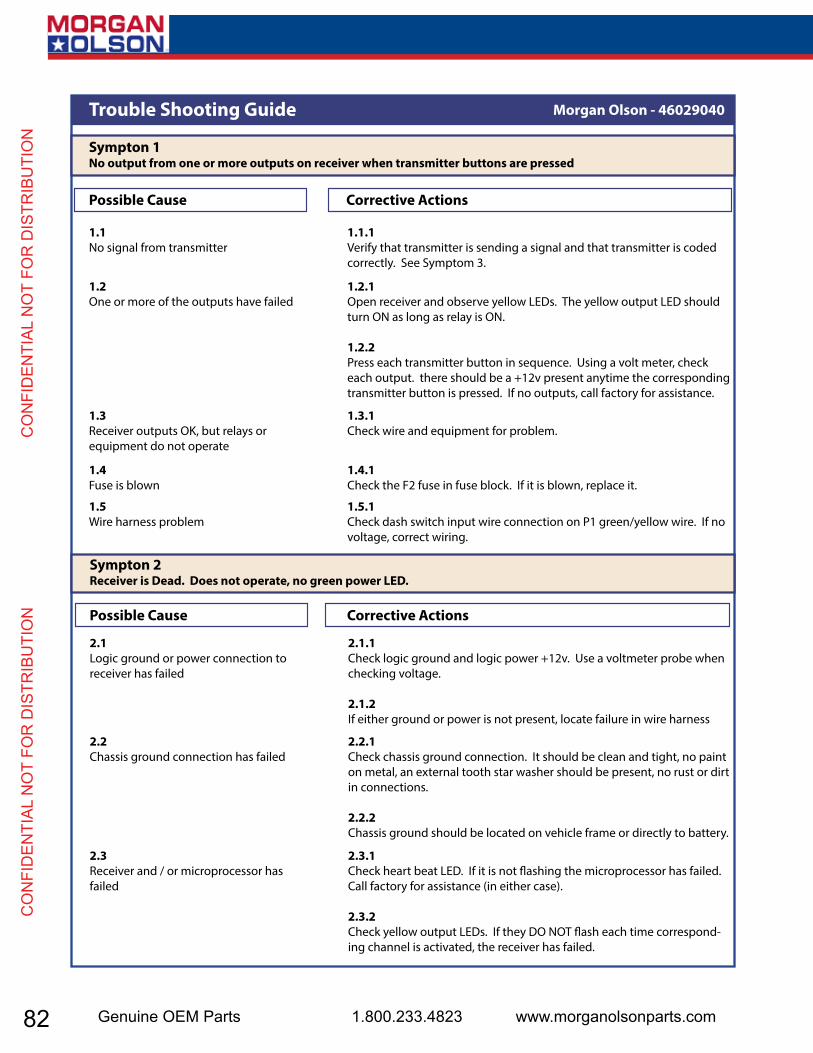
82 Genuine OEM Parts 1.800.233.4823 www.morganolsonparts.com
CO
NFI
DEN
TIAL
NO
T FO
R D
ISTR
IBU
TIO
N
C
ON
FID
ENTI
AL N
OT
FOR
DIS
TRIB
UTI
ON
1.1.1Verify that transmitter is sending a signal and that transmitter is coded correctly. See Symptom 3.
1.1No signal from transmitter
Morgan Olson - 46029040Trouble Shooting Guide
Sympton 1No output from one or more outputs on receiver when transmitter buttons are pressed
Possible Cause Corrective Actions
NST12302-3_A.ai 2015-10-07 Pg -4-
1.2.1Open receiver and observe yellow LEDs. The yellow output LED should turn ON as long as relay is ON.
1.2.2Press each transmitter button in sequence. Using a volt meter, check each output. there should be a +12v present anytime the corresponding transmitter button is pressed. If no outputs, call factory for assistance.
1.2One or more of the outputs have failed
1.3.1Check wire and equipment for problem.
1.3Receiver outputs OK, but relays or equipment do not operate
1.4.1Check the F2 fuse in fuse block. If it is blown, replace it.
1.4Fuse is blown
1.5.1Check dash switch input wire connection on P1 green/yellow wire. If no voltage, correct wiring.
1.5Wire harness problem
2.1.1Check logic ground and logic power +12v. Use a voltmeter probe when checking voltage.
2.1.2If either ground or power is not present, locate failure in wire harness
2.1Logic ground or power connection to receiver has failed
Sympton 2Receiver is Dead. Does not operate, no green power LED.
Possible Cause Corrective Actions
2.2.1Check chassis ground connection. It should be clean and tight, no paint on metal, an external tooth star washer should be present, no rust or dirt in connections.
2.2.2Chassis ground should be located on vehicle frame or directly to battery.
2.2Chassis ground connection has failed
2.3.1Check heart beat LED. If it is not �ashing the microprocessor has failed. Call factory for assistance (in either case).
2.3.2Check yellow output LEDs. If they DO NOT �ash each time correspond-ing channel is activated, the receiver has failed.
2.3Receiver and / or microprocessor has failed
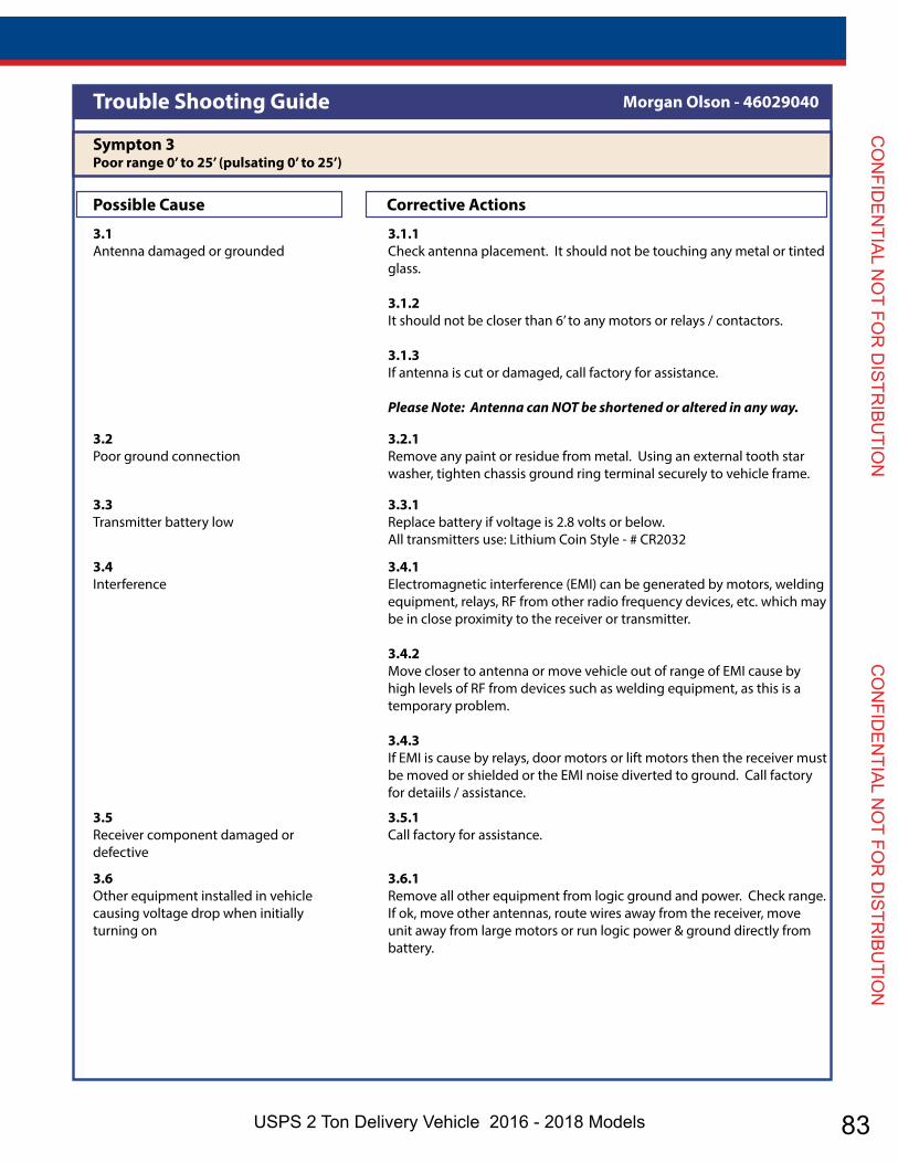
83USPS 2 Ton Delivery Vehicle 2016 - 2018 Models
CO
NFID
ENTIAL N
OT FO
R D
ISTRIBU
TION
CO
NFID
ENTIAL N
OT FO
R D
ISTRIBU
TION
3.1.1Check antenna placement. It should not be touching any metal or tinted glass.
3.1.2It should not be closer than 6’ to any motors or relays / contactors.
3.1.3If antenna is cut or damaged, call factory for assistance.
Please Note: Antenna can NOT be shortened or altered in any way.
3.1Antenna damaged or grounded
Morgan Olson - 46029040Trouble Shooting Guide
Sympton 3Poor range 0’ to 25’ (pulsating 0’ to 25’)
Possible Cause Corrective Actions
NST12302-3_A.ai 2015-10-07 Pg -5-
3.2.1Remove any paint or residue from metal. Using an external tooth star washer, tighten chassis ground ring terminal securely to vehicle frame.
3.2Poor ground connection
3.3.1Replace battery if voltage is 2.8 volts or below. All transmitters use: Lithium Coin Style - # CR2032
3.3Transmitter battery low
3.4.1Electromagnetic interference (EMI) can be generated by motors, welding equipment, relays, RF from other radio frequency devices, etc. which may be in close proximity to the receiver or transmitter.
3.4.2Move closer to antenna or move vehicle out of range of EMI cause by high levels of RF from devices such as welding equipment, as this is a temporary problem.
3.4.3If EMI is cause by relays, door motors or lift motors then the receiver must be moved or shielded or the EMI noise diverted to ground. Call factory for detaiils / assistance.
3.4Interference
3.5.1Call factory for assistance.
3.5Receiver component damaged or defective
3.6.1Remove all other equipment from logic ground and power. Check range. If ok, move other antennas, route wires away from the receiver, move unit away from large motors or run logic power & ground directly from battery.
3.6Other equipment installed in vehicle causing voltage drop when initially turning on
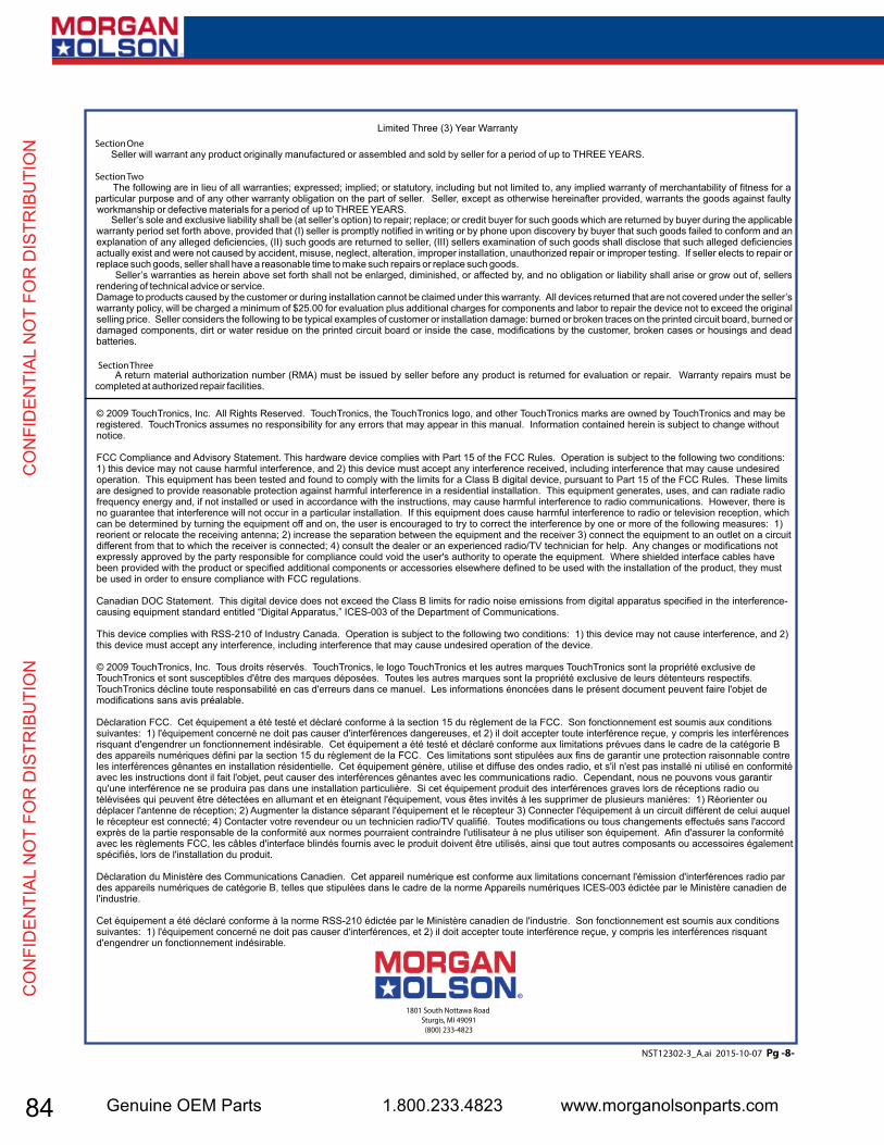
84 Genuine OEM Parts 1.800.233.4823 www.morganolsonparts.com
CO
NFI
DEN
TIAL
NO
T FO
R D
ISTR
IBU
TIO
N
C
ON
FID
ENTI
AL N
OT
FOR
DIS
TRIB
UTI
ON
Limited Three (3) Year Warranty
© 2009 TouchTronics, Inc. All Rights Reserved. TouchTronics, the TouchTronics logo, and other TouchTronics marks are owned by TouchTronics and may be registered. TouchTronics assumes no responsibility for any errors that may appear in this manual. Information contained herein is subject to change without notice.
FCC Compliance and Advisory Statement. This hardware device complies with Part 15 of the FCC Rules. Operation is subject to the following two conditions: 1) this device may not cause harmful interference, and 2) this device must accept any interference received, including interference that may cause undesired operation. This equipment has been tested and found to comply with the limits for a Class B digital device, pursuant to Part 15 of the FCC Rules. These limits are designed to provide reasonable protection against harmful interference in a residential installation. This equipment generates, uses, and can radiate radio frequency energy and, if not installed or used in accordance with the instructions, may cause harmful interference to radio communications. However, there is no guarantee that interference will not occur in a particular installation. If this equipment does cause harmful interference to radio or television reception, which can be determined by turning the equipment off and on, the user is encouraged to try to correct the interference by one or more of the following measures: 1) reorient or relocate the receiving antenna; 2) increase the separation between the equipment and the receiver 3) connect the equipment to an outlet on a circuit different from that to which the receiver is connected; 4) consult the dealer or an experienced radio/TV technician for help. Any changes or modifications not expressly approved by the party responsible for compliance could void the user's authority to operate the equipment. Where shielded interface cables have been provided with the product or specified additional components or accessories elsewhere defined to be used with the installation of the product, they must be used in order to ensure compliance with FCC regulations.
Canadian DOC Statement. This digital device does not exceed the Class B limits for radio noise emissions from digital apparatus specified in the interference-causing equipment standard entitled “Digital Apparatus,” ICES-003 of the Department of Communications.
This device complies with RSS-210 of Industry Canada. Operation is subject to the following two conditions: 1) this device may not cause interference, and 2) this device must accept any interference, including interference that may cause undesired operation of the device.
© 2009 TouchTronics, Inc. Tous droits réservés. TouchTronics, le logo TouchTronics et les autres marques TouchTronics sont la propriété exclusive de TouchTronics et sont susceptibles d'être des marques déposées. Toutes les autres marques sont la propriété exclusive de leurs détenteurs respectifs. TouchTronics décline toute responsabilité en cas d'erreurs dans ce manuel. Les informations énoncées dans le présent document peuvent faire l'objet de modifications sans avis préalable.
Déclaration FCC. Cet équipement a été testé et déclaré conforme à la section 15 du règlement de la FCC. Son fonctionnement est soumis aux conditions suivantes: 1) l'équipement concerné ne doit pas causer d'interférences dangereuses, et 2) il doit accepter toute interférence reçue, y compris les interférences risquant d'engendrer un fonctionnement indésirable. Cet équipement a été testé et déclaré conforme aux limitations prévues dans le cadre de la catégorie B des appareils numériques défini par la section 15 du règlement de la FCC. Ces limitations sont stipulées aux fins de garantir une protection raisonnable contre les interférences gênantes en installation résidentielle. Cet équipement génère, utilise et diffuse des ondes radio, et s'il n'est pas installé ni utilisé en conformité avec les instructions dont il fait l'objet, peut causer des interférences gênantes avec les communications radio. Cependant, nous ne pouvons vous garantir qu'une interférence ne se produira pas dans une installation particulière. Si cet équipement produit des interférences graves lors de réceptions radio ou télévisées qui peuvent être détectées en allumant et en éteignant l'équipement, vous êtes invités à les supprimer de plusieurs manières: 1) Réorienter ou déplacer l'antenne de réception; 2) Augmenter la distance séparant l'équipement et le récepteur 3) Connecter l'équipement à un circuit différent de celui auquel le récepteur est connecté; 4) Contacter votre revendeur ou un technicien radio/TV qualifié. Toutes modifications ou tous changements effectués sans l'accord exprès de la partie responsable de la conformité aux normes pourraient contraindre l'utilisateur à ne plus utiliser son équipement. Afin d'assurer la conformité avec les règlements FCC, les câbles d'interface blindés fournis avec le produit doivent être utilisés, ainsi que tout autres composants ou accessoires également spécifiés, lors de l'installation du produit.
Déclaration du Ministère des Communications Canadien. Cet appareil numérique est conforme aux limitations concernant l'émission d'interférences radio par des appareils numériques de catégorie B, telles que stipulées dans le cadre de la norme Appareils numériques ICES-003 édictée par le Ministère canadien de l'industrie.
Cet équipement a été déclaré conforme à la norme RSS-210 édictée par le Ministère canadien de l'industrie. Son fonctionnement est soumis aux conditions suivantes: 1) l'équipement concerné ne doit pas causer d'interférences, et 2) il doit accepter toute interférence reçue, y compris les interférences risquant d'engendrer un fonctionnement indésirable.
Section One Seller will warrant any product originally manufactured or assembled and sold by seller for a period of up to THREE YEARS.
Section Two The following are in lieu of all warranties; expressed; implied; or statutory, including but not limited to, any implied warranty of merchantability of fitness for a particular purpose and of any other warranty obligation on the part of seller. Seller, except as otherwise hereinafter provided, warrants the goods against faulty workmanship or defective materials for a period of up to THREE YEARS. Seller’s sole and exclusive liability shall be (at seller’s option) to repair; replace; or credit buyer for such goods which are returned by buyer during the applicable warranty period set forth above, provided that (I) seller is promptly notified in writing or by phone upon discovery by buyer that such goods failed to conform and an explanation of any alleged deficiencies, (II) such goods are returned to seller, (III) sellers examination of such goods shall disclose that such alleged deficiencies actually exist and were not caused by accident, misuse, neglect, alteration, improper installation, unauthorized repair or improper testing. If seller elects to repair or replace such goods, seller shall have a reasonable time to make such repairs or replace such goods. Seller’s warranties as herein above set forth shall not be enlarged, diminished, or affected by, and no obligation or liability shall arise or grow out of, sellers rendering of technical advice or service.Damage to products caused by the customer or during installation cannot be claimed under this warranty. All devices returned that are not covered under the seller’s warranty policy, will be charged a minimum of $25.00 for evaluation plus additional charges for components and labor to repair the device not to exceed the original selling price. Seller considers the following to be typical examples of customer or installation damage: burned or broken traces on the printed circuit board, burned or damaged components, dirt or water residue on the printed circuit board or inside the case, modifications by the customer, broken cases or housings and dead batteries.
Section Three A return material authorization number (RMA) must be issued by seller before any product is returned for evaluation or repair. Warranty repairs must be completed at authorized repair facilities.
NST12302-3_A.ai 2015-10-07 Pg -8-
1801 South Nottawa Road Sturgis, MI 49091
(800) 233-4823

85USPS 2 Ton Delivery Vehicle 2016 - 2018 Models
CO
NFID
ENTIAL N
OT FO
R D
ISTRIBU
TION
CO
NFID
ENTIAL N
OT FO
R D
ISTRIBU
TION
VEHICLE JACKING POINTS
Front Under the Frame just behind the Front Bumper.
RearUnder the Frame just behind the Rear Bumper Shocks.
86 Genuine OEM Parts 1.800.233.4823 www.morganolsonparts.com
CO
NFI
DEN
TIAL
NO
T FO
R D
ISTR
IBU
TIO
N
C
ON
FID
ENTI
AL N
OT
FOR
DIS
TRIB
UTI
ON
SCHEDULED MAINTENANCE
2016 calendar year 6.8L-2V/3V engines will change to SAE 5W-20 engine oil from SAE 5W-30 engine due to dynamometer certification requirements for 6.8L-3V engines.
FORD recommendation to the USPS is to follow OEM maintenance schedules outlined in the owner’s manual. The USPS must follow the severe duty cycle as it pertains to engine oil changes at 5000 mile intervals or at 200 hours of operation. The severe duty schedule, found on page 274 of the 2016 E450 owner’s manual. This document can be downloaded from Fleet.ford.com. The following pages from Ford’s Scheduled Maintenance manual are included here for your convenience. (Pages 87-94)
87USPS 2 Ton Delivery Vehicle 2016 - 2018 Models
CO
NFID
ENTIAL N
OT FO
R D
ISTRIBU
TION
CO
NFID
ENTIAL N
OT FO
R D
ISTRIBU
TION
GENERAL MAINTENANCEINFORMATIONWhy Maintain Your Vehicle?Carefully following the maintenanceschedule helps protect against major repairexpenses resulting from neglect orinadequate maintenance and may help toincrease the value of your vehicle whenyou sell or trade it. Keep all receipts forcompleted maintenance with your vehicle.We have established regular maintenanceintervals for your vehicle based uponrigorous testing. It is important that youhave your vehicle serviced at the propertimes. These intervals serve two purposes;one is to maintain the reliability of yourvehicle and the second is to keep your costof owning your vehicle down.It is your responsibility to have allscheduled maintenance performed and tomake sure that the materials used meetthe specifications identified in this owner'smanual. See Capacities andSpecifications (page 191).Failure to perform scheduled maintenanceinvalidates warranty coverage on partsaffected by the lack of maintenance.
Why Maintain Your Vehicle at YourDealership?Factory-trained TechniciansService technicians participate in extensivefactory-sponsored certification training tohelp them become experts on theoperation of your vehicle. Ask yourdealership about the training andcertification their technicians havereceived.
Genuine Ford and MotorcraftReplacement PartsDealerships stock Ford, Motorcraft andFord-authorized branded re-manufacturedreplacement parts. These parts meet orexceed our specifications. Parts installedat your dealership carry a nationwide24-month or unlimited mile (kilometer)parts and labor limited warranty.If you do not use Ford authorized parts theymay not meet our specifications anddepending on the part, it could affectemissions compliance.
ConvenienceMany dealerships have extended eveningand Saturday hours to make your servicevisit more convenient and they offer onestop shopping. They can perform anyservices that are required on your vehicle,from general maintenance to collisionrepairs.Note: Not all dealers have extended hoursor body shops. Please contact your dealerfor details.
Protecting Your InvestmentMaintenance is an investment that paysdividends in the form of improvedreliability, durability and resale value. Tomaintain the proper performance of yourvehicle and its emission control systems,make sure you have scheduledmaintenance performed at the designatedintervals.Your vehicle is very sophisticated and builtwith multiple, complex, performancesystems. Every manufacturer developsthese systems using differentspecifications and performance features.That is why it is important to rely upon yourdealership to properly diagnose and repairyour vehicle.
268
E-Series (TE4) Canada/United States of America, enUSA, Edition date: 03/2015, Second Printing
Scheduled Maintenance
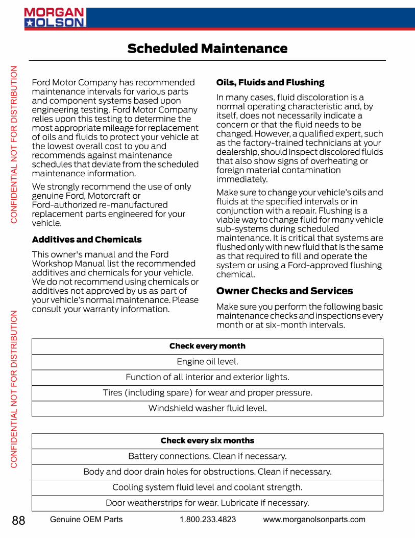
88 Genuine OEM Parts 1.800.233.4823 www.morganolsonparts.com
CO
NFI
DEN
TIAL
NO
T FO
R D
ISTR
IBU
TIO
N
C
ON
FID
ENTI
AL N
OT
FOR
DIS
TRIB
UTI
ON
Ford Motor Company has recommendedmaintenance intervals for various partsand component systems based uponengineering testing. Ford Motor Companyrelies upon this testing to determine themost appropriate mileage for replacementof oils and fluids to protect your vehicle atthe lowest overall cost to you andrecommends against maintenanceschedules that deviate from the scheduledmaintenance information.We strongly recommend the use of onlygenuine Ford, Motorcraft orFord-authorized re-manufacturedreplacement parts engineered for yourvehicle.
Additives and ChemicalsThis owner's manual and the FordWorkshop Manual list the recommendedadditives and chemicals for your vehicle.We do not recommend using chemicals oradditives not approved by us as part ofyour vehicle’s normal maintenance. Pleaseconsult your warranty information.
Oils, Fluids and FlushingIn many cases, fluid discoloration is anormal operating characteristic and, byitself, does not necessarily indicate aconcern or that the fluid needs to bechanged. However, a qualified expert, suchas the factory-trained technicians at yourdealership, should inspect discolored fluidsthat also show signs of overheating orforeign material contaminationimmediately.Make sure to change your vehicle’s oils andfluids at the specified intervals or inconjunction with a repair. Flushing is aviable way to change fluid for many vehiclesub-systems during scheduledmaintenance. It is critical that systems areflushed only with new fluid that is the sameas that required to fill and operate thesystem or using a Ford-approved flushingchemical.
Owner Checks and ServicesMake sure you perform the following basicmaintenance checks and inspections everymonth or at six-month intervals.
Check every month
Engine oil level.
Function of all interior and exterior lights.
Tires (including spare) for wear and proper pressure.
Windshield washer fluid level.
Check every six months
Battery connections. Clean if necessary.
Body and door drain holes for obstructions. Clean if necessary.
Cooling system fluid level and coolant strength.
Door weatherstrips for wear. Lubricate if necessary.
269
E-Series (TE4) Canada/United States of America, enUSA, Edition date: 03/2015, Second Printing
Scheduled Maintenance

89USPS 2 Ton Delivery Vehicle 2016 - 2018 Models
CO
NFID
ENTIAL N
OT FO
R D
ISTRIBU
TION
CO
NFID
ENTIAL N
OT FO
R D
ISTRIBU
TION
Check every six months
Hinges, latches and outside locks for proper operation. Lubricate if necessary.
Parking brake for proper operation.
Safety belts and seat latches for wear and function.
Safety warning lamps (brake, ABS, airbag and safety belt) for operation.
Washer spray and wiper operation. Clean or replace blades as necessary.
Multi-point InspectionIn order to keep your vehicle running right,it is important to have the systems on yourvehicle checked regularly. This can helpidentify potential issues and prevent majorproblems. We recommend having thefollowing multi-point inspection performedat every scheduled maintenance intervalto help make sure your vehicle keepsrunning great.
Multi-point inspection
Horn operationAccessory drive belt(s)
Radiator, cooler, heater and A/C hosesBattery performance
Suspension component for leaks ordamageEngine air filter
Steering and linkageExhaust system
Tires (including spare) for wear and properpressure**
Exterior lamps and hazard warning systemoperation
Windshield for cracks, chips or pitsFluid levels*; fill if necessary
Washer spray and wiper operationFor oil and fluid leaks* Brake, coolant recovery reservoir, automatic transmission, power steering and windowwasher.**If your vehicle is equipped with a temporary mobility kit, check the tire sealant expirationUse By date on the canister. Replace as needed.
270
E-Series (TE4) Canada/United States of America, enUSA, Edition date: 03/2015, Second Printing
Scheduled Maintenance
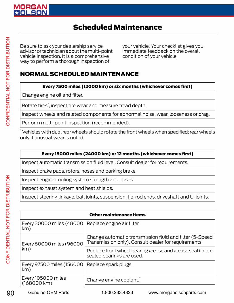
90 Genuine OEM Parts 1.800.233.4823 www.morganolsonparts.com
CO
NFI
DEN
TIAL
NO
T FO
R D
ISTR
IBU
TIO
N
C
ON
FID
ENTI
AL N
OT
FOR
DIS
TRIB
UTI
ON
Be sure to ask your dealership serviceadvisor or technician about the multi-pointvehicle inspection. It is a comprehensiveway to perform a thorough inspection of
your vehicle. Your checklist gives youimmediate feedback on the overallcondition of your vehicle.
NORMAL SCHEDULED MAINTENANCE
Every 7500 miles (12000 km) or six months (whichever comes first)
Change engine oil and filter.
Rotate tires*, inspect tire wear and measure tread depth.
Inspect wheels and related components for abnormal noise, wear, looseness or drag.
Perform multi-point inspection (recommended).* Vehicles with dual rear wheels should rotate the front wheels when specified; rear wheelsonly if unusual wear is noted.
Every 15000 miles (24000 km) or 12 months (whichever comes first)
Inspect automatic transmission fluid level. Consult dealer for requirements.
Inspect brake pads, rotors, hoses and parking brake.
Inspect engine cooling system strength and hoses.
Inspect exhaust system and heat shields.
Inspect steering linkage, ball joints, suspension, tie-rod ends, driveshaft and U-joints.
Other maintenance items
Replace engine air filter.Every 30000 miles (48000km)
Change automatic transmission fluid and filter (5-SpeedTransmission only). Consult dealer for requirements.Every 60000 miles (96000
km) Replace front wheel bearing grease and grease seal if non-sealed bearings are used.
Replace spark plugs.Every 97500 miles (156000km)
Change engine coolant.*Every 105000 miles(168000 km)
271
E-Series (TE4) Canada/United States of America, enUSA, Edition date: 03/2015, Second Printing
Scheduled Maintenance
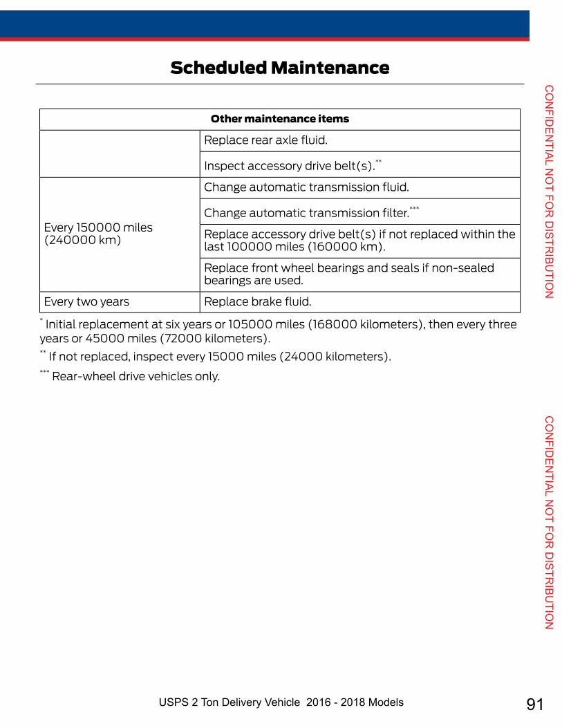
91USPS 2 Ton Delivery Vehicle 2016 - 2018 Models
CO
NFID
ENTIAL N
OT FO
R D
ISTRIBU
TION
CO
NFID
ENTIAL N
OT FO
R D
ISTRIBU
TION
Other maintenance items
Replace rear axle fluid.
Inspect accessory drive belt(s).**
Change automatic transmission fluid.
Every 150000 miles(240000 km)
Change automatic transmission filter.***
Replace accessory drive belt(s) if not replaced within thelast 100000 miles (160000 km).
Replace front wheel bearings and seals if non-sealedbearings are used.
Replace brake fluid.Every two years* Initial replacement at six years or 105000 miles (168000 kilometers), then every threeyears or 45000 miles (72000 kilometers).** If not replaced, inspect every 15000 miles (24000 kilometers).*** Rear-wheel drive vehicles only.
272
E-Series (TE4) Canada/United States of America, enUSA, Edition date: 03/2015, Second Printing
Scheduled Maintenance

92 Genuine OEM Parts 1.800.233.4823 www.morganolsonparts.com
CO
NFI
DEN
TIAL
NO
T FO
R D
ISTR
IBU
TIO
N
C
ON
FID
ENTI
AL N
OT
FOR
DIS
TRIB
UTI
ON
SPECIAL OPERATINGCONDITIONS SCHEDULEDMAINTENANCEIf you operate your vehicle primarily in anyof the following conditions, you need to
perform extra maintenance as indicated.If you operate your vehicle occasionallyunder any of these conditions, it is notnecessary to perform the extramaintenance. For specificrecommendations, see your dealershipservice advisor or technician.
Towing a trailer or using a car-top carrier
Inspect U-joints.Inspect frequently, serviceas required
See axle maintenance items under Exceptions.
Inspect the wheels and related components for abnormalnoise, wear, looseness or drag.
Every 5000 miles (8000km)
Rotate tires*, inspect tires for wear and measure treaddepth.
Change engine oil and filter.Every 5000 miles (8000km) or six months
Inspect U-joints.
Replace front wheel bearing grease and grease seals ifnon-sealed bearings are used.
Every 30000 miles (48000km)
Replace spark plugs.Every 60000 miles (96000km)
*Vehicles equipped with dual rear wheels should rotate the front wheels when specified;rear wheels only if unusual wear is noted.
Extensive idling or low-speed driving for long distances, as in heavy commercial use(such as delivery, taxi, patrol car or livery)
Inspect brake system.Every 5000 miles (8000km)
Inspect wheels and related components for abnormalnoise, wear, looseness or drag.
Rotate tires*, inspect tires for wear and measure treaddepth.
Inspect U-joints.Every 5000 miles (8000km) or six months
273
E-Series (TE4) Canada/United States of America, enUSA, Edition date: 03/2015, Second Printing
Scheduled Maintenance

93USPS 2 Ton Delivery Vehicle 2016 - 2018 Models
CO
NFID
ENTIAL N
OT FO
R D
ISTRIBU
TION
CO
NFID
ENTIAL N
OT FO
R D
ISTRIBU
TION
Extensive idling or low-speed driving for long distances, as in heavy commercial use(such as delivery, taxi, patrol car or livery)
Change engine oil and filter.Every 5000 miles (8000km) or six months or 200engine hours
Replace front wheel bearing grease and grease seals ifnon-sealed bearings are used.
Every 30000 miles (48000km)
Replace spark plugs.Every 60000 miles (96000km)
*Vehicles equipped with dual rear wheels should rotate the front wheels when specified;rear wheels only if unusual wear is noted.
Operating in dusty or sandy conditions (such as unpaved or dusty roads)
Replace engine air filter.Inspect frequently, serviceas required
Inspect the wheels and related components for abnormalnoise, wear, looseness or drag.
Every 5000 miles (8000km)
Rotate tires*, inspect tires for wear and measure treaddepth.
Change engine oil and filter.Every 5000 miles (8000km) or six months
Inspect U-joints.
Replace front wheel bearing grease and grease seals ifnon-sealed bearings are used.
Every 30000 miles (48000km)
Change rear axle fluid.Every 50000 miles (80000km)
*Vehicles equipped with dual rear wheels should rotate the front wheels when specified;rear wheels only if unusual wear is noted.
ExceptionsThere are several exceptions to the NormalSchedule:
Normal vehicle axle maintenance: Rearaxles and power take-off units withsynthetic fluid and light-duty trucksequipped with Ford-design axles arelubricated for life; do not check or changefluid unless a leak is suspected, service isrequired or the assembly has beensubmerged in water. During long periodsof trailer towing with outside temperatures
274
E-Series (TE4) Canada/United States of America, enUSA, Edition date: 03/2015, Second Printing
Scheduled Maintenance
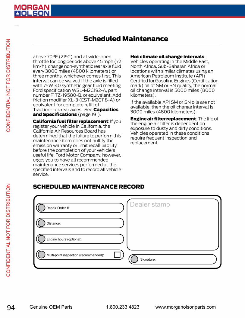
94 Genuine OEM Parts 1.800.233.4823 www.morganolsonparts.com
CO
NFI
DEN
TIAL
NO
T FO
R D
ISTR
IBU
TIO
N
C
ON
FID
ENTI
AL N
OT
FOR
DIS
TRIB
UTI
ON
above 70°F (21°C) and at wide-openthrottle for long periods above 45 mph (72km/h), change non-synthetic rear axle fluidevery 3000 miles (4800 kilometers) orthree months, whichever comes first. Thisinterval can be waived if the axle is filledwith 75W140 synthetic gear fluid meetingFord specification WSL-M2C192-A, partnumber F1TZ-19580-B, or equivalent. Addfriction modifier XL-3 (EST-M2C118-A) orequivalent for complete refill ofTraction-Lok rear axles. See Capacitiesand Specifications (page 191).California fuel filter replacement: If youregister your vehicle in California, theCalifornia Air Resources Board hasdetermined that the failure to perform thismaintenance item does not nullify theemission warranty or limit recall liabilitybefore the completion of your vehicle'suseful life. Ford Motor Company, however,urges you to have all recommendedmaintenance services performed at thespecified intervals and to record all vehicleservice.
Hot climate oil change intervals:Vehicles operating in the Middle East,North Africa, Sub-Saharan Africa orlocations with similar climates using anAmerican Petroleum Institute (API)Certified for Gasoline Engines (Certificationmark) oil of SM or SN quality, the normaloil change interval is 5000 miles (8000kilometers).If the available API SM or SN oils are notavailable, then the oil change interval is3000 miles (4800 kilometers).Engine air filter replacement: The life ofthe engine air filter is dependent onexposure to dusty and dirty conditions.Vehicles operated in these conditionsrequire frequent inspection andreplacement.
SCHEDULED MAINTENANCE RECORD
E146852
Repair Order #:
Distance:
Engine hours (optional):
Multi-point inspection (recommended):Signature:
Dealer stamp
275
E-Series (TE4) Canada/United States of America, enUSA, Edition date: 03/2015, Second Printing
Scheduled Maintenance

95USPS 2 Ton Delivery Vehicle 2016 - 2018 Models
CO
NFID
ENTIAL N
OT FO
R D
ISTRIBU
TION
CO
NFID
ENTIAL N
OT FO
R D
ISTRIBU
TION
Mile
age
5K10
K15
K20
K25
K30
K35
K40
K45
K50
K55
K60
K65
K70
K75
K80
K85
K90
K95
K10
0K10
5K11
0K11
5K12
0K12
5K13
0K13
5K14
0K14
5K15
0K
MEM
O: G
as e
ngin
e;
Up to
6.0
qua
rts o
f oil
XX
XX
XX
XX
XX
XX
XX
XX
XX
XX
XX
XX
XX
XX
XX
Repl
ace
plati
-nu
m-ti
pped
spar
k pl
ugs
XX
Insp
ect c
ompl
ete
exha
ust s
yste
m a
nd
heat
shie
lds
XX
XX
X
Repl
ace
front
4x2
w
heel
bea
rings
and
gr
ease
seal
s, lu
brica
te
and
adju
st b
earin
gs
X
Repl
ace
acce
ssor
y dr
ive
belts
(if n
ot
repl
aced
with
in la
st
100,
000
mile
s)
X
Chan
ge P
rem
ium
Gol
d en
gine
cool
ant
XX
Repl
ace
rear
axl
e lu
brica
ntX
Insp
ect a
nd lu
brica
te
all n
on-s
eale
d st
eerin
g lin
kage
,bal
l joi
nts,
-su
spen
sion
join
ts,h
alf
and
driv
e-sh
afts a
nd
u-jo
ints
XX
XX
XX
XX
XX
XX
XX
XX
XX
XX
XX
XX
X
Insp
ect 4
x2 fr
ont
whe
el b
earin
gs;
repl
ace
grea
se a
nd
grea
se se
als,
and
adju
st b
earin
gs
XX
XX
X
Chan
ge re
ar a
xle
fluid
(v
ehic
les e
quip
ped
with
Dan
a ax
les)
X
Chan
ge a
utom
atic
tran
smiss
ion
fluid
and
fil
ter
XX
Insp
ect b
rake
pad
s/sh
oes/
roto
rs/d
rum
s, br
ake
lines
and
hos
es,
and
park
ing
brak
e sy
stem
XX
XX
XX
XX
XX
XX
XX
XX
XX
XX
XX
XX
X
Insp
ect c
oolin
g sy
stem
an
d ho
ses
XX
XX
X
Insp
ect a
cces
sory
dr
ive
belt(
s)X
X
FORD
Rec
omm
ende
d M
aint
enan
ce S
ched
ule
For E
xtre
me
Duty
Ext
ensi
ve id
ling
and/
or d
rivin
g at
low
spee
ds
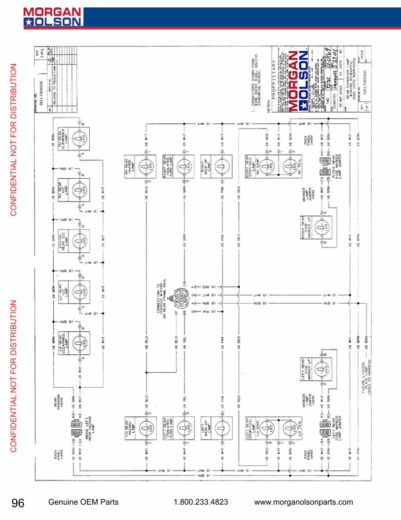
96 Genuine OEM Parts 1.800.233.4823 www.morganolsonparts.com
CO
NFI
DEN
TIAL
NO
T FO
R D
ISTR
IBU
TIO
N
C
ON
FID
ENTI
AL N
OT
FOR
DIS
TRIB
UTI
ON
31
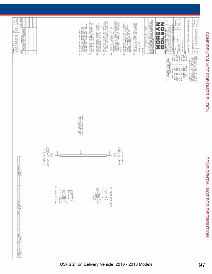
97USPS 2 Ton Delivery Vehicle 2016 - 2018 Models
CO
NFID
ENTIAL N
OT FO
R D
ISTRIBU
TION
CO
NFID
ENTIAL N
OT FO
R D
ISTRIBU
TION
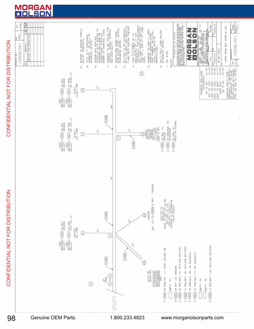
98 Genuine OEM Parts 1.800.233.4823 www.morganolsonparts.com
CO
NFI
DEN
TIAL
NO
T FO
R D
ISTR
IBU
TIO
N
C
ON
FID
ENTI
AL N
OT
FOR
DIS
TRIB
UTI
ON

99USPS 2 Ton Delivery Vehicle 2016 - 2018 Models
CO
NFID
ENTIAL N
OT FO
R D
ISTRIBU
TION
CO
NFID
ENTIAL N
OT FO
R D
ISTRIBU
TION
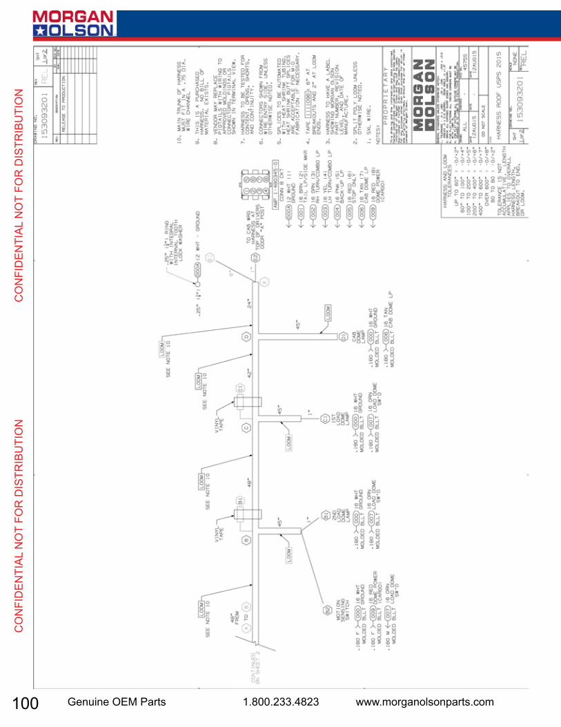
100 Genuine OEM Parts 1.800.233.4823 www.morganolsonparts.com
CO
NFI
DEN
TIAL
NO
T FO
R D
ISTR
IBU
TIO
N
C
ON
FID
ENTI
AL N
OT
FOR
DIS
TRIB
UTI
ON

101USPS 2 Ton Delivery Vehicle 2016 - 2018 Models
CO
NFID
ENTIAL N
OT FO
R D
ISTRIBU
TION
CO
NFID
ENTIAL N
OT FO
R D
ISTRIBU
TION
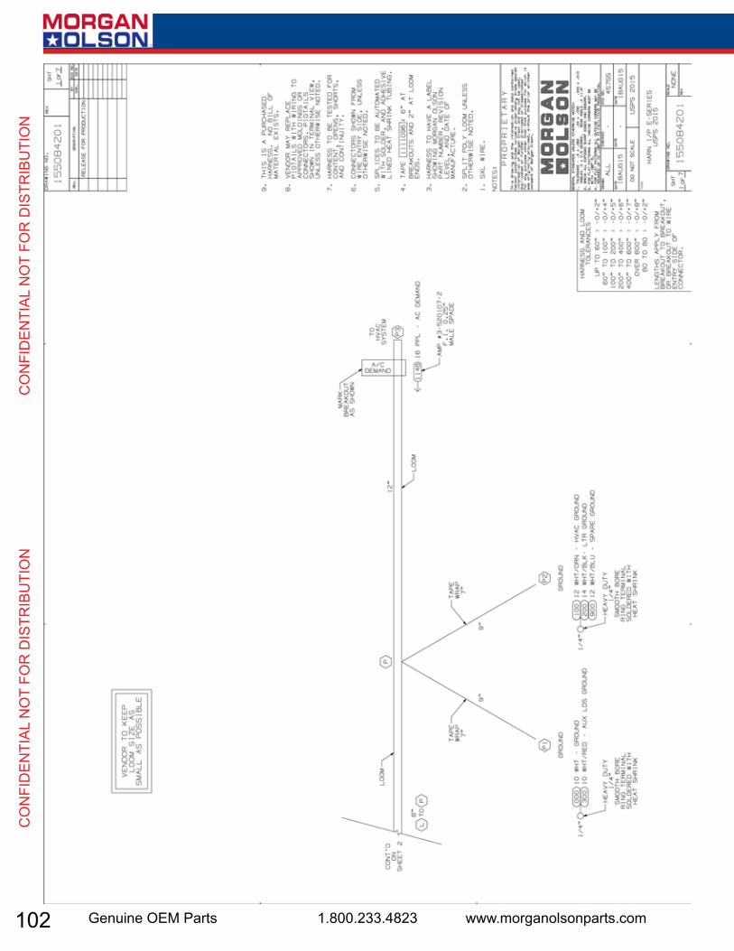
102 Genuine OEM Parts 1.800.233.4823 www.morganolsonparts.com
CO
NFI
DEN
TIAL
NO
T FO
R D
ISTR
IBU
TIO
N
C
ON
FID
ENTI
AL N
OT
FOR
DIS
TRIB
UTI
ON
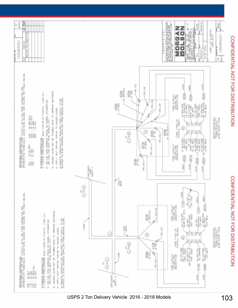
103USPS 2 Ton Delivery Vehicle 2016 - 2018 Models
CO
NFID
ENTIAL N
OT FO
R D
ISTRIBU
TION
CO
NFID
ENTIAL N
OT FO
R D
ISTRIBU
TION
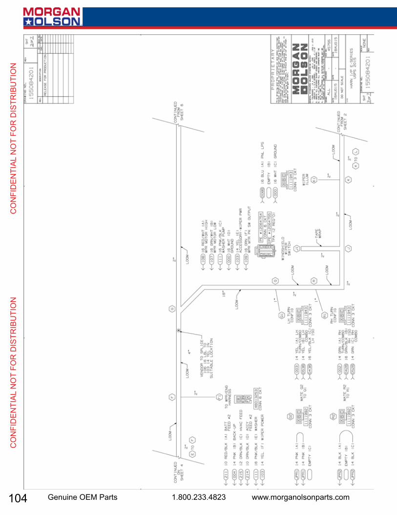
104 Genuine OEM Parts 1.800.233.4823 www.morganolsonparts.com
CO
NFI
DEN
TIAL
NO
T FO
R D
ISTR
IBU
TIO
N
C
ON
FID
ENTI
AL N
OT
FOR
DIS
TRIB
UTI
ON
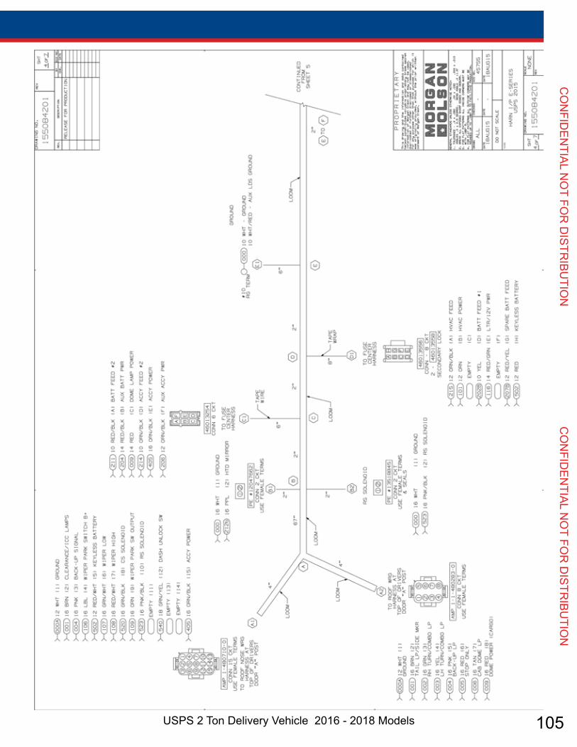
105USPS 2 Ton Delivery Vehicle 2016 - 2018 Models
CO
NFID
ENTIAL N
OT FO
R D
ISTRIBU
TION
CO
NFID
ENTIAL N
OT FO
R D
ISTRIBU
TION
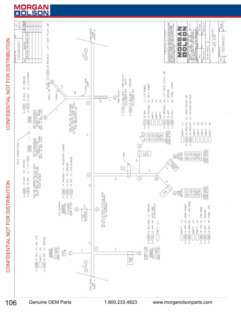
106 Genuine OEM Parts 1.800.233.4823 www.morganolsonparts.com
CO
NFI
DEN
TIAL
NO
T FO
R D
ISTR
IBU
TIO
N
C
ON
FID
ENTI
AL N
OT
FOR
DIS
TRIB
UTI
ON
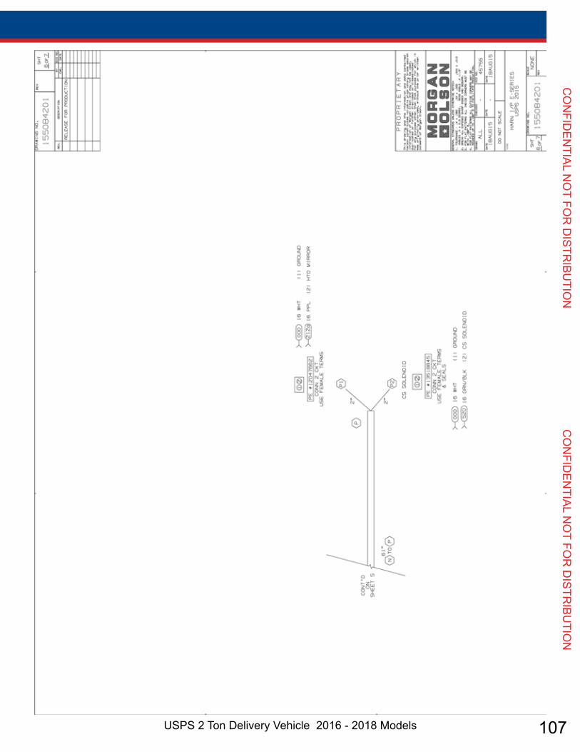
107USPS 2 Ton Delivery Vehicle 2016 - 2018 Models
CO
NFID
ENTIAL N
OT FO
R D
ISTRIBU
TION
CO
NFID
ENTIAL N
OT FO
R D
ISTRIBU
TION
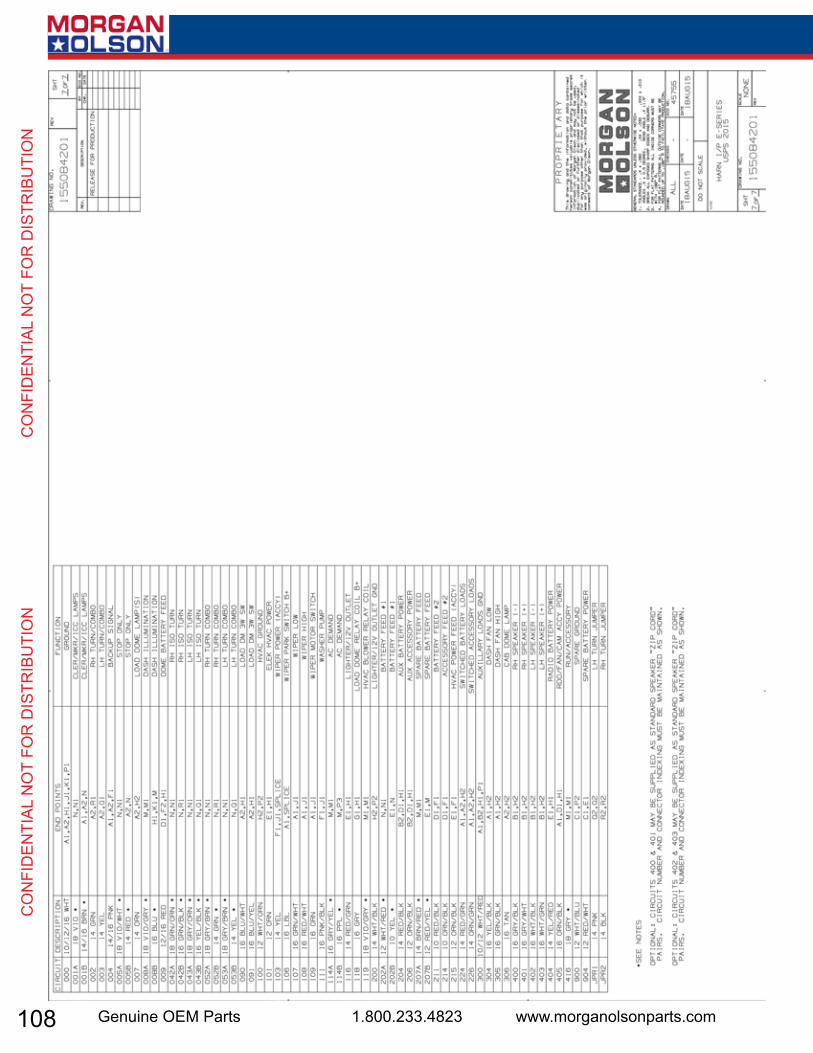
108 Genuine OEM Parts 1.800.233.4823 www.morganolsonparts.com
CO
NFI
DEN
TIAL
NO
T FO
R D
ISTR
IBU
TIO
N
C
ON
FID
ENTI
AL N
OT
FOR
DIS
TRIB
UTI
ON

109USPS 2 Ton Delivery Vehicle 2016 - 2018 Models
CO
NFID
ENTIAL N
OT FO
R D
ISTRIBU
TION
CO
NFID
ENTIAL N
OT FO
R D
ISTRIBU
TION
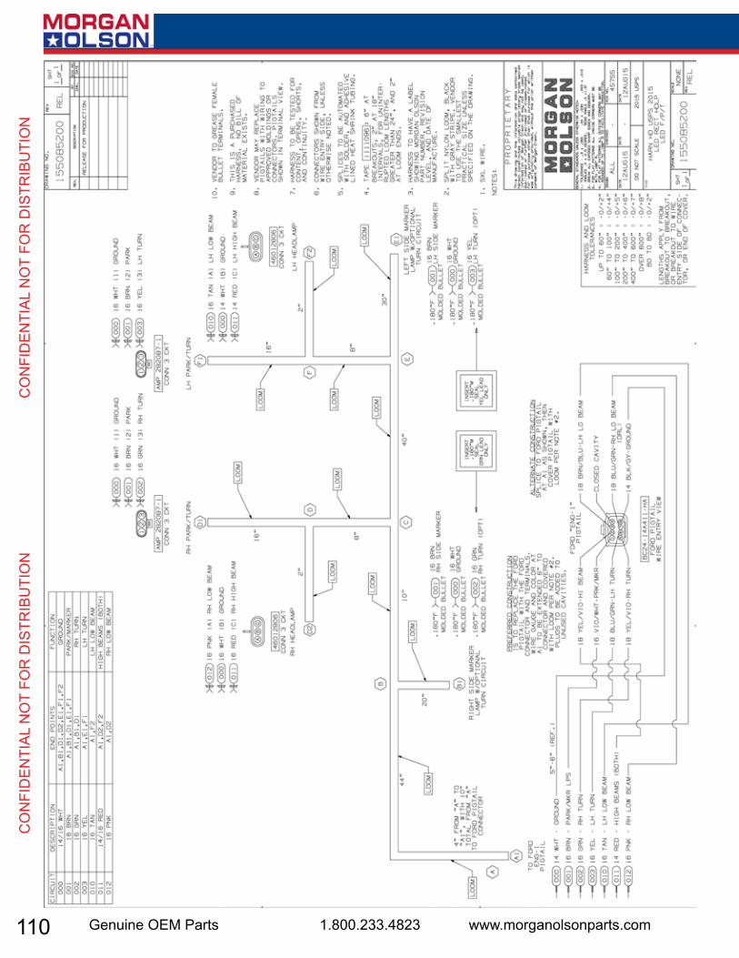
110 Genuine OEM Parts 1.800.233.4823 www.morganolsonparts.com
CO
NFI
DEN
TIAL
NO
T FO
R D
ISTR
IBU
TIO
N
C
ON
FID
ENTI
AL N
OT
FOR
DIS
TRIB
UTI
ON
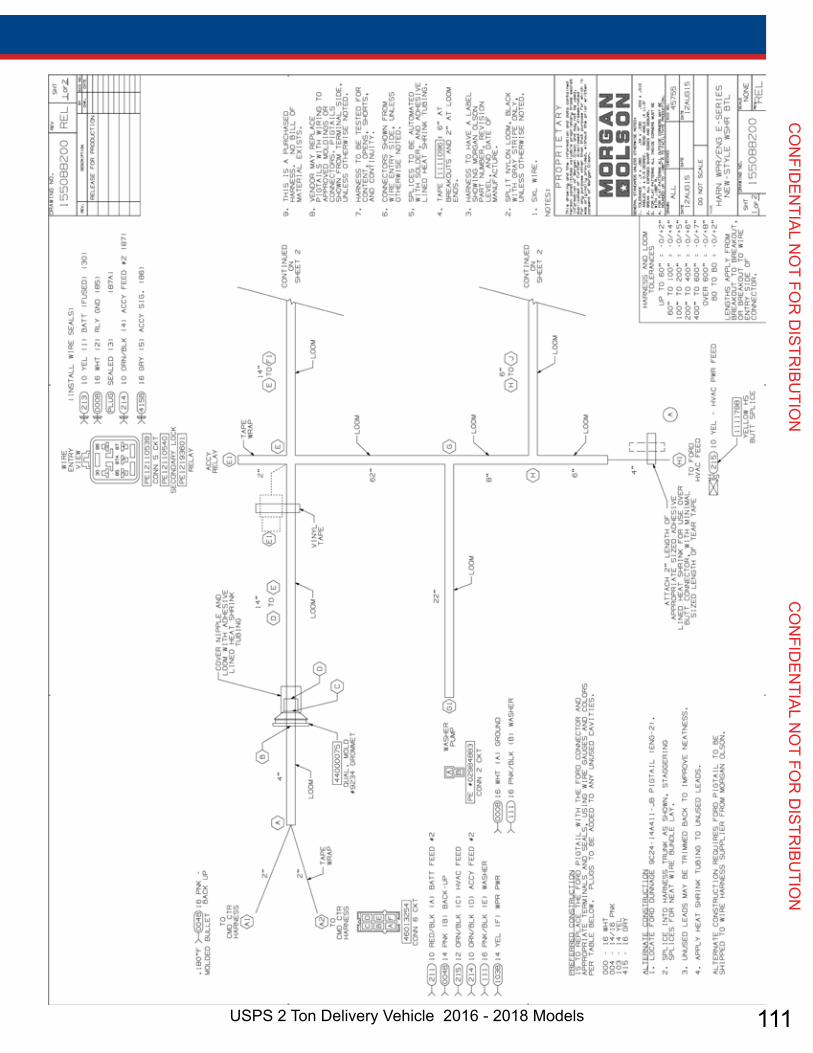
111USPS 2 Ton Delivery Vehicle 2016 - 2018 Models
CO
NFID
ENTIAL N
OT FO
R D
ISTRIBU
TION
CO
NFID
ENTIAL N
OT FO
R D
ISTRIBU
TION
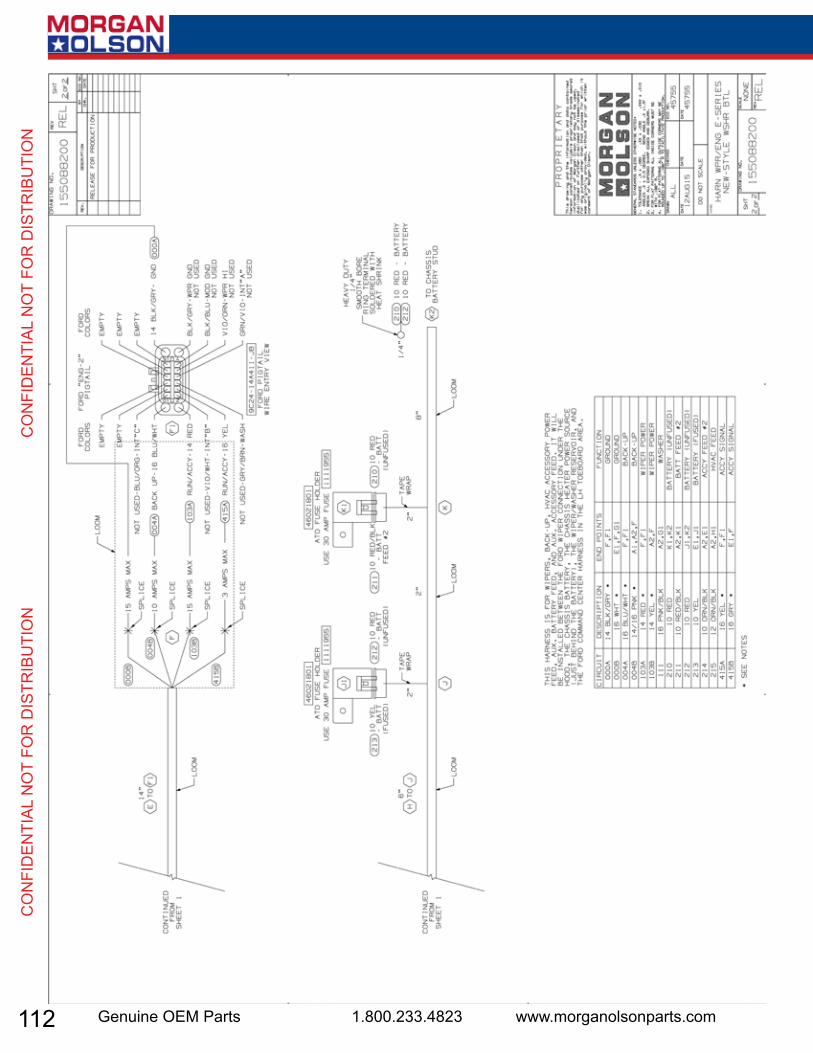
112 Genuine OEM Parts 1.800.233.4823 www.morganolsonparts.com
CO
NFI
DEN
TIAL
NO
T FO
R D
ISTR
IBU
TIO
N
C
ON
FID
ENTI
AL N
OT
FOR
DIS
TRIB
UTI
ON
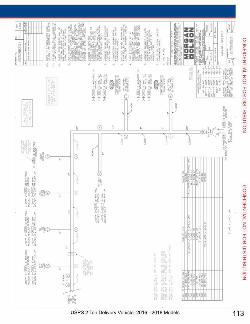
113USPS 2 Ton Delivery Vehicle 2016 - 2018 Models
CO
NFID
ENTIAL N
OT FO
R D
ISTRIBU
TION
CO
NFID
ENTIAL N
OT FO
R D
ISTRIBU
TION

114 Genuine OEM Parts 1.800.233.4823 www.morganolsonparts.com
CO
NFI
DEN
TIAL
NO
T FO
R D
ISTR
IBU
TIO
N
C
ON
FID
ENTI
AL N
OT
FOR
DIS
TRIB
UTI
ON

115USPS 2 Ton Delivery Vehicle 2016 - 2018 Models
CO
NFID
ENTIAL N
OT FO
R D
ISTRIBU
TION
CO
NFID
ENTIAL N
OT FO
R D
ISTRIBU
TION
Notes________________________________________________________________________________________________________________________________________________________________________________________________________________________________________________________________________________________________________________________________________________________________________________________________________________________________________________________________________________________________________________________________________________________________________________________________________________________________________________________________________________________________________________________________________________________________________________________________________________________________________________________________________________________________________________________________________________________________________________________________________________________________________________________________________________________________________________________________________________________________________________________________________________________________________________________________________________________________________________________________________________________________________________________________________________________________________________________________________________________________________________________________________________________________________________________________________________________________________________________________________________________________________________________________________________________________________________________________________________________________________________________________________________________________________________________________________________________________________________________________________________________________________________________________________________________________________________________________________________________________________________________________________________________________________________________________________________________________________________________________________________________________________________________________________________________________________________________________________________________________________________________________________________________________________________________________________________________________________________________________________________________________________________________________________________________________________________________________________________________________________________________________________________________________________________________________________________________________________________________________________________________________________________________________________________________________________________________________________________________________________________________________________________________________________________________________________________________________________________________________________________________________________________________________________________________________________________________________________________________________________________________________________________________________________________________________________________________________________________________________________________________________________________________________________________________________________________________________________________________________________________________________________________________________________________________________________