service manual for installers - sunny tripower...
TRANSCRIPT

Service Manual for InstallersSUNNY TRIPOWER 15000TL / 17000TL /20000TL / 25000TL
STP15-25TL-30-SG-en-12 | Version 1.2ENGLISH

Legal ProvisionsThe information contained in these documents is property of SMA Solar Technology AG. Anypublication, whether in whole or in part, requires prior written approval by SMA Solar TechnologyAG. Internal reproduction used solely for the purpose of product evaluation or other proper use isallowed and does not require prior approval.
SMA WarrantyYou can download the current warranty conditions from the Internet at www.SMA-Solar.com.
TrademarksAll trademarks are recognized, even if not explicitly identified as such. Missing designations do notmean that a product or brand is not a registered trademark.Modbus® is a registered trademark of Schneider Electric and is licensed by theModbus Organization, Inc.QR Code is a registered trademark of DENSO WAVE INCORPORATED.Phillips® and Pozidriv® are registered trademarks of Phillips Screw Company.Torx® is a registered trademark of Acument Global Technologies, Inc.
SMA Solar Technology AGSonnenallee 134266 NiestetalGermanyTel. +49 561 9522-0Fax +49 561 9522-100www.SMA.deEmail: [email protected] © 2016 SMA Solar Technology AG. All rights reserved.
Legal Provisions SMA Solar Technology AG
Service Manual for InstallersSTP15-25TL-30-SG-en-122

Table of Contents1 Information on this Document................................................. 4
1.1 Validity ............................................................................................... 41.2 Target group ...................................................................................... 41.3 Symbols.............................................................................................. 41.4 Nomenclature .................................................................................... 5
2 Safety ........................................................................................ 62.1 Safety Information ............................................................................. 62.2 Disconnecting the Inverter from Voltage Sources............................ 7
3 Cleaning the Inverter ............................................................... 11
4 Retrofitting the Surge Arrester Type II.................................... 12
5 Troubleshooting........................................................................ 135.1 Event Messages................................................................................. 135.2 Error Messages.................................................................................. 14
6 Cleaning the Fans..................................................................... 236.1 Cleaning the Fan at the Bottom ........................................................ 236.2 Cleaning the Fan on the Left-Hand Side of the Enclosure............... 24
7 Checking the Function of the Fans .......................................... 27
8 Checking the PV System for Ground Faults ........................... 28
9 Checking the Function of the Surge Arresters........................ 32
10 Replacing the Surge Arrester .................................................. 34
11 Recommissioning the Inverter ................................................. 36
12 Procedure for Receiving a Replacement Device.................... 39
13 Decommissioning the Inverter................................................. 43
14 Spare Parts ............................................................................... 45
15 Contact ...................................................................................... 46
Table of ContentsSMA Solar Technology AG
Service Manual for Installers 3STP15-25TL-30-SG-en-12

1 Information on this Document
1.1 ValidityThis document describes how to rectify certain errors and how to replace defective components.This document supplements the documents that are enclosed with each product and does notreplace any locally applicable standards or directives. Read and observe all documents suppliedwith the product.This document is valid for the following device types:
• STP 15000TL-30 (Sunny Tripower 15000TL)• STP 17000TL-30 (Sunny Tripower 17000TL) (This device is only available as a service
product)• STP 20000TL-30 (Sunny Tripower 20000TL)• STP 25000TL-30 (Sunny Tripower 25000TL)
1.2 Target groupThe tasks described in this document must only be performed by qualified persons. Qualifiedpersons must have the following skills:
• Knowledge of how an inverter works and is operated• Training in how to deal with the dangers and risks associated with installing and using
electrical devices and installations• Training in the installation and commissioning of electrical devices and installations• Knowledge of the applicable standards and directives• Knowledge of and compliance with this document and all safety information
1.3 SymbolsSymbol Explanation
Indicates a hazardous situation which, if notavoided, will result in death or serious injury
Indicates a hazardous situation which, if notavoided, can result in death or serious injury
Indicates a hazardous situation which, if notavoided, can result in minor or moderate injury
Indicates a situation which, if not avoided, canresult in property damage
Information that is important for a specific topicor goal, but is not safety-relevant
Indicates a requirement for meeting a specificgoal
1 Information on this Document SMA Solar Technology AG
Service Manual for InstallersSTP15-25TL-30-SG-en-124

Symbol ExplanationDesired result
A problem that might occur
1.4 NomenclatureComplete designation Designation in this documentSunny Tripower Inverter, product
1 Information on this DocumentSMA Solar Technology AG
Service Manual for Installers 5STP15-25TL-30-SG-en-12

2 Safety
2.1 Safety InformationThis section contains safety information that must be observed at all times when working on or withthe product.To prevent personal injury and property damage and to ensure long-term operation of the product,read this section carefully and observe all safety information at all times.
Danger to life due to high voltages of the PV arrayWhen exposed to sunlight, the PV array generates dangerous DC voltage, which is present in theDC conductors and the live components of the inverter. Touching the DC conductors or the livecomponents can lead to lethal electric shocks. If you disconnect the DC connectors from theinverter under load, an electric arc may occur leading to electric shock and burns.
• Do not touch non-insulated cable ends.• Do not touch the DC conductors.• Do not touch any live components of the inverter.• Have the inverter mounted, installed and commissioned only by qualified persons with the
appropriate skills.• If an error occurs, have it rectified by qualified persons only.• Prior to performing any work on the inverter, disconnect it from all voltage sources as
described in this document.
Danger to life due to electric shockTouching an ungrounded PV module or array frame can cause a lethal electric shock.
• Connect and ground the PV modules, array frame and electrically conductive surfaces sothat there is continuous conduction. Observe the applicable local regulations.
Risk of burns due to hot enclosure partsSome parts of the enclosure can get hot during operation.
• Do not touch any parts other than the lower enclosure lid of the inverter during operation.
2 Safety SMA Solar Technology AG
Service Manual for InstallersSTP15-25TL-30-SG-en-126
Damage to seals on the enclosure lids in subfreezing conditionsIf you open the upper and lower enclosure lids when temperatures are below freezing, theenclosure seals can be damaged. This can lead to moisture entering the inverter.
• Do not open the inverter at ambient temperatures lower than -5°C.• If a layer of ice has formed on the seal of the lid when temperatures are below freezing,
remove it prior to opening the enclosure lids of the inverter (e.g. by melting the ice withwarm air). Observe the applicable safety regulations.
2.2 Disconnecting the Inverter from Voltage SourcesPrior to performing any work on the inverter, always disconnect it from all voltage sources asdescribed in this section. Always adhere to the prescribed sequence.
Damage to seals on the enclosure lids in subfreezing conditionsIf you open the upper and lower enclosure lids when temperatures are below freezing, theenclosure seals can be damaged. This can lead to moisture entering the inverter.
• Do not open the inverter at ambient temperatures lower than -5°C.• If a layer of ice has formed on the seal of the lid when temperatures are below freezing,
remove it prior to opening the enclosure lids of the inverter (e.g. by melting the ice withwarm air). Observe the applicable safety regulations.
Destruction of the measuring device due to overvoltage• Only use measuring devices with a DC input voltage range of 1000 V or higher.
Procedure:1. Disconnect the circuit breaker from all three line conductors and secure it against
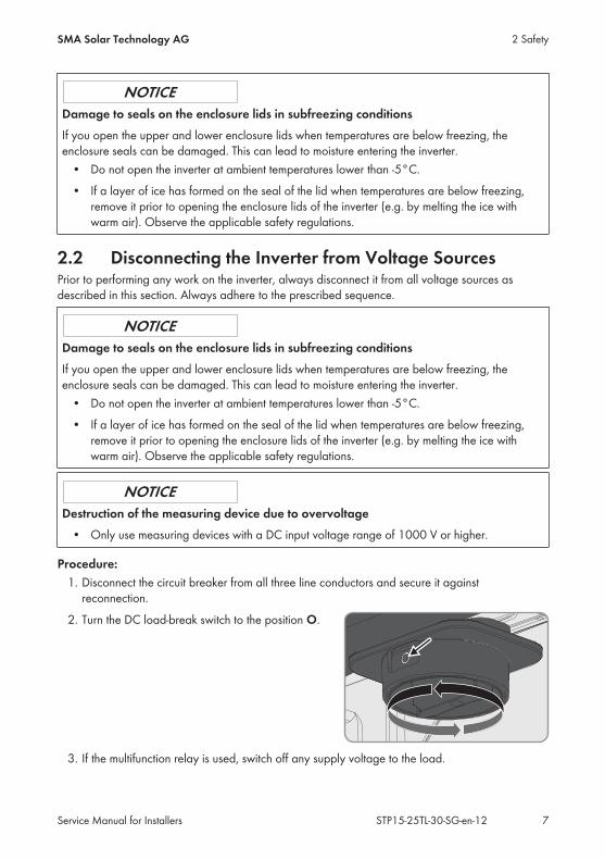
reconnection.2. Turn the DC load-break switch to the position O.
3. If the multifunction relay is used, switch off any supply voltage to the load.
2 SafetySMA Solar Technology AG
Service Manual for Installers 7STP15-25TL-30-SG-en-12
4. Wait until the LEDs have gone out and, if necessary, the load connected to the multifunctionrelay has been switched off.
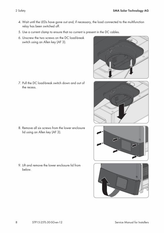
5. Use a current clamp to ensure that no current is present in the DC cables.6. Unscrew the two screws on the DC load-break
switch using an Allen key (AF 3).
7. Pull the DC load-break switch down and out ofthe recess.
8. Remove all six screws from the lower enclosurelid using an Allen key (AF 3).
9. Lift and remove the lower enclosure lid frombelow.
2 Safety SMA Solar Technology AG
Service Manual for InstallersSTP15-25TL-30-SG-en-128

10.
Risk of burns when touching the DC protective coverThe DC protective cover can get hot during operation.
• Do not touch the DC protective cover.11. Release and remove all DC connectors. Insert a
slotted screwdriver or an angled screwdriver(blade width 3.5 mm) into one of the slide slotsand pull the DC connectors out downwards. Donot pull on the cable.
12. Ensure that no voltage is present at the DC inputs of the inverter.13. Use an appropriate measuring device to ensure
that no voltage is present at the AC connectingterminal plate between L1 and N, L2 and N,and L3 and N. Insert the test probe of themultimeter into the round opening of theterminal.
14. Use an appropriate measuring device to ensure that no voltage is present at the ACconnecting terminal plate between L1 and PE, L2 and PE, and L3 and PE. Insert the testprobe into the round opening of each terminal.
15. Ensure that no voltage is present between any terminal of the multifunction relay and PE of theAC connecting terminal plate.
16.
Danger to life due to high voltages in the inverterThe capacitors in the inverter take 20 minutes to discharge.
• Wait 20 minutes before opening the upper enclosure lid.• Do not open the DC protective cover.
2 SafetySMA Solar Technology AG
Service Manual for Installers 9STP15-25TL-30-SG-en-12
17.
Damage to the inverter due to electrostatic dischargeTouching electronic components can cause damage to or destroy the inverter throughelectrostatic discharge.
• Ground yourself before touching any component.
2 Safety SMA Solar Technology AG
Service Manual for InstallersSTP15-25TL-30-SG-en-1210
3 Cleaning the Inverter
Damage to the inverter due to the use of cleaning agents• If the inverter is dirty, clean the enclosure, the enclosure lid, the type label and the LEDs
using only clean water and a cloth.
• Ensure that the inverter is free of dust, foliage and other dirt.
3 Cleaning the InverterSMA Solar Technology AG
Service Manual for Installers 11STP15-25TL-30-SG-en-12

4 Retrofitting the Surge Arrester Type IIThe inverter is equipped ex works with surge arresters or it can be retrofitted (see Section 14"Spare Parts", page 45).
1.
Danger to life due to high voltages• Disconnect the inverter from all voltage sources (see Section 2.2, page 7).• Wait 20 minutes before you remove the DC protective cover to allow residual voltages
to discharge.2. Release the screws on the DC protective cover
using an Allen key (AF 3), lift the DC protectivecover upwards from below and remove it.
3. Plug the new surge arresters into the designatedslots until they lock into place with the lockingtabs. The inspection window must be located onthe right-hand side.
4. Position the DC protective cover at the upper edge, flip down and tighten it (torque: 3.5 Nm).
4 Retrofitting the Surge Arrester Type II SMA Solar Technology AG
Service Manual for InstallersSTP15-25TL-30-SG-en-1212
5 Troubleshooting
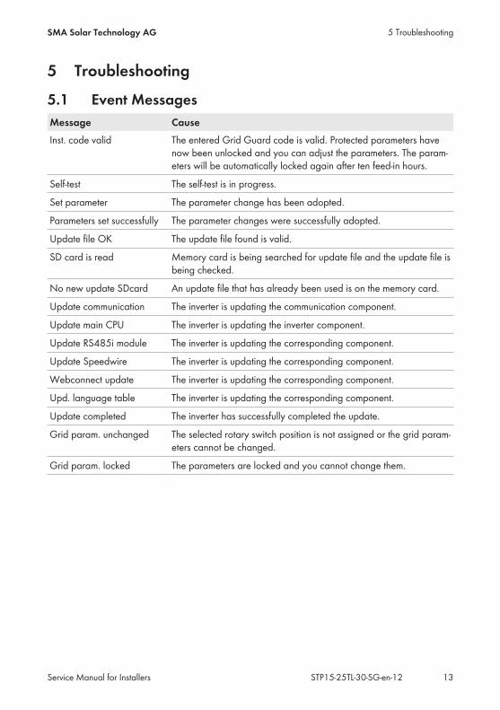
5.1 Event MessagesMessage CauseInst. code valid The entered Grid Guard code is valid. Protected parameters have
now been unlocked and you can adjust the parameters. The param-eters will be automatically locked again after ten feed-in hours.
Self-test The self-test is in progress.
Set parameter The parameter change has been adopted.
Parameters set successfully The parameter changes were successfully adopted.
Update file OK The update file found is valid.
SD card is read Memory card is being searched for update file and the update file isbeing checked.
No new update SDcard An update file that has already been used is on the memory card.
Update communication The inverter is updating the communication component.
Update main CPU The inverter is updating the inverter component.
Update RS485i module The inverter is updating the corresponding component.
Update Speedwire The inverter is updating the corresponding component.
Webconnect update The inverter is updating the corresponding component.
Upd. language table The inverter is updating the corresponding component.
Update completed The inverter has successfully completed the update.
Grid param. unchanged The selected rotary switch position is not assigned or the grid param-eters cannot be changed.
Grid param. locked The parameters are locked and you cannot change them.
5 TroubleshootingSMA Solar Technology AG
Service Manual for Installers 13STP15-25TL-30-SG-en-12

5.2 Error MessagesThe communication product (e.g. Sunny Explorer) displays the warnings and errors that apply tothe inverter, the utility grid or the PV array. The warning or error is identified by an event numberand the corresponding message.
Event number Message, cause and corrective measures101 … 103 Grid fault
The grid voltage or grid impedance at the connection point of the inverter istoo high. The inverter has disconnected from the utility grid.Corrective measures:
• Check whether the grid voltage at the connection point of the inverter ispermanently in the permissible range.
If the grid voltage is outside the permissible range due to local gridconditions, contact the grid operator. The grid operator must agree withan adjustment of the voltage at the feed-in point or with a change of themonitored operating limits.If the grid voltage is permanently within the permissible range and thismessage is still displayed, contact the SMA Service Line.
202 … 203 Grid faultThe utility grid has been disconnected, the AC cable is damaged or the gridvoltage at the connection point of the inverter is too low. The inverter has dis-connected from the utility grid.Corrective measures:
1. Make sure that the circuit breaker is switched on.2. Make sure that the AC cable is not damaged.3. Make sure that the AC cable is correctly connected.4. Check whether the grid voltage at the connection point of the inverter is
permanently in the permissible range.If the grid voltage is outside the permissible range due to local grid conditions,contact the grid operator. The grid operator must agree with an adjustment ofthe voltage at the feed-in point or with a change of the monitored operatinglimits.If the grid voltage is permanently within the permissible range and thismessage is still displayed, contact the SMA Service Line.
5 Troubleshooting SMA Solar Technology AG
Service Manual for InstallersSTP15-25TL-30-SG-en-1214
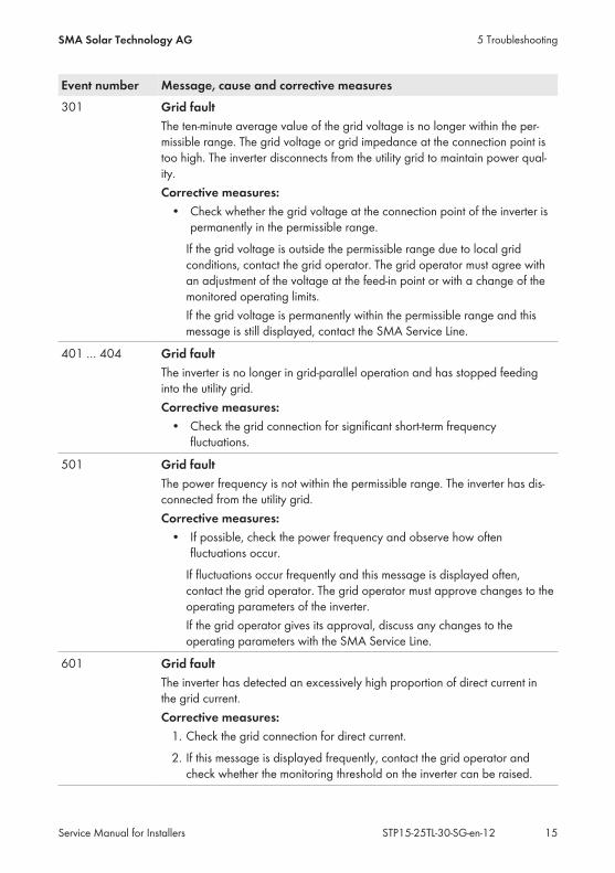
Event number Message, cause and corrective measures301 Grid fault
The ten-minute average value of the grid voltage is no longer within the per-missible range. The grid voltage or grid impedance at the connection point istoo high. The inverter disconnects from the utility grid to maintain power qual-ity.Corrective measures:
• Check whether the grid voltage at the connection point of the inverter ispermanently in the permissible range.
If the grid voltage is outside the permissible range due to local gridconditions, contact the grid operator. The grid operator must agree withan adjustment of the voltage at the feed-in point or with a change of themonitored operating limits.If the grid voltage is permanently within the permissible range and thismessage is still displayed, contact the SMA Service Line.
401 … 404 Grid faultThe inverter is no longer in grid-parallel operation and has stopped feedinginto the utility grid.Corrective measures:
• Check the grid connection for significant short-term frequencyfluctuations.
501 Grid faultThe power frequency is not within the permissible range. The inverter has dis-connected from the utility grid.Corrective measures:
• If possible, check the power frequency and observe how oftenfluctuations occur.
If fluctuations occur frequently and this message is displayed often,contact the grid operator. The grid operator must approve changes to theoperating parameters of the inverter.If the grid operator gives its approval, discuss any changes to theoperating parameters with the SMA Service Line.
601 Grid faultThe inverter has detected an excessively high proportion of direct current inthe grid current.Corrective measures:
1. Check the grid connection for direct current.2. If this message is displayed frequently, contact the grid operator and
check whether the monitoring threshold on the inverter can be raised.
5 TroubleshootingSMA Solar Technology AG
Service Manual for Installers 15STP15-25TL-30-SG-en-12

Event number Message, cause and corrective measures701 Frq. not permitted > Check parameter
The power frequency is not within the permissible range. The inverter has dis-connected from the utility grid.Corrective measures:
• If possible, check the power frequency and observe how oftenfluctuations occur.
If fluctuations occur frequently and this message is displayed often,contact the grid operator. The grid operator must approve changes to theoperating parameters of the inverter.If the grid operator gives its approval, discuss any changes to theoperating parameters with the SMA Service Line.
1302 Waiting for grid voltage > Installation failure grid connection > Checkgrid and fusesThe inverter has detected an error in the AC cabling. The inverter cannot con-nect to the utility grid.Corrective measures:
1. Ensure that the AC connection is correct (see the operating manual forinverter at www.SMA-Solar.com).
2. Ensure that the country data set has been configured correctly. Select theparameter Set country standard or CntrySet and check its value.
1501 Reconnection fault gridThe changed country data set or the value of a parameter you have set doesnot correspond to the local requirements. The inverter cannot connect to theutility grid.Corrective measures:
• Ensure that the country data set has been configured correctly. Selectthe parameter Set country standard or CntrySet and check its value.
3301 Unstable operation > Generator output too lowThere is not enough power at the DC input of the inverter for stable operation.This may be caused by snow on the PV modules or insufficient irradiation. Theinverter interrupts feed-in operation and can no longer connect to the utilitygrid.Corrective measures:
1. If irradiation is too low, wait for it to increase.2. If this message is displayed frequently, ensure that the PV array has been
correctly rated and wired.
5 Troubleshooting SMA Solar Technology AG
Service Manual for InstallersSTP15-25TL-30-SG-en-1216
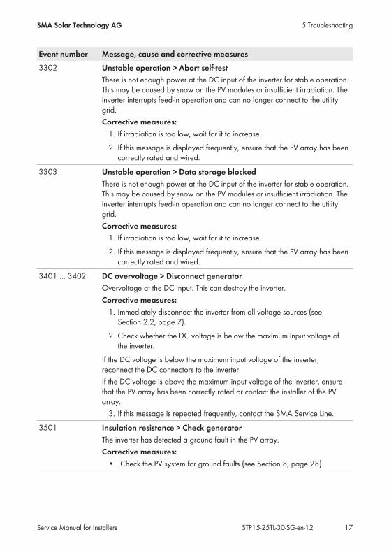
Event number Message, cause and corrective measures3302 Unstable operation > Abort self-test
There is not enough power at the DC input of the inverter for stable operation.This may be caused by snow on the PV modules or insufficient irradiation. Theinverter interrupts feed-in operation and can no longer connect to the utilitygrid.Corrective measures:
1. If irradiation is too low, wait for it to increase.2. If this message is displayed frequently, ensure that the PV array has been
correctly rated and wired.
3303 Unstable operation > Data storage blockedThere is not enough power at the DC input of the inverter for stable operation.This may be caused by snow on the PV modules or insufficient irradiation. Theinverter interrupts feed-in operation and can no longer connect to the utilitygrid.Corrective measures:
1. If irradiation is too low, wait for it to increase.2. If this message is displayed frequently, ensure that the PV array has been
correctly rated and wired.
3401 … 3402 DC overvoltage > Disconnect generatorOvervoltage at the DC input. This can destroy the inverter.Corrective measures:
1. Immediately disconnect the inverter from all voltage sources (seeSection 2.2, page 7).
2. Check whether the DC voltage is below the maximum input voltage ofthe inverter.
If the DC voltage is below the maximum input voltage of the inverter,reconnect the DC connectors to the inverter.If the DC voltage is above the maximum input voltage of the inverter, ensurethat the PV array has been correctly rated or contact the installer of the PVarray.
3. If this message is repeated frequently, contact the SMA Service Line.
3501 Insulation resistance > Check generatorThe inverter has detected a ground fault in the PV array.Corrective measures:
• Check the PV system for ground faults (see Section 8, page 28).
5 TroubleshootingSMA Solar Technology AG
Service Manual for Installers 17STP15-25TL-30-SG-en-12

Event number Message, cause and corrective measures3601 High discharge curr. > Check generator
The leakage currents of the inverter and the PV array are too high. There is aground fault, a residual current or a malfunction.The inverter interrupts feed-in operation immediately after exceeding a thresh-old and then automatically reconnects to the utility grid. If this process hap-pens five times a day, the inverter disconnects from the utility grid and termi-nates feed-in.Corrective measures:
• Check the PV system for ground faults (see Section 8, page 28).
3701 Resid.curr.too.high > Check generatorThe inverter has detected a residual current due to temporary grounding of thePV array.Corrective measures:
• Check the PV system for ground faults (see Section 8, page 28).
3801 … 3802 DC overcurrent > Check generatorOvercurrent at the DC input. The inverter briefly interrupts feed-in operation.Corrective measures:
• If this message is displayed frequently, ensure that the PV array hasbeen correctly rated and wired.
3901 … 3902 Waiting for DC start conditions > Start cond. not metThe feed-in conditions for the utility grid are not yet fulfilled.Corrective measures:
1. If irradiation is too low, wait for it to increase.2. If this message is displayed frequently in the morning, increase the
voltage limit for starting grid feed-in. Change the parameter Minimumvoltage input or A.VStr, B.VStr.
3. If this message is displayed frequently with medium irradiation, ensurethat the PV array is correctly rated.
6001 … 6438 Self diagnosis > Interference deviceThe cause must be determined by the SMA Service Line.Corrective measures:
• Contact the SMA Service Line.
6501 … 6511 Self diagnosis > Interference deviceThe inverter has switched off due to excessive temperature.Corrective measures:
1. Clean the fans (see Section 6, page 23).2. Ensure that the inverter has sufficient ventilation.
5 Troubleshooting SMA Solar Technology AG
Service Manual for InstallersSTP15-25TL-30-SG-en-1218

Event number Message, cause and corrective measures6512 Minimum operating temperature not reached
The inverter will only recommence grid feed-in once the temperature hasreached at least −25°C.
6603 … 6604 Self-diagnosis > OverloadThe cause must be determined by the SMA Service Line.Corrective measures:
• Contact the SMA Service Line.
6606 Interference deviceThe cause must be determined by the SMA Service Line.Corrective measures:
• Contact the SMA Service Line.
6701 … 6702 Communication disturbedThe cause must be determined by the SMA Service Line.Corrective measures:
• Contact the SMA Service Line.
6801 … 6802 Self-diagnosis > Input A defectiveThe cause must be determined by the SMA Service Line.Corrective measures:
• Contact the SMA Service Line.
6901 … 6902 Self-diagnosis > Input B defectiveThe cause must be determined by the SMA Service Line.Corrective measures:
• Contact the SMA Service Line.
7001 … 7002 Sensor fault fan permanently onThe cause must be determined by the SMA Service Line.Corrective measures:
• Contact the SMA Service Line.
7101 SD card defectiveThe SD memory card is not formatted.Corrective measures:
• Re-format the SD memory card.• Re-save the files to the SD memory card.
5 TroubleshootingSMA Solar Technology AG
Service Manual for Installers 19STP15-25TL-30-SG-en-12
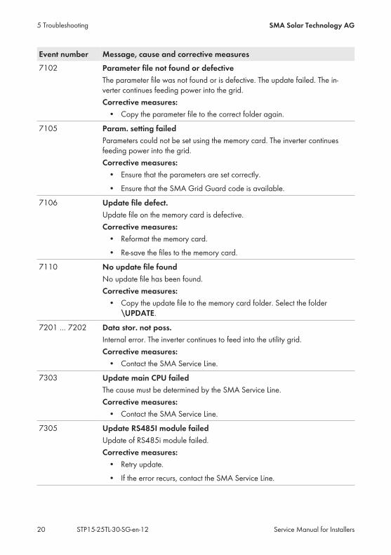
Event number Message, cause and corrective measures7102 Parameter file not found or defective
The parameter file was not found or is defective. The update failed. The in-verter continues feeding power into the grid.Corrective measures:
• Copy the parameter file to the correct folder again.
7105 Param. setting failedParameters could not be set using the memory card. The inverter continuesfeeding power into the grid.Corrective measures:
• Ensure that the parameters are set correctly.• Ensure that the SMA Grid Guard code is available.
7106 Update file defect.Update file on the memory card is defective.Corrective measures:
• Reformat the memory card.• Re-save the files to the memory card.
7110 No update file foundNo update file has been found.Corrective measures:
• Copy the update file to the memory card folder. Select the folder\UPDATE.
7201 … 7202 Data stor. not poss.Internal error. The inverter continues to feed into the utility grid.Corrective measures:
• Contact the SMA Service Line.
7303 Update main CPU failedThe cause must be determined by the SMA Service Line.Corrective measures:
• Contact the SMA Service Line.
7305 Update RS485I module failedUpdate of RS485i module failed.Corrective measures:
• Retry update.• If the error recurs, contact the SMA Service Line.
5 Troubleshooting SMA Solar Technology AG
Service Manual for InstallersSTP15-25TL-30-SG-en-1220
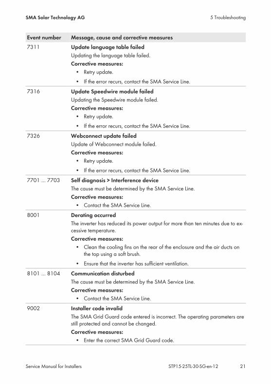
Event number Message, cause and corrective measures7311 Update language table failed
Updating the language table failed.Corrective measures:
• Retry update.• If the error recurs, contact the SMA Service Line.
7316 Update Speedwire module failedUpdating the Speedwire module failed.Corrective measures:
• Retry update.• If the error recurs, contact the SMA Service Line.
7326 Webconnect update failedUpdate of Webconnect module failed.Corrective measures:
• Retry update.• If the error recurs, contact the SMA Service Line.
7701 … 7703 Self diagnosis > Interference deviceThe cause must be determined by the SMA Service Line.Corrective measures:
• Contact the SMA Service Line.
8001 Derating occurredThe inverter has reduced its power output for more than ten minutes due to ex-cessive temperature.Corrective measures:
• Clean the cooling fins on the rear of the enclosure and the air ducts onthe top using a soft brush.
• Ensure that the inverter has sufficient ventilation.
8101 … 8104 Communication disturbedThe cause must be determined by the SMA Service Line.Corrective measures:
• Contact the SMA Service Line.
9002 Installer code invalidThe SMA Grid Guard code entered is incorrect. The operating parameters arestill protected and cannot be changed.Corrective measures:
• Enter the correct SMA Grid Guard code.
5 TroubleshootingSMA Solar Technology AG
Service Manual for Installers 21STP15-25TL-30-SG-en-12

Event number Message, cause and corrective measures9003 Grid parameter locked
The parameters are now locked. You cannot change the parameters.Corrective measures:
• Unlock the parameters with the SMA Grid Guard code.
9005 Changing of grid parameters not possible > Ensure DC supply.PV power is too low for setting the country data set. As soon as sufficient irra-diation is available, the inverter assumes the setting automatically.
5 Troubleshooting SMA Solar Technology AG
Service Manual for InstallersSTP15-25TL-30-SG-en-1222
6 Cleaning the Fans
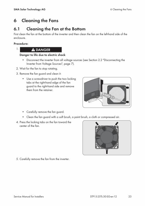
6.1 Cleaning the Fan at the BottomFirst clean the fan at the bottom of the inverter and then clean the fan on the left-hand side of theenclosure.
Procedure:1.
Danger to life due to electric shock• Disconnect the inverter from all voltage sources (see Section 2.2 "Disconnecting the
Inverter from Voltage Sources", page 7).2. Wait for the fan to stop rotating.3. Remove the fan guard and clean it:
• Use a screwdriver to push the two lockingtabs at the right-hand edge of the fanguard to the right-hand side and removethem from the retainer.
• Carefully remove the fan guard.• Clean the fan guard with a soft brush, a paint brush, a cloth or compressed air.
4. Press the locking tabs on the fan toward thecenter of the fan.
5. Carefully remove the fan from the inverter.
6 Cleaning the FansSMA Solar Technology AG
Service Manual for Installers 23STP15-25TL-30-SG-en-12
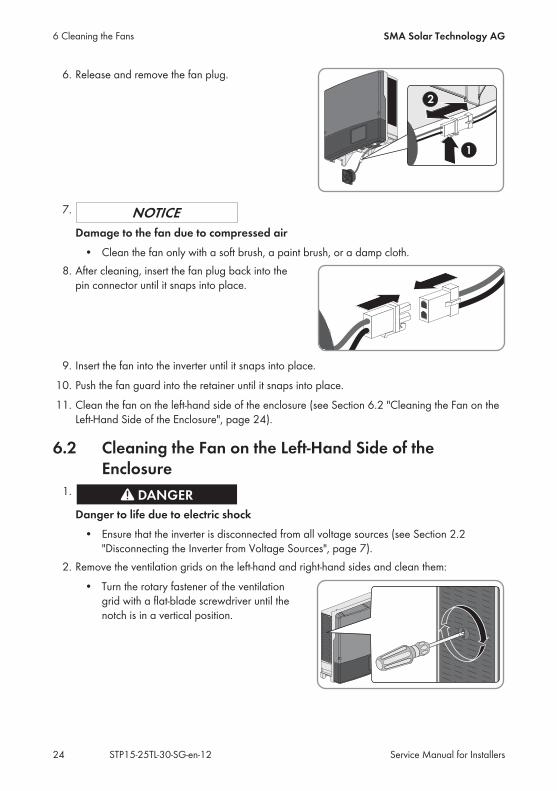
6. Release and remove the fan plug.
7.
Damage to the fan due to compressed air• Clean the fan only with a soft brush, a paint brush, or a damp cloth.
8. After cleaning, insert the fan plug back into thepin connector until it snaps into place.
9. Insert the fan into the inverter until it snaps into place.10. Push the fan guard into the retainer until it snaps into place.11. Clean the fan on the left-hand side of the enclosure (see Section 6.2 "Cleaning the Fan on the
Left-Hand Side of the Enclosure", page 24).
6.2 Cleaning the Fan on the Left-Hand Side of theEnclosure
1.
Danger to life due to electric shock• Ensure that the inverter is disconnected from all voltage sources (see Section 2.2
"Disconnecting the Inverter from Voltage Sources", page 7).2. Remove the ventilation grids on the left-hand and right-hand sides and clean them:
• Turn the rotary fastener of the ventilationgrid with a flat-blade screwdriver until thenotch is in a vertical position.
6 Cleaning the Fans SMA Solar Technology AG
Service Manual for InstallersSTP15-25TL-30-SG-en-1224
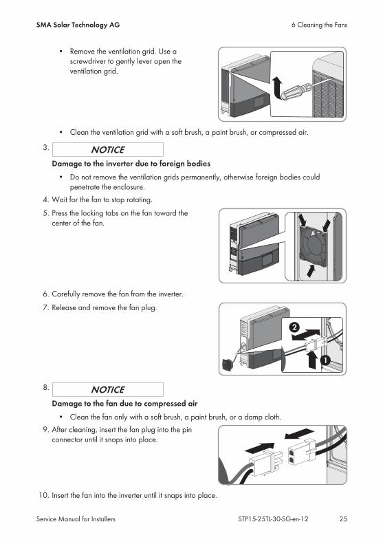
• Remove the ventilation grid. Use ascrewdriver to gently lever open theventilation grid.
• Clean the ventilation grid with a soft brush, a paint brush, or compressed air.
3.
Damage to the inverter due to foreign bodies• Do not remove the ventilation grids permanently, otherwise foreign bodies could
penetrate the enclosure.4. Wait for the fan to stop rotating.5. Press the locking tabs on the fan toward the
center of the fan.
6. Carefully remove the fan from the inverter.7. Release and remove the fan plug.
8.
Damage to the fan due to compressed air• Clean the fan only with a soft brush, a paint brush, or a damp cloth.
9. After cleaning, insert the fan plug into the pinconnector until it snaps into place.
10. Insert the fan into the inverter until it snaps into place.
6 Cleaning the FansSMA Solar Technology AG
Service Manual for Installers 25STP15-25TL-30-SG-en-12
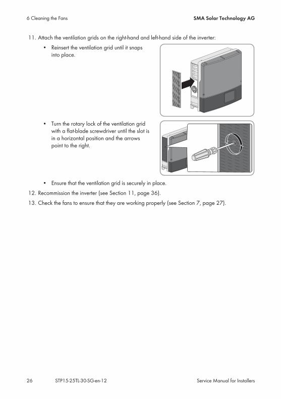
11. Attach the ventilation grids on the right-hand and left-hand side of the inverter:• Reinsert the ventilation grid until it snaps
into place.
• Turn the rotary lock of the ventilation gridwith a flat-blade screwdriver until the slot isin a horizontal position and the arrowspoint to the right.
• Ensure that the ventilation grid is securely in place.12. Recommission the inverter (see Section 11, page 36).13. Check the fans to ensure that they are working properly (see Section 7, page 27).
6 Cleaning the Fans SMA Solar Technology AG
Service Manual for InstallersSTP15-25TL-30-SG-en-1226
7 Checking the Function of the FansYou can check the function of the fans by setting a parameter.The basic procedure for changing operating parameters is described in the manual of the inverteror the communication product (see the operating manual of the inverter or communication product).
Procedure:1. Select the parameter Fan test or FanTst and set to On.2. Save settings.3. Check whether air is being drawn in through the bottom and is coming out of the upper
ventilation grids and whether the fans are making any unusual noises.If no air is being drawn in through the bottom, no air is coming out of the ventilation grids, orthe fans are making unusual noises, then the fans were presumably installed improperly.Check whether the fans have been installed correctly.If the fans were installed correctly, contact Service (see Section 15, page 46).
4. Select the parameter Fan test or FanTst and set to Off.5. Save settings.
7 Checking the Function of the FansSMA Solar Technology AG
Service Manual for Installers 27STP15-25TL-30-SG-en-12
8 Checking the PV System for Ground FaultsIf the inverter displays the event numbers 3501, 3601 or 3701, there could be a ground fault. Theelectrical insulation from the PV system to ground is defective or insufficient.
Danger to life due to electric shockIn the event of a ground fault, high voltages can be present.
• Touch the cables of the PV array on the insulation only.• Do not touch any parts of the substructure or frame of the PV array.• Do not connect PV strings with ground faults to the inverter.
Destruction of the measuring device due to overvoltage• Only use measuring devices with a DC input voltage range of 1000 V or higher.
Procedure:In order to check the PV system for ground faults, perform the following actions in the prescribedorder. The exact procedure is described in the following sections.
• Check the PV system for ground faults by measuring the voltage.• If the voltage measurement was not successful, check the PV system via insulation resistance
measurement for ground faults.
Test by Measuring the VoltageProceed as follows to check each string in the PV system for ground faults.
Procedure:1.
Danger to life due to high voltages• Disconnect the inverter from all voltage sources (see Section 2.2, page 7).
2. Measure the voltages:• Measure the voltage between the positive terminal and the ground potential (PE).• Measure the voltage between the negative terminal and the ground potential (PE).• Measure the voltage between the positive and negative terminals.
If the following results are present at the same time, there is a ground fault in the PVsystem:☑ All measured voltages are stable.☑ The sum of the two voltages to ground potential is approximately equal to the
voltage between the positive and negative terminals.
8 Checking the PV System for Ground Faults SMA Solar Technology AG
Service Manual for InstallersSTP15-25TL-30-SG-en-1228

• If a ground fault is present, determine the location of the ground fault via the ratio of thetwo measured voltages and eliminate the ground fault.
Example: Location of the ground faultThe example shows a ground fault between the second and third PV module.
3. If a definite ground fault cannot be measured and the message is still displayed, measure theinsulation resistance.
4. Reconnect the strings without ground faults to the inverter and recommission the inverter.
Test by Measuring the Insulation ResistanceIf the voltage measurement does not provide sufficient evidence of a ground fault, the insulationresistance measurement can provide more exact results.
Figure 1: Schematic diagram of the measurement
8 Checking the PV System for Ground FaultsSMA Solar Technology AG
Service Manual for Installers 29STP15-25TL-30-SG-en-12
Calculating the insulation resistanceThe expected total resistance of the PV system or of an individual string can be calculatedusing the following formula:
total
The exact insulation resistance of a PV module can be obtained from the module manufactureror the datasheet.For the resistance of a PV module an average value can be assumed: for thin-film PV modulesapproximately 40 MOhm and for polycrystalline and monocrystalline PV modulesapproximately 50 MOhm per PV module (for further information on calculating the insulationresistance see the Technical Information "Insulation Resistance (Riso) of Non-GalvanicallyIsolated PV Systems" at www.SMA-Solar.com).
Required devices:☐ Suitable device for safe disconnection and short-circuiting☐ Measuring device for insulation resistance
Device required for safe disconnection and short-circuiting of the PV arrayThe insulation resistance can only be measured with a suitable device for safe disconnectionand short-circuiting of the PV array. If no suitable device is available, the insulationmeasurement must not be carried out.
Procedure:1. Calculate the expected insulation resistance per string.
2.
Danger to life due to high voltages• Disconnect the inverter from all voltage sources (see Section 2.2, page 7).
3. Install the short circuit device.4. Connect the measuring device for insulation resistance.5. Short-circuit the first string.6. Set the test voltage. The test voltage should be as close as possible to the maximum system
voltage of the PV modules but must not exceed it (see datasheet of the PV modules).7. Measure the insulation resistance.8. Eliminate the short circuit.9. Measure the remaining strings in the same manner.
☑ If the insulation resistance of a string deviates considerably from the theoreticallycalculated value, there is a ground fault present in that string.
10. Reconnect to the inverter only those strings from which the ground fault has been eliminated.11. Reconnect all other strings to the inverter.
8 Checking the PV System for Ground Faults SMA Solar Technology AG
Service Manual for InstallersSTP15-25TL-30-SG-en-1230
12. Recommission the inverter.13. If the inverter still displays an insulation error, contact the Service (see Section 15 "Contact",
page 46). The PV modules might not be suitable for the inverter in the present quantity.
8 Checking the PV System for Ground FaultsSMA Solar Technology AG
Service Manual for Installers 31STP15-25TL-30-SG-en-12

9 Checking the Function of the Surge ArrestersSurge arresters are wearing parts. Their functionality diminishes with age or following repeatedexposure to overvoltage. It is therefore possible for the surge arresters to lose their protectivefunction over time.Check the function of the surge arresters as described in the following.
Procedure:1.
Danger to life due to electric shock• Disconnect the inverter from all voltage sources (see Section 2.2, page 7).• Wait 20 minutes before removing the DC protective cover.
2. Release the screws on the DC protective coverusing an Allen key (AF 3), lift the DC protectivecover upwards from below and remove it.
3. Check whether one of the surge arresters isdefective.
If no stripe is visible next to the type designation in the inspection window of the surge arrester,the surge arrester is in good condition.If a red stripe is visible next to the type designation in the inspection window of the surgearrester, the surge arrester is defective.
• Order new surge arresters.• If new surge arresters are available, replace all surge arresters (see Section 10,
page 34).
9 Checking the Function of the Surge Arresters SMA Solar Technology AG
Service Manual for InstallersSTP15-25TL-30-SG-en-1232

4. Tighten all four screws on the DC protectivecover with an Allen key (AF 3) in the sequence 1to 4 (torque: 3 Nm ± 0.3 Nm).
5. Recommission the inverter (see Section 11 "Recommissioning the Inverter", page 36).
9 Checking the Function of the Surge ArrestersSMA Solar Technology AG
Service Manual for Installers 33STP15-25TL-30-SG-en-12
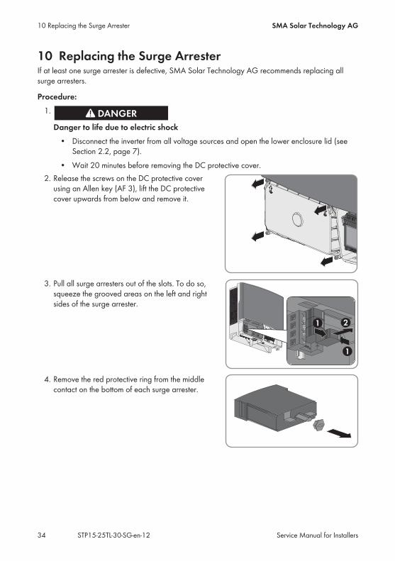
10 Replacing the Surge ArresterIf at least one surge arrester is defective, SMA Solar Technology AG recommends replacing allsurge arresters.
Procedure:1.
Danger to life due to electric shock• Disconnect the inverter from all voltage sources and open the lower enclosure lid (see
Section 2.2, page 7).• Wait 20 minutes before removing the DC protective cover.
2. Release the screws on the DC protective coverusing an Allen key (AF 3), lift the DC protectivecover upwards from below and remove it.
3. Pull all surge arresters out of the slots. To do so,squeeze the grooved areas on the left and rightsides of the surge arrester.
4. Remove the red protective ring from the middlecontact on the bottom of each surge arrester.
10 Replacing the Surge Arrester SMA Solar Technology AG
Service Manual for InstallersSTP15-25TL-30-SG-en-1234

5. Plug the new surge arresters into the designatedslots until they lock into place with the lockingtabs. The inspection window on each surgearrester must face to the right.
6. Ensure that each surge arrester is securely inserted into its slot.7. Tighten all four screws on the DC protective
cover with an Allen key (AF 3) in the sequence 1to 4 (torque: 3 Nm ± 0.3 Nm).
10 Replacing the Surge ArresterSMA Solar Technology AG
Service Manual for Installers 35STP15-25TL-30-SG-en-12
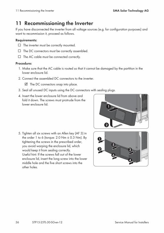
11 Recommissioning the InverterIf you have disconnected the inverter from all voltage sources (e.g. for configuration purposes) andwant to recommission it, proceed as follows.
Requirements:☐ The inverter must be correctly mounted.☐ The DC connectors must be correctly assembled.☐ The AC cable must be connected correctly.
Procedure:1. Make sure that the AC cable is routed so that it cannot be damaged by the partition in the
lower enclosure lid.2. Connect the assembled DC connectors to the inverter.
☑ The DC connectors snap into place.3. Seal all unused DC inputs using the DC connectors with sealing plugs.4. Insert the lower enclosure lid from above and
fold it down. The screws must protrude from thelower enclosure lid.
5. Tighten all six screws with an Allen key (AF 3) inthe order 1 to 6 (torque: 2.0 Nm ± 0.3 Nm). Bytightening the screws in the prescribed order,you avoid warping the enclosure lid, whichwould keep it from sealing correctly.Useful hint: If the screws fall out of the lowerenclosure lid, insert the long screw into the lowermiddle hole and the five short screws into theother holes.
11 Recommissioning the Inverter SMA Solar Technology AG
Service Manual for InstallersSTP15-25TL-30-SG-en-1236
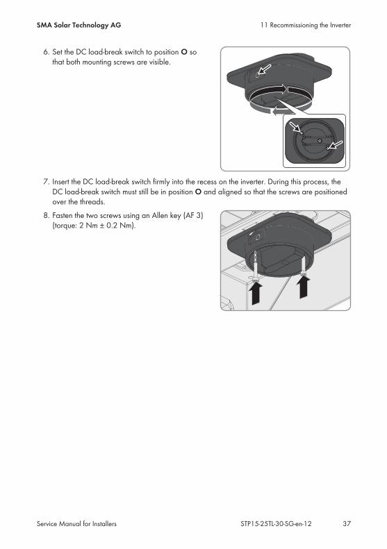
6. Set the DC load-break switch to position O sothat both mounting screws are visible.
7. Insert the DC load-break switch firmly into the recess on the inverter. During this process, theDC load-break switch must still be in position O and aligned so that the screws are positionedover the threads.
8. Fasten the two screws using an Allen key (AF 3)(torque: 2 Nm ± 0.2 Nm).
11 Recommissioning the InverterSMA Solar Technology AG
Service Manual for Installers 37STP15-25TL-30-SG-en-12
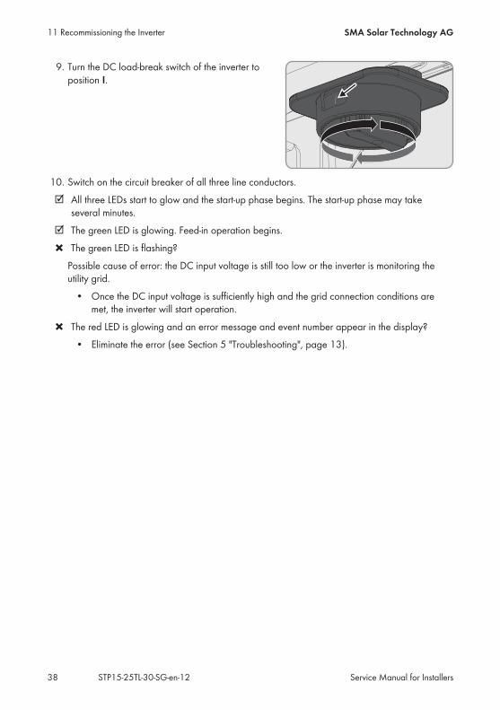
9. Turn the DC load-break switch of the inverter toposition I.
10. Switch on the circuit breaker of all three line conductors.☑ All three LEDs start to glow and the start-up phase begins. The start-up phase may take
several minutes.☑ The green LED is glowing. Feed-in operation begins.✖ The green LED is flashing?
Possible cause of error: the DC input voltage is still too low or the inverter is monitoring theutility grid.
• Once the DC input voltage is sufficiently high and the grid connection conditions aremet, the inverter will start operation.
✖ The red LED is glowing and an error message and event number appear in the display?• Eliminate the error (see Section 5 "Troubleshooting", page 13).
11 Recommissioning the Inverter SMA Solar Technology AG
Service Manual for InstallersSTP15-25TL-30-SG-en-1238

12 Procedure for Receiving a Replacement DeviceUnder fault conditions, the inverter may need to be replaced. If this is the case, you will receive areplacement device from SMA Solar Technology AG. If you received a replacement device,replace the defective inverter with the replacement device as described in this section.
Procedure:• Decommission the defective inverter.• Commission the replacement device.• Ship the defective inverter.
Decommissioning the Defective Inverter
Risk of injury when lifting the inverter, or if it is droppedThe inverter weighs 61 kg. There is risk of injury if the inverter is lifted incorrectly or dropped whilebeing transported or when attaching it to or removing it from the wall mounting bracket.
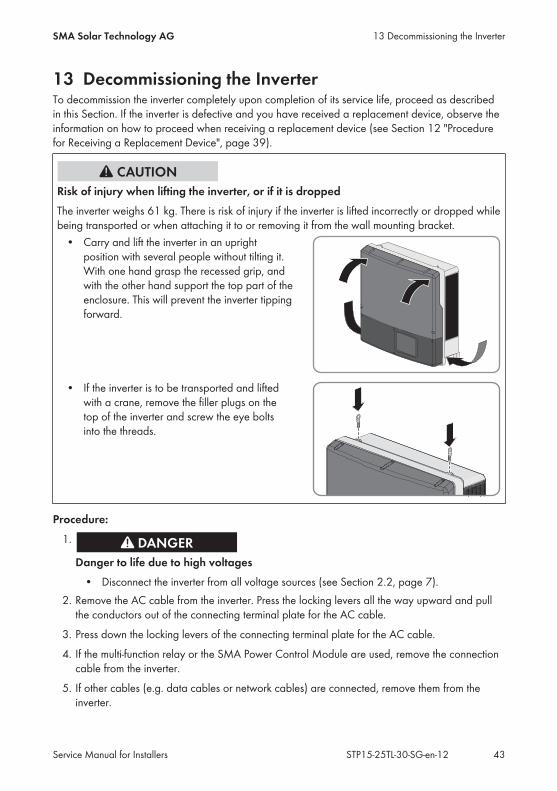
• Carry and lift the inverter in an uprightposition with several people without tilting it.With one hand grasp the recessed grip, andwith the other hand support the top part of theenclosure. This will prevent the inverter tippingforward.
• If the inverter is to be transported and liftedwith a crane, remove the filler plugs on thetop of the inverter and screw the eye boltsinto the threads.
1.
Danger to life due to electric shock• Disconnect the inverter from all voltage sources (see Section 2.2, page 7).
2. Remove the AC cable from the inverter. Press the locking levers all the way upward and pullthe conductors out of the connecting terminal plate for the AC cable.
3. Press down the locking levers of the connecting terminal plate for the AC cable.4. Remove the cable for the additional grounding from the grounding terminal, if necessary.
12 Procedure for Receiving a Replacement DeviceSMA Solar Technology AG
Service Manual for Installers 39STP15-25TL-30-SG-en-12

5. If the multi-function relay or the SMA Power Control Module are used, remove the connectioncable from the inverter.
6. If other cables (e.g. data cables or network cables) are connected, remove them from theinverter.
7. Remove any installed interfaces from the inverter (see the manual for the communicationinterface).
8. If surge arresters are present, remove the surge arresters from the defective inverter (seeSection 10, page 34).
9. Close all enclosure openings.10. Keep the DC load-break switch in a safe place as the replacement device will be delivered
without the DC load-break switch.
11.
Risk of burns due to hot enclosure parts• Wait 30 minutes before disassembling the inverter. This will allow the enclosure to cool
down and thus prevent burn injuries.12. Remove the inverter by lifting it vertically up and off the wall mounting bracket.
Commissioning the Replacement Device
Damage to seals on the enclosure lids in subfreezing conditionsIf you open the upper and lower enclosure lids when temperatures are below freezing, theenclosure seals can be damaged. This can lead to moisture entering the inverter.
• Do not open the inverter at ambient temperatures lower than -5°C.• If a layer of ice has formed on the seal of the lid when temperatures are below freezing,
remove it prior to opening the enclosure lids of the inverter (e.g. by melting the ice withwarm air). Observe the applicable safety regulations.
Damage to the inverter due to moisture and dust intrusionDust or moisture intrusion can damage the inverter and impair its functionality.
• Close all enclosure openings of the inverter tightly.• Never open the inverter when it is raining or snowing, or the humidity is over 95%.
12 Procedure for Receiving a Replacement Device SMA Solar Technology AG
Service Manual for InstallersSTP15-25TL-30-SG-en-1240
Damage to the inverter due to electrostatic dischargeTouching electronic components can cause damage to or destroy the inverter throughelectrostatic discharge.
• Ground yourself before touching any component.
1. Mount the replacement device and make the electrical connections (see the operating manualof the inverter).
2. If needed, install interfaces in the replacement device and connect the interfaces (see theinterface manual).
3. If needed, install a surge arrester in the replacement device (see Section 4 "Retrofitting theSurge Arrester Type II", page 12).
4. If there is a label with "transport lid" affixed to the upper lid of the replacement device, replacethe upper enclosure lid of the replacement device with the upper enclosure lid of the defectiveinverter.
Danger to life due to high voltagesWait 20 minutes before removing the upper enclosure lid to allow residual voltages to discharge.
• Loosen the screws of the upper enclosure lid using an Allen key (AF 4) and remove theenclosure lid.
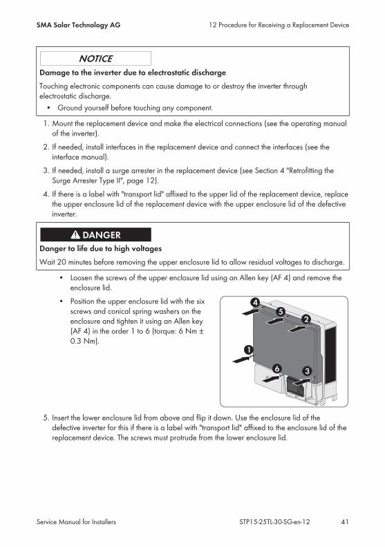
• Position the upper enclosure lid with the sixscrews and conical spring washers on theenclosure and tighten it using an Allen key(AF 4) in the order 1 to 6 (torque: 6 Nm ±0.3 Nm).
5. Insert the lower enclosure lid from above and flip it down. Use the enclosure lid of thedefective inverter for this if there is a label with "transport lid" affixed to the enclosure lid of thereplacement device. The screws must protrude from the lower enclosure lid.
12 Procedure for Receiving a Replacement DeviceSMA Solar Technology AG
Service Manual for Installers 41STP15-25TL-30-SG-en-12
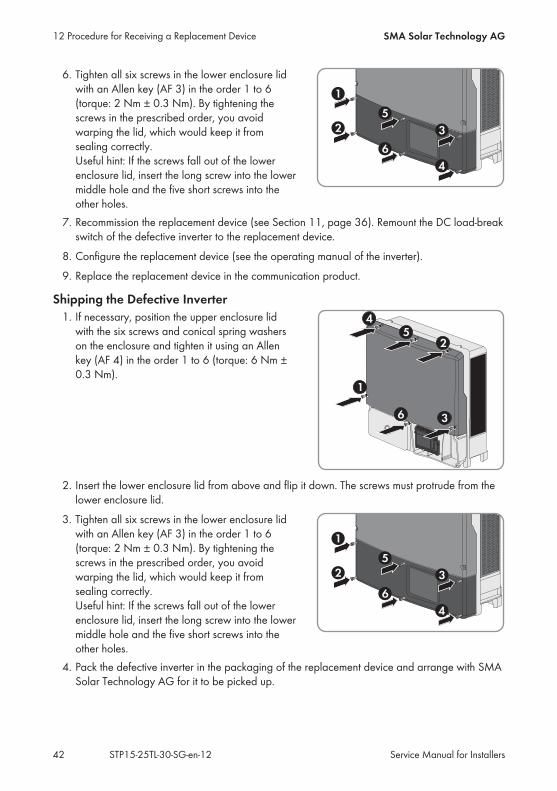
6. Tighten all six screws in the lower enclosure lidwith an Allen key (AF 3) in the order 1 to 6(torque: 2 Nm ± 0.3 Nm). By tightening thescrews in the prescribed order, you avoidwarping the lid, which would keep it fromsealing correctly. Useful hint: If the screws fall out of the lowerenclosure lid, insert the long screw into the lowermiddle hole and the five short screws into theother holes.
7. Recommission the replacement device (see Section 11, page 36). Remount the DC load-breakswitch of the defective inverter to the replacement device.
8. Configure the replacement device (see the operating manual of the inverter).9. Replace the replacement device in the communication product.
Shipping the Defective Inverter1. If necessary, position the upper enclosure lid
with the six screws and conical spring washerson the enclosure and tighten it using an Allenkey (AF 4) in the order 1 to 6 (torque: 6 Nm ±0.3 Nm).
2. Insert the lower enclosure lid from above and flip it down. The screws must protrude from thelower enclosure lid.
3. Tighten all six screws in the lower enclosure lidwith an Allen key (AF 3) in the order 1 to 6(torque: 2 Nm ± 0.3 Nm). By tightening thescrews in the prescribed order, you avoidwarping the lid, which would keep it fromsealing correctly.Useful hint: If the screws fall out of the lowerenclosure lid, insert the long screw into the lowermiddle hole and the five short screws into theother holes.
4. Pack the defective inverter in the packaging of the replacement device and arrange with SMASolar Technology AG for it to be picked up.
12 Procedure for Receiving a Replacement Device SMA Solar Technology AG
Service Manual for InstallersSTP15-25TL-30-SG-en-1242
13 Decommissioning the InverterTo decommission the inverter completely upon completion of its service life, proceed as describedin this Section. If the inverter is defective and you have received a replacement device, observe theinformation on how to proceed when receiving a replacement device (see Section 12 "Procedurefor Receiving a Replacement Device", page 39).
Risk of injury when lifting the inverter, or if it is droppedThe inverter weighs 61 kg. There is risk of injury if the inverter is lifted incorrectly or dropped whilebeing transported or when attaching it to or removing it from the wall mounting bracket.
• Carry and lift the inverter in an uprightposition with several people without tilting it.With one hand grasp the recessed grip, andwith the other hand support the top part of theenclosure. This will prevent the inverter tippingforward.
• If the inverter is to be transported and liftedwith a crane, remove the filler plugs on thetop of the inverter and screw the eye boltsinto the threads.
Procedure:1.
Danger to life due to high voltages• Disconnect the inverter from all voltage sources (see Section 2.2, page 7).
2. Remove the AC cable from the inverter. Press the locking levers all the way upward and pullthe conductors out of the connecting terminal plate for the AC cable.
3. Press down the locking levers of the connecting terminal plate for the AC cable.4. If the multi-function relay or the SMA Power Control Module are used, remove the connection
cable from the inverter.5. If other cables (e.g. data cables or network cables) are connected, remove them from the
inverter.
13 Decommissioning the InverterSMA Solar Technology AG
Service Manual for Installers 43STP15-25TL-30-SG-en-12
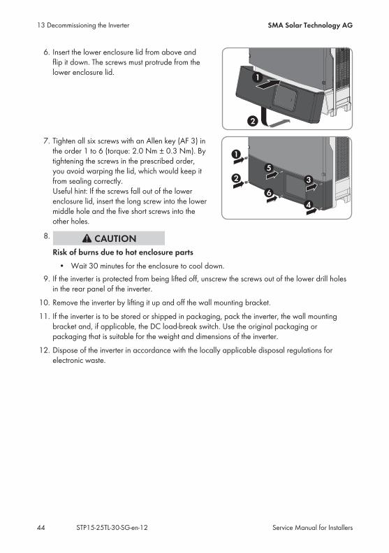
6. Insert the lower enclosure lid from above andflip it down. The screws must protrude from thelower enclosure lid.
7. Tighten all six screws with an Allen key (AF 3) inthe order 1 to 6 (torque: 2.0 Nm ± 0.3 Nm). Bytightening the screws in the prescribed order,you avoid warping the lid, which would keep itfrom sealing correctly.Useful hint: If the screws fall out of the lowerenclosure lid, insert the long screw into the lowermiddle hole and the five short screws into theother holes.
8.
Risk of burns due to hot enclosure parts• Wait 30 minutes for the enclosure to cool down.
9. If the inverter is protected from being lifted off, unscrew the screws out of the lower drill holesin the rear panel of the inverter.
10. Remove the inverter by lifting it up and off the wall mounting bracket.11. If the inverter is to be stored or shipped in packaging, pack the inverter, the wall mounting
bracket and, if applicable, the DC load-break switch. Use the original packaging orpackaging that is suitable for the weight and dimensions of the inverter.
12. Dispose of the inverter in accordance with the locally applicable disposal regulations forelectronic waste.
13 Decommissioning the Inverter SMA Solar Technology AG
Service Manual for InstallersSTP15-25TL-30-SG-en-1244
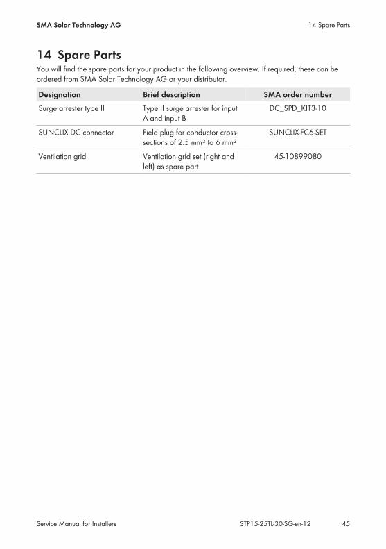
14 Spare PartsYou will find the spare parts for your product in the following overview. If required, these can beordered from SMA Solar Technology AG or your distributor.
Designation Brief description SMA order numberSurge arrester type II Type II surge arrester for input
A and input BDC_SPD_KIT3-10
SUNCLIX DC connector Field plug for conductor cross-sections of 2.5 mm² to 6 mm²
SUNCLIX-FC6-SET
Ventilation grid Ventilation grid set (right andleft) as spare part
45-10899080
14 Spare PartsSMA Solar Technology AG
Service Manual for Installers 45STP15-25TL-30-SG-en-12
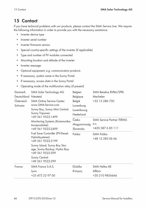
15 ContactIf you have technical problems with our products, please contact the SMA Service Line. We requirethe following information in order to provide you with the necessary assistance:
• Inverter device type• Inverter serial number• Inverter firmware version• Special country-specific settings of the inverter (if applicable)• Type and number of PV modules connected• Mounting location and altitude of the inverter• Inverter message• Optional equipment, e.g. communication products• If necessary, system name in the Sunny Portal• If necessary, access data in the Sunny Portal• Operating mode of the multifunction relay (if present)
DanmarkDeutschlandÖsterreichSchweiz
SMA Solar Technology AGNiestetalSMA Online Service Center:www.SMA-Service.comSunny Boy, Sunny Mini Central,Sunny Tripower:+49 561 9522‑1499Monitoring Systems (Kommunika-tionsprodukte):+49 561 9522‑2499Fuel Save Controller (PV-Diesel-Hybridsysteme):+49 561 9522-3199Sunny Island, Sunny Boy Stor-age, Sunny Backup, Hydro Boy:+49 561 9522-399Sunny Central:+49 561 9522-299
BelgienBelgiqueBelgiëLuxemburgLuxembourgNederland
SMA Benelux BVBA/SPRLMechelen+32 15 286 730
ČeskoMagyarországSlovensko
SMA Service Partner TERMSa.s.+420 387 6 85 111
Polska SMA Polska+48 12 283 06 66
France SMA France S.A.S.Lyon+33 472 22 97 00
ΕλλάδαΚύπρος
SMA Hellas AEΑθήνα+30 210 9856666
15 Contact SMA Solar Technology AG
Service Manual for InstallersSTP15-25TL-30-SG-en-1246

EspañaPortugal
SMA Ibérica Tecnología Solar,S.L.U.Barcelona+34 935 63 50 99
United King-dom
SMA Solar UK Ltd.Milton Keynes+44 1908 304899
BulgariaItaliaRomânia
SMA Italia S.r.l.Milano+39 02 8934-7299
United ArabEmirates
SMA Middle East LLCAbu Dhabi+971 2234 6177
India SMA Solar India Pvt. Ltd.Mumbai+91 22 61713888
SMA Solar (Thailand) Co., Ltd.
+66 2 670 6999
대한민국 SMA Technology Korea Co.,Ltd.서울+82-2-520-2666
South Africa SMA Solar Technology SouthAfrica Pty Ltd.Cape Town08600SUNNY (08600 78669)International: +27 (0)21 8260600
ArgentinaBrasilChilePerú
SMA South America SPASantiago+562 2820 2101
Australia SMA Australia Pty Ltd.SydneyToll free for Australia:1800 SMA AUS(1800 762 287)International: +61 2 9491 4200
Other countries International SMA Service LineNiestetal00800 SMA SERVICE(+800 762 7378423)
15 ContactSMA Solar Technology AG
Service Manual for Installers 47STP15-25TL-30-SG-en-12

www.SMA-Solar.com