service manual - university of virginia
TRANSCRIPT

SERVICE MANUAL
neoBLUE® mini System Service Manual P/N 051466E
Caution: Federal Law (U.S.) restricts this device to sale or use by or on the order of a physician (or properly licensed practitioner).
Natus is a registered trademark of Natus Medical Incorporated.
neoBLUE mini is a registered trademark of Natus Medical Incorporated.
Biliband is a registered trademark of Natus Medical Incorporated.
BiliBlanket is a registered trademark of Ohmeda.
Bili-meter is a registered trademark of Olympic Medical.
© 2009 Natus Medical Incorporated. All rights reserved.
This manual may not be reprinted or copied in whole or in part without written consent from Natus Medical Incorporated. The content of this manual may change without notice.
Natus Medical Incorporated 5900 First Avenue South Seattle, WA 98108 USA Telephone +1 650 802 0400 Fax +1 650 802 0401
Technical Service +1 800 303 0306 Technical Service Fax +1 650 802 8680 E-mail: [email protected] Customer Service +1 800 303 0306 Customer Service Fax +1 650 802 6620 E-mail: [email protected]
International Support - Please contact your local Distributor. Distributor locations can be found at www.natus.com
EU Representative Natus Europe GmbH Bärmannstrasse 38 D-81245 München Germany
neoBLUE® mini System Service Manual P/N 051466E

CONTENTS 1 Product Description 2 Routine Maintenance Procedures
2.1 Cleaning 2.1.1 Cleaning the Light Enclosure and Adjustable Arm 2.1.2 Cleaning the Interior of the Light Enclosure 2.2 Safety Testing 2.3 Performance Verification
2.3.1 Verifying General Performance 2.3.2 Adjusting Light Intensity
3 Troubleshooting the neoBLUE mini light
4 Repair Procedures
4.1 Removing the Light Lens 4.2 Removing the LED PCB 4.3 Removing the Current PCB 4.4 Removing the ON/Standby Switch 4.5 Removing the Light Enclosure from the Adjustable Arm 4.6 Removing the Pole Mount from the Adjustable Arm 4.7 Spare Parts List
5 Measuring the neoBLUE mini Light with a Radiometer
neoBLUE® mini System Service Manual P/N 051440E ii

C H A P T E R 1
PRODUCT DESCRIPTION The neoBLUEmini LED Phototherapy System consists of two components – the neoBLUE mini phototherapy light enclosure and the adjustable arm with pole mount.
1.1 Intended Use
The neoBLUE mini LED Phototherapy System is intended for the treatment of neonatal hyperbilirubinemia. The light can be used for infants in an open bed, incubator, bassinet, or radiant warmer.
1.2 Physical Characteristics
The neoBLUE mini device is a mobile phototherapy light that delivers a narrow band of high-intensity blue light via light emitting diodes (LEDs) to provide treatment for neonatal hyperbilirubinemia.
The light is housed in a lightweight plastic enclosure. The light can be positioned in multiple positions and used with a variety of patient enclosures such as open beds, incubators, bassinets, or radiant warmers.
The arm is designed to attach to poles with 0.75 to 1.5 inch (1.91 to 3.81 cm) diameters.
The light output is optimized to provide a peak intensity of 30-35 µW/cm2/nm. Blue LEDs emit light in the range of 400 – 550 nm (peak wavelength 450-470 nm). This range corresponds to the spectral absorption of light by bilirubin, and is thus considered to be the most effective for the degradation of bilirubin.
LEDs have minimal light output degradation over their lifetime with proper use. , The user can adjust the output of the LEDs using the potentiometer located on the side of the light enclosure. The light is expected to operate as specified for at least 3,000 hours.
1.3 Power Requirements and Accessories
The light runs off a 12V DC power supply. The power supply is mains-power operated. The power unit is supplied pre-attached to the pole mount portion of the arm. Grooves in the bottom of the arm hold the power cord for safe cable management.
neoBLUE® mini System Service Manual P/N 051466E 1

1.4 Safety Symbols
Warning! Be aware of the following symbols, which appear on the device.
Symbol Meaning
Type BF rated for patient-applied parts
Double-insulated (Class II)
On (mains power on)
Off (stand-by)
Attention, consult product documentation
Always protect the baby's eyes with eye patches or equivalent
Authorized European Representative
XXXX
Manufacture Date
Natus
Manufacturer
WEEE Directive (Waste from Electrical and Electronic Equipment Directive) Symbol – Product should not be disposed of in normal waste
neoBLUE® mini System Service Manual P/N 051466E 2
C H A P T E R 2
ROUTINE MAINTENANCE PROCEDURES This chapter includes procedures for routine maintenance of the neoBLUE mini device, hereafter called the UUT (Unit Under Test): 2.1 Cleaning
2.2 Safety Testing
2.3 Performance Verification These procedures must be performed after any of the following events and/or as prescribed by the institution’s maintenance schedule. Initial receipt of the UUT at the institution. Foreign material or liquid has been deposited on the UUT. UUT has been physically damaged or subjected to mechanical shock (i.e., being
dropped). UUT has been submitted for maintenance or scheduled performance verification. 2.1 Cleaning
Cleaning the UUT incorporates two different tasks: Cleaning the Light Enclosure and Adjustable Arm (Section 2.1.1) Cleaning the Interior of the Light Enclosure (Section 2.1.2)
Warning! Disconnect light from AC power before cleaning.
2.1.1 Cleaning the Light Enclosure and Adjustable Arm
Remove dust from the exterior of the device with a soft brush or soft cloth dampened with water. Sponge away remaining debris with a mild solution of detergent and water, a non-caustic commercial cleaner, or hospital disinfectant.
Clean the lens with a soft cloth dampened with water. If water alone is ineffective in removing fingerprints or other markings, use a mild solution of detergent and water, a non-caustic commercial cleaner, or hospital disinfectant.
Caution: Observe the following precautions:
Do not spray liquids directly onto the light, or allow them to seep into the interior. Do not use caustic or abrasive cleaners. Do not clean with alcohol, acetone, or other solvents. Never immerse the light or its component parts.
neoBLUE® mini System Service Manual P/N 051466E 3

2.1.2 Cleaning the Interior of the Light Enclosure
The cooling fan in the light enclosure will cause a buildup of dust on the components within. A Biomedical Equipment Technician should clean the inside of the light enclosure. Cleaning frequency should be determined by visual inspection of the interior. Frequency will vary depending on the environment.
2.2 Safety Testing
The safety tests meet the standards of, and are performed in accordance with, IEC 60601-1, Amendment 1, Amendment 2, and UL 2601-1, for instruments as Class 2 and TYPE BF and ANSI/NFPA Standard 99.
Note: The power supply has a functional earth for electromagnetic compliance.
Applicable tests for these standards are listed below (Tables 2.1 & 2.2). Technicians must be familiar with the standards applicable in the technician’s institution and country. Test equipment and its application must comply with the applicable standard.
TABLE 2.1 Power Cord Ground Integrity TABLE 2.2 Earth Leakage Current
Maximum Current Limits are listed below for each test and standard.
TABLE 2.1 Power Cord Ground Integrity
100 milliohms or less
TABLE 2.2 Earth Leakage Current AC Line Cord Polarity
Line Cord Neutral Cord IEC 60601-1 UL 2601-1 ANSI/NFPA 99
Normal Closed Closed 500 µA 300 µA Reversed Closed Closed 500 A 300 µA Normal Open Closed 1000 µA 500 µA Normal Closed Open 1000 µA 500 µA
2.3 Performance Verification This section discusses the tests necessary to verify UUT performance. Verifying General Performance (Section 2.3.1) Adjusting the Light Intensity (Section 2.3.2) All tests can be conducted without removing the UUT light enclosure. If the UUT fails to conform or cannot be adjusted to conform, repairs must be made to correct the problem before the instrument is returned to the user.
neoBLUE® mini System Service Manual P/N 051466E 4
Tools and Test Equipment Type
Radiometer* Natus neoBlue® Radiometer (P/N 53870) or equivalent* Potentiometer Adjustment Tool GC Electronics 8608 or equivalent Safety Glasses Amber “Blue Blockers” Work Pad Any non-abrasive non-static surface
* Note: If a different radiometer is used please refer to the Conversion Chart in chapter 5. If the meter is not listed, please contact Natus Technical Service before adjusting the LED intensity with the potentiometer. Intensity measurements are based on the patient being 12” from the panel lens of the UUT. Compensation may be performed if the patient application distance must be different than 12”. Adjusting the UUT light for a distance greater than 12” (increasing the potentiometer) will decrease expected LED panel life. Adjusting for a distance less than 12” (decreasing the potentiometer) will increase the LED panel life. See Chapter 1 for expected LED panel life.
2.3.1 Verifying General Performance
1. Switch the UUT to standby and disconnect the AC power cord.
2. These tests can be performed with the UUT on a roll stand or convenient mounting pole.
3. Attach the adjustable arm to the roll stand or mounting pole so the light enclosure can be examined. Verify that the air vents are not blocked.
4. Connect the AC power cord to the UUT and to an AC receptacle.
Warning! Operator Safety: Sensitive individuals may experience headache, nausea or mild vertigo if he/she stays too long in the illuminated area. Using the neoBLUE mini device in a well-lighted area or wearing glasses with yellow lenses can alleviate potential effects. Guard Dog Bones glasses (p/n 413BB) are recommended and are available online at www.safetyglasses.com or via phone at 1-800-870-6189.
5. Switch the UUT on. Verify that the ventilation fan is running and that the LED panel lights.
6. Examine panel geometry for unlit LEDs. Confirm that there are both blue and yellow LED components. The yellow components are uniformly spaced throughout the LED panel.
Note: The UUT can conform to specifications with some LEDs unlit. However, if a large number of LEDs are unlit, the UUT may not meet minimum values required during testing. LED intensity may need to be adjusted higher if many LEDs are unlit. This action will reduce LED life.
7. Switch the UUT to standby.
8. Position the UUT to suspend the light enclosure, facing down, 13.5” above a convenient work surface. Please recall that the specified adjustment distance is 12”. The additional 1.5” is to accommodate the radiometer sensor distance from the table surface.
Note: If a different radiometer is being used, its dimensions may change the 1.5” accommodation.
neoBLUE® mini System Service Manual P/N 051466E 5

9. Switch the UUT on. Verify that the ventilation fan is running and that the LED panel lights.
10. Power on the radiometer and place the approximate center of the radiometer sensor lens below the center of the UUT light enclosure.
Note: It is important that the LED lens be parallel to the radiometer plane.
11. After a stable reading is attained, move the radiometer to establish peak light intensity reading. This should be in the approximate center of the area beneath the UUT light enclosure.
12. The radiometer must read 32.5 +/- 2.5 (30-35 µW/cm2/nm). If the reading is not within range, note the value for use later in this procedure.
13. If all previous steps generate satisfactory results, the UUT performance has been verified and the UUT can be returned to the user. Switch the UUT to stand-by and return it to service.
14. If light intensity in step 12 is not within range, leave the test setup as is and proceed to section 2.3.2. Adjusting Light Intensity.
2.3.2 Adjusting Light Intensity
1. Use the potentiometer adjustment tool to adjust the potentiometer to achieve a light intensity of 32.5 µW/cm2/nm or close to the center of the range.
2. If step 1 complies, the UUT can be returned to service.
3. If step 1 does not comply, refer to Chapter 3, Troubleshooting the neoBLUE mini Light.
neoBLUE® mini System Service Manual P/N 051466E 6

C H A P T E R 3
TROUBLESHOOTING THE NEOBLUE MINI LIGHT The following symptoms are discussed in this section:
Light does not appear when device is turned on
Lens has become excessively hot
Baby becomes too warm
Enclosure bubbles or starts to deform
LED string(s) goes out
Multiple LED strings go out, cannot attain appropriate intensity
Light does not hold position
Light intensity will not adjust
When opening the device, be sure to follow the procedures described in chapter 2, Routine Maintenance Procedures and chapter 4, Repair Procedures.
The following illustration is provided to help the Biomedical Equipment Technician locate major measurement points.
FIGURE 1
neoBLUE® mini System Service Manual P/N 051466E 7

TABLE 3.1 Troubleshooting Guide Note: neoBLUE mini device User Manual is available separately. In the USA, contact Natus Technical Service at +1 (800)-303-0306 or E-mail: [email protected].
International Support - Please contact your local Distributor. Distributor locations can be found at www.natus.com
Warning! Disconnect power cord before opening the light for repair.
SYMPTOM PROBABLE CAUSE CORRECTIVE ACTION
No power Verify that the AC outlet is functioning.
Power switch not in correct position
Ensure that the power switch is in ON (|) position.
Power cord not plugged in all the way; or is defective
Check to make sure that the power cord is plugged in all the way to the device socket. If the device will still not turn on try another power cord.
If none of the above restores the light, open the main enclosure and check for the following:
Damaged power cable
Check the voltage at the distal end of the power cable for 12 ± 5% (11.4 V To 12.6 V). If incorrect voltage is present, remove cable from the Current PCB and check open circuit voltage at the ends of the cable. If voltage is still incorrect, replace the power supply by attaching a new adjustable arm.
Damaged Current PCB
Check Voltage at JP1 for the following values: Pin 1 +12V Pin 2 ≈ 0.6 to 2.4 V Pin 3 + 12V Pin 4 ≈ 0.6 to 2.4 V If voltages are incorrect replace the Current PCB. Voltages depend on the LED forward voltage and will vary from device to device.
LIGHT DOES NOT APPEAR WHEN DEVICE IS TURNED ON
Damaged LED PCB
Replace LED PCB.
neoBLUE® mini System Service Manual P/N 051466E 8

SYMPTOM PROBABLE CAUSE CORRECTIVE ACTION
Air vents are blocked
Verify that vents are not blocked.
If the lens surface has become hotter than 50°C (122°F), verify that the fan is functioning correctly.
If none of the above corrects the problem, open the main enclosure and check for the following:
LENS HAS BECOME EXCESSIVELY HOT (ABOVE 50°C/122°F)
Main enclosure fan is not running
Replace Current PCB.
Air vents are blocked
Verify that vents are not blocked.
If the baby becomes too warm, verify that the fan is functioning correctly.
BABY BECOMES TOO WARM
Main enclosure fan is not running
Replace Current PCB.
ENCLOSURE BUBBLES OR STARTS TO DEFORM
Light too close to radiant heat source
Reposition the light to the side of radiant warmer - no farther than 12 inches (30.5 cm) from the infant.
LED STRING(S) GOES OUT LED short or open
Increase the intensity if necessary.
If the device still produces enough light there is no need to replace the panel. If the device does not produce enough light, replace the LED light panel.
MULTIPLE LED STRINGS GO OUT; CANNOT ATTAIN APPROPRIATE INTENSITY
Damaged LED light panel or Maximum adjustment limit reached
Replace LED light panel.
Arm tight Arm loose
Check bolts; loosen as necessary. Check bolts; tighten as necessary.
LIGHT DOES NOT HOLD POSITION
Light drifts
Gooseneck has memory that may prevent it from holding certain positions. Reposition gooseneck or use the arm to achieve desired location.
Optimal position for the arm is parallel to the light height.
Damaged Current PCB
Replace Current PCB.
Current PCB and LED PCB are not connected properly
Check JP1 and JP2 connector alignment. LIGHT INTENSITY WILL NOT ADJUST
Maximum adjustment limit reached
Replace LED PCB.
neoBLUE® mini System Service Manual P/N 051466E 9

C H A P T E R 4
REPAIR PROCEDURES This section presents procedures for repairing the neoBLUE mini light, hereafter called the UUR (Unit Under Repair). Only qualified technical personnel should open the light enclosure, remove and/or replace components or make adjustments. If your medical facility does not have qualified personnel, please contact Natus Technical Service or your authorized service representative for further assistance.
Tools Type Screwdriver Phillips, Medium Screwdriver Phillips, Large Screwdriver 3/16” Standard Blade Wrench, Open End 9/16”
The Biomedical Equipment Technician must complete the Safety Testing and Performance Verification and Adjustment procedures listed in chapter 2 after any repair is completed and the UUR is reassembled. The UUR can be disassembled down to all major component parts, including: 4.1 Removing the Light Lens
4.2 Removing the LED PCB
4.3 Removing the Current PCB
4.4 Removing the ON/Standby Switch
4.5 Removing the Light Enclosure from the Adjustable Arm
4.6 Removing the Pole Clamp from the Adjustable Arm
Warning! Disconnect the AC power cord before beginning disassembly as high currents can be encountered during disassembly. CAUTION: Approved anti-static measures must be used anytime the UUR is disassembled. 4.1 Removing the Light Lens
1. Detach the UUR from the mounting device if mounted on a roll-stand.
2. Place the UUR on a suitable work surface (non-abrasive, non-static) so that the lens panel is accessible.
3. Remove the four Phillips head screws at the edges of the lens. Locations are circled in figure 2.
neoBLUE® mini System Service Manual P/N 051466E 10

FIGURE 2
4. The lens is removed by gently pulling it away from the light enclosure. Use caution. The
lens assembly may fit tightly into light enclosure.
5. If you are replacing the lens assembly, obtain the replacement and reverse the previous steps.
6. If no further repair is required, return to chapter 2, and perform Safety and Performance Verification Tests. If further disassembly is required store the lens in a protected area and proceed to section 4.2, Removing the LED PCB.
neoBLUE® mini System Service Manual P/N 051466E 11

4.2 Removing the LED PCB
The procedure in section 4.1 must be completed before beginning these steps.
Remove the four Phillips head screws securing the LED PCB to the light enclosure. Locations are circled in figure 3.
FIGURE 3
CAUTION: Do not grasp the LEDs to remove the LED PCB from the light enclosure. 1. The LED PCB is connected to the Current PCB by two 4-pin connectors on the upper
corners of the LED PCB. The board is removed by pulling the LED PCB away from the Current PCB.
Note: The Current PCB is held in the light enclosure by positioning guides, which may also come out when the LED PCB is removed.
2. If you are replacing the LED PCB, obtain the replacement and reverse the previous steps.
Note: When reconnecting the LED PCB, verify the JP1 and JP2 connectors are mated correctly.
3. If no further repair is required, reverse all previous steps in chapter 4, return to chapter 2, and perform Safety and Performance Verification Tests. If further disassembly is required store the LED Panel in a safe anti-static environment and proceed to section 4.3, Removing the Current PCB.
neoBLUE® mini System Service Manual P/N 051466E 12

4.3 Removing the Current PCB
The procedures in section 4.2 must be completed before beginning these steps.
1. Positioning guides, connectors to the LED PCB, power cable from the flexible mounting tube and cables to the ON/Standby switch hold the Current PCB.
2. Remove the Current PCB by pulling it out of the light enclosure as shown in figure 4.
FIGURE 4
3. Disconnect the power cables from the Current PCB.
Caution: Examine the wire color for reinstallation. Ground or common is closest to the LED PCB.
4. Remove the ON/Standby switch wires by pulling them off the switch.
Note: Polarity is not important for the switch wires. However, position is important. Mark the two appropriate switch lugs for correct reinstallation.
If you are replacing the Current PCB, obtain the replacement and reverse the previous steps.
5. If no further repair is required, reverse all previous steps in chapter 4, return to chapter 2, and perform Safety and Performance Verification Tests. If further disassembly is required, store the Current PCB in a safe anti-static environment and proceed to section 4.4, Removing the ON/Standby switch.
neoBLUE® mini System Service Manual P/N 051466E 13

4.4 Removing the ON/Standby Switch
1. The switch is held in the light enclosure by spring tabs, two on each side of the switch. See figure 5.
2. Press the tabs against the switch body while pushing the switch out the top of the light enclosure.
FIGURE 5
If you are replacing the ON/Standby switch, obtain the replacement and reverse the previous steps.
3. If no further repair is required, reverse all previous steps in chapter 4, return to chapter 2, and perform Safety and Performance Verification Tests. If further disassembly is required, store the switch in a safe anti-static environment and proceed to section 4.5, Removing the Light Enclosure from the Adjustable Arm.
4.5 Removing the Light Enclosure from the Adjustable Arm
The light enclosure is fastened to the adjustable arm, as shown above in figure 5.
The assembly consists of the following items, in order of removal.
a. Locknut, 9/16” b. Tab washer c. Nylon washer d. Metal rectangle with stop
neoBLUE® mini System Service Manual P/N 051466E 14
1. Use the 9/16” open-end wrench and remove the outer and inner nuts and hardware.
The adjustable arm can then be removed from the light enclosure.
When replacing the light enclosure, re-install all components in the reverse order, ensuring the tab washer is positioned to prevent the light enclosure from rotating more than 360o.
2. If you are replacing the light enclosure or the adjustable arm, obtain the replacement and reverse the previous steps.
3. If no further repair is required, reverse all previous steps in chapter 4, return to chapter 2, and perform Safety and Performance Verification Tests.
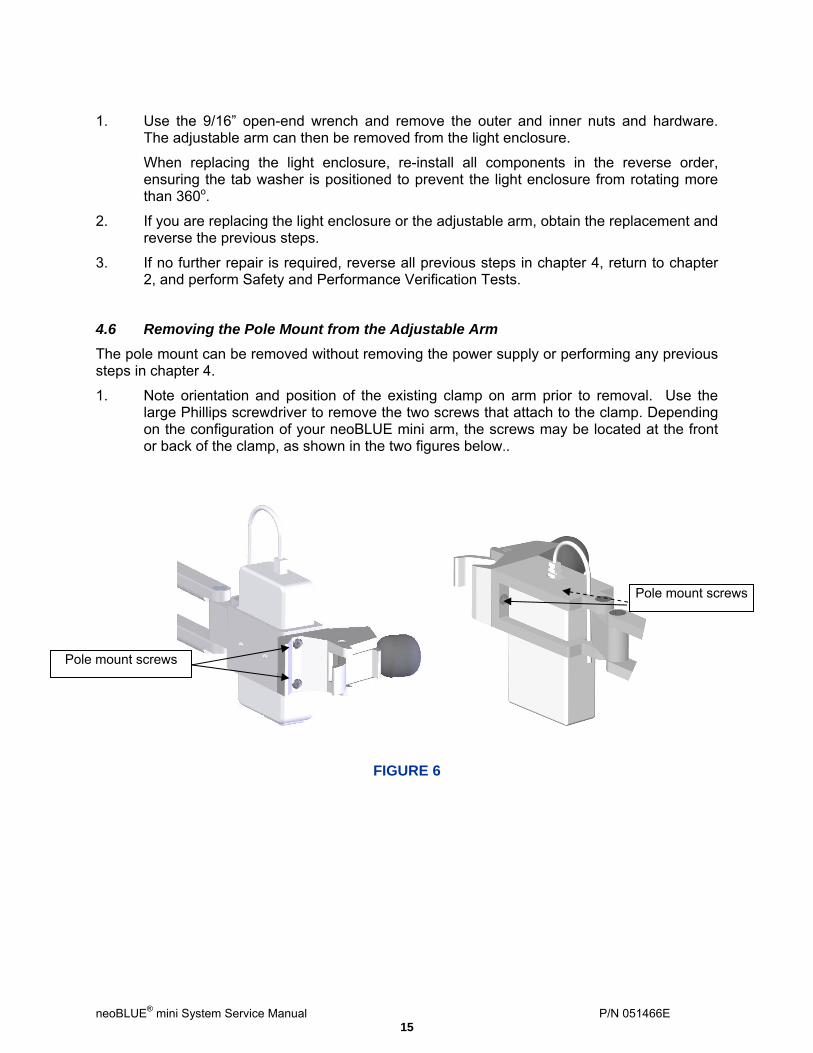
4.6 Removing the Pole Mount from the Adjustable Arm
The pole mount can be removed without removing the power supply or performing any previous steps in chapter 4.
1. Note orientation and position of the existing clamp on arm prior to removal. Use the large Phillips screwdriver to remove the two screws that attach to the clamp. Depending on the configuration of your neoBLUE mini arm, the screws may be located at the front or back of the clamp, as shown in the two figures below..
Pole mount screws
Pole mount screws
FIGURE 6
neoBLUE® mini System Service Manual P/N 051466E 15

Spare Parts List
Note: Only the gooseneck portion of the adjustable arm is shown above.
Item No.
Part Number
Description Qty.
1 040806 Adjustable Arm with Pole Mount and Power Supply
1
2 040821 Enclosure, Polycarbonate
1
3 040783 Current PCB 1
4 040915 LED PCB 1
5 800240 Nylon Washer 2
6 600122 On/Standby Switch 1
7 030745 Plate w/Insert 1
8 030748 Tab Washer 1
9 800244 Locking Nut 1
10 800106 Screw, Phillips Pan Head, 4-40 x ¼”, SS
8
11 030741 Lens, Polycarbonate
1
12 900680
Spare Pole Mount (Not Shown)
1
neoBLUE® mini System Service Manual P/N 051466E 16

neoBLUE® mini System Service Manual P/N 051466E 17
C H A P T E R 5
MEASURING THE NEOBLUE MINI LIGHT WITH A RADIOMETER This section provides important information about using radiometers to measure the light intensity output of the neoBLUE®mini LED Phototherapy device. Natus recommends that the neoBLUE mini light intensity output be checked with a radiometer per hospital protocol or at least every six months. In addition, your radiometer should be calibrated according to the manufacturer’s specifications (typically on an annual basis). Checking intensity before each use will confirm the “dosage” of light being delivered. In addition, by checking the intensity at the center of the infant and at the infant’s head and feet, you can confirm proper placement of the light. The intensity of the light is inversely related to the distance from the source. The neoBLUE mini LED Phototherapy system can be placed closer to the infant, yielding a higher intensity and thus delivering a higher dosage treatment. Please refer to Section 2.3.2, Adjusting Light Intensity, to adjust the neoBLUE mini light to the desired intensity when changing the distance. Natus recommends calibrating to between 30 – 35 μW/cm2/nm. The light intensity output of the neoBLUE mini device is measured with the neoBLUE® Radiometer by the manufacturer prior to shipment. Because your facility may use a different radiometer to measure light intensity output, it is necessary to understand how your reading correlates to the Natus reading. The following table provides a light intensity output conversion chart, when measured at 12 inches (30.5 cm) from the center of the neoBLUE mini light enclosure. NEOBLUE LIGHT INTENSITY OUTPUT CONVERSTION CHART
Radiometer:
Natus® neoBLUE® Radiometer *
Ohmeda Bili- blanket® Meter II
Joey® Dosimeter Model JD100
Olympic® Bili- meter®
35 35 91 23 Intensity: (µW/cm2/nm) 30 30 78 20
* This Radiometer (P/N 53870) is used for measuring the neoBLUE light intensity output prior to shipment. If you have any questions, please contact Natus Medical Incorporated Technical Service at 1-800-303-0306 or your authorized service representative.