servicing111110constructioncolourdevropments … · servicing111110constructioncolourdevropments tv...
TRANSCRIPT
SERVICING111110CONSTRUCTIONCOLOURDEVROPMENTS
TV I AY 1976
C C D
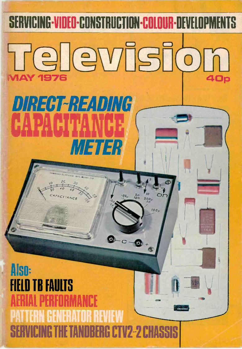
vuDIRECT -READING
CAPACITANCEMETER
Also:
FIELD TB FAULTS
Pill
0 ITU
=ICING TN TANDBERG Cl.I C Abbli
"I MADE IT MYSELF"Imagine the thrill you'll feel ! Imagine how impressedpeople will be when they're hearing a programme on amodern radio you made yourself.
Now! Learn the secrets of radioand electronics by building your
own modern transistor radio!Practical lessons teach you sooner
than you would dream possible.
What a wonderful way to learn - and pave the way to anew, better -paid career! No dreary ploughing through pageafter page of dull facts and figures. With this fascinatingTechnatron Course, you learn by building!
You build a modern TransistorRadio . . . a Burglar Alarm. You learnRadio and Electronics by doing actualprojects you enjoy - making thingswith your own hands that you'll beproud to own! No wonder it s so fastand easy to learn this way. Becauselearning becomes a hobby! And what aprofitable hobby. Because oppor-tunities in the field of Radio andElectronics are growing faster thanthey can find people to fill the jobs!
No soldering - yet youlearn faster than youever dreamed possible.Yes! Faster than you can imagine, youpick up the technical know how youneed. Specially prepared step-by-steplessons show you how to: read circuits-assemble components- build things -experiment. You enjoy every minuteof it!
You get everything you need. Tools.Components. Even a versatile Multi -meter that we teach you how to use.All included in the course AT NOEXTRA CHARGE! And this is a
course anyone can afford.
So fast, so easy,this personalised coursewill teach you even ifyou don't know a thingtoday!No matter how little you know now.no matter what your background oreducation, we'll teach you. Step bystep, in simple easy -to -understandlanguage, you pick up the secrets ofradio and electronics.
You become somebody who makesthings, not just another of the millionswho don't understand. And you couldpave the way to a great new career,to add to the thrill and pride youreceive when you look at what youhave achieved. Within weeks youcould hold in your hand your owntransistor radio. And after the courseyou can go on to acquire high-powered technical qualifications.because our famous courses go rightup to City & Guilds levels.
Send now for FREE44 page book - see howeasy it is - read whatothers say!Find out more now! This is the gate-way to a thrilling new career, or awonderful hobby you'll enjoy foryears. Send the coupon now. There'sno obligation.
POST
TODAY FOR
FREE BOOK
DEPT CTV17, READING RG7 4PFAl so at our London Advisory Office. 4 Fore Street Avenue,Moorgate, London EC2Y 5EJ. Tel,. 01-628 2721Yes, I'd like to know more about your course. Please sendme free details - plus your big, 44 -page book that tellsabout all your courses.
To: ALDERMASTON COLLEGE CTV11
NAME
ADDRESS
POST CODE LB I Er
HOME OF BRITISH INSTITUTE OF ENGINEERING TECHNOLOGY
COLOUR, UHF & TELEVISION SPARESCROSS HATCH UNIT KIT, NEW AERIAL INPUT TYPE, INCLUDEST.V. SYNC AND UHF MODULATOR. BATTERY OPERATED. CANBE USED FOR ANY SET £11.00 + 45p p.p. COMPLETE TESTEDUNITS, READY FOR USE (ALUMN CASE) f 16.60, (DE -LUXE CASE)£18.00 p.p. 75p.NEW GREY SCALE KIT, ADDS ON TO ABOVE CROSS HATCHKITS AND UNITS £2.90 p.p. 25p."NEW TYPE SIGNAL STRENGTH METER, ONE CONTROL,P.C. BOARD FULL KIT £18.00 p.p. 65p. "TELEVISION"SIGNAL STRENGTH METER KIT £16.30 p.p. 65p. G8 SURPLUSVIS. SELECT. PANEL 25p. VIS. GAIN PANEL 25p p.p. 25p.CRT REACTIVATOR PROJECT FULL KIT £17.48 p.p. 80p."TELEVISION" CONSTRUCTOR'S COLOUR SET PROJECT.NEW MARK II DEMONSTRATION MODEL WITH LATESTIMPROVEMENTS. TWO SETS WORKING AND ON VIEW AT172 WEST END LANE, N.W.6. TREMENDOUS RELIABILITYSUCCESS OVER 2 YEARS. CALL, PHONE OR WRITE FORUP-TO-DATE COLOUR LISTS."TELEVISION" PROJECT CROSS HATCH KIT £3.60 p.p. 20p.*VIDEO PRE -AMP MOD. KIT (Oct. '75 Article) £1.20 p.p. 20p.SPECIAL OFFER I.F. Panel, leading British maker, similar design to"Television" panel. Now in use as alternative incl. circuit, and connectiondata, checked and tested on colour £12.80 p.p. 70p. Also DECODERpanel checked and tested on colour, full details, f16.80 p.p. 70p."FIVE in ONE" PANEL replaces Tuner IF, Decoder, RGB, and soundboards of original project. Tested on colour, with all data. £26.00 p.p. 80p.MAINS TRANSFORMER 280W for "T.V." Colour Set £11.50 p.p. £1.20.P.C. BOARDS. Convergence 3 for £2.75 p.p. 55p. Time Base £1.25,Power £1.50 p.p. 50p. R.G.B. Varicap, C.R.T. Base 75p p.p. 30p.PACKS (IncL p.p.). No. 2 £4.62, No. 5 £1.25, No. 9 49p, No. 12 37p,No. 13 49p, No. 14 £11.50, No. 15 £2.48, No. 16 f10.55, No. 17 £3.25,No. 18 (Components) £8.70, No. 19 £2.70, No. 21 £9.95, No. 22 £2.20,C.R.T. Shields £2.30 p.p. 90p, Pack No. 23 £3.05. Pack No. 24 £1.40.TAA 350 DAM p.p. 15p. New Audio Unit £2.60 p.p. 30p.STABILISER UNITS, "add on" kit for either 40V or 20V, £2.80 p.p. 35p.Field & Line Blanking Mod. Kit 30p, Beam Limiter Mod. Kit £1.00.Line Osc. Coil 60p. 500 ohm Contrast 25p, 250 ohm 25W 32p, AI SlideSwitches (Break before make) 3 for 48p. Ident Coil 50p. p.p. 12p.G.E.C. 2040 decoder panels for parts, DL20, Xtal, ident, etc., £3.50
P-P70PPYE 697 Line T.B. for "Television" set parts £1.50 p.p. 60p.MULLARD AT1023/05 convergence yoke. New £2.50 p.p. 60p.MULLARD DLIE delay line. New £1.25 p.p. 30p.PHILIPS G6 single standard convergence panel, incl. 16 controls, switcheswtc., and circuits £3.75 p.p. 60p, or incl. yoke £5.00 PHILIPS G8 panelsfor spares, decoder £2.50 p.p. 65p. Field/line osc. 75p p.p. 35p.VARICAP, Mullard ELC1043 UHF tuner £4.20, ELC1043/05 £5.00,G.I. type UHF varicap tuner £2.50 p.p. 30p. VHF or UHF salvagedvaricap tuners f1.40. Control units, 3PSN £1.25, 4PSN £1.80, 5PSN £2.30.Special offer 6PSN £1.00, 7PSN £1.80 p.p. 25p. TAA 550 50p p.p. 15p.ELC1042 VHF varicap tuner on maker's p.c.b. £6.00, 'plug in' 6 positioncontrol unit £2.50 p.p. 65p.UHF/625 Tuners, many different types in stock. Lists available. UHFtuners transistd. £2.85, incl. s/m drive, indicator £3.85; 6 position, or4 position pushbutton £4.20 p.p. 60p. Integrated tuners BUSH, DECCA6 postn pushbutton or PHILIPS Rotary £4.50 p.p.70p.AE ISOL 30p p.p.20p.TRANSISTORISED 625 IF for TN., sound. tested (as featured inPractical Wireless, Nov. '75). £6.80 p.p. 65p.PHILIPS 625 I.F. Panel incl. cct 50p p.p. 50p.FIREBALL TUNERS Ferg., HMV, Marconi, New £1.00 p.p. 55p.TURRET TUNERS, KB "Featherlight" VC11. Philips 170 series. GEC2010 £2.50. PYE-PAM, Invicta, Miniature, increm. £1.00 p.p. 50p.TBA "Q" I.C.s. 520, 530, 540, £2.20, 550, 560C, 920, 990 13.20 p.p. 15p.LINE OUTPUT TRANSFORMERS. New guar. p.p. 65p.
BUSH 105 to 186SS, etc £6.40 SPECIAL OFFERS
DECCA DR95, 101/606, DRI BUSH TV53/86 f 1.00
2, 3, 121/123, 20/24, 2000 £5.90 BUSH TV95/99 £2.50EKCO 380 to 390 £1.00
FERG., HMV, MARCONI, EKCO 407/417 £1.00PHILCO, ULTRA, THORN FERR. 1057 to 1068 f1.00
850, 900, 950, 1400, 1500 series . £5.80 FERR. 1084/1092 f1.00
GEC 302 to 456, 2000 series £5.90 FERG. 506 to 546HMV 1890 to 1896
f 1.00f1.00
KB VC I/9 51, 52, 53, 100, 200 ... £5.80 KB/RGD 003, VC 11 £2.75MURPHY 849 to 2417, etc. £6.40 P/SCOTT 1419 toP/SCOTT 960, COSSOR 1964 ... £4.90 1725, 733 to 738 £1.00
PHILIPS 19TG121 to 19TG156 £5.90REG 10-6, 10-17REG 191/2, 17-18
£1.00£1.00
PHILIPS 19TG170, 210, 300 £5.90 RGD 519 to 620 £1.00PYE I I U, 20, 30, 40, 67, 169,
368, 569, 769 series £5.90
PHILCO 1010/21SOBELL 195/282/8
f 1.00£2.50
PAM, INVICTA, EKCO, COLOUR LOPTS p.p 75p
FERRANTI equivalentsSOBELL 1000 series
£5.80 BUSH CTV 182 Ser.GEC 2028, 2040PYE 697
£6.60£9.20
f11.50STELLA 1043/2149 £5.90 MULLARD AT2055 £5.80THORN 850 Time Base Panel, Dual Standard 50p p.p. 60p.MULLARD Scan Coils Type ATI030 for all standard mono 110°models, Philips, Stella, Pye, Ekco, Ferranti, Invicta £2.00 p.p. 65p.PHILIPS G8 Tripler (1174) £5.00. GEC 2040 series £1.75 p.p. 55p.
CALLERS WELCOME AT SHOP PREMISES
MANOR SUPPLIES172 WEST END LANE, LONDON, N.W.6.(Near W. Hampstead tube stir 28, 59, 159 Bus Routes) 01-794 8751
Mail Order: 64 GOLDERS MANOR DRIVE, LONDON, N.W.11.PLEASE ADD 25% VAT TO PRICES OF GOODS (EXCEPT 8%)
COPYRIGHTIPC Magazines Limited, 1976. Copyright in
all drawings, photographs and articlespublished in Television is fully protected andreproduction or imitation in whole or in partis expressly forbidden. All reasonableprecautions are taken by Television to ensurethat the advice and data given to readers arereliable. We cannot however guarantee it andwe cannot accept legal responsibility for it.Prices are those current as we go to press.
CORRESPONDENCEAll correspondence regarding advertisementsshould be addressed to the AdvertisementManager, "Television", Kings Reach Tower,Stamford Street, London SE1 9LS. All othercorrespondence should be addressed to theEditor, "Television", Fleetway House,Farringdon Street, London EC4A 4AD.
BINDERS AND INDEXESBinders (£2.10) and Indexes (45p) can besupplied by the Post Sales Department, IPCMagazines Ltd., Lavington House, 25Lavington Street, London SE1 OPF. Pricesinclude postage and VAT.
BACK NUMBERSWe regret that we are unable to supply backnumbers of Television. Readers arerecommended to enquire at a public library tosee copies. Requests for specific backnumbers of Television can be published inthe CQ Column of Practical Wireless bywriting to the Editor, "Practical Wireless",Fleetway House, Farringdon Street, LondonEC4A 4AD.
QUERIESWe regret that we cannot answer technicalqueries over the telephone nor supply servicesheets. We will endeavour to assist readerswho have queries relating to articlespublished in Television, but we cannot offeradvice on modifications to our publisheddesigns nor comment on alternative ways ofusing them. All correspondents expecting areply should enclose a stamped addressedenvelope.Requests for advice in dealing with servicingproblems should be directed to our QueriesService. For details see our regular feature"Your Problems Solved".
TelevisionSERVICINGVIDEOCONSTRUCTIONCOLOURDEVELOPMENTS
this month341 Examinations
Comment.
342 TeletopicsNews and developments.
VOL. 26NO.7
ISSUE 307MAY1976
344 Small Picture and Other Field FaultsSurvey of valve field timebase faults and their causes.
349 Direct -Reading Capacitance MeterA simple battery -powered instrument based on theNE555 timer i.c.
353 Next Month in Television
354 Field Timebase Circuit for the PIL TubeDescription of the circuit used by Korting to drive thefield windings of the PIL tube's toroidal yoke.
356 U.H.F. Aerial PerformanceInvestigation of the performance characteristics of agroup of well-known commercial arrays.
358 Video Effects Generator, Part 2Constructional details plus instructions for use.
363 Servicing Television ReceiversGEC Portable Model 2114 - Junior Fineline(continued)
367 Miller's MiscellanyA light-hearted look at some servicing problems.
370 Long -Distance TelevisionReports of DX reception and news from abroad.
374 Servicing the Tandberg CTV2-2 ChassisNotes on common faults experienced withthis 110° chassis.
377 TV Test Patterns and Signals, Part 2Features and uses of the Vertical IntervalTest Signals.
381 Which Pattern?The fourth part of our TV Test Equipment Reviewseries looks at pattern generators.
386 Your Problems SolvedA selection from our Readers' Query Service.
387 Test Case, No. 161Can you solve this servicing problem? Plus lastmonth's solution.
by John Law
by A. Wilcox
by S. George
by Roger Bunneyand Ian Beckett
by E. A. ParrB.Sc. C.Eng. MIEE
by L. Lawry -Johns
by Chas. E. Miller
by Roger Bunney
by W. S. J. BriceB.Sc.(Eng.)
by Harold Peters
OUR NEXT ISSUE DATED JUNE 1976 WILLBE PUBLISHED ON MAY 17
by E. Trundle
TELEVISION MAY 1976 337

CHINIAGLIA
For details of this and the many other excitinginstruments in the Chinaglia range, including multi -meters, component measuring, automotive andelectronic instruments please write or telephone:
INTRODUCING THE
DOLOMITI20k0/V a.c. and d.c.A NEW HIGH SENSITIVITY MULTIMETERWITH ALL THE FEATURES YOU WILL EVER NEEDAccuracy: D.C. ranges, + 2.0%, A.C. & O ranges ± 2-5%.39 ranges: d.c.V, 0-150mV, 500mV, 1-5V, 5V, 15V, 50V, 150V, 500V,
1 5kV; d.c.1, 0-50pA, 500pA, 5mA, 50mA, 0 5A, 5A;a.c.V, 5V, 15V, 50V, 150V, 500V, 1 -5kV; a.c.l, 5mA, 50mA,0-5A, 5A: dB -10 to +65 in 6 ranges; 0 0-0-5k0, 5k0,50k0, 500k0, 5M0, 50M0; pF 50kpF, 500kpF.
Automatic overload protection and high current range fusing.Scale mirror and fine pointer for accuracy of reading. Single knob mainrange switching and all panel controls. C.E.I. Class 1 movement withsprung jewel bearings. Extended 92mm scale length for extra clarity.Compact ABS case 125 x 131 x 37mm. Weight 650g with batteries.Supplied complete with carrying case, fused leads, handbook and full12 -month guarantee. Optional 30kV d.c. probe available.
Meter £33.15 incl. VAT (80p. P. & P.)30kV Probe £10.80 incl. VAT
at OM Instruments Ltd.19 MULBERRY WALK LONDON SW3 6DZ TEL: 01-352 1897
TRAIN for SUCCESSStart training today and make sure you arequalified to take advantage of the many oppor-tunities open to the trained person. ICS canfurther your technical knowledge and providethe specialist training so essential to success.
ICS, the world's most experienced home studycollege, has helped thousands of ambitious mento move up into higher paid jobs - they can dothe same for you.
Fill in the coupon below and find out how!There is a wide range of courses to choose
from, including:CITY & GUILDS CERTIFICATESTelecommunications Technicians'Radio TV Electronics Technicians'Electrical Installations Technicians'Electrical Installation WorkRadio Amateurs'
MPT Radio Communications Cert.EXAMINATION STUDENTS -GUARANTEED COACHINGUNTIL SUCCESSFUL
TECHNICAL TRAININGICS offer a wide choice of non -examcourses designed to equip you for a betterjob in your particular branch ofelectronics, including:Electronic Engineering & MaintenanceComputer Engineering/ProgrammingRadio, TV & Audio Engineering &
ServicingElectrical Engineering. Installations &
Contracting
COLOUR TV SERVICINGTechnicians trained in TV Servicing are in constant demand. Learn allthe techniques you need to service Colour and Mono TV sets throughnew home study course approved by leading manufacturer.
POST THIS COUPON OR TELEPHONE FOR FREE PROSPECTUS
I am interested in
Name Age
Address
Occupation
Accreditedby CACC
Member of ABCC
To:International Correspondence Schools,'Dept BOOS, Intertext House, LONDONSW8 4UJ or phone 01-622 9911 (all hours) II
MMMMMMMM MI MIN IN
REBUILT COLOUR TUBESALL SIZES AVAILABLE
Full range of rebuilt mono tubes available,Standard, Rimband and Twin Panel.
* Complete new gun fitted to every tube.* 12 months' guarantee.* 18 years' experience in tube rebuilding.* Trade enquiries welcomed.
N.G.T. ELECTRONICS LTD.20, Southbridge Road, Croydon, Surrey
Telephone: 01-681 7848/9
VALVE BARGAINS
Any 5 64p, 10 £1.10, 50 £5. Yourchoice from the following list:
ECH84, ECC82, EF80, EF183,E F184, PC86, PC88, PCF80,PCF802, PCL82, PCL84, PCL85,PCL805, PFL200, PL36, PL504,PY81, PY800, PY88, EH90,30PL1 4, 6F28
Colour Valves 30p each PL508,PL509, PY500/A.
AERIAL BOOSTERSWe make three types of AerialBoosters all for set top fitting, withCo -ax Plugs and Sockets.B11 -For Stereo and Standard
VHF Radio.B12 -For the older VHF Tele-
vision, please state BBC1 andITV Channels.
B45 -For mon. or colour thiscovers the complete UHFband.
All Boosters are complete withbattery and take only minutes tofit.
Price £3.90 each.Small Plastic Boxes (white) made out of high impact plastic with flick on lids.Ideal for most projects. All three tpes one price. Prices 15p each. Ten £1 .30.Size (approx.): Type 1-34ins 2*ins x lin deep. Type 2-3}ins x 21ins x tinsdeep. Type 3-31ins x 34 -ins x llins deep.
Prices include V.A.T. P. & P. under £1: 15p, £ 1 to £3: 20p. above f3: 30p.Overseas at cost. Money back guarantee on all orders.
ELECTRONIC MAILORDER LTD.,62 BRIDGE ST., RAMSBOTTOM, BURY, LANCS. Tel. Rams. 3036
338 TELEVISION MAY 1976
B. BAMBER ELECTRONICS Dept. T, 5 STATION ROAD, LMLEPORT, CAMBS. CB6 1QETel: ELY (0353) 860185 (2 lines) Tuesday to Saturday
WELLER SOLDERING IRONS(TRADE ENQUIRIES WELCOME)EXPERTBuilt -in -spotlight illuMinates work.Pistol grip with fingertip trigger.High efficiency copper soldering tip.EXPERT SOLDER GUN£6.80 + VAT (54p)EXPERT SOLDER GUN KIT(SPARE BITS, CASE, ETC.)f9.80 + VAT (78p)SPARE BITSPAIR, 26p + VAT (2p)MARKSMAN SOLDERING IRONUnbreakable heat -resistant handle.Stainless steel barrel.Special steel heating elements with Micainsulation bedded in ceramic.SP15D 15W £2.52 + VAT (20p)SP25D 25W £2.52 + VAT (20p)SP25D 25W + BITS etc, KIT £3.12 +VAT (25p)BENCH STAND with spring for MARKS-MAN IRONS E1.80 + VAT (14p)Spare sponges, as for TCP1.SPARE BITSMT8 for 15W 42p + VAT 13p)MT4 for 25W 35p + VAT (3p)TCP1 TEMPERATURE CONTROLLEDIRON
TCP1 + PU1DTemperature controlled iron and PSU.£18.43 + VAT 1f1.47)SPARE TIPSType CC SINGLE FLAT, Type K DOUBLEFLAT, FINE TIP90p each + VAT (80HEATING ELEMENTHE -60 £3.00 VAT (24p)SPONGESP -60 20p + VAT (2p)BARREL ASSEMBLYBA -60 88p + VAT (7p)W060 TEMPERATURE CONTROLLEDIRON(As TCP1 but Mains Operated 240V AC)£10.54 + VAT (84p)OTHER WELLER PRODUCTS & SPARESAVAILABLE EX -STOCK
SERVISOL PRODUCTSSuper ServisolSilicone GreaseFoam CleanserPlastic SealAero KleneAnti -Static Spray MistSolda-MopServisol standard tinSupa Freeze -It Boz tin
65p + VAT (5p)60p + VAT (5p)60p + VAT (5p)55p + VAT (4p)50p + VAT 14p150p + VAT (4p)60p + VAT (5p)65p Zero VAT65p + VAT (5p)
DISCOUNT -10 OFF -10%(MIXTURE OR 10 OF ONE PRODUCT)
MULTICORE SOLDERSize 5 SAVBIT 18swg in alloy dispenser32p + VAT )3p)Size CI SAV18 SAVBIT 18swg56p + VAT (4p)Size 12 SAVBIT I 8swg on plastic reel£1.80 + VATI15p)
MINIATURE PLIERSHIGH QUALITY"CRESCENT"MADE IN USA£4.35 + VAT (35p)
SIDE CUTTERSHIGH QUALITY"CRESCENT"MADE IN USAf5.45 + VAT (44p)
SOLDER SUCKERS(HIGH QUALITY, PLUNGER TYPE)STANDARD £4.50 + VAT 136p)WITH SKIRT £4.95 + VAT (40p)Spare nozzles (PTFE) 60p + VAT (5p)
RUBBER BULB TYPEA handy inexpensive tool for the quickremoval of solder. Small, lightweight andeasy to use. Teflon tiplets easily changed orreplaced.No. 881 Complete Tool E1.20 + VAT (10p)No. 8810 Nozzle only 50p + VAT 14p)
HIGH QUALITY SPEAKERS, 84" x 6"elliptical, only 2" deep, inverse magnet,4 ohms, rated up to 10W, £1.50 each +VAT (38p) or 2 for £2.75 + VAT Mel(quantity discount available).
SPIRALUX. AUTO SETS AND NUTSPINNER SETSAuto Sets and Nut Spinner sets areattractively packaged in a plastic wallet.Each set has cellulose acetate handle.Model 2210 Nut Spinners BA.Contents 0, 1,2, 3, 4, 5, 6, 8. £4.00Model 2230 Nut Spinners metric.Contents 4, 4.5, 5, 5.5, 6, 7, 8, 9, 10. E4.34Model 2240 Nut Spinners BA.Contents 0, 2, 4, 6, 8. £2.86PLEASE ADD 8%VAT.
SPIRALUX NUT SPINNERSThe following nut spinners are fitted withcellulose acetate handles and have chromiumplated shafts.Shank length 6"-150mmModel Size Price4500 OBA 74p4502 28A 74p4504 4BAf"-AF 74p4506 6BA 86p4508 SBA 66p4540 4mm 66p4545 4.5mm 66p4550 5mm 88p4555 5.5mm 86p4560 6mm 74p4570 7mm 74p4580 8mm 74p4590 9mm 74p4510 lOmm 74pPLEASE ADD 8% VAT.
SPIRALUX SCREWDRIVERSFitted with cellulose acetate handles. Theblades are chromium plated and conformwith 8.S.2559 where applicable.E LECTRICIANS INSULATEDModel Blade size Price3222 (364E) 4"-100mm 47p3223 (366E) 6"-150mm 47p3224 (368E1 8"-200mm 50p3225(3610E1 10"-250mm 50p
E NGINEERS3332 (464) 4" x 1" -100 x 6mm3333 1466) 6" x I" -150 x 6mm3343 (566) 6" x 4"-150 x 8mm3344 (568) 8" x h"-200 x 8mm
Model Blade size Price
3354 (6681 8" x 4" -200 x 9.5mm 84p3355 166101 10" x 4" -250 x 9.5mm 86pPOZIDRIVModel Blade size Price3521 (Poe 1) 3"- 75mm x No 1 Point 66p3532 (Poz 2) 4"-100mm x No 2 Point 70p3543 (Poz 3) 6"-150mm x No 3 Point f 1.023554 (Poz 4) 8"-200mm x No 4 Point £1.18PLEASE ADD 8% VAT.
DIECAST BOXESThe range of aluminium alloy diecast boxeshas the unique feature of internal slots fordividing parts, e.g. screens, printed circuitsboards etc. For use as screened sub-assemblies, as rigid chassis, as junctionboxes, for test sets and for completeequipment.In the following sizes:4.3" x 2.3" x 1.2" approx.4.8" x 2.3" x 1.5" approx.4.8" x 3.8" x 1" approx.4.8" x 3.8" x 2" approx.6.8" x 4.8" x 2" approx.4.8" x 3.8" x 3" approx.6.8" x 4.8" 04" approx.8.6" x 5.8" x 2" approx.
10.6" x 6.8" x 2" approx.PLEASE ADD 8% VAT.BARGAIN PACKSMIXED DIELECTRIC CAPACITORS(Approx. 100) £1.50ELECTROLYTICS (LOW VOLTAGE TYPES)(Approx. 1001 £1.50ELECTROLYTICS (HIGH VOLTAGE TYPES)(Approx. 35/ £1.50RESISTORS (MIXED WATTAGES) MIXEDVALUES, large pack £1.00PLEASE ADD 25% VAT.
PLUGS & SOCKETST.V. PLUGS (Metal Type)T.V. SOCKETS (Metal Type)T.V. LINE CONNECTORS(Back-to-back sockets)
47p DIN 3 -pin LINE SOCKETS50p DIN 3 -pin PLUGS68p DIN 6 -pin Right-angled PLUGS70p PLEASE ADD 25% VAT.
(not slotted) 85p75p85p
£1.00E1.45E1.55f2.25£1.85£2.25
5 for 50p4 for 50p
4 for 50p15p each15p each20p each
Terms of Business: CASH WITH ORDER. MINIMUM ORDER £1.00. ALL PRICES INCLUDE POST & PACKING (UK ONLY). SAE withALL ENQUIRIES Please. PLEASE ADD VAT AS SHOWN. ALL GOODS IN STOCK DESPATCHED BY RETURN. QUANTITY TRADEDISCOUNT AVAILABLE ON MOST ITEMS.
LINE IT UP WITH A BI-PRE-PAK MARK 2
iiPREALIC LTD.
battery
off
videoon output.!%
synth.
Cross hatch grittpter\,,k of- _* 4 -PATTERN SELECTOR SWITCH* SIZE 3" x 5+" x 3" (76 x 133 x 76mm)* OPERATES FROM 3 SELF-CONTAINED
U.2 TYPE BATTERIES* FUNCTIONS TO PROFESSIONAL STANDARDS
TV SIGNALSTRENGTHMETER
As described in this journal. A finelydesigned instrument of enormous value to theTV engineer, etc. Complete kit of guaranteed
parts, and as specified £19.50 + 50ppostage & packing + V.A.T. at 8%.
These TV instruments are two examples of the manyattractive items sold by Bi-Pre-Pak. For catalogue of theseand audio modules, semi -conductor bargains, books, etc.,send large S.A.E. envelope with 10p stamp.
BI-PRE-PAK LTD(Reg. No. 820919)
Dept. X, 222-224 WEST ROADWESTCLIFF-ON-SEA, ESSEX SSO 9DFTelephone Southend (0702) 46344
CROSS HATCHGENERATORIN KIT FORM OR READY -BUILT
Based on the design originally published in "TELEVISION" thisunit is invaluable to industrial and home users alike. Improvedcircuitry assures reliability and still better accuracy. Generates fourdifferent line patterns to facilitate lining -up, etc., at the turn of thepattern selector switch. Very compact; self-contained. Robustly built.Widely used by TV rental and other engineers. In strong re-
inforced fibre -glass case, instructions, but less batteries. INDIS-PENSABLE FOR COLOUR.
In Kit form £7.93
Ready built and tested £9.93add 8% for V.A.T. to total value of order plus 50p for postage andpacking (in U.K.)
gimEN mi mmm mi =I
81-PRE-PAK LTD. 222 West Rd., Westcliff, Essex SSO 9DF
Please send X -Hatch Generator Kit D BuiltOTV Signal Strength Meterfor which I enclose f inc. V.A.T. & post & packing.
NAME
ADDRESS
MI NMI IIMI MNI= INN
TELEVISION MAY 1976 339
ADVERTISEMENT
Service Pack of Electrolytics FANTASTIC OFFER 86 FOR £2.50 PER PACK
.47/50v 2.2/50v 3.3/50v 4.7/16v 4.7/35v 10/10v 10/16v 10/35v 10/50v 22/6.3v 22/10v 22/16v 22/25v33/16v 33/25v 33/50v 47/16v 47/10v 47/16v 47/25v 47/50v 100/6.3v 100/10v 100/16v 100/25v 100/35v100/50v 220/6.3v 220/25v 220/35v 220/50v 330/16v 330/35v 470/10v 470/16v 470/25v 470/35v1000/10v 1000/16v 1000/25v 1000/35v 1000/50v 2200/6.3v 3300/6.3v 4700/6.3v 1000/35v 2200/6.3v220/10v 220/16v 220/25v 220/35v 220/50v 330/6.3v 470/6.3v 470/10v 470/25v 470/35v 470/50v 33/6.3v33/16v 33/35v 33/50v 47/6.3v 47/10v 47/16v 47/25v 47/35v 47/50v 100/6.3v 100/16v 100/25v 100/35v100/50v 150/10v 1/50v 3.3/50v 4.7/50v 10/25v 10/35v 10/50v 22/16v 22/25v 22/35v 22/50v 10/25v220/10v
100 Green Polyester Condensers. Mixed Values. £2.00 per 100.
UHF VARICAP TUNER UNIT, £2.50 NEW
18Kv Diode 2 M/ABYF3123 40p
New Luminance DelayCoil 80p
1 Amp. 100 P.I.V. Bridge rectifier 20p
P.N.P.N. SILICON REVERSE BLOCKINGTRIODE THYRISTORS 5A D.C. 30V to 300V30A SURGE CURRENT. 27p EACH
BD116 30p2N3055 EACH2N930 4p
Spark Cap 5p
UHF AE IsolatingSocket 35p TIC 106C
AA116 25 forAA117 £1.00 TBA510 f 1 .00
TBA480Q £1.00TBA550Q £1.50TBA720A £1.50TBA790B/31 £1.00TBA920 £2.00TBA970 £2.00TBA800 £1.00TAA700 £2.00TBA530Q £1.00TBA550 £2.00SN76544W 50pSN76640NQ £1.00SAA570 50pTBA120A 5op
4 Push Button Assemblyfor Varicap Unit £1.007 Push Button Assemblyfor Varicap Tuner £1.50
BF127BF180 15pBF181 EACHBF182
TRIPLERS25kV 2.5MA Silicone £1.5025Kv Selenium f1.30Decca 1730 £1.00GEC T25 KCI £3.50T5 11 TAZ £3.50
BU204 £1.00BU205 EACH
50 Mixed Diodes 50p
ThyristorsRZ427 300V 5A 27p
Scan Coil with Yoke £3.00
G8 Varicap V/Resistor Panel £1.20ThyristorsRCA 40506 50p 1000 + 2000 MFD 35V 20p
100 + 200 325V 30p2b0 + 200 + 100 325V 40p200 + 100 + 50 + 100 325V 40p200 + 200 + 100 + 32 350V 70p300 + 300 + 100 + 150 350V 70p400 + 400 200V 40p
R1039R2009 75pR2029 EACHR2030
MAINS DROPPERS147R -260R 25W 20p
.24c2 10% W/W Resistor10W 10PBDY55 4 FOR
2N3055 £1.00AE
VHF ISOLATINGUHF SOCKET
100 W/W Resistors £1.00300 Mixed Condensers f1.00300 Mixed Resistors £1.0040 Mixed Pots £1.0020 Slider Pots £1.0030 Mixed Preset Pots £1.00
50 Mixed Fuses SOp
EHT Rectifier SticksX80/150D 12pCSD118XPA 15p
MJE2021SJE5451 15p EACH90V 80W 5AColour TV
MComponentsanufacture,Manufacturers Dis-carded Materials
4,700M 25v 470M 25v2,000M 25v 470M 35v 121p1,000m 50v 470M 50v EACH1,000m 35v
BY127 10p
IN4007 20 for £1.00VHF or UHF VaricapTuners £1.20
170PF 8Kv 220M 35v180PF 8Kv 220M 40v1,000PF 8Kv 220M 50v1,000PF 10Kv 470M 40v lop
10Kv 22M 315v EACH160M 10M 250v220M 25v 100M 50v1000 MFD 16v
BZY 88CTV525 FOR £1.00
Line op Panels £1.20
G8 Type Yoke SOp ZW13 25 for £1.00
Mains power supply, made for 15 volt,Aerial Amps (inc. case) f1.00
VHF VARICAP NEW £2.50SENDZ COMPONENTS2 WOOD GRANGE CLOSE,THORPE BAY, ESSEX.Reg. Office only -No personal callers. Thank you.
UHF T/unit £1.50
BT116 75p
BY206 10p
PLEASE ADD 25% VAT
340 TELEVISION MAY 1976
EDITORLionel E. Howes
ASSISTANT EDITORJohn A. Reddihough
TECHNICAL EDITORGeoffrey C. Arnold
ART EDITORPeter Metalli
ADVERTS. MANAGERRoy Smith 01-261 6275
CLASSIFIED ADVERTS.Colin R. Brown 01-261 5762
530_ 172
co
EXAMINATIONSIt seems that whenever we raise the subject of training we get a tremendous post bag.There is no doubt about the lively interest in the matter amongst those involved intraining, those receiving the training, and those who subsequently employ the trained. Avariety of well -argued views have been put forward in a number of letters we havereceived recently. Probably the greatest divide is between those who feel that techniciansshould be given an all-round training so that they can understand and deal with mosttypes of electronic equipment, and those who feel that the most important point is thattechnicians should end up reasonably familiar with the equipment the trade is mainlyconcerned with - domestic radio and TV sets. With the limited amount of time available,it's not practicable to do both.
We respect the former view. An engineer with a detailed knowledge of the basicfundamentals of electronic circuit design obviously has the greater scope. Nevertheless weincline towards the latter view, that if we want capable TV technicians, say, then we've gotto ensure that their training makes them familiar with the techniques found in practice incommercial equipment and the types of fault that arise in day to day servicing - defectivesemiconductor junctions, burnt resistors, leaky capacitors and so on. Anyone aspiring towider knowledge can always take further courses after he's proved himself capable in aparticular field, and we don't think that's putting the cart before the horse.
Be that as it may however, this month we want to have a beef about those who set theexamination papers. A correspondent recently sent us a paper for part III (fourth year) ofthe City and Guilds 222 Mechanics' course. That's the final part, concerned exclusivelywith TV. Checking through the questions, we came to the conclusion we'd have donequite well. The circuitry chosen was mostly well known, and the questions asked about itwere straightforward. We first raised an eyebrow however when we came across a pieceof circuitry that we are certain doesn't in practice exist: a neat idea for providing colourc.r.t. protection against a horizontal white line in the event of field timebase failure. Itlooked to us as if it had been dreamt up by an examiner, and somehow lacked convictionas to its practicality. It was easy enough to see what it was supposed to do: but is it fair toask examinees about a circuit that's but a gleam in the examiner's eye? - they were alsoasked about what the effect of a fault in one of the components would be!
Not too serious that perhaps, but next we came across a question on the well knownthree PCL84 colour -difference output stage/clamp circuit used in so many hybrid colourreceivers. To test examinees' understanding of it, they were asked some questions aboutfaults. But let's first imagine that you weren't familiar with the particular circuit. One cluewould be the presence of a clamp pulse input. So it would not exactly help if, as here, thepulse input coupling capacitor was shown simply connected to the h.t. rail! (Because theoriginal manufacturer's circuit used the "harness line" technique in which you follow acommon line around the circuit, watching for where "b" goes in and comes out etc.) Themysterious fourth grid shown on one of the PCL84s can be forgiven perhaps.
But part of the question was what visible symptom would indicate whether a fault wasin the output stage or clamp part of the circuit. And to anyone familiar with the circuitthat's unanswerable. There are quite a number of faults that can and do occur.Presumably you were supposed to trot out a pat bit of theory along the lines that a clampfault would affect all the c.r.t. guns and thus the monochrome display, whilst an outputstage fault would affect only the colour reproduction. But you wouldn't have been right byany means. One of the most common clamp faults is change of value of the resistors ineach clamp triode anode circuit - anyone with a bit of practical knowhow would spotthose high -value resistors straight away. And this clamp fault alters the colours of course!Conversely, no clamp is perfect, and the clamp action occurs only during the line flyback.Output stage faults can still disturb the c.r.t. grid conditions, the "monochrome" displaythen taking on a colour cast.
It's difficult to set a fair and varied selection of questions that is going to provide areasonable assessment of a candidate's ability. But it's a damn sight more difficultattempting to answer an unanswerable question or to try to divine what an examinercould possibly be getting at. It's also a waste of everyone's time, since technicalcompetence is not being assessed.
Candidates may have to contend not only with incorrect information and dubiousquestions but also with confusing presentation. A few years ago we edited a book (not onTV this time) which had at the end a collection of examination papers on the course thebook covered. On going through them we decided to draw to the author's attention thefact that many of the questions were vague or didn't make much sense. Hisunderstandable comment was "all I can do is to prepare readers for the sort of questionsthey're likely to be asked!"
We're undoubtedly complaining about a small minority of examination questions. Butit does strike us as unforgiveable when the examiners make a botch of the examining.Meanwhile, candidates have been warned!
TELEVISION MAY 1976 341
RESULTS FOR 19751975 was noteworthy for the UK electronics industry as awhole, being the first year since 1971 that an overall tradesurplus was shown - exports were 35% up while importsrose only 7.5%, giving a small overall surplus of £4.21million. Imports of domestic electronics products - whichplayed such a large part in the deficits recorded during theprevious three years - fell by 7.6%, while exports rose by25%. There was still a substantial deficit in this sectorthough. Particularly heartening however was the result forthe colour TV set industry: imports fell by nearly 40% to£38.44 million while exports rose by more than 136% to£38.41 million, putting the industry almost intoimport/export equilibrium after the substantial deficits ofrecent years. We've always maintained that the UK TVsetmaking industry is competitive, and it does now seemthat if the necessary export sales effort is made it couldbecome a lasting positive contributor to the balance ofpayments.
Meanwhile, looking at the UK domestic market during1975, total colour set deliveries were down 28% comparedwith 1974, the final total being 1,590,000 sets of whichimports accounted for 264,000. There seemed to be signs ofa slight upturn in December. Total monochrome setdeliveries for the year rose by 15% to 938,000. The numberof imported sets here was much greater however - 433,000.
We commented recently (March) on the losses made bythe servicing side of the TV trade. A recent inter -firmcomparison report produced by the RTRA (which we mustnow learn to call the RETRA - Radio, Electrical and Tele-vision Retailers Association) shows that the average lossis even higher than we last reported - 27.8% in respect ofservice income and rental maintenance compared to costs,though before making allowance for stocks held and workcarried out under guarantee.
SET NEWS
In Teletopics last November we mentioned the luxurycolour TV set introduced by Grundig at the Berlin RadioShow. This has now been released on the UK market - at arecommended retail price of £629 including the "Telepilot12" 20 -function ultrasonic remote control unit. Anoteworthy technical point is that it is one of the first sets onthe UK market to use the Mullard 20AX in -line gun colourc.r.t. - type A66 -500X. Just to recap some of the features ofthis unique set: at the touch of a button on the remotecontrol unit the time is displayed superimposed on thepicture, a quartz controlled digital clock being built in; the
new channel number appears for approximately eightseconds in the lower right-hand corner of the screenwhenever the channel is changed; and to help with settingup, a full -screen tuning meter showing all channels from 21-68 can be displayed on the screen. Servicing is assisted byusing 17 plug-in modules and by provision of a socket intowhich the Grundig "diagnostic adaptor" can be plugged toenable many of the circuits to be checked in one operation.There is also a new Grundig 12in. monochrome portable,Model P1216, with a recommended price of £104.80including VAT.
An 18 in. colour receiver with 110° in -line gun c.r.t. hasbeen added to the Skantic range. This is Model 47512 whichhas a recommended price of £263.96 plus VAT and isanother set featuring a service adaptor socket for rapiddiagnosis of basic faults. The c.r.t. fitted is one of theToshiba RIS types.
An interesting optional extra has been introduced byNordmende for use with their top two luxury colour models(which sell at over £700). This is the ASC-infra system,which enables the TV sets' sound signal to be transmittedby modulating an infra -red source (luminescent diodes) andpicked up via an infra -red detector on lightweight, cordlessheadphones. The headphones have their own independentvolume control, which can still be used with the set's volumecontrol turned right down. The advantages of using infra-red transmission are that it saturates the room - i.e. thereare no directional problems - while it doesn't penetrate thewalls to cause interference outside. F.M. is used for theinfra -red transmissions. The system adds £72 to the price ofthese sets - which also feature the Mullard 20AX tube. It isunderstood that other W. German setmakers are planningto introduce this cordless remote TV sound system, whichwas originally devised by Siemens.
COLOUR TUBES
The aftermath of the closure of the Thorn/RCASkelmersdale colour c.r.t. plant continues to haunt theindustry. It has been reckoned that the import bill foressential colour tubes will be about £30 million a year, andobviously more once production by UK setmakersincreases again. Mullard, the remaining UK colour tubemanufacturer, is now talking about making furtherinvestments though still loosing money on tubes. Obviouslygetting the 20AX tube into full production is going to callfor considerable expenditure.
But here's an interesting item of news that seems to showit's possible for governments to work together with theindustry. It is reported that the Finnish government is to
342 TELEVISION MAY 1976
take a 6096 stake in a new TV tube manufacturing plant,with leading Finnish setmaker Salora taking a 20% stakeand the remaining 20% stake being taken by Hitachi whowill provide the technical know-how. The initial productiontarget is 300,000 colour tubes a year, of which most will betaken by Salora while Hitachi will market the rest in W.Europe. If the Finns can be happily organising theestablishment of a colour tube industry one wonders whythe UK industry seems to get the worst of both worlds -capacity when its not needed and lack of capacity when itis.
TELETEXT DECODER SERVES 15,000Teletext as a free extra is being provided by Rediffusion totheir 15,000 cable subscribers in Brighton and Hove. Acable TV network is certainly the simplest way to makeCeefax/Oracle available - in this example a single decoderinstalled at the main aerial site serves the 15,000 receivinginstallations.
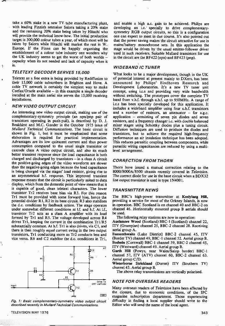
NEW VIDEO OUTPUT CIRCUITAn interesting new video output circuit, making use of thecomplementary -symmetry principle (an npn/pnp pair oftransistors operating in push-pull), is described by D. J.Beakhirst and M.C. Gander in the October 1975 issue ofMullard Technical Communications. The basic circuit isshown in Fig. 1, but it must be emphasised that someelaboration is required for practical implementation.Advantages are its low quiescent current and thus powerconsumption compared to the usual single transistor orcascode class A video output circuit, and also its muchbetter transient response since the load capacitance is bothcharged and discharged by transistors - in a class A circuitthe positive -going edges of the video waveform are slowerthan the negative -going edges because the load capacitanceis being charged via the stages' load resistor, giving rise toan asymmetrical h.f. response. This improved transientresponse means that the circuit is particularly suited to datadisplay, which from the domestic point of view means that itis capable of good, clean teletext characters. The lowertransistor Tr2 receives base bias via R3. For this reasonTr 1 must be provided with some forward bias, hence thepotential divider R1, R2 in its base circuit. R3 also stabilisesthe d.c. conditions by feedback action. The stage operatesunder somewhat different conditions at 11 and h.f. At l.f.,transistor Tr2 acts as a class A amplifier with its loadformed by Tr 1 and R5. The voltage developed across R4drives Tr 1, keeping the current in the combination Tr 1/R5substantially constant. At h.f. Trl is also driven, via Cl, andthere is then roughly equal current swing in the two outputtransistors, Tr 1 conducting more as Tr2 conducts less andvice versa. R6 and C2 stabilise the d.c. conditions in Tr 1,
ci
Inputtie
RI
R2
HT
Drive toCRT cathode
11381!
Fig. 1: Basic complementary -symmetry video output circuitdescribed recently in Mullard Technical Communications.
and enable a high a.c. gain to be achieved. Philips aredeveloping an i.c. specially to drive complementary -symmetry RGB output circuits, so this is a configurationone can expect to meet in due course. It's also pointed outthat the power saving makes the circuit attractive for use inmains/battery monochrome sets. In this application thestage would be driven by the usual emitter -follower driverused in such receivers. Suitable Mullard transistors for usein the circuit are the BF422 (npn) and BF423 (pnp).
WIDEBAND IC TUNER
What looks to be a major development, though in the UKof potential interest at present mainly to DXers, has beenannounced by Philips' Eindhoven Research andDevelopment Laboratories. It's a new TV tuner unitconcept, using i.c.s and providing very wide bandwidthwithout switching. The prototypes cover the complete TVband from v.h.f. through u.h.f. up to 950MHz. A range ofi.c.s has been specially developed for this application. Itincludes a wideband amplifier using four u.h.f. transistorsand a number of resistors, an attenuator - for a.g.c.application - consisting of seven pin diodes and sevenresistors, and a frequency changer i.c. with double balancedmixer stages using Schottky diodes plus a tuning circuit.Diffusion techniques are used to produce the diodes andtransistors, but to achieve the required high -frequencyperformance an air insulation technique has been adopted.This reduces parasitic coupling between components, whileparasitic wiring capacitances are reduced by using a multi-level arrangement.
CORRECTION FROM THORN
Thorn have issued a manual correction relating to the8000/8000A/8500 chassis recently covered in Television.The correct diode for use in the base circuit when a BDX32line output transistor is used is type 1N4001.
TRANSMITTER NEWS
The BBC's high -power transmitter at Keelylang Hill,providing a service for most of the Orkney Islands, is nowin operation. BBC Scotland is on channel 40 and BBC -2 onchannel 46. Horizontally mounted group B aerials shouldbe used.
The following relay stations are now in operation:Auchmore Wood (Scotland) BBC -1 (Scotland) channel 22,ITV (Grampian) channel 25, BBC -2 channel 28. Receivingaerial group A.Bassenthwaite (Lake District) BBC -2 channel 45, ITV(Border TV) channel 49, BBC -1 channel 52. Aerial group B.Bodmin (Cornwall) BBC -1 channel 39, BBC -2 channel 45,ITV (Westward) channel 49. Aerial group B.Garth Hill (Powys, near Wales/Salop border) BBC -1channel 57, ITV (ATV) channel 60, BBC -2 channel 63.Aerial group C/D.Winterborne Strickland (Dorset) ITV (Southern TV)channel 43. Aerial group B.
The above relay transmissions are vertically polarised.
NOTE FOR OVERSEAS READERS
Many overseas readers of Television have been affected bythe closure, due to economic conditions, of the IPCmagazine subscription department. Those experiencingdifficulty in finding a local supplier should write to theEditor who will send the name of the local agent.
TELEVISION MAY 1976 343
Small Pictureand other John LAW
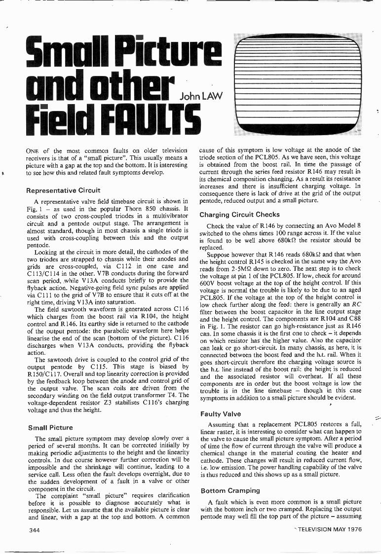
Field FAULTSONE of the most common faults on older televisionreceivers is that of a "small picture". This usually means apicture with a gap at the top and the bottom. It is interestingto see how this and related fault symptoms develop.
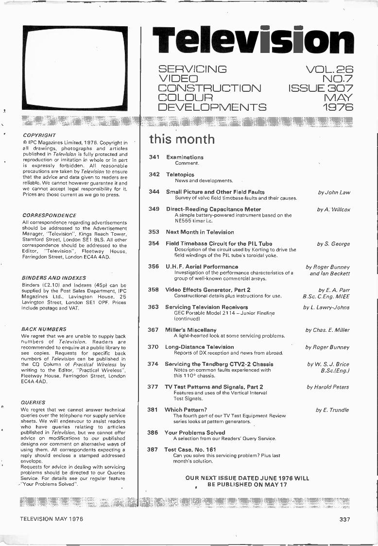
Representative CircuitA representative valve field timebase circuit is shown in
Fig. 1 - as used in the popular Thorn 850 chassis. Itconsists of two cross -coupled triodes in a multivibratorcircuit and a pentode output stage. The arrangement isalmost standard, though in most chassis a single triode isused with cross -coupling between this and the outputpentode.
Looking at the circuit in more detail, the cathodes of thetwo triodes are strapped to chassis while their anodes andgrids are cross -coupled, via C112 in one case andC 113/C114 in the other. V7B conducts during the forwardscan period, while V13A conducts briefly to provide theflyback action. Negative -going field sync pulses are appliedvia C111 to the grid of V7B to ensure that it cuts off at theright time, driving V13A into saturation.
The field sawtooth waveform is generated across C116which charges from the boost rail via R104, the heightcontrol and R146. Its earthy side is returned to the cathodeof the output pentode: the parabolic waveform here helpslinearise the end of the scan (bottom of the picture). C116discharges when V13A conducts, providing the flybackaction.
The sawtooth drive is coupled to the control grid of theoutput pentode by C115. This stage is biased byR150/C 117. Overall and top linearity correction is providedby the feedback loop between the anode and control grid ofthe output valve. The scan coils are driven from thesecondary winding on the field output transformer T4. Thevoltage -dependent resistor Z3 stabilises C116's chargingvoltage and thus the height.
Small PictureThe small picture symptom may develop slowly over a
period of several months. It can be corrected initially bymaking periodic adjustments to the height and the linearitycontrols. In due course however further correction will beimpossible and the shrinkage will continue, leading to aservice call. Less often the fault develops overnight, due tothe sudden development of a fault in a valve or othercomponent in the circuit.
The complaint "small picture" requires clarificationbefore it is possible to diagnose accurately what isresponsible. Let us assume that the available picture is clearand linear, with a gap at the top and bottom. A common
cause of this symptom is low voltage at the anode of thetriode section of the PCL805. As we have seen, this voltageis obtained from the boost rail. In time the passage ofcurrent through the series feed resistor R146 may result inits chemical composition changing. As a result its resistanceincreases and there is insufficient charging voltage. Inconsequence there is lack of drive at the grid of the outputpentode, reduced output and a small picture.
Charging Circuit Checks
Check the value of R146 by connecting an Avo Model 8switched to the ohms times 100 range across it. If the valueis found to be well above 6801(52 the resistor should bereplaced.
Suppose however that R146 reads 680162 and that whenthe height control R145 is checked in the same way the Avoreads from 2.5M52 down to zero. The next step is to checkthe voltage at pin 1 of the PCL805. If low, check for around600V boost voltage at the top of the height control. If thisvoltage is normal the trouble is likely to be due to an agedPCL805. If the voltage at the top of the height control islow check further along the feed: there is generally an RCfilter between the boost capacitor in the line output stageand the height control. The components are R104 and C88in Fig. 1. The resistor can go high -resistance just as R146can. In some chassis it is the first one to check - it dependson which resistor has the higher value. Also the capacitorcan leak or go short-circuit. In many chassis, as here, it isconnected between the boost feed and the h.t. rail. When itgoes short-circuit therefore the charging voltage source isthe h.t. line instead of the boost rail: the height is reducedand the associated resistor will overheat. If all thesecomponents are in order but the boost voltage is low thetrouble is in the line timebase - though in this casesymptoms in addition to a small picture should be evident.
Faulty Valve
Assuming that a replacement PCL805 restores a full,linear raster, it is interesting to consider what can happen tothe valve to cause the small picture symptom. After a periodof time the flow of current through the valve will produce achemical change in the material coating the heater andcathode. These changes will result in reduced current flow,i.e. low emission. The power handling capability of the valveis thus reduced and this shows up as a small picture.
Bottom Cramping
A fault which is even more common is a small picturewith the bottom inch or two cramped. Replacing the outputpentode may well fill the top part of the picture - assuming
344 TELEVISION MAY 1976
E
Videomasterurge all good electronics
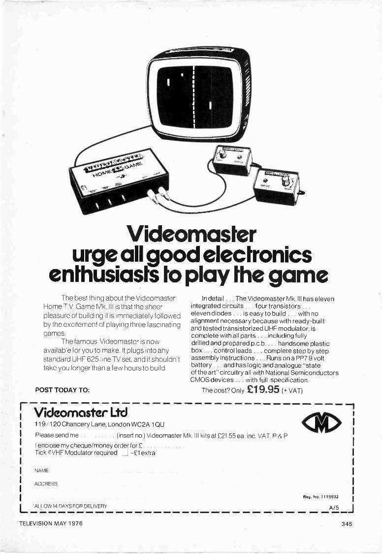
enthusiasts to play the gameThe best thing about the Videomaster
Home T.V. Game Mk. III is that the sheerpleasure of building it is immediately followedby the excitement of playing three fascinatinggames.
The famous Videomaster is nowavailable for you to make. It plugs into anystandard UHF 625 line TV set, and it shouldn'ttake you longer than a few hours to build.
POST TODAY TO:
Videomaster Ltd
In detail . . . The Videomaster Mk. III has elevenintegrated circuits . . . four transistors . . .
eleven diodes . . . is easy to build . . . with noalignment necessary because with ready -builtand tested transistorized UHF modulator, iscomplete with all parts . . . including fullydrilled and prepared p.c.b. . . . handsome plasticbox . . . control leads . . . complete step by stepassembly instructions . . . Runs on a PP7 9 voltbattery . . . and has logic and analogue "stateof the art" circuitry all with National SemiconductorsCMOS devices . . . with full specification.
The cost? Only E1 9.95 (+ VAT)
119 120 Chancery Lane, London WC2A 1QU
Please send me (insert no.) Videomaster Mk. III kits at £21.55 ea. inc. VAT. P & P
I enclose my cheque/money order for £Tick if VHF Modulator required -£1 extra
NAME
ADDRESS
L -ALLOW14 DAYS FOR DELIVERY11 lat
Reg. No. 1115532
411111, ek
TELEVISION MAY 1976 345
BRIARWOOD TELEVISION LTD.161 BROWNROYD HILL ROAD, WIBSEY, BRADFORD, WEST YORKSHIRE BD6 1RU.TEL. (0274) 671960.
PRICES QUOTED FOR QUANTITYBUYING - 100, 500, 1,000, 5,000,10,000
UPWARDS
Type Price (f) Type Price (£l Type Price (f) Type Price (E) Type Price (f) Type Price (f) Type Price (f) Type Price (£l WE OFFER
AC107 0.16 AF106 0.40 BC125 0.12 BC187 0.24 BD222 0.45 BF217 0.12 0C22 1.10 IC's FULL RANGE
AC113 0.16 AF114 0.20 BC126 0.12 BC209 0.12 BDX22 0.70 BF218 0.12 0C23 1.30 SN76013N 1.45 OF SN7400N
AC115 0.16 AF115 0.20 BC136 0.14 BC212 0.12 BDX32 1.80 BF219 0.12 0C24 1.30 SN76013ND TO SN74199N
AC117 0.23 AF116 0.20 BC137 0.14 BC213L 0.12 BDY18 0.70 BF220 0.12 0C25 0.45 1.15 SERIES IC's
AC125 0.16 AF117 0.20 BC138 0.14 BC214L 0.12 BDY60 0.70 BF222 0.12 0C26 0.40 SN76023N 1.45 eg:
AC126 0.16 AF118 0.40 BC139 0.20 BC249 0.30 BF115 0.20 BF251 0.20 0C28 0.60 SN76023N0 7400 0.16AC127 0.16 AF121 0.40 BC140 0.20 8C251 0.16 BF121 0.24 BF256 0.35 0C35 0.45 1.15 7413 0.34AC128 0.16 AF124 0.22 BC141 0.20 BC262 0.18 BF154 0.12 BF258 0.40 0C36 0.58 TBA341 0.90 7414 0.70AC131 0.12 AF125 0.20 BC142 0.22 BC263B 0.18 BF158 0.18 BF259 0.47 0C38 0.43 TBA520Q 1.60 7443 0.98AC141 0.19 AF126 0.25 , BC143 0.22 BC267 0.17 BF159 0.18 BF260 0.23 0C42 0.46 TBA530Q 1.40 7489 3.36AC141K 0.32 AF127 0.26 BC147 0.10 BC301 0.28 BF160 0.17 BF262 0.23 0C44 0.18 TBA540Q 1.60 7497 3.26AC142K 0.32 AF139 0.32 BC148 0.10 BC302 0.28 BF163 0.30 BF263 0.23 0C45 0.18 TBA560CQ 1.60 74116 1.60AC151 0.16 AF147 0.25 BC149 0.10 BC303 0.27 BF164 0.18 BF271 0.15 0C46 0.35 TBA570Q 1.60 74121 0.40AC165 0.16 AF150 0.23 BC153 0.14 BC307A 0.11 BF167 0.20 BF273 0.15 0070 0.22 TBA800 1.00 74122 0.50AC166 0.16 AF170 0.18 BC154 0.14 BC308A 0.11 BF173 0.20 BFX84 0.25 0071 0.22 TBA810 1.30 74151 1.00AC168 0.16 AF172 0.16 BC157 0.14 BC309 0.13 BF177 0.24 BFX85 0.25 0072 0.30 TBA820 0.70 74159 2.00AC176 0.16 AF178 0.50 BC158 0.13 BC547 0.10 BF178 0.30 BFX88 0.24 0074 0.35 TBA920Q 1.75 74164 1.20AC186 0.15 AF180 0.55 BC159 0.13 BC548 0.10 BF179 0.28 BFY37 0.20 0075 0.35 11349900 1.60 74192 1.20AC187 0.21 AF181 0.40 BC160 0.20 BC549 0.10 BF180 0.30 BFY51 0.23 0076 0.35 TCA270SQ 1.60 74193 1.20AC187K 0.35 AF239 0.36 BC161 0.22 BC557 0.10 BF181 0.28 BFY52 0.23 0077 0.50AC188 0.21 AL100 0.80 BC167 0.12 BD112 0.50 BF182 0.34 BFY53 0.25 0078 0.13AC188K 0.35 AL102 0.90 BC168 0.12 BD115 0.50 BF183 0.30 BFY55 0.25 0081 0.20 E.H.T. TRAYSAD130 0.40 AL112 0.80 BC169C 0.13 BD124 0.70 BF184 0.22 BHA00021.90 00810 0.14AD140 0.50 AL113 0.60 BC171 0.12 BD131 0.35 BF185 0.22 BR100 0.30 0082 0.20 MONO- COLOURAD142 0.50 BC107 0.12 BC172 0.12 BD132 0.35 BF186 0.30 BSX20 0.22 0082D 0.13 CHROME GEC 2110AD143 0.50 BC108 0.12 BC173 0.14 BD133 0.35 BF194 0.11 BSX76 0.22 0083 0.22 950 MK2 5.40AD145 0.50 BC109 0.12 BC177 0.16 50135 0.30 BF195 0.11 BSY84 0.34 0084 0.28 1400 2.15 GEC TVM 25AD149 0.50 BC113 0.10 BC178 0.16 60136 0.35 BF196 0.12 BT106 1.05 0085 0.13 150017" 19' 2.50AD161 0.43 BC114 0.10 BC179 0.16 BD137 0.35 BF197 0.12 BTX34 1.80 0C123 0.20 3 stick 2.25 Thorn 3500AD162 0.43 BC115 0.10 BC182L 0.10 60138 0.40 BF199 0.16 BU105/041.90 0C169 0.20 150024" 5.50AD161 BC116 0.12 BC183L 0.10 60139 0.40 BF200 0.28 BU126 1.50 0C170 0.22 5 stick 2.36 Deccaseries3040162 1.00I
BC117 0.12 BC184L 0.10 B0140 0.40 BF216 0.12 5U208 2.20 0C171 0.22 TH25/1HTBC119 0.20 BC186 0.24 2.50
WE HAVE MANY MORE TYPES OF TRANSISTORS, PLEASE ADD 25% VAT TO ALL ITEMS.DIODES, IC's IN STOCK OVERSEAS AT COST
P & P U.K. 12p PER ORDER. OVERSEAS ALLOW FOR ALL PRICES SUBJECT TOPACKAGE AND POSTAGE. CASH WITH ALL ORDERS. ALTERATION WITHOUT NOTICE
TV LINE OUTPUT TRANSFORMERS
ALL MAKES SUPPLIED PROMPTLY by our
RETURN OF POST MAIL ORDER SERVICE
All Lopts at the one price
£6.25 TRADEExceptBUSH MODELS TV53 to TV101.EKCO MODELS TC208 to P1417.FERGUSON MODELS 305 to 438, 506 to 546.FERRANTI MODELS 1084 to 1092.
£6.88 RETAIL (VAT. INCLUDED)Postage and Packing 55p
HMV MODELS 1876 to 1878, 1890 to 1896, FR 20.MURPHY MODELS V280 to V330, V420, V440, 653X to 789 OIL -FILLED.REGENTONE MODELS 10-4 to 10-21, 1718, R2, R3, 191, 192.RGD 519-621, 710, 711.
ALL AT £3.1 34- 55p P&P
EHT TRAYS SUPPLIED -MONO & COL.All Lopts NEW and GUARANTEED for SIX MONTHS
E. J. PAPWORTH AND SON Ltd.,80 MERTON HIGH ST., LONDON, S.W.1 9 01-540 3955
346 TELEVISION MAY 1976

405
Sync
RIBS680k
625
R136pulses 330k
C185100p
f 1364j
R13822k
V7B6-30L2
C111 31
25p
R137
C113 C11203 680p
RI3982k
R1401M
C186TLOOp
Height
51471M2
1C88
T1
V13PCL65/PCL805
R18812k
.02
Fieldhold
R1482M2
R104250k
R1154k7
R152R154 250k500k as
C117b R150
Boost voltage
HT
Field flyback1.
blanking pulses
RI61100k
360 Field tin Field lin(overall) Hop)
01191 'O1
Fig. 1: Representative valve field timebase circuit - as used in the Thorn 850 dual -standard chassis. Though many valve andhybrid chassis use two triodes in the field oscillator circuit, as here, it is more usual to use a single triode, with cross -couplingfrom the pentode which thus forms half the multivibrator circuit as well as the output stage. R185 provides height equalisationon 625 lines.
Fieldcoils
that the valve's emission was low - but the bottomcramping will still be present, and there may still be a gaphere.
There are several possible causes of this trouble but themost likely one is in the valve's cathode bias network. Thebias resistor R150 is decoupled by the 10OµF electrolyticcapacitor C117 which can deteriorate over the years. Theleads within the can may corrode where they are joined tothe plates of the capacitor. As this corrosion develops, sothe internal resistance of the capacitor gradually increases,effectively reducing its capacitance. Eventually thecorrosion will eat through the lead(s) and the capacitor willbe disconnected from the circuit, i.e. it will be open -circuit.Another electrolytic capacitor fault is 'leakage 9f theelectrolyte from the can. This again reduces its capacitance.Excessive heat from the chassis and possibly from adjacentvalves or dropper resistors can dry out an electrolyticcapacitor, again lowering its efficiency. All these faultsresult in the associated resistor no longer being effectivelydecoupled. This produces negative feedback action,reducing the pentode's gain and thus its ability to fill thescreen, particularly at the end of the scan, i.e. the bottom ofthe screen.
A quick method of checking the cathode decouplingcapacitor is to connect a known good one in parallel andnote the effect. If the raster opens out to give a normal,linear picture the capacitor is in need of replacement. Cut itout and solder in a new one.
A defective bias resistor can also contribute to thissymptom - small picture with bottom cramping. How doesthis happen? Suppose there is a heater -cathode leak in thePCL805. The severity of this will depend on the position ofthe PCL805 in the heater chain. If, which is likely, it is atthe upper end of the chain, the voltage between the heaterand chassis will be much higher than the voltage betweenthe cathode and chassis. The resultant voltage producedacross the bias resistor will be determined by the severity ofthe leak.
Linear Valve Operation
The field output valve's bias voltage is chosen so that thevalve operates on the linear portion of its grid voltage/anodecurrent characteristic curve. This ensures that the valveprovides a full, linear scan. An increase in the bias voltage
produced by a heater -cathode leak will move the valve'soperating point along its characteristic curve, limiting thevalve's power handling capacity. The visible result isreduced scan with cramping, the degree of which will bedetermined by the amount of leakage.
Bias Circuit ChecksReplacing the valve may well completely cure the fault. If
not, check the appearance of the bias resistor. It may bediscoloured or even burnt. If so, check its value with theAvometer switched to read ohms. It will probably be foundthat the value has changed. As we have seen the fault startswith heater -cathode leakage in the valve, as a result ofwhich the voltage across the resistor is increased. As weknow from Ohm's Law, this will increase the currentthrough the resistor and the heat it dissipates. Eventuallythe dissipation will exceed the resistor's wattage rating, withthe result that it overheats and its resistance value changes.Whether the resistor increases or decreases in value (itgenerally decreases) the result will be that the valve's biasvoltage moves away from the correct point along its charac-teristic curve, reducing its power handling capacity andcausing bottom cramping. The effect of a slight increase invalue will be more noticeable at the top of the rasterhowever.
Even if a new valve completely cures the fault it is worthchecking the resistor. If it has changed value due to a slightleak in the previous valve the life of the new one will beshorter than it should be.
Leaky Capacitors
We have not yet exhausted the possible causes of thissymptom however. Consider the PCL805's control gridcircuit. The voltage here is normally negative with respect toits cathode and the value is chosen to ensure a full, linearscan. If there is a leak in the coupling capacitor C115however some of the positive voltage at the triode anode willappear at the pentode's control grid, reducing the negativegrid voltage and once again moving the valve's operatingpoint along the characteristic curve. The symptoms in thiscase may not be confined to bottom cramping but mayextend to a complete foldover of the scan over the bottominch or two of the raster.
TELEVISION MAY 1976 347
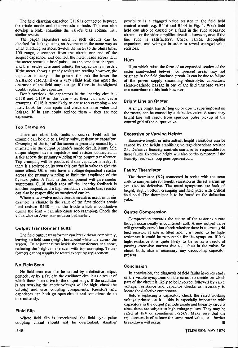
The field charging capacitor C116 is connected betweenthe triode anode and the pentode cathode. This can alsodevelop a leak, changing the valve's bias voltage withsimilar results.
The paper capacitors used in such circuits can bechecked for leakage using an Avometer in the same way aswhen checking resistors. Switch the meter to the ohms times100 range, disconnect from the circuit one end of thesuspect capacitor, and connect the meter leads across it. Ifthe meter records a brief pulse - as the capacitor charges -and then settles at around infinity the capacitor is in order.If the meter shows a steady resistance reading however, thecapacitor is leaky - the greater the leak the lower theresistance reading. Even a very slight leak can upset theoperation of the field output stage: if there is the slightestdoubt, replace the capacitor.
Don't overlook the capacitors in the linearity circuit -C118 and C119 in this case - as these can also causecramping. C118 is more likely to cause top cramping - seelater. Look for burn spots and check them for value andleakage. If in any doubt replace them - they are notexpensive.
Top Cramping
There are other field faults of course. Field roll forexample can be due to a faulty valve, resistor or capacitor.Cramping at the top of the screen is generally caused by amismatch in the output pentode's anode circuit. Many fieldoutput stages have a capacitor and resistor connected inseries across the primary winding of the output transformer.Top cramping will be produced if this capacitor is leaky. Ifthere is a resistor on its own this can fall in value to give thesame effect. Other sets have a voltage -dependent resistoracross the primary winding to limit the amplitude of theflyback pulse. A fault in this component will give similarsymptoms. C118 which taps off the linearity feedback isanother suspect, and a high -resistance cathode bias resistorcan also be responsible as mentioned earlier.
Where a two -valve multivibrator circuit is used, as in ourexample, a change in the value of the first triode's anodeload resistor R138 - i.e. the triode which is conductiveduring the can - can also cause top cramping. Check thevalue with an Avometer as described earlier.
Output Transformer FaultsThe field output transformer can break down completely,
leaving no field scan (bright horizontal white line across thescreen). Or adjacent turns inside the transformer can short,reducing the height of the scan with top cramping. Trans-formers cannot usually be tested except by replacement.
No Field Scan
No field scan can also be caused by a defective outputpentode, or by a fault in the oscillator circuit as a result ofwhich there is no drive to the output stage. If the oscillatoris not working the anode voltages will be high: check thevalve(s) and cross -coupling components. Resistors andcapacitors can both go open -circuit and sometimes do sointermittently.
Field Slip
Where field slip is experienced the field sync pulsecoupling circuit should not be overlooked. Another
possibility is a changed value resistor in the field holdcontrol circuit, e.g. R116 and R144 in Fig. 1. Weak fieldhold can also be caused by a fault in the sync separatorcircuit - or the video amplifier circuit - however, even if theline sync is satisfactory. Check valves, decouplingcapacitors, and voltages in order to reveal changed valueresistors.
Hum
Hum which takes the form of an expanded section of theraster sandwiched between compressed areas may notoriginate in the field timebase circuit. It can be due to failureof the power supply smoothing electrolytic capacitors.Heater -cathode leakage in one of the field timebase valvescan contribute to this fault however.
Bright Line on Raster
A single bright line drifting up or down, superimposed onthe raster, can be caused by a defective valve. A stationarybright line will result from spurious pulse pickup at thecontrol grid of the output valve.
Excessive or Varying HeightExcessive height or intermittent height variations can be
caused by the height stabilising voltage -dependent resistorZ3. Defective linearity controls can also be responsible forthese faults. Excessive height will also be the symptom if thelinearity feedback loop goes open -circuit.
Faulty ThermistorThe thermistor (X2) connected in series with the scan
coils to compensate for height variation as the set warms upcan also be defective. The usual symptoms are lack ofheight, slight bottom cramping and field jitter with criticalfield hold. The thermistor is to be found on the deflectionyoke.
Centre CompressionCompression towards the centre of the raster is a rare
though occasionally encountered fault. A new output valvewill generally cure it but check whether there is a screen gridfeed resistor. If one is fitted and it is found to be high -resistance it could be responsible for the symptom. If it ishigh -resistance it is quite likely to be so as a result ofpassing excessive current due to a fault in the valve. Socheck both, also if necessary any decoupling capacitorpresent.
Conclusion
In conclusion, the diagnosis of field faults involves studyof the visible symptoms on the screen to decide on whichpart of the circuit is likely to be involved, followed by valve,voltage, resistance and capacitor checks as necessary tolocate the defective component.
Before replacing a capacitor, check the rated workingvoltage printed on it - this is especially important withcapacitors in the output pentode anode and linearity circuitssince these are subject to high -voltage pulses. They may berated at 1 kV or sometimes 1.25kV. Make sure that thereplacement is of at least the same rated value, or a furtherbreakdown will occur.
348 TELEVISION MAY 1976
DIRECT~READING
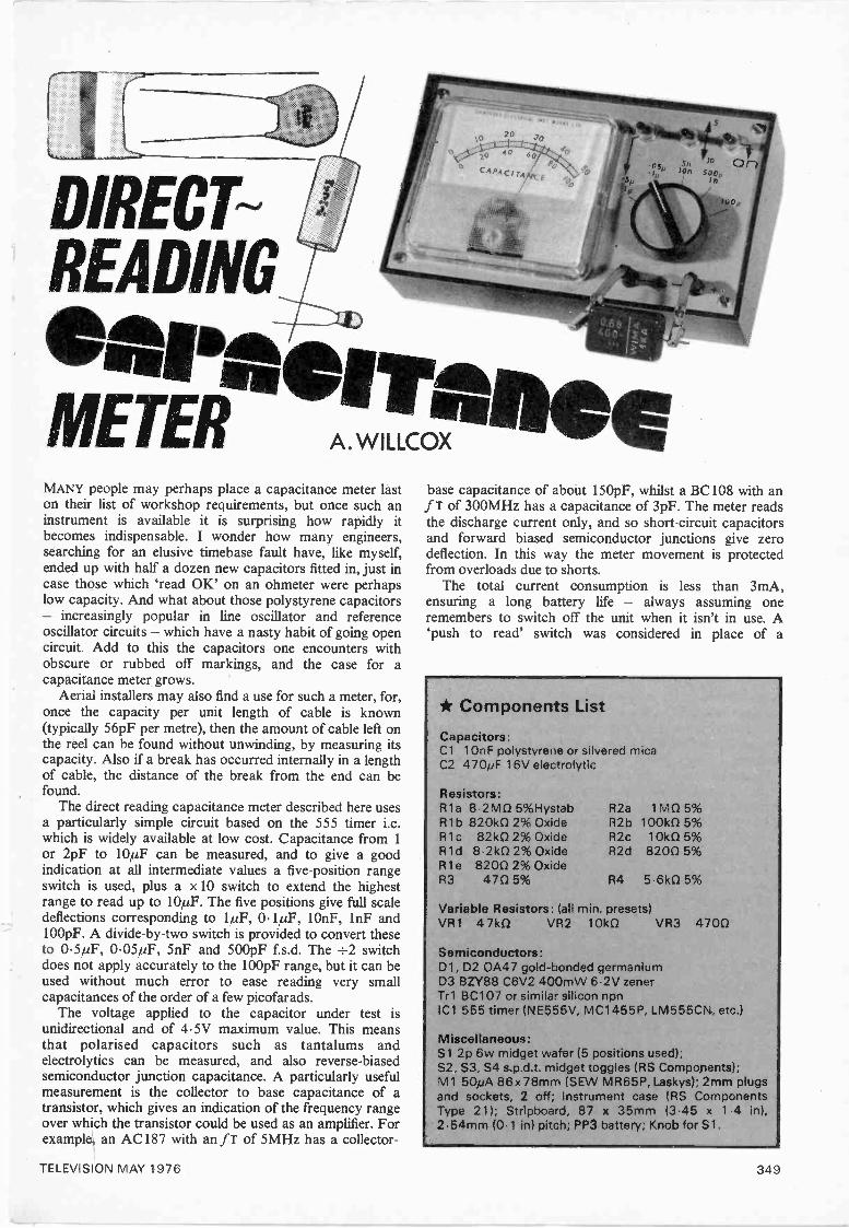
eareenIft.,METER .,,,co,!'wxwaMANY people may perhaps place a capacitance meter laston their list of workshop requirements, but once such aninstrument is available it is surprising how rapidly itbecomes indispensable. I wonder how many engineers,searching for an elusive timebase fault have, like myself,ended up with half a dozen new capacitors fitted in, just incase those which 'read OK' on an ohmeter were perhapslow capacity. And what about those polystyrene capacitors- increasingly popular in line oscillator and referenceoscillator circuits - which have a nasty habit of going opencircuit. Add to this the capacitors one encounters withobscure or rubbed off markings, and the case for acapacitance meter grows.
Aerial installers may also find a use for such a meter, for,once the capacity per unit length of cable is known(typically 56pF per metre), then the amount of cable left onthe reel can be found without unwinding, by measuring itscapacity. Also if a break has occurred internally in a lengthof cable, the distance of the break from the end can befound.
The direct reading capacitance meter described here usesa particularly simple circuit based on the 555 timer i.c.which is widely available at low cost. Capacitance from 1or 2pF to 10µF can be measured, and to give a goodindication at all intermediate values a five -position rangeswitch is used, plus a x 10 switch to extend the highestrange to read up to 10µF. The five positions give full scaledeflections corresponding to 1µF, 0.1,uF, lOnF, 1nF and100pF. A divide -by -two switch is provided to convert theseto 0.5µF, 0.05µF, 5nF and 500pF f.s.d. The ÷2 switchdoes not apply accurately to the 100pF range, but it can beused without much error to ease reading very smallcapacitances of the order of a few picofarads.
The voltage applied to the capacitor under test isunidirectional and of 4.5V maximum value. This meansthat polarised capacitors such as tantalums andelectrolytics can be measured, and also reverse -biasedsemiconductor junction capacitance. A particularly usefulmeasurement is the collector to base capacitance of atransistor, which gives an indication of the frequency rangeover which the transistor could be used as an amplifier. Forexample, an AC187 with an fr of 5MHz has a collector -
base capacitance of about 150pF, whilst a BC108 with anfT of 300MHz has a capacitance of 3pF. The meter readsthe discharge current only, and so short-circuit capacitorsand forward biased semiconductor junctions give zerodeflection. In this way the meter movement is protectedfrom overloads due to shorts.
The total current consumption is less than 3mA,ensuring a long battery life - always assuming oneremembers to switch off the unit when it isn't in use. A`push to read' switch was considered in place of a
* Components ListCapacitors:Cl 10nF polystyrene or silvered micaC2 470pF 16V electrolytic
Resistors:R la 8 2M0 5%Hystab R2a 1 MO 5%R1b 820k0 2% Oxide R2b 1001(0 5%R1c 82k0 2% Oxide R2c 10k0 5%R1d 821(0 2% Oxide R2d 8200 5%R1e 8200 2% OxideR3 470 5% R4 5.6k0 5%
Variable Resistors: (all min, presets)VR1 47k0 VR2 10k0 VR3 4700
Semiconductors:D1, D2 0A47 gold -bonded germaniumD3 BZY88 C6V2 400mW 6 2V zenerTr1 BC107 or similar silicon npnIC1 555 timer (NE555V, MC1455P, LM555CN., etc.)
Miscellaneous:S1 2p 6w midget wafer (5 positions used);S2, S3, S4 s.p.d.t. midget toggles (RS Components);M1 50pA 86x 78mm (SEW MR65P, Laskys); 2mm plugsand sockets, 2 off; Instrument case (RS ComponentsType 21); Stripboard, 87 x 35mm (3.45 x 1 4 in),2.54mm (0.1 in) pitch; PP3 battery; Knob for Si.
TELEVISION MAY 1976 349
R1
R2
+5V
6 Vcc 4 Reset
7
Discharge
6
Dischargeswitch
0 52
Comparator 1
Threshold
2
2/3Vcc
Comparator 2
Trigger
C1
Bi-stable
51
1/3VCC
2
.5Control
D2
CX
1
Outputswitch
1 Ground
conventional on/off switch, but this was rejected in casethere was an occasion for a reading to be observed over aperiod, perhaps while the effect of temperature changes onthe capacitor were noted.
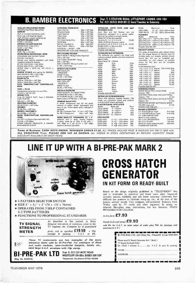
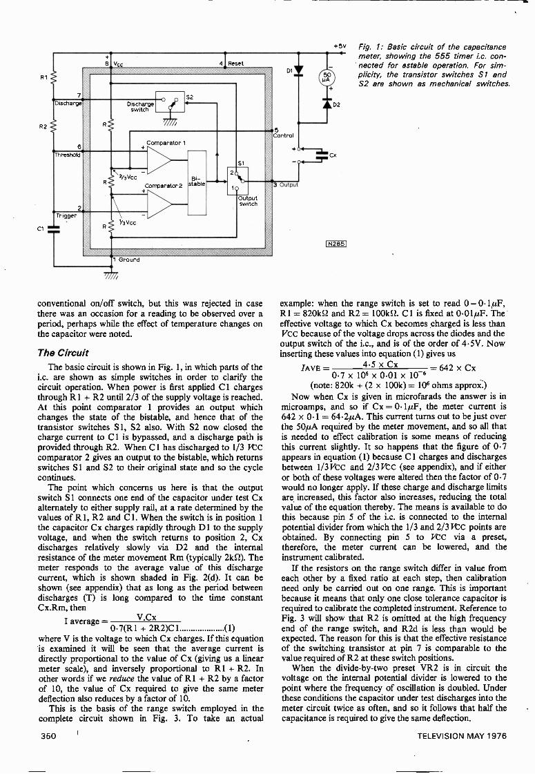
The CircuitThe basic circuit is shown in Fig. 1, in which parts of the
i.c. are shown as simple switches in order to clarify thecircuit operation. When power is first applied C 1 chargesthrough R1 + R2 until 2/3 of the supply voltage is reached.At this point comparator 1 provides an output whichchanges the state of the bistable, and hence that of thetransistor switches S 1, S2 also. With S2 now closed thecharge current to Cl is bypassed, and a discharge path isprovided through R2. When Cl has discharged to 1/3 VCCcomparator 2 gives an output to the bistable, which returnsswitches S1 and S2 to their original state and so the cyclecontinues.
The point which concerns us here is that the outputswitch S1 connects one end of the capacitor under test Cxalternately to either supply rail, at a rate determined by thevalues of R 1, R2 and C 1. When the switch is in position 1the capacitor Cx charges rapidly through D1 to the supplyvoltage, and when the switch returns to position 2, Cxdischarges relatively slowly via D2 and the internalresistance of the meter movement Rm (typically 21(52). Themeter responds to the average value of this dischargecurrent, which is shown shaded in Fig. 2(d). It can beshown (see appendix) that as long as the period betweendischarges (T) is long compared to the time constantCx.Rm, then
I average = V.Cx0.7(R1 + 2R2)C 1 (1)
where V is the voltage to which Cx charges. If this equationis examined it will be seen that the average current isdirectly proportional to the value of Cx (giving us a linearmeter scale), and inversely proportional to R1 + R2. Inother words if we reduce the value of R1 + R2 by a factorof 10, the value of Cx required to give the same meterdeflection also reduces by a factor of 10.
This is the basis of the range switch employed in thecomplete circuit shown in Fig. 3. To take an actual
3 Output
1N2851
Fig. 1: Basic circuit of the capacitancemeter, showing the 555 timer i.c. con-nected for astable operation. For sim-plicity, the transistor switches Si andS2 are shown as mechanical switches.
example: when the range switch is set to read 0 -R1 = 820E2 and R2 = 100k52. Cl is fixed at 0.01µF. Theeffective voltage to which Cx becomes charged is less thanVcc because of the voltage drops across the diodes and theoutput switch of the i.c., and is of the order of 4.5V. Nowinserting these values into equation (1) gives us
4.5 x CxLAVE= = 642 x Cx0.7 x 106 x 0.01 x 10-6
(note: 820k + (2 x 100k) = 106 ohms approx.)Now when Cx is given in microfarads the answer is in
microamps, and so if Cx = 0.1µF, the meter current is642 x 0.1 = 64.2yA. This current turns out to be just overthe 50µA required by the meter movement, and so all thatis needed to effect calibration is some means of reducingthis current slightly. It so happens that the figure of 0.7appears in equation (1) because C 1 charges and dischargesbetween 1/3 VCC and 2/3 VCC (see appendix), and if eitheror both of these voltages were altered then the factor of 0.7would no longer apply. If these charge and discharge limitsare increased, this factor also increases, reducing the totalvalue of the equation thereby. The means is available to dothis because pin 5 of the i.c. is connected to the internalpotential divider from which the 1/3 and 2/3 Vcc points areobtained. By connecting pin 5 to VCC via a preset,therefore, the meter current can be lowered, and theinstrument calibrated.
If the resistors on the range switch differ in value fromeach other by a fixed ratio at each step, then calibrationneed only be carried out on one range. This is importantbecause it means that only one close tolerance capacitor isrequired to calibrate the completed instrument. Reference toFig. 3 will show that R2 is omitted at the high frequencyend of the range switch, and R2d is less than would beexpected. The reason for this is that the effective resistanceof the switching transistor at pin 7 is comparable to thevalue required of R2 at these switch positions.
When the divide -by -two preset VR2 is in circuit thevoltage on the internal potential divider is lowered to thepoint where the frequency of oscillation is doubled. Underthese conditions the capacitor under test discharges into themeter circuit twice as often, and so it follows that half thecapacitance is required to give the same deflection.
350 TELEVISION MAY 1976

V
Vcc
2/3 Vcc
Vcc
Vcc
VccV
I max_ V
Meterresistance(
I ---4.
--, ti 14- t2
V
(a)
(b)
o
.4-1
Charge --------current
(c)
Cx.R
2)
Dc ui srcrheanT eT
f,4%
10.
1N2861
Fig. 2: (a) Voltage across Cl from switch -on. (b) Outputvoltage of i.c. at pin 3. (c) Voltage across the test capacitorCx. (d) Current through Cx. The shaded area is the currentmeasured by the meter.
The x 10 circuit functions by shunting 9/10 of Cx'sdischarge current around the meter, so raising by a factorof 10 the value of Cx required to give the same deflection.Due to the low frequency of the oscillator on the 1µF rangesome fluctuation of the meter pointer is evident, and soadvantage of the x 10 switch is taken to introduce asmoothing capacitor across the meter movement.
82k
51 4 3 2
5
Fig. 3: Complete circuit of the capaci-tance meter. The arrows against thepreset potentiometers indicate directionof movement with clockwise rotation.
R1 e8202%
Rid8.2k25
4 3 2
820Rai
R2c10k
C110nF
APPENDIX
The time between successive discharges of Cx (Fig. 2(d)) is equal tot, + t2 (Fig. 2(a)).
To find t,Now t, is the time taken for C1 to discharge from Vcc to }Vcc.That is, to lose one half of its voltage. The fall in voltage is given byVt=Vo.e -t/C1 R2 where Vt is the voltage across C1 after an intervalt, & Vo is the initial voltage. This may be written
Vo/Vt_et/C1R2
or log Aci=t/C1R2
from whence t=C1 R1 loge VoNt
Now VoNt in this case is jVcc,/+Vc2and sot, =C1 R2 loge2=0.6931 C1 R2
CI-7C1R2 approximately
To find t2Just as the time taken for a capacitor to lose one half of its chargewas found to be 0.7 x the time constant, so the time taken for acapacitor to charge to halfway between its initial and final values isalso 0.7CR. Reference to Fig. 2(a) will show that this is the case withthe interval t2. As C1 charges from its initial value of I Vcc to thefinal value of Vcc, the charge is halted at the halfway point 4 Vcc. Inthis case, however, C1 charges via R1 and R2 in series and sot2=0.7 (R1+R2)C1.The total cycle time T=t, +tz=0.7 C1R2+0-71R1÷R21C1
=0.7(R1+2R2)C1Turning now to Cx, the average discharge current is the area under
the curve (shaded in Fig. 2(d)) divided by the base line T.If R=the discharge resistance provided by the meter movement and
nCxR=T then nCxR
foI ave=nCxR
or I ave.=kImaxf n/k
Imax.e -t/CxR dt
e-kt dt
kimax [ e-kt ] nil(n k 0
k.lmax (-e -n _teo
n k_Imax (1 1 )
n en
where k= 1
CxR
If however T is large compared to CxR, becomes so small that it
can be ignored giving lave= Imnax
Now Imax=1/ where V is the voltage to which Cx charges so
lave=Rn eq(1)
As T=nCxR=0.71131+2R21C1 so n= 0.7(R1+2R2) C1Cx. R
substituting this value of n in eq(1) givesVlave= V. Cx
0-7)R1 +2R2) C1
2 x 0.447
R45.6k
D36.2Vzener
+9V
0
1N2671
TELEVISION MAY 1976 351
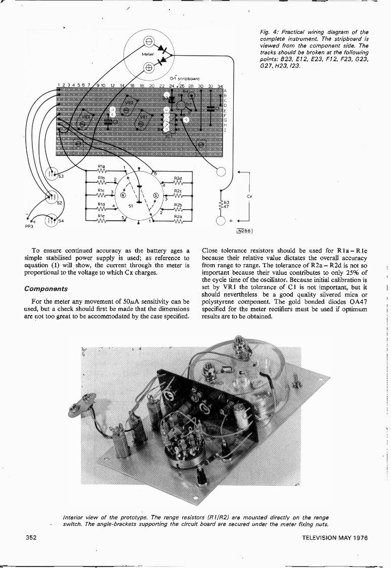
To ensure continued accuracy as the battery ages asimple stabilised power supply is used; as reference toequation (1) will show, the current through the meter isproportional to the voltage to which Cx charges.
Components
For the meter any movement of 50µA sensitivity can beused, but a check should first be made that the dimensionsare not too great to be accommodated by the case specified.
Fig. 4: Practical wiring diagram of thecomplete instrument. The stripboard isviewed from the component side. Thetracks should be broken at the followingpoints: B23, E12, E23, F12, F23, G23,G27, H23,123.
Cx
IN2881
Close tolerance resistors should be used for Rla-R lebecause their relative value dictates the overall accuracyfrom range to range. The tolerance of R2a - R2d is not soimportant because their value contributes to only 25% ofthe cycle time of the oscillator. Because initial calibration isset by VR I the tolerance of C1 is not important, but itshould nevertheless be a good quality silvered mica orpolystyrene component. The gold bonded diodes 0A47specified for the meter rectifiers must be used if optimumresults are to be obtained.
Interior view of the prototype. The range resistors (R111321 are mounted directly on the rangeswitch. The angle -brackets supporting the circuit board are secured under the meter fixing nuts.
352 TELEVISION MAY 1976
Calibration
If the meter movement used has a single scale marking, itwill be necessary to remove the front panel and add anotherset of scale markings to avoid a mental multiplication ordivision by two when the +2 switch is operated. With themovement specified in the components list it is a simplematter to prise off the front cover, and to remove the twoscrews holding the scale in position. The scale can then becarefully removed and an additional range added as shownin the illustrations. When replacing the cover, care must betaken to engage the set zero mechanism correctly. Wheninterpreting the meter reading, the top scale of the meterand range switch applies with the +2 switch up, and thelower scale with the switch down.
Before switch -on the presets should be set to nearminimum position (anticlockwise). The instrument can becalibrated on any range, but close tolerance capacitors aremore readily available in the lower values. Assuming a1000pF 1% capacitor is used, this should be connected tothe test terminals, and the range switch set to the In/500pFposition. The +2 switch should be down (out of circuit) andthe instrument then switched on. VR1 is now advanceduntil the meter reads full scale deflection.
In order to set the +2 circuit the range switch should firstbe turned to the 10n/5n position, then the +2 switchoperated (up position). VR2 should be advanced until themeter reads 10 on the 0-50 scale. Alternatively, if a 500pFcapacitor is also available, the +2 preset can be adjusted togive f.s.d. on the ln/500pF range. As explained below thex 10 switch is used only on the 1/0.5µF and 0.1/0.05µFpositions of the range switch, and due to frequencyrestrictions the x 10 preset must be set up on these ranges.A close tolerance component is not required, however, anda capacitor of around 0.47,uF is ideal. With the range and+2 switches set to read 0-0.5µF, the value of the capacitorshould be read and noted. The x 10 switch is now operated,and the range switch set to read 0-0-05µF. VR3 is nowadvanced until the same deflection as before is obtained.Calibration is now complete, and the instrument ready foruse.
Using the Instrument
As explained before, the meter pointer will be subject tosome vibration on the 1/0.5,uF ranges. To overcome thisthe 0.1/0.05 range can be used in conjunction with the x 10switch to fulfil the function normally provided by the 1/0.5range. And so the highest range would only be used withthe x 10 switch operated, in order to read 5 or 10µF f.s.d.In this way maximum use is made of the extra smoothingadded when the x 10 switch is on. Short circuit capacitorswill give a zero reading, while a leaky component will readlow capacity.
Semiconductor junctions will read their capacity at 4.5Vwhen reverse biased, and zero when forward biased. Forexample, the BA102 varicap diode, used in referenceoscillator circuits, can be tested and should read around40pF.
SafetyThe only way in which the meter movement can be
overloaded is if a large capacity is connected while therange switch is in a low capacity position. For this reasonthe switch is arranged so that one would logically start atthe highest range and rotate the switch clockwise until areasonable deflection is obtained.
Television SERVICING THE DECCA 10/30
SERIES CHASSISThe Decca Bradford chassis was first released in 1970and is still in production. It is one of the best knownhybrid colour chassis and large numbers have been soldand rented. Next month we start a detailed survey of thechassis, the faults to be expected, and fault-findingprocedures, dealing with both the 10 and 30 versions.
SIMPLE GREY -SCALE GENERATORThree 74 -series TTL i.c.s and two transistors are used togenerate an eight -step wedge suitable for injection intothe video or luminance stages. The circuit can bemodified to match either the BBC or the IBA colour barstandards.
THYRISTOR LINE OUTPUT STAGESAll line output stages work on the same basic principlebut the thyristor circuit at first glance appears to besomething entirely different. Because of thecharacteristics of thyristors, there is added complexity,though the circuit still performs the same basicoperations. We shall be examining the principles, thedifferences between thyristor and transistor circuits, andpractical arrangements.
SERVICING TELEVISIONRECEIVERS
Les Lawry -Johns describes his experiences with the Pyegroup's 173 chassis which superseded the 169 in 1973.
VIDEOTAPE COPYINGVivian Capel reviews various techniques currentlyavailable for producing multiple copies of videotapedmaterial.
PLUS ALL THE REGULAR FEATURES
ORDER YOUR COPY ON THE FORM BELOW
TO(Name of Newsagent)
Please reserve/deliver the JUNE issue ofTELEVISION (40p), on sale May 17th, andcontinue every month until further notice.
NAME
ADDRESS
L J
TELEVISION MAY 1976 353
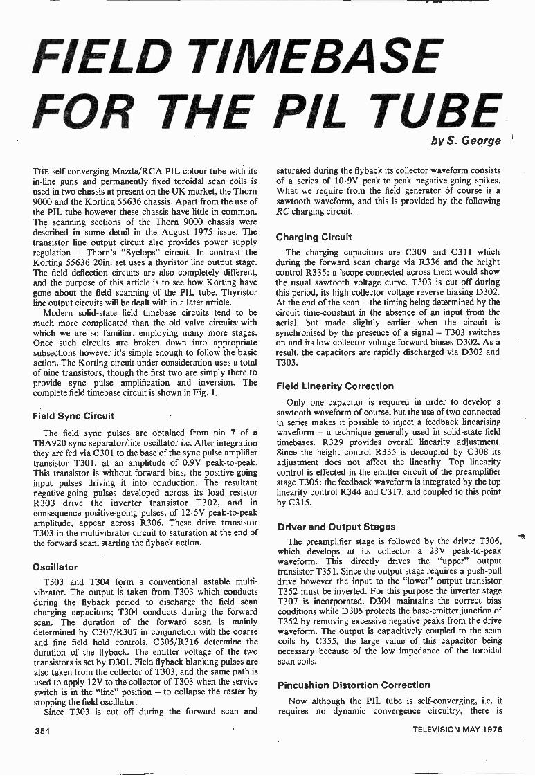
FIELD TIMEBASEFOR THE PIL TUBETHE self -converging Mazda/RCA PIL colour tube with itsin -line guns and permanently fixed toroidal scan coils isused in two chassis at present on the UK market, the Thorn9000 and the Korting 55636 chassis. Apart from the use ofthe PIL tube however these chassis have little in common.The scanning sections of the Thorn 9000 chassis weredescribed in some detail in the August 1975 issue. Thetransistor line output circuit also provides power supplyregulation - Thorn's "Syclops" circuit. In contrast theKorting 55636 20in. set uses a thyristor line output stage.The field deflection circuits are also completely different,and the purpose of this article is to see how Korting havegone about the field scanning of the PIL tube. Thyristorline output circuits will be dealt with in a later article.
Modern solid-state field timebase circuits tend to bemuch more complicated than the old valve circuits withwhich we are so familiar, employing many more stages.Once such circuits are broken down into appropriatesubsections however it's simple enough to follow the basicaction. The Korting circuit under consideration uses a totalof nine transistors, though the first two are simply there toprovide sync pulse amplification and inversion. Thecomplete field timebase circuit is shown in Fig. 1.
Field Sync Circuit
The field sync pulses are obtained from pin 7 of aTBA920 sync separator/line oscillator i.c. After integrationthey are fed via C301 to the base of the sync pulse amplifiertransistor T301, at an amplitude of 0.9V peak -to -peak.This transistor is without forward bias, the positive -goinginput pulses driving it into conduction. The resultantnegative -going pulses developed across its load resistorR303 drive the inverter transistor T302, and inconsequence positive -going pulses, of 12.5V peak -to -peakamplitude, appear across R306. These drive transistorT303 in the multivibrator circuit to saturation at the end ofthe forward scan, starting the flyback action.
OscillatorT303 and T304 form a conventional astable multi -
vibrator. The output is taken from T303 which conductsduring the flyback period to discharge the field scancharging capacitors; T304 conducts during the forwardscan. The duration of the forward scan is mainlydetermined by C307/R307 in conjunction with the coarseand fine field hold controls. C305/R316 determine theduration of the flyback. The emitter voltage of the twotransistors is set by D301. Field flyback blanking pulses arealso taken from the collector of T303, and the same path isused to apply 12V to the collector of T303 when the serviceswitch is in the "line" position - to collapse the raster bystopping the field oscillator.
Since T303 is cut off during the forward scan and
by S. George
saturated during the flyback its collector waveform consistsof a series of 10.9V peak -to -peak negative -going spikes.What we require from the field generator of course is asawtooth waveform, and this is provided by the followingRC charging circuit.
Charging CircuitThe charging capacitors are C309 and C311 which
during the forward scan charge via R336 and the heightcontrol R335: a 'scope connected across them would showthe usual sawtooth voltage curve. T303 is cut off duringthis period, its high collector voltage reverse biasing D302.At the end of the scan - the timing being determined by thecircuit time -constant in the absence of an input from theaerial, but made slightly earlier when the circuit issynchronised by the presence of a signal - T303 switcheson and its low collector voltage forward biases D302. As aresult, the capacitors are rapidly discharged via D302 andT303.
Field Linearity Correction
Only one capacitor is required in order to develop asawtooth waveform of course, but the use of two connectedin series makes it possible to inject a feedback linearisingwaveform - a technique generally used in solid-state fieldtimebases. R329 provides overall linearity adjustment.Since the height control R335 is decoupled by C308 itsadjustment does not affect the linearity. Top linearitycontrol is effected in the emitter circuit of the preamplifierstage T305: the feedback waveform is integrated by the toplinearity control R344 and C317, and coupled to this pointby C315.
Driver and Output StagesThe preamplifier stage is followed by the driver T306,
which develops at its collector a 23V peak -to -peakwaveform. This directly drives the "upper" outputtransistor T351. Since the output stage requires a push-pulldrive however the input to the "lower" output transistorT352 must be inverted. For this purpose the inverter stageT307 is incorporated. D304 maintains the correct biasconditions while D305 protects the base -emitter junction ofT352 by removing excessive negative peaks from the drivewaveform. The output is capacitively coupled to the scancoils by C355, the large value of this capacitor beingnecessary because of the low impedance of the toroidalscan coils.
Pincushion Distortion Correction
Now although the PIL tube is self -converging, i.e. itrequires no dynamic convergence circuitry, there is
354 TELEVISION MAY 1976
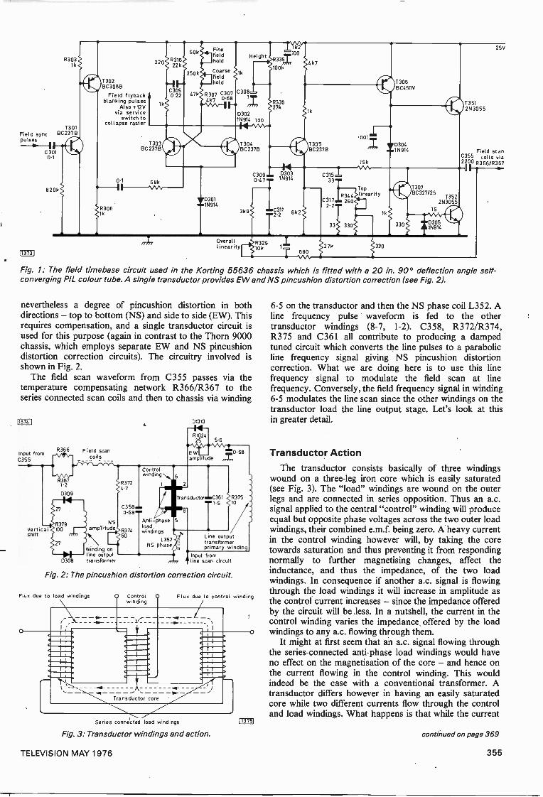
R3031k
T301Field sync BC237B
C3010.1
820k
113731
T302BC308B
Field flybackblanking pulses
Also +12Vvia service
switch tocollapse raster
01
11,306
220
T303BC237B
1N914 100
BC237B
1k2100
R33Z
1N914
BC237B
T306BC460V
0304N914
T307
II
BC327/25R344 135211,0301 I C317 250 2N3055
25V
©1351
wf.1N914
Overalllinearity
C311 8k22.2
27k
Toplinearity
1N914
2N3055
Field scanC355 coils via2200 R3. 66/R367
Fig. 1: The field timebase circuit used in the Korting 55636 chassis which is fitted with a 20 in. 90° deflection angle self-converging PIL colour tube. A single transductor provides EW and NS pincushion distortion correction (see Fig. 21.
nevertheless a degree of pincushion distortion in bothdirections - top to bottom (NS) and side to side (EW). Thisrequires compensation, and a single transductor circuit isused for this purpose (again in contrast to the Thorn 9000chassis, which employs separate EW and NS pincushiondistortion correction circuits). The circuitry involved isshown in Fig. 2.
The field scan waveform from C355 passes via thetemperature compensating network R366/R367 to theseries connected scan coils and then to chassis via winding
11374 1
Input fromC355
Verticalshift
R366
R3671.2
D309
Field scancoils
01010
R102/..25
EWamplitude
5'6
79 NSamplitude
Winding online output
D308 transformer
R37247
C3580.68
R37460
Controlwinding
Anti -phaseloadwindings
L352NS phase
Transductor C3611.5
0.68
R37510
L ne outputt ansformerprimary winding
Input fromline scan circuit
Fig. 2: The pincushion distortion correction circuit.
Flux due to load windings Controlwinding
Flux due to control winding
Series connected load windings
Fig. 3: Transductor windings and action.
113751
6-5 on the transductor and then the NS phase coil L352. Aline frequency pulse waveform is fed to the othertransductor windings (8-7, 1-2). C358, R372/R374,R375 and C361 all contribute to producing a dampedtuned circuit which converts the line pulses to a parabolicline frequency signal giving NS pincushion distortioncorrection. What we are doing here is to use this linefrequency signal to modulate the field scan at linefrequency. Conversely, the field frequency signal in winding6-5 modulates the line scan since the other windings on thetransductor load the line output stage. Let's look at thisin greater detail.
Transductor ActionThe transductor consists basically of three windings
wound on a three -leg iron core which is easily saturated(see Fig. 3). The "load" windings are wound on the outerlegs and are connected in series opposition. Thus an a.c.signal applied to the central "control" winding will produceequal but opposite phase voltages across the two outer loadwindings, their combined e.m.f. being zero. A heavy currentin the control winding however will, by taking the coretowards saturation and thus preventing it from respondingnormally to further magnetising changes, affect theinductance, and thus the impedance, of the two loadwindings. In consequence if another a.c. signal is flowingthrough the load windings it will increase in amplitude asthe control current increases - since the impedance offeredby the circuit will be less. In a nutshell, the current in thecontrol winding varies the impedance offered by the loadwindings to any a.c. flowing through them.
It might at first seem that an a.c. signal flowing throughthe series -connected anti -phase load windings would haveno effect on the magnetisation of the core - and hence onthe current flowing in the control winding. This wouldindeed be the case with a conventional transformer. Atransductor differs however in having an easily saturatedcore while two different currents flow through the controland load windings. What happens is that while the current
continued on page 369
TELEVISION MAY 1976 355
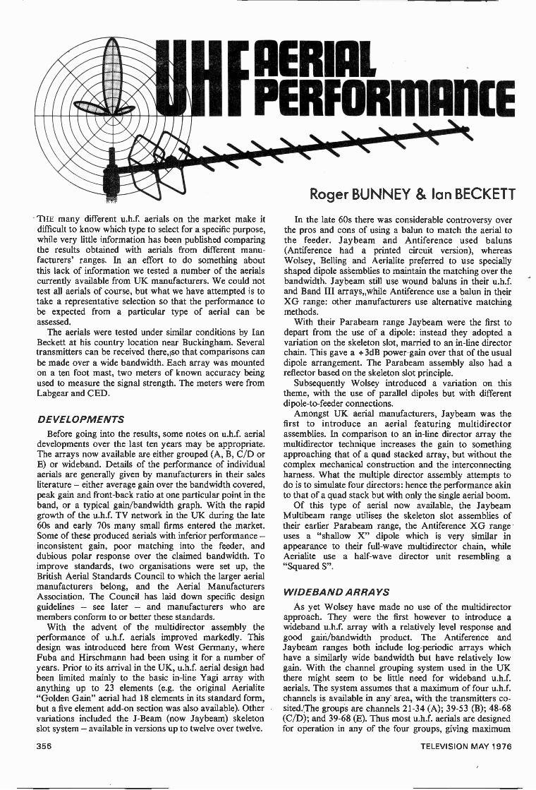
[AERIALi PERFORMANCE
THE many different u.h.f. aerials on the market make itdifficult to know which type to select for a specific purpose,while very little information has been published comparingthe results obtained with aerials from different manu-facturers' ranges. In an effort to do something aboutthis lack of information we tested a number of the aerialscurrently available from UK manufacturers. We could nottest all aerials of course, but what we have attempted is totake a representative selection so that the performance tobe expected from a particular type of aerial can beassessed.
The aerials were tested under similar conditions by IanBeckett at his country location near Buckingham. Severaltransmitters can be received there,lso that comparisons canbe made over a wide bandwidth. Each array was mountedon a ten foot mast, two meters of known accuracy beingused to measure the signal strength. The meters were fromLabgear and CED.
DEVELOPMENTSBefore going into the results, some notes on u.h.f. aerial
developments over the last ten years may be appropriate.The arrays now available are either grouped (A, B, C/D orE) or wideband. Details of the performance of individualaerials are generally given by manufacturers in their salesliterature - either average gain over the bandwidth covered,peak gain and front -back ratio at one particular point in theband, or a typical gain/bandwidth graph. With the rapidgrowth of the u.h.f. TV network in the UK during the late60s and early 70s many small firms entered the market.Some of these produced aerials with inferior performance -inconsistent gain, poor matching into the feeder, anddubious polar response over the claimed bandwidth. Toimprove standards, two organisations were set up, theBritish Aerial Standards Council to which the larger aerialmanufacturers belong, and the Aerial ManufacturersAssociation. The Council has laid down specific designguidelines - see later - and manufacturers who aremembers conform to or better these standards.
With the advent of the multidirector assembly theperformance of u.h.f. aerials improved markedly. Thisdesign was introduced here from West Germany, whereFuba and Hirschmann had been using it for a number ofyears. Prior to its arrival in the UK, u.h.f. aerial design hadbeen limited mainly to the basic in -line Yagi array withanything up to 23 elements (e.g. the original Aerialite"Golden Gain" aerial had 18 elements in its standard form,but a five element add-on section was also available). Othervariations included the J -Beam (now Jaybeam) skeletonslot system - available in versions up to twelve over twelve.
Roger BUNNEY & Ian BECKETT
In the late 60s there was considerable controversy overthe pros and cons of using a balun to match the aerial tothe feeder. Jaybeam and Antiference used baluns(Antiference had a printed circuit version), whereasWolsey, Belling and Aerialite preferred to use speciallyshaped dipole assemblies to maintain the matching over thebandwidth. Jaybeam still use wound baluns in their u.h.f.and Band III arrays,,while Antiference use a balun in theirXG range: other manufacturers use alternative matchingmethods.
With their Parabeam range Jaybeam were the first todepart from the use of a dipole: instead they adopted avariation on the skeleton slot, married to an in -line directorchain. This gave a +3dB power gain over that of the usualdipole arrangement. The Parabeam assembly also had areflector based on the skeleton slot principle.
Subsequently Wolsey introduced a variation on thistheme, with the use of parallel dipoles but with differentdipole -to -feeder connections.
Amongst UK aerial manufacturers, Jaybeam was thefirst to introduce an aerial featuring multidirectorassemblies. In comparison to an in -line director array themultidirector technique increases the gain to somethingapproaching that of a quad stacked array, but without thecomplex mechanical construction and the interconnectingharness. What the multiple director assembly attempts todo is to simulate four directors: hence the performance akinto that of a quad stack but with only the single aerial boom.
Of this type of aerial now available, the JaybeamMultibeam range utilises the skeleton slot assemblies oftheir earlier Parabeam range, the Antiference XG rangeuses a "shallow X" dipole which is very similar inappearance to their full -wave multidirector chain, whileAerialite use a half -wave director unit resembling a"Squared S".
WIDEBAND ARRAYSAs yet Wolsey have made no use of the multidirector
approach. They were the first however to introduce awideband u.h.f. array with a relatively level response andgood gain/bandwidth product. The Antiference andJaybeam ranges both include log -periodic arrays whichhave a similarly wide bandwidth but have relatively lowgain. With the channel grouping system used in the UKthere might seem to be little need for wideband u.h.f.aerials. The system assumes that a maximum of four u.h.f.channels is available in any area, with the transmitters co-sited.The groups are channels 21-34 (A); 39-53 (B); 48-68(C/D); and 39-68 (E). Thus most u.h.f. aerials are designedfor operation in any of the four groups, giving maximum
356 TELEVISION MAY 1976
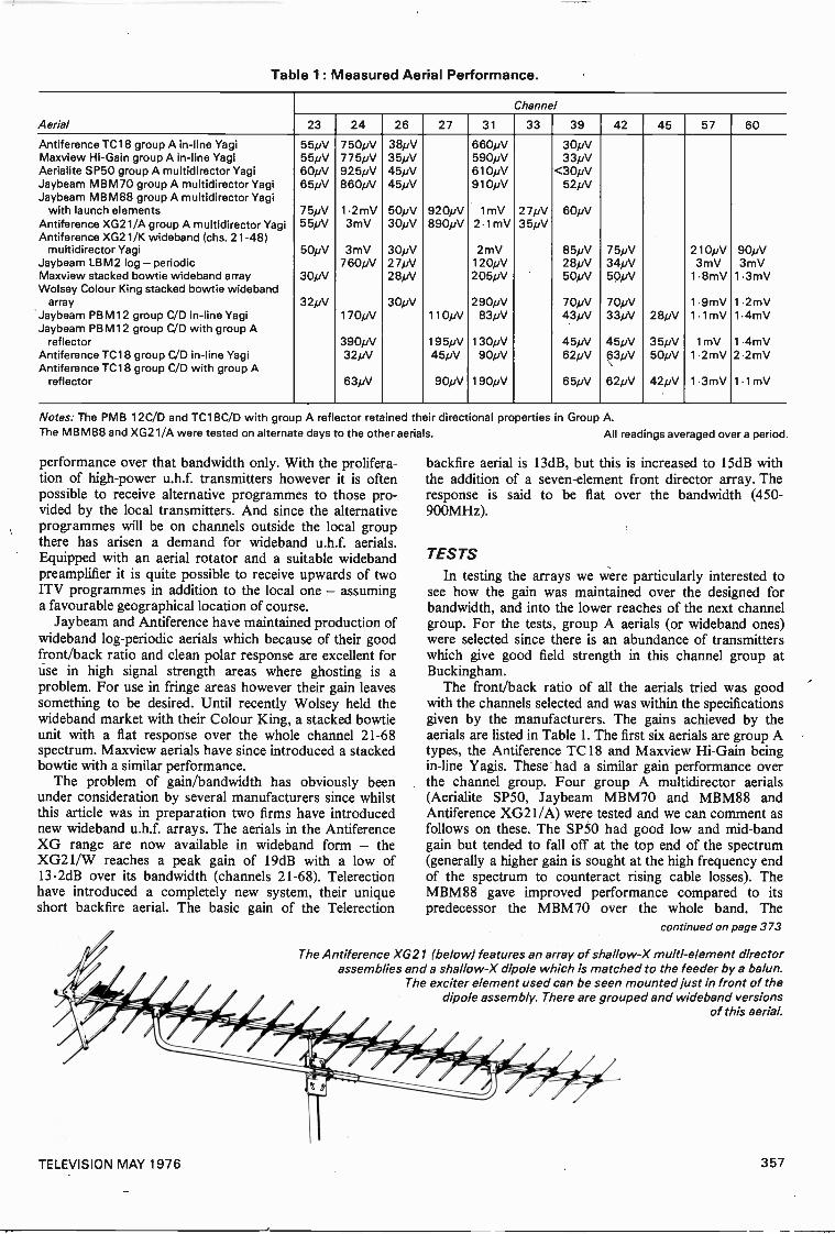
Table 1 : Measured Aerial Performance.
Aerial
Channel
23 24 26 27 31 33 39 42 45 57 60
Antiference TC18 group A in -line Yagi 55pV 750pV 38pV 660pV 30pVMaxview Hi -Gain group A in -line Yagi 55pV 775pV 35pV 590pV 33pVAerialite SP50 group A multidirector Yagi 60pV 925pV 45pV 610pV <30pVJaybeam MBM70 group A multidirector Yagi 65pV 860pV 45pV 910pV 52pVJaybeam MBM88 group A multidirector Yagi
with launch elements 75pV 1.2mV 50pV 920pV 1mV 27pV 60pVAntiference XG21/A group A multidirector Yagi 55pV 3mV 30pV 890pV 2- lmV 35pVAntiference XG21/K wideband (chs. 21-48)
multidirector Yagi 50pV 3mV 30pV 2mV 85pV 75pV 210pV 90pVJaybeam LBM2 log - periodic 760pV 27pV 120pV 28pV 34pV 3mV 3mVMaxview stacked bowtie wideband array 30pV 28pV 205pV 50pV 50pV 1.8mV 1 .3mVWolsey Colour King stacked bowtie wideband
array 32pV 30pV 290pV 70pV 70pV 1 .9mV 1.2mVJaybeam PBM12 group C/D in -line Yagi 170pV 110pV 83pV 43pV 33pV 28pV 11 mV 1.4mVJaybeam PB M12 group C/D with group A
reflector 390pV 195pV 130pV 45pV 45pV 35pV 1mV 1 .4mVAntiference TC18 group C/D in -line Yagi 32pV 45pV 90pV 62pV 63pV 50pV 1 .2mV 2.2mVAntiference TC18 group C/D with group A
reflector 63pV 90pV 190pV 65pV 62pV 42pV 1 -3mV 1-1mV
Notes: The PMB 12C/D and TC18C/D with group A reflector retained their directional properties in Group A.The MBM88 and XG21/A were tested on alternate days to the other aerials. All readings averaged over a period.
performance over that bandwidth only. With the prolifera-tion of high -power u.h.f. transmitters however it is oftenpossible to receive alternative programmes to those pro-vided by the local transmitters. And since the alternativeprogrammes will be on channels outside the local groupthere has arisen a demand for wideband u.h.f. aerials.Equipped with an aerial rotator and a suitable widebandpreamplifier it is quite possible to receive upwards of twoITV programmes in addition to the local one - assuminga favourable geographical location of course.
Jaybeam and Antiference have maintained production ofwideband log -periodic aerials which because of their goodfront/back ratio and clean polar response are excellent foruse in high signal strength areas where ghosting is aproblem. For use in fringe areas however their gain leavessomething to be desired. Until recently Wolsey held thewideband market with their Colour King, a stacked bowtieunit with a flat response over the whole channel 21-68spectrum. Maxview aerials have since introduced a stackedbowtie with a similar performance.
The problem of gain/bandwidth has obviously beenunder consideration by several manufacturers since whilstthis article was in preparation two firms have introducednew wideband u.h.f. arrays. The aerials in the AntiferenceXG range are now available in wideband form - theXG21/W reaches a peak gain of 19dB with a low of13.2dB over its bandwidth (channels 21-68). Telerectionhave introduced a completely new system, their uniqueshort backfire aerial. The basic gain of the Telerection
backfire aerial is 13dB, but this is increased to 15dB withthe addition of a seven -element front director array. Theresponse is said to be flat over the bandwidth (450-900MHz).
TESTSIn testing the arrays we were particularly interested to
see how the gain was maintained over the designed forbandwidth, and into the lower reaches of the next channelgroup. For the tests, group A aerials (or wideband ones)were selected since there is an abundance of transmitterswhich give good field strength in this channel group atBuckingham.
The front/back ratio of all the aerials tried was goodwith the channels selected and was within the specificationsgiven by the manufacturers. The gains achieved by theaerials are listed in Table 1. The first six aerials are group Atypes, the Antiference TC18 and Maxview Hi -Gain beingin -line Yagis. These had a similar gain performance overthe channel group. Four group A multidirector aerials(Aerialite SP50, Jaybeam MBM70 and MBM88 andAntiference XG21/A) were tested and we can comment asfollows on these. The SP50 had good low and mid -bandgain but tended to fall off at the top end of the spectrum(generally a higher gain is sought at the high frequency endof the spectrum to counteract rising cable losses). TheMBM88 gave improved performance compared to itspredecessor the MBM70 over the whole band. The
continued on page 373
The Antiference XG21 (below) features an array of shallow -X multi -element directorassemblies and a shallow -X dipole which is matched to the feeder by a balun.
The exciter element used can be seen mounted just in front of thedipole assembly. There are grouped and wideband versions
of this aerial.
TELEVISION MAY 1976 357
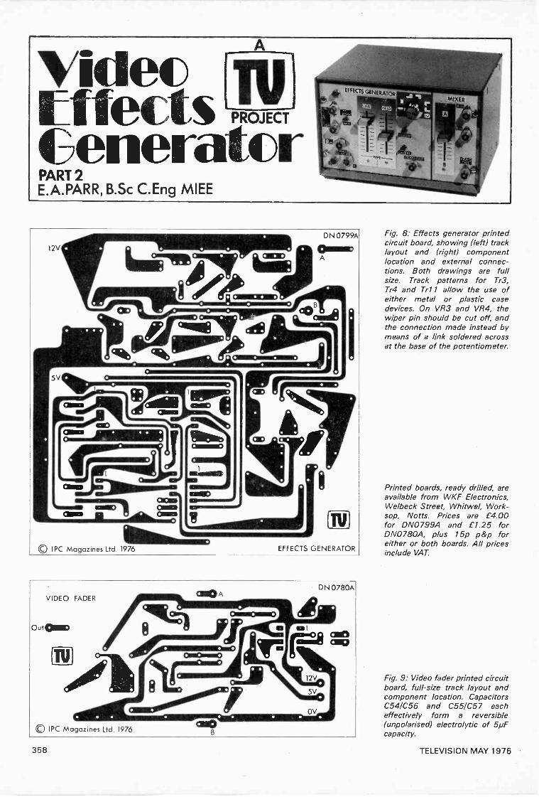
VideoEffects PROJECT
GeneratorPART 2E.A.PARR, B.Sc C.Eng MIEE
© IPC Magazines Ltd. 1976
VIDEO FADER
Out
Ph
© IPC Magazines Ltd. 1976
Tu)
EFFECTS GENERATOR
DN 0780A
gim.8 can
Fig. 8: Effects generator printedcircuit board, showing (left) tracklayout and (right) componentlocation and external connec-tions. Both drawings are fullsize. Track patterns for Tr3,Tr4 and Trl 1 allow the use ofeither metal or plastic casedevices. On VR3 and VR4, thewiper pin should be cut off, andthe connection made instead bymeans of a link soldered acrossat the base of the potentiometer.
Printed boards, ready drilled, areavailable from WKF Electronics,Welbeck Street, Whitwel, Work-sop, Notts. Prices are £4.00for DN0799A and £1.25 forDN0780A, plus 15p p&p foreither or both boards. All pricesinclude VAT.
Fig. 9: Video fader printed circuitboard, full-size track layout andcomponent location. CapacitorsC54/C56 and C55/C57 eacheffectively form a reversible(unpolarised) electrolytic of 5pFcapacity.
358 TELEVISION MAY 1976
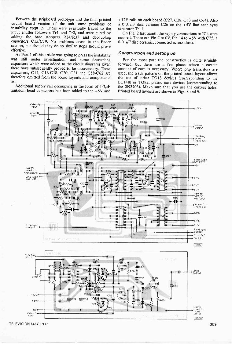
Between the stripboard prototype and the final printedcircuit board version of the unit some problems ofinstability crept in. These were eventually traced to theinput emitter followers Tr 1 and Tr2, and were cured byadding the base stoppers R34/R35 and decouplingcapacitors C15/C19. No problems arose in the Fadersection, but should they do so similar steps should proveeffective.
As Part 1 of this article was going to press the instabilitywas still under investigation, and some decouplingcapacitors which were added to the circuit diagrams giventhere have subsequently proved to be unnecessary. Thesecapacitors, C14, C16 -C18, C20, C21 and C58 -C62 aretherefore omitted from the board layouts and componentslist.
Additional supply rail decoupling in the form of 4.7µFtantalum bead capacitors has been added to the +5V and
Video AN,input
Video B.input
oCl
Earthbraid to
front panelLine wipe 4pot (VR1)
Line syncoutput
Video Ainput
Tr2
R6
"ria- R4 R8 R21 RYT/EriNTr5 IC15". D'2
ap34
1
\AApl b\,e
Tr
b'
C3
es71
R9
s
Fi
Tela
R35
D4 D5 R13 R2...
R7 seTr7 b
C 26Tr1C .7.
,.._ 4--I, . ; , 111,-...-.--e P30
Ir"-MAr-
12
R240--V\Arlo'
-"\AA,--fr It R25 N.1-R26
40" -AAA/-R28
Tr12 0^1\AA.0-4
Od\AArR27
,I7IR 2.,
V rails on each board (C27, C28, C63 and C64). Alsoa 0.0.01µF disc ceramic C26 on the +5V line near syncseparator Trll.
On Fig. 2 last month the supply connections to 1C4 wereomitted. These are Pin 7 to OV, Pin 14 to +5V with C25, a0.01/1F disc ceramic, connected across them.
6
Construction and setting up
For the most part the construction is quite straight-forward, but there are a few places where a certainamount of care is necessary. Where pnp transistors areused, the track pattern on the printed board layout allowsthe use of either TO18 devices (corresponding to theBC 148) or TO92, plastic case devices (corresponding tothe 2N3703). Make sure that you use the correct holes.Printed board layouts are shown in Figs. 8 and 9.
Tr6
tiD7 D9
R14
Try,,
Tr7
f ta
22
58 R15
C5
7 723
564
C 4
C27
U
IC31
4412V
Video'output
Blankingt drive(from S2)
"-"00V
Field wipespot (VR2)
-445V
.%
C25
S1/2
--*S1/3isS1/4
+5V to--0S1/1, S3.
VR1,VR2
-4 Al IOW "(from S3)
4
41C
il<g( 1C4
eitICoe.._ _
0--- S1/7
Field sync...._...output-0, Si wiper--. To S2
--1VR51
R54
R70/
R54,11
iC51R53
R71 1R69R52
-+ 12V if
C63- 5V it
OVA-Video B
input
Tr 54
R57
R61
D
R1511
6131
R66
-0.51/5
-+S1/6
1.:53
IN2991
Videooutput
Earth___,braid to-front
panel
1N3001
TELEVISION MAY 1976 359
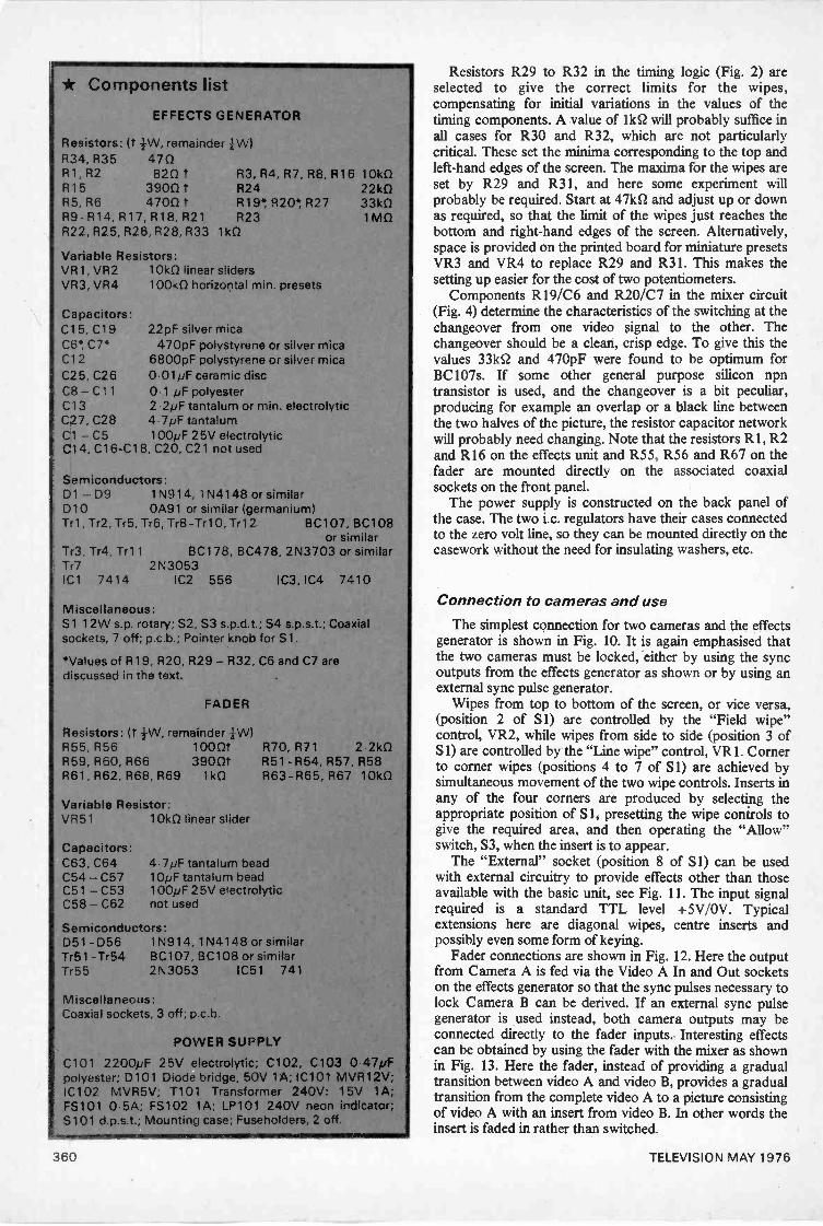
* Components listEFFECTS GENERATOR
Resistors: (t remainder +W)R34, R35 470R1, R2 820 tR15 3900 tR5, R6 4700 tR9 -R14, R17, R18, R21R22. R25, R26, R28, R33
R3, R4, R7, R8, R16 10k0R24 22k0R19* R20*, R27 33k0R23 1M0
1k0
Variable Resistors:VR1, VR2 10k0 linear slidersVR3, VR4 100k0 horizontal min. presets
Capacitors:C15, C19C6*, C7*C12C25, C26C8 -C11C13C27, C28
22pF silver mica470pF polystyrene or silver mica
6800pF polystyrene or silver mica0 01pF ceramic disc0 1 pF polyester2 2pF tantalum or min. electrolytic4 7pF tantalum
Cl - C5 100pF 25V electrolyticC14, C16 -C18, C20, C21 not used
Semiconductors:D1 - D9 1N914, 1N4148 or similarD10 0A91 or similar (germanium)Tr1, Tr2, Try, Tr6, Tr8-Tr10, Tr12 BC107, BC108
or similarTr3, Tr4, Tr11 BC178, BC478, 2N3703 or similarTr7 2N3053IC1 7414 IC2 556 IC3, IC4 7410
Miscellaneous:S1 12W s.p. rotary; S2, S3 s.p.d.t.; S4 s.p.s.t.; Coaxialsockets, 7 off; p.c.b.; Pointer knob for S1.
*Values of R19, R20, R29 - R32, C6 and C7 arediscussed in the text.
FADER
Resistors: (r 4W, remainder +W)R55, R56 1000tR59, R60, R66 3900tR61 R62, R68, R69 1k0
Variable Resistor:VR51 10k0 linear slider
Capacitors:C63, C64C54 - C57C51 - C53C58 - C62
570, R71 2 2k0R51 -R54, R57, R58R63 -R65, R67 10k0
4-7pF tantalum bead10pF tantalum bead100pF 25V electrolyticnot used
Semiconductors:D51 -D56 1N914, 1N4148 or similarTr51 - Tr54 BC107, BC108 or similarTr55 2N3053 IC51 741
Miscellaneous:Coaxial sockets, 3 off; p.c.b.
POWER SUPPLY
C101 2200pF 25V electrolytic; C102, C103 0-47pFpolyester; D101 Diode bridge, 50V 1A: IC101 MVR12V;IC102 MVR5V; T101 Transformer 240V: 15V 1A;FS101 0-5A; FS102 1A; LP101 240V neon indicator;S101 d.p.s.t.; Mounting case; Fuseholders, 2 off.
mesamLm1WONOW14,1.11111811WININ
Resistors R29 to R32 in the timing logic (Fig. 2) areselected to give the correct limits for the wipes,compensating for initial variations in the values of thetiming components. A value of lkS2 will probably suffice inall cases for R30 and R32, which are not particularlycritical. These set the minima corresponding to the top andleft-hand edges of the screen. The maxima for the wipes areset by R29 and R31, and here some experiment willprobably be required. Start at 47kS2 and adjust up or downas required, so that the limit of the wipes just reaches thebottom and right-hand edges of the screen. Alternatively,space is provided on the printed board for miniature presetsVR3 and VR4 to replace R29 and R31. This makes thesetting up easier for the cost of two potentiometers.
Components R19/C6 and R20/C7 in the mixer circuit(Fig. 4) determine the characteristics of the switching at thechangeover from one video signal to the other. Thechangeover should be a clean, crisp edge. To give this thevalues 33kS2 and 470pF were found to be optimum forBC107s. If some other general purpose silicon npntransistor is used, and the changeover is a bit peculiar,producing for example an overlap or a black line betweenthe two halves of the picture, the resistor capacitor networkwill probably need changing. Note that the resistors R1, R2and R16 on the effects unit and R55, R56 and R67 on thefader are mounted directly on the associated coaxialsockets on the front panel.
The power supply is constructed on the back panel ofthe case. The two i.c. regulators have their cases connectedto the zero volt line, so they can be mounted directly on thecasework without the need for insulating washers, etc.
Connection to cameras and use
The simplest connection for two cameras and the effectsgenerator is shown in Fig. 10. It is again emphasised thatthe two cameras must be locked, either by using the syncoutputs from the effects generator as shown or by using anexternal sync pulse generator.
Wipes from top to bottom of the screen, or vice versa,(position 2 of S1) are controlled by the "Field wipe"control, VR2, while wipes from side to side (position 3 ofSi) are controlled by the "Line wipe" control, VR1. Cornerto corner wipes (positions 4 to 7 of S1) are achieved bysimultaneous movement of the two wipe controls. Inserts inany of the four corners are produced by selecting theappropriate position of S 1, presetting the wipe controls togive the required area, and then operating the "Allow"switch, S3, when the insert is to appear.
The "External" socket (position 8 of Si) can be usedwith external circuitry to provide effects other than thoseavailable with the basic unit, see Fig. 11. The input signalrequired is a standard TTL level +5V/OV. Typicalextensions here are diagonal wipes, centre inserts andpossibly even some form of keying.
Fader connections are shown in Fig. 12. Here the outputfrom Camera A is fed via the Video A In and Out socketson the effects generator so that the sync pulses necessary tolock Camera B can be derived. If an external sync pulsegenerator is used instead, both camera outputs may beconnected directly to the fader inputs. Interesting effectscan be obtained by using the fader with the mixer as shownin Fig. 13. Here the fader, instead of providing a gradualtransition between video A and video B, provides a gradualtransition from the complete video A to a picture consistingof video A with an insert from video B. In other words theinsert is faded in rather than switched.
TELEVISION MAY 1976
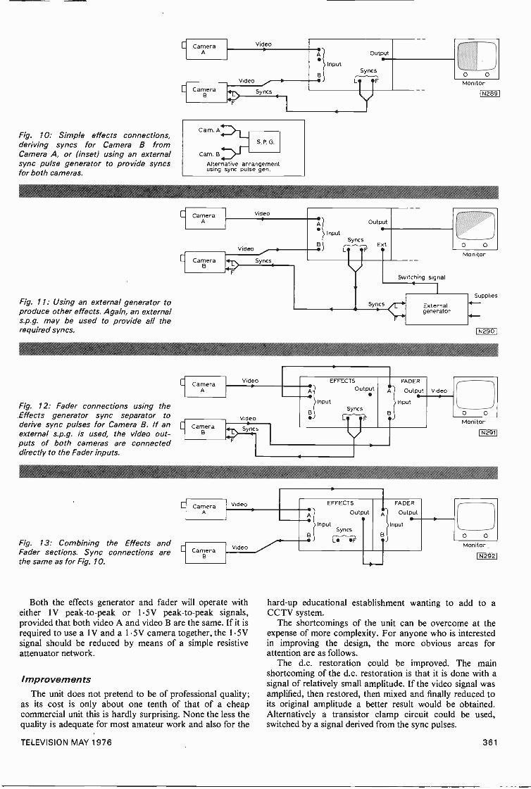
Fig. 10: Simple effects connections,deriving syncs for Camera B fromCamera A, or (inset) using an externalsync pulse generator to provide syncsfor both cameras.
Fig. 11: Using an external generator toproduce other effects. Again, an externals.p.g. may be used to provide all therequired syncs.
Fig. 12: Fader connections using theEffects generator sync separator toderive sync pulses for Camera B. If anexternal s.p.g. is used, the video out-puts of both cameras are connecteddirectly to the Fader inputs.
Fig. 13: Combining the Effects andFader sections. Sync connections arethe same as for Fig. 10.
VideoC CameraA OutputA
InputSyncs
B
C CameraB
Video
Syncs
Cam. B
Alternative arrangementusing sync pulse gen.
CameraA
Video
CameraB
CameraA
CameraB
CameraA
Video
Sync so
Video
Video
Syncs
Video
A
B
InputSyncs
L
Output
Ext
O OMonitor
I. N289
Switching signal
B
EFFECTS
Output
InputSyncs
1
F
O O
Monitor
Externalgenerator
FADER
Output
Input
Video
Supplies
1 N2901
CameraB
Video
Both the effects generator and fader will operate witheither IV peak -to -peak or 1-5V peak -to -peak signals,provided that both video A and video B are the same. If it isrequired to use a 1V and a 1.5V camera together, the 1.5Vsignal should be reduced by means of a simple resistiveattenuator network.
ImprovementsThe unit does not pretend to be of professional quality;
as its cost is only about one tenth of that of a cheapcommercial unit this is hardly surprising. None the less thequality is adequate for most amateur work and also for the
A
B
EFFECTS
Output
InputSyncs
L F
FADER
Output
Input
Monitor
N291I
Monitor
1142921
hard -up educational establishment wanting to add to aCCTV system.
The shortcomings of the unit can be overcome at theexpense of more complexity. For anyone who is interestedin improving the design, the more obvious areas forattention are as follows.
The d.c. restoration could be improved. The mainshortcoming of the d.c. restoration is that it is done with asignal of relatively small amplitude. If the video signal wasamplified, then restored, then mixed and finally reduced toits original amplitude a better result would be obtained.Alternatively a transistor clamp circuit could be used,switched by a signal derived from the sync pulses.
TELEVISION MAY 1976 361
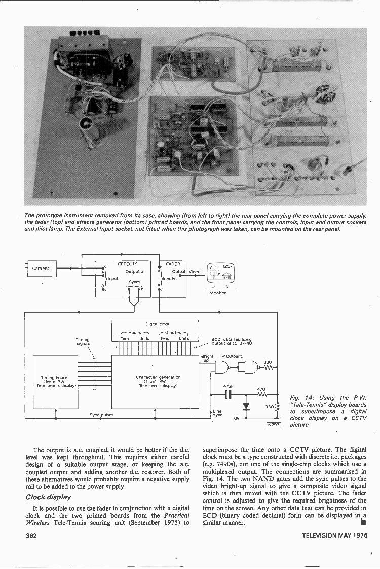
f tooktt,
e
' f
The prototype instrument removed from its case, showing (from left to right) the rear panel carrying the complete power supply,the fader (top) and effects generator (bottom) printed boards, and the front panel carrying the controls, input and output socketsand pilot lamp. The External Input socket, not fitted when this photograph was taken, can be mounted on the rear panel.
CameraEFFECTS
A
Input
Outputo
Syncs
FL
Timingsignals
Timing board(from P.W.
Tele-tennis display)
FADER
A Output
Inputs
Video
O O
Monitor
Digital clock
,-Hours -1M inutesTens Units Tens Units
Character generation( from P.W.
Tele-tennis display)
Sync pulses
BCD data replacingoutput of IC 37-40
Bright 7400(part)up
47uF
The output is a.c. coupled, it would be better if the d.c.level was kept throughout. This requires either carefuldesign of a suitable output stage, or keeping the a.c.coupled output and adding another d.c. restorer. Both ofthese alternatives would probably require a negative supplyrail to be added to the power supply.
Clock displayIt is possible to use the fader in conjunction with a digital
clock and the two printed boards from the PracticalWireless Tele-Tennis scoring unit (September 1975) to
Linesync
470
0v -.
330
1N2931
Fig. 14: Using the P.W.'Tele-Tennis" display boardsto superimpose a digitalclock display on a CCTVpicture.
superimpose the time onto a CCTV picture. The digitalclock must be a type constructed with discrete i.c. packages(e.g. 7490s), not one of the single -chip clocks which use amultiplexed output. The connections are summarised inFig. 14. The two NAND gates add the sync pulses to thevideo bright -up signal to give a composite video signalwhich is then mixed with the CCTV picture. The fadercontrol is adjusted to give the required brightness of thetime on the screen. Any other data that can be provided inBCD (binary coded decimal) form can be displayed in asimilar manner.
362 TELEVISION MAY 1976
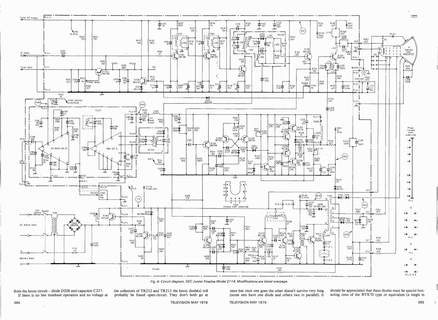
Tuner HT supply 1777
IF input PL1-4
Tuner AGCa
1PL1-3
pL3_3
0195100
I
25VZ
CI98PL2-7 1220
1i
IPL1-1
LS8 ji
C019590
R19910
PL -211?_73
C102560p
R14210
C193200p
R194lk C196
001
C470I44-
16 V,
\20Vto R11.4
R10415k
R101 C101
2k2 .05
P101
5k
From junctionC401/R402
C1970.1
PL3-2
F51 SW400
210r4A 01401
AC mains input
Battery input
184
200p
R10218k
Preset delay
R1032k7
RI93390
186
,.100
0194
005/7
FS220
CI89
TrI04BC158
PC47I
C107.1. C150, Tr10501
16VTI
BC148
1.199i ...0190°,5
56p."
C1920.1
PL 8-1
PL 2-5
7
CI88...560
14
0
13
TBA 1200
4,
Volume
12
PL 3-8
TP3 TP2R109560
Ik8R120180k
RI15
D101,ZE1.5.d
RI30100
R121220
CII30.1
mr-C103 R107 01 820
510647
FLio,C104
L_
L202
C108711. /2C2140511VI6V .from
C402
PL 3-63
PL3-5
0191 1C185 '05'022
R19610k
C180,
I.051.61-3 7 PL3-4
y
R40610
4013300
P7276
P30310k
log
Tr401AD149
from the boost circuit - diode D208 and capacitor C237.If there is no line timebase operation and no voltage at
PL 2-3
@--q,
PL2-1
C
PL 2-8
C
PL2-4
IPL 2-2
C136300 L116
R1455k6
01040090
C105105
T101 -11104
,_J5rrtnTrI01BFI96
R11310k
R112
100
ClOi330
OT
R1161k
1102
R11812k
1103
C110,i
:
:IR117
0II
; LION: 56i
1._ _ 6 -X-I4Tr 102BF 197
C109 05
RIO3k3
TR114
C1153P-11
L105
C116
T
R12382
R119C112
1k.OT
I 1k2.05
TrI03BFI97
R124 iC122470
nt056
4106
11035
100p.
1 L108
D1030A90 _L107
R122120
L 2
-0123.005
1C146220
725V
C1I4022
RI274k7
R1282k7
Tr106
5129 BC148100
TP4(3--*
R133
5132220
Presetvideo.
0102IN4148
nl
L115
1104
PC401
20V R14468k
C137
illy toR142 R130/1202
C40322016V
R401100
D401,BZY88 C6V241
R40256
Tr402BC338
540368
SetII V
PC460
01
C1351006
C20622016V
02010091
R20 R2033k3 39k
C201
5201 92045k6 680k
Tr202BC154
Tr 201BC158
R210 C20710k 047
1:20R206
005
4k7
I
R216270
Vert.hold
R21933k
C208 02020.47 19A128
R217330
P20247k
R22010k
Vert.amp.
Tr203BC154
D204130128
R222R2I8 330k470k R221
10k
0203..A60128
P203220k
R22327k
R2242k7
rri-o2121
R225.0015390 ,
Tr205BC 208
Tr204BC208
Tr206BC154
R226
T0033
C21510
16V
Tr207BC116
R22910
V D205.mBA429
R228330
330
P1021k
5134100
25.6VfromC 237
RI351
L113
4k7
L112
C124
200p
R131680
P14-1,11
TH201
IL 205C217
01C2160.68 P14-2
1110
100171fromC234
R2502k2R138
5303SC6 2k2
I-C12813.1 R25
Tr10733k
BF178
C125
560p
R136180
R137 IC1264k7
T2206
R13910k
C218
1.068
Iry
R231
C2I4470I6V
R23\2.120
Tr208B3324
P204 Vert. lin.470k
C211'047
R22722k
R233100k
4 k 7
1.213C0234
7-22 7100V
R404390
P401 C402220 =1000
I6V
R405390
R20547k
C238005
Tr 209BC148
R208470
3
2
0
8 7 6T202
Viewed from underside
C204058
R135
R24910
D210BY184
R252220k
SC4
PL 5-2
->
Brightniess11--> <
-P15.11
P437°kP1302Contras 500
PL 9-1
PL 5-4
PL5-3
PL7-1
C30122010V
SG44.
1 I
1 I
I 1
14"
, ToshibaI I '
type1 1 M6529FZP
R3132 M2
e.,\AA.041
.1060018
350V
SC5
PL 6-1 rIN PL 6-2
--
L201L
C228-022
C227015C22
10
16V R23715
16
R2405k6
Tr 211BC148
R2341 k5
R23947
R242
25.6Vto R134
/C237220 D208TI6V BYX55 -350/ DOI
120210
C23I220
16VZ
C2321
0417R243
150 270201
C22
.022
Fig. 4: Circuit diagram, GEC Junior Fineline Model 2114. Modifications are listed overpage.
the collectors of TR212 and TR213 the boost diode(s) willprobably be found open -circuit. They don't both go at
Tr212BC 337
HOriZ.:1in.:
Tr 213BDI60
1
12
13
1203
0212 TV18
0414_44
3D209 R244BY184 isk
C 233
1.2-2PL 6-4
once but once one goes the other doesn't survive very long(some sets have one diode and others two in parallel). It
PL6-3
R2452M 2
D211BA145
100k SC3 1 8k2R247 5304
R241333k
crinI
02*4 /
Plugsviewedfrom
underside
1111
20
3111
5*
80
PL 3
0
80 1
7* 2
60 3
50 116
PL 2
0
211 1PL4
30 *2
should be appreciated that these diodes must be special fast -acting ones of the BYX70 type or equivalent (a single in
364 TELEVISION MAY 1976 TELEVISION MAY 1976 365
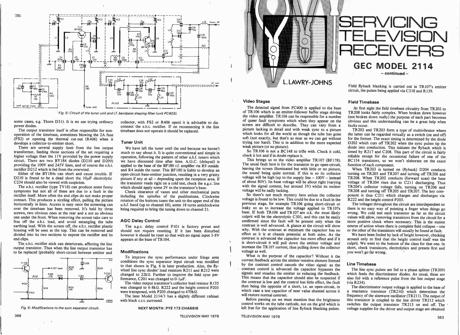
113841
rr
VCI
135pT1351, C3
T270p.-
RI10k
UHF aerial input SKI
1
I T2
JlTrl 1
BF180
VC2
L2 L4
/74 680R4
C4200p
R3390
R21M2
R9180
Tuner AGC
L_
T3
LS
,4n
C 23
30p
iVC4
C2822 p
C24 C2722p 120p 92p
PC 403
L22
L6
-r 1
L9
LB
CI4 I
331 LI0 Tuner HT
.7.,
iCI9C915P10
LC2968p
ly C30150p
Fig. 5: Circuit of the tuner uni and if bandpass shaping filter (unit PC403).
some cases, e.g. Thorn D31). It is no use trying ordinarypower diodes.
The output transistor itself is often responsible for non -operation of the timebase, sometimes blowing the 2A fuse(FS2) or opening the thermal cut-out (R406) when itdevelops a collector -to -emitter short.
There are several supply lines from the line outputtransformer, feeding those sections of the set requiring ahigher voltage than the 11V provided by the power supplycircuit. There are two BY184 diodes (D210 and D209)providing the 100V and 245V lines, and of course the e.h.t.rectifier D212 which is fed from the overwind.
Either of the BY184s can short and cause trouble. IfD210 is found to be a dead short the 10µF electrolyticC234 should also be viewed with suspicion.
The e.h.t. rectifier (type TV18) can produce some funnysymptoms but not all of these are due to a fault in therectifier itself. More often the end clips do not make propercontact. This produces a sizzling effect, pulling the picturehorizontally in lines. Access is easy once the screening canover the timebase has been removed. It's held by threescrews, two obvious ones at the rear and a not so obviousone under the front. When removing the screen take care tofree off the e.h.t. lead, and avoid entangling the tubeearthing lead. With the screen off, the e.h.t. rectifier plastichousing will be seen at the top. This can be removed anddivided into its two sections to expose the rectifier and itsend clips.
The e.h.t. rectifier stick can deteriorate, affecting the lineoutput transistor. Thus when the line output transistor hasto be replaced (probably short-circuit between emitter and
Tr107 base R203
R230470 0201
113721
Fig. 6: Modifications to the sync separator circuit.
II ""00151
3k3
T0.1)I
C20
IF out- law
collector, with FS2 or R406 open) it is advisable to dis-connect the e.h.t. rectifier. If on reconnecting it the linetimebase does not operate it should be replaced.
Tuner UnitWe have left the tuner until the end because we haven't
much to say about it. It is quite conventional and simple inoperation, following the pattern of other u.h.f. tuners whichwe have discussed time after time. A.G.C. (delayed) isapplied to the base of the BF180 r.f. amplifier via R9 outsideand R4 inside the tuner. This BF180 is liable to develop anopen -circuit base -emitter junction, resulting in a very grainypicture if any at all - depending upon the reception area. Ifthe transistor reads right on a cold test, check the a.g.c. linewhich should apply some 2V to the transistor's base.
Check clearance of vanes and other mechanical partsincluding the spindles of the pushbuttons. Clockwiserotation of the buttons tunes the unit to the upper end of theu.h.f. band (up to channel 68), some 18 turns anticlockwisebeing required to bring the tuning down to channel 21.
AGC Delay ControlThe a.g.c. delay control P101is factory preset and
should not require resetting. If it has been disturbedhowever it should be reset so that with no signal input 3.8Vappears at the base of TR104.
ModificationsTo improve the sync performance under fringe area
conditions the sync separator input circuit was modifiedto that shown in Fig. 6 in later production. Also, the fly-wheel line sync diodes' load resistors R211 and R212 werechanged to 221(52. Further to improve the field sync per-formance, C201 was changed to 0.1µF.
The video output transistor's collector load resistor R135was changed to 6.8k52. R222 and the height control P203were transposed, with P203 changed to 470k52.
The later Model 2114/1 has a slightly different cabinetwith black c.r.t. surround.
NEXT MONTH: PYE 173 CHASSIS
SERVICINGTELEVISIONRECEIVERS
L. LAWRY-JOHNS
Video StagesThe detected signal from PC400 is applied to the base
of TR106 which is an emitter -follower buffer stage drivingthe video amplifier. TR106 can be responsible for a numberof queer fault symptoms which when they appear on thescreen are difficult to describe. They can vary from apicture lacking in detail and with weak sync to a picturewhich looks for all the world as though the tube has gonesoft (not exactly, but that's as near as we can get withouttrying too hard). This is in addition to the more expectedweak picture (or no picture).
So TR 106 is not a BC 148 to trifle with. Check it cold,check it hot and if in doubt replace it.
This brings us to the video amplifier TR107 (BF178).The usual fault here is for the transistor to go open -circuit,leaving the screen illuminated but with little or no picture,the sound being quite normal. If this is so its collectorvoltage will be high (up to the supply line - 100V - insteadof about 80V). Its base voltage will be about right (varyingwith the signal content, but around 3V) whilst its emittervoltage will be sadly lacking.
So there's not much mystery here unless the collectorvoltage is found to be low. This could be due to a fault in theprevious stage, for example TR106 going short-circuit orleaky so as to increase the voltage applied to TR107sbase. If both TR106 and TR107 are o.k. the most likelyculprit will be the electrolytic C301, and this can be easilyconfirmed since the fault will be present only when thecontrast is well advanced. A glance at the circuit will showwhy. With the contrast at minimum the capacitor has noeffect as it is at chassis potential at both sides. As thecontrast is advanced the capacitor has more effect and if itis short-circuit it will pull down the emitter voltage andincrease the TR 107 current, thus pulling down the collectorvoltage as well.
What is the purpose of the capacitor? Without it thecurrent feedback across the emitter resistive element formedby the contrast control cancels the video signal: as thecontrast control is advanced the capacitor bypasses thesignals and steadies the emitter so reducing the feedback.This means that the capacitor should also be suspected ifthe contrast is low and the control has little effect, the faultthen being the opposite of a short, i.e. an open -circuit, inwhich case a test capacitor of near value shunted across itwill restore normal contrast.
Before passing on we must mention that the brightnesscontrol works on the tube cathode, not on the grid which isleft free for the application of line flyback blanking pulses.
GEC MODEL 2114- continued -
Field flyback blanking is carried out in TR 107's emittercircuit, the pulses being applied via C218 and RI39.
Field TimebaseAt first sight the field timebase circuitry from TR202 to
TR208 looks fairly complex. When broken down however(not broken down really) the purpose of each part becomesobvious and this understanding can be a great help whenfaults occur.
TR202 and TR203 form a type of multivibrator wherethe latter can be regarded virtually as a switch (on and off)for the former. The exact timing is determined by the diodeD202 which cuts off TR202 when the sync pulses tip thediode into conduction. This initiates the flyback which istimed by R217 and C208. This part of the circuit is fairlyreliable except for the occasional failure of one of theBC 154 transistors, so we won't elaborate on the exactfunction of each component.
When TR203 is turned on (flyback) D204 conductsturning on TR205 and TR207 and turning off TR206 andTR208. When TR202 conducts (forward scan) the basevoltage of TR204 rises due to C211 discharging. ThusTR204's collector voltage falls, turning on TR206 andTR208 and turning off TR205 and TR207. The key com-ponent is thus C211 which charges and discharges viaR222 and the height control P203.
The voltages throughout the circuit are interdependent sothere is no easy way of pointing a finger when things gowrong. We cold test each transistor as far as the circuitvalues will allow, removing transistors from the circuit for amore positive check where necessary. This is the easiestcourse of action where there is complete field collapse - oneor the other of the transistors will usually be found at fault.
We have been fooled by lack of height however, checkingaround only to find that the height control itself was theculprit. We went to the bottom of the class for that one. Inshort, check transistors, electrolytics and presets first andyou won't go far wrong.
Line TimebaseThe line sync pulses are fed to a phase splitter (TR209)
which feeds the discriminator diodes. As usual, these arealso fed with a reference pulse from the line output stage(via R234).
The discriminator output voltage is applied to the base ofa reactance transistor (TR210) which determines thefrequency of the sinewave oscillator (TR211). The output ofthis transistor is coupled to the line driver TR212 whichswitches the output transistor TR213 on and off. Thevoltage supplies for the driver and output stage are obtained
366 TELEVISION MAY 1976 TELEVISION MAY 1976 363
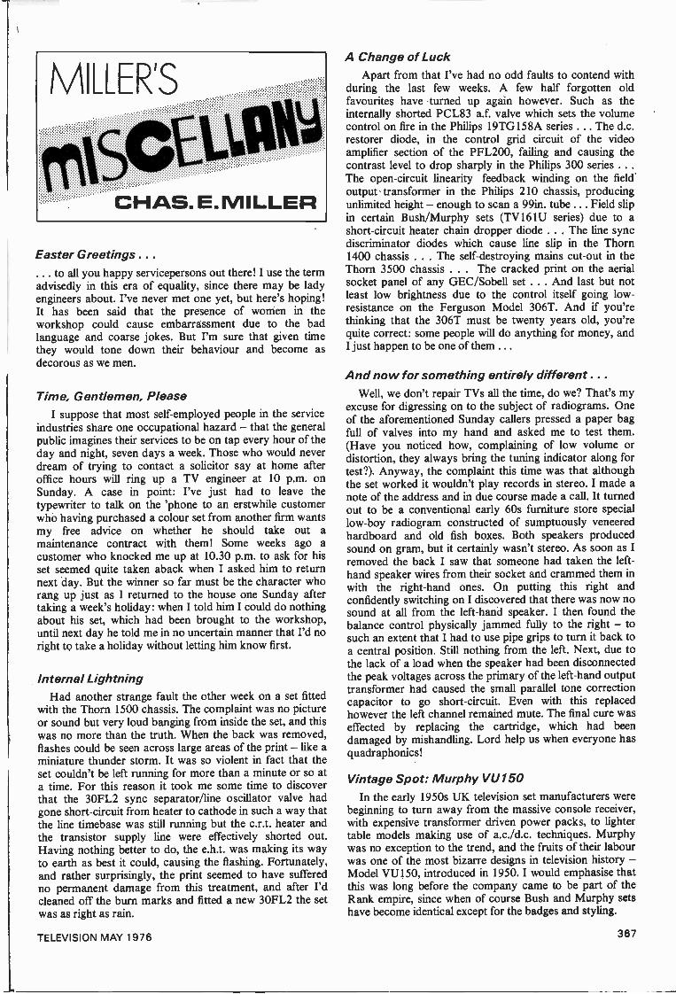
Easter Greetings . . .
. to all you happy servicepersons out there! I use the termadvisedly in this era of equality, since there may be ladyengineers about. I've never met one yet, but here's hoping!It has been said that the presence of women in theworkshop could cause embarrassment due to the badlanguage and coarse jokes. But I'm sure that given timethey would tone down their behaviour and become asdecorous as we men.
Time, Gentlemen, PleaseI suppose that most self-employed people in the service
industries share one occupational hazard - that the generalpublic imagines their services to be on tap every hour of theday and night, seven days a week. Those who would neverdream of trying to contact a solicitor say at home afteroffice hours will ring up a TV engineer at 10 p.m. onSunday. A case in point: I've just had to leave thetypewriter to talk on the 'phone to an erstwhile customerwho having purchased a colour set from another firm wantsmy free advice on whether he should take out amaintenance contract with them! Some weeks ago acustomer who knocked me up at 10.30 p.m. to ask for hisset seemed quite taken aback when I asked him to returnnext day. But the winner so far must be the character whorang up just as I returned to the house one Sunday aftertaking a week's holiday: when I told him I could do nothingabout his set, which had been brought to the workshop,until next day he told me in no uncertain manner that I'd noright to take a holiday without letting him know first.
Internal LightningHad another strange fault the other week on a set fitted
with the Thorn 1500 chassis. The complaint was no pictureor sound but very loud banging from inside the set, and thiswas no more than the truth. When the back was removed,flashes could be seen across large areas of the print - like aminiature thunder storm. It was so violent in fact that theset couldn't be left running for more than a minute or so ata time. For this reason it took me some time to discoverthat the 30FL2 sync separator/line oscillator valve hadgone short-circuit from heater to cathode in such a way thatthe line timebase was still running but the c.r.t. heater andthe transistor supply line were effectively shorted out.Having nothing better to do, the e.h.t. was making its wayto earth as best it could, causing the flashing. Fortunately,and rather surprisingly, the print seemed to have sufferedno permanent damage from this treatment, and after I'dcleaned off the burn marks and fitted a new 30FL2 the setwas as right as rain.
A Change of LuckApart from that I've had no odd faults to contend with
during the last few weeks. A few half forgotten oldfavourites have turned up again however. Such as theinternally shorted PCL83 a.f. valve which sets the volumecontrol on fire in the Philips 19TG158A series . .. The d.c.restorer diode, in the control grid circuit of the videoamplifier section of the PFL200, failing and causing thecontrast level to drop sharply in the Philips 300 series . . .
The open -circuit linearity feedback winding on the fieldoutput transformer in the Philips 210 chassis, producingunlimited height - enough to scan a 99in. tube ... Field slipin certain Bush/Murphy sets (TV161U series) due to ashort-circuit heater chain dropper diode . . . The line syncdiscriminator diodes which cause line slip in the Thorn1400 chassis . . . The self -destroying mains cut-out in theThorn 3500 chassis . . . The cracked print on the aerialsocket panel of any GEC/Sobell set . . . And last but notleast low brightness due to the control itself going low -resistance on the Ferguson Model 306T. And if you'rethinking that the 306T must be twenty years old, you'requite correct: some people will do anything for money, andI just happen to be one of them ...
And now for something entirely different . . .
Well, we don't repair TVs all the time, do we? That's myexcuse for digressing on to the subject of radiograms. Oneof the aforementioned Sunday callers pressed a paper bagfull of valves into my hand and asked me to test them.(Have you noticed how, complaining of low volume ordistortion, they always bring the tuning indicator along fortest?). Anyway, the complaint this time was that althoughthe set worked it wouldn't play records in stereo. I made anote of the address and in due course made a call. It turnedout to be a conventional early 60s furniture store speciallow -boy radiogram constructed of sumptuously veneeredhardboard and old fish boxes. Both speakers producedsound on gram, but it certainly wasn't stereo. As soon as Iremoved the back I saw that someone had taken the left-hand speaker wires from their socket and crammed them inwith the right-hand ones. On putting this right andconfidently switching on I discovered that there was now nosound at all from the left-hand speaker. I then found thebalance control physically jammed fully to the right - tosuch an extent that I had to use pipe grips to turn it back toa central position. Still nothing from the left. Next, due tothe lack of a load when the speaker had been disconnectedthe peak voltages across the primary of the left-hand outputtransformer had caused the small parallel tone correctioncapacitor to go short-circuit. Even with this replacedhowever the left channel remained mute. The final cure waseffected by replacing the cartridge, which had beendamaged by mishandling. Lord help us when everyone hasquadraphonics!
Vintage Spot: Murphy VU150In the early 1950s UK television set manufacturers were
beginning to turn away from the massive console receiver,with expensive transformer driven power packs, to lightertable models making use of a.c./d.c. techniques. Murphywas no exception to the trend, and the fruits of their labourwas one of the most bizarre designs in television history -Model VU150, introduced in 1950. I would emphasise thatthis was long before the company came to be part of theRank empire, since when of course Bush and Murphy setshave become identical except for the badges and styling.
TELEVISION MAY 1976 367
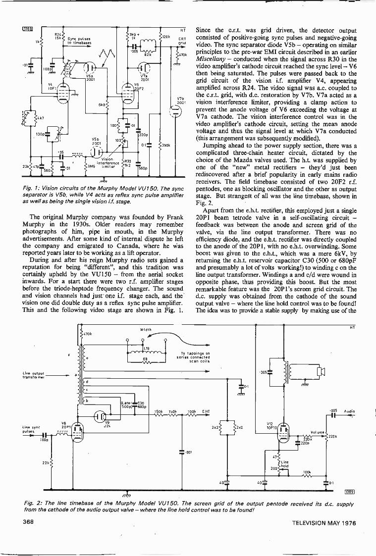
Sync pulsesto timebases
01
22k 47p11560
20D1
Vi ioninter erence
9 limiterR30
2T6Op
20k
390k
HT
CRTgrid
470k
V7b20D1
,,TFig. 1: Vision circuits of the Murphy Model VU150. The syncseparator is V5b, while V4 acts as reflex sync pulse amplifieras well as being the single vision if. stage.
The original Murphy company was founded by FrankMurphy in the 1930s. Older readers may rememberphotographs of him, pipe in mouth, in the Murphyadvertisements. After some kind of internal dispute he leftthe company and emigrated to Canada, where he wasreported years later to be working as a lift operator.
During and after his reign Murphy radio sets gained areputation for being "different", and this tradition wascertainly upheld by the VU150 - from the aerial socketinwards. For a start there were two r.f. amplifier stagesbefore the triode-heptode frequency changer. The soundand vision channels had just one i.f. stage each, and thevision one did double duty as a reflex sync pulse amplifier.This and the following video stage are shown in Fig. I.
Line outputtransformer
Line syncpulses
V820P1
100p
22k
Since the c.r.t. was grid driven, the detector outputconsisted of positive -going sync pulses and negative -goingvideo. The sync separator diode V5b - operating on similarprinciples to the pre-war EMI circuit described in an earlierMiscellany - conducted when the signal across R30 in thevideo amplifier's cathode circuit reached the sync level - V6then being saturated. The pulses were passed back to thegrid circuit of the vision i.f. amplifier V4, appearingamplified across R24. The video signal was a.c. coupled tothe c.r.t. grid, with d.c. restoration by V7b. V7a acted as avision interference limiter, providing a clamp action toprevent the anode voltage of V6 exceeding the voltage atV7a cathode. The vision interference control was in thevideo amplifier's cathode circuit, setting the mean anodevoltage and thus the signal level at which V7a conducted(this arrangement was subsequently modified).
Jumping ahead to the power supply section, there was acomplicated three -chain heater circuit, dictated by thechoice of the Mazda valves used. The h.t. was supplied byone of the "new" metal rectifiers - they'd just beenrediscovered after a brief popularity in early mains radioreceivers. The field timebase consisted of two 20F2 r.f.pentodes, one as blocking oscillator and the other as outputstage. But strangest of all was the line timebase, shown inFig. 2.
Apart from the e.h.t. rectifier, this employed just a single20P 1 beam tetrode valve in a self -oscillating circuit -feedback was between the anode and screen grid of thevalve, via the line output transformer. There was noefficiency diode, and the e.h.t. rectifier was directly coupledto the anode of the 20P1, with no e.h.t. overwinding. Someboost was given to the e.h.t., which was a mere 6kV, byreturning the e.h.t. reservoir capacitor C30 (500 or 680pFand presumably a lot of volts working!) to winding c on theline output transformer. Windings a and c/d were wound inopposite phase, thus providing this boost. But the mostremarkable feature was the 20P l's screen grid circuit. Thed.c. supply was obtained from the cathode of the soundoutput valve - where the line hold control was to be found!The idea was to provide a stable supply by making use of the
Width470k
L19
68
To tappings onseries connected
scan coils
V9U24
(LaterIC30500p) 680p
/477
Fig. 2: The line timebase of the Murphy Model VU150. The screen grid of the output pentode received its d.c. supplyfrom the cathode of the audio output valve - where the line hold control was to be found!
150k 150k 100k EHT
2k2 2k2
01
005
V1210P13
401 CO'?
47
200
I
Linehold
005
HT
Audio
Volume
220k220k
T220P
100k
0.1
113691
368 TELEVISION MAY 1976
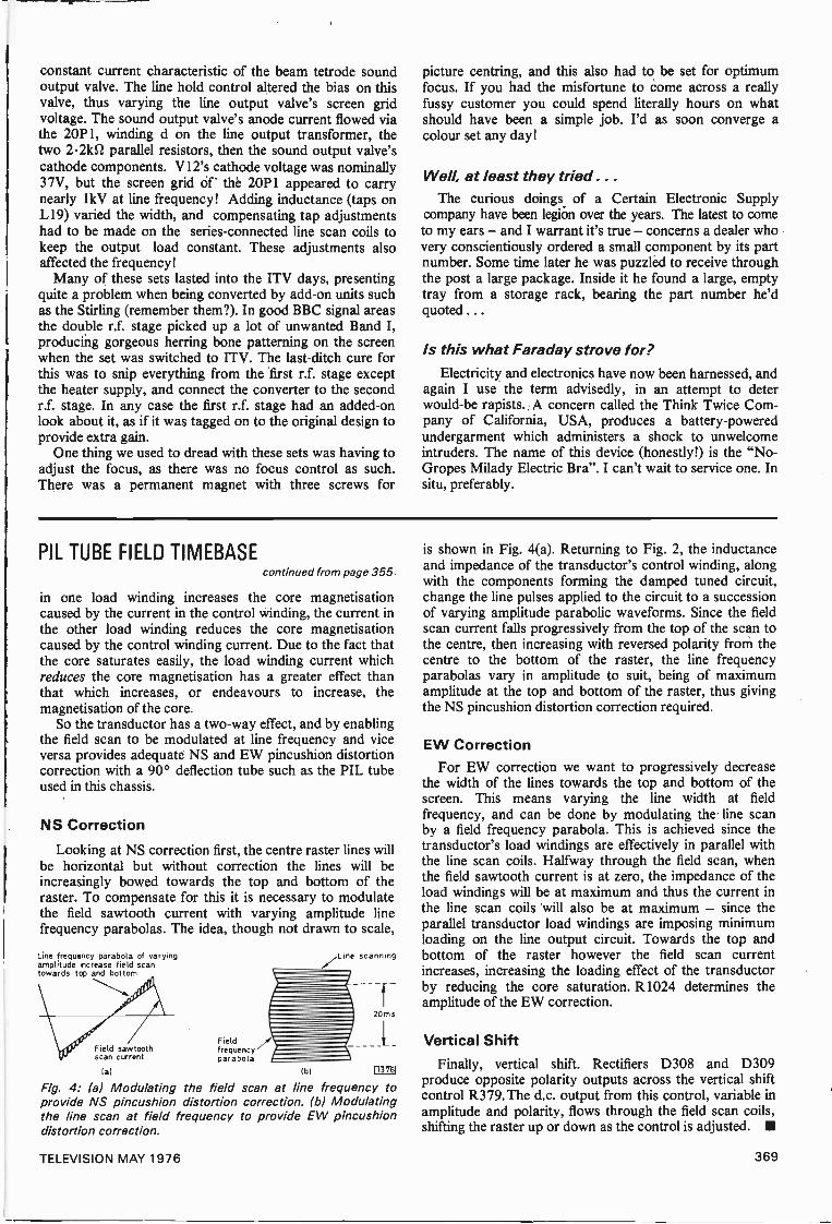
constant current characteristic of the beam tetrode soundoutput valve. The line hold control altered the bias on thisvalve, thus varying the line output valve's screen gridvoltage. The sound output valve's anode current flowed viathe 20P1, winding d on the line output transformer, thetwo 2.21d2 parallel resistors, then the sound output valve'scathode components. V12's cathode voltage was nominally37V, but the screen grid of the 20P1 appeared to carrynearly 1kV at line frequency! Adding inductance (taps onL19) varied the width, and compensating tap adjustmentshad to be made on the series -connected line scan coils tokeep the output load constant. These adjustments alsoaffected the frequency!
Many of these sets lasted into the ITV days, presentingquite a problem when being converted by add-on units suchas the Stirling (remember them?). In good BBC signal areasthe double r.f. stage picked up a lot of unwanted Band I,producing gorgeous herring bone patterning on the screenwhen the set was switched to ITV. The last-ditch cure forthis was to snip everything from the first r.f. stage exceptthe heater supply, and connect the converter to the secondr.f. stage. In any case the first r.f. stage had an added -onlook about it, as if it was tagged on to the original design toprovide extra gain.
One thing we used to dread with these sets was having toadjust the focus, as there was no focus control as such.There was a permanent magnet with three screws for
picture centring, and this also had to be set for optimumfocus. If you had the misfortune to come across a reallyfussy customer you could spend literally hours on whatshould have been a simple job. I'd as soon converge acolour set any day!
Well, at least they tried . . .
The curious doings of a Certain Electronic Supplycompany have been legion over the years. The latest to cometo my ears - and I warrant it's true - concerns a dealer whovery conscientiously ordered a small component by its partnumber. Some time later he was puzzled to receive throughthe post a large package. Inside it he found a large, emptytray from a storage rack, bearing the part number he'dquoted ...
Is this what Faraday strove for?Electricity and electronics have now been harnessed, and
again I use the term advisedly, in an attempt to deterwould-be rapists. A concern called the Think Twice Com-pany of California, USA, produces a battery -poweredundergarment which administers a shock to unwelcomeintruders. The name of this device (honestly!) is the "No -Gropes Milady Electric Bra". I can't wait to service one. Insitu, preferably.
PIL TUBE FIELD TIMEBASEcontinued from page 355
in one load winding increases the core magnetisationcaused by the current in the control winding, the current inthe other load winding reduces the core magnetisationcaused by the control winding current. Due to the fact thatthe core saturates easily, the load winding current whichreduces the core magnetisation has a greater effect thanthat which increases, or endeavours to increase, themagnetisation of the core.
So the transductor has a two-way effect, and by enablingthe field scan to be modulated at line frequency and viceversa provides adequate NS and EW pincushion distortioncorrection with a 90° deflection tube such as the PIL tubeused in this chassis.
NS Correction
Looking at NS correction first, the centre raster lines willbe horizontal but without correction the lines will beincreasingly bowed towards the top and bottom of theraster. To compensate for this it is necessary to modulatethe field sawtooth current with varying amplitude linefrequency parabolas. The idea, though not drawn to scale,
Line frequency parabola of varyingamplitude increase field scantowards top and bottom
Field sawtoothscan current
(a)
Fieldfrequencyparabola
lb)
Fig. 4: (a) Modulating the field scan at line frequency toprovide NS pincushion distortion correction. (b) Modulatingthe line scan at field frequency to provide EW pincushiondistortion correction.
Line scanning
20ms
ri376J
is shown in Fig. 4(a). Returning to Fig. 2, the inductanceand impedance of the transductor's control winding, alongwith the components forming the damped tuned circuit,change the line pulses applied to the circuit to a successionof varying amplitude parabolic waveforms. Since the fieldscan current falls progressively from the top of the scan tothe centre, then increasing with reversed polarity from thecentre to the bottom of the raster, the line frequencyparabolas vary in amplitude to suit, being of maximumamplitude at the top and bottom of the raster, thus givingthe NS pincushion distortion correction required.
EW CorrectionFor EW correction we want to progressively decrease
the width of the lines towards the top and bottom of thescreen. This means varying the line width at fieldfrequency, and can be done by modulating the line scanby a field frequency parabola. This is achieved since thetransductor's load windings are effectively in parallel withthe line scan coils. Halfway through the field scan, whenthe field sawtooth current is at zero, the impedance of theload windings will be at maximum and thus the current inthe line scan coils will also be at maximum - since theparallel transductor load windings are imposing minimumloading on the line output circuit. Towards the top andbottom of the raster however the field scan currentincreases, increasing the loading effect of the transductorby reducing the core saturation. R1024 determines theamplitude of the EW correction.
Vertical ShiftFinally, vertical shift. Rectifiers D308 and D309
produce opposite polarity outputs across the vertical shiftcontrol R379. The d.c. output from this control, variable inamplitude and polarity, flows through the field scan coils,shifting the raster up or down as the control is adjusted. III
TELEVISION MAY 1976 369
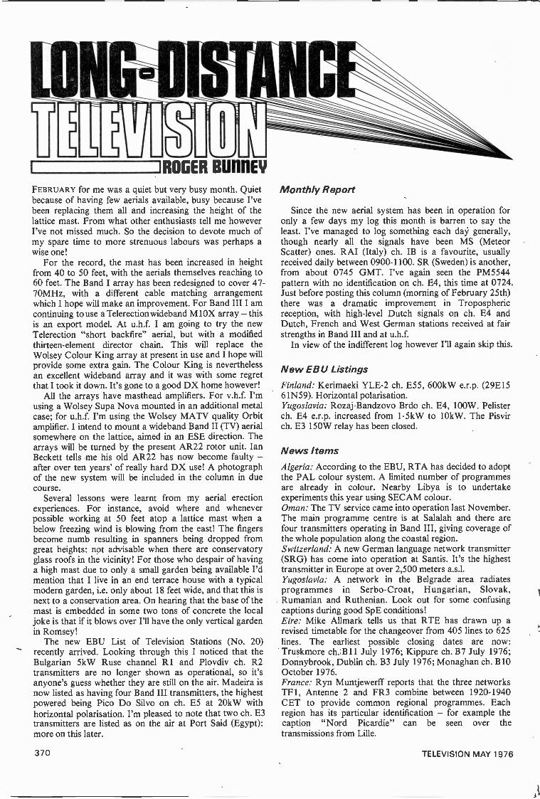
ROGER BUI1NEY
FEBRUARY for me was a quiet but very busy month. Quietbecause of having few aerials available, busy because I'vebeen replacing them all and increasing the height of thelattice mast. From what other enthusiasts tell me howeverI've not missed much. So the decision to devote much ofmy spare time to more strenuous labours was perhaps awise one!
For the record, the mast has been increased in heightfrom 40 to 50 feet, with the aerials themselves reaching to60 feet. The Band I array has been redesigned to cover 47-70MHz, with a different cable matching arrangementwhich I hope will make an improvement. For Band III I amcontinuing to use a Telerectionwideband M1OX array - thisis an export model. At u.h.f. I am going to try the newTelerection "short backfire" aerial, but with a modifiedthirteen -element director chain. This will replace theWolsey Colour King array at present in use and I hope willprovide some extra gain. The Colour King is neverthelessan excellent wideband array and it was with some regretthat I took it down. It's gone to a good DX home however!
All the arrays have masthead amplifiers. I'musing a Wolsey Supa Nova mounted in an additional metalcase; for u.h.f. I'm using the Wolsey MATV quality Orbitamplifier. I intend to mount a wideband Band II (TV) aerialsomewhere on the lattice, aimed in an ESE direction. Thearrays will be turned by the present AR22 rotor unit. IanBeckett tells me his old AR22 has now become faulty -after over ten years' of really hard DX use! A photographof the new system will be included in the column in duecourse.
Several lessons were learnt from my aerial erectionexperiences. For instance, avoid where and wheneverpossible working at 50 feet atop a lattice mast when abelow freezing wind is blowing from the east! The fingersbecome numb resulting in spanners being dropped fromgreat heights: not advisable when there are conservatoryglass roofs in the vicinity! For those who despair of havinga high mast due to only a small garden being available I'dmention that I live in an end terrace house with a typicalmodern garden, i.e. only about 18 feet wide, and that this isnext to a conservation area. On hearing that the base of themast is embedded in some two tons of concrete the localjoke is that if it blows over I'll have the only vertical gardenin Romsey!
The new EBU List of Television Stations (No. 20)recently arrived. Looking through this I noticed that theBulgarian 5kW Ruse channel R1 and Plovdiv ch. R2transmitters are no longer shown as operational, so it'sanyone's guess whether they are still on the air. Madeira isnow listed as having four Band III transmitters, the highestpowered being Pico Do Silvo on ch. ES at 20kW withhorizontal polarisation. I'm pleased to note that two ch. E3transmitters are listed as on the air at Port Said (Egypt):more on this later.
Monthly Report
Since the new aerial system has been in operation foronly a few days my log this month is barren to say theleast. I've managed to log something each day generally,though nearly all the signals have been MS (MeteorScatter) ones. RAI (Italy) ch. IB is a favourite, usuallyreceived daily between 0900-1100. SR (Sweden) is another,from about 0745 GMT. I've again seen the PM5544pattern with no identification on ch. E4, this time at 0724.Just before posting this column (morning of February 25th)there was a dramatic improvement in Troposphericreception, with high-level Dutch signals on ch. E4 andDutch, French and West German stations received at fairstrengths in Band III and at u.h.f.
In view of the indifferent log however I'll again skip this.
New EBU ListingsFinland: Kerimaeki YLE-2 ch. E55, 600kW e.r.p. (29E1561N59).Yugoslavia: Rozaj-Bandzovo Brdo ch. E4, 100W. Pelisterch. E4 e.r.p. increased from 1.5kW to 10kW. The Pisvirch. E3 150W relay has been closed.
News ItemsAlgeria: According to the EBU, RTA has decided to adoptthe PAL colour system. A limited number of programmesare already in colour. Nearby Libya is to undertakeexperiments this year using SECAM colour.Oman: The TV service came into operation last November.The main programme centre is at Salalah and there arefour transmitters operating in Band III, giving coverage ofthe whole population along the coastal region.Switzerland: A new German language network transmitter(SRG) has come into operation at Santis. It's the highesttransmitter in Europe at over 2,500 meters a.s.l.Yugoslavia: A network in the Belgrade area radiatesprogrammes in Serbo-Croat, Hungarian, Slovak,Rumanian and Ruthenian. Look out for some confusingcaptions during good SpE conditions!Eire: Mike Allmark tells us that RTE has drawn up arevised timetable for the changeover from 405 lines to 625lines. The earliest possible closing dates are now:Truskmore ch. B11 July 1976; Kippure ch. B7 July 1976;Donnybrook, Dublin ch. B3 July 1976; Monaghan ch. B10October 1976.France: Ryn Muntjewerff reports that the three networksTF1, Antenne 2 and FR3 combine between 1920-1940CET to provide common regional programmes. Eachregion has its particular identification - for example thecaption "Nord Picardie" can be seen over thetransmissions from Lille.
370 TELEVISION MAY 1976
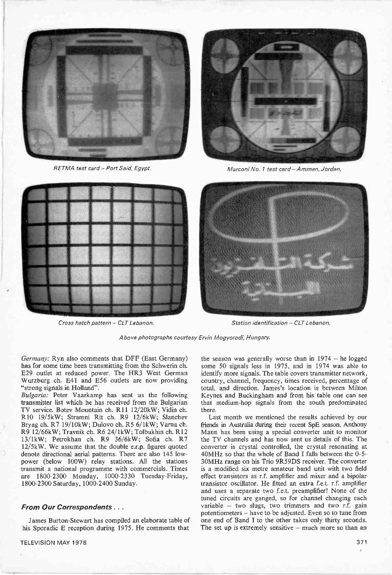
RETMA test card - Port Said, Egypt.
Cross hatch pattern - CLT Lebanon.
Marconi No. 1 test card -Amman, Jordan.
Station identification - CLT Lebanon.
Above photographs courtesy Ervin Mogyorodi, Hungary.
Germany: Ryn also comments that DFF (East Germany)has for some time been transmitting from the Schwerin ch.E29 outlet at reduced power. The HR3 West GermanWurzburg ch. E41 and E56 outlets are now providing"strong signals in Holland".Bulgaria: Peter Vaarkamp has sent us the followingtransmitter list which he has received from the BulgarianTV service. Botev Mountain ch. R11 12/20kW; Vidin ch.R10 19/5kW; Stramni Rit ch. R9 12/6kW; SlanchevBryag ch. R7 19/10kW; Dulovo ch. R5 6/1kW; Varna ch.R9 12/66kW; Travnik ch. R6 24/1kW; Tolbukhin ch. R1213/1kW; Petrokhan ch. R9 36/6kW; Sofia ch. R712/5kW. We assume that the double e.r.p. figures quoteddenote directional aerial patterns. There are also 145 low -power (below 100W) relay stations. All the stationstransmit a national programme with commercials. Timesare 1800-2300 Monday, 1000-2330 Tuesday -Friday,1800-2300 Saturday, 1000-2400 Sunday.
From Our Correspondents . . .
James Burton -Stewart has compiled an elaborate table ofhis Sporadic E reception during 1975. He comments that
the season was generally worse than in 1974 - he loggedsome 50 signals less in 1975, and in 1974 was able toidentify more signals. The table covers transmitter network,country, channel, frequency, times received, percentage oftotal, and direction. James's location is between MiltonKeynes and Buckingham and from his table one can seethat medium -hop signals from the south predominatedthere.
Last month we mentioned the results achieved by ourfriends in Australia during their recent SpE season. AnthonyMann has been using a special converter unit to monitorthe TV channels and has now sent us details of this. Theconverter is crystal controlled, the crystal resonating at40MHz so that the whole of Band I falls between the 0.5-30MHz range on his Trio 9R59DS receiver. The converteris a modified six metre amateur band unit with two fieldeffect transistors as r.f. amplifier and mixer and a bipolartransistor oscillator. He fitted an extra f.e.t. r.f. amplifierand uses a separate two f.e.t. preamplifier! None of thetuned circuits are ganged, so for channel changing eachvariable - two slugs, two trimmers and two r.f. gainpotentiometers - have to be adjusted. Even so to tune fromone end of Band I to the other takes only thirty seconds.The set up is extremely sensitive - much more so than an
TELEVISION MAY 1976 371
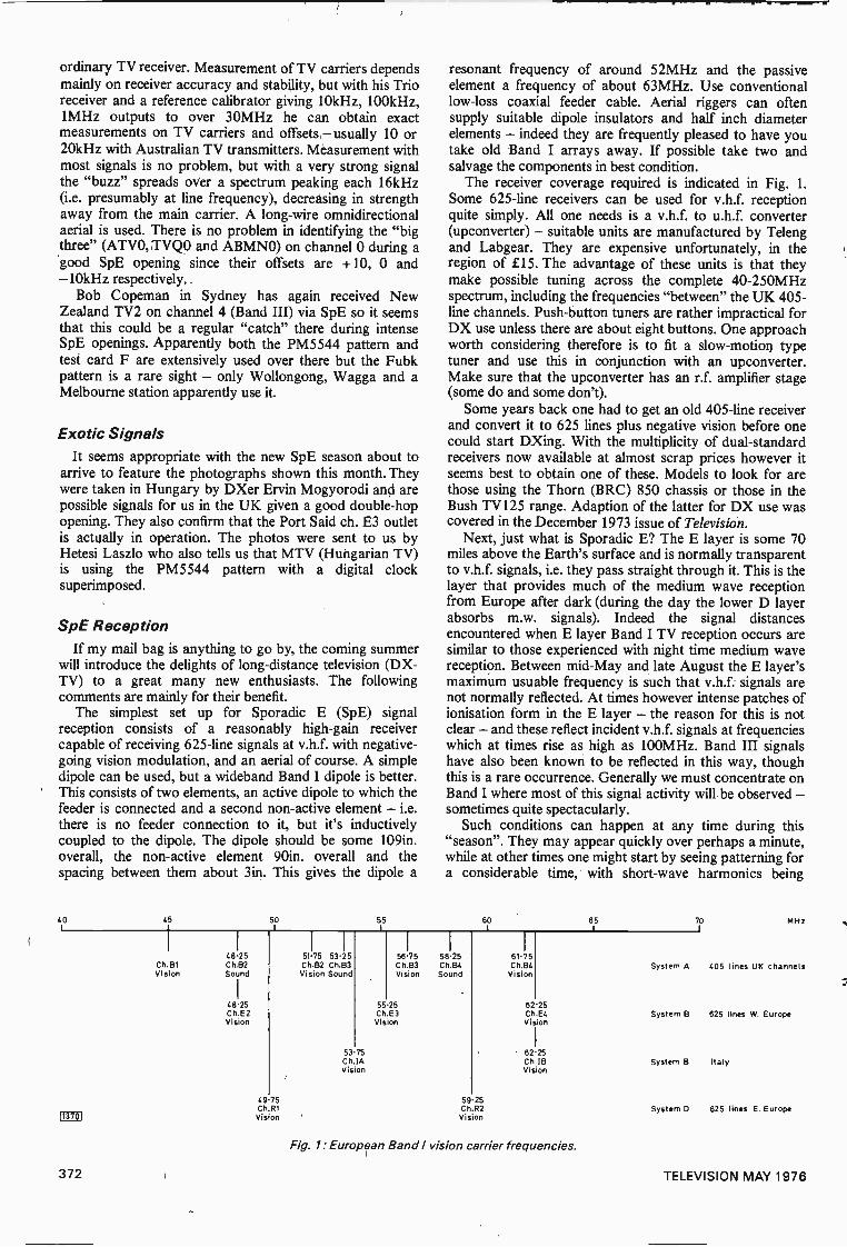
ordinary TV receiver. Measurement of TV carriers dependsmainly on receiver accuracy and stability, but with his Trioreceiver and a reference calibrator giving 10kHz, 100kHz,1MHz outputs to over 30MHz he can obtain exactmeasurements on TV carriers and offsets-usually 10 or20kHz with Australian TV transmitters. Measurement withmost signals is no problem, but with a very strong signalthe "buzz" spreads over a spectrum peaking each 16kHz(i.e. presumably at line frequency), decreasing in strengthaway from the main carrier. A long-wire omnidirectionalaerial is used. There is no problem in identifying the "bigthree" (ATVO, TVQO and ABMNO) on channel 0 during agood SpE opening since their offsets are +10, 0 and-10kHz respectively.
Bob Copeman in Sydney has again received NewZealand TV2 on channel 4 (Band III) via SpE so it seemsthat this could be a regular "catch" there during intenseSpE openings. Apparently both the PM5544 pattern andtest card F are extensively used over there but the Fubkpattern is a rare sight - only Wollongong, Wagga and aMelbourne station apparently use it.
Exotic SignalsIt seems appropriate with the new SpE season about to
arrive to feature the photographs shown this month. Theywere taken in Hungary by DXer Ervin Mogyorodi and arepossible signals for us in the UK given a good double -hopopening. They also confirm that the Port Said ch. E3 outletis actually in operation. The photos were sent to us byHetesi Laszlo who also tells us that MTV (Hungarian TV)is using the PM5544 pattern with a digital clocksuperimposed.
SpE ReceptionIf my mail bag is anything to go by, the coming summer
will introduce the delights of long-distance television (DX -TV) to a great many new enthusiasts. The followingcomments are mainly for their benefit.
The simplest set up for Sporadic E (SpE) signalreception consists of a reasonably high -gain receivercapable of receiving 625 -line signals at v.h.f. with negative -going vision modulation, and an aerial of course. A simpledipole can be used, but a wideband Band I dipole is better.This consists of two elements, an active dipole to which thefeeder is connected and a second non -active element - i.e.there is no feeder connection to it, but it's inductivelycoupled to the dipole. The dipole should be some 109in.overall, the non -active element 90in. overall and thespacing between them about 3in. This gives the dipole a
resonant frequency of around 52MHz and the passiveelement a frequency of about 63MHz. Use conventionallow -loss coaxial feeder cable. Aerial riggers can oftensupply suitable dipole insulators and half inch diameterelements - indeed they are frequently pleased to have youtake old Band I arrays away. If possible take two andsalvage the components in best condition.
The receiver coverage required is indicated in Fig. 1.
Some 625 -line receivers can be used for v.h.f. receptionquite simply. All one needs is a v.h.f. to u.h.f. converter(upconverter) - suitable units are manufactured by Telengand Labgear. They are expensive unfortunately, in theregion of £15. The advantage of these units is that theymake possible tuning across the complete 40-250MHzspectrum, including the frequencies "between" the UK 405 -line channels. Push-button tuners are rather impractical forDX use unless there are about eight buttons. One approachworth considering therefore is to fit a slow-motion typetuner and use this in conjunction with an upconverter.Make sure that the upconverter has an r.f. amplifier stage(some do and some don't).
Some years back one had to get an old 405 -line receiverand convert it to 625 lines plus negative vision before onecould start DXing. With the multiplicity of dual -standardreceivers now available at almost scrap prices however itseems best to obtain one of these. Models to look for arethose using the Thorn (BRC) 850 chassis or those in theBush TV125 range. Adaption of the latter for DX use wascovered in the December 1973 issue of Television.
Next, just what is Sporadic E? The E layer is some 70miles above the Earth's surface and is normally transparentto v.h.f. signals, i.e. they pass straight through it. This is thelayer that provides much of the medium wave receptionfrom Europe after dark (during the day the lower D layer
encountered when E layer Band I TV reception occurs aresimilar to those experienced with night time medium wavereception. Between mid -May and late August the E layer'smaximum usuable frequency is such that v.h.f. signals arenot normally reflected. At times however intense patches ofionisation form in the E layer - the reason for this is notclear - and these reflect incident v.h.f. signals at frequencieswhich at times rise as high as 100MHz. Band III signalshave also been known to be reflected in this way, thoughthis is a rare occurrence. Generally we must concentrate onBand I where most of this signal activity will be observed -sometimes quite spectacularly.
Such conditions can happen at any time during this"season". They may appear quickly over perhaps a minute,while at other times one might start by seeing patterning fora considerable time, with short-wave harmonics being
GO 45I
5,19 55 60 65I 70 MHz
48.25 51.75 53.25 56.75 58.25 61.75Ch.B1 Ch.B2 Ch.B2 Ch.B3 Ch.B3 Ch.& Ch.B4 System A 405 lines UK channelsVision Sound Vision Sound Vision Sound Vision
48.25 55.25 62.25Ch.E2 Ch.E3 Ch.64 System B 625 lines W. EuropeVision Vision Vision
53 75 62.25Ch.IB System B Italy
Vision Vision
49 75 59.25Ch R1 C h.R2 System D 625 lines E. Europe
113701 Vision Vision
Fig. 1: European Band / vision carrier frequencies.
372 TELEVISION MAY 1976
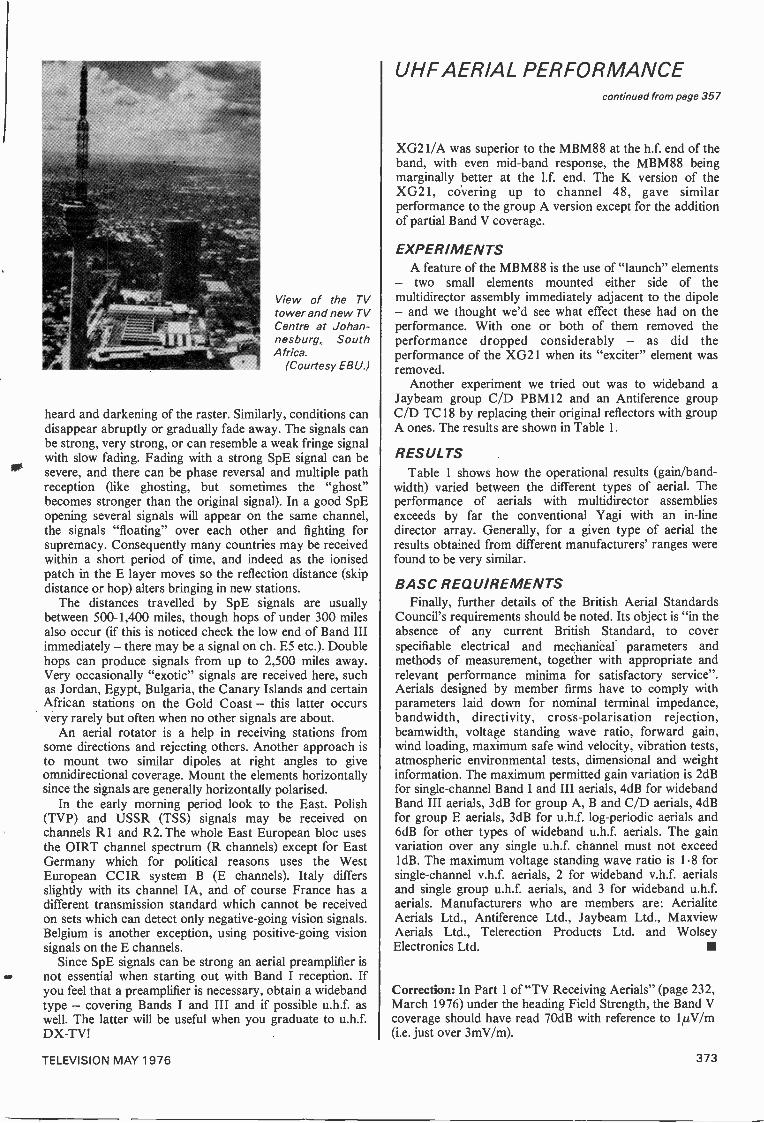
View of the TVtower and new TVCentre at Johan-nesburg, SouthAfrica.
(Courtesy EB U.)
heard and darkening of the raster. Similarly, conditions candisappear abruptly or gradually fade away. The signals canbe strong, very strong, or can resemble a weak fringe signalwith slow fading. Fading with a strong SpE signal can besevere, and there can be phase reversal and multiple pathreception (like ghosting, but sometimes the "ghost"becomes stronger than the original signal). In a good SpEopening several signals will appear on the same channel,the signals "floating" over each other and fighting forsupremacy. Consequently many countries may be receivedwithin a short period of time, and indeed as the ionisedpatch in the E layer moves so the reflection distance (skipdistance or hop) alters bringing in new stations.
The distances travelled by SpE signals are usuallybetween 500-1,400 miles, though hops of under 300 milesalso occur (if this is noticed check the low end of Band IIIimmediately - there may be a signal on ch. E5 etc.). Doublehops can produce signals from up to 2,500 miles away.Very occasionally "exotic" signals are received here, suchas Jordan, Egypt, Bulgaria, the Canary Islands and certainAfrican stations on the Gold Coast - this latter occursvery rarely but often when no other signals are about.
An aerial rotator is a help in receiving stations fromsome directions and rejecting others. Another approach isto mount two similar dipoles at right angles to giveomnidirectional coverage. Mount the elements horizontallysince the signals are generally horizontally polarised.
In the early morning period look to the East. Polish(TVP) and USSR (TSS) signals may be received onchannels R1 and R2. The whole East European bloc usesthe OIRT channel spectrum (R channels) except for EastGermany which for political reasons uses the WestEuropean CCIR system B (E channels). Italy differsslightly with its channel IA, and of course France has adifferent transmission standard which cannot be receivedon sets which can detect only negative -going vision signals.Belgium is another exception, using positive -going visionsignals on the E channels.
Since SpE signals can be strong an aerial preamplifier isnot essential when starting out with Band I reception. Ifyou feel that a preamplifier is necessary, obtain a widebandtype - covering Bands I and III and if possible u.h.f. aswell. The latter will be useful when you graduate to u.h.f.DX -TV!
UHF AERIAL PERFORMANCEcontinued from page 357
XG21/A was superior to the MBM88 at the h.f. end of theband, with even mid -band response, the MBM88 beingmarginally better at the 1.f. end. The K version of theXG21, covering up to channel 48, gave similarperformance to the group A version except for the additionof partial Band V coverage.
EXPERIMENTSA feature of the MBM88 is the use of "launch" elements
- two small elements mounted either side of themultidirector assembly immediately adjacent to the dipole- and we thought we'd see what effect these had on theperformance. With one or both of them removed theperformance dropped considerably - as did theperformance of the XG21 when its "exciter" element wasremoved.
Another experiment we tried out was to wideband aJaybeam group C/D PBM12 and an Antiference groupC/D TC18 by replacing their original reflectors with groupA ones. The results are shown in Table 1.
RESULTSTable 1 shows how the operational results (gain/band-
width) varied between the different types of aerial. Theperformance of aerials with multidirector assembliesexceeds by far the conventional Yagi with an in -linedirector array. Generally, for a given type of aerial theresults obtained from different manufacturers' ranges werefound to be very similar.
BASC REQUIREMENTSFinally, further details of the British Aerial Standards
Council's requirements should be noted. Its object is "in theabsence of any current British Standard, to coverspecifiable electrical and meehanical parameters andmethods of measurement, together with appropriate andrelevant performance minima for satisfactory service".Aerials designed by member firms have to comply withparameters laid down for nominal terminal impedance,bandwidth, directivity, cross -polarisation rejection,beamwidth, voltage standing wave ratio, forward gain,wind loading, maximum safe wind velocity, vibration tests,atmospheric environmental tests, dimensional and weightinformation. The maximum permitted gain variation is 2dBfor single -channel Band I and III aerials, 4dB for widebandBand III aerials, 3dB for group A, B and C/D aerials, 4dBfor group E aerials, 3dB for u.h.f. log -periodic aerials and6dB for other types of wideband u.h.f. aerials. The gainvariation over any single u.h.f. channel must not exceed1dB. The maximum voltage standing wave ratio is 1.8 forsingle -channel v.h.f. aerials, 2 for wideband v.h.f. aerialsand single group u.h.f. aerials, and 3 for wideband u.h.f.aerials. Manufacturers who are members are: AerialiteAerials Ltd., Antiference Ltd., Jaybeam Ltd., MaxviewAerials Ltd., Telerection Products Ltd. and WolseyElectronics Ltd.
Correction: In Part 1 of "TV Receiving Aerials" (page 232,March 1976) under the heading Field Strength, the Band Vcoverage should have read 70dB with reference to 1pV/m(i.e. just over 3mV/m).
TELEVISION MAY 1976 373
TANDBERGCTV2-2CHASSIS=rz
THE Norwegian firm Tandberg is probably best known forits audio and tape recording equipment. It also produceshigh quality colour television receivers however and twochassis have been used in the Tandberg models distributedin the UK, a hybrid one in their earlier 90° models and asolid-state chassis in their current 110° models. We aredealing with the solid-state CTV2-2 chassis in this presentarticle.
The circuitry is typical of modern European colourreceiver design, with a switch -mode regulated powersupply, single transistor line output stage with diode widthmodulator to provide EW pincushion distortion correction,and varicap tuners, extensive use being made of i.c.s -especially in the decoder.
Most of the circuitry is carried on the hinged mainchassis, which can be swung down to gain access. The lineoutput, e.h.t. and associated components are on a printedpanel on the right-hand side, the field output, luminanceand RGB output stages being on the left-hand side. Thetuners, i.f. strip, decoder, sound channel and line oscillatorcircuit are on printed circuit modules which plug into theleft-hand side of the chassis.
The regulated power supply is in a screenedcompartment at the bottom of the chassis. It's fed from abridge rectifier which in most models is mounted on a smallboard at the bottom of the cabinet, along with the c.r.t.heater transformer and the degaussing circuitry.
It is recommended that an isolating transformer is usedwhen servicing these sets since with a bridge rectifierdirectly across the mains input the chassis is live to bothsides of the mains supply.
Signal Circuits
The signal circuits are relatively conventional. There areseparate v.h.f. and u.h.f. varicap tuners, a discretetransistor i.f. strip and a TCA270 i.c. to providesynchronous vision demodulation, a.f.c. and a.g.c.
Apart from occasional tuner trouble such as tuning driftand low gain this section of the receiver gives very littletrouble, the usual complaint of poor picture due tomistuning being cured by adjusting the a.f.c. discriminatorcoil L16 which is adjacent to the TCA270.
No sound or intermittent sound faults have usually beenrectified by changing the TBA120AS intercarrier sound i.c.(circuit reference U101), the audio preamplifier transistorQ151 (BC149) or the driver transistor Q152 (BC328).Sound distortion, often intermittent, is quite often due tothe loudspeaker.
There are several transistors along with the luminanceprocessing i.c. U200 (TBA500P) on the main printed boardon the left-hand side of the chassis. Along withamplification the TBA500P carries out black -level
clamping, peak white limiting and, in conjunction withQ203 (BC148B), beam limiting. Failure of Q203 results ina dark raster with no luminance, as does incorrectadjustment of its base preset control R207. If there isluminance but insufficient brightness on the other hand it islikely that the coarse brightness control R243 requiresadjustment.
Intermittent loss of luminance but with the colourinformation still present throws suspicion on the luminancedelay line FL200, especially if it is of the type whichresembles a black rod. These have also proved trouble-some in some other colour chassis of Scandinavian origin.
Decoder
The decoder consists of four i.c.s and their associatedcomponents. The TBA510, TBA540 and TBA990 are onone of the pluggable subassemblies: the final i.c. associatedwith decoding, the TBA530, is on the main left-hand panel.
Fault finding is easier if the functions of the i.c.s areunderstood. The TBA510 contains gain -controlledchrominance signal amplifiers, the colour -killer circuit, plusburst gating and blanking. The saturation control acts onthe chrominance channel in this i.c. The TBA540 is thereference oscillator with its associated phase detector andcontrol loop. A second detector in this i.c. produces thea.c.c. and colour -killer bias voltages and an ident biassignal. The TBA990 contains the PAL switch, thechrominance demodulators and the G -Y matrix. Inaddition to the three colour -difference signal outputs thereis a half line frequency squarewave output which is fedback to the a.c.c./ident/colour-killer detector in theTBA540. The TBA530 simply matrixes the luminance andcolour -difference signals to provide R, G, B output signals.
When working on the decoder it is useful to be able todisable the colour killer. To do this, open the link betweenpoints G1/1 and G1/2 on the decoder subpanel.
An unusual fault experienced several times has been toomuch colour with the a.c.c. not functioning, usually whenthe set is hot. On one occasion this happened on onechannel only. It can be remedied temporarily by sprayingthe TBA510 i.c. with freezer, and is a form of thermalrunaway in this i.c. To overcome the problem Tandbergrecommend changing the values of 4415 and R417associated with pins 11 and 12 from lk52 to 2.2k52. Thismodification is incorporated in later sets.
Otherwise, the few decoder faults encountered have beenstraightforward, such as faulty capacitors - for instance the18pF coupling capacitor C401 in the TBA510's inputcircuit.
In areas where the signal is poor we have had somecases where the decoder has been working satisfactorily butthe set has suffered from colour drop -out. In such cases the
374 TELEVISION MAY 1976
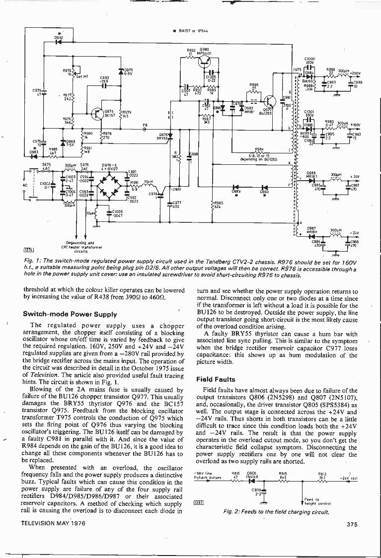
* BA157 or 1P644
D982
14
C975=47.**
C976i10
lYD983
R976lk
R9772k2
R9755k6
Set HT C980.068-11
Q975 IR979
D9756.8V
1BC157 k5
VD968a* 7.5V
R9864k7
R980 >R9781k 2270
P8
R992 098010 MPSUO1
C10050.22
eg iTiR.\".11129347 470 k
CJ20981
0'V AR997
3k3
R99627
C979
D9800977
1 TMR811 BU126S
.I.C981
2700P
1975
9
R991188
5975 300pH 5976 0976-9....,.... 4AT 2AT 4 x 81127r 9------c,03 C994
AC C1002dor0.1
0022
1-.47.-'
112741
C1004047
300p H
C9930022
10pC10060047
C9910022
R981
6.8
C9920022
10pH
Q9761,BRI55/
C978
R982
-280V
.1.C977400
C998
R984
6.8,10 or 15depending on BU126S
R98582k
14D989 099014
C1000330p
R989 3000a D984 22 +2501
b
BA159R988
.33k
C1001330 p
C983 C9892.2 10
R990 300uHD985 0.47 +160V
BYX55 C995-600
C98:r T2.222
D986MR811
Dega ssing andCRT heater transformer
circuits
d
C985470
D987MR 811
e
4,,
300pH
C990
T15
+ 24V
C987
T47°477
300pH- 24V
C986 C988470 470
Fig. 1: The switch -mode regulated power supply circuit used in the Tandberg CTV2-2 chassis. R976 should be set for 160Vh.t., a suitable measuring point being plug pin 02/6. All other output voltages will then be correct. R976 is accessible through ahole in the power supply unit cover: use an insulated screwdriver to avoid short-circuiting R976 to chassis.
threshold at which the colour killer operates can be loweredby increasing the value of R438 from 390Q to 460Q.
Switch -mode Power Supply
The regulated power supply uses a chopperarrangement, the chopper itself consisting of a blockingoscillator whose on/off time is varied by feedback to givethe required regulation. 160V, 250V and +24V and -24Vregulated supplies are given from a -280V rail provided bythe bridge rectifier across the mains input. The operation ofthe circuit was described in detail in the October 1975 issueof Television. The article also provided useful fault tracinghints. The circuit is shown in Fig. 1.
Blowing of the 2A mains fuse is usually caused byfailure of the BU126 chopper transistor Q977. This usuallydamages the BRY55 thyristor Q976 and the BC157transistor Q975. Feedback from the blocking oscillatortransformer T975 controls the conduction of Q975 whichsets the firing point of Q976 thus varying the blockingoscillator's triggering. The BU126 itself can be damaged bya faulty C981 in parallel with it. And since the value ofR984 depends on the gain of the BU126, it is a good idea tochange all these components whenever the BU126 has tobe replaced.
When presented with an overload, the oscillatorfrequency falls and the power supply produces a distinctivebuzz. Typical faults which can cause this condition in thepower supply are failure of any of the four supply railrectifiers D984/D985/D986/D987 or their associatedreservoir capacitors. A method of checking which supplyrail is causing the overload is to disconnect each diode in
turn and see whether the power supply operation returns tonormal. Disconnect only one or two diodes at a time sinceif the transformer is left without a load it is possible for theBU126 to be destroyed. Outside the power supply, the lineoutput transistor going short-circuit is the most likely causeof the overload condition arising.
A faulty BRY55 thyristor can cause a hum bar withassociated line sync pulling. This is similar to the symptomwhen the bridge rectifier reservoir capacitor C977 losescapacitance: this shows up as hum modulation of thepicture width.
Field Faults
Field faults have almost always been due to failure of theoutput transistors Q806 (2N5298) and Q807 (2N5107),and, occasionally, the driver transistor Q805 (SPS5384) aswell. The output stage is connected across the +24V and-24V rails. Thus shorts in both transistors can be a littledifficult to trace since this condition loads both the +24Vand -24V rails. The result is that the power supplyoperates in the overload cutout mode, so you don't get thecharacteristic field collapse symptom. Disconnecting thepower supply rectifiers one by one will not clear theoverload as two supply rails are shorted.
-58V lineflyback pulses
113831
R816 08061N414847
C809
R815 R8138k2 3k3 -24V rail
Feed toheight control
Fig. 2: Feeds to the field charging circuit.
TELEVISION MAY 1976 375
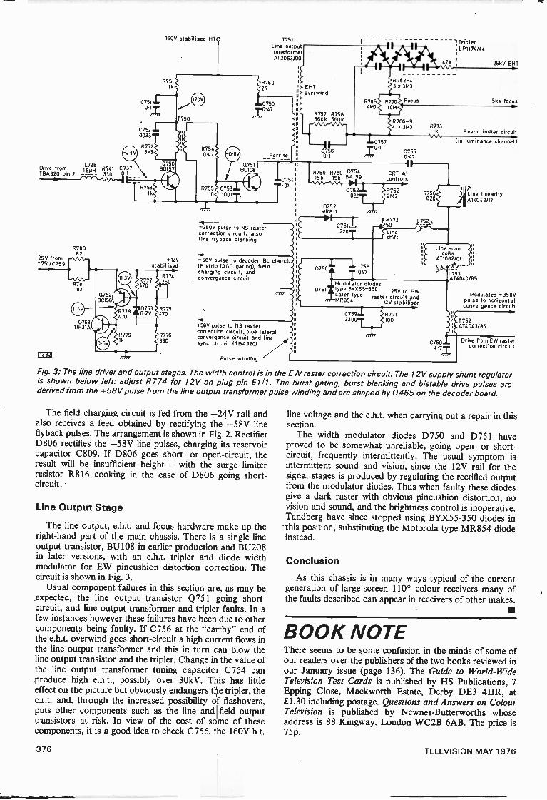
L7 25Drive from 160H R741 C737TBA920 pin 2 330 0-1
R76082
25V from1751/C759
0753T1P31A
)13821
160V stabilised
R75I
07511
0752 J.0033
R7523k3
T750
+I2Vstabilised
R774250
R775470
R776390
1751
Line out puttransformerAT2063/00
Ferrite
C 754".01
-350V pulse to NS rastercorrection circuit, alsoline flyback blanking
-58V pulse to decoder IBL clamp)IF strip IAGC gating), fieldcharging circuit, andconvergence circuit
+58V pulse to NS rastercorrection circuit, blue lateralconvergence circuit and linesync circuit ITBA920)
Pulse winding
0752MR811
R765 R770F°cus4M7 10M
ileC757
C762
1R766-93M3
C7550.47
CRT Alcontrols
R762022T 2M2
07611220T
D750 eleC758
R77250
Lineshift
R'17:13
R756820
L752
TriplerILP1174/44
47 25kV EHT
5kV focus
Beam limiter circuit
lin luminance channel)
Line linearityAT4042/12
Line scanco Is
AT1062/01
047 L753AT4040/85
Modulator diodesD751 type BYX55-350 25V to EWLater type raster circuit and
MR854 I2V stabiliser
07591 1R7712200T 100
C7604-7Z
Modulated +350Vpulse to horizontal
convergence circuit
T 752AT4043/86
Drive from EW rastercorrection circuit
Fig. 3: The line driver and output stages. The width control is in the EW raster correction circuit. The 12V supply shunt regulatoris shown below left: adjust R774 for 12V on plug pin E111. The burst gating, burst blanking and bistable drive pulses arederived from the +58V pulse from the line output transformer pulse winding and are shaped by Q465 on the decoder board.
The field charging circuit is fed from the -24V rail andalso receives a feed obtained by rectifying the -58V lineflyback pulses. The arrangement is shown in Fig. 2. RectifierD806 rectifies the -58V line pulses, charging its reservoircapacitor C809. If D806 goes short- or open -circuit, theresult will be insufficient height - with the surge limiterresistor R816 cooking in the case of D806 going short-circuit.
Line Output Stage
The line output, e.h.t. and focus hardware make up theright-hand part of the main chassis. There is a single lineoutput transistor, BU108 in earlier production and BU208in later versions, with an e.h.t. tripler and diode widthmodulator for EW pincushion distortion correction. Thecircuit is shown in Fig. 3.
Usual component failures in this section are, as may beexpected, the line output transistor Q751 going short-circuit, and line output transformer and tripler faults. In afew instances however these failures have been due to othercomponents being faulty. If C756 at the "earthy" end ofthe e.h.t. overwind goes short-circuit a high current flows inthe line output transformer and this in turn can blow theline output transistor and the tripler. Change in the value ofthe line output transformer tuning capacitor C754 canproduce high e.h.t., possibly over 30kV. This has littleeffect on the picture but obviously endangers the tripler, thec.r.t. and, through the increased possibility of flashovers,puts other components such as the line and field outputtransistors at risk. In view of the cost of some of thesecomponents, it is a good idea to check C756, the 160V h.t.
line voltage and the e.h.t. when carrying out a repair in thissection.
The width modulator diodes D750 and D751 haveproved to be somewhat unreliable, going open- or short-circuit, frequently intermittently. The usual symptom isintermittent sound and vision, since the 12V rail for thesignal stages is produced by regulating the rectified outputfrom the modulator diodes. Thus when faulty these diodesgive a dark raster with obvious pincushion distortion, novision and sound, and the brightness control is inoperative.Tandberg have since stopped using BYX55-350 diodes inthis position, substituting the Motorola type MR854 diodeinstead.
Conclusion
As this chassis is in many ways typical of the currentgeneration of large -screen 110° colour receivers many ofthe faults described can appear in receivers of other makes.
BOOK NOTEThere seems to be some confusion in the minds of some ofour readers over the publishers of the two books reviewed inour January issue (page 136). The Guide to World -WideTelevision Test Cards is published by HS Publications, 7Epping Close, Mackworth Estate, Derby DE3 4HR, atL1.30 including postage. Questions and Answers on ColourTelevision is published by Newnes-Butterworths whoseaddress is 88 Kingway, London WC2B 6AB. The price is75p.
376 TELEVISION MAY 1976
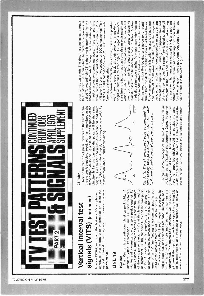
TV
TE
ST
PA
TT
ER
NS
SIG
NA
LSP
AR
T 2
CO
NT
INU
ED
FR
OM
OU
R
AP
RIL
197
6
SU
PP
LEM
EN
T
Ver
tical
inte
rval
test
sign
als
(VIT
S)
(con
tinue
d)H
AR
OLD
PE
TE
RS
, who
com
pile
d la
st m
onth
's s
uppl
emen
t,co
ntin
ues
this
mon
th w
ith in
form
atio
n on
usi
ng th
eve
rtic
alin
terv
alte
stsi
gnal
sto
asse
ssre
ceiv
erpe
rfor
man
ce.
LIN
E 1
9
10,u
s ba
rT
he 1
0ps
bar
is a
con
tinuo
us c
heck
on
peak
whi
te. A
stan
dard
vide
otr
ansm
issi
onlin
e,as
used
bet
wee
nst
udio
s an
d tr
ansm
itter
s, w
orks
to a
pea
k si
gnal
of 1
Vin
to 7
5 oh
ms.
Fro
m th
e to
p of
the
10ps
bar
to th
e bo
ttom
of th
e sy
nc p
ulse
is e
xact
ly 1
V a
nd th
is is
mai
ntai
ned
toan
acc
urac
y of
1%
, the
bar
bei
ng 0
-7V
and
the
sync
pul
se0-
3V. A
nybo
dy w
ho is
surp
rised
atth
is d
egre
e of
accu
racy
may
als
o be
ast
onis
hed
to r
ealis
e th
at a
1db
erro
r on
a 1
V li
ne fe
edin
g a
tran
smitt
er p
uttin
g ou
t50
0kW
can
mak
e a
diffe
renc
e of
100
kW to
the
e.r.
p.T
he b
ar a
lso
chec
ks th
e I.f
. and
tran
sien
t res
pons
es. I
tsto
p_ is
qui
te fl
at, a
nd th
e si
des
are
band
lim
ited
by s
ine
-sq
uarin
g (o
f whi
ch m
ore
anon
) so
that
its
corn
ers
are
undi
stor
ted.
The
effe
cts
of I.
f. di
stor
tion
will
be
seen
on
pict
ures
if th
e to
p of
the
bar
has
a sl
ope
of m
ore
than
2%
of it
s to
tal h
eigh
t, an
d tr
ansi
ent d
isto
rtio
n w
ill s
how
as
roun
ded
bar
corn
ers
or o
vers
hoot
s.
2T P
ulse
Nex
t to
the
bar
the
2T p
ulse
rep
rese
nts
the
fines
t det
ail
the
syst
em is
cap
able
of r
esol
ving
. It i
s tr
ansm
itted
at t
hesa
me
ampl
itude
as
the
10ps
bar
, so
if th
e re
spon
se o
f the
circ
uitr
y is
flat
the
bar
and
the
puls
e w
ill b
e th
e sa
me
heig
ht. L
ike
the
bar,
the
puls
e is
sin
esqu
ared
, and
ther
eno
w fo
llow
s a
slig
ht d
igre
ssio
n fo
r th
ose
who
wou
ld li
keto
kno
w m
ore
abou
t T a
nd s
ines
quar
ing.
(a)
(b)
(c)
1N29
41
Fig
.7:
(a)
The
2T
sin
esqu
ared
pul
se a
s ge
nera
ted.
(b)
Afte
r pa
ssin
g th
roug
h a
circ
uit w
ith a
sha
rp h
.f. c
utof
f.(c
) P
asse
d th
roug
h a
circ
uit o
f poo
r ov
eral
l res
pons
e.
To
gain
som
e co
ncep
t of t
he fi
nest
pos
sibl
e de
tail
avai
labl
e, tr
y to
vis
ualis
e th
e bo
ttom
5.2
MH
z fr
eque
ncy
grat
ings
of T
est C
ard
F. T
hese
are
sin
ewav
es -
and
thus
have
no
harm
onic
s w
hich
wou
ld fa
ll ou
tsid
e th
e ba
nd-
wid
th o
f the
sys
tem
. The
y re
pres
ent t
he ti
me
it ta
kes
the
scan
ning
spo
t to
mov
e ac
ross
the
scre
en b
y an
am
ount
equa
l to
its o
wn
wid
th. T
he ti
me
the
spot
take
s to
mov
eth
is d
ista
nce,
i.e.
from
whi
te to
bla
ck o
r vi
ce -
vers
a is
calle
d T
. Acc
ordi
ngly
2T
is th
e tim
e it
mus
t tak
e fo
r th
esp
ot to
mov
e fr
om w
hite
thro
ugh
blac
k to
whi
te a
gain
-in
oth
er w
ords
one
com
plet
e cy
cle.
If w
e ca
ll th
e fin
ede
tail
bars
of t
he te
st c
ard
5MH
z, a
sin
gle
cycl
e of
5M
Hz
will
take
1/5
of a
mic
rose
cond
or
200
nano
seco
nds.
Thi
sm
akes
T 1
00 n
anos
econ
ds a
nd 2
T 2
00 n
anos
econ
ds.
Now
abo
ut s
ines
quar
ing.
A s
inew
ave
cycl
e be
gins
at z
ero,
ris
es to
a p
ositi
vem
axim
um, p
asse
s ba
ck th
roug
h ze
ro to
a m
axim
umne
gativ
e an
d fa
lls to
zer
o ag
ain.
TV
sig
nals
, how
ever
,st
art f
rom
the
botto
m a
t bla
ck a
nd r
ise
to th
eir
max
imum
whi
ch is
whi
te. L
ooki
ng, t
hen,
at o
ur 5
MH
z fin
e de
tail
bars
, our
dat
um li
ne fo
r a
sing
le c
ycle
sta
rts
at b
asel
ine
(bla
ck),
ris
es to
whi
te a
nd fa
lls b
ack
to b
lack
. Mat
he-
mat
ical
ly a
sin
ewav
e st
artin
g fr
om o
ne e
xtre
mity
inst
ead
of th
e m
iddl
e at
trac
ts a
noth
er s
ine
func
tion
and
beco
mes
sine
squa
red.
It's
just
like
look
ing
at a
hor
se o
n a
roun
d-ab
out f
rom
the
deck
rat
her
than
from
an
adja
cent
hor
se.
To
gene
rate
suc
h a
wav
e it
is o
nly
nece
ssar
y to
gat
e ou
ton
e cy
cle
of a
sin
ewav
e tr
ain
star
ting
at th
e ne
gativ
epe
ak, b
ut in
pra
ctic
e it
is m
ore
conv
enie
nt to
pas
s a
shar
ptr
ansi
ent t
hrou
gh a
ban
d -li
miti
ng T
hom
pson
filte
r an
dta
ke w
hat c
omes
out
. The
sam
e fil
ter
is u
sed
to s
hape
all
tran
sien
ts in
the
two
lines
of w
avef
orm
s, s
o th
at n
othi
ngis
pre
sent
with
har
mon
ics
in e
xces
s of
5M
Hz
and
noth
ing
ente
rs th
e sy
stem
cap
able
of p
rodu
cing
dis
tort
ion.
The
re-
fore
if w
hat g
oes
in d
oes
not c
ome
out,
som
ethi
ng m
ust
have
alte
red
it in
bet
wee
n, F
ig. 7
.
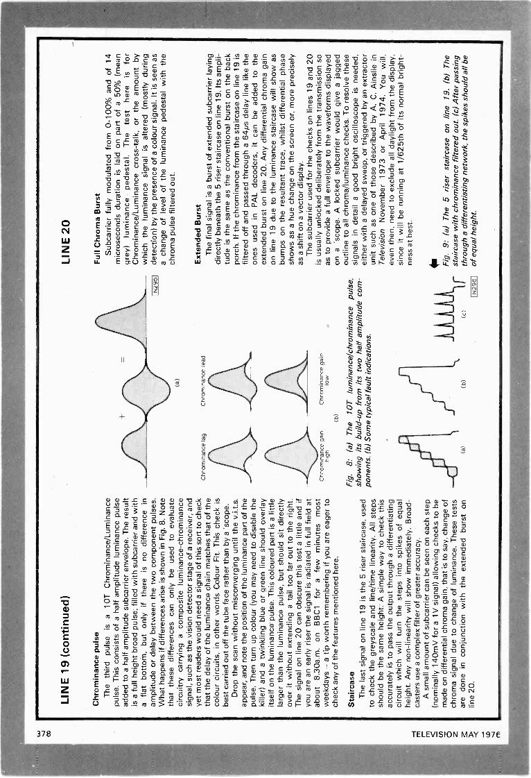
LIN
E 1
9 (c
ontin
ued)
Chr
omin
ance
pul
seT
he th
irdpu
lse
isa
10T
Chr
omin
ance
/Lum
inan
cepu
lse.
Thi
s co
nsis
ts o
f a h
alf a
mpl
itude
lum
inan
ce p
ulse
adde
d to
a h
alf a
mpl
itude
sub
carr
ier
enve
lope
. The
res
ult
is a
full
heig
ht b
road
pul
se, f
illed
with
sub
carr
ier
and
with
afla
tbo
ttom
, but
onl
yif
ther
eis
no
diffe
renc
ein
ampl
itude
or
dela
y be
twee
n th
e tw
o co
mpo
nent
pul
ses.
Wha
t hap
pens
if d
iffer
ence
s ar
ise
is s
how
n in
Fig
. 8. N
ote
that
thes
e di
ffere
nces
can
onl
y be
use
d to
eva
luat
eci
rcui
try
carr
ying
a c
ompo
site
lum
inan
ce-c
hrom
inan
cesi
gnal
, suc
h as
the
visi
on d
etec
tor
stag
e of
a r
ecei
ver,
and
yet m
ost r
eade
rs w
ould
nee
d a
sign
al o
f thi
s so
rt to
che
ckth
at th
e de
lay
of th
e lu
min
ance
cha
in m
atch
es th
at o
f the
colo
ur c
ircui
ts, i
n ot
her
wor
ds C
olou
r F
it. T
his
chec
k is
best
car
ried
out o
ff th
e tu
be fa
ce r
athe
r th
an b
y a
'sco
pe.
Dro
p th
e sc
an w
ithou
t mis
conv
ergi
ng u
ntil
the
v.i.t
.s.
appe
ar, a
nd n
ote
the
posi
tion
of th
e lu
min
ance
par
t of t
hepu
lse.
The
n tu
rn u
p co
lour
(yo
u m
ay n
eed
to d
isab
le th
eki
ller)
and
a tw
inkl
ing
blue
or
gree
n lin
e sh
ould
ove
rlay
itsel
f on
the
lum
inan
ce-
puls
e. T
his
colo
ured
par
t is
a lit
tlela
rger
than
the
lum
inan
ce p
ulse
, but
sho
uld
sit d
irect
lyov
er it
with
out e
xten
ding
a ta
il to
o fa
r ou
t to
the
right
.T
he s
igna
l on
line
20 c
an o
bscu
re th
is te
st a
littl
e an
d if
you
are
an e
arly
ris
er th
e si
gnal
is r
adia
ted
in fu
ll fie
ld a
tab
out 8
.30a
.m. o
n B
BC
1fo
ra
few
min
utes
mos
tw
eekd
ays
-a ti
p w
orth
rem
embe
ring
if yo
u ar
e ea
ger
toch
eck
any
of th
e fe
atur
es m
entio
ned
here
.
Sta
ircas
eT
he la
st s
igna
l on
line
19 is
the
5 ris
er s
tairc
ase,
use
dto
che
ck th
e gr
eysc
ale
and
line/
time
linea
rity.
All
step
ssh
ould
be
the
sam
e he
ight
. A s
impl
e w
ay to
che
ck th
isac
cura
tely
is to
pas
s th
e ou
tput
thro
ugh
a di
ffere
ntia
ting
circ
uit w
hich
will
turn
the
step
s in
to s
pike
s of
equ
alhe
ight
. Any
non
-lin
earit
y w
ill s
how
imm
edia
tely
. Bro
ad-
cast
ers
use
a co
mpl
ex fi
lter
of g
reat
er a
ccur
acy.
A s
mal
l am
ount
of s
ubca
rrie
r ca
n be
see
n on
eac
h st
ep(n
omin
ally
140
mV
for
a 1V
sig
nal)
allo
win
g ch
ecks
to b
em
ade
on d
iffer
entia
l chr
oma
gain
, tha
t is
to s
ay, c
hang
e of
chro
ma
sign
al d
ue to
cha
nge
of lu
min
ance
. The
se te
sts
are
done
in c
onju
nctio
n w
ith th
e ex
tend
ed b
urst
on
line
20.
Chr
omin
ance
lag
Chr
omin
ance
gai
nhi
gh(b
)
(a)
Chr
omin
ance
lead
Chr
omin
ance
gai
nlO
w
Fig
.8:
(a)
The
10T
lum
inan
ce/c
hrom
inan
ce p
ulse
,sh
owin
g its
bui
ld-u
p fr
om it
s tw
o ha
lf am
plitu
de c
om-
pone
nts.
(b)
Som
e ty
pica
l fau
lt in
dica
tions
.
(a)
(c)
IN
2961
LIN
E 2
0
Ful
l Chr
oma
Bur
stS
ubca
rrie
r fu
lly m
odul
ated
from
0-1
00%
and
of 1
4m
icro
seco
nds
dura
tion
is la
id o
n pa
rt o
f a 5
0% (
mea
ngr
ey)
lum
inan
cepe
dest
al.
The
test
here
isfo
rC
hrom
inan
ce/L
umin
ance
cro
ss -
talk
, or
the
amou
nt b
yw
hich
the
lum
inan
ce s
igna
lis
alte
red
(mos
tly d
urin
gde
tect
ion)
by
the
pres
ence
of a
col
our
sign
al. I
t is
seen
as
a ch
ange
of l
evel
of t
he lu
min
ance
ped
esta
l with
the
chro
ma
puls
e fil
tere
d ou
t.
Ext
ende
d B
urst
The
fina
l sig
nal i
s a
burs
t of e
xten
ded
subc
arrie
r la
ying
dire
ctly
ben
eath
the
5 ris
er s
tairc
ase
on li
ne 1
9. It
s am
pli-
tude
is th
e sa
me
as th
e co
nven
tiona
l bur
st o
n th
e ba
ckpo
rch.
If th
e ch
rom
inan
ce fr
om th
e st
airc
ase
on li
ne 1
9 is
filte
red
off a
nd p
asse
d th
roug
h a
64ps
del
ay li
ne li
ke th
eon
es u
sed
in P
AL
deco
ders
,it
can
be a
dded
to th
eex
tend
ed b
urst
on
line
20. A
ny d
iffer
entia
l chr
oma
gain
on li
ne 1
9 du
e to
the
lum
inan
ce s
tairc
ase
will
sho
w a
sbu
mps
on
the
resu
ltant
trac
e, w
hils
t diff
eren
tial p
hase
show
s as
a h
ue c
hang
e on
the
scre
en o
r, m
ore
prec
isel
yas
a s
hift
on a
vec
tor
disp
lay.
The
sub
carr
ier
used
for
the
chec
ks o
n lin
es 1
9 an
d 20
is u
sual
ly u
nloc
ked
delib
erat
ely
from
the
tran
smis
sion
so
as to
pro
vide
a fu
ll en
velo
pe to
the
wav
efor
ms
disp
laye
don
a 's
cope
. A lo
cked
sub
carr
ier
wou
ld g
ive
a ja
gged
outli
ne to
all
chro
ma/
lum
inan
ce c
heck
s. T
o re
solv
e th
ese
sign
als
in d
etai
l a g
ood
brig
ht o
scill
osco
pe is
nee
ded,
eith
er w
ith a
del
ayed
sw
eep,
or
trig
gere
d by
an
extr
acto
run
it su
ch a
s on
e of
thos
e de
scrib
ed b
y A
. C. A
insl
ie in
Tel
evis
ion
Nov
embe
r 19
73 o
r A
pril
1974
. You
will
,ev
en th
en, n
eed
to e
xclu
de a
ll da
ylig
ht fr
om th
e di
spla
y,si
nce
it w
ill b
e ru
nnin
g at
1/6
25th
of i
ts n
orm
al b
right
-ne
ss a
t bes
t.
Fig
. 9: (
a) T
he 5
ris
er s
tairc
ase
on li
ne19
. (b)
The
stai
rcas
e w
ith c
hrom
inan
ce fi
ltere
d ou
t. (c
) A
fter
pass
ing
thro
ugh
a di
ffere
ntia
ting
netw
ork,
the
spik
es s
houl
d al
l be
of e
qual
hei
ght.
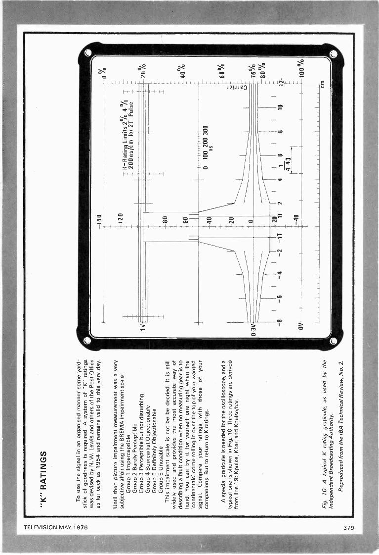
"K"
RA
TIN
GS
To
use
the
sign
al in
an
orga
nise
d m
anne
r so
me
yard
-st
ick
of g
oodn
ess
is r
equi
red.
A s
yste
m o
f "K
" ra
tings
was
dev
ised
by
N. W
. Lew
is a
nd o
ther
s of
the
Pos
t Offi
ceas
far
back
as
1954
and
rem
ains
val
id to
this
ver
y da
y.
Unt
il th
en p
ictu
re im
pairm
ent m
easu
rem
ent w
as a
ver
ysu
bjec
tive
affa
ir us
ing
the
BR
EM
A im
pairm
ent s
cale
:G
roup
1 Im
perc
eptib
leG
roup
2 B
arel
y P
erce
ptib
leG
roup
3 P
erce
ptib
le b
ut n
ot d
istu
rbin
gG
roup
4 S
omew
hat O
bjec
tiona
ble
Gro
up 5
Def
inite
ly O
bjec
tiona
ble
Gro
up 6
Unu
sabl
eT
his
impa
irmen
t sca
le is
not
be
be d
ecrie
d. It
is s
till
wid
ely
used
and
pro
vide
s th
e m
ost a
ccur
ate
way
of
desc
ribin
g a
faul
t con
ditio
n w
hen
no m
easu
ring
gear
is to
hand
. You
can
try
it fo
r yo
urse
lf on
e ni
ght w
hen
the
'con
tinen
tals
' com
e ro
lling
in o
ver
the
top
of y
our
wan
ted
sign
al.
Com
pare
you
rra
tings
with
thos
eof
your
com
pani
ons.
But
to r
etur
n to
K r
atin
gs.
A s
peci
al g
ratic
ule
is n
eede
d fo
r th
e os
cillo
scop
e, a
nd a
typi
cal o
ne is
sho
wn
in F
ig. 1
0. T
hree
rat
ings
are
der
ived
from
line
19:
Kpu
lse,
Kba
r, a
nd K
puls
e/ba
r.
Fig
.10
: A ty
pica
l K r
atin
g gr
atic
ule,
as
used
by
the
Inde
pend
ent B
road
cast
ing
Aut
horit
y.
Rep
rodu
ced
from
the
IBA
Tec
hnic
al R
evie
w, N
o. 2
.
1 V
3V -
-140
-120
K-R
atin
g Li
mits
20/
0.4
%_
200
ns/c
mfo
r 2T
Pul
se_
-60
-8-
011
-40
-20
..
I
010
0 20
0 30
0ns
000
20%
-40%
-2 -
1T1T
24
16
1.44
31
---
60%
a) - - -
76%
-80%
I
1012
-
I11
111,
1111
1111
1111
1111
11
11
II
11
I cm

co 0
"K"
RA
TIN
GS
(co
ntin
ued)
Kpu
lse
(Kp)
mea
sure
s th
e di
stor
tion
of th
e 2T
pul
sein
clud
ing
smea
rs a
nd e
choe
s. T
he 2
T p
ulse
is c
entr
ed in
the
'sub
mar
ine'
gra
ticul
e, a
djus
ted
to fi
llit,
with
its
half
ampl
itude
poi
nts
cutti
ng th
e tw
o 20
0ns
mar
kers
(F
ig.
11(a
)).
If th
e ou
tline
of t
he p
ulse
lies
with
in th
e in
ner
cont
our
of th
e gr
atic
ule
the
Kp
ratin
g is
bet
ter
than
2%
. If
the
outli
ne o
f the
pul
se li
es w
ithin
the
oute
r co
ntou
r, K
pis
bet
wee
n 2%
and
4%
. Som
e id
ea o
f how
this
affe
cts
the
pict
ure
itsel
f can
be
gain
ed b
y ap
prox
imat
ing
the
K r
atin
gto
the
BR
EM
A im
pairm
ent s
cale
. Thi
s m
eans
that
an
engi
neer
obs
ervi
ng a
pul
se o
f Kp4
% o
n th
e gr
atic
ule
wou
ld a
sses
s th
e pu
lse
resp
onse
of a
test
car
d as
gro
up4,
with
res
pect
to p
re -
shoo
ts, o
vers
hoot
s or
sm
earin
g.K
bar
(Kb)
mea
sure
s th
e til
t at t
he to
p of
the
bar.
The
bar
is la
id in
the
'goa
lpos
t' of
the
grat
icul
e so
that
the
rise
and
fall
cros
s th
e ha
lf am
plitu
de m
arke
rs, w
ith th
e to
p of
the
bar
runn
ing
cent
rally
thro
ugh
the
lines
at t
he to
p of
the
grat
ing
(Fig
. 1 1
(b)
). P
oor
I.f. r
espo
nse
will
tilt
the
bar,
but
if it
is s
trai
ght e
noug
h to
be
with
in th
e in
ner
pair
of li
nes
itra
tes
bette
r th
an K
b2%
, or
with
in th
e ou
ter
pair,
bet
ter
than
Kb4
%.
Kpu
lse/
bar(
Kp/
b) T
he a
mpl
itude
rel
atio
nshi
p be
twee
nth
e pu
lse
and
the
bar
prov
ides
a m
easu
re o
f the
ove
rall
resp
onse
of t
he s
yste
m. T
he b
ar is
set
insi
de th
e go
al -
post
as
befo
re, a
nd th
e sc
ope
trig
gere
d so
as
to d
ispl
ayth
e pu
lse
insi
de th
e su
bmar
ine
(Fig
. 11
(b)
). T
he h
eigh
t of
the
puls
e is
mea
sure
d ag
ains
t the
hei
ght o
f the
bar
, and
the
Kp/
b ra
ting
is g
iven
a n
egat
ive
valu
e if
belo
w b
arhe
ight
, pos
itive
if a
bove
.T
he s
ort o
f tol
eran
ces
expe
cted
to b
e re
alis
ed b
y th
ebr
oadc
aste
rs a
re:
Fro
m m
ain
tran
smitt
ers:
Kp
bette
r th
an 4
%, K
b be
tter
than
4%
, Kp/
b be
tter
than
4%
. Fro
m r
ebro
adca
st tr
ans-
mitt
ers:
Kp
bette
r th
an 1
1%, K
b be
tter
than
9%
, Kp/
bbe
tter
than
8%
. Mos
t bro
adca
st r
ecei
vers
are
des
igne
d to
a K
rat
ing
of b
ette
r th
an 4
%.
Impa
irmen
ts a
re (
like
lead
poi
soni
ng)
cum
ulat
ive,
so
Kra
tings
sho
uld
be a
dded
to g
ive
a to
tal i
mpa
irmen
t val
ue.
The
sum
min
g fo
llow
s a
mea
n be
twee
n lin
ear
and
squa
re -
law
, and
the
pow
er 3
/2 is
use
d.T
hus
Kto
t = K
p3'2
+ K
br +
Kp/
b3/2
.
20%
MO
D
Rat
ing
limits
-2°
/.in
ner4
%ou
ter
w
M1
77%
MO
D
8T6T
4T2T
2T4T
(a)
100%
M2
50%
CID
30%
iST
8T10
T12
T
fact
or(p
ulse
and
bar
)+
4%
2°/.
inne
rB
arR
atin
g lim
its -
4% o
uter
20°!
.M
OD
Bar
lead
ing
edge
M1
100%
2T p
ulse
-2%
-'4%
Bar
trai
ling
edge 60
%
-'MM
230
%
77%
MO
D
ST
6T41
1
2T-
2T4T
6T8T
10T
12T
(b)
1N29
7 1
Fig
. 11:
(a)
The
2T
pul
se s
ittin
g in
the
"sub
mar
ine"
par
tof
the
grat
icul
e, s
how
ing
Kp2
% (
full
line)
and
Kp4
%(b
roke
n lin
e).
(b)
The
2T
pul
se li
ned
up w
ith th
e ba
r,sh
owin
gK
p/b
-2%
.
Bla
ck P
ulse
At t
he b
ack
end
of th
e ba
r th
ere
fiequ
ently
sits
ane
gativ
e -g
oing
2T
pul
se, F
ig. 1
2. T
his
is d
ispl
ayed
on
the
osci
llosc
ope
to s
it ov
er th
e 2T
pos
itive
-go
ing
puls
e. In
theo
ry th
e tw
o sh
ould
cro
ss in
the
mid
dle,
but
in p
ract
ice
due
to q
uadr
atur
e di
stor
tion
in v
estig
ial s
ideb
and
mod
ula-
tion
they
cro
ss s
omew
here
abo
ve th
e ce
ntre
line
. The
amou
nt b
y w
hich
cro
ssov
er is
abo
ve c
entr
e be
com
es th
em
easu
re o
f qua
drat
ure
dist
ortio
n.
b
11
ab
1N29
51
Fig
. 12:
The
"bl
ack
puls
e" (
a) w
hich
is in
side
the
bar
isus
ed to
che
ck q
uadr
atur
e di
stor
tion
of th
e ve
stig
ial
side
band
net
wor
k. W
hen
lined
up
with
the
2T p
ulse
(b)
,th
e di
spla
cem
ent o
f the
cro
ssin
g po
int f
rom
the
mid
-he
ight
is a
mea
sure
of t
he d
isto
rtio
n pr
esen
t.
FU
RT
HE
R R
EA
DIN
GIf
you
are
inte
rest
ed in
taki
ng m
easu
rem
ent t
echn
ique
sfu
rthe
r w
e co
mm
end:
Tel
evis
ion
Mea
sure
men
t Tec
hniq
ues
L. E
. Wea
ver
(Pet
erP
ereg
rinus
Ltd
.), I
BA
Tec
hnic
al R
evie
w N
o 2
(IB
A),
and
the
Join
t TV
sta
ndar
ds s
peci
ficat
ion
for
625
-line
Sys
tem
-1
tran
smis
sion
s (
BB
C &
IBA
).
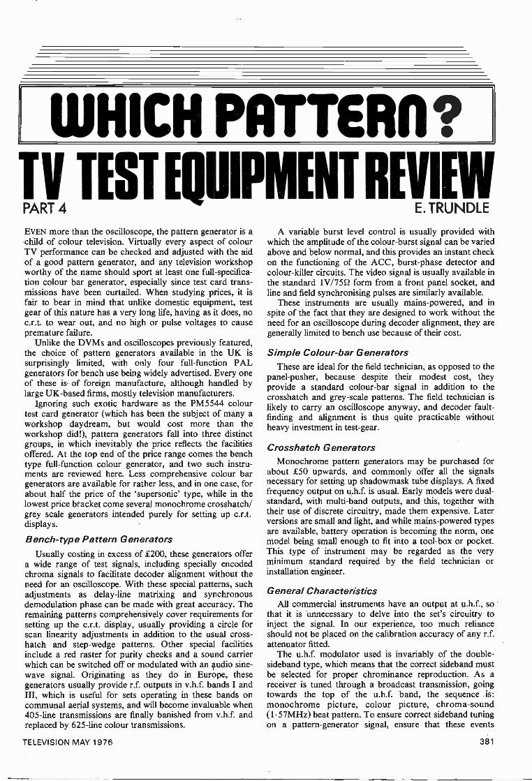
WHICH PATTER?Ty TEST EQUIPMENT REVAIL!
EVEN more than the oscilloscope, the pattern generator is achild of colour television. Virtually every aspect of colourTV performance can be checked and adjusted with the aidof a good pattern generator, and any television workshopworthy of the name should sport at least one full -specifica-tion colour bar generator, especially since test card trans-missions have been curtailed. When studying prices, it isfair to bear in mind that unlike domestic equipment, testgear of this nature has a very long life, having as it does, noc.r.t. to wear out, and no high or pulse voltages to causepremature failure.
Unlike the DVMs and oscilloscopes previously featured,the choice of pattern generators available in the UK issurprisingly limited, with only four full -function PALgenerators for bench use being widely advertised. Every oneof these is of foreign manufacture, although handled bylarge UK -based firms, mostly television manufacturers.
Ignoring such exotic hardware as the PM5544 colourtest card generator (which has been the subject of many aworkshop daydream, but would cost more than theworkshop did!), pattern generators fall into three distinctgroups, in which inevitably the price reflects the facilitiesoffered. At the top end of the price range comes the benchtype full -function colour generator, and two such instru-ments are reviewed here. Less comprehensive colour bargenerators are available for rather less, and in one case, forabout half the price of the 'supersonic' type, while in thelowest price bracket come several monochrome crosshatch/grey scale generators intended purely for setting up c.r.t.displays.
Bench -type Pattern GeneratorsUsually costing in excess of £200, these generators offer
a wide range of test signals, including specially encodedchroma signals to facilitate decoder alignment without theneed for an oscilloscope. With these special patterns, suchadjustments as delay -line matrixing and synchronousdemodulation phase can be made with great accuracy. Theremaining patterns comprehensively cover requirements forsetting up the c.r.t. display, usually providing a circle forscan linearity adjustments in addition to the usual cross-hatch and step -wedge patterns. Other special facilitiesinclude a red raster for purity checks and a sound carrierwhich can be switched off or modulated with an 4udio sine -wave signal. Originating as they do in Europe, thesegenerators usually provide r.f. outputs in v.h.f. bands I andIII, which is useful for sets operating in these bands oncommunal aerial systems, and will become invaluable when405 -line transmissions are finally banished from v.h.f. andreplaced by 625 -line colour transmissions.
A variable burst level control is usually provided withwhich the amplitude of the colour -burst signal can be variedabove and below normal, and this provides an instant checkon the functioning of the ACC, burst -phase detector andcolour -killer circuits. The video signal is usually available inthe standard 1V/7552 form from a front panel socket, andline and field synchronising pulses are similarly available.
These instruments are usually mains -powered, and inspite of the fact that they are designed to work without theneed for an oscilloscope during decoder alignment, they aregenerally limited to bench use because of their cost.
Simple Co/our-bar GeneratorsThese are ideal for the field technician, as opposed to the
panel -pusher, because despite their modest cost, theyprovide a standard colour -bar signal in addition to thecrosshatch and grey -scale patterns. The field technician islikely to carry an oscilloscope anyway, and decoder fault-finding and alignment is thus quite practicable withoutheavy investment in test -gear.
Crosshatch GeneratorsMonochrome pattern generators may be purchased for
about £50 upwards, and commonly offer all the signalsnecessary for setting up shadowmask tube displays. A fixedfrequency output on u.h.f. is usual. Early models were dual -standard, with multi -band outputs, and this, together withtheir use of discrete circuitry, made them expensive. Laterversions are small and light, and while mains -powered typesare available, battery operation is becoming the norm, onemodel being small enough to fit into a tool -box or pocket.This type of instrument may be regarded as the veryminimum standard required by the field technician orinstallation engineer.
General CharacteristicsAll commercial instruments have an output at u.h.f., so
that it is unnecessary to delve into the set's circuitry toinject the signal. In our experience, too much relianceshould not be placed on the calibration accuracy of any r.f.attenuator fitted.
The u.h.f. modulator used is invariably of the double-sideband type, which means that the correct sideband mustbe selected for proper chrominance reproduction. As areceiver is tuned through a broadcast transmission, goingtowards the top of the u.h.f. band, the sequence is:monochrome picture, colour picture, chroma-sound(1.57MHz) beat pattern. To ensure correct sideband tuningon a pattern -generator signal, ensure that these events
TELEVISION MAY 1976 381
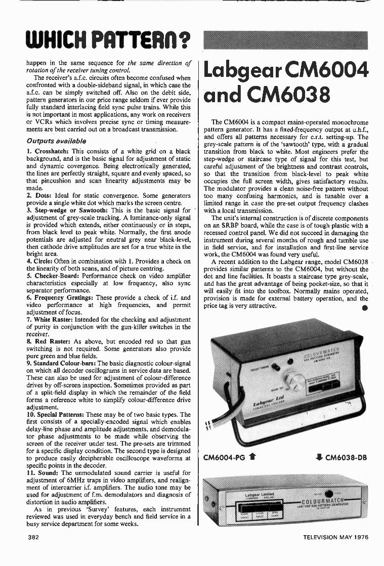
WHICH PATTER11?happen in the same sequence for the same direction ofrotation of the receiver tuning control.
The receiver's a.f.c. circuits often become confused whenconfronted with a double-sideband signal, in which case thea.f.c. can be simply switched off. Also on the debit side,pattern generators in our price range seldom if ever providefully standard interlacing field sync pulse trains. While thisis not important in most applications, any work on receiversor VCRs which involves precise sync or timing measure-ments are best carried out on a broadcast transmission.
Outputs available1. Crosshatch: This consists of a white grid on a blackbackground, and is the basic signal for adjustment of staticand dynamic covergence. Being electronically generated,the lines are perfectly straight, square and evenly spaced, sothat pincushion and scan linearity adjustments may bemade.2. Dots: Ideal for static convergence. Some generatorsprovide a single white dot which marks the screen centre.3. Step -wedge or Sawtooth: This is the basic signal foradjustment of grey -scale tracking. A luminance -only signalis provided which extends, either continuously or in steps,from black level to peak white. Normally, the first anodepotentials are adjusted for neutral grey near black -level,then cathode drive amplitudes are set for a true white in thebright area.4. Circle: Often in combination with 1. Provides a check onthe linearity of both scans, and of picture centring.5. Checker -Board: Performance check on video amplifiercharacteristics especially at low frequency, also syncseparator performance.6. Frequency Gratings: These provide a check of i.f. andvideo performance at high frequencies, and permitadjustment of focus.7. White Raster: Intended for the checking and adjustmentof purity in conjunction with the gun -killer switches in thereceiver.& Red Raster: As above, but encoded red so that gunswitching is not required. Some generators also providepure green and blue fields.9. Standard Colour -bars: The basic diagnostic colour -signalon which all decoder oscillograms in service data are based.These can also be used for adjustment of colour -differencedrives by off -screen inspection. Sometimes provided as partof a split -field display in which the remainder of the fieldforms a reference white to simplify colour -difference driveadjustment.10. Special Patterns: These may be of two basic types. Thefirst consists of a specially -encoded signal which enablesdelay -line phase and amplitude adjustments, and demodula-tor phase adjustments to be made while observing thescreen of the receiver under test. The pre-sets are trimmedfor a specific display condition. The second type is designedto produce easily decipherable oscilloscope waveforms atspecific points in the decoder.11. Sound: The unmodulated sound carrier is useful foradjustment of 6MHz traps in video amplifiers, and realign-ment of intercarrier i.f. amplifiers. The audio tone may beused for adjustment of f.m. demodulators and diagnosis ofdistortion in audio amplifiers.
As in previous 'Survey' features, each instrumentreviewed was used in everyday bench and field service in abusy service department for some weeks.
Labgear CM6004and CM6038
The CM6004 is a compact mains -operated monochromepattern generator. It has a fixed -frequency output at u.h.f.,and offers all patterns necessary for c.r.t. setting -up. Thegrey -scale pattern is of the `sawtooth' type, with a gradualtransition from black to white. Most engineers prefer thestep -wedge or staircase type of signal for this test, butcareful adjustment of the brightness and contrast controls,so that the transition from black -level to peak whiteoccupies the full screen width, gives satisfactory results.The modulator provides a clean noise -free pattern withouttoo many confusing harmonics, and is tunable over alimited range in case the pre-set output frequency clasheswith a local transmission.
The unit's internal construction is of discrete componentson an SRBP board, while the case is of tough plastic with arecessed control panel. We did not succeed in damaging theinstrument during several months of rough and tumble usein field service, and for installation and first -line servicework, the CM6004 was found very useful.
A recent addition to the Labgear range, model CM6038provides similar patterns to the CM6004, but without thedot and line facilities. It boasts a staircase type grey -scale,and has the great advantage of being pocket-size, so that itwill easily fit into the toolbox. Normally mains operated,provision is made for external battery operation, and theprice tag is very attractive.
CM6004-PG 4 CM6038-DB
COLOURNIATCHUHF,' VHF 625 PAZIng GENERATOR
382 TELEVISION MAY 1976
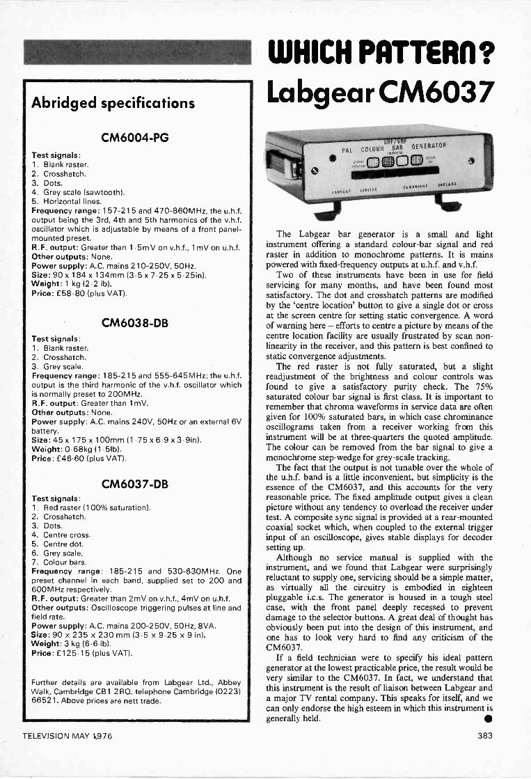
Abridged specifications
CM6004-PGTest signals:1. Blank raster.2. Crosshatch.3. Dots.4. Grey scale (sawtooth).5. Horizontal lines.Frequency range: 157-215 and 470-860MHz, the u.h.f.output being the 3rd, 4th and 5th harmonics of the v.h.f.oscillator which is adjustable by means of a front panel -mounted preset.R.F. output: Greater than 1 .5m V on v.h.f., 1 mV on u.h.f.Other outputs: None.Power supply: A.C. mains 210-250V, 50Hz.Size: 90 x 184 x 134mm (3.5 x 7.25 x 5.25in).Weight: 1 kg (2.2 lb).Price: £58.80 (plus VAT).
CM6038-DBTest signals:1. Blank raster.2. Crosshatch.3. Grey scale.Frequency range: 185-215 and 555-645MHz; the u.h.f.output is the third harmonic of the v.h.f. oscillator whichis normally preset to 200MHz.R.F. output: Greater than 1 mV.Other outputs: None.Power supply: A.C. mains 240V, 50Hz or an external 6Vbattery.Size: 45 x 175 x 100mm (1.75 x 6.9 x 3.9in).Weight: 0.68kg (1 .51b).Price: £46.60 (plus VAT).
CM6037-DBTest signals:1. Red raster (100% saturation).2. Crosshatch.3. Dots.4. Centre cross.5. Centre dot.6. Grey scale.7. Colour bars.Frequency range: 185-215 and 530-630MHz. Onepreset channel in each band, supplied set to 200 and600MHz respectively.R.F. output: Greater than 2mV on v.h.f., 4mV on u.h.f.Other outputs: Oscilloscope triggering pulses at line andfield rate.Power supply: A.C. mains 200-250V, 50Hz, 8VA.Size: 90 x 235 x 230 mm (3.5 x 9.25 x 9 in).Weight: 3 kg (6.6 lb).Price: £125.15 (plus VAT).
Further details are available from Labgear Ltd., AbbeyWalk, Cambridge CB1 2RQ, telephone Cambridge (0223)66521. Above prices are nett trade.
WHICH PATTERI1?
Labgear CM6037
PAL COLOUR BAR GENERATOR
00
The Labgear bar generator is a small and lightinstrument offering a standard colour -bar signal and redraster in addition to monochrome patterns. It is mainspowered with fixed -frequency outputs at u.h.f. and v.h.f.
Two of these instruments have been in use for fieldservicing for many months, and have been found mostsatisfactory. The dot and crosshatch patterns are modifiedby the 'centre location' button to give a single dot or crossat the screen centre for setting static convergence. A wordof warning here - efforts to centre a picture by means of thecentre location facility are usually frustrated by scan non -linearity in the receiver, and this pattern is best confined tostatic convergence adjustments.
The red raster is not fully saturated, but a slightreadjustment of the brightness and colour controls wasfound to give a satisfactory purity check. The 75%saturated colour bar signal is first class. It is important toremember that chroma waveforms in service data are oftengiven for 100% saturated bars, in which case chrominanceoscillograms taken from a receiver working from thisinstrument will be at three-quarters the quoted amplitude.The colour can be removed from the bar signal to give amonochrome step -wedge for grey -scale tracking.
The fact that the output is not tunable over the whole ofthe u.h.f. band is a little inconvenient, but simplicity is theessence of the CM6037, and this accounts for the veryreasonable price. The fixed amplitude output gives a cleanpicture without any tendency to overload the receiver undertest. A composite sync signal is provided at a rear -mountedcoaxial socket which, when coupled to the external triggerinput of an oscilloscope, gives stable displays for decodersetting up.
Although no service manual is supplied with theinstrument, and we found that Labgear were surprisinglyreluctant to supply one, servicing should be a simple matter,as virtually all the circuitry is embodied in eighteenpluggable i.c.s. The generator is housed in a tough steelcase, with the front panel deeply recessed to preventdamage to the selector buttons. A great deal of thought hasobviously been put into the design of this instrument, andone has to look very hard to find any criticism of theCM6037.
If a field technician were to specify his ideal patterngenerator at the lowest practicable price, the result would bevery similar to the CM6037. In fact, we understand thatthis instrument is the result of liaison between Labgear anda major TV rental company. This speaks for itself, and wecan only endorse the high esteem in which this instrument isgenerally held.
TELEVISION MAY 1976 383
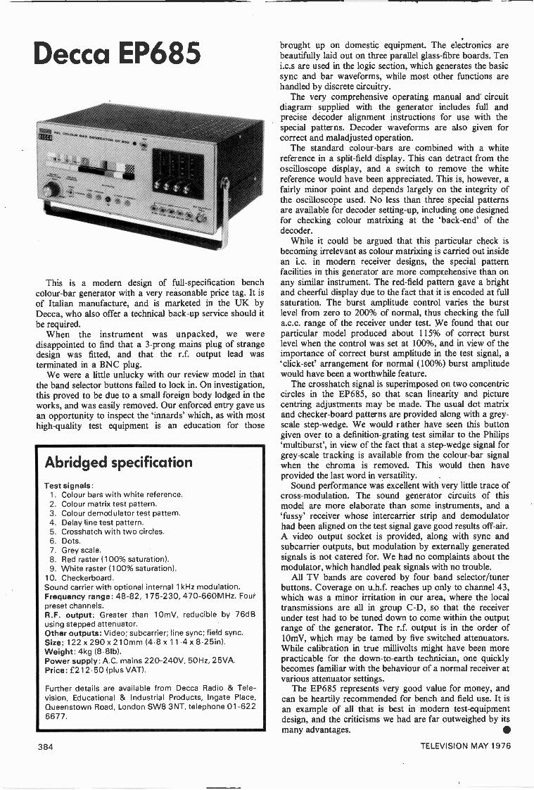
Decca EP685
This is a modern design of full -specification benchcolour -bar generator with a very reasonable price tag. It isof Italian manufacture, and is marketed in the UK byDecca, who also offer a technical back-up service should itbe required.
When the instrument was unpacked, we weredisappointed to find that a 3 -prong mains plug of strangedesign was fitted, and that the r.f. output lead wasterminated in a BNC plug.
We were a little unlucky with our review model in thatthe band selector buttons failed to lock in. On investigation,this proved to be due to a small foreign body lodged in theworks, and was easily removed. Our enforced entry gave usan opportunity to inspect the 'innards' which, as with mosthigh -quality test equipment is an education for those
Abridged specificationTest signals:
1. Colour bars with white reference.2. Colour matrix test pattern.3. Colour demodulator test pattern.4. Delay line test pattern.5. Crosshatch with two circles.6. Dots.7. Grey scale.8. Red raster (100% saturation).9. White raster (100% saturation).
10. Checkerboard.Sound carrier with optional internal 1 kHz modulation.Frequency range: 48-82, 175-230, 470-660MHz. Fourpreset channels.R.F. output: Greater than 10mV, reducible by 76dBusing stepped attenuator.Other outputs: Video; subcarrier; line sync; field sync.Size: 122 x 290 x 210mm (4.8 x 11.4 x 8.25in).Weight: 4kg (8-81b).Power supply: A.C. mains 220-240V, 50Hz, 25VA.Price: £212.50 (plus VAT).
Further details are available from Decca Radio & Tele-vision, Educational & Industrial Products, Ingate Place,Queenstown Road, London SW8 3NT, telephone 01-6226677.
brought up on domestic equipment. The electronics arebeautifully laid out on three parallel glass -fibre boards. Teni.c.s are used in the logic section, which generates the basicsync and bar waveforms, while most other functions arehandled by discrete circuitry.
The very comprehensive operating manual and circuitdiagram supplied with the generator includes full andprecise decoder alignment instructions for use with thespecial patterns. Decoder waveforms are also given forcorrect and maladjusted operation.
The standard colour -bars are combined with a whitereference in a split -field display. This can detract from theoscilloscope display, and a switch to remove the whitereference would have been appreciated. This is, however, afairly minor point and depends largely on the integrity ofthe oscilloscope used. No less than three special patternsare available for decoder setting -up, including one designedfor checking colour matrixing at the 'back -end' of thedecoder.
While it could be argued that this particular check isbecoming irrelevant as colour matrixing is carried out insidean i.c. in modern receiver designs, the special patternfacilities in this generator are more comprehensive than onany similar instrument. The red -field pattern gave a brightand cheerful display due to the fact that it is encoded at fullsaturation. The burst amplitude control varies the burstlevel from zero to 200% of normal, thus checking the fulla.c.c. range of the receiver under test. We found that ourparticular model produced about 115% of correct burstlevel when the control was set at 100%, and in view of theimportance of correct burst amplitude in the test signal, a`click -see arrangement for normal (100%) burst amplitudewould have been a worthwhile feature.
The crosshatch signal is superimposed on two concentriccircles in the EP685, so that scan linearity and picturecentring adjustments may be made. The usual dot matrixand checker -board patterns are provided along with a grey -scale step -wedge. We would rather have seen this buttongiven over to a definition -grating test similar to the Philips`multibursf, in view of the fact that a step -wedge signal forgrey -scale tracking is available from the colour -bar signalwhen the chroma is removed. This would then haveprovided the last word in versatility.
Sound performance was excellent with very little trace ofcross -modulation. The sound generator circuits of thismodel are more elaborate than some instruments, and a`fussy' receiver whose intercarrier strip and demodulatorhad been aligned on the test signal gave good results off -air.A video output socket is provided, along with sync andsubcarrier outputs, but modulation by externally generatedsignals is not catered for. We had no complaints about themodulator, which handled peak signals with no trouble.
All TV bands are covered by four band selector/tunerbuttons. Coverage on u.h.f. reaches up only to channel 43,which was a minor irritation in our area, where the localtransmissions are all in group C -D, so that the receiverunder test had to be tuned down to come within the outputrange of the generator. The r.f. output is in the order of10mV, which may be tamed by five switched attenuators.While calibration in true millivolts might have been morepracticable for the down-to-earth technician, one quicklybecomes familiar with the behaviour of a normal receiver atvarious attenuator settings.
The EP685 represents very good value for money, andcan be heartily recommended for bench and field use. It isan example of all that is best in modern test -equipmentdesign, and the criticisms we had are far outweighed by itsmany advantages.
384 TELEVISION MAY 1976

111,111111111111111111 WHICH PATTERn?
This is a full -specification pattern generator with allfacilities. It is rather expensive by comparison with similargenerators by other manufacturers, but offers full coverageof the u.h.f. band and a useful VCR test pattern.
As the specification shows, ten patterns are offered, fivein monochrome and five in colour. The `demod' pattern isused for alignment of three decoder functions, and thestandard colour -bars form part of a split -field display withthe bottom third of the screen as a white reference. It ispossible to extend the colour -bars to fill the whole screen bymeans of an internal link, and we fitted a switch so that thiscould be done at will. The red raster provides a ratherwashed-out red field due to the fact that it is at 50%saturation, and we were happier to use the white raster inconjunction with the gun switches when setting purity.
The VCR test pattern consists of a chrominancedefinition grating extending from 100kHz to 1MHz with an8 -step wedge of increasing saturation. Apart from itsintended function, this was found useful during experi-mental decoder work, during which the signal was takenfrom the video output socket.
Unusually, the chroma amplitude control adjusts thelevel of burst and chrominance signals together, so that ifthe a.c.c. in a receiver is functioning correctly, the satura-tion should remain reasonably constant over most of therange of this control.
Turning to the monochrome patterns, the `multiburst' asPhilips call it was found most useful, offering a check onbandwidth and definition. This feature was absent from theother instruments we tested. By pressing both the relevantbuttons, the electronic circle can be superimposed on thecrosshatch pattern to form a composite pattern which maybe used to centre a picture in the absence of a broadcast testcard.
The sound facility on the PM5509 was not the best of thegenerators we reviewed, being marred by vision on soundeffects depending on the pattern in use. Both sound andvision may be fed into the generator from external sourcesto be modulated onto a u.h.f. carrier, and this is a valuablepoint. Outputs at r.f. are available in all TV bands, beingselected by five push -buttons with corresponding tuningpotentiometers. The range and frequency are displayed ontwo illuminated meters, a seemingly unnecessary refinementwhich must contribute to the final cost of the instrument.
The u.h.f. modulator in our review instrument tended tooverload on peak white and peak chroma leading to signalcrushing. This, in all fairness, may have been a quirk ormaladjustment of this particular instrument, and if so, couldaccount for the cross -modulation on sound referred toearlier. A calibrated r.f. attenuator is provided, but it wasfound that when the attenuator was set to 1 mV, thedisplayed pattern was very much more grainy than with ameasured 1 mV off -air signal.
Front panel sockets provide line and field trigger pulses,video in/out and r.f. output. The video output socketprovides a composite video chroma and sync signal atabout a volt peak to peak - this is similar to the signalobtainable from a conventional video detector, and as suchcan be very useful. Another bonus point with this instru-ment is that the Band I coverage extends down to thestandard vision i.f. frequency, so that signals can be injectedinto an i.f. strip direct.
Philips PM5509
The PM5509 is a most desirable instrument, and itshighish price is offset by the many facilities it offers. Whileit is eminently suitable for general workshop use, it isparticularly recommended where a wide range of equipmentis serviced, and lends itself well to experimental work on alltypes of TV equipment.
Abridged specificationTest signals:
1. Checkerboard.2. Circle.3. Crosshatch.4. Dots.5. Grey scale with definition lines 0.5 - 5MHz
rmultiburst"").6. Red raster (50% saturation.7. White raster (100% saturation) with colour burst.8. Delay line/demodulator test pattern.9. Colour bars with white reference.
10. VCR test pattern.Sound carrier with internal/external modulation.Frequency range: 38-85, 170-250, 470-790MHz.Five preset channels.R.F. output: Greater than 10mV, reducible by 60dBusing the continuously variable attenuator.Other outputs: Video; Sync; VCR.Power supply: A.C. mains 115 or 230V ±15%, 50-60Hz, 16VA.Size: 195 x 235 x 270mm (7.7 x 9.25 x 10.6in).Weight: 3.7kg (8.21b).Price: £350.00 (plus VAT).Further details are available from Pye Unicam Ltd., PhilipsElectronic Instruments Dept., York Street, CambridgeCB1 2PX, telephone Cambridge (0223) 58866.
TELEVISION MAY 1976 385
Yo
urPROBLEMSsolved
Requests for advice in de'aling with servicing problems must beaccompanied by an 11 p postal order (made out to I PC Magazines Ltd.), thequery coupon from page 387 and a stamped addressed envelope. We candeal with only one query at a time. We regret that we cannot supply servicesheets nor answer queries over the telephone.
DECCA CS2213This receiver has always tended to lack saturation, i.e. thecolour intensity control is permanently flat out and onlymarginally achieves sufficient saturation. The decoder hasbeen carefully realigned in accordance with the procedureset out in the official service manual, but with littleimprovement.
Low saturation in this chassis can be due to a faultycolour -killer transistor (TR214) or a leaky or low -valuesaturated during a colour transmission. Possible faults hereare inadequate output from the ident stage, defectivecolour -killer transistor (TR214) or a leaky or low -valuebase bias electrolytic C236. Deterioration of theelectrolytic C230 which decouples the emitter of the secondchrominance amplifier transistor TR212 is anotherpossibility. For correct chrominance gain the base currentof the first chrominance amplifier transistor TR210 iscritical: check whether its base bias resistor R248 (180k52)has changed value. (Decca series 10 chassis.)
NATIONAL PANASONIC TC85HAThe problem with this Japanese colour receiver is atendency for the picture to change to complementarycolours, i.e. green faces.
Unlike many Japanese sets, National Panasonic modelsall use standard PAL decoding techniques. The bistableswitching circuit is falling out of synchronisation due tolack of output from the ident circuit. Simply tweaking theident coil L610 for maximum output should put mattersright. If not you will have to check back through TR602and TR605 to the reference signal i.c. IC602 to find outwhy the ident signal amplitude is low.
GRANADA 916/2This v.h.f. only mains portable set looks like a Thornchassis, but I've been unable to track down the correctchassis type number. The problem is field slip as the setwarms up. Adjusting the field hold control or turning up thecontrast corrects the slip for a while: if the controls are nottouched at all the slip gets faster until a white line acrossthe centre of the screen appears, about twice a second. Ifthe field is relocked the raster is perfectly linear. The EF80video and sync separator valves and the 30PL14 fieldtimebase valve have been replaced without making anyimprovement.
The set is fitted with the Thorn 980 chassis as used inseveral Ferguson, HMV and Ultra models. When servicingone of these the condition of the resistors associated withthe video amplifier EF80, in particular the 10kS2 anode loadresistor R27 to the left and the 39k52 bias stabilisingresistor R26 which is behind, should always be checked.The present trouble is more likely to be due to a componentfault in the field timebase however. Check the componentsassociated with the pentode anode (pin 6)/triode grid (pin1) circuit of the 30PL14. These are C54 (0.01µF), R71(681a2), R72 (68kS2) and the hold control itself which wehave known to be responsible for the fault.
ALBA TC2222After about two hours' operation there is slight pictureblurring which then slowly increases. Whether the picture isbright or dim does not affect the fault. A new e.h.t. triplerhas made no difference.
This fault is often due to a minute discharge across thespark gap associated with the focus pin (9) of the c.r.t.Clean up in this area, and slightly enlarge the gap with afile. If the fault persists, replace the focus control assembly.(Thorn 3000 chassis.)
ITT CK651The fault usually appears after the set has been on forabout two hours, and takes the form of a patch ofyellowish -green lines superimposed on the raster in thelower left-hand section of the screen. The lines show upmost vividly against a plain red background, and vanishwhen the picture is black or white. On a plain bluebackground they change colour to purple. The lines seemto be on alternate scan lines. The right-hand vertical edge ofthe patch is fairly well defined and is always in the sameposition, about a third of the way across the screen. Theheight of the patch varies erratically however. Increasingthe contrast control setting reduces the height of the patch.
Check the phasing of the subcarrier traps L71 and L72- the direction of the windings should be clockwise whenviewed from above. Check the 8µF decouplers C219 andC152 on the decoder board. Ensure that the leads to theconvergence box are dressed tight against the degaussingshield. If necessary replace the speed-up capacitors C220and C225 in the bistable circuit with 68pF ceramic ones.(ITT CVC8 chassis.)
386 TELEVISION MAY 1976
BUSH CTV184STo start with there was no blue picture content. This wascorrected by fitting a new blue output transistor.Following this however there are horizontal lines, spacedapproximately an inch apart but closer at the top of thescreen. They show up as blue behind a blue scene andyellow on lighter shades. At times the lines are not visible:also they are stationary, i.e. moving neither up nor downthe screen. None of the customer controls has any effect onthe lines. The decoder panel fitted is the later two i.c. type.
The problem is almost certainly coming from the bluechannel, around transistors 3VT6/3VT9. Check the newoutput transistor by substitution, then check the BC148driver transistor, the ITT2002 (3D7) blue clamp diode andthe input coupling capacitor 3C44 (64µF). The point can
be proved by swapping over the blue and red cathode feedsto the c.r.t., whereupon the fault should appear in red/cyaninstead of blue/yellow. (RRI A823A chassis.)1111111.11111111111111111111111111111111111
QUERY COUPONAvailable until 17 May 1976. One coupon,plus an 1 1 p (inc. VAT) postal ordermust accompany EACH PROBLEM sent inaccordance with the notice on page 386.
TELEVISION MAY 1976Illissamansaumaimmaaammull
161Each month we provide an interesting case of television
servicing to exercise your ingenuity. These are not trickquestions but are based on actual practical faults.
Elongated heads and crushed captions was the fault presenton a Murphy Model V153 U. The fault was examined firstby the field technician, who reported that field linearitycontrol adjustment and valve substitution made nodfference.
In the workshop a test pattern display certainly revealedrather bad vertical non -linearity, and while the top fieldlinearity control 3R V7 modified the non -linearity thecontrol arrived at the end of its range before correction wascomplete. As similar symptoms had been encountered due toa low -emission PCL85 field timebase valve it was decided tonote the change in non -linearity after replacing this.
The replacement valve gave a marked improvement in thelinearity, which could then be almost competely cured byadjusting the linearity controls. On inspection, the output
stage cathode components appeared to be in good condition.At this stage it was noticed that the field lock was belowpar; also that as the receiver increased in temperature, sothe vertical linearity became worse.
On changing back to the original valve it was noticedthat the replacement had been running at a higher tempera-ture than normal for this circuit.
One or two resistors associated with the field hold andlinearity controls had changed value and were replaced, butwith only minimal effect on the results obtained. The circuitwas then examined in greater detail, and with an AvoModel 8 connected across one component in the linearitycorrection feedback circuit the symptom became very muchworse. This gave the technician the clue to the cause of thetrouble. The component was replaced and perfect linearityand improved locking were then achieved.
What was the most likely component at fault? See nextmonth's Television for the solution and for another item inthe Test Case series.
SOLUTION TO TEST CASE 160(Page 331 last month)
The clue to the problem was the rain storm! Althoughthis was not immediately obvious to us - or indeed themechanism responsible - it nevertheless became apparentthat wet weather had a significant bearing on thesymptom.
After the storm the aerial was examined for ingress ofmoisture at the point of feeder connection, but all was bonedry here. It took several calls and much head scratching tocome up with the answer. Since the aerial was mountedfairly close to the sloping roof, the distance between thedipole and the slates was critical with respect to the wave-length of the channel affected. Under wet conditions theroof tended to act as a relatively efficient signal reflector,and on the channel affected the distance was just right foralmost complete cancellation of the direct signal picked upby the aerial!
The aerial was raised in order to decrease the anglerelative to the roof, and this completely cured the trouble.Since this event a second case with virtually identicalfactors has been cleared in the same way.
Published on approximately the 22nd of each month by IPC Magazines Limited, Fleetway House, Farringdon Street, London EC4A 4AD. Filmsetting byPacesetters, London SE1. Printed in England by Carlisle Web Offset, Newtown Trading Estate, Carlisle. Sole Agents for Australia and New Zealand - Gordonand Gotch (Aisle) Ltd.; South Africa - Central News Agency Ltd. "Television" is sold subject to the following conditions, namely that it shall not, withoutthe written consent of the Publishers first having been given, be lent, resold, hired out or otherwise disposed of by way of Trade at more than therecommended selling price shown on the cover, excluding Eire where the selling price is subject to VAT, and that it shall not be lent, resold, hired out orotherwise disposed of in a multilated condition or in any unauthorised cover by way of Trade or affixed to or as part of any publication or advertising,literary or pictorial matter whatsoever.
TELEVISION MAY 1976 387

TELEVISION CLASSIFIED ADVERTISEMENTSThe pre -paid rate for classified advertisements is 10p a word (minimum 12 words), box number 35p extra. Semi -displaysetting £5.50 per single column inch. All cheques, postal orders, etc., to be made payable to TELEVISION and crossed"Lloyds Bank Ltd." Treasury notes should always be sent registered post. Advertisements, together with remittance, shouldbe sent to the GMG, Room 2337, Classified Advertisement Manager, TELEVISION IPC Magazines Ltd., King's ReachTower, Stamford Street, London SE I 9LS, for insertion in the next available issue. (01-261 5846).
SETS & COMPONENTS
VALVE LISTALL VALVES FULLY TESTED
Five valves or over postage paidUnder five valves postage 6p each
DY86/8 7 ISpi PC900 BpPCL85/805 20pp PCC84 Bp PL36 20p
ECC82 10P PCC85 209 PL5 25pECL80 8P PCC89 8p PY302/4 33 15pEF80 8p PCC 189 8p PY81/800 15pEF85 8p PCC805 15p PY801 20pEF183 10p PCF80 8p UI91 15pEF184 10P PCF86 ISp 6F23 15pEH90 13P PCF805 20p 6/30L2 15p
EY86/87 13p PCL82 ISp 30F5 10pPC86 ISp PCL83 ISp 30FLI 20pPC88 15p PCL84
AND MANY MORE AVAILABLE15p
S. W. ELECTRONICS114 Burnley Road. Rawtenstall. Rossendale, Lancs.
COLOUR T.V. (EX. RENTAL)IN WORKING ORDER
19" screen - £85.00 + £5.50 Post, Packing25" screen - £95.00 & InsuranceMakes available, GEC, Bush. Deceit, Thorn 2000, Baird, Philips.Mail Order Only. Cash or Cheque with Order. Regret no personalcallers. Please allow 14 days for delivery.Any enquiries with SAE please, to:
"WESTRONICS"15 CROSS GREEN LANE, HALTON, LEEDS 15 LS15 7SR.
TURN YOUR SURPLUS capacitors, transistors.etc., into cash. Contact Coles -Harding & Co..P.O. Box 5. Frome, Somerset. Immediate cashsettlement.
INTEGRATED CIRCUITS
TBA 530 QTBA 540 QTBA 550 Q
£2.853.254.20
740074137474
£0.18.35.38
TBA 560 CQ 4.00 7490 .38TBA 750 Q 2.15 CD4022A 1.58TBA 990 Q 4.32 555 .52TBA 810 S 1.25 MC1310 2.50TC A 270 SQ 3.90 741 .350 lmfd poly .06 RedLEDS .32
Full range of 74 series available. WW Teletext ICs in stock.
Enquiries and latest lists send SAE.
ALL PRICES INCLUDE VAT (P&P add 10P)
MAIL ORDER TO: KENWARD ELECTRONICS,151 Western Avenue, Bournemouth BH 10 6HQ.
CALLERS ONLY AT: 59 Seabourne Road.
MAINS DROPPERS37-31-97-26-16852 50p.25-35-97-59-3012 50p14-26-97-16012 50p.14-26-97-17352 50p.1519-20-70-63-28-6352 50p.
Post free. C.W.O.Durham Supplies
367 Kensington Street, Bradford, 8, Yorkshire
250 New Resistors, well assorted. Watts.Carbon -Hi -Stab Oxide, etc. £1.50 post free.Whitsam Electrical, 33 Drayton Green RoadLondon, W 13.
ELECTRONICALLY TESTED TV VALVESDY86/7 15pECC82 ISpEF183 ISpEF184 15pPC86 ISp
PC88 15pPC97 15pPCF802 15pPCL82 10pPCL84 10p
PCL86PCL805/85PL50430PLI
15p20p20p15p
COLOUR TYPESPL508 30p PL509 40p PY500/A 35p
Many others available, please send list of types requiredwith s.a.e. for quotation. AU valves subject to availability.
P. & P. 7p per valve. Orders over £6 post free.Mail order only.
L. & D. COMPONENTS LTD.71 WESTBURY AVE., LONDON N22 6SA
TECHNALOGICSannounce the logical choice for setting up
COLOUR T.V. RECEIVERS:
PATTERN GENERATOR MODEL PG3
This compact unit generates SIX invaluable videopatterns at the turn of a switch.
*CROSSHATCH GRID01:IT MATRIX*VERTICALS*HORIZONTALS*WHITE RASTER
Advanced circuitry onGlass Fibre P.C.B. Housedin TOUGH CASE 5" x 4" a 2"(approx.). Low consumptionfrom standard 9V binaries
GBEYSCALE (STEPWEDGE) (not supplied).
Use when adjusting: Static Convergence, DynamicConvergence, Picture Geometry, Colour Purity, Focus,Beam Limiting, Grey -Scale Tracking, Black -levelClamping, etc. etc. Single direct connection to set;large output for valve or solid state sets. Available asa kit plus instructions £11.75, or built and tested£14.75, inclusive. Mail Order from
TECHNALOGICS,8 EGERTON STREET, LIVERPOOL, L8 7 LY.
MERSEYSIDE.Enquiries SAE please.
500 COMPONENTS. Resistors, Capacitors, Diodes,Transistors, Pots, Coils, etc. Identified, formedleads, fall -out, and surplus. Good value at £1.60. Allinclusive (U.K. postal rates only). CWO please toL. PENSENEY, T Bankhead Farm, South Queens -ferry, West Lothian.
VALVE BARGAINSANY 1-12p, 5-50p, 10-90p, 50-010
ECC82, ECH84, EH90. DY86/7, EF80, EF183,EF184, PC86, PC88, PCF80, PCF802, PCL82,PCL84. PCL85/805, PCL86. PY81, PY800,PY88, PL36, PL504, 6F28, 30PL14.
COLOUR VALVES 25p EACH
PY500/A, PL508, PL509.
Postage & Packing 20p, no VAT.
VELCO ELECTRONICS9 Mandeville Terrace, Hawkshaw, Via Bury, Lancs.
EX RENTALTV's BARGAIN
23" & 19" 3 Channel with U.H.F. Tuner £3.5019" & 25" Colour from £50.0019" & 23" tubes guaranteed from £2.00
All sets complete.EDWARDS & SONS
103 Goldhawk Road, London, W.12.Telephone: 743 6996.
CALLERS ONLY
BRC 2000, 3000, 3500, 8000, 8500Phillips G8
Panel Repair/Exchange Singles or Bulk
MODULAR ELECTRONICS160 Brabazon Road, Hounslow TW5 9LP
Tel. 01-897 0976
REPAIRS
TUBE POLISHING your valuable colour tubes can,in most cases, be ground and polished as new for only£4. Standard charge £6.56. Return, carriage and VATpaid. CWO. Retube Limited, North Somercotes,Louth, Lincs. Phone: N/S 300 STD (050785).
EDUCATIONAL
C AND G EXAMSMake sure you succeed with an ICS home study coursefor C and G Electrical Installation Work andTechnicians, Radio/TV/ Electronics Technicians.Telecomms Technicians and Radio Amateurs.
COLOUR TV SERVICINGMake the most of the current boom! Learn thetechniques of servicing Colour and Mono TV setsthrough new home study courses, approved by leadingmanufacturers.
TECHNICAL TRAININGHome study courses in Electronics and ElectricalEngineering. Maintenance, Radio, TV, Audio, ComputerEngineering and Programming. Also self -build radio kits.Get the qualifications you need to succeed.
Free details from:INTERNATIONAL
CORRESPONDENCE SCHOOLSDept 8015. Intertext House, London SW8 4UJ
Or Phone 01-622 9911 (All Hours/
TELEVISIONTRAINING
16 MONTHS' full-time practical andtheoretical training course in Radio & TVServicing (Mono & Colour) for beginnerswith GCE (or equivalent) in Maths. andEnglish.
13 WEEKS' full-time Colour TV Servicingcourse. Includes 100 hours practicaltraining. Mono revision if necessary. Goodelectronics background essential.
NEXT SESSION commences on April 20th.
PROSPECTUS FROM:London Electronics College, Dept. TT5,20 Penywern Road, London SW5 9SU.Tel. 01-373 8721.
TAPETALKSThe CLEVER war to LEARN.
TWO C60 Cassettes entitled"BASIC TV PRINCIPLES"
£5.44 plus 55p VAT/P&P
TAPETALKP.O. Box 99(E),
Milton Keynes MK3 5BR.Tel: Milton Keynes (0908) 77710.
FOR SALE
LABGEAR Televerta (VHF/UHF Converter) inperfect working order. £14 o.n.o. Phone 01-903 2356.
TELEVISION 22" Colour Receiver, nearly completeincluding tube, carefully constructed, aligned, maga-zines, offers. Orpington 29025.
BRC 2000 Colour, complete set spare panels, someworking. £50. Harber, Chard (04606) 2240.
FOR SALE: "TELEVISION" Football Game, built,working perfect at cost of parts £50.00. W. Ferguson,Henshaw, Hexham, Northumberland. Bardon Mill407.
FOR SALE: COLOUR TV 19" GEC 2028. TradeOnly. Requires Overhaul. Tel: Ampthill 403466(Ansafone).
FORGESTONE 400 Colour receiver. Tuner, I.F.and Decoder for sale, in original kit form asreceived from Forgestone, untouched, cost £60accept £40. Apply Box No. 129.
TELEVISION COLOUR RECEIVER. Constructorhas most boards, etc., professionally built but neverinterwired (no tube or scan coils) for sale at approx.half the cost of the components alone. NO V.A.T.S.a.e. for list to: D. M. NICHOLLS, "Brooklyn",Shore Road, Gronant, Prestatyn, Clwyd.
388 TELEVISION MAY 1976

SERVICE SHEETS
SERVICE SHEETS. SERVICE MANUALSPRACTICAL AND TECHNICAL BOOKS
COVERING COLOUR & MONO TELEVISIONS, RADIOS, RECORD PLAYERS, TAPE RECORDERS, ETC.
SERVICE SHEETS 50p PLUS SA.E. SERVICE SHEET CATALOGUE 25p
BOOKS COLOUR TV MANUALSPRICES INCLUDE POSTAGE U.K. ONLY
SERVICING WITH THE OSCILLOSCOPE 2nd EDN. by G. J. King £4.80TV FAULT FINDING BOOK by Data Publications Ltd £1.15COLOUR TELEVISION THEORY by G. H. Hutson £5.50COLOUR TELEVISION PICTURE FAULTS by K. J. Bohlman £2.70COLOUR TELEVISION SERVICING by G. J. King £5.90FIRST BOOK OF DIODE EQUIVALENTS by B. B. Babani £1.10SECOND BOOK OF TRANSISTOR EQUIVALENTS by B. B. Babani £1.15HANDBOOK OF I. C. EQUIVALENTS by B. B. Babani f0.90COLOUR T.V. WITH REFERENCE TO THE PAL SYSTEM by G. N. Patchett £5.25TELEVISION (COLOUR & MONOCHROME) PART 3 by G. N. Patchett £2.80MAZDA BOOK OF PAL RECEIVER SERVICING by D. J. Seal £5.20RADIO SERVICING - FM RECEIVERS & AUDIO EQUIPMENT
by G. N. Patchett £2.70RADIO VALVE & SEMICONDUCTOR DATA. 10th EDN. by A. M. Ball £2.35TOWERS' INTERNATIONAL TRANSISTOR SELECTOR f3.30
(SEND LARGE S.A.E. FOR FREE BOOK LISTS)
COVERING FOLLOWING MAKES
ALBA, BRC, BUSH, DECCA,DEFIANT, DYNATRON, EKCO,FERGUSON, GEC, HMV, ITT -KB,PYE, INVICTA, MARCONI,MURPHY, PHILIPS, RGD, SOBELL,
STELLA, ULTRA.PLEASE SEND S.A.E. FOR QUOTATION
"COMPREHENSIVE TV REPAIR MANUALS"by McCourt. In 7 Volumes
These unique Books save time and money on repairs and covermost British Colour & Mono sets. Price £3.50 per volumeplus 35p POST, or complete 7 volumes for only £22.50.POST FREE.
WE STOCK NEW AND SECONDHAND EDITIONS OF "RADIO AND TELEVISION SERVICING" BOOKS.FROM VOLUME ONE UP TO 1974-75 EDITION. PRICES ON REQUEST.
BACK ISSUES OF FOLLOWING MAGAZINES AVAILABLE, COVER PRICE PLUS 15p POSTAGE, PER COPY:P. WIRELESS, P. ELECTRONICS, E. ELECTRONICS, TELEVISION, R. CONSTRUCTOR, ELECTRONICS TODAY.
BELL'S TELEVISION SERVICES190, KINGS ROAD, HARROGATE, N. YORKSHIRE. TEL. HARROGATE (STD 0423) 55885
OPEN TO CALLERS DAILY 9.00 a.m. TO 5.00 p.m. PLEASE INCLUDE AN S.A.E. WITH ENQUIRIES
SERVICE SHEETS - COLOUR TV MANUALSService Sheets for Black and White TV, Radios, Record Players and Tape Recorders 50p.
Please send large Stamped Addressed Envelope.We can supply manuals for most makes of Colour Television Receivers.
B.R.C. PYE EKCO PHILIPS ITT/KB SONY G.E.C. HITACHI BAIRD ULTRA INVICTA etc.Please send a Stamped Addressed Envelope for a prompt reply.
COMPREHENSIVE TV REPAIR MANUALS BY J. McCOURTMono Volumes 1, 2, 3 and 4. Colour Volumes 2, 3 and 4
A must for the repair man, loaded with faults and cures, all at £3.80 each post paid.STOP PRESS At last -the McCourt circuit diagram manuals. Send S.A.E. for full details.
ALSO The E.R.T. colour faulty guide at £1.65 each post paid.Export enquiries welcome. International Reply Coupon please
G. T. TECHNICAL INFORMATION SERVICE10 DRYDEN CHAMBERS, 119 OXFORD ST., LONDON W1 R 1PA
MAIL ORDER ONLY
50 assorted Service Sheets £1.55, p. & p. 75p.Hamilton, 47 Bohemia Road, St. Leonards, Sussex.
LARGE SUPPLIER OFSERVICE SHEETS
All at 60p each(T.V., RADIO, TAPE RECORDERS,
RECORD PLAYERS, TRANSISTORS,STEREOGRAMS, RADIOGRAMS,
CAR RADIOS)"PLEASE ENCLOSE LARGE S.A.E.
WITH ALL ENQUIRIES & ORDERS"Otherwise cannot be attended to
(Uncrossed P.O.'s please, originalreturned if service sheets not available.)
PLEASE NOTEWe operate a by return of post" service. Anyclaims for non -delivery should be made within 7 -daysof posting your order,
C. CARANNA71 BEAUFORT PARKLONDON, NW11 6BX
We have the largest supplies of Service Sheets(strictly by return of post). Please state make
and model number alternative.Free T.V. fault tracing chart or T.V. list on
request with order.Mail order or phone 01-458 4882
Large Stocks of Colour Manuals.No Overseas Mail Please
SERVICE SHEETS, Radio, TV, etc., 10,000models. Catalogue 24p plus SAE with orders -enquiries, Telray, 154 Brook Street, PrestonPR I 7HP.
SERVICE SHEETS for Radio, TV, Tape Recorders,Stereo, etc., with free fault-finding guide, 50p andS.A.E. Catalogue 20p and S.A.E. Hamilton Radio,47 Bohemia Road, St. Leonards, Sussex.
SERVICE SHEETS: Radio, T.V., etc. Also I.C.data sheets/application notes. Lists 20p. + s.a.e.Hubert, 140 Manchester Road, Swindon, Wilts.
WANTEDHELP. GRAPH Scope Mod 350A Mains Trans-former U/S. Any help in getting a new one, and/ordiagrams. Reverse Charge. Colchester 48757.
NEW VALVES (pref. BVA) of popular types,PCL805, PFL200, PL504, etc. Cash waiting,Bearman, 6 Potters Road, New Barnet, Herts.Tel: 449 1934-5.
TOP PRICES PAID for NEWVALVES and TRANSISTORS
Popular T.V. and Radio typesKENSINGTON SUPPLIES (A)
367 Kensington Street, Bradford 8, Yorkshire.
"TELEVISION" Complete years bought from1964 to 1972. Also January 1974 issue. Box No.130.
WANTED. Colour bar generator, oscilloscope,suitable C.T.V. servicing, AVO 8 or 9 multimeter.Cash waiting. Towcester 50706.
SITUATIONS VACANT
T.V. ENGINEERS FOR NEW ZEALANDDue to the rapid development of colour T.V. and the introduction of a second channel, we arein need of experienced T.V. servicemen. Who are we? N.Z.'s largest T.V. service companywith over 30 branches and a staff of approximately 350.
Single Men
2 Year Contract - Return Fares Guaranteed.
Married MenSubsidy provided to cover major part of air fares.
Interested? Then write now enclosing a recent photograph, details of past experience andany qualifications to the Technical Staff Supervisor,
Tisco Ltd., Private Bag, Royal Oak, Auckland, NEW ZEALAND.
TELEVISION MAY 1976 389
BOOKS & PUBLICATIONS
START YOUR OWN BUSINESSREWINDING ELECTRIC MOTORS
This unique instruction manual shows step by stephow to rewind motors, working part or full time,without previous experience. Everything you needto know easily explained, including where to obtainmaterials, how to get all the work you need, etc.A goldmine of information and knowledge.Only E3.63 plus 25p P&P.
Magnum Publications, Dept TVS,Brinksvvay Trading Estate, BrinkswaY,
Stockport SK3Overseas Distributors wanted.
MISCELLANEOUSNICKEL CADMIUM fully sealed rechargeablebatteries. Equivalent dry cell sizes. Discount. S.A.E.brings full details by return. Charges Available.Sandwell Plant Ltd., I Denholm Road, Sutton.Coldfield, West Midlands, B73 6PP. 021-354 9764.
BUSH -MURPHY 823, 823A, 823AV
PANEL REPAIRSMILLS -CLIFTON, THE GREEN,MERIDEN, WEST MIDLANDS.
TEL: (0676) 22377.
COLOUR TELEVISION complete, many workingfor disposal Trade only, all sizes and makes available.Mono sets also available. Ingertone Ltd., 24 DamesRoad, Forest Gate, London, E.7 (callers) or telephone555 5569.
LOWEST COST IC SOCKETS. Use Solder -con IC socket pins for 8 to 40 pin DIL's,50p for strip of 100 pins, £1.50 for 3 x 100,£4 for 1,000, 10p P. & P. for orders under £2.Add 8% VAT. Instructions supplied - sendSAE for sample. SINTEL, 53d Aston Street,Oxford. Tel: 0865 43203.
LADDERSALUMINIUM Cat Ladders 12ft-24ft. Tel: Telford586644. Also alloy Ext. up to 621ft. Leaflets. THELADDER CENTRE, Telford, Salop.
COLOUR TUBES
STANDARDTUBES
METAL BANDTUBES
TWIN PANELTUBES
Rebuilt with new ElectronGuns to British Standard415/1/1967.
SUFFOLK TUBES
LIMITED
261 CHURCH ROAD
MITCHAM, SURREY CR4 3BH
01-640 3133/4/5
Britain's Largest IndependentTV Tube Rebuilder
REBUILT TUBES!YOU'RE SAFE WHEN YOU
BUY FROM RE- VIEW!
HERE IS WHAT YOU PAY:
MONO17" £6.0019" £7.0023" £8.00
RIMBAND & TWIN PANEL16, 17", 19" £8.00
20" £9.0023" £10.0024" £11.00
Carriage £2.16 inc. V.A.T.
COLOUR17", 18", 19" £27.50
20" £29.0022" £30.0025" £32.5026" £36.00
Exchange Basis(carriage -ins. £2.70 inc. V.A.T.)
Guarantee 1 year
Cash or cheque with order,or cash on delivery
Add 25% V.A.T. to all ordersINQUIRIES S.A.E. PLEASE
RE -VIEW ELECTRONIC TUBES237 LONDON ROAD,
WEST CROYDON, SURREYTel. 01 -6 89 7735
Learn to understandelectronicsfor your hobbies
1. LernaKit courseStep by step, we take you through all the funda-mentals of electronics and show you how easily thesubject can be mastered.11)12)
(3)
BUILD AN OSCILLOSCOPE.READ, DRAW AND UNDERSTANDCIRCUIT DIAGRAMS.CARRY OUT OVER 40 EXPERIMENTSON BASIC ELECTRONIC CIRCUITS ANDSEE HOW THEY WORK.
2.Become a RadioAmateurLearn how to become a radio -amateur in contactwith the wide world. We give skilled preparation forthe G.P.O. licence.
ME ME ME ME ME ME ME ME ME MEBrochure, without obligation to:BRITISH NATIONAL RADIO EtELECTRONICS SCHOOL, Dept TX 56 111
P.O. BOX 156, JERSEY, CHANNEL ISLANDS.
NAME
ADDRESSBLOCK CAPS
1=11 -PLEASE
THE UM4 "COLOURBOOSTER"UHF/625 LINE
Can produce remarkable improvements in colour and picture quality infringe or difficult areas with significant reduction in noise (snow).
High gain - very low noise. Fitted fly lead - installed in seconds.Highest quality components.IVORY PLASTIC CASE 33 x 33 x 13 FELT BASECHANNELS: Group A, Red code 21-33
Please Group B, Yellow code 39-51Specify Group C -D, Green code 52-68EQUALLY SUITABLE FOR BLACK AND WHITE
Also the M4 DUAL BAND VHF UNITBoosts all Band III and any specified Band I channel simultaneously.Nominal gain 16-18 dB both bands.PRICES BOTH TYPES:Battery model £5.13 Mains version £7.81 Including VAT & postage.
TRANSISTOR DEVICES LIMITED6 ORCHARD GDNS., TEIGNMOUTH, DEVON
COLOUR TVsSingle and Dual in stock. All CRT sizes available. All with polishedcabinets. All at very cheap prices, e.g.
25" tube £50 + VAT 19" tube £40 + VATfor WORKING sets.
Non -workers from f20 + VAT. Most makes available, Cash and Carry.25" tubes, S/H but tested, with FREE Colour T.V., £15 + VAT TOCALLERS.
COLOUR TV STANDSAll new and boxed. RBM swivels £2.80, BRC 3k castor £2.50,Philips 522 £4.50, Grundig swivels £3.50 etc. etc. or mixed selectionof 20 @ £1.50 ea. All prices +VAT & Carr. We have stands to suitmost sizes of TV inc. home -built sets.
PHONE 021-458 2208 for current stock situation or S.A.E. for details.Open Mon. to Sat. 9.30 to 5.30 p.m. (Except Wed. Close at 1.00 p.m.)
WEST MIDLANDS TV TRADE SALES1532 Pershore Road, Stirchley, BIRMINGHAM B30 2NW
(Main A441 Rd. from city centre)
390 TELEVISION MAY 1976
PHILIP H. BEAR MAN(VALVE SPECIALISTS) .,..,...pc:i7E,,,c.
NEW valves by Mullard, Mazda, Telefunken, TungsramIMMEDIATE POSTAL DESPATCH, LISTS SA.E., DISCOUNT PRICES
.PRICES FROM APRIL 1976 (INCL. 25% VATDY86/7 62p PCC84 55p PD500 £2.37 6F23 £1.00DY802 62p PCC89 74p PFL206 £1.05 6F28 £1.08 ENQUIRIESECC8I 62p PCC 189 95p PL36 £1.05 20P4 £1.00 WELCOMEDECC82 62p PCF80 66p PL84 92p 30C1 66p
ONECM 92p PCF86 75p PL504 £1.20 30C17 E1.38EF80 62p PCF200 £1.25 PL508 £1.30 30FL1 £1.08 OUREF183 /10p PCF801 75p PL509 12.25 30FL2 £1.08EF184 80p PCF802 92p PL802 /2.25 30L15 £1.15 VAST
EH90 87p PCF805 £1.35 PY81 60p 30L17 £1.10 RANGEEY51 80p PCF808 £1.25 PY800 60p 30P12 £1.09EY86/7 62p PCH200 11.30 PY801 60p 30PL I £1.50GY501 £1.50 PCL82 65p PY500 £1.35 30PLI3 11.23 BY100/127 etc.PC86 £1.23 PCL83 75p PY500A £1.35 30PL14 £1.82 all 19p eachPC88 11.23 PCL84 80p U25 90p 3OPLIS £1.50 with IOWPC97 62p PCL85 75p U26 90p Etc., Etc. resistor.
PCL805 75p
SEND SAE See separate Component, CRT and Transistor Lists. Many obsolete types available,
FOR COLOUR SAE with enquiries please. Please verify current prices
TRIFLER LIST. Overseas Post @ Cost. U.K. Post 9p per valve under £8.00 (max. 50p)(ADDITIONAL VALVES 7p)
(Adjacent to Post Office) 6 & 8 POTTERS RD., NEW BARNET NOTE.STOP PRESS. PC92/96. HERTS. Tel : 449 1934-5 any time. Any excess paidPL95. PL519 available! will be refunded.
SOUTHERN VALVE COMPANYTelephone: 01-440 8641. P.O. Box 144, BARNET, Herts. Mail order only.
ALL NEW & BOXED Please ver(fy Moat leading makes.VALVES current prices. (subject to availability)
AZ3I 72p EM84 49p PCL83 55p UCC85 51p 30L1 44pDY86/7 40p EY51 52p PCL84 52p UCH42 80p 30L15 86pDY802 46p EY86/7 40p PCL85 68p UCH8I 46p 30L17 80pEB91 21p EZ40/1 59p PCL805 68p UCL82 46p 30P12 86pECC81 39p EZ80 38p PCL86 55p UCL83 64p 30P19 80pECC82 37p EZ81 33p PCL200 i1.25 UF4I 75p 30PL I £1 ,50ECC83 37p GY501 90p PD500 £2.50 UF89 46p 30PL13 87pECC85 44p GZ30 49p PFL200 81p UL4I 80p 30PL14 £1.30ECC88 52p PC86 70p PL36 67p UL84 48p 30PL15 92pECH42 80p PC88 70p PL81 55p UY85 37p 30P4MR 99pECH8I 40p PC97 44p PL814. 60p U25 80p.ECH83 90p PC900 54p PL82 U26 76pECH84 57p PCC84 44p PL83 Al; UI91 sopECL80 57p PCC85 48p PL84 51p We offer return of post6/30L2 130pECL82 5Ip PCC88 69p PL500 88p 6BW7 75p service.ECL83 75p PCC89 55p PL504 88p 6F23 130pECL86 46p PCC189 58p PL508 LI.10 6E28 75p Post free over f 10.EF80 33p PCF80 44p PL509 £2.00 6V6 52pEF85 4Ip PCF82 55p PL519 £3.10 ICIF I 75p Items in stock at time ofEF86 57p PCF86 64p PL802 £2.25 20L I 92p going to press but subjectEF89 35p PCF200 98p PY33 57p 20P4 98P to possible market fluctua-EF183 41p PCF801 55p PY8I/3 41p 30C I 44pEFI84 41p PCF802 PY88 45p 30C 15 86p Lions if unavoidable.EH90 62p PCF805 E 1533 PY800 30CI7 88pEL34 90p PCF806 PY801 30C18 £1..25:ipPEL41 64p PCF808 £1.355 PY500 ELlu 30F5 TRADEEL84 38p PCH200 86p PY500A £1.10 30FL1 £1.00 Representative can call inEL90/1 48p PCL82 41p UBF89 44p 30FL2 £1.00 S. Wales & West Country.
One valve post 9p, each extra valve 6p (maximum 50p). LISTS s.a.e. please Also Suffolk, Norfolk,ALL PRICES INCLUDE VAT. Hunts. & parts of Essex.
PHILIP H. BEARMAN6 & 8 POTTERS ROAD, NEW BARNET, HERTS. Tel: 01-449 1934/5We offer a good range of new tubes which are all tested before despatch. Daily despatch,world wide, prices on application.
COLOUR TUBES SAE with MONO TUBESCarriage £2.30 Carriage £1.15
A44/271X .... £62.00enquiries please TSD282 £10.00
A49/191X .... £62.00 MW31/74 £3.50
A49/192X £62.00 STOP PRESS CME1201 £12.50....A51/110X .... £58.00 TRADE 14" except 110° £3.13510DNB22 ... £58.00 REPRESENTATIVE 17" exceptA56/120X .... £65.00 CALLS IN
A44/120 £6.35A63/1 IX £80.00 A47/ I4W £12.50A63/200X .... £80.00 MANY AREAS Aw47/91A66/120X .... £75.00 ON REQUEST rebuilds £8.00
(S. Wales &A50/120WR .. £17.50
One year warranty. A61/120WR .. £21.00Add £5 far 4 year guarantee. W. Country)
110° prices usually as above. f5 allowed on old colour tube. VAT included in all quoted prices.
Occasional seconds available cheaper, enquiries welcomed. Prices include VAT.
All prices subject to alteration due to circumstances beyond our control.
TELEVISION TUBE
SHOP
NEW TUBES AT CUT PRICES
A28 -14W Equivalent £16.50A47-26W/CME1913 £13.50AW59-91/CME2303 £12.00CME1201/A31-18W £13.50CME1202/A31-181W £13.50CME1220/A31-120W £15.95CME1420/A34-100W £16.50CME1520/A38-160W £16.50CME1601/A40-11W £12.50CME1602/A40-12W £13.50CME1713/A44-120 £17.50CME1906/A47-13W £12.50CME1908/A47-14W £9.50CME2013/A50-120 £15.50CME2306/A59-13W £13.50CME2313/A59-23W £16.95CME2413/A61-120W £16.95
SPECIAL OFFERFOR K.B. FEATHERLITE VC 11TSD282/217 £7.50
JAPANESE etc. TUBES
9AGP4 Equivalent £15.50190AB4 £15.00190CB4 £15.00230ADB4 £14.50230DB4/CT468 £15.50CT507 £16.95240AB4A £12.00310DMB4/DGB4 £13.50310DWB4/DJB4 £13.50310EUB4 £13.50310EYB4 £16.50310FXB4 Equivalent £15.9531OGNB4A £19.50340AYB4 £22.00340CB4 £18.50340RB4 £17.50340AHB4 £18.50
COLOUR TUBESA47 -342X £75.00A49-191X/120X £52.00A56 -120X £62.00A66 -120X £75.00A63-11X/120X £69.50A67 -120X £77.00
ALL TUBES GUARANTEED 12MONTHS
CARRIAGE: Mono £1, Colour £2
ADD VAT TO ALL PRICES
TELEVISION TUBE SHOP46/48 BATTERSEA BRIDGE RD.,
LONDON, SW11. Tel. 228 6859.
WE GIVE GREEN SHIELD STAMPS
TELEVISION MAY 1976 391
LINE OUTPUT MONO TRANSFORMER
All items new and guaranteed
(No Extra for Carriage)
TV TRANSFORMERS VAT @
TOTAL
£6.50ea
25% 1.63£8.13
BUSHTV102C N128 TV183 or DTV103 or D T/134 TV183STV105 or 0 TV135 or R TV183SSTV105R TV138 or R TV1855TV106 TV139 TV186 or DT/107 TV141 TV186STV108 N145TV186SSN109 TV148 TV191DTV112C N161TV1915-N113 TV165 TV193DTV115 or C N166 TV193STV115R TV171 TV198N118 TV175 TV307T/123 TV176 TV312T/124 TV178 TV313TV125 or U TV181 or S TV315
DECCADR1 DM35 DR123DR2 DM36 DR202DM3 DM39 DR303DR3 DR41 DR404DR20 DM45 DR505DR21 DR49 DR606DR23 DM55 666TV-SRGDR24 DM56 777N-SRGDR29 DR61 MS1700DR30 DR71 MS2000DR31 DR95 MS2001DR32 DR100 MS2400DR33 DR101 MS2401DR34 DR121 MS2404
DR122 MS2420
MURPHYV843...all models toV979
V153V159V173V179V1910V1913V1914V2014 or SV2015DV20155V2015SSV2016SV20175V2019V2023V2027V2310V2311CV2414DV2415DV24155V2415SSV2416DV24165V24175V2419V2423
PHILIPS17TG100u 19TG170a .. 21TG106u17TG102u all models to 217G107u17TG106u 19TG179a 21TG109u17TG200u G19T210a17TG300u G19T211a 23TG111a...17TG320u G19T212a all models to
G1 9T214a 23TG164a197G108u .. G19T215aall models to 23TG170a ...19TG164a G20T230a .. all models to
all models to 23TG176a0201328
G24T230a ...21TG100u all models to217G102u G241329
PYE11u 40F 58 64 81 93 99 16131F 43F 59 68 83 94 150 17032F 48 60 75 84 95/4 151 170.'I.36 49 61 76 85 96 155 17137 50 62 77 86 97 156 171 1
39F 53 63 80 92 98 160
GECBT454BT455BT455DST
2000DST ...all models to2044
2047 ...all models to2084
2104 or /12105 or /1
KB -ITTBy Chassis:VC1 VC52VC2 VC52/1VC3 VC100VC4 VC100/2VC11 VC200VC51 VC300Or quote model
No.
PLEASE QUOTE PART NO.NORMALLY FOUND ON TX. BASE
PLATE; 4121, 4123, 4140 OR 4142.BAIRD600 628 662 674602 630 663 675604 632 664 676606 640 665 677608 642 666 681610 644 667 682612 646 668 683622 648 669 685624 652 671 687625 653 672 688626 661 673
SOBELLST196 or DSST197ST290ST297
1000DS ...all models to1102
THORN GROUPFerguson, H.M.V. Marconi, Ultra
By Chassis: -800, 850, 900, 950/1, 950/2,950/3, 960, 970, 980, 981,1400, 1500, 1500 (241.1580. 1590, 1591.
Or quote model No.
INDESIT
20EGB24EGB
Tidman Mail Order Ltd., Hamond Components (Midland) Ltd.,236 Sandycombe Road, MON- FRI 9 am to 12.30 pm 80-90 Meriden Street, MON- FRI 9 am to 1 prn
Richmond, Surrey. 1.30 pm to 4.30 pm Birmingham B5 5LR. 2 pm to 5.30 pm
SAT 10 am to 12 noon SAT 9 am to 12 noonPhone: 01-948 3702 Phone: 021-643 2148Contact your nearest depot for service by -return. Callers welcome. Please phone before calling.
COLOUR TV LINE OUTPUT TRANSFORMERS E. H.T. RECTIFIER TRAYS (Prices on application)
The Theory and Practiceof PAL Colour Television
in three importantSound Colour Films
Part 1. The Colour SignalRunning time 30 mins.
Part 2. The Receiver DecoderRunning time 25 mins.
Part 3. Receiver InstallationRunning time 25 mins.
For purchase or hire in 16mm. and Philips VCR.
Specialists in transfers, 35mm. film, 16mm.standard, 8mm. superior standard colourand slide to VCR or video tape with sound.
Quality of broadcast standard.
ZAAR COLOUR VIDEO LTD.339, CLIFTON DRIVE SOUTH,
ST. ANNES-ON-SEA, LANCS. FY8 1 LPTEL. (0253) 721053
Film -to -Video tape transfers specialists
theYou
DOUBLE
SERVICINGfor tracing
Weak, distortedtrouble.simply
THE
- a versatile
PRACTICAL
Thelook
GENERATOR
May
rhythm
RELESS
R-SIDED
theor intermittentchartfor
you want
PW
progress
issue
trouble
helpsthe
section
descriptionto
RHYTHM
with
you
cure.
at
now
CHARTto
soundfind
your
RADIO
its cause? Youthe
of
command
35p
namecause.
the fault
!
!
out
392 TELEVISION MAY 1976
BENTLEY ACOUSTIC CORPORATION LTD.The Old Police Station, Gloucester Road, LITTLEHAMPTON, Sussex.
PHONE 6743ALL PRICES INCLUSIVE OF V.A.T. AT 25%. NOTHING EXTRA TO PAY
OB2 0.45 6F1 0.80 30015 0.80 ECC88 0.55 EZ8I 0.35 PY82 0.401B3GT 0.59 6F6G 0.60 30C17 0.85 ECC807 1.41 GY501 0.82 PY83 0.452D21 0.60 6F18 0.64 30F5 0.75 ECF80 0.50 GZ32 0.59 PY88 0.475R4GY 0.94 6F23 0.80 30FL1 1.10 ECF82 0.50 GZ34 0.80 PY500A 1.115U4G 0.50 6F24 1.00 30FL2 1.10 ECF86 0.88 HN309 1.76 PY800 0.455V4G 0.59 6F25 1.17 30FLI4 0.82 ECF804 2.63 KT66 2.93 PY801 0.455130T 0.35 6F28 0.78 30L15 0.82 ECH35 1.60 KT88 5.75 PZ30 0.505Z3 0.88 6GH8A 0.88 30L17 0.76 ECH42 0.80 P61 0.60 QQV03/10524G 0.55 6G1(5 0.76 30P12 0.80 ECH8 I 0.40 PC86 0.70 2.106/30L2 0.80 6GU7 0.88 30P19 0.88 ECH83 0.52 PC88 0.70 Q106/206AC7 0.60 6H6GT 0.29 30PL 1 1.00 ECH84 0.50 PC97 0.42 3.506AH6 0.80 6.15GT 0.53 30PL13 1.20 ECL80 0.50 PC900 0.30 R19 0.756AK5 0.47 616 0.35 30PL14 1.29 ECL82 0.45 PCC84 0.40 UABC806AM8A 0.70 6JU8A 0.88 50CD6G ECL83 0.82 PCC85 0.50 0.476AN8 0.82 6K7G 0.35 1.46 ECL86 0.47 PCC88 0.65 UAF42 0.756AQ5 0.53 6K8G 0.53 85A2 0.73 EF22 1.00 PCC89 0.50 UBC41 0.606AR5 0.80 6L6GC 0.68 15082 1.00 EF40 0.88 PCC 1890.60 U8C81 0.606AT6 0.53 6L7(M) 0.59 807 1.17 EF4 1 0.82 PCF80 0.47 UBF80 0.476AU6 0.40 6N7GT 0.70 5763 1.76 EF80 0.30 PCF82 0.50 UBF89 0.476AV6 0.53 6Q7G 0.50 A1834 1.17 EF83 1.45 PCF86 0.50 UC92 0.606AW8A 0.90 6Q7GT 0.60 AZ31 0.60 EF85 0.40 PCF200 1.00 UCC85 0.536AX4 0.88 6SA7 0.55 AZ41 0.50 EF86 0.50 PCF201 1.05 UCF80 0.9068A6 0.41 6SG7 0.52 DY87/6 0.41 EF89 0.35 PCF801 0.65 UCH42 0.8868C8 0.90 6U4GT 6.82 DY802 0.47 EF91 0.50 PCF802 0.50 UCH81 0.4768E6 0.41 616G 0.30 E88CC 1.20 EF92 0.60 PCF805 0.85 UCL82 0.45613116 0.75 6V6GT 0.53 E 180E 1.17 EF 183 0.40 PCF806 0.60 UCL83 0.6461316 0.64 6X4 0.47 EA50 0.40 EF184 0.40 PC H2001.00 UF4I 0.826BK7A 0.85 6X5GT 0.50 EABC80 EH90 0.44 PCL82 0.45 UF42 0.826BQ7A 0.64 9D7 0.70 0.45 EL34 1.00 PCL83 0.50 UF80 0.416BR7 1.20 10C2 0.76 EAF42 0.88 EL4 I 0.60 PCL84 0.50 UF85 0.526BR8 1.25 10F1 0.88 EAF8010.80 EL81 0.70 PCL86 0.55 UF89 0.476BW6 1.00 10F18 0.60 EB91 0.23 EL84 0.36 PCL805 0.70 ULA I 0.756BW7 0.65 10P13 0.88 EBC41 0.88 EL95 0.70 PEN45 1.00 UL84 0.496BZ6 0.57 10P14 2.34 E8C81 0.45 EL360 1.80 PFL200 0.82 UM80 0.606C4 0.47 12AT6 0.47 EBF80 0.40 EL506 1.20 PL36 0.70 UY41 0.506CB6A 0.47 12AU6 0.53 EBF83 0.50 EM80 0.53 PL81 0.53 U185 0.506CD6G 1.60 12AV6 0.59 EBF89 0.40 EM81 0.76 PL8IA 0.60 U19 4.006CG8A 0.88 12BA6 0.53 EC92 0.55 EM84 0.47 PL82 0.43 1125 0.706CL6 0.76 128E6 0.59 ECC33 2.00 EM87 1.10 PL83 0.50 U26 0.656CL8A 0.94 12BH7 0.59 ECC35 2.00 E15 1 0.50 PL84 0.50 U191 0.306CM7 0.88 121317 0.85 ECC40 1.20 EY83 0.70 PL504 0.82 U251 0.946CU5 0.88 19AQ5 0.65 ECC8I 0.40 EY87/6 0.40 PL508 1.10 1)404 0.756DE7 0.88 19G6 7.00 ECC82 0.39 EY88 0.60 PL509 1.65 U801 0.806DT6A 0.88 19E11 4.00 ECC83 0.39 EZ40 0.55 P133/2 0.50 VR105 0.596E5 1.17 20PI 1.00 ECC84 0.40 EZ4 I 0.55 PY80 0.47 X41 1.006EW6 0.88 20P4 1.17 ECC85 0.47 EZ80 0.35 PY81 0.40 Z759 5.85
All goods are unused and boxed, and subject to the standard guarantee. Terms of business: Cash orcheque with order only. Despatch charges: Orders below £10. add 25p extra per order. Orders overf 10 post free. Same day despatch. Terms of business available on request. Any parcel insured againstdamage in transit for only 5p extra per parcel. Many other types in stock. Please enclose S.A.E. withany enquiries.
for thosewho
aapreciate uality...a complete electronic kitThe Forgestone 400
high qualitycolour television receiver
A really up-to-the-minute kit, with all these Plus Features ... 9 integrated circuits Fully isolated power supply
Thick film resistor units Plugs and sockets for easypanel removal
Ready -built and aligned Each module kit availableIF module separately Glass epoxy printed circuit Full technical construction
panels manual High quality components LT supply regulatorBuy as you build all Forgestone Kitsets are for the constructor oftoday, each section of the kit is available separately. Please send stampfor further details of these quality products.
Forgestone Colour Developments LimitedKetteringham, Wymondharn, Norfolk, NR18 9RY. U K.Telephone.
MAIL ORDER - Barclaycard & Access accepted - - -4
Norwich 810453 (STD 0603) _
ENGINEERS
YOURSELF FOR A
BETTER JOB WITH MORE PAY!Do you want promotion, a better job, higher
pay? "New opportunities" shows you how toget them through a low-cost, Home StudyCourse. There are no books to buy and you canpay as you learn.
This easy to follow GUIDE TO SUCCESSshould be read by every ambitious engineer.Send for this helpful 44 page free book NOW!No obligation, nobody will call on you. It couldbe the best thing you ever did.
CHOOSE A BRAND NEW FUTURE HERE
X=m ECUT OUT THIS COUPONE MN MI MN ITick or state subject of interest.I Post to address below. I
IELECTRICALENGINEERINGI City & GuildsWiring and
I InstallationsC. G. Electrical
I Tech -PrimaryGen. ElectricalEng.
AERONAUTICALIENGINEERING
Air RegistrationI Board CertificatesGen. Aero
1Engineering
AUTO
II ENGINEERINGCity & Guilds AutoEngineeringPracticeI Inst. MotorIndustryI M.A.A./I.M.I.ManagementI DiplomaGen. Auto
AutoEngineeringDieselMaintenanceMotor MechanicsService Stationand GarageManagement
TELECOM-MUNICATIONSCity & GuildsTelecommunica-tions
RADIO & TVColour TV
DRAUGHTSMAN -SHIP
Servicing 0 Institute ofC & G Radio. TV & Engineering 0
0 Electronic Draughtsmen &Mechanics 0 Designers D
D Gen. Radio andTV Eng. 0
General Draughts -manship 0
0 Radio Servicing,Maintenance and
ArchitecturalDraughtsmanship 0
Repairs El Technical Drawing 0Practical Radio &Electronics (with
El self -build kit) 0Radio Amateurs' CONSTRUCTION
D Exam E & BUILDINGELECTRONIC Institute of
BuildingENGINEERING ConstructionGen. Electronic Surveyor's Inst. 000
0
Eng.Practical Elec-tronics (with kit)
0
0Clerk of WorksDiploma 0C. & G. Building
AGRICULTURAL Quantities 0ENGINEERING General Building
0 REFRIGERATORSERVICING
General Civil Eng. 0Heating. Ventila-ting & Air
MECHANICAL Conditioning 00 ENGINEERING Carpentry &
Society of JoineryEngineers 0 Painting &Inst. Engineers Decorating 0and Technicians 0 PlumbingGeneral Mechanical C.E.I. (Part I)Eng. Inst. Cost &Welding ManagementMaintenance Eng. 0 Accountants 0General Diesel Works Manage-
C] Eng. ment etc. etc. 0
G.C.E.- 58 '0' & 'A' Level Subjects- over 10,000 Group Passes!
Aldermaston CollegeDept. TTV09, Reading RG7 4PF.
also at our London Advisory Office, 4 Fore Street Avenue, Moorgate,London EC2Y 5ET. Tel. 628 2721.
NAME (Block Capitals)
ADDRESS
Postcode
Other subjects of interest Age
Accredited by CA.C.C. Member of A.B.C.C.
HOME OF BRITISH INSTITUTE OF ENGINEERING TECHNOLOGY
iii

TRANSISTORS, ETC. Type Price I£) Type Price IC) Type Price (£) DIODES LINEAR DIGITAL ZENER DIODESBF241 0.22 MPSU56 1.26 2N3133 0.54 Type Price l£) INTE- INTE- 400mW 3.0-33V 12p each
Type Price (£) Type Price (£) BF244 0.18 MPSU55 1.26 2N3134 0.60 AA113 0.15 GRATED GRATED 1.3W 3.3-100V 18p eachAC107 0.35 BC177 0.20 BF254 0.45 0C26 0.38 2N3232 1.32 AA119 0.09 CIRCUITS CIRCUITS VDR'S, PTC & NTCAC117 0.24 BC178 0.22 BF255 0.45 0C28 0.65 2N3235 1.10 AA129 0.20 Type Price (£) Type Price (£) RESISTORSAC126 0.25 BC178B 0.22 BF256 0.45 0C35 0.59 2N3250 1.02 AA143 0.10 CA3045 1.35 7400 0.20 Type Price (£) Type Price (£)AC127 0.25 BC179 0.20 BF257 0.49 0C36 0.64 2N3254 0.28 AAZ13 0.30 CA3046 0.70 7401 0.20 E295ZZ E299DO/P116-AC128 0.25 BC179B 0.21 BF258 0.66 0C42 0.55 2N3323 0.48 AAZ17 0.12 CA3065 1.90 7402 0.20 /01 14 P354 all 8AC141 0.26 BC182L 0.11 BF259 0.93 0C44 0.25 2N3391A 0.23 BA100 0.15 MC1307P 1.19 7404 0.24 E295ZZ VA1015 50AC141K 0.27 BC183 0.11 BF262 0.70 0C45 0.32 2N3501 6.99 BA102 0.25 MC1310P 2.94 7406 0.45 /02 14 VA1026 41AC142 0.20 BC183K 0.12 BF263 0.70 0070 0.32 2N3702 0.13 BA110U 0.30 MC 7408 0.25 E298CD VA1033 8AC142K 0.19 BC183L 0.11 BF273 0.16 0071 0.32 2N3703 0.15 BA115 0.12 1327PQ 1.01 7410 0.20 /A258 7 VAI 034 8AC151 0.24 BC184L 0.13 BF336 0.35 0072 0.32 2N3704 0.15 BA141 0.17 MC1330P 0.76 7411 0.25 E298ED VA1040 8AC152 0.25 BC186 0.25 BF337 0.35 0073 0.51 2N3705 0.11 BA145 0.17 MC1351P 0.75 7412 0.28 /A258 6 VA1053 8AC153K 0.28 BC187 0.27 6F458 0.60 0075 0.25 2N3706 0.10 BA148 0.17 MC1352P 0.82 7413 0.50 /A260 6 VA10555 10AC154 0.20 BC208 0.12 BF459 0.63 0076 0.35 2N3707 0.13 BA154 0.13 MC 7416 0.45 /A262 6 VA1077 12AC176 0.25 BC212L 0.12 BF596 0.70 0081 0.53 2N3715 2.30 BA155 0.16 1358P0 1.85 7417 0.30 /A265 6 VAI 104 35AC178 0.27 BC213L 0.12 BF597 0.15 OC81D 0.57 2N3724 0.72 BA156 0.15 MCI 496L 0.87 7420 0.20 /P268 6 VA8650 110AC187 0.25 BC214L 0.15 BFR39 0.24 0C139 0.76 2N3739 1.18 BA157 0.25 MC3051P 0.58 7425 0.37 E298ZZAC187K 0.26 BC238 0.12 BFR41 0.30 0C140 0.80 2N3766 0.99 8AX13 0.06 MFC 7430 0.20 /05 7AC188 0.25 BC261A 0.28 BFR61 0.30 0C170 0.25 2N3771 1.70 BAX16 0.07 40008 0.43 7440 0.20 /06 6AC188K 0.26 BC262A 0.18 BFR79 0.24 0C171 0.30 2N3772 1.90 BAY72 0.11 MFC 7441 0.85
RESISTORSAC193K 0.30 BC2638 0.25 BFT43 0.55 0C200 1.30 2N3773 2.90 BB104 0.52 4060A 0.70 7445 1.95AC194K 0.32 BC267 0.16 BFVV10 0.55 OCP71 0.92 2N3790 4.15 BB105B 0.52 MFC6040 0.91 7447 1.30 Carbon Film (5%) eaACY28 0.25 BC268C 0.14 BFVV11 0.55 ON236A 0.65 2N3794 0.20 BB105G 0.45 NE555 0.72 7450 0.20 -1W 5-6 0-330k 0 (E12) 1.5pACY39 0.68 BC294 0.37 BFVV16A 1.70 ORP12 0.55 2N3819 0.35 BB110B 0.45 NE556 1.34 7451 0.20 PN 100-10M 0(E24) 1.5pAD140 0.50 BC300 0.60 BFVV30 1.38 R2008B 2.05 2N3820 0.49 BR100 0.50 SL414A 1.91 7454 0.20 1W 10 0-19M 0 (E12) 3pAD142 0.52 BC301 0.35 BFW59 0.19 R201013 2.95 2N3823 1.45 BY100 0.22 SL901B 3.84 7460 0.20 2W 10 0-10M 0 (E6) 5pAD143 0.51 BC303 0.60 BFVV60 0.20 TIC44 0.29 2N3866 1.70 BY103 0.22 SL917B 5.12 7470 0.33 WIREWOUND (5%)AD149 0.50 BC307B 0.12 BFW90 0.28 TIC46 0.44 2N3877 0.25 BY126 0.16 SN 7472 0.38 24W 0.22 0-270 0 15p eaAD161 0.48 BC308A 0.10 BFX16 2.25 TIC47 0.58 2N3904 0.16 BY127 0.17 76001N 1.45 7473 0.44 5W 10 0-8.2k 0 13p eaAD162 0.48 BC309 0.15 BFX29 0.30 TIP29A 0.49 2N3905 0.18 BY133 0.23 SN 7474 0.48 10W 10 0-25k n 18p eaAF114 0.25 BC323 0.68 BFX30 0.35 TIP30A 0.58 2N3906 0.15 BY140 1.40 76003N 2.92 7475 0.59 CAPACITORSAF115 0.25 BC377 0.22 BFX84 0.25 TIP31A 0.65 2N4032 0.43 BY164 0.55 SN 7489 4.32AF116 0.25 BC441 1.10 BFX85 0.26 TIP32A 0.67 2N4033 0.54 BY176 1.68 76013N 1.95 7490 0.65 Full range of 0280, C296,AF117 0.20 BC461 1.58 BFX86 0.26 TIP33A 0.99 2N4036 0.52 BY179 0.70 SN76013 7491 1.10 tubular ceramic, pin-up cera-
AF118 0.50 BCY33 0.36 BFX87 0.28 TIP34A 1.73 2N4046 0.35 BY206 0.31 ND 1.72 7492 0.75 mic, miniature electrolytics,AFI 21 0.32 BCY42 0.16 BFX88 0.24 TIP41A 0.80 2N4058 0.17 BYX10 0.15 SN 7493 0.65 mica, mixed dielectric and
AF124 0.25 BCY7I 0.22 BFY18 0.53 TIP42A 0.91 2N4123 0.13 76023N 1.95 7494 0.85 TV electrolytics stocked. -AF125 0.25 BCY88 2.42 BFY40 0.40 TIS43 0.30 2N4124 0.15
BYZ12 0.30FSY11A 0.45 SN76023 7495 0.85 i see catalogue.
AF126 0.25AF127 0.25AF139 0.35
BD115 0.65BD123 0.98BD124 0.80
BFY41 0.43BFY50 0.25BFY51 0.23
TIS73 1.36TIS90 0.23TIS91 0.23
2N4126 0.202N4236 1.902N4248 0.12
FSY41A 0.400A10 0.20
ND 1.72SN
76033N 2.92
7496 1.0074100 2.1674121 0.60
MASTHEAD AMPLIFIERSLabgear uhf group amplifier
AF147 0.35 BD130Y 1.42 BFY52 0.23 ZTX109 0.12 2N4284 0.190A47 0.07
SN 0.80complete With mains power
AF149 0.45 BD131 0.45 BFY57 0.32 ZTX300 0.16 2N4286 0.190A81 0.12
76227N 1.4674122 unit CM6001/PU.
AF178 0.55 BD132 0.50 BFY64 0.42 ZTX304 0.22 2N4288 0.130A90 0.08 74150 1.44 Groups A, B, or C/D
AF179 0.60 BD135 0.40 BFY72 0.31 ZTX310 0.10 2N4289 0.200A91 0.07 SN 74151 1.1 5 please specify £12.65
AF180 0.55AF181 0.50
BD136 0.46BD137 0.48
BFY90 0.70BLY15A 0.79
ZTX313 0.12ZTX500 0.17
2N4290 0.142N4291 0.18
0A95 0.070A200 0.10
76530P 1.05SN
74154 1.6674164 2.01
Labgear CM6030 WB vhf/uhfultra wideband amplifier
AFI 86 0.400.40
80138 0.50BD139 0.55
BPX25 1.90BPX29 1.70
ZTX502 0.17ZTX504 0.42
2N4292 0.200A202 0.100A210 0.29
76533N 1.20SN
74192 2.0574193 2.30
(channels 1-68). Completewith mains power unitAF239 2N4392 2.84 0A2237 0.78 76666N 0.90 CM6001/PU £18.95AF279 0.84
AL100 1.10BD140 0.62
2.19BPX52 1.90
0.68ZTX602 0.242N525
2N4871 0.242N4902 1.30
S2 M1 0.221.85
TAA300 1.76TAA320 0.94 HARD- Labgear CM6019 WB uhf
AL102 1.10 BD145 0.75 BRY39 0.47 2N696 0.23 2N5042 1.05 TAA350A 2.02 WAREwideband amplifier (channels
AL103 1.10 BD163 0.67 BRY56 0.40 2N697 0.15 2N5060 0.32I N914 0.07
TAA435 0.85 BASES21-68). Complete with mains
AL113 0.95 BD183 0.56 BR101 0.47 2N706 0.12 2N5061 0.35IN914E 0.06IN9 I 6 0.10 TAA450 2.70 Type Price (£1
power unit CM6020/PU £9.85AU103 2.10AU110 1.90AU1I3 2.40BC107 0.12
BD222 0.78BD234 0.75BD410 1.65BD519 0.76
BSX19 0.13BSX20 0.19BSX76 0.15BSX82 0.52
2N706A 0.152N708 0.352N744 0.302N914 0.19
2N5064 0.452N5087 0.322N5294 0.352N5296 0.57
IN1184 0.92IN1185 1.101N4001 0.05
TAA550 0.55TAA570 2.02TAA611A 1.70
DIL8 0.16DIL14 0.16DIL16 0.18
PATTERN GENERATORSLab ear CM6004/PG givingcrosshatch dots, greyscale
BC107A 0.13BC1076 0.14BC108 0.12BC108B 0.13BC109 0.13
BD520 0.768D599 0.75BDX18 1.45BDX32 2.55BDY18 1.78BDY20 0.99
BSY19 0.52BSY41 0.22BSY54 0.50BSY56 0.80BSY65 0.15BSY78 0.40
2N916 0.202N918 0.422N930 0.352N1164 3.602N1304 0.212N1305 0.21
2N5298 0.582N5322 0.852N5449 1.902N5457 0.302N5458 0.35
IN4002 0.06IN4003 0.07IN4004 0.08IN4005 0.09IN4006 0.11IN4007 0.14
TAA6I 18 1.85TAA630Q 4.18TAA6305 4.18TAA661B 1.32TAA700 4.18TAA840 2.02
and blank raster on 625 -lines.Tuning can be preset foranywhere in Bands IV and Vas well as Band III (for relays)
£58.80Labgear CM6038 DB Pocket
MOUNT-ING KITSTO -3 0.06TO -66 0.06BC109C 0.14
BC113 0.13BC114 0.20BC115 0.20BC116 0.20
BF115 0.20BF117 0.45BF120 0.55BF121 0.25
BSY91 0.28BSY95A 0.27BT106 1.24BTI16 1.20
2N1306 0.312N1307 0.222N1308 0.262N1309 0.36
2N5494 0.852N5496 1.052N6027 0.652N6178 0.712N6180 0.92
IN4148 0.05IN4448 0.10IN5400 0.15IN5401 0.17
TAA861A 0.49TAD100 2.66TBA120S 0.99TBA240A 2.97
size vhf/uhf generator. Out-puts as CM6004 PG above butcan be used either on mainsor battery , £46.60VALVES
BC117 0.20 BFI 23 0.28 BU105/02 1.95 2N1613 0.34 IN5402 0.20 TBA281 2.28 Type Price ( flCOLOUR/BARGENERATORSBC119 0.29 BF125 0.25 50108 3.25 2N1711 0.45 2SC643A 1.36
2SC1172Y 2.80IN5403 0.22IN5404 0.25
TBA480Q 1.90TBA500 1.99
DY87 0.39EB91 0.30
BC125 0.22 BF127 0.30 BU126 2.99 2N1890 0.45 3N140 1.21 IN5405 0.27 TBA5000 2.00 ECC82 0.41 Labgear CM6037/DB: DualBC126 0.20 8F158 0.25 BU204 1.98 2N1893 0.48 40250 0.60 IN5406 0.30 TBA510 1.99 EF80 0.41 standard band generator givesBC132 0.15 BF159 0.27 BU205 1.98 2N2102 0.51BC134 0.20 BFI60 0.22 BU207 3.00 2N2217 0.36 40327 0.67 IN5407 0.34 TBA520Q 3.34 EF183 0.53 standard 8 band colour bars
BC135 0.19 BF161 0.45 BU208 3.15 2N2218 0.60 40361 0.48 1544 0.07 TBA530 2.71 EF184 0.53 greyscale step wedge red
BC136 0.20 BFI 62 0.45 80209 2.55 2N2219 0.50 40362 0.5040429 0.80
1S310 0.4515920 0.07
TBA530Q 2.71TBA540 3.21
EH90 0.55PC86 0.67
raster , centre cross + centredot , crosshatch dot pat -
BC137 0.20 BF163 0.45 BUY77 2.50 2N2221A 0.41 40439 2.67 TBA540Q 3.21 PC88 0.76 tern - blank raster. Sync out-BC138 0.2080142 0.30BC143 0.35BC147 0.13
BF167 0.25BF173 0.25BF177 0.30BF178 0.33
BUY78 2.55BUY79 2.85D4ONI 0.45E1222 0.55
2N2222A 0.502N2270 0.412N2369A 0.422N2401 0.60
TBA550Q 4.10TBA560C 4.09TBA
PCC89 0.58PCF80 0.47PCF86 0.58
put also provided £125.15
MATCHEDPAIRS
VHF/UHF CONVERTERSLab ear "Televertas" for
BC148 0.12 BF179 0.33 E5024 0.20 2N2484 0.41 Type Price (£)560CQ 4.10 PCF801 0.58 DX-ing or single -standard
BC149 0.14 BF180 0.35 ME6001 0.16 2N2570 0.18 AC128/ Diodes can be TBA570 1.17 PCF802 0.63 receiver use on relay ,svprerns.
BC152 0.25 BF181 0.33 ME6002 0.17 2N2646 0.53 AC176 0.52 supplied TBA641 2.30 PCL82 0.50 Type 6022/RA £15.90BC153 0.20 BF182 0.44 ME8001 0.18 2N2712 0.12 AC141K/ balanced at a TBA673 2.28 PCL84 0.54 OUR NEW CATALOGUEBC154 0.20 BF183 0.44 MJE340 0.68 2N2894 0.77 AC142K 0.56 sulement ofpp
TBA700 2.59_ PCL805/ IS AVAILABLE AT 30pBC157 0.15BC158 0.13
BFI 84 0.26BF185 0.26
MJE341 0.72MJE370 0.65
2N2904 0.222N2904A,0.26
AC187/AC188 0.60
5p per device- e.g. four
i BA720Q 2.45TBA750Q 2.33
85 0.58PCL86 0.58 (refundable).
BC159 0.15 BF194 0.15 MJE520 0.85 2N2905 0.26 AC187K/ balanced TBA800 1.75 PFL200 0.74 P. & P.: UK £0.12 per order.
BC161 0.48 BF195 0.15 MJE521 0.95 2N2905A 0.28 AC188K 0.61 0A91 would TBA PL36 0.80 Overseas: At cost.
BC167B 0.15 BF196 0.15 MJE2955 1.20 2N2926G 0.13 AC193K/ be £0.48 per 810AS 1.75 PL84 0.61 Please add VAT at 25% on all
BC1688 0.13 BF197 0.17 MJE3000 1.85 2N2926Y 0.12 AC194K 0.71 set.TBA920Q 4.23 PL504 0.80 items except test generators
BC169C 0.13 BF198 0.20 MJE3055 0.74 2N29260 0.12 AD161/TBA990 4.10 PL508 0.95 which are at 8%.
BC170 0.15 BF199 0.25 MPF102 0.40 2N2955 1.12 ADI 62 0.95TBA990Q 4.10TCA270Q 4.18
PL509 1.44 All prices subject to
BC171 0.15 BF200 0.35 MPS65660.21 2N3012 0.91 BC142/ PY81/8000.45 availability.
BC172 0.14 BF218 0.35 MPSA05 0.47 2N3019 0.75 BCI 43 0.70ZN414 1.25 PY88 0.52 Giro A/c 23 532 4000.
-...BC173 0.20 BF222 1.08 MPSA55 0.50 2N3053 0.21 TIS90M/ Variable
,
BC174B 0.26BC176 0.22
BF224J 0.15BF240 0.20
MPSUO5 0.66MPSUO6 0.76
2N3054- 0.552N3055 0.60
TIS91 M 0.5PAny other tran-
capacitancediodes can be EAST CORNWALL
sistors can be supplied Please enquirematched at a matched at a for linear op. COMPONENTS
Tel: Stoke Climsland Telex: 45457 (A/B Mercury supplement of supplement of amps, 709, 710,(057971439 Calgton) 20p per pair. 3p per device. etc. CALLINGTON - CORNWALL
iv