seventh european rotorcraft and powered … · seventh european rotorcraft and powered lift...
TRANSCRIPT
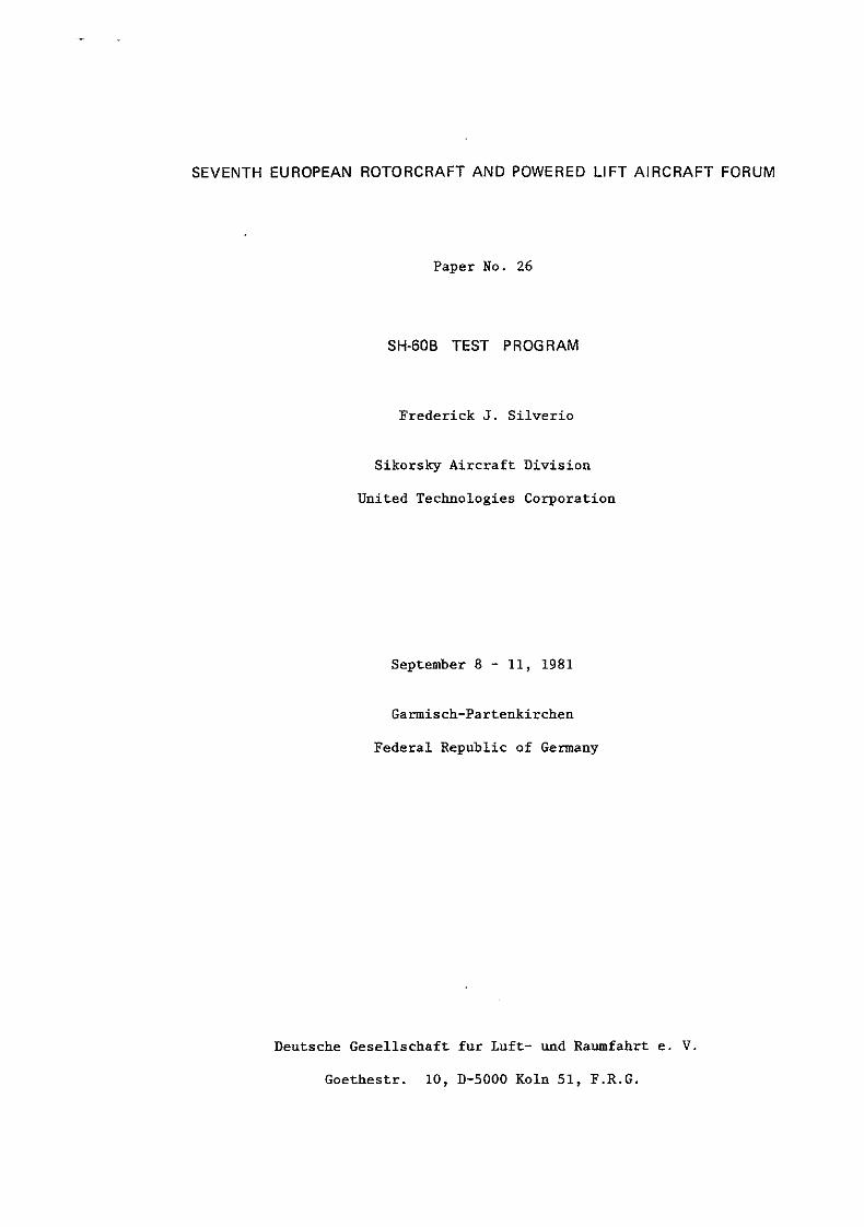
SEVENTH EUROPEAN ROTORCRAFT AND POWERED LIFT AIRCRAFT FORUM
Paper No. 26
SH-608 TEST PROGRAM
Frederick J. Silverio
Sikorsky Aircraft Division
United Technologies Corporation
September 8 - 11, 1981
Garmisch-Partenkirchen
Federal Republic of Germany
Deutsche Gesellschaft fur Luft- und Raumfahrt e. V.
Goethestr. 10, D-5000 Koln 51, F.R.G.

1. Abstract
SH-60B TEST PROGRAM
Frederick J. Silverio Chief of Systems Integration
Sikorsky Aircraft Division United Technologies Corporation
1980-81 was a period of maturity for the U.S. Navy LAMPS MK III weapon systems. Following the SEAHAWK Helicopter's first flight in December 1979, the test program brought together the major elements of the weapon system including the ship, air vehicle, RAST and the vast array of mission avionics--both airborne and ship borne, and culminated in the first integrated shipboard testing on 18 December 1980 when Aircraft 161169 made its maiden landing aboard the U.S. S. Mcinerney (FFG-8) at Mayport, Florida.
From the outset of the program, the basic SEAHAWK Helicopter possessed high maturity owing to the high degree of commonality of its dynamic components with those of the BLACK HAWK Helicopter. Sikorsky completed its basic aircraft shakedown program in April 1980 and proceeded directly into a structured test program including five (5) Navy preliminary evaluations. The aircraft will enter formal BIS trials this year and complete its full-scale development program in February 1982, followed by fleet deliveries in 1984.
2. Mission and Description
The SH-60B is a derivative of the UH-60A BLACK HAWK, modified to U.S. Navy requirements to meet its mission requirements for anti-submarine warfare (ASW) and anti-ship surveillance and targeting (ASST). In these roles, the SEAHAWK as an adjunct to the sensor and attack systems of the surface ship, extends the range of the ship's sea control influence over the horizon.
The aircraft, configured for ASW, operates at a mission gross weight of 20,027 pounds and is powered by two T700-GE-401 engines. The aircraft retains the key qualified elements of the BLACK HAWK's dynamic system and power train including the main transmission, input and accessory modules, main rotor shaft, hub, blades--except for root end blade fold modifications, intermediate gear box, tail rotor gear box, tail rotor, APU System and power plant installation.
The major modifications required for shipboard compatibility and mission for SEAHAWK are: addition of mission avionics, which includes ESM, data link, radar and acoustic processing as key elements, weapon stations, sonobuoy launcher system, increased fuel capacity, HIFR, fuel dump, rescue hoist, blade de-ice system, MAD, air conditioning system, blade fold, pylon fold, auxiliary floatation, rotor brake, heavy weather tiedown, UHF position locator, and an airborne RAST system.
It is necessary to briefly mention the above changes in order that the test program elements and extent of flight test hours are understood.
3. SEAHAWK Preflight Ground Tests
Prior to obtaining flight release, certain tests were required to ensure airworthiness. A 100-hour whirl test of the rotor system with fold hardware was required.
26-1

The actual tests consisted of ten hours of basic stability and control, structural and dynamic and performance surveys followed by 100 hours of endurance testing, including 125% overspeed tests. Other tests conducted on A/C 169 were: fuel system operation and calibration, hydraulic system proof and operation, control system proof and operation, airframe shake test, and tail rotor drive shaft overspeed tests. Fatigue testing of at least one sample of each SEAHAWK unique dynamic component was accomplished with adequate strength demonstrated. Completion of the above tasks resulted in clearance for first flight.
4. SEAHAWK Development Tests - Shakedown
Following SEAHAWK's first flight on 12 December 1979, the initial shakedown phase of the flight test program was begun with A/C 161169 outfitted with a 300 channel flight test instrumentation package which was configured for accurate weight and space simulation of the mission avionics package in order to simulate the dynamics of the mission-configured aircraft. Critical aspects of each flight discipline--structures, dynamics, handling qualities, powerplant, and performance--were evaluated. This process began with the first flight day when two engineering data flights were conducted. The first was a hover and low speed evaluation. The second flight included full power climbs, 45° angle of bank (AOB) turns and full autorotations--an dmbitious first flight program, even for a derivative aircraft. These initial flights showed low vibration, good control harmony, no structural surprises, and performance as expected.
Subsequent shakedown flights quickly achieved the envelopes for load factor and cg established for the early flight test phase, that is, 170 knots airspeed, 2g load factor, and 60° AOB turns at mission gross weights, Figure 1. Flights were conducted with various stores configurations and at the extremes of the weight--cg envelope, Figure 2.
LOAD FAC'rOR ,.,
ENVELOI'E ESTABLISHED IN SHAKEDOWN
.,.~--------~--~----,---~----, . .,
"' "' AIRSPEED, KNOTS
FIGURE 1. SH-608 SHAKEDOWN LOAD FACTOR ENVELOPE
GROSS 19000
WEIGHT POUNOS 18000
/ SHA.KEOOWN TEST DATA QTAKE-Off 6 LANDING
·~·4---rL-r--r--r--~~--~~~~-4 lC-4 :WS :MB
CENTER 0~ GRAVITY STATION
FIGURE 2. SEAHAWK GROSS WEIGHT - CG ENVELOPE
The test data quickly showed that the SEAHAWK was sufficiently mature to allow non-instrumented flying on the second and subsequent mission avionics configured SH-60B' s and that the other phases of the aggressive LAMPS MK III flight program could begin on schedule.
As with any new aircraft, progress of the shakedown phase was tempered by normal development problems. All of these issues were successfully resolved on schedule by a combination of analysis, intuition, ground test and flight test, and permitted the test program schedule to be maintained. To illustrate this process, several of these development issues are discussed below.
A vertical vibration at the first vertical fuselage bending mode (6.5 Hz) was noted occasionally during recovery from high-speed autorotations and a few other maneuvers, Figure 3. AFCS (Automatic Flight Control System) ON aggravated the situation and the vibration was sustained on at least one occasion until the AFCS was turned off. Relocation of the AFCS SAS pitch gyro to the first bending mode
26-2
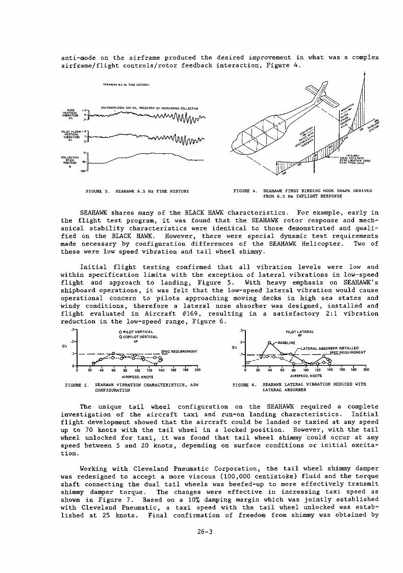
anti-mode on the airframe produced the desired improvement in what was a complex airframe/flight controls/rotor feedback interaction, Figure 4.
S£Aii.O.WK 6.5 H> TIME HISTORY
COllECTIVE
pJJ;~~ 50'j----../ •
FIGURE 3. SEAHAWK 6.5 Hz TIME HISTORY FIGURE 4. SEAHAWK FIRST BINDING MODE SHAPE DERIVED FROM 6.5 Hz INFLIGHT RESPONSE
SEAHAWK shares many of the BLACK HAWK characteristics. For example, early in the flight test program, it was found that the SEAHAWK rotor response and mechanical stability characteristics were identical to those demonstrated and qualified on the BLACK HAWK. However, there were special dynamic test requirements made necessary by configuration differences of the SEAHAWK Helicopter. Two of these were low speed vibration and tail wheel shimmy.
Initial flight testing confirmed that all vibration levels were low and within specification limits with the exception of lateral vibrations in low-speed flight and approach to landing, Figure 5. With heavy emphasis on SEAHAWK' s shipboard operations, it was felt that the low-speed lateral vibration would cause operational concern to pilots approaching moving decks in high sea states and windy conditions, therefore a lateral nose absorber was designed, installed and flight evaluated in Aircraft 11169, resulting in a satisfactory 2: 1 vibration reduction in the low-speed range, Figure 6 .
G'•
. 3 0 PILOT VERTICAL
0 COPILOT VERTICAL .2 " ·' ---·+-~~~~--r--r-ru,--.--~~ . . . . - ,. - - - -
AIRSPEED, KNOTS
FIGURE 5. SEAHAWK VIBRATION CHARACTERISTICS, ASW CONFIGURATION
.3
.2
G'•
·'
•
PILOT LATERAl.
" SASEt.INE
. . . . - ,. ~ -- -AIRSPEED, KNOTS
FIGURE 6. SEAHAWK LATERAL VIBRATION REDUCED WITH LATERAL ABSORBER
The unique tail wheel configuration on the SEAHAWK required a complete investigation of the aircraft taxi and run-on landing characteristics. Initial flight development showed that the aircraft could be landed or taxied at any speed up to 70 knots with the tail wheel in a locked position. However, with the tail wheel unlocked for taxi, it was found that tail wheel shimmy 'could occur at any speed between 5 and 20 knots, depending on surface conditions or initial excitation.
Working with Cleveland Pneumatic Corporation, the tail wheel shimmy damper was redesigned to accept a more viscous (100,000 centistoke) fluid and the torque shaft connecting the dual tail wheels was beefed-up to more effectively transmit shimmy damper torque. The changes were effective in increasing taxi speed as shown in Figure 7. Based on a 10% damping margin which was jointly established with Cleveland Pneumatic, a taxi speed with the tail wheel unlocked was established at 25 knots. Final confirmation of freedom from shimmy was obtained by
26-3

conducting taxi tests over a Navy arresting cable set at various angles to the runway.
CRITICAL DAMPING
'
0
10 -- 10% Oc\~~~~~lTABILITY-- -- _ 1 ' ' STABLE (NO SHIMMYI I
'"
' ' ' v
0
SHIMMY MAX. PERMISSABLE TAXI SPE£0
0
~ "' GROUP-IOSPHO, KNOTS
100,000 C.S..·SHIMMY CAMPER
FIGURE 7. SEAHAWK TAIL WHEEL SHIMMY BOUNDARY SOLID TORQUE SHAFT
The first mechanical stability characteristics of the SEAHAWK in RAST operations were successfully evaluated at NAEC, Lakehurst, Figure 8. The aircraft was found to be stable under the full range of cable tensions, stick positions, and percent airborne. After verifying that the aircraft was stable under normal conditions, the tests were repeated with the landing gear in various degraded modes, including partially inflated tires and oleos and fully flat tire and oleo. A typical test result taken with a flat tire is shown in Figure 9 and illustrates the mechanical stability test technique. As shown, the cyclic stick is stirred at 2/3 per rev to excite the aircraft roll oscillation and the rate of decay after stick excitation is stopped is measured to determine stability margin. The final confirmation of the SEAHAWK mechanical stability characteristics with the RAST came with the successful shipboard landings aboard the U.S.S. Mcinerney in January 1981.
FAILURE MOOE; FLAT RIGHT OLEO
ROLL ACCELERATIQH
LATERAL STICK
CABLE TENSION: 3500 LB
'CICc •3.5%
EXCITATION SToPPED LATERAL GO~ STICK
POS~TUlN 40 1-------.MN>WAArJ-------'" > CYCLIC STICK EXCITATIOP-1
LONGITUDINAL STICK 60
POSITION
Wl LONGITUDINAL CYCLIC
~+-~~~~,-,-~~-r-r-r-r-r-r-, "-.oo, = ' ' ' ' ' ' " ' ' ' • '" " " " " "
TIME. SECONO$
FIGURE 9. RAST MECHANICAL STABILITY EVALUATION FIGURE S. RAST MECHANICAL STABILITY
5. Pitot-Static System
The initial pitot-static system installation was the identical UH-60A BLACK HAWK type with the probes mounted on the cockpit canopy over the pilots' heads. In SEAHAWK mission profiles, the rotor vortices produced a discontinuity in the airspeed signal between 50 and 70 knots in climbout, Figure 10. This discontinuity caused a momentary decrease in the indicated airspeed--a key signal input to the controlled stabilator angle of attack, Figure 11, which resulted in a momentary nose-down pitching of the aircraft. Since the pilot's cue was decreasing airspeed and a corresponding nose-down attitude due to stabilator incidence, this characte~istic was not acceptable for night or IFR operations.
The discontinuity was attributed to rotor wake passage over the pitot-static probes at certain combinations of airspeed, collective setting, body attitude, and rate of climb. Relocation of the probes to the sides of the nose of the aircraft moved the anomaly to an airspeed below which the stabilator "programming is not affected~ This relocation was coupled with the movement of the static sources to
26-4

flush locations just behind the cockpit doors to provide smooth operation of the barometric altimeter and IVVI locations.
INQICA.HO
A.IASPUD. 6C
KNOTS
OAIGINA.L P~OGE LOCATION
tO 15 20 2~ 30 35
TIME. SECONOS
NO$£ PIIOBE LOCATION
10 15 20 2S 3C 3S
TIME. SECONDS
FIGURE 10. SEAHAWK PITOT-STATIC SYSTEM DEVELOPMENT TAKE-OFF AND CLIMB-OUT TIME HISTORIES
6. AFCS System Development
STAOILATOA ANGLE 20
OEGRUS
AIIISPEED. KNOT$
FIGURE 11. STABILATOR INCIDENCE ANGLE
The SEAHAWK AFCS System architecture is based upon the BLACK HAWK System and consists of three subsystems:
1) Analog SAS (Stability Augmentation System) 2) Stabilator Control 3) Digital Flight Controls
The three subsystems operate independently of each other, except for sharing of some common sensors. Any combination of subsystem engagements provides good aircraft handling qualities. The SH-60B System is configuratively similar to the UH-60A System, but includes more than twice the functions. The SH-60B AFCS System includes the following modes of operation:
o SAS 1 (Analog) o SAS 2 (Digital, resident in software) o Hover Augmentation o Pitch Bias Actuator (Longitudinal static stick stability) o Trim (Pitch, roll, yaw and collective) o Auto Pilot:
- Heading hold - Airspeed hold - Attitude (pitch and roll) hold - Radar altitude hold - Barometric altitude hold - Turn coordination (above 50 knots) - Coupler:
- Auto approach to hover - Auto hover - Auto departure from hover - Crew hover
- Gust alleviation o Blade Fold Control Positioning
The SEAHAWK AFCS System Digital Computer is a derivative of the CH-53E unit with expanded I/0 capability which is needed to accommodate the increased mission requirements. The Analog SAS Amplifier is a derivative of the UH-60A unit.
Although based on successful existing systems, the integration and development of the AFCS on SEAHAWK was one of the major tasks of the FSD Program. The second SH-60B, Aircraft 161170, was equipped with an alterable memory AFCS computer (CORE) and AFCS test equipment. Initial flights verified the analog and digital SAS gains and developed the trim systems such that an interim "hard"
26-5

memory (PROM) This phase was
computer was available for use by the other development aircraft. accomplished in 35 flight hours.
The development of the final AFCS Program, primarily the autopilot functions, was accomplished in 85 flight hours. Some of the development improvements which evolved are discussed below.
7. Mananeuvering Stability
At bank angles of greater than 30°, the longitudinal stick force gradients were improved by fe'eding bank angle commands to the longitudinal stick to provide a force equivalent to 30% stick displacement at 70° angle of bank.
8. Airspeed Hold
This flight mode generated periodic slow oscillatory hunting above the synchronized airspeed which was corrected by a software revision to the longitudinal accelerometer filter transfer function for short-term correction.
9. Auto Approach
During auto approach transitions, excessive longitudinal stick pumping was experienced. This was the result of excessive noise inherent on the doppler signal. After evaluating a number of methods to correct this function, it was determined that extensive signal conditioning of the doppler signal provided the most acceptable procedure.
10. AFCS System Evaluation
Prior to committing the developed AFCS software program to hard memory (PROM), the Navy evaluated the AFCS performance characteristics with the CORE computer. During these evaluations, a number of control laws were implemented per their suggestion and flight validated. This procedure of retaining the soft memory for this type of evaluation proved very valuable. Software changes were easily accommodated with the CORE computer enabling the Navy to evaluate the AFCS changes on the next flight. After the last evaluation flight had been conducted with the final version of software program, it was committed to PROM memory. The Production PROM memories were subsequently installed on all five SH-60B Development Aircraft.
11. Preparation for Sea Trials
11.1 Performance
Meeting basic performance requirements is fundamental to the conduct of mission profiles used for the SH-60B System development. Meeting specification performance also assures that adequate margin is available for emergency situations should they arise. Prior to sea trials, basic performance data were reviewed and compared to specification guarantees. This comparison indicated that guarantees would be met or exceeded and no further development was required in this area in advance of sea trials.
SEAHAWK PERfOR~ANCE GUARANTHS
GUARANTEE CONDITION$ ACHIEVED
(AS MODifiED BY GROSS WEIGHT AIRMASS I'QWER IBASEOON
DEVELOPMENT CONTRACT! FLIGHT TEST)
LEVEL FLIGHT AIRSPEED 200Z7LB """" "' 130.5 KT OF 130 KT (MISSION WTI 70.,<>F (MAX. CONT PWR) (FIGURE 121
VERTICAL RATE OF CLIMB 20027 LB SEA LEVEL 30MIN 850 FPM Of 1!32 FP~ 89.8" f TRANS. LIMIT (fiGURE 131
(MAX. All OW. PWRI
SINGLE ENGINE RATE Of 141131 LB SEA LEVEL 95%CRP 005 Fl"'l CLIMB OF 576 FPM AT (JETTISONED STORES. 89.a<>F ($1NG~E ENGINE !fiGURE 1~) 30 KT Alfl!li'EEO 20 MIN FUEL) AT Vof CONTINGENCY
RATEOPWFI)
26-6

"AT((,CL1"f..>TIWI"
FIGURE 12. SH-60B LEVEL FLIGHT PERFORMANCE, FIGURE 13. SH-60B VERTICAL RATE OF FIGURE 14. SH-608 SINGLE ENGINE PERFORMANCE, ASW CONFIGURATION, 5000 FEET, CLIMB ASW CONGIGURATION, STORES JETTISONNED, SEA LEVEL, 70.4°F SEA LEVEL, 89.8°F 89.8°F, 30 KNOTS
11.2 Fuel Dump
The specification fuel dump rate of 800 lb/min was exceeded in aircraft ground and flight tests; however, flight test resulted in minor impingement of fuel on the aft tail cone and stabilator while dumping during autorotations. A modification in dump tube tip geometry was incorporated which reduced the exit area of the fuel dump tube slightly and increased the exit velocity sufficiently to achieve adequate clearance in all normal flight regimes.
11.3 Flight Loads Survey
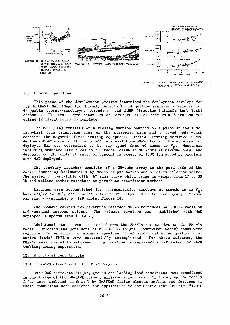
The next phase was the flight loads survey, where data were obtained in all flight regimes of the SH-60B mission spectrum, for the dynamic component substantiating parameters, defined by the BLACK HAWK Program or by SEAHAWK bench fatigue tests as applicable. A typical result for blade edgewise bending is shown as Figure 15.
The flight loads survey results, when combined with component bench test fatigue strength data and the SH-60B mission spectrum, define the component retirement times. This phase was accomplished in one month and 36 flight hours on Aircraft 169, and, in general, results were as predicted.
11.4 Interim Hard Landings
An interim hard landing demonstration was conducted to quality the SEAHAWK for the Shipboard Envelope Development. The required airframe drops using the Static Test Article have been successfully completed and final hard landing demonstrations to 12 feet per second sink speed are planned later in the program. The interim demonstration consisted of side drift landings to a sloped pad, and vertical landings to 9.6 fps sink speed at the Naval Air Test Center, Figure 16, and 9.6 fps RAST landings on the elevated platform at NAEC.
The side drift landings were intended to simulate landings on a rolling deck. SEAHAWK was the first Navy helicopter to be subjected to this type of landing gear test. The specification levels were 5 fps drift and 9° slope. These values were later verified to be conservative based on actual ship landing data. Six (6) conditions were evaluated: aircraft centerline parallel to the "ridge" line and 45° no~e-up and nose-down the slope conducted with both left and right drift. The end points were achieved and the test was accepted by NAVAIR as meeting the shipboard requirements.
The vertical landings, both free and RAST assisted, were accomplished without difficulty. The results are typified by the vertical loads shown in Figure 17, where the loads for the "free" and haul down" landings are comparable and well within allowable limits.
26-7
-VJSRATORV BtNDINC MOMEIIT IN.~B
FIGURE 15.SH-60B FLIGHT LOADS SURVEY RESULTS, MAIN FIGURE 16. INTERIH HARD LANDINGS TEST-NATC ROTOR BLADE EDEGWISE
·.::~ """'""~' ·~:-=·· ./ LHTIAAI~ ~DQ(l •• •-...,.O-~-Or-O-· ... ·_·_:_______...,._"_··,----,
BENDING MOMENT AT STATION 1
12. Stores Separation
'""T I I I • • 8 10 11
Slm< SPEED, FTISEC
FIGURE 17. INTERIM HARD LANDING DEMONSTRATION, VERTICAL LANDING GEAR LOADS
This phase of the development program determined the deployment envelope for the SEAHAWK MAD (Magnetic Anomaly Detector) and jettison/release envelopes for droppable stores--sonobuoys, torpedoes, and PMBR (Practice Multiple Bomb Rack) ordnance. The tests were conducted on Aircraft 170 at West Palm Beach and required 12 flight hours to complete.
The MAD (GFE) consists of a reeling machine mounted on a pylon at the fus~lage-tail cone transition area on the starboard side and a towed body which contains the magnetic field sensing equipment. Initial testing verified a MAD deployment envelope of 110 knots and retrieval from 50-90 knots. The envelope for deployed MAD was determined to be any speed from 40 knots to VJ!. Maneuvers including standard rate turns to 120 knots, climb at 80 knots at max~mum power and descents to 120 knots at rates of descent in excess of 1500 fpm posed .no problems with MAD deployed. •
The sonobuoy launcher consists of a 25-tube array in the port side of the cabin, launching horizontally by means of pneumatics and a rotary selector valve. The system is compatible with "A" size buoys which range in weight from 17 to 39 lb and utilize either rotochute or parachute retardation methods.
Launches were accomplished for representative bank angles to 30°, and descent rates to 2500 fpm. was also accomplished at 120 knots, Figure 18.
sonobuys at speeds up to VH' A 25-tube emergency jettison
The SEAHAWK carries two parachute retarded MK 46 torpedoes on BRU-14 racks on side-mounted weapons pylons. The release envelope was established with MAD deployed at speeds from 40 to VH.
Additional stores can be carried when the PMBR' s are mounted on the BRU-14 racks. Releases and jettisons of MK 84 SUS (Signal Underwater Sound) bombs were conducted to establish a minimum envelope of 40 knots and hover jettisons of entire loaded PMBR' s were successfully accomplished. For these releases, the PMBR' s were loaded to extremes of cg location to represent worst cases for rack tumbling during separation.
13. Structural Test Article
13.1 Primary Structure Static Test Program
Over 200 different flight, ground and landing load conditions were considered in the design of the SEAHAWK primary airframe structures. Of these, approximately fifty were analyzed in detail by NASTRAN finite element methods and fourteen of these conditions were selected for application to the Static Test Article, Figure
26-8

19. One or more of these conditions developed the critical shears and moments in all parts of the primary airframe ;;tructure. Six conditions simulated flight maneuvers; two simulated the loads developed in RAST hauldown in high sea states and the remaining six represented heavy landings. The flight and ground condition loads were all applied up to ultimate load (1.5 x limit load).
In each case, all of the analytical shears and moments in the portion of the airframe being tested were generated by externally applied loads developed by hydraulic cylinder and distributed into the airframe. The Test Article was suspended from a dummy main rotor head so that all unbalanced shears and couples accumulated at the rotor head and were reacted to "ground" in a manner representative of, but also the reverse of, the flight situation. All applied loads were in~reased proportionally using a special multi-channel hydraulic control system designed specifically for this purpose.
FIGURE 18. SONOBUOY EMERGENCY JETTISON FIGURE 19. STATIC TEST ARTICLE
Based on these tests, only three regions of the airframe were modified during the program by increase of load skin thickness, the addition of panel breaker sub-stringers, or the addition of stringer doublers. With these modifications installed, no permanent structural deformations occurred even at Ultimate Load.
13.2 Airframe Drop Tests
These tests form a bridge between the landing gear oleo efficiency drop tests and the heavy landing phase of the flight test program.
The airframe was dropped over 250 times and critical loads were developed in the main gear, the tail gear and the tail bumper by varying gross weight, cg location, pitch and roll attitude, sink speed, tire and oleo pressures, and oleo oil volume. The effect of run-on landing speed was also investigated by spinning the wheels backwards and decelerating them upon 11 landing11
•
For each drop of the test article, simulated rotor lift equal to the weight of the test article was developed by an air cylinder and large-volume accumulator system. The test article "landed" on platforms instrumented to measure the ground reaction forces in the three principle universal axes. These parameters, and key airframe parameters such as landing gear loads and strokes, airframe accelerations and stresses, and rotor lift were recorded. Each series of drops was made at successively higher sink speeds until the required maximum (12 fps) was achieved. Overload drop tests of the main and tail· gear were also made at design alternate gross weight and at sink speeds- which developed 125% of the maximum oleo load recorded during the Basic Gross Weight drop tests. No design changes resulted from these tests.
26-9

14. RAST Development
Aircraft recovery with RAST is required ·to achieve landings and hangaring on small ships in Sea States above 4. The airborne portion of the RAST System includes a main probe to which cable tension is applied to bring the aircraft down to the deck under positive control. The main probe upon touchdown is captured in the arresting beams of the Rapid Securing Device. Simultaneously, a small probe on the tail landing gear engages one of several slots on a deck grid to provide yaw constraint and 'thereby completes the process of firmly securing the aircraft to the deck.
Traverse is then accomplished by winching and moving the RSD along a track into the hangar.
The initial envelopes determined were: initiate recovery from an 8-foot altitude (radar altimeter) and up to a 3-foot offset in any direction, hover tension 1200 lb, and hauldown tension 4000 lb. Manual and electrical releases from the hauldown cable can be accomplished at loads up to 4000 lb and cable angles of up to 70° from the vertical. Testing will continue and envelope expansion is feasible as a result of operational testing scheduled for the summer and fall of 1981.
15. Navy Pilot Evaluations
Four Navy Pilot Evaluations were conducted between July 1980 and February 1981 and totalled 90 flight hours on three aircraft.
15.1 NPE-lA
This first Navy look at SEAHAWK was conducted on Aircraft 170, the AFCS development aircraft, in July 1980. This initial evaluation was primarily directed toward handling qualities and performance, although all characteristics were considered. The AFCS Program, in accordance with program schedules, had not been fully developed at this time, therefore only the basic analog and digital SAS, and trim functions were evaluated.
No major discrepancies were noted in the initial pilots' report and the necessary minor changes were implemented for later evaluation.
15.2 NPE-lN
This was the "night lighting 11 evaluation and was conducted on Aircraft 172, a mission-equipped aircraft, at the Naval Air Test Center in August 1980. Again minor corrective actions for desired changes by the Navy evaluation team were incorporated in parallel with the on-going program.
15.3 NPE-lB
This was the initial Navy evaluation of the RAST (Recovery Assist and Secure Traverse) System. It was conducted immediately after the initial flight development of the airborne RAST on the EFP (Elevated Fixed Platform) at the Naval Air Engineering Center, Lakehurst, New Jersey, on Aircraft 169 in September 1980. This testing resulted in minor modifications to the RAST prior to shipboard trials to improve reliability, and emergency release operations and procedures.
15.4 NPE-lC
This was conducted in two parts (December 1980 and February 1981) to avoid conflict with the Shipboard Envelope Development Program which also used Aircraft
26-10

169. Its purpose was to repeat NPE-lA testing with corrective actions installed and to evaluate new features not available before.
An added evaluation was a visit to Mayport, Florida, for the initial dockside landings, using RAST on the first SEAHAWK-compatible ship, the U.S.S. Mcinerney, FFG-8. This was also the first opportunity to check RAST traverses into the ship's hangars. All aspects of this testing were successfully completed and a number of rec6mmended minor changes were incorporated prior to the initial at-sea deployment.
The test aircraft was equipped with a "final PROM" AFCS computer, incorporating NEP-1A changes, and was fully instrumented for performance flight testing.
The Navy performance objectives were achieved and documented such that the scheduled formal Performance Demo will not be required.
16. Shipboard Envelope Development
The most critical phase of the SEAHAWK development program was the initial at-sea deployment of an instrumented helicopter, No. 169, on the U.S.S. Mcinerney, FFG-8, to determine the "Dynamic Interface" envelopes and procedures for flight and deck operations. The system design point to be achieved was Upper Sea State 5, which involves winds up to 27 knots and wave heights to 17 feet. Ship roll angles of up to 30° were expected in these conditions.
The testing was accomplished in January 1981 and was entirely sucCessful. 45 flight hours were flown and more than 250 landings were made, Figure 20, aproximately half being RAST hauldowns and the remainder "free deck" into the RSD ("trap 11
). Although actual Sea State 5 was not encountered with winds over the deck up to 45 knots, ship roll angles of up to 28° were generated by steaming parallel to the wave troughs, thus providing the effects of the required Sea State.
Flight operations under these conditions, with spray and waves washing over the flight deck so that the hovering helicopter was continually wetted and the pilot occasionally lost sight of the ship, were deemed "routine11 by the Navy Test Director on board. Test data from the dynamic components, airframe, and landing gear were within expected values and no restrictions on the helicopter resulted for any of these conditions.
Envelopes were established for normal operations and degraded modes such as SAS and boost failure. The SH-60B/FFG-8 Dynamic Interface which resulted from these tests did not utilize the full potential of the SH-60B/RAST System but still represents the largest helo/ship envelope of any in U.S. Navy inven~ory. Figure 21 shows two of the envelope diagrams which are now in use by an operational test deployment of two mission-equipped SEAHAWK on the U.S.S. Mcinerney. These limits are considerably less than that flown on Aircraft 169 and can be expected to be expanded as experience accumulates.
FIGURE 20. AT SEA OBJECTIVES
26-ll
m
SHIP HEAD
~~~~;~~DAY SINGlt FAilURE EXCEPT BOOST
= OAV DUA~ FAILURE. DAV BDOST FAilURE. 0/1 NIGHT SINGLE fAilURE
DEGRADED MODES 0-:!"PITCH 0-00 ROll
FIGURE 21. SH-608/FFG-8 DYNAMIC INTERFACE PLOTS WING AZIMUTH AND RELATIVE SPEED

17. Reliability Development
U.S. Navy reliability and maintainability requirements for the SH-60B SEAHAWK Air Vehicle constituted a major technical challenge.
Achievement of these mature R&M levels by the conclusi'on of the planned development program demanded strong emphasis on reliability in three key areas:
o Systems common to the UH-60A BLACK HAWK representing 58% of allocated reliability requirements developed by the U.S. Army-Sikorsky BLACK HAWK Reliability Program in more than 7500 flight hours of reliability development experience.
o Systems unique to the SH-60B representing 35% of allocated reliability requirements being developed by the U.S. Navy-Sikorsky SEAHAWK Reliability Program.
o GFE systems representing 7% of allocated reliability requirements being developed by parallel Government-GEE contractor reliability programs.
18. U.S. Navy SH-60B R&M Requirements
To ensure that the SEAHAWK-unique systems achieve allocated requirements in a short, 2000 flight hour development program, the Navy wisely chose to implement the most comprehensive helicopter systems reliability development test program.
Requirements:
Mean Flight Hours Between Failures ASW Mission Reliability (3.67 hours) ASST Mission Reliability (4.67 hours) DMMH/FH Operational Availability (%)
19. Reliability Development Test Program Elements
4.6 0.9898 0.9907 2.477
91.5
During 1980, Sikorsky implemented the. SEAHAWK RDT (Reliability Development Test) Program--the most comprehensive systems reliability development program ever undertaken by a helicopter manufacturer. For the first time, SEAHAWK RDT's applied the principles of operational cycling under controlled environments, common in electronics testing, to complex mechanical systems. These tests simulate 5,000 hours of system usage, uncover failure modes, and evaluate reliability improvements.
Experience shows that approximately 7000 flight hours of testing are required to develop mature reliability in dynamic, mechanical and electronic components of helicopter weapon systems.
The reliability of hardware common to the BLACK HAWK was developed during 7500 hours of BLACK HAWK testing and production experience. The duration of the SEAHAWK flight test program is approximately 2200 hours which is adequate to mature most airframe components but is not adequate for the more complex systems selected for reliability development testing. Without additional testing, the reliability of these subsystems would reach only 65% of their, mature requirement. SEAHAWK RUT's provide the balance of test time equivalent to 5000 hours of flight test required for additional reliability development, Figure 22.
26-12

19.1 ROT Environment
Environmental conditions applied during ROT's reflect the SEAHAWK's realworld service environment, and include temperature, humidity, salt fog, and vibration. Temperature and humidity levels and exposure durations represent the MIL-STD-210 worldwide distribution of climatic conditions for naval helicopters. To avoid the need for additional vibration test facilities, mechanical systems were exposed to accelerated 'levels of vibration applied at the predominant blade passage frequency (17.2 Hz) to simulate 5,000 flight hours of fatigue damage in a 500 hour vibration test. All other environmental conditions are applied in real time.
19.2 Electronic Component ROT
The SEAHAWK Electronics and Blade De-ice ROT's are the most extensive electronics tests ever undertaken by Sikorsky. The tests were conducted in the test facilities of the Norden Division of United Technology Corporation in Norwalk, Connecticut. Testing was performed in a Thermotron AGREE-type environmental chamber capable of inducing controlled environments and providing continuous test and failure monitoring. Twenty test specimens were tested (four of each component) in order to reduce chamber time. The components tested were:
SAS Amplifier AFCS Control Panel Sonobuoy Controller RAST Control Panel Linear Blade Fold Position Transducers
The twenty test specimens were continuously exercised while exposed to a controlled MIL-STD-2068 environmental profile as shown in Figure 23.
o -65°F to 185°F storage temperatures o -40°F to 140°F operating temperatures o thermal cycling along 8°F/minute temperature ramps o 0 to 80% relative humidity, o salt fog o 1.5g vibration at 17.2 Hz the predominant 4 per rev main rotor
forcing frequency
EL.!CT~0NICSY$TEMS !IOOCIIfOURS
D£-1Cf5'1'$TU< :OOOH(li)RS -Of HI(JHTTIME INICINOCONOITI<.lNSPUIMILSTD-'10
:IOI<O.uOV UUNCH 12.!500 LAUNCHCVCLU !IOOU..MIQIDN$1N5000 RIOHT HOUIIS,Ioi""I"""M SY$TEN U.WOO LOADI\INLOAD Of 25S()NOWOy$ t.A.UNCHU>PER A1lW MISSION
cvcus laciHAIIL!>QWNI'rMV- USOMI!IIIQHCINiiOCJ:I fLI(lHT HOURS EIISECVCLU
lncl FCi.I>ISPIIEAD lmM1$$10141N !1000 FLICHTHOU~S CVCLU
!KIOOCAIIH<OOOACI'll<• Clll'l'l f.'<TAV AN!IE<liiESI:PIIEHI<lHT, DAILY, CLDU CYCLU PE"IOCOCAIIOUNSCHEDULED .... INTtNAHCE;
RUCUE HQI$T AND H,R QPUIATION$ IN ~111>:1 HIQtffHOUIIS
JQOO E-MT DOOR 01'91· OAILT. PORIOOIC ANOUN.scJ<EOULEOW.O.IN-CI.ou: CVCLU TENA"'CE IN 5000 fliCIHT HOURS
500C roi'-DUT $TV' Dl'£1-1 ~~EFLIOHT, DA.IL Y ,£RIOOIC .tiiO Ym<:W£0\/L£0 .CLOSE CYCLES .. .tliiT£11AHCE IN SOOII HOIH\S
FIGURE 22. RDT DURATIONS REPRESENT 5000 FLIGHT HOUR USAGE
19.3 Computer Aided Test Control
TllfiiM~~ PROFILE
EQUIPMENT '""''"' OPERATION : .,oMu
I i
VIBRATION
l O" : ~ I J
I """" '"'"'" : ~ .. ~w~~ir~: -..,;,--'J""' '----+----'--,.,---'........ ' FOG I I
' l-----UST CYC~~ ( 1U HOURS )------1
FIGURE 23. SH-608 ELECTRONIC COMPONENTS RELIABILITY DEVELOPMENT TEST CYCLE
A test console comprised of a Digital Equipment Corporation (DEC) PDP-11 digital computer and a Sikorsky designed Interface Control Unit provided the automation necessary in a test of this scope. The test console automatically exercised all twenty test specimens to simulate typical SEAHAWK service use while monitoring performance. The test console was designed to:
26-13

Generate more than 170 analog and discrete input signals, simulate more than 280 electrical load paths and monitor more than 170 outputs every 100 milliseconds. Exercise SAS amplifiers through maneuvers and steady-state flight and simulate self-test operation. Cycle AFCS control panels through three input conditions and direct manual operation of 56 control switches. Exercise Sonobuoy Launch Electronic Controllers by simulating sequential launches "of all 25 sonobuoys every 45 minutes and jettisons once a day. Daily, simulate sonobuoy launch faults, such as a stalled motor and low pneumatic pressure, to exercise built-in test (BIT). Honitor the RAST control panels during flight and simulate a complete hauldown cycle once a day by directing the operator to set control switches in the prescribed sequence, simulating inputs and loads and monitoring performance. Cycle the Bladefold Linear Position Transducers to simulate in-flight motion of main rotor controls and check performance daily in a simulated bladefold. Provide automated failure detection and shutdown and record the behavior of parameters just prior to shutdown as an aid to trouble-shooting, failure analysis, and corrective action.
The test console also automated the Blade De-Ice RDT being performed concurrently under controlled environmental conditions. For this test the console performed the following functions:
Simulated inputs and loads representative of service-use 1c1ng conditions Controlled the sequence of operations through four modes of de-ice operation Honitored component performance Directed a daily test mode and exercised fault detection by simulating an open blade heater Haintained and reported test status Alerted the test operator of failures Identified failed components
The degree of automation afforded by the test console has saved one calendar year and five man-years in the conduct of these tests.
19.4 Sonobuoy Launcher System RDT
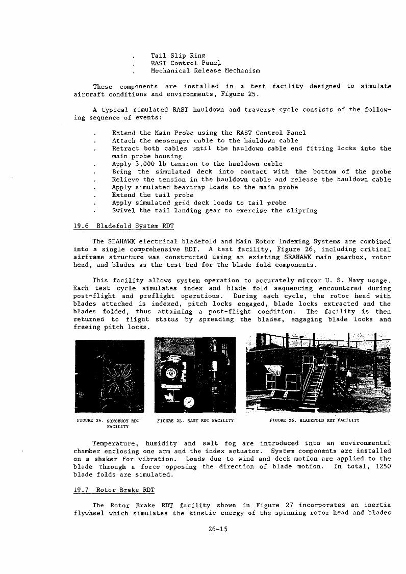
The Sonobuoy RDT develops the reliability of the SEAHAWK pneumatic sonobuoy launch system by simulating 22,500 sonobuoy launches while simultaneously subjecting the system to critical environments. The Sonobuoy launch system, consisting of the pneumatic supply module, distribution module, electric controller, and sonobuoy launch rack assembly, is mounted on an outdoor test facility, Figure 24. Extreme temperature and humidity conditions are applied using a portable environment enclosure. The test includes all phases of Sonobuoy launch system operational usage including normal sonobuoy launches, jettison launches, and exposure to handling damage in . 22,500 sonobuoy launch container load-unload cycles.
19.5 RAST System RDT
The RAST RDT tests the entire RAST System which is comprised of:
Hain Probe Hain Probe Hoist Unlocking Actuator Tail Probe Assembly
26-14
Tail Slip Ring RAST Control Pane~ Mechanical Release Mechanism
These components are installed in a test facility designed to simulate aircraft conditions and environments, Figure 25.
A typical simulated RAST hauldown and traverse cycle consists of the following sequence of events:
Extend the Main Probe using the RAST Control Panel Attach the messenger cable to the hauldown cable Retract both cables until the hauldown cable end fitting locks into the main probe housing Apply 5,000 lb tension to the hauldown cable Bring the simulated deck into contact with the bottom of the probe Relieve the tension in the hauldown cable and release the hauldown cable Apply simulated beartrap loads to the main probe Extend the tail probe Apply simulated grid deck loads to tail probe Swivel the tail landing gear to exercise the slipring
19.6 Bladefold System RDT
The SEAHAWK electrical bladefold and Main Rotor Indexing Systems are combined into a single comprehensive ROT. A test facility, Figure 26, including critical airframe structure was constructed using an existing SEAHAWK main gearbox, rotor head, and blades as the test bed for the blade fold components.
This facility allows system operation to accurately mirror U. S. Navy usage. Each test cycle simulates index and blade fold sequencing encountered during post-flight and preflight operations. During each cycle, the rotor head with blades attached is indexed, pitch locks engaged, blade locks extracted and the blades folded, thus attaining a post-flight condition. The facility is then returned to flight status by spreading the blades, engaging blade locks and freeing pitch locks.
FIGURE 24. SONOBUOY ROT FACILITY
FIGURE 25. RAST ROT FACILITY fiGURE 26. BLADEFOLD RDT FACILITY
Temperature, humidity and salt fog are introduced into an envirorunental chamber enclosing one arm and the index actuator. System components are installed on a shaker for vibration. Loads due to wind and deck motion are applied to the blade through a force opposing the direction of blade motion. In total, 1250 blade folds are simulated.
19.7 Rotor Brake RDT
The Rotor Brake RDT facility shown in Figure 27 incorporates an inertia flywheel which simulates the kinetic energy of the spinning rotor head and blades
26-15

at 50% NR. From this rotor speed, the brake is designed to stop the rotor in 15 seconds or less, 400 times.
In addition to the typical stop cycle, the test demonstrates that the brake does not slip with application of simulated engine torque of 915 ft-lb (two engines at ground idle).
Rotor brake test results show a better-than-50% margin in brake life characteristics demonstrating a 670-stop wear life compared with a 400-stop specification requirement.
As stated previously, Reliability Development Testing is required to develope this equipment to mature reliability requirements. Testing under service use environments has uncovered 40 failure modes not detected in flight tests or qualification bench tests. A description of a few of these follows:
Temperature cycling of the de-ice slipring uncovered cracking of wire insulation due to thermally induced expansion and shrinkage. An insulation with improved thermal characteristics has been incorporated. Temperature cycling of the AFCS control panel induced cracks in the solder joints of multi-layer flex print assemblies. Interlayer solder joints were replaced with plated-through holes and the flex print layers were assembled into bonded assemblies to eliminate preload. Low temperature operation of the sonobuoy launch pneumatic rotary valve disclosed that differential thermal contraction of the rotating duct and its support bearing combined with pneumatic pressure within the duct caused the rotating duct to slip within its support bearing, bind against the valve housing, and jam. Mechanical retention has been incorporated to prevent slippage of the duct within the bearing. Operation of the blade fold linear position transducer under accelerated vibration resulted in wear-through of the slipring track, causing noise in the transducer electrical output. The track finish was thickened and changed to more wear resistant metal with a smoother surface finish.
At this time, as shown in Figure 28, the reliability of equipment undergoing these ROT tests has grown to 75% of the mature requirement as opposed to only 58% utilizing knowledge gained from flight testing only.
FIGURE 27. ROTOR BRAKE ROT FACILITY
20. Conclusion
RELIABILITY PlANNED DEVELOPMENT
1000 2000 3000 (000 5000 GOOO 7000 liOURS
EQUIPM'ENT FLIGiiT TIME
FIGURE 28. SH-60B PROGRAM, CURRENT STATUS OF SEAHAWK PECULIAR DEVELOPMENT
The SEAHAWK Program to date has represented the most successful helicopter development program in United States history and clearly indicates the virtues of derivative aircraft with commonality in the drive system and up-front reliability.
26-16