sewpcc upgrading/expansion project bid ... upgrading/expansion project bid opportunity no. 601-2015...
TRANSCRIPT

SEWPCC UPGRADING/EXPANSION PROJECT BID OPPORTUNITY NO. 601-2015
WPG/474248.C2 Process Piping - General 14 Aug 2015 - Rev. 0 40 27 00 - 1 Issued for Tender
SECTION 40 27 00
PROCESS PIPING – GENERAL
PART 1 GENERAL
1.1 REFERENCES
A. The following is a list of standards which may be referenced in this section and any supplemental Data Sheets: 1. American Association of State Highway and Transportation Officials
(AASHTO): Standard Specifications for Highway Bridges. 2. American Petroleum Institute (API): SPEC 5L, Specification for Line Pipe. 3. American Society of Mechanical Engineers (ASME):
a. Boiler and Pressure Vessel Code (BPVC): 1) Section II, Part C, Specifications for Welding Rods, Electrodes,
and Filler Metals. 2) Section V, Nondestructive Examination. 3) Section VIII, Rules for Construction of Pressure Vessels. 4) Section IX, Qualification Standard for Welding, Brazing, and
Fusing Procedures; Welders; Brazers; and Welding, and Brazing, and Fusing Operators.
b. A13.1, Scheme for the Identification of Piping Systems. c. B1.20.1, Pipe Threads, General Purpose (Inch). d. B16.1, Grey Iron Pipe Flanges and Flanged Fittings Classes 25, 125,
and 250. e. B16.3, Malleable Iron Threaded Fittings Classes 150 and 300. f. B16.5, Pipe Flanges and Flanged Fittings NPS 1/2 Through NPS 24
Metric/Inch Standard. g. B16.9, Factory-Made Wrought Buttwelding Fittings. h. B16.11, Forged Fittings, Socket-Welding and Threaded. i. B16.15, Cast Copper Alloy Threaded Fittings Classes 125 and 250. j. B16.21, Nonmetallic Flat Gaskets for Pipe Flanges. k. B16.22, Wrought Copper and Copper Alloy Solder-Joint Pressure
Fittings. l. B16.24, Cast Copper Alloy Pipe Flanges and Flanged Fittings
Classes 150, 300, 600, 900, 1500, and 2500. m. B16.25, Buttwelding Ends. n. B16.42, Ductile Iron Pipe Flanges and Flanged Fittings Classes 150
and 300. o. B16.47, Large Diameter Steel Flanges NPS 26 Through NPS 60
Metric/Inch Standard. p. B31.1, Power Piping. q. B31.3, Process Piping. r. B31.9, Building Services Piping. s. B36.10M, Welded and Seamless Wrought Steel Pipe.

SEWPCC UPGRADING/EXPANSION PROJECT BID OPPORTUNITY NO. 601-2015
WPG/474248.C2 Process Piping - General 14 Aug 2015 - Rev. 0 40 27 00 - 2 Issued for Tender
4. American Society for Nondestructive Testing (ASNT): SNT-TC-1A, Personnel Qualification and Certification in Nondestructive Testing.
5. American Society for Testing and Materials (ASTM): a. A47/A47M, Standard Specification for Ferritic Malleable Iron Castings. b. A53/A53M, Standard Specification for Pipe, Steel, Black and
Hot-Dipped, Zinc-Coated, Welded and Seamless. c. A105/A105M, Standard Specification for Carbon Steel Forgings for
Piping Applications. d. A106/A106M, Standard Specification for Seamless Carbon Steel Pipe
for High-Temperature Service. e. A123/A123M, Standard Specification for Zinc (Hot-Dip Galvanized)
Coatings on Iron and Steel Products. f. A126, Standard Specification for Gray Iron Castings for Valves, Flanges,
and Pipe Fittings. g. A135/A135M, Standard Specification for Electric-Resistance-Welded
Steel Pipe. h. A139/A139M, Standard Specification for Electric-Fusion (Arc)-Welded
Steel Pipe (NPS 4 and Over). i. A153/A153M, Standard Specification for Zinc Coating (Hot-Dip) on
Iron and Steel Hardware. j. A181/A181M, Standard Specification for Carbon Steel Forgings, for
General-Purpose Piping. k. A182/A182M, Standard Specification for Forged or Rolled Alloy- and
Stainless Steel Pipe Flanges, Forged Fittings, and Valves and Parts for High-Temperature Service.
l. A183, Standard Specification for Carbon Steel Track Bolts and Nuts. m. A193/A193M, Standard Specification for Alloy-Steel and Stainless Steel
Bolting for High-Temperature or High-Pressure Service and Other Special Purpose Applications.
n. A194/A194M, Standard Specification for Carbon and Alloy Steel Nuts for Bolts for High-Pressure or High-Temperature Service or Both.
o. A197/A197M, Standard Specification for Cupola Malleable Iron. p. A216/A216M, Standard Specification for Steel Castings, Carbon,
Suitable for Fusion Welding, for High-Temperature Service. q. A234/A234M, Standard Specification for Piping Fittings of Wrought
Carbon Steel and Alloy Steel for Moderate and High Temperature Service.
r. A240/A240M, Standard Specification for Chromium and Chromium-Nickel Stainless Steel Plate, Sheet, and Strip for Pressure Vessels and General Applications.
s. A276, Standard Specification for Stainless Steel Bars and Shapes. t. A283/A283M, Standard Specification for Low and Intermediate Tensile
Strength Carbon Steel Plates. u. A285/A285M, Standard Specification for Pressure Vessel Plates, Carbon
Steel, Low- and Intermediate-Tensile Strength. v. A307, Standard Specification for Carbon Steel Bolts, Studs, and
Threaded Rod 60,000 psi Tensile Strength.
SEWPCC UPGRADING/EXPANSION PROJECT BID OPPORTUNITY NO. 601-2015
WPG/474248.C2 Process Piping - General 14 Aug 2015 - Rev. 0 40 27 00 - 3 Issued for Tender
w. A312/A312M, Standard Specification for Seamless, Welded, and Heavily Cold Worked Austenitic Stainless Steel Pipes.
x. A320/A320M, Standard Specification for Alloy-Steel and Stainless Steel Bolting for Low-Temperature Service.
y. A380, Standard Practice for Cleaning, Descaling, and Passivation of Stainless Steel Parts, Equipment, and Systems.
z. A395/A395M, Standard Specification for Ferritic Ductile Iron Pressure-Retaining Castings for Use at Elevated Temperatures.
aa. A403/A403M, Standard Specification for Wrought Austenitic Stainless Steel Piping Fittings.
bb. A409/A409M, Standard Specification for Welded Large Diameter Austenitic Steel Pipe for Corrosive or High-Temperature Service.
cc. A536, Standard Specification for Ductile Iron Castings. dd. A563, Standard Specification for Carbon and Alloy Steel Nuts. ee. A587, Standard Specification for Electric-Resistance-Welded
Low-Carbon Steel Pipe for the Chemical Industry. ff. A774/A774M, Standard Specification for As-Welded Wrought
Austenitic Stainless Steel Fittings for General Corrosive Service at Low and Moderate Temperatures.
gg. A778, Standard Specification for Welded, Unannealed Austenitic Stainless Steel Tubular Products.
hh. B32, Standard Specification for Solder Metal. ii. B43, Standard Specification for Seamless Red Brass Pipe, Standard
Sizes. jj. B61, Standard Specification for Steam or Valve Bronze Castings. kk. B62, Standard Specification for Composition Bronze or Ounce Metal
Castings. ll. B75/B75M, Standard Specification for Seamless Copper Tube. mm. B88, Standard Specification for Seamless Copper Water Tube. nn. B98/B98M, Standard Specification for Copper-Silicone Alloy Rod, Bar
and Shapes. oo. C582, Standard Specification for Contact-Molded Reinforced
Thermosetting Plastic (RTP) Laminates for Corrosion-Resistant Equipment.
pp. D412, Standard Test Methods for Vulcanized Rubber and Thermoplastic Elastomers - Tension.
qq. D413, Standard Test Methods for Rubber Property - Adhesion to Flexible Substrate.
rr. D792, Standard Test Methods for Density and Specific Gravity (Relative Density) of Plastics by Displacement.
ss. D1248, Standard Specification for Polyethylene Plastics Extrusion Materials for Wire and Cable.
tt. D1330, Standard Specification for Rubber Sheet Gaskets. uu. D1784, Standard Specification for Rigid Poly(Vinyl Chloride) (PVC)
Compounds and Chlorinated Poly(Vinyl Chloride) (CPVC) Compounds. vv. D1785, Standard Specification for Poly(Vinyl Chloride) (PVC) Plastic
Pipe, Schedules 40, 80, and 120.

SEWPCC UPGRADING/EXPANSION PROJECT BID OPPORTUNITY NO. 601-2015
WPG/474248.C2 Process Piping - General 14 Aug 2015 - Rev. 0 40 27 00 - 4 Issued for Tender
ww. D2000, Standard Classification System for Rubber Products in Automotive Applications.
xx. D2310, Standard Classification for Machine-Made “Fiberglass” (Glass-Fiber-Reinforced Thermosetting-Resin) Pipe.
yy. D2464, Standard Specification for Threaded Poly(Vinyl Chloride) (PVC) Plastic Pipe Fittings, Schedule 80.
zz. D2466, Standard Specification for Poly(Vinyl Chloride) (PVC) Plastic Pipe Fittings, Schedule 40.
aaa. D2467, Standard Specification for Poly(Vinyl Chloride) (PVC) Plastic Pipe Fittings, Schedule 80.
bbb. D2564, Standard Specification for Solvent Cements for Poly(Vinyl Chloride) (PVC) Plastic Piping Systems.
ccc. D2996, Standard Specification for Filament-Wound “Fiberglass” (Glass-Fiber-Reinforced Thermosetting-Resin) Pipe.
ddd. D3222, Standard Specification for Unmodified Poly(Vinylidene Fluoride) (PVDF) Molding Extrusion and Coating Materials.
eee. D3261, Standard Specification for Butt Heat Fusion Polyethylene (PE) Plastic Fittings for Polyethylene (PE) Plastic Pipe and Tubing.
fff. D3350, Standard Specification for Polyethylene Plastics Pipe and Fittings Materials.
ggg. D4101, Standard Specification for Polypropylene Injection and Extrusion Materials.
hhh. F437, Standard Specification for Threaded Chlorinated Poly(Vinyl Chloride) (CPVC) Plastic Pipe Fittings, Schedule 80.
iii. F439, Standard Specification for Chlorinated Poly(Vinyl Chloride) (CPVC) Plastic Pipe Fittings, Schedule 80.
jjj. F441/F441M, Standard Specification for Chlorinated Poly(Vinyl Chloride) (CPVC) Plastic Pipe, Schedules 40 and 80.
kkk. F493, Standard Specification for Solvent Cements for Chlorinated Poly(Vinyl Chloride) (CPVC) Plastic Pipe and Fittings.
lll. F593, Standard Specification for Primers for Use in Solvent Cement Joints of Poly(Vinyl Chloride) (PVC) Plastic Pipe and Fittings.
mmm. F714, Standard Specification for Polyethylene (PE) Plastic Pipe (DR-PR) Based on Outside Diameter.
nnn. F1476, Standard Specification for Performance of Gasketed Mechanical Couplings for Use in Piping Applications.
6. American Water Works Association (AWWA): a. C104/A21.4, Cement-Mortar Lining for Ductile-Iron Pipe and Fittings. b. C110/A21.10, Ductile-Iron and Gray-Iron Fittings. c. C111/A21.11, Rubber-Gasket Joints for Ductile-Iron Pressure Pipe and
Fittings. d. C115/A21.15, Flanged Ductile-Iron Pipe with Ductile-Iron or Gray-Iron
Threaded Flanges. e. C151/A21.51, Ductile-Iron Pipe, Centrifugally Cast. f. C153/A21.53, Ductile-Iron Compact Fittings. g. C200, Steel Water Pipe, 6 In. (150 mm) and Larger. h. C205, Cement-Mortar Protective Lining and Coating for Steel Water
Pipe - 4 In. (100 mm) and Larger - Shop Applied.
SEWPCC UPGRADING/EXPANSION PROJECT BID OPPORTUNITY NO. 601-2015
WPG/474248.C2 Process Piping - General 14 Aug 2015 - Rev. 0 40 27 00 - 5 Issued for Tender
i. C207, Steel Pipe Flanges for Waterworks Service, Sizes 4 In. Through 144 In. (100 mm Through 3,600 mm).
j. C208, Dimensions for Fabricated Steel Water Pipe Fittings. k. C213, Fusion-Bonded Epoxy Coating for the Interior and Exterior of
Steel Water Pipelines. l. C606, Grooved and Shouldered Joints. m. C651, Disinfecting Water Mains. n. M11, Steel Pipe - A Guide for Design and Installation.
7. American Welding Society (AWS): a. A5.8M/A5.8, Specification for Filler Metals for Brazing and Braze
Welding. b. QC1, Standard for AWS Certification of Welding Inspectors.
8. Canadian Standards Association (CSA): a. B51, Boiler, Pressure Vessel, and Pressure Piping Code. b. B139, Installation Code for Oil-Burning Equipment. c. B149.1, Natural Gas and Propane Installation Code. d. B149.2, Propane Storage and Handling Code. e. B149.6, Code for Digester Gas and Landfill Gas Installations. f. W47.1, Certification of Companies for Fusion Welding of Steel. g. W47.2, Certification of Companies for Fusion Welding of Aluminum. h. W186, Welding of Reinforcing Bars in Reinforced Concrete
Construction. 9. Manufacturers Standardization Society of the Valve and Fittings Industry, Inc.
(MSS): a. SP-6, Standard Finishes for Contact Faces of Pipe Flanges and
Connecting-End Flanges of Valves and Fittings. b. SP-43, Wrought and Fabricated Butt-Welding Fittings for Low Pressure,
Corrosion Resistant Applications. 10. National Electrical Manufacturers Association (NEMA): LI 1, Industrial
Laminating Thermosetting Products. 11. National Fire Protection Association (NFPA): 24, Standard for the Installation of
Private Fire Service Mains and Their Appurtenances. 12. NSF International (NSF): 61, Drinking Water System Components – Health
Effects.
1.2 DEFINITIONS
A. Submerged or Wetted: 1. Zone below elevation of:
a. Top face of channel walls and cover slabs. b. Top face of aeration basin walkways. c. Top face of clarifier walkways. d. Roof of digester, including structure piping penetrations. e. Liquid surface or within 1 m above top of liquid surface. f. Top of tank wall or under tank cover.
SEWPCC UPGRADING/EXPANSION PROJECT BID OPPORTUNITY NO. 601-2015
WPG/474248.C2 Process Piping - General 14 Aug 2015 - Rev. 0 40 27 00 - 6 Issued for Tender
1.3 DESIGN REQUIREMENTS
A. Where pipe diameter, thickness, pressure class, pressure rating, or thrust restraint is not shown or specified, design piping system in accordance with the following: 1. ASME B31.1, B31.3, and B31.9, as applicable. 2. CSA B51, as applicable. 3. Ductile Iron Piping: AWWA C104/A21.4, C110/A21.10, C111/A21.11,
C115/A21.15, C151/A21.51, and C153/A21.53, as applicable. 4. Buried Piping: H20-S16 traffic load with 1.5 impact factor, AASHTO Standard
Specifications for Highway Bridges, as applicable. 5. Thrust Restraints:
a. Design for test pressure shown in Piping Schedule. b. Allowable Soil Pressure: 50 kPa. c. Low Pressure Pipelines:
1) When bearing surface of the fitting against soil provides an area equal to or greater than area required for thrust restraint, concrete thrust blocks will not be required.
2) Determine bearing area for fittings without thrust blocks by projected area of 70 percent of internal diameter multiplied by chord length for fitting centerline curve.
1.4 SUBMITTALS
A. Shop Drawings: 1. Shop Fabricated Piping:
a. Detailed pipe fabrication or spool drawings showing special fittings and bends, dimensions, coatings, and other pertinent information.
b. Layout drawings showing location of each pipe section and each special length; number or otherwise designate laying sequence on each piece.
2. Pipe Wall Thickness: Identify wall thickness and rational method or standard applied to determine wall thickness for each size of each different service including exposed, submerged, buried, and concrete-encased installations for Contractor-designed piping.
3. Hydraulic Thrust Restraint for Restrained Joints: Details including materials, sizes, assembly ratings, and pipe attachment methods.
4. Thrust Blocks: Concrete quantity, bearing area on pipe, and fitting joint locations.
5. Dissimilar Buried Pipe Joints: Joint types and assembly drawings. 6. Manufacturer’s data on materials, construction, end connections, ratings, overall
lengths and live lengths (as applicable). 7. Design calculations and details on fabricated branches and non manufactured tees
and elbows. Calculations sealed by a professional engineer registered in the province of Manitoba.
B. Quality Control Submittals: 1. Laboratory Testing Equipment: Certified calibrations, manufacturer's product
data, and test procedures. 2. Certified welding inspection and test results.
SEWPCC UPGRADING/EXPANSION PROJECT BID OPPORTUNITY NO. 601-2015
WPG/474248.C2 Process Piping - General 14 Aug 2015 - Rev. 0 40 27 00 - 7 Issued for Tender
3. Qualifications: a. Piping Contractor and Fabricator: Certification and qualifications. b. Weld Inspection and Testing Agency: Certification and qualifications. c. Welding Inspector: Certification and qualifications. d. Welders:
1) List of qualified welders and welding operators. 2) Current test records for qualified welder(s) and weld type(s) for
factory and field welding. 4. Weld Procedures: Records in accordance with ASME BPVC, Section IX, and
Section II, Part C, for weld type(s) and base metal(s). 5. Nondestructive Inspection and Testing Procedures: Requirements according to
ASME B31.3, ASME BPVC, Section V, and as indicated in the specification. 6. Manufacturer's Certification of Compliance:
a. Pipe and fittings. b. Welding electrodes and filler materials. c. Factory applied resins and coatings.
7. Certified weld inspection and test reports. 8. Test logs. 9. Pipe coating applicator certification.
1.5 QUALIFICATIONS
A. Piping Contractor and Fabricators: Minimum 10 years of experience in design, fabrication, and installation of industrial pressure piping.
B. Independent Inspection and Testing Agency: 1. Minimum 10 years of experience in field of inspection of industrial pressure
piping. 2. Calibrated instruments and equipment, and documented standard procedures for
performing specified testing. 3. Certified in accordance with ASNT SNT-TC-1A for testing procedures required
for this Project. 4. Testing Personnel: Qualified for nondestructive test methods to be performed. 5. Certified by Canadian Welding Bureau (CWB) to CSA W47.1, W47.2, and
W186. 6. Inspection Services: Qualified piping fabrication and welding inspector.
C. Welding Inspector: 1. CWB-certified and employee of CWB-certified company to CSA W47.1, W47.2,
and W186. 2. AWS-certified to AWS QC1. 3. Prior inspection experience with pipe fabrication and welds specified.
D. Welders and Welding Operators: 1. Qualified by accepted inspection and testing agency before starting Work in
accordance with ASME BPVC, Section IX, Article III. 2. Qualified to perform groove welds in Positions 2G and 5G for each welding
process and pipe material specified.

SEWPCC UPGRADING/EXPANSION PROJECT BID OPPORTUNITY NO. 601-2015
WPG/474248.C2 Process Piping - General 14 Aug 2015 - Rev. 0 40 27 00 - 8 Issued for Tender
3. TSSA-certified and employee of CWB-certified company. 4. Qualification tests may be waived by Contract Administrator based on evidence
of prior qualification. 5. Retesting: Upon Contract Administrator's written request, retest qualified
welder(s).
E. Solvent Welder For Double Wall Containment Piping: Qualified in accordance with ASME B31.3, Chapter VII, Part 9, Paragraph A328.
1.6 QUALITY CONTROL
A. Provide services of independent inspection and testing agency for welding operations.
1.7 DELIVERY, STORAGE, AND HANDLING
A. In accordance with Section 01 61 00, Common Product Requirements, and: 1. Flanges: Securely attach metal, hardboard, or wood protectors over entire gasket
surface. 2. Threaded or Socket Welding Ends: Fit with metal, wood, or plastic plugs or caps. 3. Linings and Coatings: Prevent excessive drying. 4. Cold Weather Storage: Locate products to prevent coating from freezing to
ground. 5. Handling: Use heavy canvas or nylon slings to lift pipe and fittings. 6. Avoid ferrous materials in contact with stainless steel products.
PART 2 PRODUCTS
2.1 PIPING
A. As specified on Piping Data Sheet(s) and Process Piping Schedule located at the end of this section as Supplement.
B. Diameters Shown: 1. Standardized Products: Nominal size. 2. Fabricated Steel Piping Except Cement-Lined: Outside diameter,
ASME B36.10M. 3. Cement-Lined Steel Pipe: Lining inside diameter.
2.2 JOINTS
A. Grooved End System: 1. Rigid, except where joints are used to correct misalignment, to provide
flexibility, or where shown, furnish flexible type. 2. Flanges: When required, furnish with grooved type flange adapters of same
manufacturer as grooved end couplings. 3. Manufacturer: Victaulic.

SEWPCC UPGRADING/EXPANSION PROJECT BID OPPORTUNITY NO. 601-2015
WPG/474248.C2 Process Piping - General 14 Aug 2015 - Rev. 0 40 27 00 - 9 Issued for Tender
B. Flanged Joints: 1. Flat-faced carbon steel or alloy flanges when mating with flat-faced cast or
ductile iron flanges. 2. Higher pressure rated flanges as required to mate with equipment when
equipment flange is of higher pressure rating than required for piping. 3. Manufacturer: Same as pipe manufacturer.
C. Threaded Joints: NPT taper pipe threads in accordance with ASME B1.20.1.
D. Thrust Tie-Rod Assemblies: NFPA 24; tie-rod attachments relying on clamp friction with pipe barrel to restrain thrust are unacceptable.
E. Restrained Mechanical Follower Gland: 1. Ductile iron anchor type, wedge action, with breakoff tightening bolts. 2. Manufacturer and Product: EBAA Iron Inc.; Series 1100 Megalug.
F. Flexible Mechanical Compression Joint Coupling: 1. Flexible PVC sleeve. 2. ASTM A276, Type 305 stainless steel bands. 3. Manufacturers:
a. Pipeline Products Corp. b. Fernco Joint Sealer Co.
G. Mechanical connections of high density polyethylene pipe to auxiliary equipment such as valves, pumps, tanks, and other piping systems shall be through flanged connections consisting of the following: 1. A polyethylene stub end thermally butt-fused to end of pipe. 2. ASTM A240, Type 304 stainless steel backing flange, 863 kPag, ANSI B16.1
standard. Insulating flanges shall be used where shown. 3. Bolts and nuts of sufficient length to show a minimum of three complete threads
when the joint is made and tightened to manufacturer's standard. Retorque nuts after 4 hours.
4. Gaskets as specified on Pipe Data Sheet(s).
2.3 GASKET LUBRICANT
A. Lubricant shall be supplied by pipe manufacturer and no substitute or “or-equal” will be allowed.
2.4 DOUBLE WALL CONTAINMENT PIPING SYSTEM
A. All system components shall be pre-engineered, factory fabricated, tested, and assembled such that field assembly is minimized to primarily that of straight joints.
2.5 PIPE CORROSION PROTECTION
A. Heat Shrink Wrap: 1. Type: Cross-linked polyolefin wrap or sleeve with mastic sealant. 2. Manufacturer and Product: Raychem; WPC or TPS.
SEWPCC UPGRADING/EXPANSION PROJECT BID OPPORTUNITY NO. 601-2015
WPG/474248.C2 Process Piping - General 14 Aug 2015 - Rev. 0 40 27 00 - 10 Issued for Tender
B. Polyethylene Encasement (Bagging): 1. Encasement Tube: Black polyethylene encasement tube, 8 mils minimum
thickness, conforming to AWWA C105/A21.5, Class C, Free of gels, streaks, pinholes, foreign matter, undispersed raw materials, and visible defects such as tears, blisters, and thinning at folds.
2. Securing Tape: Thermoplastic tape, 8 mils minimum thickness, 25 mm wide, pressure sensitive adhesive face capable of bonding to metal, bituminous coating, and polyethylene encasement tube.
C. Insulating Flanges, Couplings, and Unions: 1. Materials:
a. In accordance with applicable piping material specified in Pipe Data Sheet(s). Complete assembly shall have ASME B31.9 rating equal to or higher than that of joint and pipeline.
b. Galvanically compatible with piping. c. Resistant for intended exposure, operating temperatures, and products in
pipeline. 2. Union Type, 50 mm and Smaller:
a. Screwed or solder-joint. b. O-ring sealed with molded and bonded insulation to body.
3. Flange Type, 64mm and Larger: Flanged, complete with bolt insulators, dielectric gasket, bolts, and nuts.
4. Flange Insulating Kits: a. Gaskets:
1) Full-face, Type E with O-ring seal. 2) Supplemented with neoprene facing on each side to accomplish
seal. b. Insulating Sleeves: Full-length fiberglass reinforced epoxy (NEMA LI 1,
G-10 grade). c. Insulating Washers: High strength phenolic. (NEMA LI 1, G-10 grade). d. Steel Washers: Plated, hot-rolled steel, 3.2mm thick.
5. Manufacturers and Products: a. Dielectric Flanges and Unions:
1) Pipeline Seal and Insulator, Inc., Houston, TX. 2) Central Plastics Co., Shawnee, OK.
b. Insulating Couplings: 1) Dresser; STAB-30. 2) Baker Coupling Company, Inc.; Series 216.
D. Dielectric Pipe Nipples 1. Materials:
a. Galvanized steel pipe nipple lined with plastic dielectric liner. b. Size for 50 mm and smaller. c. NPT male connections or grooved.
2. Applications as indicated. 3. Manufacturers and Products:
a. ClearFlow; dielectric waterway fittings.
SEWPCC UPGRADING/EXPANSION PROJECT BID OPPORTUNITY NO. 601-2015
WPG/474248.C2 Process Piping - General 14 Aug 2015 - Rev. 0 40 27 00 - 11 Issued for Tender
E. Concrete Encased Pipes: 1. Ensure the pipe and utility material are compatible with concrete. 2. Paint galvanized metal surfaces encased in concrete with rust inhibitive epoxy.
a. Manufacturer and Product: AkzoNobel/Devoe; Devran 201H. 3. Coat aluminum surfaces encased in concrete with bituminous coating.
F. Buried Pipes: 1. Stainless steel pipes shall be protected with protective tape applied over the entire
pipe surface in accordance with the manufacturer’s written instructions. a. Manufacturer: Denso North America Inc.
2.6 THRUST BLOCKS
A. Concrete: As specified in Section 03 30 00, Cast-in-Place Concrete.
2.7 VENT AND DRAIN VALVES
A. Pipelines 50 mm Diameter and Smaller: 13 mm vent, 25 mm drain, unless shown otherwise.
B. Pipelines 65 mm Diameter and Larger: 19 mm vent, 25 mm drain, unless shown otherwise.
2.8 FABRICATION
A. Mark each pipe length on outside with: 1. Size or diameter and class. 2. Manufacturer's identification and pipe serial number. 3. Location number on laying drawing. 4. Date of manufacture.
B. Code markings according to approved Shop Drawings.
C. Flanged pipe shall be fabricated in the shop, not in the field, and delivered to the site with flanges in place and properly faced. Threaded flanges shall be individually fitted and machine tightened on matching threaded pipe by the manufacturer.
2.9 FINISHES
A. Factory prepare, prime, and finish coat in accordance with Pipe Data Sheet(s) and Piping Schedule.
B. Galvanizing: 1. Hot-dip applied, meeting requirements of ASTM A153. 2. Electroplated zinc or cadmium plating is unacceptable. 3. Stainless steel components may be substituted where galvanizing is specified.

SEWPCC UPGRADING/EXPANSION PROJECT BID OPPORTUNITY NO. 601-2015
WPG/474248.C2 Process Piping - General 14 Aug 2015 - Rev. 0 40 27 00 - 12 Issued for Tender
PART 3 EXECUTION
3.1 EXAMINATION
A. Verify size, material, joint types, elevation, horizontal location, and pipe service of existing pipelines to be connected to new pipelines or new equipment.
B. Inspect size and location of structure penetrations to verify adequacy of wall pipes, sleeves, and other openings.
C. Welding Electrodes: Verify proper grade and type, free of moisture and dampness, and coating is undamaged.
D. Upon delivery immediately remove rust spots and stains on stainless steel piping by means as specified.
E. Provide the following minimum nondestructive inspection and testing procedures as indicated on the piping schedule : 1. 100 percent visual inspection on all welds 2. 5 percent of butt welds shall be examined fully by random radiography. 3. 5 percent of the non butt welds shall be examined fully by random ultrasonic
examination. 4. Use liquid penetrant examination if radiography and ultrasonic examination
cannot be used and for checking surface cracks only. 5. Spot radiography for longitudinal groove welds of at least 300 mm in each 30 m
of weld for each welder or welding operator. 6. Spot radiography for circumferential groove welds and other welds of at least one
shot in each 20 welds for each welder or welding operator.
3.2 PREPARATION
A. Notify Contract Administrator at least 2 weeks prior to field fabrication of pipe or fittings.
B. Inspect pipe and fittings before installation, clean ends thoroughly, remove foreign matter and dirt from inside, and ensure that no dirt or other foreign matter enters the pipe during assembly.
C. Damaged Coatings and Linings: Repair using original coating and lining materials in accordance with manufacturer's instructions, except for damaged glass-lined pipe or PVDF-lined pipe that is to be promptly removed from the site.
3.3 WELDING
A. Perform in accordance with ASME BPVC, Section IX, and ASME B31.1, B31.3, and B31.9 for Pressure Piping, as applicable and as may be specified on Piping Data Sheets, and if recommended by piping or fitting manufacturer.
B. Weld Identification: Mark each weld with symbol identifying welder.
SEWPCC UPGRADING/EXPANSION PROJECT BID OPPORTUNITY NO. 601-2015
WPG/474248.C2 Process Piping - General 14 Aug 2015 - Rev. 0 40 27 00 - 13 Issued for Tender
C. Pipe End Preparation: 1. Machine Shaping: Preferred. 2. Oxygen or Arc Cutting: Smooth to touch, true, and slag removal by chipping or
grinding. 3. Beveled Ends for Butt Welding: ASME B16.25.
D. Surfaces: 1. Clean and free of paint, oil, rust, scale, slag, or other material detrimental to
welding. 2. Clean stainless steel joints with stainless steel wire brushes or stainless steel wool
prior to welding. 3. Thoroughly clean each layer of deposited weld metal, including final pass, prior
to deposition of each additional layer of weld metal with a power-driven wire brush.
E. Alignment and Spacing: 1. Align ends to be joined within existing commercial tolerances on diameters, wall
thicknesses, and out-of-roundness. 2. Root Opening of Joint: As stated in qualified welding procedure. 3. Minimum Spacing of Circumferential Butt Welds: Minimum four times pipe wall
thickness or 25 mm, whichever is greater.
F. Climatic Conditions: 1. Do not perform welding if there is impingement of any rain, snow, sleet, or high
wind on the weld area, or if the ambient temperature is below 0 degrees C. 2. Stainless Steel and Alloy Piping: If the ambient is less than 0 degrees C, local
preheating to a temperature warm to the hand is required.
G. Tack Welds: Performed by qualified welder using same procedure as for completed weld, made with electrode similar or equivalent to electrode to be used for first weld pass, and not defective. Remove those not meeting requirements prior to commencing welding procedures.
H. Surface Defects: Chip or grind out those affecting soundness of weld.
I. Weld Passes: As required in welding procedure.
J. Weld Quality: Free of cracks, incomplete penetration, weld undercutting, excessive weld reinforcement, porosity slag inclusions, and other defects in excess of limits shown in applicable piping code.
3.4 INSTALLATION-GENERAL
A. Join pipe and fittings in accordance with manufacturer's instructions, unless otherwise shown or specified.
B. Remove foreign objects prior to assembly and installation.
C. All pipe joints shall be restrained.
SEWPCC UPGRADING/EXPANSION PROJECT BID OPPORTUNITY NO. 601-2015
WPG/474248.C2 Process Piping - General 14 Aug 2015 - Rev. 0 40 27 00 - 14 Issued for Tender
D. All submerged bolts and nuts shall be of Type 316 stainless steel unless otherwise specified or indicated.
E. Underground bolted joint assemblies shall be protected with protective mastic and tape applied over the entire fastener assembly in accordance with the manufacturer’s printed instructions. 1. Manufacturer: Denso North America Inc.
F. Apply protective paste to all bolt threads at field joints. 1. Manufacturer: Denso North America Inc.
G. Flanged Joints: 1. Install perpendicular to pipe centerline. 2. Bolt Holes: Straddle vertical centerlines, aligned with connecting equipment
flanges or as shown. 3. Use torque-limiting wrenches to ensure uniform bearing and proper bolt
tightness. 4. Plastic Flanges: Install annular ring filler gasket at joints of raised-face flange. 5. Raised-Face Flanges: Use flat-face flange when joining with flat-faced ductile or
cast iron flange. 6. Verify compatibility of mating flange to adapter flange gasket prior to selecting
grooved adapter flanging. 7. Threaded flanged joints must be shop fabricated and delivered to jobsite with
flanges in-place and properly faced.
H. Threaded and Coupled Joints: 1. Conform to ASME B1.20.1. 2. Produce sufficient thread length to ensure full engagement when screwed home
in fittings. 3. Countersink pipe ends, ream and clean chips and burrs after threading. 4. Make connections with not more than three threads exposed. 5. Lubricate male threads only with thread lubricant or tape as specified on Piping
Data Sheets.
I. Grooved-End Joints: 1. Type: Rigid, except where joints are used to correct misalignment, to provide
flexibility, and where shown otherwise, in which case provide flexible type.
J. Soldered Joints: 1. Use only solder specified for particular service. 2. Cut pipe ends square and remove fins and burrs. 3. After thoroughly cleaning pipe and fitting of oil and grease using solvent and
emery cloth, apply noncorrosive flux to the male end only. 4. Wipe excess solder from exterior of joint before hardened. 5. Before soldering, remove stems and washers from solder joint valves.
K. Pipe Connections at Concrete Structures: As specified in Article Piping Flexibility Provisions in Section 40 27 01, Process Piping Specialties.

SEWPCC UPGRADING/EXPANSION PROJECT BID OPPORTUNITY NO. 601-2015
WPG/474248.C2 Process Piping - General 14 Aug 2015 - Rev. 0 40 27 00 - 15 Issued for Tender
L. PVC and CPVC Piping: 1. Provide Schedule 80 threaded nipple where necessary to connect to threaded
valve or fitting. 2. Use strap wrench for tightening threaded plastic joints. Do not overtighten
fittings. 3. Do not thread Schedule 40 pipe.
M. Ductile Iron, Cement-Lined Ductile Iron, and Glass-Lined Ductile Iron Piping: 1. Cutting Pipe: Cut pipe with milling type cutter, rolling pipe cutter, or abrasive
saw cutter. Do not flame cut. 2. Dressing Cut Ends:
a. General: As required for the type of joint to be made. b. Rubber Gasketed Joints: Remove sharp edges or projections. c. Push-On Joints: Bevel, as recommended by pipe manufacturer. d. Flexible Couplings, Flanged Coupling Adapters, and Grooved End Pipe
Couplings: As recommended by the coupling or adapter manufacturer.
N. PVDF-Lined Steel Pipe Installation: 1. Cut, make up, and install pipe in accordance with pipe manufacturer's written
instructions. 2. Weld vent extension half-couplings in-place prior to lining pipe. 3. Do not weld on pipe after lining is installed. 4. Prevent plugging of vent extensions with insulation or paint.
O. High Density Polyethylene Piping: 1. Join pipes, fittings, and flange connections by means of thermal butt-fusion. 2. Butt-fusion shall be performed in accordance with pipe manufacturer's
recommendations as to equipment and technique. 3. Special Precautions at Flanges: Polyethylene pipe connected to heavy fittings,
manholes, and rigid structures shall be supported in such a manner that no subsequent relative movement between polyethylene pipe at flanged joint and rigid structures is possible.
P. Fiberglass Reinforced Piping: 1. Cut, fabricate, and install in accordance with manufacturer's written instructions. 2. Provide manufacturer's representative for instructing workers on proper
installation and jointing methods. 3. Installation shall be made by workers experienced in FRP pipe lay-up techniques.
3.5 INSTALLATION-EXPOSED PIPING
A. Piping Runs: 1. Parallel to building or column lines and perpendicular to floor, unless shown
otherwise. 2. Piping upstream and downstream of flow measuring devices shall provide
straight lengths as required for accurate flow measurement.

SEWPCC UPGRADING/EXPANSION PROJECT BID OPPORTUNITY NO. 601-2015
WPG/474248.C2 Process Piping - General 14 Aug 2015 - Rev. 0 40 27 00 - 16 Issued for Tender
B. Group piping wherever practical at common elevations; install to conserve building space and not interfere with use of space and other work.
C. Unions or Flanges: Provide at each piping connection to equipment or instrumentation on equipment side of each block valve to facilitate installation and removal.
D. Provide flanges or unions as specified for the particular piping system on both sides of sleeved or cast-in-place pipe sections through interior walls, ceilings and floors.
E. Install piping so that no load or movement in excess of that stipulated by equipment manufacturer will be imposed upon equipment connection; install to allow for contraction and expansion without stressing pipe, joints, or connected equipment.
F. Piping clearance, unless otherwise shown: 1. Over Walkway and Stairs: Minimum of 2200 mm, measured from walking
surface or stair tread to lowest extremity of piping system including flanges, valve bodies or mechanisms, insulation, or hanger/support systems.
2. Between Equipment or Equipment Piping and Adjacent Piping: Minimum 1000 mm, measured from equipment extremity and extremity of piping system including flanges, valve bodies or mechanisms, insulation, or hanger/support systems.
3. From Adjacent Work: Minimum 25 mm from nearest extremity of completed piping system including flanges, valve bodies or mechanisms, insulation, or hanger/support systems.
4. Do not route piping in front of or to interfere with access ways, ladders, stairs, platforms, walkways, openings, doors, or windows.
5. Headroom in front of openings, doors, and windows shall not be less than the top of the opening.
6. Do not install piping containing liquids or liquid vapors in transformer vaults or electrical equipment rooms.
7. Do not route piping over, around, in front of, in back of, or below electrical equipment including controls, panels, switches, terminals, boxes, or other similar electrical work.
G. Installation of Primary Measuring Elements: 1. Install primary elements and accessories supplied under Division 40, including
but not limited to the following: a. Orifice, venturi and magnetic flow meters. b. Bubbler, ultrasonic, and radar level meters. c. Pressure/vacuum indicators, switches, and transmitters. d. Flow and level switches. e. Temperature sensors, indicators, switches, and transmitters. f. Valve positioners, pneumatic booster relays, and I to P and P to I
converters. 2. Install units in locations shown. Attention is directed to suggested mounting
details, flow schematics and circuit diagrams on the Electrical and Instrumentation Drawings.
SEWPCC UPGRADING/EXPANSION PROJECT BID OPPORTUNITY NO. 601-2015
WPG/474248.C2 Process Piping - General 14 Aug 2015 - Rev. 0 40 27 00 - 17 Issued for Tender
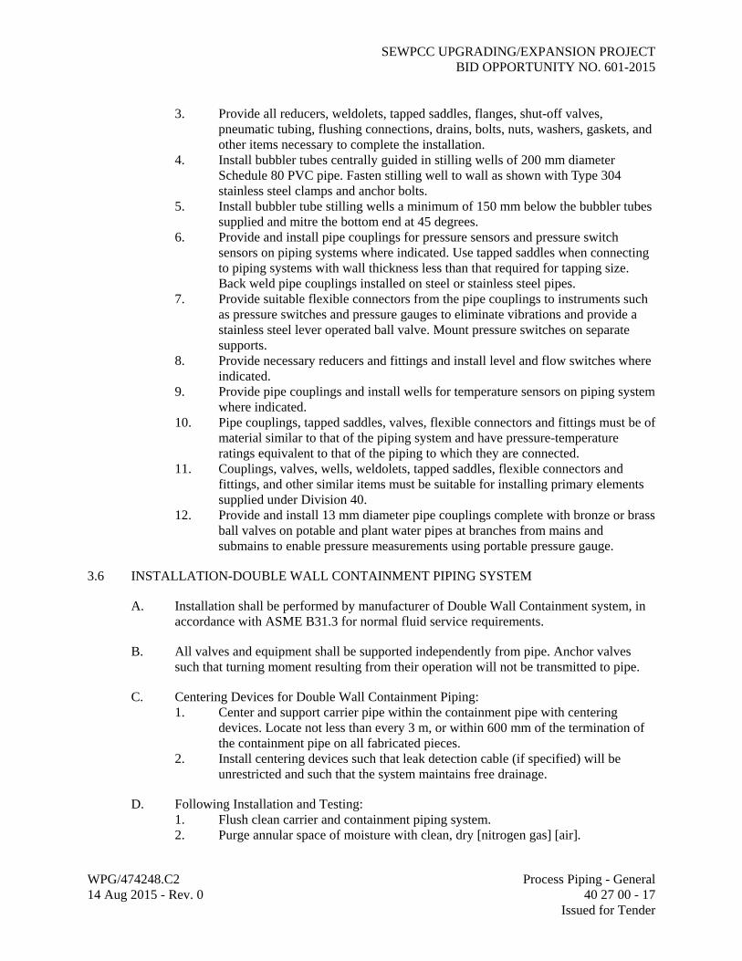
3. Provide all reducers, weldolets, tapped saddles, flanges, shut-off valves, pneumatic tubing, flushing connections, drains, bolts, nuts, washers, gaskets, and other items necessary to complete the installation.
4. Install bubbler tubes centrally guided in stilling wells of 200 mm diameter Schedule 80 PVC pipe. Fasten stilling well to wall as shown with Type 304 stainless steel clamps and anchor bolts.
5. Install bubbler tube stilling wells a minimum of 150 mm below the bubbler tubes supplied and mitre the bottom end at 45 degrees.
6. Provide and install pipe couplings for pressure sensors and pressure switch sensors on piping systems where indicated. Use tapped saddles when connecting to piping systems with wall thickness less than that required for tapping size. Back weld pipe couplings installed on steel or stainless steel pipes.
7. Provide suitable flexible connectors from the pipe couplings to instruments such as pressure switches and pressure gauges to eliminate vibrations and provide a stainless steel lever operated ball valve. Mount pressure switches on separate supports.
8. Provide necessary reducers and fittings and install level and flow switches where indicated.
9. Provide pipe couplings and install wells for temperature sensors on piping system where indicated.
10. Pipe couplings, tapped saddles, valves, flexible connectors and fittings must be of material similar to that of the piping system and have pressure-temperature ratings equivalent to that of the piping to which they are connected.
11. Couplings, valves, wells, weldolets, tapped saddles, flexible connectors and fittings, and other similar items must be suitable for installing primary elements supplied under Division 40.
12. Provide and install 13 mm diameter pipe couplings complete with bronze or brass ball valves on potable and plant water pipes at branches from mains and submains to enable pressure measurements using portable pressure gauge.
3.6 INSTALLATION-DOUBLE WALL CONTAINMENT PIPING SYSTEM
A. Installation shall be performed by manufacturer of Double Wall Containment system, in accordance with ASME B31.3 for normal fluid service requirements.
B. All valves and equipment shall be supported independently from pipe. Anchor valves such that turning moment resulting from their operation will not be transmitted to pipe.
C. Centering Devices for Double Wall Containment Piping: 1. Center and support carrier pipe within the containment pipe with centering
devices. Locate not less than every 3 m, or within 600 mm of the termination of the containment pipe on all fabricated pieces.
2. Install centering devices such that leak detection cable (if specified) will be unrestricted and such that the system maintains free drainage.
D. Following Installation and Testing: 1. Flush clean carrier and containment piping system. 2. Purge annular space of moisture with clean, dry [nitrogen gas] [air].

SEWPCC UPGRADING/EXPANSION PROJECT BID OPPORTUNITY NO. 601-2015
WPG/474248.C2 Process Piping - General 14 Aug 2015 - Rev. 0 40 27 00 - 18 Issued for Tender
3.7 LEAK DETECTION SYSTEM FOR DOUBLE WALL CONTAINMENT PIPING
A. Install in strict accordance with the system manufacturer's instructions and recommendations.
3.8 INSTALLATION-BURIED PIPE
A. Joints: 1. Dissimilar Buried Pipes:
a. Provide flexible mechanical compression joints for pressure pipe. b. Provide concrete closure collar for gravity and low pressure (maximum
70 kPa) piping or as shown. 2. Concrete Encased or Embedded Pipe: Do not encase joints in concrete unless
specifically shown.
B. Placement: 1. Keep trench dry until pipe laying and joining are completed. 2. Exercise care when lowering pipe into trench to prevent twisting or damage to
pipe. 3. Measure for grade at pipe invert, not at top of pipe. 4. Excavate trench bottom and sides of ample dimensions to permit visual
inspection and testing of entire flange, valve, or connection. 5. Prevent foreign material from entering pipe during placement. 6. Close and block open end of last laid pipe section when placement operations are
not in progress and at close of day's work. 7. Lay pipe upgrade with bell ends pointing in direction of laying. 8. Install closure sections and adapters for gravity piping at locations where pipe
laying changes direction. 9. Deflect pipe at joints for pipelines laid on a curve using unsymmetrical closure of
spigot into bell. If joint deflection of standard pipe lengths will not accommodate horizontal or vertical curves in alignment, provide: a. Shorter pipe lengths. b. Special mitered joints. c. Standard or special fabricated bends.
10. After joint has been made, check pipe alignment and grade. 11. Place sufficient pipe zone material to secure pipe from movement before next
joint is installed. 12. Prevent uplift and floating of pipe prior to backfilling.
C. PVC, CPVC, or HDPE Pipe Placement: 1. Lay pipe snaking from one side of trench to other. 2. Offset: As recommended by manufacturer for maximum temperature variation
between time of solvent welding and during operation. 3. Do not lay pipe when temperature is below 5 degrees C, or above 32 degrees C
when exposed to direct sunlight. 4. Shield ends to be joined from direct sunlight prior to and during the laying
operation.

SEWPCC UPGRADING/EXPANSION PROJECT BID OPPORTUNITY NO. 601-2015
WPG/474248.C2 Process Piping - General 14 Aug 2015 - Rev. 0 40 27 00 - 19 Issued for Tender
D. Tolerances: 1. Deflection From Horizontal Line: Maximum 50 mm. 2. Deflection From Vertical Grade: Maximum 6 mm. 3. Joint Deflection: Maximum of 75 percent of manufacturer's recommendation. 4. Horizontal position of pipe centerline on alignment around curves maximum
variation of 500 mm from position shown. 5. Pipe Cover: Minimum 1000 mm, unless otherwise shown.
3.9 INSTALLATION – CONCRETE ENCASED
A. Provide reinforced concrete pipe encasement where shown on Drawings and where otherwise required. Some piping may be required to be concrete encased for pipe strength requirements that are included in the Specifications. Piping under and within the influence of buildings, utility trenches, vaults, slabs and other structures shall be concrete encased. See details on Drawings for encasement requirements.
B. Where concrete encased piping crosses structure construction and expansion joints, provide flexible piping joints to coincide with structure joints to prevent excessive pipe stress and breakage.
3.10 THRUST RESTRAINT
A. Location: 1. Buried Piping: Where shown and where required to restrain force developed at
pipeline tees, plugs, caps, bends, and other locations where unbalanced forces exist due to hydrostatic testing and operating pressure.
2. Exposed Piping: At all joints in piping.
B. Thrust Ties: 1. Steel Pipe: Attach with fabricated lugs. 2. Ductile Iron Pipe: Attach with socket clamps against a grooved joint coupling or
flange. 3. Flanged Coupling Adapters: For exposed installations, install manufacturer's
anchor studs through the coupling sleeve.
C. Mechanical Joint Valve Restraint in Proprietary Restrained Joint Piping: Install pipe joint manufacturer's adapter gland follower and pipe end retainer, or thrust tie-rods and socket clamps.
D. Thrust Blocking: 1. Place between undisturbed ground and fitting to be anchored. 2. Quantity of Concrete: Sufficient to cover bearing area on pipe and provide
required soil bearing area as shown. 3. Place blocking so that pipe and fitting joints will be accessible for repairs. 4. Place concrete in accordance with Section 03 30 00, Cast-in-Place Concrete.
3.11 SLAB, FLOOR, WALL, AND ROOF PENETRATIONS
A. Application and Installation: As specified in Section 40 27 01, Process Piping Specialties.

SEWPCC UPGRADING/EXPANSION PROJECT BID OPPORTUNITY NO. 601-2015
WPG/474248.C2 Process Piping - General 14 Aug 2015 - Rev. 0 40 27 00 - 20 Issued for Tender
3.12 BRANCH CONNECTIONS
A. Do not install branch connections smaller than 13 mm nominal pipe size, including instrument connections, unless shown otherwise.
B. When line of lower pressure connects to a line of higher pressure, requirements of Piping Data Sheet for higher pressure rating prevails up to and including the first block valve in the line carrying the lower pressure, unless otherwise shown.
C. Threaded Pipe Tap Connections: 1. Ductile Iron Piping: Connect only with service saddle or at a tapping boss of a
fitting, valve body, or equipment casting. 2. Welded Steel or Alloy Piping: Connect only with welded threadolet or half-
coupling as specified on Piping Data Sheet. 3. Limitations: Threaded taps in pipe barrel are unacceptable.
3.13 VENTS AND DRAINS
A. Vents and drains at high and low points in piping required for completed system may or may not be shown on Drawings. Install vents on high points and drains on low points of pipelines at all low and high point locations whether or not shown on Drawings.
3.14 CLEANING
A. Following assembly and testing, and prior to disinfection and final acceptance, flush pipelines (except as stated below) with water at 0.8 m/s minimum flushing velocity until foreign matter is removed.
B. Blow clean of loose debris plant process air, natural gas, and instrument air-lines with compressed air at 138 kPa (20 psi); do not flush with water.
C. Immediately after cleaning pipes, dry to minus 5 C dew point with dry compressed instrument air or compressed commercial grade nitrogen.
D. If impractical to flush large diameter pipe at 0.8 m/s or blow at 1200 m/min velocity, clean in-place from inside by brushing and sweeping, then flush or blow line at lower velocity.
E. Insert cone strainers in flushing connections to attached equipment and leave in-place until cleaning is complete.
F. Remove accumulated debris through drains 50 mm and larger or by removing spools and valves from piping.
3.15 DISINFECTION
A. In accordance with AWWA C651.
SEWPCC UPGRADING/EXPANSION PROJECT BID OPPORTUNITY NO. 601-2015
WPG/474248.C2 Process Piping - General 14 Aug 2015 - Rev. 0 40 27 00 - 21 Issued for Tender
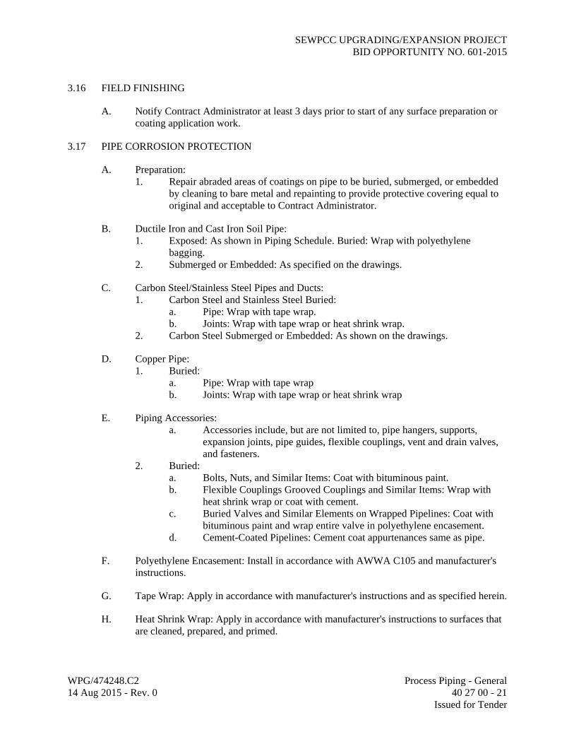
3.16 FIELD FINISHING
A. Notify Contract Administrator at least 3 days prior to start of any surface preparation or coating application work.
3.17 PIPE CORROSION PROTECTION
A. Preparation: 1. Repair abraded areas of coatings on pipe to be buried, submerged, or embedded
by cleaning to bare metal and repainting to provide protective covering equal to original and acceptable to Contract Administrator.
B. Ductile Iron and Cast Iron Soil Pipe: 1. Exposed: As shown in Piping Schedule. Buried: Wrap with polyethylene
bagging. 2. Submerged or Embedded: As specified on the drawings.
C. Carbon Steel/Stainless Steel Pipes and Ducts: 1. Carbon Steel and Stainless Steel Buried:
a. Pipe: Wrap with tape wrap. b. Joints: Wrap with tape wrap or heat shrink wrap.
2. Carbon Steel Submerged or Embedded: As shown on the drawings.
D. Copper Pipe: 1. Buried:
a. Pipe: Wrap with tape wrap b. Joints: Wrap with tape wrap or heat shrink wrap
E. Piping Accessories: a. Accessories include, but are not limited to, pipe hangers, supports,
expansion joints, pipe guides, flexible couplings, vent and drain valves, and fasteners.
2. Buried: a. Bolts, Nuts, and Similar Items: Coat with bituminous paint. b. Flexible Couplings Grooved Couplings and Similar Items: Wrap with
heat shrink wrap or coat with cement. c. Buried Valves and Similar Elements on Wrapped Pipelines: Coat with
bituminous paint and wrap entire valve in polyethylene encasement. d. Cement-Coated Pipelines: Cement coat appurtenances same as pipe.
F. Polyethylene Encasement: Install in accordance with AWWA C105 and manufacturer's instructions.
G. Tape Wrap: Apply in accordance with manufacturer's instructions and as specified herein.
H. Heat Shrink Wrap: Apply in accordance with manufacturer's instructions to surfaces that are cleaned, prepared, and primed.
SEWPCC UPGRADING/EXPANSION PROJECT BID OPPORTUNITY NO. 601-2015
WPG/474248.C2 Process Piping - General 14 Aug 2015 - Rev. 0 40 27 00 - 22 Issued for Tender
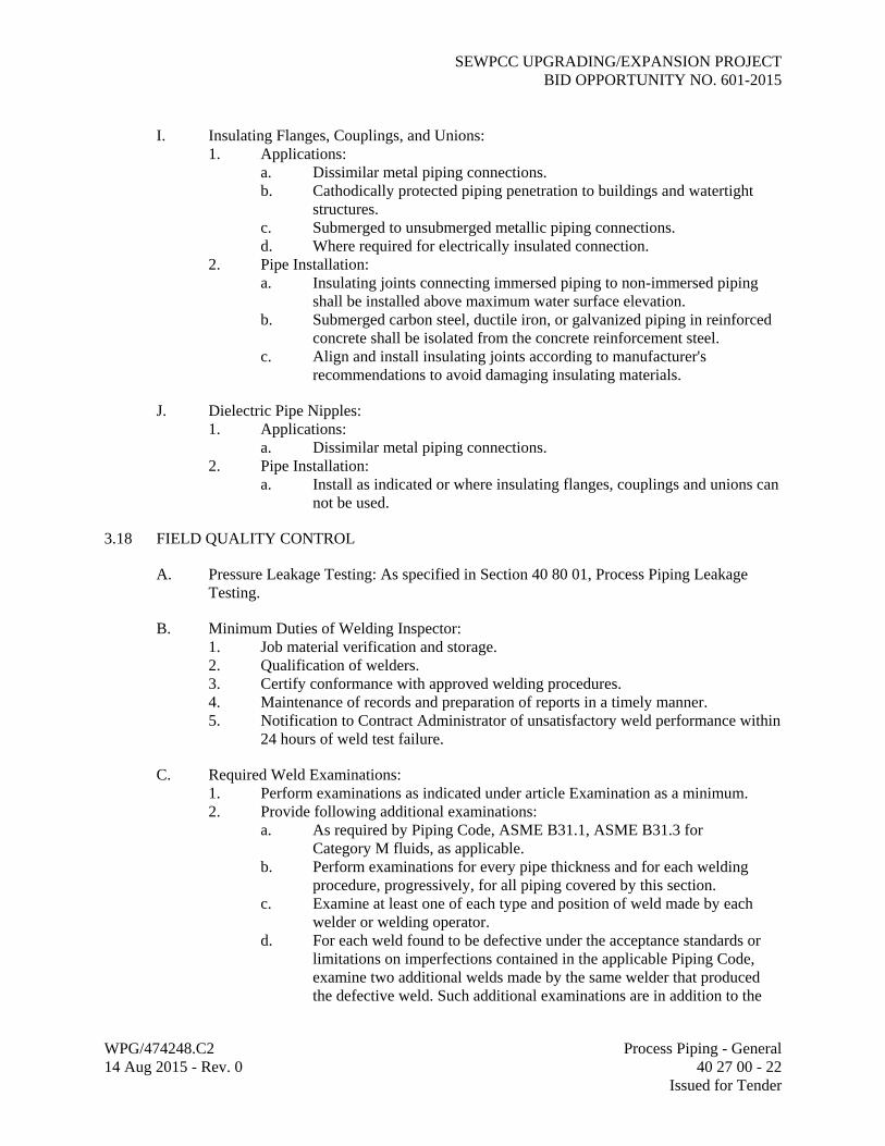
I. Insulating Flanges, Couplings, and Unions: 1. Applications:
a. Dissimilar metal piping connections. b. Cathodically protected piping penetration to buildings and watertight
structures. c. Submerged to unsubmerged metallic piping connections. d. Where required for electrically insulated connection.
2. Pipe Installation: a. Insulating joints connecting immersed piping to non-immersed piping
shall be installed above maximum water surface elevation. b. Submerged carbon steel, ductile iron, or galvanized piping in reinforced
concrete shall be isolated from the concrete reinforcement steel. c. Align and install insulating joints according to manufacturer's
recommendations to avoid damaging insulating materials.
J. Dielectric Pipe Nipples: 1. Applications:
a. Dissimilar metal piping connections. 2. Pipe Installation:
a. Install as indicated or where insulating flanges, couplings and unions can not be used.
3.18 FIELD QUALITY CONTROL
A. Pressure Leakage Testing: As specified in Section 40 80 01, Process Piping Leakage Testing.
B. Minimum Duties of Welding Inspector: 1. Job material verification and storage. 2. Qualification of welders. 3. Certify conformance with approved welding procedures. 4. Maintenance of records and preparation of reports in a timely manner. 5. Notification to Contract Administrator of unsatisfactory weld performance within
24 hours of weld test failure.
C. Required Weld Examinations: 1. Perform examinations as indicated under article Examination as a minimum. 2. Provide following additional examinations:
a. As required by Piping Code, ASME B31.1, ASME B31.3 for Category M fluids, as applicable.
b. Perform examinations for every pipe thickness and for each welding procedure, progressively, for all piping covered by this section.
c. Examine at least one of each type and position of weld made by each welder or welding operator.
d. For each weld found to be defective under the acceptance standards or limitations on imperfections contained in the applicable Piping Code, examine two additional welds made by the same welder that produced the defective weld. Such additional examinations are in addition to the

SEWPCC UPGRADING/EXPANSION PROJECT BID OPPORTUNITY NO. 601-2015
WPG/474248.C2 Process Piping - General 14 Aug 2015 - Rev. 0 40 27 00 - 23 Issued for Tender
minimum required above. Examine, progressively, two additional welds for each tracer examination found to be unsatisfactory.
D. Test the leak detection system in accordance with the system manufacturer's instructions and recommendations to verify proper operation.
3.19 SUPPLEMENTS
A. Process Piping Schedule.
B. Data Sheets.
Number Title
-01 Cement-Mortar Lined Ductile Iron Pipe and Fittings
-03 Carbon Steel Pipe and Fittings – General Service
-08 Stainless Steel Pipe and Fittings – General Service
-08A Stainless Steel Pipe and Fittings – Process Air Service
-13 Copper and Copper Alloy Pipe, Tubing, and Fittings
END OF SECTION
SEWPCC UPGRADING/EXPANSION PROJECTBID OPPORTUNITY NO. 601-2015
Service Abbrev.[Note 1] Service Description
Size(s)(mm)
[Note 2]Exposure[Note 3]
Piping Material[Note 4]
PipeSpecification
Code
Data Sheet Specification
Section
Thickness, Class, or Schedule[Note 5]
Joints[Note 6]
Design Maximum Operating Pressure
(kPag)
Design Temp. Range(deg C)
Test Pressure
(kPag)and Type[Note 7]
ASME Code and Fluid Service
Category
Lining / Coating[Note 8]
Remarks[Note 9]
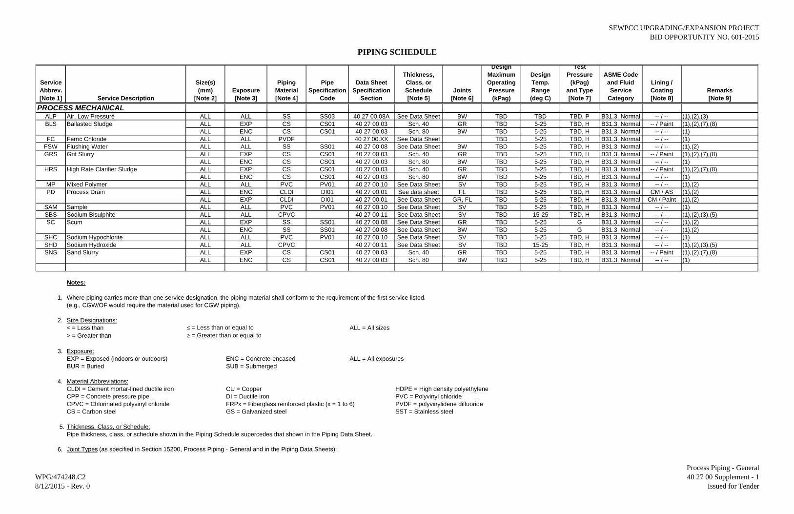
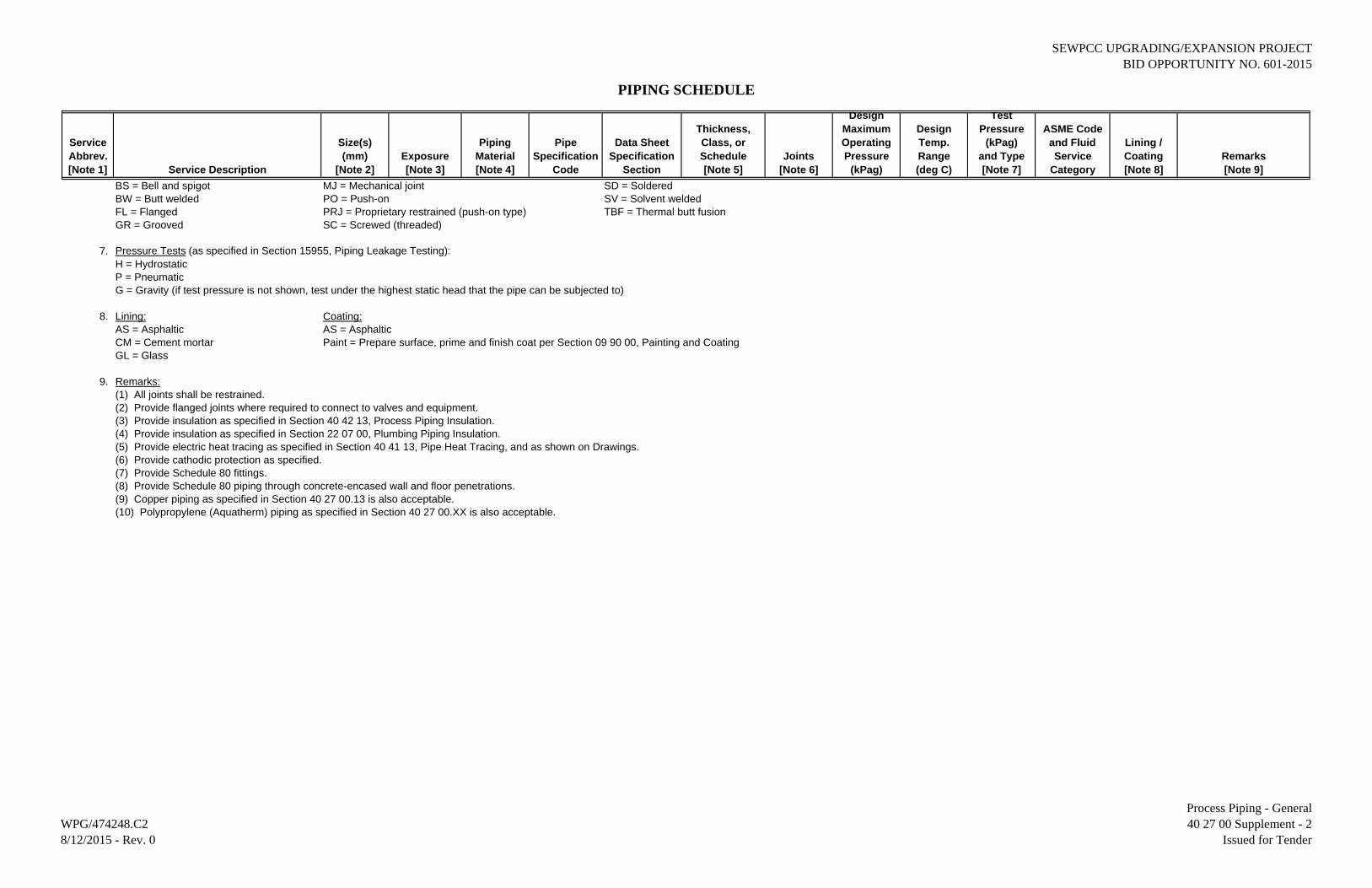
PROCESS MECHANICALALP Air, Low Pressure ALL ALL SS SS03 40 27 00.08A See Data Sheet BW TBD TBD TBD, P B31.3, Normal -- / -- (1),(2),(3)BLS Ballasted Sludge ALL EXP CS CS01 40 27 00.03 Sch. 40 GR TBD 5-25 TBD, H B31.3, Normal -- / Paint (1),(2),(7),(8)
ALL ENC CS CS01 40 27 00.03 Sch. 80 BW TBD 5-25 TBD, H B31.3, Normal -- / -- (1)FC Ferric Chloride ALL ALL PVDF 40 27 00.XX See Data Sheet TBD 5-25 TBD, H B31.3, Normal -- / -- (1)
FSW Flushing Water ALL ALL SS SS01 40 27 00.08 See Data Sheet BW TBD 5-25 TBD, H B31.3, Normal -- / -- (1),(2)GRS Grit Slurry ALL EXP CS CS01 40 27 00.03 Sch. 40 GR TBD 5-25 TBD, H B31.3, Normal -- / Paint (1),(2),(7),(8)
ALL ENC CS CS01 40 27 00.03 Sch. 80 BW TBD 5-25 TBD, H B31.3, Normal -- / -- (1)HRS High Rate Clarifier Sludge ALL EXP CS CS01 40 27 00.03 Sch. 40 GR TBD 5-25 TBD, H B31.3, Normal -- / Paint (1),(2),(7),(8)
ALL ENC CS CS01 40 27 00.03 Sch. 80 BW TBD 5-25 TBD, H B31.3, Normal -- / -- (1)MP Mixed Polymer ALL ALL PVC PV01 40 27 00.10 See Data Sheet SV TBD 5-25 TBD, H B31.3, Normal -- / -- (1),(2)PD Process Drain ALL ENC CLDI DI01 40 27 00.01 See data sheet FL TBD 5-25 TBD, H B31.3, Normal CM / AS (1),(2)
ALL EXP CLDI DI01 40 27 00.01 See Data Sheet GR, FL TBD 5-25 TBD, H B31.3, Normal CM / Paint (1),(2)SAM Sample ALL ALL PVC PV01 40 27 00.10 See Data Sheet SV TBD 5-25 TBD, H B31.3, Normal -- / -- (1)SBS Sodium Bisulphite ALL ALL CPVC 40 27 00.11 See Data Sheet SV TBD 15-25 TBD, H B31.3, Normal -- / -- (1),(2),(3),(5)SC Scum ALL EXP SS SS01 40 27 00.08 See Data Sheet GR TBD 5-25 G B31.3, Normal -- / -- (1),(2)
ALL ENC SS SS01 40 27 00.08 See Data Sheet BW TBD 5-25 G B31.3, Normal -- / -- (1),(2)SHC Sodium Hypochlorite ALL ALL PVC PV01 40 27 00.10 See Data Sheet SV TBD 5-25 TBD, H B31.3, Normal -- / -- (1)SHD Sodium Hydroxide ALL ALL CPVC 40 27 00.11 See Data Sheet SV TBD 15-25 TBD, H B31.3, Normal -- / -- (1),(2),(3),(5)SNS Sand Slurry ALL EXP CS CS01 40 27 00.03 Sch. 40 GR TBD 5-25 TBD, H B31.3, Normal -- / Paint (1),(2),(7),(8)
ALL ENC CS CS01 40 27 00.03 Sch. 80 BW TBD 5-25 TBD, H B31.3, Normal -- / -- (1)
Notes:
1. Where piping carries more than one service designation, the piping material shall conform to the requirement of the first service listed.(e.g., CGW/OF would require the material used for CGW piping).
2. Size Designations:< = Less than ≤ = Less than or equal to ALL = All sizes> = Greater than ≥ = Greater than or equal to
3. Exposure:EXP = Exposed (indoors or outdoors) ENC = Concrete-encased ALL = All exposuresBUR = Buried SUB = Submerged
4. Material Abbreviations:CLDI = Cement mortar-lined ductile iron CU = Copper HDPE = High density polyethyleneCPP = Concrete pressure pipe DI = Ductile iron PVC = Polyvinyl chlorideCPVC = Chlorinated polyvinyl chloride FRPx = Fiberglass reinforced plastic (x = 1 to 6) PVDF = polyvinylidene difluorideCS = Carbon steel GS = Galvanized steel SST = Stainless steel
5. Thickness, Class, or Schedule:Pipe thickness, class, or schedule shown in the Piping Schedule supercedes that shown in the Piping Data Sheet.
6. Joint Types (as specified in Section 15200, Process Piping - General and in the Piping Data Sheets):
PIPING SCHEDULE
WPG/474248.C28/12/2015 - Rev. 0
Process Piping - General40 27 00 Supplement - 1
Issued for Tender
SEWPCC UPGRADING/EXPANSION PROJECTBID OPPORTUNITY NO. 601-2015
Service Abbrev.[Note 1] Service Description
Size(s)(mm)
[Note 2]Exposure[Note 3]
Piping Material[Note 4]
PipeSpecification
Code
Data Sheet Specification
Section
Thickness, Class, or Schedule[Note 5]
Joints[Note 6]
Design Maximum Operating Pressure
(kPag)
Design Temp. Range(deg C)
Test Pressure
(kPag)and Type[Note 7]
ASME Code and Fluid Service
Category
Lining / Coating[Note 8]
Remarks[Note 9]
PIPING SCHEDULE
BS = Bell and spigot MJ = Mechanical joint SD = SolderedBW = Butt welded PO = Push-on SV = Solvent weldedFL = Flanged PRJ = Proprietary restrained (push-on type) TBF = Thermal butt fusionGR = Grooved SC = Screwed (threaded)
7. Pressure Tests (as specified in Section 15955, Piping Leakage Testing):H = HydrostaticP = PneumaticG = Gravity (if test pressure is not shown, test under the highest static head that the pipe can be subjected to)
8. Lining: Coating:AS = Asphaltic AS = AsphalticCM = Cement mortar Paint = Prepare surface, prime and finish coat per Section 09 90 00, Painting and CoatingGL = Glass
9. Remarks:(1) All joints shall be restrained.(2) Provide flanged joints where required to connect to valves and equipment.(3) Provide insulation as specified in Section 40 42 13, Process Piping Insulation.(4) Provide insulation as specified in Section 22 07 00, Plumbing Piping Insulation.(5) Provide electric heat tracing as specified in Section 40 41 13, Pipe Heat Tracing, and as shown on Drawings.(6) Provide cathodic protection as specified.(7) Provide Schedule 80 fittings.(8) Provide Schedule 80 piping through concrete-encased wall and floor penetrations.(9) Copper piping as specified in Section 40 27 00.13 is also acceptable.(10) Polypropylene (Aquatherm) piping as specified in Section 40 27 00.XX is also acceptable.
WPG/474248.C28/12/2015 - Rev. 0
Process Piping - General40 27 00 Supplement - 2
Issued for Tender

SEWPCC UPGRADING/EXPANSION PROJECT BID OPPORTUNITY NO. 601-2015
WPG/474248.C2 Data Sheet – Cement-Mortar Lined 12 Aug 2015 - Rev. 0 Ductile Iron Pipe and Fittings 40 27 00.01 - 1 Issued for Tender
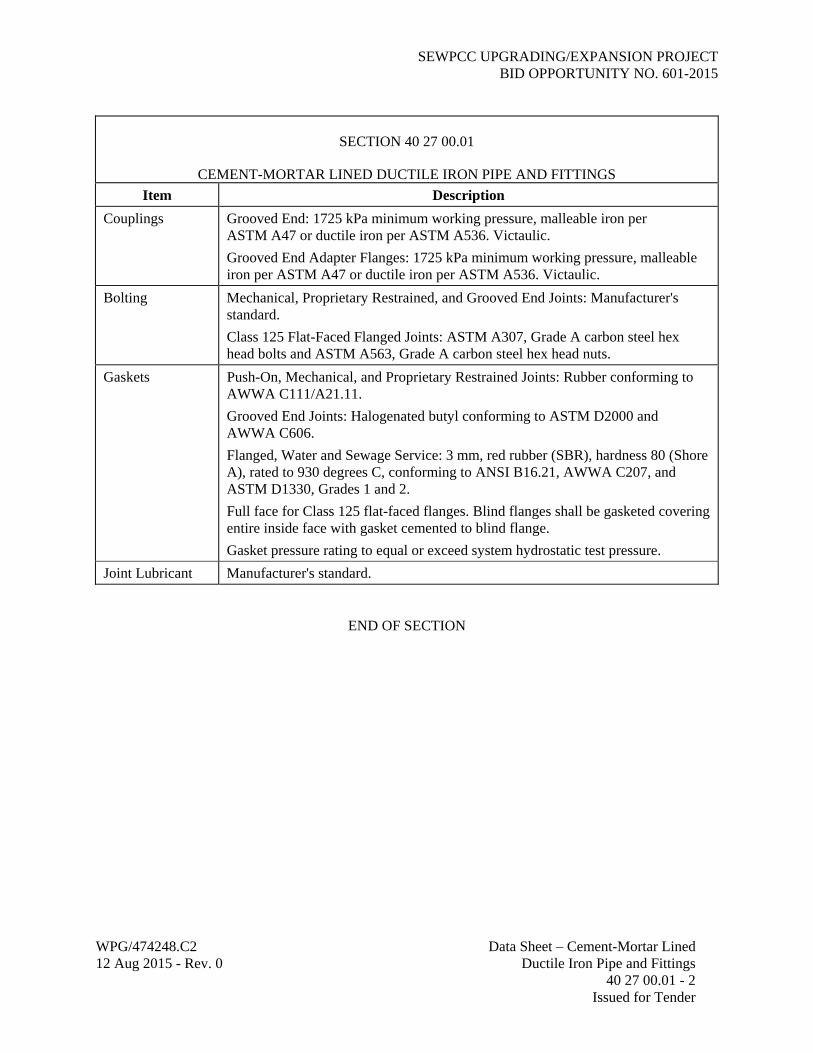
SECTION 40 27 00.01
CEMENT-MORTAR LINED DUCTILE IRON PIPE AND FITTINGS
Item Description
Pipe Buried Service Using Push-On, Mechanical, or Proprietary Restrained Joints: AWWA C111/A21.11, and AWWA C151/A21.51, pressure class conforming to Tables 5 and 7 for Type 4 trench, 1725 kPa minimum working pressure. Follower glands shall be ductile iron.
Exposed Pipe Using Grooved End and Flanged Joints: AWWA C115/A21.15, thickness Class 53 minimum, 1725 kPa minimum working pressure.
Lining Cement-Mortar: AWWA C104/A21.4.
Fittings Lined and coated same as pipe.
Push-On: AWWA C110/A21.10 and C111/A21.11, gray or ductile iron, 1725 kPa minimum working pressure. American Cast Iron Pipe Co., Fastite Joint; U.S. Pipe and Foundry, Tyton Joint.
Mechanical: AWWA C110/A21.10, C111/A21.11, and C153/A21.53 gray or ductile iron, 1725 kPa minimum working pressure. Follower glands shall be ductile iron.
Proprietary Restrained: AWWA C111/A21.11 and C153/A21.53, ductile iron, 1725 kPa minimum working pressure. Clow Corp., Super-Lock Joint; American Cast Iron Pipe Co., Flex-Ring or Lok-Ring Joint; U.S. Pipe, TR Flex.
Grooved End: AWWA C606 and C110/A21.10, ductile iron, 1725 kPa minimum working pressure. Victaulic.
Flanged: AWWA C110/A21.10, ductile iron, faced and drilled to ASME B16.1 and MSS SP-6, Class 125 flat face. Gray cast iron will not be allowed.
Joints Push-On: 1725 kPa minimum working pressure, AWWA C110/A21.10 and C111/A21.11. American Cast Iron Pipe Co., Fastite Joint; U.S. Pipe and Foundry, Tyton Joint.
Mechanical: 1725 kPa minimum working pressure.
Proprietary Restrained: 1050 kPa minimum working pressure. Clow Corp., Super-Lock; American Cast Iron Pipe Co., Flex-Ring or Lok-Ring; U.S. Pipe, TR Flex.
Grooved End: Rigid type radius cut conforming to AWWA C606, 1700 kPa minimum working pressure. Victaulic.
Flanged: Class 125 flat face, ductile iron, threaded conforming to AWWA C115/A21.15. Gray cast iron will not be allowed.
Branch connections 80 mm and smaller shall be made with service saddles as specified in Section 15205, Process Piping Specialties.
SEWPCC UPGRADING/EXPANSION PROJECT BID OPPORTUNITY NO. 601-2015
WPG/474248.C2 Data Sheet – Cement-Mortar Lined 12 Aug 2015 - Rev. 0 Ductile Iron Pipe and Fittings 40 27 00.01 - 2 Issued for Tender
SECTION 40 27 00.01
CEMENT-MORTAR LINED DUCTILE IRON PIPE AND FITTINGS
Item Description
Couplings Grooved End: 1725 kPa minimum working pressure, malleable iron per ASTM A47 or ductile iron per ASTM A536. Victaulic.
Grooved End Adapter Flanges: 1725 kPa minimum working pressure, malleable iron per ASTM A47 or ductile iron per ASTM A536. Victaulic.
Bolting Mechanical, Proprietary Restrained, and Grooved End Joints: Manufacturer's standard.
Class 125 Flat-Faced Flanged Joints: ASTM A307, Grade A carbon steel hex head bolts and ASTM A563, Grade A carbon steel hex head nuts.
Gaskets Push-On, Mechanical, and Proprietary Restrained Joints: Rubber conforming to AWWA C111/A21.11.
Grooved End Joints: Halogenated butyl conforming to ASTM D2000 and AWWA C606.
Flanged, Water and Sewage Service: 3 mm, red rubber (SBR), hardness 80 (Shore A), rated to 930 degrees C, conforming to ANSI B16.21, AWWA C207, and ASTM D1330, Grades 1 and 2.
Full face for Class 125 flat-faced flanges. Blind flanges shall be gasketed covering entire inside face with gasket cemented to blind flange.
Gasket pressure rating to equal or exceed system hydrostatic test pressure.
Joint Lubricant Manufacturer's standard.
END OF SECTION

SEWPCC UPGRADING/EXPANSION PROJECT BID OPPORTUNITY NO. 601-2015
WPG/474248.C2 Carbon Steel Pipe and Fittings - 12 Aug 2015 - Rev. 0 General Service 40 27 00.03 Data Sheet - 1 Issued for Tender
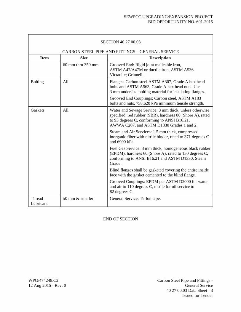
SECTION 40 27 00.03
CARBON STEEL PIPE AND FITTINGS – GENERAL SERVICE
Item Size Description
Pipe 600 mm & smaller Black carbon steel, ASTM A106/A106M Grade B seamless, or ASTM A53/A53M Grade B seamless or ERW, conforming to ASME B36.10M.
750 mm & larger Carbon steel, ASTM A283/A283M Grade C, or ASTM A285/A285M Grade C, sheet or coil, fabricated in accordance with AWWA C200 and ASTM A134, straight or spiral seam, conforming to ASME B36.10M.
Screwed:
50 mm & smaller Schedule 80.
Welded:
65 mm to 250 mm Schedule 40.
300 mm to 400 mm Schedule 30.
450 mm to 600 mm Schedule 20.
650 mm & larger Schedule 20, min. 12.7 mm (1/2 in) wall thickness.
Grooved:
60 mm to 150 mm Schedule 40.
200 mm to 300 mm Schedule 30.
350 mm Standard weight, min. 9.5 mm (3/8 in) wall thickness.
Joints 50 mm & smaller Threaded, or grooved end meeting the requirements of AWWA C606; flanged at valves and equipment where required.
60 mm & larger Butt-welded, or grooved end meeting the requirements of AWWA C606; flanged at valves and equipment where required.
Fittings 50 mm & smaller Threaded: Malleable iron, ASTM A197/A197M or ASTM A47/A47M, dimensions in accordance with ANSI B16.3 Class 150 or Class 300. Fire sprinkler fittings to be UL listed.
350 mm & smaller Grooved End: Malleable iron, ASTM A47/A47M, or ductile iron, ASTM A536, grooved ends to accept couplings without field preparation. Victaulic; Grinnell.
65 mm to 600 mm Butt-welded: Wrought carbon steel butt-welding, ASTM A234/A234M Grade WPB, meeting the requirements of ASME B16.9; fitting wall thickness to match adjoining pipe; long radius elbows unless shown otherwise.

SEWPCC UPGRADING/EXPANSION PROJECT BID OPPORTUNITY NO. 601-2015
WPG/474248.C2 Carbon Steel Pipe and Fittings - 12 Aug 2015 - Rev. 0 General Service 40 27 00.03 Data Sheet - 2 Issued for Tender
SECTION 40 27 00.03
CARBON STEEL PIPE AND FITTINGS – GENERAL SERVICE
Item Size Description
650 mm & larger Butt-welded: Shop-fabricated from carbon steel pipe as specified above in accordance with AWWA C208; fitting wall thickness to match adjoining pipe; elbows to have 22.5-degree maximum miter deflection angle, minimum of three sections for 45-degree elbows, minimum of five sections for 90-degree elbows; wyes, tees, crosses, and outlets to be reinforced in accordance with AWWA M-11.
Branch Connections
50 mm & smaller Threaded or grooved end straight or reducing tees in conformance with Fittings specified above.
65 mm & larger Butt-welding or grooved end straight or reducing tees in conformance with Fittings specified above.
Flanges 50 mm & smaller Threaded Systems: Forged carbon steel, ASTM A105/A105M, Grade II, ASME B16.5 Class 150 or Class 300, socket-weld or threaded, 1.5 mm raised face.
350 mm & smaller Grooved End Systems: Grooved end adapter flange, malleable iron ASTM A47/A47M or ductile iron ASTM A536. Victaulic; Grinnell.
65 mm to 600 mm Butt-Welded Systems: Forged carbon steel, ASTM A105/A105M, ASME B16.5 Class 150 or Class 300, slip-on or welding neck, 1.5 mm raised face; weld neck bore to match pipe internal diameter. Use weld neck flanges when abutting butt-weld fittings. Flat face Class 150 for connection to ductile/cast iron Class 125 flanges.
650 mm & larger Butt-Welded Systems: Carbon steel, AWWA C207 Class D or Class E, hub or ring type, flat face, drilling to ASME B16.1 Class 125; Class F, hub or ring type, flat face, drilling to ASME B16.1 Class 250.
Unions 50 mm & smaller Threaded malleable iron, ASTM A197/A197M or A47/A47M, meeting the requirements of ANSI B16.3 Class 150 or Class 300.
Couplings 50 mm & smaller Screwed End: Malleable iron, ASTM A197/A197M or A47/A47M.
SEWPCC UPGRADING/EXPANSION PROJECT BID OPPORTUNITY NO. 601-2015
WPG/474248.C2 Carbon Steel Pipe and Fittings - 12 Aug 2015 - Rev. 0 General Service 40 27 00.03 Data Sheet - 3 Issued for Tender
SECTION 40 27 00.03
CARBON STEEL PIPE AND FITTINGS – GENERAL SERVICE
Item Size Description
60 mm thru 350 mm Grooved End: Rigid joint malleable iron, ASTM A47/A47M or ductile iron, ASTM A536. Victaulic; Grinnell.
Bolting All Flanges: Carbon steel ASTM A307, Grade A hex head bolts and ASTM A563, Grade A hex head nuts. Use 3 mm undersize bolting material for insulating flanges.
Grooved End Couplings: Carbon steel, ASTM A183 bolts and nuts, 758,620 kPa minimum tensile strength.
Gaskets All Water and Sewage Service: 3 mm thick, unless otherwise specified, red rubber (SBR), hardness 80 (Shore A), rated to 93 degrees C, conforming to ANSI B16.21, AWWA C207, and ASTM D1330 Grades 1 and 2.
Steam and Air Services: 1.5 mm thick, compressed inorganic fiber with nitrile binder, rated to 371 degrees C and 6900 kPa.
Fuel Gas Service: 3 mm thick, homogeneous black rubber (EPDM), hardness 60 (Shore A), rated to 150 degrees C, conforming to ANSI B16.21 and ASTM D1330, Steam Grade.
Blind flanges shall be gasketed covering the entire inside face with the gasket cemented to the blind flange.
Grooved Couplings: EPDM per ASTM D2000 for water and air to 110 degrees C, nitrile for oil service to 82 degrees C.
Thread Lubricant
50 mm & smaller General Service: Teflon tape.
END OF SECTION
SEWPCC UPGRADING/EXPANSION PROJECT BID OPPORTUNITY NO. 601-2015
WPG/474248.C2 Stainless Steel Pipe and Fittings 12 Aug 2015 - Rev. 0 General Service 40 27 00.08 Data Sheet - 1 Issued for Tender
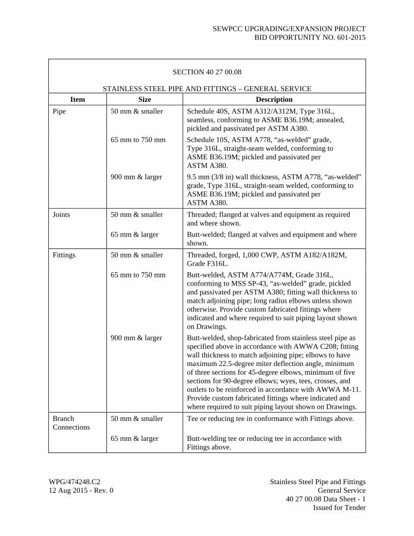
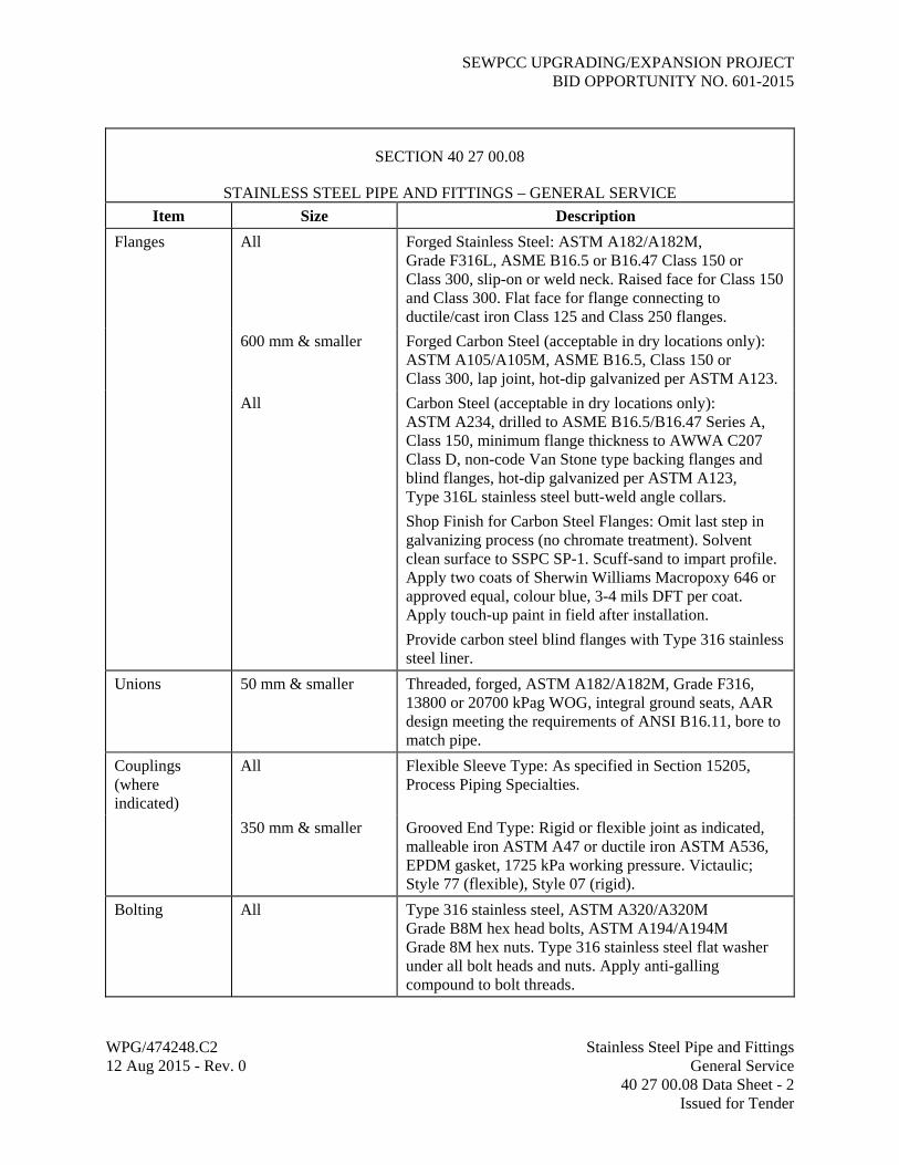
SECTION 40 27 00.08
STAINLESS STEEL PIPE AND FITTINGS – GENERAL SERVICE
Item Size Description
Pipe 50 mm & smaller Schedule 40S, ASTM A312/A312M, Type 316L, seamless, conforming to ASME B36.19M; annealed, pickled and passivated per ASTM A380.
65 mm to 750 mm Schedule 10S, ASTM A778, “as-welded” grade, Type 316L, straight-seam welded, conforming to ASME B36.19M; pickled and passivated per ASTM A380.
900 mm & larger 9.5 mm (3/8 in) wall thickness, ASTM A778, “as-welded” grade, Type 316L, straight-seam welded, conforming to ASME B36.19M; pickled and passivated per ASTM A380.
Joints 50 mm & smaller Threaded; flanged at valves and equipment as required and where shown.
65 mm & larger Butt-welded; flanged at valves and equipment and where shown.
Fittings 50 mm & smaller Threaded, forged, 1,000 CWP, ASTM A182/A182M, Grade F316L.
65 mm to 750 mm Butt-welded, ASTM A774/A774M, Grade 316L, conforming to MSS SP-43, “as-welded” grade, pickled and passivated per ASTM A380; fitting wall thickness to match adjoining pipe; long radius elbows unless shown otherwise. Provide custom fabricated fittings where indicated and where required to suit piping layout shown on Drawings.
900 mm & larger Butt-welded, shop-fabricated from stainless steel pipe as specified above in accordance with AWWA C208; fitting wall thickness to match adjoining pipe; elbows to have maximum 22.5-degree miter deflection angle, minimum of three sections for 45-degree elbows, minimum of five sections for 90-degree elbows; wyes, tees, crosses, and outlets to be reinforced in accordance with AWWA M-11. Provide custom fabricated fittings where indicated and where required to suit piping layout shown on Drawings.
Branch Connections
50 mm & smaller Tee or reducing tee in conformance with Fittings above.
65 mm & larger Butt-welding tee or reducing tee in accordance with Fittings above.
SEWPCC UPGRADING/EXPANSION PROJECT BID OPPORTUNITY NO. 601-2015
WPG/474248.C2 Stainless Steel Pipe and Fittings 12 Aug 2015 - Rev. 0 General Service 40 27 00.08 Data Sheet - 2 Issued for Tender
SECTION 40 27 00.08
STAINLESS STEEL PIPE AND FITTINGS – GENERAL SERVICE
Item Size Description
Flanges All Forged Stainless Steel: ASTM A182/A182M, Grade F316L, ASME B16.5 or B16.47 Class 150 or Class 300, slip-on or weld neck. Raised face for Class 150 and Class 300. Flat face for flange connecting to ductile/cast iron Class 125 and Class 250 flanges.
600 mm & smaller Forged Carbon Steel (acceptable in dry locations only): ASTM A105/A105M, ASME B16.5, Class 150 or Class 300, lap joint, hot-dip galvanized per ASTM A123.
All Carbon Steel (acceptable in dry locations only): ASTM A234, drilled to ASME B16.5/B16.47 Series A, Class 150, minimum flange thickness to AWWA C207 Class D, non-code Van Stone type backing flanges and blind flanges, hot-dip galvanized per ASTM A123, Type 316L stainless steel butt-weld angle collars.
Shop Finish for Carbon Steel Flanges: Omit last step in galvanizing process (no chromate treatment). Solvent clean surface to SSPC SP-1. Scuff-sand to impart profile. Apply two coats of Sherwin Williams Macropoxy 646 or approved equal, colour blue, 3-4 mils DFT per coat. Apply touch-up paint in field after installation.
Provide carbon steel blind flanges with Type 316 stainless steel liner.
Unions 50 mm & smaller Threaded, forged, ASTM A182/A182M, Grade F316, 13800 or 20700 kPag WOG, integral ground seats, AAR design meeting the requirements of ANSI B16.11, bore to match pipe.
Couplings (where indicated)
All Flexible Sleeve Type: As specified in Section 15205, Process Piping Specialties.
350 mm & smaller Grooved End Type: Rigid or flexible joint as indicated, malleable iron ASTM A47 or ductile iron ASTM A536, EPDM gasket, 1725 kPa working pressure. Victaulic; Style 77 (flexible), Style 07 (rigid).
Bolting All Type 316 stainless steel, ASTM A320/A320M Grade B8M hex head bolts, ASTM A194/A194M Grade 8M hex nuts. Type 316 stainless steel flat washer under all bolt heads and nuts. Apply anti-galling compound to bolt threads.

SEWPCC UPGRADING/EXPANSION PROJECT BID OPPORTUNITY NO. 601-2015
WPG/474248.C2 Stainless Steel Pipe and Fittings 12 Aug 2015 - Rev. 0 General Service 40 27 00.08 Data Sheet - 3 Issued for Tender
SECTION 40 27 00.08
STAINLESS STEEL PIPE AND FITTINGS – GENERAL SERVICE
Item Size Description
Gaskets All Flanges Sewage Service: 3 mm thick unless otherwise specified, red rubber (SBR), hardness 80 (Shore A), rated to 93 degrees C, conforming to ANSI B16.21, AWWA C207, and ASTM D1330, Grades 1 and 2.
Water Service: 3 mm thick unless otherwise specified, Santoprene thermoplastic or approved equal, NSF 61, hardness 59 (Shore A), rated to 93 degrees C, conforming to ANSI B16.21, AWWA C207, and ASTM D1330.
Blind flanges shall be gasketed covering entire inside face with gasket cemented to blind flange.
Thread Lubricant
50 mm & smaller Teflon tape.
END OF SECTION

SEWPCC UPGRADING/EXPANSION PROJECT BID OPPORTUNITY NO. 601-2015
WPG/474248.C2 Stainless Steel Pipe and Fittings 12 Aug 2015 - Rev. 0 Process Air Service 40 27 00.08A Data Sheet - 1 Issued for Tender
SECTION 40 27 00.08A
STAINLESS STEEL PIPE AND FITTINGS – PROCESS AIR SERVICE
Item Size Description
Pipe 50 mm & smaller Schedule 40S, ASTM A312/A312M, Type 316L, seamless, conforming to ASME B36.19M; annealed, pickled, and passivated per ASTM A380.
65 mm & larger Exposed/Submerged: Schedule 10S, ASTM A778, “as-welded” grade, Type 316L, straight-seam welded, conforming to ASME B36.19M; pickled and passivated per ASTM A380; minimum 7.92 mm (0.312 in) wall thickness for pipe sizes larger than 750 mm.
For pipe sizes larger than 750 mm, provide external stiffening ring on each side of fixed supports, roller supports, and couplings to maintain roundness of pipe.
Buried: Schedule 40S, ASTM A312/A312M, Type 316L, seamless or straight-seam welded, conforming to ASME B36.19M; annealed, pickled, and passivated per ASTM A380; minimum 9.53 mm (0.375 in) wall thickness for pipe sizes larger than 600 mm.
Joints All Butt-welded; flanged at valves and equipment as required and where shown.
Where indicated on Drawings and where required for thermal expansion and contraction of piping, provide flexible sleeve type couplings as specified in Section 40 27 01, Process Piping Specialties.
Fittings 50 mm & smaller Butt-welded, ASTM A403/A403M, Grade WP316L, seamless, wall thickness to match adjoining pipe, conforming to ASME B16.9; annealed, pickled, and passivated per ASTM A380.
Smooth flow elbows and tees, bell type reducers. Long radius elbows unless shown otherwise on Drawings.

SEWPCC UPGRADING/EXPANSION PROJECT BID OPPORTUNITY NO. 601-2015
WPG/474248.C2 Stainless Steel Pipe and Fittings 12 Aug 2015 - Rev. 0 Process Air Service 40 27 00.08A Data Sheet - 2 Issued for Tender
SECTION 40 27 00.08A
STAINLESS STEEL PIPE AND FITTINGS – PROCESS AIR SERVICE
Item Size Description
65 mm & larger Exposed/Submerged: Butt-welded, ASTM A774/A774M, “as-welded” grade, Type 316L, wall thickness to match adjoining pipe, conforming to MSS SP-43; pickled and passivated per ASTM A380.
Buried: Butt-welded, ASTM A403/A403M, Grade WP316L, wall thickness to match adjoining pipe, conforming to ASME B16.9; annealed, pickled, and passivated per ASTM A380.
Smooth flow elbows, fabricated tees, bell type reducers. Long radius elbows unless shown otherwise on Drawings.
Branch Connections
All sizes Butt-welded tee or reducing tee in accordance with Fittings above; weld-o-let where shown on Drawings.
Flanges 50 mm & smaller Forged, ASTM A182/A182M, Grade F316L, ASME B16.5 Class 150, slip-on or weld neck, raised face.
65 mm & larger Van Stone, ASTM A234 hot-dip galvanized steel backing flanges and blind flanges, galvanized to ASTM A123, drilled to ASME B16.5/B16.47 Series A, Class 150, Type 316L stainless steel butt-weld angle collars. Minimum flange thickness to AWWA C207 Class D. Provide blind flanges with Type 304L stainless steel liner.
Unions 50 mm & smaller Threaded, forged, ASTM A182/A182M, Grade F316, 13,800 or 20,700 kPag WOG, integral ground seats, AAR design meeting the requirements of ANSI B16.11, bore to match pipe.
Bolting All Type 316 stainless steel, ASTM A320/A320M Grade B8M hex head bolts, ASTM A194/A194M Grade 8M hex nuts. Type 316 stainless steel flat washer under all bolt heads and nuts. Apply anti-galling compound to bolt threads.

SEWPCC UPGRADING/EXPANSION PROJECT BID OPPORTUNITY NO. 601-2015
WPG/474248.C2 Stainless Steel Pipe and Fittings 12 Aug 2015 - Rev. 0 Process Air Service 40 27 00.08A Data Sheet - 3 Issued for Tender
SECTION 40 27 00.08A
STAINLESS STEEL PIPE AND FITTINGS – PROCESS AIR SERVICE
Item Size Description
Gaskets All 3 mm thick unless specified otherwise, homogeneous black rubber (EPDM), hardness 60 (Shore A), rated to 150 degrees C, conforming to ASME B16.21 and ASTM D1330 steam grade.
Blind flanges shall be gasketed covering entire inside face with gasket cemented to blind flange.
END OF SECTION

SEWPCC UPGRADING/EXPANSION PROJECT BID OPPORTUNITY NO. 601-2015
WPG/474248.C2 Copper and Copper Alloy Pipe 12 Aug 2015 - Rev. 0 Tubing and Fittings 40 27 00.13 Data Sheet - 1 Issued for Tender
SECTION 40 27 00.13
COPPER AND COPPER ALLOY PIPE, TUBING, AND FITTINGS Item Description
Pipe Oxygen Service: Red brass, seamless, standard wall thickness, conforming to ASTM B43.
Tubing Seamless, conforming to ASTM B88 as follows:
Oxygen service Type K, hard drawn
No. 1 water (buried) Type K, soft or hard temper
No. 1 water (exposed) Type L, hard drawn
Domestic hot water Type L, hard drawn
Compressed air service Type L, hard drawn
Laboratory air service Type L, hard drawn
Laboratory vacuum service Type L, hard drawn
Refrigerant service Type L, hard drawn
P-Trap priming service Type L, soft temper
Sample line service Type L, hard drawn
Laboratory gas service Type L, hard drawn
Fittings Oxygen Service: Bronze, screwed, 1725 kPag conforming to ASTM B62, dimensions conforming to ANSI B16.15 or wrought copper, socket joint, conforming to ASTM B75, dimensions conforming to ANSI B16.22.
Other Services: Commercially pure wrought copper, socket joint, conforming to ASTM B75, dimensions conforming to ANSI B16.22.
Flanges Oxygen Service: Bronze, screwed, conforming to ASTM B61, faced and drilled Class 150 ANSI B16.24 standard.
Other Services: Commercially pure wrought copper, socket joint, conforming to ASTM B75, faced and drilled Class 150 ANSI B16.24 standard.
Bolting Oxygen Service: ASTM A320/A320M, stainless steel Type 304, Grade B8 bolts with copper silicon hex nuts conforming to ASTM B98 Grade A hard.
Other Services: ASTM A307, carbon steel, Grade A hex head bolts and ASTM A563 Grade A hex head nuts.
Gaskets 1.5 mm thick nonasbestos compression type, full face, Cranite, John Manville.
Solder Oxygen Service: Silver brazing alloy, 15 percent silver content, 640 degrees C to 705 degrees C melting range, conforming to AWS A5.8.
Other Services: 95-5 wire solder (95 percent tin, 5 percent antimony), conforming to ASTM B32 Grade 95TA. Do not use cored solder.
END OF SECTION
SEWPCC UPGRADING/EXPANSION PROJECT BID OPPORTUNITY NO. 601-2015
WPG/474248.C2 Process Piping Specialties 14 Aug 2015 - Rev. 0 40 27 01 - 1 Issued for Tender
.SECTION 40 27 01
PROCESS PIPING SPECIALTIES
PART 1 GENERAL
1.1 REFERENCES
A. The following is a list of standards which may be referenced in this section: 1. American Society of Mechanical Engineers (ASME):
a. B16.1, Grey Iron Pipe Flanges and Flanged Fittings Classes 25, 125, and 250.
b. B16.5, Pipe Flanges and Flanged Fittings NPS 1/2 Through NPS 24 Metric/Inch Standard.
2. American Water Works Association (AWWA): a. C153/A21.53, Ductile-Iron Compact Fittings. b. C210, Liquid-Epoxy Coating Systems for the Interior and Exterior of
Steel Water Pipelines. c. C213, Fusion-Bonded Epoxy Coating for the Interior and Exterior of
Steel Water Pipelines. d. C219, Bolted, Sleeve-Type Couplings for Plain-End Pipe. e. M11, Steel Water Pipe—A Guide for Design and Installation.
3. ASTM International (ASTM): a. A153/A153M, Standard Specification for Zinc Coating (Hot-Dip) on
Iron and Steel Hardware. b. A276, Standard Specification for Stainless Steel Bars and Shapes.
4. National Fire Protection Association (NFPA): 24, Standard for the Installation of Private Fire Service Mains and Their Appurtenances.
5. NSF International (NSF): NSF 61, Drinking Water System Components—Health Effects.
1.2 SUBMITTALS
A. Action Submittals: 1. Manufacturer’s data on materials, construction, end connections, ratings, overall
lengths, and live lengths (as applicable). 2. Chemical Injectors:
a. Type, size, quantity, materials, and model number of each. b. Sketch of each showing major parts, main pipe, and dimensions. c. Details and model number of each support system and component. d. Details and model of connects; e.g. service saddle, weld-o-let.
B. Informational Submittals: 1. Coupling Harness:
a. Details, ratings, calculations and test reports for thrust restraints relying on welded bars or rings.
b. Weld procedure qualifications. c. Load proof-testing report of prototype restraint for any size coupling.
SEWPCC UPGRADING/EXPANSION PROJECT BID OPPORTUNITY NO. 601-2015
WPG/474248.C2 Process Piping Specialties 14 Aug 2015 - Rev. 0 40 27 01 - 2 Issued for Tender
2. Basket Strainer: a. Manufacturer’s written/printed installation instructions.
PART 2 PRODUCTS
2.1 GENERAL
A. Provide required piping specialty items, whether shown or not shown on Drawings, as required by applicable codes and standard industry practice.
B. Rubber ring joints, mechanical joints, flexible couplings, and proprietary restrained ductile iron pipe joints are considered flexible joints; welded, screwed, and flanged pipe joints are not considered flexible.
2.2 CONNECTORS
A. Teflon Bellows Connector: 1. Type: Two convolutions, unless otherwise shown, with metal reinforcing bands. 2. Flanges: Ductile iron, drilled to ASME B16.5 Class 150 standard. 3. Working Pressure Rating: 965 kPa minimum at 49 degrees C. 4. Thrust Restraint: Limit bolts to restrain force developed by specified test
pressure. 5. Manufacturers and Products:
a. Garlock; Style 214. b. Resistoflex; No. R6904. c. Unisource Manufacturing, Inc.; Style 112. d. Proco Products, Inc.; Series 442.
B. Elastomer Bellows Connector: 1. Type: Fabricated spool, with single filled arch. 2. Materials: Nitrile tube and wrap-applied neoprene cover. 3. End Connections: Flanged, drilled to ASME B16.1 Class 125 standard, with full
elastomer face and steel retaining rings. 4. Working Pressure Rating: 965 kPa minimum at 82 degrees C for sizes 300 mm
and smaller. 5. Thrust Restraint: Control rods to limit travel of elongation and compression. 6. Manufacturers and Products:
a. Goodall Rubber Co.; Specification E-1462. b. Garlock; Style 204. c. Unisource Manufacturing, Inc.; Style 1501. d. Proco Products, Inc.; Series 230/220. e. Senior Flexonics Pathway; Style 200.
C. Metal Bellows Connector: 1. Type: Single-ply, annular corrugated metal bellows with limit rods.
Circumferential convolution welds not permitted. 2. Material: Type 316 stainless steel. 3. End Connections: ANSI B16.5 Class 150 carbon steel flanges.
SEWPCC UPGRADING/EXPANSION PROJECT BID OPPORTUNITY NO. 601-2015
WPG/474248.C2 Process Piping Specialties 14 Aug 2015 - Rev. 0 40 27 01 - 3 Issued for Tender
4. Minimum Design Working Pressure: 1035 kPa at 398 degrees C. 5. Length: Minimum of four convolutions and minimum manufacturer
recommendation for vibration isolation. 6. Manufacturers and Products:
a. Hyspan Precision Products, Inc.; Series 1500. b. Senior Flexonics Pathway.
D. Flexible Metal Hose Connector: 1. Type: Close pitch, annular corrugated with single braided jacket. 2. Material: Bronze. 3. End Connections: Female copper solder joint. 4. Minimum Burst Pressure: 3450 kPa at 20 degrees C. 5. Length: Minimum manufacturer recommendation for vibration isolation. 6. Manufacturers:
a. Senior Flexonics. b. Anamet Industrial, Inc. c. Unisource Manufacturing, Inc. d. Proco Products, Inc.
E. Closure Collar Concrete: As specified in Section 03 30 00, Cast-in-Place Concrete and Section 03 30 01, Reinforced Concrete.
2.3 COUPLINGS
A. General: 1. Coupling linings for use in potable water systems shall be in conformance with
NSF 61. 2. Couplings shall be rated for working pressure not less than indicated in Piping
Schedule for the service and not less than 1035 kPa. 3. Couplings shall be lined and coated with fusion-bonded epoxy in accordance
with AWWA C213. 4. Unless thrust restraint is provided by other means, couplings shall be harnessed
in accordance with requirements of AWWA M11, and restrained with retainer bar or ring welded to pipe end, or as shown on Drawings.
5. Sleeve type couplings shall conform to AWWA C219 and shall be hydraulically expanded beyond minimum yield for accurate sizing and proofing of tensile strength.
B. Flexible Sleeve Type Coupling: 1. Steel Pipe:
a. Fusion-bonded epoxy-coated middle ring and followers, Type 304 stainless steel bolts and nuts, Buna N gaskets.
b. Manufacturers and Products: 1) Dresser Piping Specialties; Style 38. 2) Smith-Blair, Inc.; Style 411.
2. Stainless Steel Pipe: a. Type 304 or 316 stainless steel casing, bolts, and bars, EPDM gasket.
SEWPCC UPGRADING/EXPANSION PROJECT BID OPPORTUNITY NO. 601-2015
WPG/474248.C2 Process Piping Specialties 14 Aug 2015 - Rev. 0 40 27 01 - 4 Issued for Tender
b. On process air service provide Type 316 stainless steel strip insert. Couplings to be suitable for minus 40 to 100 degrees C.
c. Manufacturers and Products: 1) Straub; Straub-Flex.
3. Ductile Iron Pipe: a. Fusion-bonded epoxy-coated middle ring and followers, Type 304
stainless steel bolts and nuts, Buna N gaskets. b. Manufacturers and Products:
1) Dresser Piping Specialties; Style 38 or 253. 2) Smith-Blair, Inc.; Style 411 or 441.
C. Grooved End Coupling: 1. Malleable iron ASTM A47 or ductile iron ASTM A536 housing, EPDM gasket,
1725 kPa working pressure. 2. Acceptable on pipes 350 mm diameter and smaller only. 3. Flexible type unless indicated as rigid type. 4. Manufacturers and Products:
a. Steel and Stainless Steel Pipe: 1) Victaulic; Style 77 (flexible). 2) Victaulic; Style 07 (rigid).
b. Ductile Iron Pipe: 1) Victaulic; Style 31.
D. Transition Coupling for Steel Pipe: 1. Manufacturers and Products:
a. Dresser Piping Specialties; Style 162. b. Smith-Blair, Inc.; Style 413.
E. Flanged Coupling Adapter: 1. Manufacturers and Products:
a. Steel Pipe: 1) Dresser Piping Specialties; Style 128. 2) Smith-Blair, Inc.; Style 913.
b. Ductile Iron Pipe: 1) Dresser Piping Specialties; Style 128. 2) Smith-Blair, Inc.; Style 912.
F. Restrained Flange Adapter: 1. Pressure Rating:
a. Minimum Working Pressure Rating: Not less than 1035 kPa. b. Safety Factor: Not less than two times working pressure and shall be
supported by manufacturer’s proof testing. 2. Thrust Restraint:
a. Provide hardened steel wedges that bear against and engage outer pipe surface, and allow articulation of pipe joint after assembly while wedges remain in their original setting position on pipe surface.
b. Products employing set screws that bear directly on pipe will not be acceptable.

SEWPCC UPGRADING/EXPANSION PROJECT BID OPPORTUNITY NO. 601-2015
WPG/474248.C2 Process Piping Specialties 14 Aug 2015 - Rev. 0 40 27 01 - 5 Issued for Tender
3. Manufacturer and Product: EBAA Iron Sales Co.; Mega-Flange.
G. Dismantling Joints: 1. Pressure Rating:
a. Minimum working pressure rating shall not be less than rating of the connecting flange.
b. Proof testing shall conform to requirements of AWWA C219 for bolted couplings.
2. Manufacturers and Products: a. Dresser Piping Specialties; Style 131. b. Viking Johnson.
H. Exposed Metallic Piping Plain End Couplings: 1. Plain end pipe couplings shall be self-restrained against hydrostatic thrust forces
equal to not less than two times the working pressure rating of the coupling. Couplings shall accommodate 4 degrees angular deflection at the time of installation and subsequent to pressurization.
2. Casing, bolts, and nuts shall be Type 304 or Type 316 stainless steel. The sealing sleeve shall be EPDM or NBR elastomer as best suited for the fluid service. Couplings manufacturer and products shall be Straub Couplings, Grip-L or Metal Grip, or equal.
2.4 EXPANSION JOINTS
A. Elastomer Bellows: 1. Type: Reinforced molded wide arch. 2. End Connections: Flanged, drilled to ASME B16.1 Class 125 standard, with split
galvanized steel retaining rings. 3. Washers: Over retaining rings to help provide leak-proof joint under test
pressure. 4. Thrust Protection: Control rods to protect the bellows from overextension. 5. Bellows Arch Lining: Buna-N, nitrile, or butyl. 6. Rated Temperature: 120 degrees C. 7. Rated Deflection and Pressure:
a. Lateral Deflection: 19 mm, minimum. b. Burst Pressure: Four times the working pressure. c. Compression deflection and minimum working pressure as follows:
Size (mm)
Deflection (mm)
Pressure (kPa)
65 to 300 27 1035
350 42 837
400 to 500 42 759 8. Manufacturers and Products:
a. General Rubber Corp.; Style 1015 Maxijoint. b. Mercer; Flexmore Style 450. c. Goodall Rubber Co.; Specification E-711.
SEWPCC UPGRADING/EXPANSION PROJECT BID OPPORTUNITY NO. 601-2015
WPG/474248.C2 Process Piping Specialties 14 Aug 2015 - Rev. 0 40 27 01 - 6 Issued for Tender
d. Unisource Manufacturing, Inc.; Series 1500. e. Proco Products, Inc.; Series 251.
B. Teflon Bellows: 1. Type: Three convolutions, with metal reinforcing bands. 2. Flanges: Ductile iron, drilled to ASME B16.5 Class 150 standard. 3. Working Pressure Rating: 690 kPa, minimum, at 49 degrees C. 4. Thrust Restraint: Limit bolts to restrain force developed by specified test
pressure. 5. Manufacturers and Products:
a. Garlock; Style 215. b. Resistoflex; No. R6905. c. Unisource Manufacturing, Inc.; Style 113, d. Proco Products, Inc.; Series 443.
C. Metal Bellows: 1. Type: Single-ply, annular corrugated metal bellows with limit rods.
Circumferential convolution welds not permitted. 2. Material: Type 316 stainless steel. 3. End Connections: ASME Class 150 carbon steel flanges. 4. Minimum Design Working Pressure: 1035 kPa at 398 degrees C. 5. Length: Minimum of four convolutions and minimum manufacturer
recommendation for vibration isolation. 6. Manufacturers and Products:
a. Hyspan Precision Products, Inc.; Series 1500. b. Senior Flexonics Pathway.
D. Galvanized and Black Steel Pipe Expansion Compensator: 1. Material: Carbon steel with stainless steel bellows. 2. Working Pressure Rating: 1200 kPa, minimum. 3. Accessories: Anti-torque device to protect bellows. 4. Manufacturers and Products:
a. Senior Flexonics; Model H. b. Hyspan; Model 8503. c. Unisource Manufacturing, Inc.; Style EC-MMT.
E. Flexible Metal Hose: 1. Type: Close pitch, annular corrugated with single braided jacket. 2. Material: Stainless steel, ASTM A276, Type 321. 3. End Connections:
a. NPS 80 mm Diameter and Larger: Shop fabricated flanged ends to match mating flanges.
b. NPS 65 mm Diameter and Smaller: Screwed ends with one union end. 4. Minimum Burst Pressure: 4140 kPa at 21 degrees C for 300 mm and smaller. 5. Length: Provide hose live-length equal to lengths shown on Drawings. 6. Manufacturer:
a. Senior Flexonics; Series 401M. b. Hyspan Anamet Industrial, Inc.; 800.
SEWPCC UPGRADING/EXPANSION PROJECT BID OPPORTUNITY NO. 601-2015
WPG/474248.C2 Process Piping Specialties 14 Aug 2015 - Rev. 0 40 27 01 - 7 Issued for Tender
2.5 SEAL WATER HOSE
A. EPDM tube with EPDM black cover, reinforced with two textile braids, 12 mm diameter by 300 mm long, with brass male NPT ends.
B. Rated Minimum Working Pressure: 1380 kPa.
C. Manufacturers: 1. Goodyear. 2. Boston.
2.6 SERVICE SADDLES
A. Double-Strap Iron: 1. Pressure Rating: Capable of withstanding 1035 kPa internal pressure without
leakage or over stressing. 2. Run Diameter: Compatible with outside diameter of pipe on which saddle is
installed. 3. Taps: Iron pipe threads. 4. Materials:
a. Body: Malleable or ductile iron. b. Straps: Galvanized steel. c. Hex Nuts and Washers: Steel. d. Seal: Rubber.
5. Manufacturers and Products: a. Smith-Blair; Series 313 or 366. b. Dresser; Style 91.
B. Nylon-Coated Iron: 1. Pressure Rating: Capable of withstanding 1035 kPa internal pressure without
leakage or over stressing. 2. Run Diameter: Compatible with outside diameter of pipe on which saddle is
installed. 3. Materials:
a. Body: Nylon-coated iron. b. Seal: Buna-N. c. Clamps and Nuts: Stainless steel.
4. Manufacturer: Smith-Blair; Style 315 or 317.
2.7 PIPE SLEEVES
A. Steel Pipe Sleeve: 1. Minimum Thickness: 4.7 mm. 2. Seep Ring:
a. Center steel flange for water stoppage on sleeves in exterior or water-bearing walls, 4.7 mm minimum thickness.
b. Outside Diameter: Unless otherwise shown, 80 mm greater than pipe sleeve outside diameter.
c. Continuously fillet weld on each side all around.

SEWPCC UPGRADING/EXPANSION PROJECT BID OPPORTUNITY NO. 601-2015
WPG/474248.C2 Process Piping Specialties 14 Aug 2015 - Rev. 0 40 27 01 - 8 Issued for Tender
3. Factory Finish: a. Galvanizing:
1) Hot-dip applied, meeting requirements of ASTM A153/A153M. 2) Electroplated zinc or cadmium plating is unacceptable.
b. Shop Lining and Coating: Factory prepare, prime, and finish coat in accordance with Section 09 90 00, Painting and Coating.
B. Molded Polyethylene Pipe Sleeve: 1. Molded HDPE with integral water stop ring not less than 80 mm larger than
sleeve. 2. Provided with end caps for support during concrete placement. 3. Manufacturer and Product: Century-Line, Model CS sleeves as manufactured by
PSI-Thunderline/Link-Seal.
C. Insulated and Encased Pipe Sleeve: 1. Manufacturer and Product: Pipe Shields, Inc.; Models WFB, WFB-CS and -CW
Series, as applicable.
D. Modular Mechanical Seal: 1. Type: Interconnected synthetic rubber links shaped and sized to continuously fill
annular space between pipe and wall sleeve opening. 2. Fabrication:
a. Assemble interconnected rubber links with ASTM A276, Type 316 stainless steel bolts and nuts.
b. Pressure plates shall be reinforced nylon polymer. 3. Size: According to manufacturer’s instructions for size of pipes shown to provide
a watertight seal between pipe and wall sleeve opening, and to withstand a hydrostatic head of 12 metres of water.
4. Manufacturer: Thunderline Corp., Link-Seal Division.
2.8 SLAB, FLOOR, WALL AND ROOF PENETRATIONS
A. Ductile Iron Wall Pipe: 1. Diameter and Ends: Same as connecting ductile iron pipe. 2. Thickness: Equal to or greater than remainder of pipe in line. 3. Fittings: In accordance with applicable Pipe Data Sheet. 4. Thrust Collars:
a. Rated for thrust load developed at 1725 kPa. b. Safety Factor: 2, minimum. c. Material and Construction: Ductile iron or cast iron, cast integral with
wall pipe wherever possible, or thrust rated, welded attachment to wall pipe.
5. Manufacturers: a. American Cast Iron Pipe Co. b. U.S. Pipe and Foundry Co.
SEWPCC UPGRADING/EXPANSION PROJECT BID OPPORTUNITY NO. 601-2015
WPG/474248.C2 Process Piping Specialties 14 Aug 2015 - Rev. 0 40 27 01 - 9 Issued for Tender
B. Steel or Stainless Steel Wall Pipe: 1. Same material and thickness as connecting pipe, except 6.3 mm minimum
thickness. 2. Lining: Same as connecting pipe. 3. Thrust Collar:
a. Outside Diameter: Unless otherwise shown, 80 mm greater than outside diameter of wall pipe.
b. Continuously fillet welded on each side all around.
2.9 CHEMICAL INJECTOR SYSTEMS
A. Chemical Injectors: 1. Type, size, quantity, and materials as shown on Drawings and Standard Details. 2. Manufacturer: SAF-T-FLO.
B. Support System: 1. Stainless steel Unistrut or FRP Aickenstrut. 2. Materials compatible with chemical service and subject to Contract
Administrator approval.
C. Connectors: Stainless steel service saddle or weld-o-let, as shown on Drawings.
2.10 MISCELLANEOUS SPECIALTIES
A. Strainers, Water Service, 50 mm and Smaller: 1. Type: Bronze body, Y-pattern, 1380 kPa non-shock rated, with screwed gasketed
bronze cap. 2. Screen: Heavy-gauge Type 304 stainless steel or Monel, 20-mesh. 3. Manufacturers and Products:
a. Armstrong International; Inc.; Model F. b. Mueller Steam Specialty; Model 351M.
B. Strainers, Water Service, 65 mm and Larger: 1. Type: Cast iron or ductile iron body, Y-pattern, 1200 kPa non-shock rated, with
flanged gasketed iron cap. 2. Screen: Heavy-gauge Type 316 stainless steel, 1.1 mm perforations. 3. Manufacturers and Products:
a. Armstrong International, Inc.; Model A1FL 125. b. Mueller Steam Specialty; Model 751/752.
C. Strainers, Plastic Piping Systems, 100 mm and Smaller: 1. Type: Y-pattern PVC body, 1035 kPa non-shock rated, with screwed PVC cap
and Viton seals 2. End Connections: Screwed or solvent weld, 50 mm and smaller. Class 150 ANSI
flanged, 65 mm and larger. 3. Screen: Heavy-gauge PVC, 0.8 mm mesh, minimum 2 to 1 screen area to pipe
size ratio. 4. Manufacturer: Hayward.

SEWPCC UPGRADING/EXPANSION PROJECT BID OPPORTUNITY NO. 601-2015
WPG/474248.C2 Process Piping Specialties 14 Aug 2015 - Rev. 0 40 27 01 - 10 Issued for Tender
D. Water Hose: 1. Furnish 15 m lengths of 25 mm and 15 m lengths of 40 mm rubber hose. EPDM
black cover and EPDM tube, reinforced with two textile braids. Provide each length with brass male and female NST hose thread couplings to fit hose nozzle and hose valve.
2. Rated minimum working pressure of 1380 kPa. 3. Manufacturers:
a. Goodyear. b. Boston.
E. Hose Nozzles: 1. Furnish 25 mm and 40 mm cast brass, satin finish, nozzles with adjustable fog,
straight-stream, and shut-off feature and rubber bumper. Provide nozzles with female NST hose thread.
2. Manufacturers: a. Croker. b. Elkhart.
F. Pump Seal Water Sight Flow Indicators: 1. Bronze body, 10 mm, horizontal, ball action with tempered glass. 2. Rated 860 kPa with NPT screwed ends. 3. Operate with a minimum flow of 0.94 L/min. 4. Manufacturers and Products:
a. Eugene Ernst Co.; Series E-57-4. b. Jacoby Tarbox Co.
PART 3 EXECUTION
3.1 GENERAL
A. Provide accessibility to piping specialties for control and maintenance.
3.2 PIPING FLEXIBILITY PROVISIONS
A. General: 1. Thrust restraint shall be provided as specified in Section 40 27 00, Process
Piping—General. 2. Install flexible couplings to facilitate piping installation, in accordance with
approved shop drawings.
B. Flexible Joints at Concrete Backfill or Encasement: Install within 450 mm or one-half pipe diameter, whichever is less, from the termination of any concrete backfill or concrete encasement.
C. Flexible Joints at Concrete Structures: 1. Install 450 mm or less from face of structures; joint may be flush with face. 2. Install a second flexible joint, whether or not shown.
a. Pipe Diameter 450 mm and Smaller: Within 450 mm of first joint.

SEWPCC UPGRADING/EXPANSION PROJECT BID OPPORTUNITY NO. 601-2015
WPG/474248.C2 Process Piping Specialties 14 Aug 2015 - Rev. 0 40 27 01 - 11 Issued for Tender
b. Pipe Diameter Larger than 450 mm: Within one pipe diameter of first joint.
D. Flexible expansion joints shall be provided to compensate for earth settlement at buried piping connections to structure wall pipes. Wrap complete joint assembly in a double layer of polyethylene encasement, as specified in Section 40 27 00, Process Piping—General.
3.3 PIPING TRANSITION
A. Applications: 1. Provide complete closure assembly where pipes meet other pipes or structures. 2. Pressure Pipeline Closures: Plain end pieces with double flexible couplings,
unless otherwise shown. 3. Restrained Joint Pipe Closures: Install with thrust tie-rod assemblies as shown or
in accordance with NFPA 24. 4. Gravity Pipe Closures: As specified for pressure pipelines, or concrete closures. 5. Concrete Closures: Use to make connections between dissimilar pipe where
standard rubber gasketed joints or flexible couplings are impractical, as approved.
6. Elastomer sleeves bonded to pipe ends are not acceptable.
B. Installation: 1. Flexible Transition Couplings: Install in accordance with coupling
manufacturer’s instructions to connect dissimilar pipe and pipes with a small difference in outside diameter.
2. Concrete Closures: a. Locate away from structures so there are at least two flexible joints
between closure and pipe entering structure. b. Clean pipe surface before placing closure collars. c. Wet nonmetallic pipe thoroughly prior to pouring collars. d. Prevent concrete from entering pipe. e. Extend collar a minimum of 300 mm on each side of joint with minimum
thickness of 150 mm around outside diameter of pipe. f. Make entire collar in one placement. g. After concrete has reached initial set, cure by covering with well-
moistened earth.
3.4 PIPING EXPANSION
A. Piping Installation: Allow for thermal expansion due to differences between installation and operating temperatures.
B. Expansion Joints: 1. Grooved Joint and Flanged Piping Systems: Elastomer bellows expansion joint. 2. Nonmetallic Pipe: Teflon bellows expansion joint. 3. Screwed and Soldered Piping Systems: Copper or galvanized and black steel pipe
expansion compensator, as applicable.

SEWPCC UPGRADING/EXPANSION PROJECT BID OPPORTUNITY NO. 601-2015
WPG/474248.C2 Process Piping Specialties 14 Aug 2015 - Rev. 0 40 27 01 - 12 Issued for Tender
4. Air and Water Service above 49 degrees C: Metal bellows expansion joint. 5. Pipe Run Offset: Flexible metal hose.
C. Anchors and Anchor Walls: Install as specified in Section Section 40 05 15, Piping Support Systems, to withstand expansion joint thrust loads and to direct and control thermal expansion.
3.5 SERVICE SADDLES
A. Ferrous Metal Piping (except stainless steel): Double-strap iron.
B. Plastic Piping: Nylon-coated iron.
3.6 COUPLINGS
A. General: 1. Install in accordance with manufacturer’s written instructions. 2. Before coupling, clean pipe holdback area of oil, scale, rust, and dirt. 3. Do not remove pipe coating. If damaged, repair before joint is made. 4. Application:
a. Metallic Piping Systems: Flexible couplings, transition couplings, and flanged coupling adapters.
b. Concrete Encased Couplings: Flexible coupling.
3.7 FLEXIBLE PIPE CONNECTIONS TO EQUIPMENT
A. Install to prevent piping from being supported by equipment, for vibration isolation, and where shown.
B. Product Applications Unless Shown Otherwise: 1. Nonmetallic Piping: Teflon bellows connector. 2. Copper Piping: Flexible metal hose connector. 3. Compressor and Blower Discharge: Metal bellows connector. 4. All Other Piping: Elastomer bellows connector.
C. Limit Bolts and Control Rods: Tighten snug prior to applying pressure to system.
3.8 PIPE SLEEVES
A. Application: 1. As specified in Section 40 27 00, Process Piping—General. 2. Above Grade in Non-submerged Areas: Hot-dip galvanized after fabrication. 3. Below Grade or in Submerged or Damp Environments: Shop-lined and coated. 4. Alternatively, Molded Polyethylene Pipe Sleeve as specified may be applied.
B. Installation: 1. Support noninsulating type securely in formwork to prevent contact with
reinforcing steel and tie-wires.

SEWPCC UPGRADING/EXPANSION PROJECT BID OPPORTUNITY NO. 601-2015
WPG/474248.C2 Process Piping Specialties 14 Aug 2015 - Rev. 0 40 27 01 - 13 Issued for Tender
2. Caulk joint with specified sealant in non-submerged applications and seal below grade and submerged applications with wall penetration seal.
3.9 SLAB, FLOOR, WALL AND ROOF PENETRATIONS
A. Applications: 1. Watertight and Below Ground Penetrations:
a. Wall pipes with thrust collars. b. Provide taps for stud bolts in flanges to be set flush with wall face.
2. Nonwatertight Penetrations: Pipe sleeves with seep ring. 3. Existing Walls: Rotary drilled holes. 4. Fire-Rated or Smoke-Rated Walls, Floors or Ceilings: Insulated and encased pipe
sleeves.
B. Wall Pipe Installation: 1. Isolate embedded metallic piping from concrete reinforcement using coated pipe
penetrations. 2. Support wall pipes securely by formwork to prevent contact with reinforcing
steel and tie-wires.
END OF SECTION
SEWPCC UPGRADING/EXPANSION PROJECT BID OPPORTUNITY NO. XXX-2015
WPG/474248.C2 Process Piping Leakage Testing 12 Aug 2015 - Rev. 0 40 80 01 - 1 Issued for Tender
SECTION 40 80 01
PROCESS PIPING LEAKAGE TESTING
PART 1 GENERAL
1.1 SUBMITTALS
A. Informational Submittals: 1. Testing Plan: Submit prior to testing and include at least the information that
follows. a. Testing dates. b. Piping systems and section(s) to be tested. c. Test type. d. Method of isolation. e. Calculation of maximum allowable leakage for piping section(s) to be
tested. 2. Certifications of Calibration: Testing equipment. 3. Certified Test Report.
PART 2 PRODUCTS (Not Used)
PART 3 EXECUTION
3.1 PREPARATION
A. Notify Contract Administrator in writing 5 days in advance of testing. Perform testing in presence of Contract Administrator.
B. Pressure Piping: 1. Install temporary thrust blocking or other restraint as necessary to protect
adjacent piping or equipment and make taps in piping prior to testing. 2. Wait 10 days minimum after concrete thrust blocking is installed to perform
pressure tests. If high-early strength cement is used for thrust blocking, wait may be reduced to 5 days.
3. Prior to test, remove or suitably isolate appurtenant instruments or devices that could be damaged by pressure testing.
4. New Piping Connected to Existing Piping: a. Isolate new piping with grooved-end pipe caps, spectacle blinds, blind
flanges, or as acceptable to Contract Administrator. b. Test joint between new piping and existing piping by methods that do not
place entire existing system under test load, as approved by Contract Administrator.
5. Items that do not require testing include: Piping between wetwells and wetwell isolation valves, equipment seal drains, tank overflows to atmospheric vented drains, tank atmospheric vents.

SEWPCC UPGRADING/EXPANSION PROJECT BID OPPORTUNITY NO. XXX-2015
WPG/474248.C2 Process Piping Leakage Testing 12 Aug 2015 - Rev. 0 40 80 01 - 2 Issued for Tender
6. Test Pressure: As indicated on Piping Schedule or as specified by equipment manufacturer as applicable.
C. Test section may be filled with water and allowed to stand under low pressure prior to testing.
D. Gravity Piping: 1. Perform testing after service connections, manholes, and backfilling have been
completed between stations to be tested. 2. Determine groundwater level at time of testing by exploratory holes or other
method acceptable to Contract Administrator. 3. Pipe 1050 mm Diameter and Larger: Joint testing device may be used to isolate
and test individual joints.
3.2 HYDROSTATIC TEST FOR PRESSURE PIPING
A. Fluid: Clean water of such quality to prevent corrosion of materials in piping system.
B. Exposed Piping: 1. Perform testing on installed piping prior to application of insulation. 2. Maximum Filling Velocity: 0.76 meter per second, applied over full area of pipe. 3. Vent piping during filling. Open vents at high points of piping system or loosen
flanges, using at least four bolts, or use equipment vents to purge air pockets. 4. Maintain hydrostatic test pressure continuously for 60 minutes, minimum, and
for such additional time as necessary to conduct examinations for leakage. 5. Examine joints and connections for leakage. 6. Correct visible leakage and retest as specified. 7. Empty pipe of water prior to final cleaning or disinfection.
C. Buried Piping: 1. Test after backfilling has been completed. 2. Expel air from piping system during filling. 3. Apply and maintain specified test pressure with hydraulic force pump. Valve off
piping system when test pressure is reached. 4. Maintain hydrostatic test pressure continuously for 2 hours minimum, reopening
isolation valve only as necessary to restore test pressure. 5. Determine actual leakage by measuring quantity of water necessary to maintain
specified test pressure for duration of test. 6. Maximum Allowable Leakage:
400,715
DS = L
P
where: L = Allowable leakage (L/hr) S = Length of pipe tested (m) D = Nominal diameter of pipe (mm) P = Test pressure during leakage test (kPa)

SEWPCC UPGRADING/EXPANSION PROJECT BID OPPORTUNITY NO. XXX-2015
WPG/474248.C2 Process Piping Leakage Testing 12 Aug 2015 - Rev. 0 40 80 01 - 3 Issued for Tender
7. Correct leakage greater than allowable, and retest as specified.
3.3 PNEUMATIC TEST FOR PRESSURE PIPING
A. Do not perform on: 1. PVC or CPVC pipe. 2. Piping larger than 450 mm. 3. Buried and other non-exposed piping.
B. Fluid: Oil-free, dry air.
C. Procedure: 1. Apply preliminary pneumatic test pressure of 172 kPa maximum to piping
system prior to final leak testing, to locate visible leaks. Apply soap bubble mixture to joints and connections; examine for leakage.
2. Correct visible leaks and repeat preliminary test until visible leaks are corrected. 3. Gradually increase pressure in system to half of specified test pressure.
Thereafter, increase pressure in steps of approximately one-tenth of specified test pressure until required test pressure is reached.
4. Maintain pneumatic test pressure continuously for minimum of 10 minutes and for such additional time as necessary to conduct soap bubble examination for leakage.
5. Correct visible leakage and retest as specified.
D. Allowable Leakage: Piping system, exclusive of possible localized instances at pump or valve packing, shall show no visual evidence of leakage.
E. After testing and final cleaning, purge with nitrogen those lines that will carry flammable gases to assure no explosive mixtures will be present in system during filling process.
3.4 HYDROSTATIC TEST FOR GRAVITY PIPING
A. Testing Equipment Accuracy: Plus or minus 1.9 litre water leakage under specified conditions.
B. Maximum Allowable Leakage: 0.078 litre per hour per millimeter diameter per 100 m. Include service connection footage in test section, subjected to minimum head specified.
C. Gravity Sanitary and Roof Drain Piping: Test with 4.6 m of water to include highest horizontal vent in filled piping. Where vertical drain and vent systems exceed 4.6 m in height, test systems in 4.6 m vertical sections as piping is installed.
D. Exfiltration Test: 1. Hydrostatic Head:
a. At least 1.8 meter above maximum estimated groundwater level in section being tested.
b. No less than 1.8 meter above inside top of highest section of pipe in test section, including service connections.

SEWPCC UPGRADING/EXPANSION PROJECT BID OPPORTUNITY NO. XXX-2015
WPG/474248.C2 Process Piping Leakage Testing 12 Aug 2015 - Rev. 0 40 80 01 - 4 Issued for Tender
2. Length of Pipe Tested: Limit length such that pressure on invert of lower end of section does not exceed 9.1 m of water column.
E. Infiltration Test: 1. Groundwater Level: At least 1.8 meter above inside top of highest section of pipe
in test section, including service connections.
F. Piping with groundwater infiltration rate greater than allowable leakage rate for exfiltration will be considered defective even if pipe previously passed a pressure test.
G. Defective Piping Sections: Replace or test and seal individual joints, and retest as specified.
3.5 PNEUMATIC TEST FOR GRAVITY PIPING
A. Equipment: 1. Calibrate gauges with standardized test gauge provided by Contract
Administrator at start of each testing day. Contract Administrator will witness calibration.
2. Install gauges, air piping manifolds, and valves at ground surface. 3. Provide pressure release device, such as rupture disc or pressure relief valve, to
relieve pressure at 41.4 kPa or less. 4. Restrain plugs used to close sewer lines to prevent blowoff.
B. Procedure: 1. Require that no person enter manhole where pipe is under pressure. 2. Slowly introduce air into pipe section until internal air pressure reaches 27.6 kPa
greater than average back pressure of groundwater submerging pipe. 3. Allow 2 minutes minimum for air temperature to stabilize.
C. Allowable Leakage: Test section will be considered defective when time required for pressure to decrease from 24.1 kPa to 17.2 kPa greater than average back pressure of groundwater submerging pipe is less than that computed utilizing values from following table:
TABLE 1*
A Pipe Diameter (mm)
B Time per Meter up to Length in Col C (Seconds)
C Test Length (m)
D Test Time for any Length Between Col C & E (Min:Sec)
E Length at Which Time in Col F Applies (m)
F Time per Meter for Total Length (Seconds)
100 0.59 193.9 1:54 339.5 0.33
150 1.31 129.2 2:50 226.5 0.75
200 2.33 96.9 3:47 169.8 1.34
250 3.64 77.7 4:43 135.9 2.07
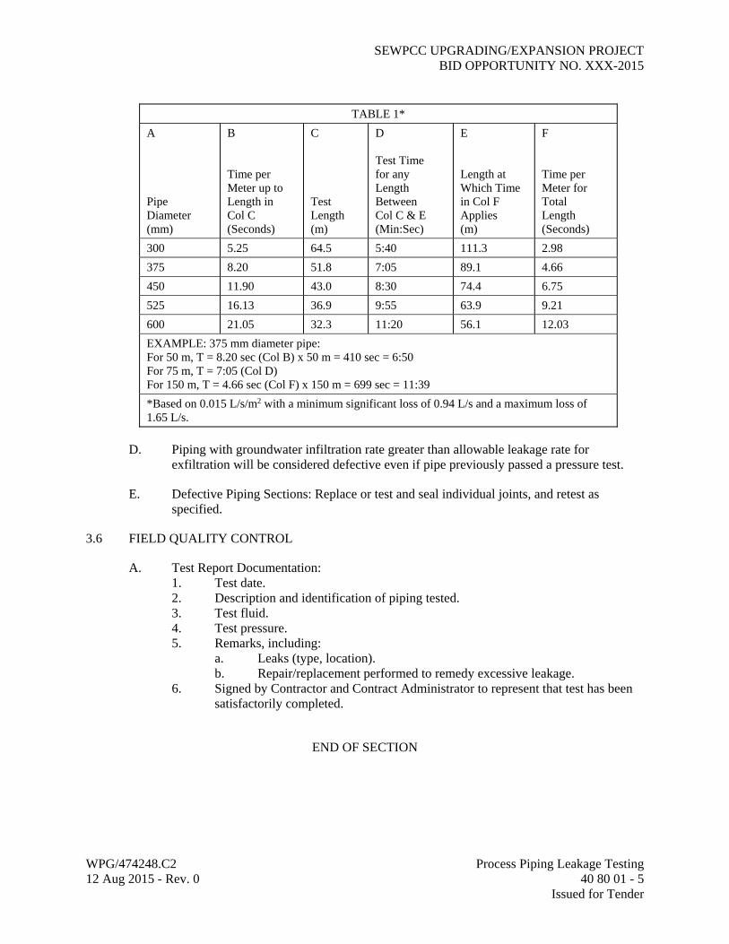
SEWPCC UPGRADING/EXPANSION PROJECT BID OPPORTUNITY NO. XXX-2015
WPG/474248.C2 Process Piping Leakage Testing 12 Aug 2015 - Rev. 0 40 80 01 - 5 Issued for Tender
TABLE 1*
A Pipe Diameter (mm)
B Time per Meter up to Length in Col C (Seconds)
C Test Length (m)
D Test Time for any Length Between Col C & E (Min:Sec)
E Length at Which Time in Col F Applies (m)
F Time per Meter for Total Length (Seconds)
300 5.25 64.5 5:40 111.3 2.98
375 8.20 51.8 7:05 89.1 4.66
450 11.90 43.0 8:30 74.4 6.75
525 16.13 36.9 9:55 63.9 9.21
600 21.05 32.3 11:20 56.1 12.03
EXAMPLE: 375 mm diameter pipe: For 50 m, T = 8.20 sec (Col B) x 50 m = 410 sec = 6:50 For 75 m, T = 7:05 (Col D) For 150 m, T = 4.66 sec (Col F) x 150 m = 699 sec = 11:39
*Based on 0.015 L/s/m2 with a minimum significant loss of 0.94 L/s and a maximum loss of 1.65 L/s.
D. Piping with groundwater infiltration rate greater than allowable leakage rate for exfiltration will be considered defective even if pipe previously passed a pressure test.
E. Defective Piping Sections: Replace or test and seal individual joints, and retest as specified.
3.6 FIELD QUALITY CONTROL
A. Test Report Documentation: 1. Test date. 2. Description and identification of piping tested. 3. Test fluid. 4. Test pressure. 5. Remarks, including:
a. Leaks (type, location). b. Repair/replacement performed to remedy excessive leakage.
6. Signed by Contractor and Contract Administrator to represent that test has been satisfactorily completed.
END OF SECTION