shaping reverberating sound fields with an actively...
TRANSCRIPT
Shaping reverberating sound fields with an activelytunable metasurfaceGuancong Maa,b,c,1,2, Xiying Fanb,1,3, Ping Shenga,b,2, and Mathias Finka,d,2
aInstitute for Advanced Study, Hong Kong University of Science and Technology, Clear Water Bay, Kowloon, Hong Kong; bDepartment of Physics, HongKong University of Science and Technology, Clear Water Bay, Kowloon, Hong Kong; cDepartment of Physics, Hong Kong Baptist University, Kowloon Tong,Hong Kong; and dInstitut Langevin, CNRS, École supérieure de physique et de chimie industrielles de la Ville de Paris, Université Paris Sciences & Lettres,75005 Paris, France
Edited by John B. Pendry, Imperial College London, London, United Kingdom, and approved May 15, 2018 (received for review January 22, 2018)
A reverberating environment is a common complex medium forairborne sound, with familiar examples such as music halls andlecture theaters. The complexity of reverberating sound fields hashindered their meaningful control. Here, by combining acousticmetasurface and adaptive wavefield shaping, we demonstrate theversatile control of reverberating sound fields in a room. This isachieved through the design and the realization of a binary phase-modulating spatial sound modulator that is based on an activelyreconfigurable acoustic metasurface. We demonstrate usefulfunctionalities including the creation of quiet zones and hotspotsin a typical reverberating environment.
acoustics | reverberation | metasurface | wavefront shaping
Wave control is a challenging task in complex media, whereinwaves are scrambled by multiple scatterings (1). Over the
last decade, optical adaptive wavefront shaping has become animpressive tool to control light propagation through highly scat-tering systems (2, 3). These advances have largely been enabled bythe availability of highly tunable digital arrays, known as spatiallight modulators. They allow us to synthesize a wavefront matchedto a specific diffusive medium to achieve functionalities such asfocusing through turbid media (4–6), noninvasive imaging (7–10),holography (11), etc. This strategy was also developed recently inmicrowaves for wireless communications (12–14). As an importantclass of complex media, reverberating environments are com-monplace for airborne sound. Most indoor environments are re-verberating acoustic cavities. A sound from any source is multiple-scattered by boundaries (walls, ceiling, and floor) and objects(furniture, warm bodies, etc.), forming a 3D complex wavefield(15) that is similar to laser speckles. The control of sound in suchrooms is therefore an extremely challenging yet useful topic. Here,we propose an approach based on wavefront shaping. We dem-onstrate the active shaping of any reverberating sound field byintroducing a spatial sound modulator (SSM) that is a reconfig-urable acoustic metasurface acting as an array of binary phasemodulators. The SSM, which has the lateral dimension of severalwavelengths and only covers a small fraction of the total surfacearea of the room, can drastically alter the sound field, while thesource and the room remain unchanged. Experiments show thesuccessful creation of “quiet zones” as well as an “acoustic hotspot”in a reverberating room. With this method, the reverberation of aroom is no longer a constraint but becomes a tunable property.We conducted the investigation in our laboratory, which is ap-
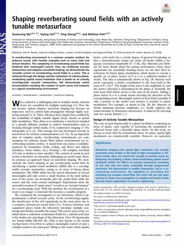
proximately a cuboid acoustic cavity. At the reverberating regime,the interference of the rich eigenmodes in the room gives rise toa complex, disordered sound field (15). Various furniture andequipment pieces inside the laboratory introduce multiple scat-terings that further scramble the sound. This can be seen in Fig. 1A,which shows a collection of simulated fields for a cuboid cavity thatis the similar size and shape of the laboratory. Over 30 eigenmodesare found within 600–601 Hz. [This is also known as the modaloverlap factor (16).] How to achieve meaningful control of such acomplex sound is our main goal. Owing to the room’s finite quality
factor, each mode has a certain degree of spectral broadening, sothat a monochromatic sound can excite all modes within a fre-quency correlation bandwidth of ∼5 Hz. (See Materials and Meth-ods for more details about the testing environment.) Since theseeigenmodes are essentially standing waves, we can alter their in-terference by binary phase modulation, which means to encode aspecific set of phase factors of 0 or π to a sufficient number ofmodes. The idea is schematically shown in Fig. 1B, wherein eacharrow represents a mode’s contribution to the local field in theform of P=P0eiϕ. The length of the arrow is the amplitude P0, andthe arrow’s direction is determined by the phase ϕ. Naturally, thetotal local field (black arrow) is the sum of all arrows. Adding aphase factor of π to a mode means inverting the direction of thecorresponding arrow. Meaningful control of local field is possible ifonly a portion of the modes (red arrows) is sensitive to phasemodulation. For example, as shown in Fig. 1B, the objective toobtain minimum pressure amplitude, i.e., locally suppress thesound intensity by destructive interference, is achieved by invertingonly two arrows labeled 1, 3.
Design of Actively Tunable MetasurfaceThe core of such functionality is a phase modulator comprising anarray of pixels, each capable of bestowing the transmitted orreflected waves with a desirable phase factor. In this work, wechoose to work with the transmitted waves. In optics, spatial lightmodulators are commercially available. However, no equivalent
Significance
Wavefront shaping with spatial light modulators has recentlymotivated many studies in the field of light manipulation in dif-fusive media. Here, we extend this concept to acoustic waves bydesigning and building a binary phase-modulating spatial soundmodulator (SSM). The SSM is an acoustic metasurface consistingof unit cells with two states, switchable through programmedelectronics. We demonstrate in audible frequencies, and in a re-verberating environment, the capability of controlling andreshaping any complex sound field. Our work will not only openavenues to studywave propagation in complex and chaotic mediabut also inspire applications in acoustic engineering.
Author contributions: G.M. and M.F. designed research; G.M. and X.F. performed re-search; G.M., X.F., P.S., and M.F. analyzed data; and G.M., P.S., and M.F. wrote the paper.
The authors declare no conflict of interest.
This article is a PNAS Direct Submission.
This open access article is distributed under Creative Commons Attribution-NonCommercial-NoDerivatives License 4.0 (CC BY-NC-ND).1G.M. and X.F. contributed equally to this work.2To whom correspondence may be addressed. Email: [email protected], [email protected], or [email protected].
3Present address: School of Physics and Technology, Wuhan University, Wuhan 430072,China.
This article contains supporting information online at www.pnas.org/lookup/suppl/doi:10.1073/pnas.1801175115/-/DCSupplemental.
www.pnas.org/cgi/doi/10.1073/pnas.1801175115 PNAS Latest Articles | 1 of 6
ENGINEE
RING
device exists for airborne sound. Moreover, the inherently longwavelength of airborne sound presents an additional challenge forphase manipulation within a small device. The recent advent ofacoustic planar metamaterials/metasurfaces (17–19) offers a po-tential solution for such a task. Since the existing acoustic meta-surfaces are not actively reconfigurable, we have designed andrealized an actively reconfigurable acoustic metasurface that canplay the crucial role of a deep-subwavelength, phase-modulatingbinary spatial sound modulator (SSM).
The SSM is based on membrane-type resonators (MRs) thathave been studied in previous works (20–24). The MR reso-nates under the excitation of subkilohertz airborne sound; eachof its resonances can introduce (in the absence of dissipation) aphase change of π in the transmitted wave. If we can activelyshift a resonance between two frequencies, a phase factor ofeither 0 or π can be attained for transmitted sound in the in-termediate frequency range, thereby leading to binary phasemodulation (12, 25).
oF uru u in ts as one pixel
A
B
Relay modules
To micro-controllers
Re(P) Re(P)
Im(P)Im(P)
1 12
2
33
)noitaziminim(dezimitpOlanigirO
600.01 Hz
600.03 Hz
600.05 Hz
600.09 Hz
600.12 Hz
600.16 Hz
600.19 Hz
1 0 -1
Pressure field (a. u.)
C SSM in the lab.
Fig. 1. A collection of simulated eigenmodes of a cavity of similar size and shape with our laboratory is shown in A. These modes constitute the degree offreedom for controlling reverberating sound via SSM. The control concept is shown in B. Each arrow is a complex number that represents a mode’s contribution tothe local field. Blue arrows represent modes unaffected by SSM’s modulation. Red arrows are modes sensitive to the modulation. In binary phase modulation, toobtain the smallest total field (shortest black arrow), two arrows labeled 1, 3 are inverted, which means picking up a phase factor of π. Photos in C show the SSM,which consists totally 360 units of binary active MRs. Four units are grouped together as one pixel, each being electrically controlled by programmable electronics.
+
Membrane(transparent in experiment)
Magnet
Electromagnet (fixed)+
OFF-state ON-state
Loop
Magnet free; membrane has one fixed boundary at the edge (red circle).
Magnet snapped to electromagnet; membranehas two fixed boundaries (blue circles).
A B C
OFF-state ON-state
OFF-state
ON-state
OFF-State
ON-State
ON-State
4
6
0.1
2
4
6
1
neiffeocnois si
msnar Tt c
800600400Frequency (Hz)
-50
0
50 hP
)ged
(e s
a
OFF-State
1.0
0.8
0.6
0.4
0.2
ocnoitcel fe
Rtneiciffe
-50
0
50
d(es
ahP
)ge
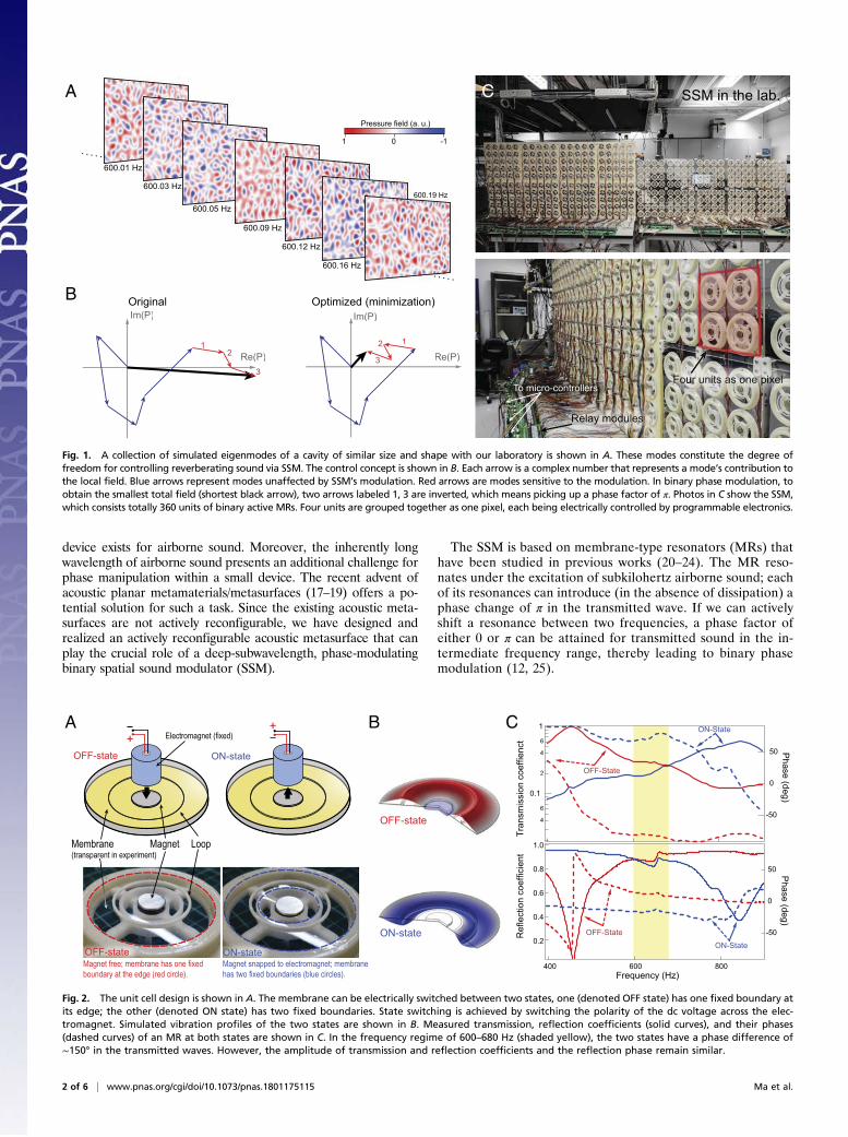
Fig. 2. The unit cell design is shown in A. The membrane can be electrically switched between two states, one (denoted OFF state) has one fixed boundary atits edge; the other (denoted ON state) has two fixed boundaries. State switching is achieved by switching the polarity of the dc voltage across the elec-tromagnet. Simulated vibration profiles of the two states are shown in B. Measured transmission, reflection coefficients (solid curves), and their phases(dashed curves) of an MR at both states are shown in C. In the frequency regime of 600–680 Hz (shaded yellow), the two states have a phase difference of∼150° in the transmitted waves. However, the amplitude of transmission and reflection coefficients and the reflection phase remain similar.
2 of 6 | www.pnas.org/cgi/doi/10.1073/pnas.1801175115 Ma et al.
The unit cell designed to achieve the above function is shownin Fig. 2A. A circular elastic membrane is stretched and fixed atthe edge. A small magnet disk and a plastic loop are attached tothe membrane as loaded mass to tune its eigenmodes. A resonanceis identified as a transmission peak at 450 Hz (Fig. 2C, red). Tomake the unit cell actively tunable, we place a small electromagnetdirectly above the magnet disk, separated by a small gap, asdepicted in Fig. 2A. By applying a dc voltage, the electromagnetcan firmly snap the magnet disk to stop the vibration of the innerpart of the membrane. This imposes an additional fixed boundarywithin the membrane, effectively turning the circular membraneinto an annular one, as shown in Fig. 2A. We denote this as theunit’s “ON state.” Inverting the dc voltage changes the polarity ofthe electromagnet and releases the MR to its original state, whichwe denote as “OFF state.” This change of the MR significantlyimpacts its eigenmodes, as shown in the vibration profiles in Fig.2B. Notably, the resonant peak at the OFF state near 450 Hz isshifted to 850 Hz at the ON state (Fig. 2C). In the frequency re-gime of 600–680 Hz, we observe that the MR at its two switchablestates has a phase difference of ∼150° in the transmitted waves, butthe amplitude of transmission and reflection coefficients, as well asphases of the reflected waves, remain at a similar level. Thisproperty is suitable for a binary phase-modulating SSM.
We have fabricated a metasurface comprising 360 identicalunits of MRs in a 2D array (Fig. 1C). The array has a total areaof 2.3 m2, which is less than 1% of the laboratory’s total boundaryarea. The lateral dimension of the MRs is subwavelength and istherefore not desirable for controlling the far field. We mitigatethis problem by grouping four units into a 2 × 2 array to form onefunctional pixel. With each MR unit controlled by programmableelectronics, the metasurface becomes an SSM that has a totalof 90 pixels.
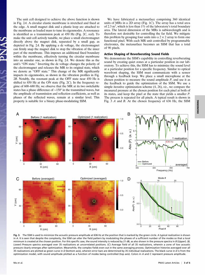
Active Shaping of Reverberating Sound FieldsWe demonstrate the SSM’s capability in controlling reverberatingsound by creating quiet zones at a particular position in our lab-oratory. To achieve this, the SSM has to minimize the sound levelat a particular position for a specific frequency. Similar to opticalwavefront shaping, the SSM must communicate with a sensorthrough a feedback loop. We place a small microphone at thechosen position to measure the sound amplitude P, and use it asthe feedback to guide the optimization of the SSM. We use asimple iterative optimization scheme (4, 26), viz., we compare themeasured pressure at the chosen position for each pixel at both ofits states, and keep the pixel at the state that yields a smaller P.The process is repeated for all pixels. A typical result is shown inFig. 3 A and B. At the chosen frequency of 636 Hz, the SSM
4
6
0.1
2
4
6
1
60
30
0
60300X (cm)
60
30
0
)mc(
Y
60300X (cm)
X (cm)X (cm)
60
30
0
)mc(
Y
60300
60
30
0
60300
1.0
0.5
0.0
1.0
0.5
0.0
A B
DC
Before (1 realization)
Before (averaged)
Optimized (1 realization)
Optimized (averaged)
).u.a()
P(sb
A
1 realization
averaged
636 Hz
Before Optimized
2
4
6
8
1
700650600550Frequency (Hz)
1.0
0.5
0.0
.a()
P(sbA
).u
806040200Pixel #
20100Mode #
Fig. 3. The SSM is used to minimize the acoustic pressure amplitude at 636 Hz at the position that is marked by the green circle. A typical realization is shownin A. It is seen that despite the complexity, the SSM can alter the field pattern by modulating the phases of a sufficient number of the modes so that a localminimum is created at the chosen position. For this specific case, the sound intensity is reduced by 21 dB, as also shown in the pressure spectra in B (Upper). (B,Lower) Pressure spectra averaged over 35 realizations at uncorrelated positions. (C) Average field of all 35 realizations, wherein a zone of low acousticpressure clearly emerges after optimization. Meanwhile, the complex fields even out in the same averaging process. Optimization histories averaged over all35 realizations are plotted as green curve in D (bottom axis), wherein error bars are determined by 35 individual realizations. The black curve in D is from theoptimization model, with sound amplitude plotted as a function of modes being controlled (top axis). Colors in A and C represent pressure amplitude.
Ma et al. PNAS Latest Articles | 3 of 6
ENGINEE
RING
reduces the sound intensity by 21 dB (Fig. 3B). We further obtainspatial maps of the sound fields before and after optimization, asshown in Fig. 3A. First, we see that field patterns in both cases aredisordered, which conforms with the complex characteristics ofreverberating sound. Despite such complexity, we clearly see thata region of small sound pressure emerges at the optimizationposition, which is marked by the green circle.We have further performed 35 independent minimization ex-
periments for 636 Hz at uncorrelated positions in the laboratory.In Fig. 3C we show the averaged field patterns of all 35 experi-ments. It is seen that the preoptimized field has relatively uniformdistribution after averaging, which is yet another evidence of thedisordered characteristic of reverberating sound. The optimizedfield, however, clearly shows a diffraction-limited zone of smallersound pressure at the optimized position. Also, from the averagedfrequency response at the optimized positions (Fig. 3B), we cansee that P is significantly reduced near 636 Hz. In addition, theminimization histories averaged over all 35 experiments are shownin Fig. 3D. We can clearly see that as each pixel’s state is se-quentially determined, P indeed steadily decreases throughout theprocess. This is further evidence of the effectiveness of the SSM.The minimization process can be reproduced with a simple nu-merical model (details are presented in Materials and Methods).The result from the model is also shown in Fig. 3D. Excellentagreement is seen. On average, the minimization can reduce the
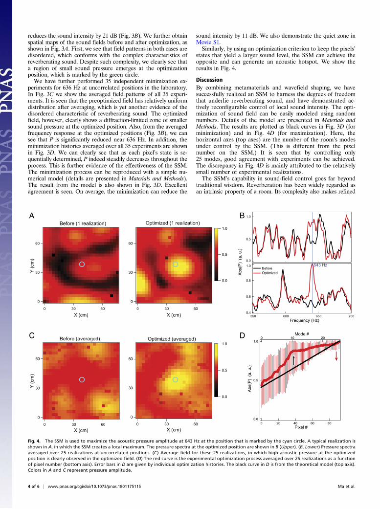
sound intensity by 11 dB. We also demonstrate the quiet zone inMovie S1.Similarly, by using an optimization criterion to keep the pixels’
states that yield a larger sound level, the SSM can achieve theopposite and can generate an acoustic hotspot. We show theresults in Fig. 4.
DiscussionBy combining metamaterials and wavefield shaping, we havesuccessfully realized an SSM to harness the degrees of freedomthat underlie reverberating sound, and have demonstrated ac-tively reconfigurable control of local sound intensity. The opti-mization of sound field can be easily modeled using randomnumbers. Details of the model are presented in Materials andMethods. The results are plotted as black curves in Fig. 3D (forminimization) and in Fig. 4D (for maximization). Here, thehorizontal axes (top axes) are the number of the room’s modesunder control by the SSM. (This is different from the pixelnumber on the SSM.) It is seen that by controlling only25 modes, good agreement with experiments can be achieved.The discrepancy in Fig. 4D is mainly attributed to the relativelysmall number of experimental realizations.The SSM’s capability in sound-field control goes far beyond
traditional wisdom. Reverberation has been widely regarded asan intrinsic property of a room. Its complexity also makes refined
0
30
60
)mc(
Y
0 30 60
0
30
60
0 30 60
1.0
0.5
0.0
1.0
0.5
0.0
A B
DC
Before Optimized
60
30
0
)mc(
Y
60300X (cm)
X (cm)
60
30
0
60300X (cm)
X (cm)
Before (1 realization) Optimized (1 realization)
Before (averaged) Optimized (averaged)
1.0
0.8
0.6
0.4
A).u.a(
)P(sb
700650600550Frequency (Hz)
1.0
0.5
0.0643 Hz
1.0
0.5
0.0
).u.a()
P(sbA
806040200Pixel #
20100Mode #
Fig. 4. The SSM is used to maximize the acoustic pressure amplitude at 643 Hz at the position that is marked by the cyan circle. A typical realization isshown in A, in which the SSM creates a local maximum. The pressure spectra at the optimized position are shown in B (Upper). (B, Lower) Pressure spectraaveraged over 25 realizations at uncorrelated positions. (C) Average field for these 25 realizations, in which high acoustic pressure at the optimizedposition is clearly observed in the optimized field. (D) The red curve is the experimental optimization process averaged over 25 realizations as a functionof pixel number (bottom axis). Error bars in D are given by individual optimization histories. The black curve in D is from the theoretical model (top axis).Colors in A and C represent pressure amplitude.
4 of 6 | www.pnas.org/cgi/doi/10.1073/pnas.1801175115 Ma et al.
control extremely difficult. Its alteration usually requires an over-haul of the interior design. The creation of quiet zones anywhere ina room has the application value as a versatile noise abatementsolution. Acoustic hotspots will be useful to improve audio quality,which may benefit music experience, oral communications, etc. Inaddition to these local modifications, the way SSM redistributesexisting acoustic energy may even affect the global acoustic prop-erties of the environment. For example, maximizing sound intensityat a position with localized high absorption can lead to the re-duction of average sound level in the room, which is similar tocoherent enhanced absorption (27).We further point out that the way the SSM rearranges the
distribution of the acoustic energy is fundamentally differentfrom existing methods of active sound control, which demandadditional source components that emit sound waves with theproper phase to cancel the sound field at the designated position(28), or to improve absorption performance (28–30). In com-parison, the SSM consumes almost no energy unless the pixelsare switching. The instability issues in active sound control, suchas those caused by feedback time lag or phase errors, are non-existent in our approach.The sound-field control demonstrated in this paper is nar-
rowband. However, such characteristic is mainly due to the op-timization scheme, wherein the sound amplitude of a singlefrequency is used for feedback. Broadband control is also pos-sible since the SSM can control the phases for modes in a muchbroader frequency regime (Fig. 2C). We show some results ofbroadband control in SI Appendix, Fig. S1. It is possible to fur-ther improve the performance by unit cell design. Since the MRsare highly tunable in their resonant frequencies, the SSM’sbandwidth can be straightforwardly increased by combining MRswith mismatching resonant frequencies into supercells to act aspixel units. Also, smarter, more efficient optimization schemescan also play an important role in broadband control.On the other hand, an SSM that modulates the amplitude or
the phase of reflected waves may be a worthy goal for futuredevelopment, since it can be integrated as a part of the boundarywall of the room.
Materials and MethodsThe Design of the SSM. The SSM consists of 360 units of MRs grouped into90 pixels. For each MR unit, a polyurethane membrane (27 mm in radius and0.1 mm in thickness) is uniformly stretched by 10% and then glued to a plasticframe. A neodymiummagnet disk with a radius of 6mm and amass of 0.9 g isattached to the center of the membrane. A plastic loop (inner/outer radius of16/17 mm, 0.15 g) is also attached to the membrane. The disk and the looptune one of MR’s eigenmodes to 450 Hz. A miniature electromagnet issuspended at 2.5 mm from the membrane by a rigid plastic support. Em-bodied in the plastic support is a ring-shaped plateau. A small gap of 1 mmseparates the membrane from this plateau. The magnet disk on the mem-brane snaps to the electromagnet when a suction magnetic force is estab-lished by applying dc voltage. The change in the magnet’s position deformsthe membrane and brings it into tight contact with the plateau. The con-straint of the magnetic force essentially enforces a second fixed boundarythat is the edge of the ring-shaped plateau. The membrane inside of theplateau becomes stationary at the frequency range of interest. The MR inthis state, which we denote ON state, essentially has an annular shape.Inverting the dc voltage across the electromagnet inverts the direction ofmagnetic force so that the magnet and the membrane are pushed away torestore their free position. The membrane therefore retains circular shape,and resumes its original state that is denoted OFF state.
To switch each unit cell through dc voltage of different polarity (±15 V), allelectromagnets are individually connected to an electrical relay. The relaymodules are further controlled by eight units of Arduino Mega 2560 micro-controllers, which are programmed by a PC.
The Testing Environment. The experiments are performed in our laboratory,which is roughly a cuboid room with a dimension of 9.0(L) × 6.0(W) × 4.5(H)m. It can be considered reverberating above the Schroeder frequency
fs =2,000ffiffiffiffiffiffiffiffiffiffiffiffiffiffiffiT60V−1
p≈ 108Hz, wherein V is the room’s volume and T60 is the
room’s reverberation time for a 60-dB decay, which is measured to be about0.7 s. The SSM is placed upright in the laboratory to take advantage of the phasechange in the transmitted waves. The source is an omnidirectional loudspeaker.
The laboratory, which is an enclosed acoustic cavity, is characterized byits eigenmodes and the quality factor. The finite quality factor determinesthat each resonance has a certain degree of spectral broadening. Thismeans a monochromatic excitation at frequency f can excite a wealth ofresonances that lie within a frequency correlation bandwidth fcor [alsocalled “correlation frequency” in some literature (2)]. For a cuboidal cavitythat is the basic shape of the room, the number of eigenmodes is esti-mated to be (15)
n=�4πVc3
f2 +πS2c2
f +L8c
�fcor ,
where V is the volume of the cavity, S is the total area of all boundaries, L isthe total length of all edges, and c is the speed of sound. n is also knownas the modal overlap factor that is commonly used for noise control(16). fcor is related to the quality factor and therefore the exponential
decay time τ through fcor =Q−1f = ðπτÞ−1. We measured τ with the inter-rupted signal method (with a sinusoidal source at 636 Hz) at multiplelocations in the laboratory and obtained τ≈ 0.06 s, which gives fcor ≈5Hz.Consequently, we have n≈165 at f =636Hz. These modes, essentiallystanding waves inside the cavity, become the spatial degrees of free-dom that can be accessed by the SSM to reshape the sound field. Ir-regular geometric features and scattering objects further scramble thefield in the laboratory.
Experimental Configurations. During testing, no preference was given to therelative positions among the source, the SSM, and the optimization point.Typical layouts are schematically illustrated in SI Appendix, Fig. S2. In-dependent sets of experiments were carried out at uncorrelated positions,which are more than half a wavelength apart. All possible configurations areincluded: the source and the optimization point can be on a different side orthe same side of the SSM; they can be close [but larger than the re-verberation radius (31), which is about 1 m] or far apart; there may or maynot be a direct line of sight among them.
Modeling the Optimization. The optimization of sound field can be numeri-cally modeled. Here, we observe that total field at any position at a givenfrequency is
Pt =Xni=1
Pieiϕi .
Pi is the local amplitude of the ith cavity mode at the chosen position, ϕi isthe corresponding phase factor. n is the modal overlap factor, which is165 for our experiments. According to the randomness characteristics ofthe reverberating field, we can use computer-generated pseudorandomnumbers to simulate the optimization process. The simulation strategy forminimization goes as follows. First, we construct ui = Pieiϕi using randomnumbers, wherein Pi is positive random numbers between ð0, 1Þ, ϕi israndom numbers lying between ð–π, πÞ. There are in total 165 numbers forui, corresponding to the n= 165 in our experiments. Second, we randomlychoose σ ≤n numbers from ui, and alter the phase ϕi to ϕi +0.8π for each ui
(corresponds to the ∼150° phase factor bestowed by a pixel in our ex-periments). Then, choose the phase that yields a smaller Pt. Physically, σ isthe number of modes controlled by the SSM, so there must be σ ≤n. Sincethe exact number of modes under control is unknown in our experiment,we treat σ as the only tuning parameter in our model. (It should be notedthat although the SSM has 90 pixels, exactly how many modes it cancontrol is unknown.) Then, we record Pt for every step and repeat theprocess multiple times. The results from this model are shown in Figs. 3Dand 4D. The numerical results are then averaged over 1,000 realizations.The number of modes under control is σ = 25. Good agreement with ex-periment is achieved. Some discrepancies are attributed to the relativelysmall number of experimental realizations (especially for the maximiza-tion results which have fewer realizations).
Performance Analysis. Several factors limit the performance of the SSM. Fromthe aboveanalysis of the experimental environment,with only 90pixels, our SSMis insufficient to fully control the modes in the room (13). In addition, nonidealtransmission coefficients of ∼0.3 (Fig. 2C) are observed for the MR in the op-erational frequency regime, which directly diminishes the overall performance,since the SSM only imprints phase factors to the transmitted waves. (This is why
Ma et al. PNAS Latest Articles | 5 of 6
ENGINEE
RING

the red arrows in Fig. 1B are shorter, which means smaller amplitudes.)Moreover, the inevitable dissipation associated with the MR slightly diminishesthe phase change to ∼150°, instead of 180° that is the ideal value. This explainsthat in the averaged results (Fig. 3 B and C), the nonzero amplitude is seen atthe minimization position, indicating imperfect destructive interference. Toovercome these factors will be a goal of future studies.
With a continuous monochromatic excitation, our iterative method takesless than 9 min to complete the optimization for all pixels. Many viable pathscan improve this performance. Smarter optimizationmethods such as geneticalgorithm, machine-learning, etc., are good candidates to reduce the runtime.
Prior knowledge of the environment and the sound field can also be integratedinto the algorithm for better performance.
ACKNOWLEDGMENTS. We thank Yue Xiao and Shuyu Chen for samplefabrication, and Walter Ching Lee for electronics and circuit design. G.M.thanks Philipp del Hougne, Matthieu Dupré, and Geoffroy Lerosey forhelpful discussions. G.M., X.F., and P.S. acknowledge the support of Inno-vation and Technology Commission of Hong Kong Government throughProject ITF/203/15. G.M. and P.S. also acknowledge the support of theHong Kong Research Grants Council (Grant AoE/P-02/12).
1. Sheng P (2006) Introduction to Wave Scattering, Localization and MesoscopicPhenomena (Springer, Berlin).
2. Mosk AP, Lagendijk A, Lerosey G, Fink M (2012) Controlling waves in space and timefor imaging and focusing in complex media. Nat Photonics 6:283–292.
3. Rotter S, Gigan S (2017) Light fields in complex media: Mesoscopic scattering meetswave control. Rev Mod Phys 89:015005.
4. Vellekoop IM, Mosk AP (2007) Focusing coherent light through opaque stronglyscattering media. Opt Lett 32:2309–2311.
5. Vellekoop I, Lagendijk A, Mosk A (2010) Exploiting disorder for perfect focusing. NatPhotonics 4:320–322.
6. Choi Y, et al. (2011) Overcoming the diffraction limit using multiple light scattering ina highly disordered medium. Phys Rev Lett 107:023902.
7. Popoff S, Lerosey G, Fink M, Boccara AC, Gigan S (2010) Image transmission throughan opaque material. Nat Commun 1:81.
8. Bertolotti J, et al. (2012) Non-invasive imaging through opaque scattering layers.Nature 491:232–234.
9. Katz O, Heidmann P, Fink M, Gigan S (2014) Non-invasive single-shot imaging throughscattering layers and around corners via speckle correlations. Nat Photonics 8:784–790.
10. Katz O, Small E, Silberberg Y (2012) Looking around corners and through thin turbidlayers in real time with scattered incoherent light. Nat Photonics 6:549–553.
11. Yu H, Lee K, Park J, Park Y (2017) Ultra high-definition dynamic 3D holographicdisplay by active control of volume speckle fields. Nat Photonics 11:186–192.
12. Kaina N, Dupré M, Lerosey G, Fink M (2014) Shaping complex microwave fields inreverberating media with binary tunable metasurfaces. Sci Rep 4:6693.
13. Dupré M, del Hougne P, Fink M, Lemoult F, Lerosey G (2015) Wave-field shaping incavities: Waves trapped in a box with controllable boundaries. Phys Rev Lett 115:017701.
14. Del Hougne P, Lemoult F, Fink M, Lerosey G (2016) Spatiotemporal wave frontshaping in a microwave cavity. Phys Rev Lett 117:134302.
15. Kuttruff H (2009) Room Acoustics (Taylor & Francis, New York).16. Lyon RH, Dejong RG (2014) Theory and Application of Statistical Energy Analysis
(Butterworth-Heinemann, Boston).17. Cummer SA, Christensen J, Alù A (2016) Controlling sound with acoustic meta-
materials. Nat Rev Mater 1:16001.18. Ma G, Sheng P (2016) Acoustic metamaterials: From local resonances to broad hori-
zons. Sci Adv 2:e1501595.19. Xu Y, Fu Y, Chen H (2016) Planar gradient metamaterials. Nat Rev Mater 1:16067.20. Yang Z, Mei J, Yang M, Chan NH, Sheng P (2008) Membrane-type acoustic meta-
material with negative dynamic mass. Phys Rev Lett 101:204301.21. Xiao S, Ma G, Li Y, Yang Z, Sheng P (2015) Active control of membrane-type acoustic
metamaterial by electric field. Appl Phys Lett 106:091904.22. Ma G, Yang M, Xiao S, Yang Z, Sheng P (2014) Acoustic metasurface with hybrid
resonances. Nat Mater 13:873–878.23. Ma G, Yang M, Yang Z, Sheng P (2013) Low-frequency narrow-band acoustic filter
with large orifice. Appl Phys Lett 103:011903.24. Yang M, Ma G, Yang Z, Sheng P (2013) Coupled membranes with doubly negative
mass density and bulk modulus. Phys Rev Lett 110:134301.25. Akbulut D, Huisman TJ, van Putten EG, Vos WL, Mosk AP (2011) Focusing light
through random photonic media by binary amplitude modulation. Opt Express 19:4017–4029.
26. Vellekoop I, Mosk A (2008) Phase control algorithms for focusing light through turbidmedia. Opt Commun 281:3071–3080.
27. Chong YD, Stone AD (2011) Hidden black: Coherent enhancement of absorption instrongly scattering media. Phys Rev Lett 107:163901.
28. Nelson PA, Elliott SJ (1991) Active Control of Sound (Academic, London).29. Olson HF, May EG (1953) Electronic sound absorber. J Acoust Soc Am 25:1130–1136.30. Cox TJ, D’Antonio P (2009) Acoustic Absorbers and Diffusers: Theory, Design and
Application (CRC Press, Boca Raton, FL).31. Miji�c M, Masovic D (2010) Reverberation radius in real rooms. Telfor J 2:86–91.
6 of 6 | www.pnas.org/cgi/doi/10.1073/pnas.1801175115 Ma et al.