shenzhen toby technology co., ltd. · the testing report were performed by the shenzhen toby...
TRANSCRIPT
Shenzhen Toby Technology Co., Ltd.
Report No.: TB-IC156753
Page: 1 of 21
TB-RF-074-1.0
1A/F., Bldg.6, Yusheng Industrial Zone, The National Road No.107 Xixiang Section 467, Xixiang, Bao’an, Shenzhen, China
Tel: +86 75526509301 Fax: +86 75526509195
ICES-003 Test Report
Certificate No. : TB171017114
Applicant : BIOMEDIS TECHNOLOGIES CO., LIMITED
Equipment Under Test (EUT)
EUT Name : TRINITY
Model No. : T-1
Serial Model No. : N/A
Brand Name : N/A
Receipt Date : 2017-10-23
Test Date : 2017-10-23 to 2017-10-27
Issue Date : 2017-10-27
Standards : ICES-003 Issue 6: 2016 Class B
Test Methods : ANSI C63.4: 2014
Conclusions : Compliance
In the configuration tested, the EUT complied with the standards specified above
Test/Witness Engineer :
ICES-003 Approved & Authorized :
This report details the results of the testing carried out on one sample. The results contained in this test report do not relate to other samples of the same product. The manufacturer should ensure that all products in series production are in conformity with the product sample detailed in the report.
Report No.: TB-IC156753
Page: 2 of 21
TB-RF-074-1.0
Contents
CONTENTS ............................................................................................................................................. 2
1. GENERAL INFORMATION ...................................................................................................... 4
1.1 Client Information ................................................................................................................. 4 1.2 General Description of EUT (Equipment Under Test) ................................................... 4 1.3 Description of Test Mode .................................................................................................... 4 1.4 Block Diagram Showing The Configuration of System Tested..................................... 5 1.5 Description of Support Units .............................................................................................. 5 1.6 Test standards ...................................................................................................................... 6 1.7 Test Facility ........................................................................................................................... 6 1.8 Measurement Uncertainty .................................................................................................. 6
2. TEST SUMMARY ....................................................................................................................... 7
3. TEST EQUIPMENT USED ....................................................................................................... 8
4. CONDUCTED EMISSION TEST ............................................................................................. 9
4.1 Test Standard and Limit ...................................................................................................... 9 4.2 Test Setup ............................................................................................................................. 9 4.3 Test Procedure ................................................................................................................... 10 4.4 Test Data ............................................................................................................................. 10
5. RADIATED EMISSION TEST ................................................................................................ 11
5.1 Test Standard and Limit .................................................................................................... 11 5.2 Test Setup ........................................................................................................................... 12 5.3 Test Procedure ................................................................................................................... 12 5.4 Test Data ............................................................................................................................. 12
6. PHOTOGRAPHS - CONSTRUCTIONAL DETAILS .......................................................... 13
7. PHOTOGRAPHS - TEST SETUP ......................................................................................... 17
ATTACHMENT B--RADIATED EMISSION TEST DATA ............................................................. 18
Report No.: TB-IC156753
Page: 3 of 21
TB-RF-074-1.0
Revision History
Report No. Version Description Issued Date
TB-IC156753 Rev.01 Initial issue of report 2017-10-27

Report No.: TB-IC156753
Page: 4 of 21
TB-RF-074-1.0
1. General Information
1.1 Client Information
Applicant : BIOMEDIS TECHNOLOGIES CO., LIMITED
Address : Unit E223, 3/F Wing Tat Comm, Bldg 97 Bonham Strand East, Sheung Wan, Hong Kong.
Manufacturer : BIOMEDIS TECHNOLOGIES CO., LIMITED
Address : Unit E223, 3/F Wing Tat Comm, Bldg 97 Bonham Strand East, Sheung Wan, Hong Kong.
1.2 General Description of EUT (Equipment Under Test)
EUT Name : TRINITY
Model(s) : T-1
Model Difference
: /
Power Supply : DC 5V
Remark: /
1.3 Description of Test Mode
To investigate the maximum EMI emission characteristics generates from EUT, the test system was pre-scanning tested base on the consideration of following EUT operation mode or test configuration mode which possible have effect on EMI emission level. Each of these EUT operation mode(s) or test configuration mode(s) mentioned follow was evaluated respectively.
For Conducted Test
Final Test Mode Description
Mode 1 N/A
For Radiated Test
Final Test Mode Description
Mode 1 Charging Mode
Mode 2 Normal Mode

Report No.: TB-IC156753
Page: 5 of 21
TB-RF-074-1.0
1.4 Block Diagram Showing The Configuration of System Tested
1.5 Description of Support Units
The EUT has been tested as an independent unit.
Monitor
Modem
PC
Printer
Keyboard Mouse
EUT
Mode 1
Mode 2
EUT

Report No.: TB-IC156753
Page: 6 of 21
TB-RF-074-1.0
1.6 Test standards
The objective is to determine compliance with ICES-003, Class B, and section 6.1, 6.2 rules. Maintenance of compliance is the responsibility of the manufacturer. Any modification of the product, which result in lowering the emission, should be checked to ensure compliance has been maintained.
1.7 Test Facility
The testing report were performed by the Shenzhen Toby Technology Co., Ltd., in their facilities located at 1A/F., Bldg.6, Yusheng Industrial Zone, The National Road No.107 Xixiang Section 467, Xixiang, Bao’an, Shenzhen, Guangdong, China. At the time of testing, the following bodies accredited the Laboratory: CNAS (L5813) The Laboratory has been accredited by CNAS to ISO/IEC 17025: 2005 General Requirements for the Competence of Testing and Calibration Laboratories for the competence in the field of testing. And the Registration No.: CNAS L5813. FCC List No.: (811562) The Laboratory is listed in the United States of American Federal Communications Commission (FCC), and the registration number is 811562. IC Registration No.: (11950A-1) The Laboratory has been registered by Certification and Engineering Bureau of Industry Canada for radio equipment testing. The site registration: Site# 11950A-1.
1.8 Measurement Uncertainty
The reported uncertainty of measurement y ± U,where expended uncertainty U is based on a standard uncertainty multiplied by a coverage factor of k=2,providing a level of confidence of approximately 95 %.
Test Parameters Expanded
Uncertainty (ULab)
Expanded
Uncertainty (UCispr)
Conducted Emission
Level Accuracy:
9kHz~150kHz
150kHz to 30MHz
±3.42 dB
±3.42 dB
±4.0 dB
±3.6 dB
Radiated Emission Level Accuracy:
30MHz to 1000 MHz±4.40 dB ±5.2 dB
Radiated Emission Level Accuracy:
Above 1000MHz ±4.20 dB N/A
Report No.: TB-IC156753
Page: 7 of 21
TB-RF-074-1.0
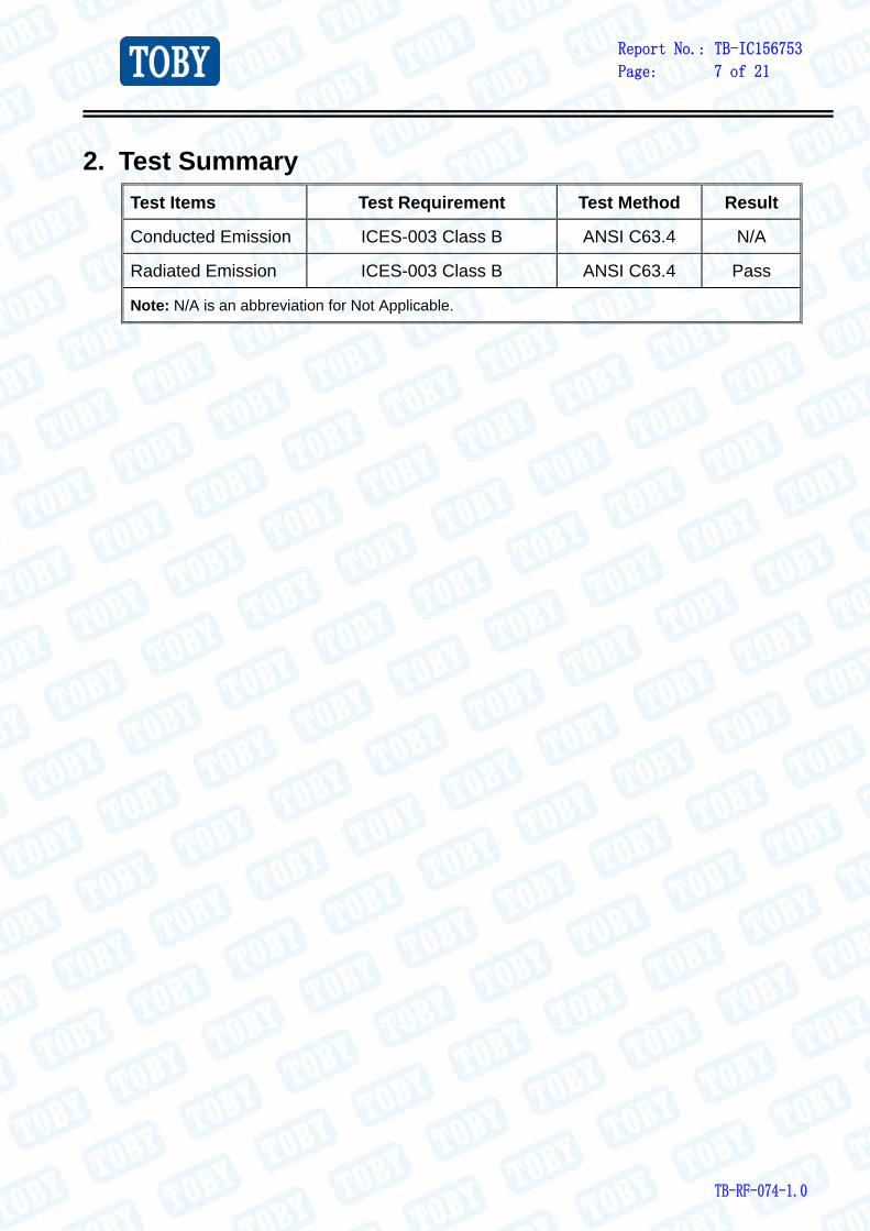
2. Test Summary
Test Items Test Requirement Test Method Result
Conducted Emission ICES-003 Class B ANSI C63.4 N/A
Radiated Emission ICES-003 Class B ANSI C63.4 Pass
Note: N/A is an abbreviation for Not Applicable.

Report No.: TB-IC156753
Page: 8 of 21
TB-RF-074-1.0
3. Test Equipment Used Radiation Emission Test
Equipment Manufacturer Model No. Serial No. Last Cal. Cal. Due Date
Spectrum
Analyzer Agilent E4407B MY45106456 Jul. 20, 2017 Jul. 19, 2018
EMI Test
Receiver Rohde & Schwarz ESCI 100010/007 Jul. 20, 2017 Jul. 19, 2018
Bilog Antenna ETS-LINDGREN 3142E 00117537 Mar.25, 2017 Mar. 24, 2018
Bilog Antenna ETS-LINDGREN 3142E 00117542 Mar.25, 2017 Mar. 24, 2018
Horn Antenna ETS-LINDGREN 3117 00143207 Mar.24, 2017 Mar. 23, 2018
Horn Antenna ETS-LINDGREN 3117 00143209 Mar.24, 2017 Mar. 23, 2018
Pre-amplifier HP 11909A 185903 Mar.24, 2017 Mar. 23, 2018
Pre-amplifier HP 8447B 3008A00849 Mar.25, 2017 Mar. 24, 2018
Cable HUBER+SUHNER 100 SUCOFLEX Mar.25, 2017 Mar. 24, 2018
Signal
Generator Rohde & Schwarz SML03 IKW682-054 Mar.25, 2017 Mar. 24, 2018
Positioning
Controller ETS-LINDGREN 2090 N/A N/A N/A
Report No.: TB-IC156753
Page: 9 of 21
TB-RF-074-1.0
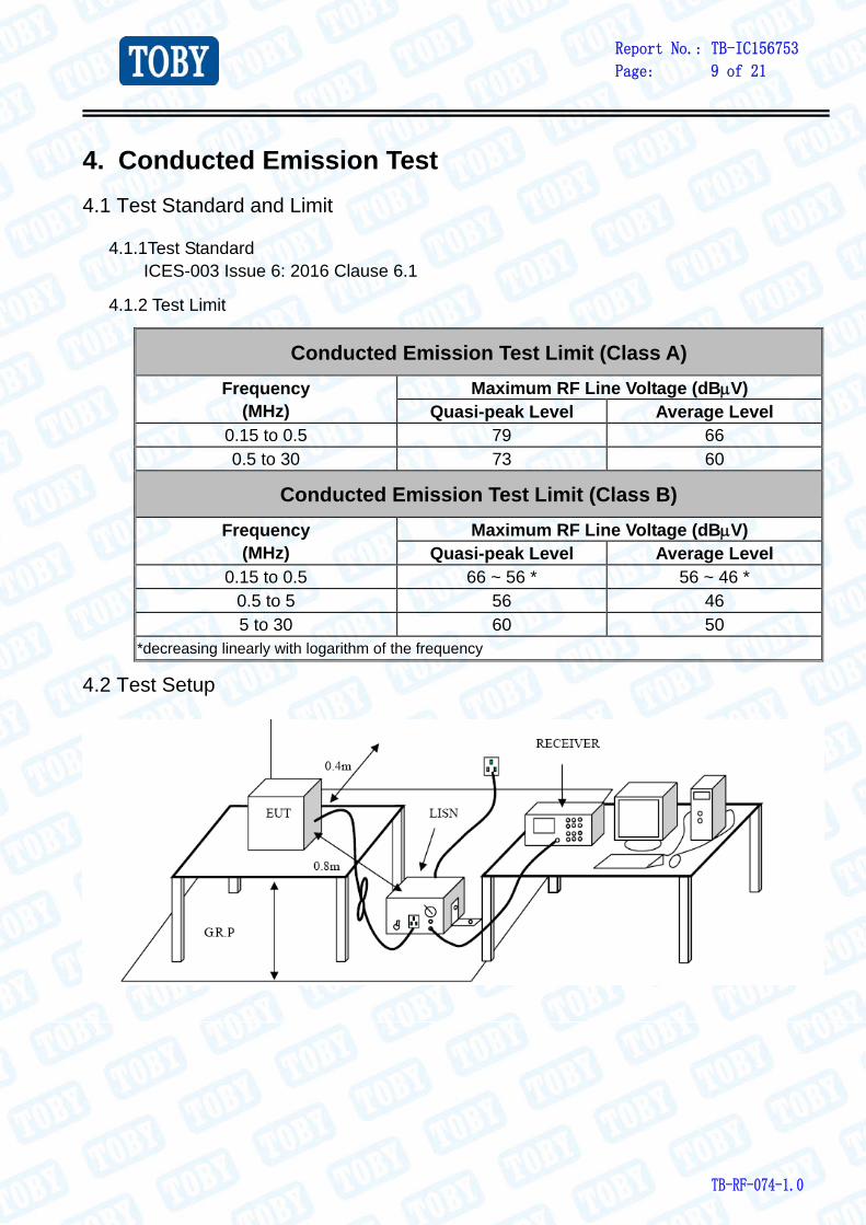
4. Conducted Emission Test
4.1 Test Standard and Limit
4.1.1Test Standard ICES-003 Issue 6: 2016 Clause 6.1
4.1.2 Test Limit
Conducted Emission Test Limit (Class A)
Frequency (MHz)
Maximum RF Line Voltage (dBV) Quasi-peak Level Average Level
0.15 to 0.5 79 66 0.5 to 30 73 60
Conducted Emission Test Limit (Class B)
Frequency (MHz)
Maximum RF Line Voltage (dBV) Quasi-peak Level Average Level
0.15 to 0.5 66 ~ 56 * 56 ~ 46 * 0.5 to 5 56 46 5 to 30 60 50
*decreasing linearly with logarithm of the frequency
4.2 Test Setup

Report No.: TB-IC156753
Page: 10 of 21
TB-RF-074-1.0
4.3 Test Procedure
The EUT was placed 0.15 meters from the horizontal ground plane with EUT being connected to the power mains through a line impedance stabilization network (LISN). All other support equipments powered from additional LISN(s). The LISN provide 50 Ohm/ 50uH of coupling impedance for the measuring instrument. The cables shall be insulated (by up to 15 cm) from the horizontal ground reference plane, and shall be folded back and forth in the center forming a bundle 30 to 40 cm long.
I/O cables that are not connected to a peripheral shall be bundled in the center. The end of the cable may be terminated, if required, using the correct terminating impedance. The overall length shall not exceed 1 m. LISN at least 80 cm from nearest part of EUT chassis. The bandwidth of EMI test receiver is set at 9kHz, and the test frequency band is from 0.15MHz to 30MHz.
4.4 Test Data
This test is not applicable.

Report No.: TB-IC156753
Page: 11 of 21
TB-RF-074-1.0
5. Radiated Emission Test
5.1 Test Standard and Limit
5.1.1 Test Standard ICES-003 Issue 6: 2016 Clause 6.2
5.1.2 Test Limit
Radiated Emission Test Limit bellow 1 GHz (Class A)
Frequency MHz
Field Strengths Limits dB(V/m)
30 ~ 88 49.0 88 ~ 216 53.5
216 ~ 960 56.4 960 ~ 1000 59.5
Radiated Emission Test Limit bellow 1 GHz (Class B)
Frequency MHz
Field Strengths Limits dB(V/m)
30 ~ 88 40.0 88 ~ 216 43.5
216 ~ 960 46.0 960 ~ 1000 54.0
* The lower limit shall apply at the transition frequency.
* The test distance is 3m.
Radiated Emission Test Limit above 1 GHz (Class A)
Frequency (MHz) Field Strengths Limits
(dBV/m) Linear Average Detector Peak Detector
>1000 59.5 79.5
Radiated Emission Test Limit above 1 GHz (Class B)
Frequency (MHz) Field Strengths Limits
(dBV/m) Linear Average Detector Peak Detector
>1000 54 74
Report No.: TB-IC156753
Page: 12 of 21
TB-RF-074-1.0
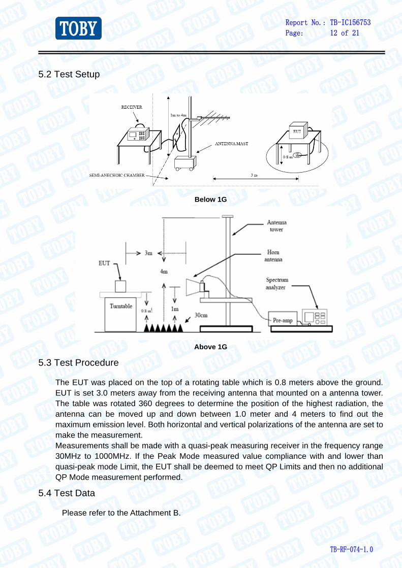
5.2 Test Setup
Below 1G
Above 1G
5.3 Test Procedure
The EUT was placed on the top of a rotating table which is 0.8 meters above the ground. EUT is set 3.0 meters away from the receiving antenna that mounted on a antenna tower. The table was rotated 360 degrees to determine the position of the highest radiation, the antenna can be moved up and down between 1.0 meter and 4 meters to find out the maximum emission level. Both horizontal and vertical polarizations of the antenna are set to make the measurement. Measurements shall be made with a quasi-peak measuring receiver in the frequency range 30MHz to 1000MHz. If the Peak Mode measured value compliance with and lower than quasi-peak mode Limit, the EUT shall be deemed to meet QP Limits and then no additional QP Mode measurement performed.
5.4 Test Data
Please refer to the Attachment B.
Report No.: TB-IC156753
Page: 13 of 21
TB-RF-074-1.0
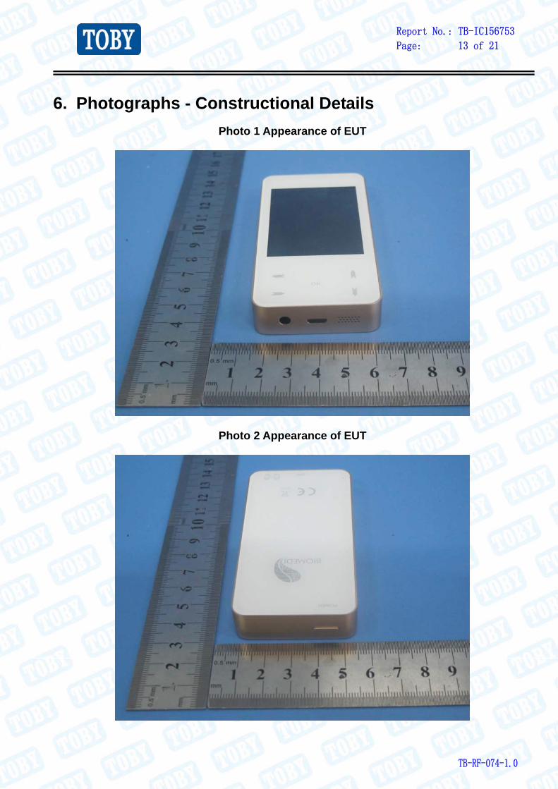
6. Photographs - Constructional Details
Photo 1 Appearance of EUT
Photo 2 Appearance of EUT
Report No.: TB-IC156753
Page: 14 of 21
TB-RF-074-1.0
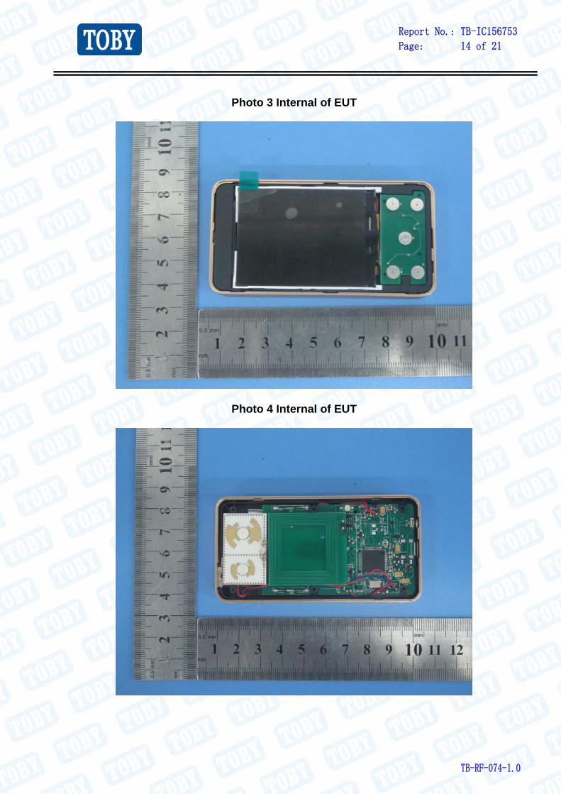
Photo 3 Internal of EUT
Photo 4 Internal of EUT
Report No.: TB-IC156753
Page: 15 of 21
TB-RF-074-1.0
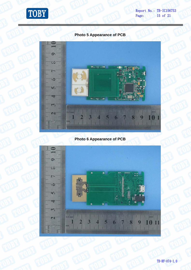
Photo 5 Appearance of PCB
Photo 6 Appearance of PCB

Report No.: TB-IC156753
Page: 16 of 21
TB-RF-074-1.0
Photo 7 Appearance of Battery

Report No.: TB-IC156753
Page: 17 of 21
TB-RF-074-1.0
7. Photographs - Test Setup
Radiated Emission Test Setup—Below 1G
Radiated Emission Test Setup—Below 1G

Report No.: TB-IC156753
Page: 18 of 21
TB-RF-074-1.0
Attachment B--Radiated Emission Test Data ----Below 1G
Temperature: 25 ℃ Relative Humidity: 55%
Test Voltage: DC 5V
Ant. Pol. Horizontal
Test Mode: Mode 1
Remark:
Emission Level= Read Level+ Correct Factor
Report No.: TB-IC156753
Page: 19 of 21
TB-RF-074-1.0
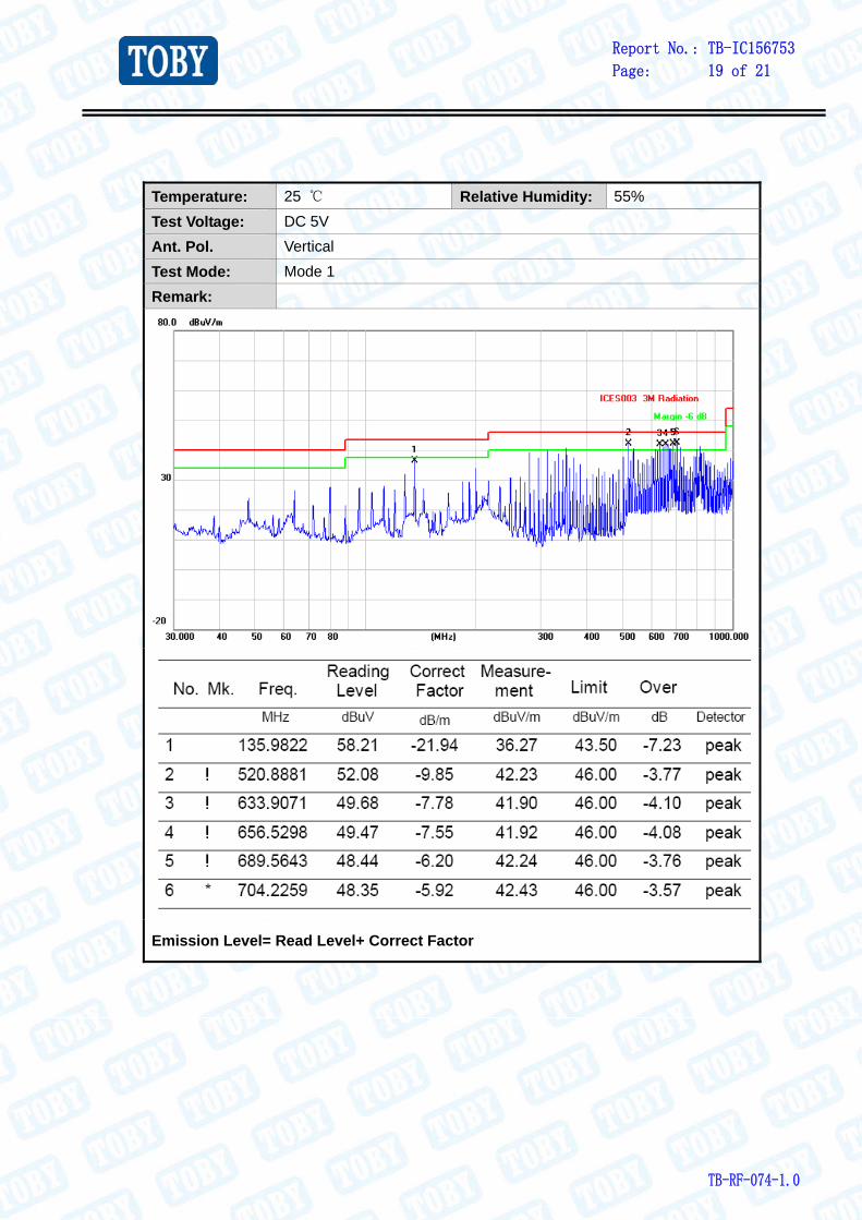
Temperature: 25 ℃ Relative Humidity: 55%
Test Voltage: DC 5V
Ant. Pol. Vertical
Test Mode: Mode 1
Remark:
Emission Level= Read Level+ Correct Factor

Report No.: TB-IC156753
Page: 20 of 21
TB-RF-074-1.0
Temperature: 25 ℃ Relative Humidity: 55%
Test Voltage: DC 3.7V
Ant. Pol. Horizontal
Test Mode: Mode 1
Remark:
Emission Level= Read Level+ Correct Factor

Report No.: TB-IC156753
Page: 21 of 21
TB-RF-074-1.0
Temperature: 25 ℃ Relative Humidity: 55%
Test Voltage: DC 3.7V
Ant. Pol. Vertical
Test Mode: Mode 1
Remark:
Emission Level= Read Level+ Correct Factor
-----END OF REPORT-----