shipmechs - kivi · shipmechs “ship mechatronics ... a real steerable thruster is mounted in a...
TRANSCRIPT

1 © Wärtsilä 16 June 2009
SHIPMECHSHow Mechatronic solutions can help to improve overall
performance
16 June 2009
Teus van BeekLeo de Vries
2 © Wärtsilä 16 June 2009
Content
• Background of Wärtsilä Energy Core • SHIPMECHS project proposal• Examples of applications• Conclusions

3 © Wärtsilä 16 June 2009
Definition of Wärtsilä Energy Core
• By combining these areas and treating them together as an integrated solution, a truly efficient ship operation can be a chieved.
OPERATION
MACHINERY
PROPULSION
SHIPDESIGN
Integration byAutomation
Evolution of ship efficiency
4 © Wärtsilä 16 June 2009
Definition of Wärtsilä Energy Core
• Economical• Environmentally sound
Fossil Renewable
ENERGYINPUT TOTHE SHIP
ENERGYCONVERSION
PowerPropulsionP A
Energy conversion

5 © Wärtsilä 16 June 2009
Definition of Wärtsilä Energy Core
G1
M2
M3M1
G3
WHR
G2
FC
+ -
PREFF ControlEEFF HREFF
Advanced Energy Management (AEM)
Ship design is playing a key role in definingAnd facilitating our solutions
Efficiency controls
Key areas of development
6 © Wärtsilä 16 June 2009
SHIPMECHS
“SHIP MECHATRONICS”Mechatronics = combination of 'Mechanics' and 'Electronics ‘1.3 MEuro, 24 months (July 2009 – June 2011)
Operators:• Koninklijke Wagenborg B.V.• Heerema Marine Contractors Nederland B.V.Industrial partners:• Wärtsilä Netherlands B.V.• VAF Instruments B.V.Knowledge providers:• Eindhoven University of Technology• Avans Hogeschool
National co-operation project

7 © Wärtsilä 16 June 2009
SHIPMECHS
Main objective is to provide a solution for better ship management
capable of providing the required information and advisory for enabling a better ship management, in terms:
• Improved safety & reliability
• fuel saving & emission reductions
• predictive operating costs
Objective
8 © Wärtsilä 16 June 2009
SHIPMECHS
• Innovative solution for ship management;
• New sensors and control solutions;
• Real-time advisory system for onboard and onshore support;
• A mock-up training simulator for operating crew and office support.
project results

9 © Wärtsilä 16 June 2009
SHIPMECHS
• How to provide real-time advice on ship manoeuvring, ship operation and ship maintenance that enables better ship management?
• a combination of mechatronics and intelligence can be the answer
Challenge
10 © Wärtsilä 16 June 2009
1. Introduction: Applications Large Offshore & Heavy lift
Thialf6 x 5,5 MWRetractableDockwise Heavy Lift 2 x 5,5 MW
Covered by Lips Modular Thruster

11 © Wärtsilä 16 June 2009
1. Introduction: Steerable thrusters power range
0
1000
2000
3000
4000
5000
6000
7000
8000
175 200 225 250 275 300 1000 1510 2500 2510 3500 5000
Thruster type
Pow
er (
kW)
|------------------------------------|-----------------------------------|LCT LMT
•Lips Compact Thrusters•Lips Modular Thrusters
•Can mounted •Underwater mounting•Retractable•Containerized
12 © Wärtsilä 16 June 2009
1. Introduction Health thruster
What can effect a thruster?
• Seal damage: water content in lub.oil reduces the life time of bearings and gears• Inadequate lubrication: due to late filter / oil change• Overloading of the thruster• External impacts
• Eventually this leads to early wear of gears and bearings• Wear particles spread through the unit and affect other “healthy”components
THE HEALTH OF THE THRUSTER SLOWLY BUT STEADILY DETE RIORATES EVENTUALLY THE CONSEQUENCES WILL LEAD TO
• Unplanned maintenance / repairs• Replacement parts• Loss of redundancy (Class)• Docking

13 © Wärtsilä 16 June 2009
1. Introduction: Operators interest
Uninterrupted reliable operations, so no:
• Loss of hire > 150.000 USD / Day
• Docking > 1 Milj USD
• Replacement parts
• Mounting / De-mounting
• Loss of redundancy (Class)• Loss of Confidence
14 © Wärtsilä 16 June 2009
1. Introduction from alarming…
• Temperature alarms– lubrication
– steering
• Pressure alarms
– pumps– steering motors– filters
• Level alarms– gearboxes– header tanks
• Rely on expertise on board, Wärtsilä’s service• Alarm: (too?) late, not source related

15 © Wärtsilä 16 June 2009
1. Introduction … to monitoring…
• Detect early changes in behavior • Establish trend lines• Optimize usage of equipment
By adding sensors to system:• Accelerometers-> vibrations gears/bearings
– damage raceway / roller element of bearing
• Saturation sensors-> moisture in oil– Expectation is that (sea) water leakage can
be early detected– Water has mayor influence on the lifetime of
gears/bearings and on the characteristics of oil
• Contamination sensors-> particles in oil– Keep track on the cleanliness of the oil– Particles have major influence on the
lifetime of thruster components
Source: FAG
Source: C.C. Jensen A/S
16 © Wärtsilä 16 June 2009
1. Introduction: Definitions
Condition Monitoring System (CMS):is a real-time machinery parameter measurement & signal processing system.
Offline: Measurements and data collection are manual performed (not automatically) by an engineer on regularly basis with a hand held measurement device
Online:Measurements and data collection are performed automatically on a continuous basis without human intervention. The systems are connected with a local network.
Online with remote access:Thruster and operational parameters can be monitored and analyzed by experts on different locations.

17 © Wärtsilä 16 June 2009
1. Introduction: Definitions
Condition Based Maintenance (CBM):
constitutes a set of maintenance processes and capabilities derived from real-time assessment of the machinery condition obtained from embedded sensors and on-line signal processing.
Prognostics:is an automated CBM system, which predicts the remaining machinery service life under defined operational conditions.
18 © Wärtsilä 16 June 2009
1. Introduction: CBM Engines
Condition Based Maintenance (CBM) and related services are well established offerings for Wärtsilä diesel engines.
For the propulsion systems Wärtsilä has now introduced a Condition Monitoring System (CMS) for steerable thrusters that supports its CBM Services.

19 © Wärtsilä 16 June 2009
1. Introduction: Benefits CMS
Current situation and solutions:
• Classification societies/owners cope with failing machinery, by demanding and applying redundancy in propulsion devices
->CMS can detect deteriorating components
• Inspected via regular checks 2.5-5 years by Class– During the periodic dry-docking the main focus of the Classification Societies is on the
inspection of machinery elements. These regular checks carried out may visualize a changing condition. During these checks a preventive maintenance will be executed
->CMS can continuously show the condition
• Protect machinery with the aid of alarms– The alarm will only indicate if the condition has reached an unacceptable level. In this
case the system must be stopped for repair.-> CMS will indicate a changing condition and shall give an early warning
• If something fails, we have to rely on service reports from Wärtsilä service engineers or expertise on board
-> CMS experts will perform an analysis and diagnosis which will contribute the service department
20 © Wärtsilä 16 June 2009
3. CMS Thruster parameters
Water ingress, by saturation sensor
Particles in oil, by contamination sensor
Vibrations of bearings and gears by accelerometers
RPM, by mobile system
Accelerometer
in thruster
Contamination sensor
in lubrication system
Saturation sensor in lubrication system
Temperature of oil, by temperature sensors Temperature
sensor in thruster

21 © Wärtsilä 16 June 2009
3. CMS Operational parameters
22 © Wärtsilä 16 June 2009
3. CMS Development
Past
Alarms
• pressure• oil• temperature• level
Today
Monitoring/Diagnosis
Early detection of deteriorating components:• vibrations
•damage raceway / roller element of bearing
• moisture•water affects gears/bearings
• particles•keep track on contamination/oil quality
Tomorrow
Prognostics
• combine signals, remaining lifetime• historical/statistical database • usage
WarningAlarm
Par
amet
er
time
23 © Wärtsilä 16 June 2009
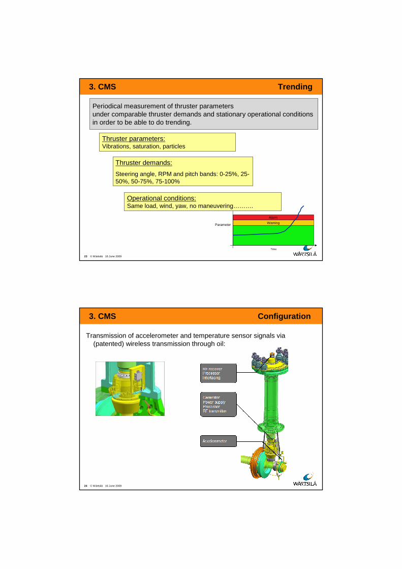
Thruster parameters:Vibrations, saturation, particles
3. CMS Trending
Time
Warning
Alarm
Parameter
Periodical measurement of thruster parameters under comparable thruster demands and stationary operational conditions in order to be able to do trending.
Thruster demands:
Steering angle, RPM and pitch bands: 0-25%, 25-50%, 50-75%, 75-100%
Operational conditions:Same load, wind, yaw, no maneuvering……….
24 © Wärtsilä 16 June 2009
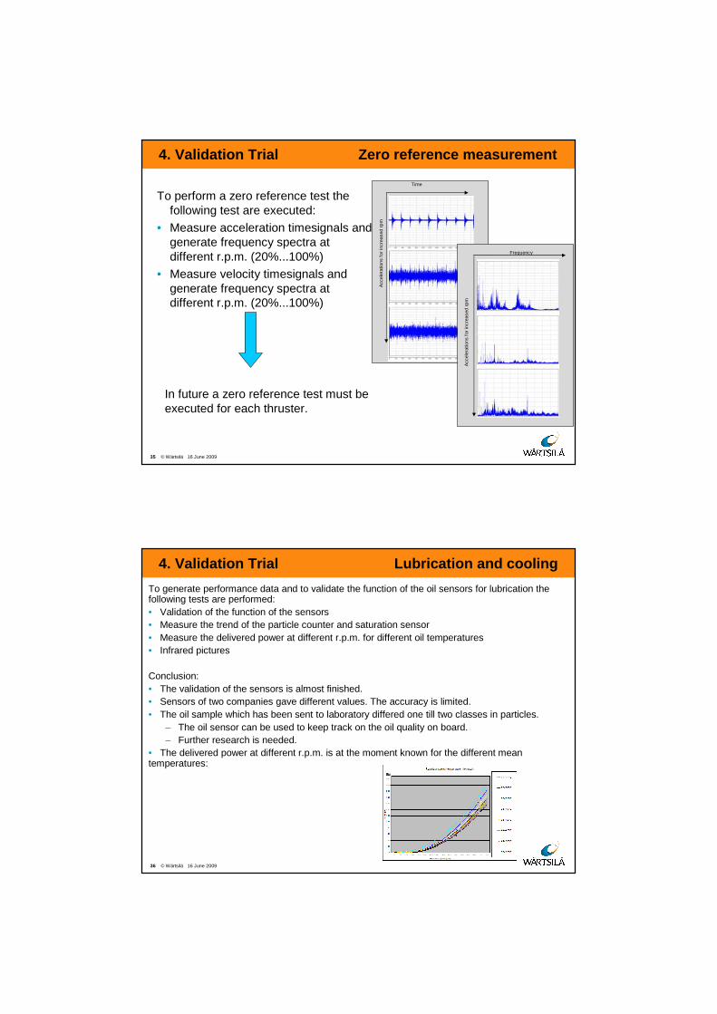
3. CMS Configuration
Transmission of accelerometer and temperature sensor signals via(patented) wireless transmission through oil:

25 © Wärtsilä 16 June 2009
3. CMS Features
Accelerometer to be as close as possible at gear or bearing location in order to:• Avoid loss of signal due to attenuation• Earlier detection of vibrations• Locate the problem
Smart power generator:• Permanent magnets• No batteries
Mobile system:• Dedicated reliable electronics• Software can be uploaded wireless (when thruster is running)
Wireless:• Avoid cabling and connectors• No slip rings
Stationary system:• Dedicated reliable electronics• Convert digital information into signals: vibrations, rpm, temperatures
26 © Wärtsilä 16 June 2009
3. CMS Online system overview
Measurements and data collection are performed automatically on a continuous basis without human intervention. The systems are connected with a local area network. The online system for automatic trending is developed as follows:

27 © Wärtsilä 16 June 2009
3. CMS Offline system components
Wireless Transmission System:• 6 Accelerometers:
– Current line drive 3.5mA closed current range 0.3Hz – 10kHz , 5.35µA/ms^-²
• 2 Temperature Sensors:
– Passive 4-20mA , -5˚C..100˚C, tolerance +-2.2%• RPM:
– TTL pulse on rotary speed frequency
Oil Sensors:• Contamination Sensor:
– Number of particles per 100ml (ISO Class) for four indicated sizes ( ISO 4,6,14 and 21) Sequential active 4-20mA signal
• Saturation Sensor:– Saturation of water in Oil 0%..100%
Active 4-20mA signal
28 © Wärtsilä 16 June 2009
3. CMS Onl ine system components
Online Thruster System
per thruster
Vibroweb-XP:• Performing specified vibration measuring tasks
– FFT in Flat File (ODX)
– RMS values (Modbus/TCP)
– Alarms/warnings (Modbus/TCP)
WAGO Programmable Controller:• Necessary for interface between Vibroweb-XP and
Stationary System
• I/O and conversion to physical values of analogue signals– Oil sensors
– Temperature sensors
– Other analogue signals
• Serial Communication (optional)– Controls
• RPM (demanded) • Pitch (demanded)• Steering angle (demanded) • Load • Direction of Rotation
• Publish Physical Values– Parameter values (Modbus/TCP)
• Alarms and Warning– Reading set points from IPC (Modbus/TCP)– Publish Alarms & Warnings (Modbus/TCP)

29 © Wärtsilä 16 June 2009
3. CMS Online System Central Overview
Online Central System IPC:• Gathering per Thruster
– Parameter Values (Modbus/TCP)
– Alarms/Warnings (Modbus/TCP)
– Vibration Data (FTP)
• Gathering Nautical Equipment Data– GPS • Echo • Heading • Motions
• Publish Data– Parameter Values (OPC)
– Alarms/Warnings (OPC)
– Vibration Data (Flat Files)
• Data Storage– All data for 2 years
• Human Machine Interface– Client level (restricted possibilities)
• Manual Input of events (maintenance)
– Several Wärtsilä levels
• Change set points
• Analyzing stored data
30 © Wärtsilä 16 June 2009
3. CMS Online system with remote access
Thruster and operational parameters can be monitored and analyzed by experts on different locations. Remote access and automatic trending is developed as follows:

31 © Wärtsilä 16 June 2009
4. Validation Trial Demonstrator/Thialf
A real steerable thruster is mounted in a test rig, which is called a demonstrator, and equipped with the wireless transmission system in order to:
1. Validate the wireless transmission for sensors within thruster.
2. Measure attenuation to find best location of accelerometers.
3. Get a zero reference measurement for vibrations4. Get performance data for the lubrication system,
and validate the condition monitoring oil sensors.5. Learn from online monitoring (remote access,
automatic trending)
The steerable thruster o/b of the Thialf is tested on functionality.
32 © Wärtsilä 16 June 2009
4. Validation Trial Transmission
To validate the wireless transmission within the thruster the next tests are performed:
• Checked the signal on errors in communication at different conditions
• Programmed a known frequency in the mobile system inside the thruster and sent this wireless to the stationary system
• Measured acceleration time signals
The tests were successful. The quality of communication is good.
System A 500 Hz timesignal FFT of 500 Hz timesignal

33 © Wärtsilä 16 June 2009
4. Validation Trial Attenuation
To measure the damping of the signals, measured by the accelerometers the following tests and analysis are executed:
• Measure acceleration timesignals in the thruster (sensors 8A and 8B) and on top of the thruster at different r.p.m. (ch0-ch5)
• Compare timesignals and frequency spectra
8A
8B
ch0-ch5
34 © Wärtsilä 16 June 2009
4. Validation Trial Attenuation
Conclusion: Attenuation is clearly visible in the timesignal. Measuring as close as possible at element level results in the lowest possible attenuation of acceleration through metal and joints (peek from signal B is much higher than the peek from signal A).
Acc
eler
atio
n
Time
A
B
35 © Wärtsilä 16 June 2009
4. Validation Trial Zero reference measurement
To perform a zero reference test the following test are executed:
• Measure acceleration timesignals and generate frequency spectra at different r.p.m. (20%...100%)
• Measure velocity timesignals and generate frequency spectra at different r.p.m. (20%...100%)
In future a zero reference test must be executed for each thruster.
Acc
eler
atio
ns f
or in
crea
sed
rpm
Time
Frequency
Acc
eler
atio
ns f
or in
crea
sed
rpm
36 © Wärtsilä 16 June 2009
4. Validation Trial Lub rication and cooling
To generate performance data and to validate the function of the oil sensors for lubrication the following tests are performed:• Validation of the function of the sensors • Measure the trend of the particle counter and saturation sensor • Measure the delivered power at different r.p.m. for different oil temperatures• Infrared pictures
Conclusion:• The validation of the sensors is almost finished. • Sensors of two companies gave different values. The accuracy is limited. • The oil sample which has been sent to laboratory differed one till two classes in particles.
– The oil sensor can be used to keep track on the oil quality on board.– Further research is needed.
• The delivered power at different r.p.m. is at the moment known for the different mean temperatures:

37 © Wärtsilä 16 June 2009
4. Validation Trial Remote access
To learn from on-line trending, the thruster is regularly running at different r.p.m. and different oil temperatures in order to test automatic trending and remote access.
Conclusion:
Automatic trending and remote access is working
38 © Wärtsilä 16 June 2009
4. Validation Trial o/b me asurements Thialf
One steerable thruster o/b of the Semi Submersible
Crane Vessel Thialf is equipped with CMS.
It is running for on year and functional tested 1st May.
Conclusion:
• Wireless transmission works for azimuth angles (0,90,180 and 270º)
• Temperature sensors and accelerometers are functioning.
Acc
eler
atio
n
Time Frequency
Acc
eler
atio
n
Azimuth angle 0º

39 © Wärtsilä 16 June 2009
5. Conclusions From CMS to CBM
From Condition Monitoring to Condition Based Mainte nance:
� Asses the condition of components or system
� Dedicated electronics for wireless transmission sys tem works
� Measure as close as possible to bearings as demonst rated is needed because of to much noise
� Online thruster system and remote access works
� Experience is gained for thruster under no load (demonstrator); the system o/b of the Thialf functions with load
� Results give a fundamental basis for the definitive product specification
Eventually this approach allows to perform condition based maintenance
40 © Wärtsilä 16 June 2009
7. Questions
Questions?