shock absorbers - weforma · nm/h min. - max.kg min. - max.kg min. - max.kg min ... we-m 1,5 x 3 75...
TRANSCRIPT

www.weforma.com15.4.2016
Mega-Line WE-M 1,5
SVF
m
Dec
eler
atio
n Te
chno
logy
Shock Absorbers
ONLINECalculation + 2D / 3D CAD Download
www.weforma.com15.4.2016
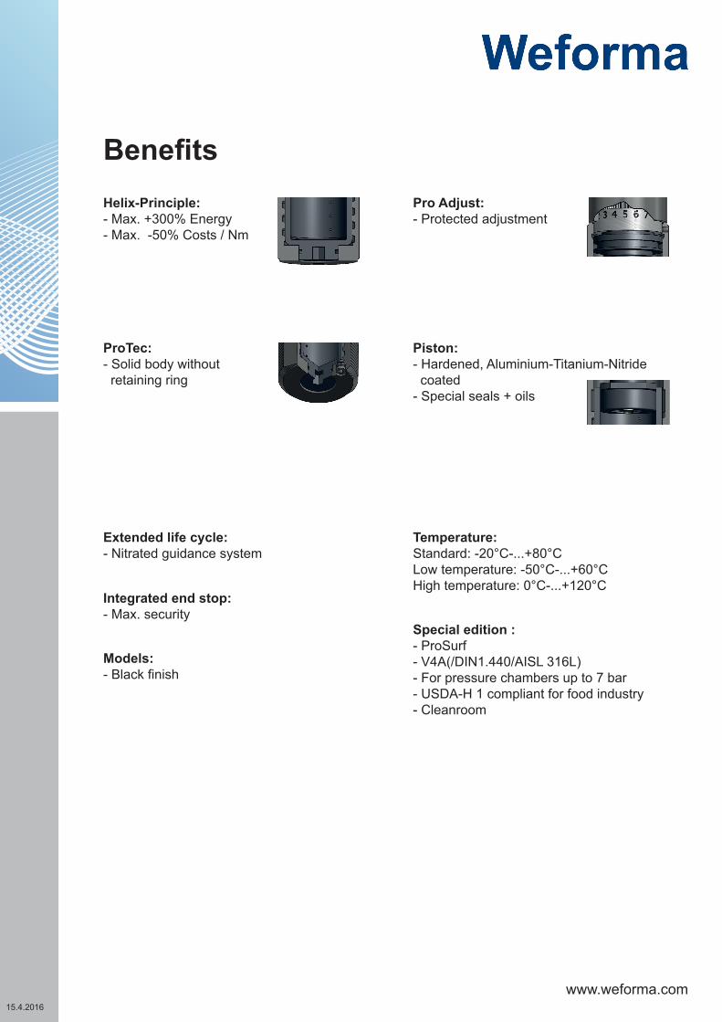
Helix-Principle:- Max. +300% Energy- Max. -50% Costs / Nm
Models:- Black finish
Special edition :- ProSurf- V4A(/DIN1.440/AISL 316L)- For pressure chambers up to 7 bar- USDA-H 1 compliant for food industry- Cleanroom
Temperature:Standard: -20°C-...+80°CLow temperature: -50°C-...+60°CHigh temperature: 0°C-...+120°C
Piston: - Hardened, Aluminium-Titanium-Nitride coated - Special seals + oils
Extended life cycle: - Nitrated guidance system
ProTec: - Solid body without retaining ring
Integrated end stop: - Max. security
Pro Adjust:- Protected adjustment
Benefits

www.weforma.com15.4.2016
mm Nm/HB (max.) Nm/h (max.) Nm/h min. - max.kg min. - max.kg min. - max.kg min. - max.kg
min. - max.kg
WE-M 1,5 x 1 25 870 261.000 450.000 30 - 250 150 - 21.000 6.200 - 240.000
- -
WE-M 1,5 x 2 50 1350 340.000 544.000 45 - 430 300 - 26.000 10.800 - 330.000
- -
WE-M 1,5 x 3 75 2100 420.000 670.000 70 - 670 450 - 27.600 16.800 - 500.000
- -
GW* A B ø E ø E1 F1 F2 SWmm mm mm mm mm mm mm
WE-M 1,5 x 1 M 45 x 2 148 89 39,6 31 18 13 41WE-M 1,5 x 2 M 45 x 2 198 114 39,6 31 18 13 41WE-M 1,5 x 3 M 45 x 2 248 139 39,6 31 18 13 41
SW
GW ØE
ØE1
ØE1
B
A
HB
F2
F1
AS*
A*
Hub
Gewinde
StrokeEnergy absorption Effective mass
Constant load* External tank** -0 (very soft) -1 (soft) -2 (medium) -3 (hard) -4 (very hard)
Series Code Threads Example
1,5 K M 42x1,5 WE-M 1,5x1-1K1,5 H M 42x2 WE-M 1,5x1-1H1,5 L M 45x1,5 WE-M 1,5x1-1L1,5 U 1 3/4-12 UNF WE-M 1,5x1-1U
Series Code Threads Example
1,5X1 M 45x2 WE-M 1,5X1-1-VA1,5X1 L M 45x1,5 WE-M 1,5X1-1L-VA1,5X1 U 1 3/4-12 UNF WE-M 1,5X1-1U-VA
1,5X2 M 45x2 WE-M 1,5X2-1-VA1,5X2 L M 45x1,5 WE-M 1,5X2-1L-VA1,5X2 U 1 3/4-12 UNF WE-M 1,5X2-1U-VA
1,5X3 M 45x2 WE-M 1,5X3-1-VA1,5X3 L M 45x1,5 WE-M 1,5X3-1L-VA1,5X3 U 1 3/4-12 UNF WE-M 1,5X3-1U-VA
PERFOMANCE
DIMENSIONS
SPECIAL THREAD - from stock STAINLESS STEEL - from stock
Technical data at + 20°C
*A: PU / AS: SteelAdd “A / AS” after the part no.
www.weforma.com15.4.2016
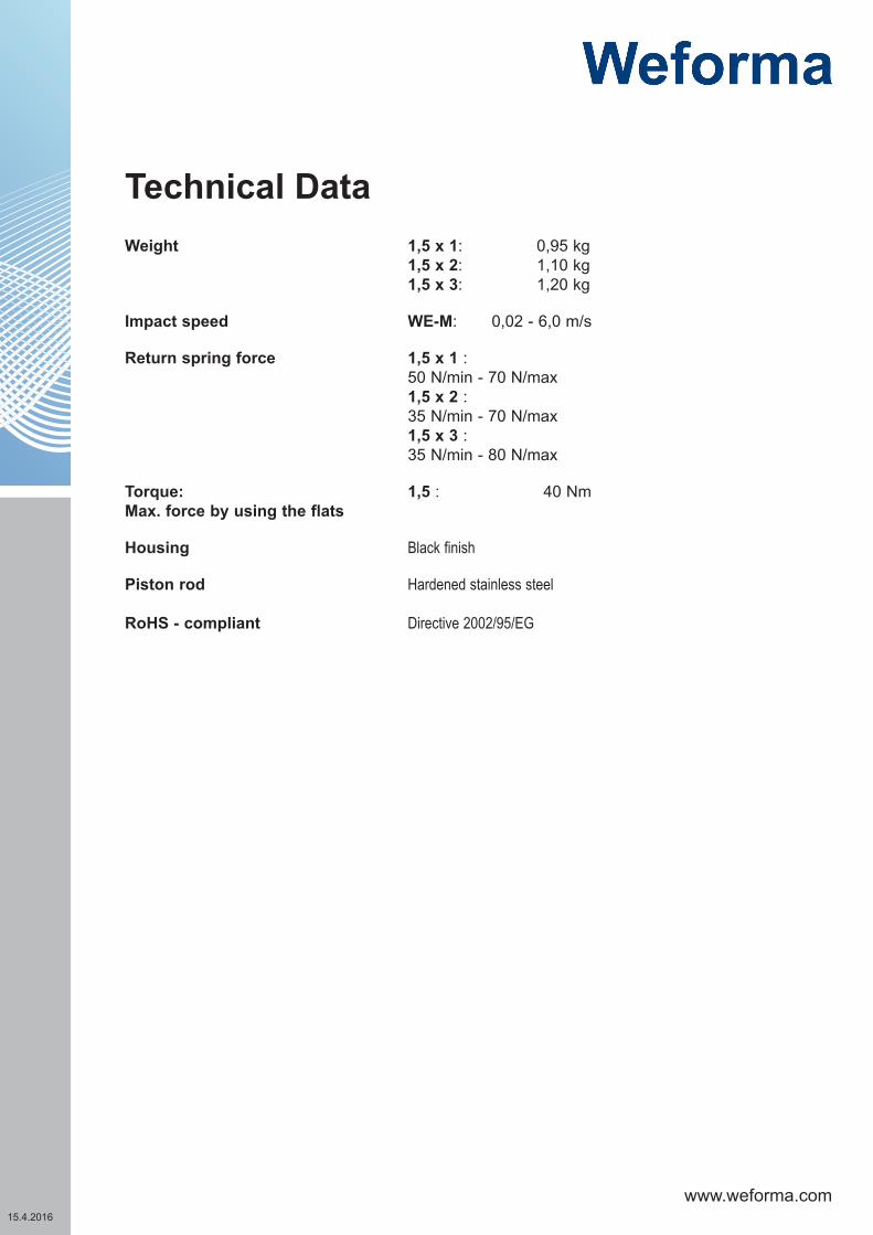
Weight 1,5 x 1: 0,95 kg 1,5 x 2: 1,10 kg1,5 x 3: 1,20 kg
Impact speed WE-M: 0,02 - 6,0 m/s
Return spring force 1,5 x 1 :50 N/min - 70 N/max1,5 x 2 :35 N/min - 70 N/max1,5 x 3 :35 N/min - 80 N/max
Torque: Max. force by using the flats
1,5 : 40 Nm
Housing Black finish
Piston rod
RoHS - compliant
Hardened stainless steel
Directive 2002/95/EG
Technical Data

www.weforma.com15.4.2016
GW* A B max C D E F G H Code
mm mm mm mm mm mm mm mm
1,5 x 1 M 45 x 2 148 64 12,5 25 80 56 M8 58 S24015
1,5 x 2 M 45 x 2 198 89 12,5 25 80 56 M8 58 S24015
1,5 x 3 M 45 x 2 248 114 12,5 25 80 56 M8 58 S24015
inklusive
Code.: S24012
Code.: S24014
Code.: S24018ØA
GW B
D
C
GW
ØF
E
GW
J
G
ØI ØH
GW ØAmm
Bmm Code
M42x1,5 54 8 S24012KM45x1,5 54 8 S24012LM45x2 54 8 S240121 3/4-12UNF 54 8 S24012UEdelstahlM42x1,5 54 8 S24012K-VAM45x1,5 54 8 S24012L-VAM45x2 54 8 S24012VA
GW ØFmm
Emm
Dmm
Cmm Code
M42x1,5 9 12 43 55 S24014KM45x1,5 9 12 42 55 S24014LM45x2 9 12 42 55 S240141 3/4-12 UNF 9 12 42 55 S24014U
GW ØImm
ØHmm
Gmm
Jmm Code
M42x1,5 49 57 65 35 S24018KM45x1,5 49 57 65 35 S24018LM45x2 47 54 65 35 S24018
D
C B max
A
F
E
H
GW
G
AccessoriesLock nut
Square flange
Stop limit nut
Foot mounting
www.weforma.com15.4.2016
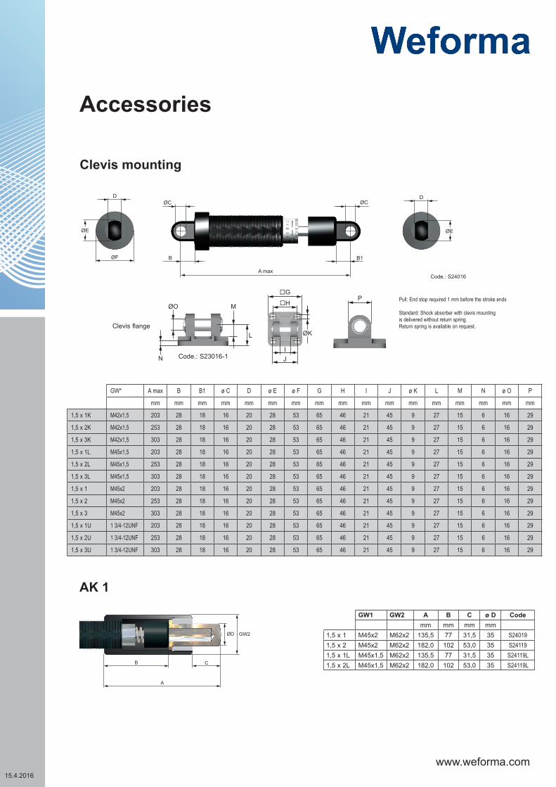
GW* A max B B1 ø C D ø E ø F G H I J ø K L M N ø O P
mm mm mm mm mm mm mm mm mm mm mm mm mm mm mm mm mm
1,5 x 1K M42x1,5 203 28 18 16 20 28 53 65 46 21 45 9 27 15 6 16 29
1,5 x 2K M42x1,5 253 28 18 16 20 28 53 65 46 21 45 9 27 15 6 16 29
1,5 x 3K M42x1,5 303 28 18 16 20 28 53 65 46 21 45 9 27 15 6 16 29
1,5 x 1L M45x1,5 203 28 18 16 20 28 53 65 46 21 45 9 27 15 6 16 29
1,5 x 2L M45x1,5 253 28 18 16 20 28 53 65 46 21 45 9 27 15 6 16 29
1,5 x 3L M45x1,5 303 28 18 16 20 28 53 65 46 21 45 9 27 15 6 16 29
1,5 x 1 M45x2 203 28 18 16 20 28 53 65 46 21 45 9 27 15 6 16 29
1,5 x 2 M45x2 253 28 18 16 20 28 53 65 46 21 45 9 27 15 6 16 29
1,5 x 3 M45x2 303 28 18 16 20 28 53 65 46 21 45 9 27 15 6 16 29
1,5 x 1U 1 3/4-12UNF 203 28 18 16 20 28 53 65 46 21 45 9 27 15 6 16 29
1,5 x 2U 1 3/4-12UNF 253 28 18 16 20 28 53 65 46 21 45 9 27 15 6 16 29
1,5 x 3U 1 3/4-12UNF 303 28 18 16 20 28 53 65 46 21 45 9 27 15 6 16 29
D D
ØE
ØF B
A max
B1
ØC ØC
ØE
ØO
N
M
L ØK
H
G
IJ
P
Clevis flange
Code.: S23016-1
Code.: S24016
GW1 GW2ØD
CB
A
GW1 GW2 A B C ø D Codemm mm mm mm
1,5 x 1 M45x2 M62x2 135,5 77 31,5 35 S240191,5 x 2 M45x2 M62x2 182,0 102 53,0 35 S241191,5 x 1L M45x1,5 M62x2 135,5 77 31,5 35 S24119L1,5 x 2L M45x1,5 M62x2 182,0 102 53,0 35 S24119L
AK 1
Clevis mounting
Accessories
Pull: End stop required 1 mm before the stroke ends
Standard: Shock absorber with clevis mounting is delivered without return spring.Return spring is available on request.

www.weforma.com15.4.2016
ØE
ø Emm Code
1,5 x 1 60 S24017
1,5 x 2 80 S24117
1,5 x 3 80 S24217
25
R1/8
138
R1/8
8,5
Ø43
AT 1
WE-M 1,5
WE-M 1,5 x 2 - 1ATFor shock absorbers without return spring
WE-M 1,5 x 2 - 1 ATFFor shock absorbers with return spring
WM-AT 1For external Tanks
Code.: 23810
AccessoriesProtection bellow
Benefits: Optimum cooling and therefore higher energy absorption per hour“
External Tanks

www.weforma.com15.4.2016
Adjustment: The adjustment cann be done with the hexagonal recess in the bottom of the housing or with the adjustment ring at the piston rod side.
Adjustment: It is not allowed to adjust the shock absorber in operation conditions or during the operation.
0 = low damping8 = high damping
In order to adjust the shock absorber set the adjustment screw to „6“ if the velocity is <1,3 m/s or to „4“ if the velocity is >1,3 m/s.Internal damage to the shock absorber can occur, if not adjusted in gradual increments. Do not drive in the final position under full load. If the damping is not sufficient, increase continously by rotating the adjustment to the next higher number. Maximum damping is achieved, when the highest number on the scale is reached.If the mass impacts exessively hard on the shock absorber (stop cap) the damping should be reduced by rotation of the adjustment to the next smaller number. Minimum damping is at „0“ setting.Secure the adjustment with the threaded pin. A hexagonal key is supplied for this purpose.For sizes 1,25 and bigger the threaded pin is on the flats in the region of the front adjustment.

www.weforma.com15.4.2016
Clevis mounting
Stroke
Lock nut
Foot mounting
Stroke
Stop limit nut
Threads
Lock nut
Stroke FlangeStroke
Foot mounting Clevis mounting
Installation
Installation with flangeInstallation with stop limit nut

www.weforma.com15.4.2016
FundamentalsShock absorbers may under no circumstances be:
-painted -welded -held with clamps -used on pull*
(exception: clevis mounting)
In hazardous environments (dirt, humidity, oil) shock absorbers must be protected against damage and failure with the necessary accessory. If several shock absorbers are used on the same application, the deceleration has to be distributed equally. The “Torque” (PERFORMANCE) indicates the maximum force by using the flats. The Weforma catalogue shows technical data with both minimum and maximum values. If a product is to be used in continuous operation and within a range of 20% from the minimum and maximum values shown, then written confirmation of suitability of use from Weforma is necessary.
Safety InstructionsBefore installation, commissioning, servicing and repair the data sheet is to be noticed. This work may only be performed by trained, introduced staff.
Electric connections according to the suitable national regulation. For Germany: VDE regulation VD E0100
Before all repair and servicing works the energy supplies (main switch, etc.) have to be switched off! Moreover, measures are necessary to prevent an unintential reconnect. For example, a warning sign “service works“ or “maintenance work“, applied to the switch.
Designated use
Check before installation and make sure the type name on the shock absorber or on the packaging is corresponding with delivery note. Industrial shock absorbers are maintenance-free and ready for installation.
• Temperature influence: at higher temperatures the shock absorber characteristic will change.• Movable loads have to be protected during the installation and maintenance against unintentional processes.• In operation outside the allowed temperature range, the shock absorber can lose his function. Due to heat radiation
don’t paint the shock absorber.• Fluids, gases and a dirty environment can affect or destroy the sealing system of the shock absorber. The result could
be a failure malfunction. Piston rod and sealing system has to be protected against fluids, gases and a dirty environ-ment.
• Damages at the piston rod can destroy the sealing system. Don’t grease or oil the piston rod.• Avoid traction forces on the piston rod to present internal damages.• The shock absorber can be pulled out of the construction during the impact.The construction needs to be able to resist
the max counterforce. Sufficient security must be calculated. The maximum counterforces performed in the calculation program can vary from the really appearing counter forces, because these are based on theoretical values.

www.weforma.com15.4.2016
Integrated end-stopUp to the Mega-Line series 1,5 the shock absorbers are provided with an integrated end-stop. If the integrated end-stop is used the remaining energy before end of stroke must not be higher than 10% of the total energy. For all models which are used as an emergency stop an external fixed stop is necessary.
Installation situation
The installation situation is any, however always in such a way that the complete shock absorber stroke can be used. The shock absorbers must be mounted like that the forces in centerinke about the piston rod are initiated. The maximum angle out of centre amounts to 2 °.
Liability
Due to the number of possible uses of our products and the conditions of use that lie outside of our scope of influence, we accept no liability as to whether the purchase object is suitable for the Client‘s intended purpose. The verification to this effect, in particular the verification as to whether the purcha-se object is suitable for the planned use, is the responsibility of the Client alone, unless expressly agreed otherwise in writing.
For the reasons we accept no liability for the suitability of the purchase object for the purpose intended by the Client, except in cases of intent or gross negligence.
With damages, the not designated use and from high-handed, in these instructions do not originate to intended interventions, any guarantee and liability claim goes out towards the manufacturer.
Guarantee
By non-use of the original spare parts the guarantee claim goes out.
Environment protection
By the exchange from damaged parts is to be respected to a proper disposal.
Important information