shop-pdp.net · page ii 1.4.34 .ifnb directive 1-43 1.4.35 .ifidn directive 1-44 1.4.36 .ifdif...
TRANSCRIPT

ASxxxx Assemblers
and
ASLINK Relocating Linker
Version 5.30 January 2019
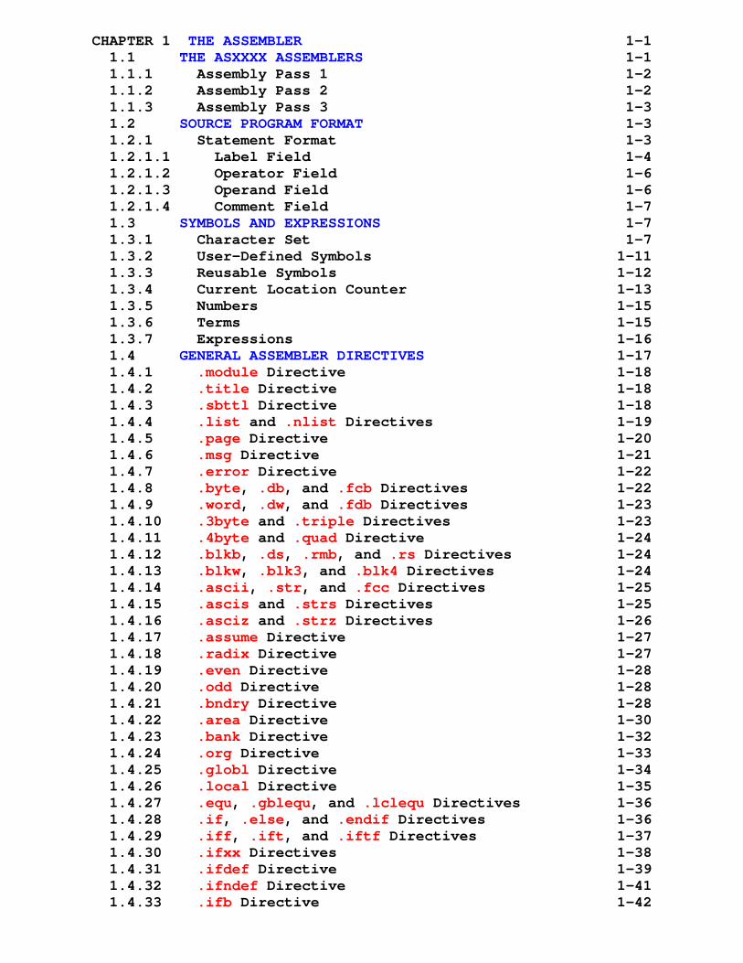
CHAPTER 1 THE ASSEMBLER 1-1 1.1 THE ASXXXX ASSEMBLERS 1-1 1.1.1 Assembly Pass 1 1-2 1.1.2 Assembly Pass 2 1-2 1.1.3 Assembly Pass 3 1-3 1.2 SOURCE PROGRAM FORMAT 1-3 1.2.1 Statement Format 1-3 1.2.1.1 Label Field 1-4 1.2.1.2 Operator Field 1-6 1.2.1.3 Operand Field 1-6 1.2.1.4 Comment Field 1-7 1.3 SYMBOLS AND EXPRESSIONS 1-7 1.3.1 Character Set 1-7 1.3.2 User-Defined Symbols 1-11 1.3.3 Reusable Symbols 1-12 1.3.4 Current Location Counter 1-13 1.3.5 Numbers 1-15 1.3.6 Terms 1-15 1.3.7 Expressions 1-16 1.4 GENERAL ASSEMBLER DIRECTIVES 1-17 1.4.1 .module Directive 1-18 1.4.2 .title Directive 1-18 1.4.3 .sbttl Directive 1-18 1.4.4 .list and .nlist Directives 1-19 1.4.5 .page Directive 1-20 1.4.6 .msg Directive 1-21 1.4.7 .error Directive 1-22 1.4.8 .byte, .db, and .fcb Directives 1-22 1.4.9 .word, .dw, and .fdb Directives 1-23 1.4.10 .3byte and .triple Directives 1-23 1.4.11 .4byte and .quad Directive 1-24 1.4.12 .blkb, .ds, .rmb, and .rs Directives 1-24 1.4.13 .blkw, .blk3, and .blk4 Directives 1-24 1.4.14 .ascii, .str, and .fcc Directives 1-25 1.4.15 .ascis and .strs Directives 1-25 1.4.16 .asciz and .strz Directives 1-26 1.4.17 .assume Directive 1-27 1.4.18 .radix Directive 1-27 1.4.19 .even Directive 1-28 1.4.20 .odd Directive 1-28 1.4.21 .bndry Directive 1-28 1.4.22 .area Directive 1-30 1.4.23 .bank Directive 1-32 1.4.24 .org Directive 1-33 1.4.25 .globl Directive 1-34 1.4.26 .local Directive 1-35 1.4.27 .equ, .gblequ, and .lclequ Directives 1-36 1.4.28 .if, .else, and .endif Directives 1-36 1.4.29 .iff, .ift, and .iftf Directives 1-37 1.4.30 .ifxx Directives 1-38 1.4.31 .ifdef Directive 1-39 1.4.32 .ifndef Directive 1-41 1.4.33 .ifb Directive 1-42
Page ii
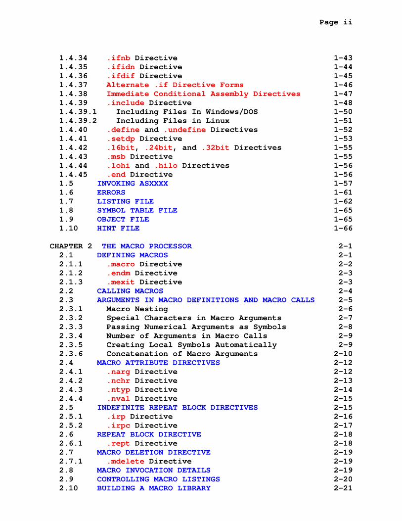
1.4.34 .ifnb Directive 1-43 1.4.35 .ifidn Directive 1-44 1.4.36 .ifdif Directive 1-45 1.4.37 Alternate .if Directive Forms 1-46 1.4.38 Immediate Conditional Assembly Directives 1-47 1.4.39 .include Directive 1-48 1.4.39.1 Including Files In Windows/DOS 1-50 1.4.39.2 Including Files in Linux 1-51 1.4.40 .define and .undefine Directives 1-52 1.4.41 .setdp Directive 1-53 1.4.42 .16bit, .24bit, and .32bit Directives 1-55 1.4.43 .msb Directive 1-55 1.4.44 .lohi and .hilo Directives 1-56 1.4.45 .end Directive 1-56 1.5 INVOKING ASXXXX 1-57 1.6 ERRORS 1-61 1.7 LISTING FILE 1-62 1.8 SYMBOL TABLE FILE 1-65 1.9 OBJECT FILE 1-65 1.10 HINT FILE 1-66
CHAPTER 2 THE MACRO PROCESSOR 2-1 2.1 DEFINING MACROS 2-1 2.1.1 .macro Directive 2-2 2.1.2 .endm Directive 2-3 2.1.3 .mexit Directive 2-3 2.2 CALLING MACROS 2-4 2.3 ARGUMENTS IN MACRO DEFINITIONS AND MACRO CALLS 2-5 2.3.1 Macro Nesting 2-6 2.3.2 Special Characters in Macro Arguments 2-7 2.3.3 Passing Numerical Arguments as Symbols 2-8 2.3.4 Number of Arguments in Macro Calls 2-9 2.3.5 Creating Local Symbols Automatically 2-9 2.3.6 Concatenation of Macro Arguments 2-10 2.4 MACRO ATTRIBUTE DIRECTIVES 2-12 2.4.1 .narg Directive 2-12 2.4.2 .nchr Directive 2-13 2.4.3 .ntyp Directive 2-14 2.4.4 .nval Directive 2-15 2.5 INDEFINITE REPEAT BLOCK DIRECTIVES 2-15 2.5.1 .irp Directive 2-16 2.5.2 .irpc Directive 2-17 2.6 REPEAT BLOCK DIRECTIVE 2-18 2.6.1 .rept Directive 2-18 2.7 MACRO DELETION DIRECTIVE 2-19 2.7.1 .mdelete Directive 2-19 2.8 MACRO INVOCATION DETAILS 2-19 2.9 CONTROLLING MACRO LISTINGS 2-20 2.10 BUILDING A MACRO LIBRARY 2-21

Page iii
2.10.1 .mlib Macro Directive 2-21 2.10.2 .mcall Macro Directive 2-22 2.11 EXAMPLE MACRO CROSS ASSEMBLERS 2-24
CHAPTER 3 THE LINKER 3-1 3.1 ASLINK RELOCATING LINKER 3-1 3.2 INVOKING ASLINK 3-2 3.3 LIBRARY PATH(S) AND FILE(S) 3-5 3.4 ASLINK PROCESSING 3-6 3.5 ASXXXX VERSION 5.XX (4.XX) LINKING 3-9 3.5.1 Object Module Format 3-9 3.5.2 Header Line 3-10 3.5.3 Module Line 3-10 3.5.4 Merge Mode Line 3-10 3.5.5 Bank Line 3-11 3.5.6 Area Line 3-11 3.5.7 Symbol Line 3-12 3.5.8 T Line 3-12 3.5.9 R Line 3-12 3.5.10 P Line 3-13 3.5.11 24-Bit and 32-Bit Addressing 3-14 3.5.12 ASlink V5.xx (V4.xx) Error Messages 3-14 3.6 ASXXXX VERSION 3.XX LINKING 3-17 3.6.1 Object Module Format 3-17 3.6.2 Header Line 3-18 3.6.3 Module Line 3-18 3.6.4 Area Line 3-18 3.6.5 Symbol Line 3-18 3.6.6 T Line 3-19 3.6.7 R Line 3-19 3.6.8 P Line 3-20 3.6.9 24-Bit and 32-Bit Addressing 3-20 3.6.10 ASlink V3.xx Error Messages 3-21 3.7 HINT FILE FORMAT FOR RELOCATED LISTINGS 3-23 3.8 INTEL IHX OUTPUT FORMAT (16-BIT) 3-25 3.9 INTEL I86 OUTPUT FORMAT (24 OR 32-BIT) 3-27 3.10 MOTOROLA S1-S9 OUTPUT FORMAT (16-BIT) 3-29 3.11 MOTOROLA S2-S8 OUTPUT FORMAT (24-BIT) 3-30 3.12 MOTOROLA S3-S7 OUTPUT FORMAT (32-BIT) 3-31 3.13 TANDY COLOR COMPUTER DISK BASIC FORMAT 3-32
CHAPTER 4 BUILDING ASXXXX AND ASLINK 4-1 4.1 BUILDING ASXXXX AND ASLINK WITH LINUX 4-2 4.2 BUILDING ASXXXX AND ASLINK UNDER CYGWIN 4-2 4.3 BUILDING ASXXXX AND ASLINK WITH DJGPP 4-3 4.4 BUILDING ASXXXX AND ASLINK WITH BORLAND'S TURBO C++ 3.0 4-3 4.4.1 Graphical User Interface 4-4 4.4.2 Command Line Interface 4-4
Page iv
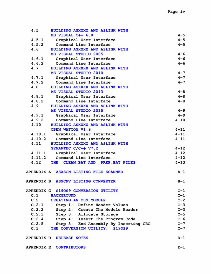
4.5 BUILDING ASXXXX AND ASLINK WITH MS VISUAL C++ 6.0 4-5 4.5.1 Graphical User Interface 4-5 4.5.2 Command Line Interface 4-5 4.6 BUILDING ASXXXX AND ASLINK WITH MS VISUAL STUDIO 2005 4-6 4.6.1 Graphical User Interface 4-6 4.6.2 Command Line Interface 4-6 4.7 BUILDING ASXXXX AND ASLINK WITH MS VISUAL STUDIO 2010 4-7 4.7.1 Graphical User Interface 4-7 4.7.2 Command Line Interface 4-7 4.8 BUILDING ASXXXX AND ASLINK WITH MS VISUAL STUDIO 2013 4-8 4.8.1 Graphical User Interface 4-8 4.8.2 Command Line Interface 4-8 4.9 BUILDING ASXXXX AND ASLINK WITH MS VISUAL STUDIO 2015 4-9 4.9.1 Graphical User Interface 4-9 4.9.2 Command Line Interface 4-10 4.10 BUILDING ASXXXX AND ASLINK WITH OPEN WATCOM V1.9 4-11 4.10.1 Graphical User Interface 4-11 4.10.2 Command Line Interface 4-11 4.11 BUILDING ASXXXX AND ASLINK WITH SYMANTEC C/C++ V7.2 4-12 4.11.1 Graphical User Interface 4-12 4.11.2 Command Line Interface 4-12 4.12 THE _CLEAN.BAT AND _PREP.BAT FILES 4-13
APPENDIX A ASXSCN LISTING FILE SCANNER A-1
APPENDIX B ASXCNV LISTING CONVERTER B-1
APPENDIX C S19OS9 CONVERSION UTILITY C-1 C.1 BACKGROUND C-1 C.2 CREATING AN OS9 MODULE C-2 C.2.1 Step 1: Define Header Values C-3 C.2.2 Step 2: Create The Module Header C-3 C.2.3 Step 3: Allocate Storage C-5 C.2.4 Step 4: Insert The Program Code C-6 C.2.5 Step 5: End Assembly By Inserting CRC C-7 C.3 THE CONVERSION UTILITY: S19OS9 C-7
APPENDIX D RELEASE NOTES D-1
APPENDIX E CONTRIBUTORS E-1
Page v
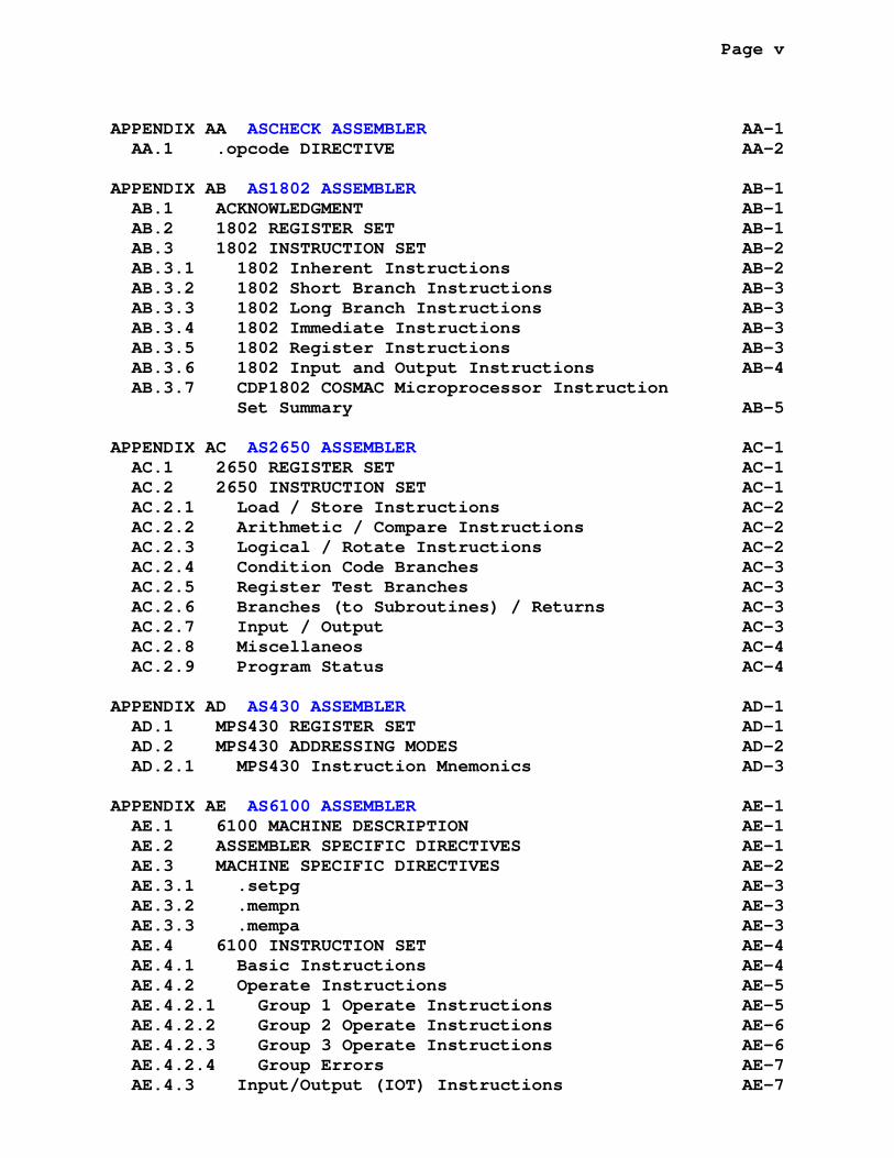
APPENDIX AA ASCHECK ASSEMBLER AA-1 AA.1 .opcode DIRECTIVE AA-2
APPENDIX AB AS1802 ASSEMBLER AB-1 AB.1 ACKNOWLEDGMENT AB-1 AB.2 1802 REGISTER SET AB-1 AB.3 1802 INSTRUCTION SET AB-2 AB.3.1 1802 Inherent Instructions AB-2 AB.3.2 1802 Short Branch Instructions AB-3 AB.3.3 1802 Long Branch Instructions AB-3 AB.3.4 1802 Immediate Instructions AB-3 AB.3.5 1802 Register Instructions AB-3 AB.3.6 1802 Input and Output Instructions AB-4 AB.3.7 CDP1802 COSMAC Microprocessor Instruction Set Summary AB-5
APPENDIX AC AS2650 ASSEMBLER AC-1 AC.1 2650 REGISTER SET AC-1 AC.2 2650 INSTRUCTION SET AC-1 AC.2.1 Load / Store Instructions AC-2 AC.2.2 Arithmetic / Compare Instructions AC-2 AC.2.3 Logical / Rotate Instructions AC-2 AC.2.4 Condition Code Branches AC-3 AC.2.5 Register Test Branches AC-3 AC.2.6 Branches (to Subroutines) / Returns AC-3 AC.2.7 Input / Output AC-3 AC.2.8 Miscellaneos AC-4 AC.2.9 Program Status AC-4
APPENDIX AD AS430 ASSEMBLER AD-1 AD.1 MPS430 REGISTER SET AD-1 AD.2 MPS430 ADDRESSING MODES AD-2 AD.2.1 MPS430 Instruction Mnemonics AD-3
APPENDIX AE AS6100 ASSEMBLER AE-1 AE.1 6100 MACHINE DESCRIPTION AE-1 AE.2 ASSEMBLER SPECIFIC DIRECTIVES AE-1 AE.3 MACHINE SPECIFIC DIRECTIVES AE-2 AE.3.1 .setpg AE-3 AE.3.2 .mempn AE-3 AE.3.3 .mempa AE-3 AE.4 6100 INSTRUCTION SET AE-4 AE.4.1 Basic Instructions AE-4 AE.4.2 Operate Instructions AE-5 AE.4.2.1 Group 1 Operate Instructions AE-5 AE.4.2.2 Group 2 Operate Instructions AE-6 AE.4.2.3 Group 3 Operate Instructions AE-6 AE.4.2.4 Group Errors AE-7 AE.4.3 Input/Output (IOT) Instructions AE-7
Page vi
APPENDIX AF AS61860 ASSEMBLER AF-1 AF.1 ACKNOWLEDGMENT AF-1 AF.2 61860 REGISTER SET AF-1 AF.3 PROCESSOR SPECIFIC DIRECTIVES AF-2 AF.4 61860 INSTRUCTION SET AF-2 AF.4.1 Load Immediate Register AF-3 AF.4.2 Load Accumulator AF-3 AF.4.3 Store Accumulator AF-3 AF.4.4 Move Data AF-3 AF.4.5 Exchange Data AF-4 AF.4.6 Stack Operations AF-4 AF.4.7 Block Move Data AF-4 AF.4.8 Block Exchange Data AF-4 AF.4.9 Increment and Decrement AF-5 AF.4.10 Increment/Decrement with Load/Store AF-5 AF.4.11 Fill AF-6 AF.4.12 Addition and Subtraction AF-6 AF.4.13 Shift Operations AF-6 AF.4.14 Boolean Operations AF-6 AF.4.15 Compare AF-7 AF.4.16 CPU Control AF-7 AF.4.17 Absolute Jumps AF-7 AF.4.18 Relative Jumps AF-8 AF.4.19 Calls AF-8 AF.4.20 Input and output AF-8 AF.4.21 Unknown Commands AF-9
APPENDIX AG AS6500 ASSEMBLER AG-1 AG.1 ACKNOWLEDGMENT AG-1 AG.2 6500 REGISTER SET AG-2 AG.3 6500 INSTRUCTION SET AG-2 AG.3.1 Processor Specific Directives AG-3 AG.3.2 65xx Core Inherent Instructions AG-3 AG.3.3 65xx Core Branch Instructions AG-3 AG.3.4 65xx Core Single Operand Instructions AG-4 AG.3.5 65xx Core Double Operand Instructions AG-4 AG.3.6 65xx Core Jump and Jump to Subroutine Instructions AG-4 AG.3.7 65xx Core Miscellaneous X and Y Register Instructions AG-4 AG.3.8 65F11 and 65F12 Specific Instructions AG-5 AG.3.9 65C00/21 and 65C29 Specific Instructions AG-5 AG.3.10 65C02, 65C102, and 65C112 Specific Instructions AG-6
APPENDIX AH AS6800 ASSEMBLER AH-1 AH.1 6800 REGISTER SET AH-1 AH.2 6800 INSTRUCTION SET AH-1 AH.2.1 Inherent Instructions AH-2
Page vii
AH.2.2 Branch Instructions AH-2 AH.2.3 Single Operand Instructions AH-3 AH.2.4 Double Operand Instructions AH-4 AH.2.5 Jump and Jump to Subroutine Instructions AH-4 AH.2.6 Long Register Instructions AH-5
APPENDIX AI AS6801 ASSEMBLER AI-1 AI.1 .hd6303 DIRECTIVE AI-1 AI.2 6801 REGISTER SET AI-1 AI.3 6801 INSTRUCTION SET AI-1 AI.3.1 Inherent Instructions AI-2 AI.3.2 Branch Instructions AI-3 AI.3.3 Single Operand Instructions AI-3 AI.3.4 Double Operand Instructions AI-5 AI.3.5 Jump and Jump to Subroutine Instructions AI-5 AI.3.6 Long Register Instructions AI-6 AI.3.7 6303 Specific Instructions AI-6
APPENDIX AJ AS6804 ASSEMBLER AJ-1 AJ.1 6804 REGISTER SET AJ-1 AJ.2 6804 INSTRUCTION SET AJ-1 AJ.2.1 Inherent Instructions AJ-2 AJ.2.2 Branch Instructions AJ-2 AJ.2.3 Single Operand Instructions AJ-2 AJ.2.4 Jump and Jump to Subroutine Instructions AJ-2 AJ.2.5 Bit Test Instructions AJ-3 AJ.2.6 Load Immediate data Instruction AJ-3 AJ.2.7 6804 Derived Instructions AJ-3
APPENDIX AK AS68(HC)05 ASSEMBLER AK-1 AK.1 .6805 DIRECTIVE AK-1 AK.2 .hc05 DIRECTIVE AK-1 AK.3 THE .__.CPU. VARIABLE AK-1 AK.4 6805 REGISTER SET AK-2 AK.5 6805 INSTRUCTION SET AK-2 AK.5.1 Control Instructions AK-3 AK.5.2 Bit Manipulation Instructions AK-3 AK.5.3 Branch Instructions AK-3 AK.5.4 Read-Modify-Write Instructions AK-4 AK.5.5 Register\Memory Instructions AK-4 AK.5.6 Jump and Jump to Subroutine Instructions AK-5
APPENDIX AL AS68(HC[S])08 ASSEMBLER AL-1 AL.1 PROCESSOR SPECIFIC DIRECTIVES AL-1 AL.1.1 .hc08 Directive AL-1 AL.1.2 .hcs08 Directive AL-2 AL.1.3 .6805 Directive AL-2 AL.1.4 .hc05 Directive AL-2 AL.1.5 The .__.CPU. Variable AL-3

Page viii
AL.2 68HC(S)08 REGISTER SET AL-3 AL.3 68HC(S)08 INSTRUCTION SET AL-4 AL.3.1 Control Instructions AL-5 AL.3.2 Bit Manipulation Instructions AL-5 AL.3.3 Branch Instructions AL-5 AL.3.4 Complex Branch Instructions AL-5 AL.3.5 Read-Modify-Write Instructions AL-6 AL.3.6 Register\Memory Instructions AL-7 AL.3.7 Double Operand Move Instruction AL-7 AL.3.8 16-Bit <H:X> Index Register Instructions AL-7 AL.3.9 Jump and Jump to Subroutine Instructions AL-7
APPENDIX AM AS6809 ASSEMBLER AM-1 AM.1 6809 REGISTER SET AM-1 AM.2 6809 INSTRUCTION SET AM-1 AM.2.1 Inherent Instructions AM-3 AM.2.2 Short Branch Instructions AM-3 AM.2.3 Long Branch Instructions AM-4 AM.2.4 Single Operand Instructions AM-5 AM.2.5 Double Operand Instructions AM-6 AM.2.6 D-register Instructions AM-6 AM.2.7 Index/Stack Register Instructions AM-7 AM.2.8 Jump and Jump to Subroutine Instructions AM-7 AM.2.9 Register - Register Instructions AM-7 AM.2.10 Condition Code Register Instructions AM-7 AM.2.11 6800 Compatibility Instructions AM-8
APPENDIX AN AS6811 ASSEMBLER AN-1 AN.1 68HC11 REGISTER SET AN-1 AN.2 68HC11 INSTRUCTION SET AN-1 AN.2.1 Inherent Instructions AN-2 AN.2.2 Branch Instructions AN-3 AN.2.3 Single Operand Instructions AN-4 AN.2.4 Double Operand Instructions AN-5 AN.2.5 Bit Manupulation Instructions AN-5 AN.2.6 Jump and Jump to Subroutine Instructions AN-6 AN.2.7 Long Register Instructions AN-6
APPENDIX AO AS68(HC[S])12 ASSEMBLER AO-1 AO.1 PROCESSOR SPECIFIC DIRECTIVES AO-1 AO.1.1 .hc12 Directive AO-1 AO.1.2 .hcs12 Directive AO-1 AO.1.3 The .__.CPU. Variable AO-2 AO.2 68HC(S)12 REGISTER SET AO-2 AO.3 68HC(S)12 INSTRUCTION SET AO-3 AO.3.1 Inherent Instructions AO-4 AO.3.2 Short Branch Instructions AO-5 AO.3.3 Long Branch Instructions AO-5 AO.3.4 Branch on Decrement, Test, or Increment AO-5
Page ix
AO.3.5 Bit Clear and Set Instructions AO-5 AO.3.6 Branch on Bit Clear or Set AO-6 AO.3.7 Single Operand Instructions AO-6 AO.3.8 Double Operand Instructions AO-7 AO.3.9 Move Instructions AO-7 AO.3.10 D-register Instructions AO-7 AO.3.11 Index/Stack Register Instructions AO-8 AO.3.12 Jump and Jump/Call to Subroutine Instructions AO-8 AO.3.13 Other Special Instructions AO-8 AO.3.14 Register - Register Instructions AO-8 AO.3.15 Condition Code Register Instructions AO-9 AO.3.16 M68HC11 Compatibility Mode Instructions AO-9
APPENDIX AP AS6816 ASSEMBLER AP-1 AP.1 68HC16 REGISTER SET AP-1 AP.2 68HC16 INSTRUCTION SET AP-1 AP.2.1 Inherent Instructions AP-3 AP.2.2 Push/Pull Multiple Register Instructions AP-3 AP.2.3 Short Branch Instructions AP-3 AP.2.4 Long Branch Instructions AP-4 AP.2.5 Bit Manipulation Instructions AP-4 AP.2.6 Single Operand Instructions AP-5 AP.2.7 Double Operand Instructions AP-6 AP.2.8 Index/Stack Register Instructions AP-7 AP.2.9 Jump and Jump to Subroutine Instructions AP-7 AP.2.10 Condition Code Register Instructions AP-7 AP.2.11 Multiply and Accumulate Instructions AP-7
APPENDIX AQ AS740 ASSEMBLER AQ-1 AQ.1 ACKNOWLEDGMENT AQ-1 AQ.2 740 REGISTER SET AQ-1 AQ.3 740 INSTRUCTION SET AQ-2 AQ.3.1 Inherent Instructions AQ-3 AQ.3.2 Branch Instructions AQ-3 AQ.3.3 Single Operand Instructions AQ-3 AQ.3.4 Double Operand Instructions AQ-4 AQ.3.5 Jump and Jump to Subroutine Instructions AQ-4 AQ.3.6 Miscellaneous X and Y Register Instructions AQ-4 AQ.3.7 Bit Instructions AQ-4 AQ.3.8 Other Instructions AQ-4
APPENDIX AR AS78K0 ASSEMBLER AR-1 AR.1 PROCESSOR SPECIFIC DIRECTIVES AR-1 AR.1.1 .setdp Directive AR-1 AR.1.2 .xerr Directive AR-2 AR.2 78K/0 REGISTER SET AR-3 AR.3 78K/0 INSTRUCTION SET AR-3 AR.3.1 Inherent Instructions AR-5
Page x
AR.3.2 Branch Instructions AR-5 AR.3.3 Single Operand Instructions AR-6 AR.3.4 Double Operand Instructions AR-6
APPENDIX AS AS78K0S ASSEMBLER AS-1 AS.1 78K/0S REGISTER SET AS-1 AS.2 78K/0S INSTRUCTION SET AS-1 AS.2.1 Inherent Instructions AS-3 AS.2.2 Branch Instructions AS-3 AS.2.3 Single Operand Instructions AS-3 AS.2.4 Double Operand Instructions AS-4
APPENDIX AT AS8008 ASSEMBLER AT-1 AT.1 8008 REGISTER SET AT-1 AT.2 8008 INSTRUCTION SET AT-2 AT.2.1 Instruction Listing AT-2
APPENDIX AU AS8008S ASSEMBLER AU-1 AU.1 8008 REGISTER SET AU-1 AU.2 8008 INSTRUCTION SET AU-2 AU.2.1 Instruction Listing AU-3
APPENDIX AV AS8048 ASSEMBLER AV-1 AV.1 .8048 DIRECTIVE AV-1 AV.2 .8041 DIRECTIVE AV-1 AV.3 .8022 DIRECTIVE AV-2 AV.4 .8021 DIRECTIVE AV-2 AV.5 THE .__.CPU. VARIABLE AV-2 AV.6 8048 REGISTER SET AV-3 AV.7 8048 INSTRUCTION SET AV-4 AV.7.1 Alphabetical Instruction Listing AV-5
APPENDIX AW AS8051 ASSEMBLER AW-1 AW.1 ACKNOWLEDGMENT AW-1 AW.2 8051 REGISTER SET AW-1 AW.3 8051 INSTRUCTION SET AW-2 AW.3.1 Inherent Instructions AW-2 AW.3.2 Move Instructions AW-3 AW.3.3 Single Operand Instructions AW-3 AW.3.4 Two Operand Instructions AW-4 AW.3.5 Call and Return Instructions AW-4 AW.3.6 Jump Instructions AW-4 AW.3.7 Predefined Symbols: SFR Map AW-5 AW.3.8 Predefined Symbols: SFR Bit Addresses AW-6 AW.3.9 Predefined Symbols: Control Bits AW-7
APPENDIX AX AS8085 ASSEMBLER AX-1 AX.1 8085 REGISTER SET AX-1 AX.2 8085 INSTRUCTION SET AX-1
Page xi
AX.2.1 Inherent Instructions AX-2 AX.2.2 Register/Memory/Immediate Instructions AX-2 AX.2.3 Call and Return Instructions AX-2 AX.2.4 Jump Instructions AX-3 AX.2.5 Input/Output/Reset Instructions AX-3 AX.2.6 Move Instructions AX-3 AX.2.7 Other Instructions AX-3 AX.2.8 Unspecified Instructions AX-4 AX.3 UNSPECIFIED OPCODE ARTICLE AX-5
APPENDIX AY AS8X300 ASSEMBLER AY-1 AY.1 PROCESSOR SPECIFIC DIRECTIVES AY-1 AY.1.1 .8x300 Directive AY-1 AY.1.2 .8x305 Directive AY-2 AY.1.3 .liv Directive AY-2 AY.1.4 .riv Directive AY-2 AY.1.5 .fdef Directive AY-2 AY.1.6 .xtnd Directive AY-3 AY.1.7 .xerr Directive AY-3 AY.2 THE 8X300/8X305 MACRO LIBRARY AY-4 AY.2.1 ORG AY-4 AY.2.2 PROC AY-5 AY.2.3 ENTRY AY-5 AY.2.4 CALL, RTN, and CALL_TABLE AY-5 AY.3 8X300 AND 8X305 REGISTER SETS AY-7 AY.4 8X300 AND 8X305 INSTRUCTION SETS AY-8 AY.4.1 Instruction Listing AY-9
APPENDIX AZ AS8XCXXX ASSEMBLER AZ-1 AZ.1 ACKNOWLEDGMENTS AZ-1 AZ.2 AS8XCXXX ASSEMBLER DIRECTIVES AZ-1 AZ.2.1 Processor Selection Directives AZ-1 AZ.2.2 .cpu Directive AZ-2 AZ.2.3 Processor Addressing Range Directives AZ-3 AZ.2.4 The .__.CPU. Variable AZ-3 AZ.2.5 DS80C390 Addressing Mode Directive AZ-4 AZ.2.6 The .msb Directive AZ-4 AZ.3 DS8XCXXX REGISTER SET AZ-6 AZ.4 DS8XCXXX INSTRUCTION SET AZ-6 AZ.4.1 Inherent Instructions AZ-7 AZ.4.2 Move Instructions AZ-7 AZ.4.3 Single Operand Instructions AZ-8 AZ.4.4 Two Operand Instructions AZ-8 AZ.4.5 Call and Return Instructions AZ-9 AZ.4.6 Jump Instructions AZ-9 AZ.5 DS8XCXXX SPECIAL FUNCTION REGISTERS AZ-10 AZ.5.1 SFR Map AZ-10 AZ.5.2 Bit Addressable Registers: Generic AZ-11 AZ.5.3 Bit Addressable Registers: Specific AZ-12
Page xii
AZ.5.4 Optional Symbols: Control Bits AZ-13 AZ.6 DS80C310 SPECIAL FUNCTION REGISTERS AZ-14 AZ.6.1 SFR Map AZ-14 AZ.6.2 Bit Addressable Registers: Generic AZ-15 AZ.6.3 Bit Addressable Registers: Specific AZ-16 AZ.6.4 Optional Symbols: Control Bits AZ-17 AZ.7 DS80C320/DS80C323 SPECIAL FUNCTION REGISTERS AZ-18 AZ.7.1 SFR Map AZ-18 AZ.7.2 Bit Addressable Registers: Generic AZ-19 AZ.7.3 Bit Addressable Registers: Specific AZ-20 AZ.7.4 Optional Symbols: Control Bits AZ-21 AZ.8 DS80C390 SPECIAL FUNCTION REGISTERS AZ-22 AZ.8.1 SFR Map AZ-22 AZ.8.2 Bit Addressable Registers: Generic AZ-23 AZ.8.3 Bit Addressable Registers: Specific AZ-24 AZ.8.4 Optional Symbols: Control Bits AZ-25 AZ.9 DS83C520/DS87C520 SPECIAL FUNCTION REGISTERS AZ-27 AZ.9.1 SFR Map AZ-27 AZ.9.2 Bit Addressable Registers: Generic AZ-28 AZ.9.3 Bit Addressable Registers: Specific AZ-29 AZ.9.4 Optional Symbols: Control Bits AZ-30 AZ.10 DS83C530/DS87C530 SPECIAL FUNCTION REGISTERS AZ-31 AZ.10.1 SFR Map AZ-31 AZ.10.2 Bit Addressable Registers: Generic AZ-32 AZ.10.3 Bit Addressable Registers: Specific AZ-33 AZ.10.4 Optional Symbols: Control Bits AZ-34 AZ.11 DS83C550/DS87C550 SPECIAL FUNCTION REGISTERS AZ-35 AZ.11.1 SFR Map AZ-35 AZ.11.2 Bit Addressable Registers: Generic AZ-37 AZ.11.3 Bit Addressable Registers: Specific AZ-39 AZ.11.4 Optional Symbols: Control Bits AZ-41
APPENDIX BA ASAVR ASSEMBLER BA-1 BA.1 AVR ASSEMBLER NOTES BA-1 BA.1.1 Processor Specific Directives BA-2 BA.1.2 The .__.CPU. Variable BA-3 BA.2 AVR REGISTER SET BA-4 BA.3 AVR INSTRUCTION SET BA-4 BA.3.1 AVR Arithmetic and Logical Instructions BA-6 BA.3.2 AVR Bit and Bit-Test Instructions BA-6 BA.3.3 AVR Skip on Test Instructions BA-7 BA.3.4 AVR Jump/Call/Return Instructions BA-7 BA.3.5 AVR Short Branch Instructions BA-7 BA.3.6 AVR Short Branch Instructions with Bit Test BA-7 BA.3.7 AVR Data Transfer Instructions BA-7
APPENDIX BB ASEZ80 ASSEMBLER BB-1 BB.1 ACKNOWLEDGMENT BB-1 BB.2 PROCESSOR SPECIFIC DIRECTIVES BB-1

Page xiii
BB.2.1 .z80 Directive BB-2 BB.2.2 .adl Directive BB-2 BB.2.3 .msb Directive BB-2 BB.3 EZ80 ADDRESSING AND INSTRUCTIONS BB-4 BB.3.1 Instruction Symbols BB-4 BB.3.2 EZ80 Instructions BB-6 BB.3.3 Arithmetic Instructions BB-9 BB.3.4 Bit Manipulation Instructions BB-10 BB.3.5 Block Transfer and Compare Instructions BB-10 BB.3.6 Exchange Instructions BB-10 BB.3.7 Input/Output Instructions BB-10 BB.3.8 Load Instructions BB-11 BB.3.9 Logical Instructions BB-11 BB.3.10 Processor Control Instructions BB-11 BB.3.11 Program Flow Instructions BB-11 BB.3.12 Shift and Rotate Instructions BB-12
APPENDIX BC ASF2MC8 ASSEMBLER BC-1 BC.1 PROCESSOR SPECIFIC DIRECTIVES BC-1 BC.1.1 .F2MC8L Directive BC-1 BC.1.2 .F2MC8FX Directive BC-1 BC.1.3 The .__.CPU. Variable BC-2 BC.2 F2MC8L/F2MC8FX REGISTERS BC-2 BC.3 F2MC8L/F2MC8FX INSTRUCTION SET BC-3 BC.3.1 Transfer Instructions BC-5 BC.3.2 Operation Instructions BC-5 BC.3.3 Branch/Jump/Call Instructions BC-5 BC.3.4 Other Instructions BC-5
APPENDIX BD ASF8 ASSEMBLER BD-1 BD.1 F8 REGISTERS BD-2 BD.2 F8 INSTRUCTION SET BD-4 BD.2.1 Accumulator Group Instructions BD-5 BD.2.2 Branch Instructions BD-5 BD.2.3 Memory Reference Instructions BD-5 BD.2.4 Address Register Instructions BD-5 BD.2.5 Scratchpad Register Instructions BD-6 BD.2.6 Miscellaneous Instructions BD-6
APPENDIX BE ASGB ASSEMBLER BE-1 BE.1 ACKNOWLEDGEMENT BE-1 BE.2 INTRODUCTION BE-1 BE.3 GAMEBOY REGISTER SET AND CONDITIONS BE-2 BE.4 GAMEBOY INSTRUCTION SET BE-2 BE.4.1 .tile Directive BE-3 BE.4.2 Potentially Controversial Mnemonic Selection BE-4 BE.4.2.1 Auto-Indexing Loads BE-5 BE.4.2.2 Input and Output Operations BE-5 BE.4.2.3 The 'stop' Instruction BE-5

Page xiv
BE.4.3 Inherent Instructions BE-6 BE.4.4 Implicit Operand Instructions BE-6 BE.4.5 Load Instructions BE-6 BE.4.6 Call/Return Instructions BE-7 BE.4.7 Jump Instructions BE-7 BE.4.8 Bit Manipulation Instructions BE-7 BE.4.9 Input and Output Instructions BE-7 BE.4.10 Register Pair Instructions BE-8
APPENDIX BF ASH8 ASSEMBLER BF-1 BF.1 H8/3XX REGISTER SET BF-1 BF.2 H8/3XX INSTRUCTION SET BF-1 BF.2.1 Inherent Instructions BF-2 BF.2.2 Branch Instructions BF-3 BF.2.3 Single Operand Instructions BF-4 BF.2.4 Double Operand Instructions BF-5 BF.2.5 Mov Instructions BF-7 BF.2.6 Bit Manipulation Instructions BF-8 BF.2.7 Extended Bit Manipulation Instructions BF-9 BF.2.8 Condition Code Instructions BF-9 BF.2.9 Other Instructions BF-10 BF.2.10 Jump and Jump to Subroutine Instructions BF-10
APPENDIX BG ASM8C ASSEMBLER BG-1 BG.1 M8C REGISTER SET BG-1 BG.2 M8C ADDRESSING MODES BG-1 BG.3 M8C INSTRUCTION SET BG-2 BG.3.1 Double Operand Arithmetic Instructions BG-2 BG.3.2 Double Operand Logic Instructions BG-3 BG.3.3 Miscellaneous Double Operand Instructions BG-3 BG.3.4 Single Operand Shift/Rotate Instructions BG-3 BG.3.5 Miscellaneous Single Operand Instructions BG-4 BG.3.6 Move Instructions BG-4 BG.3.7 Inherent Instructions BG-5 BG.3.8 Branching Instructions BG-5 BG.3.9 Relative Table Read Instruction BG-5
APPENDIX BH ASPIC ASSEMBLER BH-1 BH.1 PIC ASSEMBLER NOTES BH-1 BH.2 PROCESSOR SPECIFIC DIRECTIVES BH-1 BH.2.1 .pic Directive BH-2 BH.2.2 .picnopic Directive BH-3 BH.2.3 .pic12bit Directive BH-3 BH.2.4 .pic14bit Directive BH-3 BH.2.5 .pic16bit Directive BH-3 BH.2.6 .pic20bit Directive BH-4 BH.2.7 The .__.CPU. Variable BH-4 BH.2.8 .picfix Directive BH-5 BH.2.9 .maxram Directive BH-5
Page xv
BH.2.10 .badram Directive BH-5 BH.2.11 .setdmm Directive BH-6 BH.3 12-BIT OPCODE PIC BH-6 BH.4 14-BIT OPCODE PIC BH-7 BH.5 16-BIT OPCODE PIC BH-9 BH.6 20-BIT ADDRESSING PIC BH-10 BH.7 PIC OPCODES BH-11
APPENDIX BI ASRAB ASSEMBLER BI-1 BI.1 ACKNOWLEDGMENT BI-1 BI.2 PROCESSOR SPECIFIC DIRECTIVES BI-1 BI.2.1 .r2k Directive BI-2 BI.2.2 .hd64 Directive BI-2 BI.2.3 .z80 Directive BI-2 BI.2.4 The .__.CPU. Variable BI-3 BI.3 RABBIT 2000/3000 ADDRESSING AND INSTRUCTIONS BI-4 BI.3.1 Instruction Symbols BI-4 BI.3.2 Rabbit Instructions BI-6 BI.4 Z80/HD64180 ADDRESSING AND INSTRUCTIONS BI-8 BI.4.1 Inherent Instructions BI-9 BI.4.2 Implicit Operand Instructions BI-9 BI.4.3 Load Instruction BI-10 BI.4.4 Call/Return Instructions BI-10 BI.4.5 Jump and Jump to Subroutine Instructions BI-10 BI.4.6 Bit Manipulation Instructions BI-11 BI.4.7 Interrupt Mode and Reset Instructions BI-11 BI.4.8 Input and Output Instructions BI-11 BI.4.9 Register Pair Instructions BI-11 BI.4.10 HD64180 Specific Instructions BI-12
APPENDIX BJ ASSCMP ASSEMBLER BJ-1 BJ.1 SC/MP REGISTER SET BJ-1 BJ.2 SC/MP ADDRESSING MODES BJ-1 BJ.3 SC/MP INSTRUCTION SET BJ-2 BJ.3.1 Memory Reference Instructions BJ-2 BJ.3.2 Immediate Instructions BJ-2 BJ.3.3 Extension Register Instructions BJ-3 BJ.3.4 Memory Increment/Decrement Instructions BJ-3 BJ.3.5 Transfer Instructions BJ-3 BJ.3.6 Pointer Register Move Instructions BJ-3 BJ.3.7 Shift, Rotate, Serial I/O Instructions BJ-4 BJ.3.8 Single-Byte Miscellaneous Instructions BJ-4 BJ.3.9 Double-Byte Miscellaneous Instruction BJ-4
APPENDIX BK ASST6 ASSEMBLER BK-1 BK.1 ST6 REGISTER SET BK-1 BK.2 ST6 INSTRUCTION SET BK-1 BK.2.1 Inherent Instructions BK-2 BK.2.2 Conditional Branch Instructions BK-2
Page xvi
BK.2.3 Bit Manipulation Instructions BK-2 BK.2.4 Single Operand Instructions BK-2 BK.2.5 Double Operand Instructions BK-3 BK.2.6 Call to Subroutine and Jump Instructions BK-3 BK.2.7 Load and Store Instructions BK-3
APPENDIX BL ASST7 ASSEMBLER BL-1 BL.1 ST7 REGISTER SET BL-1 BL.2 ST7 INSTRUCTION SET BL-1 BL.2.1 Inherent Instructions BL-4 BL.2.2 Conditional Branch Instructions BL-4 BL.2.3 Bit Test and Branch Instructions BL-4 BL.2.4 Bit Manipulation Instructions BL-5 BL.2.5 Single Operand Instructions BL-5 BL.2.6 Double Operand Instructions BL-5 BL.2.7 Call to Subroutine and Jump Instructions BL-5
APPENDIX BM ASST8 ASSEMBLER BM-1 BM.1 ST8 REGISTER SET BM-1 BM.2 ST8 INSTRUCTION SET BM-1 BM.2.1 Inherent Instructions BM-5 BM.2.2 Conditional Branch Instructions BM-5 BM.2.3 Bit Test and Branch Instructions BM-5 BM.2.4 Bit Manipulation Instructions BM-5 BM.2.5 Single Operand Instructions BM-6 BM.2.6 Double Operand Instructions BM-7 BM.2.7 Call to Subroutine and Jump Instructions BM-7
APPENDIX BN ASZ8 ASSEMBLER BN-1 BN.1 Z8 REGISTER SET BN-1 BN.2 Z8 INSTRUCTION SET BN-1 BN.2.1 Load Instructions BN-2 BN.2.2 Arithmetic Instructions BN-3 BN.2.3 Logical Instructions BN-3 BN.2.4 Program Control Instructions BN-3 BN.2.5 Bit Manipulation Instructions BN-3 BN.2.6 Block Transfer Instructions BN-3 BN.2.7 Rotate and Shift Instructions BN-3 BN.2.8 Cpu Control Instructions BN-4
APPENDIX BO ASZ80 ASSEMBLER BO-1 BO.1 .z80 DIRECTIVE BO-1 BO.2 .hd64 DIRECTIVE BO-1 BO.3 THE .__.CPU. VARIABLE BO-2 BO.4 Z80 REGISTER SET AND CONDITIONS BO-2 BO.5 Z80 INSTRUCTION SET BO-3 BO.5.1 Inherent Instructions BO-4 BO.5.2 Implicit Operand Instructions BO-4 BO.5.3 Load Instruction BO-5
Page xvii
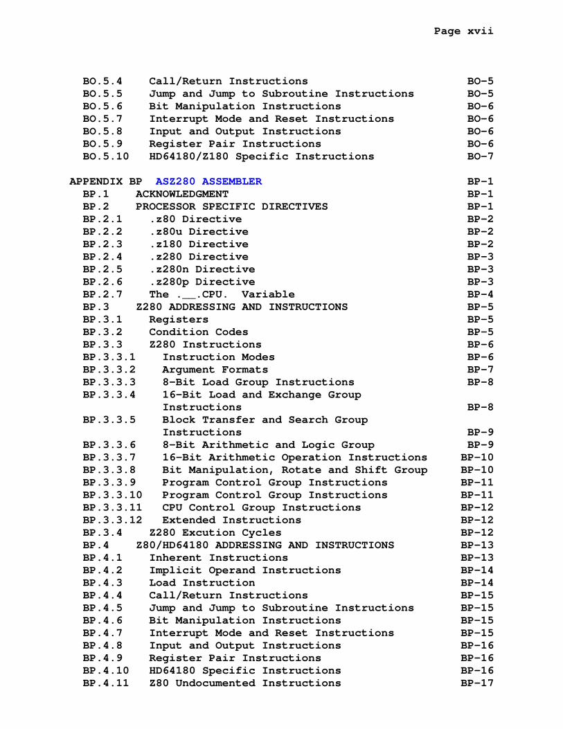
BO.5.4 Call/Return Instructions BO-5 BO.5.5 Jump and Jump to Subroutine Instructions BO-5 BO.5.6 Bit Manipulation Instructions BO-6 BO.5.7 Interrupt Mode and Reset Instructions BO-6 BO.5.8 Input and Output Instructions BO-6 BO.5.9 Register Pair Instructions BO-6 BO.5.10 HD64180/Z180 Specific Instructions BO-7
APPENDIX BP ASZ280 ASSEMBLER BP-1 BP.1 ACKNOWLEDGMENT BP-1 BP.2 PROCESSOR SPECIFIC DIRECTIVES BP-1 BP.2.1 .z80 Directive BP-2 BP.2.2 .z80u Directive BP-2 BP.2.3 .z180 Directive BP-2 BP.2.4 .z280 Directive BP-3 BP.2.5 .z280n Directive BP-3 BP.2.6 .z280p Directive BP-3 BP.2.7 The .__.CPU. Variable BP-4 BP.3 Z280 ADDRESSING AND INSTRUCTIONS BP-5 BP.3.1 Registers BP-5 BP.3.2 Condition Codes BP-5 BP.3.3 Z280 Instructions BP-6 BP.3.3.1 Instruction Modes BP-6 BP.3.3.2 Argument Formats BP-7 BP.3.3.3 8-Bit Load Group Instructions BP-8 BP.3.3.4 16-Bit Load and Exchange Group Instructions BP-8 BP.3.3.5 Block Transfer and Search Group Instructions BP-9 BP.3.3.6 8-Bit Arithmetic and Logic Group BP-9 BP.3.3.7 16-Bit Arithmetic Operation Instructions BP-10 BP.3.3.8 Bit Manipulation, Rotate and Shift Group BP-10 BP.3.3.9 Program Control Group Instructions BP-11 BP.3.3.10 Program Control Group Instructions BP-11 BP.3.3.11 CPU Control Group Instructions BP-12 BP.3.3.12 Extended Instructions BP-12 BP.3.4 Z280 Excution Cycles BP-12 BP.4 Z80/HD64180 ADDRESSING AND INSTRUCTIONS BP-13 BP.4.1 Inherent Instructions BP-13 BP.4.2 Implicit Operand Instructions BP-14 BP.4.3 Load Instruction BP-14 BP.4.4 Call/Return Instructions BP-15 BP.4.5 Jump and Jump to Subroutine Instructions BP-15 BP.4.6 Bit Manipulation Instructions BP-15 BP.4.7 Interrupt Mode and Reset Instructions BP-15 BP.4.8 Input and Output Instructions BP-16 BP.4.9 Register Pair Instructions BP-16 BP.4.10 HD64180 Specific Instructions BP-16 BP.4.11 Z80 Undocumented Instructions BP-17
Page 2
P R E F A C E
The ASxxxx assemblers were written following the style of several unfinished cross assemblers found in the Digital Equip- ment Corporation Users Society (DECUS) distribution of the C programming language. The incomplete DECUS code was provided with no documentation as to the input syntax or the output format. I wish to thank the author for inspiring me to begin the development of this set of assemblers.
The ASLINK program was written as a companion to the ASxxxx assemblers, its design and implementation was not derived from any other work.
I would greatly appreciate receiving the details of any changes, additions, or errors pertaining to these programs and will attempt to incorporate any fixes or generally useful changes in a future update to these programs.
Alan R. Baldwin Kent State University Physics Department Kent, Ohio 44242 U.S.A.
http://shop-pdp.net
[email protected] tel: (330) 672 2531 fax: (330) 672 2959
Page 3
E N D U S E R L I C E N S E A G R E E M E N T
Copyright (C) 1989-2019 Alan R. Baldwin
This program is free software: you can redistribute it and/or modify it under the terms of the GNU General Public License as published by the Free Software Foundation, either version 3 of the License, or (at your option) any later version.
This program is distributed in the hope that it will be use- ful, but WITHOUT ANY WARRANTY; without even the implied war- ranty of MERCHANTABILITY or FITNESS FOR A PARTICULAR PURPOSE. See the GNU General Public License for more details.
You should have received a copy of the GNU General Public License along with this program. If not, see <http://www.gnu.org/licenses/>.

Page 4
ASxxxx Cross Assemblers, Version 5.30, January 2019
Submitted by Alan R. Baldwin, Kent State University, Kent, Ohio
Operating System: Linux, Windows, MS-DOS or other supporting ANSI C.
Source Langauge: C
Abstract:
The ASxxxx assemblers are a series of microprocessor assem- blers written in the C programming language. This collection contains cross assemblers for the 1802, S2650, SC/MP, MPS430, 6100, 61860, 6500, 6800(6802/6808), 6801(6803/HD6303), 6804, 6805, 68HC(S)08, 6809, 68HC11, 68HC(S)12, 68HC16, 740, 78K/0, 78K/0S, 8008, 8008S, 8048(8041/8022/8021) 8051, 8085(8080), 8X300(8X305), DS8XCXXX, AVR, EZ80, F2MC8L/FX, F8/3870, GameBoy(Z80), H8/3xx, Cypress PSoC(M8C), PIC, Rabbit 2000/3000, ST6, ST7, ST8, Z8, Z80(HD64180), and Z280 series microproces- sors. Each assembler has a device specific section which includes: (1) device description, byte order, and file exten- sion information, (2) a table of assembler general directives, special directives, assembler mnemonics and associated operation codes, (3) machine specific code for processing the device mnemonics, addressing modes, and special directives.
The assemblers have a common device independent section which handles the details of file input/output, symbol table genera- tion, program/data areas, expression analysis, and assembler directive processing.
The assemblers provide the following features: (1) alpha- betized, formatted symbol table listings, (2) relocatable object modules, (3) global symbols for linking object modules, (4) con- ditional assembly directives, (5) reusable local symbols, (6) include-file processing, and (7) a general macro processing facility.
The companion program ASLINK is a relocating linker perform- ing the following functions: (1) bind multiple object modules into a single memory image, (2) resolve inter-module symbol references, (3) resolve undefined symbols from specified librarys of object modules, (4) process absolute, relative, con- catenated, and overlay attributes in data and program sections, (5) perform byte and word program-counter relative (pc or pcr) addressing calculations, (6) define absolute symbol values at link time, (7) define absolute area base address values at link

Page 5
time, (8) produce an Intel Hex record, Motorola S record or Tandy CoCo Disk Basic output file, (9) produce a map of the linked memory image, and (10) update the ASxxxx assembler list- ing files with the absolute linked addresses and data.
The assemblers and linker have been tested using Linux and DJGPP, Cygwin, Symantec C/C++ V7.2, Borland Turbo C++ 3.0, Open Watcom V1.9, VC6, Visual Studio 2005, 2010, 2013, and 2015. Complete source code and documentation for the assemblers and linker is included with the distribution. Additionally, test code for each assembler and several microprocessor monitors ( ASSIST05 for the 6805, MONDEB and ASSIST09 for the 6809, and BUFFALO 2.5 for the 6811) are included as working examples of use of these assemblers.
CHAPTER 1
THE ASSEMBLER
1.1 THE ASXXXX ASSEMBLERS
The ASxxxx assemblers are a series of microprocessor assem- blers written in the C programming language. Each assembler has a device specific section which includes:
1. device description, byte order, and file extension in- formation
2. a table of the assembler general directives, special device directives, assembler mnemonics and associated operation codes
3. machine specific code for processing the device mnemon- ics, addressing modes, and special directives
The device specific information is detailed in the appendices.
The assemblers have a common device independent section which handles the details of file input/output, symbol table genera- tion, program/data areas, expression analysis, and assembler directive processing.
The assemblers provide the following features:
1. Command string control of assembly functions
2. Alphabetized, formatted symbol table listing
3. Relocatable object modules
THE ASSEMBLER PAGE 1-2 THE ASXXXX ASSEMBLERS
4. Global symbols for linking object modules
5. Conditional assembly directives
6. Program sectioning directives
ASxxxx assembles one or more source files into a single relo- catable ascii object file. The output of the ASxxxx assemblers consists of an ascii relocatable object file(*.rel), an assembly listing file(*.lst), and a symbol file(*.sym) each controlled by an assembler option. If both the object and listing files are specified then a listing to relocated listing hint file (*.hlr) is created as a helper for the linker to properly create the relocated listing file.
1.1.1 Assembly Pass 1
During pass 1, ASxxxx opens all source files and performs a rudimentary assembly of each source statement. During this pro- cess all symbol tables are built, program sections defined, and number of bytes for each assembled source line is estimated.
At the end of pass 1 all undefined symbols may be made global (external) using the ASxxxx switch -g, otherwise undefined sym- bols will be flagged as errors during succeeding passes.
1.1.2 Assembly Pass 2
During pass 2 the ASxxxx assembler resolves forward refer- ences and determines the number of bytes for each assembled line. The number of bytes used by a particular assembler in- struction may depend upon the addressing mode, whether the in- struction allows multiple forms based upon the relative distance to the addressed location, or other factors. Pass 2 resolves these cases and determines the address of all symbols.
THE ASSEMBLER PAGE 1-3 THE ASXXXX ASSEMBLERS
1.1.3 Assembly Pass 3
Pass 3 by the assembler generates the listing file, the relo- catable output file, the listing to relocated listing hint file, and the symbol tables. Also during pass 3 the errors will be reported.
The relocatable object file is an ascii file containing sym- bol references and definitions, program area definitions, and the relocatable assembled code, the linker ASLINK will use this information to generate an absolute load file (Intel, Motorola or Tandy CoCo Disk Basic formats).
1.2 SOURCE PROGRAM FORMAT
1.2.1 Statement Format
A source program is composed of assembly-language statements. Each statement must be completed on one line. A line may con- tain a maximum of 128 characters, longer lines are truncated and lost.
An ASxxxx assembler statement may have as many as four fields. These fields are identified by their order within the statement and/or by separating characters between fields. The general format of the ASxxxx statement is:
[label:] Operator Operand [;Comment(s)]
The label and comment fields are optional. The operator and operand fields are interdependent. The operator field may be an assembler directive or an assembly mnemonic. The operand field may be optional or required as defined in the context of the operator.
ASxxxx interprets and processes source statements one at a time. Each statement causes a particular operation to be per- formed.
THE ASSEMBLER PAGE 1-4 SOURCE PROGRAM FORMAT
1.2.1.1 Label Field -
A label is a user-defined symbol which is assigned the value of the current location counter and entered into the user de- fined symbol table. The current location counter is used by ASxxxx to assign memory addresses to the source program state- ments as they are encountered during the assembly process. Thus a label is a means of symbolically referring to a specific statement.
When a program section is absolute, the value of the current location counter is absolute; its value references an absolute memory address. Similarly, when a program section is relocat- able, the value of the current location counter is relocatable. A relocation bias calculated at link time is added to the ap- parent value of the current location counter to establish its effective absolute address at execution time. (The user can also force the linker to relocate sections defined as absolute. This may be required under special circumstances.)
If present, a label must be the first field in a source statement and must be terminated by a colon (:). For example, if the value of the current location counter is absolute 01F0(H), the statement:
abcd: nop
assigns the value 01F0(H) to the label abcd. If the location counter value were relocatable, the final value of abcd would be 01F0(H)+K, where K represents the relocation bias of the program section, as calculated by the linker at link time.
More than one label may appear within a single label field. Each label so specified is assigned the same address value. For example, if the value of the current location counter is 1FF0(H), the multiple labels in the following statement are each assigned the value 1FF0(H):
abcd: aq: $abc: nop
Multiple labels may also appear on successive lines. For ex- ample, the statements
abcd: aq: $abc: nop
likewise cause the same value to be assigned to all three la- bels.
THE ASSEMBLER PAGE 1-5 SOURCE PROGRAM FORMAT
A double colon (::) defines the label as a global symbol. For example, the statement
abcd:: nop
establishes the label abcd as a global symbol. The distinguish- ing attribute of a global symbol is that it can be referenced from within an object module other than the module in which the symbol is defined. References to this label in other modules are resolved when the modules are linked as a composite execut- able image.
The legal characters for defining labels are:
A through Z a through z 0 through 9 . (Period) $ (Dollar sign) _ (underscore)
A label may be any length, however only the first 79 characters are significant and, therefore must be unique among all labels in the source program (not necessarily among separa- tely compiled modules). An error code(s) (<m> or <p>) will be generated in the assembly listing if the first 79 characters in two or more labels are the same. The <m> code is caused by the redeclaration of the symbol or its reference by another state- ment. The <p> code is generated because the symbols location is changing on each pass through the source file.
The label must not start with the characters 0-9, as this designates a reusable symbol with special attributes described in a later section.
The label must not start with the sequence $$, as this represents the temporary radix 16 for constants.

THE ASSEMBLER PAGE 1-6 SOURCE PROGRAM FORMAT
1.2.1.2 Operator Field -
The operator field specifies the action to be performed. It may consist of an instruction mnemonic (op code) or an assembler directive.
When the operator is an instruction mnemonic, a machine in- struction is generated and the assembler evaluates the addresses of the operands which follow. When the operator is a directive ASxxxx performs certain control actions or processing operations during assembly of the source program.
Leading and trailing spaces or tabs in the operator field have no significance; such characters serve only to separate the operator field from the preceeding and following fields.
An operator is terminated by a space, tab or end of line.
1.2.1.3 Operand Field -
When the operator is an instruction mnemonic (op code), the operand field contains program variables that are to be evaluated/manipulated by the operator.
Operands may be expressions or symbols, depending on the operator. Multiple expressions used in the operand fields may be separated by a comma. An operand should be preceeded by an operator field; if it is not, the statement will give an error (<q> or <o>). All operands following instruction mnemonics are treated as expressions.
The operand field is terminated by a semicolon when the field is followed by a comment. For example, in the following statement:
label: lda abcd,x ;Comment field
the tab between lda and abcd terminates the operator field and defines the beginning of the operand field; a comma separates the operands abcd and x; and a semicolon terminates the operand field and defines the beginning of the comment field. When no comment field follows, the operand field is terminated by the end of the source line.
THE ASSEMBLER PAGE 1-7 SOURCE PROGRAM FORMAT
1.2.1.4 Comment Field -
The comment field begins with a semicolon and extends through the end of the line. This field is optional and may contain any 7-bit ascii character except null.
Comments do not affect assembly processing or program execu- tion.
1.3 SYMBOLS AND EXPRESSIONS
This section describes the generic components of the ASxxxx assemblers: the character set, the conventions observed in con- structing symbols, and the use of numbers, operators, and ex- pressions.
1.3.1 Character Set
The following characters are legal in ASxxxx source programs:
1. The letters A through Z. Both upper- and lower-case letters are acceptable. The assemblers, by default, are case sensitive, i.e. ABCD and abcd are not the same symbols. (The assemblers can be made case insen- sitive by using the -z command line option.)
2. The digits 0 through 9
3. The characters . (period), $ (dollar sign), and _ (un- derscore).
4. The special characters listed in Tables 1 through 6.
Tables 1 through 6 describe the various ASxxxx label and field terminators, assignment operators, operand separators, as- sembly, unary, binary, and radix operators.
THE ASSEMBLER PAGE 1-8 SYMBOLS AND EXPRESSIONS
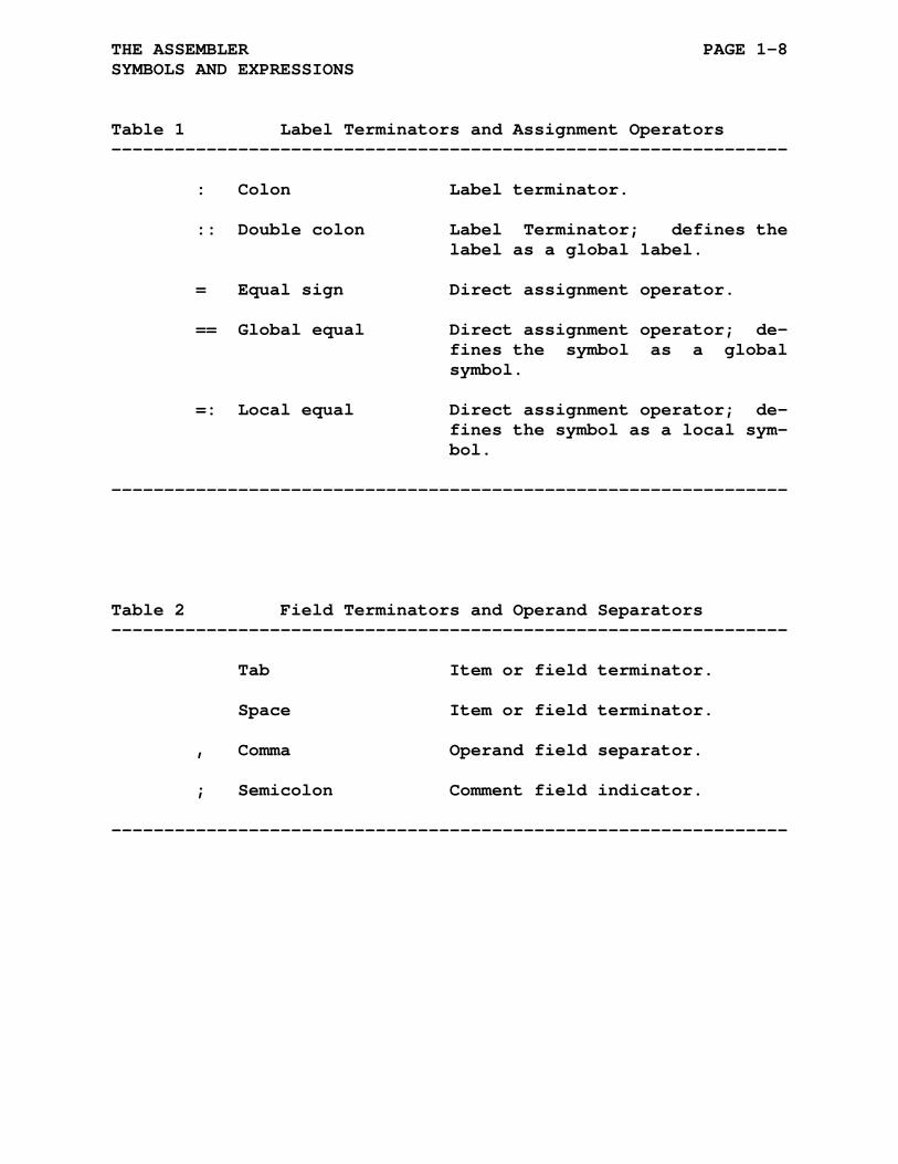
Table 1 Label Terminators and Assignment Operators ----------------------------------------------------------------
: Colon Label terminator.
:: Double colon Label Terminator; defines the label as a global label.
= Equal sign Direct assignment operator.
== Global equal Direct assignment operator; de- fines the symbol as a global symbol.
=: Local equal Direct assignment operator; de- fines the symbol as a local sym- bol.
----------------------------------------------------------------
Table 2 Field Terminators and Operand Separators ----------------------------------------------------------------
Tab Item or field terminator.
Space Item or field terminator.
, Comma Operand field separator.
; Semicolon Comment field indicator.
----------------------------------------------------------------
THE ASSEMBLER PAGE 1-9 SYMBOLS AND EXPRESSIONS
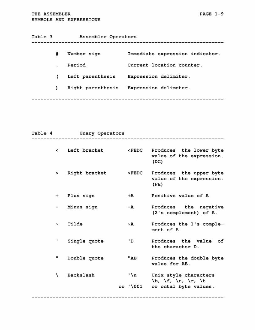
Table 3 Assembler Operators ----------------------------------------------------------------
# Number sign Immediate expression indicator.
. Period Current location counter.
( Left parenthesis Expression delimiter.
) Right parenthesis Expression delimeter.
----------------------------------------------------------------
Table 4 Unary Operators ----------------------------------------------------------------
< Left bracket <FEDC Produces the lower byte value of the expression. (DC)
> Right bracket >FEDC Produces the upper byte value of the expression. (FE)
+ Plus sign +A Positive value of A
- Minus sign -A Produces the negative (2's complement) of A.
~ Tilde ~A Produces the 1's comple- ment of A.
' Single quote 'D Produces the value of the character D.
" Double quote "AB Produces the double byte value for AB.
\ Backslash '\n Unix style characters \b, \f, \n, \r, \t or '\001 or octal byte values.
----------------------------------------------------------------
THE ASSEMBLER PAGE 1-10 SYMBOLS AND EXPRESSIONS
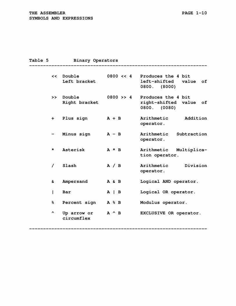
Table 5 Binary Operators ----------------------------------------------------------------
<< Double 0800 << 4 Produces the 4 bit Left bracket left-shifted value of 0800. (8000)
>> Double 0800 >> 4 Produces the 4 bit Right bracket right-shifted value of 0800. (0080)
+ Plus sign A + B Arithmetic Addition operator.
- Minus sign A - B Arithmetic Subtraction operator.
* Asterisk A * B Arithmetic Multiplica- tion operator.
/ Slash A / B Arithmetic Division operator.
& Ampersand A & B Logical AND operator.
| Bar A | B Logical OR operator.
% Percent sign A % B Modulus operator.
^ Up arrow or A ^ B EXCLUSIVE OR operator. circumflex
----------------------------------------------------------------

THE ASSEMBLER PAGE 1-11 SYMBOLS AND EXPRESSIONS
Table 6 Temporary Radix Operators ----------------------------------------------------------------
$%, 0b, 0B Binary radix operator.
$&, 0o, 0O, 0q, 0Q Octal radix operator.
$#, 0d, 0D Decimal radix operator.
$$, 0h, 0H, 0x, 0X Hexidecimal radix operator.
Potential ambiguities arising from the use of 0b and 0d as temporary radix operators may be circumvented by pre- ceding all non-prefixed hexidecimal numbers with 00. Leading 0's are required in any case where the first hexidecimal digit is abcdef as the assembler will treat the letter sequence as a label.
----------------------------------------------------------------
1.3.2 User-Defined Symbols
User-defined symbols are those symbols that are equated to a specific value through a direct assignment statement or appear as labels. These symbols are added to the User Symbol Table as they are encountered during assembly.
The following rules govern the creation of user-defined symbols:
1. Symbols can be composed of alphanumeric characters, dollar signs ($), periods (.), and underscores (_) only.
2. The first character of a symbol must not be a number (except in the case of reusable symbols).
3. The first 79 characters of a symbol must be unique. A symbol can be written with more than 79 legal characters, but the 80th and subsequent characters are ignored.

THE ASSEMBLER PAGE 1-12 SYMBOLS AND EXPRESSIONS
4. Spaces and Tabs must not be embedded within a symbol.
1.3.3 Reusable Symbols
Reusable symbols are specially formatted symbols used as la- bels within a block of coding that has been delimited as a reus- able symbol block. Reusable symbols are of the form n$, where n is a decimal integer from 0 to 65535, inclusive. Examples of reusable symbols are:
1$ 27$ 138$ 244$
The range of a reusable symbol block consists of those state- ments between two normally constructed symbolic labels. Note that a statement of the form:
ALPHA = EXPRESSION
is a direct assignment statement but does not create a label and thus does not delimit the range of a reusable symbol block.
Note that the range of a reusable symbol block may extend across program areas.
Reusable symbols provide a convenient means of generating la- bels for branch instructions and other such references within reusable symbol blocks. Using reusable symbols reduces the pos- sibility of symbols with multiple definitions appearing within a user program. In addition, the use of reusable symbols dif- ferentiates entry-point labels from other labels, since reusable labels cannot be referenced from outside their respective symbol blocks. Thus, reusable symbols of the same name can appear in other symbol blocks without conflict. Reusable symbols require less symbol table space than normal symbols. Their use is recommended.
The use of the same reusable symbol within a symbol block will generate one or both of the <m> or <p> errors.

THE ASSEMBLER PAGE 1-13 SYMBOLS AND EXPRESSIONS
Example of reusable symbols:
a: ldx #atable ;get table address lda #0d48 ;table length 1$: clr ,x+ ;clear deca bne 1$ b: ldx #btable ;get table address lda #0d48 ;table length 1$: clr ,x+ ;clear deca bne 1$
1.3.4 Current Location Counter
The period (.) is the symbol for the current location coun- ter. When used in the operand field of an instruction, the period represents the address of the first byte of the instruction:
AS: ldx #. ;The period (.) refers to ;the address of the ldx ;instruction.
When used in the operand field of an ASxxxx directive, it represents the address of the current byte or word:
QK = 0 .word 0xFFFE,.+4,QK ;The operand .+4 in the .word ;directive represents a value ;stored in the second of the ;three words during assembly.
If we assume the current value of the program counter is 0H0200, then during assembly, ASxxxx reserves three words of storage starting at location 0H0200. The first value, a hex- idecimal constant FFFE, will be stored at location 0H0200. The second value represented by .+4 will be stored at location 0H0202, its value will be 0H0206 ( = 0H0202 + 4). The third value defined by the symbol QK will be placed at location 0H0204.
At the beginning of each assembly pass, ASxxxx resets the lo- cation counter. Normally, consecutive memory locations are assigned to each byte of object code generated. However, the
THE ASSEMBLER PAGE 1-14 SYMBOLS AND EXPRESSIONS
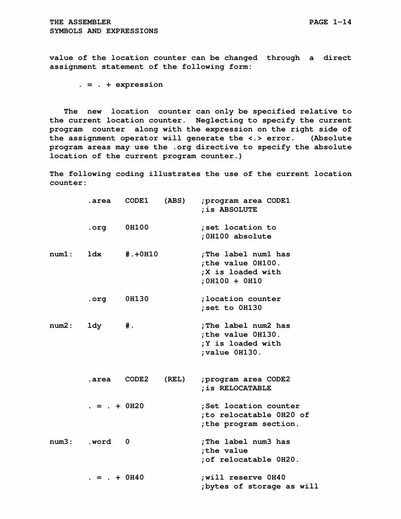
value of the location counter can be changed through a direct assignment statement of the following form:
. = . + expression
The new location counter can only be specified relative to the current location counter. Neglecting to specify the current program counter along with the expression on the right side of the assignment operator will generate the <.> error. (Absolute program areas may use the .org directive to specify the absolute location of the current program counter.)
The following coding illustrates the use of the current location counter:
.area CODE1 (ABS) ;program area CODE1 ;is ABSOLUTE .org 0H100 ;set location to ;0H100 absolute num1: ldx #.+0H10 ;The label num1 has ;the value 0H100. ;X is loaded with ;0H100 + 0H10 .org 0H130 ;location counter ;set to 0H130 num2: ldy #. ;The label num2 has ;the value 0H130. ;Y is loaded with ;value 0H130. .area CODE2 (REL) ;program area CODE2 ;is RELOCATABLE . = . + 0H20 ;Set location counter ;to relocatable 0H20 of ;the program section. num3: .word 0 ;The label num3 has ;the value ;of relocatable 0H20. . = . + 0H40 ;will reserve 0H40 ;bytes of storage as will
THE ASSEMBLER PAGE 1-15 SYMBOLS AND EXPRESSIONS
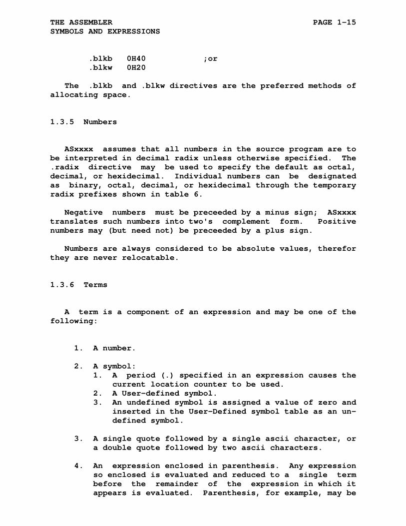
.blkb 0H40 ;or .blkw 0H20
The .blkb and .blkw directives are the preferred methods of allocating space.
1.3.5 Numbers
ASxxxx assumes that all numbers in the source program are to be interpreted in decimal radix unless otherwise specified. The .radix directive may be used to specify the default as octal, decimal, or hexidecimal. Individual numbers can be designated as binary, octal, decimal, or hexidecimal through the temporary radix prefixes shown in table 6.
Negative numbers must be preceeded by a minus sign; ASxxxx translates such numbers into two's complement form. Positive numbers may (but need not) be preceeded by a plus sign.
Numbers are always considered to be absolute values, therefor they are never relocatable.
1.3.6 Terms
A term is a component of an expression and may be one of the following:
1. A number.
2. A symbol: 1. A period (.) specified in an expression causes the current location counter to be used. 2. A User-defined symbol. 3. An undefined symbol is assigned a value of zero and inserted in the User-Defined symbol table as an un- defined symbol.
3. A single quote followed by a single ascii character, or a double quote followed by two ascii characters.
4. An expression enclosed in parenthesis. Any expression so enclosed is evaluated and reduced to a single term before the remainder of the expression in which it appears is evaluated. Parenthesis, for example, may be
THE ASSEMBLER PAGE 1-16 SYMBOLS AND EXPRESSIONS
used to alter the left-to-right evaluation of expres- sions, (as in A*B+C versus A*(B+C)), or to apply a un- ary operator to an entire expression (as in -(A+B)).
5. A unary operator followed by a symbol or number.
1.3.7 Expressions
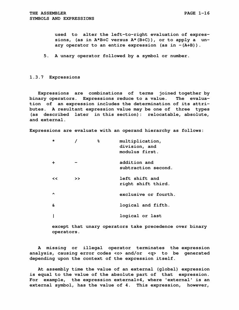
Expressions are combinations of terms joined together by binary operators. Expressions reduce to a value. The evalua- tion of an expression includes the determination of its attri- butes. A resultant expression value may be one of three types (as described later in this section): relocatable, absolute, and external.
Expressions are evaluate with an operand hierarchy as follows:
* / % multiplication, division, and modulus first. + - addition and subtraction second. << >> left shift and right shift third. ^ exclusive or fourth. & logical and fifth. | logical or last except that unary operators take precedence over binary operators.
A missing or illegal operator terminates the expression analysis, causing error codes <o> and/or <q> to be generated depending upon the context of the expression itself.
At assembly time the value of an external (global) expression is equal to the value of the absolute part of that expression. For example, the expression external+4, where 'external' is an external symbol, has the value of 4. This expression, however,
THE ASSEMBLER PAGE 1-17 SYMBOLS AND EXPRESSIONS
when evaluated at link time takes on the resolved value of the symbol 'external', plus 4.
Expressions, when evaluated by ASxxxx, are one of three types: relocatable, absolute, or external. The following dis- tinctions are important:
1. An expression is relocatable if its value is fixed re- lative to the base address of the program area in which it appears; it will have an offset value added at link time. Terms that contain labels defined in relocatable program areas will have a relocatable value; simi- larly, a period (.) in a relocatable program area, representing the value of the current program location counter, will also have a relocatable value.
2. An expression is absolute if its value is fixed. An expression whose terms are numbers and ascii characters will reduce to an absolute value. A relocatable ex- pression or term minus a relocatable term, where both elements being evaluated belong to the same program area, is an absolute expression. This is because every term in a program area has the same relocation bias. When one term is subtracted from the other the reloca- tion bias is zero.
3. An expression is external (or global) if it contains a single global reference (plus or minus an absolute ex- pression value) that is not defined within the current program. Thus, an external expression is only par- tially defined following assembly and must be resolved at link time.
1.4 GENERAL ASSEMBLER DIRECTIVES
An ASxxxx directive is placed in the operator field of the source line. Only one directive is allowed per source line. Each directive may have a blank operand field or one or more operands. Legal operands differ with each directive.
THE ASSEMBLER PAGE 1-18 GENERAL ASSEMBLER DIRECTIVES
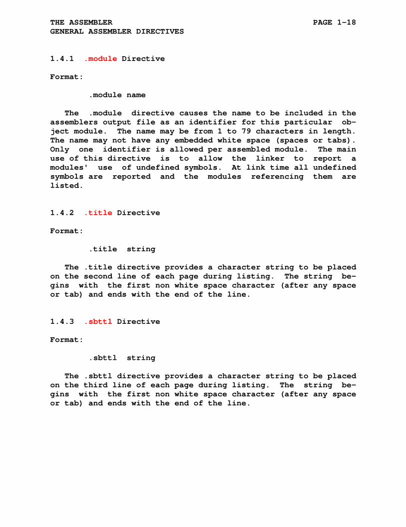
1.4.1 .module Directive
Format:
.module name
The .module directive causes the name to be included in the assemblers output file as an identifier for this particular ob- ject module. The name may be from 1 to 79 characters in length. The name may not have any embedded white space (spaces or tabs). Only one identifier is allowed per assembled module. The main use of this directive is to allow the linker to report a modules' use of undefined symbols. At link time all undefined symbols are reported and the modules referencing them are listed.
1.4.2 .title Directive
Format:
.title string
The .title directive provides a character string to be placed on the second line of each page during listing. The string be- gins with the first non white space character (after any space or tab) and ends with the end of the line.
1.4.3 .sbttl Directive
Format:
.sbttl string
The .sbttl directive provides a character string to be placed on the third line of each page during listing. The string be- gins with the first non white space character (after any space or tab) and ends with the end of the line.
THE ASSEMBLER PAGE 1-19 GENERAL ASSEMBLER DIRECTIVES
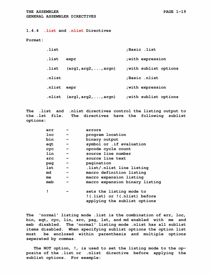
1.4.4 .list and .nlist Directives
Format:
.list ;Basic .list
.list expr ;with expression
.list (arg1,arg2,...,argn) ;with sublist options
.nlist ;Basic .nlist
.nlist expr ;with expression
.nlist (arg1,arg2,...,argn) ;with sublist options
The .list and .nlist directives control the listing output to the .lst file. The directives have the following sublist options:
err - errors loc - program location bin - binary output eqt - symbol or .if evaluation cyc - opcode cycle count lin - source line number src - source line text pag - pagination lst - .list/.nlist line listing md - macro definition listing me - macro expansion listing meb - macro expansion binary listing ! - sets the listing mode to !(.list) or !(.nlist) before applying the sublist options
The 'normal' listing mode .list is the combination of err, loc, bin, eqt, cyc, lin, src, pag, lst, and md enabled with me and meb disabled. The 'normal' listing mode .nlist has all sublist items disabled. When specifying sublist options the option list must be enclosed within parenthesis and multiple options seperated by commas.
The NOT option, !, is used to set the listing mode to the op- posite of the .list or .nlist directive before applying the sublist options. For example:

THE ASSEMBLER PAGE 1-20 GENERAL ASSEMBLER DIRECTIVES
.nlist (!) is equivalent to .list and .list (!) is equivalent to .nlist any additional options will be applied normally
Normal .list/.nlist processing is disabled within false con- ditional blocks. However, the .list/.nlist with an expression can override this behavior if the expression has a non zero value.
Examples of listing options:
.list (meb) ; macro processing lists only ; generated binary and location .list (me) ; listing options are enabled ; during macro processing .nlist (src) ; .nlist src lines not listed .nlist (!,lst) ; list all except .nlist .nlist ; combination lists only .list (src) ; the source line .list (!,src) ; list only the source line .list 1 ; enable listing even within ; a FALSE conditional block
1.4.5 .page Directive
Format:
.page
The .page directive causes a page ejection with a new heading to be printed. The new page occurs after the next line of the source program is processed, this allows an immediately follow- ing .sbttl directive to appear on the new page. The .page source line will not appear in the file listing. Paging may be disabled by invoking the -p directive or by using the directive:
.nlist (pag)
THE ASSEMBLER PAGE 1-21 GENERAL ASSEMBLER DIRECTIVES
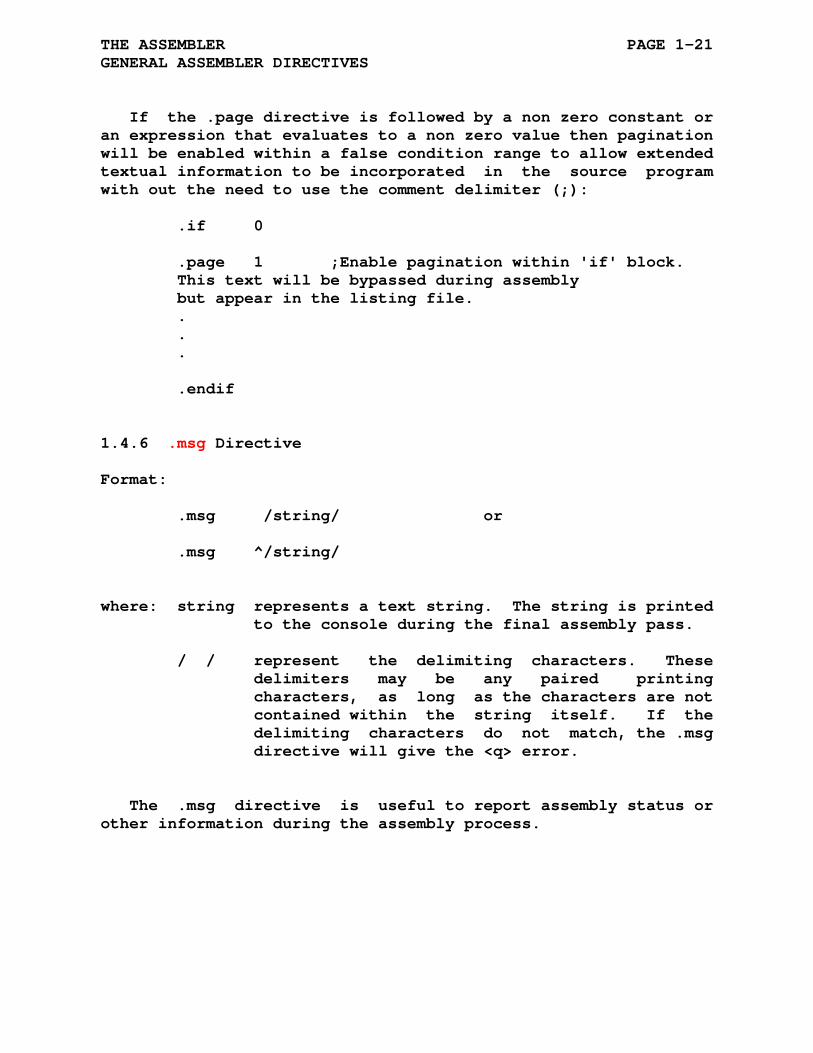
If the .page directive is followed by a non zero constant or an expression that evaluates to a non zero value then pagination will be enabled within a false condition range to allow extended textual information to be incorporated in the source program with out the need to use the comment delimiter (;):
.if 0 .page 1 ;Enable pagination within 'if' block. This text will be bypassed during assembly but appear in the listing file. . . . .endif
1.4.6 .msg Directive
Format:
.msg /string/ or
.msg ^/string/
where: string represents a text string. The string is printed to the console during the final assembly pass.
/ / represent the delimiting characters. These delimiters may be any paired printing characters, as long as the characters are not contained within the string itself. If the delimiting characters do not match, the .msg directive will give the <q> error.
The .msg directive is useful to report assembly status or other information during the assembly process.
THE ASSEMBLER PAGE 1-22 GENERAL ASSEMBLER DIRECTIVES
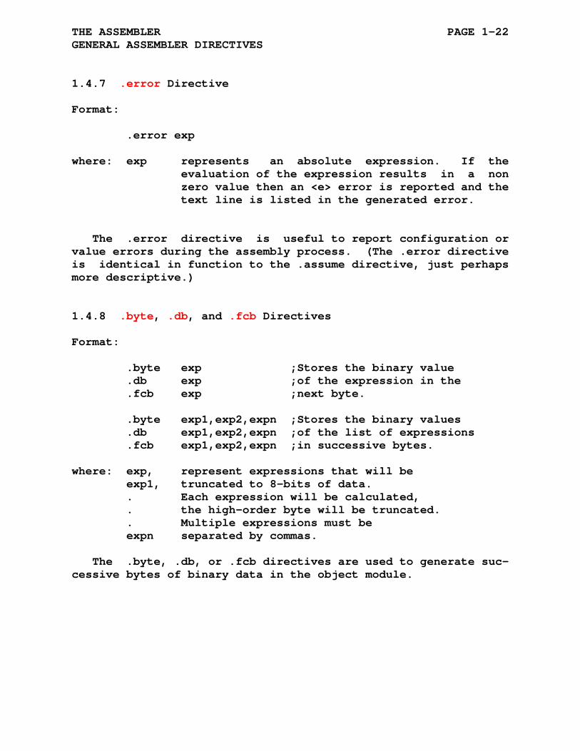
1.4.7 .error Directive
Format:
.error exp
where: exp represents an absolute expression. If the evaluation of the expression results in a non zero value then an <e> error is reported and the text line is listed in the generated error.
The .error directive is useful to report configuration or value errors during the assembly process. (The .error directive is identical in function to the .assume directive, just perhaps more descriptive.)
1.4.8 .byte, .db, and .fcb Directives
Format:
.byte exp ;Stores the binary value .db exp ;of the expression in the .fcb exp ;next byte. .byte exp1,exp2,expn ;Stores the binary values .db exp1,exp2,expn ;of the list of expressions .fcb exp1,exp2,expn ;in successive bytes. where: exp, represent expressions that will be exp1, truncated to 8-bits of data. . Each expression will be calculated, . the high-order byte will be truncated. . Multiple expressions must be expn separated by commas.
The .byte, .db, or .fcb directives are used to generate suc- cessive bytes of binary data in the object module.

THE ASSEMBLER PAGE 1-23 GENERAL ASSEMBLER DIRECTIVES
1.4.9 .word, .dw, and .fdb Directives
Format:
.word exp ;Stores the binary value .dw exp ;of the expression in .fdb exp ;the next word. .word exp1,exp2,expn ;Stores the binary values .dw exp1,exp2,expn ;of the list of expressions .fdb exp1,exp2,expn ;in successive words. where: exp, represent expressions that will occupy two exp1, bytes of data. Each expression will be . calculated as a 16-bit word expression. . Multiple expressions must be expn separated by commas.
The .word, .dw, or .fdb directives are used to generate suc- cessive words of binary data in the object module.
1.4.10 .3byte and .triple Directives
Format:
.3byte exp ;Stores the binary value .triple exp ;of the expression in ;the next triple (3 bytes). .3byte exp1,exp2,expn ;Stores the binary values .triple exp1,exp2,expn ;of the list of expressions ;in successive triples ;(3 bytes). where: exp, represent expressions that will occupy three exp1, bytes of data. Each expression will be . calculated as a 24-bit word expression. . Multiple expressions must be expn separated by commas.
The .3byte or .triple directive is used to generate succes- sive triples of binary data in the object module. (These direc- tives are only available in assemblers supporting 24-bit addressing.)

THE ASSEMBLER PAGE 1-24 GENERAL ASSEMBLER DIRECTIVES
1.4.11 .4byte and .quad Directive
Format:
.4byte exp ;Stores the binary value .quad exp ;of the expression in ;the next quad (4 bytes). .4byte exp1,exp2,expn ;Stores the binary values .quad exp1,exp2,expn ;of the list of expressions ;in successive quads ;(4 bytes). where: exp, represent expressions that will occupy three exp1, bytes of data. Each expression will be . calculated as a 32-bit word expression. . Multiple expressions must be expn separated by commas.
The .4byte or .quad directive is used to generate successive quads of binary data in the object module. (These directives are only available in assemblers supporting 32-bit addressing.)
1.4.12 .blkb, .ds, .rmb, and .rs Directives
Format:
.blkb N ;reserve N bytes of space .ds N ;reserve N bytes of space .rmb N ;reserve N bytes of space .rs N ;reserve N bytes of space
The .blkb, .ds, .rmb, and .rs directives reserve byte blocks in the object module;
1.4.13 .blkw, .blk3, and .blk4 Directives
Format:
.blkw N ;reserve N words of space .blk3 N ;reserve N triples of space .blk4 N ;reserve N quads of space
The .blkw directive reserves word blocks; the .blk3 reserves 3 byte blocks(available in assemblers supporting 24-bit addressing); the .blk4 reserves 4 byte blocks (available in assemblers supporting 32-bit addressing).

THE ASSEMBLER PAGE 1-25 GENERAL ASSEMBLER DIRECTIVES
1.4.14 .ascii, .str, and .fcc Directives
Format:
.ascii /string/ or
.ascii ^/string/
.fcc /string/ or
.fcc ^/string/
.str /string/ or
.str ^/string/
where: string is a string of printable ascii characters.
/ / represent the delimiting characters. These delimiters may be any paired printing characters, as long as the characters are not contained within the string itself. If the delimiting characters do not match, the .ascii directive will give the <q> error.
The .ascii, .fcc, and .str directives place one binary byte of data for each character in the string into the object module.
1.4.15 .ascis and .strs Directives
Format:
.ascis /string/ or
.ascis ^/string/
.strs /string/ or
.strs ^/string/
where: string is a string of printable ascii characters.
/ / represent the delimiting characters. These delimiters may be any paired printing characters, as long as the characters are not contained within the string itself. If the
THE ASSEMBLER PAGE 1-26 GENERAL ASSEMBLER DIRECTIVES
delimiting characters do not match, the .ascis and .strs directives will give the <q> error.
The .ascis and .strs directives place one binary byte of data for each character in the string into the object module. The last character in the string will have the high order bit set.
1.4.16 .asciz and .strz Directives
Format:
.asciz /string/ or
.asciz ^/string/
.strz /string/ or
.strz ^/string/
where: string is a string of printable ascii characters.
/ / represent the delimiting characters. These delimiters may be any paired printing characters, as long as the characters are not contained within the string itself. If the delimiting characters do not match, the .asciz and .strz directive will give the <q> error.
The .asciz and .strz directives place one binary byte of data for each character in the string into the object module. Fol- lowing all the character data a zero byte is inserted to ter- minate the character string.

THE ASSEMBLER PAGE 1-27 GENERAL ASSEMBLER DIRECTIVES
1.4.17 .assume Directive
Format:
.assume exp
where: exp represents an absolute expression. If the evaluation of the expression results in a non zero value then an <e> error is reported and the text line is listed in the generated error.
The .assume directive is useful to check assumptions about assembler values. (The .assume directive is identical in func- tion to the .error directive, just perhaps more descriptive.)
1.4.18 .radix Directive
Format:
.radix character
where: character represents a single character specifying the default radix to be used for succeeding numbers. The character may be any one of the following:
B,b Binary O,o Octal Q,q D,d Decimal 'blank' H,h Hexidecimal X,x
THE ASSEMBLER PAGE 1-28 GENERAL ASSEMBLER DIRECTIVES
1.4.19 .even Directive
Format:
.even
The .even directive ensures that the current location counter contains an even boundary value by adding 1 if the current loca- tion is odd.
1.4.20 .odd Directive
Format:
.odd
The .odd directive ensures that the current location counter contains an odd boundary value by adding one if the current lo- cation is even.
1.4.21 .bndry Directive
Format:
.bndry n
If the current location is not an integer multiple of n then the location counter is increased to the next integer multiple of n.
As an example:
.bndry 4
changes the current location to be at a multiple of 4, a 4-byte boundary.
The boundary specifications are propagated to the linker as a boundary modulus, ie the smallest common boundary for all .odd, .even, and .bndry directives contained within the area. A boun- dary value of 1 is equivalent to .odd and a boundary value of 2 is equivalent to .even. Because areas are always assembled with an initial address of 0, an even address, both .odd and .even are modulus 2 boundaries.
As an example, suppose there are two sections: a CODE sec- tion and a DATA section. The program code is written so that

THE ASSEMBLER PAGE 1-29 GENERAL ASSEMBLER DIRECTIVES
the data associated with this section of the program code fol- lows immediately.
.area CODE ; Subroutine 1 Code ; Uses data having a boundary of 6 .area DATA ; Subroutine 1 Data .bndry 6 .word 1, 2, 3 ... .area CODE ; Subroutine 2 Code ; Uses data having a boundary of 8 .area DATA ; Subroutine 2 Data .bndry 8 .word 1, 2, 3, 4,
Since the CODE and DATA sections are assembled during a sin- gle assembly (also applies to include files) the the assembler compiles all CODE segments as a single area segment. The assem- bler also compiles all the DATA segments as a single area seg- ment which has two .bndry directives and will have a boundary modulus of 24. 24 is the smallest boundary divisible by 6 and 8 with no remainder. When the assembled file is linked the loca- tion of the data in the DATA area will be offset to an address which has a boundary modulus of 24.
When multiple files containing the same area names (projects with multiple independently compiled files or library files) are linked together each area segment will be offset to match the segments boundary modulus.
Boundary specifications will also be preserved when an area base address is specified with the -b linker option and/or the area is placed within a bank.
THE ASSEMBLER PAGE 1-30 GENERAL ASSEMBLER DIRECTIVES
1.4.22 .area Directive
Format:
.area name [(options)]
where: name represents the symbolic name of the program sec- tion. This name may be the same as any user-defined symbol or bank as the area names are independent of all symbols, labels, and banks.
options specify the type of program or data area: ABS absolute (automatically invokes OVR) REL relocatable OVR overlay CON concatenate NOPAG non-paged area PAG paged area
options specify a code or data segment: CSEG Code segment DSEG Data segment
option specifies the data area bank: BANK Named collection of areas
The .area directive provides a means of defining and separat- ing multiple programming and data sections. The name is the area label used by the assembler and the linker to collect code from various separately assembled modules into one section. The name may be from 1 to 79 characters in length.
The options are specified within parenthesis and separated by commas as shown in the following example:
.area TEST (REL,CON) ;This section is relocatable ;and concatenated with other ;sections of this program area. .area DATA (REL,OVR) ;This section is relocatable ;and overlays other sections ;of this program area. .area SYS (ABS,OVR) ;(CON not allowed with ABS) ;This section is defined as ;absolute. Absolute sections ;are always overlayed with

THE ASSEMBLER PAGE 1-31 GENERAL ASSEMBLER DIRECTIVES
;other sections of this program ;area. .area PAGE (PAG) ;This is a paged section. The ;section must be on a 256 byte ;boundary and its length is ;checked by the linker to be ;no larger than 256 bytes. ;This is useful for direct page ;areas.
The default area type is REL|CON; i.e. a relocatable sec- tion which is concatenated with other sections of code with the same area name. The ABS option indicates an absolute area. The OVR and CON options indicate if program sections of the same name will overlay each other (start at the same location) or be concatenated with each other (appended to each other).
The area can be specified as either a code segment, CSEG, or a data segment, DSEG. The CSEG and DSEG descriptors are useful when the microprocessor code and data unit allocations are unequal: e.g. the executable code uses an allocation of 2 bytes for each instruction and is addressed at an increment of 1 for every instruction, and the data uses an allocation of 1 byte for each element and is addressed at an increment of 1 for each data byte. The allocation units are defined by the architecture of the particular microprocessor.
The .area directive also provides a means of specifying the bank this area is associated with. All areas associated with a particular bank are combined at link time into a block of code/data.
The CSEG, DSEG, and BANK options are specified within the parenthesis as shown in the following examples:
.area C_SEG (CSEG,BANK=C1) ;This is a code section ;and is included in bank C1 .area D_SEG (DSEG,BANK=D1) ;This is a data section ;and is included in bank D1.
Multiple invocations of the .area directive with the same name must specify the same options or leave the options field blank, this defaults to the previously specified options for this program area.
THE ASSEMBLER PAGE 1-32 GENERAL ASSEMBLER DIRECTIVES
The ASxxxx assemblers automatically provide two program sections:
'_CODE' This is the default code/data area. This program area is of type (REL,CON,CSEG).
'_DATA' This is the default optional data area. This program area is of type (REL,CON,DSEG).
The .area names and options are never case sensitive.
1.4.23 .bank Directive
Format:
.bank name [(options)]
where: name represents the symbolic name of the bank sec- tion. This name may be the same as any user-defined symbol or area as the bank names are independent of all symbols, labels, and areas. The name may be from 1 to 79 characters in length.
options specify the parameters of the bank: BASE base address of bank SIZE maximum size of bank FSFX file suffix for this bank MAP NOICE mapping
The .bank directive allows an arbitrary grouping of program and/or data areas to be communicated to the linker. The bank parameters are all optional and are described as follows:
1. BASE, the starting address of the bank (default is 0) may be defined. This address can be overridden by us- ing the linker -b option for the first area within the bank. The bank address is always specified in 'byte' addressing. A first area which is not 'byte' addressed (e.g. a processor addressed by a 'word' of 2 or more bytes) has the area address scaled to begin at the 'byte' address.
THE ASSEMBLER PAGE 1-33 GENERAL ASSEMBLER DIRECTIVES
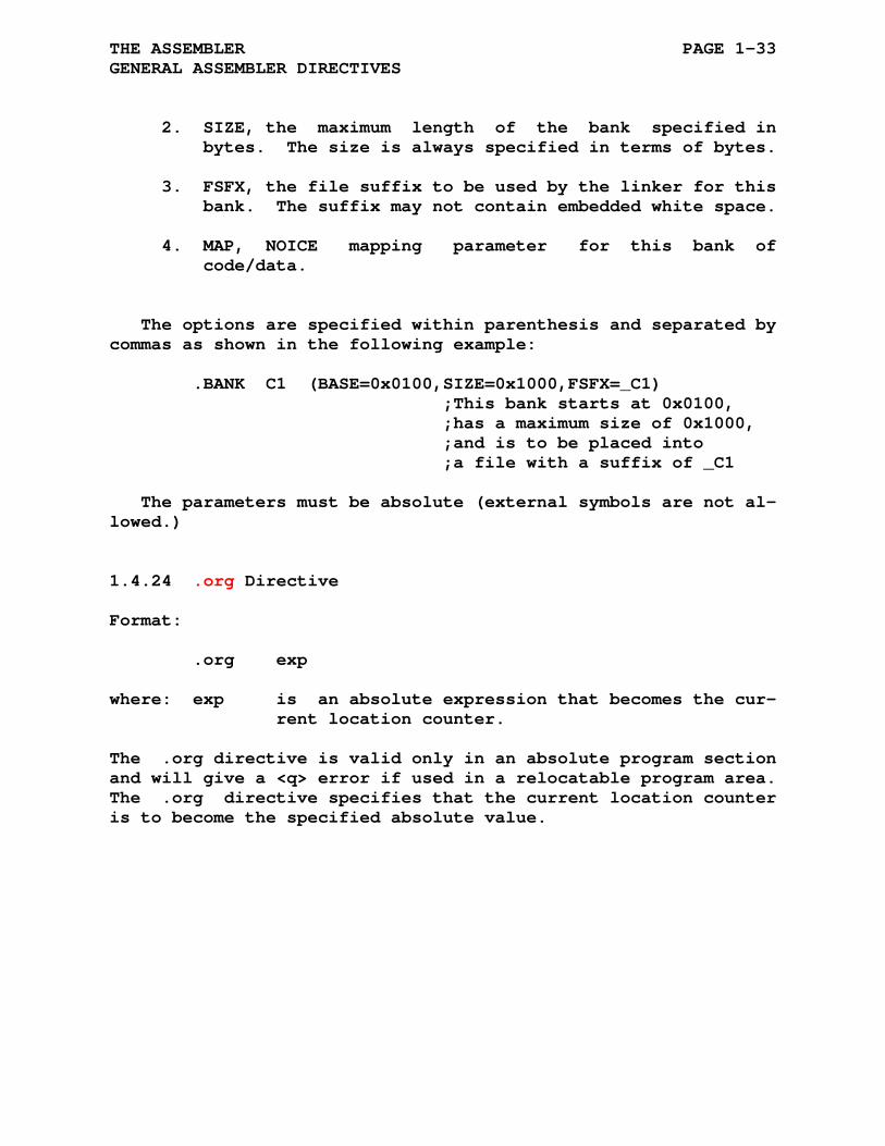
2. SIZE, the maximum length of the bank specified in bytes. The size is always specified in terms of bytes.
3. FSFX, the file suffix to be used by the linker for this bank. The suffix may not contain embedded white space.
4. MAP, NOICE mapping parameter for this bank of code/data.
The options are specified within parenthesis and separated by commas as shown in the following example:
.BANK C1 (BASE=0x0100,SIZE=0x1000,FSFX=_C1) ;This bank starts at 0x0100, ;has a maximum size of 0x1000, ;and is to be placed into ;a file with a suffix of _C1
The parameters must be absolute (external symbols are not al- lowed.)
1.4.24 .org Directive
Format:
.org exp
where: exp is an absolute expression that becomes the cur- rent location counter.
The .org directive is valid only in an absolute program section and will give a <q> error if used in a relocatable program area. The .org directive specifies that the current location counter is to become the specified absolute value.

THE ASSEMBLER PAGE 1-34 GENERAL ASSEMBLER DIRECTIVES
1.4.25 .globl Directive
Format:
.globl sym1,sym2,...,symn
where: sym1, represent legal symbolic names. sym2,... When multiple symbols are specified, symn they are separated by commas.
A .globl directive may also have a label field and/or a com- ment field.
The .globl directive is provided to export (and thus provide linkage to) symbols not otherwise defined as global symbols within a module. In exporting global symbols the directive .globl J is similar to:
J == expression or J::
Because object modules are linked by global symbols, these symbols are vital to a program. All internal symbols appearing within a given program must be defined at the end of pass 1 or they will be considered undefined. The assembly directive (-g) can be invoked to make all undefined symbols global at the end of pass 1.
The .globl directive and == construct can be overridden by a following .local directive.
NOTE
The ASxxxx assemblers use the last occurring symbol specification in the source file(s) as the type shown in the symbol table and output to the .rel file.
THE ASSEMBLER PAGE 1-35 GENERAL ASSEMBLER DIRECTIVES
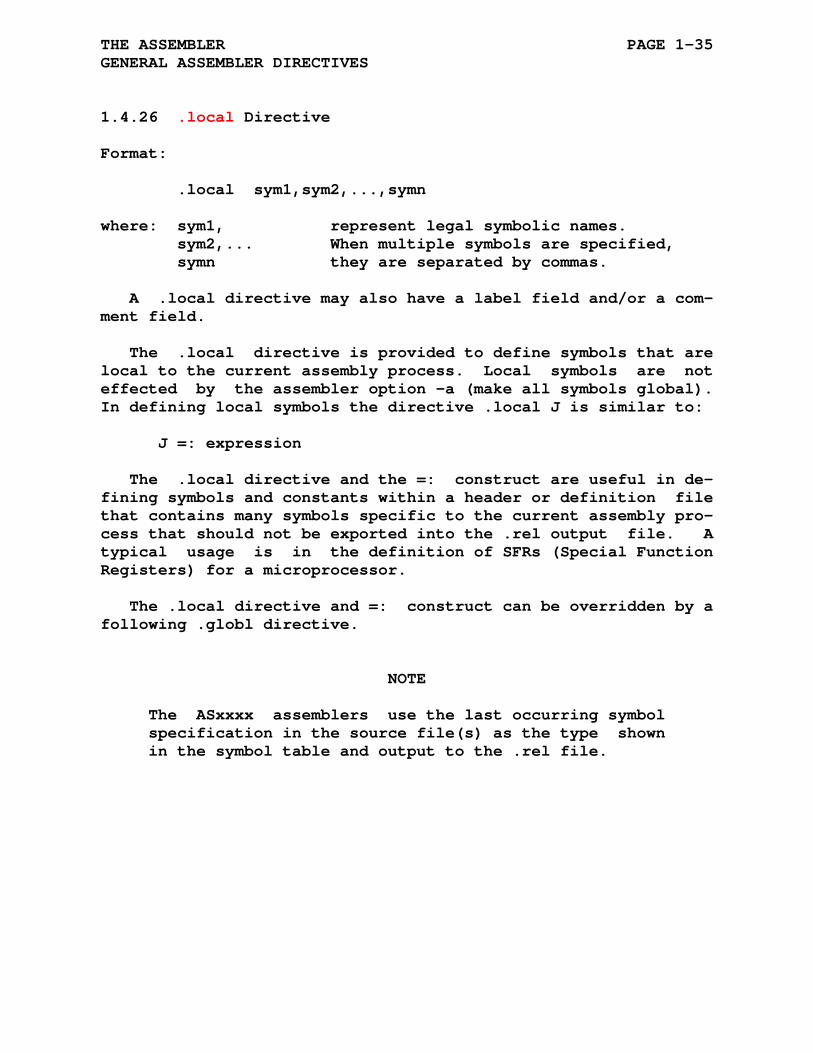
1.4.26 .local Directive
Format:
.local sym1,sym2,...,symn
where: sym1, represent legal symbolic names. sym2,... When multiple symbols are specified, symn they are separated by commas.
A .local directive may also have a label field and/or a com- ment field.
The .local directive is provided to define symbols that are local to the current assembly process. Local symbols are not effected by the assembler option -a (make all symbols global). In defining local symbols the directive .local J is similar to:
J =: expression
The .local directive and the =: construct are useful in de- fining symbols and constants within a header or definition file that contains many symbols specific to the current assembly pro- cess that should not be exported into the .rel output file. A typical usage is in the definition of SFRs (Special Function Registers) for a microprocessor.
The .local directive and =: construct can be overridden by a following .globl directive.
NOTE
The ASxxxx assemblers use the last occurring symbol specification in the source file(s) as the type shown in the symbol table and output to the .rel file.

THE ASSEMBLER PAGE 1-36 GENERAL ASSEMBLER DIRECTIVES
1.4.27 .equ, .gblequ, and .lclequ Directives
Format:
sym1 .equ expr ; equivalent to sym1 = expr sym2 .gblequ expr ; equivalent to sym2 == expr sym3 .lclequ expr ; equivalent to sym3 =: expr or .equ sym1, expr ; equivalent to sym1 = expr .gblequ sym2, expr ; equivalent to sym2 == expr .lclequ sym3, expr ; equivalent to sym3 =: expr
These alternate forms of equivalence are provided for user convenience.
1.4.28 .if, .else, and .endif Directives
Format:
.if expr . ;} . ;} range of true condition . ;} .else . ;} . ;} range of false condition . ;} .endif
The conditional assembly directives allow you to include or exclude blocks of source code during the assembly process, based on the evaluation of the test condition.
The range of true condition will be processed if the expres- sion 'expr' is not zero (i.e. true) and the range of false con- dition will be processed if the expression 'expr' is zero (i.e false). The range of true condition is optional as is the .else directive and the range of false condition. The following are all valid .if/.else/.endif constructions:
.if A-4 ;evaluate A-4 .byte 1,2 ;insert bytes if A-4 is .endif ;not zero .if K+3 ;evaluate K+3 .else

THE ASSEMBLER PAGE 1-37 GENERAL ASSEMBLER DIRECTIVES
.byte 3,4 ;insert bytes if K+3 .endif ;is zero .if J&3 ;evaluate J masked by 3 .byte 12 ;insert this byte if J&3 .else ;is not zero .byte 13 ;insert this byte if J&3 .endif ;is zero
All .if/.else/.endif directives are limited to a maximum nesting of 10 levels.
The use of a .else directive outside a .if/.endif block will generate an <i> error. Assemblies having unequal .if and .endif counts will cause an <i> error.
1.4.29 .iff, .ift, and .iftf Directives
Format:
.if expr ;'if' range Condition is ;TRUE when expr is not zero .ift ;} . ;} range of true condition ;} .iff ;} if . ;} range of false condition ;} block .iftf ;} . ;} unconditional range ;} .else ;'else' range Condition is ;TRUE when expr is zero .ift ;} . ;} range of true condition ;} .iff ;} else . ;} range of false condition ;} block .iftf ;} . ;} unconditional range ;} .endif
The subconditional assembly directives may be placed within conditional assembly blocks to indicate:
1. The assembly of an alternate body of code when the condition of the block tests false. 2. The assembly of non-contiguous body of code within the conditional assembly block, depending upon the result of the conditional
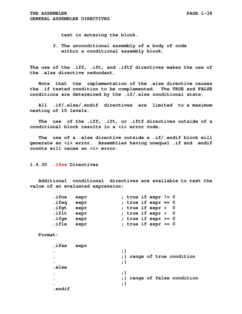
THE ASSEMBLER PAGE 1-38 GENERAL ASSEMBLER DIRECTIVES
test in entering the block. 3. The unconditional assembly of a body of code within a conditional assembly block.
The use of the .iff, .ift, and .iftf directives makes the use of the .else directive redundant.
Note that the implementation of the .else directive causes the .if tested condition to be complemented. The TRUE and FALSE conditions are determined by the .if/.else conditional state.
All .if/.else/.endif directives are limited to a maximum nesting of 10 levels.
The use of the .iff, .ift, or .iftf directives outside of a conditional block results in a <i> error code.
The use of a .else directive outside a .if/.endif block will generate an <i> error. Assemblies having unequal .if and .endif counts will cause an <i> error.
1.4.30 .ifxx Directives
Additional conditional directives are available to test the value of an evaluated expression:
.ifne expr ; true if expr != 0 .ifeq expr ; true if expr == 0 .ifgt expr ; true if expr > 0 .iflt expr ; true if expr < 0 .ifge expr ; true if expr >= 0 .ifle expr ; true if expr <= 0
Format:
.ifxx expr . ;} . ;} range of true condition . ;} .else . ;} . ;} range of false condition . ;} .endif

THE ASSEMBLER PAGE 1-39 GENERAL ASSEMBLER DIRECTIVES
The conditional assembly directives allow you to include or exclude blocks of source code during the assembly process, based on the evaluation of the test condition.
The range of true condition will be processed if the expres- sion 'expr' is not zero (i.e. true) and the range of false con- dition will be processed if the expression 'expr' is zero (i.e false). The range of true condition is optional as is the .else directive and the range of false condition. The following are all valid .ifxx/.else/.endif constructions:
.ifne A-4 ;evaluate A-4 .byte 1,2 ;insert bytes if A-4 is .endif ;not zero .ifeq K+3 ;evaluate K+3 .byte 3,4 ;insert bytes if K+3 .endif ;is zero .ifne J&3 ;evaluate J masked by 3 .byte 12 ;insert this byte if J&3 .else ;is not zero .byte 13 ;insert this byte if J&3 .endif ;is zero
All .if/.else/.endif directives are limited to a maximum nesting of 10 levels.
The use of a .else directive outside a .if/.endif block will generate an <i> error. Assemblies having unequal .if and .endif counts will cause an <i> error.
1.4.31 .ifdef Directive
Format:
.ifdef sym . ;} . ;} range of true condition . ;} .else . ;} . ;} range of false condition . ;} .endif

THE ASSEMBLER PAGE 1-40 GENERAL ASSEMBLER DIRECTIVES
The conditional assembly directives allow you to include or exclude blocks of source code during the assembly process, based on the evaluation of the test condition.
The range of true condition will be processed if the symbol 'sym' has been defined with a .define directive or 'sym' is a variable with an assigned value else the false range will be processed. The range of true condition is optional as is the .else directive and the range of false condition. The following are all valid .ifdef/.else/.endif constructions:
.ifdef sym$1 ;lookup symbol sym$1 .byte 1,2 ;insert bytes if sym$1 .endif ;is defined or ;assigned a value .ifdef sym$2 ;lookup symbol sym$2 .else .byte 3,4 ;insert bytes if sym$1 .endif ;is not defined and ;not assigned a value .ifdef sym$3 ;lookup symbol sym$3 .byte 12 ;insert this byte if sym$3 .else ;is defined/valued .byte 13 ;insert this byte if sym$3 .endif ;is not defined/valued
Note that the default assembler configuration of case sensitive means the testing for a defined symbol is also case sensitive.
All .if/.else/.endif directives are limited to a maximum nesting of 10 levels.
The use of a .else directive outside a .if/.endif block will generate an <i> error. Assemblies having unequal .if and .endif counts will cause an <i> error.

THE ASSEMBLER PAGE 1-41 GENERAL ASSEMBLER DIRECTIVES
1.4.32 .ifndef Directive
Format:
.ifndef sym . ;} . ;} range of true condition . ;} .else . ;} . ;} range of false condition . ;} .endif
The conditional assembly directives allow you to include or exclude blocks of source code during the assembly process, based on the evaluation of the condition test.
The range of true condition will be processed if the symbol 'sym' is not defined by a .define directive and a variable 'sym' has not been assigned a value else the range of false condition will be processed. The range of true condition is optional as is the .else directive and the range of false condition. The following are all valid .ifndef/.else/.endif constructions:
.ifndef sym$1 ;lookup symbol sym$1 .byte 1,2 ;insert bytes if sym$1 is .endif ;not defined and ;not assigned a value .ifndef sym$2 ;lookup symbol sym$2 .else .byte 3,4 ;insert bytes if sym$1 .endif ;is defined or ;is assigned a value .ifndef sym$3 ;lookup symbol sym$3 .byte 12 ;insert this byte if sym$3 .else ;is not defined/valued .byte 13 ;insert this byte if sym$3 .endif ;is defined/valued
All .if/.else/.endif directives are limited to a maximum nesting of 10 levels.
The use of a .else directive outside a .if/.endif block will generate an <i> error. Assemblies having unequal .if and .endif counts will cause an <i> error.
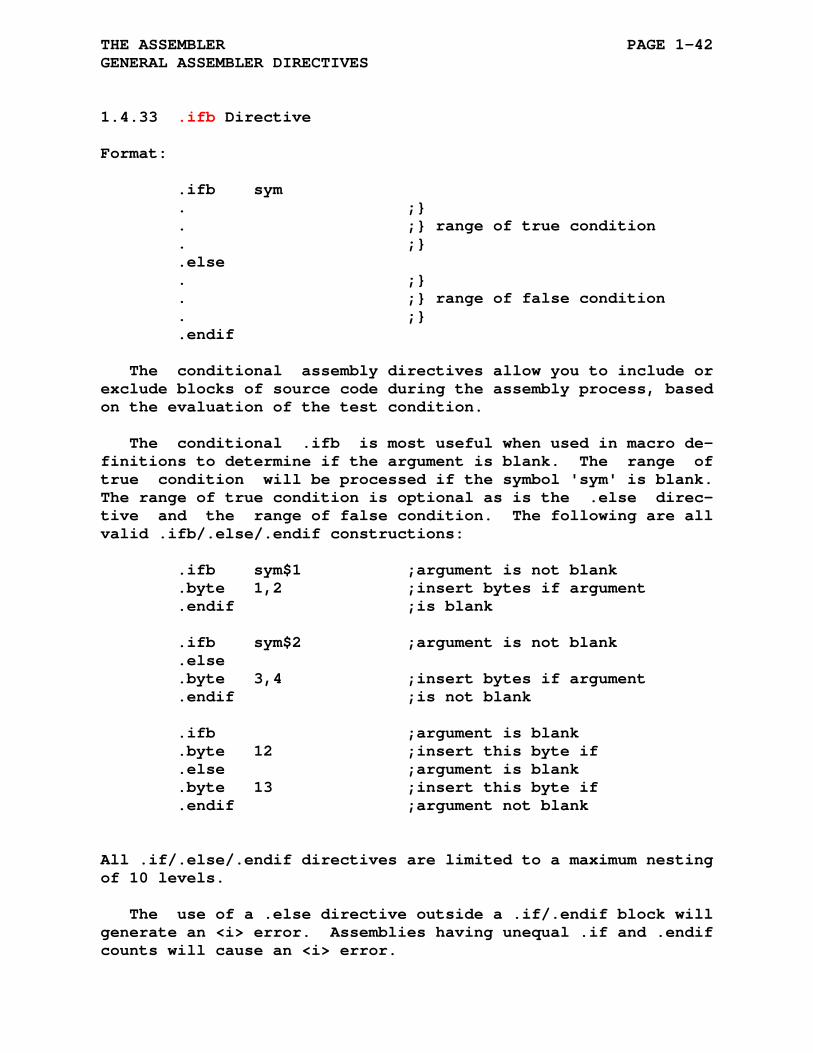
THE ASSEMBLER PAGE 1-42 GENERAL ASSEMBLER DIRECTIVES
1.4.33 .ifb Directive
Format:
.ifb sym . ;} . ;} range of true condition . ;} .else . ;} . ;} range of false condition . ;} .endif
The conditional assembly directives allow you to include or exclude blocks of source code during the assembly process, based on the evaluation of the test condition.
The conditional .ifb is most useful when used in macro de- finitions to determine if the argument is blank. The range of true condition will be processed if the symbol 'sym' is blank. The range of true condition is optional as is the .else direc- tive and the range of false condition. The following are all valid .ifb/.else/.endif constructions:
.ifb sym$1 ;argument is not blank .byte 1,2 ;insert bytes if argument .endif ;is blank .ifb sym$2 ;argument is not blank .else .byte 3,4 ;insert bytes if argument .endif ;is not blank .ifb ;argument is blank .byte 12 ;insert this byte if .else ;argument is blank .byte 13 ;insert this byte if .endif ;argument not blank
All .if/.else/.endif directives are limited to a maximum nesting of 10 levels.
The use of a .else directive outside a .if/.endif block will generate an <i> error. Assemblies having unequal .if and .endif counts will cause an <i> error.
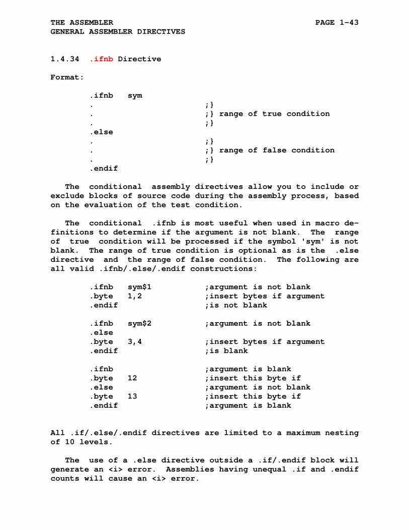
THE ASSEMBLER PAGE 1-43 GENERAL ASSEMBLER DIRECTIVES
1.4.34 .ifnb Directive
Format:
.ifnb sym . ;} . ;} range of true condition . ;} .else . ;} . ;} range of false condition . ;} .endif
The conditional assembly directives allow you to include or exclude blocks of source code during the assembly process, based on the evaluation of the test condition.
The conditional .ifnb is most useful when used in macro de- finitions to determine if the argument is not blank. The range of true condition will be processed if the symbol 'sym' is not blank. The range of true condition is optional as is the .else directive and the range of false condition. The following are all valid .ifnb/.else/.endif constructions:
.ifnb sym$1 ;argument is not blank .byte 1,2 ;insert bytes if argument .endif ;is not blank .ifnb sym$2 ;argument is not blank .else .byte 3,4 ;insert bytes if argument .endif ;is blank .ifnb ;argument is blank .byte 12 ;insert this byte if .else ;argument is not blank .byte 13 ;insert this byte if .endif ;argument is blank
All .if/.else/.endif directives are limited to a maximum nesting of 10 levels.
The use of a .else directive outside a .if/.endif block will generate an <i> error. Assemblies having unequal .if and .endif counts will cause an <i> error.
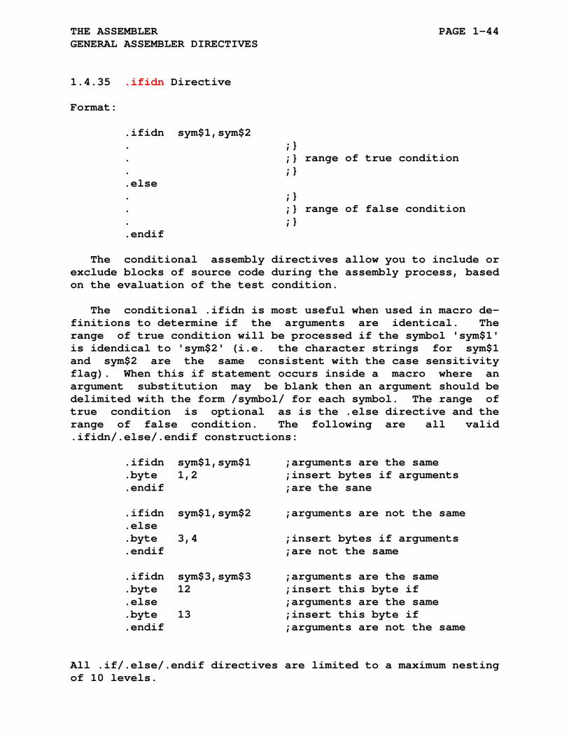
THE ASSEMBLER PAGE 1-44 GENERAL ASSEMBLER DIRECTIVES
1.4.35 .ifidn Directive
Format:
.ifidn sym$1,sym$2 . ;} . ;} range of true condition . ;} .else . ;} . ;} range of false condition . ;} .endif
The conditional assembly directives allow you to include or exclude blocks of source code during the assembly process, based on the evaluation of the test condition.
The conditional .ifidn is most useful when used in macro de- finitions to determine if the arguments are identical. The range of true condition will be processed if the symbol 'sym$1' is idendical to 'sym$2' (i.e. the character strings for sym$1 and sym$2 are the same consistent with the case sensitivity flag). When this if statement occurs inside a macro where an argument substitution may be blank then an argument should be delimited with the form /symbol/ for each symbol. The range of true condition is optional as is the .else directive and the range of false condition. The following are all valid .ifidn/.else/.endif constructions:
.ifidn sym$1,sym$1 ;arguments are the same .byte 1,2 ;insert bytes if arguments .endif ;are the sane .ifidn sym$1,sym$2 ;arguments are not the same .else .byte 3,4 ;insert bytes if arguments .endif ;are not the same .ifidn sym$3,sym$3 ;arguments are the same .byte 12 ;insert this byte if .else ;arguments are the same .byte 13 ;insert this byte if .endif ;arguments are not the same
All .if/.else/.endif directives are limited to a maximum nesting of 10 levels.
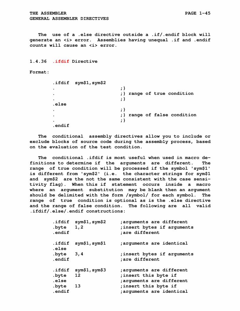
THE ASSEMBLER PAGE 1-45 GENERAL ASSEMBLER DIRECTIVES
The use of a .else directive outside a .if/.endif block will generate an <i> error. Assemblies having unequal .if and .endif counts will cause an <i> error.
1.4.36 .ifdif Directive
Format:
.ifdif sym$1,sym$2 . ;} . ;} range of true condition . ;} .else . ;} . ;} range of false condition . ;} .endif
The conditional assembly directives allow you to include or exclude blocks of source code during the assembly process, based on the evaluation of the test condition.
The conditional .ifdif is most useful when used in macro de- finitions to determine if the arguments are different. The range of true condition will be processed if the symbol 'sym$1' is different from 'sym$2' (i.e. the character strings for sym$1 and sym$2 are the not the same consistent with the case sensi- tivity flag). When this if statement occurs inside a macro where an argument substitution may be blank then an argument should be delimited with the form /symbol/ for each symbol. The range of true condition is optional as is the .else directive and the range of false condition. The following are all valid .ifdif/.else/.endif constructions:
.ifdif sym$1,sym$2 ;arguments are different .byte 1,2 ;insert bytes if arguments .endif ;are different .ifdif sym$1,sym$1 ;arguments are identical .else .byte 3,4 ;insert bytes if arguments .endif ;are different .ifdif sym$1,sym$3 ;arguments are different .byte 12 ;insert this byte if .else ;arguments are different .byte 13 ;insert this byte if .endif ;arguments are identical

THE ASSEMBLER PAGE 1-46 GENERAL ASSEMBLER DIRECTIVES
All .if/.else/.endif directives are limited to a maximum nesting of 10 levels.
The use of a .else directive outside a .if/.endif block will generate an <i> error. Assemblies having unequal .if and .endif counts will cause an <i> error.
1.4.37 Alternate .if Directive Forms
Format:
.if cnd(,) arg1(, arg2)
where the cnd (followed by an optional comma) may be any of the following:
------------------------------------------------------- condition Assemble (complement) Args Block if: ------------------------------------------------------- eq ( ne ) expr equal to zero (not equal to zero) gt ( le ) expr greater than zero (less than or equal to zero) lt ( ge ) expr less than zero (greater than or equal to zero) def ( ndef ) symbol .define'd or user set (not .define'd or user set) b ( nb ) macro argument present symbol (argument not present) idn ( dif ) macro arguments identical symbol (arguments not identical) f ( t ) ----- only within a .if/.else/.endif conditional block tf ----- only within a .if/.else/.endif conditional block
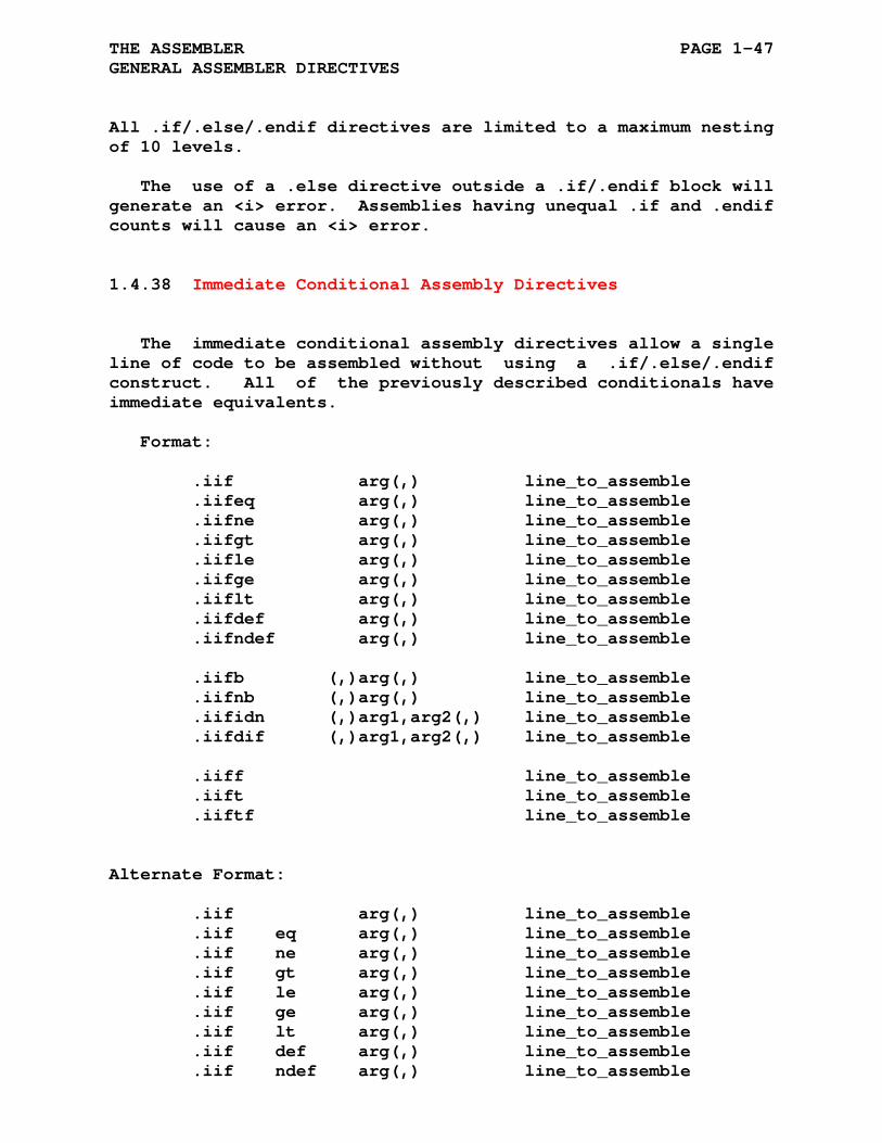
THE ASSEMBLER PAGE 1-47 GENERAL ASSEMBLER DIRECTIVES
All .if/.else/.endif directives are limited to a maximum nesting of 10 levels.
The use of a .else directive outside a .if/.endif block will generate an <i> error. Assemblies having unequal .if and .endif counts will cause an <i> error.
1.4.38 Immediate Conditional Assembly Directives
The immediate conditional assembly directives allow a single line of code to be assembled without using a .if/.else/.endif construct. All of the previously described conditionals have immediate equivalents.
Format:
.iif arg(,) line_to_assemble .iifeq arg(,) line_to_assemble .iifne arg(,) line_to_assemble .iifgt arg(,) line_to_assemble .iifle arg(,) line_to_assemble .iifge arg(,) line_to_assemble .iiflt arg(,) line_to_assemble .iifdef arg(,) line_to_assemble .iifndef arg(,) line_to_assemble .iifb (,)arg(,) line_to_assemble .iifnb (,)arg(,) line_to_assemble .iifidn (,)arg1,arg2(,) line_to_assemble .iifdif (,)arg1,arg2(,) line_to_assemble .iiff line_to_assemble .iift line_to_assemble .iiftf line_to_assemble
Alternate Format:
.iif arg(,) line_to_assemble .iif eq arg(,) line_to_assemble .iif ne arg(,) line_to_assemble .iif gt arg(,) line_to_assemble .iif le arg(,) line_to_assemble .iif ge arg(,) line_to_assemble .iif lt arg(,) line_to_assemble .iif def arg(,) line_to_assemble .iif ndef arg(,) line_to_assemble
THE ASSEMBLER PAGE 1-48 GENERAL ASSEMBLER DIRECTIVES
.iif b (,)arg(,) line_to_assemble .iif nb (,)arg(,) line_to_assemble .iif idn (,)arg1,arg2(,) line_to_assemble .iif dif (,)arg1,arg2(,) line_to_assemble .iiff line_to_assemble .iift line_to_assemble .iiftf line_to_assemble
The (,) indicates an optional comma.
The .iif types b, n, idn, and dif require the commas if the argument(s) may be blank. These commas may be removed if the arguments are delimited with the form ^/symbol/ for each symbol.
The immediate conditional directives donot change the .if/.else/.endif nesting level.
1.4.39 .include Directive
Format:
.include /string/ or
.include ^/string/
where: string represents a string that is the file specifica- tion of an ASxxxx source file.
/ / represent the delimiting characters. These delimiters may be any paired printing characters, as long as the characters are not contained within the string itself. If the delimiting characters do not match, the .include directive will give the <q> error.
The .include directive is used to insert a source file within the source file currently being assembled. When this directive is encountered, an implicit .page directive is issued. When the end of the specified source file is reached, an implicit .page directive is issued and input continues from the previous source file. The maximum nesting level of source files specified by a .include directive is five.
THE ASSEMBLER PAGE 1-49 GENERAL ASSEMBLER DIRECTIVES
The total number of separately specified .include files is unlimited as each .include file is opened and then closed during each pass made by the assembler.
The default directory path, if none is specified, for any .include file is the directory path of the current file. For example: if the current source file, D:\proj\file1.asm, in- cludes a file specified as "include1" then the file D:\proj\include1.asm is opened.

THE ASSEMBLER PAGE 1-50
GENERAL ASSEMBLER DIRECTIVES
1.4.39.1 Including Files In Windows/DOS -
Graphical Illustration of Include File Locations
for the following command line entry:
__> bin\ascheck -l -o -s obj\prjct.rel src\prjct\prjct.asm
/-----------------------------------------------------------------------\
| (rooted) |
_____ | _____ |
| | | | | |
---| inc | <---/ ---| bin | |
| |_____| | |_____| |
| | | | |
| \___ inc4.asm | \___ ascheck.exe |
| | |
| | |
_____ | _____ _____ | _____ _____ |
| | | | | | | | | | | | (in prjct.asm directory) |
| C:\ |-----| ..\ |-----| __> |--+--| src |-----|prjct| <-------------------------------\ |
|_____| |_____| | |_____| | |_____| | |_____| | |
| | | | .include "inc1.asm" -/ |
| ^ | | \___ prjct.asm .include "C:\inc\inc4.asm" --/
| | | | \___ inc1.asm .include "..\inc\inc3.asm" -------\
Current | | | | _____ .include "src\inc\inc2.asm" -\ |
Working ------> | >---/ | | | | | |
Directory | | ---| inc | <---------------------------------------/ |
| | |_____| (relative to current working directory) |
| | | |
| | \___ inc2.asm |
| | _____ |
| | | | |
| ---| obj | |
| |_____| |
| | |
| \___ .REL, .SYM, .LST, .HLR |
| |
| _____ |
| | | (relative to current working directory) |
---| inc | <--------------------------------------------------------------------/
|_____|
|
\___ inc3.asm
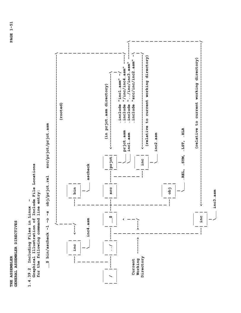
THE ASSEMBLER PAGE 1-51
GENERAL ASSEMBLER DIRECTIVES
1.4.39.2 Including Files in Linux -
Graphical Illustration of Include File Locations
for the following command line entry:
__$ bin/ascheck -l -o -s obj/prjct.rel src/prjct/prjct.asm
/-----------------------------------------------------------------------\
| (rooted) |
_____ | _____ |
| | | | | |
---| inc | <---/ ---| bin | |
| |_____| | |_____| |
| | | | |
| \___ inc4.asm | \___ ascheck |
| | |
| | |
_____ | _____ _____ | _____ _____ |
| | | | | | | | | | | | (in prjct.asm directory) |
| / |-----| ../ |-----| __$ |--+--| src |-----|prjct| <-------------------------------\ |
|_____| |_____| | |_____| | |_____| | |_____| | |
| | | | .include "inc1.asm" -/ |
| ^ | | \___ prjct.asm .include "/inc/inc4.asm" ----/
| | | | \___ inc1.asm .include "../inc/inc3.asm" -------\
Current | | | | _____ .include "src/inc/inc2.asm" -\ |
Working ------> | >---/ | | | | | |
Directory | | ---| inc | <---------------------------------------/ |
| | |_____| (relative to current working directory) |
| | | |
| | \___ inc2.asm |
| | _____ |
| | | | |
| ---| obj | |
| |_____| |
| | |
| \___ .REL, .SYM, .LST, .HLR |
| |
| _____ |
| | | (relative to current working directory) |
---| inc | <--------------------------------------------------------------------/
|_____|
|
\___ inc3.asm
THE ASSEMBLER PAGE 1-52 GENERAL ASSEMBLER DIRECTIVES
1.4.40 .define and .undefine Directives
Format:
.define keyword /string/ or
.define keyword ^/string/
.undefine keyword
where: keyword is the substitutable string which must start with a letter and may contain any combination of digits and letters.
where: string represents a string that is substituted for the keyword. The string may contain any sequence of characters including white space.
/ / represent the delimiting characters. These delimiters may be any paired printing characters, as long as the characters are not contained within the string itself. If the delimiting characters do not match, the .define directive will give the <q> error.
The .define directive specifies a user defined string which is substituted for the keyword. The substitution string may it- self contain other keywords that are substitutable. The assem- bler resumes the parse of the line at the point the keyword was found. Care must be excersized to avoid any circular references within .define directives, otherwise the assembler may enter a 'recursion runaway' resulting in an <s> error.
The .undefine directive removes the keyword as a substitut- able string. No error is returned if the keyword was not de- fined.
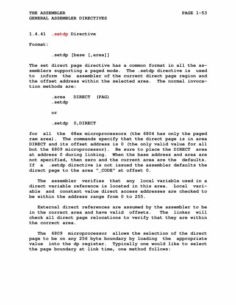
THE ASSEMBLER PAGE 1-53 GENERAL ASSEMBLER DIRECTIVES
1.4.41 .setdp Directive
Format:
.setdp [base [,area]]
The set direct page directive has a common format in all the as- semblers supporting a paged mode. The .setdp directive is used to inform the assembler of the current direct page region and the offset address within the selected area. The normal invoca- tion methods are:
.area DIRECT (PAG) .setdp or .setdp 0,DIRECT
for all the 68xx microprocessors (the 6804 has only the paged ram area). The commands specify that the direct page is in area DIRECT and its offset address is 0 (the only valid value for all but the 6809 microprocessor). Be sure to place the DIRECT area at address 0 during linking. When the base address and area are not specified, then zero and the current area are the defaults. If a .setdp directive is not issued the assembler defaults the direct page to the area "_CODE" at offset 0.
The assembler verifies that any local variable used in a direct variable reference is located in this area. Local vari- able and constant value direct access addresses are checked to be within the address range from 0 to 255.
External direct references are assumed by the assembler to be in the correct area and have valid offsets. The linker will check all direct page relocations to verify that they are within the correct area.
The 6809 microprocessor allows the selection of the direct page to be on any 256 byte boundary by loading the appropriate value into the dp register. Typically one would like to select the page boundary at link time, one method follows:
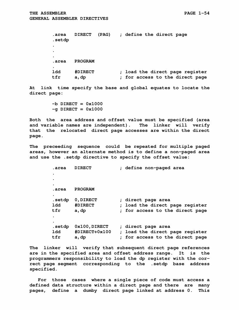
THE ASSEMBLER PAGE 1-54 GENERAL ASSEMBLER DIRECTIVES
.area DIRECT (PAG) ; define the direct page .setdp . . . .area PROGRAM . ldd #DIRECT ; load the direct page register tfr a,dp ; for access to the direct page
At link time specify the base and global equates to locate the direct page:
-b DIRECT = 0x1000 -g DIRECT = 0x1000
Both the area address and offset value must be specified (area and variable names are independent). The linker will verify that the relocated direct page accesses are within the direct page.
The preceeding sequence could be repeated for multiple paged areas, however an alternate method is to define a non-paged area and use the .setdp directive to specify the offset value:
.area DIRECT ; define non-paged area . . . .area PROGRAM . .setdp 0,DIRECT ; direct page area ldd #DIRECT ; load the direct page register tfr a,dp ; for access to the direct page . . .setdp 0x100,DIRECT ; direct page area ldd #DIRECT+0x100 ; load the direct page register tfr a,dp ; for access to the direct page
The linker will verify that subsequent direct page references are in the specified area and offset address range. It is the programmers responsibility to load the dp register with the cor- rect page segment corresponding to the .setdp base address specified.
For those cases where a single piece of code must access a defined data structure within a direct page and there are many pages, define a dumby direct page linked at address 0. This
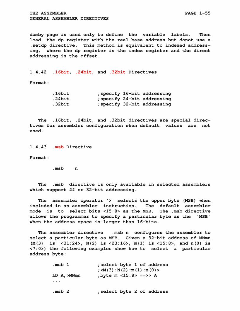
THE ASSEMBLER PAGE 1-55 GENERAL ASSEMBLER DIRECTIVES
dumby page is used only to define the variable labels. Then load the dp register with the real base address but donot use a .setdp directive. This method is equivalent to indexed address- ing, where the dp register is the index register and the direct addressing is the offset.
1.4.42 .16bit, .24bit, and .32bit Directives
Format:
.16bit ;specify 16-bit addressing .24bit ;specify 24-bit addressing .32bit ;specify 32-bit addressing
The .16bit, .24bit, and .32bit directives are special direc- tives for assembler configuration when default values are not used.
1.4.43 .msb Directive
Format:
.msb n
The .msb directive is only available in selected assemblers which support 24 or 32-bit addressing.
The assembler operator '>' selects the upper byte (MSB) when included in an assembler instruction. The default assembler mode is to select bits <15:8> as the MSB. The .msb directive allows the programmer to specify a particular byte as the 'MSB' when the address space is larger than 16-bits.
The assembler directive .msb n configures the assembler to select a particular byte as MSB. Given a 32-bit address of MNmn (M(3) is <31:24>, N(2) is <23:16>, m(1) is <15:8>, and n(0) is <7:0>) the following examples show how to select a particular address byte:
.msb 1 ;select byte 1 of address ;<M(3):N(2):m(1):n(0)> LD A,>MNmn ;byte m <15:8> ==>> A ... .msb 2 ;select byte 2 of address
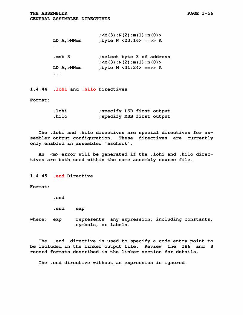
THE ASSEMBLER PAGE 1-56 GENERAL ASSEMBLER DIRECTIVES
;<M(3):N(2):m(1):n(0)> LD A,>MNmn ;byte N <23:16> ==>> A ... .msb 3 ;select byte 3 of address ;<M(3):N(2):m(1):n(0)> LD A,>MNmn ;byte M <31:24> ==>> A ...
1.4.44 .lohi and .hilo Directives
Format:
.lohi ;specify LSB first output .hilo ;specify MSB first output
The .lohi and .hilo directives are special directives for as- sembler output configuration. These directives are currently only enabled in assembler 'ascheck'.
An <m> error will be generated if the .lohi and .hilo direc- tives are both used within the same assembly source file.
1.4.45 .end Directive
Format:
.end
.end exp
where: exp represents any expression, including constants, symbols, or labels.
The .end directive is used to specify a code entry point to be included in the linker output file. Review the I86 and S record formats described in the linker section for details.
The .end directive without an expression is ignored.

THE ASSEMBLER PAGE 1-57 GENERAL ASSEMBLER DIRECTIVES
1.5 INVOKING ASXXXX
Starting an ASxxxx assembler without any arguments provides the following option list and then exits:
Usage: [-Options] [-Option with arg] file Usage: [-Options] [-Option with arg] outfile file1 [file2 ...] -h or NO ARGUMENTS Show this help list Output: -l Create list file/outfile[.lst] -o Create object file/outfile[.rel] -s Create symbol file/outfile[.sym] Listing: -d Decimal listing -q Octal listing -x Hex listing (default) -b Display .define substitutions in listing -bb and display without .define substitutions -c Disable instruction cycle count in listing -f Flag relocatable references by ` in listing file -ff Flag relocatable references by mode in listing file -p Disable automatic listing pagination -u Disable .list/.nlist processing -w Wide listing format for symbol table Assembly: -i Insert assembler line before input file(s) -v Enable out of range signed / unsigned errors Symbols: -a All user symbols made global -g Undefined symbols made global -z Disable case sensitivity for symbols "Debugging: -j Enable NoICE Debug Symbols -y Enable SDCC Debug Symbols
The ASxxxx assemblers are command line oriented. Most sytems require the option(s) and file(s) arguments to follow the ASxxxx assembler name:
as6809 -[Options] file as6809 [-Options] outfile file1 [file2 ...]
Some systems may request the arguments after the assembler is started at a system specific prompt:
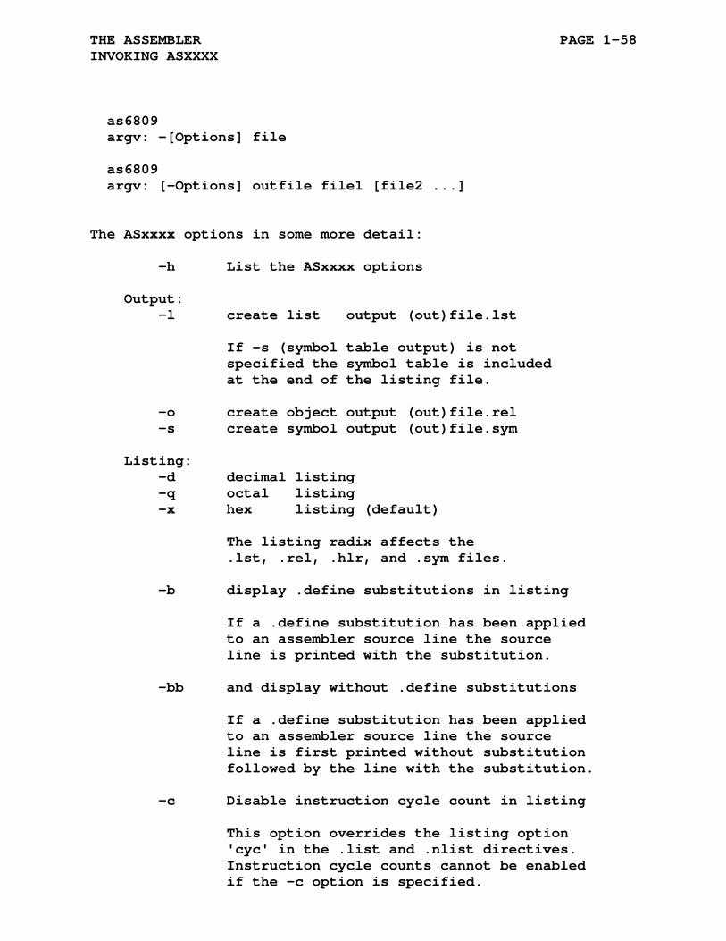
THE ASSEMBLER PAGE 1-58 INVOKING ASXXXX
as6809 argv: -[Options] file as6809 argv: [-Options] outfile file1 [file2 ...]
The ASxxxx options in some more detail:
-h List the ASxxxx options Output: -l create list output (out)file.lst If -s (symbol table output) is not specified the symbol table is included at the end of the listing file. -o create object output (out)file.rel -s create symbol output (out)file.sym Listing: -d decimal listing -q octal listing -x hex listing (default) The listing radix affects the .lst, .rel, .hlr, and .sym files. -b display .define substitutions in listing If a .define substitution has been applied to an assembler source line the source line is printed with the substitution. -bb and display without .define substitutions If a .define substitution has been applied to an assembler source line the source line is first printed without substitution followed by the line with the substitution. -c Disable instruction cycle count in listing This option overrides the listing option 'cyc' in the .list and .nlist directives. Instruction cycle counts cannot be enabled if the -c option is specified.

THE ASSEMBLER PAGE 1-59 INVOKING ASXXXX
-f by ` in the listing file -ff by mode in the listing file Relocatable modes are flagged by byte position (LSB, Byte 2, Byte 3, MSB) *nMN paged, uvUV unsigned, rsRS signed, pqPQ program counter relative. -p disable listing pagination This option inhibits the generation of a form-feed character and its associated page header in the assembler listing. -u disable .list/.nlist processing This option disables all .list and .nlist directives. The listing mode is .list with the options err, loc, bin, eqt, cyc, lin, src, pag, lst, and md. The options cyc and pag are overridden by the -c and -p command line options. -w wide listing format for symbol table Assembly: -i Insert assembler line before input file(s) This option inserts an assembly source line before the first file to be assembled. e.g.: -i BUILD=2 If the insert contains white space then delimit the insert. Inserted lines are by default not listed. To list an inserted line preceed the insert with a .list insert. e.g.: -i .list -i BUILD=2 -v Enable out of range signed / unsigned errors This option enables checking for out of range signed / unsigned values in symbol equates and arithmetic operations. This option has some ambiguities as internally the assemblers use unsigned arithmetic
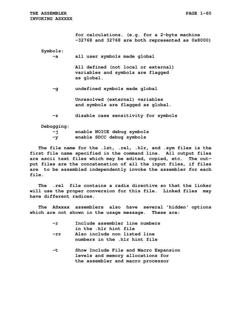
THE ASSEMBLER PAGE 1-60 INVOKING ASXXXX
for calculations. (e.g. for a 2-byte machine -32768 and 32768 are both represented as 0x8000) Symbols: -a all user symbols made global All defined (not local or external) variables and symbols are flagged as global. -g undefined symbols made global Unresolved (external) variables and symbols are flagged as global. -z disable case sensitivity for symbols Debugging: -j enable NOICE debug symbols -y enable SDCC debug symbols
The file name for the .lst, .rel, .hlr, and .sym files is the first file name specified in the command line. All output files are ascii text files which may be edited, copied, etc. The out- put files are the concatenation of all the input files, if files are to be assembled independently invoke the assembler for each file.
The .rel file contains a radix directive so that the linker will use the proper conversion for this file. Linked files may have different radices.
The ASxxxx assemblers also have several 'hidden' options which are not shown in the usage message. These are:
-r Include assembler line numbers in the .hlr hint file -rr Also include non listed line numbers in the .hlr hint file -t Show Include File and Macro Expansion levels and memory allocations for the assembler and macro processor
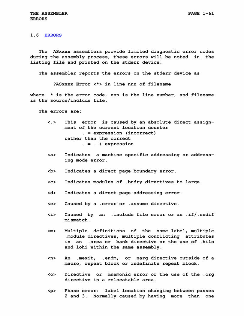
THE ASSEMBLER PAGE 1-61 ERRORS
1.6 ERRORS
The ASxxxx assemblers provide limited diagnostic error codes during the assembly process, these errors will be noted in the listing file and printed on the stderr device.
The assembler reports the errors on the stderr device as
?ASxxxx-Error-<*> in line nnn of filename
where * is the error code, nnn is the line number, and filename is the source/include file.
The errors are:
<.> This error is caused by an absolute direct assign- ment of the current location counter . = expression (incorrect) rather than the correct . = . + expression
<a> Indicates a machine specific addressing or address- ing mode error.
<b> Indicates a direct page boundary error.
<c> Indicates modulus of .bndry directives to large.
<d> Indicates a direct page addressing error.
<e> Caused by a .error or .assume directive.
<i> Caused by an .include file error or an .if/.endif mismatch.
<m> Multiple definitions of the same label, multiple .module directives, multiple conflicting attributes in an .area or .bank directive or the use of .hilo and lohi within the same assembly.
<n> An .mexit, .endm, or .narg directive outside of a macro, repeat block or indefinite repeat block.
<o> Directive or mnemonic error or the use of the .org directive in a relocatable area.
<p> Phase error: label location changing between passes 2 and 3. Normally caused by having more than one

THE ASSEMBLER PAGE 1-62 ERRORS
level of forward referencing.
<q> Questionable syntax: missing or improper operators, terminators, or delimiters.
<r> Relocation error: logic operation attempted on a relocatable term, addition of two relocatable terms, subtraction of two relocatable terms not within the same programming area or external symbols.
<s> String Substitution / recursion error.
<u> Undefined symbol encountered during assembly.
<z> Divide by 0 or Modulus by 0 error: result is 0.
1.7 LISTING FILE
The (-l) option produces an ascii output listing file. Each page of output contains a five line header:
1. The ASxxxx program name and page number
2. Assembler Radix and Address Bits
3. Title from a .title directive (if any)
4. Subtitle from a .sbttl directive (if any)
5. Blank line
Each succeeding line contains six fields:
1. Error field (first two characters of line)
2. Current location counter
3. Generated code in byte format
4. Opcode cycles count
5. Source text line number

THE ASSEMBLER PAGE 1-63 LISTING FILE
6. Source text
The error field may contain upto 2 error flags indicating any errors encountered while assembling this line of source code.
The current location counter field displays the 16-bit, 24-bit, or 32-bit program position. This field will be in the selected radix.
The generated code follows the program location. The listing radix determines the number of bytes that will be displayed in this field. Hexidecimal listing allows six bytes of data within the field, decimal and octal allow four bytes within the field. If more than one field of data is generated from the assembly of a single line of source code, then the data field is repeated on successive lines.
The opcode cycles count is printed within the delimiters [ ] on the line with the source text. This reduces the number of generated code bytes displayed on the line with the source list- ing by one. (The -c option disables all opcode cycle listing.)
The source text line number is printed in decimal and is fol- lowed by the source text. A Source line with a .page directive is never listed. (The -u option overrides this behavior.)
Two additional options are available for printing the source line text. If the -b option is specified then the listed source line contains all the .define substitutions. If the -bb option is specified then the original source line is printed before the source line with substitutions.
Two data field options are available to flag those bytes which will be relocated by the linker. If the -f option is specified then each byte to be relocated will be preceeded by the '`' character. If the -ff option is specified then each byte to be relocated will be preceeded by one of the following characters:
1. * paged relocation
2. u low byte of unsigned word or unsigned byte
3. v high byte of unsigned word
4. p PCR low byte of word relocation or PCR byte

THE ASSEMBLER PAGE 1-64 LISTING FILE
5. q PCR high byte of word relocation
6. r low byte relocation or byte relocation
7. s high byte relocation
Assemblers which use 24-bit or 32-bit addressing use an ex- tended flagging mode:
1. * paged relocation
2. u 1st byte of unsigned value
3. v 2nd byte of unsigned value
4. U 3rd byte of unsigned value
5. V 4th byte of unsigned value
6. p PCR 1st byte of relocation value or PCR byte
7. q PCR 2nd byte of relocation value
8. P PCR 3rd byte of relocation value
9. Q PCR 4th byte of relocation value
10. r 1st byte of relocation value or byte relocation
11. s 2nd byte of relocation value
12. R 3rd byte of relocation value
13. S 4th byte of relocation value

THE ASSEMBLER PAGE 1-65 SYMBOL TABLE FILE
1.8 SYMBOL TABLE FILE
The symbol table has two parts:
1. The alphabetically sorted list of symbols and/or labels defined or referenced in the source program.
2. A list of the program areas defined during assembly of the source program.
The sorted list of symbols and/or labels contains the follow- ing information:
1. Program area number (none if absolute value or exter- nal)
2. The symbol or label
3. Directly assigned symbol is denoted with an (=) sign
4. The value of a symbol, location of a label relative to the program area base address (=0), or a **** indicat- ing the symbol or label is undefined.
5. The characters: G - global, L - local, R - relocatable, and X - external.
The list of program areas provides the correspondence between the program area numbers and the defined program areas, the size of the program areas, and the area flags (attributes).
1.9 OBJECT FILE
The object file is an ascii file containing the information needed by the linker to bind multiple object modules into a com- plete loadable memory image. The object module contains the following designators:
[XDQ][HL][234] X Hexidecimal radix D Decimal radix Q Octal radix H Most significant byte first
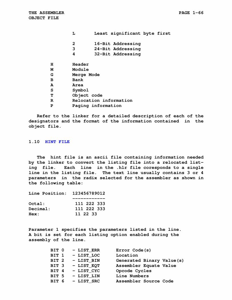
THE ASSEMBLER PAGE 1-66 OBJECT FILE
L Least significant byte first 2 16-Bit Addressing 3 24-Bit Addressing 4 32-Bit Addressing H Header M Module G Merge Mode B Bank A Area S Symbol T Object code R Relocation information P Paging information
Refer to the linker for a detailed description of each of the designators and the format of the information contained in the object file.
1.10 HINT FILE
The hint file is an ascii file containing information needed by the linker to convert the listing file into a relocated list- ing file. Each line in the .hlr file coresponds to a single line in the listing file. The text line usually contains 3 or 4 parameters in the radix selected for the assembler as shown in the following table:
Line Position: 123456789012 ------------ Octal: 111 222 333 Decimal: 111 222 333 Hex: 11 22 33 Parameter 1 specifies the parameters listed in the line. A bit is set for each listing option enabled during the assembly of the line. BIT 0 - LIST_ERR Error Code(s) BIT 1 - LIST_LOC Location BIT 2 - LIST_BIN Generated Binary Value(s) BIT 3 - LIST_EQT Assembler Equate Value BIT 4 - LIST_CYC Opcode Cycles BIT 5 - LIST_LIN Line Numbers BIT 6 - LIST_SRC Assembler Source Code
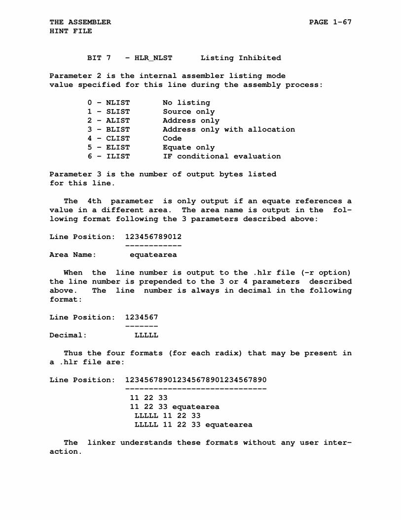
THE ASSEMBLER PAGE 1-67 HINT FILE
BIT 7 - HLR_NLST Listing Inhibited Parameter 2 is the internal assembler listing mode value specified for this line during the assembly process: 0 - NLIST No listing 1 - SLIST Source only 2 - ALIST Address only 3 - BLIST Address only with allocation 4 - CLIST Code 5 - ELIST Equate only 6 - ILIST IF conditional evaluation Parameter 3 is the number of output bytes listed for this line.
The 4th parameter is only output if an equate references a value in a different area. The area name is output in the fol- lowing format following the 3 parameters described above:
Line Position: 123456789012 ------------ Area Name: equatearea
When the line number is output to the .hlr file (-r option) the line number is prepended to the 3 or 4 parameters described above. The line number is always in decimal in the following format:
Line Position: 1234567 ------- Decimal: LLLLL
Thus the four formats (for each radix) that may be present in a .hlr file are:
Line Position: 123456789012345678901234567890 ------------------------------ 11 22 33 11 22 33 equatearea LLLLL 11 22 33 LLLLL 11 22 33 equatearea
The linker understands these formats without any user inter- action.

CHAPTER 2
THE MACRO PROCESSOR
2.1 DEFINING MACROS
By using macros a programmer can use a single line to insert a sequence of lines into a source program.
A macro definition is headed by a .macro directive followed by the source lines. The source lines may optionally contain dummy arguments. If such arguments are used, each one is listed in the .macro directive.
A macro call is the statement used by the programmer to call the macro source program. It consists of the macro name fol- lowed by the real arguments needed to replace the dummy argu- ments used in the macro.
Macro expansion is the insertion of the macro source lines into the main program. Included in this insertion is the replacement of the dummy arguments by the real arguments.
Macro directives provide a means to manipulate the macro ex- pansions. Only one directive is allowed per source line. Each directive may have a blank operand field or one or more operands. Legal operands differ with each directive. The macros and their associated directives are detailed in this chapter.
Macro directives can replace any machine dependent mnemonic associated with a specific assembler. However, the basic assem- bler directives cannot be replaced with a macro.

THE MACRO PROCESSOR PAGE 2-2 DEFINING MACROS
2.1.1 .macro Directive
Format: [label:] .macro name, dummy argument list where: label represents an optional statement label. name represents the user-assigned symbolic name of the macro. This name may be any legal symbol and may be used as a label elsewhere in the program. The macro name is not case sensitive, name, NAME, or nAmE all refer to the same macro. , represents a legal macro separator (comma, space, and/or tab). dummy represents a number of legal symbols argument that may appear anywhere in the body of list the macro definition, even as a label. These dummy symbols can be used elsewhere in the program with no conflict of definition. Multiple dummy arguments specified in this directive may be separated by any legal separator. The detection of a duplicate or an illegal symbol in a dummy argument list terminates the scan and causes a <q> error to be generated.
A comment may follow the dummy argument list in a .macro direc- tive, as shown below:
.macro abs a,b ;Defines macro abs
The first statement of a macro definition must be a .macro directive. Defining a macro with the same name as an existing macro will generate an <m> error. The .mdelete directive should be used to delete the previous macro definition before redefin- ing a macro.

THE MACRO PROCESSOR PAGE 2-3 DEFINING MACROS
2.1.2 .endm Directive
Format: .endm
The .endm directive should not have a label. Because the direc- tives .irp, .irpc, and .rept may repeat more than once the label will be defined multiple times resulting in <m> and/or <p> er- rors.
The .endm directive may be followed by a comment field, as shown below:
.endm ;end of macro
A comment may follow the dummy argument list in a .macro directive, as shown below:
.macro typemsg message ;Type a message. jsr typemsg .word message .endm ;End of typemsg
The final statement of every macro definition must be a .endm directive. The .endm directive is also used to terminate inde- finite repeat blocks and repeat blocks. A .endm directive en- countered outside a macro definition is flagged with an <n> error.
2.1.3 .mexit Directive
Format: .mexit
The .mexit directive may be used to terminate a macro expansion before the end of the macro is encountered. This directive is also legal within repeat blocks. It is most useful in nested macros. The .mexit directive terminates the current macro as though a .endm directive had been encountered. Using the .mexit directive bypasses the complexities of nested conditional direc- tives and alternate assembly paths, as shown in the following

THE MACRO PROCESSOR PAGE 2-4 DEFINING MACROS
example:
.macro altr N,A,B . . . .if eq,N ;Start conditional Block . . . .mexit ;Terminate macro expansion .endif ;End of conditional block . . . .endm ;Normal end of macro
In an assembly where the symbol N is replaced by zero, the .mexit directive would assemble the conditional block and ter- minate the macro expansion. When macros ar nested, a .mexit directive causes an exit to the next higher level of macro ex- pansion. A .mexit directive encountered outside a macro defini- tion is flagged with an <n> error.
2.2 CALLING MACROS
Format: [label:] name real arguments where: label represents an optional statement label. name represents the name of the macro, as specified in the macro definition. real represent symbolic arguments which arguments replace the dummy arguments listed in the .macro definition. When multiple arguments occur, they are separated by any legal separator. Arguments to the macro call are treated as character strings, their usage is determined by the macro definition.
A macro definition must be established by means of the .macro
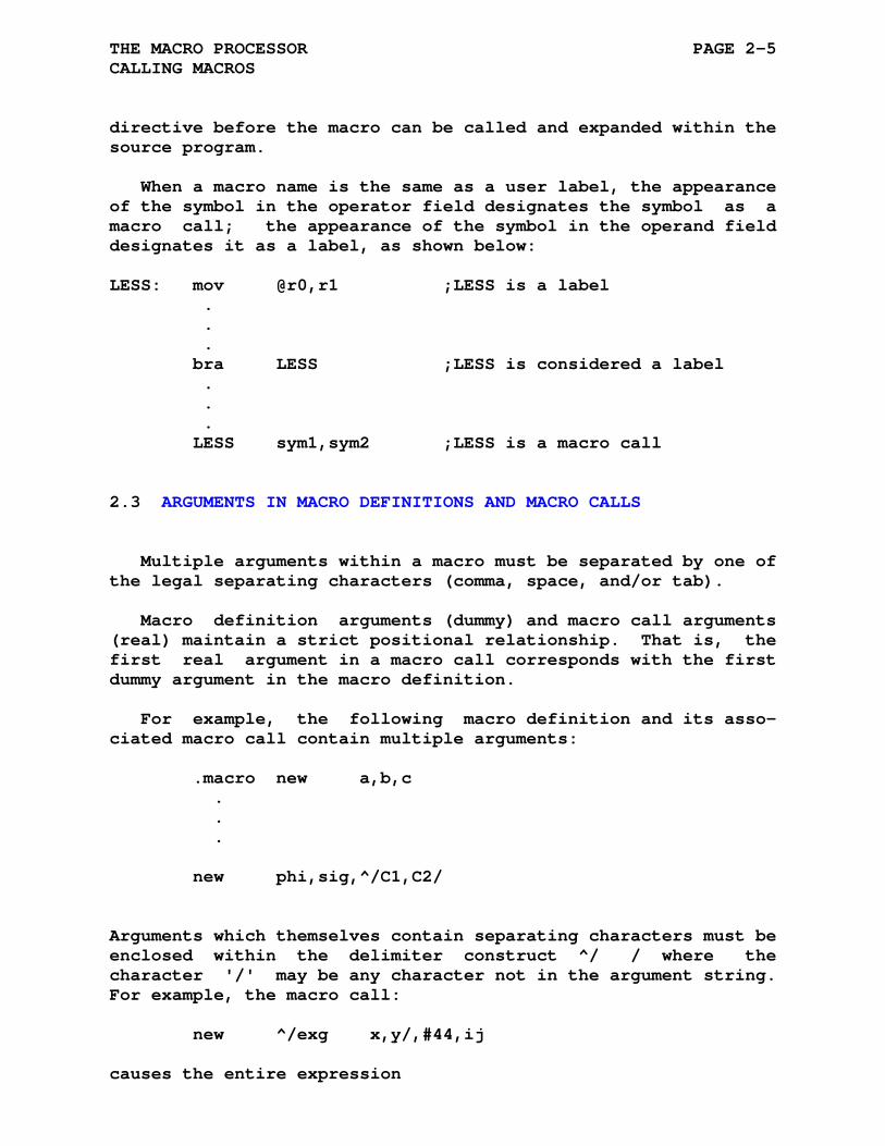
THE MACRO PROCESSOR PAGE 2-5 CALLING MACROS
directive before the macro can be called and expanded within the source program.
When a macro name is the same as a user label, the appearance of the symbol in the operator field designates the symbol as a macro call; the appearance of the symbol in the operand field designates it as a label, as shown below:
LESS: mov @r0,r1 ;LESS is a label . . . bra LESS ;LESS is considered a label . . . LESS sym1,sym2 ;LESS is a macro call
2.3 ARGUMENTS IN MACRO DEFINITIONS AND MACRO CALLS
Multiple arguments within a macro must be separated by one of the legal separating characters (comma, space, and/or tab).
Macro definition arguments (dummy) and macro call arguments (real) maintain a strict positional relationship. That is, the first real argument in a macro call corresponds with the first dummy argument in the macro definition.
For example, the following macro definition and its asso- ciated macro call contain multiple arguments:
.macro new a,b,c . . . new phi,sig,^/C1,C2/
Arguments which themselves contain separating characters must be enclosed within the delimiter construct ^/ / where the character '/' may be any character not in the argument string. For example, the macro call:
new ^/exg x,y/,#44,ij
causes the entire expression
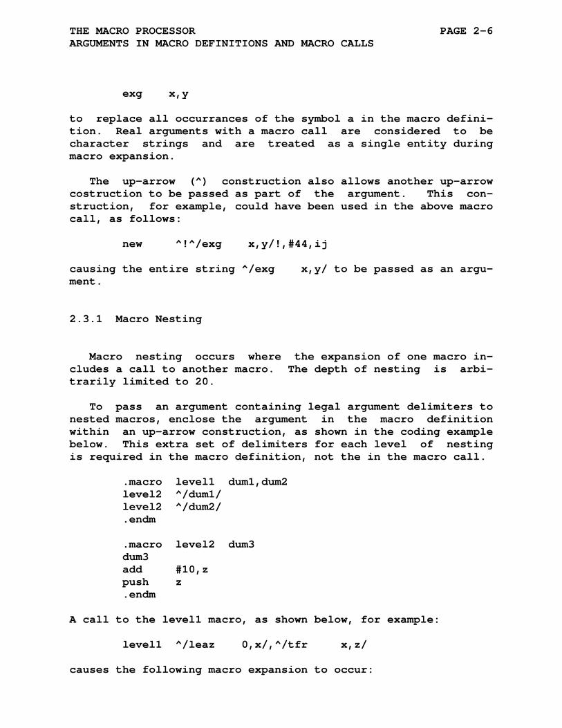
THE MACRO PROCESSOR PAGE 2-6 ARGUMENTS IN MACRO DEFINITIONS AND MACRO CALLS
exg x,y
to replace all occurrances of the symbol a in the macro defini- tion. Real arguments with a macro call are considered to be character strings and are treated as a single entity during macro expansion.
The up-arrow (^) construction also allows another up-arrow costruction to be passed as part of the argument. This con- struction, for example, could have been used in the above macro call, as follows:
new ^!^/exg x,y/!,#44,ij
causing the entire string ^/exg x,y/ to be passed as an argu- ment.
2.3.1 Macro Nesting
Macro nesting occurs where the expansion of one macro in- cludes a call to another macro. The depth of nesting is arbi- trarily limited to 20.
To pass an argument containing legal argument delimiters to nested macros, enclose the argument in the macro definition within an up-arrow construction, as shown in the coding example below. This extra set of delimiters for each level of nesting is required in the macro definition, not the in the macro call.
.macro level1 dum1,dum2 level2 ^/dum1/ level2 ^/dum2/ .endm .macro level2 dum3 dum3 add #10,z push z .endm
A call to the level1 macro, as shown below, for example:
level1 ^/leaz 0,x/,^/tfr x,z/
causes the following macro expansion to occur:
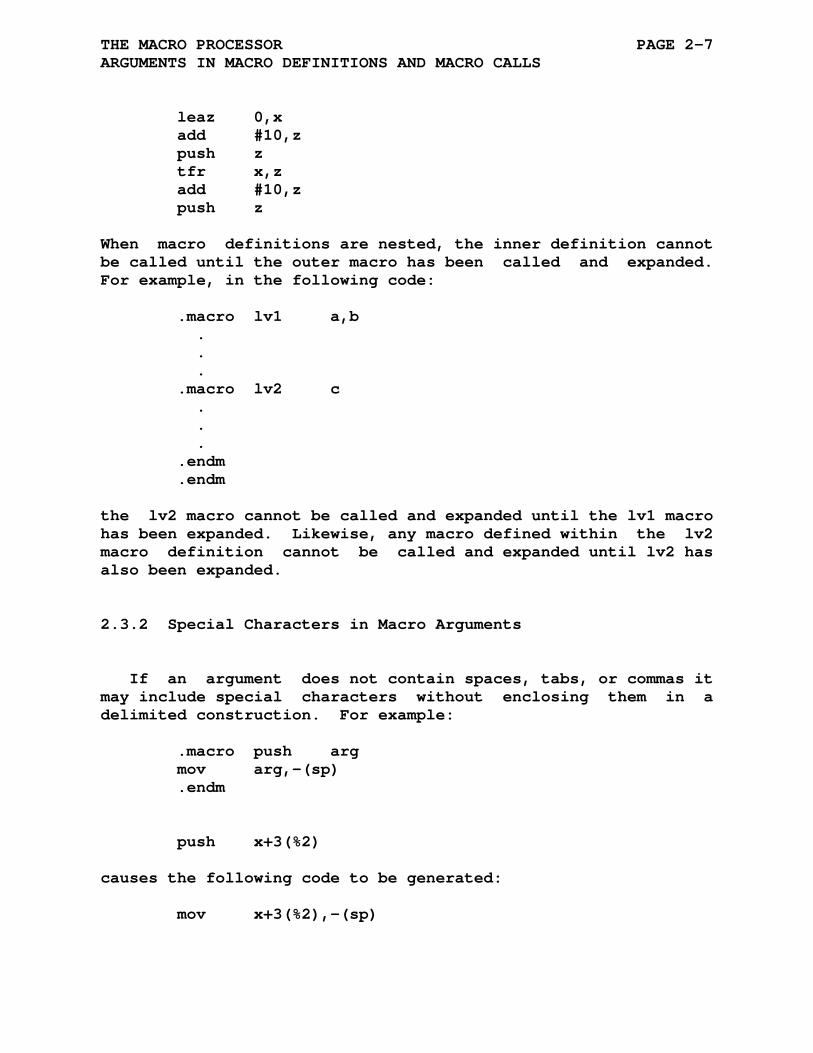
THE MACRO PROCESSOR PAGE 2-7 ARGUMENTS IN MACRO DEFINITIONS AND MACRO CALLS
leaz 0,x add #10,z push z tfr x,z add #10,z push z
When macro definitions are nested, the inner definition cannot be called until the outer macro has been called and expanded. For example, in the following code:
.macro lv1 a,b . . . .macro lv2 c . . . .endm .endm
the lv2 macro cannot be called and expanded until the lv1 macro has been expanded. Likewise, any macro defined within the lv2 macro definition cannot be called and expanded until lv2 has also been expanded.
2.3.2 Special Characters in Macro Arguments
If an argument does not contain spaces, tabs, or commas it may include special characters without enclosing them in a delimited construction. For example:
.macro push arg mov arg,-(sp) .endm push x+3(%2)
causes the following code to be generated:
mov x+3(%2),-(sp)

THE MACRO PROCESSOR PAGE 2-8 ARGUMENTS IN MACRO DEFINITIONS AND MACRO CALLS
2.3.3 Passing Numerical Arguments as Symbols
If the unary operator backslash (\) precedes an argument, the macro treats the argument as a numeric value in the current pro- gram radix. The ascii characters representing this value are inserted in the macro expansion, and their function is defined in the context of the resulting code, as shown in the following example:
.macro inc a,b con a,\b b = b + 1 .endm .macro con a,b a'b: .word 4 .endm ... c = 0 ;Initialize inc x,c
The above macro call (inc) would thus expand to:
x0: .word 4
In this expanded code, the label x0: results from the con- catenation of two real arguments. The single quote (') character in the label a'b: concatenates the real argument x and 0 as they are passed during the expansion of the macro. This type of argument construction is descibed in more detail in a following section.
A subsequent call to the same macro would generate the fol- lowing code:
x1: .word 4
and so on, for later calls. The two macro definitions are necessary because the symbol associated with the dummy argument b (that is, symbol c) cannot be updated in the con macro defini- tion, because the character 0 has replaced c in the argument string (inc x,c). In the con macro definition, the number passed is treated as a string argument. (Where the value of the real argument is 0, only a single 0 character is passed to the macro expansion.
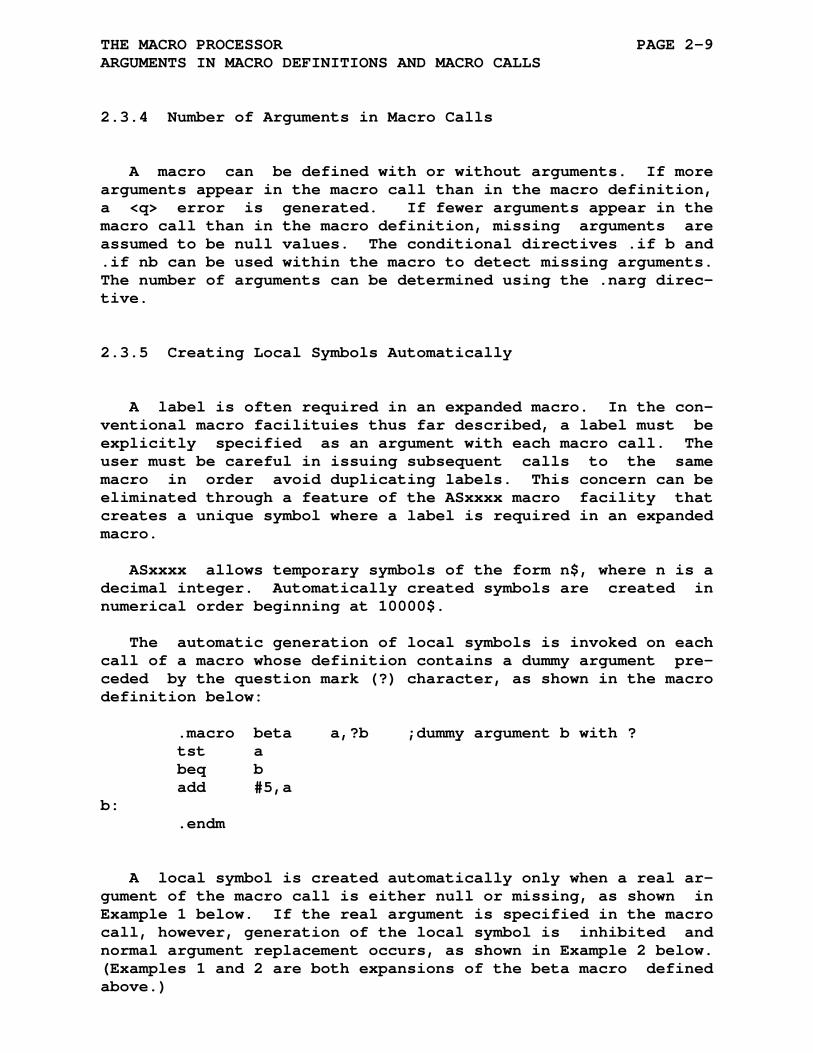
THE MACRO PROCESSOR PAGE 2-9 ARGUMENTS IN MACRO DEFINITIONS AND MACRO CALLS
2.3.4 Number of Arguments in Macro Calls
A macro can be defined with or without arguments. If more arguments appear in the macro call than in the macro definition, a <q> error is generated. If fewer arguments appear in the macro call than in the macro definition, missing arguments are assumed to be null values. The conditional directives .if b and .if nb can be used within the macro to detect missing arguments. The number of arguments can be determined using the .narg direc- tive.
2.3.5 Creating Local Symbols Automatically
A label is often required in an expanded macro. In the con- ventional macro facilituies thus far described, a label must be explicitly specified as an argument with each macro call. The user must be careful in issuing subsequent calls to the same macro in order avoid duplicating labels. This concern can be eliminated through a feature of the ASxxxx macro facility that creates a unique symbol where a label is required in an expanded macro.
ASxxxx allows temporary symbols of the form n$, where n is a decimal integer. Automatically created symbols are created in numerical order beginning at 10000$.
The automatic generation of local symbols is invoked on each call of a macro whose definition contains a dummy argument pre- ceded by the question mark (?) character, as shown in the macro definition below:
.macro beta a,?b ;dummy argument b with ? tst a beq b add #5,a b: .endm
A local symbol is created automatically only when a real ar- gument of the macro call is either null or missing, as shown in Example 1 below. If the real argument is specified in the macro call, however, generation of the local symbol is inhibited and normal argument replacement occurs, as shown in Example 2 below. (Examples 1 and 2 are both expansions of the beta macro defined above.)
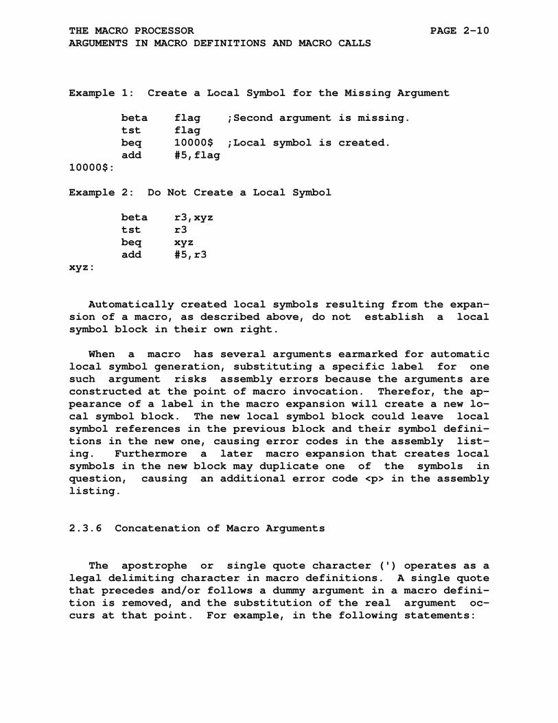
THE MACRO PROCESSOR PAGE 2-10 ARGUMENTS IN MACRO DEFINITIONS AND MACRO CALLS
Example 1: Create a Local Symbol for the Missing Argument beta flag ;Second argument is missing. tst flag beq 10000$ ;Local symbol is created. add #5,flag 10000$: Example 2: Do Not Create a Local Symbol beta r3,xyz tst r3 beq xyz add #5,r3 xyz:
Automatically created local symbols resulting from the expan- sion of a macro, as described above, do not establish a local symbol block in their own right.
When a macro has several arguments earmarked for automatic local symbol generation, substituting a specific label for one such argument risks assembly errors because the arguments are constructed at the point of macro invocation. Therefor, the ap- pearance of a label in the macro expansion will create a new lo- cal symbol block. The new local symbol block could leave local symbol references in the previous block and their symbol defini- tions in the new one, causing error codes in the assembly list- ing. Furthermore a later macro expansion that creates local symbols in the new block may duplicate one of the symbols in question, causing an additional error code <p> in the assembly listing.
2.3.6 Concatenation of Macro Arguments
The apostrophe or single quote character (') operates as a legal delimiting character in macro definitions. A single quote that precedes and/or follows a dummy argument in a macro defini- tion is removed, and the substitution of the real argument oc- curs at that point. For example, in the following statements:
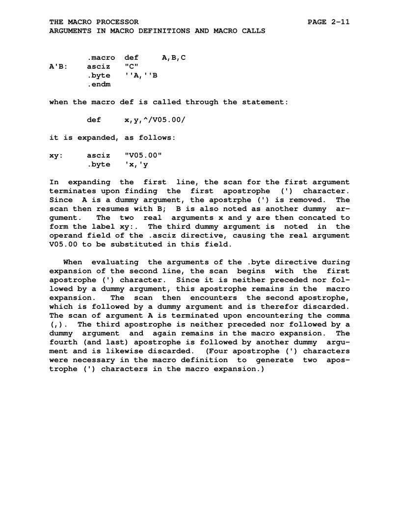
THE MACRO PROCESSOR PAGE 2-11 ARGUMENTS IN MACRO DEFINITIONS AND MACRO CALLS
.macro def A,B,C A'B: asciz "C" .byte ''A,''B .endm
when the macro def is called through the statement:
def x,y,^/V05.00/
it is expanded, as follows:
xy: asciz "V05.00" .byte 'x,'y
In expanding the first line, the scan for the first argument terminates upon finding the first apostrophe (') character. Since A is a dummy argument, the apostrphe (') is removed. The scan then resumes with B; B is also noted as another dummy ar- gument. The two real arguments x and y are then concated to form the label xy:. The third dummy argument is noted in the operand field of the .asciz directive, causing the real argument V05.00 to be substituted in this field.
When evaluating the arguments of the .byte directive during expansion of the second line, the scan begins with the first apostrophe (') character. Since it is neither preceded nor fol- lowed by a dummy argument, this apostrophe remains in the macro expansion. The scan then encounters the second apostrophe, which is followed by a dummy argument and is therefor discarded. The scan of argument A is terminated upon encountering the comma (,). The third apostrophe is neither preceded nor followed by a dummy argument and again remains in the macro expansion. The fourth (and last) apostrophe is followed by another dummy argu- ment and is likewise discarded. (Four apostrophe (') characters were necessary in the macro definition to generate two apos- trophe (') characters in the macro expansion.)
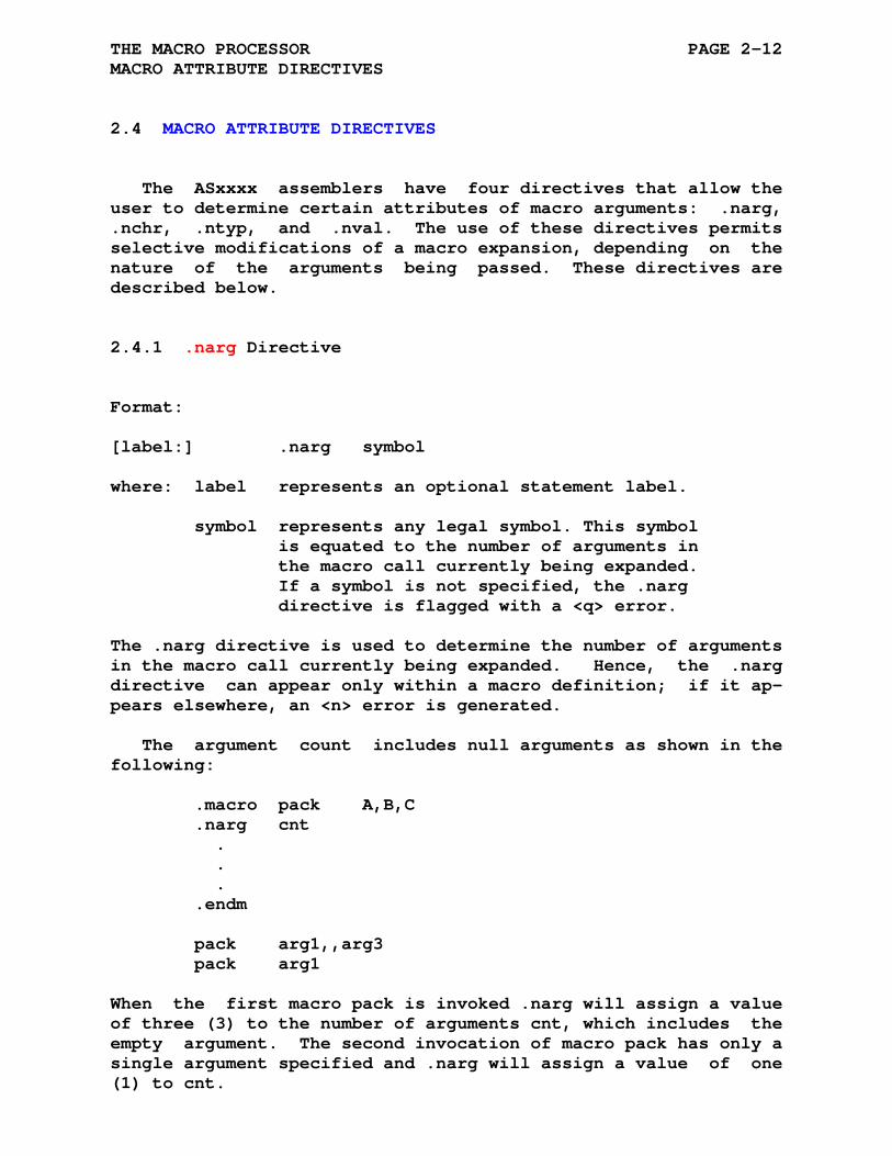
THE MACRO PROCESSOR PAGE 2-12 MACRO ATTRIBUTE DIRECTIVES
2.4 MACRO ATTRIBUTE DIRECTIVES
The ASxxxx assemblers have four directives that allow the user to determine certain attributes of macro arguments: .narg, .nchr, .ntyp, and .nval. The use of these directives permits selective modifications of a macro expansion, depending on the nature of the arguments being passed. These directives are described below.
2.4.1 .narg Directive
Format: [label:] .narg symbol where: label represents an optional statement label. symbol represents any legal symbol. This symbol is equated to the number of arguments in the macro call currently being expanded. If a symbol is not specified, the .narg directive is flagged with a <q> error.
The .narg directive is used to determine the number of arguments in the macro call currently being expanded. Hence, the .narg directive can appear only within a macro definition; if it ap- pears elsewhere, an <n> error is generated.
The argument count includes null arguments as shown in the following:
.macro pack A,B,C .narg cnt . . . .endm pack arg1,,arg3 pack arg1
When the first macro pack is invoked .narg will assign a value of three (3) to the number of arguments cnt, which includes the empty argument. The second invocation of macro pack has only a single argument specified and .narg will assign a value of one (1) to cnt.
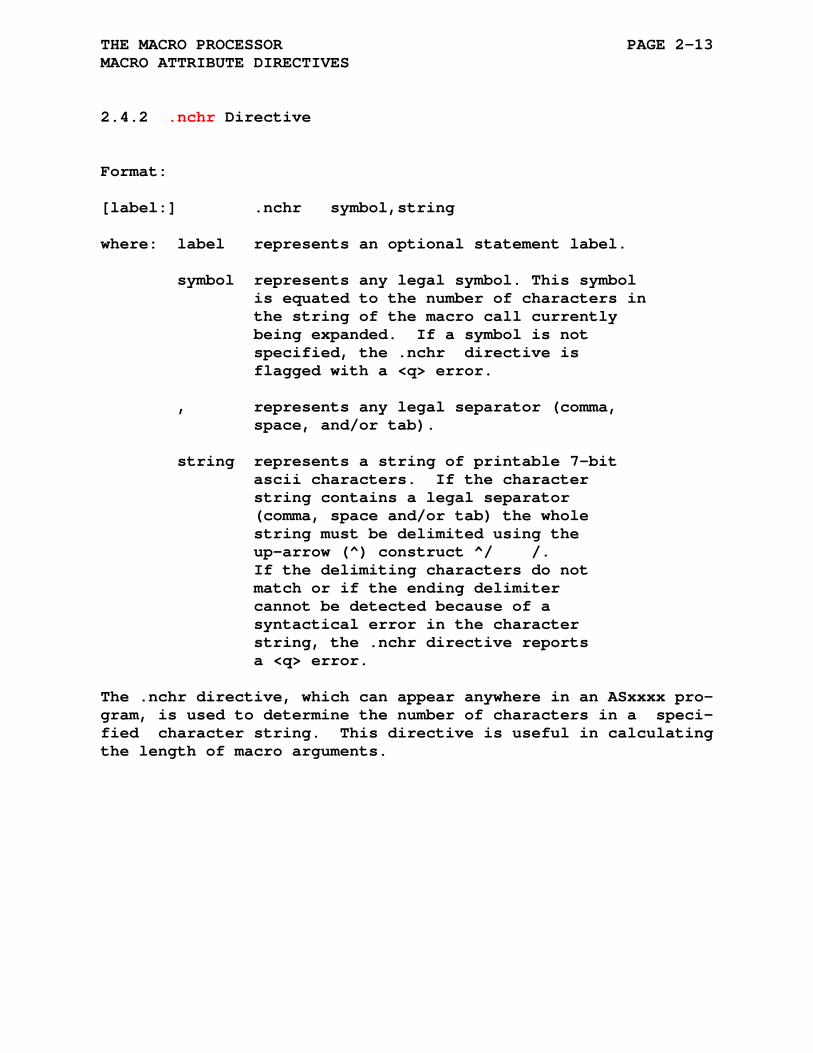
THE MACRO PROCESSOR PAGE 2-13 MACRO ATTRIBUTE DIRECTIVES
2.4.2 .nchr Directive
Format: [label:] .nchr symbol,string where: label represents an optional statement label. symbol represents any legal symbol. This symbol is equated to the number of characters in the string of the macro call currently being expanded. If a symbol is not specified, the .nchr directive is flagged with a <q> error. , represents any legal separator (comma, space, and/or tab). string represents a string of printable 7-bit ascii characters. If the character string contains a legal separator (comma, space and/or tab) the whole string must be delimited using the up-arrow (^) construct ^/ /. If the delimiting characters do not match or if the ending delimiter cannot be detected because of a syntactical error in the character string, the .nchr directive reports a <q> error.
The .nchr directive, which can appear anywhere in an ASxxxx pro- gram, is used to determine the number of characters in a speci- fied character string. This directive is useful in calculating the length of macro arguments.
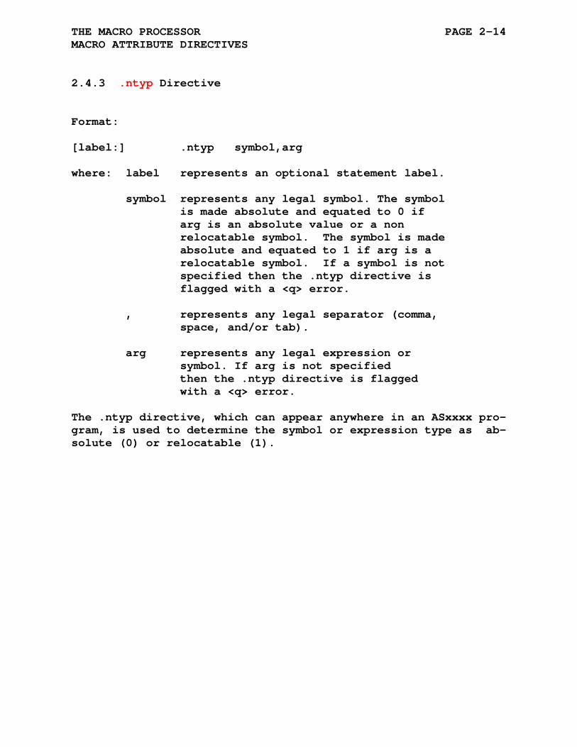
THE MACRO PROCESSOR PAGE 2-14 MACRO ATTRIBUTE DIRECTIVES
2.4.3 .ntyp Directive
Format: [label:] .ntyp symbol,arg where: label represents an optional statement label. symbol represents any legal symbol. The symbol is made absolute and equated to 0 if arg is an absolute value or a non relocatable symbol. The symbol is made absolute and equated to 1 if arg is a relocatable symbol. If a symbol is not specified then the .ntyp directive is flagged with a <q> error. , represents any legal separator (comma, space, and/or tab). arg represents any legal expression or symbol. If arg is not specified then the .ntyp directive is flagged with a <q> error.
The .ntyp directive, which can appear anywhere in an ASxxxx pro- gram, is used to determine the symbol or expression type as ab- solute (0) or relocatable (1).
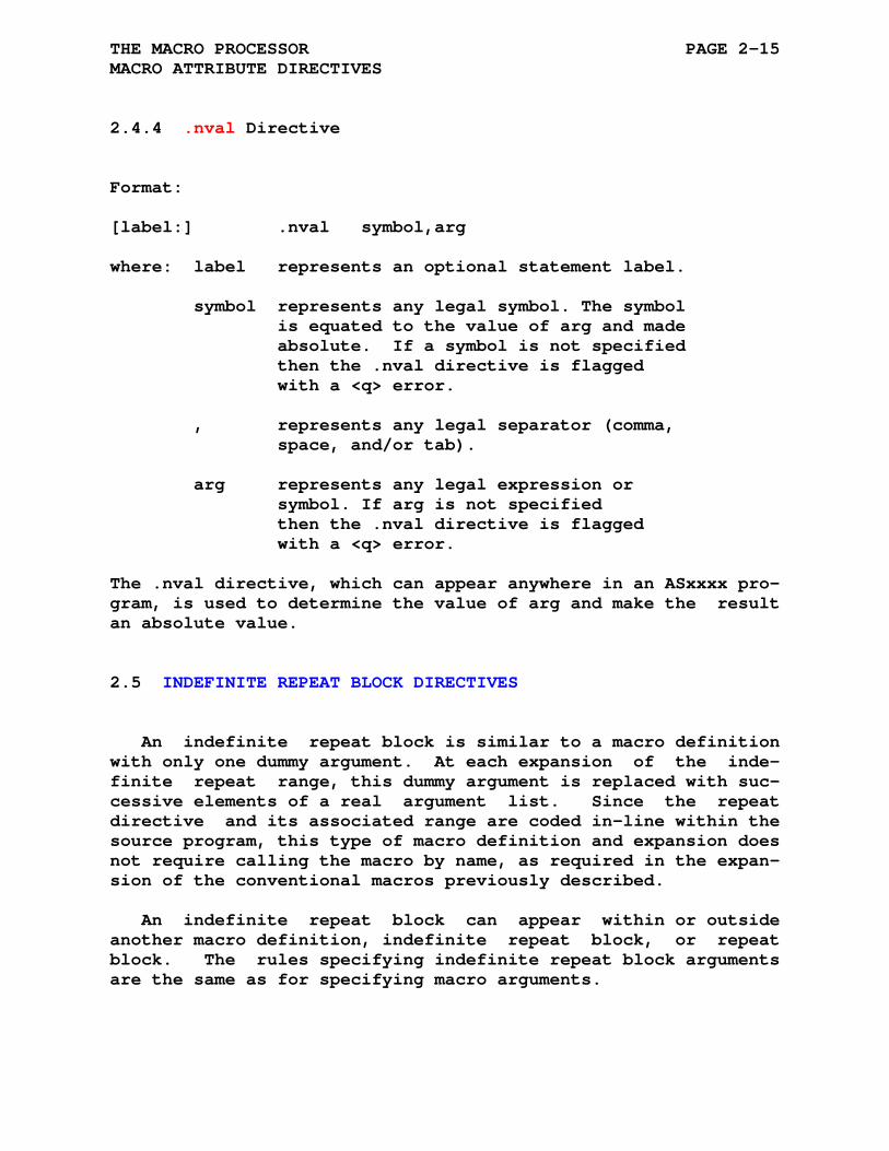
THE MACRO PROCESSOR PAGE 2-15 MACRO ATTRIBUTE DIRECTIVES
2.4.4 .nval Directive
Format: [label:] .nval symbol,arg where: label represents an optional statement label. symbol represents any legal symbol. The symbol is equated to the value of arg and made absolute. If a symbol is not specified then the .nval directive is flagged with a <q> error. , represents any legal separator (comma, space, and/or tab). arg represents any legal expression or symbol. If arg is not specified then the .nval directive is flagged with a <q> error.
The .nval directive, which can appear anywhere in an ASxxxx pro- gram, is used to determine the value of arg and make the result an absolute value.
2.5 INDEFINITE REPEAT BLOCK DIRECTIVES
An indefinite repeat block is similar to a macro definition with only one dummy argument. At each expansion of the inde- finite repeat range, this dummy argument is replaced with suc- cessive elements of a real argument list. Since the repeat directive and its associated range are coded in-line within the source program, this type of macro definition and expansion does not require calling the macro by name, as required in the expan- sion of the conventional macros previously described.
An indefinite repeat block can appear within or outside another macro definition, indefinite repeat block, or repeat block. The rules specifying indefinite repeat block arguments are the same as for specifying macro arguments.

THE MACRO PROCESSOR PAGE 2-16 INDEFINITE REPEAT BLOCK DIRECTIVES
2.5.1 .irp Directive
Format: [label:] .irp sym,argument_list . . (range of indefinite repeat block) . . .endm where: label represents an optional statement label. sym represents a dummy argument that is replaced with successive real arguments from the argument list. If the dummy argument is not specified, the .irp directive is flagged with a <q> error. , represents any legal separator (comma, space, and/or tab). argument_list represents a list of real arguments that are to be used in the expansion of the indefinite repeat range. A real argument may consist of one or more 7-bit ascii characters; multiple arguments must be separated by any legal separator (comma, space, and/or tab). If an argument must contain a legal separator then the up-arrow (_^) construct is require for that argument. If no real arguments are specified, no action is taken. range represents the block of code to be repeated once for each occurrence of a real argument in the list. The range may contain other macro definitions, repeat ranges and/or the .mexit directive. .endm indicates the end of the indefinite repeat block range.
The .irp directive is used to replace a dummy argument with suc- cessive real arguments specified in an argument list. This
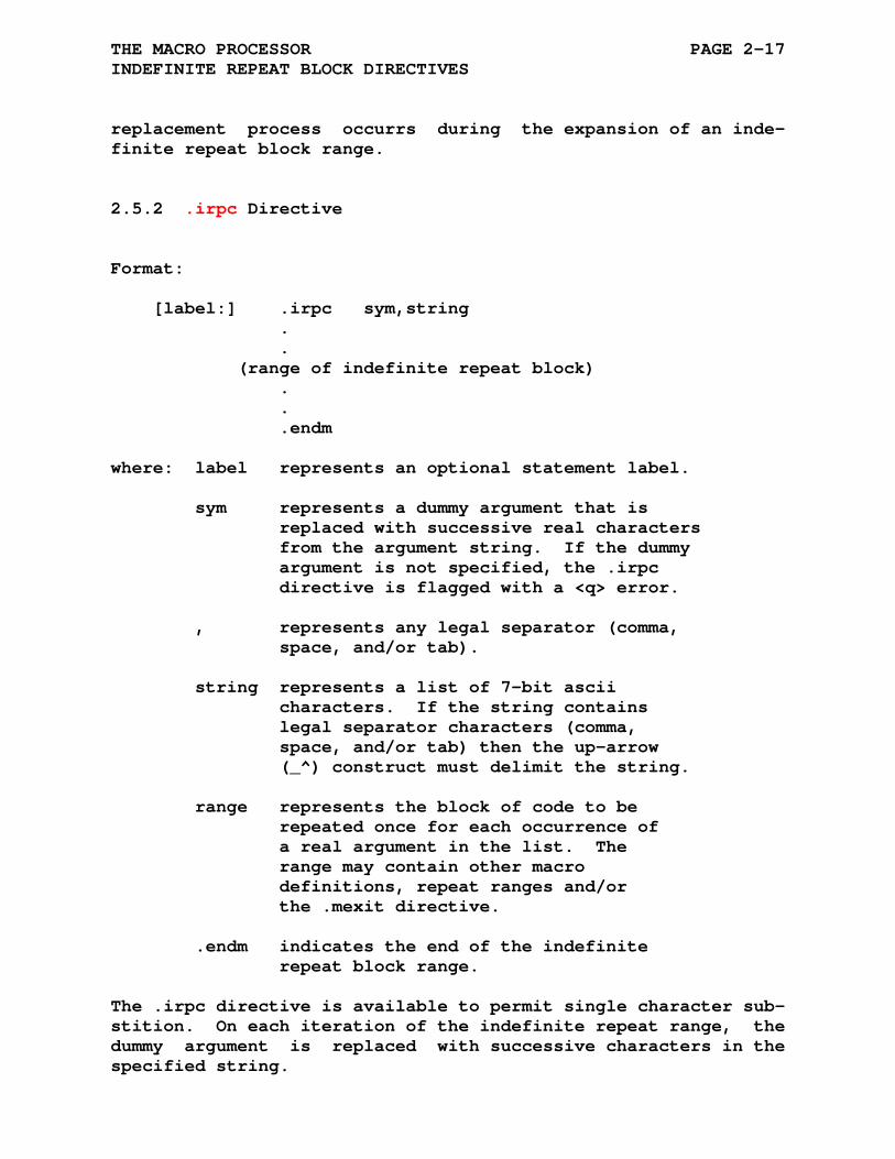
THE MACRO PROCESSOR PAGE 2-17 INDEFINITE REPEAT BLOCK DIRECTIVES
replacement process occurrs during the expansion of an inde- finite repeat block range.
2.5.2 .irpc Directive
Format: [label:] .irpc sym,string . . (range of indefinite repeat block) . . .endm where: label represents an optional statement label. sym represents a dummy argument that is replaced with successive real characters from the argument string. If the dummy argument is not specified, the .irpc directive is flagged with a <q> error. , represents any legal separator (comma, space, and/or tab). string represents a list of 7-bit ascii characters. If the string contains legal separator characters (comma, space, and/or tab) then the up-arrow (_^) construct must delimit the string. range represents the block of code to be repeated once for each occurrence of a real argument in the list. The range may contain other macro definitions, repeat ranges and/or the .mexit directive. .endm indicates the end of the indefinite repeat block range.
The .irpc directive is available to permit single character sub- stition. On each iteration of the indefinite repeat range, the dummy argument is replaced with successive characters in the specified string.

THE MACRO PROCESSOR PAGE 2-18 INDEFINITE REPEAT BLOCK DIRECTIVES
2.6 REPEAT BLOCK DIRECTIVE
A repeat block is similar to a macro definition with only one argument. The argument specifies the number of times the repeat block is inserted into the assembly stream. Since the repeat directive and its associated range are coded in-line within the source program, this type of macro definition and expansion does not require calling the macro by name, as required in the expan- sion of the conventional macros previously described.
A repeat block can appear within or outside another macro de- finition, indefinite repeat block, or repeat block.
2.6.1 .rept Directive
Format: [label:] .rept exp . . (range of repeat block) . . .endm where: label represents an optional statement label. exp represents any legal expression. This value controls the number of times the block of code is to be assembled within the program. When the expression value is less than or equal to zero (0), the repeat block is not assembled. If this value is not an absolute value, the .rept directive is flagged with an <r> error. range represents the block of code to be repeated. The range may contain other macro definitions, repeat ranges and/or the .mexit directive. .endm indicates the end of the repeat block range.
The .rept directive is used to duplicate a block of code, a

THE MACRO PROCESSOR PAGE 2-19 REPEAT BLOCK DIRECTIVE
certain number of times, in line with other source code.
2.7 MACRO DELETION DIRECTIVE
The .mdelete directive deletes the definitions of the the specified macro(s).
2.7.1 .mdelete Directive
Format: .mdelete name1,name2,...,namen where: name1, represent legal macro names. When multiple name2, names are specified, they are separated ..., by any legal separator (comma, space, and/or namen tab).
2.8 MACRO INVOCATION DETAILS
The invocation of a macro, indefinite repeat block, or repeat block has specific implications for .if-.else-.endif constructs and for .list-.nlist directives.
At the point a macro, indefinite repeat block, or repeat block is called the following occurs:
1) The initial .if-.else-.endif state is saved. 2) The initial .list-.nlist state is saved. 3) The macro, indefinite repeat block, or repeat block is inserted into the assembler source code stream. All argument substitution is performed at this point.
When the macro completes and after each pass through an inde- finite repeat block or repeat block the .if-.else-.endif and .list-.nlist state is reset to the initial state.
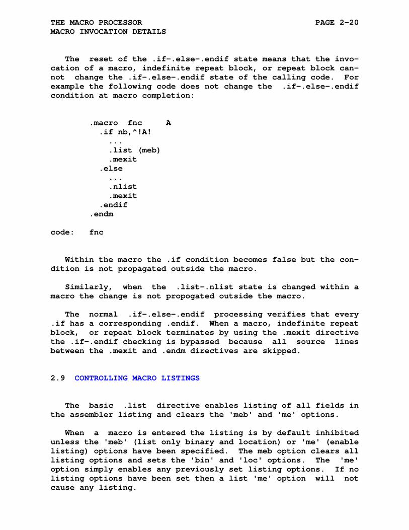
THE MACRO PROCESSOR PAGE 2-20 MACRO INVOCATION DETAILS
The reset of the .if-.else-.endif state means that the invo- cation of a macro, indefinite repeat block, or repeat block can- not change the .if-.else-.endif state of the calling code. For example the following code does not change the .if-.else-.endif condition at macro completion:
.macro fnc A .if nb,^!A! ... .list (meb) .mexit .else ... .nlist .mexit .endif .endm code: fnc
Within the macro the .if condition becomes false but the con- dition is not propagated outside the macro.
Similarly, when the .list-.nlist state is changed within a macro the change is not propogated outside the macro.
The normal .if-.else-.endif processing verifies that every .if has a corresponding .endif. When a macro, indefinite repeat block, or repeat block terminates by using the .mexit directive the .if-.endif checking is bypassed because all source lines between the .mexit and .endm directives are skipped.
2.9 CONTROLLING MACRO LISTINGS
The basic .list directive enables listing of all fields in the assembler listing and clears the 'meb' and 'me' options.
When a macro is entered the listing is by default inhibited unless the 'meb' (list only binary and location) or 'me' (enable listing) options have been specified. The meb option clears all listing options and sets the 'bin' and 'loc' options. The 'me' option simply enables any previously set listing options. If no listing options have been set then a list 'me' option will not cause any listing.

THE MACRO PROCESSOR PAGE 2-21 CONTROLLING MACRO LISTINGS
Within a macro the .list/.nlist directives can set or clear any of the listing options but listing will only occur when the 'me' option is set.
2.10 BUILDING A MACRO LIBRARY
Using the macro facilities of the ASxxxx assemblers a simple macro library can be built. The macro library is built by com- bining individual macros, sets of macros, or include file direc- tives into a single file. Each macro entity is enclosed within a .if/.endif block that selects the desired macro definitions.
The selection of specific macros to be imported in a program is performed by three macros, .mlib, .mcall, and .mload, con- tained in the file mlib.def.
2.10.1 .mlib Macro Directive
Format: .mlib file where: file represents the macro library file name. If the file name does not include a path then the path of the current assembly file is used. If the file name (and/or path) contains white space then the path/name must be delimited with the up-arrow (^) construct ^/ /.
The .mlib directive defines two macros, .mcall and .mload, which when invoked will read a file, importing specific macro defini- tions. Any previous .mcall and/or .mload directives will be deleted before the new .mcall and .mload directives are defined.
The .mload directive is an internal directive which simply includes the macro library file with the listing disabled.
The following is the mlib.def file which defines the macros .mlib, .mcall, and .mload.
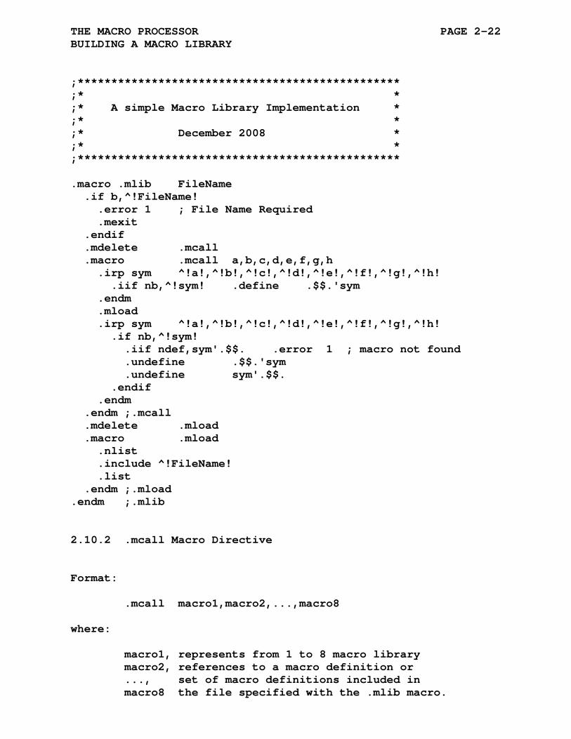
THE MACRO PROCESSOR PAGE 2-22 BUILDING A MACRO LIBRARY
;************************************************ ;* * ;* A simple Macro Library Implementation * ;* * ;* December 2008 * ;* * ;************************************************ .macro .mlib FileName .if b,^!FileName! .error 1 ; File Name Required .mexit .endif .mdelete .mcall .macro .mcall a,b,c,d,e,f,g,h .irp sym ^!a!,^!b!,^!c!,^!d!,^!e!,^!f!,^!g!,^!h! .iif nb,^!sym! .define .$$.'sym .endm .mload .irp sym ^!a!,^!b!,^!c!,^!d!,^!e!,^!f!,^!g!,^!h! .if nb,^!sym! .iif ndef,sym'.$$. .error 1 ; macro not found .undefine .$$.'sym .undefine sym'.$$. .endif .endm .endm ;.mcall .mdelete .mload .macro .mload .nlist .include ^!FileName! .list .endm ;.mload .endm ;.mlib
2.10.2 .mcall Macro Directive
Format: .mcall macro1,macro2,...,macro8 where: macro1, represents from 1 to 8 macro library macro2, references to a macro definition or ..., set of macro definitions included in macro8 the file specified with the .mlib macro.

THE MACRO PROCESSOR PAGE 2-23 BUILDING A MACRO LIBRARY
As can be seen from the macro definition of .mlib and .mcall shown above, when .mcall is invoked temporary symbols are de- fined for each macro or macro set that is to be imported. The macro .mload is then invoked to load the macro library file specified in the call to .mlib.
For example, when the following macros are invoked:
.mlib crossasm.sml ; Cross Assembler Macros .mcall M6809 ; M6809 Macro Group
The .mlib macro defines the .mload macro to access the system macro file crossasm.sml. Invoking the .mcall macro creates a temporary symbol, '.$$.M6809', and then invokes the macro .mload to import the system macro file crossasm.sml. The file cros- sasm.sml contains conditional statements that define the re- quired macros and creates a temporary symbol 'M6809.$$.' to indicate the macro group was found. If the macro is not found an error message is generated.
The following is a small portion of the crossasm.sml system macro file which shows the M6809 macro group:
.title Cross Assembler Macro Library ; This MACRO Library is Case Insensitive. ; ... ; Macro Based 6809 Cross Assembler .$.SML.$. =: 0 .if idn a,A .iif def,.$$.m6809 .$.SML.$. = -1 .else .iif def,.$$.m6809 .$.SML.$. = -1 .iif def,.$$.M6809 .$.SML.$. = 1 .endif .iif lt,.$.SML.$. .define m6809.$$. .iif gt,.$.SML.$. .define M6809.$$. .iif ne,.$.SML.$. .include "m6809.mac" ...
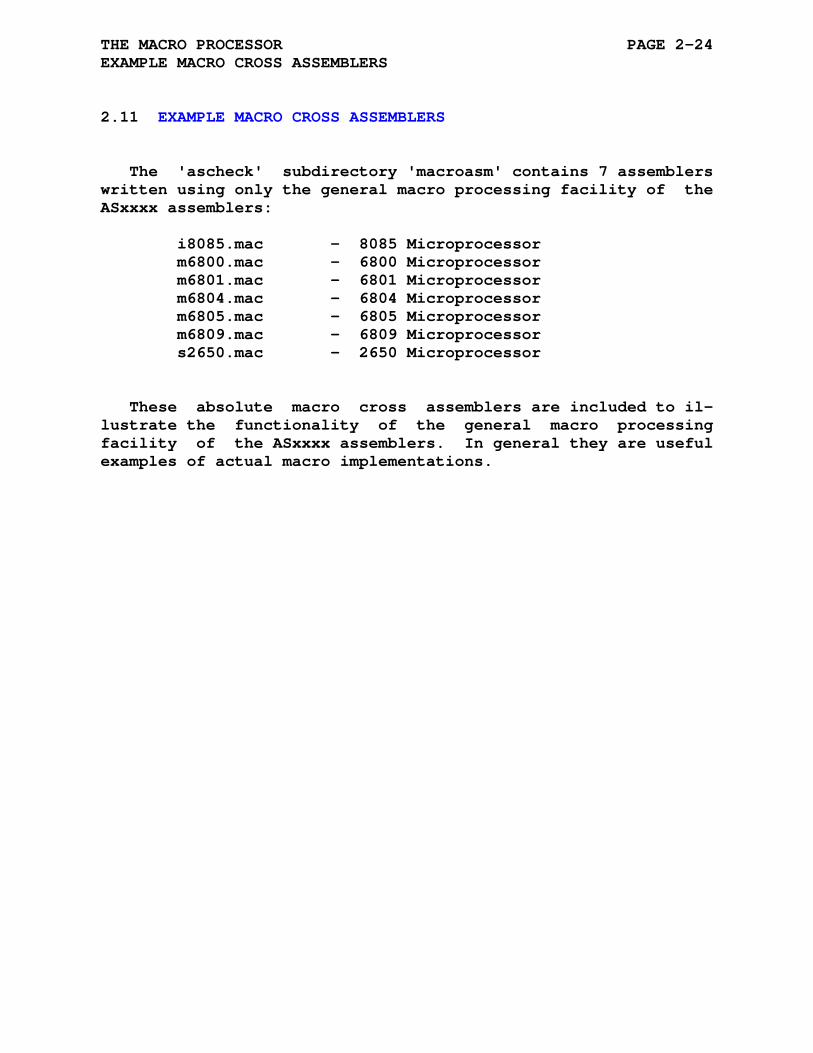
THE MACRO PROCESSOR PAGE 2-24 EXAMPLE MACRO CROSS ASSEMBLERS
2.11 EXAMPLE MACRO CROSS ASSEMBLERS
The 'ascheck' subdirectory 'macroasm' contains 7 assemblers written using only the general macro processing facility of the ASxxxx assemblers:
i8085.mac - 8085 Microprocessor m6800.mac - 6800 Microprocessor m6801.mac - 6801 Microprocessor m6804.mac - 6804 Microprocessor m6805.mac - 6805 Microprocessor m6809.mac - 6809 Microprocessor s2650.mac - 2650 Microprocessor
These absolute macro cross assemblers are included to il- lustrate the functionality of the general macro processing facility of the ASxxxx assemblers. In general they are useful examples of actual macro implementations.
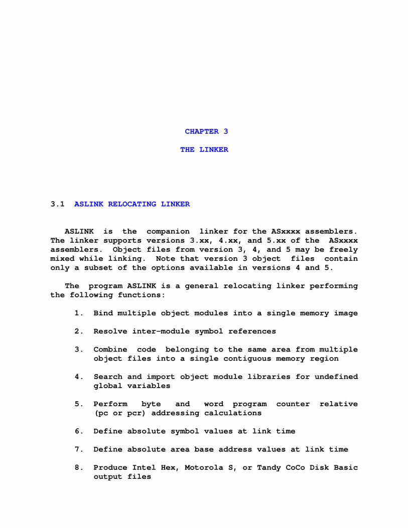
CHAPTER 3
THE LINKER
3.1 ASLINK RELOCATING LINKER
ASLINK is the companion linker for the ASxxxx assemblers. The linker supports versions 3.xx, 4.xx, and 5.xx of the ASxxxx assemblers. Object files from version 3, 4, and 5 may be freely mixed while linking. Note that version 3 object files contain only a subset of the options available in versions 4 and 5.
The program ASLINK is a general relocating linker performing the following functions:
1. Bind multiple object modules into a single memory image
2. Resolve inter-module symbol references
3. Combine code belonging to the same area from multiple object files into a single contiguous memory region
4. Search and import object module libraries for undefined global variables
5. Perform byte and word program counter relative (pc or pcr) addressing calculations
6. Define absolute symbol values at link time
7. Define absolute area base address values at link time
8. Produce Intel Hex, Motorola S, or Tandy CoCo Disk Basic output files
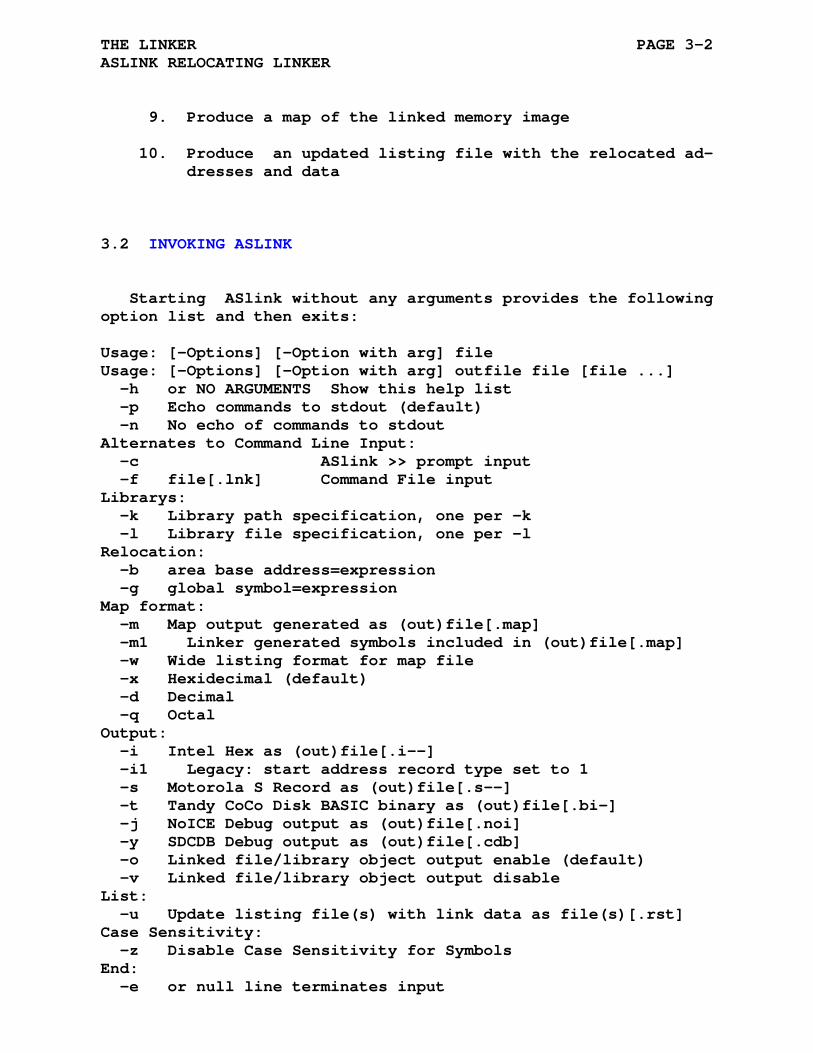
THE LINKER PAGE 3-2 ASLINK RELOCATING LINKER
9. Produce a map of the linked memory image
10. Produce an updated listing file with the relocated ad- dresses and data
3.2 INVOKING ASLINK
Starting ASlink without any arguments provides the following option list and then exits:
Usage: [-Options] [-Option with arg] file Usage: [-Options] [-Option with arg] outfile file [file ...] -h or NO ARGUMENTS Show this help list -p Echo commands to stdout (default) -n No echo of commands to stdout Alternates to Command Line Input: -c ASlink >> prompt input -f file[.lnk] Command File input Librarys: -k Library path specification, one per -k -l Library file specification, one per -l Relocation: -b area base address=expression -g global symbol=expression Map format: -m Map output generated as (out)file[.map] -m1 Linker generated symbols included in (out)file[.map] -w Wide listing format for map file -x Hexidecimal (default) -d Decimal -q Octal Output: -i Intel Hex as (out)file[.i--] -i1 Legacy: start address record type set to 1 -s Motorola S Record as (out)file[.s--] -t Tandy CoCo Disk BASIC binary as (out)file[.bi-] -j NoICE Debug output as (out)file[.noi] -y SDCDB Debug output as (out)file[.cdb] -o Linked file/library object output enable (default) -v Linked file/library object output disable List: -u Update listing file(s) with link data as file(s)[.rst] Case Sensitivity: -z Disable Case Sensitivity for Symbols End: -e or null line terminates input

THE LINKER PAGE 3-3 INVOKING ASLINK
NOTE
When ASlink is invoked with a single filename the created output file will have the same filename as the .rel file.
When ASlink is invoked with multiple filenames the first filename is the output filename and the remain- ing filenames are linked together into the output filename.
Most sytems require the options to be entered on the command line:
aslink [-Options] [-Options with args] file aslink [-Options] [-Options with args] outfile file1 [file2 ...]
Some systems may request the arguments after the linker is started at a system specific prompt:
aslink argv: -[options] -[options with args] file aslink argv: [-Options] [-Options with args] outfile file1 [file2 ...]
The linker commands are explained in some more detail:
1. -h or NO ARGUMENTS Show this help list Simply prints the help list on stdout.
2. -c ASlink >> prompt mode. The ASlink >> prompt mode reads linker commands from stdin.
3. -f file Command file mode. The command file mode imports linker commands from the specified file (extension must be .lnk), imported -c and -f commands are ignored. If the directory path,
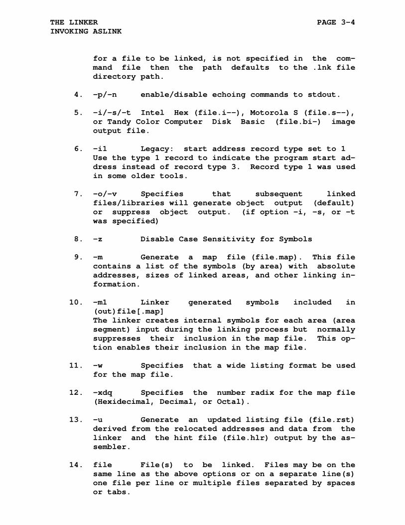
THE LINKER PAGE 3-4 INVOKING ASLINK
for a file to be linked, is not specified in the com- mand file then the path defaults to the .lnk file directory path.
4. -p/-n enable/disable echoing commands to stdout.
5. -i/-s/-t Intel Hex (file.i--), Motorola S (file.s--), or Tandy Color Computer Disk Basic (file.bi-) image output file.
6. -i1 Legacy: start address record type set to 1 Use the type 1 record to indicate the program start ad- dress instead of record type 3. Record type 1 was used in some older tools.
7. -o/-v Specifies that subsequent linked files/libraries will generate object output (default) or suppress object output. (if option -i, -s, or -t was specified)
8. -z Disable Case Sensitivity for Symbols
9. -m Generate a map file (file.map). This file contains a list of the symbols (by area) with absolute addresses, sizes of linked areas, and other linking in- formation.
10. -m1 Linker generated symbols included in (out)file[.map] The linker creates internal symbols for each area (area segment) input during the linking process but normally suppresses their inclusion in the map file. This op- tion enables their inclusion in the map file.
11. -w Specifies that a wide listing format be used for the map file.
12. -xdq Specifies the number radix for the map file (Hexidecimal, Decimal, or Octal).
13. -u Generate an updated listing file (file.rst) derived from the relocated addresses and data from the linker and the hint file (file.hlr) output by the as- sembler.
14. file File(s) to be linked. Files may be on the same line as the above options or on a separate line(s) one file per line or multiple files separated by spaces or tabs.
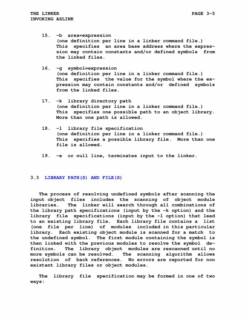
THE LINKER PAGE 3-5 INVOKING ASLINK
15. -b area=expression (one definition per line in a linker command file.) This specifies an area base address where the expres- sion may contain constants and/or defined symbols from the linked files.
16. -g symbol=expression (one definition per line in a linker command file.) This specifies the value for the symbol where the ex- pression may contain constants and/or defined symbols from the linked files.
17. -k library directory path (one definition per line in a linker command file.) This specifies one possible path to an object library. More than one path is allowed.
18. -l library file specification (one definition per line in a linker command file.) This specifies a possible library file. More than one file is allowed.
19. -e or null line, terminates input to the linker.
3.3 LIBRARY PATH(S) AND FILE(S)
The process of resolving undefined symbols after scanning the input object files includes the scanning of object module libraries. The linker will search through all combinations of the library path specifications (input by the -k option) and the library file specifications (input by the -l option) that lead to an existing library file. Each library file contains a list (one file per line) of modules included in this particular library. Each existing object module is scanned for a match to the undefined symbol. The first module containing the symbol is then linked with the previous modules to resolve the symbol de- finition. The library object modules are rescanned until no more symbols can be resolved. The scanning algorithm allows resolution of back references. No errors are reported for non existant library files or object modules.
The library file specification may be formed in one of two ways:
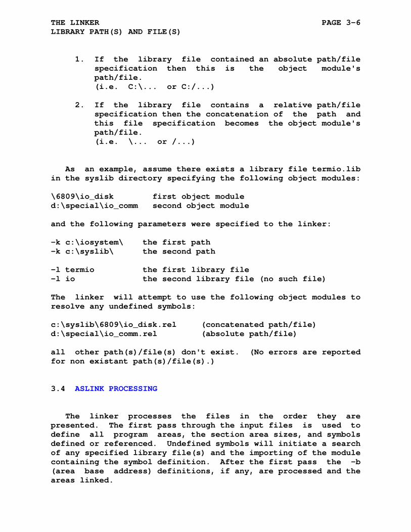
THE LINKER PAGE 3-6 LIBRARY PATH(S) AND FILE(S)
1. If the library file contained an absolute path/file specification then this is the object module's path/file. (i.e. C:\... or C:/...)
2. If the library file contains a relative path/file specification then the concatenation of the path and this file specification becomes the object module's path/file. (i.e. \... or /...)
As an example, assume there exists a library file termio.lib in the syslib directory specifying the following object modules:
\6809\io_disk first object module d:\special\io_comm second object module
and the following parameters were specified to the linker:
-k c:\iosystem\ the first path -k c:\syslib\ the second path
-l termio the first library file -l io the second library file (no such file)
The linker will attempt to use the following object modules to resolve any undefined symbols:
c:\syslib\6809\io_disk.rel (concatenated path/file) d:\special\io_comm.rel (absolute path/file)
all other path(s)/file(s) don't exist. (No errors are reported for non existant path(s)/file(s).)
3.4 ASLINK PROCESSING
The linker processes the files in the order they are presented. The first pass through the input files is used to define all program areas, the section area sizes, and symbols defined or referenced. Undefined symbols will initiate a search of any specified library file(s) and the importing of the module containing the symbol definition. After the first pass the -b (area base address) definitions, if any, are processed and the areas linked.
THE LINKER PAGE 3-7 ASLINK PROCESSING
The area linking proceeds by first examining the area types ABS, CON, REL, OVR and PAG. Absolute areas (ABS) from separate object modules are always overlayed and have been assembled at a specific address, these are not normally relocated (if a -b com- mand is used on an absolute area the area will be relocated). Relative areas (normally defined as REL|CON) have a base address of 0x0000 as read from the object files, the -b command speci- fies the beginning address of the area. All subsequent relative areas will be concatenated with preceeding relative areas. Where specific ordering is desired, the first linker input file should have the area definitions in the desired order. At the completion of the area linking all area addresses and lengths have been determined. The areas of type PAG are verified to be on a 256 byte boundary and that the length does not exceed 256 bytes. Any errors are noted on stderr and in the map file.
The linker also automatically generates two symbols for each linked program area:
'a_<area>' The starting address of the area.
'l_<area>' The length of the area.
and two symbols for each area segment:
'm_<area>_n' The boundary modulus of the area segment.
's_<area>_n' The starting address of the area segment.
The appended '_n' signifies the area segment number within a linked area.
These symbols are in general only useful diagnostically and are not visible externally. However if the -m1 linker option is used these symbols will be output to the map file.
Next the global symbol definitions (-g option), if any, are processed. The symbol definitions have been delayed until this point because the absolute addresses of all internal symbols are known and can be used in the expression calculations.
Before continuing with the linking process the symbol table is scanned to determine if any symbols have been referenced but not defined. Undefined symbols are listed on the stderr device. if a .module directive was included in the assembled file the module making the reference to this undefined variable will be printed.
THE LINKER PAGE 3-8 ASLINK PROCESSING
Constants defined as global in more than one module will be flagged as multiple definitions if their values are not identi- cal.
After the preceeding processes are complete the linker may output a map file (-m option). This file provides the following information:
1. Global symbol values and label absolute addresses
2. Defined areas and there lengths
3. Remaining undefined symbols
4. List of modules linked
5. List of library modules linked
6. List of -b and -g definitions
The final step of the linking process is performed during the second pass of the input files. As the xxx.rel files are read the code is relocated by substituting the physical addresses for the referenced symbols and areas and may be output in Intel, Motorola, or Tandy CoCo Disk Basic formats. The number of files linked and symbols defined/referenced is limited by the proces- sor space available to build the area/symbol lists. If the -u option is specified then the listing files (file.lst) associated with the relocation files (file.rel) are scanned and used to create a new file (file.rst) which has all addresses and data relocated to their final values.
The -o/-v options allow the simple creation of loadable or overlay modules. Loadable and overlay modules normally need to be linked with a main module(s) to resolve external symbols. The -o/-v options can be used to enable object output for the loadable or overlay module(s) and suppress the object code from the linked main module(s). The -o/-v options can be applied repeatedly to specify a single linked file, groups of files, or libraries for object code inclusion or suppression.

THE LINKER Page 3-9 ASXXXX VERSION 5.XX (4.XX) LINKING
3.5 ASXXXX VERSION 5.XX (4.XX) LINKING
The linkers' input object file is an ascii file containing the information needed by the linker to bind multiple object modules into a complete loadable memory image.
The object module contains the following designators:
[XDQ][HL][234] X Hexidecimal radix D Decimal radix Q Octal radix H Most significant byte first L Least significant byte first 2 16-Bit Addressing 3 24-Bit Addressing 4 32-Bit Addressing H Header M Module G Merge Mode B Bank A Area S Symbol T Object code R Relocation information P Paging information
3.5.1 Object Module Format
The first line of an object module contains the [XDQ][HL][234] format specifier (i.e. XH2 indicates a hex- idecimal file with most significant byte first and 16-bit ad- dressing) for the following designators.

THE LINKER PAGE 3-10 ASXXXX VERSION 5.XX (4.XX) LINKING
3.5.2 Header Line
H aa areas gg global symbols
The header line specifies the number of areas(aa) and the number of global symbols(gg) defined or referenced in this ob- ject module segment.
3.5.3 Module Line
M name
The module line specifies the module name from which this header segment was assembled. The module line will not appear if the .module directive was not used in the source program.
3.5.4 Merge Mode Line
G nn ii 00 01 02 03 04 05 06 07 08 09 0A 0B 0C 0D 0E 0F
The mode structure contains the specification (or partial specification) of one of the assemblers' merge modes. Sixteen bits may be specified on a single line. Each assembler must specify at least one merge mode. The merging specification al- lows arbitrarily defined active bits and bit positions. The 32 element arrays are indexed from 0 to 31. Index 0 corresponds to bit 0, ..., and 31 corresponds to bit 31 of a normal integer value.
1. nn is merge mode number
2. ii is the beginning bit position of the following data
3. 00 ... merge mode bit elements
The value of the element specifies if the normal in- teger bit is active (bit <7> is set, 0x80) and what destination bit (bits <4:0>, 0 - 31) should be loaded with this normal integer bit.
THE LINKER PAGE 3-11 ASXXXX VERSION 5.XX (4.XX) LINKING
3.5.5 Bank Line
B name base nn size nn map nn flags nn fsfx string
The B line defines a bank identifier as name. A bank is a structure containing a collection of areas. The bank is treated as a unique linking structure seperate from other banks. Each bank can have a unique base address (starting address). The size specification may be used to signal the overflow of the banks' allocated space. The Linker combines all areas included within a bank as seperate from other areas. The code from a bank may be output to a unique file by specifying the File Suf- fix parameter (fsfx). This allows the seperation of multiple data and code segments into isolated output files. The map parameter is for NOICE processing. The flags indicate if the parameters have been set.
3.5.6 Area Line
A label size ss flags ff [bank bb] [bndry mm]
The area line defines the area label, the size (ss) of the area in bytes, the area flags (ff), the optional [bank bb] specifies the bank this area is a member of, and the optional [bndry mm] which specifies the boundary modulus for this area segment. The area flags specify the ABS, REL, CON, OVR, and PAG parameters:
OVR/CON (0x04/0x00 i.e. bit position 2)
ABS/REL (0x08/0x00 i.e. bit position 3)
PAG (0x10 i.e. bit position 4)
The bank label is optional and only specified if the area is to be included within a bank.
When this area (area segment) is linked and their is a boun- dary modulus specified then the code/data beginning address will be increased to match the boundary modulus. This will also in- crease the area (area segment) size by the same amount.
THE LINKER PAGE 3-12 ASXXXX VERSION 5.XX (4.XX) LINKING
3.5.7 Symbol Line
S name Defnnnn
or
S name Refnnnn
The symbol line defines (Def) or references (Ref) the identi- fier name with the value nnnn. The defined value is relative to the current area base address. References to constants and ex- ternal global symbols will always appear before the first area definition. References to external symbols will have a value of zero.
3.5.8 T Line
T xx xx nn nn nn nn nn ...
The T line contains the assembled code output by the assem- bler with xx xx being the offset address from the current area base address and nn being the assembled instructions and data in byte format. (xx xx and nn nn can be 2, 3, or 4 bytes as speci- fied by the .REL file header.)
3.5.9 R Line
R 0 0 nn nn n1 n2 xx xx ...
The R line provides the relocation information to the linker. The nn nn value is the current area index, i.e. which area the current values were assembled. Relocation information is en- coded in groups of 4 bytes:
1. n1 is the relocation mode and object format. 1. bits <1:0> specify the number of bytes to output 2. bits <2:3> normal(0x00) / MSB (0x0C) signed(0x04) / unsigned(0x08) 3. bit 4 normal(0x00)/page '0' (0x10) reference 4. bit 5 normal(0x00)/page 'nnn' (0x20) reference PAGX mode if both bits are set (0x30) 5. bit 6 normal(0x00)/PC relative(0x40) relocation 6. bit 7 relocatable area(0x00)/symbol(0x80)
2. n2 is a byte index and a merge mode index
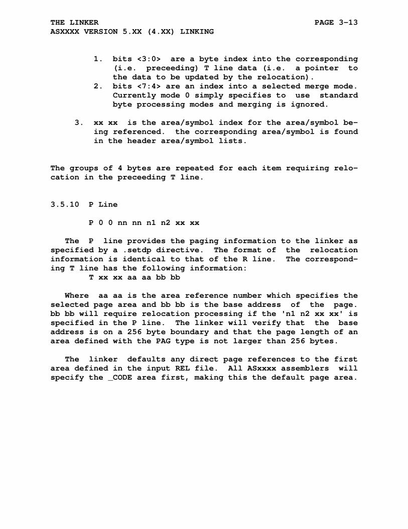
THE LINKER PAGE 3-13 ASXXXX VERSION 5.XX (4.XX) LINKING
1. bits <3:0> are a byte index into the corresponding (i.e. preceeding) T line data (i.e. a pointer to the data to be updated by the relocation). 2. bits <7:4> are an index into a selected merge mode. Currently mode 0 simply specifies to use standard byte processing modes and merging is ignored.
3. xx xx is the area/symbol index for the area/symbol be- ing referenced. the corresponding area/symbol is found in the header area/symbol lists.
The groups of 4 bytes are repeated for each item requiring relo- cation in the preceeding T line.
3.5.10 P Line
P 0 0 nn nn n1 n2 xx xx
The P line provides the paging information to the linker as specified by a .setdp directive. The format of the relocation information is identical to that of the R line. The correspond- ing T line has the following information: T xx xx aa aa bb bb
Where aa aa is the area reference number which specifies the selected page area and bb bb is the base address of the page. bb bb will require relocation processing if the 'n1 n2 xx xx' is specified in the P line. The linker will verify that the base address is on a 256 byte boundary and that the page length of an area defined with the PAG type is not larger than 256 bytes.
The linker defaults any direct page references to the first area defined in the input REL file. All ASxxxx assemblers will specify the _CODE area first, making this the default page area.
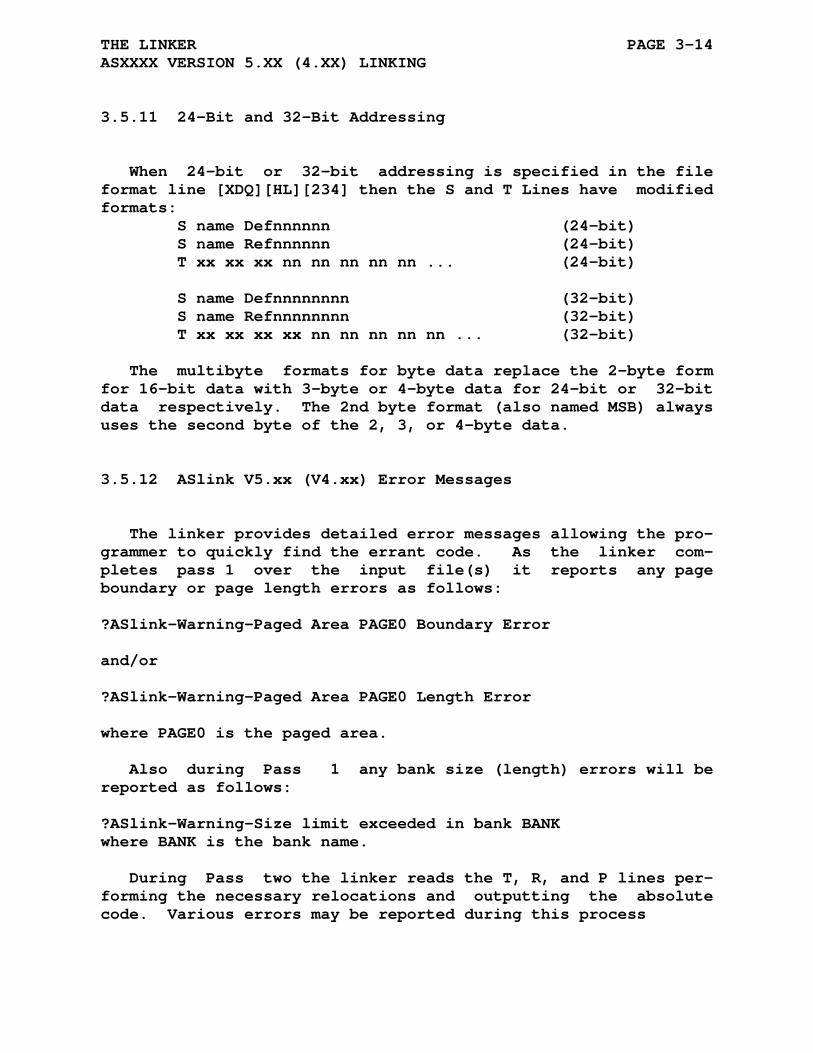
THE LINKER PAGE 3-14 ASXXXX VERSION 5.XX (4.XX) LINKING
3.5.11 24-Bit and 32-Bit Addressing
When 24-bit or 32-bit addressing is specified in the file format line [XDQ][HL][234] then the S and T Lines have modified formats: S name Defnnnnnn (24-bit) S name Refnnnnnn (24-bit) T xx xx xx nn nn nn nn nn ... (24-bit) S name Defnnnnnnnn (32-bit) S name Refnnnnnnnn (32-bit) T xx xx xx xx nn nn nn nn nn ... (32-bit)
The multibyte formats for byte data replace the 2-byte form for 16-bit data with 3-byte or 4-byte data for 24-bit or 32-bit data respectively. The 2nd byte format (also named MSB) always uses the second byte of the 2, 3, or 4-byte data.
3.5.12 ASlink V5.xx (V4.xx) Error Messages
The linker provides detailed error messages allowing the pro- grammer to quickly find the errant code. As the linker com- pletes pass 1 over the input file(s) it reports any page boundary or page length errors as follows:
?ASlink-Warning-Paged Area PAGE0 Boundary Error and/or ?ASlink-Warning-Paged Area PAGE0 Length Error
where PAGE0 is the paged area.
Also during Pass 1 any bank size (length) errors will be reported as follows:
?ASlink-Warning-Size limit exceeded in bank BANK where BANK is the bank name.
During Pass two the linker reads the T, R, and P lines per- forming the necessary relocations and outputting the absolute code. Various errors may be reported during this process
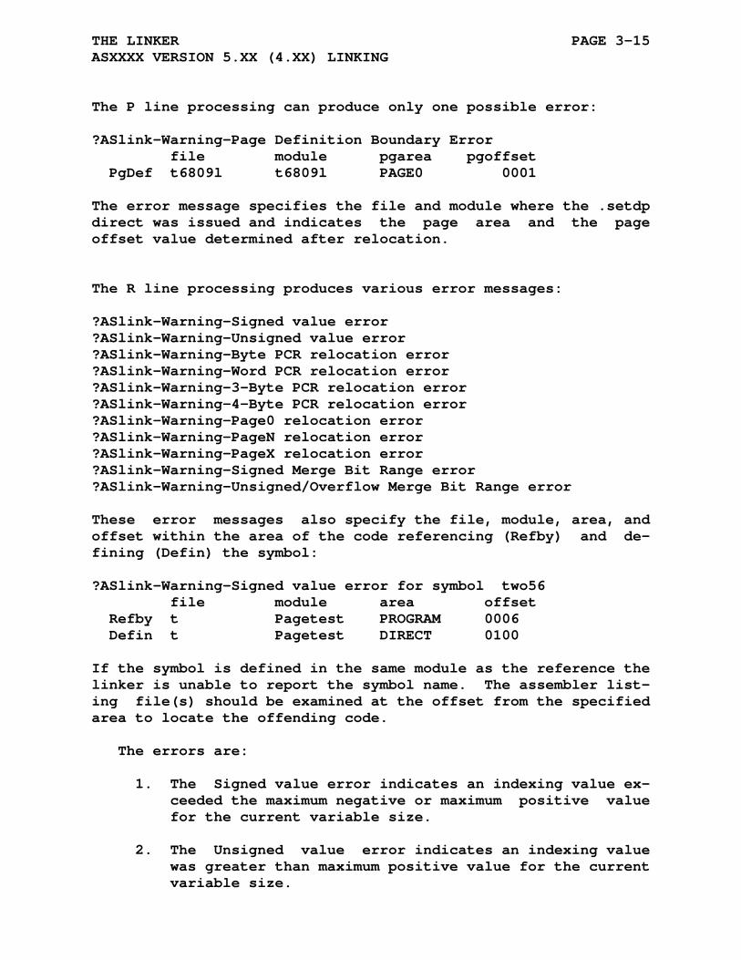
THE LINKER PAGE 3-15 ASXXXX VERSION 5.XX (4.XX) LINKING
The P line processing can produce only one possible error:
?ASlink-Warning-Page Definition Boundary Error file module pgarea pgoffset PgDef t6809l t6809l PAGE0 0001
The error message specifies the file and module where the .setdp direct was issued and indicates the page area and the page offset value determined after relocation.
The R line processing produces various error messages:
?ASlink-Warning-Signed value error ?ASlink-Warning-Unsigned value error ?ASlink-Warning-Byte PCR relocation error ?ASlink-Warning-Word PCR relocation error ?ASlink-Warning-3-Byte PCR relocation error ?ASlink-Warning-4-Byte PCR relocation error ?ASlink-Warning-Page0 relocation error ?ASlink-Warning-PageN relocation error ?ASlink-Warning-PageX relocation error ?ASlink-Warning-Signed Merge Bit Range error ?ASlink-Warning-Unsigned/Overflow Merge Bit Range error
These error messages also specify the file, module, area, and offset within the area of the code referencing (Refby) and de- fining (Defin) the symbol:
?ASlink-Warning-Signed value error for symbol two56 file module area offset Refby t Pagetest PROGRAM 0006 Defin t Pagetest DIRECT 0100
If the symbol is defined in the same module as the reference the linker is unable to report the symbol name. The assembler list- ing file(s) should be examined at the offset from the specified area to locate the offending code.
The errors are:
1. The Signed value error indicates an indexing value ex- ceeded the maximum negative or maximum positive value for the current variable size.
2. The Unsigned value error indicates an indexing value was greater than maximum positive value for the current variable size.

THE LINKER PAGE 3-16 ASXXXX VERSION 5.XX (4.XX) LINKING
3. The byte PCR error is caused by exceeding the pc rela- tive byte branch range.
4. The word PCR error is caused by exceeding the pc rela- tive word branch range.
5. The 3-byte PCR error is caused by exceeding the pc re- lative 3-byte branch range.
6. The 4-byte PCR error is caused by exceeding the pc re- lative 4-byte branch range.
7. The Page0 error is generated if the direct page vari- able is not in the page0 range of 0 to 255.
8. The PageN error is generated if the direct page vari- able is not within the Nth page range of 0 to 255.
9. The PageX error is generated if the direct page vari- able is not within the extended page range.
10. The Signed Merge Bit Range error indicates an indexing value exceeded the maximum negative or maximum positive value for the current signed merge variable size.
11. The Unsigned/Overflow Merge Bit Range error indicates an indexing value was greater than maximum positive value for the current unsigned merge variable size.

THE LINKER Page 3-17 ASXXXX VERSION 3.XX LINKING
3.6 ASXXXX VERSION 3.XX LINKING
The linkers' input object file is an ascii file containing the information needed by the linker to bind multiple object modules into a complete loadable memory image.
The object module contains the following designators:
[XDQ][HL][234] X Hexidecimal radix D Decimal radix Q Octal radix H Most significant byte first L Least significant byte first 2 16-Bit Addressing 3 24-Bit Addressing 4 32-Bit Addressing H Header M Module A Area S Symbol T Object code R Relocation information P Paging information
3.6.1 Object Module Format
The first line of an object module contains the [XDQ][HL][234] format specifier (i.e. XH2 indicates a hex- idecimal file with most significant byte first and 16-bit ad- dressing) for the following designators.
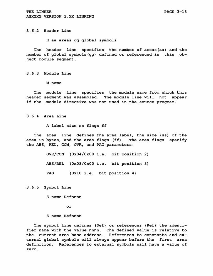
THE LINKER PAGE 3-18 ASXXXX VERSION 3.XX LINKING
3.6.2 Header Line
H aa areas gg global symbols
The header line specifies the number of areas(aa) and the number of global symbols(gg) defined or referenced in this ob- ject module segment.
3.6.3 Module Line
M name
The module line specifies the module name from which this header segment was assembled. The module line will not appear if the .module directive was not used in the source program.
3.6.4 Area Line
A label size ss flags ff
The area line defines the area label, the size (ss) of the area in bytes, and the area flags (ff). The area flags specify the ABS, REL, CON, OVR, and PAG parameters:
OVR/CON (0x04/0x00 i.e. bit position 2)
ABS/REL (0x08/0x00 i.e. bit position 3)
PAG (0x10 i.e. bit position 4)
3.6.5 Symbol Line
S name Defnnnn
or
S name Refnnnn
The symbol line defines (Def) or references (Ref) the identi- fier name with the value nnnn. The defined value is relative to the current area base address. References to constants and ex- ternal global symbols will always appear before the first area definition. References to external symbols will have a value of zero.
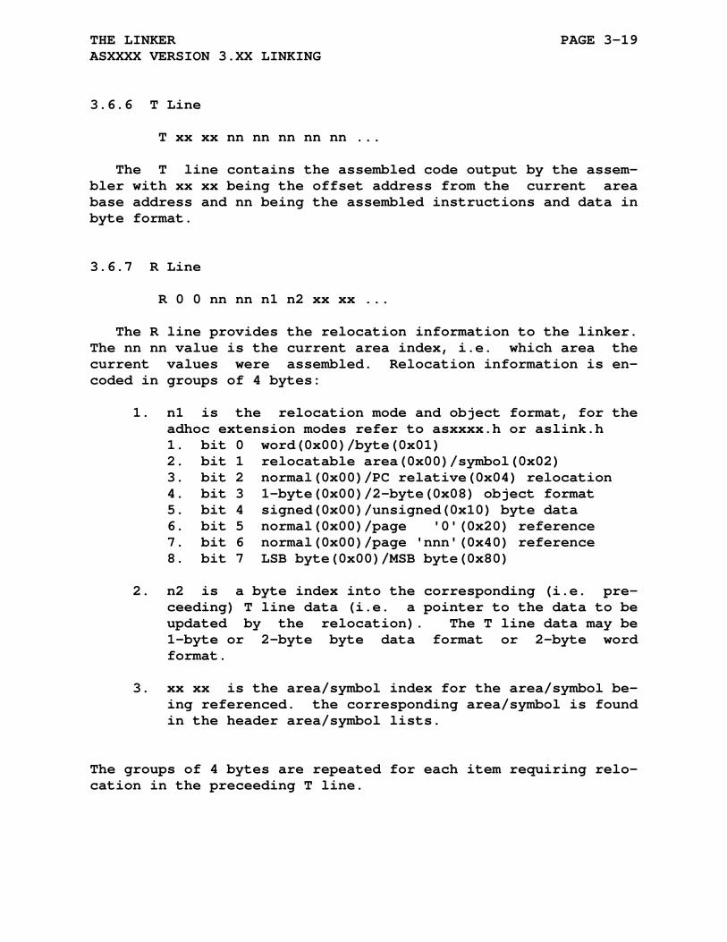
THE LINKER PAGE 3-19 ASXXXX VERSION 3.XX LINKING
3.6.6 T Line
T xx xx nn nn nn nn nn ...
The T line contains the assembled code output by the assem- bler with xx xx being the offset address from the current area base address and nn being the assembled instructions and data in byte format.
3.6.7 R Line
R 0 0 nn nn n1 n2 xx xx ...
The R line provides the relocation information to the linker. The nn nn value is the current area index, i.e. which area the current values were assembled. Relocation information is en- coded in groups of 4 bytes:
1. n1 is the relocation mode and object format, for the adhoc extension modes refer to asxxxx.h or aslink.h 1. bit 0 word(0x00)/byte(0x01) 2. bit 1 relocatable area(0x00)/symbol(0x02) 3. bit 2 normal(0x00)/PC relative(0x04) relocation 4. bit 3 1-byte(0x00)/2-byte(0x08) object format 5. bit 4 signed(0x00)/unsigned(0x10) byte data 6. bit 5 normal(0x00)/page '0'(0x20) reference 7. bit 6 normal(0x00)/page 'nnn'(0x40) reference 8. bit 7 LSB byte(0x00)/MSB byte(0x80)
2. n2 is a byte index into the corresponding (i.e. pre- ceeding) T line data (i.e. a pointer to the data to be updated by the relocation). The T line data may be 1-byte or 2-byte byte data format or 2-byte word format.
3. xx xx is the area/symbol index for the area/symbol be- ing referenced. the corresponding area/symbol is found in the header area/symbol lists.
The groups of 4 bytes are repeated for each item requiring relo- cation in the preceeding T line.

THE LINKER PAGE 3-20 ASXXXX VERSION 3.XX LINKING
3.6.8 P Line
P 0 0 nn nn n1 n2 xx xx
The P line provides the paging information to the linker as specified by a .setdp directive. The format of the relocation information is identical to that of the R line. The correspond- ing T line has the following information: T xx xx aa aa bb bb
Where aa aa is the area reference number which specifies the selected page area and bb bb is the base address of the page. bb bb will require relocation processing if the 'n1 n2 xx xx' is specified in the P line. The linker will verify that the base address is on a 256 byte boundary and that the page length of an area defined with the PAG type is not larger than 256 bytes.
The linker defaults any direct page references to the first area defined in the input REL file. All ASxxxx assemblers will specify the _CODE area first, making this the default page area.
3.6.9 24-Bit and 32-Bit Addressing
When 24-bit or 32-bit addressing is specified in the file format line [XDQ][HL][234] then the S and T Lines have modified formats: S name Defnnnnnn (24-bit) S name Refnnnnnn (24-bit) T xx xx xx nn nn nn nn nn ... (24-bit) S name Defnnnnnnnn (32-bit) S name Refnnnnnnnn (32-bit) T xx xx xx xx nn nn nn nn nn ... (32-bit)
The multibyte formats for byte data replace the 2-byte form for 16-bit data with 3-byte or 4-byte data for 24-bit or 32-bit data respectively. The 2nd byte format (also named MSB) always uses the second byte of the 2, 3, or 4-byte data.
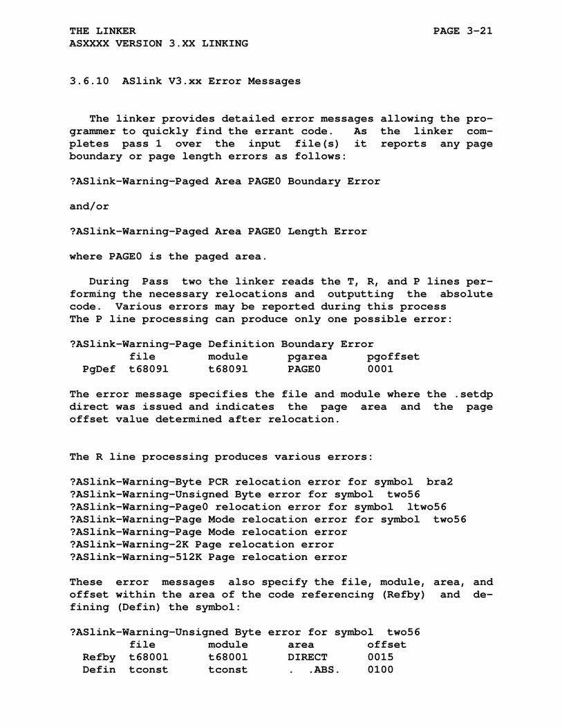
THE LINKER PAGE 3-21 ASXXXX VERSION 3.XX LINKING
3.6.10 ASlink V3.xx Error Messages
The linker provides detailed error messages allowing the pro- grammer to quickly find the errant code. As the linker com- pletes pass 1 over the input file(s) it reports any page boundary or page length errors as follows:
?ASlink-Warning-Paged Area PAGE0 Boundary Error and/or ?ASlink-Warning-Paged Area PAGE0 Length Error
where PAGE0 is the paged area.
During Pass two the linker reads the T, R, and P lines per- forming the necessary relocations and outputting the absolute code. Various errors may be reported during this process The P line processing can produce only one possible error:
?ASlink-Warning-Page Definition Boundary Error file module pgarea pgoffset PgDef t6809l t6809l PAGE0 0001
The error message specifies the file and module where the .setdp direct was issued and indicates the page area and the page offset value determined after relocation.
The R line processing produces various errors:
?ASlink-Warning-Byte PCR relocation error for symbol bra2 ?ASlink-Warning-Unsigned Byte error for symbol two56 ?ASlink-Warning-Page0 relocation error for symbol ltwo56 ?ASlink-Warning-Page Mode relocation error for symbol two56 ?ASlink-Warning-Page Mode relocation error ?ASlink-Warning-2K Page relocation error ?ASlink-Warning-512K Page relocation error
These error messages also specify the file, module, area, and offset within the area of the code referencing (Refby) and de- fining (Defin) the symbol:
?ASlink-Warning-Unsigned Byte error for symbol two56 file module area offset Refby t6800l t6800l DIRECT 0015 Defin tconst tconst . .ABS. 0100

THE LINKER PAGE 3-22 ASXXXX VERSION 3.XX LINKING
If the symbol is defined in the same module as the reference the linker is unable to report the symbol name. The assembler list- ing file(s) should be examined at the offset from the specified area to locate the offending code.
The errors are:
1. The byte PCR error is caused by exceeding the pc rela- tive byte branch range.
2. The Unsigned byte error indicates an indexing value was negative or larger than 255.
3. The Page0 error is generated if the direct page vari- able is not in the page0 range of 0 to 255.
4. The page mode error is generated if the direct variable is not within the current direct page (6809).
5. The 2K Page relocation error is generated if the destination is not within the current 2K page (8051, DS8xCxxx).
6. The 512K Page relocation error is generated if the destination is not within the current 512K page (DS80C390).

THE LINKER Page 3-23 HINT FILE FORMAT FOR RELOCATED LISTINGS
3.7 HINT FILE FORMAT FOR RELOCATED LISTINGS
The hint file is an ascii file containing information to help the linker convert the listing file into a relocated listing file. Each line in the .hlr file coresponds to a single line in the listing file. The text line usually contains 3 or 4 parame- ters in the radix selected for the assembler as shown in the following table:
Line Position: 123456789012 ------------ Octal: 111 222 333 Decimal: 111 222 333 Hex: 11 22 33 Parameter 1 specifies the parameters listed in the line. A bit is set for each listing option enabled during the assembly of the line. BIT 0 - LIST_ERR Error Code(s) BIT 1 - LIST_LOC Location BIT 2 - LIST_BIN Generated Binary Value(s) BIT 3 - LIST_EQT Assembler Equate Value BIT 4 - LIST_CYC Opcode Cycles BIT 5 - LIST_LIN Line Numbers BIT 6 - LIST_SRC Assembler Source Code BIT 7 - HLR_NLST Listing Inhibited Parameter 2 is the internal assembler listing mode value specified for this line during the assembly process: 0 - NLIST No listing 1 - SLIST Source only 2 - ALIST Address only 3 - BLIST Address only with allocation 4 - CLIST Code 5 - ELIST Equate only 6 - ILIST IF conditional evaluation Parameter 3 is the number of output bytes listed for this line.
The 4th parameter is only output if an equate references a value in a different area. The area name is output in the fol- lowing format following the 3 parameters described above:
Line Position: 123456789012 ------------
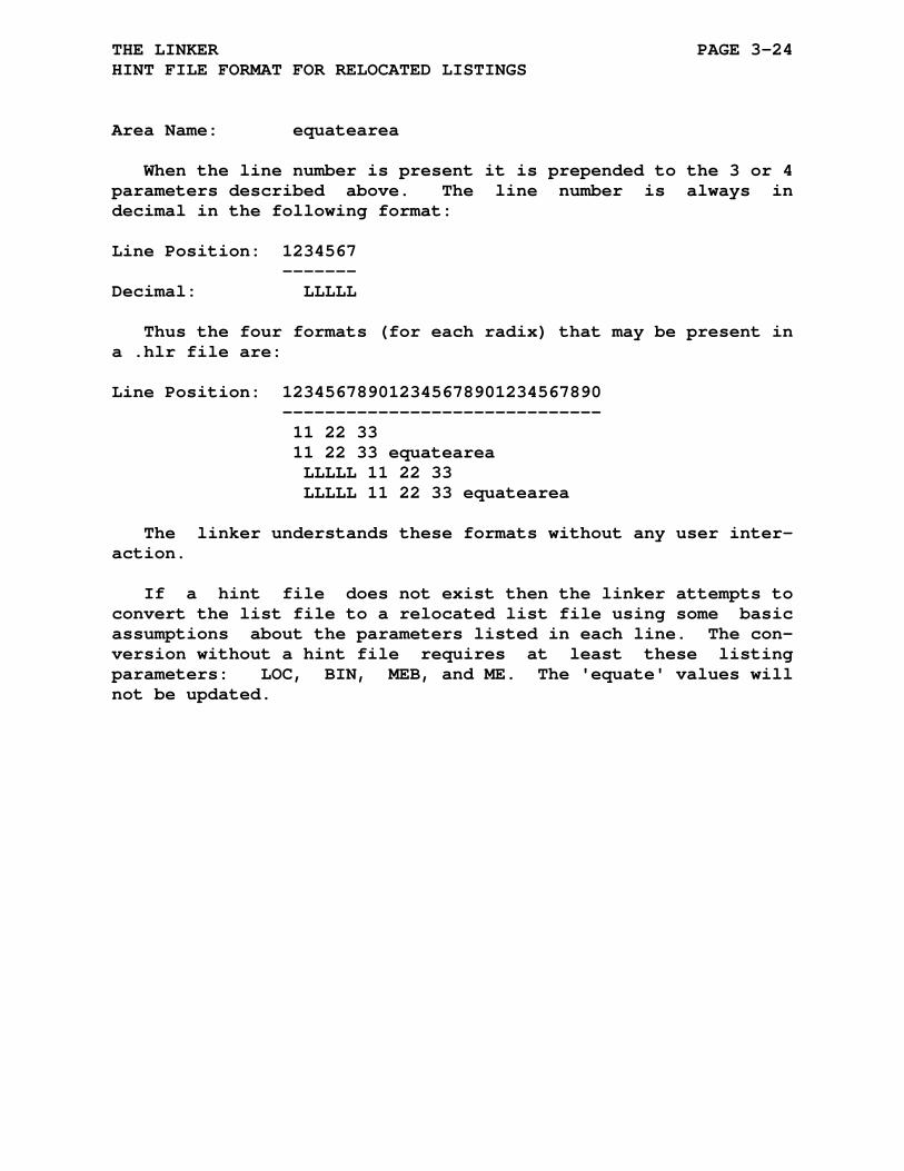
THE LINKER PAGE 3-24 HINT FILE FORMAT FOR RELOCATED LISTINGS
Area Name: equatearea
When the line number is present it is prepended to the 3 or 4 parameters described above. The line number is always in decimal in the following format:
Line Position: 1234567 ------- Decimal: LLLLL
Thus the four formats (for each radix) that may be present in a .hlr file are:
Line Position: 123456789012345678901234567890 ------------------------------ 11 22 33 11 22 33 equatearea LLLLL 11 22 33 LLLLL 11 22 33 equatearea
The linker understands these formats without any user inter- action.
If a hint file does not exist then the linker attempts to convert the list file to a relocated list file using some basic assumptions about the parameters listed in each line. The con- version without a hint file requires at least these listing parameters: LOC, BIN, MEB, and ME. The 'equate' values will not be updated.

THE LINKER Page 3-25 INTEL IHX OUTPUT FORMAT
3.8 INTEL IHX OUTPUT FORMAT (16-BIT)
Record Mark Field - This field signifies the start of a record, and consists of an ascii colon (:).
Record Length Field - This field consists of two ascii characters which indicate the number of data bytes in this record. The characters are the result of converting the number of bytes in binary to two ascii characters, high digit first. An End of File record contains two ascii zeros in this field.
Load Address Field - This field consists of the four ascii characters which result from converting the the binary value of the address in which to begin loading this record. The order is as follows:
High digit of high byte of address. Low digit of high byte of address. High digit of low byte of address. Low digit of low byte of address.
In an End of File record this field con- sists of either four ascii zeros or the program entry address.
Record Type Field - This field identifies the record type, which is either 0 for data, 1 for an End of File, or 3 for a start address record. It consists of two ascii characters, with the high digit of the record type first, followed by the low digit of the record type. The default start address record type is 3, however the -i1 option can override the default and use the type 1 record.
Data Field - This field consists of the actual data, converted to two ascii characters, high digit first. There are no data bytes in the End of File record.
Checksum Field - The checksum field is the 8 bit binary sum of the record length field, the load address field, the record type field,
THE LINKER PAGE 3-26 INTEL IHX OUTPUT FORMAT (16-BIT)
and the data field. This sum is then negated (2's complement) and converted to two ascii characters, high digit first.
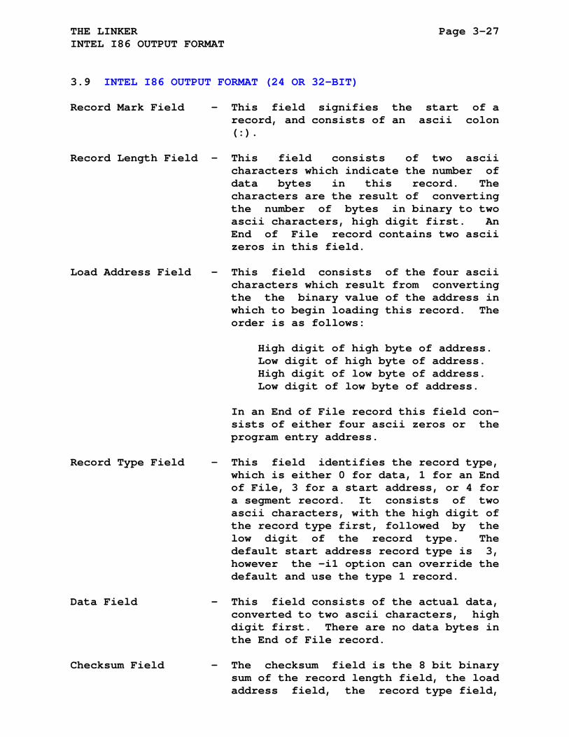
THE LINKER Page 3-27 INTEL I86 OUTPUT FORMAT
3.9 INTEL I86 OUTPUT FORMAT (24 OR 32-BIT)
Record Mark Field - This field signifies the start of a record, and consists of an ascii colon (:).
Record Length Field - This field consists of two ascii characters which indicate the number of data bytes in this record. The characters are the result of converting the number of bytes in binary to two ascii characters, high digit first. An End of File record contains two ascii zeros in this field.
Load Address Field - This field consists of the four ascii characters which result from converting the the binary value of the address in which to begin loading this record. The order is as follows:
High digit of high byte of address. Low digit of high byte of address. High digit of low byte of address. Low digit of low byte of address.
In an End of File record this field con- sists of either four ascii zeros or the program entry address.
Record Type Field - This field identifies the record type, which is either 0 for data, 1 for an End of File, 3 for a start address, or 4 for a segment record. It consists of two ascii characters, with the high digit of the record type first, followed by the low digit of the record type. The default start address record type is 3, however the -i1 option can override the default and use the type 1 record.
Data Field - This field consists of the actual data, converted to two ascii characters, high digit first. There are no data bytes in the End of File record.
Checksum Field - The checksum field is the 8 bit binary sum of the record length field, the load address field, the record type field,
THE LINKER PAGE 3-28 INTEL I86 OUTPUT FORMAT (24 OR 32-BIT)
and the data field. This sum is then negated (2's complement) and converted to two ascii characters, high digit first.
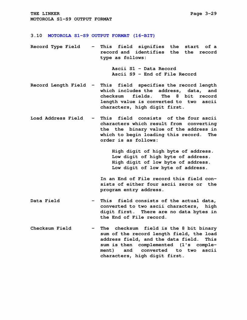
THE LINKER Page 3-29 MOTOROLA S1-S9 OUTPUT FORMAT
3.10 MOTOROLA S1-S9 OUTPUT FORMAT (16-BIT)
Record Type Field - This field signifies the start of a record and identifies the the record type as follows:
Ascii S1 - Data Record Ascii S9 - End of File Record
Record Length Field - This field specifies the record length which includes the address, data, and checksum fields. The 8 bit record length value is converted to two ascii characters, high digit first.
Load Address Field - This field consists of the four ascii characters which result from converting the the binary value of the address in which to begin loading this record. The order is as follows:
High digit of high byte of address. Low digit of high byte of address. High digit of low byte of address. Low digit of low byte of address.
In an End of File record this field con- sists of either four ascii zeros or the program entry address.
Data Field - This field consists of the actual data, converted to two ascii characters, high digit first. There are no data bytes in the End of File record.
Checksum Field - The checksum field is the 8 bit binary sum of the record length field, the load address field, and the data field. This sum is then complemented (1's comple- ment) and converted to two ascii characters, high digit first.
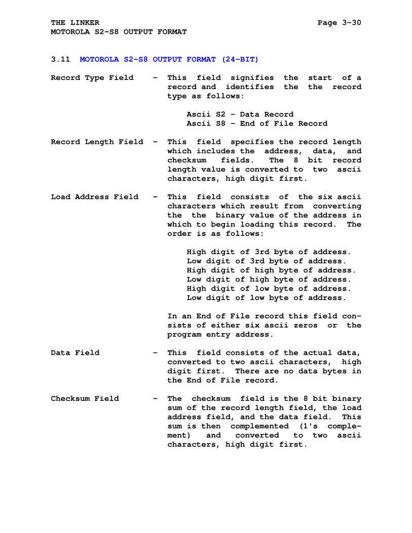
THE LINKER Page 3-30 MOTOROLA S2-S8 OUTPUT FORMAT
3.11 MOTOROLA S2-S8 OUTPUT FORMAT (24-BIT)
Record Type Field - This field signifies the start of a record and identifies the the record type as follows:
Ascii S2 - Data Record Ascii S8 - End of File Record
Record Length Field - This field specifies the record length which includes the address, data, and checksum fields. The 8 bit record length value is converted to two ascii characters, high digit first.
Load Address Field - This field consists of the six ascii characters which result from converting the the binary value of the address in which to begin loading this record. The order is as follows:
High digit of 3rd byte of address. Low digit of 3rd byte of address. High digit of high byte of address. Low digit of high byte of address. High digit of low byte of address. Low digit of low byte of address.
In an End of File record this field con- sists of either six ascii zeros or the program entry address.
Data Field - This field consists of the actual data, converted to two ascii characters, high digit first. There are no data bytes in the End of File record.
Checksum Field - The checksum field is the 8 bit binary sum of the record length field, the load address field, and the data field. This sum is then complemented (1's comple- ment) and converted to two ascii characters, high digit first.

THE LINKER Page 3-31 MOTOROLA S3-S7 OUTPUT FORMAT
3.12 MOTOROLA S3-S7 OUTPUT FORMAT (32-BIT)
Record Type Field - This field signifies the start of a record and identifies the the record type as follows:
Ascii S3 - Data Record Ascii S7 - End of File Record
Record Length Field - This field specifies the record length which includes the address, data, and checksum fields. The 8 bit record length value is converted to two ascii characters, high digit first.
Load Address Field - This field consists of the eight ascii characters which result from converting the the binary value of the address in which to begin loading this record. The order is as follows:
High digit of 4th byte of address. Low digit of 4th byte of address. High digit of 3rd byte of address. Low digit of 3rd byte of address. High digit of high byte of address. Low digit of high byte of address. High digit of low byte of address. Low digit of low byte of address.
In an End of File record this field con- sists of either eight ascii zeros or the program entry address.
Data Field - This field consists of the actual data, converted to two ascii characters, high digit first. There are no data bytes in the End of File record.
Checksum Field - The checksum field is the 8 bit binary sum of the record length field, the load address field, and the data field. This sum is then complemented (1's comple- ment) and converted to two ascii characters, high digit first.

THE LINKER Page 3-32 TANDY COLOR COMPUTER DISK BASIC BINARY FORMAT
3.13 TANDY COLOR COMPUTER DISK BASIC FORMAT
Record Preamble - This field is either $00 (for start of new record) or $FF (for last record in file).
Record Length Field - This field specifies the number of data bytes which follows the address field. The length is in binary MSB to LSB order.
16-Bit Length - 2-bytes 24-Bit Length - 3-bytes 32-Bit Length - 4-bytes
Load Address Field - This field consists of the address where the record will be loaded into memory. The address is in binary MSB to LSB order.
16-Bit Address - 2-bytes 24-Bit Address - 3-bytes 32-Bit Address - 4-bytes
Data Field - This field consists of the actual binary data.
After the last code segment, a final record like the one above is placed. In this final segment, the Record Preamble is $FF, the Record Length Field is $0000 and the Load Adress Field is the execution address.
CHAPTER 4
BUILDING ASXXXX AND ASLINK
The assemblers and linker have been successfully compiled for Linux, DOS, and various flavors of Windows using the Linux GCC, the Cygwin environment, the DJGPP environment, and the graphical user interfaces and command line environments of MS Visual C++ V6.0, MS Visual Studio 2005, 2010, 2013, 2015, Open Watcom V1.9, Symantec C/C++ V7.2, and Turbo C 3.0.
Makefiles for Linux, Cygwin, DJGPP, project files and a makefile for Turbo C and psuedo makefiles and project files for VC6, VS2005, VS2010, VS2013, VS2015, Open Watcom and Symantec are available to build all the assemblers and the linker.
Unpack the asxv5pxx.zip file into an appropriate directory using the utility appropriate to your environment. For DOS or Windows the following command line will unpack the distribution zip file:
pkunzip -d asxv5pxx.zip
The distribution file has been packed with DOS style end of lines (CR/LF), and UPPER CASE file names. The Linux make file assumes all lower case directories and file names. For Linux the unpacking utility you choose should have an option to force all lower case directories / file names and convert the ascii files to local format. On most systems the following command should do the trick:
unzip -L -a asxv5pxx.zip
Some systems may require a -LL option to force all lower case.
The distribution will be unpacked into the base directory 'asxv5pxx' which will contain source directories for each
BUILDING ASXXXX AND ASLINK Page 4-2
supported processor (as6800, asz80, ...), the machine indepen- dent source (asxxsrc), the linker source (linksrc), and the miscellaneous sources (asxxmisc). Other directories include the documentation (asxdoc), test file directory (asxtst), html do- cumentation (asxhtml), NoICE support files (noice), various debug monitors that can be assembled with the ASxxxx assemblers (asmasm), project files for an application that uses the AS6809 assembler and ASlink linker (project), and the packaging direc- tory (zipper).
4.1 BUILDING ASXXXX AND ASLINK WITH LINUX
The Linux build directory is /asxv5pxx/asxmak/linux/build. The makefile in this directory is compatible with the Linux GNU make and GCC. The command
make clean
will remove all the current executable files in directory /asxv5pxx/asxmak/linux/exe and all the compiled object modules from the /asxv5pxx/asxmak/linux/build directory.
The command
make all
will compile and link all the ASxxxx assemblers, the ASlink pro- gram, and the utility programs asxscn and asxcnv. The make file can make a single program by invoking make with the specific as- sembler, linker, or utility you wish to build:
make aslink
4.2 BUILDING ASXXXX AND ASLINK UNDER CYGWIN
The Cygwin build directory is \asxv5pxx\asxmak\cygwin\build. The makefile in this directory is compatible with the Cygwin GNU make and GCC. The command
make clean
will remove all the current executable files in directory \asxv5pxx\asxmak\cygwin\exe and all the compiled object modules from the \asxv5pxx\asxmak\cygwin\build directory. The command
BUILDING ASXXXX AND ASLINK PAGE 4-3 BUILDING ASXXXX AND ASLINK UNDER CYGWIN
make all
will compile and link all the ASxxxx assemblers, the ASlink pro- gram, and the utility programs asxscn and asxcnv. The make file can make a single program by invoking make with the specific as- sembler, linker, or utility you wish to build:
make aslink
4.3 BUILDING ASXXXX AND ASLINK WITH DJGPP
The DJGPP build directory is \asxv5pxx\asxmak\djgpp\build. The makefile in this directory is compatible with the DJGPP GNU make and GCC. The command
make clean
will remove all the current executable files in directory \asxv5pxx\asxmak\djgpp\exe and all the compiled object modules from the \asxv5pxx\asxmak\djgpp\build directory. The command
make all
will compile and link all the ASxxxx assemblers, the ASlink pro- gram, and the utility programs asxscn and asxcnv. The make file can make a single program by invoking make with the specific as- sembler, linker, or utility you wish to build:
make aslink
4.4 BUILDING ASXXXX AND ASLINK WITH BORLAND'S TURBO C++ 3.0
The Borland product is available in the Borland Turbo C++ Suite which contains C++ Builder 1.0, Turbo C++ 4.5 for Windows and Turbo C++ 3.0 for DOS. The DOS IDE will install and run on x86 (16 or 32 bit) versions of Windows (not x64 versions).

BUILDING ASXXXX AND ASLINK PAGE 4-4 BUILDING ASXXXX AND ASLINK WITH BORLAND'S TURBO C++ 3.0
4.4.1 Graphical User Interface
Each ASxxxx Assembler has two project specific files (*.dsk and *.prj) located in the subdirectory \asxv5pxx\asxmak\turboc30\build. You must enter the .prj filename into the Turbo C++ IDE: enter Options->Directories and change the include and output directories to match your confi- guration. After these changes have been made you will be able to compile the selected project. These changes must be manually entered for each project.
4.4.2 Command Line Interface
Before the command line interface can be used you must per- form the steps outlined in the 'Graphical User Interface' in- structions above for each project you wish to build.
Open a command prompt window in the \asxv5pxx\asxmak\turboc30\build directory. Assuming the Turbo C compiler has been installed in the default location (C:\TC) the file _setpath.bat will set the PATH variable. If this is not the case then the line
PATH=C:\TC;C:\TC\BIN;C:\TC\INCLUDE
must be changed to match your environment. The compiled object code modules will be placed in the \asxv5pxx\asxmak\turboc30\build\ directory and the executable files will be placed in the \asxv5pxx\asxmak\turboc30\exe direc- tory.
The command
make all
will compile and link all the ASxxxx assemblers, the ASlink pro- gram, and the utility programs asxscn and asxcnv. The make file can make a single program by invoking make with the specific as- sembler, linker, or utility you wish to build:
make aslink
The Turbo C make utility uses the information in the
BUILDING ASXXXX AND ASLINK PAGE 4-5 BUILDING ASXXXX AND ASLINK WITH BORLAND'S TURBO C++ 3.0
corresponding .prj and .dsk files to compile and link the pro- grams.
The file _makeall.bat found in the directory can also be used to invoke the Turbo C command line compiler. The _makeall.bat file calls the _setpath.bat file to set the path to the compiler directories in the environment variable PATH and then invokes 'make all'.
4.5 BUILDING ASXXXX AND ASLINK WITH MS VISUAL C++ 6.0
4.5.1 Graphical User Interface
Each ASxxxx Assembler has a VC6 project file (*.dsw) located in a subdirectory of \asxv5pxx\asxmak\vc6\build. Simply enter this project filename into the VC6 IDE and build/rebuild the as- sembler.
4.5.2 Command Line Interface
Open a command prompt window in the \asxv5pxx\asxmak\vc6\build directory. The file make.bat found in the directory can be used to invoke the VC6 command line com- piler. The make.bat file assumes that the Visual C++ compiler has been installed in the default location. If this is not the case then the line
SET MS$DEV="C:\Program Files\Microsoft Visual Studio\ Common\MSDev98\Bin\msdev.exe"
must be changed to match your environment. The compiled object code modules will be placed in the \asxv5pxx\asxmak\vc6\build\as----\release directory and the exe- cutable files will be placed in the \asxv5pxx\asxmak\vc6\exe directory.
The command
make all
will compile and link all the ASxxxx assemblers, the ASlink

BUILDING ASXXXX AND ASLINK PAGE 4-6 BUILDING ASXXXX AND ASLINK WITH MS VISUAL C++ 6.0
program, and the utility programs asxscn and asxcnv. The make file can make a single program by invoking make with the specific assembler, linker, or utility you wish to build:
make aslink
The VC6 command line compiler uses the information in the cor- responding .dsw/.dsp files to compile and link the programs.
The command 'make clean' is not required or valid as a make of anything does a complete rebuild of the program.
4.6 BUILDING ASXXXX AND ASLINK WITH MS VISUAL STUDIO 2005
4.6.1 Graphical User Interface
Each ASxxxx Assembler has a VS2005 project file (*.vcproj) located in a subdirectory of \asxv5pxx\asxmak\vs05\build. Sim- ply enter this project filename into the VS2005 IDE and build/rebuild the assembler.
4.6.2 Command Line Interface
Open a command prompt window in the \asxv5pxx\asxmak\vs05\build directory. The file make.bat found in the directory can be used to invoke the VS2005 command line compiler. The make.bat file assumes that the Visual C++ com- piler has been installed in the default location. If this is not the case then the line
SET VC$BUILD="C:\Program Files\Microsoft Visual Studio 8\ Common\MSDev98\Bin\msdev.exe"
must be changed to match your environment. The compiled object code modules will be placed in the \asxv5pxx\asxmak\vs05\build\as----\release directory and the ex- ecutable files will be placed in the \asxv5pxx\asxmak\vs05\exe directory.

BUILDING ASXXXX AND ASLINK PAGE 4-7 BUILDING ASXXXX AND ASLINK WITH MS VISUAL STUDIO 2005
The command
make all
will compile and link all the ASxxxx assemblers, the ASlink pro- gram, and the utility programs asxscn and asxcnv. The make file can make a single program by invoking make with the specific as- sembler, linker, or utility you wish to build:
make aslink
The VS2005 command line compiler uses the information in the corresponding .vcproj file to compile and link the programs.
The command 'make clean' is not required or valid as a make of anything does a complete rebuild of the program.
4.7 BUILDING ASXXXX AND ASLINK WITH MS VISUAL STUDIO 2010
4.7.1 Graphical User Interface
Each ASxxxx Assembler has a VS2010 project file (*.vcxproj) located in a subdirectory of \asxv5pxx\asxmak\vs10\build. Sim- ply enter this project filename into the VS2010 IDE and build/rebuild the assembler.
4.7.2 Command Line Interface
Open a command prompt window in the \asxv5pxx\asxmak\vs10\build directory. The file make.bat found in the directory can be used to invoke the VS2010 command line compiler. The make.bat file assumes that the Visual C++ com- piler has been installed in the default location. If this is not the case then the line
call "c:\Program Files (x86)\Microsoft Visual Studio 10.0\ VC\bin\vcvars32.bat"
must be changed to match your environment. The compiled object code modules will be placed in the \asxv5pxx\asxmak\vs10\build\as----\release directory and the ex- ecutable files will be placed in the \asxv5pxx\asxmak\vs10\exe
BUILDING ASXXXX AND ASLINK PAGE 4-8 BUILDING ASXXXX AND ASLINK WITH MS VISUAL STUDIO 2010
directory.
The command
make all
will compile and link all the ASxxxx assemblers, the ASlink pro- gram, and the utility programs asxscn and asxcnv. The make file can make a single program by invoking make with the specific as- sembler, linker, or utility you wish to build:
make aslink
The VS2010 command line compiler uses the information in the corresponding .vcxproj file to compile and link the programs.
The command 'make clean' is not required or valid as a make of anything does a complete rebuild of the program.
4.8 BUILDING ASXXXX AND ASLINK WITH MS VISUAL STUDIO 2013
4.8.1 Graphical User Interface
Each ASxxxx Assembler has a VS2013 project file (*.vcxproj) located in a subdirectory of \asxv5pxx\asxmak\vs13\build. Sim- ply enter this project filename into the VS2013 IDE and build/rebuild the assembler.
4.8.2 Command Line Interface
Open a command prompt window in the \asxv5pxx\asxmak\vs13\build directory. The file make.bat found in the directory can be used to invoke the VS2013 command line compiler. The make.bat file assumes that the Visual C++ com- piler has been installed in the default location. If this is not the case then the line
call "c:\Program Files (x86)\Microsoft Visual Studio 12.0\ VC\bin\vcvars32.bat"
BUILDING ASXXXX AND ASLINK PAGE 4-9 BUILDING ASXXXX AND ASLINK WITH MS VISUAL STUDIO 2013
must be changed to match your environment. The compiled object code modules will be placed in the \asxv5pxx\asxmak\vs13\build\as----\release directory and the ex- ecutable files will be placed in the \asxv5pxx\asxmak\vs13\exe directory.
The command
make all
will compile and link all the ASxxxx assemblers, the ASlink pro- gram, and the utility programs asxscn and asxcnv. The make file can make a single program by invoking make with the specific as- sembler, linker, or utility you wish to build:
make aslink
The VS2013 command line compiler uses the information in the corresponding .vcxproj file to compile and link the programs.
The command 'make clean' is not required or valid as a make of anything does a complete rebuild of the program.
4.9 BUILDING ASXXXX AND ASLINK WITH MS VISUAL STUDIO 2015
4.9.1 Graphical User Interface
Each ASxxxx Assembler has a VS2015 project file (*.vcxproj) located in a subdirectory of \asxv5pxx\asxmak\vs15\build. Sim- ply enter this project filename into the VS2015 IDE and build/rebuild the assembler.

BUILDING ASXXXX AND ASLINK PAGE 4-10 BUILDING ASXXXX AND ASLINK WITH MS VISUAL STUDIO 2015
4.9.2 Command Line Interface
Open a command prompt window in the \asxv5pxx\asxmak\vs15\build directory. The file make.bat found in the directory can be used to invoke the VS2015 command line compiler. The make.bat file assumes that the Visual C++ com- piler has been installed in the default location. If this is not the case then the line
call "c:\Program Files (x86)\Microsoft Visual Studio 14.0\ VC\bin\vcvars32.bat"
must be changed to match your environment. The compiled object code modules will be placed in the \asxv5pxx\asxmak\vs15\build\as----\release directory and the ex- ecutable files will be placed in the \asxv5pxx\asxmak\vs15\exe directory.
The command
make all
will compile and link all the ASxxxx assemblers, the ASlink pro- gram, and the utility programs asxscn and asxcnv. The make file can make a single program by invoking make with the specific as- sembler, linker, or utility you wish to build:
make aslink
The VS2015 command line compiler uses the information in the corresponding .vcxproj file to compile and link the programs.
The command 'make clean' is not required or valid as a make of anything does a complete rebuild of the program.

BUILDING ASXXXX AND ASLINK PAGE 4-11 BUILDING ASXXXX AND ASLINK WITH OPEN WATCOM V1.9
4.10 BUILDING ASXXXX AND ASLINK WITH OPEN WATCOM V1.9
4.10.1 Graphical User Interface
Each ASxxxx Assembler has a set of project files (.prj, .tgt, .mk, .mk1, and .lk1) located in the subdirectory \asxv5pxx\asxmak\watcom\build. You will have to edit the pro- ject files to match your local file locations.
4.10.2 Command Line Interface
Open a command prompt window in the \asxv5pxx\asxmak\watcom\build directory. Assuming the Watcom compiler has been installed in the default location (C:\WATCOM) the file _setpath.bat will set the PATH variable. If this is not the case then the line
PATH=C:\WATCOM\BINNT;C:\WATCOM\BINW
must be changed to match your environment. The compiled object code modules will be placed in the \asxv5pxx\asxmak\watcom\build\ directory and the executable files will be placed in the \asxv5pxx\asxmak\watcom\exe direc- tory.
The command
make all
will compile and link all the ASxxxx assemblers, the ASlink pro- gram, and the utility programs asxscn and asxcnv. The make file can make a single program by invoking make with the specific as- sembler, linker, or utility you wish to build:
make aslink
The Watcom command line compiler wmake.exe uses the information in the corresponding project files to compile and link the pro- grams.
BUILDING ASXXXX AND ASLINK PAGE 4-12 BUILDING ASXXXX AND ASLINK WITH OPEN WATCOM V1.9
The file _makeall.bat found in the directory can also be used to invoke the Watcom command line compiler. The _makeall.bat file calls the _setpath.bat file to set the path to the compiler directories in the environment variable PATH and then invokes 'make all'.
The command 'make clean' is not required or valid as a make of anything does a complete rebuild of the program.
4.11 BUILDING ASXXXX AND ASLINK WITH SYMANTEC C/C++ V7.2
The Symantec product is no longer available but is included for historical reasons (the final version, 7.5, was introduced in 1996). The product had an excellent graphical user inter- face, built in editor, project manager, and supported DOS, Ex- tended DOS (the executable contained a built in DOS extender which was rendered unusable in Windows 2000, after service pack 2, or in Windows XP), Win95, and Windows NT.
4.11.1 Graphical User Interface
Each ASxxxx Assembler has a series of project specific files (*.bro, *.def, *.dpd, *.lnk, *.mak, *.opn, and *.prj) located in in the subdirectory \asxv5pxx\asxmak\symantec\build. You must enter the .prj filename into the Symantec IDE and then select Project->Settings->Directories and change the include, target, and compiler output directories to match your configuration. After these changes have been made you will be able to compile the selected project. These changes must be manually entered for each project.
4.11.2 Command Line Interface
Before the command line interface can be used you must per- form the steps outlined in the 'Graphical User Interface' in- structions above for each project you wish to build.
Open a command prompt window in the \asxv5pxx\asxmak\symantec\build directory. The file make.bat found in the directory can be used to invoke the Symantec com- mand line compiler. The make.bat file assumes that the path to the compiler directories has been set in the environment variable PATH. Assuming the Symantec compiler has been
BUILDING ASXXXX AND ASLINK PAGE 4-13 BUILDING ASXXXX AND ASLINK WITH SYMANTEC C/C++ V7.2
installed in the default location (C:\SC) the file _setpath.bat will set the PATH variable. If this is not the case then the line
PATH=C:\SC;C:\SC\BIN;C:\SC\INCLUDE;C:\SC\LIB
must be changed to match your environment. The compiled object code modules will be placed in the \asxv5pxx\asxmak\symantec\build directory and the executable files will be placed in the \asxv5pxx\asxmak\symantec\exe direc- tory.
The command
make all
will compile and link all the ASxxxx assemblers, the ASlink pro- gram, and the utility programs asxscn and asxcnv. The make file can make a single program by invoking make with the specific as- sembler, linker, or utility you wish to build:
make aslink
The Symantec make utility , smake.exe, uses the information in the corresponding .mak files to compile and link the programs.
The file _makeall.bat found in the directory can also be used to invoke the Symantec command line compiler. The _makeall.bat file calls the _setpath.bat file to set the path to the compiler directories in the environment variable PATH and then invokes 'make all'.
4.12 THE _CLEAN.BAT AND _PREP.BAT FILES
Each of the build directories have two maintenance files: _prep.bat and _clean.bat. The command file _prep.bat prepares the particular compiler directories for distribution by removing all exteraneous files but keeping the final compiled execut- ables. The _clean.bat command file performs the same function as _prep.bat and removes the compiled executables.
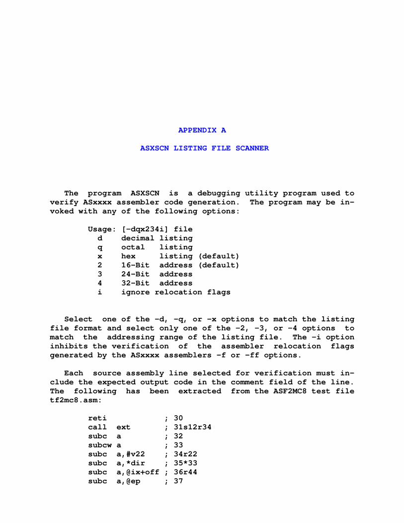
APPENDIX A
ASXSCN LISTING FILE SCANNER
The program ASXSCN is a debugging utility program used to verify ASxxxx assembler code generation. The program may be in- voked with any of the following options:
Usage: [-dqx234i] file d decimal listing q octal listing x hex listing (default) 2 16-Bit address (default) 3 24-Bit address 4 32-Bit address i ignore relocation flags
Select one of the -d, -q, or -x options to match the listing file format and select only one of the -2, -3, or -4 options to match the addressing range of the listing file. The -i option inhibits the verification of the assembler relocation flags generated by the ASxxxx assemblers -f or -ff options.
Each source assembly line selected for verification must in- clude the expected output code in the comment field of the line. The following has been extracted from the ASF2MC8 test file tf2mc8.asm:
reti ; 30 call ext ; 31s12r34 subc a ; 32 subcw a ; 33 subc a,#v22 ; 34r22 subc a,*dir ; 35*33 subc a,@ix+off ; 36r44 subc a,@ep ; 37
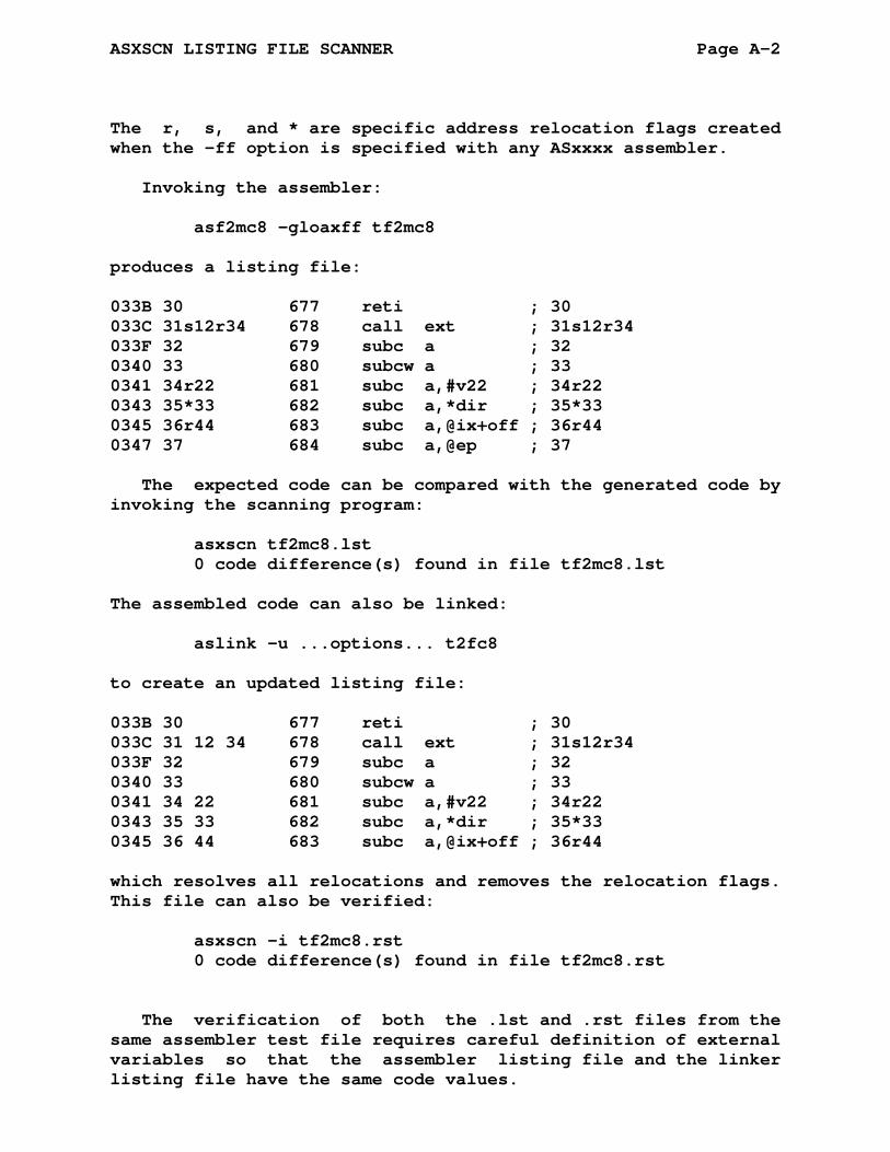
ASXSCN LISTING FILE SCANNER Page A-2
The r, s, and * are specific address relocation flags created when the -ff option is specified with any ASxxxx assembler.
Invoking the assembler:
asf2mc8 -gloaxff tf2mc8
produces a listing file:
033B 30 677 reti ; 30 033C 31s12r34 678 call ext ; 31s12r34 033F 32 679 subc a ; 32 0340 33 680 subcw a ; 33 0341 34r22 681 subc a,#v22 ; 34r22 0343 35*33 682 subc a,*dir ; 35*33 0345 36r44 683 subc a,@ix+off ; 36r44 0347 37 684 subc a,@ep ; 37
The expected code can be compared with the generated code by invoking the scanning program:
asxscn tf2mc8.lst 0 code difference(s) found in file tf2mc8.lst
The assembled code can also be linked:
aslink -u ...options... t2fc8
to create an updated listing file:
033B 30 677 reti ; 30 033C 31 12 34 678 call ext ; 31s12r34 033F 32 679 subc a ; 32 0340 33 680 subcw a ; 33 0341 34 22 681 subc a,#v22 ; 34r22 0343 35 33 682 subc a,*dir ; 35*33 0345 36 44 683 subc a,@ix+off ; 36r44
which resolves all relocations and removes the relocation flags. This file can also be verified:
asxscn -i tf2mc8.rst 0 code difference(s) found in file tf2mc8.rst
The verification of both the .lst and .rst files from the same assembler test file requires careful definition of external variables so that the assembler listing file and the linker listing file have the same code values.

APPENDIX B
ASXCNV LISTING CONVERTER
The program ASXCNV is a debugging utility program used to create an assembler file with verification data. The program may be invoked with any of the following options:
Usage: [-dqx234] file d decimal listing q octal listing x hex listing (default) 2 16-Bit address (default) 3 24-Bit address 4 32-Bit address
Select one of the -d, -q, or -x options to match the listing file format and select only one of the -2, -3, or -4 options to match the addressing range of the listing file.
Each source assembly line which creates output data will have the data appended to the source line as a comment. The appended comment will contain the relocation codes if they are present in the listing file. Any existing comment on the line will be overwritten.
Given an existing listing file, a.lst, containing:
033B 30 677 reti 033C 31s12r34 678 call ext 033F 32 679 subc a 0340 33 680 subcw a 0341 34r22 681 subc a,#v22 0343 35*33 682 subc a,*dir 0345 36r44 683 subc a,@ix+off 0347 37 684 subc a,@ep
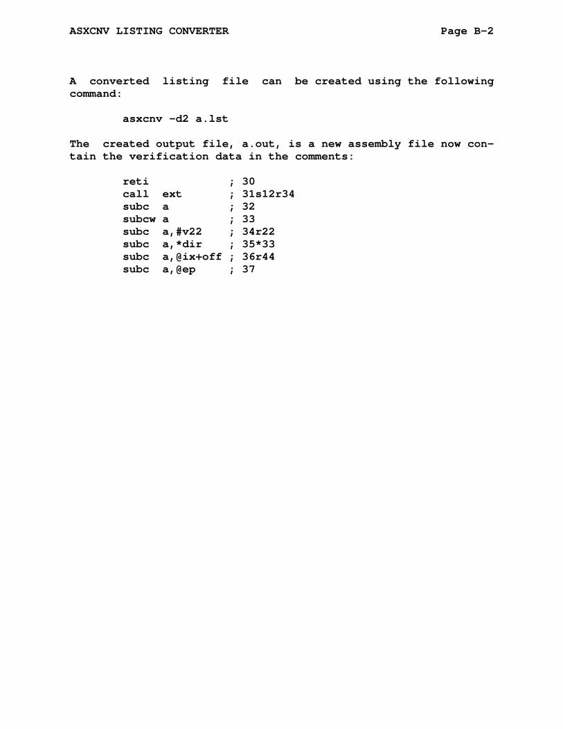
ASXCNV LISTING CONVERTER Page B-2
A converted listing file can be created using the following command:
asxcnv -d2 a.lst
The created output file, a.out, is a new assembly file now con- tain the verification data in the comments:
reti ; 30 call ext ; 31s12r34 subc a ; 32 subcw a ; 33 subc a,#v22 ; 34r22 subc a,*dir ; 35*33 subc a,@ix+off ; 36r44 subc a,@ep ; 37
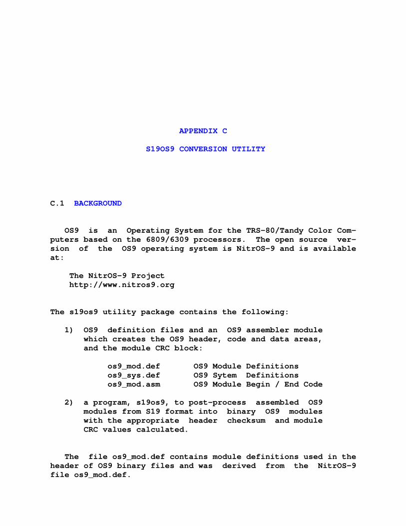
APPENDIX C
S19OS9 CONVERSION UTILITY
C.1 BACKGROUND
OS9 is an Operating System for the TRS-80/Tandy Color Com- puters based on the 6809/6309 processors. The open source ver- sion of the OS9 operating system is NitrOS-9 and is available at:
The NitrOS-9 Project http://www.nitros9.org The s19os9 utility package contains the following: 1) OS9 definition files and an OS9 assembler module which creates the OS9 header, code and data areas, and the module CRC block: os9_mod.def OS9 Module Definitions os9_sys.def OS9 Sytem Definitions os9_mod.asm OS9 Module Begin / End Code 2) a program, s19os9, to post-process assembled OS9 modules from S19 format into binary OS9 modules with the appropriate header checksum and module CRC values calculated.
The file os9_mod.def contains module definitions used in the header of OS9 binary files and was derived from the NitrOS-9 file os9_mod.def.
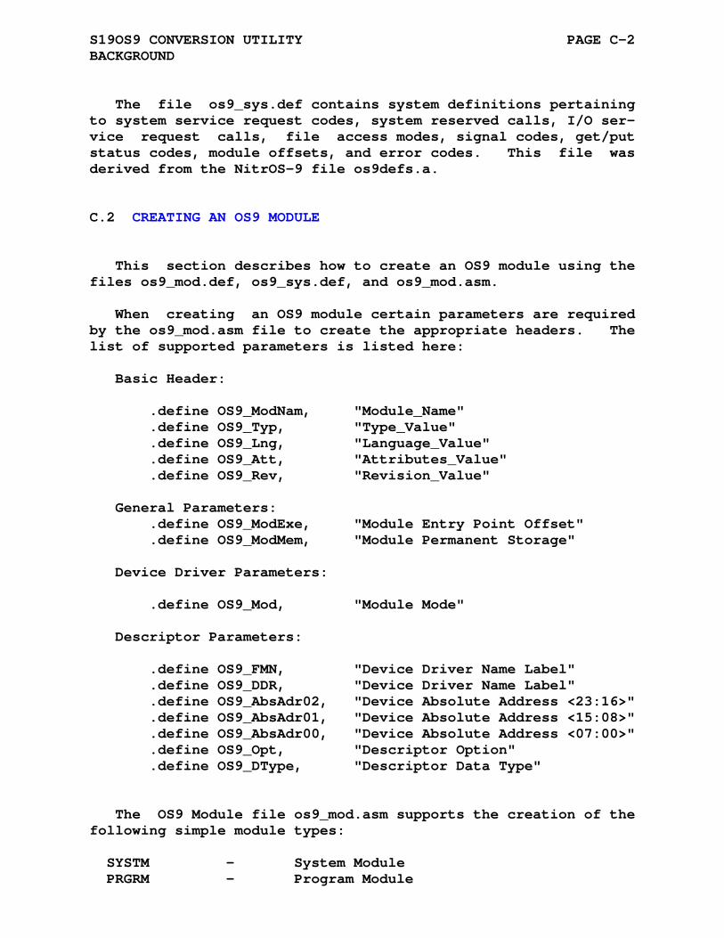
S19OS9 CONVERSION UTILITY PAGE C-2 BACKGROUND
The file os9_sys.def contains system definitions pertaining to system service request codes, system reserved calls, I/O ser- vice request calls, file access modes, signal codes, get/put status codes, module offsets, and error codes. This file was derived from the NitrOS-9 file os9defs.a.
C.2 CREATING AN OS9 MODULE
This section describes how to create an OS9 module using the files os9_mod.def, os9_sys.def, and os9_mod.asm.
When creating an OS9 module certain parameters are required by the os9_mod.asm file to create the appropriate headers. The list of supported parameters is listed here:
Basic Header: .define OS9_ModNam, "Module_Name" .define OS9_Typ, "Type_Value" .define OS9_Lng, "Language_Value" .define OS9_Att, "Attributes_Value" .define OS9_Rev, "Revision_Value" General Parameters: .define OS9_ModExe, "Module Entry Point Offset" .define OS9_ModMem, "Module Permanent Storage" Device Driver Parameters: .define OS9_Mod, "Module Mode" Descriptor Parameters: .define OS9_FMN, "Device Driver Name Label" .define OS9_DDR, "Device Driver Name Label" .define OS9_AbsAdr02, "Device Absolute Address <23:16>" .define OS9_AbsAdr01, "Device Absolute Address <15:08>" .define OS9_AbsAdr00, "Device Absolute Address <07:00>" .define OS9_Opt, "Descriptor Option" .define OS9_DType, "Descriptor Data Type"
The OS9 Module file os9_mod.asm supports the creation of the following simple module types:
SYSTM - System Module PRGRM - Program Module

S19OS9 CONVERSION UTILITY PAGE C-3 CREATING AN OS9 MODULE
SBTRN - Subroutine Module DRIVR - Device Driver Module FLMGR - File Manager Module DEVIC - Device Descriptor Module
The following code shows the steps required when creating an OS9 program using the os9_mod.asm file. os9_mod.asm loads the os9_mod.def and os9_sys.def files, defines the software inter- rupt macro os9, and creates the os9 program header and crc blocks.
C.2.1 Step 1: Define Header Values
;**** ; Step 1: ; Use the .define assembler directive ; to insert the parameters into the ; os9_mod.asm's header structure. ; ; Note: See the file os9_mod.asm for ; parameter names and definitions. ; .title List Program .sbttl Header Definitions .define OS9_ModNam, "LSTNAM" .define OS9_Typ, "PRGRM" .define OS9_Lng, "OBJCT" .define OS9_Att, "REENT" .define OS9_Rev, "1" .define OS9_ModExe, "LSTENT" .define OS9_ModMem, "LSTMEM"
C.2.2 Step 2: Create The Module Header
; Step 2: ; Set the symbol OS9_Module equal to 1 ; and .include the file os9_mod.asm. OS9_Module = 1 ; OS9 Module Begin (==1) ; .include "os9_mod.asm" .nlist .include "os9_mod.asm" .list
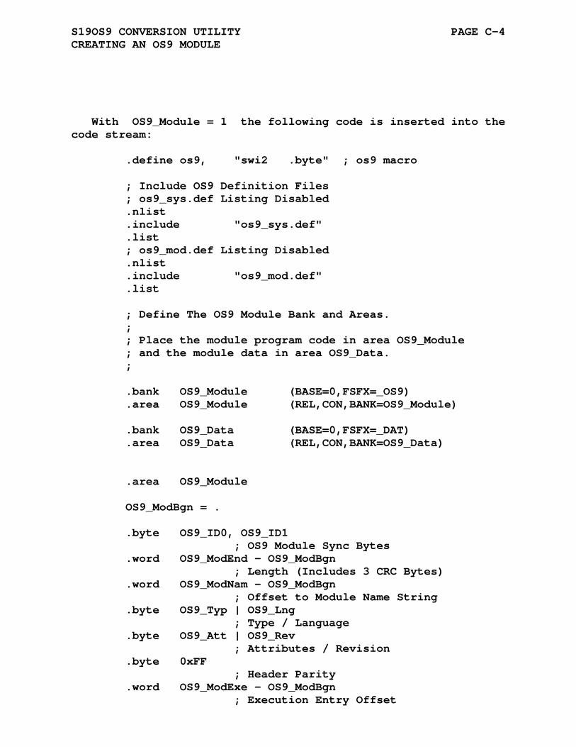
S19OS9 CONVERSION UTILITY PAGE C-4 CREATING AN OS9 MODULE
With OS9_Module = 1 the following code is inserted into the code stream:
.define os9, "swi2 .byte" ; os9 macro ; Include OS9 Definition Files ; os9_sys.def Listing Disabled .nlist .include "os9_sys.def" .list ; os9_mod.def Listing Disabled .nlist .include "os9_mod.def" .list ; Define The OS9 Module Bank and Areas. ; ; Place the module program code in area OS9_Module ; and the module data in area OS9_Data. ; .bank OS9_Module (BASE=0,FSFX=_OS9) .area OS9_Module (REL,CON,BANK=OS9_Module) .bank OS9_Data (BASE=0,FSFX=_DAT) .area OS9_Data (REL,CON,BANK=OS9_Data) .area OS9_Module OS9_ModBgn = . .byte OS9_ID0, OS9_ID1 ; OS9 Module Sync Bytes .word OS9_ModEnd - OS9_ModBgn ; Length (Includes 3 CRC Bytes) .word OS9_ModNam - OS9_ModBgn ; Offset to Module Name String .byte OS9_Typ | OS9_Lng ; Type / Language .byte OS9_Att | OS9_Rev ; Attributes / Revision .byte 0xFF ; Header Parity .word OS9_ModExe - OS9_ModBgn ; Execution Entry Offset

S19OS9 CONVERSION UTILITY PAGE C-5 CREATING AN OS9 MODULE
.word OS9_ModMem ; Storage Requirement ; OS9_ModData ; Module Data
C.2.3 Step 3: Allocate Storage
The next step is to add the program data storage space for the program. Note that the space is only allocated here and no initialization is done.
;*****-----*****-----*****-----*****-----*****-----***** ; LIST UTILITY COMMAND ; Syntax: list <pathname> ; COPIES INPUT FROM SPECIFIED FILE TO STANDARD OUTPUT ; Step 3: ; Allocate the storage in .area OS9_Data .area OS9_Data ; STATIC STORAGE OFFSETS BUFSIZ .equ 200 ; size of input buffer Base = . IPATH = . - Base .rmb 1 ; input path number PRMPTR = . - Base .rmb 2 ; parameter pointer BUFFER = . - Base .rmb BUFSIZ ; allocate line buffer .rmb 200 ; allocate stack .rmb 200 ; room for parameter list LSTMEM = . - Base
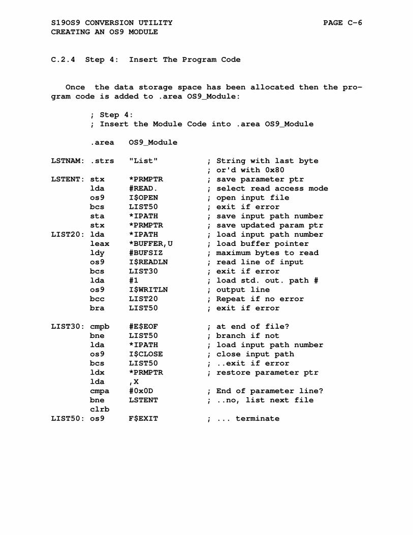
S19OS9 CONVERSION UTILITY PAGE C-6 CREATING AN OS9 MODULE
C.2.4 Step 4: Insert The Program Code
Once the data storage space has been allocated then the pro- gram code is added to .area OS9_Module:
; Step 4: ; Insert the Module Code into .area OS9_Module .area OS9_Module LSTNAM: .strs "List" ; String with last byte ; or'd with 0x80 LSTENT: stx *PRMPTR ; save parameter ptr lda #READ. ; select read access mode os9 I$OPEN ; open input file bcs LIST50 ; exit if error sta *IPATH ; save input path number stx *PRMPTR ; save updated param ptr LIST20: lda *IPATH ; load input path number leax *BUFFER,U ; load buffer pointer ldy #BUFSIZ ; maximum bytes to read os9 I$READLN ; read line of input bcs LIST30 ; exit if error lda #1 ; load std. out. path # os9 I$WRITLN ; output line bcc LIST20 ; Repeat if no error bra LIST50 ; exit if error LIST30: cmpb #E$EOF ; at end of file? bne LIST50 ; branch if not lda *IPATH ; load input path number os9 I$CLOSE ; close input path bcs LIST50 ; ..exit if error ldx *PRMPTR ; restore parameter ptr lda ,X cmpa #0x0D ; End of parameter line? bne LSTENT ; ..no, list next file clrb LIST50: os9 F$EXIT ; ... terminate
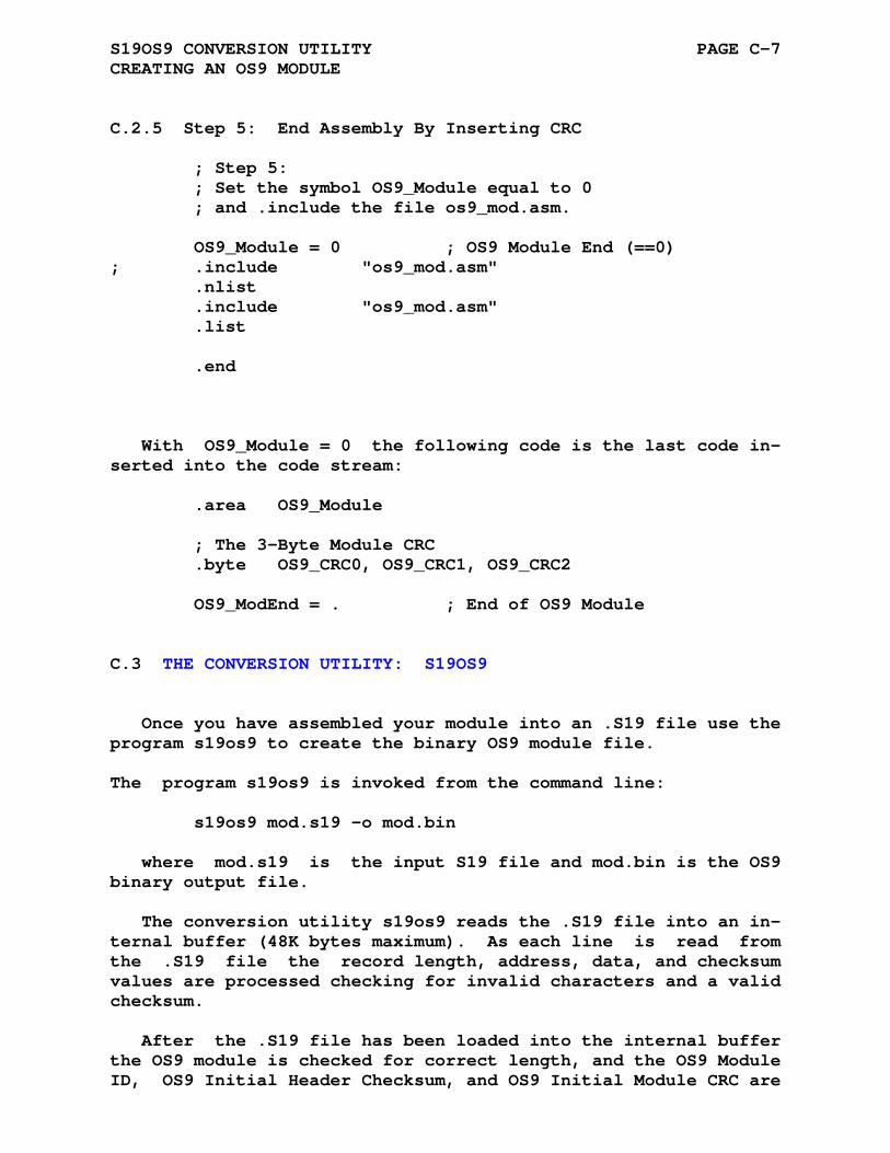
S19OS9 CONVERSION UTILITY PAGE C-7 CREATING AN OS9 MODULE
C.2.5 Step 5: End Assembly By Inserting CRC
; Step 5: ; Set the symbol OS9_Module equal to 0 ; and .include the file os9_mod.asm. OS9_Module = 0 ; OS9 Module End (==0) ; .include "os9_mod.asm" .nlist .include "os9_mod.asm" .list .end
With OS9_Module = 0 the following code is the last code in- serted into the code stream:
.area OS9_Module ; The 3-Byte Module CRC .byte OS9_CRC0, OS9_CRC1, OS9_CRC2 OS9_ModEnd = . ; End of OS9 Module
C.3 THE CONVERSION UTILITY: S19OS9
Once you have assembled your module into an .S19 file use the program s19os9 to create the binary OS9 module file.
The program s19os9 is invoked from the command line: s19os9 mod.s19 -o mod.bin
where mod.s19 is the input S19 file and mod.bin is the OS9 binary output file.
The conversion utility s19os9 reads the .S19 file into an in- ternal buffer (48K bytes maximum). As each line is read from the .S19 file the record length, address, data, and checksum values are processed checking for invalid characters and a valid checksum.
After the .S19 file has been loaded into the internal buffer the OS9 module is checked for correct length, and the OS9 Module ID, OS9 Initial Header Checksum, and OS9 Initial Module CRC are
S19OS9 CONVERSION UTILITY PAGE C-8 THE CONVERSION UTILITY: S19OS9
verified. After these parameters have been checked then the ac- tual header checksum and module CRC values are calculated and replace the Initial Module Checksum and CRC values. The final- ized module is then written to the file mod.bin.
APPENDIX D
RELEASE NOTES
Asxxxx/ASlink version 5.30 is considered a major release ver- sion.
January 2019 Version 5.3 (1) Added new assemblers: as78k0, as8008, as8008s, as8x300, and asz280 (2) General assembler updates added -i to insert assember lines before input files fixed .macro listing options fixes related to <q> errors and the -bb option fix the escape processing of the '\' character .include file location illustrations (3) General linker updates fix library path file strings rewrite of .lst to .rst translation (4) Assembler specific fixes as740 changed 2-byte code to 1-byte code definition as8048 Corrected bug in "sel" instruction in .8041 mode. asf2mc Corrected documentation for asf2mc processor types. aspic Fixed missing machine type variable definition Fixed 'tris' instruction
RELEASE NOTES Page D-2
asst8 Included add/addw/sub/subw sp,#byte modes. Added the int opcode. Cleaned up st8addr.c addressing mode comments and code.
January 2017 Version 5.20 (1) Completed the functionality for propagating the boundary specifications .odd, .even, and .bndry processed during assembly to the linker. (2) Restored the correct functionality of the .org directive in areas of REL type. (3) Added Intel Hex legacy start address record type 1 as an option.
Summary of changes/additions to the ASxxxx Assemblers from Ver- sion 5.11 to Version 4.11.
2015_06_27 Version 5.10 Update 1 This update for Version 5.10 of the ASxxxx Cross Assemblers includes fixes for the following errors: (1) The as6500 assembler incorrectly assembled cpx # and cpy # instructions. (2) An error in asmain.c inhibited the listing of all .if.. assembly directives.
2014_10_31 Version 5.10 (1) Rewrite of listing to relocated listing translation code in the assembler and the linker base code. The Assemblers now create a .lst to .rst hint file with the extension .hlr (when both .lst and .rel files are created by the assembler). (2) Add as6100 assembler (Intersil IM6100 / Harris HM6100) (3) Add as78k0s assembler (Renesas/NEC 78K/0S)
RELEASE NOTES Page D-3
2013_05_12 Version 5.00 Update 6 This update for Version 5.00 of the ASxxxx Cross Assemblers rolls up updates 1, 2, 3, 4, and 5 with fixes for the following: (1) Fix asscmp assembler (pre-increment on fetch). (2) Fix aslink error reporting for PC relative modes.
2012_08_01 Version 5.00 Update 5 Update_05 for the ASxxxx Assembler and Linker Version 5.00 (use 'pkunzip -d u05500.zip' for extraction with MS-DOS) (use 'unzip -L -a u05500.zip' for extraction with Linux) See the note about merging this update with the asxv5pxx distribution. This update for Version 5.00 of the ASxxxx Cross Assemblers rolls up updates 1, 2, 3, and 4 with the addition of a new assembler and fixes: (1) A new cross assembler for the Fairchild F8 microprocessor (or Mostek 3870). (2) Minor syntactical changes for ANSI C compatability, fix type conversion warnings, and update the various build, make, and test files. Update 4 Items (1) The AS8048 base opcode value for the JMPP instruction should be B3 and NOT 83. (2) The AS8051 assembler calculates incorrect offsets when using the program counter, ".", as a destination in the instructions having a PC-Relative addressing mode. These instructions include: jbc, jb, jbn, jc, jnc, jz, jnz, cjne, and djnz.

RELEASE NOTES Page D-4
Update 3 Items (1) A new cross assembler for the Fairchild F8 microprocessor (or Mostek 3870). (2) Minor syntactical changes for ANSI C compatability, fix type conversion warnings, and update the various build, make, and test files. (3) New cross assemblers for STMicroelectronics ST6, ST7, and STM8 microprocessors. (4) An ASlink list file update error fix (-u option) causing some errors not to be inserted into the created .rst file. (5) An additional ASxxxx assembler option (-v) which enables checking for out of range signed / unsigned values in symbol equates and arithmetic operations. This option has some ambiguities as internally the assemblers use unsigned arithmetic for calculations. (e.g. for a 2-byte machine -32768 and 32768 are both represented as 0x8000) Update 2 Items (1) When using the assembler directive .end to specify the code entry address the assembler fails to set the variable .__.END. as a global. Therefor the value of .__.END. is not passed to the linker and the start address frame is always zero. (2) The linker will fail to create a start address frame when there is no code generated within the area/bank referenced by the .__.END. variable. Update 1 Items (1) The newest versions of gcc (and perhaps other compilers) give warnings about missing arguments in the fprintf() function. This update replaces fprintf(arg1, arg2) with fprintf(arg1, "%s", arg2) in each affected line of code. (2) The newest versions of gcc (and perhaps other compilers) have defined 'getline' as a standard

RELEASE NOTES Page D-5
function in 'stdio.h'. This conflicts with the function 'getline()' in the ASxxxx package. All references to 'getline()' have been changed to 'nxtline()'. Before merging the asxv5pxx directory and subdirectories with the V5.00 distribution the following files/directories must be deleted: [asxv5pxx\asf2mc8\f8mch.c [asxv5pxx\asf2mc8\f8adr.c [asxv5pxx\asf2mc8\f8pst.c [asxv5pxx\asf2mc8\f8.h [asxv5pxx\asxmak\vc6\asf2mc8] [asxv5pxx\asxmak\vs05\asf2mc8]
2011_07_24 Version 5.00 Update 4 This update for Version 5.00 of the ASxxxx Cross Assemblers includes fixes for the following errors: (1) The AS8048 base opcode value for the JMPP instruction should be B3 and NOT 83. (2) The AS8051 assembler calculates incorrect offsets when using the program counter, ".", as a destination in the instructions having a PC-Relative addressing mode. These instructions include: jbc, jb, jbn, jc, jnc, jz, jnz, cjne, and djnz.
2010_10_31 Version 5.00 Update 3 This update for Version 5.00 of the ASxxxx Cross Assemblers rolls up updates 1 and 2 with the addition of three new assemblers and fixes: (1) New cross assemblers for STMicroelectronics ST6, ST7, and STM8 microprocessors. (2) An ASlink list file update error fix (-u option) causing some errors not to be inserted into the created .rst file.
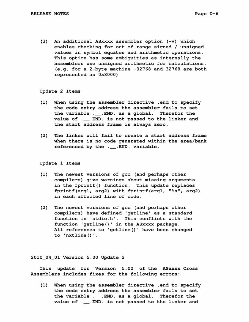
RELEASE NOTES Page D-6
(3) An additional ASxxxx assembler option (-v) which enables checking for out of range signed / unsigned values in symbol equates and arithmetic operations. This option has some ambiguities as internally the assemblers use unsigned arithmetic for calculations. (e.g. for a 2-byte machine -32768 and 32768 are both represented as 0x8000) Update 2 Items (1) When using the assembler directive .end to specify the code entry address the assembler fails to set the variable .__.END. as a global. Therefor the value of .__.END. is not passed to the linker and the start address frame is always zero. (2) The linker will fail to create a start address frame when there is no code generated within the area/bank referenced by the .__.END. variable. Update 1 Items (1) The newest versions of gcc (and perhaps other compilers) give warnings about missing arguments in the fprintf() function. This update replaces fprintf(arg1, arg2) with fprintf(arg1, "%s", arg2) in each affected line of code. (2) The newest versions of gcc (and perhaps other compilers) have defined 'getline' as a standard function in 'stdio.h'. This conflicts with the function 'getline()' in the ASxxxx package. All references to 'getline()' have been changed to 'nxtline()'.
2010_04_01 Version 5.00 Update 2 This update for Version 5.00 of the ASxxxx Cross Assemblers includes fixes for the following errors: (1) When using the assembler directive .end to specify the code entry address the assembler fails to set the variable .__.END. as a global. Therefor the value of .__.END. is not passed to the linker and

RELEASE NOTES Page D-7
the start address frame is always zero. (2) The linker will fail to create a start address frame when there is no code generated within the area/bank referenced by the .__.END. variable.
2010_03_03 Version 5.00 Update 1 This update for Version 5.00 of the ASxxxx Cross Assemblers includes fixes for the following errors: (1) The newest versions of gcc (and perhaps other compilers) give warnings about missing arguments in the fprintf() function. This update replaces fprintf(arg1, arg2) with fprintf(arg1, "%s", arg2) in each affected line of code. (2) The newest versions of gcc (and perhaps other compilers) have defined 'getline' as a standard function in 'stdio.h'. This conflicts with the function 'getline()' in the ASxxxx package. All references to 'getline()' have been changed to 'nxtline()'.
2009_04_01 (Version 5.00)
Added a general purpose macro processor to the ASxxxx assem- blers.
Added true (t), false (f), and true or false (tf) condition- als to the .if / .else / .endif construct. The conditionals .ift, .iff, and .iftf allow replacement of the .else directive making the .if / .endif construct more readable.
e.g. .ift if condition is true
An alternate .if construction has been added to the ASxxxx assemblers:
e.g. .if eq,... if argument == 0
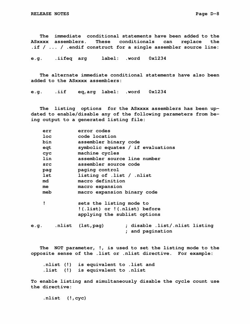
RELEASE NOTES Page D-8
The immediate conditional statements have been added to the ASxxxx assemblers. These conditionals can replace the .if / ... / .endif construct for a single assembler source line:
e.g. .iifeq arg label: .word 0x1234
The alternate immediate conditional statements have also been added to the ASxxxx assemblers:
e.g. .iif eq,arg label: .word 0x1234
The listing options for the ASxxxx assemblers has been up- dated to enable/disable any of the following parameters from be- ing output to a generated listing file:
err error codes loc code location bin assembler binary code eqt symbolic equates / if evaluations cyc machine cycles lin assembler source line number src assembler source code pag paging control lst listing of .list / .nlist md macro definition me macro expansion meb macro expansion binary code ! sets the listing mode to !(.list) or !(.nlist) before applying the sublist options e.g. .nlist (lst,pag) ; disable .list/.nlist listing ; and pagination
The NOT parameter, !, is used to set the listing mode to the opposite sense of the .list or .nlist directive. For example:
.nlist (!) is equivalent to .list and .list (!) is equivalent to .nlist
To enable listing and simultaneously disable the cycle count use the directive:
.nlist (!,cyc)
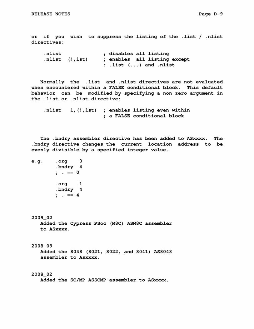
RELEASE NOTES Page D-9
or if you wish to suppress the listing of the .list / .nlist directives:
.nlist ; disables all listing .nlist (!,lst) ; enables all listing except : .list (...) and .nlist
Normally the .list and .nlist directives are not evaluated when encountered within a FALSE conditional block. This default behavior can be modified by specifying a non zero argument in the .list or .nlist directive:
.nlist 1,(!,lst) ; enables listing even within ; a FALSE conditional block
The .bndry assembler directive has been added to ASxxxx. The .bndry directive changes the current location address to be evenly divisible by a specified integer value.
e.g. .org 0 .bndry 4 ; . == 0 .org 1 .bndry 4 ; . == 4
2009_02 Added the Cypress PSoc (M8C) ASM8C assembler to ASxxxx. 2008_09 Added the 8048 (8021, 8022, and 8041) AS8048 assembler to Asxxxx. 2008_02 Added the SC/MP ASSCMP assembler to ASxxxx.
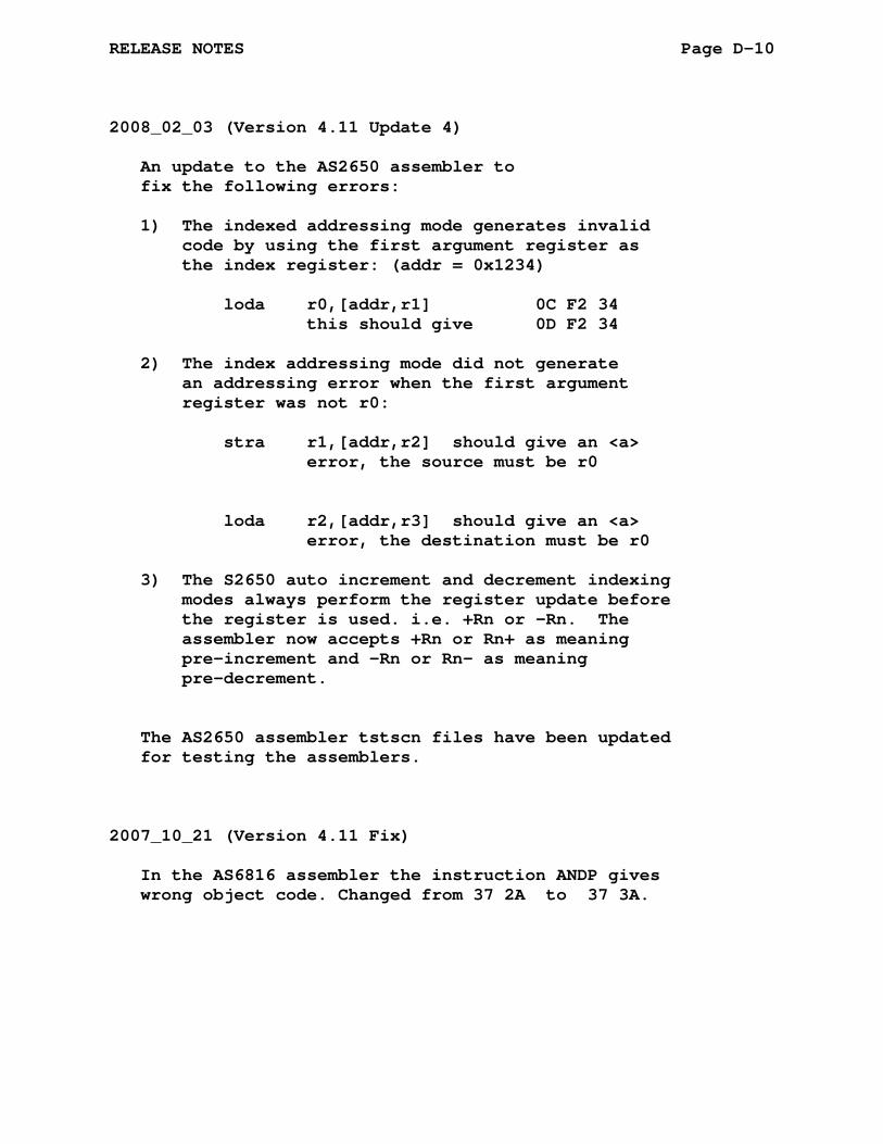
RELEASE NOTES Page D-10
2008_02_03 (Version 4.11 Update 4) An update to the AS2650 assembler to fix the following errors: 1) The indexed addressing mode generates invalid code by using the first argument register as the index register: (addr = 0x1234) loda r0,[addr,r1] 0C F2 34 this should give 0D F2 34 2) The index addressing mode did not generate an addressing error when the first argument register was not r0: stra r1,[addr,r2] should give an <a> error, the source must be r0 loda r2,[addr,r3] should give an <a> error, the destination must be r0 3) The S2650 auto increment and decrement indexing modes always perform the register update before the register is used. i.e. +Rn or -Rn. The assembler now accepts +Rn or Rn+ as meaning pre-increment and -Rn or Rn- as meaning pre-decrement. The AS2650 assembler tstscn files have been updated for testing the assemblers. 2007_10_21 (Version 4.11 Fix) In the AS6816 assembler the instruction ANDP gives wrong object code. Changed from 37 2A to 37 3A.

RELEASE NOTES Page D-11
2007_04_01 (Version 4.11 Update 3) An update to the ASPIC assembler and associated fix to ASLINK: 1) Change the pic addressing to lo/hi from hi/lo byte ordering. 2) The update fixes an error in the pic17 series LCALL instruction. 3) A rewrite of the pic18 series assembler to change the PC addressing from 1 per 16-bit word to 1 per 8-bit byte and add the extended instruction set. 4) Modify the Linker Merge Mode processing to take into account the discarded low order bits for PC Relative Addressing. 5) New tstscn files for testing the assemblers. 2006_11_01 (Version 4.11 Optional Update 2) 1) OS9 definition files and an OS9 assembler module which creates the OS9 header, code and data areas, and the module CRC block: os9_mod.def OS9 Module Definitions os9_sys.def OS9 Sytem Definitions os9_mod.asm OS9 Module Begin / End Code 2) a program, s19os9, to post-process assembled OS9 modules in S19 format into binary OS9 modules with the appropriate header checksum and module CRC values calculated. 3) new make and project files which may be used to compile the s19os9 program.
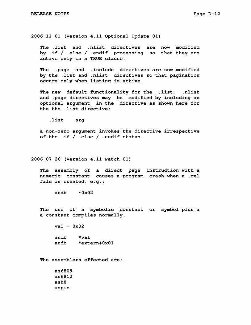
RELEASE NOTES Page D-12
2006_11_01 (Version 4.11 Optional Update 01) The .list and .nlist directives are now modified by .if / .else / .endif processing so that they are active only in a TRUE clause. The .page and .include directives are now modified by the .list and .nlist directives so that pagination occurs only when listing is active. The new default functionality for the .list, .nlist and .page directives may be modified by including an optional argument in the directive as shown here for the the .list directive: .list arg a non-zero argument invokes the directive irrespective of the .if / .else / .endif status. 2006_07_26 (Version 4.11 Patch 01) The assembly of a direct page instruction with a numeric constant causes a program crash when a .rel file is created. e.g.: andb *0x02 The use of a symbolic constant or symbol plus a a constant compiles normally. val = 0x02 andb *val andb *extern+0x01 The assemblers effected are: as6809 as6812 ash8 aspic

RELEASE NOTES Page D-13
Summary of changes/additions to the ASxxxx Assemblers from Version 4.10 to Version 4.11.
1. Incorporated the patches contained in p01410.zip which corrected a coding error that affected BANKS containing multiple ABS areas or mixed AREA types.
2. Incorporated the patches contained in p02410.zip which corrected improper use of R_USGN in most addressing modes in AS6500. This caused unexpected <a> errors in V4.xx because of the ASxxxx core change to 32-bit in- tegers and arithmetic.
3. Incorporated the patches contained in p03410.zip which corrected errors in the .local and .globl assembler directive processing routine that introduced unwanted side effects for variable and symbol definition files. These effects included improper definitions and incor- rect error warnings.
4. The following new subdirectories and their files have been added to the asxtst directory:
* areabank Area and Bank Processing Test This directory contains several test programs: ts.asm (single file - multiple areas), tm1.asm and tm2.asm (multiple file - multiple areas), and tbm.asm, tbm1.asm, and tbm2.asm ( multiple file - multiple areas within a bank) and several other files which verify the correct operation of the linker when used with a single linked file, multi- ple linked files having no banking, and multiple linked files with banking. These reference files show in detail how the .area and .bank directives work together.
* equtst Equate Processing Test This directory contains a test file for verifying the operation of the .globl, .local, .equ, .gblequ, and .lclequ directives and the =, ==, and =: equalities.
* inctst Nested Include File Test
* itst Include File Error Reporting Test
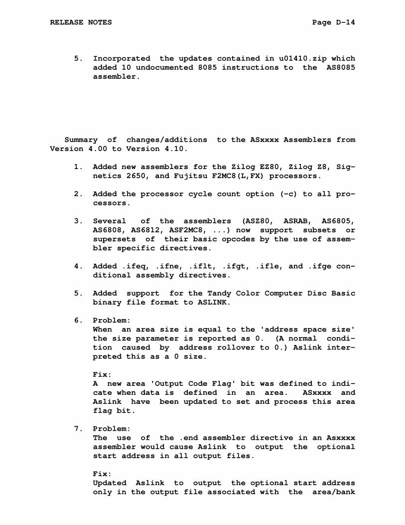
RELEASE NOTES Page D-14
5. Incorporated the updates contained in u01410.zip which added 10 undocumented 8085 instructions to the AS8085 assembler.
Summary of changes/additions to the ASxxxx Assemblers from Version 4.00 to Version 4.10.
1. Added new assemblers for the Zilog EZ80, Zilog Z8, Sig- netics 2650, and Fujitsu F2MC8(L,FX) processors.
2. Added the processor cycle count option (-c) to all pro- cessors.
3. Several of the assemblers (ASZ80, ASRAB, AS6805, AS6808, AS6812, ASF2MC8, ...) now support subsets or supersets of their basic opcodes by the use of assem- bler specific directives.
4. Added .ifeq, .ifne, .iflt, .ifgt, .ifle, and .ifge con- ditional assembly directives.
5. Added support for the Tandy Color Computer Disc Basic binary file format to ASLINK.
6. Problem: When an area size is equal to the 'address space size' the size parameter is reported as 0. (A normal condi- tion caused by address rollover to 0.) Aslink inter- preted this as a 0 size.
Fix: A new area 'Output Code Flag' bit was defined to indi- cate when data is defined in an area. ASxxxx and Aslink have been updated to set and process this area flag bit.
7. Problem: The use of the .end assembler directive in an Asxxxx assembler would cause Aslink to output the optional start address in all output files.
Fix: Updated Aslink to output the optional start address only in the output file associated with the area/bank
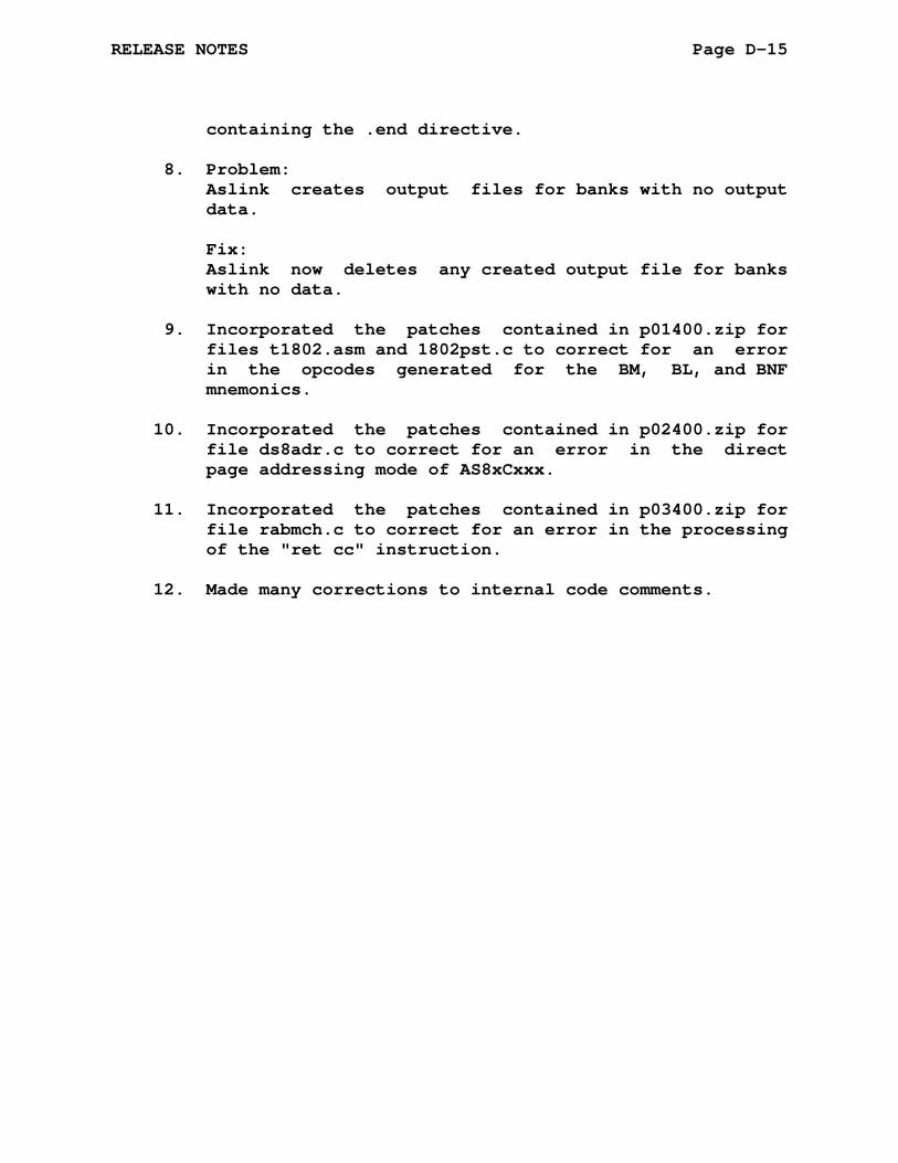
RELEASE NOTES Page D-15
containing the .end directive.
8. Problem: Aslink creates output files for banks with no output data.
Fix: Aslink now deletes any created output file for banks with no data.
9. Incorporated the patches contained in p01400.zip for files t1802.asm and 1802pst.c to correct for an error in the opcodes generated for the BM, BL, and BNF mnemonics.
10. Incorporated the patches contained in p02400.zip for file ds8adr.c to correct for an error in the direct page addressing mode of AS8xCxxx.
11. Incorporated the patches contained in p03400.zip for file rabmch.c to correct for an error in the processing of the "ret cc" instruction.
12. Made many corrections to internal code comments.
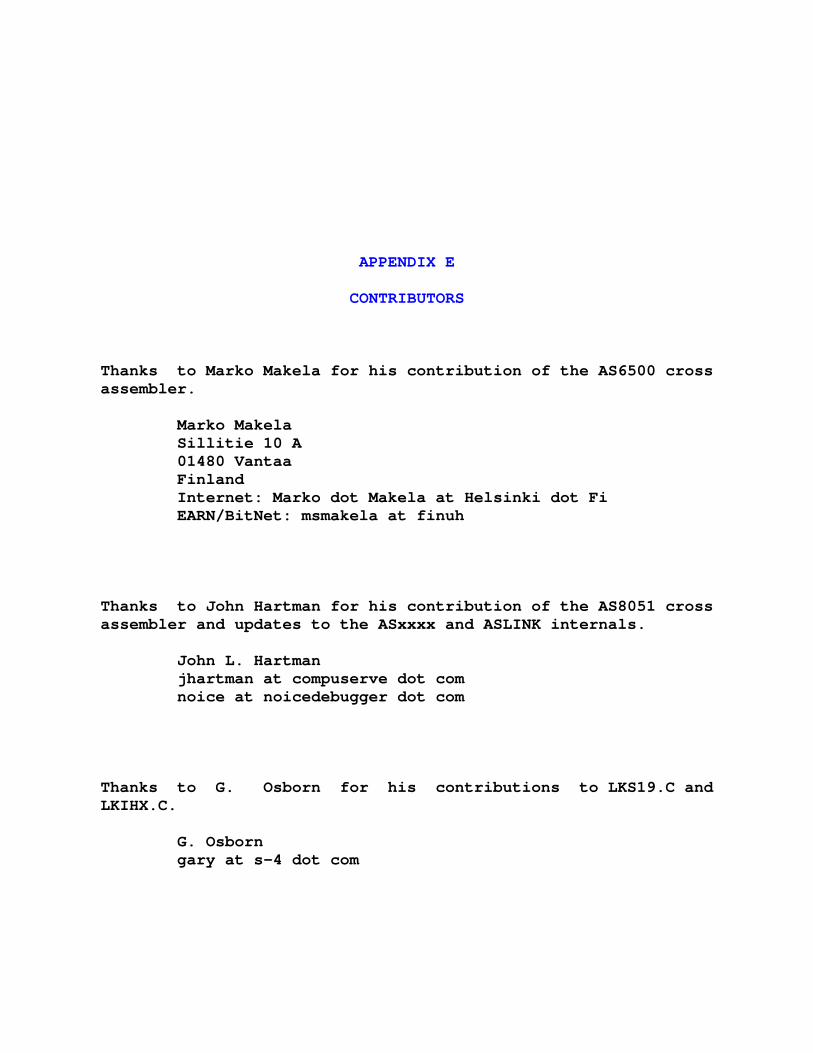
APPENDIX E
CONTRIBUTORS
Thanks to Marko Makela for his contribution of the AS6500 cross assembler.
Marko Makela Sillitie 10 A 01480 Vantaa Finland Internet: Marko dot Makela at Helsinki dot Fi EARN/BitNet: msmakela at finuh
Thanks to John Hartman for his contribution of the AS8051 cross assembler and updates to the ASxxxx and ASLINK internals.
John L. Hartman jhartman at compuserve dot com noice at noicedebugger dot com
Thanks to G. Osborn for his contributions to LKS19.C and LKIHX.C.
G. Osborn gary at s-4 dot com

CONTRIBUTORS Page E-2
Thanks to Ken Hornstein for his contribution of object libraries contained in LKLIBR.C.
Ken Hornstein kenh at cmf dot nrl dot navy dot mil
Thanks to Bill McKinnon for his contributions to the AS8XCXXX cross assembler for the DS8XCXXX series of microprocessors.
Bill McKinnon w_mckinnon at conknet dot com
Thanks to Roger Ivie for his contribution of the ASGB cross as- sembler for the GameBoy.
Roger Ivie ivie at cc dot usu dot edu
Thanks to Uwe Steller for his contribution of the AS740 cross assembler.
Uwe Stellar Uwe dot Steller at t-online dot de
Thanks to Shujen Chen for his contribution of the AS1802 cross assembler.
Shugen Chen DeVry University 1221 N. Swift Road schen at devry dot edu

CONTRIBUTORS Page E-3
Thanks to Edgar Puehringer for his contribution of the AS61860 cross assembler.
Edgar Puehringer edgar_pue at yahoo dot com
Thanks to Ulrich Raich and Razaq Ijoduola for their contribution of the ASRAB cross assembler.
Ulrich Raich and Razaq Ijoduola PS Division CERN CH-1211 Geneva-23 Ulrich dot Raich at cern dot ch
Thanks to Patrick Head for his contribution of the ASEZ80 cross assembler.
Patrick Head patrick at phead dot net
Thanks to Boisy G. Pitre for contributing the .ifeq, .ifne, .ifgt, .iflt, .ifle, and .ifge conditional directives and the Tandy Color Computer Disk Basic binary output for ASLINK.
Boisy G. Pitre boisy at boisypitre dot com
CONTRIBUTORS Page E-4
Thanks to Mike McCarty for his contributions to the processor cycle count option of the ASxxxx Assemblers.
Mike McCarty mike dot mccarty at sbcglobal dot net
Thanks to Mengjin Su for his contribution of the PIC18Fxxx Ex- tended Instructions.
Mengjin Su msu at micron dot com
Thanks to Carl Rash for his contribution of the Visual Studio 2010 project files.
Carl Rash crash at triad dot rr dot com
Thanks to John Coffman for creating the Z280 assembler.
John Coffman johninsd at gmail dot com
Thanks to Mike Naberezny for suggesting the addition of the as78k0 assembler. Mike Naberezny mike at naberezny dot com
And thanks to all those who took the time to send bug reports, suggest changes, or simply sent a note of encourage- ment. These were and are greatly appreciated. Thank you.

APPENDIX AA
ASCHECK ASSEMBLER
The ASxxxx assembler ASCHECK is used to test the machine in- dependent features of the ASxxxx assemblers. The source files for the ASCHECK assembler are also useful as a template for the development of a new ASxxxx assembler.
The ASCHECK assembler has all the ASxxxx directives enabled for testing all features of the assemblers.
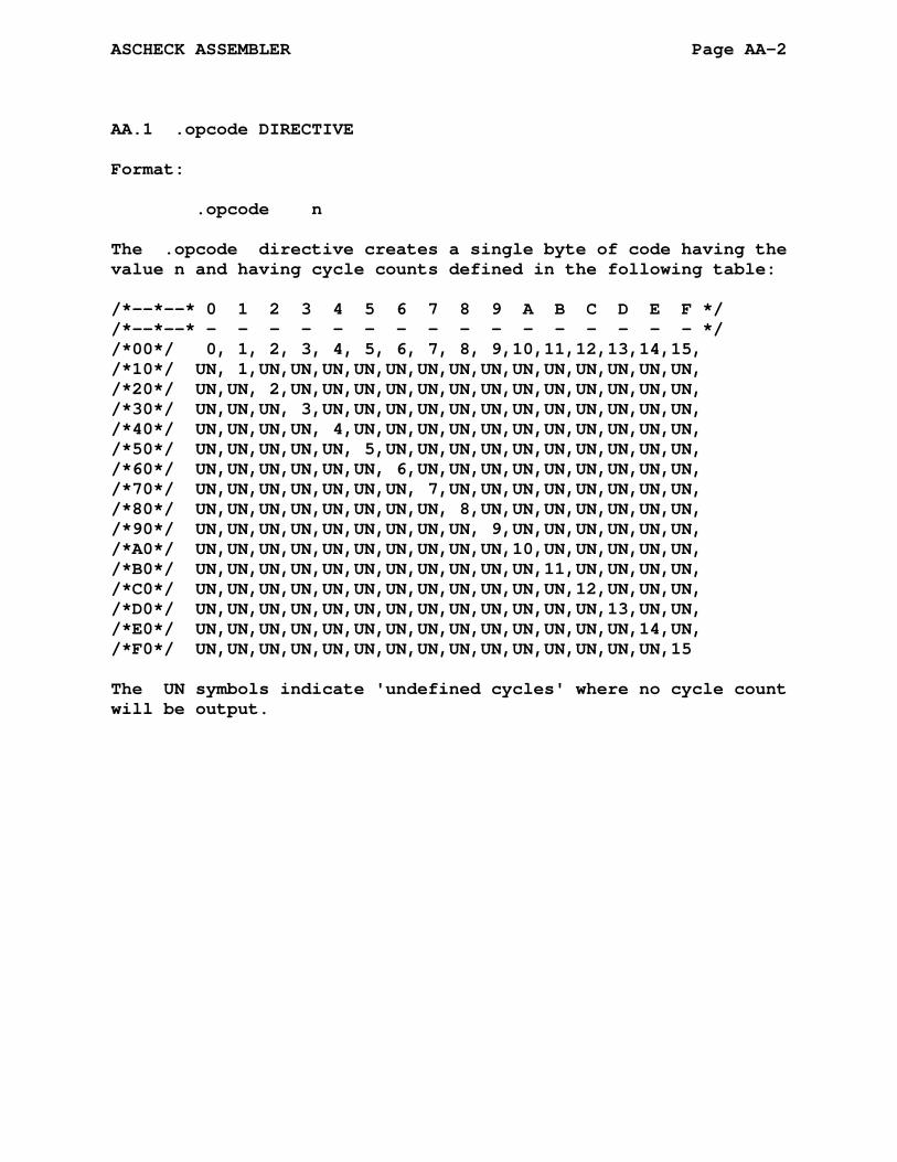
ASCHECK ASSEMBLER Page AA-2
AA.1 .opcode DIRECTIVE
Format:
.opcode n
The .opcode directive creates a single byte of code having the value n and having cycle counts defined in the following table:
/*--*--* 0 1 2 3 4 5 6 7 8 9 A B C D E F */ /*--*--* - - - - - - - - - - - - - - - - */ /*00*/ 0, 1, 2, 3, 4, 5, 6, 7, 8, 9,10,11,12,13,14,15, /*10*/ UN, 1,UN,UN,UN,UN,UN,UN,UN,UN,UN,UN,UN,UN,UN,UN, /*20*/ UN,UN, 2,UN,UN,UN,UN,UN,UN,UN,UN,UN,UN,UN,UN,UN, /*30*/ UN,UN,UN, 3,UN,UN,UN,UN,UN,UN,UN,UN,UN,UN,UN,UN, /*40*/ UN,UN,UN,UN, 4,UN,UN,UN,UN,UN,UN,UN,UN,UN,UN,UN, /*50*/ UN,UN,UN,UN,UN, 5,UN,UN,UN,UN,UN,UN,UN,UN,UN,UN, /*60*/ UN,UN,UN,UN,UN,UN, 6,UN,UN,UN,UN,UN,UN,UN,UN,UN, /*70*/ UN,UN,UN,UN,UN,UN,UN, 7,UN,UN,UN,UN,UN,UN,UN,UN, /*80*/ UN,UN,UN,UN,UN,UN,UN,UN, 8,UN,UN,UN,UN,UN,UN,UN, /*90*/ UN,UN,UN,UN,UN,UN,UN,UN,UN, 9,UN,UN,UN,UN,UN,UN, /*A0*/ UN,UN,UN,UN,UN,UN,UN,UN,UN,UN,10,UN,UN,UN,UN,UN, /*B0*/ UN,UN,UN,UN,UN,UN,UN,UN,UN,UN,UN,11,UN,UN,UN,UN, /*C0*/ UN,UN,UN,UN,UN,UN,UN,UN,UN,UN,UN,UN,12,UN,UN,UN, /*D0*/ UN,UN,UN,UN,UN,UN,UN,UN,UN,UN,UN,UN,UN,13,UN,UN, /*E0*/ UN,UN,UN,UN,UN,UN,UN,UN,UN,UN,UN,UN,UN,UN,14,UN, /*F0*/ UN,UN,UN,UN,UN,UN,UN,UN,UN,UN,UN,UN,UN,UN,UN,15
The UN symbols indicate 'undefined cycles' where no cycle count will be output.

APPENDIX AB
AS1802 ASSEMBLER
AB.1 ACKNOWLEDGMENT
Thanks to Shujen Chen for his contribution of the AS1802 cross assembler.
Shujen Chen DeVry University Tinley Park, IL schen at tp dot devry dot edu
AB.2 1802 REGISTER SET
The following is a list of the 1802 registers used by AS1802:
r0-r15 - 8-bit registers sp - register r2 pc - register r3 call - register r4 return - register r5 argr - register r6
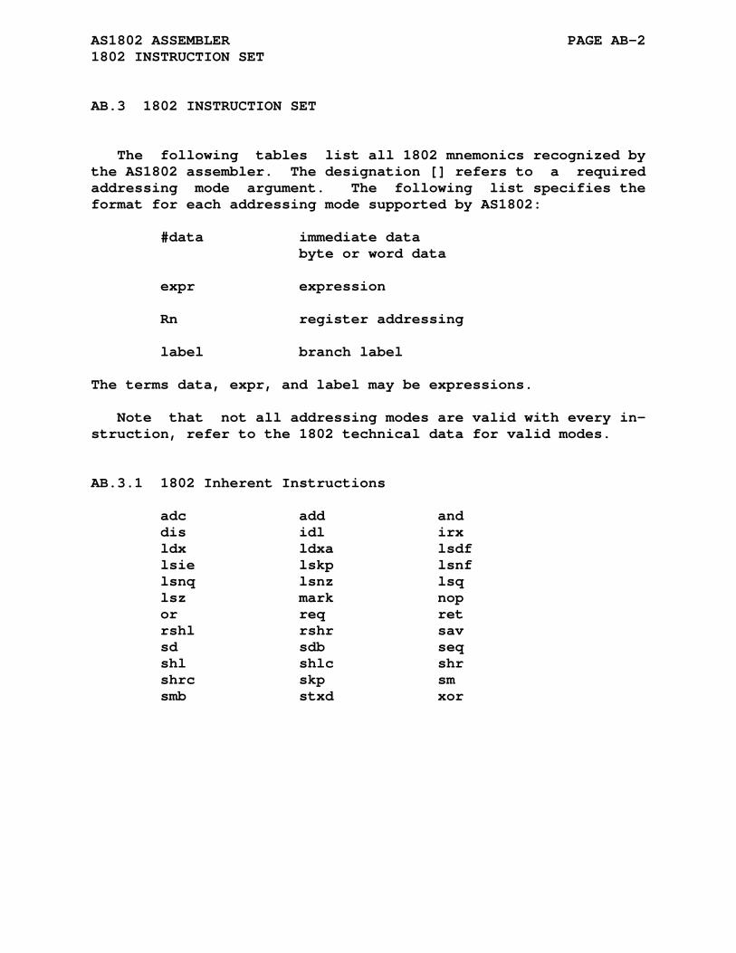
AS1802 ASSEMBLER PAGE AB-2 1802 INSTRUCTION SET
AB.3 1802 INSTRUCTION SET
The following tables list all 1802 mnemonics recognized by the AS1802 assembler. The designation [] refers to a required addressing mode argument. The following list specifies the format for each addressing mode supported by AS1802:
#data immediate data byte or word data expr expression Rn register addressing label branch label
The terms data, expr, and label may be expressions.
Note that not all addressing modes are valid with every in- struction, refer to the 1802 technical data for valid modes.
AB.3.1 1802 Inherent Instructions
adc add and dis idl irx ldx ldxa lsdf lsie lskp lsnf lsnq lsnz lsq lsz mark nop or req ret rshl rshr sav sd sdb seq shl shlc shr shrc skp sm smb stxd xor

AS1802 ASSEMBLER PAGE AB-3 1802 INSTRUCTION SET
AB.3.2 1802 Short Branch Instructions
b1 label b2 label b3 label b4 label bdf label bge label bl label bm label bn1 label bn2 label bn3 label bn4 label bnf label bnq label bnz label bpz label bq label br label bz label nbr label
AB.3.3 1802 Long Branch Instructions
lbdf label lbnf label lbnq label lbnz label lbq label lbr label lbz label nlbr label
AB.3.4 1802 Immediate Instructions
adci #data adi #data ani #data ldi #data ori #data sdbi #data sdi #data smbi #data smi #data xri #data
AB.3.5 1802 Register Instructions
dec Rn ghi Rn glo Rn inc Rn lda Rn ldn Rn phi Rn plo Rn sep Rn sex Rn str Rn

AS1802 ASSEMBLER PAGE AB-4 1802 INSTRUCTION SET
AB.3.6 1802 Input and Output Instructions
inp expr out expr

AS1802 ASSEMBLER PAGE AB-5 1802 INSTRUCTION SET
AB.3.7 CDP1802 COSMAC Microprocessor Instruction Set Summary
---------------------------------------------------------------- | | | | | RCA | | | | 1 88888 000 22222 | | 11 8 8 0 0 2 2 | | 1 8 8 0 0 0 2 | | 1 88888 0 0 0 222 | | 1 8 8 0 0 0 2 | | 1 8 8 0 0 2 | | 111 88888 000 2222222 | | | | CDP1802 COSMAC Microprocessor Instruction Set Summary | | | | | | | | | |Written by Jonathan Bowen | | Programming Research Group | | Oxford University Computing Laboratory | | 8-11 Keble Road | | Oxford OX1 3QD | | England | | | | Tel +44-865-273840 | | | |Created August 1981 | |Updated April 1985 | |Issue 1.3 Copyright (C) J.P.Bowen 1985| ----------------------------------------------------------------
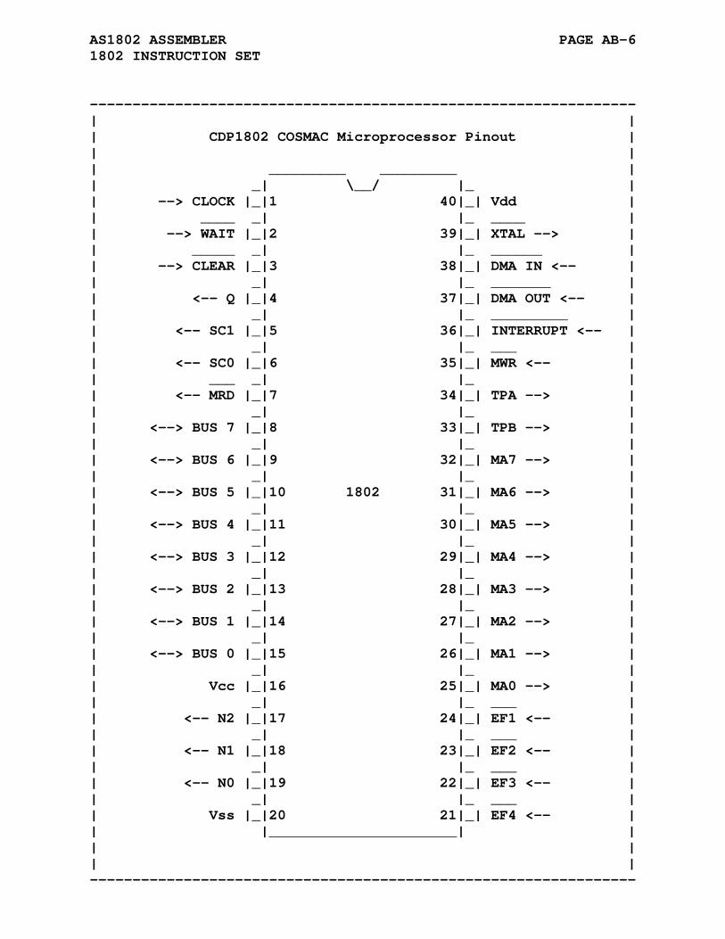
AS1802 ASSEMBLER PAGE AB-6 1802 INSTRUCTION SET
---------------------------------------------------------------- | | | CDP1802 COSMAC Microprocessor Pinout | | | | _________ _________ | | _| \__/ |_ | | --> CLOCK |_|1 40|_| Vdd | | ____ _| |_ ____ | | --> WAIT |_|2 39|_| XTAL --> | | _____ _| |_ ______ | | --> CLEAR |_|3 38|_| DMA IN <-- | | _| |_ _______ | | <-- Q |_|4 37|_| DMA OUT <-- | | _| |_ _________ | | <-- SC1 |_|5 36|_| INTERRUPT <-- | | _| |_ ___ | | <-- SC0 |_|6 35|_| MWR <-- | | ___ _| |_ | | <-- MRD |_|7 34|_| TPA --> | | _| |_ | | <--> BUS 7 |_|8 33|_| TPB --> | | _| |_ | | <--> BUS 6 |_|9 32|_| MA7 --> | | _| |_ | | <--> BUS 5 |_|10 1802 31|_| MA6 --> | | _| |_ | | <--> BUS 4 |_|11 30|_| MA5 --> | | _| |_ | | <--> BUS 3 |_|12 29|_| MA4 --> | | _| |_ | | <--> BUS 2 |_|13 28|_| MA3 --> | | _| |_ | | <--> BUS 1 |_|14 27|_| MA2 --> | | _| |_ | | <--> BUS 0 |_|15 26|_| MA1 --> | | _| |_ | | Vcc |_|16 25|_| MA0 --> | | _| |_ ___ | | <-- N2 |_|17 24|_| EF1 <-- | | _| |_ ___ | | <-- N1 |_|18 23|_| EF2 <-- | | _| |_ ___ | | <-- N0 |_|19 22|_| EF3 <-- | | _| |_ ___ | | Vss |_|20 21|_| EF4 <-- | | |______________________| | | | | | ----------------------------------------------------------------
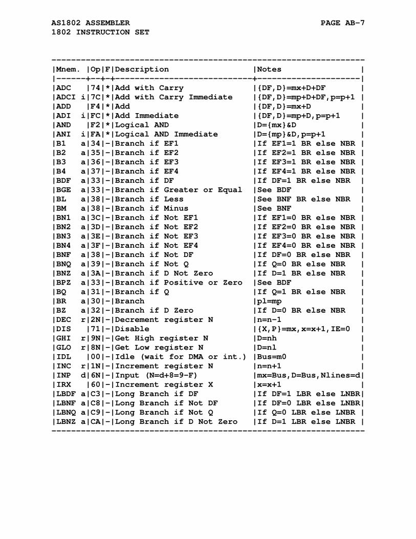
AS1802 ASSEMBLER PAGE AB-7 1802 INSTRUCTION SET
---------------------------------------------------------------- |Mnem. |Op|F|Description |Notes | |------+--+-+----------------------------+---------------------| |ADC |74|*|Add with Carry |{DF,D}=mx+D+DF | |ADCI i|7C|*|Add with Carry Immediate |{DF,D}=mp+D+DF,p=p+1 | |ADD |F4|*|Add |{DF,D}=mx+D | |ADI i|FC|*|Add Immediate |{DF,D}=mp+D,p=p+1 | |AND |F2|*|Logical AND |D={mx}&D | |ANI i|FA|*|Logical AND Immediate |D={mp}&D,p=p+1 | |B1 a|34|-|Branch if EF1 |If EF1=1 BR else NBR | |B2 a|35|-|Branch if EF2 |If EF2=1 BR else NBR | |B3 a|36|-|Branch if EF3 |If EF3=1 BR else NBR | |B4 a|37|-|Branch if EF4 |If EF4=1 BR else NBR | |BDF a|33|-|Branch if DF |If DF=1 BR else NBR | |BGE a|33|-|Branch if Greater or Equal |See BDF | |BL a|38|-|Branch if Less |See BNF BR else NBR | |BM a|38|-|Branch if Minus |See BNF | |BN1 a|3C|-|Branch if Not EF1 |If EF1=0 BR else NBR | |BN2 a|3D|-|Branch if Not EF2 |If EF2=0 BR else NBR | |BN3 a|3E|-|Branch if Not EF3 |If EF3=0 BR else NBR | |BN4 a|3F|-|Branch if Not EF4 |If EF4=0 BR else NBR | |BNF a|38|-|Branch if Not DF |If DF=0 BR else NBR | |BNQ a|39|-|Branch if Not Q |If Q=0 BR else NBR | |BNZ a|3A|-|Branch if D Not Zero |If D=1 BR else NBR | |BPZ a|33|-|Branch if Positive or Zero |See BDF | |BQ a|31|-|Branch if Q |If Q=1 BR else NBR | |BR a|30|-|Branch |pl=mp | |BZ a|32|-|Branch if D Zero |If D=0 BR else NBR | |DEC r|2N|-|Decrement register N |n=n-1 | |DIS |71|-|Disable |{X,P}=mx,x=x+1,IE=0 | |GHI r|9N|-|Get High register N |D=nh | |GLO r|8N|-|Get Low register N |D=nl | |IDL |00|-|Idle (wait for DMA or int.) |Bus=m0 | |INC r|1N|-|Increment register N |n=n+1 | |INP d|6N|-|Input (N=d+8=9-F) |mx=Bus,D=Bus,Nlines=d| |IRX |60|-|Increment register X |x=x+1 | |LBDF a|C3|-|Long Branch if DF |If DF=1 LBR else LNBR| |LBNF a|C8|-|Long Branch if Not DF |If DF=0 LBR else LNBR| |LBNQ a|C9|-|Long Branch if Not Q |If Q=0 LBR else LNBR | |LBNZ a|CA|-|Long Branch if D Not Zero |If D=1 LBR else LNBR | ----------------------------------------------------------------

AS1802 ASSEMBLER PAGE AB-8 1802 INSTRUCTION SET
---------------------------------------------------------------- |Mnem. |Op|F|Description |Notes | |------+--+-+----------------------------+---------------------| |LBQ a|C1|-|Long Branch if Q |If Q=1 LBR else LNBR | |LBR a|C0|-|Long Branch |p=mp | |LBZ a|C2|-|Long Branch if D Zero |If D=0 LBR else LNBR | |LDA r|4N|-|Load advance |D=mn,n=n+1 | |LDI i|F8|-|Load Immediate |D=mp,p=p+1 | |LDN r|0N|-|Load via N (except N=0) |D=mn | |LDX |F0|-|Load via X |D=mx | |LDXA |72|-|Load via X and Advance |D=mx,x=x+1 | |LSDF |CF|-|Long Skip if DF |If DF=1 LSKP else NOP| |LSIE |CC|-|Long Skip if IE |If IE=1 LSKP else NOP| |LSKP |C8|-|Long Skip |See NLBR | |LSNF |C7|-|Long Skip if Not DF |If DF=0 LSKP else NOP| |LSNQ |C5|-|Long Skip if Not Q |If Q=0 LSKP else NOP | |LSNZ |C6|-|Long Skip if D Not Zero |If D=1 LSKP else NOP | |LSQ |CD|-|Long Skip if Q |If Q=1 LSKP else NOP | |LSZ |CE|-|Long Skip if D Zero |If D=0 LSKP else NOP | |MARK |79|-|Push X,P to stack (T={X,P})|m2={X,P},X=P,r2=r2-1 | |NBR |38|-|No short Branch (see SKP) |p=p+1 | |NLBR a|C8|-|No Long Branch (see LSKP) |p=p+2 | |NOP |C4|-|No Operation |Continue | |OR |F1|*|Logical OR |D={mx}vD | |ORI i|F9|*|Logical OR Immediate |D={mp}vD,p=p+1 | |OUT d|6N|-|Output (N=d=1-7) |Bus=mx,x=x+1,Nlines=d| |PLO r|AN|-|Put Low register N |nl=D | |PHI r|BN|-|Put High register N |nh=D | |REQ |7A|-|Reset Q |Q=0 | |RET |70|-|Return |{X,P}=mx,x=x+1,IE=1 | |RSHL |7E|*|Ring Shift Left |See SHLC | |RSHR |76|*|Ring Shift Right |See SHRC | ----------------------------------------------------------------
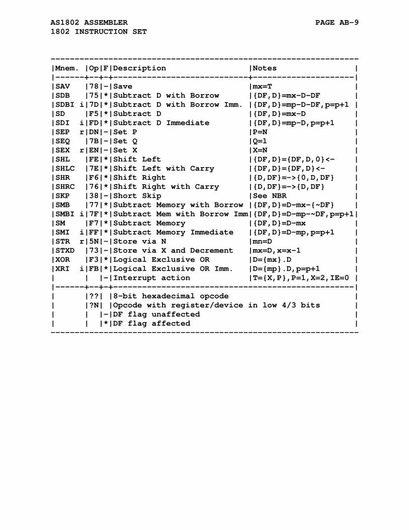
AS1802 ASSEMBLER PAGE AB-9 1802 INSTRUCTION SET
---------------------------------------------------------------- |Mnem. |Op|F|Description |Notes | |------+--+-+----------------------------+---------------------| |SAV |78|-|Save |mx=T | |SDB |75|*|Subtract D with Borrow |{DF,D}=mx-D-DF | |SDBI i|7D|*|Subtract D with Borrow Imm. |{DF,D}=mp-D-DF,p=p+1 | |SD |F5|*|Subtract D |{DF,D}=mx-D | |SDI i|FD|*|Subtract D Immediate |{DF,D}=mp-D,p=p+1 | |SEP r|DN|-|Set P |P=N | |SEQ |7B|-|Set Q |Q=1 | |SEX r|EN|-|Set X |X=N | |SHL |FE|*|Shift Left |{DF,D}={DF,D,0}<- | |SHLC |7E|*|Shift Left with Carry |{DF,D}={DF,D}<- | |SHR |F6|*|Shift Right |{D,DF}=->{0,D,DF} | |SHRC |76|*|Shift Right with Carry |{D,DF}=->{D,DF} | |SKP |38|-|Short Skip |See NBR | |SMB |77|*|Subtract Memory with Borrow |{DF,D}=D-mx-{~DF} | |SMBI i|7F|*|Subtract Mem with Borrow Imm|{DF,D}=D-mp-~DF,p=p+1| |SM |F7|*|Subtract Memory |{DF,D}=D-mx | |SMI i|FF|*|Subtract Memory Immediate |{DF,D}=D-mp,p=p+1 | |STR r|5N|-|Store via N |mn=D | |STXD |73|-|Store via X and Decrement |mx=D,x=x-1 | |XOR |F3|*|Logical Exclusive OR |D={mx}.D | |XRI i|FB|*|Logical Exclusive OR Imm. |D={mp}.D,p=p+1 | | | |-|Interrupt action |T={X,P},P=1,X=2,IE=0 | |------+--+-+--------------------------------------------------| | |??| |8-bit hexadecimal opcode | | |?N| |Opcode with register/device in low 4/3 bits | | | |-|DF flag unaffected | | | |*|DF flag affected | ----------------------------------------------------------------
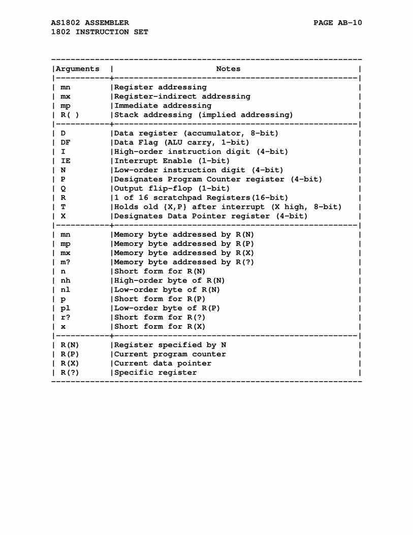
AS1802 ASSEMBLER PAGE AB-10 1802 INSTRUCTION SET
---------------------------------------------------------------- |Arguments | Notes | |-----------+--------------------------------------------------| | mn |Register addressing | | mx |Register-indirect addressing | | mp |Immediate addressing | | R( ) |Stack addressing (implied addressing) | |-----------+--------------------------------------------------| | D |Data register (accumulator, 8-bit) | | DF |Data Flag (ALU carry, 1-bit) | | I |High-order instruction digit (4-bit) | | IE |Interrupt Enable (1-bit) | | N |Low-order instruction digit (4-bit) | | P |Designates Program Counter register (4-bit) | | Q |Output flip-flop (1-bit) | | R |1 of 16 scratchpad Registers(16-bit) | | T |Holds old {X,P} after interrupt (X high, 8-bit) | | X |Designates Data Pointer register (4-bit) | |-----------+--------------------------------------------------| | mn |Memory byte addressed by R(N) | | mp |Memory byte addressed by R(P) | | mx |Memory byte addressed by R(X) | | m? |Memory byte addressed by R(?) | | n |Short form for R(N) | | nh |High-order byte of R(N) | | nl |Low-order byte of R(N) | | p |Short form for R(P) | | pl |Low-order byte of R(P) | | r? |Short form for R(?) | | x |Short form for R(X) | |-----------+--------------------------------------------------| | R(N) |Register specified by N | | R(P) |Current program counter | | R(X) |Current data pointer | | R(?) |Specific register | ----------------------------------------------------------------

AS1802 ASSEMBLER PAGE AB-11 1802 INSTRUCTION SET
---------------------------------------------------------------- |Arguments | Notes | |-----------+--------------------------------------------------| | a |Address expression | | d |Device number (1-7) | | i |Immediate expression | | n |Expression | | r |Register (hex digit or an R followed by hex digit)| |-----------+--------------------------------------------------| | + |Arithmetic addition | | - |Arithmetic subtraction | | * |Arithmetic multiplication | | / |Arithmetic division | | & |Logical AND | | ~ |Logical NOT | | v |Logical inclusive OR | | . |Logical exclusive OR | | <- |Rotate left | | -> |Rotate right | | { } |Combination of operands | | ? |Hexadecimal digit (0-F) | | --> |Input pin | | <-- |Output pin | | <--> |Input/output pin | ----------------------------------------------------------------
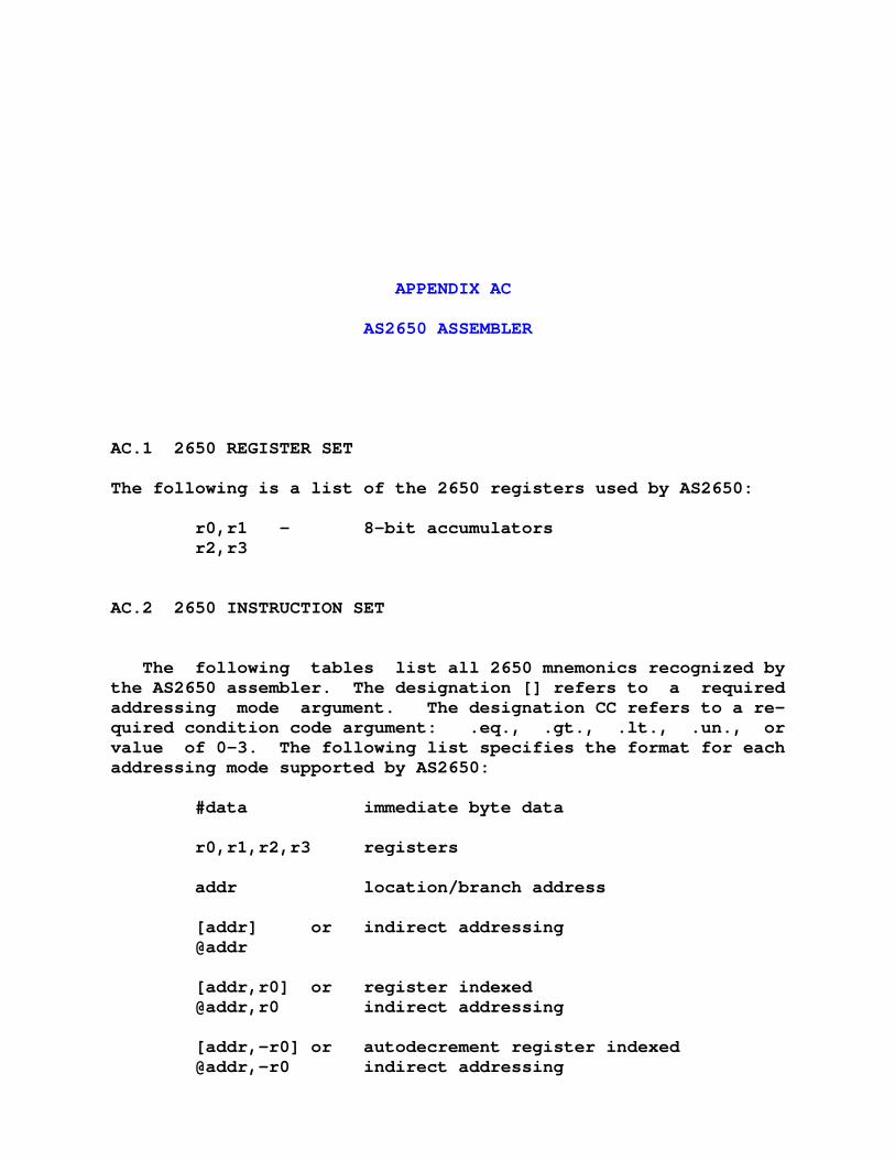
APPENDIX AC
AS2650 ASSEMBLER
AC.1 2650 REGISTER SET
The following is a list of the 2650 registers used by AS2650:
r0,r1 - 8-bit accumulators r2,r3
AC.2 2650 INSTRUCTION SET
The following tables list all 2650 mnemonics recognized by the AS2650 assembler. The designation [] refers to a required addressing mode argument. The designation CC refers to a re- quired condition code argument: .eq., .gt., .lt., .un., or value of 0-3. The following list specifies the format for each addressing mode supported by AS2650:
#data immediate byte data r0,r1,r2,r3 registers addr location/branch address [addr] or indirect addressing @addr [addr,r0] or register indexed @addr,r0 indirect addressing [addr,-r0] or autodecrement register indexed @addr,-r0 indirect addressing

AS2650 ASSEMBLER PAGE AC-2 2650 INSTRUCTION SET
[addr,r0+] or autoincrement register indexed @addr,r0+ indirect addressing .eq. CC: equal (== 0) .gt. CC: greater than (== 1) .lt. CC: less than (== 2) .un. CC: unconditional (== 3)
The terms data, label, and addr may all be expressions.
Note that not all addressing modes are valid with every in- struction, refer to the 2650 technical data for valid modes.
AC.2.1 Load / Store Instructions
lodz r lodi #data lodr [] loda [] stoz r stor [] stoa []
AC.2.2 Arithmetic / Compare Instructions
addz r addi #data addr [] adda [] subz r subi #data subr [] suba [] comz r comi #data comr [] coma [] dar r
AC.2.3 Logical / Rotate Instructions
andz r andi #data andr [] anda [] iorz r iori #data iorr [] iora [] eorz r eori #data eorr [] eora [] rrr r
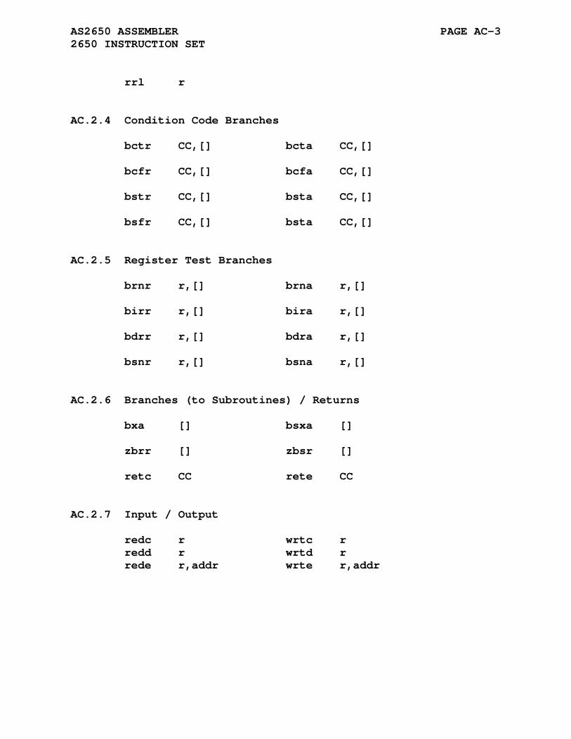
AS2650 ASSEMBLER PAGE AC-3 2650 INSTRUCTION SET
rrl r
AC.2.4 Condition Code Branches
bctr CC,[] bcta CC,[] bcfr CC,[] bcfa CC,[] bstr CC,[] bsta CC,[] bsfr CC,[] bsta CC,[]
AC.2.5 Register Test Branches
brnr r,[] brna r,[] birr r,[] bira r,[] bdrr r,[] bdra r,[] bsnr r,[] bsna r,[]
AC.2.6 Branches (to Subroutines) / Returns
bxa [] bsxa [] zbrr [] zbsr [] retc CC rete CC
AC.2.7 Input / Output
redc r wrtc r redd r wrtd r rede r,addr wrte r,addr

AS2650 ASSEMBLER PAGE AC-4 2650 INSTRUCTION SET
AC.2.8 Miscellaneos
halt nop tmi r,#data
AC.2.9 Program Status
lpsl lpsu spsl spsu cpsl #data cpsu #data ppsl #data ppsu #data tpsl #data tpsu #data

APPENDIX AD
AS430 ASSEMBLER
AD.1 MPS430 REGISTER SET
The following is a list of the MPS430 registers used by AS430:
Sixteen 16-bit registers provide adddress, data, and special functions: pc / r0 - program counter sp / r1 - stack pointer sr / r2 - status register cg1 / r2 - constant generator 1 cg2 / r3 - constant generator 2 r4 - working register r4 r5 - working register r5 ... r14 - working register r14 r15 - working register r15
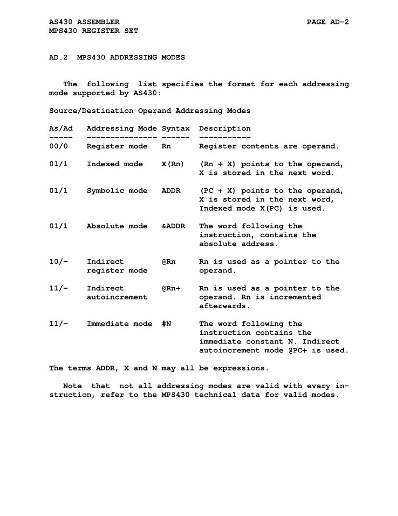
AS430 ASSEMBLER PAGE AD-2 MPS430 REGISTER SET
AD.2 MPS430 ADDRESSING MODES
The following list specifies the format for each addressing mode supported by AS430:
Source/Destination Operand Addressing Modes As/Ad Addressing Mode Syntax Description ----- --------------- ------ ----------- 00/0 Register mode Rn Register contents are operand. 01/1 Indexed mode X(Rn) (Rn + X) points to the operand, X is stored in the next word. 01/1 Symbolic mode ADDR (PC + X) points to the operand, X is stored in the next word, Indexed mode X(PC) is used. 01/1 Absolute mode &ADDR The word following the instruction, contains the absolute address. 10/- Indirect @Rn Rn is used as a pointer to the register mode operand. 11/- Indirect @Rn+ Rn is used as a pointer to the autoincrement operand. Rn is incremented afterwards. 11/- Immediate mode #N The word following the instruction contains the immediate constant N. Indirect autoincrement mode @PC+ is used.
The terms ADDR, X and N may all be expressions.
Note that not all addressing modes are valid with every in- struction, refer to the MPS430 technical data for valid modes.
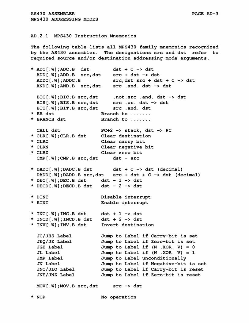
AS430 ASSEMBLER PAGE AD-3 MPS430 ADDRESSING MODES
AD.2.1 MPS430 Instruction Mnemonics
The following table lists all MPS430 family mnemonics recognized by the AS430 assembler. The designations src and dst refer to required source and/or destination addressing mode arguments.
* ADC[.W];ADC.B dst dst + C -> dst ADD[.W];ADD.B src,dst src + dst -> dst ADDC[.W];ADDC.B src,dst src + dst + C -> dst AND[.W];AND.B src,dst src .and. dst -> dst BIC[.W];BIC.B src,dst .not.src .and. dst -> dst BIS[.W];BIS.B src,dst src .or. dst -> dst BIT[.W];BIT.B src,dst src .and. dst * BR dst Branch to ....... * BRANCH dst Branch to ....... CALL dst PC+2 -> stack, dst -> PC * CLR[.W];CLR.B dst Clear destination * CLRC Clear carry bit * CLRN Clear negative bit * CLRZ Clear zero bit CMP[.W];CMP.B src,dst dst - src * DADC[.W];DADC.B dst dst + C -> dst (decimal) DADD[.W];DADD.B src,dst src + dst + C -> dst (decimal) * DEC[.W];DEC.B dst dst - 1 -> dst * DECD[.W];DECD.B dst dst - 2 -> dst * DINT Disable interrupt * EINT Enable interrupt * INC[.W];INC.B dst dst + 1 -> dst * INCD[.W];INCD.B dst dst + 2 -> dst * INV[.W];INV.B dst Invert destination JC/JHS Label Jump to Label if Carry-bit is set JEQ/JZ Label Jump to Label if Zero-bit is set JGE Label Jump to Label if (N .XOR. V) = 0 JL Label Jump to Label if (N .XOR. V) = 1 JMP Label Jump to Label unconditionally JN Label Jump to Label if Negative-bit is set JNC/JLO Label Jump to Label if Carry-bit is reset JNE/JNZ Label Jump to Label if Zero-bit is reset MOV[.W];MOV.B src,dst src -> dst * NOP No operation

AS430 ASSEMBLER PAGE AD-4 MPS430 ADDRESSING MODES
* POP[.W];POP.B dst Item from stack, SP+2 -> SP PUSH[.W];PUSH.B src SP - 2 -> SP, src -> @SP RETI Return from interrupt TOS -> SR, SP + 2 -> SP TOS -> PC, SP + 2 -> SZP * RET Return from subroutine TOS -> PC, SP + 2 -> SP * RLA[.W];RLA.B dst Rotate left arithmetically * RLC[.W];RLC.B dst Rotate left through carry RRA[.W];RRA.B dst MSB -> MSB . ....LSB -> C RRC[.W];RRC.B dst C -> MSB . ......LSB -> C * SBC[.W];SBC.B dst Subtract carry from destination * SETC Set carry bit * SETN Set negative bit * SETZ Set zero bit SUB[.W];SUB.B src,dst dst + .not.src + 1 -> dst SUBC[.W];SUBC.B src,dst dst + .not.src + C -> dst SBB[.W];SBB.B src,dst dst + .not.src + C -> dst SWPB dst swap bytes SXT dst Bit7 -> Bit8 ........ Bit15 * TST[.W];TST.B dst Test destination XOR[.W];XOR.B src,dst src .xor. dst -> dst Note: Asterisked Instructions Asterisked (*) instructions are emulated. They are replaced with coreinstructions by the assembler.

APPENDIX AE
AS6100 ASSEMBLER
AE.1 6100 MACHINE DESCRIPTION
The IM6100 (Intersil) and HM6100 (Harris) microprocessors are 12-bit word addressable machines having three 12-bit program ac- cessible registers and one single bit register. These are the Accumulator (AC), MQ Register (MQ), Program Counter (PC), and the Link (L) respectively.
The 6100 is basically a clone of the Digital Equipment Cor- poration PDP-8E minicomputer architecture. This architecture predates all microprocessors and labeled the bits from 0 (the most significant) to 11 (the least significant) rather than from least to most significant. The actual labelling is arbitrary and the as6100 assembler uses the now more common labelling.
The output generated from the assembler/linker is two bytes per word ordered as MSB then LSB with the upper 4 bits of the MSB always zero.
AE.2 ASSEMBLER SPECIFIC DIRECTIVES
Because the 6100 microprocessor has no concept of bytes several of the cross assembler directives have their operation changed to reflect the 12-Bit nature of the microprocessor.
These are: .byte (.db and .fcb are aliases) output an 8-Bit value into a 12-bit word .word (.dw and .fdb are aliases)
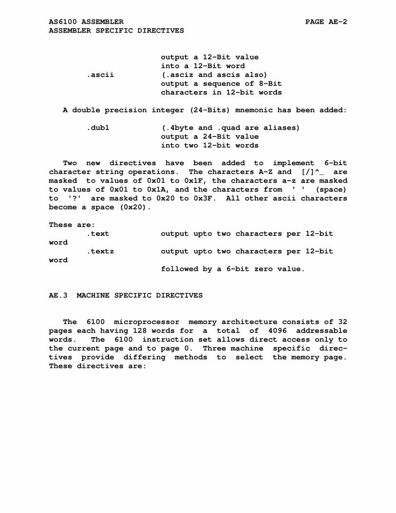
AS6100 ASSEMBLER PAGE AE-2 ASSEMBLER SPECIFIC DIRECTIVES
output a 12-Bit value into a 12-Bit word .ascii (.asciz and ascis also) output a sequence of 8-Bit characters in 12-bit words
A double precision integer (24-Bits) mnemonic has been added:
.dubl (.4byte and .quad are aliases) output a 24-Bit value into two 12-bit words
Two new directives have been added to implement 6-bit character string operations. The characters A-Z and [/]^_ are masked to values of 0x01 to 0x1F, the characters a-z are masked to values of 0x01 to 0x1A, and the characters from ' ' (space) to '?' are masked to 0x20 to 0x3F. All other ascii characters become a space (0x20).
These are: .text output upto two characters per 12-bit word .textz output upto two characters per 12-bit word followed by a 6-bit zero value.
AE.3 MACHINE SPECIFIC DIRECTIVES
The 6100 microprocessor memory architecture consists of 32 pages each having 128 words for a total of 4096 addressable words. The 6100 instruction set allows direct access only to the current page and to page 0. Three machine specific direc- tives provide differing methods to select the memory page. These directives are:
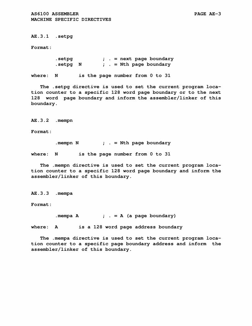
AS6100 ASSEMBLER PAGE AE-3 MACHINE SPECIFIC DIRECTIVES
AE.3.1 .setpg
Format:
.setpg ; . = next page boundary .setpg N ; . = Nth page boundary where: N is the page number from 0 to 31
The .setpg directive is used to set the current program loca- tion counter to a specific 128 word page boundary or to the next 128 word page boundary and inform the assembler/linker of this boundary.
AE.3.2 .mempn
Format:
.mempn N ; . = Nth page boundary where: N is the page number from 0 to 31
The .mempn directive is used to set the current program loca- tion counter to a specific 128 word page boundary and inform the assembler/linker of this boundary.
AE.3.3 .mempa
Format:
.mempa A ; . = A (a page boundary) where: A is a 128 word page address boundary
The .mempa directive is used to set the current program loca- tion counter to a specific page boundary address and inform the assembler/linker of this boundary.

AS6100 ASSEMBLER PAGE AE-4 6100 INSTRUCTION SET
AE.4 6100 INSTRUCTION SET
The following tables list all 6100 family mnemonics recog- nized by the AS6100 assembler. The instruction set is described in 3 major groupings: Basic Instructions, Operate Microinstruc- tions, and IOT Instructions.
AE.4.1 Basic Instructions
The basic instructions are:
and Logical AND tad Binary ADD isz Increment and skip if zero dca Deposit and clear AC jms Jump to subroutine jmp Jump
These instructions have two paging addressing modes:
addr current page address *addr page 0 address
which can be combined with an indirect mode signified by an i argument or enclosing brackets []:
i addr indirect current page [addr] i *addr indirect page 0 [*addr] or *[addr]
The 6100 implements an auto-increment mode when accessing ad- dresses 0x08 - 0x0F in page 0 by incrementing the contents of the location before using the value as an address.
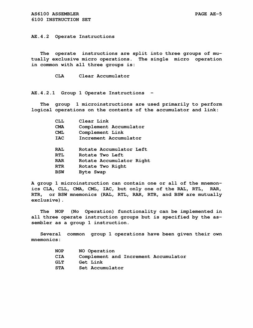
AS6100 ASSEMBLER PAGE AE-5 6100 INSTRUCTION SET
AE.4.2 Operate Instructions
The operate instructions are split into three groups of mu- tually exclusive micro operations. The single micro operation in common with all three groups is:
CLA Clear Accumulator
AE.4.2.1 Group 1 Operate Instructions -
The group 1 microinstructions are used primarily to perform logical operations on the contents of the accumulator and link:
CLL Clear Link CMA Complement Accumulator CML Complement Link IAC Increment Accumulator RAL Rotate Accumulator Left RTL Rotate Two Left RAR Rotate Accumulator Right RTR Rotate Two Right BSW Byte Swap
A group 1 microinstruction can contain one or all of the mnemon- ics CLA, CLL, CMA, CML, IAC, but only one of the RAL, RTL, RAR, RTR, or BSW mnemonics (RAL, RTL, RAR, RTR, and BSW are mutually exclusive).
The NOP (No Operation) functionality can be implemented in all three operate instruction groups but is specified by the as- sembler as a group 1 instruction.
Several common group 1 operations have been given their own mnemonics:
NOP NO Operation CIA Complement and Increment Accumulator GLT Get Link STA Set Accumulator

AS6100 ASSEMBLER PAGE AE-6 6100 INSTRUCTION SET
AE.4.2.2 Group 2 Operate Instructions -
The group 2 microinstructions are used primarily to test the contents of the accumulator and/or link and then conditionally skip the next sequential instruction:
HLT Halt OSR Or With Switch Register SKP Skip SNL Skip On Non-Zero Link SZL Skip On Zero Link SZA Skip On Zero Accumulator SNA Skip On Non-Zero Accumulator SMA Skip On Minus Accumulator SPA Skip On Plus Accumulator
A group 2 microinstruction can contain one or all of the mnemon- ics CLA, HLT, OSR, but only one of the SKP, SNL, SZL, SZA, SNA, SMA, or SPA mnemonics (SKP, SNL, SZL, SZA, SNA, SMA, and SPA are mutually exclusive).
One common group 2 operation has been given its own mnemonic:
LAS Load Accumulator With Switch Register
AE.4.2.3 Group 3 Operate Instructions -
The group 3 microinstructions perform logical operations on the contents of AC and MQ.
MQL MQ Register Load MQA MQ Register Into Accumulator
A group 3 microinstruction can contain one or all of the mnemon- ics CLA, MQL, and MQA.
Several common group 3 operations have been given their own mnemonics:
SWP Swap Accumulator and MQ Register CAM Clear Accumulator and MQ Register ACL Clear Accumulator and Load MQ Register into Accumulator

AS6100 ASSEMBLER PAGE AE-7 6100 INSTRUCTION SET
AE.4.2.4 Group Errors -
The 6100 assembler has three additional error codes which oc- cur when the group 1, 2, or 3 operations are mixed. The error code will be <1>, <2>, or <3> based upon the first group type encountered followed by any other type of group operation. The CLA operation is valid with all groups and does not cause an er- ror code to be generated.
AE.4.3 Input/Output (IOT) Instructions
The input/output transfer instructions are used to control the operation of peripherals and transfer data between peri- pherals and the 6100 microprocessor. Of the lower 9 bits of the instruction used for device selection and control typically the 3 LSBs are the I/O operation bits and the remaining 6 bits select the peripheral device.
IOT DEV,CMND where DEV is the device select code and CMND is the command code.
Specifying a device select code of zero in the IOT instruction allows the user program to control the interrupt mechanism of the 6100 microprocessor. These instructions are:
SKON Skip If Interrupt On ION Interrupt Turn On IOF Interrupt Turn Off SRQ Skip If Int Request GTF GetFlags RTF Return Flags SGT Defined By Device Logic CAF Clear All Flags
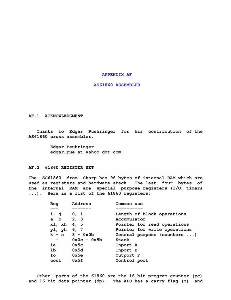
APPENDIX AF
AS61860 ASSEMBLER
AF.1 ACKNOWLEDGMENT
Thanks to Edgar Puehringer for his contribution of the AS61860 cross assembler.
Edgar Peuhringer edgar_pue at yahoo dot com
AF.2 61860 REGISTER SET
The SC61860 from Sharp has 96 bytes of internal RAM which are used as registers and hardware stack. The last four bytes of the internal RAM are special purpose registers (I/O, timers ...). Here is a list of the 61860 registers:
Reg Address Common use --- ------- ---------- i, j 0, 1 Length of block operations a, b 2, 3 Accumulator xl, xh 4, 5 Pointer for read operations yl, yh 6, 7 Pointer for write operations k - n 8 - 0x0b General purpose (counters ...) - 0x0c - 0x5b Stack ia 0x5c Inport A ib 0x5d Inport B fo 0x5e Outport F cout 0x5f Control port
Other parts of the 61860 are the 16 bit program counter (pc) and 16 bit data pointer (dp). The ALU has a carry flag (c) and
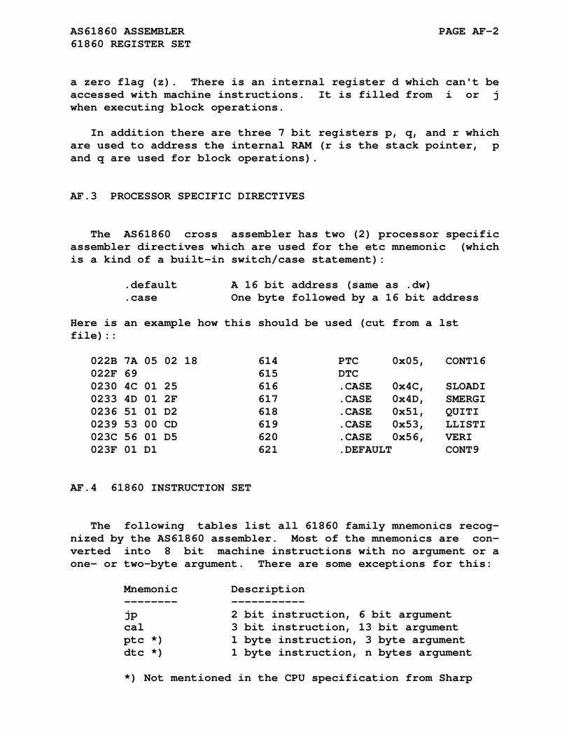
AS61860 ASSEMBLER PAGE AF-2 61860 REGISTER SET
a zero flag (z). There is an internal register d which can't be accessed with machine instructions. It is filled from i or j when executing block operations.
In addition there are three 7 bit registers p, q, and r which are used to address the internal RAM (r is the stack pointer, p and q are used for block operations).
AF.3 PROCESSOR SPECIFIC DIRECTIVES
The AS61860 cross assembler has two (2) processor specific assembler directives which are used for the etc mnemonic (which is a kind of a built-in switch/case statement):
.default A 16 bit address (same as .dw) .case One byte followed by a 16 bit address Here is an example how this should be used (cut from a lst file):: 022B 7A 05 02 18 614 PTC 0x05, CONT16 022F 69 615 DTC 0230 4C 01 25 616 .CASE 0x4C, SLOADI 0233 4D 01 2F 617 .CASE 0x4D, SMERGI 0236 51 01 D2 618 .CASE 0x51, QUITI 0239 53 00 CD 619 .CASE 0x53, LLISTI 023C 56 01 D5 620 .CASE 0x56, VERI 023F 01 D1 621 .DEFAULT CONT9
AF.4 61860 INSTRUCTION SET
The following tables list all 61860 family mnemonics recog- nized by the AS61860 assembler. Most of the mnemonics are con- verted into 8 bit machine instructions with no argument or a one- or two-byte argument. There are some exceptions for this:
Mnemonic Description -------- ----------- jp 2 bit instruction, 6 bit argument cal 3 bit instruction, 13 bit argument ptc *) 1 byte instruction, 3 byte argument dtc *) 1 byte instruction, n bytes argument *) Not mentioned in the CPU specification from Sharp
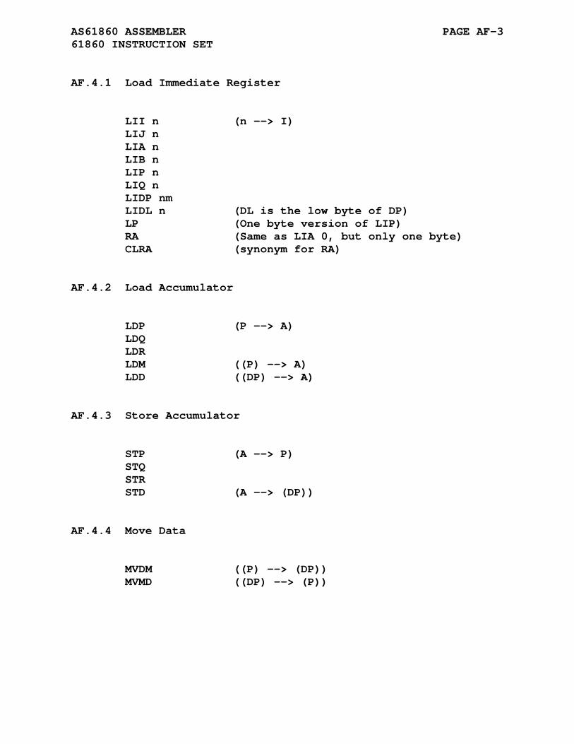
AS61860 ASSEMBLER PAGE AF-3 61860 INSTRUCTION SET
AF.4.1 Load Immediate Register
LII n (n --> I) LIJ n LIA n LIB n LIP n LIQ n LIDP nm LIDL n (DL is the low byte of DP) LP (One byte version of LIP) RA (Same as LIA 0, but only one byte) CLRA (synonym for RA)
AF.4.2 Load Accumulator
LDP (P --> A) LDQ LDR LDM ((P) --> A) LDD ((DP) --> A)
AF.4.3 Store Accumulator
STP (A --> P) STQ STR STD (A --> (DP))
AF.4.4 Move Data
MVDM ((P) --> (DP)) MVMD ((DP) --> (P))
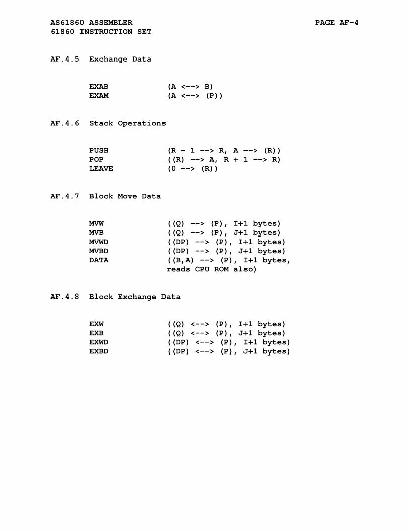
AS61860 ASSEMBLER PAGE AF-4 61860 INSTRUCTION SET
AF.4.5 Exchange Data
EXAB (A <--> B) EXAM (A <--> (P))
AF.4.6 Stack Operations
PUSH (R - 1 --> R, A --> (R)) POP ((R) --> A, R + 1 --> R) LEAVE (0 --> (R))
AF.4.7 Block Move Data
MVW ((Q) --> (P), I+1 bytes) MVB ((Q) --> (P), J+1 bytes) MVWD ((DP) --> (P), I+1 bytes) MVBD ((DP) --> (P), J+1 bytes) DATA ((B,A) --> (P), I+1 bytes, reads CPU ROM also)
AF.4.8 Block Exchange Data
EXW ((Q) <--> (P), I+1 bytes) EXB ((Q) <--> (P), J+1 bytes) EXWD ((DP) <--> (P), I+1 bytes) EXBD ((DP) <--> (P), J+1 bytes)
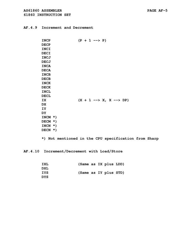
AS61860 ASSEMBLER PAGE AF-5 61860 INSTRUCTION SET
AF.4.9 Increment and Decrement
INCP (P + 1 --> P) DECP INCI DECI INCJ DECJ INCA DECA INCB DECB INCK DECK INCL DECL IX (X + 1 --> X, X --> DP) DX IY DY INCM *) DECM *) INCN *) DECN *) *) Not mentioned in the CPU specification from Sharp
AF.4.10 Increment/Decrement with Load/Store
IXL (Same as IX plus LDD) DXL IYS (Same as IY plus STD) DYS
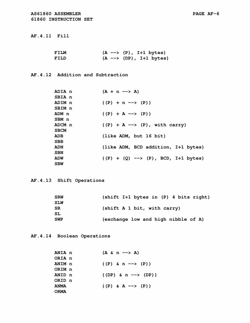
AS61860 ASSEMBLER PAGE AF-6 61860 INSTRUCTION SET
AF.4.11 Fill
FILM (A --> (P), I+1 bytes) FILD (A --> (DP), I+1 bytes)
AF.4.12 Addition and Subtraction
ADIA n (A + n --> A) SBIA n ADIM n ((P) + n --> (P)) SBIM n ADM n ((P) + A --> (P)) SBM n ADCM n ((P) + A --> (P), with carry) SBCM ADB (like ADM, but 16 bit) SBB ADN (like ADM, BCD addition, I+1 bytes) SBN ADW ((P) + (Q) --> (P), BCD, I+1 bytes) SBW
AF.4.13 Shift Operations
SRW (shift I+1 bytes in (P) 4 bits right) SLW SR (shift A 1 bit, with carry) SL SWP (exchange low and high nibble of A)
AF.4.14 Boolean Operations
ANIA n (A & n --> A) ORIA n ANIM n ((P) & n --> (P)) ORIM n ANID n ((DP) & n --> (DP)) ORID n ANMA ((P) & A --> (P)) ORMA

AS61860 ASSEMBLER PAGE AF-7 61860 INSTRUCTION SET
AF.4.15 Compare
CPIA n (A - n --> c,z) CPIM n ((P) - n --> c,z) CPMA ((P) - A --> c,z) TSIA n (A & n --> z) TSIM n ((P) & n --> z) TSID n ((DP) & n --> z) TSIP ((P) & A --> z)
AF.4.16 CPU Control
SC (Set carry) RC NOPW (no op) NOPT WAIT n (wait 6+n cycles) WAITJ (wait 5+4*I cycles) CUP (synonym for WAITJ)
AF.4.17 Absolute Jumps
JP nm JPZ nm (on zero) JPNZ nm JPC nm JPNC nm PTC/DTC (see 'Processor Specific Directives') PTJ/DTJ (synonym for PTD/DTC) CPCAL/DTLRA (synonym for PTC/DTC) CASE1/CASE2 (synonym for PTC/DTC) SETT/JST (synonym for PTC/DTC)
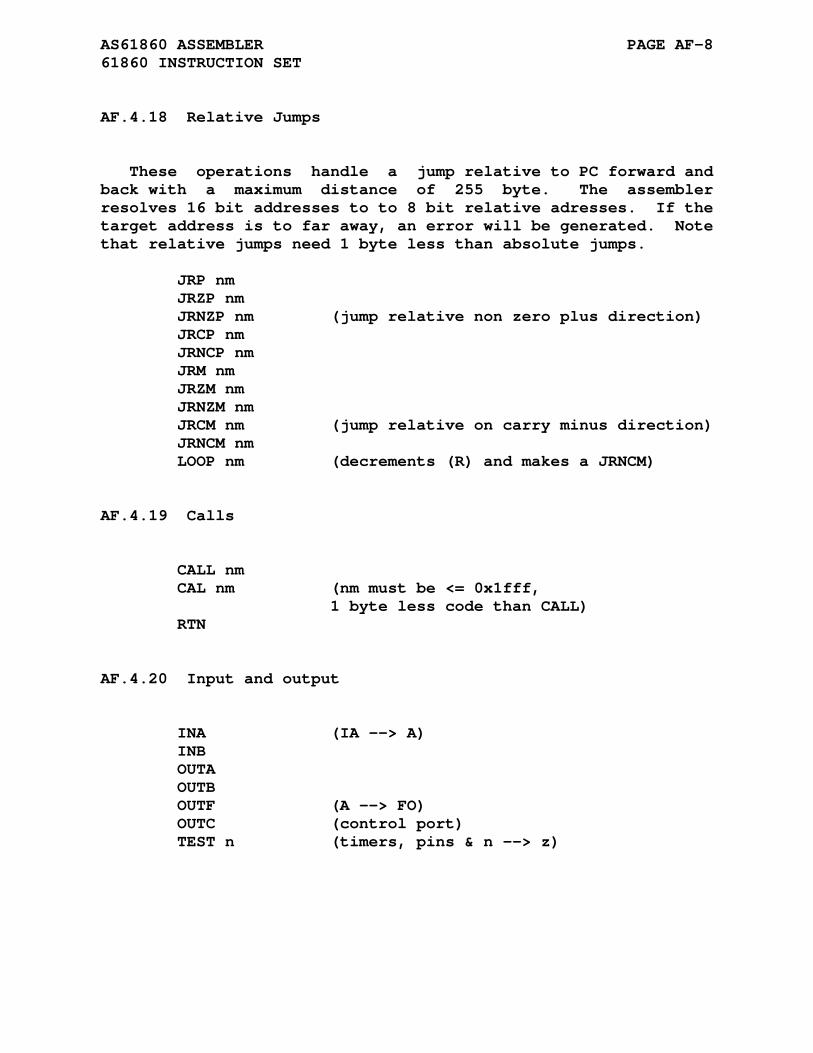
AS61860 ASSEMBLER PAGE AF-8 61860 INSTRUCTION SET
AF.4.18 Relative Jumps
These operations handle a jump relative to PC forward and back with a maximum distance of 255 byte. The assembler resolves 16 bit addresses to to 8 bit relative adresses. If the target address is to far away, an error will be generated. Note that relative jumps need 1 byte less than absolute jumps.
JRP nm JRZP nm JRNZP nm (jump relative non zero plus direction) JRCP nm JRNCP nm JRM nm JRZM nm JRNZM nm JRCM nm (jump relative on carry minus direction) JRNCM nm LOOP nm (decrements (R) and makes a JRNCM)
AF.4.19 Calls
CALL nm CAL nm (nm must be <= 0x1fff, 1 byte less code than CALL) RTN
AF.4.20 Input and output
INA (IA --> A) INB OUTA OUTB OUTF (A --> FO) OUTC (control port) TEST n (timers, pins & n --> z)

AS61860 ASSEMBLER PAGE AF-9 61860 INSTRUCTION SET
AF.4.21 Unknown Commands
READ ((PC+1) -> A) READM ((PC+1) -> (P)) WRIT (???)

APPENDIX AG
AS6500 ASSEMBLER
AG.1 ACKNOWLEDGMENT
Thanks to Marko Makela for his contribution of the AS6500 cross assembler.
Marko Makela Sillitie 10 A 01480 Vantaa Finland Internet: Marko dot Makela at Helsinki dot Fi EARN/BitNet: msmakela at finuh
Several additions and modifications were made to his code to support the following families of 6500 processors:
(1) 650X and 651X processor family (2) 65F11 and 65F12 processor family (3) 65C00/21 and 65C29 processor family (4) 65C02, 65C102, and 65C112 processor family
The instruction syntax of this cross assembler contains two peculiarities: (1) the addressing indirection is denoted by the square brackets [] and (2) the `bbrx' and `bbsx' instructions are written `bbr0 memory,label'.
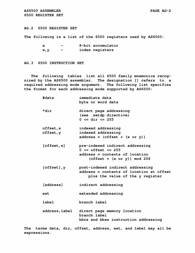
AS6500 ASSEMBLER PAGE AG-2 6500 REGISTER SET
AG.2 6500 REGISTER SET
The following is a list of the 6500 registers used by AS6500:
a - 8-bit accumulator x,y - index registers
AG.3 6500 INSTRUCTION SET
The following tables list all 6500 family mnemonics recog- nized by the AS6500 assembler. The designation [] refers to a required addressing mode argument. The following list specifies the format for each addressing mode supported by AS6500:
#data immediate data byte or word data *dir direct page addressing (see .setdp directive) 0 <= dir <= 255 offset,x indexed addressing offset,y indexed addressing address = (offset + (x or y)) [offset,x] pre-indexed indirect addressing 0 <= offset <= 255 address = contents of location (offset + (x or y)) mod 256 [offset],y post-indexed indirect addressing address = contents of location at offset plus the value of the y register [address] indirect addressing ext extended addressing label branch label address,label direct page memory location branch label bbrx and bbsx instruction addressing
The terms data, dir, offset, address, ext, and label may all be expressions.
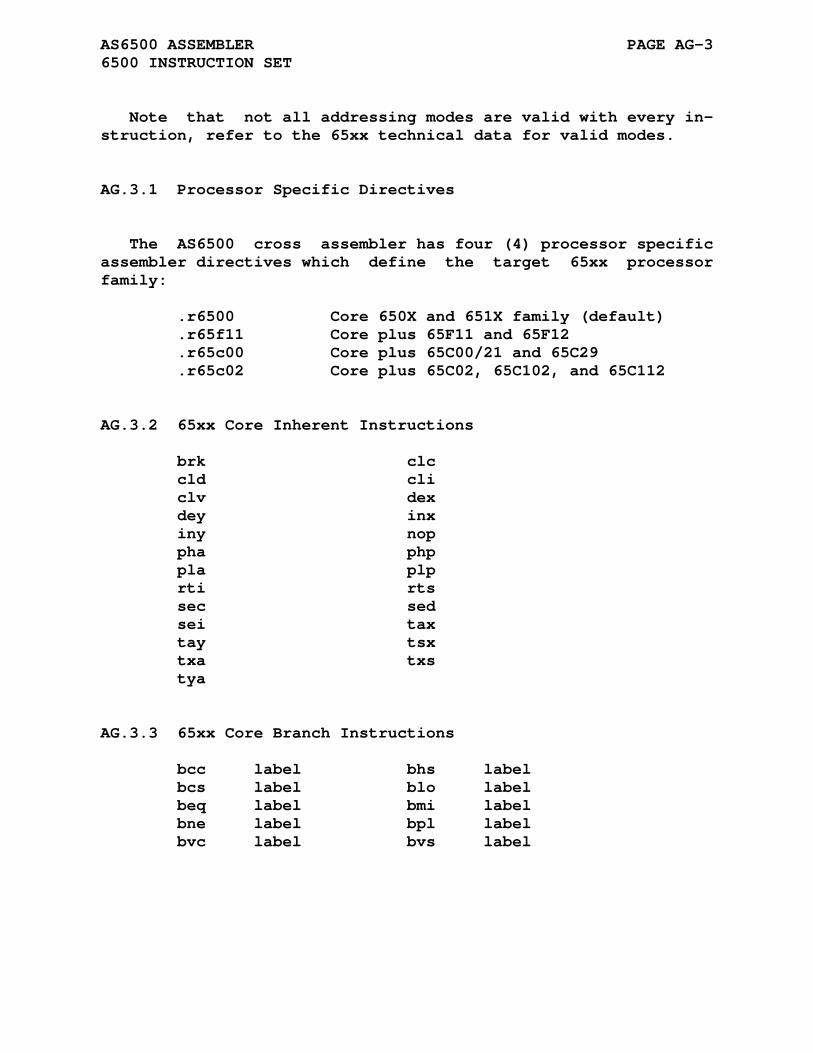
AS6500 ASSEMBLER PAGE AG-3 6500 INSTRUCTION SET
Note that not all addressing modes are valid with every in- struction, refer to the 65xx technical data for valid modes.
AG.3.1 Processor Specific Directives
The AS6500 cross assembler has four (4) processor specific assembler directives which define the target 65xx processor family:
.r6500 Core 650X and 651X family (default) .r65f11 Core plus 65F11 and 65F12 .r65c00 Core plus 65C00/21 and 65C29 .r65c02 Core plus 65C02, 65C102, and 65C112
AG.3.2 65xx Core Inherent Instructions
brk clc cld cli clv dex dey inx iny nop pha php pla plp rti rts sec sed sei tax tay tsx txa txs tya
AG.3.3 65xx Core Branch Instructions
bcc label bhs label bcs label blo label beq label bmi label bne label bpl label bvc label bvs label
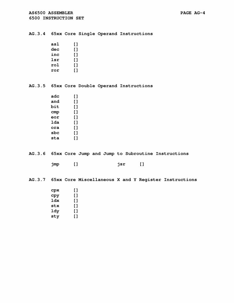
AS6500 ASSEMBLER PAGE AG-4 6500 INSTRUCTION SET
AG.3.4 65xx Core Single Operand Instructions
asl [] dec [] inc [] lsr [] rol [] ror []
AG.3.5 65xx Core Double Operand Instructions
adc [] and [] bit [] cmp [] eor [] lda [] ora [] sbc [] sta []
AG.3.6 65xx Core Jump and Jump to Subroutine Instructions
jmp [] jsr []
AG.3.7 65xx Core Miscellaneous X and Y Register Instructions
cpx [] cpy [] ldx [] stx [] ldy [] sty []
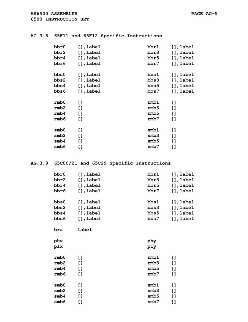
AS6500 ASSEMBLER PAGE AG-5 6500 INSTRUCTION SET
AG.3.8 65F11 and 65F12 Specific Instructions
bbr0 [],label bbr1 [],label bbr2 [],label bbr3 [],label bbr4 [],label bbr5 [],label bbr6 [],label bbr7 [],label bbs0 [],label bbs1 [],label bbs2 [],label bbs3 [],label bbs4 [],label bbs5 [],label bbs6 [],label bbs7 [],label rmb0 [] rmb1 [] rmb2 [] rmb3 [] rmb4 [] rmb5 [] rmb6 [] rmb7 [] smb0 [] smb1 [] smb2 [] smb3 [] smb4 [] smb5 [] smb6 [] smb7 []
AG.3.9 65C00/21 and 65C29 Specific Instructions
bbr0 [],label bbr1 [],label bbr2 [],label bbr3 [],label bbr4 [],label bbr5 [],label bbr6 [],label bbr7 [],label bbs0 [],label bbs1 [],label bbs2 [],label bbs3 [],label bbs4 [],label bbs5 [],label bbs6 [],label bbs7 [],label bra label phx phy plx ply rmb0 [] rmb1 [] rmb2 [] rmb3 [] rmb4 [] rmb5 [] rmb6 [] rmb7 [] smb0 [] smb1 [] smb2 [] smb3 [] smb4 [] smb5 [] smb6 [] smb7 []

AS6500 ASSEMBLER PAGE AG-6 6500 INSTRUCTION SET
AG.3.10 65C02, 65C102, and 65C112 Specific Instructions
bbr0 [],label bbr1 [],label bbr2 [],label bbr3 [],label bbr4 [],label bbr5 [],label bbr6 [],label bbr7 [],label bbs0 [],label bbs1 [],label bbs2 [],label bbs3 [],label bbs4 [],label bbs5 [],label bbs6 [],label bbs7 [],label bra label phx phy plx ply rmb0 [] rmb1 [] rmb2 [] rmb3 [] rmb4 [] rmb5 [] rmb6 [] rmb7 [] smb0 [] smb1 [] smb2 [] smb3 [] smb4 [] smb5 [] smb6 [] smb7 [] stz [] trb [] tsb []
Additional addressing modes for the following core instruc- tions are also available with the 65C02, 65C102, and 65C112 pro- cessors.
adc [] and [] cmp [] eor [] lda [] ora [] sbc [] sta [] bit [] jmp [] dec inc
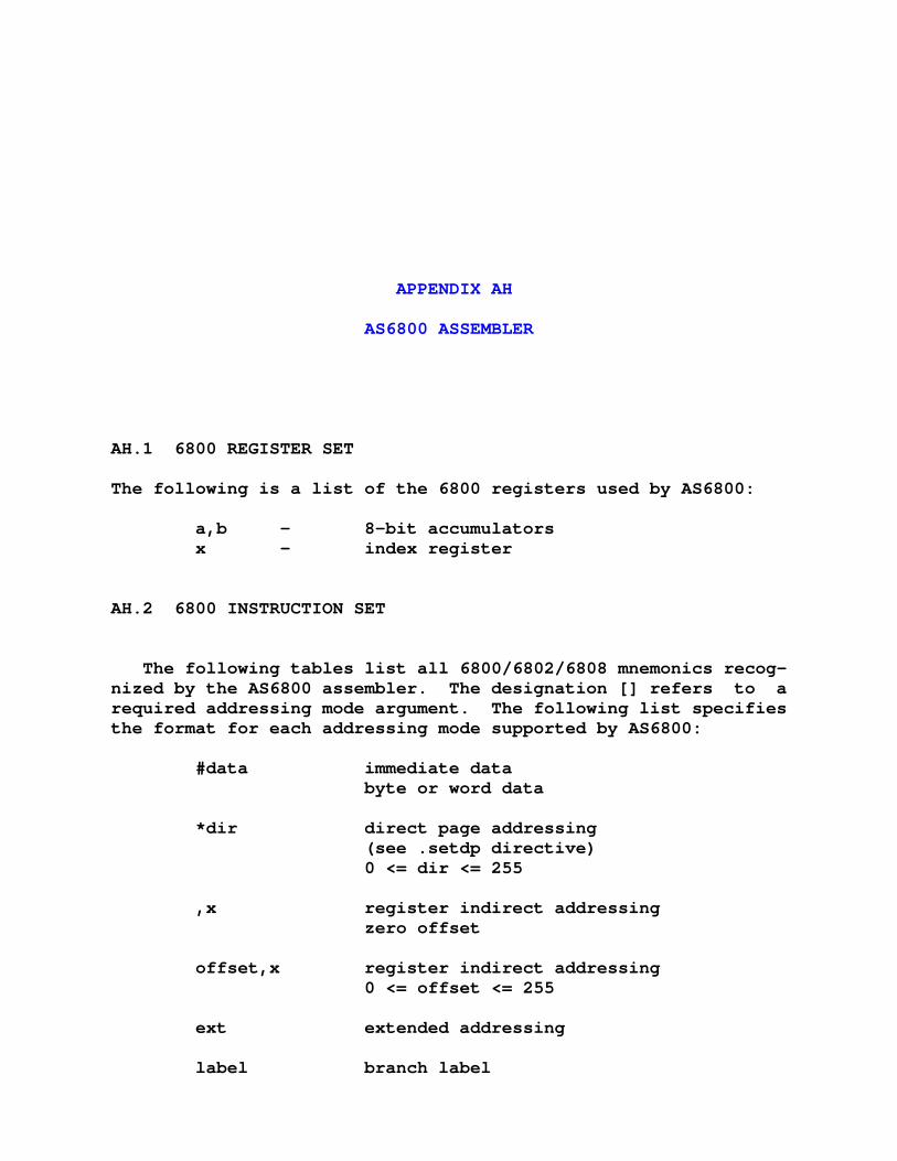
APPENDIX AH
AS6800 ASSEMBLER
AH.1 6800 REGISTER SET
The following is a list of the 6800 registers used by AS6800:
a,b - 8-bit accumulators x - index register
AH.2 6800 INSTRUCTION SET
The following tables list all 6800/6802/6808 mnemonics recog- nized by the AS6800 assembler. The designation [] refers to a required addressing mode argument. The following list specifies the format for each addressing mode supported by AS6800:
#data immediate data byte or word data *dir direct page addressing (see .setdp directive) 0 <= dir <= 255 ,x register indirect addressing zero offset offset,x register indirect addressing 0 <= offset <= 255 ext extended addressing label branch label

AS6800 ASSEMBLER PAGE AH-2 6800 INSTRUCTION SET
The terms data, dir, offset, ext, and label may all be expres- sions.
Note that not all addressing modes are valid with every in- struction, refer to the 6800 technical data for valid modes.
AH.2.1 Inherent Instructions
aba cba clc cli clv daa des dex ins inx nop rti rts sba sec sei sev swi tab tap tba tpa tsx txs wai psha pshb psh a psh b pula pulb pul a pul b
AH.2.2 Branch Instructions
bra label bhi label bls label bcc label bhs label bcs label blo label bne label beq label bvc label bvs label bpl label bmi label bge label blt label bgt label ble label bsr label
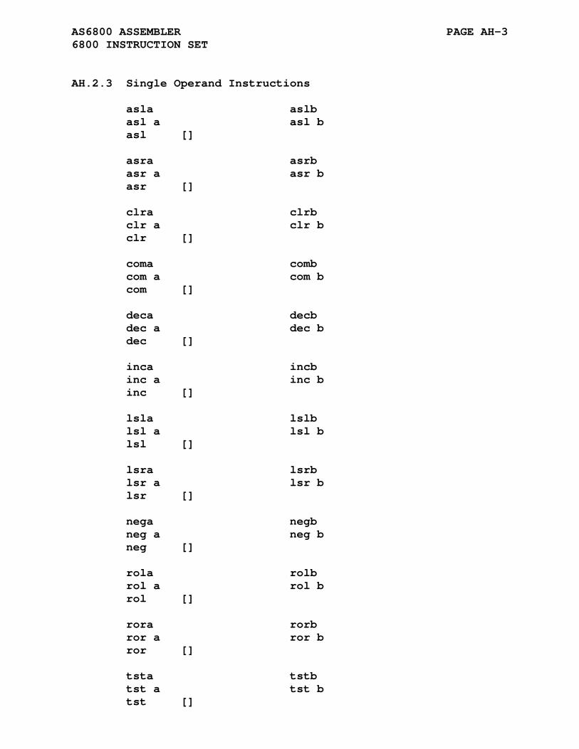
AS6800 ASSEMBLER PAGE AH-3 6800 INSTRUCTION SET
AH.2.3 Single Operand Instructions
asla aslb asl a asl b asl [] asra asrb asr a asr b asr [] clra clrb clr a clr b clr [] coma comb com a com b com [] deca decb dec a dec b dec [] inca incb inc a inc b inc [] lsla lslb lsl a lsl b lsl [] lsra lsrb lsr a lsr b lsr [] nega negb neg a neg b neg [] rola rolb rol a rol b rol [] rora rorb ror a ror b ror [] tsta tstb tst a tst b tst []
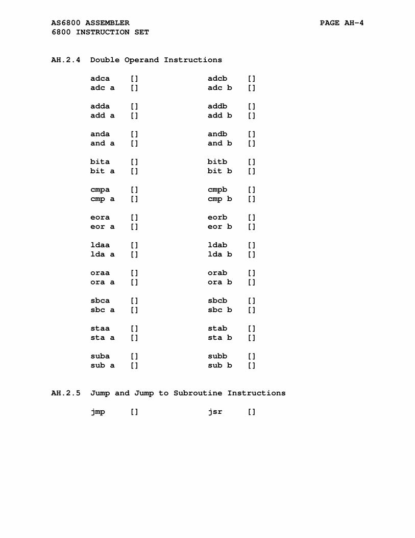
AS6800 ASSEMBLER PAGE AH-4 6800 INSTRUCTION SET
AH.2.4 Double Operand Instructions
adca [] adcb [] adc a [] adc b [] adda [] addb [] add a [] add b [] anda [] andb [] and a [] and b [] bita [] bitb [] bit a [] bit b [] cmpa [] cmpb [] cmp a [] cmp b [] eora [] eorb [] eor a [] eor b [] ldaa [] ldab [] lda a [] lda b [] oraa [] orab [] ora a [] ora b [] sbca [] sbcb [] sbc a [] sbc b [] staa [] stab [] sta a [] sta b [] suba [] subb [] sub a [] sub b []
AH.2.5 Jump and Jump to Subroutine Instructions
jmp [] jsr []

AS6800 ASSEMBLER PAGE AH-5 6800 INSTRUCTION SET
AH.2.6 Long Register Instructions
cpx [] lds [] sts [] ldx [] stx []
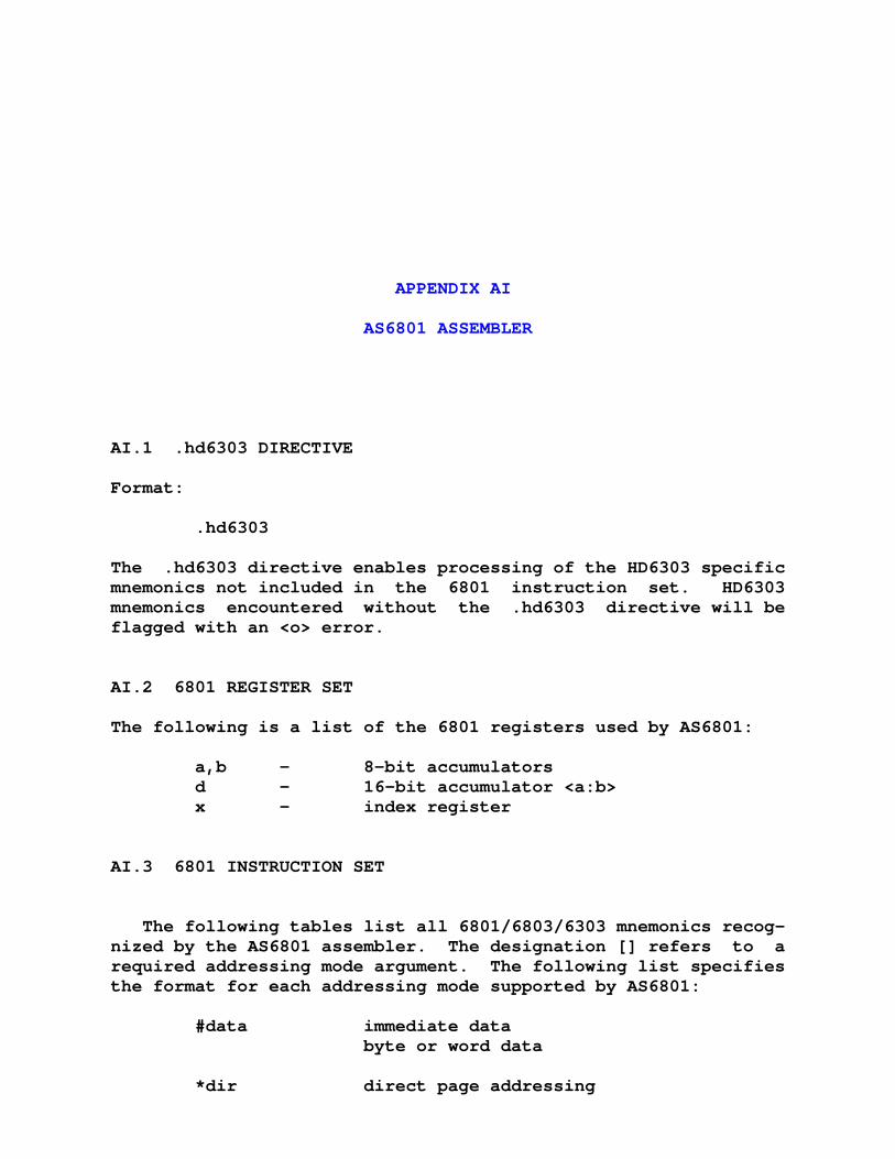
APPENDIX AI
AS6801 ASSEMBLER
AI.1 .hd6303 DIRECTIVE
Format:
.hd6303
The .hd6303 directive enables processing of the HD6303 specific mnemonics not included in the 6801 instruction set. HD6303 mnemonics encountered without the .hd6303 directive will be flagged with an <o> error.
AI.2 6801 REGISTER SET
The following is a list of the 6801 registers used by AS6801:
a,b - 8-bit accumulators d - 16-bit accumulator <a:b> x - index register
AI.3 6801 INSTRUCTION SET
The following tables list all 6801/6803/6303 mnemonics recog- nized by the AS6801 assembler. The designation [] refers to a required addressing mode argument. The following list specifies the format for each addressing mode supported by AS6801:
#data immediate data byte or word data *dir direct page addressing
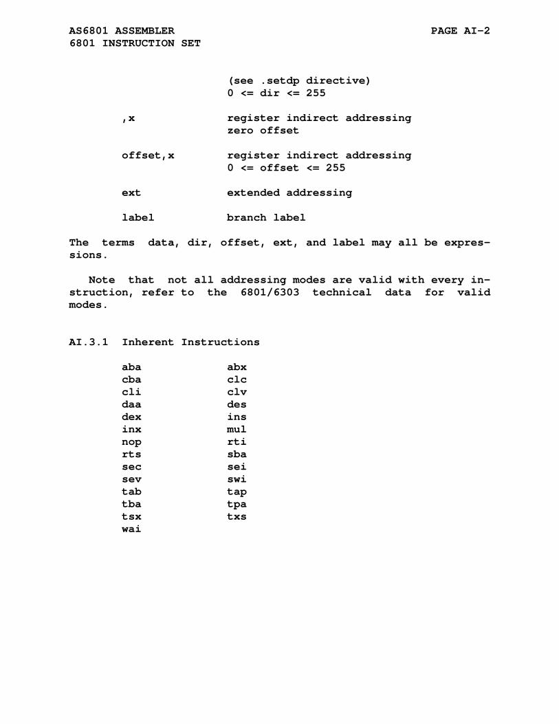
AS6801 ASSEMBLER PAGE AI-2 6801 INSTRUCTION SET
(see .setdp directive) 0 <= dir <= 255 ,x register indirect addressing zero offset offset,x register indirect addressing 0 <= offset <= 255 ext extended addressing label branch label
The terms data, dir, offset, ext, and label may all be expres- sions.
Note that not all addressing modes are valid with every in- struction, refer to the 6801/6303 technical data for valid modes.
AI.3.1 Inherent Instructions
aba abx cba clc cli clv daa des dex ins inx mul nop rti rts sba sec sei sev swi tab tap tba tpa tsx txs wai
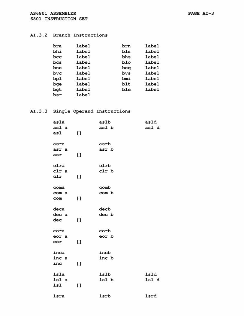
AS6801 ASSEMBLER PAGE AI-3 6801 INSTRUCTION SET
AI.3.2 Branch Instructions
bra label brn label bhi label bls label bcc label bhs label bcs label blo label bne label beq label bvc label bvs label bpl label bmi label bge label blt label bgt label ble label bsr label
AI.3.3 Single Operand Instructions
asla aslb asld asl a asl b asl d asl [] asra asrb asr a asr b asr [] clra clrb clr a clr b clr [] coma comb com a com b com [] deca decb dec a dec b dec [] eora eorb eor a eor b eor [] inca incb inc a inc b inc [] lsla lslb lsld lsl a lsl b lsl d lsl [] lsra lsrb lsrd

AS6801 ASSEMBLER PAGE AI-4 6801 INSTRUCTION SET
lsr a lsr b lsr d lsr [] nega negb neg a neg b neg [] psha pshb pshx psh a psh b psh x pula pulb pulx pul a pul b pul x rola rolb rol a rol b rol [] rora rorb ror a ror b ror [] tsta tstb tst a tst b tst []
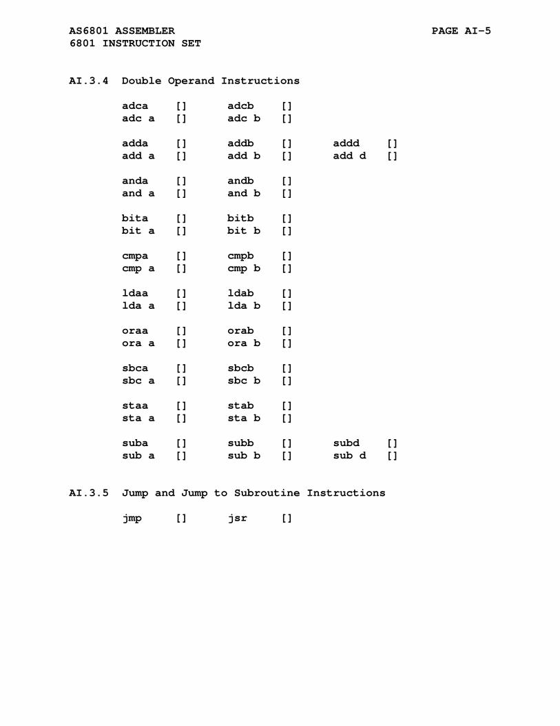
AS6801 ASSEMBLER PAGE AI-5 6801 INSTRUCTION SET
AI.3.4 Double Operand Instructions
adca [] adcb [] adc a [] adc b [] adda [] addb [] addd [] add a [] add b [] add d [] anda [] andb [] and a [] and b [] bita [] bitb [] bit a [] bit b [] cmpa [] cmpb [] cmp a [] cmp b [] ldaa [] ldab [] lda a [] lda b [] oraa [] orab [] ora a [] ora b [] sbca [] sbcb [] sbc a [] sbc b [] staa [] stab [] sta a [] sta b [] suba [] subb [] subd [] sub a [] sub b [] sub d []
AI.3.5 Jump and Jump to Subroutine Instructions
jmp [] jsr []
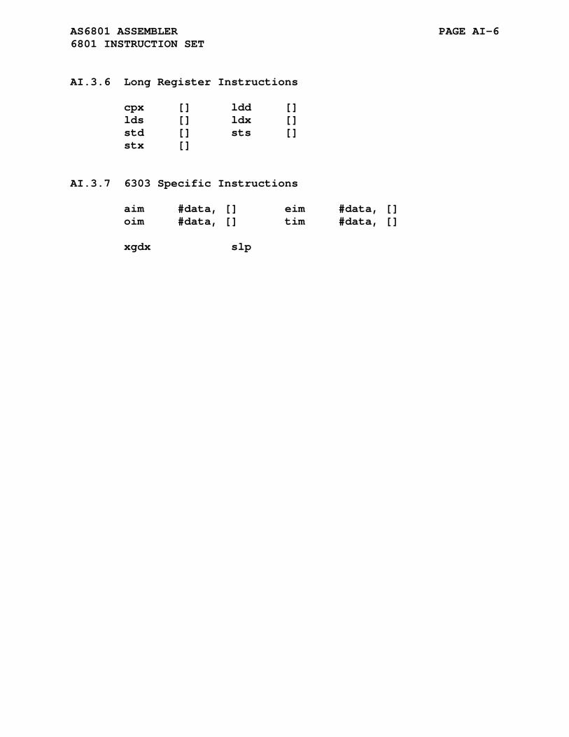
AS6801 ASSEMBLER PAGE AI-6 6801 INSTRUCTION SET
AI.3.6 Long Register Instructions
cpx [] ldd [] lds [] ldx [] std [] sts [] stx []
AI.3.7 6303 Specific Instructions
aim #data, [] eim #data, [] oim #data, [] tim #data, [] xgdx slp
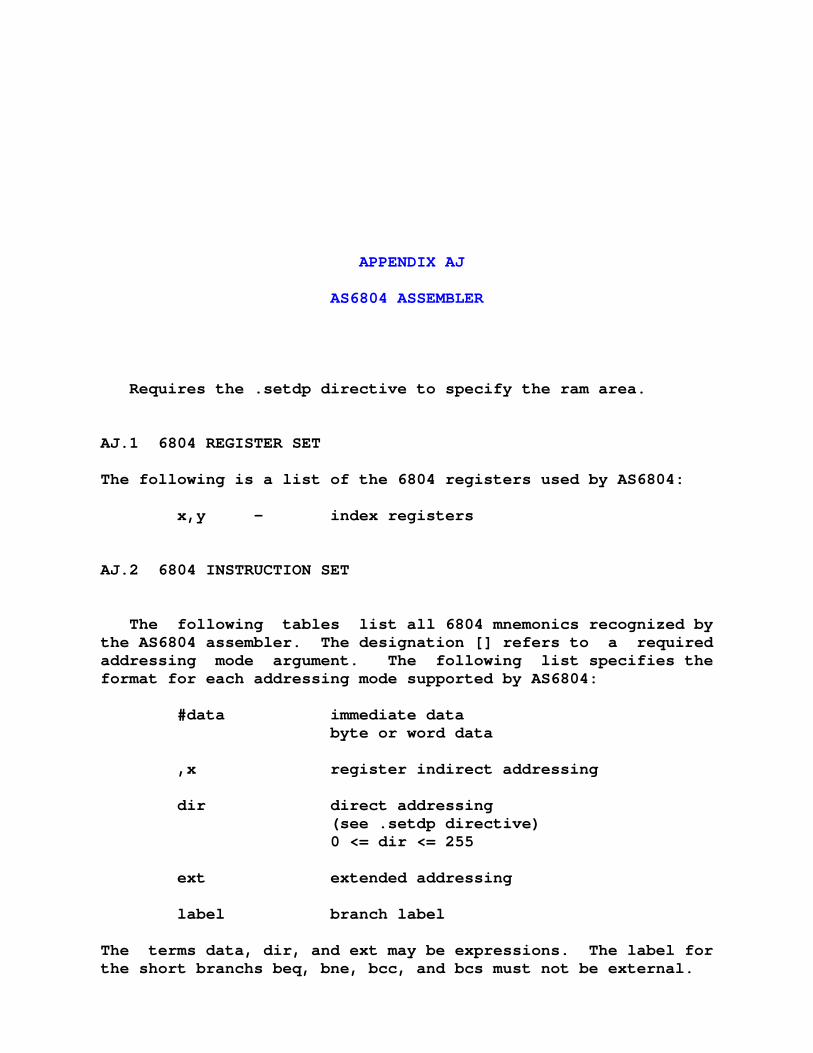
APPENDIX AJ
AS6804 ASSEMBLER
Requires the .setdp directive to specify the ram area.
AJ.1 6804 REGISTER SET
The following is a list of the 6804 registers used by AS6804:
x,y - index registers
AJ.2 6804 INSTRUCTION SET
The following tables list all 6804 mnemonics recognized by the AS6804 assembler. The designation [] refers to a required addressing mode argument. The following list specifies the format for each addressing mode supported by AS6804:
#data immediate data byte or word data ,x register indirect addressing dir direct addressing (see .setdp directive) 0 <= dir <= 255 ext extended addressing label branch label
The terms data, dir, and ext may be expressions. The label for the short branchs beq, bne, bcc, and bcs must not be external.
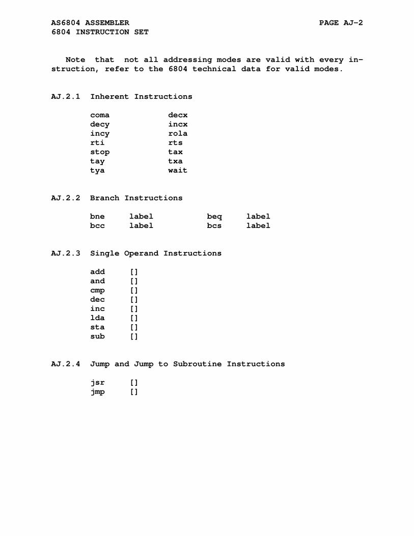
AS6804 ASSEMBLER PAGE AJ-2 6804 INSTRUCTION SET
Note that not all addressing modes are valid with every in- struction, refer to the 6804 technical data for valid modes.
AJ.2.1 Inherent Instructions
coma decx decy incx incy rola rti rts stop tax tay txa tya wait
AJ.2.2 Branch Instructions
bne label beq label bcc label bcs label
AJ.2.3 Single Operand Instructions
add [] and [] cmp [] dec [] inc [] lda [] sta [] sub []
AJ.2.4 Jump and Jump to Subroutine Instructions
jsr [] jmp []
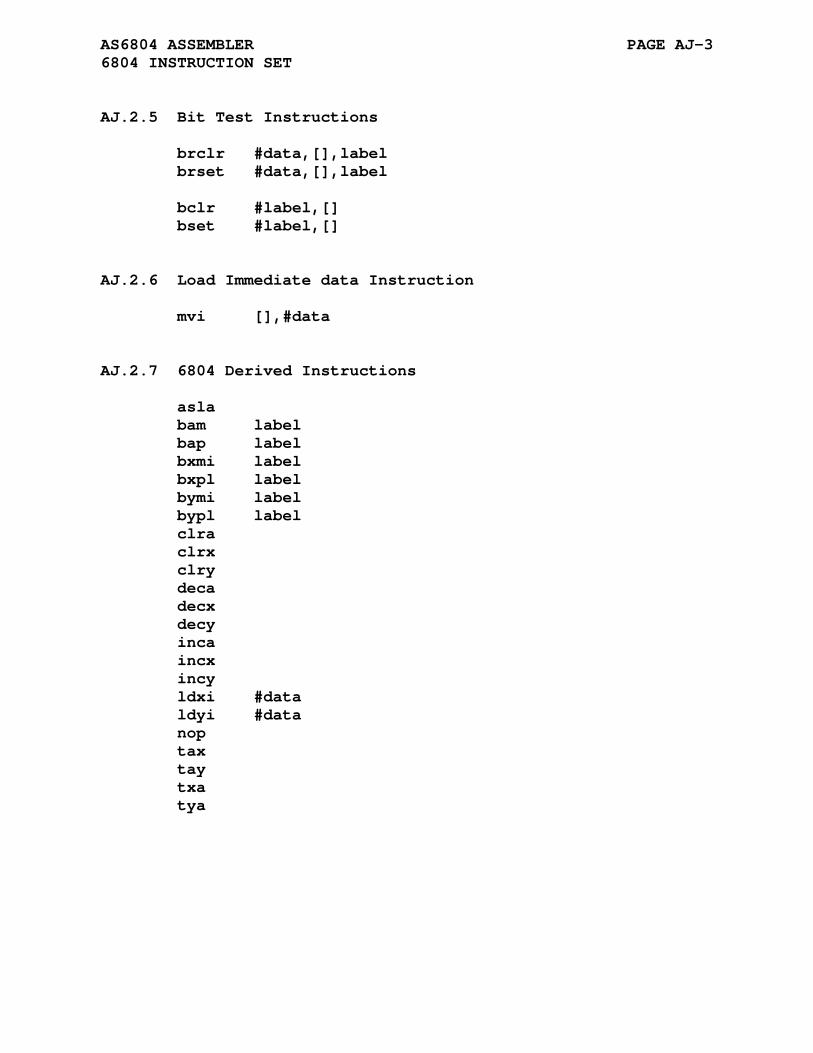
AS6804 ASSEMBLER PAGE AJ-3 6804 INSTRUCTION SET
AJ.2.5 Bit Test Instructions
brclr #data,[],label brset #data,[],label bclr #label,[] bset #label,[]
AJ.2.6 Load Immediate data Instruction
mvi [],#data
AJ.2.7 6804 Derived Instructions
asla bam label bap label bxmi label bxpl label bymi label bypl label clra clrx clry deca decx decy inca incx incy ldxi #data ldyi #data nop tax tay txa tya
APPENDIX AK
AS68(HC)05 ASSEMBLER
AK.1 .6805 DIRECTIVE
Format:
.6805
The .6805 directive selects the MC6805 specific cycles count to be output.
AK.2 .hc05 DIRECTIVE
Format:
.hc05
The .hc05 directive selects the MC68HC05/146805 specific cycles count to be output.
AK.3 THE .__.CPU. VARIABLE
The value of the pre-defined symbol '.__.CPU.' corresponds to the selected processor type. The default value is 0 which cor- responds to the default processor type. The following table lists the processor types and associated values for the ASZ80 assembler:
Processor Type .__.CPU. Value -------------- -------------- .6805 0 .hc05 1
AS68(HC)05 ASSEMBLER PAGE AK-2 THE .__.CPU. VARIABLE
The variable '.__.CPU.' is by default defined as local and will not be output to the created .rel file. The assembler com- mand line options -g or -a will not cause the local symbol to be output to the created .rel file.
The assembler .globl directive may be used to change the variable type to global causing its definition to be output to the .rel file. The inclusion of the definition of the variable '.__.CPU.' might be a useful means of validating that seperately assembled files have been compiled for the same processor type. The linker will report an error for variables with multiple non equal definitions.
AK.4 6805 REGISTER SET
The following is a list of the 6805 registers used by AS6805:
a - 8-bit accumulator x - index register
AK.5 6805 INSTRUCTION SET
The following tables list all 6805 mnemonics recognized by the AS6805 assembler. The designation [] refers to a required addressing mode argument. The following list specifies the format for each addressing mode supported by AS6805:
#data immediate data byte or word data *dir direct page addressing (see .setdp directive) 0 <= dir <= 255 ,x register indirect addressing zero offset offset,x register indirect addressing 0 <= offset <= 255 --- byte mode 256 <= offset <= 65535 --- word mode (an externally defined offset uses the word mode) ext extended addressing
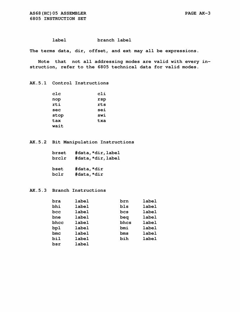
AS68(HC)05 ASSEMBLER PAGE AK-3 6805 INSTRUCTION SET
label branch label
The terms data, dir, offset, and ext may all be expressions.
Note that not all addressing modes are valid with every in- struction, refer to the 6805 technical data for valid modes.
AK.5.1 Control Instructions
clc cli nop rsp rti rts sec sei stop swi tax txa wait
AK.5.2 Bit Manipulation Instructions
brset #data,*dir,label brclr #data,*dir,label bset #data,*dir bclr #data,*dir
AK.5.3 Branch Instructions
bra label brn label bhi label bls label bcc label bcs label bne label beq label bhcc label bhcs label bpl label bmi label bmc label bms label bil label bih label bsr label
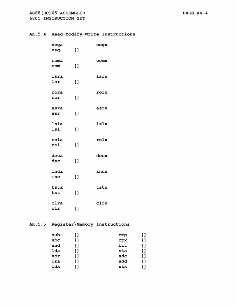
AS68(HC)05 ASSEMBLER PAGE AK-4 6805 INSTRUCTION SET
AK.5.4 Read-Modify-Write Instructions
nega negx neg [] coma comx com [] lsra lsrx lsr [] rora rorx ror [] asra asrx asr [] lsla lslx lsl [] rola rolx rol [] deca decx dec [] inca incx inc [] tsta tstx tst [] clra clrx clr []
AK.5.5 Register\Memory Instructions
sub [] cmp [] sbc [] cpx [] and [] bit [] lda [] sta [] eor [] adc [] ora [] add [] ldx [] stx []
AS68(HC)05 ASSEMBLER PAGE AK-5 6805 INSTRUCTION SET
AK.5.6 Jump and Jump to Subroutine Instructions
jmp [] jsr []
APPENDIX AL
AS68(HC[S])08 ASSEMBLER
AL.1 PROCESSOR SPECIFIC DIRECTIVES
The MC68HC(S)08 processor is a superset of the MC6805 proces- sors. The AS6808 assembler supports the HC08, HCS08, 6805, and HC05 cores.
AL.1.1 .hc08 Directive
Format:
.hc08
The .hc08 directive enables processing of only the HC08 specific mnemonics. 6805/HC05/HCS08 mnemonics encountered without the .hc08 directive will be flagged with an <o> error.
The .hc08 directive also selects the HC08 specific cycles count to be output.
AS68(HC[S])08 ASSEMBLER PAGE AL-2 PROCESSOR SPECIFIC DIRECTIVES
AL.1.2 .hcs08 Directive
Format:
.hcs08
The .hcs08 directive enables processing of the HCS08 specific mnemonics.
The .hcs08 directive also selects the HCS08 specific cycles count to be output.
AL.1.3 .6805 Directive
Format:
.6805
The .6805 directive enables processing of only the 6805/HC05 specific mnemonics. HC08/HCS08 mnemonics encountered without the .hc08/.hcs08 directives will be flagged with an <o> error.
The .6805 directive also selects the MC6805 specific cycles count to be output.
AL.1.4 .hc05 Directive
Format:
.hc05
The .hc05 directive enables processing of only the 6805/HC05 specific mnemonics. HC08/HCS08 mnemonics encountered without the .hc08/.hcs08 directives will be flagged with an <o> error.
The .hc05 directive also selects the MC68HC05/146805 specific cycles count to be output.
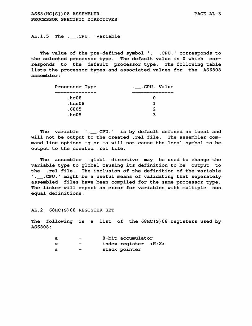
AS68(HC[S])08 ASSEMBLER PAGE AL-3 PROCESSOR SPECIFIC DIRECTIVES
AL.1.5 The .__.CPU. Variable
The value of the pre-defined symbol '.__.CPU.' corresponds to the selected processor type. The default value is 0 which cor- responds to the default processor type. The following table lists the processor types and associated values for the AS6808 assembler:
Processor Type .__.CPU. Value -------------- -------------- .hc08 0 .hcs08 1 .6805 2 .hc05 3
The variable '.__.CPU.' is by default defined as local and will not be output to the created .rel file. The assembler com- mand line options -g or -a will not cause the local symbol to be output to the created .rel file.
The assembler .globl directive may be used to change the variable type to global causing its definition to be output to the .rel file. The inclusion of the definition of the variable '.__.CPU.' might be a useful means of validating that seperately assembled files have been compiled for the same processor type. The linker will report an error for variables with multiple non equal definitions.
AL.2 68HC(S)08 REGISTER SET
The following is a list of the 68HC(S)08 registers used by AS6808:
a - 8-bit accumulator x - index register <H:X> s - stack pointer
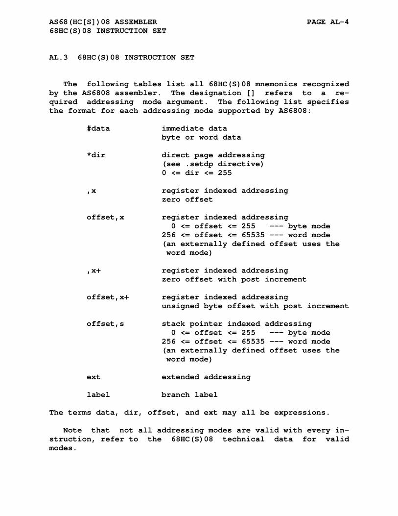
AS68(HC[S])08 ASSEMBLER PAGE AL-4 68HC(S)08 INSTRUCTION SET
AL.3 68HC(S)08 INSTRUCTION SET
The following tables list all 68HC(S)08 mnemonics recognized by the AS6808 assembler. The designation [] refers to a re- quired addressing mode argument. The following list specifies the format for each addressing mode supported by AS6808:
#data immediate data byte or word data *dir direct page addressing (see .setdp directive) 0 <= dir <= 255 ,x register indexed addressing zero offset offset,x register indexed addressing 0 <= offset <= 255 --- byte mode 256 <= offset <= 65535 --- word mode (an externally defined offset uses the word mode) ,x+ register indexed addressing zero offset with post increment offset,x+ register indexed addressing unsigned byte offset with post increment offset,s stack pointer indexed addressing 0 <= offset <= 255 --- byte mode 256 <= offset <= 65535 --- word mode (an externally defined offset uses the word mode) ext extended addressing label branch label
The terms data, dir, offset, and ext may all be expressions.
Note that not all addressing modes are valid with every in- struction, refer to the 68HC(S)08 technical data for valid modes.
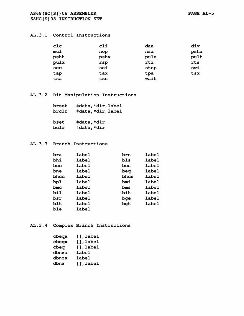
AS68(HC[S])08 ASSEMBLER PAGE AL-5 68HC(S)08 INSTRUCTION SET
AL.3.1 Control Instructions
clc cli daa div mul nop nsa psha pshh pshx pula pulh pulx rsp rti rts sec sei stop swi tap tax tpa tsx txa txs wait
AL.3.2 Bit Manipulation Instructions
brset #data,*dir,label brclr #data,*dir,label bset #data,*dir bclr #data,*dir
AL.3.3 Branch Instructions
bra label brn label bhi label bls label bcc label bcs label bne label beq label bhcc label bhcs label bpl label bmi label bmc label bms label bil label bih label bsr label bge label blt label bgt label ble label
AL.3.4 Complex Branch Instructions
cbeqa [],label cbeqx [],label cbeq [],label dbnza label dbnzx label dbnz [],label

AS68(HC[S])08 ASSEMBLER PAGE AL-6 68HC(S)08 INSTRUCTION SET
AL.3.5 Read-Modify-Write Instructions
nega negx neg [] coma comx com [] lsra lsrx lsr [] rora rorx ror [] asra asrx asr [] asla aslx asl [] lsla lslx lsl [] rola rolx rol [] deca decx dec [] inca incx inc [] tsta tstx tst [] clra clrx clr [] clrh aix #data ais #data
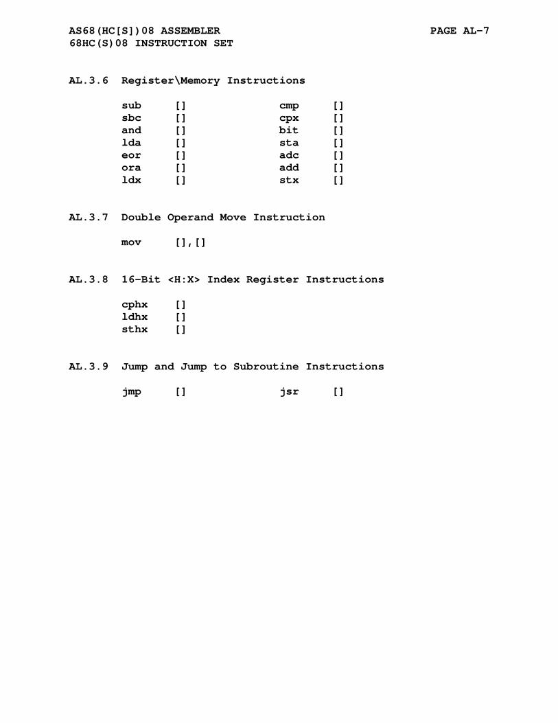
AS68(HC[S])08 ASSEMBLER PAGE AL-7 68HC(S)08 INSTRUCTION SET
AL.3.6 Register\Memory Instructions
sub [] cmp [] sbc [] cpx [] and [] bit [] lda [] sta [] eor [] adc [] ora [] add [] ldx [] stx []
AL.3.7 Double Operand Move Instruction
mov [],[]
AL.3.8 16-Bit <H:X> Index Register Instructions
cphx [] ldhx [] sthx []
AL.3.9 Jump and Jump to Subroutine Instructions
jmp [] jsr []
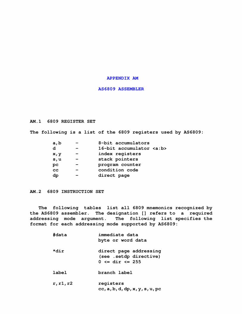
APPENDIX AM
AS6809 ASSEMBLER
AM.1 6809 REGISTER SET
The following is a list of the 6809 registers used by AS6809:
a,b - 8-bit accumulators d - 16-bit accumulator <a:b> x,y - index registers s,u - stack pointers pc - program counter cc - condition code dp - direct page
AM.2 6809 INSTRUCTION SET
The following tables list all 6809 mnemonics recognized by the AS6809 assembler. The designation [] refers to a required addressing mode argument. The following list specifies the format for each addressing mode supported by AS6809:
#data immediate data byte or word data *dir direct page addressing (see .setdp directive) 0 <= dir <= 255 label branch label r,r1,r2 registers cc,a,b,d,dp,x,y,s,u,pc
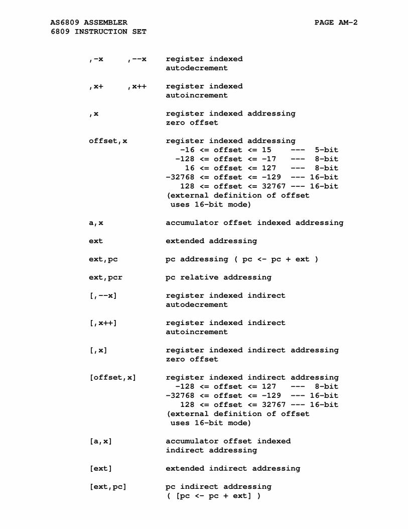
AS6809 ASSEMBLER PAGE AM-2 6809 INSTRUCTION SET
,-x ,--x register indexed autodecrement ,x+ ,x++ register indexed autoincrement ,x register indexed addressing zero offset offset,x register indexed addressing -16 <= offset <= 15 --- 5-bit -128 <= offset <= -17 --- 8-bit 16 <= offset <= 127 --- 8-bit -32768 <= offset <= -129 --- 16-bit 128 <= offset <= 32767 --- 16-bit (external definition of offset uses 16-bit mode) a,x accumulator offset indexed addressing ext extended addressing ext,pc pc addressing ( pc <- pc + ext ) ext,pcr pc relative addressing [,--x] register indexed indirect autodecrement [,x++] register indexed indirect autoincrement [,x] register indexed indirect addressing zero offset [offset,x] register indexed indirect addressing -128 <= offset <= 127 --- 8-bit -32768 <= offset <= -129 --- 16-bit 128 <= offset <= 32767 --- 16-bit (external definition of offset uses 16-bit mode) [a,x] accumulator offset indexed indirect addressing [ext] extended indirect addressing [ext,pc] pc indirect addressing ( [pc <- pc + ext] )
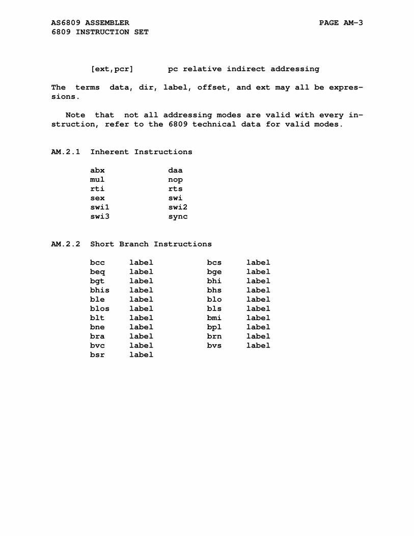
AS6809 ASSEMBLER PAGE AM-3 6809 INSTRUCTION SET
[ext,pcr] pc relative indirect addressing
The terms data, dir, label, offset, and ext may all be expres- sions.
Note that not all addressing modes are valid with every in- struction, refer to the 6809 technical data for valid modes.
AM.2.1 Inherent Instructions
abx daa mul nop rti rts sex swi swi1 swi2 swi3 sync
AM.2.2 Short Branch Instructions
bcc label bcs label beq label bge label bgt label bhi label bhis label bhs label ble label blo label blos label bls label blt label bmi label bne label bpl label bra label brn label bvc label bvs label bsr label
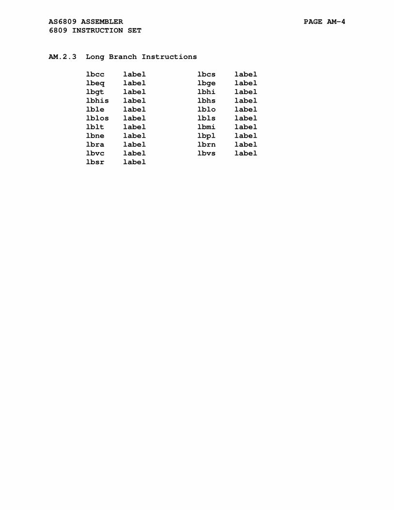
AS6809 ASSEMBLER PAGE AM-4 6809 INSTRUCTION SET
AM.2.3 Long Branch Instructions
lbcc label lbcs label lbeq label lbge label lbgt label lbhi label lbhis label lbhs label lble label lblo label lblos label lbls label lblt label lbmi label lbne label lbpl label lbra label lbrn label lbvc label lbvs label lbsr label
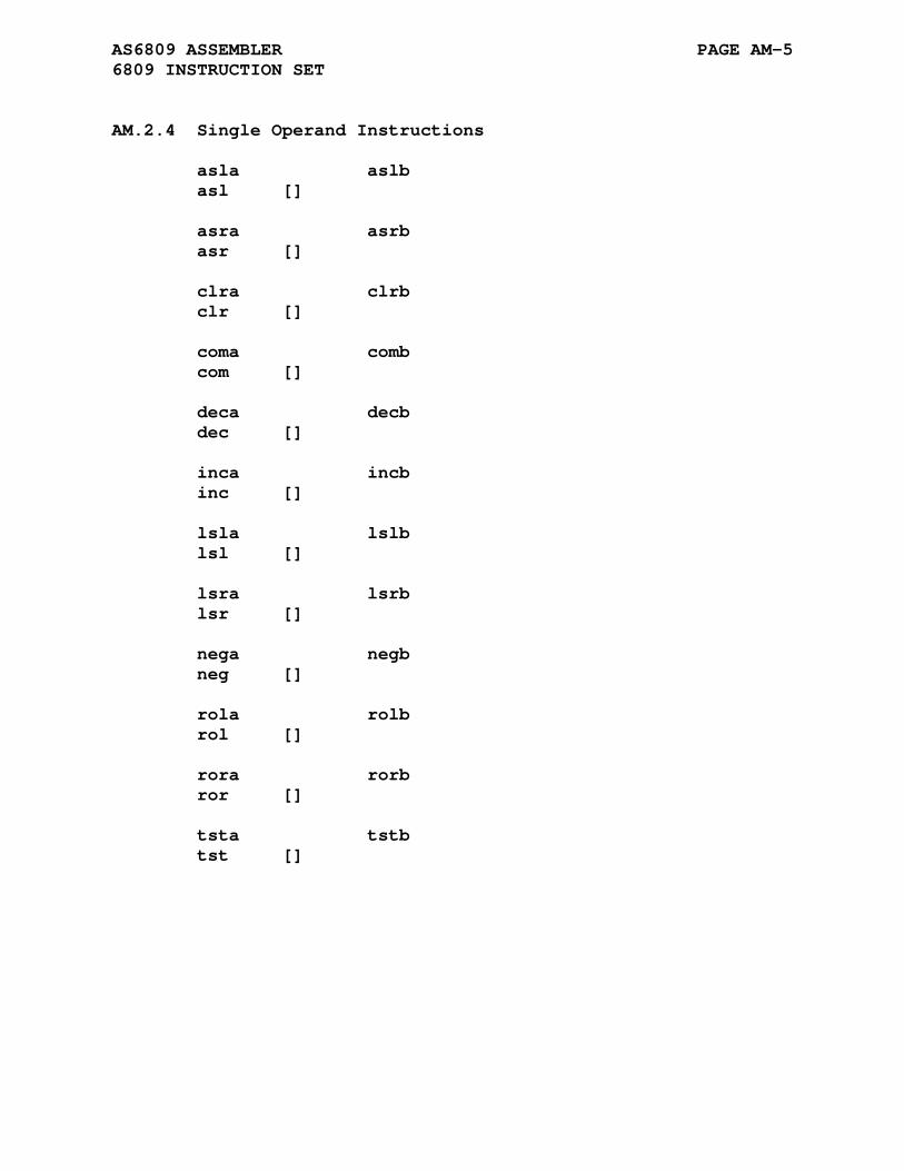
AS6809 ASSEMBLER PAGE AM-5 6809 INSTRUCTION SET
AM.2.4 Single Operand Instructions
asla aslb asl [] asra asrb asr [] clra clrb clr [] coma comb com [] deca decb dec [] inca incb inc [] lsla lslb lsl [] lsra lsrb lsr [] nega negb neg [] rola rolb rol [] rora rorb ror [] tsta tstb tst []

AS6809 ASSEMBLER PAGE AM-6 6809 INSTRUCTION SET
AM.2.5 Double Operand Instructions
adca [] adcb [] adda [] addb [] anda [] andb [] bita [] bitb [] cmpa [] cmpb [] eora [] eorb [] lda [] ldb [] ora [] orb [] sbca [] sbcb [] sta [] stb [] suba [] subb []
AM.2.6 D-register Instructions
addd [] subd [] cmpd [] ldd [] std []

AS6809 ASSEMBLER PAGE AM-7 6809 INSTRUCTION SET
AM.2.7 Index/Stack Register Instructions
cmps [] cmpu [] cmpx [] cmpy [] lds [] ldu [] ldx [] ldy [] leas [] leau [] leax [] leay [] sts [] stu [] stx [] sty [] pshs r pshu r puls r pulu r
AM.2.8 Jump and Jump to Subroutine Instructions
jmp [] jsr []
AM.2.9 Register - Register Instructions
exg r1,r2 tfr r1,r2
AM.2.10 Condition Code Register Instructions
andcc #data orcc #data cwai #data
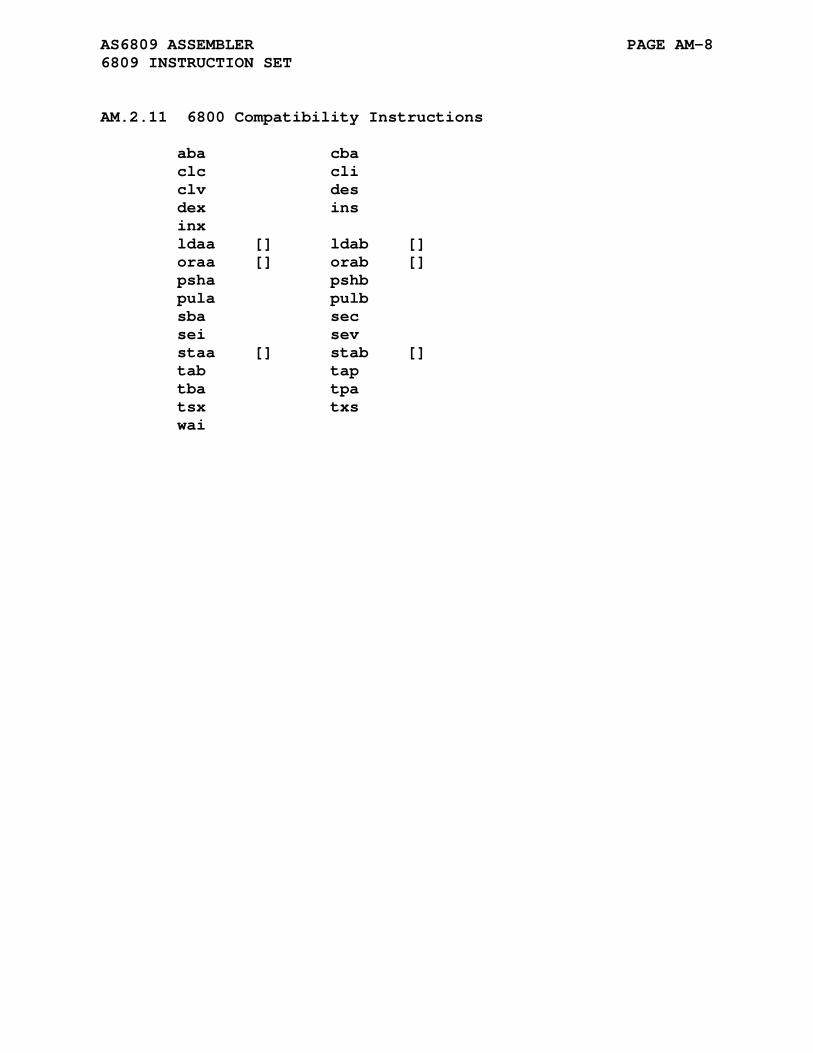
AS6809 ASSEMBLER PAGE AM-8 6809 INSTRUCTION SET
AM.2.11 6800 Compatibility Instructions
aba cba clc cli clv des dex ins inx ldaa [] ldab [] oraa [] orab [] psha pshb pula pulb sba sec sei sev staa [] stab [] tab tap tba tpa tsx txs wai
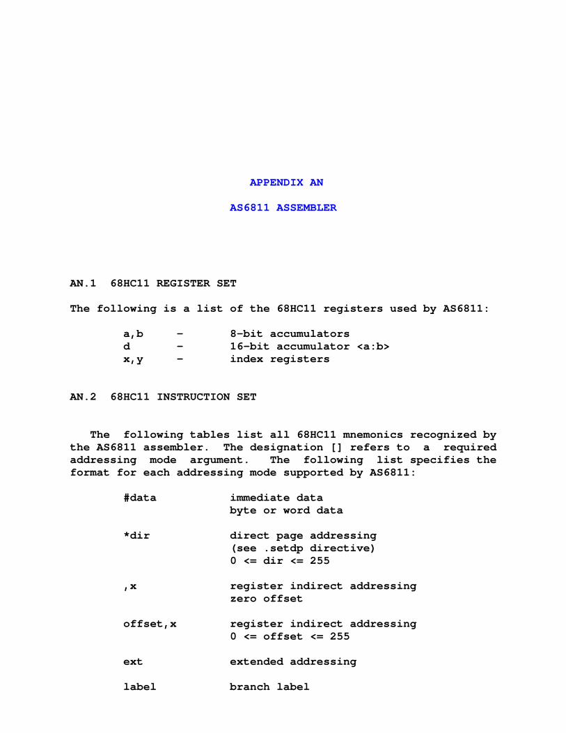
APPENDIX AN
AS6811 ASSEMBLER
AN.1 68HC11 REGISTER SET
The following is a list of the 68HC11 registers used by AS6811:
a,b - 8-bit accumulators d - 16-bit accumulator <a:b> x,y - index registers
AN.2 68HC11 INSTRUCTION SET
The following tables list all 68HC11 mnemonics recognized by the AS6811 assembler. The designation [] refers to a required addressing mode argument. The following list specifies the format for each addressing mode supported by AS6811:
#data immediate data byte or word data *dir direct page addressing (see .setdp directive) 0 <= dir <= 255 ,x register indirect addressing zero offset offset,x register indirect addressing 0 <= offset <= 255 ext extended addressing label branch label
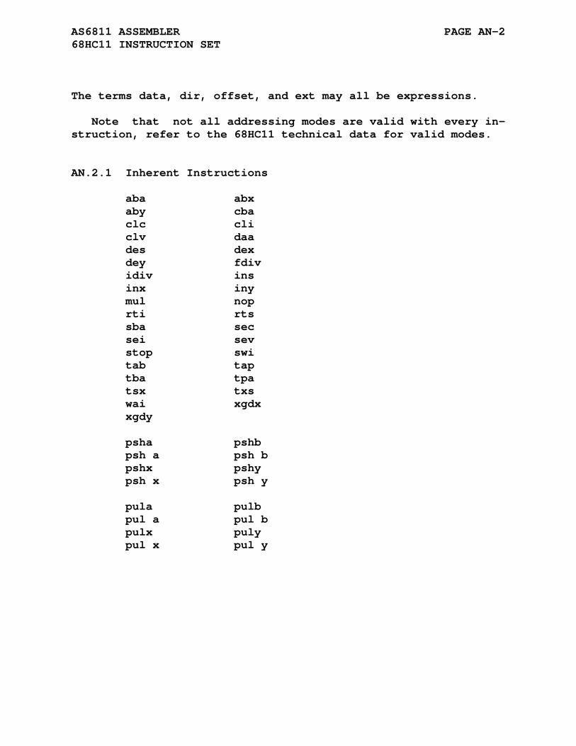
AS6811 ASSEMBLER PAGE AN-2 68HC11 INSTRUCTION SET
The terms data, dir, offset, and ext may all be expressions.
Note that not all addressing modes are valid with every in- struction, refer to the 68HC11 technical data for valid modes.
AN.2.1 Inherent Instructions
aba abx aby cba clc cli clv daa des dex dey fdiv idiv ins inx iny mul nop rti rts sba sec sei sev stop swi tab tap tba tpa tsx txs wai xgdx xgdy psha pshb psh a psh b pshx pshy psh x psh y pula pulb pul a pul b pulx puly pul x pul y
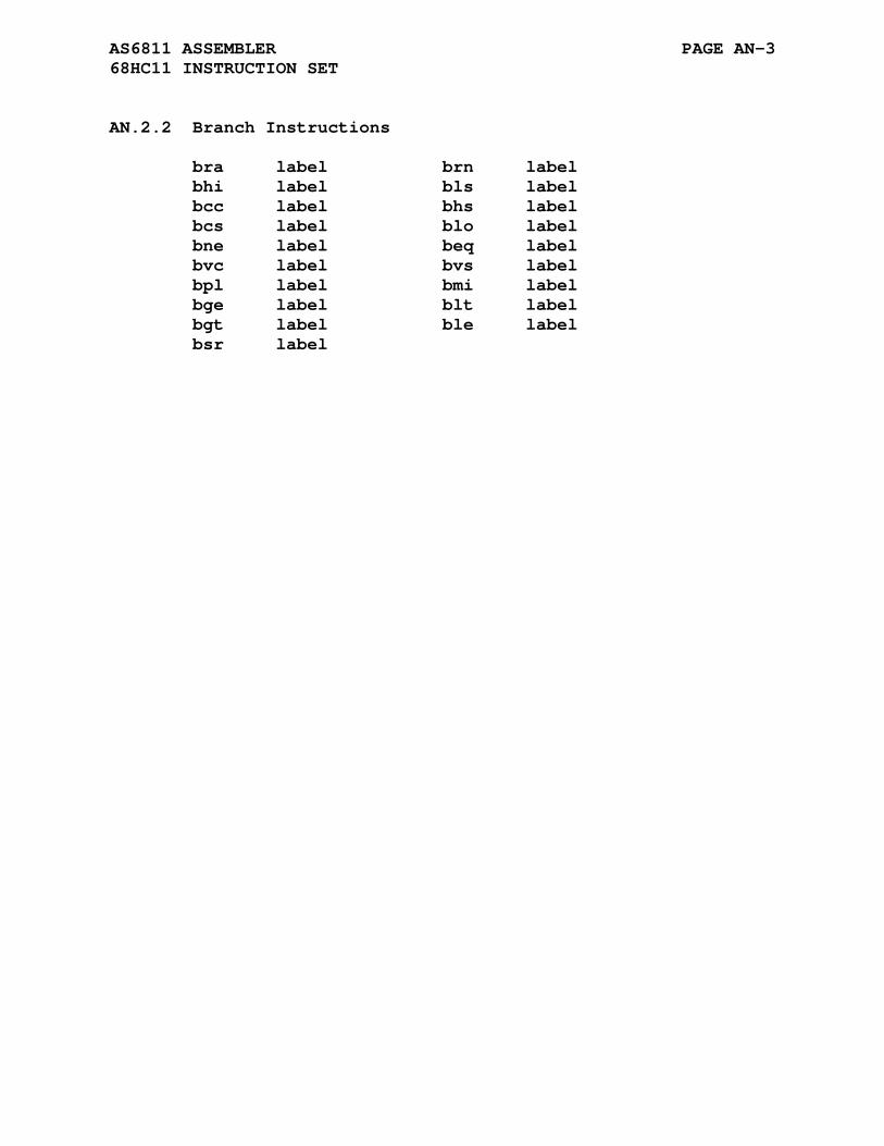
AS6811 ASSEMBLER PAGE AN-3 68HC11 INSTRUCTION SET
AN.2.2 Branch Instructions
bra label brn label bhi label bls label bcc label bhs label bcs label blo label bne label beq label bvc label bvs label bpl label bmi label bge label blt label bgt label ble label bsr label
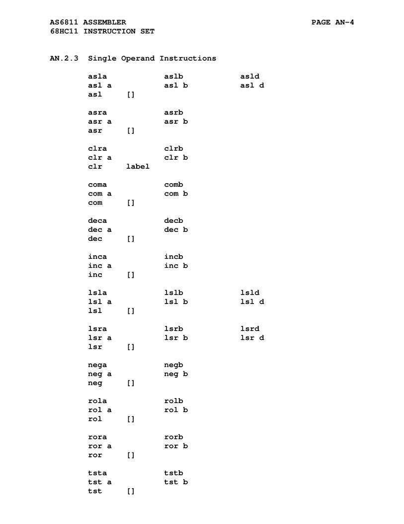
AS6811 ASSEMBLER PAGE AN-4 68HC11 INSTRUCTION SET
AN.2.3 Single Operand Instructions
asla aslb asld asl a asl b asl d asl [] asra asrb asr a asr b asr [] clra clrb clr a clr b clr label coma comb com a com b com [] deca decb dec a dec b dec [] inca incb inc a inc b inc [] lsla lslb lsld lsl a lsl b lsl d lsl [] lsra lsrb lsrd lsr a lsr b lsr d lsr [] nega negb neg a neg b neg [] rola rolb rol a rol b rol [] rora rorb ror a ror b ror [] tsta tstb tst a tst b tst []
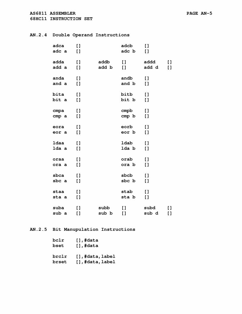
AS6811 ASSEMBLER PAGE AN-5 68HC11 INSTRUCTION SET
AN.2.4 Double Operand Instructions
adca [] adcb [] adc a [] adc b [] adda [] addb [] addd [] add a [] add b [] add d [] anda [] andb [] and a [] and b [] bita [] bitb [] bit a [] bit b [] cmpa [] cmpb [] cmp a [] cmp b [] eora [] eorb [] eor a [] eor b [] ldaa [] ldab [] lda a [] lda b [] oraa [] orab [] ora a [] ora b [] sbca [] sbcb [] sbc a [] sbc b [] staa [] stab [] sta a [] sta b [] suba [] subb [] subd [] sub a [] sub b [] sub d []
AN.2.5 Bit Manupulation Instructions
bclr [],#data bset [],#data brclr [],#data,label brset [],#data,label
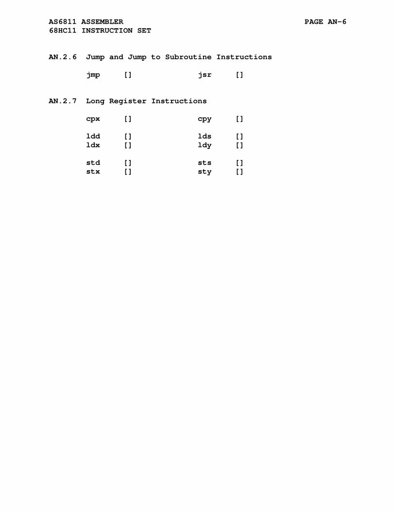
AS6811 ASSEMBLER PAGE AN-6 68HC11 INSTRUCTION SET
AN.2.6 Jump and Jump to Subroutine Instructions
jmp [] jsr []
AN.2.7 Long Register Instructions
cpx [] cpy [] ldd [] lds [] ldx [] ldy [] std [] sts [] stx [] sty []
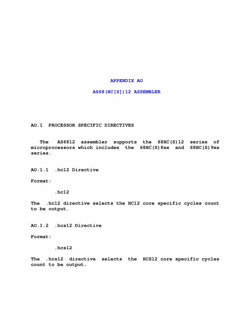
APPENDIX AO
AS68(HC[S])12 ASSEMBLER
AO.1 PROCESSOR SPECIFIC DIRECTIVES
The AS6812 assembler supports the 68HC(S)12 series of microprocessors which includes the 68HC(S)8xx and 68HC(S)9xx series.
AO.1.1 .hc12 Directive
Format:
.hc12
The .hc12 directive selects the HC12 core specific cycles count to be output.
AO.1.2 .hcs12 Directive
Format:
.hcs12
The .hcs12 directive selects the HCS12 core specific cycles count to be output.
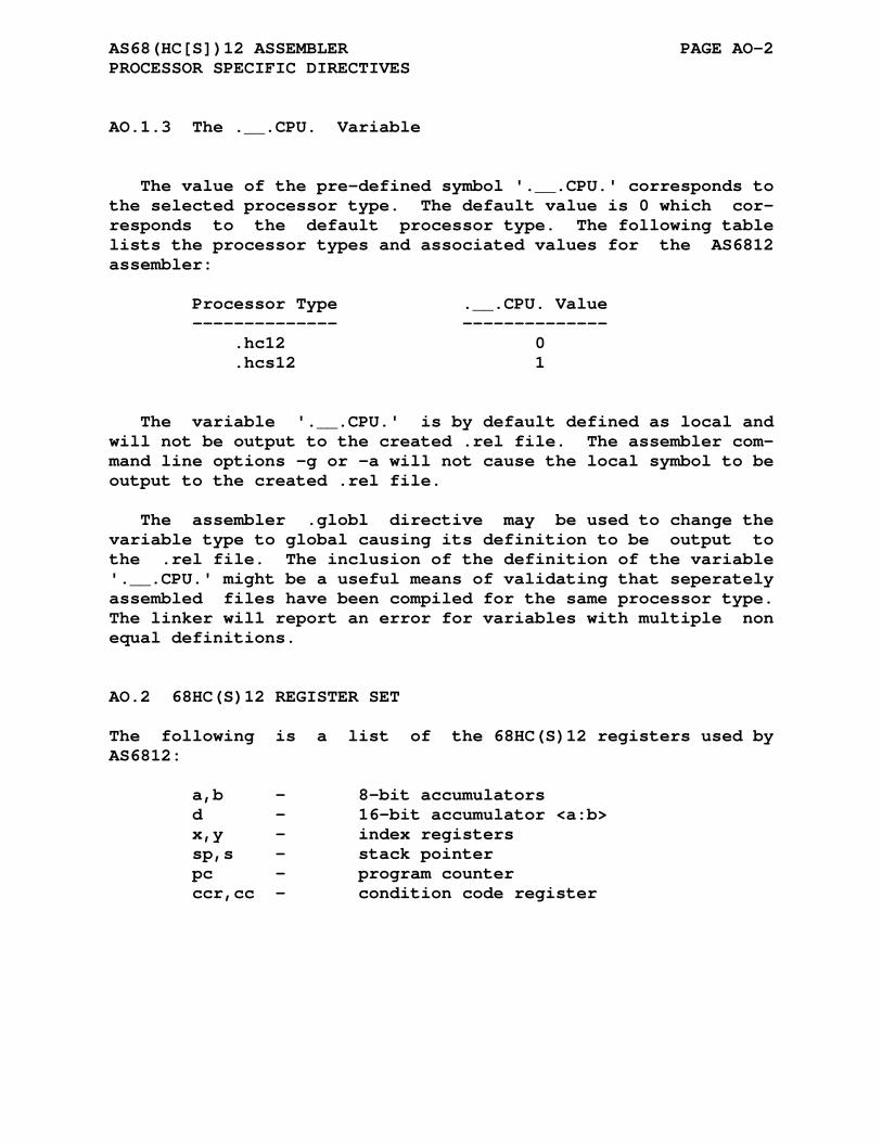
AS68(HC[S])12 ASSEMBLER PAGE AO-2 PROCESSOR SPECIFIC DIRECTIVES
AO.1.3 The .__.CPU. Variable
The value of the pre-defined symbol '.__.CPU.' corresponds to the selected processor type. The default value is 0 which cor- responds to the default processor type. The following table lists the processor types and associated values for the AS6812 assembler:
Processor Type .__.CPU. Value -------------- -------------- .hc12 0 .hcs12 1
The variable '.__.CPU.' is by default defined as local and will not be output to the created .rel file. The assembler com- mand line options -g or -a will not cause the local symbol to be output to the created .rel file.
The assembler .globl directive may be used to change the variable type to global causing its definition to be output to the .rel file. The inclusion of the definition of the variable '.__.CPU.' might be a useful means of validating that seperately assembled files have been compiled for the same processor type. The linker will report an error for variables with multiple non equal definitions.
AO.2 68HC(S)12 REGISTER SET
The following is a list of the 68HC(S)12 registers used by AS6812:
a,b - 8-bit accumulators d - 16-bit accumulator <a:b> x,y - index registers sp,s - stack pointer pc - program counter ccr,cc - condition code register
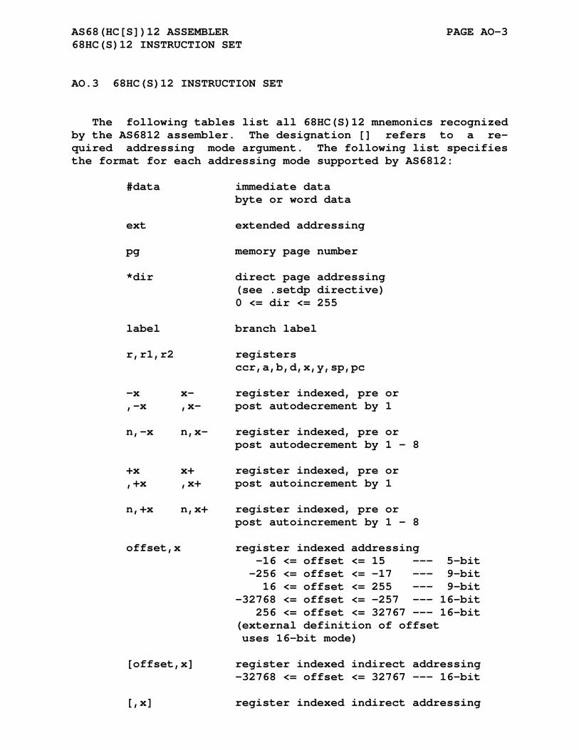
AS68(HC[S])12 ASSEMBLER PAGE AO-3 68HC(S)12 INSTRUCTION SET
AO.3 68HC(S)12 INSTRUCTION SET
The following tables list all 68HC(S)12 mnemonics recognized by the AS6812 assembler. The designation [] refers to a re- quired addressing mode argument. The following list specifies the format for each addressing mode supported by AS6812:
#data immediate data byte or word data ext extended addressing pg memory page number *dir direct page addressing (see .setdp directive) 0 <= dir <= 255 label branch label r,r1,r2 registers ccr,a,b,d,x,y,sp,pc -x x- register indexed, pre or ,-x ,x- post autodecrement by 1 n,-x n,x- register indexed, pre or post autodecrement by 1 - 8 +x x+ register indexed, pre or ,+x ,x+ post autoincrement by 1 n,+x n,x+ register indexed, pre or post autoincrement by 1 - 8 offset,x register indexed addressing -16 <= offset <= 15 --- 5-bit -256 <= offset <= -17 --- 9-bit 16 <= offset <= 255 --- 9-bit -32768 <= offset <= -257 --- 16-bit 256 <= offset <= 32767 --- 16-bit (external definition of offset uses 16-bit mode) [offset,x] register indexed indirect addressing -32768 <= offset <= 32767 --- 16-bit [,x] register indexed indirect addressing
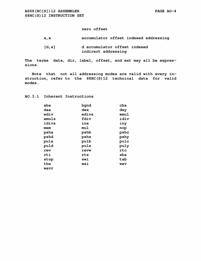
AS68(HC[S])12 ASSEMBLER PAGE AO-4 68HC(S)12 INSTRUCTION SET
zero offset a,x accumulator offset indexed addressing [d,x] d accumulator offset indexed indirect addressing
The terms data, dir, label, offset, and ext may all be expres- sions.
Note that not all addressing modes are valid with every in- struction, refer to the 68HC(S)12 technical data for valid modes.
AO.3.1 Inherent Instructions
aba bgnd cba daa dex dey ediv edivs emul emuls fdiv idiv idivs inx iny mem mul nop psha pshb pshc pshd pshx pshy pula pulb pulc puld pulx puly rev revw rtc rti rts sba stop swi tab tba wai wav wavr
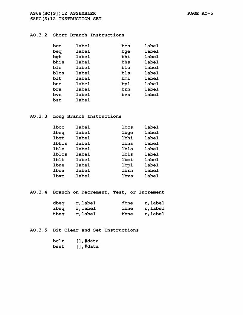
AS68(HC[S])12 ASSEMBLER PAGE AO-5 68HC(S)12 INSTRUCTION SET
AO.3.2 Short Branch Instructions
bcc label bcs label beq label bge label bgt label bhi label bhis label bhs label ble label blo label blos label bls label blt label bmi label bne label bpl label bra label brn label bvc label bvs label bsr label
AO.3.3 Long Branch Instructions
lbcc label lbcs label lbeq label lbge label lbgt label lbhi label lbhis label lbhs label lble label lblo label lblos label lbls label lblt label lbmi label lbne label lbpl label lbra label lbrn label lbvc label lbvs label
AO.3.4 Branch on Decrement, Test, or Increment
dbeq r,label dbne r,label ibeq r,label ibne r,label tbeq r,label tbne r,label
AO.3.5 Bit Clear and Set Instructions
bclr [],#data bset [],#data
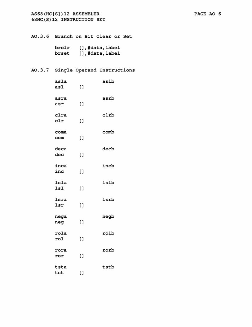
AS68(HC[S])12 ASSEMBLER PAGE AO-6 68HC(S)12 INSTRUCTION SET
AO.3.6 Branch on Bit Clear or Set
brclr [],#data,label brset [],#data,label
AO.3.7 Single Operand Instructions
asla aslb asl [] asra asrb asr [] clra clrb clr [] coma comb com [] deca decb dec [] inca incb inc [] lsla lslb lsl [] lsra lsrb lsr [] nega negb neg [] rola rolb rol [] rora rorb ror [] tsta tstb tst []
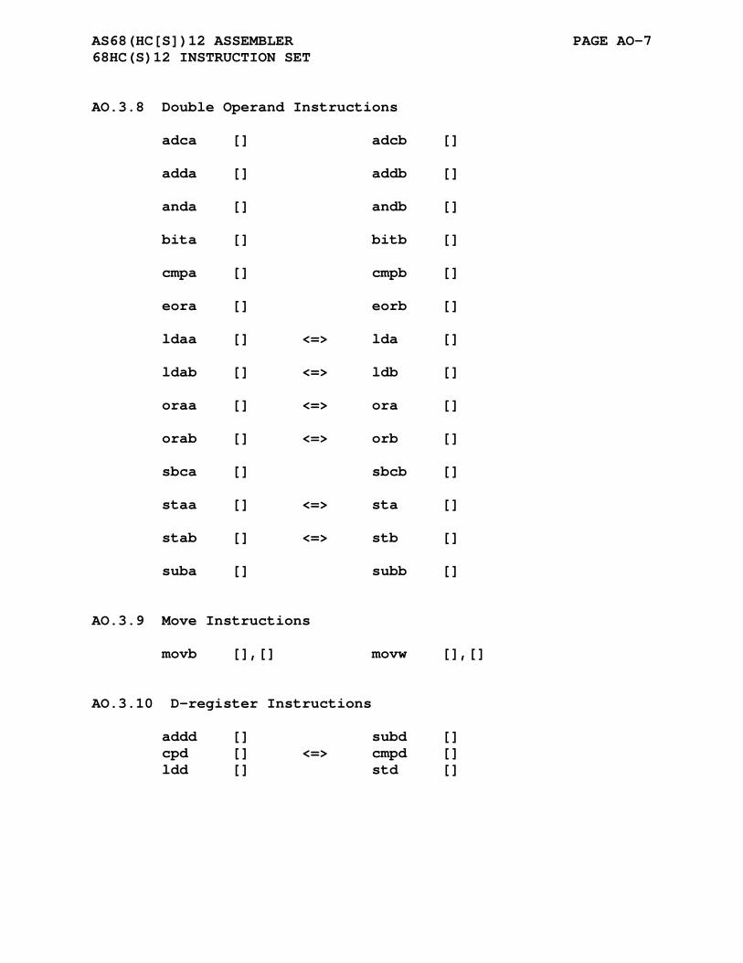
AS68(HC[S])12 ASSEMBLER PAGE AO-7 68HC(S)12 INSTRUCTION SET
AO.3.8 Double Operand Instructions
adca [] adcb [] adda [] addb [] anda [] andb [] bita [] bitb [] cmpa [] cmpb [] eora [] eorb [] ldaa [] <=> lda [] ldab [] <=> ldb [] oraa [] <=> ora [] orab [] <=> orb [] sbca [] sbcb [] staa [] <=> sta [] stab [] <=> stb [] suba [] subb []
AO.3.9 Move Instructions
movb [],[] movw [],[]
AO.3.10 D-register Instructions
addd [] subd [] cpd [] <=> cmpd [] ldd [] std []

AS68(HC[S])12 ASSEMBLER PAGE AO-8 68HC(S)12 INSTRUCTION SET
AO.3.11 Index/Stack Register Instructions
cps [] <=> cmps [] cpx [] <=> cmpx [] cpy [] <=> cmpy [] lds [] ldx [] ldy [] leas [] leax [] leay [] sts [] stx [] sty []
AO.3.12 Jump and Jump/Call to Subroutine Instructions
call [],pg jmp [] jsr []
AO.3.13 Other Special Instructions
emacs [] emaxd [] emaxm [] emind [] eminm [] etbl [] maxa [] maxm [] mina [] minm [] tbl [] trap #data
AO.3.14 Register - Register Instructions
exg r1,r2 sex r1,r2 tfr r1,r2
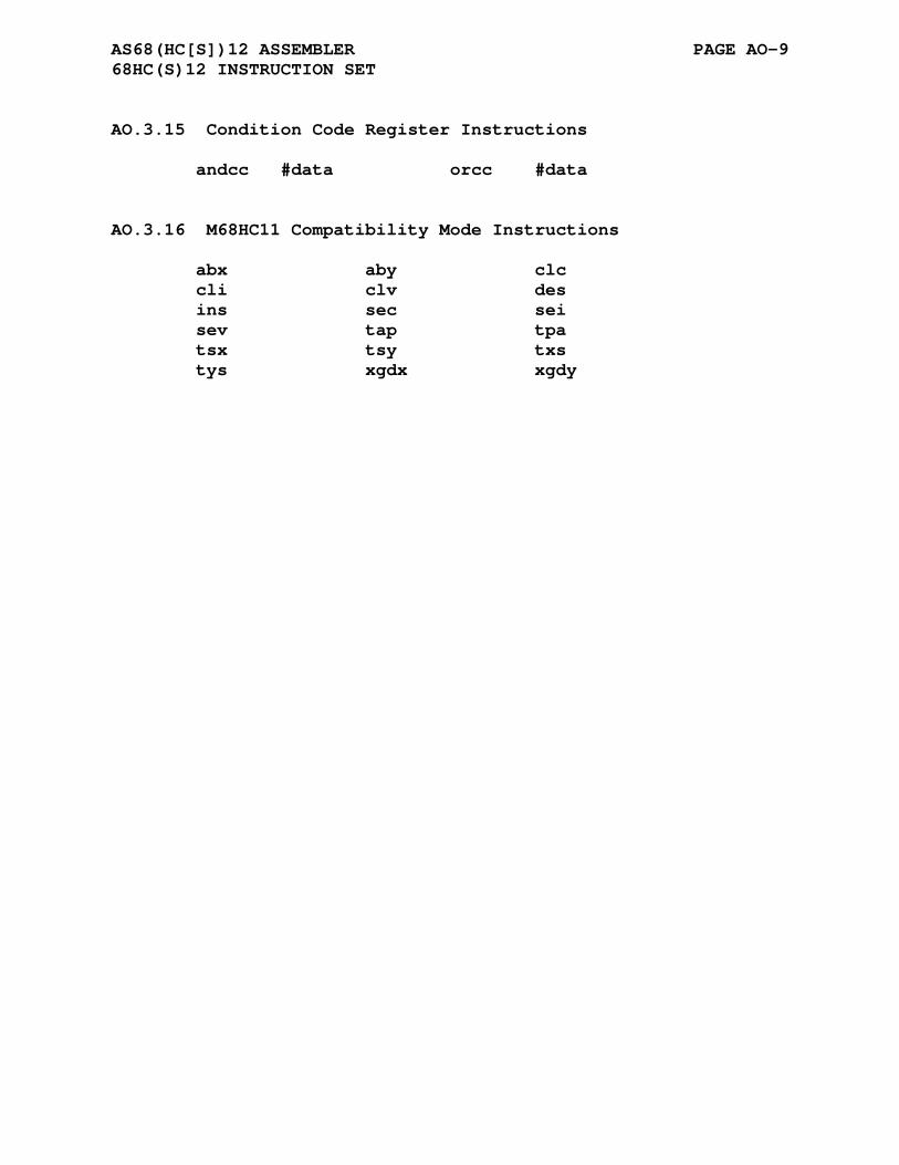
AS68(HC[S])12 ASSEMBLER PAGE AO-9 68HC(S)12 INSTRUCTION SET
AO.3.15 Condition Code Register Instructions
andcc #data orcc #data
AO.3.16 M68HC11 Compatibility Mode Instructions
abx aby clc cli clv des ins sec sei sev tap tpa tsx tsy txs tys xgdx xgdy

APPENDIX AP
AS6816 ASSEMBLER
AP.1 68HC16 REGISTER SET
The following is a list of the 68HC16 registers used by AS6816:
a,b - 8-bit accumulators d - 16-bit accumulator <a:b> e - 16-bit accumulator x,y,z - index registers k - address extension register s - stack pointer ccr - condition code
AP.2 68HC16 INSTRUCTION SET
The following tables list all 68HC16 mnemonics recognized by the AS6816 assembler. The designation [] refers to a required addressing mode argument. The following list specifies the format for each addressing mode supported by AS6816:
#data immediate data byte or word data #xo,#yo local immediate data (mac / rmac) label branch label r register ccr,a,b,d,e,x,y,z,s ,x zero offset register indexed addressing ,x8
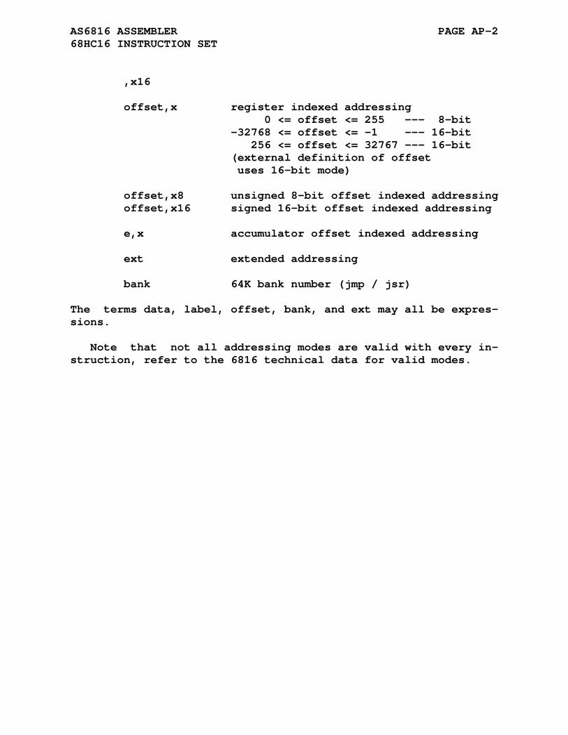
AS6816 ASSEMBLER PAGE AP-2 68HC16 INSTRUCTION SET
,x16 offset,x register indexed addressing 0 <= offset <= 255 --- 8-bit -32768 <= offset <= -1 --- 16-bit 256 <= offset <= 32767 --- 16-bit (external definition of offset uses 16-bit mode) offset,x8 unsigned 8-bit offset indexed addressing offset,x16 signed 16-bit offset indexed addressing e,x accumulator offset indexed addressing ext extended addressing bank 64K bank number (jmp / jsr)
The terms data, label, offset, bank, and ext may all be expres- sions.
Note that not all addressing modes are valid with every in- struction, refer to the 6816 technical data for valid modes.
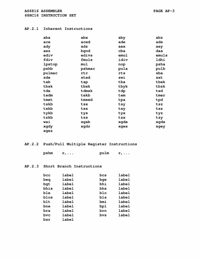
AS6816 ASSEMBLER PAGE AP-3 68HC16 INSTRUCTION SET
AP.2.1 Inherent Instructions
aba abx aby abz ace aced ade adx ady adz aex aey aez bgnd cba daa ediv edivs emul emuls fdiv fmuls idiv ldhi lpstop mul nop psha pshb pshmac pula pulb pulmac rtr rts sba sde sted swi sxt tab tap tba tbek tbsk tbxk tbyk tbzk tde tdmsk tdp ted tedm tekb tem tmer tmet tmxed tpa tpd tskb tsx tsy tsz txkb txs txy txz tykb tys tyx tyz tzkb tzs tzx tzy wai xgab xgde xgdx xgdy xgdz xgex xgey xgez
AP.2.2 Push/Pull Multiple Register Instructions
pshm r,... pulm r,...
AP.2.3 Short Branch Instructions
bcc label bcs label beq label bge label bgt label bhi label bhis label bhs label ble label blo label blos label bls label blt label bmi label bne label bpl label bra label brn label bvc label bvs label bsr label
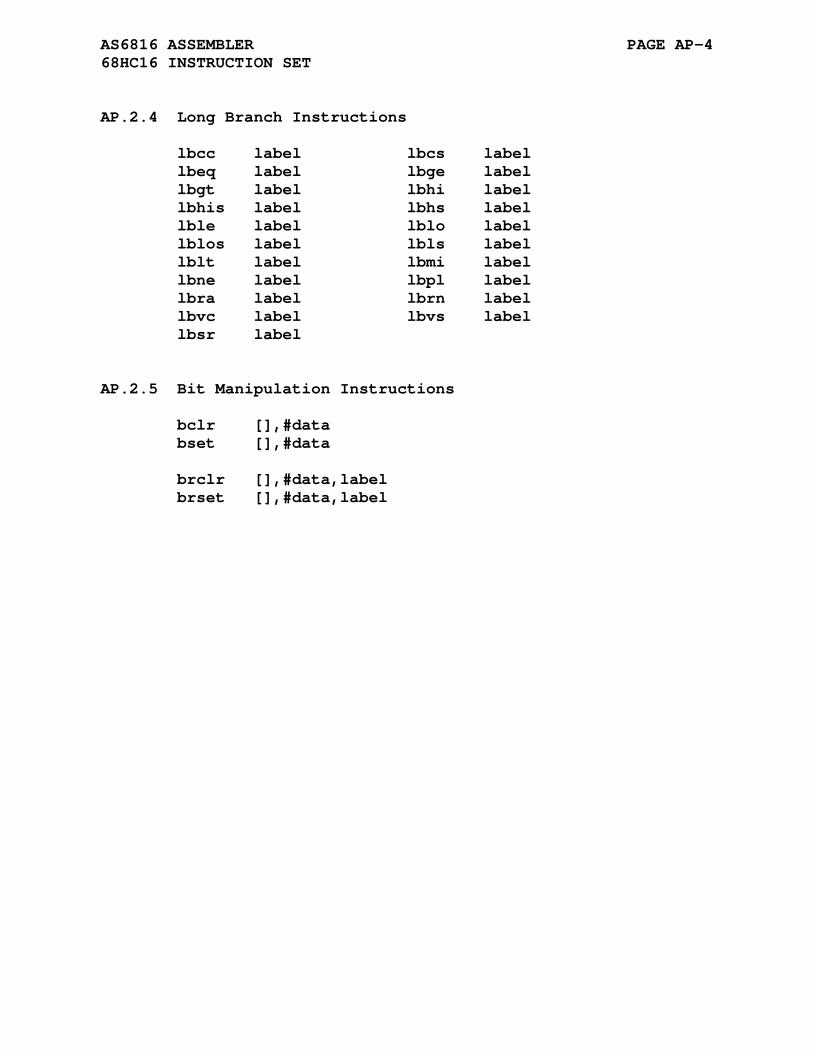
AS6816 ASSEMBLER PAGE AP-4 68HC16 INSTRUCTION SET
AP.2.4 Long Branch Instructions
lbcc label lbcs label lbeq label lbge label lbgt label lbhi label lbhis label lbhs label lble label lblo label lblos label lbls label lblt label lbmi label lbne label lbpl label lbra label lbrn label lbvc label lbvs label lbsr label
AP.2.5 Bit Manipulation Instructions
bclr [],#data bset [],#data brclr [],#data,label brset [],#data,label
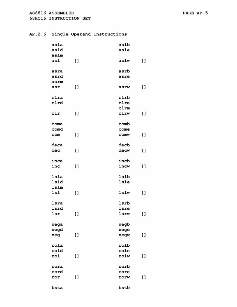
AS6816 ASSEMBLER PAGE AP-5 68HC16 INSTRUCTION SET
AP.2.6 Single Operand Instructions
asla aslb asld asle aslm asl [] aslw [] asra asrb asrd asre asrm asr [] asrw [] clra clrb clrd clre clrm clr [] clrw [] coma comb comd come com [] comw [] deca decb dec [] decw [] inca incb inc [] incw [] lsla lslb lsld lsle lslm lsl [] lslw [] lsra lsrb lsrd lsre lsr [] lsrw [] nega negb negd nege neg [] negw [] rola rolb rold role rol [] rolw [] rora rorb rord rore ror [] rorw [] tsta tstb
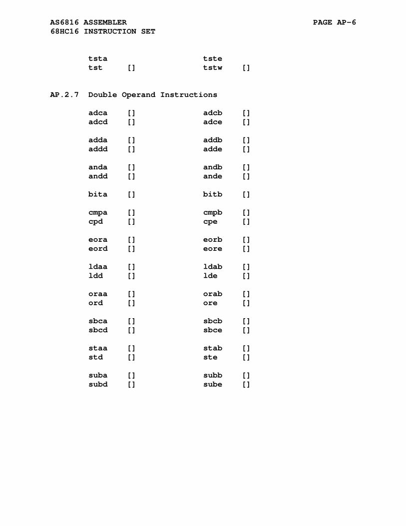
AS6816 ASSEMBLER PAGE AP-6 68HC16 INSTRUCTION SET
tsta tste tst [] tstw []
AP.2.7 Double Operand Instructions
adca [] adcb [] adcd [] adce [] adda [] addb [] addd [] adde [] anda [] andb [] andd [] ande [] bita [] bitb [] cmpa [] cmpb [] cpd [] cpe [] eora [] eorb [] eord [] eore [] ldaa [] ldab [] ldd [] lde [] oraa [] orab [] ord [] ore [] sbca [] sbcb [] sbcd [] sbce [] staa [] stab [] std [] ste [] suba [] subb [] subd [] sube []
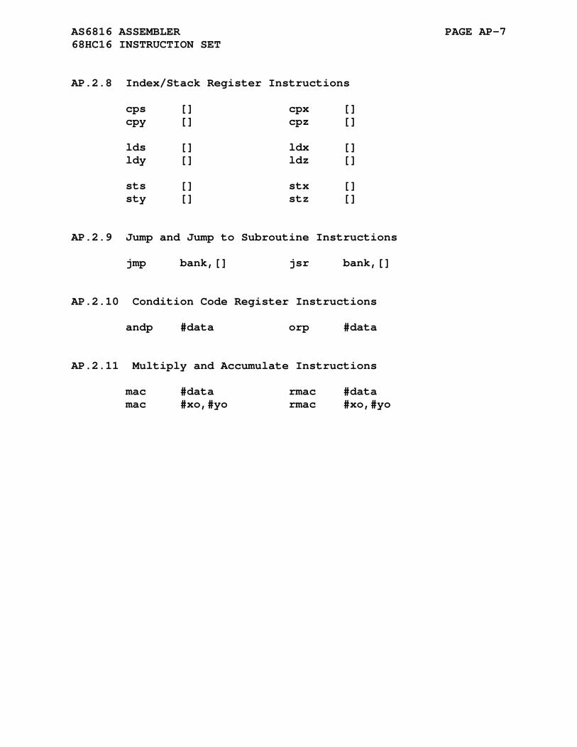
AS6816 ASSEMBLER PAGE AP-7 68HC16 INSTRUCTION SET
AP.2.8 Index/Stack Register Instructions
cps [] cpx [] cpy [] cpz [] lds [] ldx [] ldy [] ldz [] sts [] stx [] sty [] stz []
AP.2.9 Jump and Jump to Subroutine Instructions
jmp bank,[] jsr bank,[]
AP.2.10 Condition Code Register Instructions
andp #data orp #data
AP.2.11 Multiply and Accumulate Instructions
mac #data rmac #data mac #xo,#yo rmac #xo,#yo

APPENDIX AQ
AS740 ASSEMBLER
AQ.1 ACKNOWLEDGMENT
Thanks to Uwe Steller for his contribution of the AS740 cross assembler.
Uwe Stellar Uwe dot Steller at t-online dot de
The instruction syntax of this cross assembler uses the square brackets [] to denote addressing indirection.
AQ.2 740 REGISTER SET
The following is a list of the 740 registers used by AS740:
a - 8-bit accumulator x,y - index registers
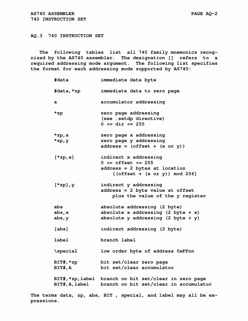
AS740 ASSEMBLER PAGE AQ-2 740 INSTRUCTION SET
AQ.3 740 INSTRUCTION SET
The following tables list all 740 family mnemonics recog- nized by the AS740 assembler. The designation [] refers to a required addressing mode argument. The following list specifies the format for each addressing mode supported by AS740:
#data immediate data byte #data,*zp immediate data to zero page a accumulator addressing *zp zero page addressing (see .setdp directive) 0 <= dir <= 255 *zp,x zero page x addressing *zp,y zero page y addressing address = (offset + (x or y)) [*zp,x] indirect x addressing 0 <= offset <= 255 address = 2 bytes at location [(offset + (x or y)) mod 256] [*zp],y indirect y addressing address = 2 byte value at offset plus the value of the y register abs absolute addressing (2 byte) abs,x absolute x addressing (2 byte + x) abs,y absolute y addressing (2 byte + y) [abs] indirect addressing (2 byte) label branch label \special low order byte of address 0xFFnn BIT#,*zp bit set/clear zero page BIT#,A bit set/clear accumulator BIT#,*zp,label branch on bit set/clear in zero page BIT#,A,label branch on bit set/clear in accumulator
The terms data, zp, abs, BIT , special, and label may all be ex- pressions.
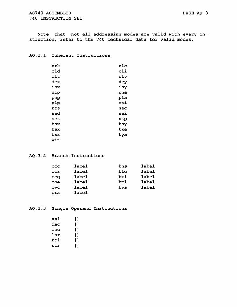
AS740 ASSEMBLER PAGE AQ-3 740 INSTRUCTION SET
Note that not all addressing modes are valid with every in- struction, refer to the 740 technical data for valid modes.
AQ.3.1 Inherent Instructions
brk clc cld cli clt clv dex dey inx iny nop pha php pla plp rti rts sec sed sei set stp tax tay tsx txa txs tya wit
AQ.3.2 Branch Instructions
bcc label bhs label bcs label blo label beq label bmi label bne label bpl label bvc label bvs label bra label
AQ.3.3 Single Operand Instructions
asl [] dec [] inc [] lsr [] rol [] ror []
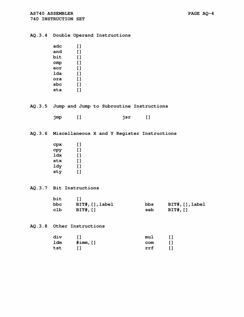
AS740 ASSEMBLER PAGE AQ-4 740 INSTRUCTION SET
AQ.3.4 Double Operand Instructions
adc [] and [] bit [] cmp [] eor [] lda [] ora [] sbc [] sta []
AQ.3.5 Jump and Jump to Subroutine Instructions
jmp [] jsr []
AQ.3.6 Miscellaneous X and Y Register Instructions
cpx [] cpy [] ldx [] stx [] ldy [] sty []
AQ.3.7 Bit Instructions
bit [] bbc BIT#,[],label bbs BIT#,[],label clb BIT#,[] seb BIT#,[]
AQ.3.8 Other Instructions
div [] mul [] ldm #imm,[] com [] tst [] rrf []
APPENDIX AR
AS78K0 ASSEMBLER
AR.1 PROCESSOR SPECIFIC DIRECTIVES
AR.1.1 .setdp Directive
Format:
.setdp [base [,area]]
The set direct page directive has a common format in all the as- semblers supporting a paged mode. The .setdp directive is used to inform the AS78K0 assembler of the current SFR page region and the offset address within the selected area. The normal in- vocation methods are:
.area SFR (PAG) .setdp or .setdp 0xFF00,SFR
The directives specify that the direct page is in area SFR and its offset address is 0xFF00 (the only valid value for all r78k0 microprocessor variations). Be sure to place the SFR area at address 0xFF00 during linking. When the base address and area are not specified, then 0xFF00 and the current area are the defaults. If a .setdp directive is not issued the assembler defaults the direct page to the area "CODE" at offset 0xFF00.

AS78K0 ASSEMBLER PAGE AR-2 PROCESSOR SPECIFIC DIRECTIVES
The assembler verifies that any local variable used in an SFR variable reference is located in this area. Local variable and constant value direct access addresses are checked to be within the address range from 0xFF00 to 0xFFFF.
External SFR references are assumed by the assembler to be in the correct area and have valid offsets. The linker will check all SFR page relocations to verify that they are within the cor- rect area.
AR.1.2 .xerr Directive
Format:
.xerr [n]
The expanded error directive outputs alternate error messages for the <a> error at the commmand line and in the listing files created by the assembler. The modes are:
.xerr [0] Restores the default <a> error reporting. .xerr 1 Replaces the <a> error with the <x> error which lists the source line containing the error on the stdout device. .xerr 2 Replaces the <a> error with the <x> error which lists the source line containing the error on the stdout device and also outputs an additional <x> error describing the detected error. .xerr 3 Replaces the <a> error with the <x> error which lists the source line containing the error on the stdout device and also outputs an additional <x> error describing the detected error. The additional <x> error describing the detected error is inserted into the optional listing file.
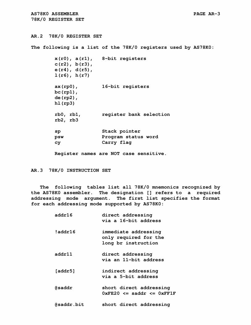
AS78K0 ASSEMBLER PAGE AR-3 78K/0 REGISTER SET
AR.2 78K/0 REGISTER SET
The following is a list of the 78K/0 registers used by AS78K0:
x(r0), a(r1), 8-bit registers c(r2), b(r3), e(r4), d(r5), l(r6), h(r7) ax(rp0), 16-bit registers bc(rp1), de(rp2), hl(rp3) rb0, rb1, register bank selection rb2, rb3 sp Stack pointer psw Program status word cy Carry flag Register names are NOT case sensitive.
AR.3 78K/0 INSTRUCTION SET
The following tables list all 78K/0 mnemonics recognized by the AS78K0 assembler. The designation [] refers to a required addressing mode argument. The first list specifies the format for each addressing mode supported by AS78K0:
addr16 direct addressing via a 16-bit address !addr16 immediate addressing only required for the long br instruction addr11 direct addressing via an 11-bit address [addr5] indirect addressing via a 5-bit address @saddr short direct addressing 0xFE20 <= saddr <= 0xFF1F @saddr.bit short direct addressing

AS78K0 ASSEMBLER PAGE AR-4 78K/0 INSTRUCTION SET
@saddr,bit with bit addressing (0-7) 0xFE20 <= saddr <= 0xFF1F *sfr special function registers 0xFF00 <= sfr <= 0xFFCF or 0xFFE0 <= sfr <= 0xFFFF *sfr.bit special function registers *sfr,bit wiht bit addressing (0-7) 0xFF00 <= sfr <= 0xFFCF or 0xFFE0 <= sfr <= 0xFFFF label branch label (pc relative addressing) #byte immediate data (8 bit) #word immediate data (16 bit) rn registers (8 bit) x, a, c, b, e, d, l, h r0-r7 rpn registers (16 bit) ax, bc, de, hl rp0-rp3 rbn register bank rb0-rb3 sp stack pointer psw program status register cy carry flag [DE], [HL] register indirect addressing [HL+byte] based register indirect addressing [HL,byte] [HL+B] [HL,B] [HL+C] [HL,C] [HL].bit register indirect addressing with bit addressing

AS78K0 ASSEMBLER PAGE AR-5 78K/0 INSTRUCTION SET
The terms addr16, addr11, addr5, saddr, sfr, bit, label, byte, and word may all be expressions.
Absolute addresses (CONSTANTS) will be checked as being in the 'saddr' range first and then as being in the 'sfr' range if no explicit @ or * is specified.
The bit addressing modes *sfr.bit and @saddr.bit use the '.' as a seperator from the address and the bit value. The bit value can be a numeric constant, a named constant, an expres- sion, or a combination of these. Because the '.' is also a le- gal character in a name or label the assembler may not be able to resolve the address and bit value. The optional method of using a ',' to seperate the address and bit value may be used in this case.
If the 'sfr' or 'saddr' address is external then the user is responsible to ensure the addresses are in the proper ranges. Paging ERRORS for 'sfr' may be reported by the linker.
Note that not all addressing modes are valid with every in- struction, refer to the 78K/0 technical data for valid modes.
AR.3.1 Inherent Instructions
nop halt stop ret retb reti di ei brk adjba adjbs
AR.3.2 Branch Instructions
bc label bnc label bz label bnz label br [] dbnz [],addr16 bt [],addr16 bf [],addr16 btclr [],addr16
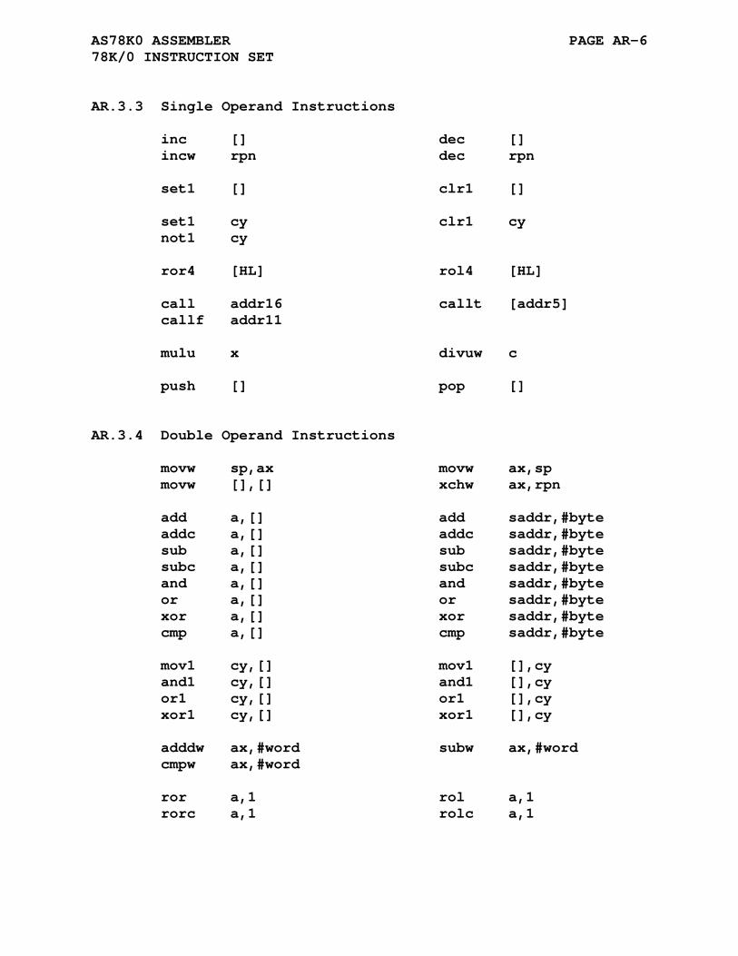
AS78K0 ASSEMBLER PAGE AR-6 78K/0 INSTRUCTION SET
AR.3.3 Single Operand Instructions
inc [] dec [] incw rpn dec rpn set1 [] clr1 [] set1 cy clr1 cy not1 cy ror4 [HL] rol4 [HL] call addr16 callt [addr5] callf addr11 mulu x divuw c push [] pop []
AR.3.4 Double Operand Instructions
movw sp,ax movw ax,sp movw [],[] xchw ax,rpn add a,[] add saddr,#byte addc a,[] addc saddr,#byte sub a,[] sub saddr,#byte subc a,[] subc saddr,#byte and a,[] and saddr,#byte or a,[] or saddr,#byte xor a,[] xor saddr,#byte cmp a,[] cmp saddr,#byte mov1 cy,[] mov1 [],cy and1 cy,[] and1 [],cy or1 cy,[] or1 [],cy xor1 cy,[] xor1 [],cy adddw ax,#word subw ax,#word cmpw ax,#word ror a,1 rol a,1 rorc a,1 rolc a,1

APPENDIX AS
AS78K0S ASSEMBLER
AS.1 78K/0S REGISTER SET
The following is a list of the 78K/0S registers used by AS78K0S:
x(r0), a(r1), 8-bit registers c(r2), b(r3), e(r4), d(r5), l(r6), h(r7) ax(rp0), 16-bit registers bc(rp1), de(rp2), hl(rp3) sp Stack pointer psw Program status word cy Carry flag Register names are NOT case sensitive.
AS.2 78K/0S INSTRUCTION SET
The following tables list all 78K/0S mnemonics recognized by the AS78K0S assembler. The designation [] refers to a required addressing mode argument. The first list specifies the format for each addressing mode supported by AS78K0S:
addr16 direct addressing via 16-bit address !addr16 immediate addressing
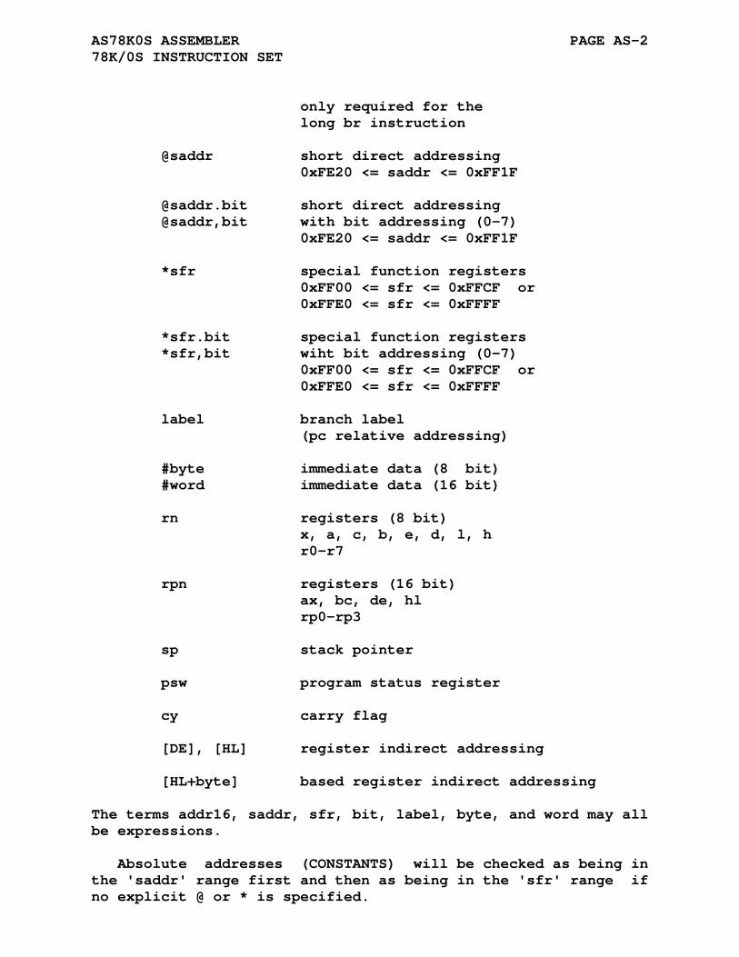
AS78K0S ASSEMBLER PAGE AS-2 78K/0S INSTRUCTION SET
only required for the long br instruction @saddr short direct addressing 0xFE20 <= saddr <= 0xFF1F @saddr.bit short direct addressing @saddr,bit with bit addressing (0-7) 0xFE20 <= saddr <= 0xFF1F *sfr special function registers 0xFF00 <= sfr <= 0xFFCF or 0xFFE0 <= sfr <= 0xFFFF *sfr.bit special function registers *sfr,bit wiht bit addressing (0-7) 0xFF00 <= sfr <= 0xFFCF or 0xFFE0 <= sfr <= 0xFFFF label branch label (pc relative addressing) #byte immediate data (8 bit) #word immediate data (16 bit) rn registers (8 bit) x, a, c, b, e, d, l, h r0-r7 rpn registers (16 bit) ax, bc, de, hl rp0-rp3 sp stack pointer psw program status register cy carry flag [DE], [HL] register indirect addressing [HL+byte] based register indirect addressing
The terms addr16, saddr, sfr, bit, label, byte, and word may all be expressions.
Absolute addresses (CONSTANTS) will be checked as being in the 'saddr' range first and then as being in the 'sfr' range if no explicit @ or * is specified.
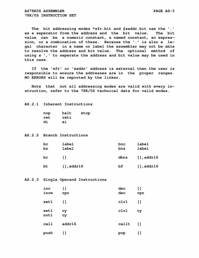
AS78K0S ASSEMBLER PAGE AS-3 78K/0S INSTRUCTION SET
The bit addressing modes *sfr.bit and @saddr.bit use the '.' as a seperator from the address and the bit value. The bit value can be a numeric constant, a named constant, an expres- sion, or a combination of these. Because the '.' is also a le- gal character in a name or label the assembler may not be able to resolve the address and bit value. The optional method of using a ',' to seperate the address and bit value may be used in this case.
If the 'sfr' or 'saddr' address is external then the user is responsible to ensure the addresses are in the proper ranges. NO ERRORS will be reported by the linker.
Note that not all addressing modes are valid with every in- struction, refer to the 78K/0S technical data for valid modes.
AS.2.1 Inherent Instructions
nop halt stop ret reti di ei
AS.2.2 Branch Instructions
bc label bnc label bz label bnz label br [] dbnz [],addr16 bt [],addr16 bf [],addr16
AS.2.3 Single Operand Instructions
inc [] dec [] incw rpn dec rpn set1 [] clr1 [] set1 cy clr1 cy not1 cy call addr16 callt [] push [] pop []
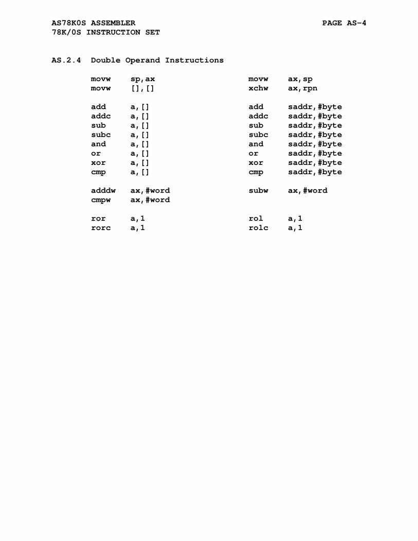
AS78K0S ASSEMBLER PAGE AS-4 78K/0S INSTRUCTION SET
AS.2.4 Double Operand Instructions
movw sp,ax movw ax,sp movw [],[] xchw ax,rpn add a,[] add saddr,#byte addc a,[] addc saddr,#byte sub a,[] sub saddr,#byte subc a,[] subc saddr,#byte and a,[] and saddr,#byte or a,[] or saddr,#byte xor a,[] xor saddr,#byte cmp a,[] cmp saddr,#byte adddw ax,#word subw ax,#word cmpw ax,#word ror a,1 rol a,1 rorc a,1 rolc a,1
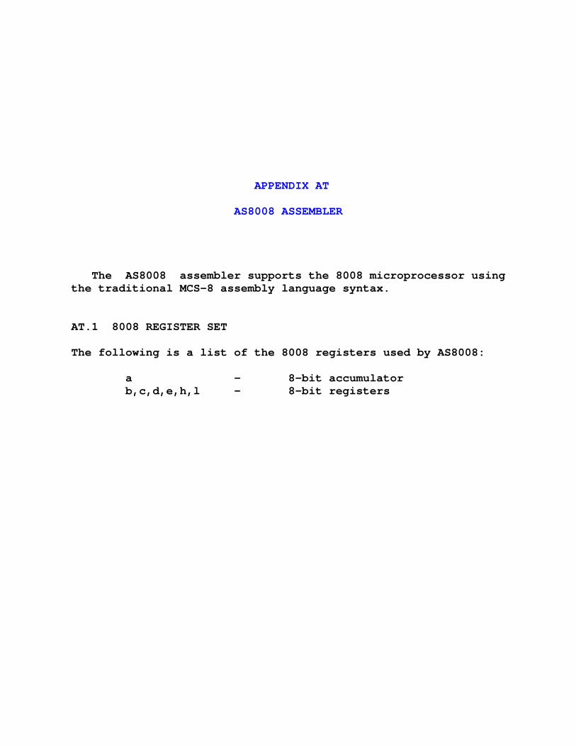
APPENDIX AT
AS8008 ASSEMBLER
The AS8008 assembler supports the 8008 microprocessor using the traditional MCS-8 assembly language syntax.
AT.1 8008 REGISTER SET
The following is a list of the 8008 registers used by AS8008:
a - 8-bit accumulator b,c,d,e,h,l - 8-bit registers
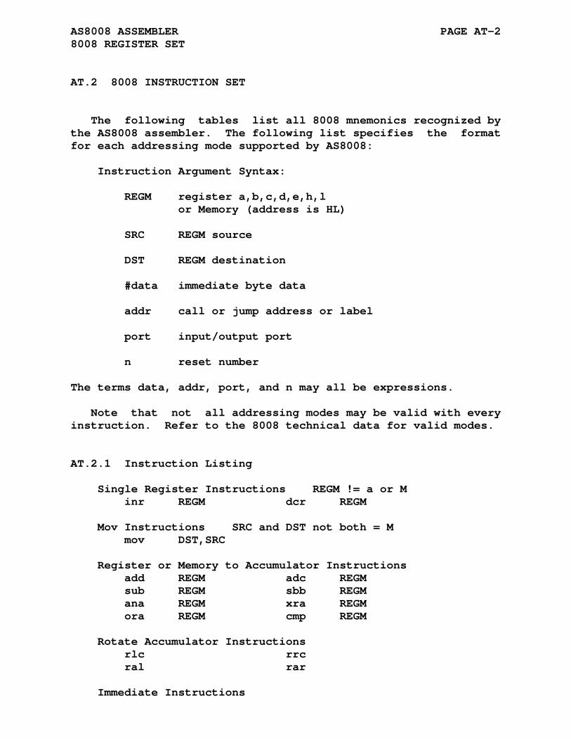
AS8008 ASSEMBLER PAGE AT-2 8008 REGISTER SET
AT.2 8008 INSTRUCTION SET
The following tables list all 8008 mnemonics recognized by the AS8008 assembler. The following list specifies the format for each addressing mode supported by AS8008:
Instruction Argument Syntax: REGM register a,b,c,d,e,h,l or Memory (address is HL) SRC REGM source DST REGM destination #data immediate byte data addr call or jump address or label port input/output port n reset number
The terms data, addr, port, and n may all be expressions.
Note that not all addressing modes may be valid with every instruction. Refer to the 8008 technical data for valid modes.
AT.2.1 Instruction Listing
Single Register Instructions REGM != a or M inr REGM dcr REGM Mov Instructions SRC and DST not both = M mov DST,SRC Register or Memory to Accumulator Instructions add REGM adc REGM sub REGM sbb REGM ana REGM xra REGM ora REGM cmp REGM Rotate Accumulator Instructions rlc rrc ral rar Immediate Instructions

AS8008 ASSEMBLER PAGE AT-3 8008 INSTRUCTION SET
movi REGM,#data adi #data aci #data sui #data sbi #data ani #data xri #data ori #data cpi #data Jump Instructions jmp addr jc addr jnc addr jz addr jnz addr jp addr jm addr jpe addr jpo addr Call Instructions call addr cc addr cnc addr cz addr cnz addr cp addr cm addr cpe addr cpo addr Return Instructions rte rc rnc rz rnz rp rm rpe rpo Reset Instruction rst n 0 <= n <= 7 Input/Output Instructions in port 0 <= port <= 7 out port 8 <= port <= 31 Halt and No-Operation Instruction hlt nop
APPENDIX AU
AS8008S ASSEMBLER
The AS8008S assembler supports the 8008 microprocessor using the early MCS-8 assembly language syntax of a Fortan based as- sembler/simulator (SIM-8) which had minimal lexical analysis. The instruction set contains a mnemonic for every variation of the basic instruction types. As an example the load accumulator operation has a mnemonic for load a with a (laa), load a with b (lab), load a with c (lac), load a with d (lad), load a with e (lae), load a with h (lah), and load a with l (lal).
AU.1 8008 REGISTER SET
The following is a list of the 8008 registers used by AS8008S:
a - 8-bit accumulator b,c,d,e,h,l - 8-bit registers c,z,s,p - status word bits

AS8008S ASSEMBLER PAGE AU-2 8008 REGISTER SET
AU.2 8008 INSTRUCTION SET
The following tables list all 8008 mnemonics recognized by the AS8008S assembler. The following list specifies the format for each addressing mode supported by AS8008S:
Instruction Mnemonic Syntax: r register a,b,c,d,e,h,l c status bits c,z,s,p M memory access I immediate access Instruction Argument Syntax: #data immediate data byte or word data label call or jump label MMM input/output port
The terms data, label, and MMM may all be expressions.
Note that not all addressing modes may be valid with every instruction. Refer to the 8008 technical data for valid modes.
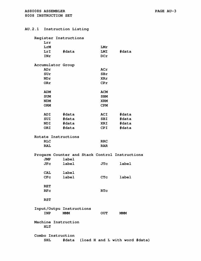
AS8008S ASSEMBLER PAGE AU-3 8008 INSTRUCTION SET
AU.2.1 Instruction Listing
Register Instructions Lrr LrM LMr LrI #data LMI #data INr DCr Accumulator Group ADr ACr SUr SBr NDr XRr ORr CPr ADM ACM SUM SBM NDM XRM ORM CPM ADI #data ACI #data SUI #data SBI #data NDI #data XRI #data ORI #data CPI #data Rotate Instructions RLC RRC RAL RAR Progarm Counter and Stack Control Instructions JMP label JFc label JTc label CAL label CFc label CTc label RET RFc RTc RST Input/Outpu Instructions INP MMM OUT MMM Machine Instruction HLT Combo Instruction SHL #data (load H and L with word #data)

APPENDIX AV
AS8048 ASSEMBLER
AS8048 supports the 8048, 8041, 8022, and 8021 variations of the 8048 microprocessor family.
AV.1 .8048 DIRECTIVE
Format:
.8048
The .8048 directive enables processing of only the 8048 specific mnemonics. 8041/8022/8021 mnemonics encountered will be flagged with an <o> error.
AV.2 .8041 DIRECTIVE
Format:
.8041
The .8041 directive enables processing of the 8041 specific mnemonics. 8041 mnemonics encountered without the .8041 direc- tive will be flagged with an <o> error.

AS8048 ASSEMBLER PAGE AV-2 .8022 DIRECTIVE
AV.3 .8022 DIRECTIVE
Format:
.8022
The .8022 directive enables processing of the 8022 specific mnemonics. 8022 mnemonics encountered without the .8022 direc- tive will be flagged with an <o> error.
AV.4 .8021 DIRECTIVE
Format:
.8021
The .8021 directive enables processing of the 8021 specific mnemonics. 8021 mnemonics encountered without the .8021 direc- tive will be flagged with an <o> error.
AV.5 THE .__.CPU. VARIABLE
The value of the pre-defined symbol '.__.CPU.' corresponds to the selected processor type. The default value is 0 which cor- responds to the default processor type. The following table lists the processor types and associated values for the AS8048 assembler:
Processor Type .__.CPU. Value -------------- -------------- .8048 0 .8041 1 .8022 2 .8021 3
The variable '.__.CPU.' is by default defined as local and will not be output to the created .rel file. The assembler com- mand line options -g or -a will not cause the local symbol to be output to the created .rel file.
The assembler .globl directive may be used to change the variable type to global causing its definition to be output to the .rel file. The inclusion of the definition of the variable '.__.CPU.' might be a useful means of validating that seperately assembled files have been compiled for the same processor type.

AS8048 ASSEMBLER PAGE AV-3 THE .__.CPU. VARIABLE
The linker will report an error for variables with multiple non equal definitions.
AV.6 8048 REGISTER SET
The following is a list of the 8048 registers used by AS8048:
a - 8-bit accumulator r0,r1,r2,r3 - 8-bit registers r4,r5,r6,r7 bus,p1,p2 - bus and ports p4,p5,p6,p7 an0,an1 - analog input select rb0,rb1 - register bank select mb0,mb1 - memory bank select c - carry (bit in status word) clk - timer cnt - counter dbb - data bus buffer f0 - f0 bit in psw f1 - f1 bit in psw i - interrupt psw - program status word t - timer register tcnt - timer counter tcnti - timer interrupt
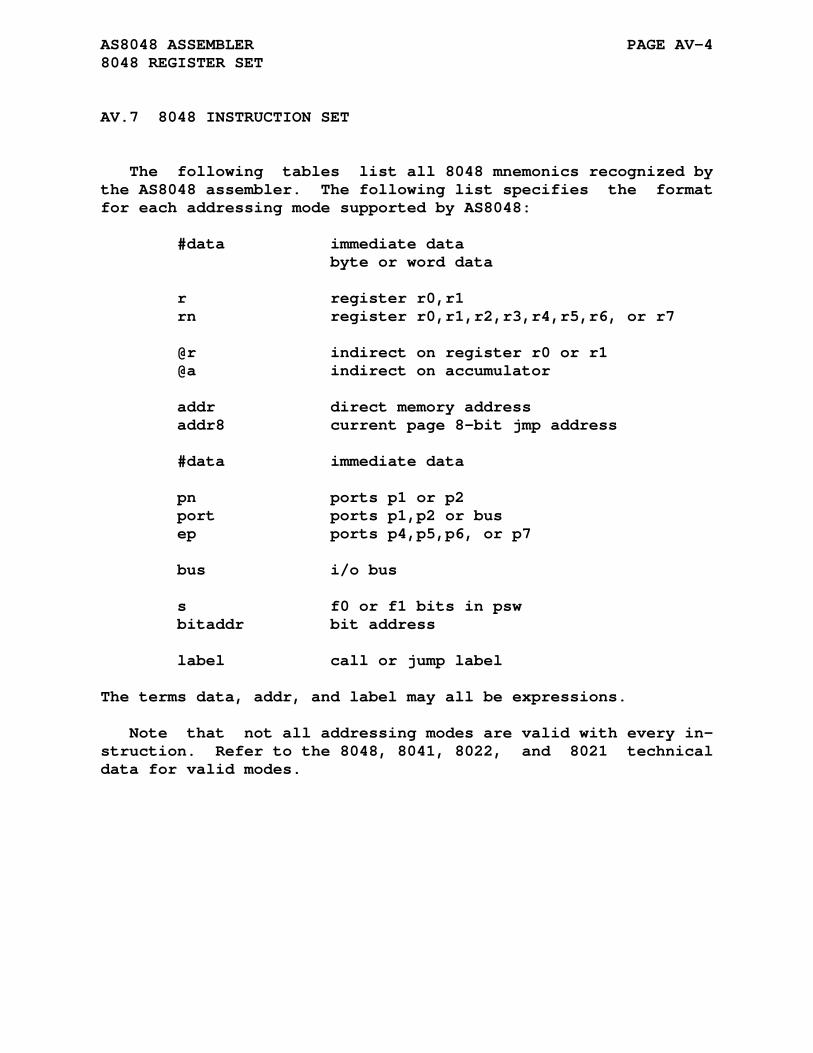
AS8048 ASSEMBLER PAGE AV-4 8048 REGISTER SET
AV.7 8048 INSTRUCTION SET
The following tables list all 8048 mnemonics recognized by the AS8048 assembler. The following list specifies the format for each addressing mode supported by AS8048:
#data immediate data byte or word data r register r0,r1 rn register r0,r1,r2,r3,r4,r5,r6, or r7 @r indirect on register r0 or r1 @a indirect on accumulator addr direct memory address addr8 current page 8-bit jmp address #data immediate data pn ports p1 or p2 port ports p1,p2 or bus ep ports p4,p5,p6, or p7 bus i/o bus s f0 or f1 bits in psw bitaddr bit address label call or jump label
The terms data, addr, and label may all be expressions.
Note that not all addressing modes are valid with every in- struction. Refer to the 8048, 8041, 8022, and 8021 technical data for valid modes.
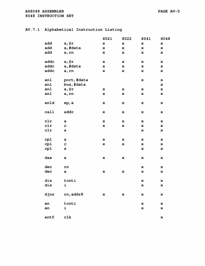
AS8048 ASSEMBLER PAGE AV-5 8048 INSTRUCTION SET
AV.7.1 Alphabetical Instruction Listing
8021 8022 8041 8048 add a,@r x x x x add a,#data x x x x add a,rn x x x x addc a,@r x x x x addc a,#data x x x x addc a,rn x x x x anl port,#data x x anl bus,#data x anl a,@r x x x x anl a,rn x x x x anld ep,a x x x x call addr x x x x clr a x x x x clr c x x x x clr s x x cpl a x x x x cpl c x x x x cpl s x x daa a x x x x dec rn x x dec a x x x x dis tcnti x x dis i x x djnz rn,addr8 x x x x en tcnti x x en i x x ent0 clk x

AS8048 ASSEMBLER PAGE AV-6 8048 INSTRUCTION SET
8021 8022 8041 8048 in a,dbb x in a,pn x x x x inc a x x x x inc a,@r x x inc rn x x x x ins a,bus x jmp addr x x x x jmpp @a x x x x jb0 addr8 x x jb1 addr8 x x jb2 addr8 x x jb3 addr8 x x jb4 addr8 x x jb5 addr8 x x jb6 addr8 x x jb7 addr8 x x jc addr8 x x x x jf0 addr8 x x jf1 addr8 x x jnc addr8 x x x x jni addr8 x jnibf addr8 x jnt0 addr8 x x jnt1 addr8 x x jnz addr8 x x x x jobf addr8 x jtf addr8 x x x x jt0 addr8 x x jt1 addr8 x x x x jz addr8 x x x x

AS8048 ASSEMBLER PAGE AV-7 8048 INSTRUCTION SET
8021 8022 8041 8048 mov a,#data x x x x mov a,psw x x mov a,@r x x x x mov a,rn x x x x mov a,t x x x x mov psw,a x x mov rn,a x x x x mov @r,a x x x x mov rn,#data x x x x mov @r,#data x x x x mov t,a x x x x movd a,ep x x x x movd ep,a x x x movp a,@a x x x x movp3 a,@a x x movx a,@r x movx @r,a x nop x x x orl a,#data x x x x orl a,rn x x x x orl a,@r x x x x orl bus,#data x orl port,#data x x orld ep,a x x x x out dbb,a x outl bus,a x outl port,a x x x x rad a x ret x x x x retr x x

AS8048 ASSEMBLER PAGE AV-8 8048 INSTRUCTION SET
8021 8022 8041 8048 rl a x x x x rlc a x x x x rr a x x x x rrc a x x x x sel an0 x sel an1 x sel mb0 x sel mb1 x sel rb0 x sel rb1 x swap a x x x x stop tcnt x x x x strt cnt x x x x strt t x x x x xch a,@r x x x x xchd a,@r x x x x xrl a,@r x x x x xrl a,#data x x x x xch a,rn x x x x xrl a,rn x x x x

APPENDIX AW
AS8051 ASSEMBLER
AW.1 ACKNOWLEDGMENT
Thanks to John Hartman for his contribution of the AS8051 cross assembler.
John L. Hartman jhartman at compuserve dot com noice at noicedebugger dot com
AW.2 8051 REGISTER SET
The following is a list of the 8051 registers used by AS8051:
a,b - 8-bit accumulators r0,r1,r2,r3 - 8-bit registers r4,r5,r6,r7 dptr - data pointer sp - stack pointer pc - program counter psw - status word c - carry (bit in status word)

AS8051 ASSEMBLER PAGE AW-2 8051 REGISTER SET
AW.3 8051 INSTRUCTION SET
The following tables list all 8051 mnemonics recognized by the AS8051 assembler. The following list specifies the format for each addressing mode supported by AS8051:
#data immediate data byte or word data r,r1,r2 register r0,r1,r2,r3,r4,r5,r6, or r7 @r indirect on register r0 or r1 @dptr indirect on data pointer @a+dptr indirect on accumulator plus data pointer @a+pc indirect on accumulator plus program counter addr direct memory address bitaddr bit address label call or jump label
The terms data, addr, bitaddr, and label may all be expressions.
Note that not all addressing modes are valid with every in- struction. Refer to the 8051 technical data for valid modes.
AW.3.1 Inherent Instructions
nop

AS8051 ASSEMBLER PAGE AW-3 8051 INSTRUCTION SET
AW.3.2 Move Instructions
mov a,#data mov a,addr mov a,r mov a,@r mov r,#data mov r,addr mov r,a mov addr,a mov addr,#data mov addr,r mov addr,@r mov addr1,addr2 mov bitaddr,c mov @r,#data mov @r,addr mov @r,a mov c,bitaddr mov dptr,#data movc a,@a+dptr movc a,@a+pc movx a,@dptr movx a,@r movx @dptr,a movx @r,a
AW.3.3 Single Operand Instructions
clr a clr c clr bitaddr cpl a cpl c cpl bitaddr setb c setb bitaddr da a rr a rrc a rl a rlc a swap a dec a dec r dec @r inc a inc r inc dptr inc @r div ab mul ab pop addr push addr
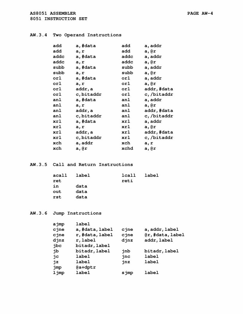
AS8051 ASSEMBLER PAGE AW-4 8051 INSTRUCTION SET
AW.3.4 Two Operand Instructions
add a,#data add a,addr add a,r add a,@r addc a,#data addc a,addr addc a,r addc a,@r subb a,#data subb a,addr subb a,r subb a,@r orl a,#data orl a,addr orl a,r orl a,@r orl addr,a orl addr,#data orl c,bitaddr orl c,/bitaddr anl a,#data anl a,addr anl a,r anl a,@r anl addr,a anl addr,#data anl c,bitaddr anl c,/bitaddr xrl a,#data xrl a,addr xrl a,r xrl a,@r xrl addr,a xrl addr,#data xrl c,bitaddr xrl c,/bitaddr xch a,addr xch a,r xch a,@r xchd a,@r
AW.3.5 Call and Return Instructions
acall label lcall label ret reti in data out data rst data
AW.3.6 Jump Instructions
ajmp label cjne a,#data,label cjne a,addr,label cjne r,#data,label cjne @r,#data,label djnz r,label djnz addr,label jbc bitadr,label jb bitadr,label jnb bitadr,label jc label jnc label jz label jnz label jmp @a+dptr ljmp label sjmp label
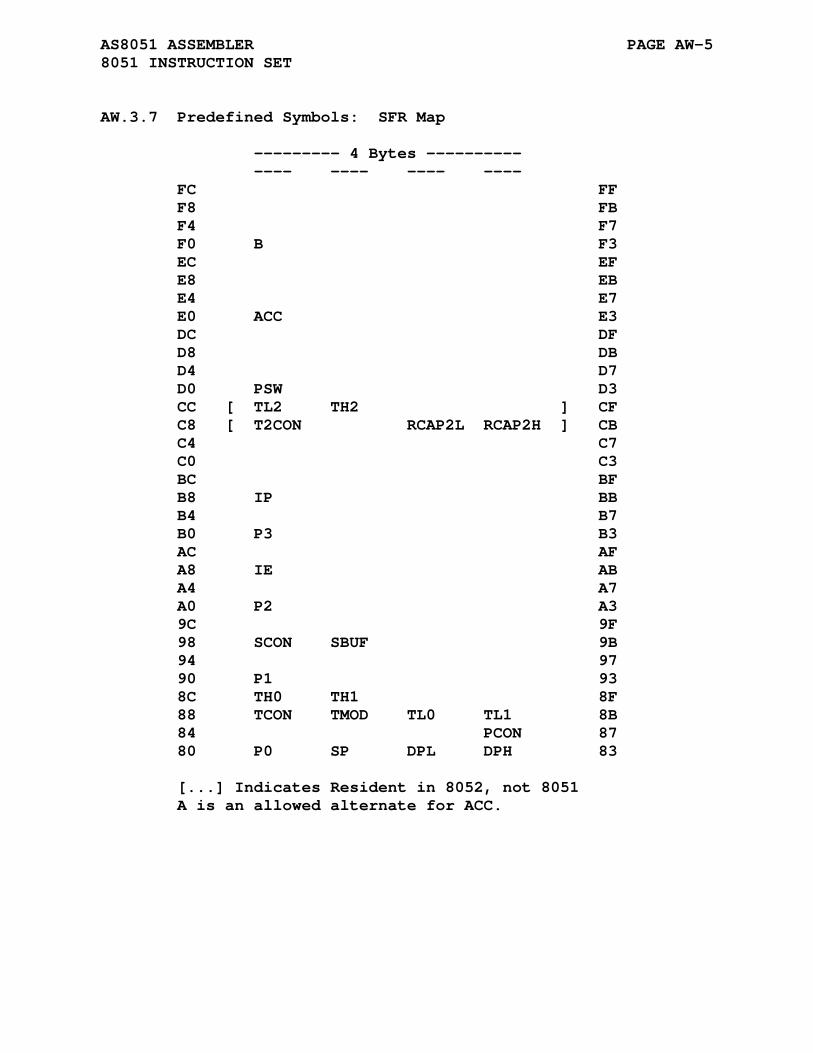
AS8051 ASSEMBLER PAGE AW-5 8051 INSTRUCTION SET
AW.3.7 Predefined Symbols: SFR Map
--------- 4 Bytes ---------- ---- ---- ---- ---- FC FF F8 FB F4 F7 F0 B F3 EC EF E8 EB E4 E7 E0 ACC E3 DC DF D8 DB D4 D7 D0 PSW D3 CC [ TL2 TH2 ] CF C8 [ T2CON RCAP2L RCAP2H ] CB C4 C7 C0 C3 BC BF B8 IP BB B4 B7 B0 P3 B3 AC AF A8 IE AB A4 A7 A0 P2 A3 9C 9F 98 SCON SBUF 9B 94 97 90 P1 93 8C TH0 TH1 8F 88 TCON TMOD TL0 TL1 8B 84 PCON 87 80 P0 SP DPL DPH 83 [...] Indicates Resident in 8052, not 8051 A is an allowed alternate for ACC.

AS8051 ASSEMBLER PAGE AW-6 8051 INSTRUCTION SET
AW.3.8 Predefined Symbols: SFR Bit Addresses
---------- 4 BITS ---------- ---- ---- ---- ---- FC FF F8 FB F4 B.4 B.5 B.6 B.7 F7 F0 B.0 B.1 B.2 B.3 F3 EC EF E8 EB E4 ACC.4 ACC.5 ACC.6 ACC.7 E7 E0 ACC.0 ACC.1 ACC.2 ACC.3 E3 DC DF D8 DB D4 PSW.4 PSW.5 PSW.6 PSW.7 D7 D0 PSW.0 PSW.1 PSW.2 PSW.3 D3 CC [ T2CON.4 T2CON.5 T2CON.6 T2CON.7 ] CF C8 [ T2CON.0 T2CON.1 T2CON.2 T2CON.3 ] CB C4 C7 C0 C3 BC IP.4 IP.5 IP.6 IP.7 BF B8 IP.0 IP.1 IP.2 IP.3 BB B4 P3.4 P3.5 P3.6 P3.7 B7 B0 P3.0 P3.1 P3.2 P3.3 B3 AC IE.4 IE.5 EI.6 IE.7 AF A8 IE.0 IE.1 IE.2 IE.3 AB A4 P2.4 P2.5 P2.6 P2.7 A7 A0 P2.0 P2.1 P2.2 P2.3 A3 9C SCON.4 SCON.5 SCON.6 SCON.7 9F 98 SCON.0 SCON.1 SCON.2 SCON.3 9B 94 P1.4 P1.5 P1.6 P1.7 97 90 P1.0 P1.1 P1.2 P1.3 93 8C TCON.4 TCON.5 TCON.6 TCON.7 8F 88 TCON.0 TCON.1 TCON.2 TCON.3 8B 84 P0.4 P0.5 P0.6 P0.7 87 80 P0.0 P0.1 P0.2 P0.3 83 [...] Indicates Resident in 8052, not 8051 A is an allowed alternate for ACC.

AS8051 ASSEMBLER PAGE AW-7 8051 INSTRUCTION SET
AW.3.9 Predefined Symbols: Control Bits
---------- 4 BITS ---------- ---- ---- ---- ---- FC FF F8 FB F4 F7 F0 F3 EC EF E8 EB E4 E7 E0 E3 DC DF D8 DB D4 RS1 F0 AC CY D7 D0 P OV RS0 D3 CC [ TLCK RCLK EXF2 TF2 ] CF C8 [ CPRL2 CT2 TR2 EXEN2 ] CB C4 C7 C0 C3 BC PS PT2 BF B8 PX0 PT0 PX1 PT1 BB B4 B7 B0 RXD TXD INT0 INT1 B3 AC ES ET2 EA AF A8 EX0 ET0 EX1 ET1 AB A4 A7 A0 A3 9C REN SM2 SM1 SM0 9F 98 RI TI RB8 TB8 9B 94 97 90 93 8C TR0 TF0 TR1 TF1 8F 88 IT0 IE0 IT1 IE1 8B 84 87 80 83 [...] Indicates Resident in 8052, not 8051

APPENDIX AX
AS8085 ASSEMBLER
AX.1 8085 REGISTER SET
The following is a list of the 8080/8085 registers used by AS8085:
a,b,c,d,e,h,l - 8-bit accumulators m - memory through (hl) sp - stack pointer psw - status word
AX.2 8085 INSTRUCTION SET
The following tables list all 8080/8085 mnemonics recognized by the AS8085 assembler. The following list specifies the format for each addressing mode supported by AS8085:
#data immediate data byte or word data r,r1,r2 register or register pair psw,a,b,c,d,e,h,l bc,de,hl,sp,pc m memory address using (hl) addr direct memory addressing label call or jump label
The terms data, m, addr, and label may be expressions.
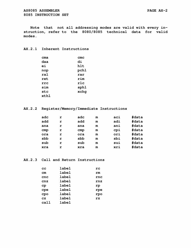
AS8085 ASSEMBLER PAGE AX-2 8085 INSTRUCTION SET
Note that not all addressing modes are valid with every in- struction, refer to the 8080/8085 technical data for valid modes.
AX.2.1 Inherent Instructions
cma cmc daa di ei hlt nop pchl ral rar ret rim rrc rlc sim sphl stc xchg xthl
AX.2.2 Register/Memory/Immediate Instructions
adc r adc m aci #data add r add m adi #data ana r ana m ani #data cmp r cmp m cpi #data ora r ora m ori #data sbb r sbb m sbi #data sub r sub m sui #data xra r xra m xri #data
AX.2.3 Call and Return Instructions
cc label rc cm label rm cnc label rnc cnz label rnz cp label rp cpe label rpe cpo label rpo cz label rz call label
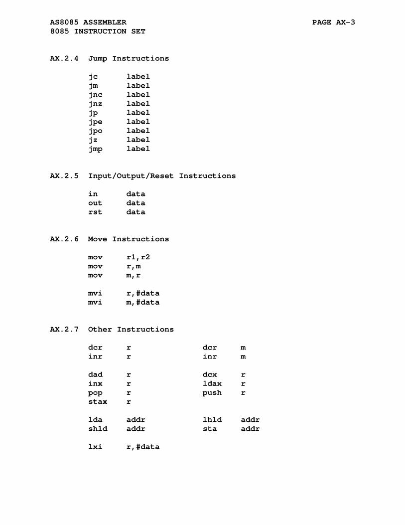
AS8085 ASSEMBLER PAGE AX-3 8085 INSTRUCTION SET
AX.2.4 Jump Instructions
jc label jm label jnc label jnz label jp label jpe label jpo label jz label jmp label
AX.2.5 Input/Output/Reset Instructions
in data out data rst data
AX.2.6 Move Instructions
mov r1,r2 mov r,m mov m,r mvi r,#data mvi m,#data
AX.2.7 Other Instructions
dcr r dcr m inr r inr m dad r dcx r inx r ldax r pop r push r stax r lda addr lhld addr shld addr sta addr lxi r,#data

AS8085 ASSEMBLER PAGE AX-4 8085 INSTRUCTION SET
AX.2.8 Unspecified Instructions
arhl dsub jnx5 addr jx5 addr ldhi #data ldsi #data lhlx rdel rstv shlx

AS8085 ASSEMBLER PAGE AX-5 8085 INSTRUCTION SET
AX.3 UNSPECIFIED OPCODE ARTICLE
Engineer's Notebook, "Electronics" magazine, 1980 ---------------------------- Unspecified 8085 Op Codes Enhance Programming by Wolfgang Dehnhardt and Villy M. Sorenson GSI, Dermstat, and Sorenson Software, Seeheim, West Germany ----------------------------
Ten operating codes and two flag bits previously unknown to most users of the 8085 microprocessor will enable programmers to write more efficient routines. The new members of the instruc- tion set, which were stumbled upon during the testing of an assembler-disassembler module, include seven opcodes that in- volve the processing of register pairs, two that involve jump operations with one new flag, and one that performs a condi- tional restart on the overflow indication of the other flag bit.
The seven register pair instructions (all with 16-bit operands) consist of a double subtraction, a rotate, a shift, indirect loading and storing of a word, and two offset opera- tions. Either BC, DE, HL, or SP are the designated register pairs used in these opcodes.
The mnemonic names of the instructions have been selected to be compatible with the 8085's existing mnemonics. In the double subtraction (DSUB), register pair BC is subtracted from HL. This instruction thus performs the opposite task of DAD B, a well-known instruction. The instruction RDEL rotates register pair DE left 1 bit through the carry. ARHL is an arithmetic shift to the right of HL. It serves to divide HL by 2, except in cases where HL is -1.
All 16 bits of register pair HL can be stored indirectly at the address contained in the DE pair by specifying instruction SHLX. To load HL, LHLX must be employed.

AS8085 ASSEMBLER PAGE AX-6 UNSPECIFIED OPCODE ARTICLE
As an example of how this instruction can be used to cut in- struction steps, consider the common sequence used for a routine table jump shown in part (a) of the figure. By assigning the register DE for HL and using the LHLX instruction, this sequence can be replaced by the much simpler arrangement shown at the bottom of part (a).
As for adding the contents of register pairs with an addi- tional byte (offset), DE can be loaded with HL plus the byte by selecting the instruction LDHI, which simplifies array address- ing. Usually, the architecture of the 8080-type systems dictate addressing of arrays in what are called pages of 256 bytes. This restriction means that the starting address of an array must be placed near the beginning of a page. A typical call is shown in part (b) of the figure.
The page limitation is by passed using th LDHI instruction code and constant indexes. The starting address of the array can now be placed anywhere, and addressing occurs as shown at the bottom of part (b).
An additional byte can be combined with register pair SP in DE if instruction LDSI is specified. This instruction is designed for operating system routines that transfer arguments on the stack. An example sequence, shown in (c), stores HL into a 16-bit word located as the second item below the top of the stack.
The jump and restart instructions work in conjunction with the two discoverd flag bits, X5 and V. Op codes JX5 and JNX5 jump depending on the state of th X5 flag. Op code RSTV makes a restart call to hexidecimal address 40 if the V flag is set; otherwise it functions as a no-operation instruction.
Flag bit V indicates a 2's complement overflow condition for 8- and 16-bit arithmetic operations. Flag bit X5 has been named for its position in the condition code byte and not for its function. It does not resemble any normal flag bit. The only use for this bit found thus far are as an unsigned overflow in- dicator resulting from a data change of FFFF to 0000 on execut- ing DCX.
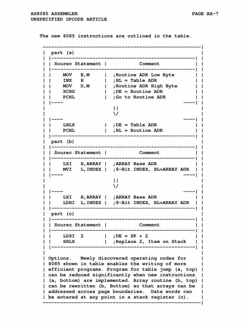
AS8085 ASSEMBLER PAGE AX-7 UNSPECIFIED OPCODE ARTICLE
The new 8085 instructions are outlined in the table. ------------------------------------------------------| | part (a) | | |-------------------------------------------------| | | | Sourec Statement | Comment | | | |-------------------------------------------------| | | | MOV E,M | ;Routine ADR Low Byte | | | | INX H | ;HL = Table ADR | | | | MOV D,M | ;Routine ADR High Byte | | | | XCHG | ;DE = Routine ADR | | | | PCHL | ;Go to Routine ADR | | | |---- ----| | | || | | \/ | | |---- ----| | | | LHLX | ;DE = Table ADR | | | | PCHL | ;HL = Routine ADR | | | |-------------------------------------------------| | | part (b) | | |-------------------------------------------------| | | | Sourec Statement | Comment | | | |-------------------------------------------------| | | | LXI H,ARRAY | ;ARRAY Base ADR | | | | MVI L,INDEX | ;8-Bit INDEX, HL=ARRAY ADR | | | |---- ----| | | || | | \/ | | |---- ----| | | | LXI H,ARRAY | ;ARRAY Base ADR | | | | LDHI L,INDEX | ;8-Bit INDEX, HL=ARRAY ADR | | | |-------------------------------------------------| | | part (c) | | |-------------------------------------------------| | | | Sourec Statement | Comment | | | |-------------------------------------------------| | | | LDSI 2 | ;DE = SP + 2 | | | | SHLX | ;Replace 2, Item on Stack | | | |-------------------------------------------------| | | | | Options. Newly discovered operating codes for | | 8085 shown in table enables the writing of more | | efficient programs. Program for table jump (a, top) | | can be reduced significantly when new instructions | | (a, bottom) are implemented. Array routine (b, top) | | can be rewritten (b, Bottom) so that arrays can be | | addressed across page boundaries. Data words can | | be entered at any point in a stack register (c). | ------------------------------------------------------|
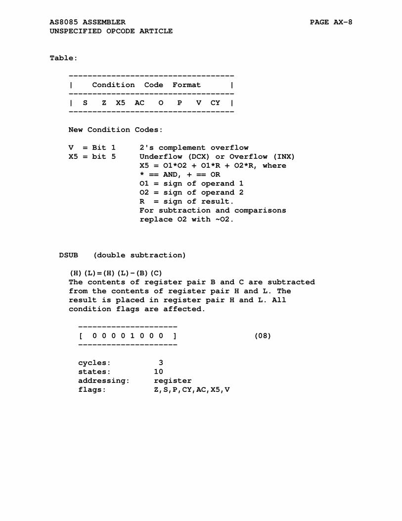
AS8085 ASSEMBLER PAGE AX-8 UNSPECIFIED OPCODE ARTICLE
Table: ----------------------------------- | Condition Code Format | ----------------------------------- | S Z X5 AC O P V CY | ----------------------------------- New Condition Codes: V = Bit 1 2's complement overflow X5 = bit 5 Underflow (DCX) or Overflow (INX) X5 = O1*O2 + O1*R + O2*R, where * == AND, + == OR O1 = sign of operand 1 O2 = sign of operand 2 R = sign of result. For subtraction and comparisons replace O2 with ~O2. DSUB (double subtraction) (H)(L)=(H)(L)-(B)(C) The contents of register pair B and C are subtracted from the contents of register pair H and L. The result is placed in register pair H and L. All condition flags are affected. --------------------- [ 0 0 0 0 1 0 0 0 ] (08) --------------------- cycles: 3 states: 10 addressing: register flags: Z,S,P,CY,AC,X5,V

AS8085 ASSEMBLER PAGE AX-9 UNSPECIFIED OPCODE ARTICLE
ARHL (arithmetic shift of H and L to the right) (H7=H7);(Hn-1)=(Hn) (L7=H0);(Ln-1)=(Ln);(CY)=(L0) The contents of register pair H and L are shifted right one bit. The uppermost bit is duplicated and the lowest bit is shifted into the carry bit. The result is placed in register pair H and L. Note: only the CY flag is affected. --------------------- [ 0 0 0 1 0 0 0 0 ] (10) --------------------- cycles: 3 states: 7 addressing: register flags: CY RDEL (rotate D and E left through carry) (Dn+1)=(Dn);(D0)=(E7) (CY)=(D7);(En+1)=(En);(E0)=(CY) The contents of register pair D and E are rotated left one position through the carry flag. The low order bit is set equal to the CY flag and the CY flag is set to the value shifted out of the high-order bit. Only the CY and V flags are affected. --------------------- [ 0 0 0 1 1 0 0 0 ] (18) --------------------- cycles: 3 states: 10 addressing: register flags: CY, V
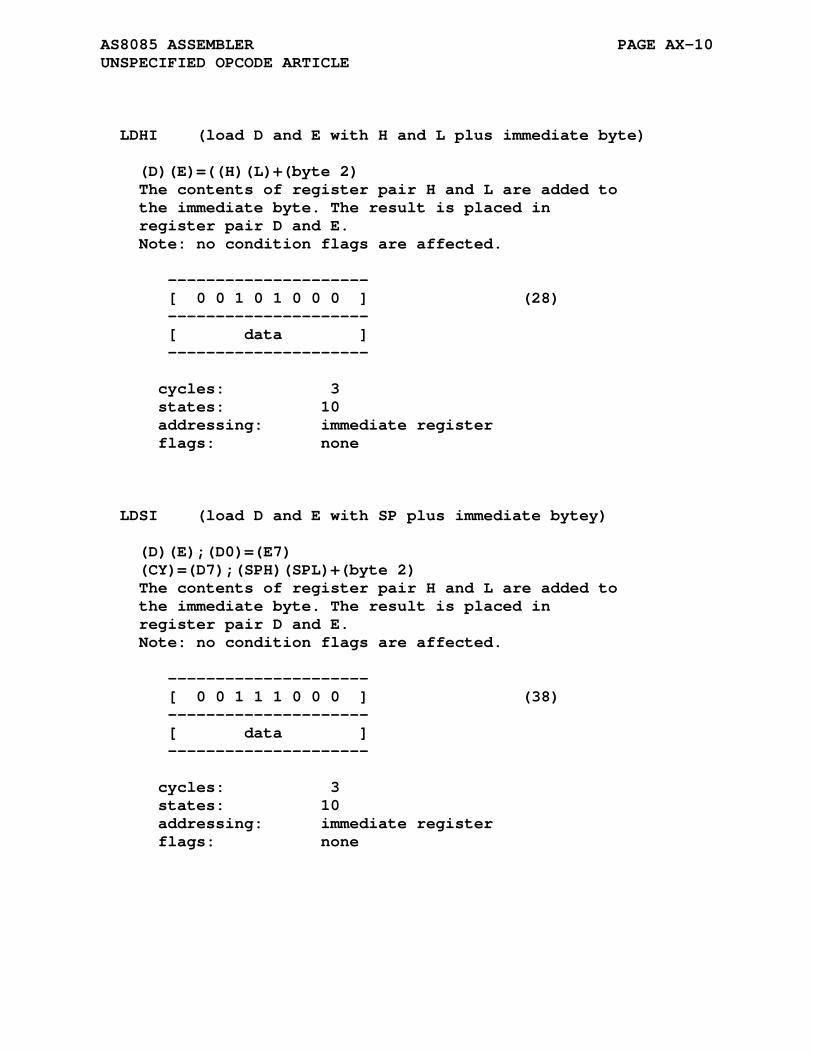
AS8085 ASSEMBLER PAGE AX-10 UNSPECIFIED OPCODE ARTICLE
LDHI (load D and E with H and L plus immediate byte) (D)(E)=((H)(L)+(byte 2) The contents of register pair H and L are added to the immediate byte. The result is placed in register pair D and E. Note: no condition flags are affected. --------------------- [ 0 0 1 0 1 0 0 0 ] (28) --------------------- [ data ] --------------------- cycles: 3 states: 10 addressing: immediate register flags: none LDSI (load D and E with SP plus immediate bytey) (D)(E);(D0)=(E7) (CY)=(D7);(SPH)(SPL)+(byte 2) The contents of register pair H and L are added to the immediate byte. The result is placed in register pair D and E. Note: no condition flags are affected. --------------------- [ 0 0 1 1 1 0 0 0 ] (38) --------------------- [ data ] --------------------- cycles: 3 states: 10 addressing: immediate register flags: none
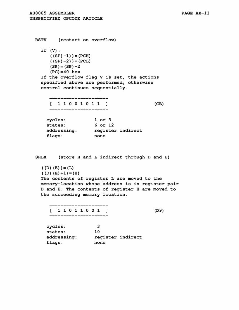
AS8085 ASSEMBLER PAGE AX-11 UNSPECIFIED OPCODE ARTICLE
RSTV (restart on overflow) if (V): ((SP)-1))=(PCH) ((SP)-2))=(PCL) (SP)=(SP)-2 (PC)=40 hex If the overflow flag V is set, the actions specified above are performed; otherwise control continues sequentially. --------------------- [ 1 1 0 0 1 0 1 1 ] (CB) --------------------- cycles: 1 or 3 states: 6 or 12 addressing: register indirect flags: none SHLX (store H and L indirect through D and E) ((D)(E))=(L) ((D)(E)+1)=(H) The contents of register L are moved to the memory-location whose address is in register pair D and E. The contents of register H are moved to the succeeding memory location. --------------------- [ 1 1 0 1 1 0 0 1 ] (D9) --------------------- cycles: 3 states: 10 addressing: register indirect flags: none
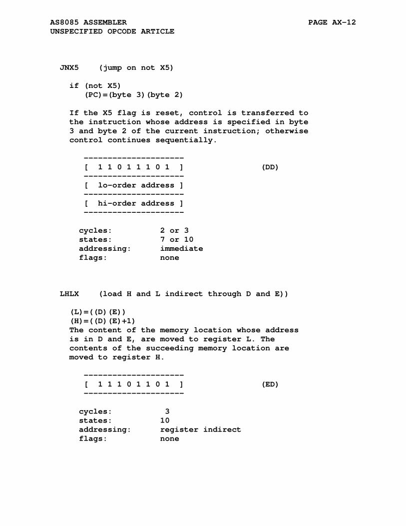
AS8085 ASSEMBLER PAGE AX-12 UNSPECIFIED OPCODE ARTICLE
JNX5 (jump on not X5) if (not X5) (PC)=(byte 3)(byte 2) If the X5 flag is reset, control is transferred to the instruction whose address is specified in byte 3 and byte 2 of the current instruction; otherwise control continues sequentially. --------------------- [ 1 1 0 1 1 1 0 1 ] (DD) --------------------- [ lo-order address ] --------------------- [ hi-order address ] --------------------- cycles: 2 or 3 states: 7 or 10 addressing: immediate flags: none LHLX (load H and L indirect through D and E)) (L)=((D)(E)) (H)=((D)(E)+1) The content of the memory location whose address is in D and E, are moved to register L. The contents of the succeeding memory location are moved to register H. --------------------- [ 1 1 1 0 1 1 0 1 ] (ED) --------------------- cycles: 3 states: 10 addressing: register indirect flags: none
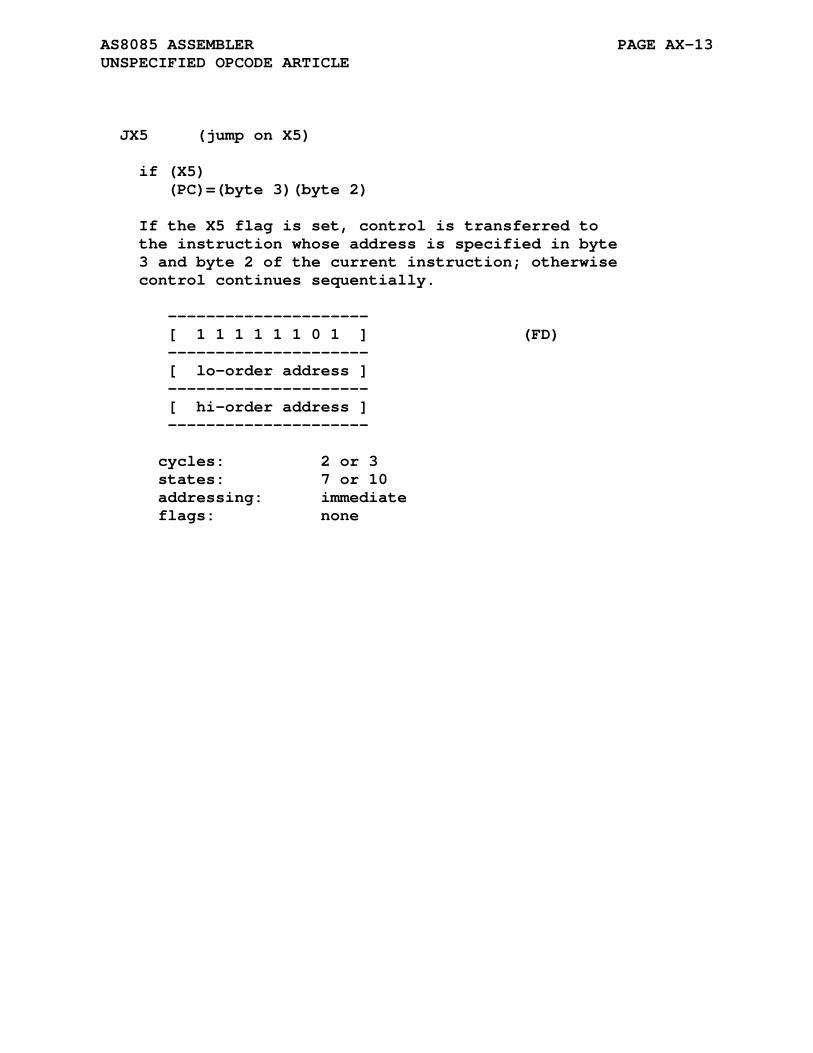
AS8085 ASSEMBLER PAGE AX-13 UNSPECIFIED OPCODE ARTICLE
JX5 (jump on X5) if (X5) (PC)=(byte 3)(byte 2) If the X5 flag is set, control is transferred to the instruction whose address is specified in byte 3 and byte 2 of the current instruction; otherwise control continues sequentially. --------------------- [ 1 1 1 1 1 1 0 1 ] (FD) --------------------- [ lo-order address ] --------------------- [ hi-order address ] --------------------- cycles: 2 or 3 states: 7 or 10 addressing: immediate flags: none

APPENDIX AY
AS8X300 ASSEMBLER
The AS8X300 assembler supports the 8X300 and 8X305 microcon- trollers with the basic syntax of the MCCAP Microcontroller Cross Assembler Program. The 8x300 microcontroller has just eight basic instructions, MOVE, ADD, AND, XOR, XMIT, NZT, XEC, and JMP. The 8x305 has two addition instruction mnemonics, XML and XMR. Three additional mnemonics are common to the 8X300 and 8X305, HALT, NOP, and SEL. These five instructions are derived from the basic instructions.
The CALL and RTN functionalities are provided by macros con- tained in the s8xmcros.asm macro library. These functions and others in the library will be discussed in the following sec- tions.
AY.1 PROCESSOR SPECIFIC DIRECTIVES
AY.1.1 .8x300 Directive
Format:
.8x300
The default microcontroller selection is the 8x300. The .8x300 directive explicitly selects coding for the 8x300 microcon- troller.
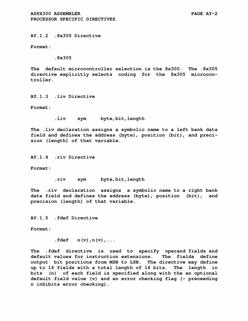
AS8X300 ASSEMBLER PAGE AY-2 PROCESSOR SPECIFIC DIRECTIVES
AY.1.2 .8x305 Directive
Format:
.8x305
The default microcontroller selection is the 8x300. The .8x305 directive explicitly selects coding for the 8x305 microcon- troller.
AY.1.3 .liv Directive
Format:
.liv sym byte,bit,length
The .liv declaration assigns a symbolic name to a left bank data field and defines the address (byte), position (bit), and preci- sion (length) of that variable.
AY.1.4 .riv Directive
Format:
.riv sym byte,bit,length
The .riv declaration assigns a symbolic name to a right bank data field and defines the address (byte), position (bit), and precision (length) of that variable.
AY.1.5 .fdef Directive
Format:
.fdef n(v),n(v),...
The .fdef directive is used to specify operand fields and default values for instruction extensions. The fields define output bit positions from MSB to LSB. The directive may define up to 16 fields with a total length of 16 bits. The length in bits (n) of each field is specified along with the an optional default field value (v) and an error checking flag (- preceeding n inhibits error checking).
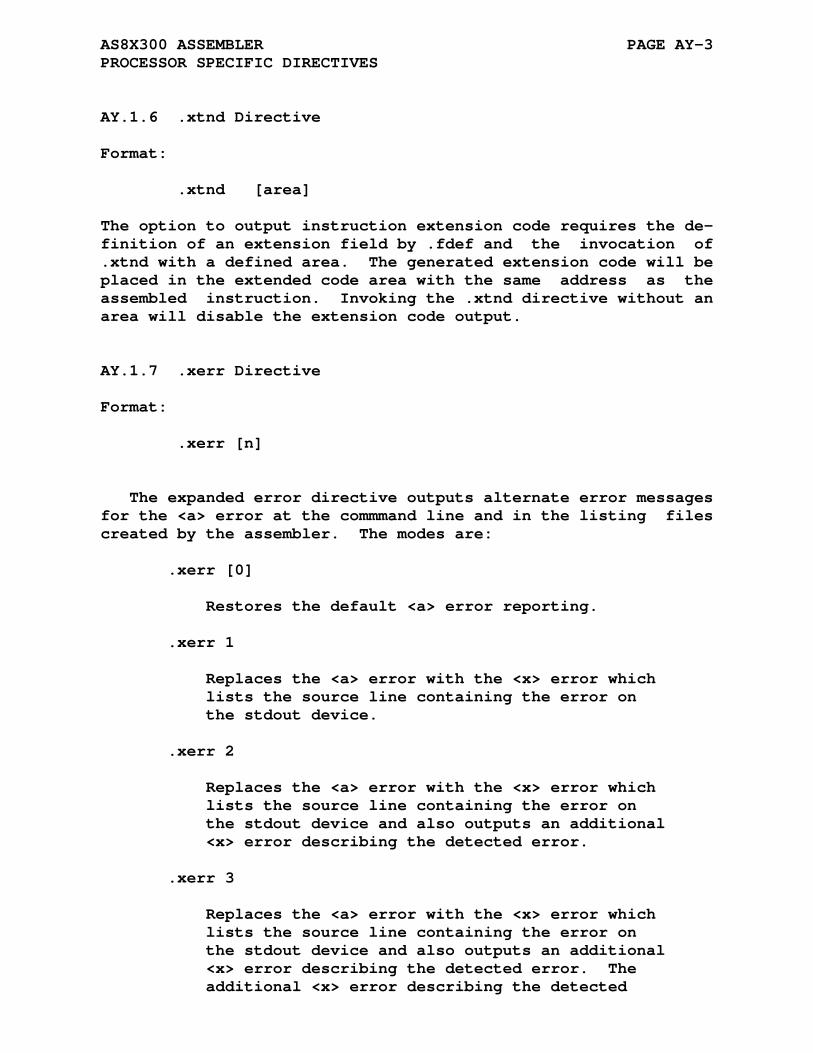
AS8X300 ASSEMBLER PAGE AY-3 PROCESSOR SPECIFIC DIRECTIVES
AY.1.6 .xtnd Directive
Format:
.xtnd [area]
The option to output instruction extension code requires the de- finition of an extension field by .fdef and the invocation of .xtnd with a defined area. The generated extension code will be placed in the extended code area with the same address as the assembled instruction. Invoking the .xtnd directive without an area will disable the extension code output.
AY.1.7 .xerr Directive
Format:
.xerr [n]
The expanded error directive outputs alternate error messages for the <a> error at the commmand line and in the listing files created by the assembler. The modes are:
.xerr [0] Restores the default <a> error reporting. .xerr 1 Replaces the <a> error with the <x> error which lists the source line containing the error on the stdout device. .xerr 2 Replaces the <a> error with the <x> error which lists the source line containing the error on the stdout device and also outputs an additional <x> error describing the detected error. .xerr 3 Replaces the <a> error with the <x> error which lists the source line containing the error on the stdout device and also outputs an additional <x> error describing the detected error. The additional <x> error describing the detected

AS8X300 ASSEMBLER PAGE AY-4 PROCESSOR SPECIFIC DIRECTIVES
error is inserted into the optional listing file.
AY.2 THE 8X300/8X305 MACRO LIBRARY
The macro library, s8xmcros.asm, contains macros defining functionality not implemented directly into the assembler.
The macros are:
ORG space, pgsize ^/[...]/ PROC sub ENTRY sub CALL sub ^/[...]/ RTN ^/[...]/ CALL_TABLE area_c, area_x ^/[...]/
Where the ^/[...]/ syntax passes the string "[...]" as an argu- ment of the macro.
AY.2.1 ORG
Format:
ORG space, pgsize ^/[...]/
The ORG macro changes the value of the location counter either conditionally or unconditionally. The first form of the ORG macro:
ORG address
unconditionally changes the value of the location counter to the value indicated by "address" which is any constant, symbol or expression which evaluates to a value between 1 and 8191.
The second form of the ORG macro conditionally sets the loca- tion counter to the next page or segment boundary if there are insufficient locations (space) in the current page (pgsize = 32) or segment (pgsize = 256). If there is insufficient space then a jump instruction is inserted pointing to the next page/segment boundary.
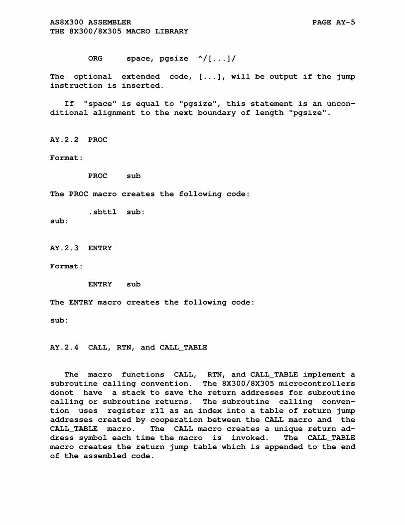
AS8X300 ASSEMBLER PAGE AY-5 THE 8X300/8X305 MACRO LIBRARY
ORG space, pgsize ^/[...]/
The optional extended code, [...], will be output if the jump instruction is inserted.
If "space" is equal to "pgsize", this statement is an uncon- ditional alignment to the next boundary of length "pgsize".
AY.2.2 PROC
Format:
PROC sub
The PROC macro creates the following code:
.sbttl sub: sub:
AY.2.3 ENTRY
Format:
ENTRY sub
The ENTRY macro creates the following code:
sub:
AY.2.4 CALL, RTN, and CALL_TABLE
The macro functions CALL, RTN, and CALL_TABLE implement a subroutine calling convention. The 8X300/8X305 microcontrollers donot have a stack to save the return addresses for subroutine calling or subroutine returns. The subroutine calling conven- tion uses register r11 as an index into a table of return jump addresses created by cooperation between the CALL macro and the CALL_TABLE macro. The CALL macro creates a unique return ad- dress symbol each time the macro is invoked. The CALL_TABLE macro creates the return jump table which is appended to the end of the assembled code.

AS8X300 ASSEMBLER PAGE AY-6 THE 8X300/8X305 MACRO LIBRARY
Format:
CALL sub ^/[...]/
The CALL macro creates the following code:
xmit n,r11 [...] jmp sub [...]
and a symbol, .rtn.n which points to the instruction following the inserted code, where n is 0 for the first CALL invocation and is incremented by 1 for each successive CALL invocation. The extended instruction code, [...], is optional.
Format:
RTN ^/[...]/
The RTN macro creates the following code:
jmp .tbgn. [...]
where .tbgn. is a label created by the macro CALL_TABLE when invoked at the end of the assembly. The table return index, r11, will select the proper return jump address entry from the jump table created by the CALL_TABLE macro. The extended in- struction code, [...], is optional.
Format:
CALL_TABLE area_c,area_x ^/[...]/
'area_c' specifies the code area where the return jump table is to be placed. 'area_x' specifies the code area where the exten- sion data is to be placed. CALL_TABLE can be invoked with no arguments to use the current code and extension areas and the default extended code. To create an empty argument use the con- struct ^// for the argument.
The CALL_TABLE macro creates an entry for each CALL macro in- voked in the assembly program and produces the following code:
xec .+1(r11) [...] jmp .rtn.0 [...] jmp .rtn.1 [...] jmp .rtn.2 [...] ... repeating for the total number of CALLs

AS8X300 ASSEMBLER PAGE AY-7 8X300 AND 8X305 REGISTER SETS
AY.3 8X300 AND 8X305 REGISTER SETS
The following is a list of the 8X300 and 8X305 registers used by AS8X300:
Registers Common To The 8X300 and 8X305 r0,r1,r2,r3 - 8-bit registers r4,r5,r6,r7 r10,r11 aux (= r0) ivl (= r7) ovf (= r10) ivr (= r17) Additional Registers Of The 8X305 r12,r13,r14, - 8-bit registers r15,r16 Register names containing multiple letters must be all lower case or all upper case.
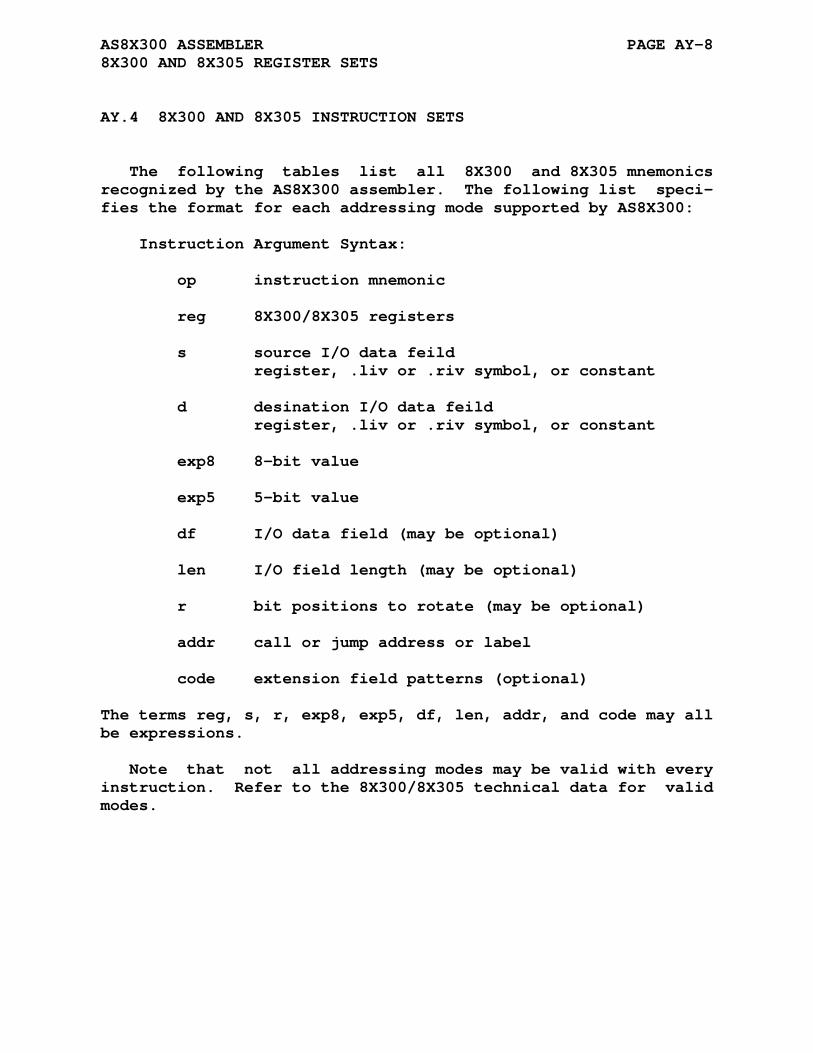
AS8X300 ASSEMBLER PAGE AY-8 8X300 AND 8X305 REGISTER SETS
AY.4 8X300 AND 8X305 INSTRUCTION SETS
The following tables list all 8X300 and 8X305 mnemonics recognized by the AS8X300 assembler. The following list speci- fies the format for each addressing mode supported by AS8X300:
Instruction Argument Syntax: op instruction mnemonic reg 8X300/8X305 registers s source I/O data feild register, .liv or .riv symbol, or constant d desination I/O data feild register, .liv or .riv symbol, or constant exp8 8-bit value exp5 5-bit value df I/O data field (may be optional) len I/O field length (may be optional) r bit positions to rotate (may be optional) addr call or jump address or label code extension field patterns (optional)
The terms reg, s, r, exp8, exp5, df, len, addr, and code may all be expressions.
Note that not all addressing modes may be valid with every instruction. Refer to the 8X300/8X305 technical data for valid modes.

AS8X300 ASSEMBLER PAGE AY-9 8X300 AND 8X305 INSTRUCTION SETS
AY.4.1 Instruction Listing
Basic 8X300 and 8X305 Instructions MOVE, ADD, AND, XOR - Data Manipulation op s,d [code] op s(r),d [code] op s,len,d [code] XMIT - Load Immediate XMIT exp8,reg [code] XMIT exp5,df,len [code] XDEF - Execute XEC exp8(reg),size [code] XEC exp5(df,len),size [code] NZT - Non-Zero Transfer NZT reg,exp8 [code] NZT df,len,exp5 [code] JMP - Unconditional Jump JMP addr [code] Aditional 8X305 Instructions XML, XMR - Load Immediate To Left Or Right Bank op immed [code] Common Derived Instructions SEL, HALT, NOP - Derived Instructions SEL df [code] HALT [code] NOP [code]
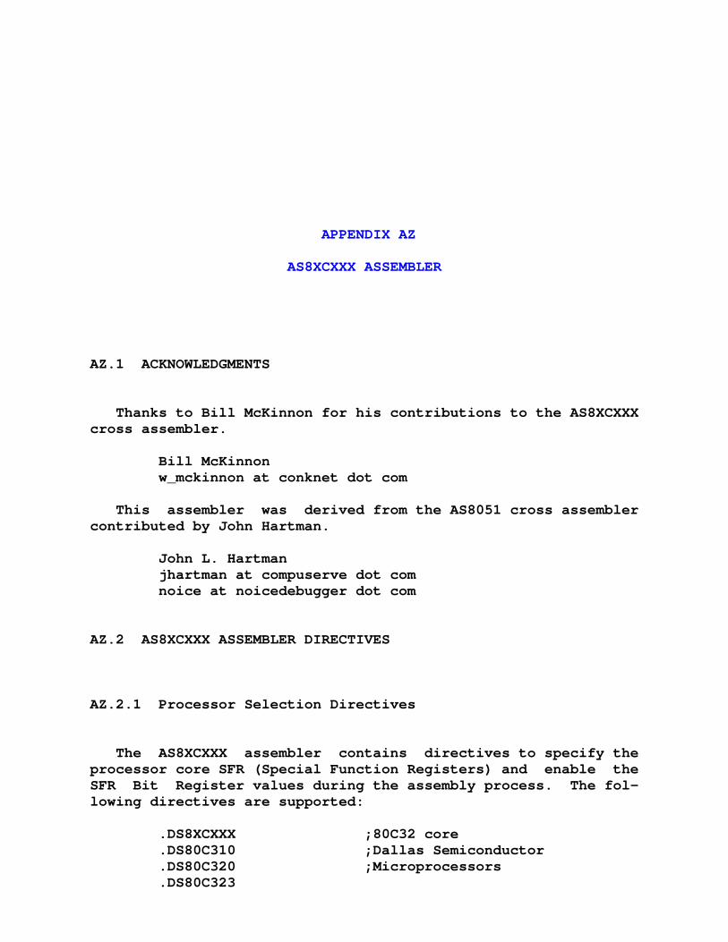
APPENDIX AZ
AS8XCXXX ASSEMBLER
AZ.1 ACKNOWLEDGMENTS
Thanks to Bill McKinnon for his contributions to the AS8XCXXX cross assembler.
Bill McKinnon w_mckinnon at conknet dot com
This assembler was derived from the AS8051 cross assembler contributed by John Hartman.
John L. Hartman jhartman at compuserve dot com noice at noicedebugger dot com
AZ.2 AS8XCXXX ASSEMBLER DIRECTIVES
AZ.2.1 Processor Selection Directives
The AS8XCXXX assembler contains directives to specify the processor core SFR (Special Function Registers) and enable the SFR Bit Register values during the assembly process. The fol- lowing directives are supported:
.DS8XCXXX ;80C32 core .DS80C310 ;Dallas Semiconductor .DS80C320 ;Microprocessors .DS80C323
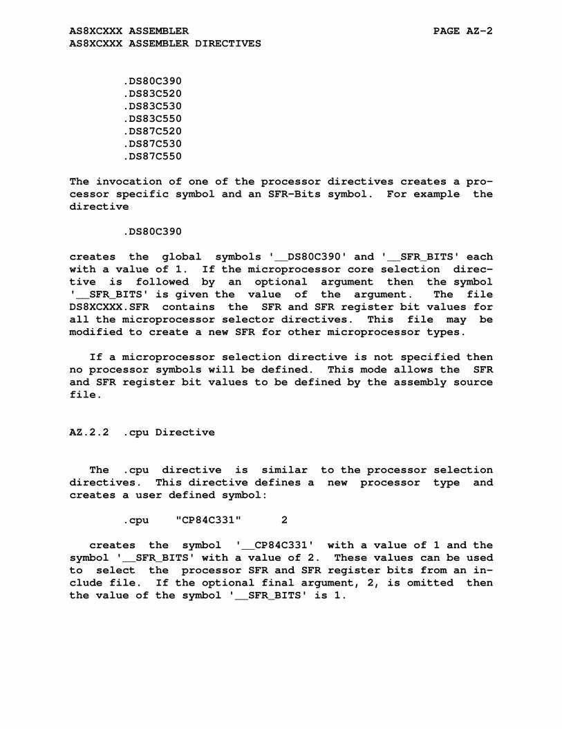
AS8XCXXX ASSEMBLER PAGE AZ-2 AS8XCXXX ASSEMBLER DIRECTIVES
.DS80C390 .DS83C520 .DS83C530 .DS83C550 .DS87C520 .DS87C530 .DS87C550
The invocation of one of the processor directives creates a pro- cessor specific symbol and an SFR-Bits symbol. For example the directive
.DS80C390
creates the global symbols '__DS80C390' and '__SFR_BITS' each with a value of 1. If the microprocessor core selection direc- tive is followed by an optional argument then the symbol '__SFR_BITS' is given the value of the argument. The file DS8XCXXX.SFR contains the SFR and SFR register bit values for all the microprocessor selector directives. This file may be modified to create a new SFR for other microprocessor types.
If a microprocessor selection directive is not specified then no processor symbols will be defined. This mode allows the SFR and SFR register bit values to be defined by the assembly source file.
AZ.2.2 .cpu Directive
The .cpu directive is similar to the processor selection directives. This directive defines a new processor type and creates a user defined symbol:
.cpu "CP84C331" 2
creates the symbol '__CP84C331' with a value of 1 and the symbol '__SFR_BITS' with a value of 2. These values can be used to select the processor SFR and SFR register bits from an in- clude file. If the optional final argument, 2, is omitted then the value of the symbol '__SFR_BITS' is 1.
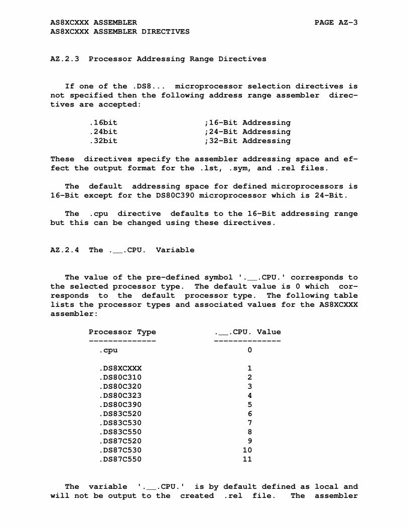
AS8XCXXX ASSEMBLER PAGE AZ-3 AS8XCXXX ASSEMBLER DIRECTIVES
AZ.2.3 Processor Addressing Range Directives
If one of the .DS8... microprocessor selection directives is not specified then the following address range assembler direc- tives are accepted:
.16bit ;16-Bit Addressing .24bit ;24-Bit Addressing .32bit ;32-Bit Addressing
These directives specify the assembler addressing space and ef- fect the output format for the .lst, .sym, and .rel files.
The default addressing space for defined microprocessors is 16-Bit except for the DS80C390 microprocessor which is 24-Bit.
The .cpu directive defaults to the 16-Bit addressing range but this can be changed using these directives.
AZ.2.4 The .__.CPU. Variable
The value of the pre-defined symbol '.__.CPU.' corresponds to the selected processor type. The default value is 0 which cor- responds to the default processor type. The following table lists the processor types and associated values for the AS8XCXXX assembler:
Processor Type .__.CPU. Value -------------- -------------- .cpu 0 .DS8XCXXX 1 .DS80C310 2 .DS80C320 3 .DS80C323 4 .DS80C390 5 .DS83C520 6 .DS83C530 7 .DS83C550 8 .DS87C520 9 .DS87C530 10 .DS87C550 11
The variable '.__.CPU.' is by default defined as local and will not be output to the created .rel file. The assembler

AS8XCXXX ASSEMBLER PAGE AZ-4 AS8XCXXX ASSEMBLER DIRECTIVES
command line options -g or -a will not cause the local symbol to be output to the created .rel file.
The assembler .globl directive may be used to change the variable type to global causing its definition to be output to the .rel file. The inclusion of the definition of the variable '.__.CPU.' might be a useful means of validating that seperately assembled files have been compiled for the same processor type. The linker will report an error for variables with multiple non equal definitions.
AZ.2.5 DS80C390 Addressing Mode Directive
The DS80C390 microprocessor supports 16-Bit and 24-Bit ad- dressing modes. The .amode assembler directive provides a method to select the addressing mode used by the ajmp, acall, ljmp, and lcall instructions. These four instructions support 16 and 24 bit addressing modes selected by bits AM0 and AM1 in the ACON register. The assembler is 'informed' about the ad- dressing mode selected by using the .amode directive:
.amode 2 ;mode 2 is 24-bit addressing
If a second argument is specified and its value is non-zero, then a three instruction sequence is inserted at the .amode lo- cation loading the mode bits into the ACON register:
.amode 2,1 ;mode 2 is 24-bit addressing, load ACON ;mov ta,#0xAA ;mov ta,#0x55 ;mov acon,#amode
AZ.2.6 The .msb Directive
The .msb directive is available in the AS8XCXXX assembler.
The assembler operator '>' selects the upper byte (MSB) when included in an assembler instruction. The default assembler mode is to select bits <15:8> as the MSB. The .msb directive allows the programmer to specify a particular byte as the 'MSB' when the address space is larger than 16-bits.
The assembler directive .msb n configures the assembler to select a particular byte as MSB. Given a 24-bit address of Nmn
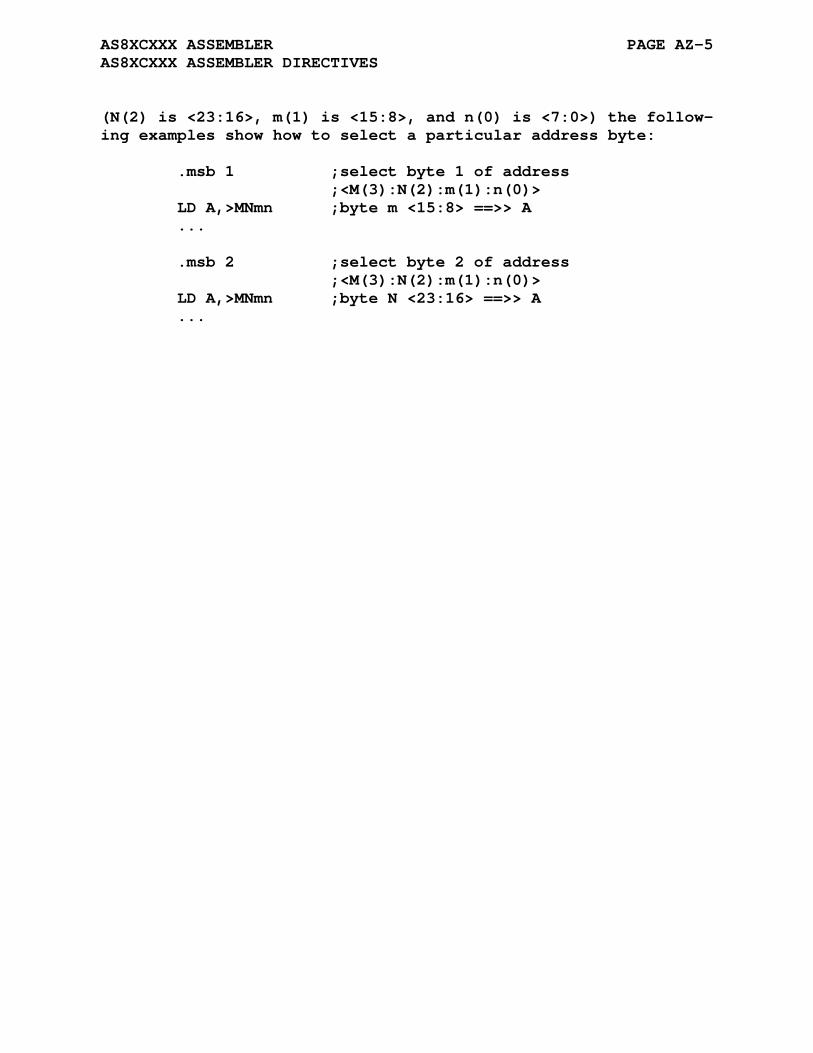
AS8XCXXX ASSEMBLER PAGE AZ-5 AS8XCXXX ASSEMBLER DIRECTIVES
(N(2) is <23:16>, m(1) is <15:8>, and n(0) is <7:0>) the follow- ing examples show how to select a particular address byte:
.msb 1 ;select byte 1 of address ;<M(3):N(2):m(1):n(0)> LD A,>MNmn ;byte m <15:8> ==>> A ... .msb 2 ;select byte 2 of address ;<M(3):N(2):m(1):n(0)> LD A,>MNmn ;byte N <23:16> ==>> A ...

AS8XCXXX ASSEMBLER PAGE AZ-6 AS8XCXXX ASSEMBLER DIRECTIVES
AZ.3 DS8XCXXX REGISTER SET
The AS8XCXXX cross assembler supports the Dallas Semiconductor DS8XCXXX series of 8051-compatible devices. These microproces- sors retain instruction set and object code compatability with the 8051 microprocessor. The DS8XCXXX family is updated with several new peripherals while providing all the standard features of the 80C32 microprocessor.
The following is a list of the registers used by AS8XCXXX:
a,b - 8-bit accumulators r0,r1,r2,r3 - 8-bit registers r4,r5,r6,r7 dptr - data pointer sp - stack pointer pc - program counter psw - status word c - carry (bit in status word)
AZ.4 DS8XCXXX INSTRUCTION SET
The following tables list all DS8XCXXX mnemonics recognized by the AS8XCXXX assembler. The following list specifies the format for each addressing mode supported by AS8XCXXX:
#data immediate data byte or word data r,r1,r2 register r0,r1,r2,r3,r4,r5,r6, or r7 @r indirect on register r0 or r1 @dptr indirect on data pointer @a+dptr indirect on accumulator plus data pointer @a+pc indirect on accumulator plus program counter addr direct memory address bitaddr bit address label call or jump label
The terms data, addr, bitaddr, and label may all be expressions.
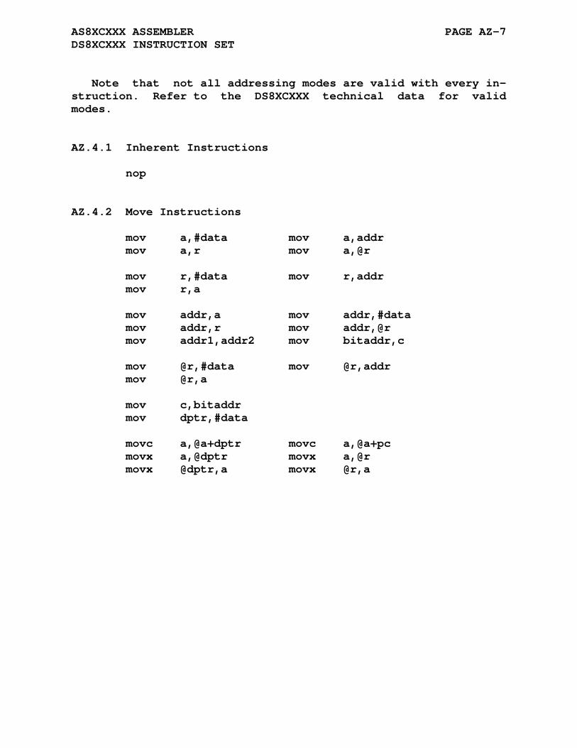
AS8XCXXX ASSEMBLER PAGE AZ-7 DS8XCXXX INSTRUCTION SET
Note that not all addressing modes are valid with every in- struction. Refer to the DS8XCXXX technical data for valid modes.
AZ.4.1 Inherent Instructions
nop
AZ.4.2 Move Instructions
mov a,#data mov a,addr mov a,r mov a,@r mov r,#data mov r,addr mov r,a mov addr,a mov addr,#data mov addr,r mov addr,@r mov addr1,addr2 mov bitaddr,c mov @r,#data mov @r,addr mov @r,a mov c,bitaddr mov dptr,#data movc a,@a+dptr movc a,@a+pc movx a,@dptr movx a,@r movx @dptr,a movx @r,a
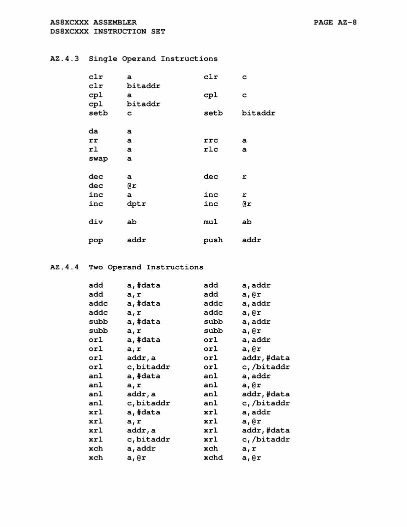
AS8XCXXX ASSEMBLER PAGE AZ-8 DS8XCXXX INSTRUCTION SET
AZ.4.3 Single Operand Instructions
clr a clr c clr bitaddr cpl a cpl c cpl bitaddr setb c setb bitaddr da a rr a rrc a rl a rlc a swap a dec a dec r dec @r inc a inc r inc dptr inc @r div ab mul ab pop addr push addr
AZ.4.4 Two Operand Instructions
add a,#data add a,addr add a,r add a,@r addc a,#data addc a,addr addc a,r addc a,@r subb a,#data subb a,addr subb a,r subb a,@r orl a,#data orl a,addr orl a,r orl a,@r orl addr,a orl addr,#data orl c,bitaddr orl c,/bitaddr anl a,#data anl a,addr anl a,r anl a,@r anl addr,a anl addr,#data anl c,bitaddr anl c,/bitaddr xrl a,#data xrl a,addr xrl a,r xrl a,@r xrl addr,a xrl addr,#data xrl c,bitaddr xrl c,/bitaddr xch a,addr xch a,r xch a,@r xchd a,@r
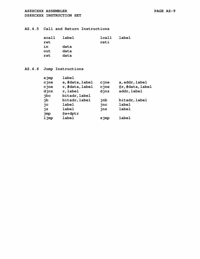
AS8XCXXX ASSEMBLER PAGE AZ-9 DS8XCXXX INSTRUCTION SET
AZ.4.5 Call and Return Instructions
acall label lcall label ret reti in data out data rst data
AZ.4.6 Jump Instructions
ajmp label cjne a,#data,label cjne a,addr,label cjne r,#data,label cjne @r,#data,label djnz r,label djnz addr,label jbc bitadr,label jb bitadr,label jnb bitadr,label jc label jnc label jz label jnz label jmp @a+dptr ljmp label sjmp label
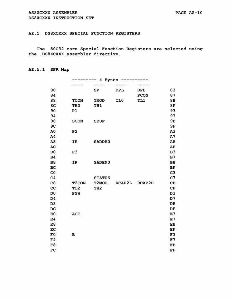
AS8XCXXX ASSEMBLER PAGE AZ-10 DS8XCXXX INSTRUCTION SET
AZ.5 DS8XCXXX SPECIAL FUNCTION REGISTERS
The 80C32 core Special Function Registers are selected using the .DS8XCXXX assembler directive.
AZ.5.1 SFR Map
--------- 4 Bytes ---------- ---- ---- ---- ---- 80 SP DPL DPH 83 84 PCON 87 88 TCON TMOD TL0 TL1 8B 8C TH0 TH1 8F 90 P1 93 94 97 98 SCON SBUF 9B 9C 9F A0 P2 A3 A4 A7 A8 IE SADDR0 AB AC AF B0 P3 B3 B4 B7 B8 IP SADEN0 BB BC BF C0 C3 C4 STATUS C7 C8 T2CON T2MOD RCAP2L RCAP2H CB CC TL2 TH2 CF D0 PSW D3 D4 D7 D8 DB DC DF E0 ACC E3 E4 E7 E8 EB EC EF F0 B F3 F4 F7 F8 FB FC FF

AS8XCXXX ASSEMBLER PAGE AZ-11 DS8XCXXX SPECIAL FUNCTION REGISTERS
AZ.5.2 Bit Addressable Registers: Generic
---------- 4 BITS ---------- ---- ---- ---- ---- 80 83 84 87 TCON 88 TCON.0 TCON.1 TCON.2 TCON.3 8B 8C TCON.4 TCON.5 TCON.6 TCON.7 8F P1 90 P1.0 P1.1 P1.2 P1.3 93 94 P1.4 P1.5 P1.6 P1.7 97 SCON 98 SCON.0 SCON.1 SCON.2 SCON.3 9B 9C SCON.4 SCON.5 SCON.6 SCON.7 9F P2 A0 P2.0 P2.1 P2.2 P2.3 A3 A4 P2.4 P2.5 P2.6 P2.7 A7 IE A8 IE.0 IE.1 IE.2 IE.3 AB AC IE.4 IE.5 EI.6 IE.7 AF P3 B0 P3.0 P3.1 P3.2 P3.3 B3 B4 P3.4 P3.5 P3.6 P3.7 B7 IP B8 IP.0 IP.1 IP.2 IP.3 BB BC IP.4 IP.5 IP.6 IP.7 BF C0 C3 C4 C7 T2CON C8 T2CON.0 T2CON.1 T2CON.2 T2CON.3 CB CC T2CON.4 T2CON.5 T2CON.6 T2CON.7 CF PSW D0 PSW.0 PSW.1 PSW.2 PSW.3 D3 D4 PSW.4 PSW.5 PSW.6 PSW.7 D7 D8 DB DC DF ACC E0 ACC.0 ACC.1 ACC.2 ACC.3 E3 E4 ACC.4 ACC.5 ACC.6 ACC.7 E7 E8 EB EC EF B F0 B.0 B.1 B.2 B.3 F3 F4 B.4 B.5 B.6 B.7 F7 F8 FB FC FF

AS8XCXXX ASSEMBLER PAGE AZ-12 DS8XCXXX SPECIAL FUNCTION REGISTERS
AZ.5.3 Bit Addressable Registers: Specific
---------- 4 BITS ---------- ---- ---- ---- ---- 80 83 84 87 TCON 88 IT0 IE0 IT1 IE1 8B 8C TR0 TF0 TR1 TF1 8F 90 93 94 97 SCON 98 RI TI RB8 TB8 9B 9C REN SM2 SM1 SMO 9F A0 A3 A4 A7 IE A8 EX0 ET0 EX1 ET1 AB AC ES0 ET2 EA AF B0 B3 B4 B7 IP B8 PX0 PT0 PX1 PT1 BB BC PS0 PT2 BF C0 C3 C4 C7 T2CON C8 CPRL2 CT2 TR2 EXEN2 CB CC TCLK RCLK EXF2 TF2 CF PSW D0 P FL OV RS0 D3 D4 RS1 F0 AC CY D7 D8 DB DC DF E0 E3 E4 E7 E8 EB EC EF F0 F3 F4 F7 F8 FB FC FF Alternates: SCON 98 9B 9C FE 9F T2CON C8 CP_RL2 C_T2 CB CC CF

AS8XCXXX ASSEMBLER PAGE AZ-13 DS8XCXXX SPECIAL FUNCTION REGISTERS
AZ.5.4 Optional Symbols: Control Bits
---------- 4 BITS ---------- ---- ---- ---- ---- 0x80 0x40 0x20 0x10 0x08 0x04 0x02 0x10 ---- ---- ---- ---- PCON 0x80 SMOD SMOD0 0x10 0x08 GF1 GF0 STOP IDLE 0x01 TMOD 0x80 T1GATE T1C_T T1M1 T1M0 0x10 0x08 T0GATE T0C_T T0M1 T0M0 0x01 STATUS 0x80 HIP LIP 0x10 0x08 0x01 T2MOD 0x80 0x10 0x08 T2OE DCEN 0x01
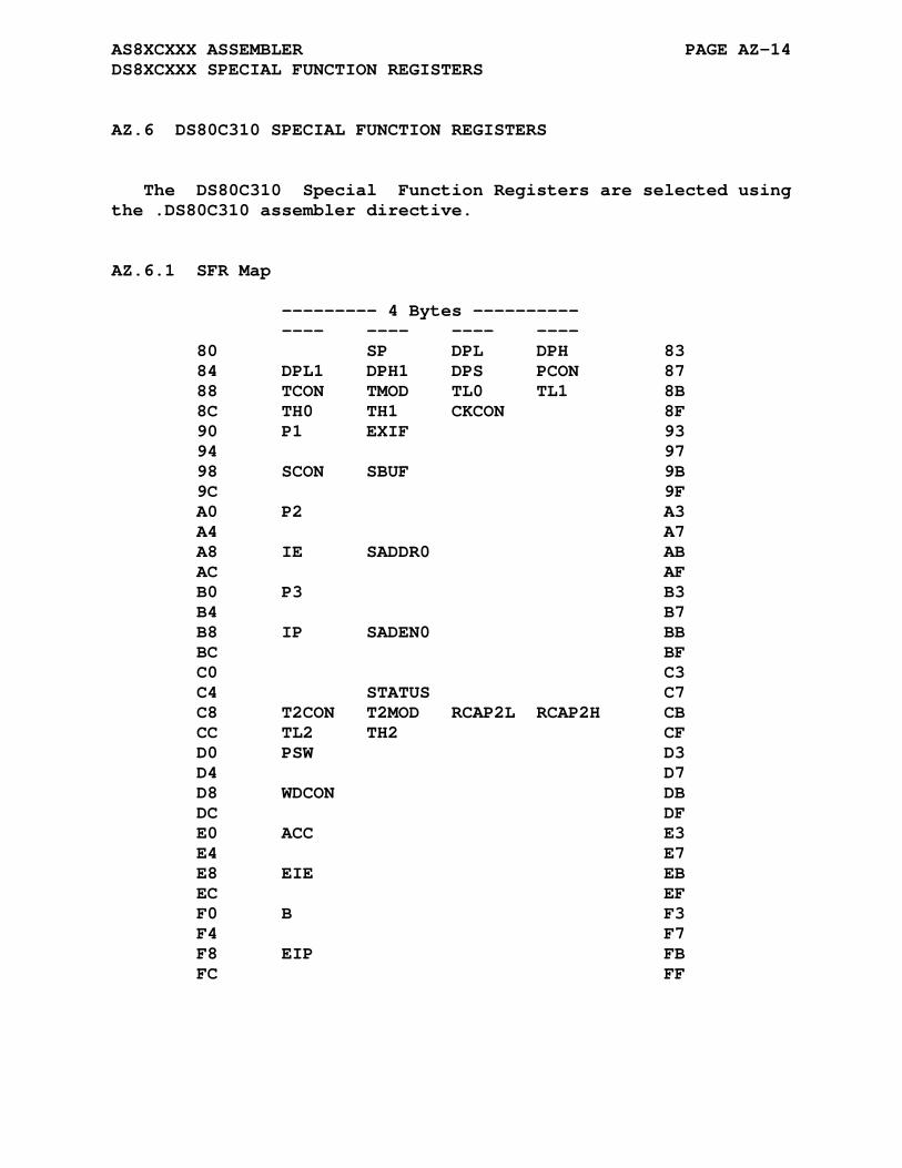
AS8XCXXX ASSEMBLER PAGE AZ-14 DS8XCXXX SPECIAL FUNCTION REGISTERS
AZ.6 DS80C310 SPECIAL FUNCTION REGISTERS
The DS80C310 Special Function Registers are selected using the .DS80C310 assembler directive.
AZ.6.1 SFR Map
--------- 4 Bytes ---------- ---- ---- ---- ---- 80 SP DPL DPH 83 84 DPL1 DPH1 DPS PCON 87 88 TCON TMOD TL0 TL1 8B 8C TH0 TH1 CKCON 8F 90 P1 EXIF 93 94 97 98 SCON SBUF 9B 9C 9F A0 P2 A3 A4 A7 A8 IE SADDR0 AB AC AF B0 P3 B3 B4 B7 B8 IP SADEN0 BB BC BF C0 C3 C4 STATUS C7 C8 T2CON T2MOD RCAP2L RCAP2H CB CC TL2 TH2 CF D0 PSW D3 D4 D7 D8 WDCON DB DC DF E0 ACC E3 E4 E7 E8 EIE EB EC EF F0 B F3 F4 F7 F8 EIP FB FC FF
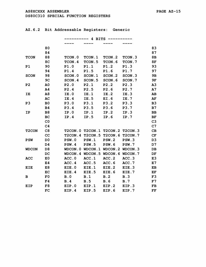
AS8XCXXX ASSEMBLER PAGE AZ-15 DS80C310 SPECIAL FUNCTION REGISTERS
AZ.6.2 Bit Addressable Registers: Generic
---------- 4 BITS ---------- ---- ---- ---- ---- 80 83 84 87 TCON 88 TCON.0 TCON.1 TCON.2 TCON.3 8B 8C TCON.4 TCON.5 TCON.6 TCON.7 8F P1 90 P1.0 P1.1 P1.2 P1.3 93 94 P1.4 P1.5 P1.6 P1.7 97 SCON 98 SCON.0 SCON.1 SCON.2 SCON.3 9B 9C SCON.4 SCON.5 SCON.6 SCON.7 9F P2 A0 P2.0 P2.1 P2.2 P2.3 A3 A4 P2.4 P2.5 P2.6 P2.7 A7 IE A8 IE.0 IE.1 IE.2 IE.3 AB AC IE.4 IE.5 EI.6 IE.7 AF P3 B0 P3.0 P3.1 P3.2 P3.3 B3 B4 P3.4 P3.5 P3.6 P3.7 B7 IP B8 IP.0 IP.1 IP.2 IP.3 BB BC IP.4 IP.5 IP.6 IP.7 BF C0 C3 C4 C7 T2CON C8 T2CON.0 T2CON.1 T2CON.2 T2CON.3 CB CC T2CON.4 T2CON.5 T2CON.6 T2CON.7 CF PSW D0 PSW.0 PSW.1 PSW.2 PSW.3 D3 D4 PSW.4 PSW.5 PSW.6 PSW.7 D7 WDCON D8 WDCON.0 WDCON.1 WDCON.2 WDCON.3 DB DC WDCON.4 WDCON.5 WDCON.6 WDCON.7 DF ACC E0 ACC.0 ACC.1 ACC.2 ACC.3 E3 E4 ACC.4 ACC.5 ACC.6 ACC.7 E7 EIE E8 EIE.0 EIE.1 EIE.2 EIE.3 EB EC EIE.4 EIE.5 EIE.6 EIE.7 EF B F0 B.0 B.1 B.2 B.3 F3 F4 B.4 B.5 B.6 B.7 F7 EIP F8 EIP.0 EIP.1 EIP.2 EIP.3 FB FC EIP.4 EIP.5 EIP.6 EIP.7 FF

AS8XCXXX ASSEMBLER PAGE AZ-16 DS80C310 SPECIAL FUNCTION REGISTERS
AZ.6.3 Bit Addressable Registers: Specific
---------- 4 BITS ---------- ---- ---- ---- ---- 80 83 84 87 TCON 88 IT0 IE0 IT1 IE1 8B 8C TR0 TF0 TR1 TF1 8F 90 93 94 97 SCON 98 RI TI RB8 TB8 9B 9C REN SM2 SM1 SMO 9F A0 A3 A4 A7 IE A8 EX0 ET0 EX1 ET1 AB AC ES0 ET2 EA AF B0 B3 B4 B7 IP B8 PX0 PT0 PX1 PT1 BB BC PS0 PT2 BF C0 C3 C4 C7 T2CON C8 CPRL2 CT2 TR2 EXEN2 CB CC TCLK RCLK EXF2 TF2 CF PSW D0 P FL OV RS0 D3 D4 RS1 F0 AC CY D7 WDCON D8 DB DC POR DF E0 E3 E4 E7 EIE E8 EX2 EX3 EX4 EX5 EB EC EF F0 F3 F4 F7 EIP F8 PX2 PX3 PX4 PX5 FB FC FF Alternates: SCON 98 9B 9C FE 9F T2CON C8 CP_RL2 C_T2 CB CC CF
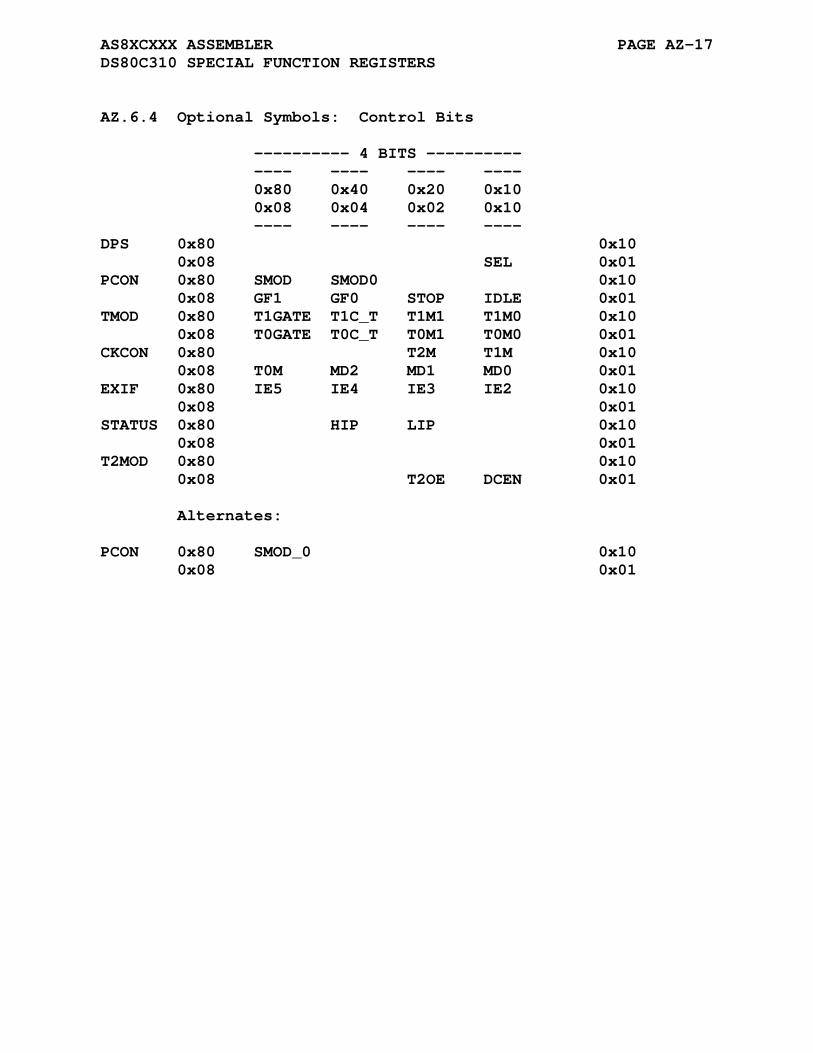
AS8XCXXX ASSEMBLER PAGE AZ-17 DS80C310 SPECIAL FUNCTION REGISTERS
AZ.6.4 Optional Symbols: Control Bits
---------- 4 BITS ---------- ---- ---- ---- ---- 0x80 0x40 0x20 0x10 0x08 0x04 0x02 0x10 ---- ---- ---- ---- DPS 0x80 0x10 0x08 SEL 0x01 PCON 0x80 SMOD SMOD0 0x10 0x08 GF1 GF0 STOP IDLE 0x01 TMOD 0x80 T1GATE T1C_T T1M1 T1M0 0x10 0x08 T0GATE T0C_T T0M1 T0M0 0x01 CKCON 0x80 T2M T1M 0x10 0x08 T0M MD2 MD1 MD0 0x01 EXIF 0x80 IE5 IE4 IE3 IE2 0x10 0x08 0x01 STATUS 0x80 HIP LIP 0x10 0x08 0x01 T2MOD 0x80 0x10 0x08 T2OE DCEN 0x01 Alternates: PCON 0x80 SMOD_0 0x10 0x08 0x01
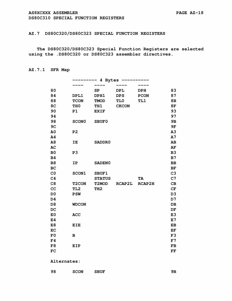
AS8XCXXX ASSEMBLER PAGE AZ-18 DS80C310 SPECIAL FUNCTION REGISTERS
AZ.7 DS80C320/DS80C323 SPECIAL FUNCTION REGISTERS
The DS80C320/DS80C323 Special Function Registers are selected using the .DS80C320 or DS80C323 assembler directives.
AZ.7.1 SFR Map
--------- 4 Bytes ---------- ---- ---- ---- ---- 80 SP DPL DPH 83 84 DPL1 DPH1 DPS PCON 87 88 TCON TMOD TL0 TL1 8B 8C TH0 TH1 CKCON 8F 90 P1 EXIF 93 94 97 98 SCON0 SBUF0 9B 9C 9F A0 P2 A3 A4 A7 A8 IE SADDR0 AB AC AF B0 P3 B3 B4 B7 B8 IP SADEN0 BB BC BF C0 SCON1 SBUF1 C3 C4 STATUS TA C7 C8 T2CON T2MOD RCAP2L RCAP2H CB CC TL2 TH2 CF D0 PSW D3 D4 D7 D8 WDCON DB DC DF E0 ACC E3 E4 E7 E8 EIE EB EC EF F0 B F3 F4 F7 F8 EIP FB FC FF Alternates: 98 SCON SBUF 9B

AS8XCXXX ASSEMBLER PAGE AZ-19 DS80C320/DS80C323 SPECIAL FUNCTION REGISTERS
AZ.7.2 Bit Addressable Registers: Generic
---------- 4 BITS ---------- ---- ---- ---- ---- 80 83 84 87 TCON 88 TCON.0 TCON.1 TCON.2 TCON.3 8B 8C TCON.4 TCON.5 TCON.6 TCON.7 8F P1 90 P1.0 P1.1 P1.2 P1.3 93 94 P1.4 P1.5 P1.6 P1.7 97 SCON0 98 SCON0.0 SCON0.1 SCON0.2 SCON0.3 9B 9C SCON0.4 SCON0.5 SCON0.6 SCON0.7 9F P2 A0 P2.0 P2.1 P2.2 P2.3 A3 A4 P2.4 P2.5 P2.6 P2.7 A7 IE A8 IE.0 IE.1 IE.2 IE.3 AB AC IE.4 IE.5 EI.6 IE.7 AF P3 B0 P3.0 P3.1 P3.2 P3.3 B3 B4 P3.4 P3.5 P3.6 P3.7 B7 IP B8 IP.0 IP.1 IP.2 IP.3 BB BC IP.4 IP.5 IP.6 IP.7 BF SCON1 C0 SCON1.0 SCON1.1 SCON1.2 SCON1.3 C3 C4 SCON1.4 SCON1.5 SCON1.6 SCON1.7 C7 T2CON C8 T2CON.0 T2CON.1 T2CON.2 T2CON.3 CB CC T2CON.4 T2CON.5 T2CON.6 T2CON.7 CF PSW D0 PSW.0 PSW.1 PSW.2 PSW.3 D3 D4 PSW.4 PSW.5 PSW.6 PSW.7 D7 WDCON D8 WDCON.0 WDCON.1 WDCON.2 WDCON.3 DB DC WDCON.4 WDCON.5 WDCON.6 WDCON.7 DF ACC E0 ACC.0 ACC.1 ACC.2 ACC.3 E3 E4 ACC.4 ACC.5 ACC.6 ACC.7 E7 EIE E8 EIE.0 EIE.1 EIE.2 EIE.3 EB EC EIE.4 EIE.5 EIE.6 EIE.7 EF B F0 B.0 B.1 B.2 B.3 F3 F4 B.4 B.5 B.6 B.7 F7 EIP F8 EIP.0 EIP.1 EIP.2 EIP.3 FB FC EIP.4 EIP.5 EIP.6 EIP.7 FF Alternates: SCON 98 SCON.0 SCON.1 SCON.2 SCON.3 9B 9C SCON.4 SCON.5 SCON.6 SCON.7 9F
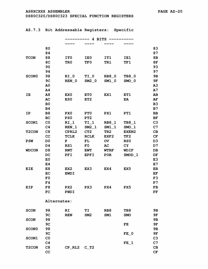
AS8XCXXX ASSEMBLER PAGE AZ-20 DS80C320/DS80C323 SPECIAL FUNCTION REGISTERS
AZ.7.3 Bit Addressable Registers: Specific
---------- 4 BITS ---------- ---- ---- ---- ---- 80 83 84 87 TCON 88 IT0 IE0 IT1 IE1 8B 8C TR0 TF0 TR1 TF1 8F 90 93 94 97 SCON0 98 RI_0 TI_0 RB8_0 TB8_0 9B 9C REN_0 SM2_0 SM1_0 SMO_0 9F A0 A3 A4 A7 IE A8 EX0 ET0 EX1 ET1 AB AC ES0 ET2 EA AF B0 B3 B4 B7 IP B8 PX0 PT0 PX1 PT1 BB BC PS0 PT2 BF SCON1 C0 RI_1 TI_1 RB8_1 TB8_1 C3 C4 REN_1 SM2_1 SM1_1 SMO_1 C7 T2CON C8 CPRL2 CT2 TR2 EXEN2 CB CC TCLK RCLK EXF2 TF2 CF PSW D0 P FL OV RS0 D3 D4 RS1 F0 AC CY D7 WDCON D8 RWT EWT WTRF WDIF DB DC PFI EPFI POR SMOD_1 DF E0 E3 E4 E7 EIE E8 EX2 EX3 EX4 EX5 EB EC EWDI EF F0 F3 F4 F7 EIP F8 PX2 PX3 PX4 PX5 FB FC PWDI FF Alternates: SCON 98 RI TI RB8 TB8 9B 9C REN SM2 SM1 SMO 9F SCON 98 9B 9C FE 9F SCON0 98 9B 9C FE_0 9F SCON1 C0 C3 C4 FE_1 C7 T2CON C8 CP_RL2 C_T2 CB CC CF
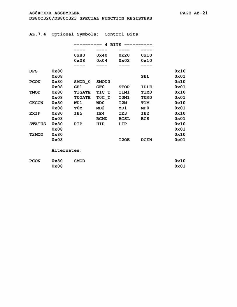
AS8XCXXX ASSEMBLER PAGE AZ-21 DS80C320/DS80C323 SPECIAL FUNCTION REGISTERS
AZ.7.4 Optional Symbols: Control Bits
---------- 4 BITS ---------- ---- ---- ---- ---- 0x80 0x40 0x20 0x10 0x08 0x04 0x02 0x10 ---- ---- ---- ---- DPS 0x80 0x10 0x08 SEL 0x01 PCON 0x80 SMOD_0 SMOD0 0x10 0x08 GF1 GF0 STOP IDLE 0x01 TMOD 0x80 T1GATE T1C_T T1M1 T1M0 0x10 0x08 T0GATE T0C_T T0M1 T0M0 0x01 CKCON 0x80 WD1 WD0 T2M T1M 0x10 0x08 T0M MD2 MD1 MD0 0x01 EXIF 0x80 IE5 IE4 IE3 IE2 0x10 0x08 RGMD RGSL BGS 0x01 STATUS 0x80 PIP HIP LIP 0x10 0x08 0x01 T2MOD 0x80 0x10 0x08 T2OE DCEN 0x01 Alternates: PCON 0x80 SMOD 0x10 0x08 0x01
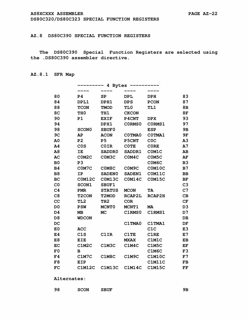
AS8XCXXX ASSEMBLER PAGE AZ-22 DS80C320/DS80C323 SPECIAL FUNCTION REGISTERS
AZ.8 DS80C390 SPECIAL FUNCTION REGISTERS
The DS80C390 Special Function Registers are selected using the .DS80C390 assembler directive.
AZ.8.1 SFR Map
--------- 4 Bytes ---------- ---- ---- ---- ---- 80 P4 SP DPL DPH 83 84 DPL1 DPH1 DPS PCON 87 88 TCON TMOD TL0 TL1 8B 8C TH0 TH1 CKCON 8F 90 P1 EXIF P4CNT DPX 93 94 DPX1 C0RMS0 C0RMS1 97 98 SCON0 SBUF0 ESP 9B 9C AP ACON C0TMA0 C0TMA1 9F A0 P2 P5 P5CNT C0C A3 A4 C0S C0IR C0TE C0RE A7 A8 IE SADDR0 SADDR1 C0M1C AB AC C0M2C C0M3C C0M4C C0M5C AF B0 P3 C0M6C B3 B4 C0M7C C0M8C C0M9C C0M10C B7 B8 IP SADEN0 SADEN1 C0M11C BB BC C0M12C C0M13C C0M14C C0M15C BF C0 SCON1 SBUF1 C3 C4 PMR STATUS MCON TA C7 C8 T2CON T2MOD RCAP2L RCAP2H CB CC TL2 TH2 COR CF D0 PSW MCNT0 MCNT1 MA D3 D4 MB MC C1RMS0 C1RMS1 D7 D8 WDCON DB DC C1TMA0 C1TMA1 DF E0 ACC C1C E3 E4 C1S C1IR C1TE C1RE E7 E8 EIE MXAX C1M1C EB EC C1M2C C1M3C C1M4C C1M5C EF F0 B C1M6C F3 F4 C1M7C C1M8C C1M9C C1M10C F7 F8 EIP C1M11C FB FC C1M12C C1M13C C1M14C C1M15C FF Alternates: 98 SCON SBUF 9B
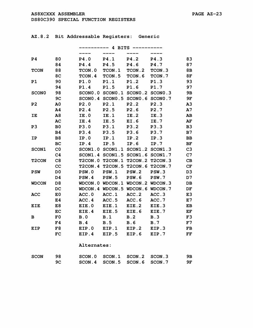
AS8XCXXX ASSEMBLER PAGE AZ-23 DS80C390 SPECIAL FUNCTION REGISTERS
AZ.8.2 Bit Addressable Registers: Generic
---------- 4 BITS ---------- ---- ---- ---- ---- P4 80 P4.0 P4.1 P4.2 P4.3 83 84 P4.4 P4.5 P4.6 P4.7 87 TCON 88 TCON.0 TCON.1 TCON.2 TCON.3 8B 8C TCON.4 TCON.5 TCON.6 TCON.7 8F P1 90 P1.0 P1.1 P1.2 P1.3 93 94 P1.4 P1.5 P1.6 P1.7 97 SCON0 98 SCON0.0 SCON0.1 SCON0.2 SCON0.3 9B 9C SCON0.4 SCON0.5 SCON0.6 SCON0.7 9F P2 A0 P2.0 P2.1 P2.2 P2.3 A3 A4 P2.4 P2.5 P2.6 P2.7 A7 IE A8 IE.0 IE.1 IE.2 IE.3 AB AC IE.4 IE.5 EI.6 IE.7 AF P3 B0 P3.0 P3.1 P3.2 P3.3 B3 B4 P3.4 P3.5 P3.6 P3.7 B7 IP B8 IP.0 IP.1 IP.2 IP.3 BB BC IP.4 IP.5 IP.6 IP.7 BF SCON1 C0 SCON1.0 SCON1.1 SCON1.2 SCON1.3 C3 C4 SCON1.4 SCON1.5 SCON1.6 SCON1.7 C7 T2CON C8 T2CON.0 T2CON.1 T2CON.2 T2CON.3 CB CC T2CON.4 T2CON.5 T2CON.6 T2CON.7 CF PSW D0 PSW.0 PSW.1 PSW.2 PSW.3 D3 D4 PSW.4 PSW.5 PSW.6 PSW.7 D7 WDCON D8 WDCON.0 WDCON.1 WDCON.2 WDCON.3 DB DC WDCON.4 WDCON.5 WDCON.6 WDCON.7 DF ACC E0 ACC.0 ACC.1 ACC.2 ACC.3 E3 E4 ACC.4 ACC.5 ACC.6 ACC.7 E7 EIE E8 EIE.0 EIE.1 EIE.2 EIE.3 EB EC EIE.4 EIE.5 EIE.6 EIE.7 EF B F0 B.0 B.1 B.2 B.3 F3 F4 B.4 B.5 B.6 B.7 F7 EIP F8 EIP.0 EIP.1 EIP.2 EIP.3 FB FC EIP.4 EIP.5 EIP.6 EIP.7 FF Alternates: SCON 98 SCON.0 SCON.1 SCON.2 SCON.3 9B 9C SCON.4 SCON.5 SCON.6 SCON.7 9F
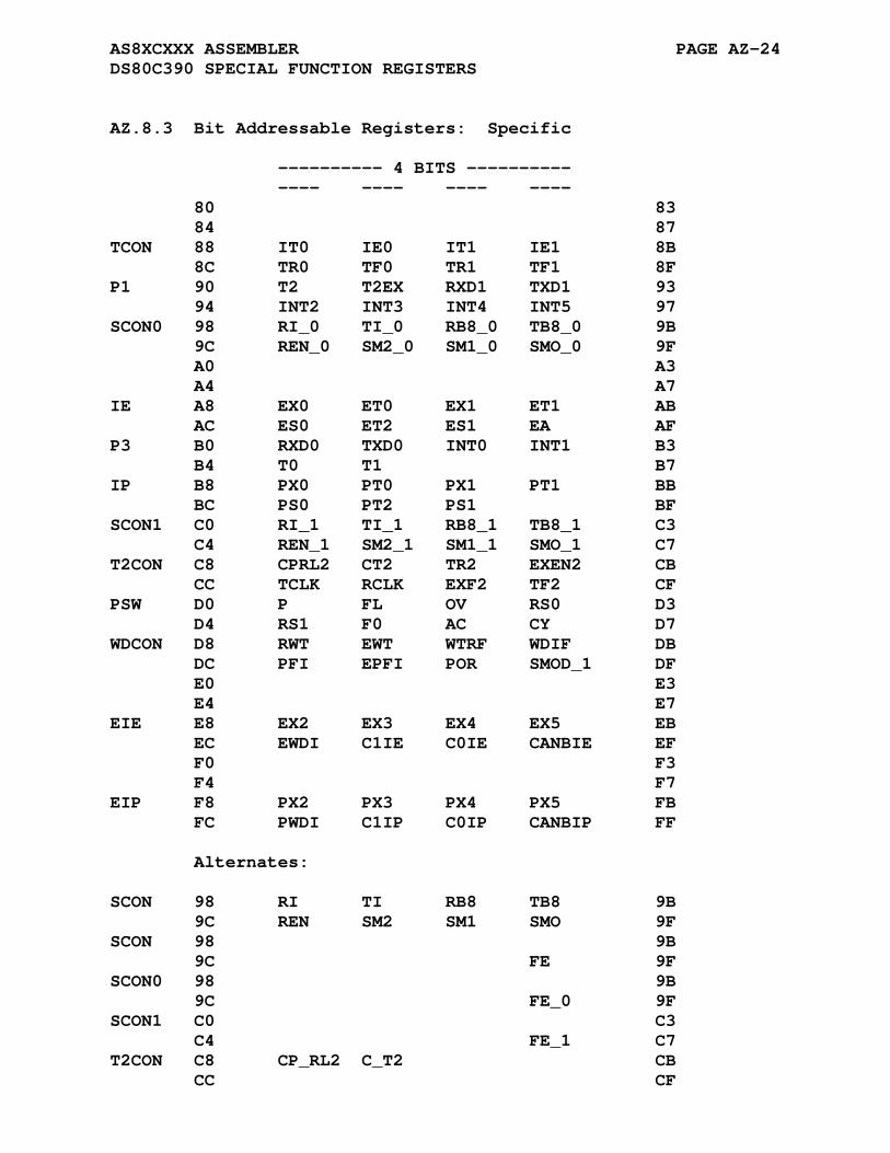
AS8XCXXX ASSEMBLER PAGE AZ-24 DS80C390 SPECIAL FUNCTION REGISTERS
AZ.8.3 Bit Addressable Registers: Specific
---------- 4 BITS ---------- ---- ---- ---- ---- 80 83 84 87 TCON 88 IT0 IE0 IT1 IE1 8B 8C TR0 TF0 TR1 TF1 8F P1 90 T2 T2EX RXD1 TXD1 93 94 INT2 INT3 INT4 INT5 97 SCON0 98 RI_0 TI_0 RB8_0 TB8_0 9B 9C REN_0 SM2_0 SM1_0 SMO_0 9F A0 A3 A4 A7 IE A8 EX0 ET0 EX1 ET1 AB AC ES0 ET2 ES1 EA AF P3 B0 RXD0 TXD0 INT0 INT1 B3 B4 T0 T1 B7 IP B8 PX0 PT0 PX1 PT1 BB BC PS0 PT2 PS1 BF SCON1 C0 RI_1 TI_1 RB8_1 TB8_1 C3 C4 REN_1 SM2_1 SM1_1 SMO_1 C7 T2CON C8 CPRL2 CT2 TR2 EXEN2 CB CC TCLK RCLK EXF2 TF2 CF PSW D0 P FL OV RS0 D3 D4 RS1 F0 AC CY D7 WDCON D8 RWT EWT WTRF WDIF DB DC PFI EPFI POR SMOD_1 DF E0 E3 E4 E7 EIE E8 EX2 EX3 EX4 EX5 EB EC EWDI C1IE C0IE CANBIE EF F0 F3 F4 F7 EIP F8 PX2 PX3 PX4 PX5 FB FC PWDI C1IP C0IP CANBIP FF Alternates: SCON 98 RI TI RB8 TB8 9B 9C REN SM2 SM1 SMO 9F SCON 98 9B 9C FE 9F SCON0 98 9B 9C FE_0 9F SCON1 C0 C3 C4 FE_1 C7 T2CON C8 CP_RL2 C_T2 CB CC CF
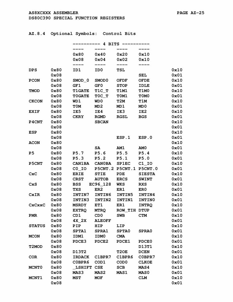
AS8XCXXX ASSEMBLER PAGE AZ-25 DS80C390 SPECIAL FUNCTION REGISTERS
AZ.8.4 Optional Symbols: Control Bits
---------- 4 BITS ---------- ---- ---- ---- ---- 0x80 0x40 0x20 0x10 0x08 0x04 0x02 0x10 ---- ---- ---- ---- DPS 0x80 ID1 ID0 TSL 0x10 0x08 SEL 0x01 PCON 0x80 SMOD_0 SMOD0 OFDF OFDE 0x10 0x08 GF1 GF0 STOP IDLE 0x01 TMOD 0x80 T1GATE T1C_T T1M1 T1M0 0x10 0x08 T0GATE T0C_T T0M1 T0M0 0x01 CKCON 0x80 WD1 WD0 T2M T1M 0x10 0x08 T0M MD2 MD1 MD0 0x01 EXIF 0x80 IE5 IE4 IE3 IE2 0x10 0x08 CKRY RGMD RGSL BGS 0x01 P4CNT 0x80 SBCAN 0x10 0x08 0x01 ESP 0x80 0x10 0x08 ESP.1 ESP.0 0x01 ACON 0x80 0x10 0x08 SA AM1 AM0 0x01 P5 0x80 P5.7 P5.6 P5.5 P5.4 0x10 0x08 P5.3 P5.2 P5.1 P5.0 0x01 P5CNT 0x80 CAN1BA CAN0BA SP1EC C1_IO 0x10 0x08 C0_IO P5CNT.2 P5CNT.1 P5CNT.0 0x01 CxC 0x80 ERIE STIE PDE SIESTA 0x10 0x08 CRST AUTOB ERCS SWINT 0x01 CxS 0x80 BSS EC96_128 WKS RXS 0x10 0x08 TXS ER2 ER1 ER0 0x01 CxIR 0x80 INTIN7 INTIN6 INTIN5 INTIN4 0x10 0x08 INTIN3 INTIN2 INTIN1 INTIN0 0x01 CxCxxC 0x80 MSRDY ET1 ER1 INTRQ 0x10 0x08 EXTRQ MTRQ ROW_TIH DTUP 0x01 PMR 0x80 CD1 CD0 SWB CTM 0x10 0x08 4X_2X ALEOFF 0x01 STATUS 0x80 PIP HIP LIP 0x10 0x08 SPTA1 SPRA1 SPTA0 SPRA0 0x01 MCON 0x80 IDM1 IDM0 CMA 0x10 0x08 PDCE3 PDCE2 PDCE1 PDCE0 0x01 T2MOD 0x80 D13T1 0x10 0x08 D13T2 T2OE DCEN 0x01 COR 0x80 IRDACK C1BPR7 C1BPR6 C0BPR7 0x10 0x08 C0BPR6 COD1 COD0 CLKOE 0x01 MCNT0 0x80 _LSHIFT CSE SCB MAS4 0x10 0x08 MAS3 MAS2 MAS1 MAS0 0x01 MCNT1 0x80 MST MOF CLM 0x10 0x08 0x01
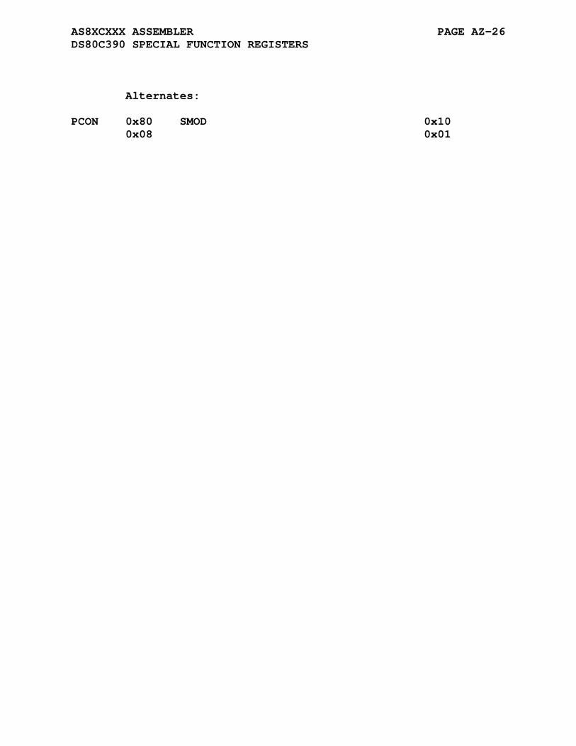
AS8XCXXX ASSEMBLER PAGE AZ-26 DS80C390 SPECIAL FUNCTION REGISTERS
Alternates: PCON 0x80 SMOD 0x10 0x08 0x01
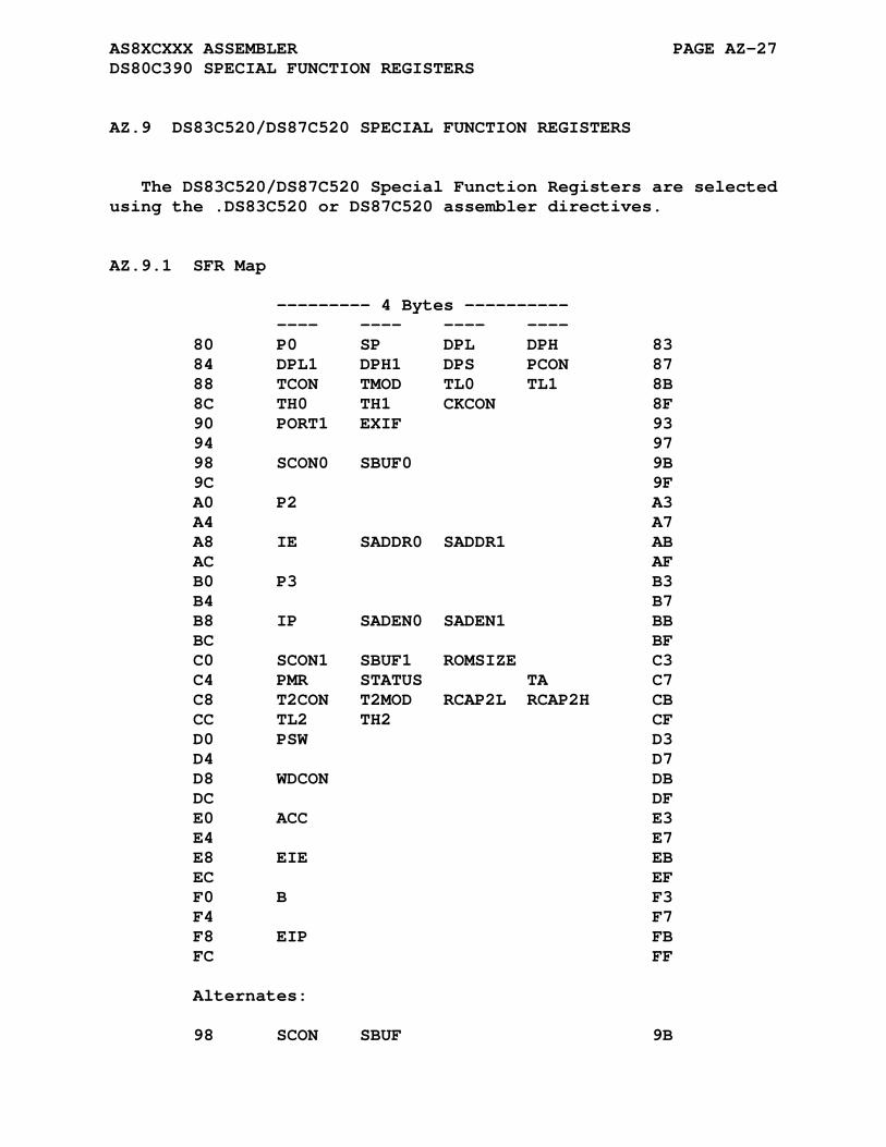
AS8XCXXX ASSEMBLER PAGE AZ-27 DS80C390 SPECIAL FUNCTION REGISTERS
AZ.9 DS83C520/DS87C520 SPECIAL FUNCTION REGISTERS
The DS83C520/DS87C520 Special Function Registers are selected using the .DS83C520 or DS87C520 assembler directives.
AZ.9.1 SFR Map
--------- 4 Bytes ---------- ---- ---- ---- ---- 80 P0 SP DPL DPH 83 84 DPL1 DPH1 DPS PCON 87 88 TCON TMOD TL0 TL1 8B 8C TH0 TH1 CKCON 8F 90 PORT1 EXIF 93 94 97 98 SCON0 SBUF0 9B 9C 9F A0 P2 A3 A4 A7 A8 IE SADDR0 SADDR1 AB AC AF B0 P3 B3 B4 B7 B8 IP SADEN0 SADEN1 BB BC BF C0 SCON1 SBUF1 ROMSIZE C3 C4 PMR STATUS TA C7 C8 T2CON T2MOD RCAP2L RCAP2H CB CC TL2 TH2 CF D0 PSW D3 D4 D7 D8 WDCON DB DC DF E0 ACC E3 E4 E7 E8 EIE EB EC EF F0 B F3 F4 F7 F8 EIP FB FC FF Alternates: 98 SCON SBUF 9B
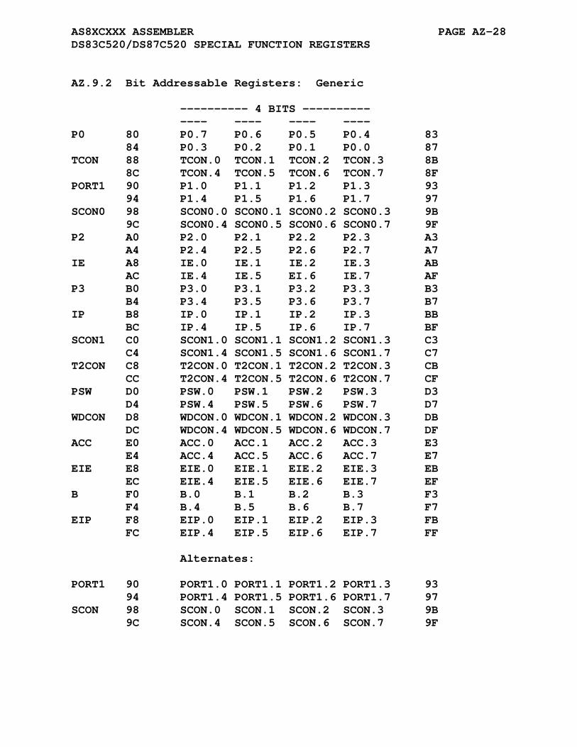
AS8XCXXX ASSEMBLER PAGE AZ-28 DS83C520/DS87C520 SPECIAL FUNCTION REGISTERS
AZ.9.2 Bit Addressable Registers: Generic
---------- 4 BITS ---------- ---- ---- ---- ---- P0 80 P0.7 P0.6 P0.5 P0.4 83 84 P0.3 P0.2 P0.1 P0.0 87 TCON 88 TCON.0 TCON.1 TCON.2 TCON.3 8B 8C TCON.4 TCON.5 TCON.6 TCON.7 8F PORT1 90 P1.0 P1.1 P1.2 P1.3 93 94 P1.4 P1.5 P1.6 P1.7 97 SCON0 98 SCON0.0 SCON0.1 SCON0.2 SCON0.3 9B 9C SCON0.4 SCON0.5 SCON0.6 SCON0.7 9F P2 A0 P2.0 P2.1 P2.2 P2.3 A3 A4 P2.4 P2.5 P2.6 P2.7 A7 IE A8 IE.0 IE.1 IE.2 IE.3 AB AC IE.4 IE.5 EI.6 IE.7 AF P3 B0 P3.0 P3.1 P3.2 P3.3 B3 B4 P3.4 P3.5 P3.6 P3.7 B7 IP B8 IP.0 IP.1 IP.2 IP.3 BB BC IP.4 IP.5 IP.6 IP.7 BF SCON1 C0 SCON1.0 SCON1.1 SCON1.2 SCON1.3 C3 C4 SCON1.4 SCON1.5 SCON1.6 SCON1.7 C7 T2CON C8 T2CON.0 T2CON.1 T2CON.2 T2CON.3 CB CC T2CON.4 T2CON.5 T2CON.6 T2CON.7 CF PSW D0 PSW.0 PSW.1 PSW.2 PSW.3 D3 D4 PSW.4 PSW.5 PSW.6 PSW.7 D7 WDCON D8 WDCON.0 WDCON.1 WDCON.2 WDCON.3 DB DC WDCON.4 WDCON.5 WDCON.6 WDCON.7 DF ACC E0 ACC.0 ACC.1 ACC.2 ACC.3 E3 E4 ACC.4 ACC.5 ACC.6 ACC.7 E7 EIE E8 EIE.0 EIE.1 EIE.2 EIE.3 EB EC EIE.4 EIE.5 EIE.6 EIE.7 EF B F0 B.0 B.1 B.2 B.3 F3 F4 B.4 B.5 B.6 B.7 F7 EIP F8 EIP.0 EIP.1 EIP.2 EIP.3 FB FC EIP.4 EIP.5 EIP.6 EIP.7 FF Alternates: PORT1 90 PORT1.0 PORT1.1 PORT1.2 PORT1.3 93 94 PORT1.4 PORT1.5 PORT1.6 PORT1.7 97 SCON 98 SCON.0 SCON.1 SCON.2 SCON.3 9B 9C SCON.4 SCON.5 SCON.6 SCON.7 9F

AS8XCXXX ASSEMBLER PAGE AZ-29 DS83C520/DS87C520 SPECIAL FUNCTION REGISTERS
AZ.9.3 Bit Addressable Registers: Specific
---------- 4 BITS ---------- ---- ---- ---- ---- 80 83 84 87 TCON 88 IT0 IE0 IT1 IE1 8B 8C TR0 TF0 TR1 TF1 8F 90 93 94 97 SCON0 98 RI_0 TI_0 RB8_0 TB8_0 9B 9C REN_0 SM2_0 SM1_0 SMO_0 9F A0 A3 A4 A7 IE A8 EX0 ET0 EX1 ET1 AB AC ES0 ET2 ES1 EA AF B0 B3 B4 B7 IP B8 PX0 PT0 PX1 PT1 BB BC PS0 PT2 PS1 BF SCON1 C0 RI_1 TI_1 RB8_1 TB8_1 C3 C4 REN_1 SM2_1 SM1_1 SMO_1 C7 T2CON C8 CPRL2 CT2 TR2 EXEN2 CB CC TCLK RCLK EXF2 TF2 CF PSW D0 P FL OV RS0 D3 D4 RS1 F0 AC CY D7 WDCON D8 RWT EWT WTRF WDIF DB DC PFI EPFI POR SMOD_1 DF E0 E3 E4 E7 EIE E8 EX2 EX3 EX4 EX5 EB EC EWDI EF F0 F3 F4 F7 EIP F8 PX2 PX3 PX4 PX5 FB FC PWDI FF Alternates: SCON 98 RI TI RB8 TB8 9B 9C REN SM2 SM1 SMO 9F SCON 98 9B 9C FE 9F SCON0 98 9B 9C FE_0 9F SCON1 C0 C3 C4 FE_1 C7 T2CON C8 CP_RL2 C_T2 CB CC CF

AS8XCXXX ASSEMBLER PAGE AZ-30 DS83C520/DS87C520 SPECIAL FUNCTION REGISTERS
AZ.9.4 Optional Symbols: Control Bits
---------- 4 BITS ---------- ---- ---- ---- ---- 0x80 0x40 0x20 0x10 0x08 0x04 0x02 0x10 ---- ---- ---- ---- DPS 0x80 0x10 0x08 SEL 0x01 PCON 0x80 SMOD_0 SMOD0 0x10 0x08 GF1 GF0 STOP IDLE 0x01 TMOD 0x80 T1GATE T1C_T T1M1 T1M0 0x10 0x08 T0GATE T0C_T T0M1 T0M0 0x01 CKCON 0x80 WD1 WD0 T2M T1M 0x10 0x08 T0M MD2 MD1 MD0 0x01 EXIF 0x80 IE5 IE4 IE3 IE 0x10 0x08 XT_RG RGMD RGSL BGS 0x01 SBUF1 0x80 SB7 SB6 SB5 SB4 0x10 0x08 SB3 SB2 SB1 SB0 0x01 ROMSIZE 0x80 0x10 0x08 RMS2 RMS1 RMS0 0x01 PMR 0x80 CD1 CD0 SWB 0x10 0x08 XTOFF ALEOFF DME1 DME0 0x01 STATUS 0x80 PIP HIP LIP XTUP 0x10 0x08 SPTA1 SPRA1 SPTA0 SPRA0 0x01 T2MOD 0x80 0x10 0x08 T2OE DCEN 0x01 Alternates: PCON 0x80 SMOD 0x10 0x08 0x01
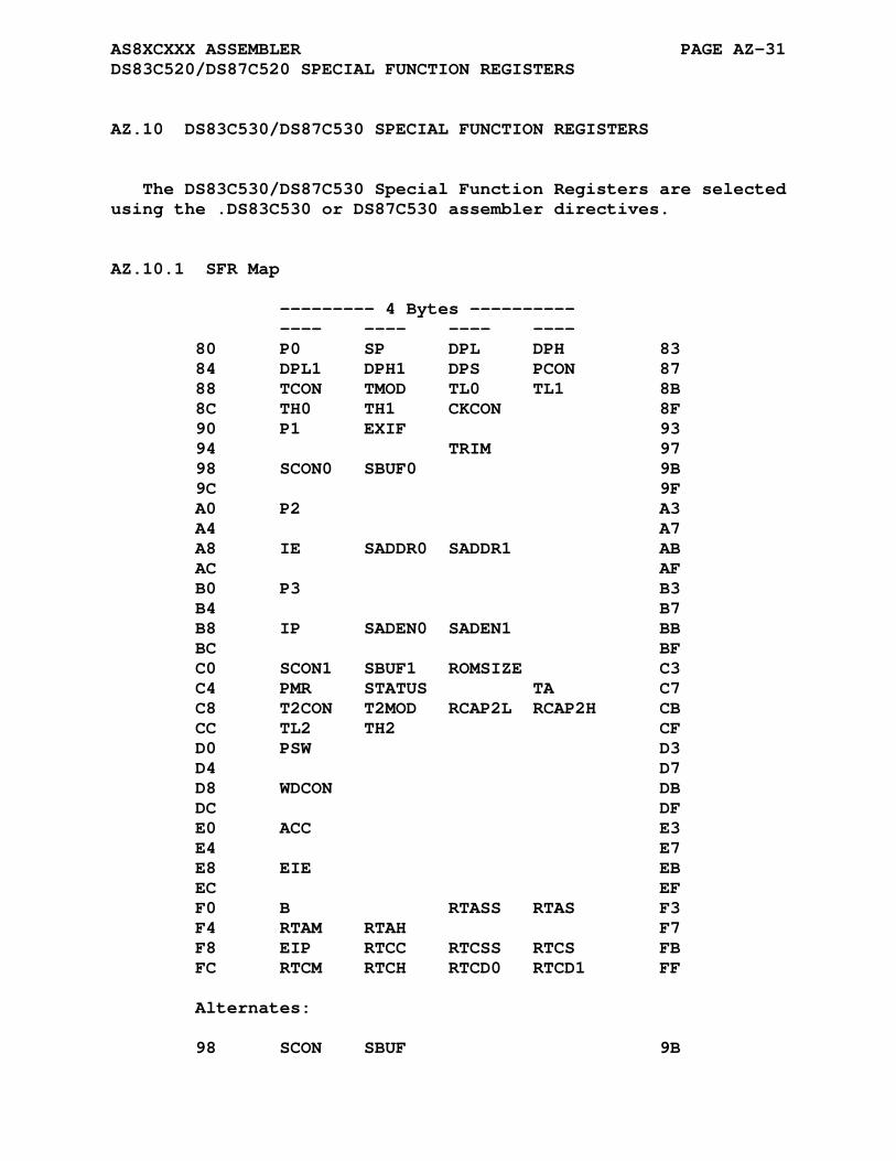
AS8XCXXX ASSEMBLER PAGE AZ-31 DS83C520/DS87C520 SPECIAL FUNCTION REGISTERS
AZ.10 DS83C530/DS87C530 SPECIAL FUNCTION REGISTERS
The DS83C530/DS87C530 Special Function Registers are selected using the .DS83C530 or DS87C530 assembler directives.
AZ.10.1 SFR Map
--------- 4 Bytes ---------- ---- ---- ---- ---- 80 P0 SP DPL DPH 83 84 DPL1 DPH1 DPS PCON 87 88 TCON TMOD TL0 TL1 8B 8C TH0 TH1 CKCON 8F 90 P1 EXIF 93 94 TRIM 97 98 SCON0 SBUF0 9B 9C 9F A0 P2 A3 A4 A7 A8 IE SADDR0 SADDR1 AB AC AF B0 P3 B3 B4 B7 B8 IP SADEN0 SADEN1 BB BC BF C0 SCON1 SBUF1 ROMSIZE C3 C4 PMR STATUS TA C7 C8 T2CON T2MOD RCAP2L RCAP2H CB CC TL2 TH2 CF D0 PSW D3 D4 D7 D8 WDCON DB DC DF E0 ACC E3 E4 E7 E8 EIE EB EC EF F0 B RTASS RTAS F3 F4 RTAM RTAH F7 F8 EIP RTCC RTCSS RTCS FB FC RTCM RTCH RTCD0 RTCD1 FF Alternates: 98 SCON SBUF 9B

AS8XCXXX ASSEMBLER PAGE AZ-32 DS83C530/DS87C530 SPECIAL FUNCTION REGISTERS
AZ.10.2 Bit Addressable Registers: Generic
---------- 4 BITS ---------- ---- ---- ---- ---- P0 80 P0.7 P0.6 P0.5 P0.4 83 84 P0.3 P0.2 P0.1 P0.0 87 TCON 88 TCON.0 TCON.1 TCON.2 TCON.3 8B 8C TCON.4 TCON.5 TCON.6 TCON.7 8F P1 90 P1.0 P1.1 P1.2 P1.3 93 94 P1.4 P1.5 P1.6 P1.7 97 SCON0 98 SCON0.0 SCON0.1 SCON0.2 SCON0.3 9B 9C SCON0.4 SCON0.5 SCON0.6 SCON0.7 9F P2 A0 P2.0 P2.1 P2.2 P2.3 A3 A4 P2.4 P2.5 P2.6 P2.7 A7 IE A8 IE.0 IE.1 IE.2 IE.3 AB AC IE.4 IE.5 EI.6 IE.7 AF P3 B0 P3.0 P3.1 P3.2 P3.3 B3 B4 P3.4 P3.5 P3.6 P3.7 B7 IP B8 IP.0 IP.1 IP.2 IP.3 BB BC IP.4 IP.5 IP.6 IP.7 BF SCON1 C0 SCON1.0 SCON1.1 SCON1.2 SCON1.3 C3 C4 SCON1.4 SCON1.5 SCON1.6 SCON1.7 C7 T2CON C8 T2CON.0 T2CON.1 T2CON.2 T2CON.3 CB CC T2CON.4 T2CON.5 T2CON.6 T2CON.7 CF PSW D0 PSW.0 PSW.1 PSW.2 PSW.3 D3 D4 PSW.4 PSW.5 PSW.6 PSW.7 D7 WDCON D8 WDCON.0 WDCON.1 WDCON.2 WDCON.3 DB DC WDCON.4 WDCON.5 WDCON.6 WDCON.7 DF ACC E0 ACC.0 ACC.1 ACC.2 ACC.3 E3 E4 ACC.4 ACC.5 ACC.6 ACC.7 E7 EIE E8 EIE.0 EIE.1 EIE.2 EIE.3 EB EC EIE.4 EIE.5 EIE.6 EIE.7 EF B F0 B.0 B.1 B.2 B.3 F3 F4 B.4 B.5 B.6 B.7 F7 EIP F8 EIP.0 EIP.1 EIP.2 EIP.3 FB FC EIP.4 EIP.5 EIP.6 EIP.7 FF Alternates: SCON 98 SCON.0 SCON.1 SCON.2 SCON.3 9B 9C SCON.4 SCON.5 SCON.6 SCON.7 9F

AS8XCXXX ASSEMBLER PAGE AZ-33 DS83C530/DS87C530 SPECIAL FUNCTION REGISTERS
AZ.10.3 Bit Addressable Registers: Specific
---------- 4 BITS ---------- ---- ---- ---- ---- 80 83 84 87 TCON 88 IT0 IE0 IT1 IE1 8B 8C TR0 TF0 TR1 TF1 8F 90 93 94 97 SCON0 98 RI_0 TI_0 RB8_0 TB8_0 9B 9C REN_0 SM2_0 SM1_0 SMO_0 9F A0 A3 A4 A7 IE A8 EX0 ET0 EX1 ET1 AB AC ES0 ET2 ES1 EA AF B0 B3 B4 B7 IP B8 PX0 PT0 PX1 PT1 BB BC PS0 PT2 PS1 BF SCON1 C0 RI_1 TI_1 RB8_1 TB8_1 C3 C4 REN_1 SM2_1 SM1_1 SMO_1 C7 T2CON C8 CPRL2 CT2 TR2 EXEN2 CB CC TCLK RCLK EXF2 TF2 CF PSW D0 P FL OV RS0 D3 D4 RS1 F0 AC CY D7 WDCON D8 RWT EWT WTRF WDIF DB DC PFI EPFI POR SMOD_1 DF E0 E3 E4 E7 EIE E8 EX2 EX3 EX4 EX5 EB EC EWDI ERTCI EF F0 F3 F4 F7 EIP F8 PX2 PX3 PX4 PX5 FB FC PWDI PRTCI FF Alternates: SCON 98 RI TI RB8 TB8 9B 9C REN SM2 SM1 SMO 9F SCON 98 9B 9C FE 9F SCON0 98 9B 9C FE_0 9F SCON1 C0 C3 C4 FE_1 C7 T2CON C8 CP_RL2 C_T2 CB CC CF

AS8XCXXX ASSEMBLER PAGE AZ-34 DS83C530/DS87C530 SPECIAL FUNCTION REGISTERS
AZ.10.4 Optional Symbols: Control Bits
---------- 4 BITS ---------- ---- ---- ---- ---- 0x80 0x40 0x20 0x10 0x08 0x04 0x02 0x10 ---- ---- ---- ---- DPS 0x80 0x10 0x08 SEL 0x01 PCON 0x80 SMOD_0 SMOD0 0x10 0x08 GF1 GF0 STOP IDLE 0x01 TMOD 0x80 T1GATE T1C_T T1M1 T1M0 0x10 0x08 T0GATE T0C_T T0M1 T0M0 0x01 CKCON 0x80 WD1 WD0 T2M T1M 0x10 0x08 T0M MD2 MD1 MD0 0x01 EXIF 0x80 IE5 IE4 IE3 IE 0x10 0x08 XT_RG RGMD RGSL BGS 0x01 TRIM 0x80 E4K X12_6 TRM2 _TRM2 0x10 0x08 TRM1 _TRM1 TRM0 _TRM0 0x01 SBUF1 0x80 SB7 SB6 SB5 SB4 0x10 0x08 SB3 SB2 SB1 SB0 0x01 ROMSIZE 0x80 0x10 0x08 RMS2 RMS1 RMS0 0x01 PMR 0x80 CD1 CD0 SWB 0x10 0x08 XTOFF ALEOFF DME1 DME0 0x01 STATUS 0x80 PIP HIP LIP XTUP 0x10 0x08 SPTA1 SPRA1 SPTA0 SPRA0 0x01 T2MOD 0x80 0x10 0x08 T2OE DCEN 0x01 RTCC 0x80 SSCE SCE MCE HCE 0x10 0x08 RTCRE RTCWE RTCIF RTCE 0x01 Alternates: PCON 0x80 SMOD 0x10 0x08 0x01

AS8XCXXX ASSEMBLER PAGE AZ-35 DS83C530/DS87C530 SPECIAL FUNCTION REGISTERS
AZ.11 DS83C550/DS87C550 SPECIAL FUNCTION REGISTERS
The DS83C550/DS87C550 Special Function Registers are selected using the .DS83C550 or DS87C550 assembler directives.
AZ.11.1 SFR Map
--------- 4 Bytes ---------- ---- ---- ---- ---- 80 PORT0 SP DPL DPH 83 84 DPL1 DPH1 DPS PCON 87 88 TCON TMOD TL0 TL1 8B 8C TH0 TH1 CKCON 8F 90 PORT1 RCON 93 94 97 98 SCON0 SBUF0 9B 9C PMR 9F A0 PORT2 SADDR0 SADDR1 A3 A4 A7 A8 IE CMPL0 CMPL1 CMPL2 AB AC CPTL0 CPTL1 CPTL2 CPTL3 AF B0 PORT3 ADCON1 ADCON2 B3 B4 ADMSB ADLSD WINHI WINLO B7 B8 IP SADEN0 SADEN1 BB BC T2CON T2MOD BF C0 PORT4 ROMSIZE C3 C4 PORT5 STATUS TA C7 C8 T2IR CMPH0 CMPH1 CMPH2 CB CC CPTH0 CPTH1 CPTH2 CPTH3 CF D0 PSW PW0FG PW1FG D3 D4 PW2FG PW3FG PWMADR D7 D8 SCON1 SBUF1 DB DC PWM0 PWM1 PWM2 PWM3 DF E0 ACC PW01CS PW23CS PW01CON E3 E4 PW23CON RLOADL RLOADH E7 E8 EIE T2SEL CTCON EB EC TL2 TH2 SETR RSTR EF F0 B PORT6 F3 F4 F7 F8 EIP FB FC WDCON FF Alternates: 80 P0 83 90 P1 93 98 SCON SBUF 9B
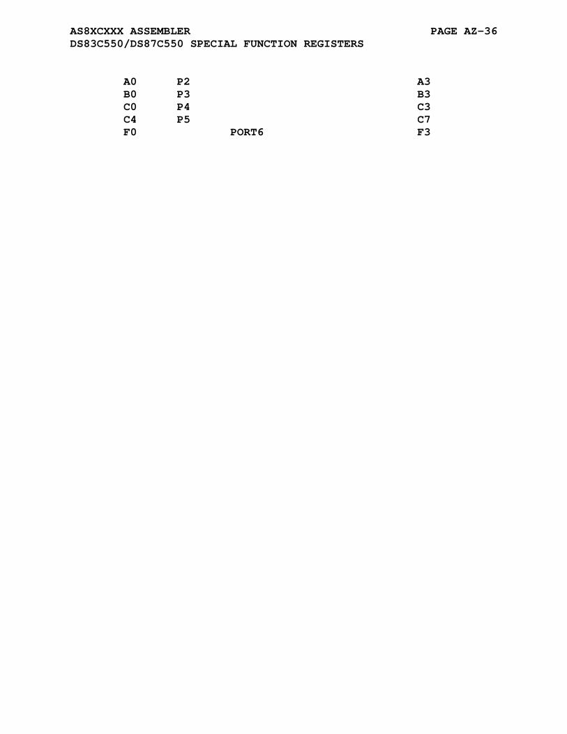
AS8XCXXX ASSEMBLER PAGE AZ-36 DS83C550/DS87C550 SPECIAL FUNCTION REGISTERS
A0 P2 A3 B0 P3 B3 C0 P4 C3 C4 P5 C7 F0 PORT6 F3
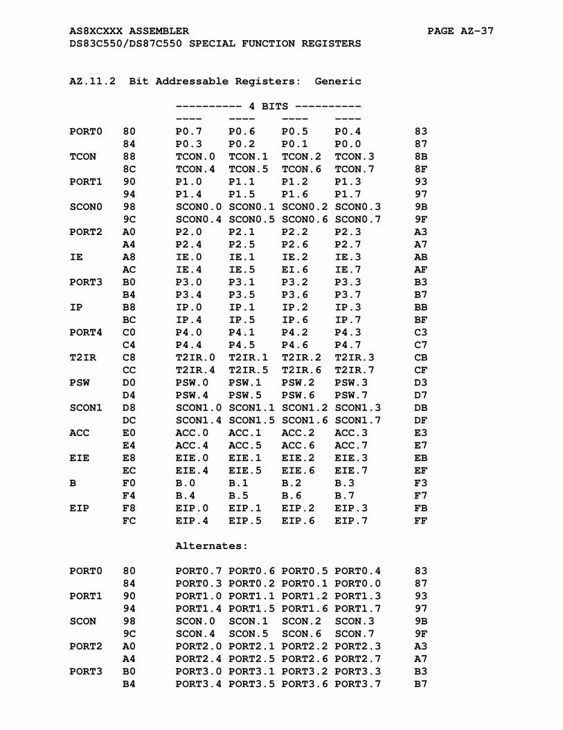
AS8XCXXX ASSEMBLER PAGE AZ-37 DS83C550/DS87C550 SPECIAL FUNCTION REGISTERS
AZ.11.2 Bit Addressable Registers: Generic
---------- 4 BITS ---------- ---- ---- ---- ---- PORT0 80 P0.7 P0.6 P0.5 P0.4 83 84 P0.3 P0.2 P0.1 P0.0 87 TCON 88 TCON.0 TCON.1 TCON.2 TCON.3 8B 8C TCON.4 TCON.5 TCON.6 TCON.7 8F PORT1 90 P1.0 P1.1 P1.2 P1.3 93 94 P1.4 P1.5 P1.6 P1.7 97 SCON0 98 SCON0.0 SCON0.1 SCON0.2 SCON0.3 9B 9C SCON0.4 SCON0.5 SCON0.6 SCON0.7 9F PORT2 A0 P2.0 P2.1 P2.2 P2.3 A3 A4 P2.4 P2.5 P2.6 P2.7 A7 IE A8 IE.0 IE.1 IE.2 IE.3 AB AC IE.4 IE.5 EI.6 IE.7 AF PORT3 B0 P3.0 P3.1 P3.2 P3.3 B3 B4 P3.4 P3.5 P3.6 P3.7 B7 IP B8 IP.0 IP.1 IP.2 IP.3 BB BC IP.4 IP.5 IP.6 IP.7 BF PORT4 C0 P4.0 P4.1 P4.2 P4.3 C3 C4 P4.4 P4.5 P4.6 P4.7 C7 T2IR C8 T2IR.0 T2IR.1 T2IR.2 T2IR.3 CB CC T2IR.4 T2IR.5 T2IR.6 T2IR.7 CF PSW D0 PSW.0 PSW.1 PSW.2 PSW.3 D3 D4 PSW.4 PSW.5 PSW.6 PSW.7 D7 SCON1 D8 SCON1.0 SCON1.1 SCON1.2 SCON1.3 DB DC SCON1.4 SCON1.5 SCON1.6 SCON1.7 DF ACC E0 ACC.0 ACC.1 ACC.2 ACC.3 E3 E4 ACC.4 ACC.5 ACC.6 ACC.7 E7 EIE E8 EIE.0 EIE.1 EIE.2 EIE.3 EB EC EIE.4 EIE.5 EIE.6 EIE.7 EF B F0 B.0 B.1 B.2 B.3 F3 F4 B.4 B.5 B.6 B.7 F7 EIP F8 EIP.0 EIP.1 EIP.2 EIP.3 FB FC EIP.4 EIP.5 EIP.6 EIP.7 FF Alternates: PORT0 80 PORT0.7 PORT0.6 PORT0.5 PORT0.4 83 84 PORT0.3 PORT0.2 PORT0.1 PORT0.0 87 PORT1 90 PORT1.0 PORT1.1 PORT1.2 PORT1.3 93 94 PORT1.4 PORT1.5 PORT1.6 PORT1.7 97 SCON 98 SCON.0 SCON.1 SCON.2 SCON.3 9B 9C SCON.4 SCON.5 SCON.6 SCON.7 9F PORT2 A0 PORT2.0 PORT2.1 PORT2.2 PORT2.3 A3 A4 PORT2.4 PORT2.5 PORT2.6 PORT2.7 A7 PORT3 B0 PORT3.0 PORT3.1 PORT3.2 PORT3.3 B3 B4 PORT3.4 PORT3.5 PORT3.6 PORT3.7 B7
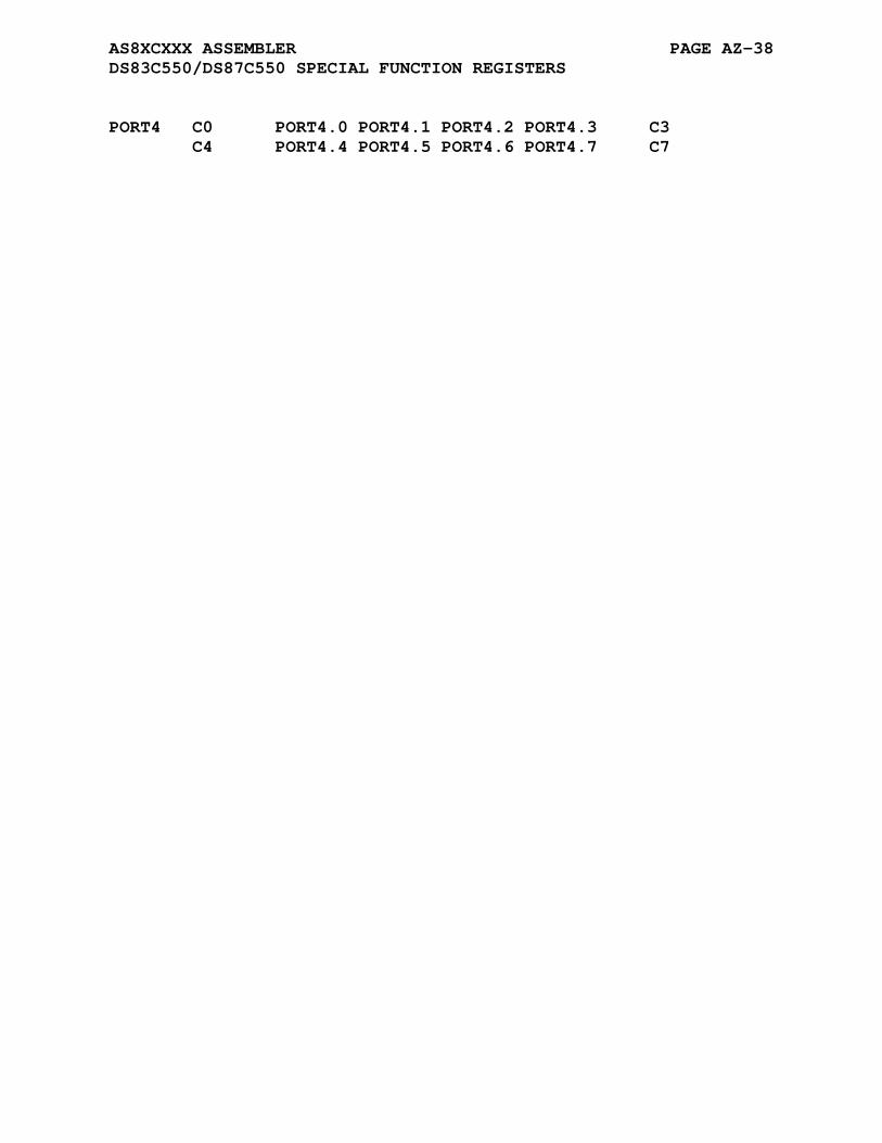
AS8XCXXX ASSEMBLER PAGE AZ-38 DS83C550/DS87C550 SPECIAL FUNCTION REGISTERS
PORT4 C0 PORT4.0 PORT4.1 PORT4.2 PORT4.3 C3 C4 PORT4.4 PORT4.5 PORT4.6 PORT4.7 C7
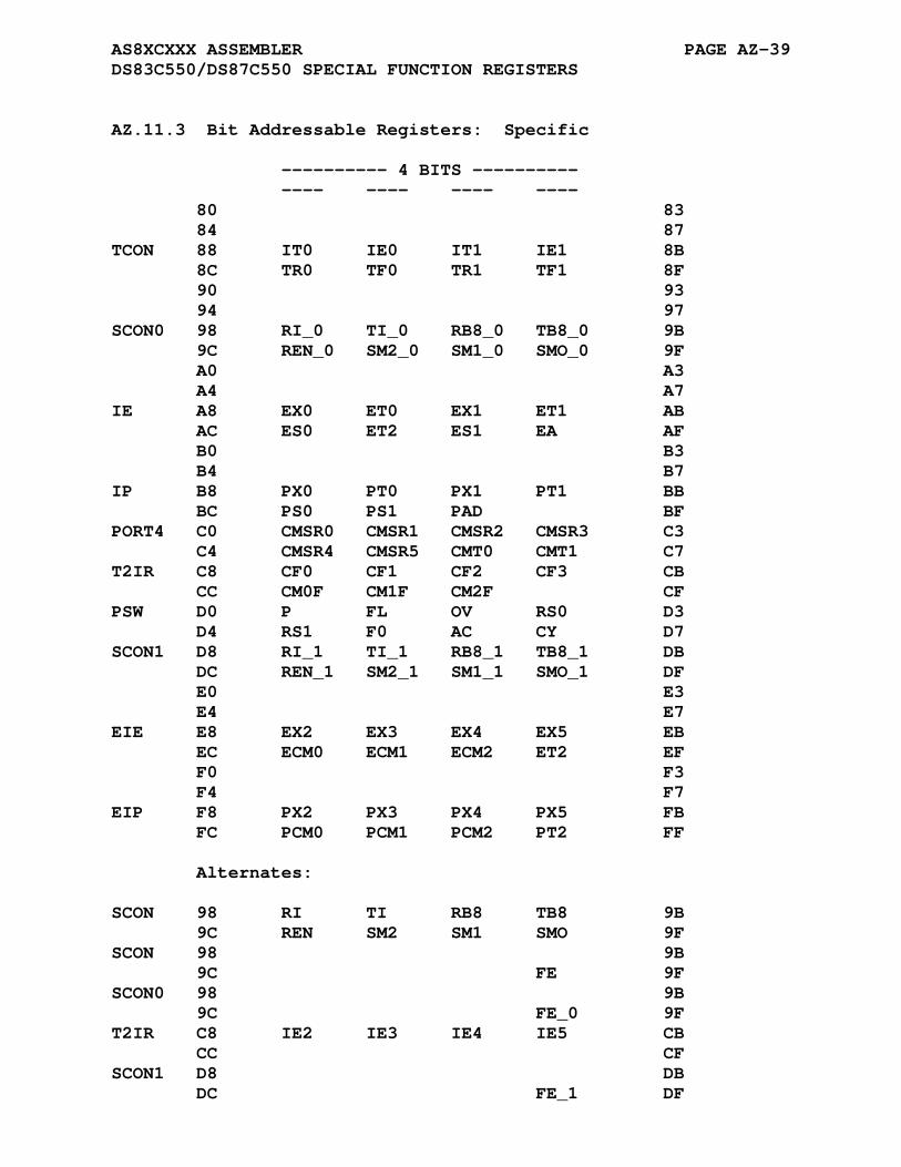
AS8XCXXX ASSEMBLER PAGE AZ-39 DS83C550/DS87C550 SPECIAL FUNCTION REGISTERS
AZ.11.3 Bit Addressable Registers: Specific
---------- 4 BITS ---------- ---- ---- ---- ---- 80 83 84 87 TCON 88 IT0 IE0 IT1 IE1 8B 8C TR0 TF0 TR1 TF1 8F 90 93 94 97 SCON0 98 RI_0 TI_0 RB8_0 TB8_0 9B 9C REN_0 SM2_0 SM1_0 SMO_0 9F A0 A3 A4 A7 IE A8 EX0 ET0 EX1 ET1 AB AC ES0 ET2 ES1 EA AF B0 B3 B4 B7 IP B8 PX0 PT0 PX1 PT1 BB BC PS0 PS1 PAD BF PORT4 C0 CMSR0 CMSR1 CMSR2 CMSR3 C3 C4 CMSR4 CMSR5 CMT0 CMT1 C7 T2IR C8 CF0 CF1 CF2 CF3 CB CC CM0F CM1F CM2F CF PSW D0 P FL OV RS0 D3 D4 RS1 F0 AC CY D7 SCON1 D8 RI_1 TI_1 RB8_1 TB8_1 DB DC REN_1 SM2_1 SM1_1 SMO_1 DF E0 E3 E4 E7 EIE E8 EX2 EX3 EX4 EX5 EB EC ECM0 ECM1 ECM2 ET2 EF F0 F3 F4 F7 EIP F8 PX2 PX3 PX4 PX5 FB FC PCM0 PCM1 PCM2 PT2 FF Alternates: SCON 98 RI TI RB8 TB8 9B 9C REN SM2 SM1 SMO 9F SCON 98 9B 9C FE 9F SCON0 98 9B 9C FE_0 9F T2IR C8 IE2 IE3 IE4 IE5 CB CC CF SCON1 D8 DB DC FE_1 DF
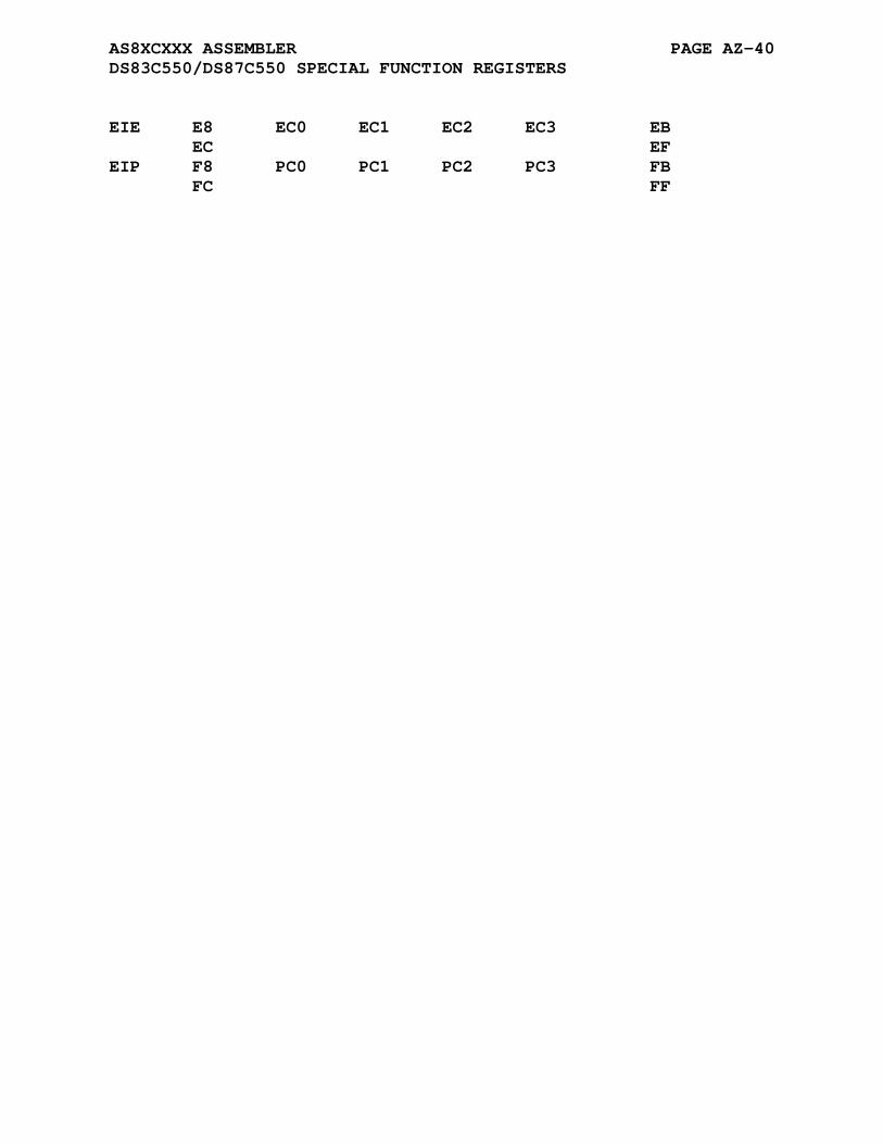
AS8XCXXX ASSEMBLER PAGE AZ-40 DS83C550/DS87C550 SPECIAL FUNCTION REGISTERS
EIE E8 EC0 EC1 EC2 EC3 EB EC EF EIP F8 PC0 PC1 PC2 PC3 FB FC FF
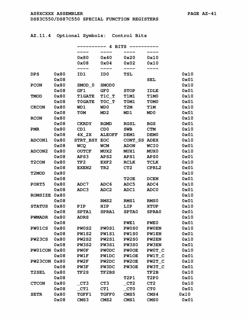
AS8XCXXX ASSEMBLER PAGE AZ-41 DS83C550/DS87C550 SPECIAL FUNCTION REGISTERS
AZ.11.4 Optional Symbols: Control Bits
---------- 4 BITS ---------- ---- ---- ---- ---- 0x80 0x40 0x20 0x10 0x08 0x04 0x02 0x10 ---- ---- ---- ---- DPS 0x80 ID1 ID0 TSL 0x10 0x08 SEL 0x01 PCON 0x80 SMOD_0 SMOD0 0x10 0x08 GF1 GF0 STOP IDLE 0x01 TMOD 0x80 T1GATE T1C_T T1M1 T1M0 0x10 0x08 T0GATE T0C_T T0M1 T0M0 0x01 CKCON 0x80 WD1 WD0 T2M T1M 0x10 0x08 T0M MD2 MD1 MD0 0x01 RCON 0x80 0x10 0x08 CKRDY RGMD RGSL BGS 0x01 PMR 0x80 CD1 CD0 SWB CTM 0x10 0x08 4X_2X ALEOFF DEM1 DEM0 0x01 ADCON1 0x80 STRT_BSY EOC CONT_SS ADEX 0x10 0x08 WCQ WCM ADON WCIO 0x01 ADCON2 0x80 OUTCF MUX2 MUX1 MUX0 0x10 0x08 APS3 APS2 APS1 APS0 0x01 T2CON 0x80 TF2 EXF2 RCLK TCLK 0x10 0x08 EXEN2 TR2 CT2 CPRL2 0x01 T2MOD 0x80 0x10 0x08 T2OE DCEN 0x01 PORT5 0x80 ADC7 ADC6 ADC5 ADC4 0x10 0x08 ADC3 ADC2 ADC1 ADC0 0x01 ROMSIZE 0x80 0x10 0x08 RMS2 RMS1 RMS0 0x01 STATUS 0x80 PIP HIP LIP XTUP 0x10 0x08 SPTA1 SPRA1 SPTA0 SPRA0 0x01 PWMADR 0x80 ADRS 0x10 0x08 PWE1 PWE0 0x01 PW01CS 0x80 PW0S2 PW0S1 PW0S0 PW0EN 0x10 0x08 PW1S2 PW1S1 PW1S0 PW1EN 0x01 PW23CS 0x80 PW2S2 PW2S1 PW2S0 PW2EN 0x10 0x08 PW3S2 PW3S1 PW3S0 PW3EN 0x01 PW01CON 0x80 PW0F PW0DC PW0OE PW0T_C 0x10 0x08 PW1F PW1DC PW1OE PW1T_C 0x01 PW23CON 0x80 PW2F PW2DC PW2OE PW2T_C 0x10 0x08 PW3F PW3DC PW3OE PW3T_C 0x01 T2SEL 0x80 TF2S TF2BS TF2B 0x10 0x08 T2P1 T2P0 0x01 CTCON 0x80 _CT3 CT3 _CT2 CT2 0x10 0x08 _CT1 CT1 _CT0 CT0 0x01 SETR 0x80 TGFF1 TGFF0 CMS5 CMS4 0x10 0x08 CMS3 CMS2 CMS1 CMS0 0x01
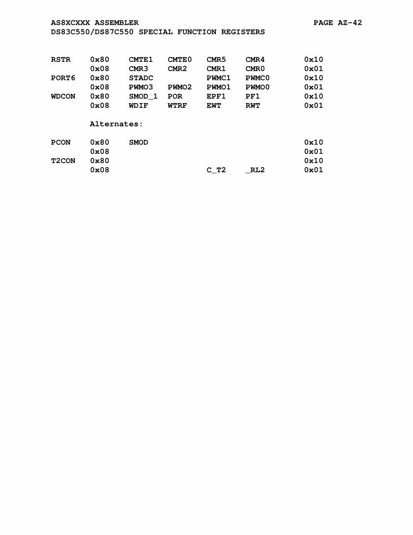
AS8XCXXX ASSEMBLER PAGE AZ-42 DS83C550/DS87C550 SPECIAL FUNCTION REGISTERS
RSTR 0x80 CMTE1 CMTE0 CMR5 CMR4 0x10 0x08 CMR3 CMR2 CMR1 CMR0 0x01 PORT6 0x80 STADC PWMC1 PWMC0 0x10 0x08 PWMO3 PWMO2 PWMO1 PWMO0 0x01 WDCON 0x80 SMOD_1 POR EPF1 PF1 0x10 0x08 WDIF WTRF EWT RWT 0x01 Alternates: PCON 0x80 SMOD 0x10 0x08 0x01 T2CON 0x80 0x10 0x08 C_T2 _RL2 0x01
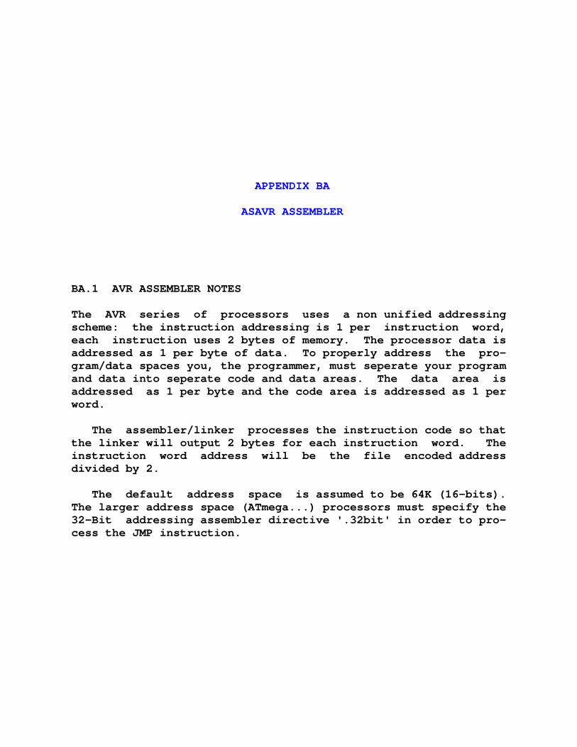
APPENDIX BA
ASAVR ASSEMBLER
BA.1 AVR ASSEMBLER NOTES
The AVR series of processors uses a non unified addressing scheme: the instruction addressing is 1 per instruction word, each instruction uses 2 bytes of memory. The processor data is addressed as 1 per byte of data. To properly address the pro- gram/data spaces you, the programmer, must seperate your program and data into seperate code and data areas. The data area is addressed as 1 per byte and the code area is addressed as 1 per word.
The assembler/linker processes the instruction code so that the linker will output 2 bytes for each instruction word. The instruction word address will be the file encoded address divided by 2.
The default address space is assumed to be 64K (16-bits). The larger address space (ATmega...) processors must specify the 32-Bit addressing assembler directive '.32bit' in order to pro- cess the JMP instruction.
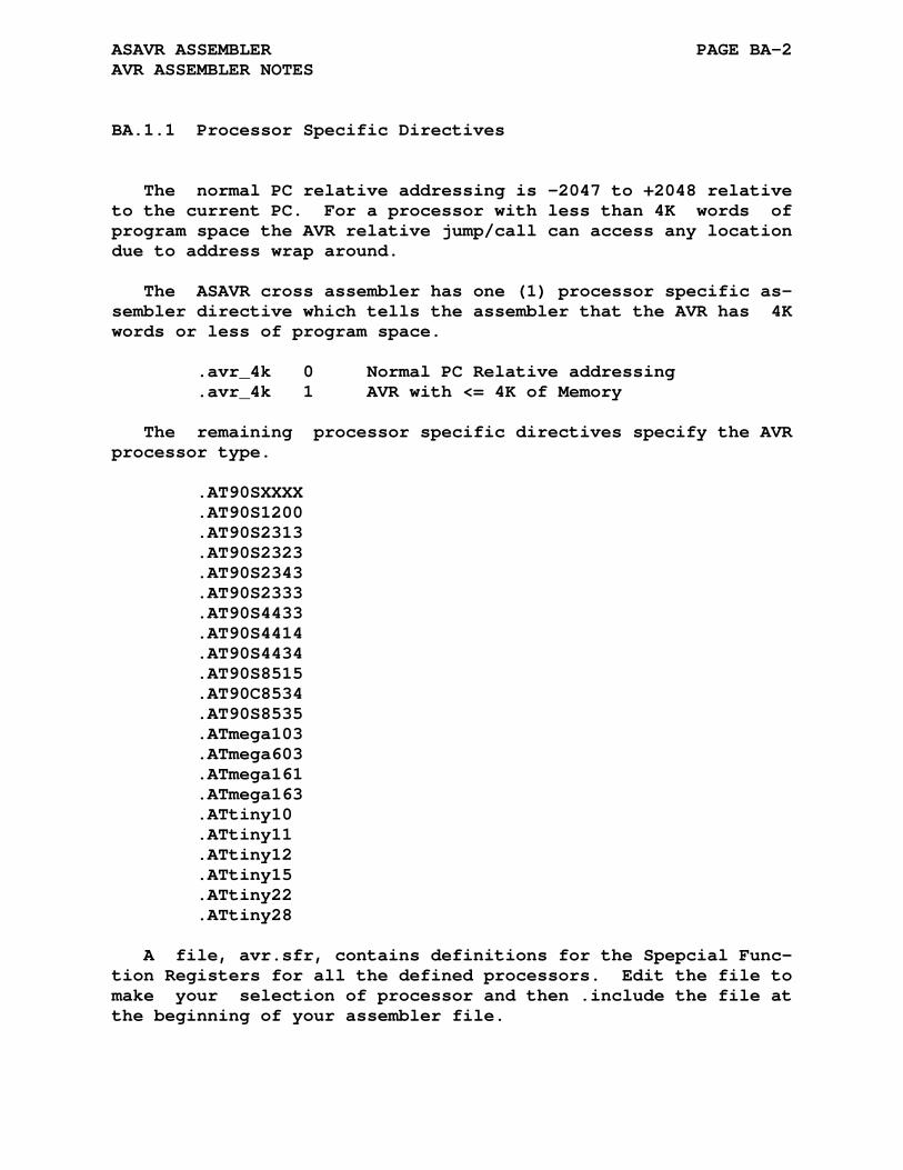
ASAVR ASSEMBLER PAGE BA-2 AVR ASSEMBLER NOTES
BA.1.1 Processor Specific Directives
The normal PC relative addressing is -2047 to +2048 relative to the current PC. For a processor with less than 4K words of program space the AVR relative jump/call can access any location due to address wrap around.
The ASAVR cross assembler has one (1) processor specific as- sembler directive which tells the assembler that the AVR has 4K words or less of program space.
.avr_4k 0 Normal PC Relative addressing .avr_4k 1 AVR with <= 4K of Memory
The remaining processor specific directives specify the AVR processor type.
.AT90SXXXX .AT90S1200 .AT90S2313 .AT90S2323 .AT90S2343 .AT90S2333 .AT90S4433 .AT90S4414 .AT90S4434 .AT90S8515 .AT90C8534 .AT90S8535 .ATmega103 .ATmega603 .ATmega161 .ATmega163 .ATtiny10 .ATtiny11 .ATtiny12 .ATtiny15 .ATtiny22 .ATtiny28
A file, avr.sfr, contains definitions for the Spepcial Func- tion Registers for all the defined processors. Edit the file to make your selection of processor and then .include the file at the beginning of your assembler file.

ASAVR ASSEMBLER PAGE BA-3 AVR ASSEMBLER NOTES
BA.1.2 The .__.CPU. Variable
The value of the pre-defined symbol '.__.CPU.' corresponds to the selected processor type. The default value is 0 which cor- responds to the default processor type. The following table lists the processor types and associated values for the ASAVR assembler:
Processor Type .__.CPU. Value -------------- -------------- Undefined 0 AT90SXXXX (User Defined) 1 AT90S1200 2 AT90S2313 3 AT90S2323 4 AT90S2343 5 AT90S2333 6 AT90S4433 7 AT90S4414 8 AT90S4434 9 AT90S8515 10 AT90C8534 11 AT90S8535 12 ATmega103 13 ATmega603 14 ATmega161 15 ATmega163 16 ATtiny10 17 ATtiny11 18 ATtiny12 19 ATtiny15 20 ATtiny22 21 ATtiny28 22
The variable '.__.CPU.' is by default defined as local and will not be output to the created .rel file. The assembler com- mand line options -g or -a will not cause the local symbol to be output to the created .rel file.
The assembler .globl directive may be used to change the variable type to global causing its definition to be output to the .rel file. The inclusion of the definition of the variable '.__.CPU.' might be a useful means of validating that seperately assembled files have been compiled for the same processor type. The linker will report an error for variables with multiple non equal definitions.
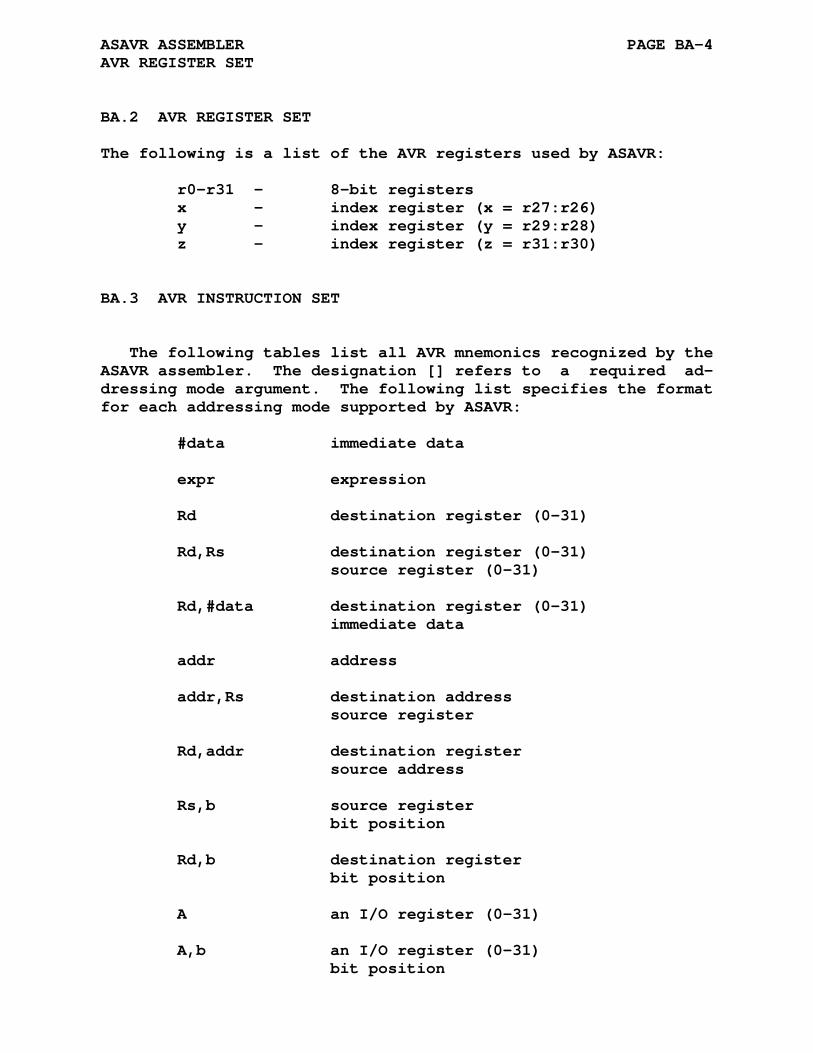
ASAVR ASSEMBLER PAGE BA-4 AVR REGISTER SET
BA.2 AVR REGISTER SET
The following is a list of the AVR registers used by ASAVR:
r0-r31 - 8-bit registers x - index register (x = r27:r26) y - index register (y = r29:r28) z - index register (z = r31:r30)
BA.3 AVR INSTRUCTION SET
The following tables list all AVR mnemonics recognized by the ASAVR assembler. The designation [] refers to a required ad- dressing mode argument. The following list specifies the format for each addressing mode supported by ASAVR:
#data immediate data expr expression Rd destination register (0-31) Rd,Rs destination register (0-31) source register (0-31) Rd,#data destination register (0-31) immediate data addr address addr,Rs destination address source register Rd,addr destination register source address Rs,b source register bit position Rd,b destination register bit position A an I/O register (0-31) A,b an I/O register (0-31) bit position
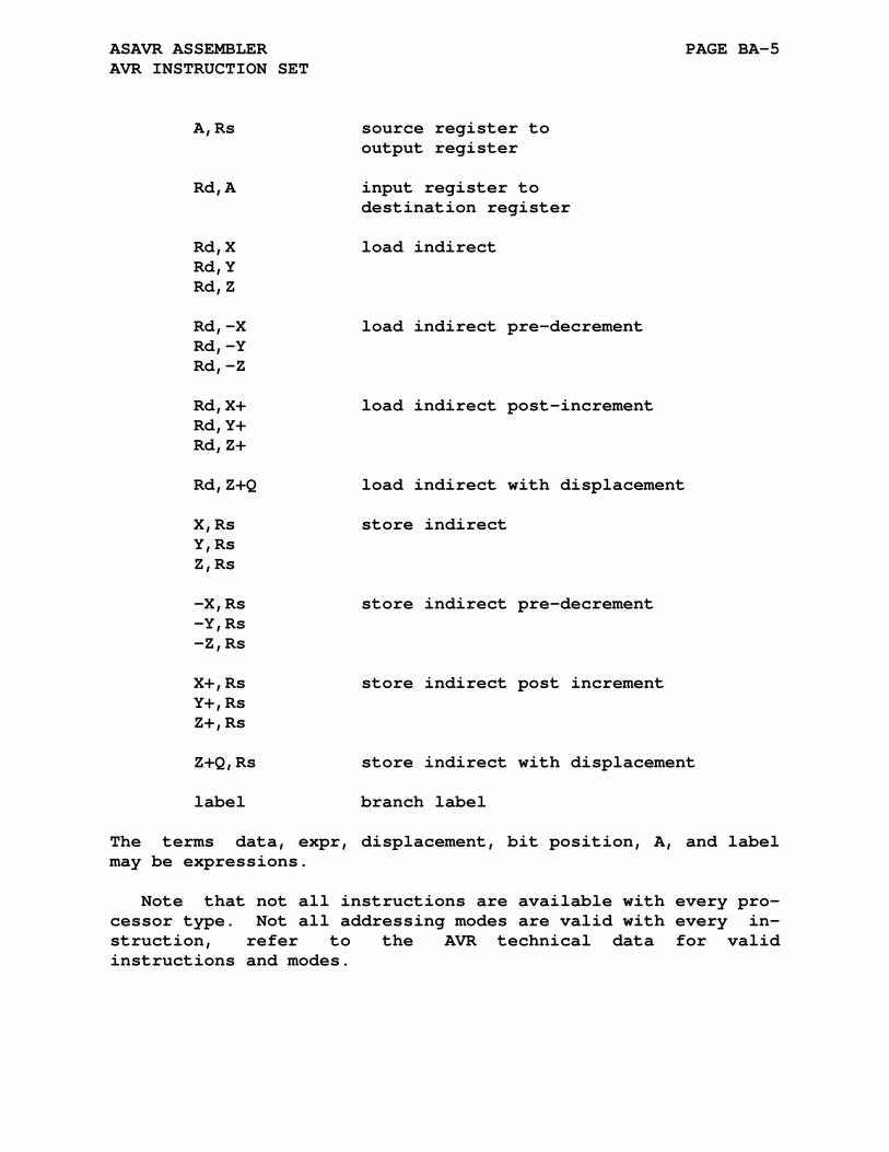
ASAVR ASSEMBLER PAGE BA-5 AVR INSTRUCTION SET
A,Rs source register to output register Rd,A input register to destination register Rd,X load indirect Rd,Y Rd,Z Rd,-X load indirect pre-decrement Rd,-Y Rd,-Z Rd,X+ load indirect post-increment Rd,Y+ Rd,Z+ Rd,Z+Q load indirect with displacement X,Rs store indirect Y,Rs Z,Rs -X,Rs store indirect pre-decrement -Y,Rs -Z,Rs X+,Rs store indirect post increment Y+,Rs Z+,Rs Z+Q,Rs store indirect with displacement label branch label
The terms data, expr, displacement, bit position, A, and label may be expressions.
Note that not all instructions are available with every pro- cessor type. Not all addressing modes are valid with every in- struction, refer to the AVR technical data for valid instructions and modes.

ASAVR ASSEMBLER PAGE BA-6 AVR INSTRUCTION SET
BA.3.1 AVR Arithmetic and Logical Instructions
add Rd,Rs adc Rd,Rs adiw Rd,#data sub Rd,Rs subi Rd,#data sbc Rd,Rs sbci Rd,#data sbiw Rd,#data and Rd,Rs andi Rd,#data or Rd,Rs ori Rd,#data cp Rd,Rs eor Rd,Rs cpi Rd,#data cpc Rd,Rs cbr Rd,#data sbr Rd,#data clr Rd com Rd dec Rd inc Rd neg Rd ser Rd tst Rd mul Rd,Rs fmul Rd,Rs muls Rd,Rs fmuls Rd,Rs mulsu Rd,Rs fmulsu Rd,Rs
BA.3.2 AVR Bit and Bit-Test Instructions
lsl Rd lsr Rd rol Rd ror Rd asr Rd swap Rd bset b bclr b sbi A,b cbi A,b bst Rs,b bld Rd,b sec sez sen sev ses seh set sei clc clz cln clv cls clh clt cli nop sleep wdr

ASAVR ASSEMBLER PAGE BA-7 AVR INSTRUCTION SET
BA.3.3 AVR Skip on Test Instructions
cpse Rd,Rs sbrc Rs,b sbrs Rs,b sbic A,b sbis A,b
BA.3.4 AVR Jump/Call/Return Instructions
jmp addr rjmp addr ijmp eijmp call addr rcall addr icall eicall ret reti
BA.3.5 AVR Short Branch Instructions
brcc label brcs label breq label brge label brhc label brhs label brid label brie label brlo label brlt label brmi label brne label brpl label brsh label brtc label brts label brvc label brvs label
BA.3.6 AVR Short Branch Instructions with Bit Test
brbc b,label brbs b,label
BA.3.7 AVR Data Transfer Instructions
mov Rd,Rs movw Rd,Rs ldi Rd,#data ld [] st [] ldd [] std [] lds Rd,addr sts addr,Rs lpm [] elpm [] spm push Rs pop Rd in Rd,A out A,Rs

APPENDIX BB
ASEZ80 ASSEMBLER
BB.1 ACKNOWLEDGMENT
Thanks to Patrick Head for his contribution of the ASEZ80 cross assembler.
Patrick Head patrick at phead dot net
BB.2 PROCESSOR SPECIFIC DIRECTIVES
The ASEZ80 assembler is a port of the ASZ80 assembler. This assembler can process EZ80 code in Z80 and ADL modes in any com- bination within the source file. The following processor specific assembler directives specify which mode the assembler is to process the assembler source code. The default mode of the assembler is Z80.

ASEZ80 ASSEMBLER PAGE BB-2 PROCESSOR SPECIFIC DIRECTIVES
BB.2.1 .z80 Directive
Format:
.z80 (value)
The .z80 directive without an argument selects the 16-bit Z80 compatible mode of the EZ80 processor. The .z80 directive with the optional argument may be used to select the Z80 16-Bit mode (value != 0) or the EZ80 24-bit mode (value == 0). Mnemonics not allowed in the selected mode will generate <m> (mode) and/or <a> (addressing) errors.
BB.2.2 .adl Directive
Format:
.adl (value)
The .adl directive without an argument selects the 24-bit EZ80 mode of the EZ80 processor. The .adl directive with the op- tional argument may be used to select the EZ80 24-Bit mode (value != 0) or the Z80 16-bit mode (value == 0). Mnemonics not allowed in the selected mode will generate <m> (mode) and/or <a> (addressing) errors.
BB.2.3 .msb Directive
Format:
.msb n
The assembler operator '>' selects the upper byte (MSB) when included in an assembler instruction. The normal assembler mode is to select bits <15:8> as the MSB. The .msb directive allows the programmer to specify a particular byte as the 'MSB' when the address space is larger than 16-bits.
For a 24-bit EZ80 address the assembler directive .msb n con- figures the assembler to select a particular byte as MSB. Given a 24-bit address of Mmn (M is <23:16>, m is <15:8>, and n is <7:0>) the following examples show how to select a particular address byte:
.msb 1 ;select byte 1 of address <M(2):m(1):n(0)>
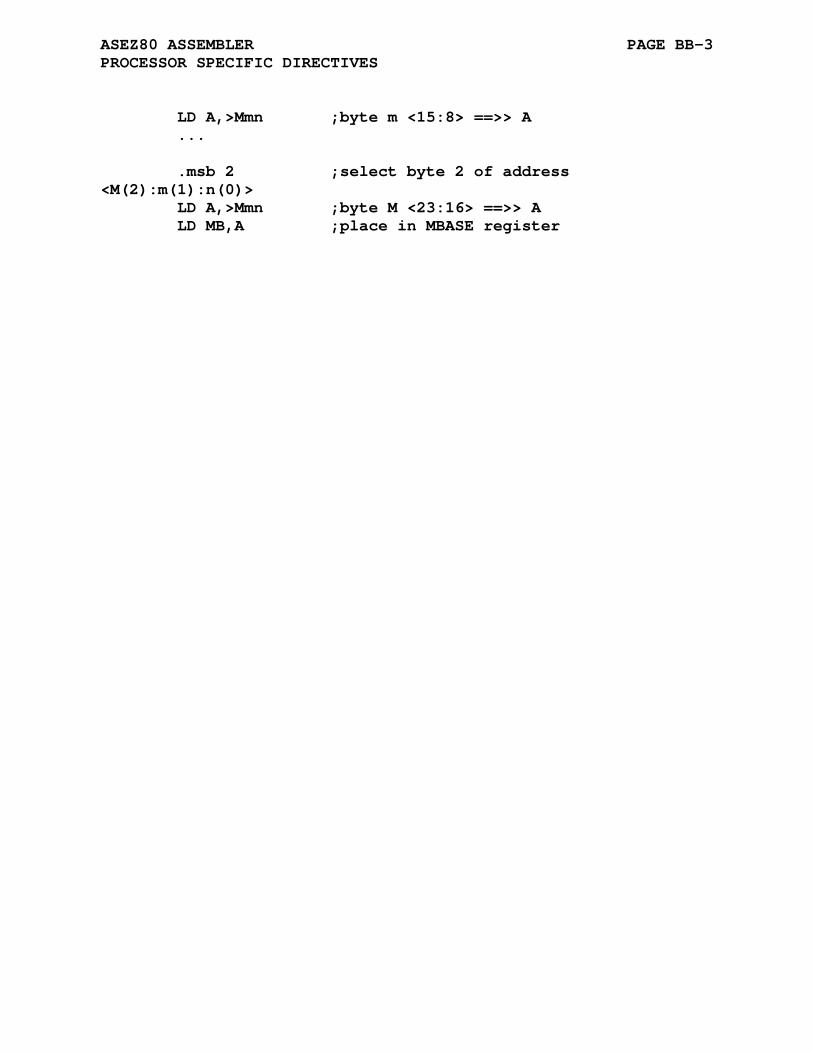
ASEZ80 ASSEMBLER PAGE BB-3 PROCESSOR SPECIFIC DIRECTIVES
LD A,>Mmn ;byte m <15:8> ==>> A ... .msb 2 ;select byte 2 of address <M(2):m(1):n(0)> LD A,>Mmn ;byte M <23:16> ==>> A LD MB,A ;place in MBASE register

ASEZ80 ASSEMBLER PAGE BB-4 PROCESSOR SPECIFIC DIRECTIVES
BB.3 EZ80 ADDRESSING AND INSTRUCTIONS
BB.3.1 Instruction Symbols
b Bit select (000 = bit 0, 001 = bit 1, 010 = bit 2, 011 = bit 3, 100 = bit 4, 101 = bit 5, 110 = bit 6, 111 = bit 7) cc condition code C, NC, Z, NZ, P, M, PE, PO test of single bit in FLAGS register cc' condition code C, NC, Z, NZ test of single bit in FLAGS register d an 8-bit two's complement displacement with value from -128 to 127. I Interrupt Page Address Register ir or ir' 8-bit CPU register IXH(IX:[15:8]), IXL (IX:[7:0], IYH (IY:[15:8]), IYL (IY:[7:0]) IX/Y CPU register IX or IY (IX/Y+d) A location in memory with address formed by the sum of the contents of the Index Register, IX or IY, and the two's complement displacement d. MB Z80 Memory Mode Base Address Register Mmn A 24-bit immediate data value (Mmn) A 24-bit value indicating a location in memory at this address. mn A 16-bit immediate data value (mn) A 16-bit value indicating a location in memory at this address. n 8-bit immediate data value R Refresh Counter Register r or r' 8-bit CPU register A, B, C, D, E, H, L rr 16 or 24-bit CPU register BC, DE, HL rxy 16 or 24-bit CPU register BC, DE, HL, IX, IY SP Stack Pointer, Can indicate either the StackPointer Short register (SPS) or the StackPointer Long register (SPL).
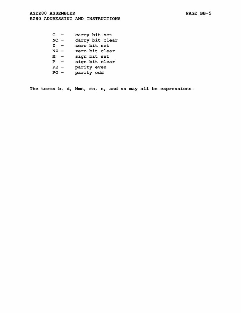
ASEZ80 ASSEMBLER PAGE BB-5 EZ80 ADDRESSING AND INSTRUCTIONS
C - carry bit set NC - carry bit clear Z - zero bit set NZ - zero bit clear M - sign bit set P - sign bit clear PE - parity even PO - parity odd
The terms b, d, Mmn, mn, n, and ss may all be expressions.
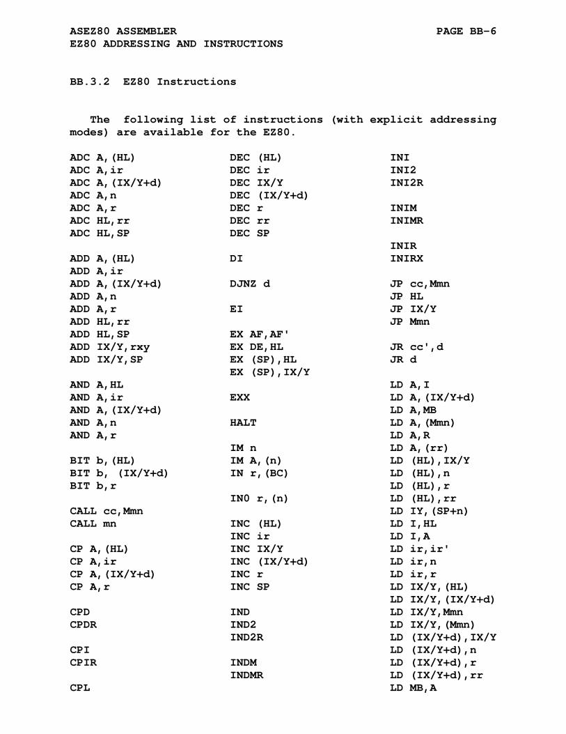
ASEZ80 ASSEMBLER PAGE BB-6 EZ80 ADDRESSING AND INSTRUCTIONS
BB.3.2 EZ80 Instructions
The following list of instructions (with explicit addressing modes) are available for the EZ80.
ADC A,(HL) DEC (HL) INI ADC A,ir DEC ir INI2 ADC A,(IX/Y+d) DEC IX/Y INI2R ADC A,n DEC (IX/Y+d) ADC A,r DEC r INIM ADC HL,rr DEC rr INIMR ADC HL,SP DEC SP INIR ADD A,(HL) DI INIRX ADD A,ir ADD A,(IX/Y+d) DJNZ d JP cc,Mmn ADD A,n JP HL ADD A,r EI JP IX/Y ADD HL,rr JP Mmn ADD HL,SP EX AF,AF' ADD IX/Y,rxy EX DE,HL JR cc',d ADD IX/Y,SP EX (SP),HL JR d EX (SP),IX/Y AND A,HL LD A,I AND A,ir EXX LD A,(IX/Y+d) AND A,(IX/Y+d) LD A,MB AND A,n HALT LD A,(Mmn) AND A,r LD A,R IM n LD A,(rr) BIT b,(HL) IM A,(n) LD (HL),IX/Y BIT b, (IX/Y+d) IN r,(BC) LD (HL),n BIT b,r LD (HL),r IN0 r,(n) LD (HL),rr CALL cc,Mmn LD IY,(SP+n) CALL mn INC (HL) LD I,HL INC ir LD I,A CP A,(HL) INC IX/Y LD ir,ir' CP A,ir INC (IX/Y+d) LD ir,n CP A,(IX/Y+d) INC r LD ir,r CP A,r INC SP LD IX/Y,(HL) LD IX/Y,(IX/Y+d) CPD IND LD IX/Y,Mmn CPDR IND2 LD IX/Y,(Mmn) IND2R LD (IX/Y+d),IX/Y CPI LD (IX/Y+d),n CPIR INDM LD (IX/Y+d),r INDMR LD (IX/Y+d),rr CPL LD MB,A
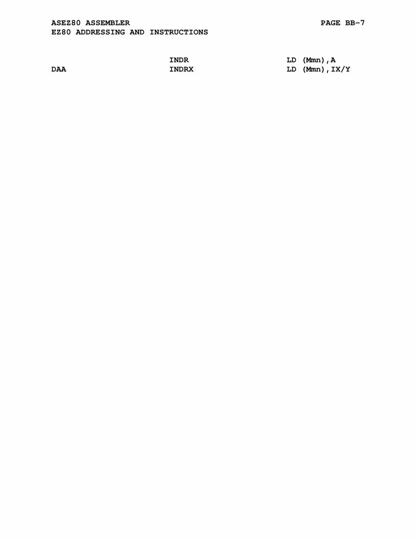
ASEZ80 ASSEMBLER PAGE BB-7 EZ80 ADDRESSING AND INSTRUCTIONS
INDR LD (Mmn),A DAA INDRX LD (Mmn),IX/Y
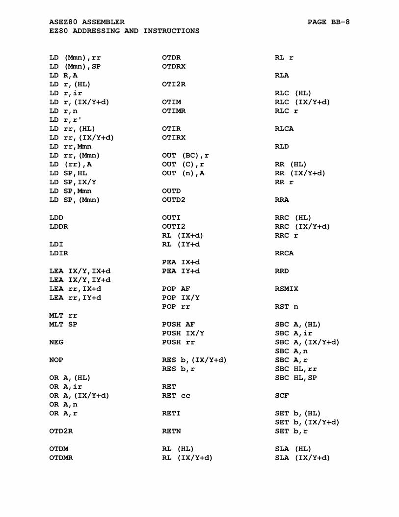
ASEZ80 ASSEMBLER PAGE BB-8 EZ80 ADDRESSING AND INSTRUCTIONS
LD (Mmn),rr OTDR RL r LD (Mmn),SP OTDRX LD R,A RLA LD r,(HL) OTI2R LD r,ir RLC (HL) LD r,(IX/Y+d) OTIM RLC (IX/Y+d) LD r,n OTIMR RLC r LD r,r' LD rr,(HL) OTIR RLCA LD rr,(IX/Y+d) OTIRX LD rr,Mmn RLD LD rr,(Mmn) OUT (BC),r LD (rr),A OUT (C),r RR (HL) LD SP,HL OUT (n),A RR (IX/Y+d) LD SP,IX/Y RR r LD SP,Mmn OUTD LD SP,(Mmn) OUTD2 RRA LDD OUTI RRC (HL) LDDR OUTI2 RRC (IX/Y+d) RL (IX+d) RRC r LDI RL (IY+d LDIR RRCA PEA IX+d LEA IX/Y,IX+d PEA IY+d RRD LEA IX/Y,IY+d LEA rr,IX+d POP AF RSMIX LEA rr,IY+d POP IX/Y POP rr RST n MLT rr MLT SP PUSH AF SBC A,(HL) PUSH IX/Y SBC A,ir NEG PUSH rr SBC A,(IX/Y+d) SBC A,n NOP RES b,(IX/Y+d) SBC A,r RES b,r SBC HL,rr OR A,(HL) SBC HL,SP OR A,ir RET OR A,(IX/Y+d) RET cc SCF OR A,n OR A,r RETI SET b,(HL) SET b,(IX/Y+d) OTD2R RETN SET b,r OTDM RL (HL) SLA (HL) OTDMR RL (IX/Y+d) SLA (IX/Y+d)

ASEZ80 ASSEMBLER PAGE BB-9 EZ80 ADDRESSING AND INSTRUCTIONS
SLA r STMIX TSTIO n SLP SUB A,(HL) XOR A,(HL) SUB A,ir XOR A,ir SRA (HL) SUB A,(IX/Y+d) XOR A,(IX/Y+d) SRA (IX/Y+d) SUB A,n XOR A,n SRA r SUB A,r XOR A,r SRL (HL) TST A,(HL) SRL (IX/Y+d) TST A,n SRL r TST A,r
The accumulator 'A' argument is optional in all of the fol- lowing instructions:
ADC A,... CP A,... SUB A,... ADD A,... OR A,... TST A,... AND A,... SBC A,... XOR A,...
The following tables, organized by instruction type, lists all possible EZ80/Z80 mnemonic extensions recognized by the ASEZ80 assembler. The designation [] refers to a required ad- dressing mode argument shown in the table above. The allowed mnemonic suffixes are denoted within the enclosing delimiters (). Mnemonics specified with illegal or unrecognized suffixs will be flagged with <q> or <a> errors.
BB.3.3 Arithmetic Instructions
adc (.l, .s) [],[] add (.l, .s) [],[] cp (.l, .s) [],[] daa dec (.l, .s) [] inc (.l, .s) [] mlt (.l, .s) [] neg sbc (.l, .s) [],[] sub (.l, .s) [],[]

ASEZ80 ASSEMBLER PAGE BB-10 EZ80 ADDRESSING AND INSTRUCTIONS
BB.3.4 Bit Manipulation Instructions
bit (.l, .s) [],[] res (.l, .s) [],[] set (.l, .s) [],[]
BB.3.5 Block Transfer and Compare Instructions
cpd (.l, .s) cpdr (.l, .s) cpi (.l, .s) cpir (.l, .s) ldd (.l, .s) lddr (.l, .s) ldi (.l, .s) ldir (.l, .s)
BB.3.6 Exchange Instructions
ex (.l, .s) [],[] exx
BB.3.7 Input/Output Instructions
in [],[] in0 [],[] ind (.l, .s) indr (.l, .s) indx (.l, .s) ind2 (.l, .s) ind2r (.l, .s) indm (.l, .s) indmr (.l, .s) ini (.l, .s) inir (.l, .s) inim (.l, .s) inimr (.l, .s) otdm (.l, .s) otdmr (.l, .s) otdrx (.l, .s) otim (.l, .s) otimr (.l, .s) otirx (.l, .s) out (.l, .s) [],[] out0 (.l, .s) [],[] outd (.l, .s) otdr (.l, .s) outd2 (.l, .s) otdr2 (.l, .s) outi (.l, .s) otir (.l, .s) outi2 (.l, .s) oti2r (.l, .s) tstio []

ASEZ80 ASSEMBLER PAGE BB-11 EZ80 ADDRESSING AND INSTRUCTIONS
BB.3.8 Load Instructions
ld (.l, .s, .il, .is, .lil, .sis) [],[] lea (.l, .s) [] pea (.l, .s) [] pop (.l, .s) [] push (.l, .s) []
BB.3.9 Logical Instructions
and (.l, .s) [],[] cpl (.l, .s) or (.l, .s) [],[] tst (.l, .s) [],[] xor (.l, .s) [],[]
BB.3.10 Processor Control Instructions
ccf di ei halt im nop rsmix stmix scf slp
BB.3.11 Program Flow Instructions
call (.il, .is) [] call (.il, .is) CC,[] djnz [] jp (.l, .s, .lil, .sis) [] jp (.l, .s, .lil, .sis) CC,[] jr [] jr CC,[] ret (.l) ret (.l) CC reti (.l) retn (.l) rst (.l, .s) []

ASEZ80 ASSEMBLER PAGE BB-12 EZ80 ADDRESSING AND INSTRUCTIONS
BB.3.12 Shift and Rotate Instructions
rl (.l, .s) [] rla rlc (.l, .s) [] rlca rld rrd rr (.l, .s) [] rra rrc (.1, .s) [] rrca sla (.l, .s) [] sra (.l, .s) [] srl (.l, .s) []
APPENDIX BC
ASF2MC8 ASSEMBLER
BC.1 PROCESSOR SPECIFIC DIRECTIVES
The ASF2MC8 assembler supports the F2MC8L and F2MC8FX proces- sor cores.
BC.1.1 .F2MC8L Directive
Format:
.F2MC8L
The .F2MC8L directive selects the F2MC8L processor cycle counts to be listed. This is the default selection if no processor directive is specified in the source assembly file.
BC.1.2 .F2MC8FX Directive
Format:
.F2MC8FX
The .F2MC8FX directive selects the F2MC8FX processor cycle counts to be listed. .F2MC8L is the default selection if no processor directive is specified in the source assembly file.

ASF2MC8 ASSEMBLER PAGE BC-2 PROCESSOR SPECIFIC DIRECTIVES
BC.1.3 The .__.CPU. Variable
The value of the pre-defined symbol '.__.CPU.' corresponds to the selected processor type. The default value is 0 which cor- responds to the default processor type. The following table lists the processor types and associated values for the ASF2MC8 assembler:
Processor Type .__.CPU. Value -------------- -------------- .F2MC8L 0 .F2MC8FX 1
The variable '.__.CPU.' is by default defined as local and will not be output to the created .rel file. The assembler com- mand line options -g or -a will not cause the local symbol to be output to the created .rel file.
The assembler .globl directive may be used to change the variable type to global causing its definition to be output to the .rel file. The inclusion of the definition of the variable '.__.CPU.' might be a useful means of validating that seperately assembled files have been compiled for the same processor type. The linker will report an error for variables with multiple non equal definitions.
BC.2 F2MC8L/F2MC8FX REGISTERS
The following is a list of register designations recognized by the ASF2MC8 assembler:
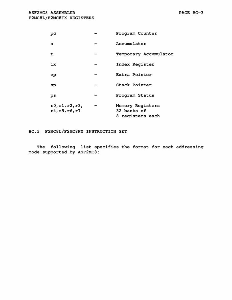
ASF2MC8 ASSEMBLER PAGE BC-3 F2MC8L/F2MC8FX REGISTERS
pc - Program Counter a - Accumulator t - Temporary Accumulator ix - Index Register ep - Extra Pointer sp - Stack Pointer ps - Program Status r0,r1,r2,r3, - Memory Registers r4,r5,r6,r7 32 banks of 8 registers each
BC.3 F2MC8L/F2MC8FX INSTRUCTION SET
The following list specifies the format for each addressing mode supported by ASF2MC8:

ASF2MC8 ASSEMBLER PAGE BC-4 F2MC8L/F2MC8FX INSTRUCTION SET
#data immediate data byte or word data *dir direct page addressing *dir:b bit addressing to a direct page address ext extended addressing a,t register addressing pc,sp,ix,ep @a accumulator indexed @ix+d indexed addressing plus offset @ix indexed addressing with a zero offset @ep pointer addressing r General-purpose registers label call/jmp/branch label
The terms data, dir, ext, b, d, and label may all be expres- sions.
Note that not all addressing modes are valid with every in- struction, refer to the F2MC8L/F2MC8FX technical data for valid modes.
The following tables list all F2MC8L/F2MC8FX mnemonics recog- nized by the ASF2MC8 assembler. The designation [] refers to a required addressing mode argument.
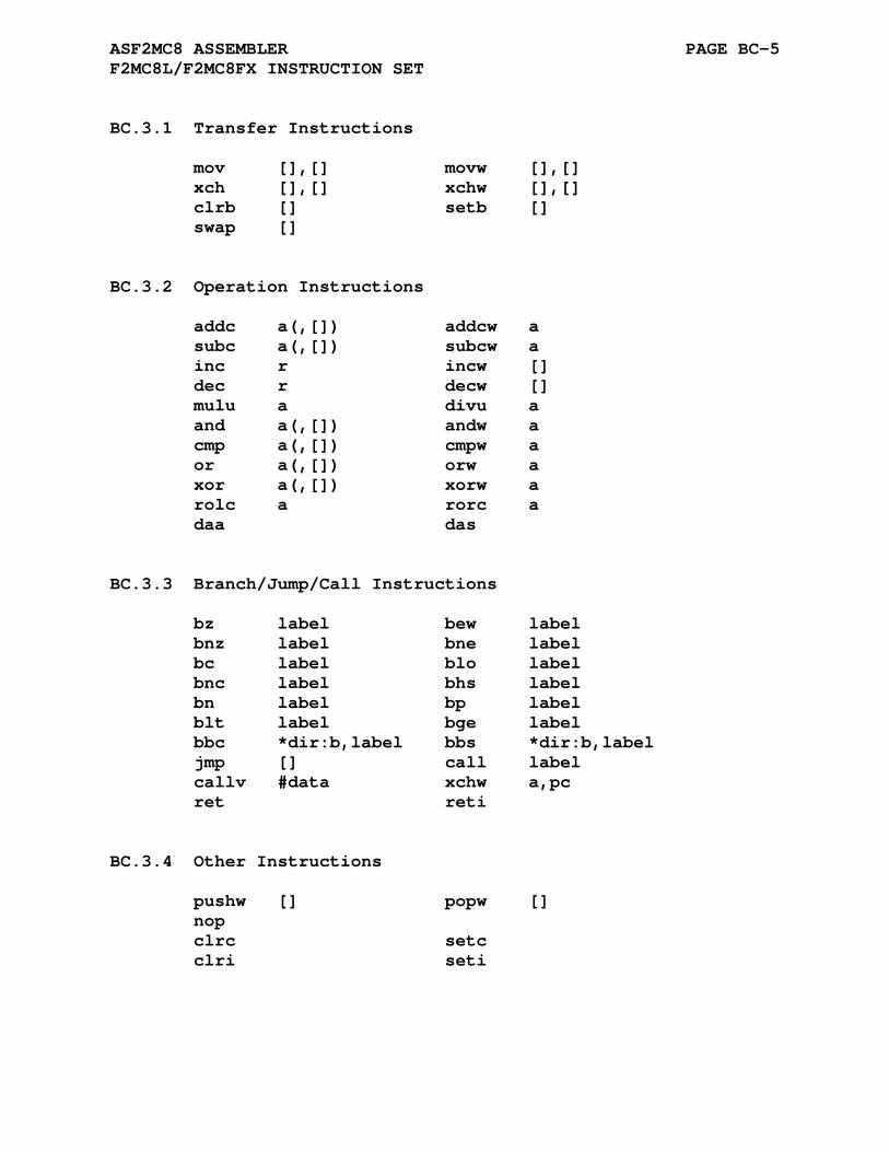
ASF2MC8 ASSEMBLER PAGE BC-5 F2MC8L/F2MC8FX INSTRUCTION SET
BC.3.1 Transfer Instructions
mov [],[] movw [],[] xch [],[] xchw [],[] clrb [] setb [] swap []
BC.3.2 Operation Instructions
addc a(,[]) addcw a subc a(,[]) subcw a inc r incw [] dec r decw [] mulu a divu a and a(,[]) andw a cmp a(,[]) cmpw a or a(,[]) orw a xor a(,[]) xorw a rolc a rorc a daa das
BC.3.3 Branch/Jump/Call Instructions
bz label bew label bnz label bne label bc label blo label bnc label bhs label bn label bp label blt label bge label bbc *dir:b,label bbs *dir:b,label jmp [] call label callv #data xchw a,pc ret reti
BC.3.4 Other Instructions
pushw [] popw [] nop clrc setc clri seti
APPENDIX BD
ASF8 ASSEMBLER
The AS8 assembler supports the F8 and 3870 processor cores.

ASF8 ASSEMBLER Page BD-2
BD.1 F8 REGISTERS
The following is a list of register designations recognized by the ASF8 assembler:

ASF8 ASSEMBLER PAGE BD-3 F8 REGISTERS
r0-r11 - Registers j - Scratch Pad Register r9 hu - MSB of register H the Data Counter Buffer Register Scratch Pad Register r10 hl - LSB of register H the Data Counter Buffer Register Scratch Pad Register r11 ku - MSB of register K the Stack Buffer Register kl - LSB of register K the Stack Buffer Register qu - MSB of register Q a Buffer Register for the Data Counter or Program Counter ql - LSB of register Q a Buffer Register for the Data Counter or Program Counter a - Accumulator is - Scratch Pad Address Register (ISAR) w - Status Register s - Register Addressed by is (unchanged) i - Register Addressed by is (incremented) d - Register Addressed by is (decremented) pc0 - Program Counter or p0, pc pc1 - Program Counter Buffer or or p1, p Stack Register dc0 - Data Counter or d0, dc

ASF8 ASSEMBLER PAGE BD-4 F8 INSTRUCTION SET
BD.2 F8 INSTRUCTION SET
The following list specifies the format for each addressing mode supported by ASF8:
#nibble immediate 4-Bit data #byte immediate 8-Bit data #word immediate 16-Bit data #t3 3-Bit test condition [Zero Carry Sign] #t4 4-Bit test condition [Overflow Zero Carry Sign] r register r0-r11 addressing and indirect addressing s, i, and d j is equivalent to r9 hu (MSB of h) is equivalent to r10 hl (LSB of h) is equivalent to r11 ku and kl MSB and LSB of k register qu and ql MSB and LSB of q register h, k, or q 16-Bit registers p0, pc0, or pc p1 or p d0, dc0, or dc w status register is Indirect Scratchpad Address Register label call/jmp/branch label
The terms nibble, byte, word, t3, t4, and label may all be ex- pressions.
The following tables list all F8 mnemonics recognized by the ASF8 assembler.
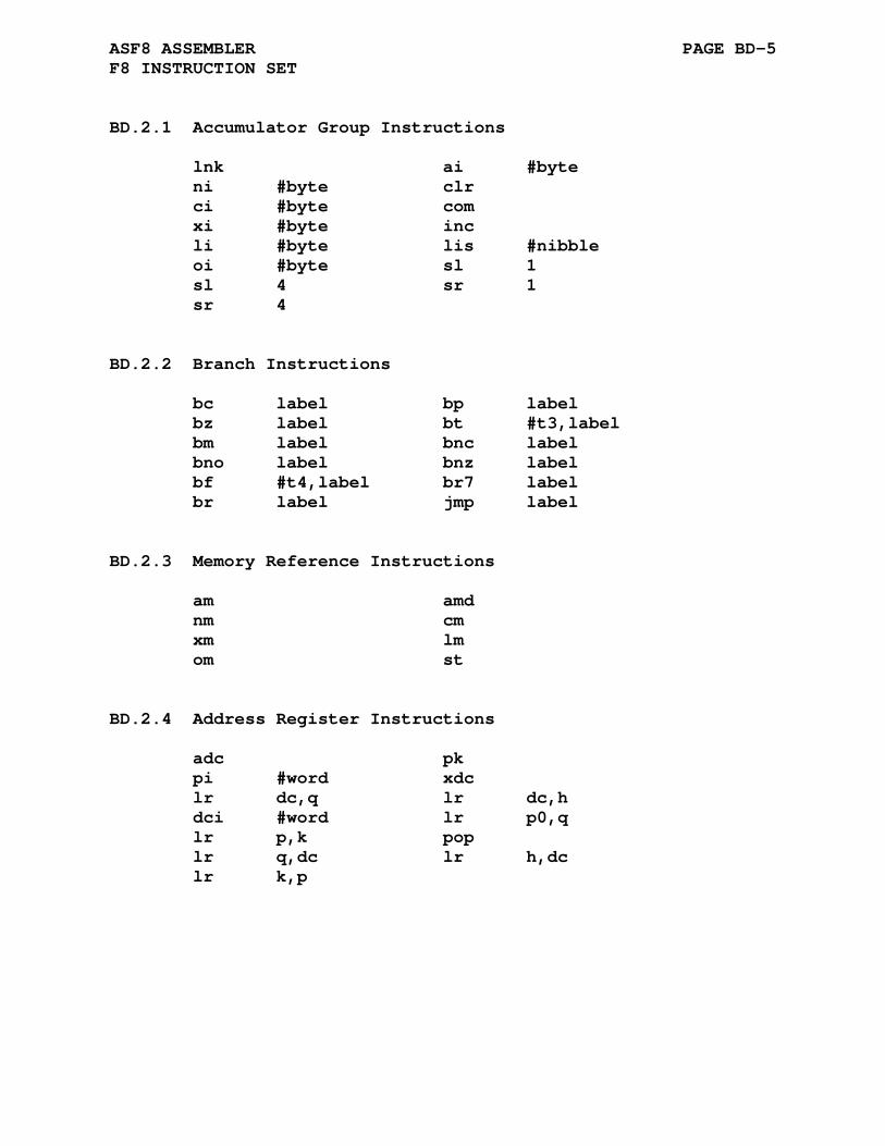
ASF8 ASSEMBLER PAGE BD-5 F8 INSTRUCTION SET
BD.2.1 Accumulator Group Instructions
lnk ai #byte ni #byte clr ci #byte com xi #byte inc li #byte lis #nibble oi #byte sl 1 sl 4 sr 1 sr 4
BD.2.2 Branch Instructions
bc label bp label bz label bt #t3,label bm label bnc label bno label bnz label bf #t4,label br7 label br label jmp label
BD.2.3 Memory Reference Instructions
am amd nm cm xm lm om st
BD.2.4 Address Register Instructions
adc pk pi #word xdc lr dc,q lr dc,h dci #word lr p0,q lr p,k pop lr q,dc lr h,dc lr k,p

ASF8 ASSEMBLER PAGE BD-6 F8 INSTRUCTION SET
BD.2.5 Scratchpad Register Instructions
as r asd r ds r lr a,r lr a,ku lr a,kl lr a,qu lr a,ql lr r,a lr ku,a lr kl,a lr qu,a lr ql,a ns r xs r
BD.2.6 Miscellaneous Instructions
di ei in #byte ins #nibble out #byte outs #nibble lr is,a lr a,is lr w,j lr j,w lisl #0-#7 lisu #0-#7 nop

APPENDIX BE
ASGB ASSEMBLER
BE.1 ACKNOWLEDGEMENT
Thanks to Roger Ivie for his contribution of the ASGB cross assembler.
Roger Ivie ivie at cc dot usu dot edu
BE.2 INTRODUCTION
The Gameboy uses an 8-bit processor which is closely related to the 8080. It is usually described as a modified Z80, but may be more closely understood as an enhanced 8080; it has the 8080 register set and many, but not all, enhanced Z80 instructions. However, even this is not accurate, for the Gameboy also lacks some basic 8080 instructions (most annoyingly SHLD and LHLD). ASGB is based on ASZ80 and therefore uses the Z80 mnemonic set.

ASGB ASSEMBLER PAGE BE-2 GAMEBOY REGISTER SET AND CONDITIONS
BE.3 GAMEBOY REGISTER SET AND CONDITIONS
The following is a complete list of register designations and condition mnemonics:
byte registers - a,b,c,d,e,h,l register pairs - af, bc, de, hl word registers - pc, sp C - carry bit set NC - carry bit clear NZ - zero bit clear Z - zero bit set
BE.4 GAMEBOY INSTRUCTION SET
The following tables list all Gameboy mnemnoics recognized by the ASGB assembler. The designation [] refers to a required ad- dressing mode argument. The following list specifies the format for each addressing mode supported by ASGB:
#data immediate data byte or word data n byte value rg a byte register a,b,c,d,e,h,l rp a register pair or 16-bit register bc,de,hl (hl) implied addressing or register indirect addressing (label) direct addressing label call/jmp/jr label
The terms data, dir, and ext may all be expression. The term dir is not allowed to be an external reference.
Note that not all addressing modes are valid with every in- struction. Although official information is not, as far as I

ASGB ASSEMBLER PAGE BE-3 GAMEBOY INSTRUCTION SET
know, publically available for the Gameboy processor, many unofficial sources are available on the internet.
BE.4.1 .tile Directive
Format:
.tile /string/ or
.tile ^/string/
where: string is a string of ascii characters taken from the set ' ', '.', '+', '*', '0', '1', '2', and '3'. The string must be a multiple of eight characters long.
/ / represent the delimiting characters. These delimiters may be any paired printing characters, as long as the characters are not contained within the string itself. If the delimiting characters do not match, the .tile directive will give the <q> error.
The Gameboy displays information on the screen using a pro- grammable character set (referred to as "tiles" among Gameboy developers). The ASGB cross assembler has a processor-specific assembler directive to aid in the creation of the game's character set.
Each character is created from an 8x8 grid of pixels, each pixel of which is composed of two bits. The .tile directive ac- cepts a single string argument which is processed to create the byte values corresponding to the lines of pixels in the character. The string argument must be some multiple of 8 characters long, and be one of these characters:
' ' or '0' - for the pixel value 00 '.' or '1' - for the pixel value 01 '+' or '2' - for the pixel value 10 '*' or '3' - for the pixel value 11
The .tile directive processes each 8-character group of its string argument to create the two-byte value corresponding to that line of pixels. The example in the popular extant literature could be done using ASGB like this:

ASGB ASSEMBLER PAGE BE-4 GAMEBOY INSTRUCTION SET
0000 7C 7C 1 .tile " ***** " 0002 00 C6 2 .tile "++ ++ " 0004 C6 00 3 .tile ".. .. " 0006 00 FE 4 .tile "+++++++ " 0008 C6 C6 5 .tile "** ** " 000A 00 C6 6 .tile "++ ++ " 000C C6 00 7 .tile ".. .. " 000E 00 00 8 .tile " "
Or, using the synonym character set, as:
0010 7C 7C 10 .tile "03333300" 0012 00 C6 11 .tile "22000220" 0014 C6 00 12 .tile "11000110" 0016 00 FE 13 .tile "22222220" 0018 C6 C6 14 .tile "33000330" 001A 00 C6 15 .tile "22000220" 001C C6 00 16 .tile "11000110" 001E 00 00 17 .tile "00000000"
Since .tile is perfectly willing to assemble multiple lines of a character at once (as long as it is given complete rows of pixels), it could even be done as:
.tile " ***** ++ ++ .. .. +++++++ " .tile "** ** ++ ++ .. .. "
BE.4.2 Potentially Controversial Mnemonic Selection
Although the Gameboy processor is based on the Z80, it does include some features which are not present in the Z80. The Z80 mnemonic set is not sufficient to describe these additional operations; mnemonics must be created for the new operations. The mnemonics ASGB uses are not the same as those used by other publically-available Gameboy assemblers.

ASGB ASSEMBLER PAGE BE-5 GAMEBOY INSTRUCTION SET
BE.4.2.1 Auto-Indexing Loads -
The Gameboy provides instructions to load or store the ac- cumulator indirectly via HL and then subsequently increment or decrement HL. ASGB uses the mnemonic 'ldd' for the instructions which decrement HL and 'ldi' for the instructions which incre- ment HL. Because the Gameboy lacks the Z80's block moves, the mnemonics are not otherwise needed by ASGB.
ldd a,(hl) ldd (hl),a ldi a,(hl) ldi (hl),a
BE.4.2.2 Input and Output Operations -
The Gameboy replaces the Z80's separate address space for I/O with a mechanism similar to the zero page addressing of pro- cessors such as the 6800 or 6502. All I/O registers in the Gameboy reside in the address range between 0xff00 and 0xffff. The Gameboy adds special instructions to load and store the ac- cumulator from and into this page of memory. The instructions are analogous to the Z80's in and out instructions and ASGB re- tains the 'in' and 'out' mnemonics for them.
in a,(n) out (n),a in a,(c) out (c),a
From ASGB's perspective, the RAM available from 0xff80 through 0xffff is composed of unused I/O locations rather than direct-page RAM.
BE.4.2.3 The 'stop' Instruction -
The publically-available documentation for the Gameboy lists the 'stop' instruction as the two-byte instruction 10 00, and the other freely-available Gameboy assemblers assemble it in that manner. As far as I can tell, the only rationale for this is that the corresponding Z80 instruction ('djnz label') is a two-byte instruction. ASGB assembles 'stop' as the one-byte in- struction 10.
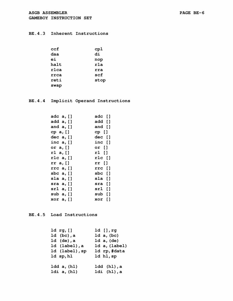
ASGB ASSEMBLER PAGE BE-6 GAMEBOY INSTRUCTION SET
BE.4.3 Inherent Instructions
ccf cpl daa di ei nop halt rla rlca rra rrca scf reti stop swap
BE.4.4 Implicit Operand Instructions
adc a,[] adc [] add a,[] add [] and a,[] and [] cp a,[] cp [] dec a,[] dec [] inc a,[] inc [] or a,[] or [] rl a,[] rl [] rlc a,[] rlc [] rr a,[] rr [] rrc a,[] rrc [] sbc a,[] sbc [] sla a,[] sla [] sra a,[] sra [] srl a,[] srl [] sub a,[] sub [] xor a,[] xor []
BE.4.5 Load Instructions
ld rg,[] ld [],rg ld (bc),a ld a,(bc) ld (de),a ld a,(de) ld (label),a ld a,(label) ld (label),sp ld rp,#data ld sp,hl ld hl,sp ldd a,(hl) ldd (hl),a ldi a,(hl) ldi (hl),a

ASGB ASSEMBLER PAGE BE-7 GAMEBOY INSTRUCTION SET
BE.4.6 Call/Return Instructions
call C,label ret C call NC,label ret NC call Z,label ret Z call NZ,label ret NZ call label ret rst n
BE.4.7 Jump Instructions
jp C,label jp NC,label jp Z,label jp NZ,label jp (hl) jp label jr C,label jr NC,label jr Z,label jr NZ,label jr label
BE.4.8 Bit Manipulation Instructions
bit n,[] res n,[] set n,[]
BE.4.9 Input and Output Instructions
in a,(n) in a,(c) out (n),a out (c),a
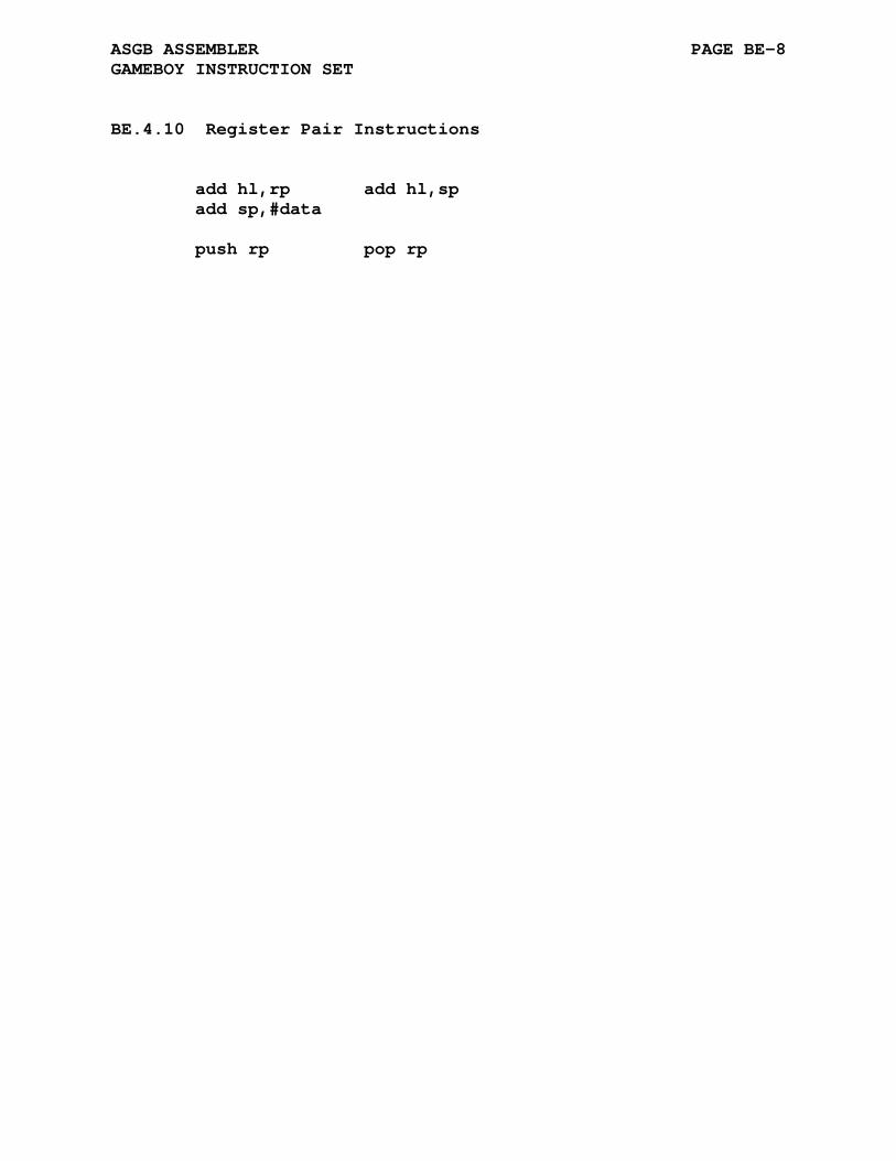
ASGB ASSEMBLER PAGE BE-8 GAMEBOY INSTRUCTION SET
BE.4.10 Register Pair Instructions
add hl,rp add hl,sp add sp,#data push rp pop rp
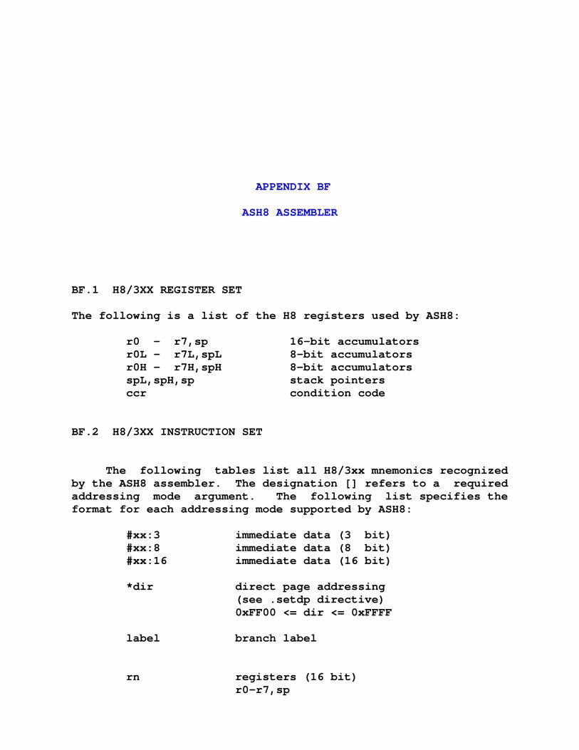
APPENDIX BF
ASH8 ASSEMBLER
BF.1 H8/3XX REGISTER SET
The following is a list of the H8 registers used by ASH8:
r0 - r7,sp 16-bit accumulators r0L - r7L,spL 8-bit accumulators r0H - r7H,spH 8-bit accumulators spL,spH,sp stack pointers ccr condition code
BF.2 H8/3XX INSTRUCTION SET
The following tables list all H8/3xx mnemonics recognized by the ASH8 assembler. The designation [] refers to a required addressing mode argument. The following list specifies the format for each addressing mode supported by ASH8:
#xx:3 immediate data (3 bit) #xx:8 immediate data (8 bit) #xx:16 immediate data (16 bit) *dir direct page addressing (see .setdp directive) 0xFF00 <= dir <= 0xFFFF label branch label rn registers (16 bit) r0-r7,sp

ASH8 ASSEMBLER PAGE BF-2 H8/3XX INSTRUCTION SET
rnB registers (8 bit) r0H-r7H,r0L-r7L,spH,spL ccr condition code register @rn register indirect @-rn register indirect (auto pre-decrement) @rn+ register indirect (auto post-increment) @[offset,rn] register indirect, 16-bit displacement @@offset memory indirect, (8-bit address) ext extended addressing (16-bit)
The terms data, dir, label, offset, and ext may all be expres- sions.
Note that not all addressing modes are valid with every in- struction, refer to the H8/3xx technical data for valid modes.
BF.2.1 Inherent Instructions
eepmov nop sleep rte rts

ASH8 ASSEMBLER PAGE BF-3 H8/3XX INSTRUCTION SET
BF.2.2 Branch Instructions
bcc label bcs label beq label bf label bge label bgt label bhi label bhis label bhs label ble label blo label blos label bls label blt label bmi label bne label bpl label bra label brn label bt label bvc label bvs label bsr label

ASH8 ASSEMBLER PAGE BF-4 H8/3XX INSTRUCTION SET
BF.2.3 Single Operand Instructions
Free Form daa rnB das rnB dec rnB inc rnB neg rnB not rnB rotxl rnB rotxr rnB rotl rnB rotr rnB shal rnB shar rnB shll rnB shlr rnB push rn pop rn Byte / Word Form daa.b rnB das.b rnB dec.b rnB inc.b rnB neg.b rnB not.b rnB rotxl.b rnB rotxr.b rnB rotl.b rnB rotr.b rnB shal.b rnB shar.b rnB shll.b rnB shlr.b rnB push.w rn pop.w rn
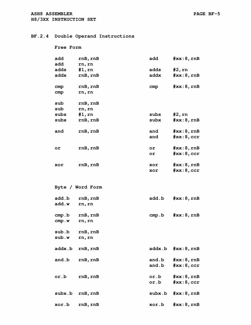
ASH8 ASSEMBLER PAGE BF-5 H8/3XX INSTRUCTION SET
BF.2.4 Double Operand Instructions
Free Form add rnB,rnB add #xx:8,rnB add rn,rn adds #1,rn adds #2,rn addx rnB,rnB addx #xx:8,rnB cmp rnB,rnB cmp #xx:8,rnB cmp rn,rn sub rnB,rnB sub rn,rn subs #1,rn subs #2,rn subx rnB,rnB subx #xx:8,rnB and rnB,rnB and #xx:8,rnB and #xx:8,ccr or rnB,rnB or #xx:8,rnB or #xx:8,ccr xor rnB,rnB xor #xx:8,rnB xor #xx:8,ccr Byte / Word Form add.b rnB,rnB add.b #xx:8,rnB add.w rn,rn cmp.b rnB,rnB cmp.b #xx:8,rnB cmp.w rn,rn sub.b rnB,rnB sub.w rn,rn addx.b rnB,rnB addx.b #xx:8,rnB and.b rnB,rnB and.b #xx:8,rnB and.b #xx:8,ccr or.b rnB,rnB or.b #xx:8,rnB or.b #xx:8,ccr subx.b rnB,rnB subx.b #xx:8,rnB xor.b rnB,rnB xor.b #xx:8,rnB
ASH8 ASSEMBLER PAGE BF-6 H8/3XX INSTRUCTION SET
xor.b #xx:8,ccr

ASH8 ASSEMBLER PAGE BF-7 H8/3XX INSTRUCTION SET
BF.2.5 Mov Instructions
Free Form mov rnB,rnB mov rn,rn mov #xx:8,rnB mov #xx:16,rn mov @rn,rnB mov @rn,rn mov @[offset,rn],rnB mov @[offset,rn],rn mov @rn+,rnB mov @rn+,rn mov @dir,rnB mov dir,rnB mov *@dir,rnB mov *dir,rnB mov @label,rnB mov @label,rn mov label,rnB mov label,rn mov rnB,@rn mov rn,@rn mov rnB,@[offset,rn] mov rn,@[offset,rn] mov rnB,@-rn mov rn,@-rn mov rnB,@dir mov rnB,dir mov rnB,*@dir mov rnB,*dir mov rnB,@label mov rn,@label mov rnB,label mov rn,label Byte / Word Form mov.b rnB,rnB mov.w rn,rn mov.b #xx:8,rnB mov.w #xx:16,rn mov.b @rn,rnB mov.w @rn,rn mov.b @[offset,rn],rnB mov.w @[offset,rn],rn mov.b @rn+,rnB mov.w @rn+,rn mov.b @dir,rnB mov.b dir,rnB mov.b *@dir,rnB mov.b *dir,rnB mov.b @label,rnB mov.w @label,rn mov.b label,rnB mov.w label,rn mov.b rnB,@rn mov.w rn,@rn mov.b rnB,@[offset,rn] mov.w rn,@[offset,rn] mov.b rnB,@-rn mov.w rn,@-rn mov.b rnB,@dir mov.b rnB,dir mov.b rnB,*@dir mov.b rnB,*dir mov.b rnB,@label mov.w rn,@label mov.b rnB,label mov.w rn,label
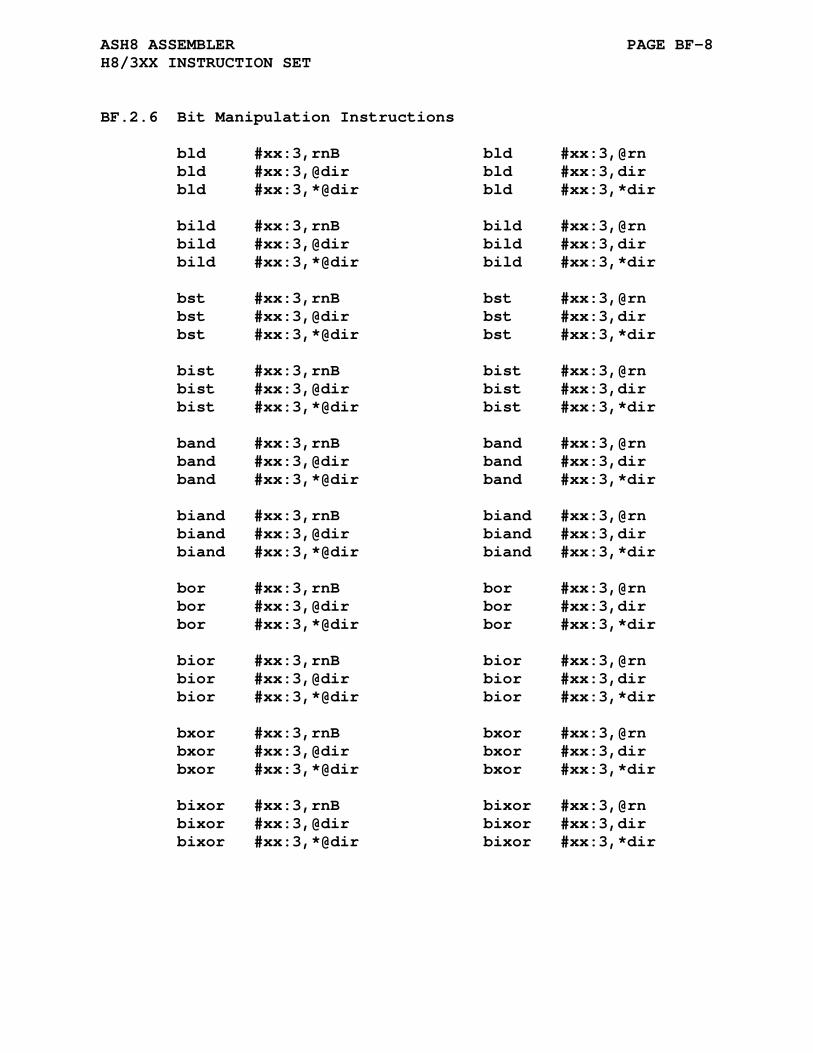
ASH8 ASSEMBLER PAGE BF-8 H8/3XX INSTRUCTION SET
BF.2.6 Bit Manipulation Instructions
bld #xx:3,rnB bld #xx:3,@rn bld #xx:3,@dir bld #xx:3,dir bld #xx:3,*@dir bld #xx:3,*dir bild #xx:3,rnB bild #xx:3,@rn bild #xx:3,@dir bild #xx:3,dir bild #xx:3,*@dir bild #xx:3,*dir bst #xx:3,rnB bst #xx:3,@rn bst #xx:3,@dir bst #xx:3,dir bst #xx:3,*@dir bst #xx:3,*dir bist #xx:3,rnB bist #xx:3,@rn bist #xx:3,@dir bist #xx:3,dir bist #xx:3,*@dir bist #xx:3,*dir band #xx:3,rnB band #xx:3,@rn band #xx:3,@dir band #xx:3,dir band #xx:3,*@dir band #xx:3,*dir biand #xx:3,rnB biand #xx:3,@rn biand #xx:3,@dir biand #xx:3,dir biand #xx:3,*@dir biand #xx:3,*dir bor #xx:3,rnB bor #xx:3,@rn bor #xx:3,@dir bor #xx:3,dir bor #xx:3,*@dir bor #xx:3,*dir bior #xx:3,rnB bior #xx:3,@rn bior #xx:3,@dir bior #xx:3,dir bior #xx:3,*@dir bior #xx:3,*dir bxor #xx:3,rnB bxor #xx:3,@rn bxor #xx:3,@dir bxor #xx:3,dir bxor #xx:3,*@dir bxor #xx:3,*dir bixor #xx:3,rnB bixor #xx:3,@rn bixor #xx:3,@dir bixor #xx:3,dir bixor #xx:3,*@dir bixor #xx:3,*dir
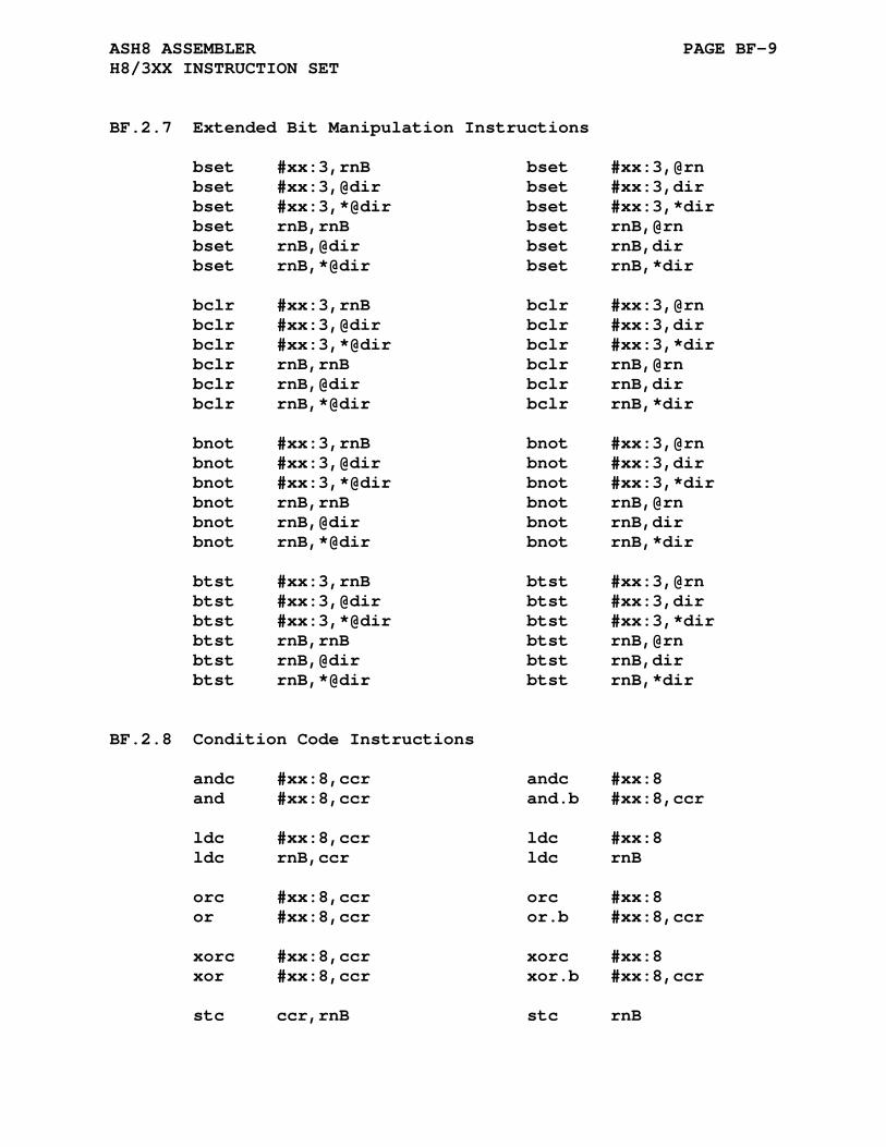
ASH8 ASSEMBLER PAGE BF-9 H8/3XX INSTRUCTION SET
BF.2.7 Extended Bit Manipulation Instructions
bset #xx:3,rnB bset #xx:3,@rn bset #xx:3,@dir bset #xx:3,dir bset #xx:3,*@dir bset #xx:3,*dir bset rnB,rnB bset rnB,@rn bset rnB,@dir bset rnB,dir bset rnB,*@dir bset rnB,*dir bclr #xx:3,rnB bclr #xx:3,@rn bclr #xx:3,@dir bclr #xx:3,dir bclr #xx:3,*@dir bclr #xx:3,*dir bclr rnB,rnB bclr rnB,@rn bclr rnB,@dir bclr rnB,dir bclr rnB,*@dir bclr rnB,*dir bnot #xx:3,rnB bnot #xx:3,@rn bnot #xx:3,@dir bnot #xx:3,dir bnot #xx:3,*@dir bnot #xx:3,*dir bnot rnB,rnB bnot rnB,@rn bnot rnB,@dir bnot rnB,dir bnot rnB,*@dir bnot rnB,*dir btst #xx:3,rnB btst #xx:3,@rn btst #xx:3,@dir btst #xx:3,dir btst #xx:3,*@dir btst #xx:3,*dir btst rnB,rnB btst rnB,@rn btst rnB,@dir btst rnB,dir btst rnB,*@dir btst rnB,*dir
BF.2.8 Condition Code Instructions
andc #xx:8,ccr andc #xx:8 and #xx:8,ccr and.b #xx:8,ccr ldc #xx:8,ccr ldc #xx:8 ldc rnB,ccr ldc rnB orc #xx:8,ccr orc #xx:8 or #xx:8,ccr or.b #xx:8,ccr xorc #xx:8,ccr xorc #xx:8 xor #xx:8,ccr xor.b #xx:8,ccr stc ccr,rnB stc rnB

ASH8 ASSEMBLER PAGE BF-10 H8/3XX INSTRUCTION SET
BF.2.9 Other Instructions
divxu rnB,rn divxu.b rnB,rn mulxu rnB,rn mulxu.b rnB,rn movfpe @label,rnB movfpe label,rnB movfpe.b @label,rnB movfpe.b label,rnB movtpe @label,rnB movtpe label,rnB movtpe.b @label,rnB movtpe.b label,rnB
BF.2.10 Jump and Jump to Subroutine Instructions
jmp @rn jmp @@dir jmp @label jmp label jsr @rn jsr @@dir jsr @label jsr label

APPENDIX BG
ASM8C ASSEMBLER
BG.1 M8C REGISTER SET
The following is a list of the M8C registers used by ASM8C:
A - Accumulator X - Index SP - Stack Pointer F - Flags
BG.2 M8C ADDRESSING MODES
The M8C instructions may have none, one, or two operands selected from the registers listed above or an addressing mode from the following list:
expr - immediate argument - In the lcall, ljmp, index, and pc relative branching instructions expr is an address expression. #expr - immediate argument [expr] - argument at location expr [x+expr] - argument at location x + expr reg[expr] - argument at location expr in register space reg[x+expr] - argument at location x + expr in register space [[expr]++] - The value in memory at address expr (the indirect address) points to a memory location in RAM. The value in memory at

ASM8C ASSEMBLER PAGE BG-2 M8C ADDRESSING MODES
address expr is then incremented. This addressing mode is used only by the mvi instruction and allows the short form [expr] for this addressing mode.
BG.3 M8C INSTRUCTION SET
The following tables list all M8C mnemonics and addressing modes recognized by the ASM8C assembler.
BG.3.1 Double Operand Arithmetic Instructions
adc a,expr adc a,[expr] adc [expr],a adc a,[x+expr] adc [x+expr],a adc [expr],expr adc [x+expr],expr add a,expr add a,[expr] add [expr],a add a,[x+expr] add [x+expr],a add [expr],expr add [x+expr],expr add sp,expr cmp a,expr cmp a,[expr] cmp a,[x+expr] cmp [expr],expr cmp [x+expr],expr sbb a,expr sbb a,[expr] sbb [expr],a sbb a,[x+expr] sbb [x+expr],a sbb [expr],expr sbb [x+expr],expr sub a,expr sub a,[expr] sub [expr],a sub a,[x+expr] sub [x+expr],a sub [expr],expr sub [x+expr],expr
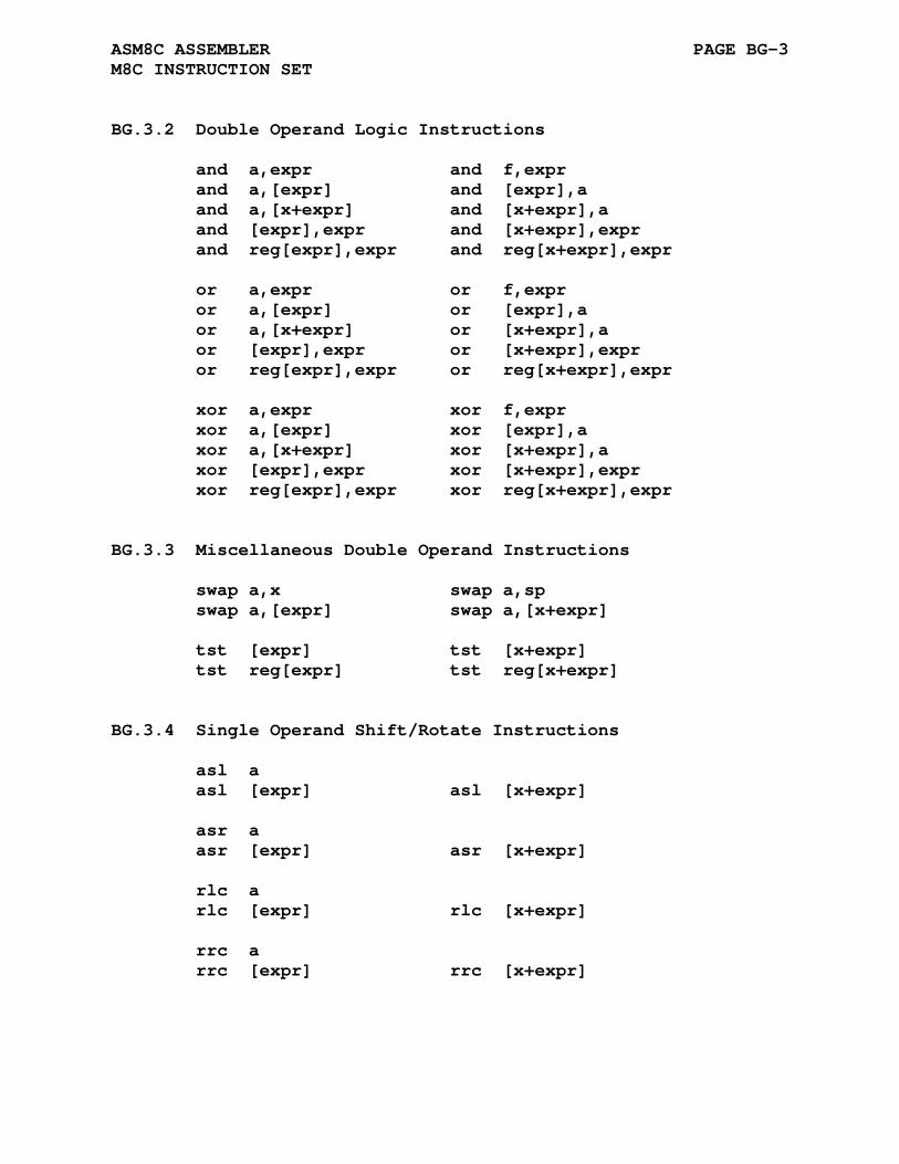
ASM8C ASSEMBLER PAGE BG-3 M8C INSTRUCTION SET
BG.3.2 Double Operand Logic Instructions
and a,expr and f,expr and a,[expr] and [expr],a and a,[x+expr] and [x+expr],a and [expr],expr and [x+expr],expr and reg[expr],expr and reg[x+expr],expr or a,expr or f,expr or a,[expr] or [expr],a or a,[x+expr] or [x+expr],a or [expr],expr or [x+expr],expr or reg[expr],expr or reg[x+expr],expr xor a,expr xor f,expr xor a,[expr] xor [expr],a xor a,[x+expr] xor [x+expr],a xor [expr],expr xor [x+expr],expr xor reg[expr],expr xor reg[x+expr],expr
BG.3.3 Miscellaneous Double Operand Instructions
swap a,x swap a,sp swap a,[expr] swap a,[x+expr] tst [expr] tst [x+expr] tst reg[expr] tst reg[x+expr]
BG.3.4 Single Operand Shift/Rotate Instructions
asl a asl [expr] asl [x+expr] asr a asr [expr] asr [x+expr] rlc a rlc [expr] rlc [x+expr] rrc a rrc [expr] rrc [x+expr]
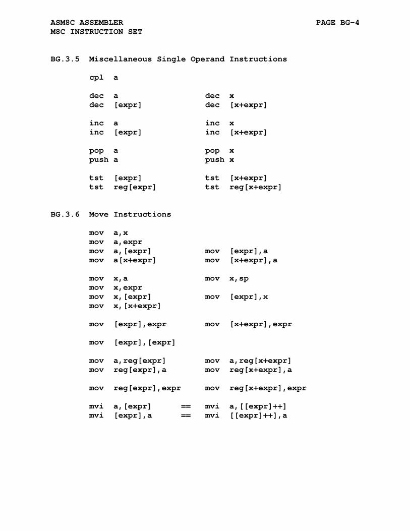
ASM8C ASSEMBLER PAGE BG-4 M8C INSTRUCTION SET
BG.3.5 Miscellaneous Single Operand Instructions
cpl a dec a dec x dec [expr] dec [x+expr] inc a inc x inc [expr] inc [x+expr] pop a pop x push a push x tst [expr] tst [x+expr] tst reg[expr] tst reg[x+expr]
BG.3.6 Move Instructions
mov a,x mov a,expr mov a,[expr] mov [expr],a mov a[x+expr] mov [x+expr],a mov x,a mov x,sp mov x,expr mov x,[expr] mov [expr],x mov x,[x+expr] mov [expr],expr mov [x+expr],expr mov [expr],[expr] mov a,reg[expr] mov a,reg[x+expr] mov reg[expr],a mov reg[x+expr],a mov reg[expr],expr mov reg[x+expr],expr mvi a,[expr] == mvi a,[[expr]++] mvi [expr],a == mvi [[expr]++],a

ASM8C ASSEMBLER PAGE BG-5 M8C INSTRUCTION SET
BG.3.7 Inherent Instructions
halt nop romx ssc ret reti
BG.3.8 Branching Instructions
lcall expr ljmp expr jz expr jnz expr jc expr jnc expr jacc expr
BG.3.9 Relative Table Read Instruction
index expr

APPENDIX BH
ASPIC ASSEMBLER
BH.1 PIC ASSEMBLER NOTES
The PIC series of processors uses a non unified addressing scheme: the instruction addressing is 1 per instruction word, each instruction uses a word of memory varying from 12 to 16 bits in length. The processor data is addressed as 1 per byte of data. To properly address the program/data spaces you, the programmer, must seperate your program and data into seperate code and data areas. The data area is addressed as 1 per byte and the code area is addressed as 1 per instruction.
The assembler/linker processes the instruction code so that the linker will output 2 bytes for each instruction word. The instruction word address will be the file encoded address divided by 2.
BH.2 PROCESSOR SPECIFIC DIRECTIVES
The ASPIC assembler has several processor specific assem- bler directives. These directives specify a processor name, select a PIC processor family type, define the maximum ram ad- dress, specify ram addresses that should not be accessed, and define the register file address page.
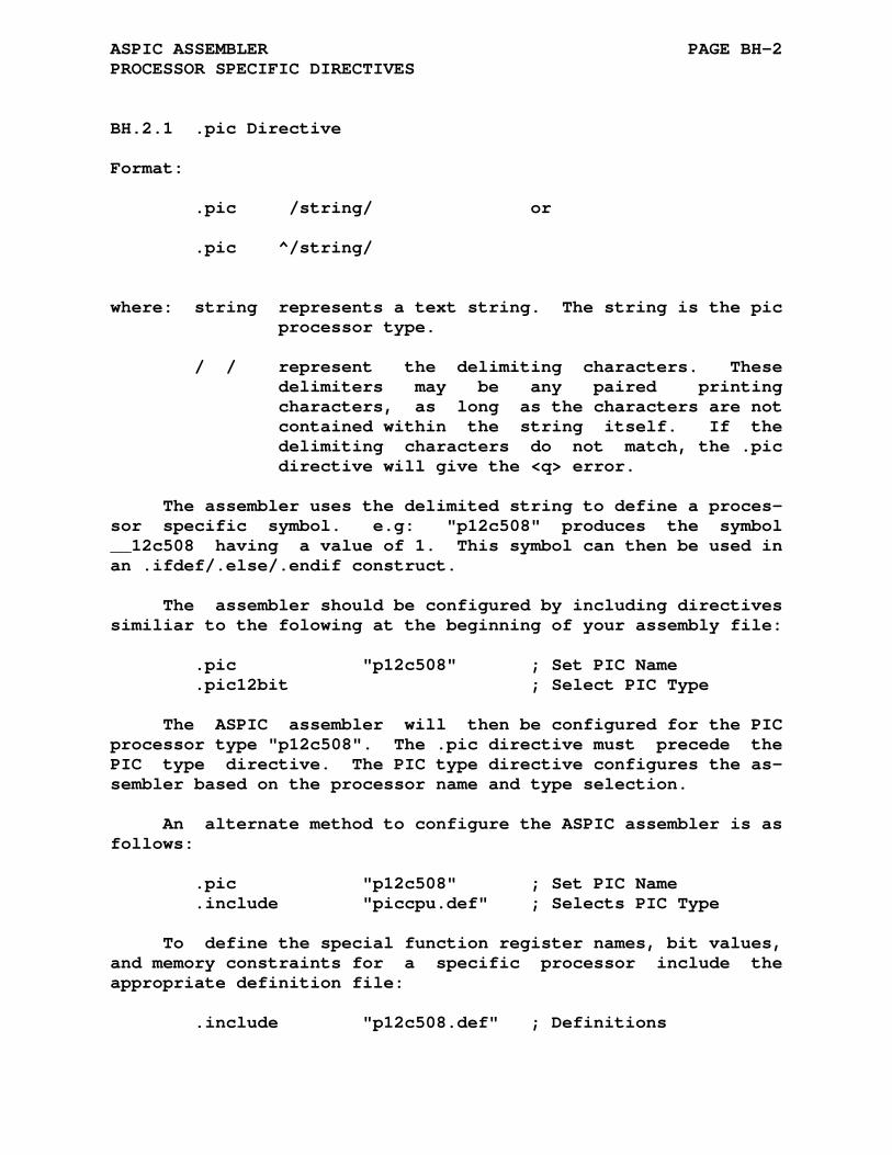
ASPIC ASSEMBLER PAGE BH-2 PROCESSOR SPECIFIC DIRECTIVES
BH.2.1 .pic Directive
Format:
.pic /string/ or
.pic ^/string/
where: string represents a text string. The string is the pic processor type.
/ / represent the delimiting characters. These delimiters may be any paired printing characters, as long as the characters are not contained within the string itself. If the delimiting characters do not match, the .pic directive will give the <q> error.
The assembler uses the delimited string to define a proces- sor specific symbol. e.g: "p12c508" produces the symbol __12c508 having a value of 1. This symbol can then be used in an .ifdef/.else/.endif construct.
The assembler should be configured by including directives similiar to the folowing at the beginning of your assembly file:
.pic "p12c508" ; Set PIC Name .pic12bit ; Select PIC Type
The ASPIC assembler will then be configured for the PIC processor type "p12c508". The .pic directive must precede the PIC type directive. The PIC type directive configures the as- sembler based on the processor name and type selection.
An alternate method to configure the ASPIC assembler is as follows:
.pic "p12c508" ; Set PIC Name .include "piccpu.def" ; Selects PIC Type
To define the special function register names, bit values, and memory constraints for a specific processor include the appropriate definition file:
.include "p12c508.def" ; Definitions
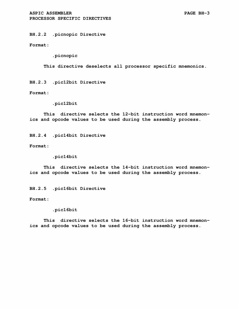
ASPIC ASSEMBLER PAGE BH-3 PROCESSOR SPECIFIC DIRECTIVES
BH.2.2 .picnopic Directive
Format:
.picnopic
This directive deselects all processor specific mnemonics.
BH.2.3 .pic12bit Directive
Format:
.pic12bit
This directive selects the 12-bit instruction word mnemon- ics and opcode values to be used during the assembly process.
BH.2.4 .pic14bit Directive
Format:
.pic14bit
This directive selects the 14-bit instruction word mnemon- ics and opcode values to be used during the assembly process.
BH.2.5 .pic16bit Directive
Format:
.pic16bit
This directive selects the 16-bit instruction word mnemon- ics and opcode values to be used during the assembly process.
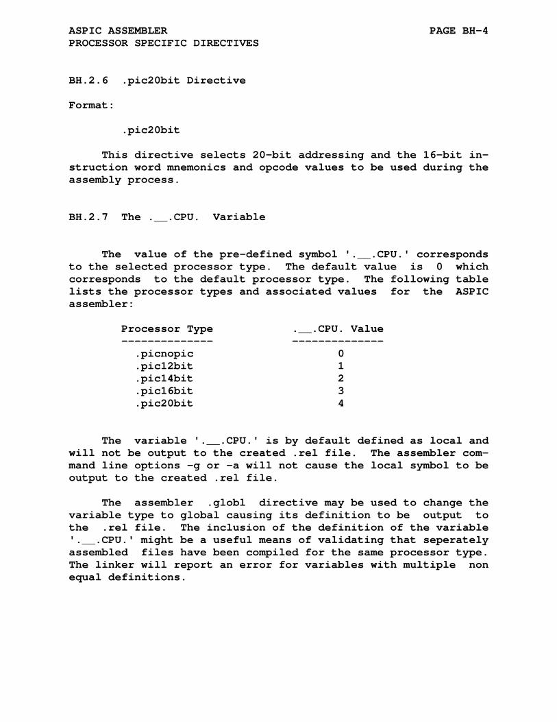
ASPIC ASSEMBLER PAGE BH-4 PROCESSOR SPECIFIC DIRECTIVES
BH.2.6 .pic20bit Directive
Format:
.pic20bit
This directive selects 20-bit addressing and the 16-bit in- struction word mnemonics and opcode values to be used during the assembly process.
BH.2.7 The .__.CPU. Variable
The value of the pre-defined symbol '.__.CPU.' corresponds to the selected processor type. The default value is 0 which corresponds to the default processor type. The following table lists the processor types and associated values for the ASPIC assembler:
Processor Type .__.CPU. Value -------------- -------------- .picnopic 0 .pic12bit 1 .pic14bit 2 .pic16bit 3 .pic20bit 4
The variable '.__.CPU.' is by default defined as local and will not be output to the created .rel file. The assembler com- mand line options -g or -a will not cause the local symbol to be output to the created .rel file.
The assembler .globl directive may be used to change the variable type to global causing its definition to be output to the .rel file. The inclusion of the definition of the variable '.__.CPU.' might be a useful means of validating that seperately assembled files have been compiled for the same processor type. The linker will report an error for variables with multiple non equal definitions.

ASPIC ASSEMBLER PAGE BH-5 PROCESSOR SPECIFIC DIRECTIVES
BH.2.8 .picfix Directive
Format:
.picfix chip, mnemonic, value
This directive can be used to "fix" or change the opcode value of any pic instruction of the currently selected pic type. e.g.:
.picfix "p12c671", "clrw", 0x0103
will change the "clrw" instruction's opcode to 0x0103 if the current pic type is "p12c671".
BH.2.9 .maxram Directive
Format:
.maxram value
Where value is the highest allowed ram address
BH.2.10 .badram Directive
Format:
.badram address .badram lo:hi
Where address is a single location and lo:hi is a range of addresses that should not be used. Multiple locations and/or ranges may be specified by seperating the arguments with a comma:
.badram 0x23, 0x28:0x2F, ...
The ASPIC assembler will report an error for any absolute register file address in the badram range.
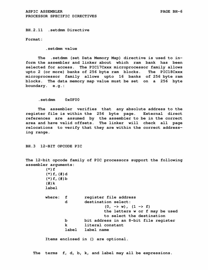
ASPIC ASSEMBLER PAGE BH-6 PROCESSOR SPECIFIC DIRECTIVES
BH.2.11 .setdmm Directive
Format:
.setdmm value
The .setdmm (set Data Memory Map) directive is used to in- form the assembler and linker about which ram bank has been selected for access. The PIC17Cxxx microprocessor family allows upto 2 (or more) banks of 256 byte ram blocks. The PIC18Cxxx microprocessor family allows upto 16 banks of 256 byte ram blocks. The data memory map value must be set on a 256 byte boundary. e.g.:
.setdmm 0x0F00
The assembler verifies that any absolute address to the register file is within the 256 byte page. External direct references are assumed by the assembler to be in the correct area and have valid offsets. The linker will check all page relocations to verify that they are within the correct address- ing range.
BH.3 12-BIT OPCODE PIC
The 12-bit opcode family of PIC processors support the following assembler arguments: (*)f (*)f,(#)d (*)f,(#)b (#)k label where: f register file address d destination select: (0, -> w), (1 -> f) the letters w or f may be used to select the destination b bit address in an 8-bit file register k literal constant label label name Items enclosed in () are optional. The terms f, d, b, k, and label may all be expressions.
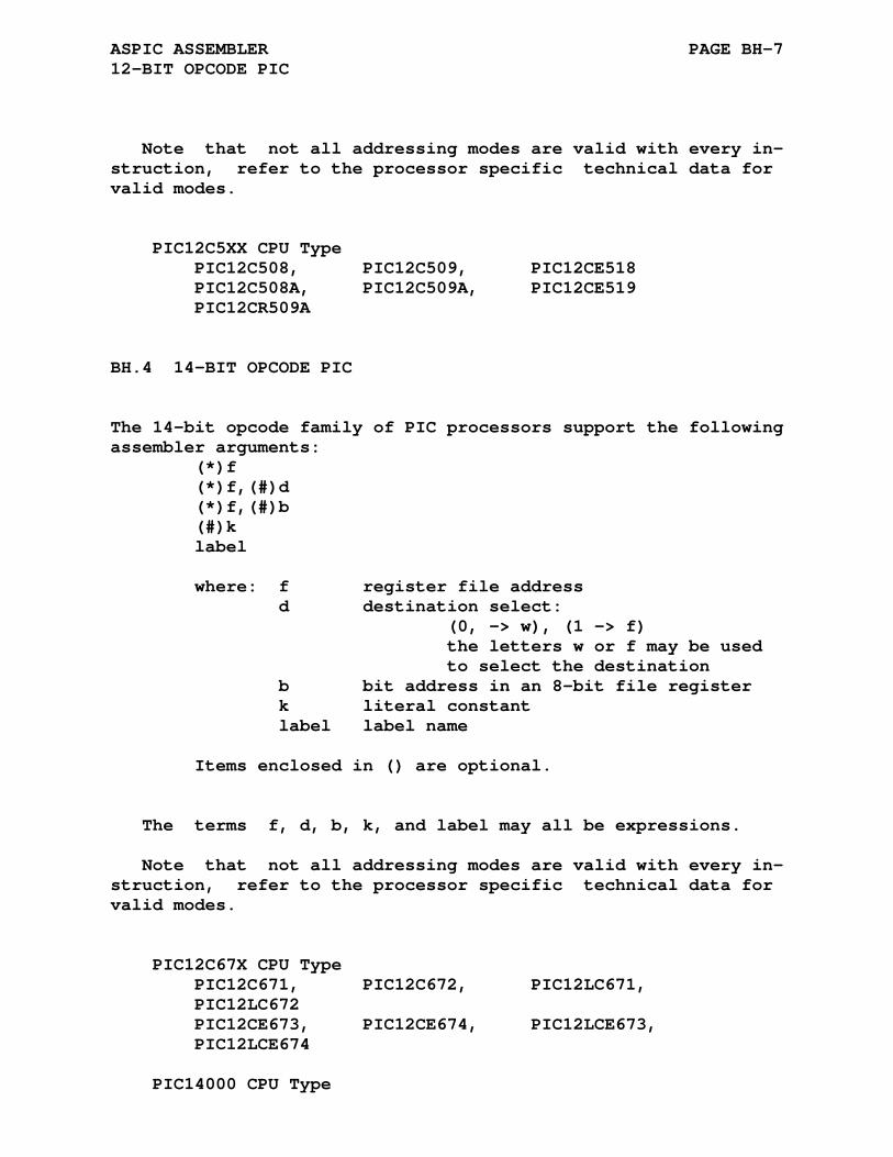
ASPIC ASSEMBLER PAGE BH-7 12-BIT OPCODE PIC
Note that not all addressing modes are valid with every in- struction, refer to the processor specific technical data for valid modes. PIC12C5XX CPU Type PIC12C508, PIC12C509, PIC12CE518 PIC12C508A, PIC12C509A, PIC12CE519 PIC12CR509A
BH.4 14-BIT OPCODE PIC
The 14-bit opcode family of PIC processors support the following assembler arguments: (*)f (*)f,(#)d (*)f,(#)b (#)k label where: f register file address d destination select: (0, -> w), (1 -> f) the letters w or f may be used to select the destination b bit address in an 8-bit file register k literal constant label label name Items enclosed in () are optional. The terms f, d, b, k, and label may all be expressions. Note that not all addressing modes are valid with every in- struction, refer to the processor specific technical data for valid modes. PIC12C67X CPU Type PIC12C671, PIC12C672, PIC12LC671, PIC12LC672 PIC12CE673, PIC12CE674, PIC12LCE673, PIC12LCE674 PIC14000 CPU Type

ASPIC ASSEMBLER PAGE BH-8 14-BIT OPCODE PIC
PIC14000 PIC16C15X CPU Type PIC16C154, PIC16C156, PIC16C158 PIC16CR154, PIC16CR156, PIC16CR158 PIC16C5X CPU Type PIC16C52 PIC16C54, PICC16C54A, PIC16C54B, PIC16C54C PIC16CR54, PIC16CR54A, PIC16C54B, PIC16CR54C PIC16C55, PIC16C55A, PIC16C56, PIC16C56A PIC16CR56A PIC16C57, PIC16CR57A, PIC16C57B, PIC16C57C PIC16C58A, PIC16CR58A, PIC16C58B, PIC16CR58B PIC16C55X CPU Type PIC16C554, PIC16C556, PIC16C558 PIC16C62X, PIC16C64X and, PIC16C66X CPU Types PIC16C620, PIC16C621, PIC16C622 PIC16C642, PIC16C662 PIC16C7XX CPU Type PIC16C71, PIC16C72, PIC16CR72 PIC16C73A, PIC16C74A, PIC16C76, PIC16C77 PIC16C710, PIC16C711, PIC16C715 PIC16C8X CPU Type PIC16F83, PIC16CR83, PIC16F84, PIC16CR84 PIC16HV540 PIC16F627, PIC16F628 PIC16F870, PIC16F871, PIC16F872, PIC16F873 PIC16F874, PIC16F876, PIC16F877 PIC16C9XX CPU Type PIC16C923, PIC16C924

ASPIC ASSEMBLER PAGE BH-9 16-BIT OPCODE PIC
BH.5 16-BIT OPCODE PIC
The 16-bit opcode family of PIC processors support the following assembler arguments: (*)f (*)f,(#)d (*)f,(#)s (*)f,(#)b (*)f,(*)p / (*)p,(*)f (#)t,(*)f (#)t,(#)i,(*)f {#}k label where: f register file address d destination select: (0, -> w), (1 -> f) the letters w or f may be used to select the destination s destination select: (0, -> f and w), (1, -> f) the letters w or f may be used to select the destination t table byte select: (0, -> lower byte) (1, -> upper byte) i table pointer control (0, -> no change) (1, -> post increment) b bit address of an 8-bit file register p peripheral register file address k literal constant label label name Items enclosed in () are optional. The terms f, d, s, t, i, b, p, k, and label may all be expressions. Note that not all addressing modes are valid with every in- struction, refer to the processor specific technical data for valid modes. PIC17CXXX CPU Type PIC17C42, PIC17C42A, PIC17C43, PIC17C44 PIC17C752, PIC17C756, PIC17C756A
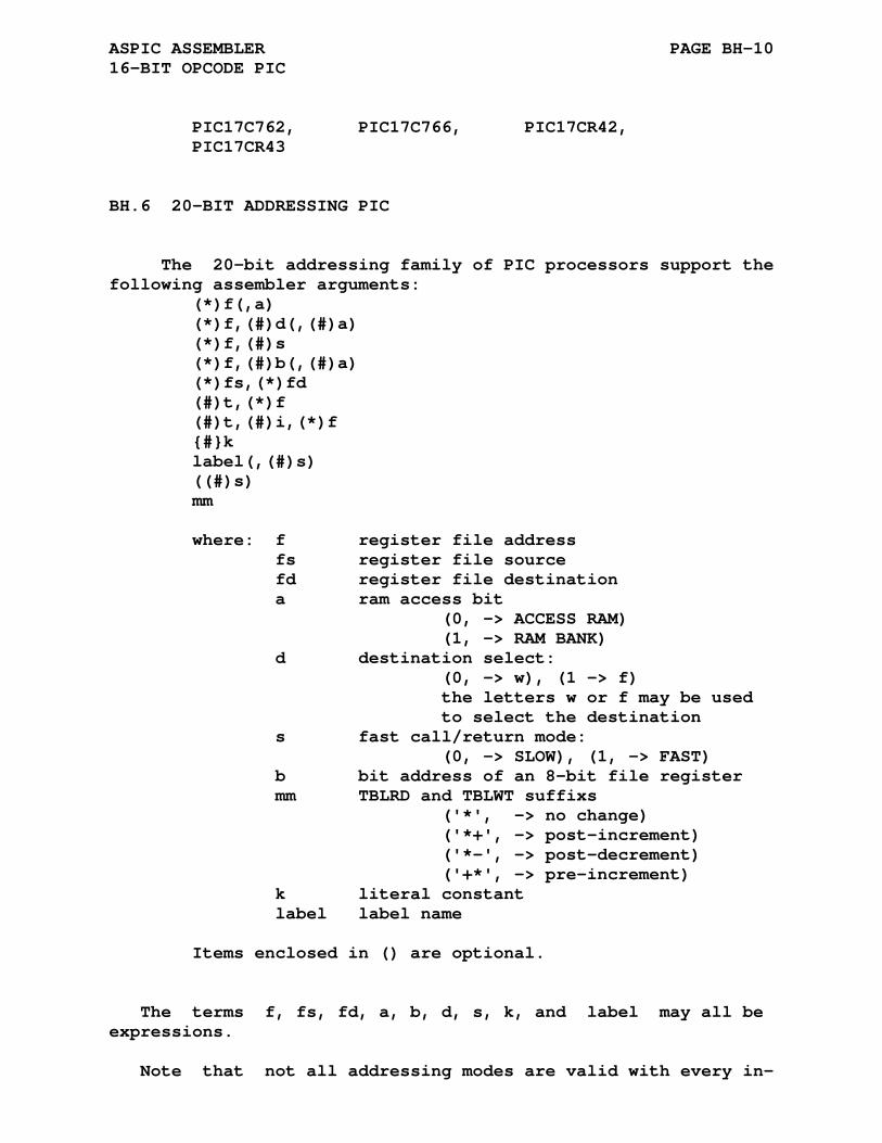
ASPIC ASSEMBLER PAGE BH-10 16-BIT OPCODE PIC
PIC17C762, PIC17C766, PIC17CR42, PIC17CR43
BH.6 20-BIT ADDRESSING PIC
The 20-bit addressing family of PIC processors support the following assembler arguments: (*)f(,a) (*)f,(#)d(,(#)a) (*)f,(#)s (*)f,(#)b(,(#)a) (*)fs,(*)fd (#)t,(*)f (#)t,(#)i,(*)f {#}k label(,(#)s) ((#)s) mm where: f register file address fs register file source fd register file destination a ram access bit (0, -> ACCESS RAM) (1, -> RAM BANK) d destination select: (0, -> w), (1 -> f) the letters w or f may be used to select the destination s fast call/return mode: (0, -> SLOW), (1, -> FAST) b bit address of an 8-bit file register mm TBLRD and TBLWT suffixs ('*', -> no change) ('*+', -> post-increment) ('*-', -> post-decrement) ('+*', -> pre-increment) k literal constant label label name Items enclosed in () are optional. The terms f, fs, fd, a, b, d, s, k, and label may all be expressions. Note that not all addressing modes are valid with every in-
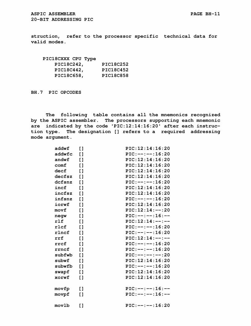
ASPIC ASSEMBLER PAGE BH-11 20-BIT ADDRESSING PIC
struction, refer to the processor specific technical data for valid modes. PIC18CXXX CPU Type PIC18C242, PIC18C252 PIC18C442, PIC18C452 PIC18C658, PIC18C858
BH.7 PIC OPCODES
The following table contains all the mnemonics recognized by the ASPIC assembler. The processors supporting each mnemonic are indicated by the code 'PIC:12:14:16:20' after each instruc- tion type. The designation [] refers to a required addressing mode argument.
addwf [] PIC:12:14:16:20 addwfc [] PIC:--:--:16:20 andwf [] PIC:12:14:16:20 comf [] PIC:12:14:16:20 decf [] PIC:12:14:16:20 decfsz [] PIC:12:14:16:20 dcfsnz [] PIC:--:--:16:20 incf [] PIC:12:14:16:20 incfsz [] PIC:12:14:16:20 infsnz [] PIC:--:--:16:20 iorwf [] PIC:12:14:16:20 movf [] PIC:12:14:--:20 negw [] PIC:--:--:16:-- rlf [] PIC:12:14:--:-- rlcf [] PIC:--:--:16:20 rlncf [] PIC:--:--:16:20 rrf [] PIC:12:14:--:-- rrcf [] PIC:--:--:16:20 rrncf [] PIC:--:--:16:20 subfwb [] PIC:--:--:--:20 subwf [] PIC:12:14:16:20 subwfb [] PIC:--:--:16:20 swapf [] PIC:12:14:16:20 xorwf [] PIC:12:14:16:20 movfp [] PIC:--:--:16:-- movpf [] PIC:--:--:16:-- movlb [] PIC:--:--:16:20

ASPIC ASSEMBLER PAGE BH-12 PIC OPCODES
movlr [] PIC:--:--:16:-- movff [] PIC:--:--:--:20 lfsr [] PIC:--:--:--:20 clrf [] PIC:12:14:16:20 cpfseq [] PIC:--:--:16:20 cpfsgt [] PIC:--:--:16:20 cpfslt [] PIC:--:--:16:20 movwf [] PIC:12:14:16:20 mulwf [] PIC:--:--:16:20 negf [] PIC:--:--:--:20 setf [] PIC:--:--:16:20 tstfsz [] PIC:--:--:16:20 bcf [] PIC:12:14:16:20 bsf [] PIC:12:14:16:20 btfsc [] PIC:12:14:16:20 btfss [] PIC:12:14:16:20 btg [] PIC:--:--:16:20 addlw [] PIC:--:14:16:20 andlw [] PIC:12:14:16:20 iorlw [] PIC:12:14:16:20 movlw [] PIC:12:14:16:20 mullw [] PIC:--:--:16:20 retlw [] PIC:12:14:16:20 sublw [] PIC:--:14:16:20 xorlw [] PIC:12:14:16:20 call [] PIC:12:14:16:20 goto [] PIC:12:14:16:20 lcall [] PIC:--:--:16:-- bc [] PIC:--:--:--:20 bn [] PIC:--:--:--:20 bnc [] PIC:--:--:--:20 bnn [] PIC:--:--:--:20 bnov [] PIC:--:--:--:20 bnc [] PIC:--:--:--:20 bov [] PIC:--:--:--:20 bz [] PIC:--:--:--:20 bra [] PIC:--:--:--:20 rcall [] PIC:--:--:--:20 tablrd [] PIC:--:--:16:-- tablwt [] PIC:--:--:16:--
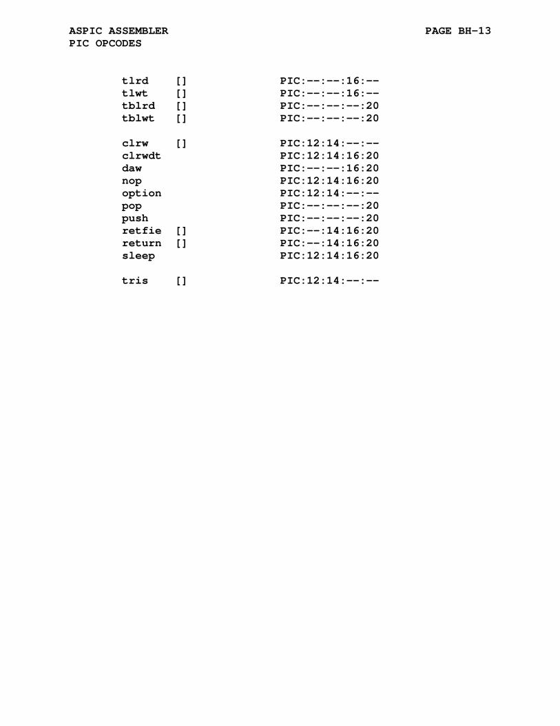
ASPIC ASSEMBLER PAGE BH-13 PIC OPCODES
tlrd [] PIC:--:--:16:-- tlwt [] PIC:--:--:16:-- tblrd [] PIC:--:--:--:20 tblwt [] PIC:--:--:--:20 clrw [] PIC:12:14:--:-- clrwdt PIC:12:14:16:20 daw PIC:--:--:16:20 nop PIC:12:14:16:20 option PIC:12:14:--:-- pop PIC:--:--:--:20 push PIC:--:--:--:20 retfie [] PIC:--:14:16:20 return [] PIC:--:14:16:20 sleep PIC:12:14:16:20 tris [] PIC:12:14:--:--
APPENDIX BI
ASRAB ASSEMBLER
BI.1 ACKNOWLEDGMENT
Thanks to Ulrich Raich and Razaq Ijoduola for their contri- bution of the ASRAB cross assembler.
Ulrich Raich and Razaq Ijoduola PS Division CERN CH-1211 Geneva-23 Ulrich Raich Ulrich dot Raich at cern dot ch
BI.2 PROCESSOR SPECIFIC DIRECTIVES
The ASRAB assembler is a port of the ASZ80 assembler. This assembler can process Z80, HD64180 (Z180), and Rabbit 2000/3000 (default) code. The following processor specific assembler directives specify which processor to target when processing the input assembler files.

ASRAB ASSEMBLER PAGE BI-2 PROCESSOR SPECIFIC DIRECTIVES
BI.2.1 .r2k Directive
Format:
.r2k
The .r2k directive enables processing of the Rabbit 2000/3000 specific mnemonics. Mnemonics not associated with the Rabbit 2000/3000 processor will be flagged with an <o> error. Address- ing modes not supported by the Rabbit 2000/3000 will be flagged with an <a> error. A synonym of .r2k is .r3k. The default as- sembler mode is .r2k.
The .r2k directive also selects the Rabbit 2000/3000 specific cycles count to be output.
BI.2.2 .hd64 Directive
Format:
.hd64
The .hd64 directive enables processing of the HD64180 (Z180) specific mnemonics not included in the Z80 instruction set. Rabbit 2000/3000 mnemonics encountered will be flagged with an <o> error. Addressing modes not supported by the HD64180 (Z180) will be flagged with an <a> error. A synonym of .hd64 is .z180.
The .hd64 directive also selects the HD64180/Z180 specific cycles count to be output.
BI.2.3 .z80 Directive
Format:
.z80
The .z80 directive enables processing of the Z80 specific mnemonics. HD64180 and Rabbit 2000/3000 specific mnemonics will be flagged with an <o> error. Addressing modes not supported by the z80 will be flagged with an <a> error.
The .z80 directive also selects the Z80 specific cycles count to be output.

ASRAB ASSEMBLER PAGE BI-3 PROCESSOR SPECIFIC DIRECTIVES
BI.2.4 The .__.CPU. Variable
The value of the pre-defined symbol '.__.CPU.' corresponds to the selected processor type. The default value is 0 which corresponds to the default processor type. The following table lists the processor types and associated values for the ASRAB assembler:
Processor Type .__.CPU. Value -------------- -------------- .r2k / .r3k 0 .hd64 / .z180 1 .z80 2
The variable '.__.CPU.' is by default defined as local and will not be output to the created .rel file. The assembler com- mand line options -g or -a will not cause the local symbol to be output to the created .rel file.
The assembler .globl directive may be used to change the variable type to global causing its definition to be output to the .rel file. The inclusion of the definition of the variable '.__.CPU.' might be a useful means of validating that seperately assembled files have been compiled for the same processor type. The linker will report an error for variables with multiple non equal definitions.
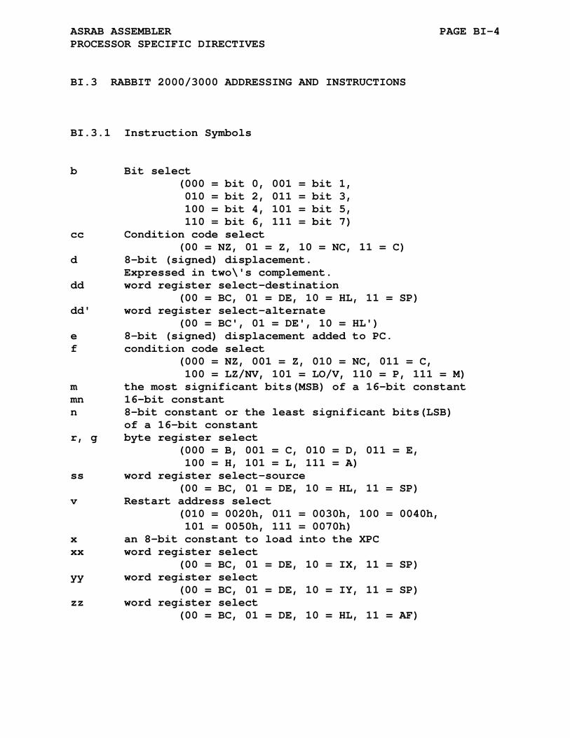
ASRAB ASSEMBLER PAGE BI-4 PROCESSOR SPECIFIC DIRECTIVES
BI.3 RABBIT 2000/3000 ADDRESSING AND INSTRUCTIONS
BI.3.1 Instruction Symbols
b Bit select (000 = bit 0, 001 = bit 1, 010 = bit 2, 011 = bit 3, 100 = bit 4, 101 = bit 5, 110 = bit 6, 111 = bit 7) cc Condition code select (00 = NZ, 01 = Z, 10 = NC, 11 = C) d 8-bit (signed) displacement. Expressed in two\'s complement. dd word register select-destination (00 = BC, 01 = DE, 10 = HL, 11 = SP) dd' word register select-alternate (00 = BC', 01 = DE', 10 = HL') e 8-bit (signed) displacement added to PC. f condition code select (000 = NZ, 001 = Z, 010 = NC, 011 = C, 100 = LZ/NV, 101 = LO/V, 110 = P, 111 = M) m the most significant bits(MSB) of a 16-bit constant mn 16-bit constant n 8-bit constant or the least significant bits(LSB) of a 16-bit constant r, g byte register select (000 = B, 001 = C, 010 = D, 011 = E, 100 = H, 101 = L, 111 = A) ss word register select-source (00 = BC, 01 = DE, 10 = HL, 11 = SP) v Restart address select (010 = 0020h, 011 = 0030h, 100 = 0040h, 101 = 0050h, 111 = 0070h) x an 8-bit constant to load into the XPC xx word register select (00 = BC, 01 = DE, 10 = IX, 11 = SP) yy word register select (00 = BC, 01 = DE, 10 = IY, 11 = SP) zz word register select (00 = BC, 01 = DE, 10 = HL, 11 = AF)
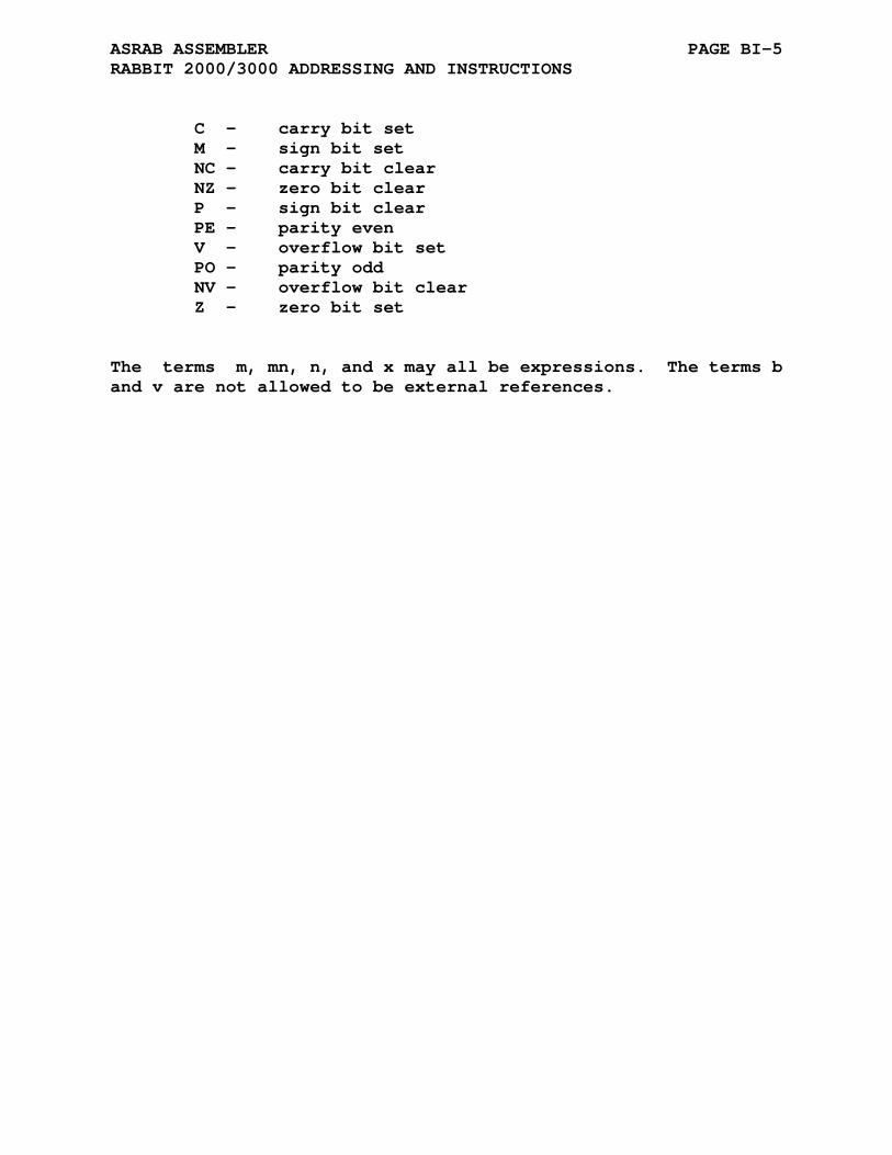
ASRAB ASSEMBLER PAGE BI-5 RABBIT 2000/3000 ADDRESSING AND INSTRUCTIONS
C - carry bit set M - sign bit set NC - carry bit clear NZ - zero bit clear P - sign bit clear PE - parity even V - overflow bit set PO - parity odd NV - overflow bit clear Z - zero bit set
The terms m, mn, n, and x may all be expressions. The terms b and v are not allowed to be external references.
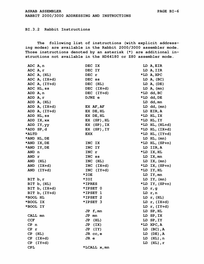
ASRAB ASSEMBLER PAGE BI-6 RABBIT 2000/3000 ADDRESSING AND INSTRUCTIONS
BI.3.2 Rabbit Instructions
The following list of instructions (with explicit address- ing modes) are available in the Rabbit 2000/3000 assembler mode. Those instructions denoted by an asterisk (*) are additional in- structions not available in the HD64180 or Z80 assembler mode.
ADC A,n DEC IX LD A,EIR ADC A,r DEC IY LD A,IIR ADC A,(HL) DEC r *LD A,XPC ADC A,(IX+d) DEC ss LD A,(BC) ADC A,(IY+d) DEC (HL) LD A,(DE) ADC HL,ss DEC (IX+d) LD A,(mn) ADD A,n DEC (IY+d) *LD dd,BC ADD A,r DJNZ e *LD dd,DE ADD A,(HL) LD dd,mn ADD A,(IX+d) EX AF,AF LD dd,(mn) ADD A,(IY+d) EX DE,HL LD EIR,A ADD HL,ss EX DE,HL *LD HL,IX ADD IX,xx EX (SP),HL *LD HL,IY ADD IY,yy EX (SP),IX *LD HL,(HL+d) *ADD SP,d EX (SP),IY *LD HL,(IX+d) *ALTD EXX *LD HL,(IY+d) *AND HL,DE LD HL,(mn) *AND IX,DE INC IX *LD HL,(SP+n) *AND IY,DE INC IY LD IIR,A AND n INC r *LD IX,HL AND r INC ss LD IX,mn AND (HL) INC (HL) LD IX,(mn) AND (IX+d) INC (IX+d) *LD IX,(SP+n) AND (IY+d) INC (IY+d) *LD IY,HL *IOE LD IY,mn BIT b,r *IOI LD IY,(mn) BIT b,(HL) *IPRES *LD IY,(SP+n) BIT b,(IX+d) *IPSET 0 LD r,g BIT b,(IY+d) *IPSET 1 LD r,n *BOOL HL *IPSET 2 LD r,(HL) *BOOL IX *IPSET 3 LD r,(IX+d) *BOOL IY LD r,(IY+d) JP f,mn LD SP,HL CALL mn JP mn LD SP,IX CCF JP (HL) LD SP,IY CP n JP (IX) *LD XPC,A CP r JP (IY) LD (BC),A CP (HL) JR cc,e LD (DE),A CP (IX+d) JR e LD (HL),n CP (IY+d) LD (HL),r CPL *LCALL x,mn
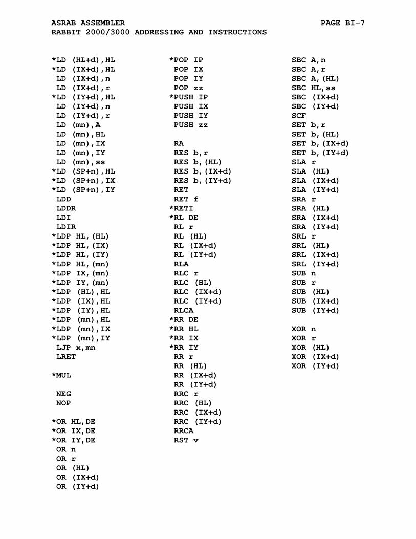
ASRAB ASSEMBLER PAGE BI-7 RABBIT 2000/3000 ADDRESSING AND INSTRUCTIONS
*LD (HL+d),HL *POP IP SBC A,n *LD (IX+d),HL POP IX SBC A,r LD (IX+d),n POP IY SBC A,(HL) LD (IX+d),r POP zz SBC HL,ss *LD (IY+d),HL *PUSH IP SBC (IX+d) LD (IY+d),n PUSH IX SBC (IY+d) LD (IY+d),r PUSH IY SCF LD (mn),A PUSH zz SET b,r LD (mn),HL SET b,(HL) LD (mn),IX RA SET b,(IX+d) LD (mn),IY RES b,r SET b,(IY+d) LD (mn),ss RES b,(HL) SLA r *LD (SP+n),HL RES b,(IX+d) SLA (HL) *LD (SP+n),IX RES b,(IY+d) SLA (IX+d) *LD (SP+n),IY RET SLA (IY+d) LDD RET f SRA r LDDR *RETI SRA (HL) LDI *RL DE SRA (IX+d) LDIR RL r SRA (IY+d) *LDP HL,(HL) RL (HL) SRL r *LDP HL,(IX) RL (IX+d) SRL (HL) *LDP HL,(IY) RL (IY+d) SRL (IX+d) *LDP HL,(mn) RLA SRL (IY+d) *LDP IX,(mn) RLC r SUB n *LDP IY,(mn) RLC (HL) SUB r *LDP (HL),HL RLC (IX+d) SUB (HL) *LDP (IX),HL RLC (IY+d) SUB (IX+d) *LDP (IY),HL RLCA SUB (IY+d) *LDP (mn),HL *RR DE *LDP (mn),IX *RR HL XOR n *LDP (mn),IY *RR IX XOR r LJP x,mn *RR IY XOR (HL) LRET RR r XOR (IX+d) RR (HL) XOR (IY+d) *MUL RR (IX+d) RR (IY+d) NEG RRC r NOP RRC (HL) RRC (IX+d) *OR HL,DE RRC (IY+d) *OR IX,DE RRCA *OR IY,DE RST v OR n OR r OR (HL) OR (IX+d) OR (IY+d)
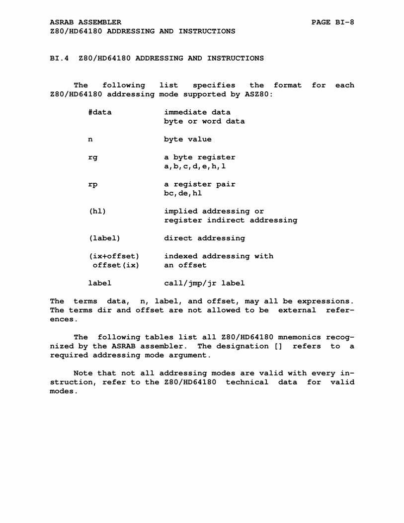
ASRAB ASSEMBLER PAGE BI-8 Z80/HD64180 ADDRESSING AND INSTRUCTIONS
BI.4 Z80/HD64180 ADDRESSING AND INSTRUCTIONS
The following list specifies the format for each Z80/HD64180 addressing mode supported by ASZ80:
#data immediate data byte or word data n byte value rg a byte register a,b,c,d,e,h,l rp a register pair bc,de,hl (hl) implied addressing or register indirect addressing (label) direct addressing (ix+offset) indexed addressing with offset(ix) an offset label call/jmp/jr label
The terms data, n, label, and offset, may all be expressions. The terms dir and offset are not allowed to be external refer- ences.
The following tables list all Z80/HD64180 mnemonics recog- nized by the ASRAB assembler. The designation [] refers to a required addressing mode argument.
Note that not all addressing modes are valid with every in- struction, refer to the Z80/HD64180 technical data for valid modes.
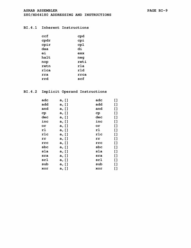
ASRAB ASSEMBLER PAGE BI-9 Z80/HD64180 ADDRESSING AND INSTRUCTIONS
BI.4.1 Inherent Instructions
ccf cpd cpdr cpi cpir cpl daa di ei exx halt neg nop reti retn rla rlca rld rra rrca rrd scf
BI.4.2 Implicit Operand Instructions
adc a,[] adc [] add a,[] add [] and a,[] and [] cp a,[] cp [] dec a,[] dec [] inc a,[] inc [] or a,[] or [] rl a,[] rl [] rlc a,[] rlc [] rr a,[] rr [] rrc a,[] rrc [] sbc a,[] sbc [] sla a,[] sla [] sra a,[] sra [] srl a,[] srl [] sub a,[] sub [] xor a,[] xor []

ASRAB ASSEMBLER PAGE BI-10 Z80/HD64180 ADDRESSING AND INSTRUCTIONS
BI.4.3 Load Instruction
ld rg,[] ld [],rg ld (bc),a ld a,(bc) ld (de),a ld a,(de) ld (label),a ld a,(label) ld (label),rp ld rp,(label) ld i,a ld r,a ld a,i ld a,r ld sp,hl ld sp,ix ld sp,iy ld rp,#data ldd lddr ldi ldir
BI.4.4 Call/Return Instructions
call C,label ret C call M,label ret M call NC,label ret NC call NZ,label ret NZ call P,label ret P call PE,label ret PE call PO,label ret PO call Z,label ret Z call label ret
BI.4.5 Jump and Jump to Subroutine Instructions
jp C,label jp M,label jp NC,label jp NZ,label jp P,label jp PE,label jp PO,label jp Z,label jp (hl) jp (ix) jp (iy) jp label djnz label jr C,label jr NC,label jr NZ,label jr Z,label jr label
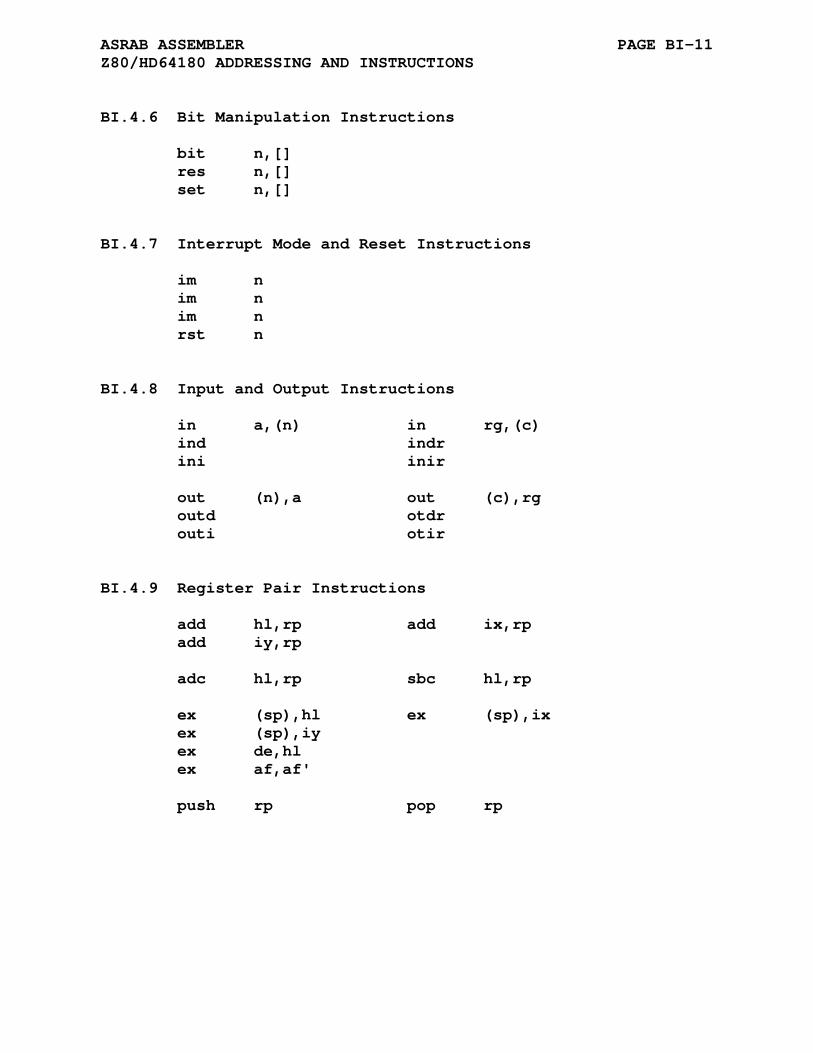
ASRAB ASSEMBLER PAGE BI-11 Z80/HD64180 ADDRESSING AND INSTRUCTIONS
BI.4.6 Bit Manipulation Instructions
bit n,[] res n,[] set n,[]
BI.4.7 Interrupt Mode and Reset Instructions
im n im n im n rst n
BI.4.8 Input and Output Instructions
in a,(n) in rg,(c) ind indr ini inir out (n),a out (c),rg outd otdr outi otir
BI.4.9 Register Pair Instructions
add hl,rp add ix,rp add iy,rp adc hl,rp sbc hl,rp ex (sp),hl ex (sp),ix ex (sp),iy ex de,hl ex af,af' push rp pop rp
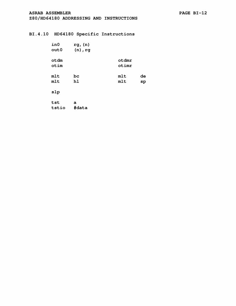
ASRAB ASSEMBLER PAGE BI-12 Z80/HD64180 ADDRESSING AND INSTRUCTIONS
BI.4.10 HD64180 Specific Instructions
in0 rg,(n) out0 (n),rg otdm otdmr otim otimr mlt bc mlt de mlt hl mlt sp slp tst a tstio #data

APPENDIX BJ
ASSCMP ASSEMBLER
BJ.1 SC/MP REGISTER SET
The following is a list of the SC/MP registers used by ASSCMP:
p0,pc - 16-bit program counter p1,p2,p3 - 16-bit pointer registers
BJ.2 SC/MP ADDRESSING MODES
The general addressing modes are normally described in the form @DISP(X) which correspond to these specific modes:
DISP a PC relative address DISP(X) a DISPlacement from a pointer register @DISP(X) An auto-increment DISPlacement from a pointer register
The ASSCMP assembler also allows the ( and ) designators to be replaced by the [ and ] designators.
The ASSCMP assembler also allows several shorthand nota- tions for the addressing modes as shown here:
(X) ==>> 0(X) @(X) ==>> @0(X) @DISP ==>> @DISP(PC)
The xpal, xpah, and xppc instructions require only a pointer register - p0, p1, p2, p3, or pc.
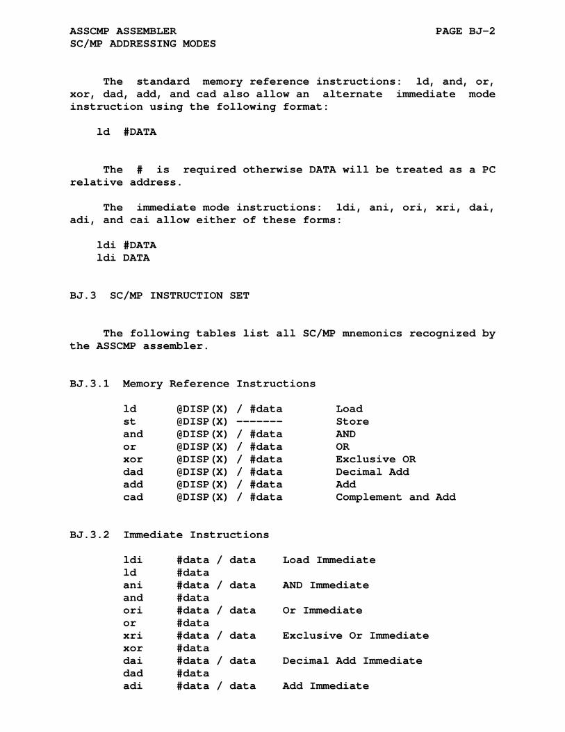
ASSCMP ASSEMBLER PAGE BJ-2 SC/MP ADDRESSING MODES
The standard memory reference instructions: ld, and, or, xor, dad, add, and cad also allow an alternate immediate mode instruction using the following format:
ld #DATA
The # is required otherwise DATA will be treated as a PC relative address.
The immediate mode instructions: ldi, ani, ori, xri, dai, adi, and cai allow either of these forms:
ldi #DATA ldi DATA
BJ.3 SC/MP INSTRUCTION SET
The following tables list all SC/MP mnemonics recognized by the ASSCMP assembler.
BJ.3.1 Memory Reference Instructions
ld @DISP(X) / #data Load st @DISP(X) ------- Store and @DISP(X) / #data AND or @DISP(X) / #data OR xor @DISP(X) / #data Exclusive OR dad @DISP(X) / #data Decimal Add add @DISP(X) / #data Add cad @DISP(X) / #data Complement and Add
BJ.3.2 Immediate Instructions
ldi #data / data Load Immediate ld #data ani #data / data AND Immediate and #data ori #data / data Or Immediate or #data xri #data / data Exclusive Or Immediate xor #data dai #data / data Decimal Add Immediate dad #data adi #data / data Add Immediate
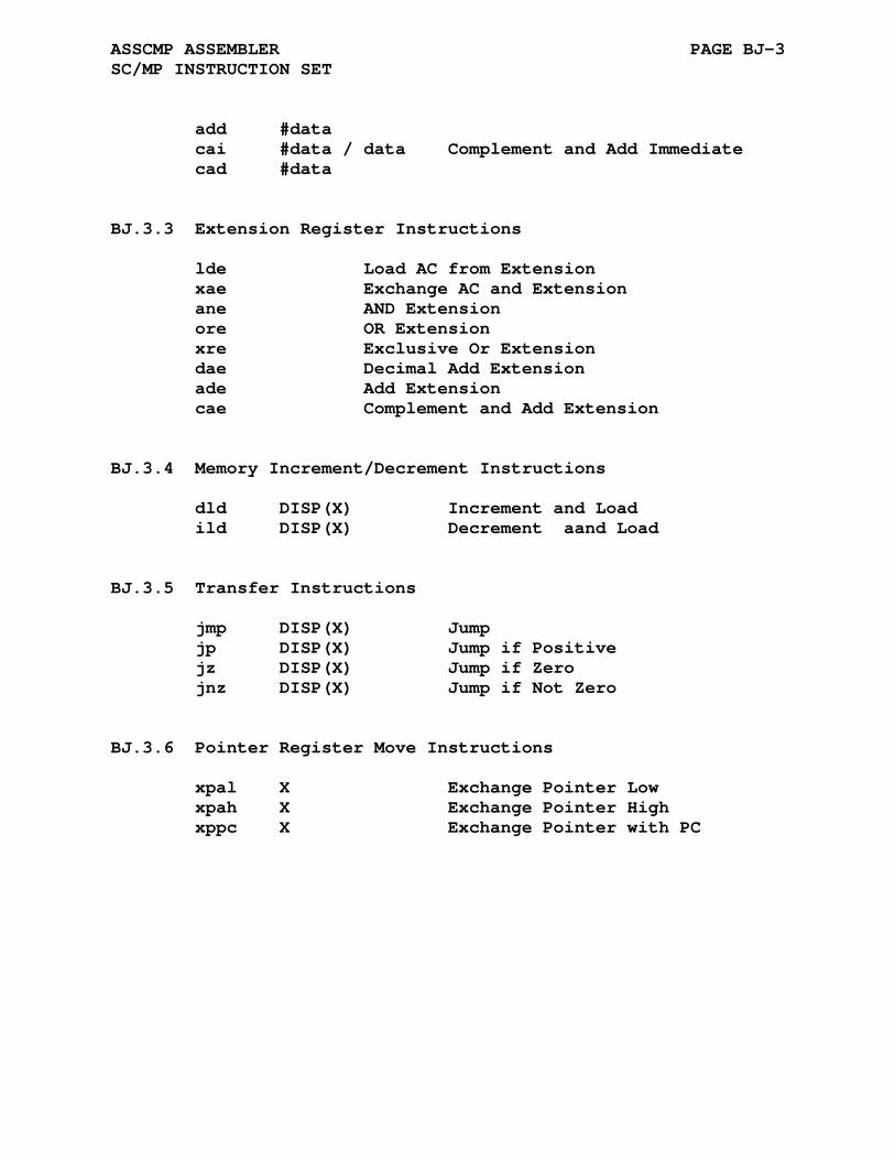
ASSCMP ASSEMBLER PAGE BJ-3 SC/MP INSTRUCTION SET
add #data cai #data / data Complement and Add Immediate cad #data
BJ.3.3 Extension Register Instructions
lde Load AC from Extension xae Exchange AC and Extension ane AND Extension ore OR Extension xre Exclusive Or Extension dae Decimal Add Extension ade Add Extension cae Complement and Add Extension
BJ.3.4 Memory Increment/Decrement Instructions
dld DISP(X) Increment and Load ild DISP(X) Decrement aand Load
BJ.3.5 Transfer Instructions
jmp DISP(X) Jump jp DISP(X) Jump if Positive jz DISP(X) Jump if Zero jnz DISP(X) Jump if Not Zero
BJ.3.6 Pointer Register Move Instructions
xpal X Exchange Pointer Low xpah X Exchange Pointer High xppc X Exchange Pointer with PC
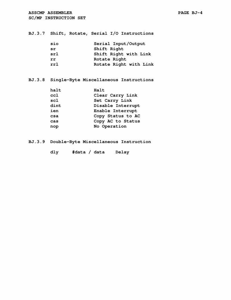
ASSCMP ASSEMBLER PAGE BJ-4 SC/MP INSTRUCTION SET
BJ.3.7 Shift, Rotate, Serial I/O Instructions
sio Serial Input/Output sr Shift Right srl Shift Right with Link rr Rotate Right rrl Rotate Right with Link
BJ.3.8 Single-Byte Miscellaneous Instructions
halt Halt ccl Clear Carry Link scl Set Carry Link dint Disable Interrupt ien Enable Interrupt csa Copy Status to AC cas Copy AC to Status nop No Operation
BJ.3.9 Double-Byte Miscellaneous Instruction
dly #data / data Delay
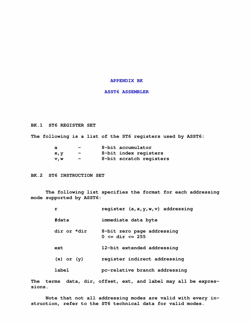
APPENDIX BK
ASST6 ASSEMBLER
BK.1 ST6 REGISTER SET
The following is a list of the ST6 registers used by ASST6:
a - 8-bit accumulator x,y - 8-bit index registers v,w - 8-bit scratch registers
BK.2 ST6 INSTRUCTION SET
The following list specifies the format for each addressing mode supported by ASST6:
r register (a,x,y,w,v) addressing #data immediate data byte dir or *dir 8-bit zero page addressing 0 <= dir <= 255 ext 12-bit extended addressing (x) or (y) register indirect addressing label pc-relative branch addressing
The terms data, dir, offset, ext, and label may all be expres- sions.
Note that not all addressing modes are valid with every in- struction, refer to the ST6 technical data for valid modes.
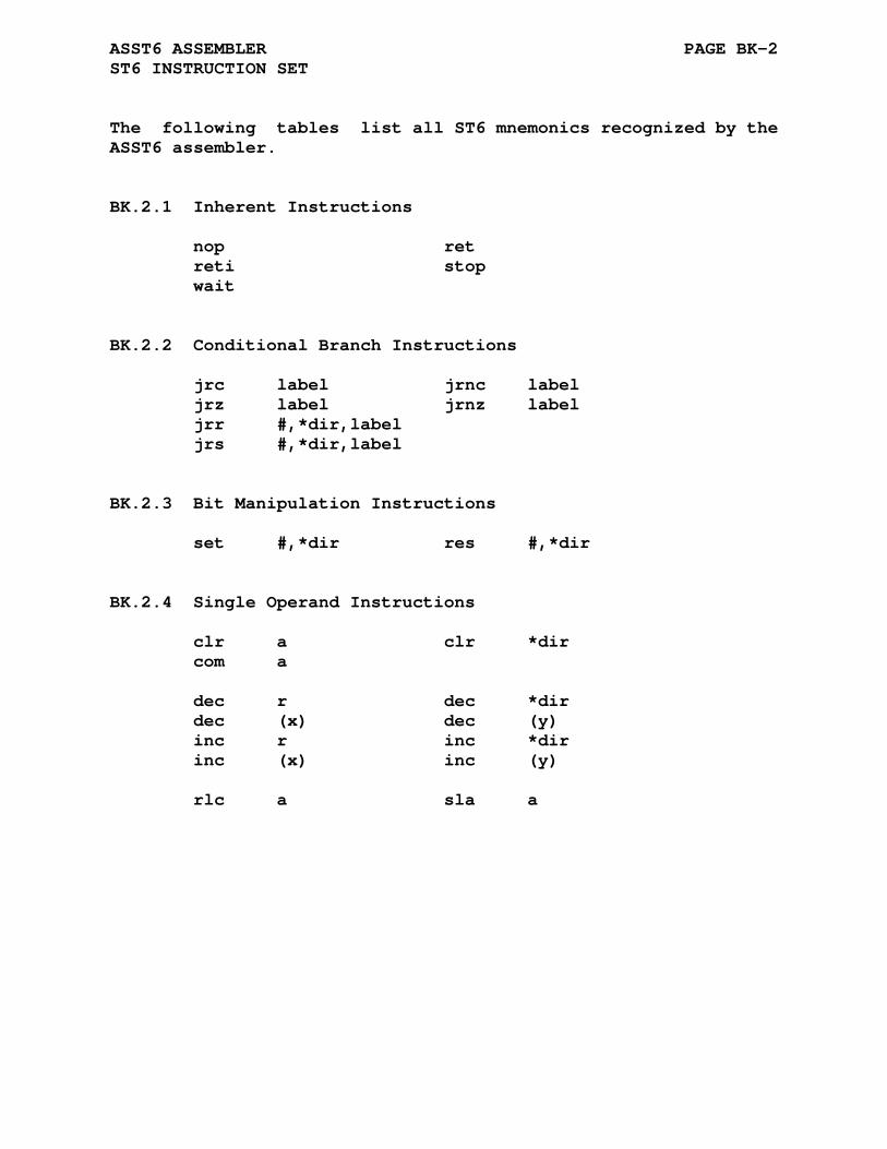
ASST6 ASSEMBLER PAGE BK-2 ST6 INSTRUCTION SET
The following tables list all ST6 mnemonics recognized by the ASST6 assembler.
BK.2.1 Inherent Instructions
nop ret reti stop wait
BK.2.2 Conditional Branch Instructions
jrc label jrnc label jrz label jrnz label jrr #,*dir,label jrs #,*dir,label
BK.2.3 Bit Manipulation Instructions
set #,*dir res #,*dir
BK.2.4 Single Operand Instructions
clr a clr *dir com a dec r dec *dir dec (x) dec (y) inc r inc *dir inc (x) inc (y) rlc a sla a

ASST6 ASSEMBLER PAGE BK-3 ST6 INSTRUCTION SET
BK.2.5 Double Operand Instructions
add a,(x) add a,(y) add a,*dir addi a,# and a,(x) and a,(y) and a,*dir andi a,# cp a,(x) cp a,(y) cp a,*dir cpi a,# sub a,(x) sub a,(y) sub a,*dir subi a,#
BK.2.6 Call to Subroutine and Jump Instructions
call ext jmp ext
BK.2.7 Load and Store Instructions
ld a,x ld a,y ld a,v ld a,w ld x,a ld y,a ld v,a ld w,a ld a,*dir ld *dir,a ld a,(x) ld a,(y) ld (x),a ld (y),a ldi a,# ld *dir,#
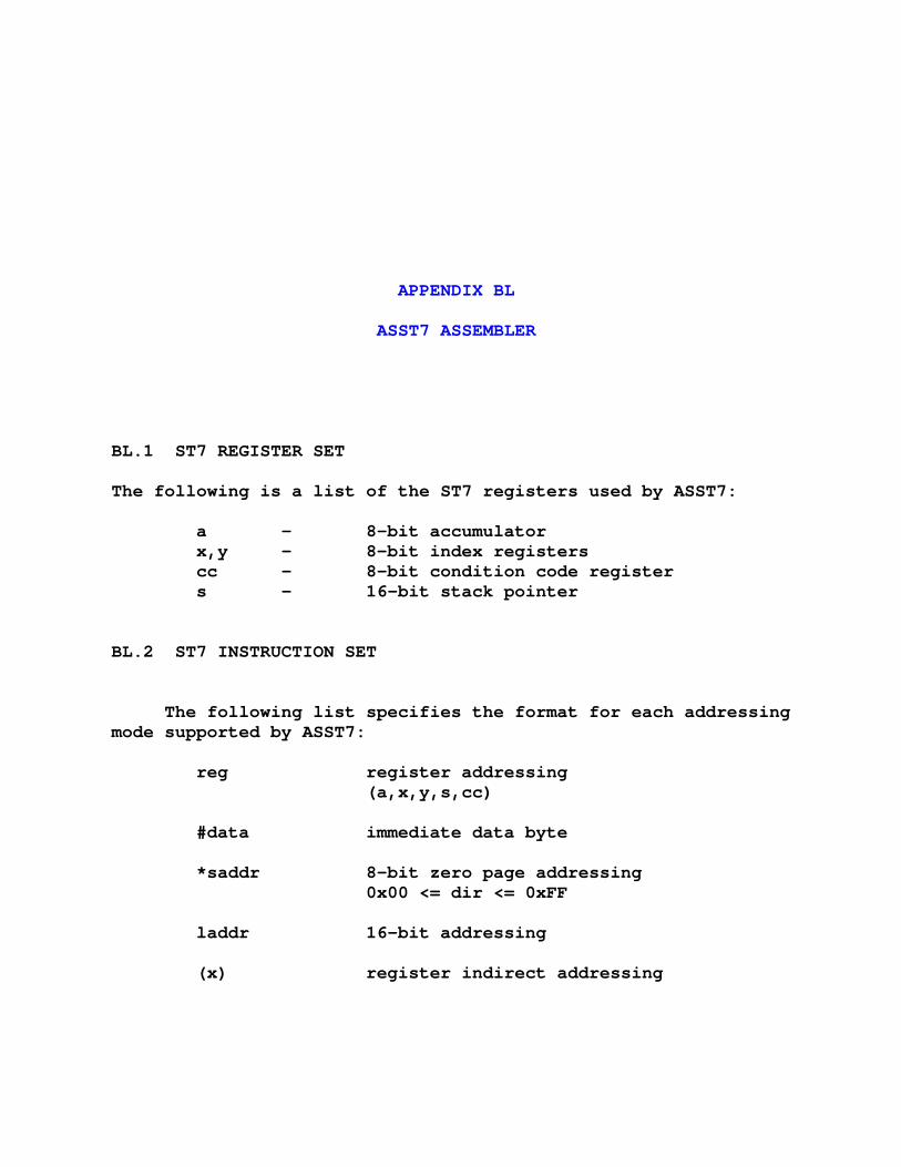
APPENDIX BL
ASST7 ASSEMBLER
BL.1 ST7 REGISTER SET
The following is a list of the ST7 registers used by ASST7:
a - 8-bit accumulator x,y - 8-bit index registers cc - 8-bit condition code register s - 16-bit stack pointer
BL.2 ST7 INSTRUCTION SET
The following list specifies the format for each addressing mode supported by ASST7:
reg register addressing (a,x,y,s,cc) #data immediate data byte *saddr 8-bit zero page addressing 0x00 <= dir <= 0xFF laddr 16-bit addressing (x) register indirect addressing

ASST7 ASSEMBLER PAGE BL-2 ST7 INSTRUCTION SET
(*sofst,r) short indexed (r = x,y) (sofst,r).b (lofst,r).w long indexed (r = x,y) (ofst,r) if ofst is relocatable or an external value then the (lofst,r).w mode is selected by default else (ofst,r) if ofst is a locally defined constant then the (sofst,r).b mode is selected when 0x00 <= ofst <= 0xFF else the (lofst,r).w mode is selected Instructions supporting only a single form will use the appropriate form but will report an error. [*saddr] short indirect [saddr].b [laddr].w long indexed [addr] if addr is relocatable or an external value then the [laddr].w mode is selected by default else [addr] if addr is a locally defined constant then the [saddr].b mode is selected when 0x00 <= addr <= 0xFF else the [laddr].w mode is selected Instructions supporting only a single form will use the appropriate form but will report an error.
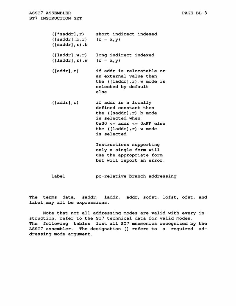
ASST7 ASSEMBLER PAGE BL-3 ST7 INSTRUCTION SET
([*saddr],r) short indirect indexed ([saddr].b,r) (r = x,y) ([saddr],r).b ([laddr].w,r) long indirect indexed ([laddr],r).w (r = x,y) ([addr],r) if addr is relocatable or an external value then the ([laddr],r).w mode is selected by default else ([addr],r) if addr is a locally defined constant then the ([saddr],r).b mode is selected when 0x00 <= addr <= 0xFF else the ([laddr],r).w mode is selected Instructions supporting only a single form will use the appropriate form but will report an error. label pc-relative branch addressing
The terms data, saddr, laddr, addr, sofst, lofst, ofst, and label may all be expressions.
Note that not all addressing modes are valid with every in- struction, refer to the ST7 technical data for valid modes. The following tables list all ST7 mnemonics recognized by the ASST7 assembler. The designation [] refers to a required ad- dressing mode argument.
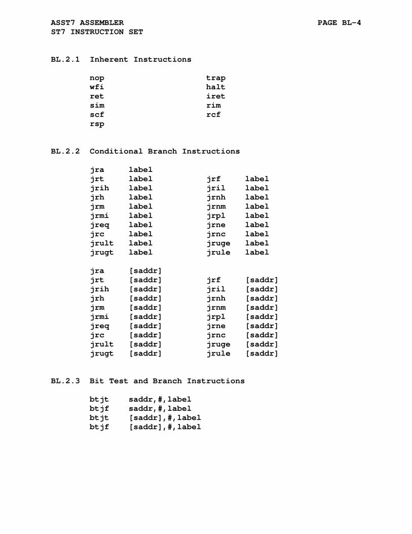
ASST7 ASSEMBLER PAGE BL-4 ST7 INSTRUCTION SET
BL.2.1 Inherent Instructions
nop trap wfi halt ret iret sim rim scf rcf rsp
BL.2.2 Conditional Branch Instructions
jra label jrt label jrf label jrih label jril label jrh label jrnh label jrm label jrnm label jrmi label jrpl label jreq label jrne label jrc label jrnc label jrult label jruge label jrugt label jrule label jra [saddr] jrt [saddr] jrf [saddr] jrih [saddr] jril [saddr] jrh [saddr] jrnh [saddr] jrm [saddr] jrnm [saddr] jrmi [saddr] jrpl [saddr] jreq [saddr] jrne [saddr] jrc [saddr] jrnc [saddr] jrult [saddr] jruge [saddr] jrugt [saddr] jrule [saddr]
BL.2.3 Bit Test and Branch Instructions
btjt saddr,#,label btjf saddr,#,label btjt [saddr],#,label btjf [saddr],#,label

ASST7 ASSEMBLER PAGE BL-5 ST7 INSTRUCTION SET
BL.2.4 Bit Manipulation Instructions
bset saddr,# bres saddr,# bset [saddr],# bres [saddr],#
BL.2.5 Single Operand Instructions
neg [] cpl [] srl [] rrc [] sra [] rlc [] sll [] sla [] dec [] inc [] tnz [] swap [] clr [] pop reg push reg
BL.2.6 Double Operand Instructions
add a,[] adc a,[] and a,[] bcp a,[] or a,[] sbc a,[] sub a,[] xor a,[] mul x,a mul y,a cp reg,[] ld [],[]
BL.2.7 Call to Subroutine and Jump Instructions
call [] jp [] callr label callr [saddr]

APPENDIX BM
ASST8 ASSEMBLER
BM.1 ST8 REGISTER SET
The following is a list of the ST8 registers used by ASST8:
a - 8-bit accumulator xl,yl - LSB of index registers xh,yh - MSB of index registers x,y - 16-Bit index registers sp - 16-bit stack pointer cc - 8-bit condition code register
BM.2 ST8 INSTRUCTION SET
The following list specifies the format for each addressing mode supported by ASST8:
reg register addressing (a,x,xl,xh,y,yl,yh,sp,cc) #data immediate data *saddr 8-bit zero page addressing 0x00 <= saddr <= 0xFF laddr 16-bit addressing 0x0000 <= laddr <= 0xFFFF eaddr 24-bit addressing 0x000000 <= eaddr <= 0xFFFFFF (x) register indirect addressing
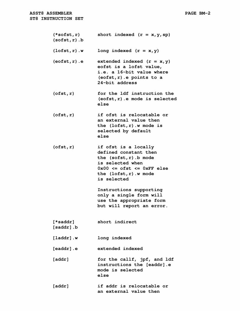
ASST8 ASSEMBLER PAGE BM-2 ST8 INSTRUCTION SET
(*sofst,r) short indexed (r = x,y,sp) (sofst,r).b (lofst,r).w long indexed (r = x,y) (eofst,r).e extended indexed (r = x,y) eofst is a lofst value, i.e. a 16-bit value where (eofst,r).e points to a 24-bit address (ofst,r) for the ldf instruction the (eofst,r).e mode is selected else (ofst,r) if ofst is relocatable or an external value then the (lofst,r).w mode is selected by default else (ofst,r) if ofst is a locally defined constant then the (sofst,r).b mode is selected when 0x00 <= ofst <= 0xFF else the (lofst,r).w mode is selected Instructions supporting only a single form will use the appropriate form but will report an error. [*saddr] short indirect [saddr].b [laddr].w long indexed [eaddr].e extended indexed [addr] for the callf, jpf, and ldf instructions the [eaddr].e mode is selected else [addr] if addr is relocatable or an external value then
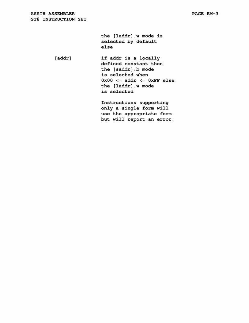
ASST8 ASSEMBLER PAGE BM-3 ST8 INSTRUCTION SET
the [laddr].w mode is selected by default else [addr] if addr is a locally defined constant then the [saddr].b mode is selected when 0x00 <= addr <= 0xFF else the [laddr].w mode is selected Instructions supporting only a single form will use the appropriate form but will report an error.
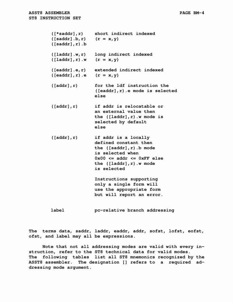
ASST8 ASSEMBLER PAGE BM-4 ST8 INSTRUCTION SET
([*saddr],r) short indirect indexed ([saddr].b,r) (r = x,y) ([saddr],r).b ([laddr].w,r) long indirect indexed ([laddr],r).w (r = x,y) ([eaddr].e,r) extended indirect indexed ([eaddr],r).e (r = x,y) ([addr],r) for the ldf instruction the ([eaddr],r).e mode is selected else ([addr],r) if addr is relocatable or an external value then the ([laddr],r).w mode is selected by default else ([addr],r) if addr is a locally defined constant then the ([saddr],r).b mode is selected when 0x00 <= addr <= 0xFF else the ([laddr],r).w mode is selected Instructions supporting only a single form will use the appropriate form but will report an error. label pc-relative branch addressing
The terms data, saddr, laddr, eaddr, addr, sofst, lofst, eofst, ofst, and label may all be expressions.
Note that not all addressing modes are valid with every in- struction, refer to the ST8 technical data for valid modes. The following tables list all ST8 mnemonics recognized by the ASST8 assembler. The designation [] refers to a required ad- dressing mode argument.

ASST8 ASSEMBLER PAGE BM-5 ST8 INSTRUCTION SET
BM.2.1 Inherent Instructions
nop trap wfi wfi halt ret retf iret sim rim scf rcf rvf ccf
BM.2.2 Conditional Branch Instructions
jra label jrt label jrf label jrugt label jrule label jruge label jrult label jrnc label jrc label jrne label jreq label jrnv label jrv label jrpl label jrmi label jrsgt label jrsle label jrsge label jrslt label jrnh label jrh label jrnm label jrm label jril label jrih label
BM.2.3 Bit Test and Branch Instructions
btjt laddr,#,label btjf laddr,#,label
BM.2.4 Bit Manipulation Instructions
bccm laddr,# bcpl laddr,# bset laddr,# bres laddr,#
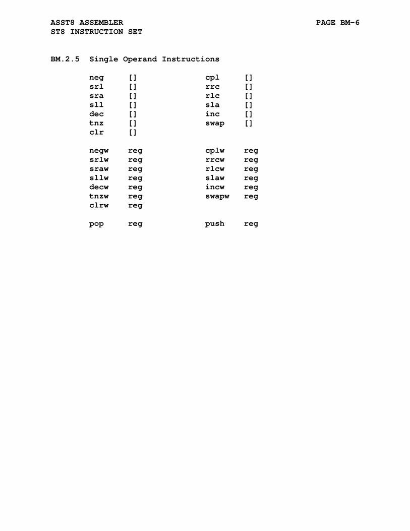
ASST8 ASSEMBLER PAGE BM-6 ST8 INSTRUCTION SET
BM.2.5 Single Operand Instructions
neg [] cpl [] srl [] rrc [] sra [] rlc [] sll [] sla [] dec [] inc [] tnz [] swap [] clr [] negw reg cplw reg srlw reg rrcw reg sraw reg rlcw reg sllw reg slaw reg decw reg incw reg tnzw reg swapw reg clrw reg pop reg push reg

ASST8 ASSEMBLER PAGE BM-7 ST8 INSTRUCTION SET
BM.2.6 Double Operand Instructions
add a,[] adc a,[] and a,[] bcp a,[] cp a,[] or a,[] sbc a,[] sub a,[] xor a,[] add sp,# sub sp,# addw reg,[] subw reg,[] cpw reg,[] mul x,a mul y,a div x,a div y,a divw x,y exg a,reg exg a,laddr exgw x,y rrwa x,a rrwa y,a rlwa x,a rlwa y,a ld [],[] ldf a,[] ldf [],a ldw reg,[] ldw [],reg mov saddr,saddr mov laddr,laddr mov laddr,#
BM.2.7 Call to Subroutine and Jump Instructions
call [] jp [] callf eaddr callf [eaddr].e jpf eaddr jpf [eaddr].e callr label
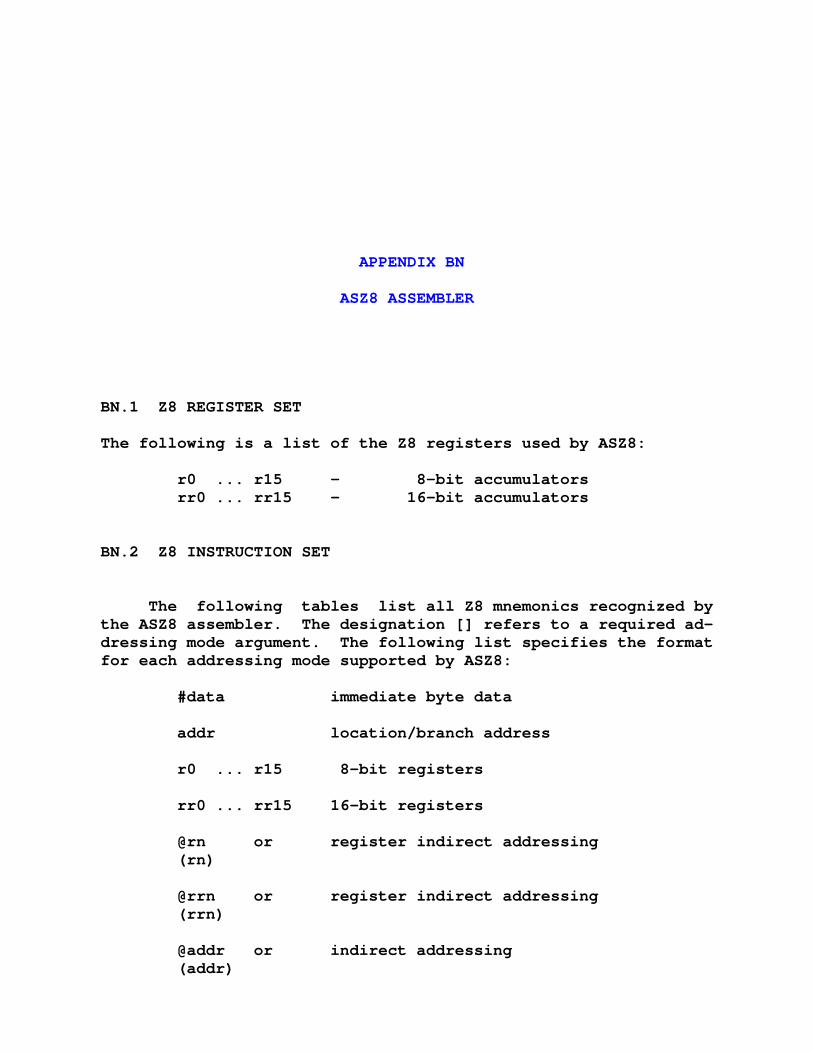
APPENDIX BN
ASZ8 ASSEMBLER
BN.1 Z8 REGISTER SET
The following is a list of the Z8 registers used by ASZ8:
r0 ... r15 - 8-bit accumulators rr0 ... rr15 - 16-bit accumulators
BN.2 Z8 INSTRUCTION SET
The following tables list all Z8 mnemonics recognized by the ASZ8 assembler. The designation [] refers to a required ad- dressing mode argument. The following list specifies the format for each addressing mode supported by ASZ8:
#data immediate byte data addr location/branch address r0 ... r15 8-bit registers rr0 ... rr15 16-bit registers @rn or register indirect addressing (rn) @rrn or register indirect addressing (rrn) @addr or indirect addressing (addr)
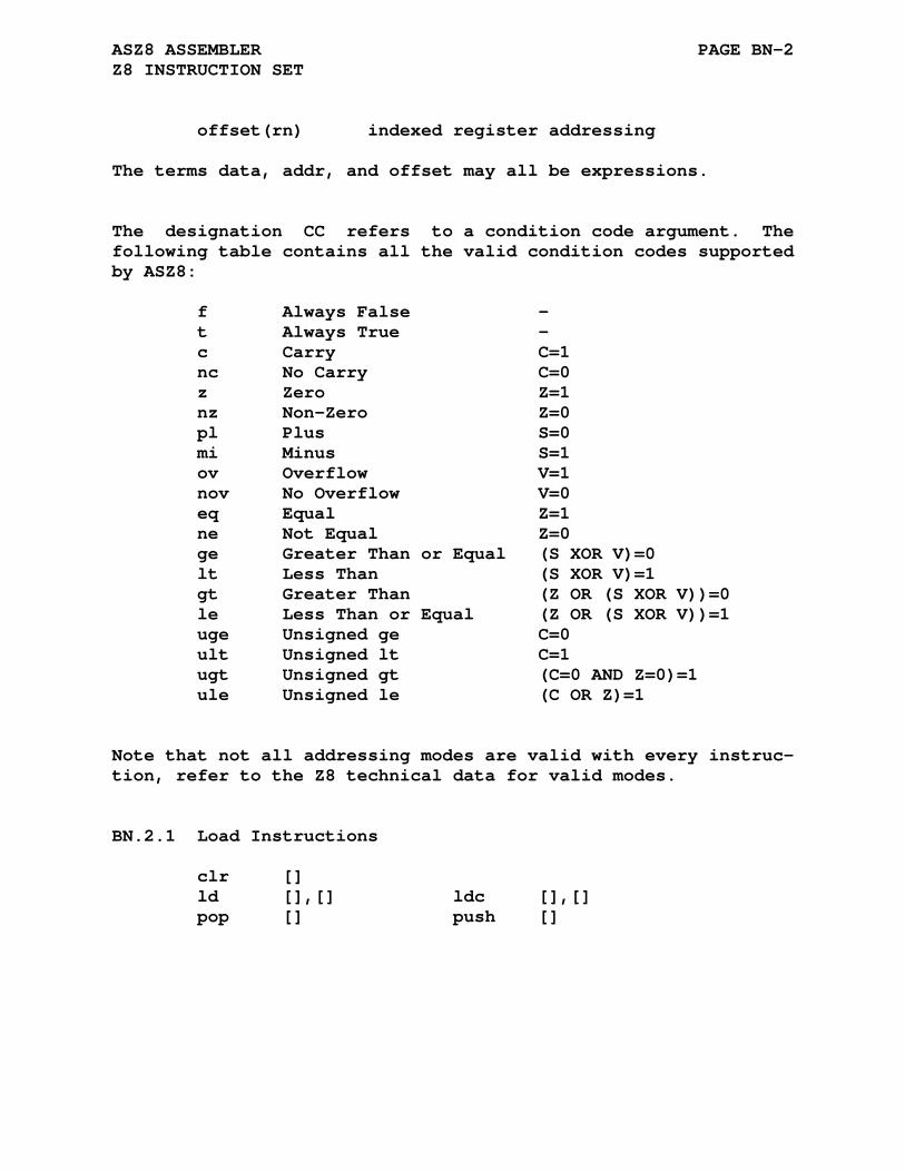
ASZ8 ASSEMBLER PAGE BN-2 Z8 INSTRUCTION SET
offset(rn) indexed register addressing
The terms data, addr, and offset may all be expressions.
The designation CC refers to a condition code argument. The following table contains all the valid condition codes supported by ASZ8:
f Always False - t Always True - c Carry C=1 nc No Carry C=0 z Zero Z=1 nz Non-Zero Z=0 pl Plus S=0 mi Minus S=1 ov Overflow V=1 nov No Overflow V=0 eq Equal Z=1 ne Not Equal Z=0 ge Greater Than or Equal (S XOR V)=0 lt Less Than (S XOR V)=1 gt Greater Than (Z OR (S XOR V))=0 le Less Than or Equal (Z OR (S XOR V))=1 uge Unsigned ge C=0 ult Unsigned lt C=1 ugt Unsigned gt (C=0 AND Z=0)=1 ule Unsigned le (C OR Z)=1
Note that not all addressing modes are valid with every instruc- tion, refer to the Z8 technical data for valid modes.
BN.2.1 Load Instructions
clr [] ld [],[] ldc [],[] pop [] push []
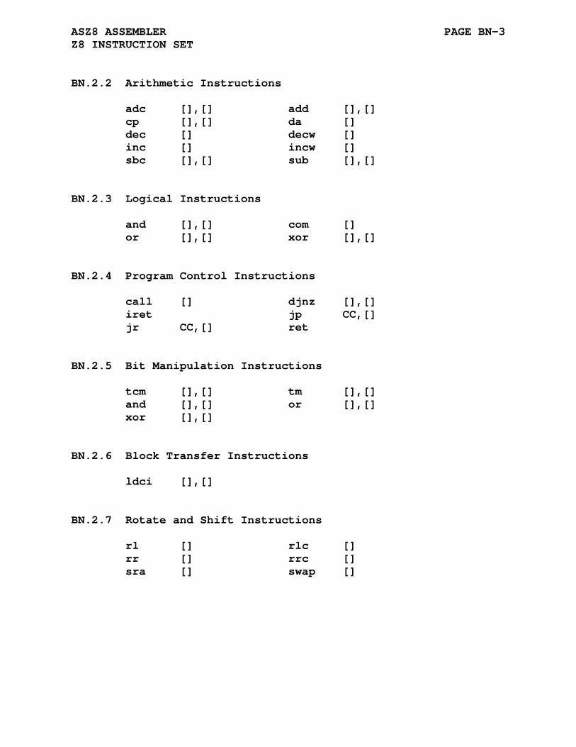
ASZ8 ASSEMBLER PAGE BN-3 Z8 INSTRUCTION SET
BN.2.2 Arithmetic Instructions
adc [],[] add [],[] cp [],[] da [] dec [] decw [] inc [] incw [] sbc [],[] sub [],[]
BN.2.3 Logical Instructions
and [],[] com [] or [],[] xor [],[]
BN.2.4 Program Control Instructions
call [] djnz [],[] iret jp CC,[] jr CC,[] ret
BN.2.5 Bit Manipulation Instructions
tcm [],[] tm [],[] and [],[] or [],[] xor [],[]
BN.2.6 Block Transfer Instructions
ldci [],[]
BN.2.7 Rotate and Shift Instructions
rl [] rlc [] rr [] rrc [] sra [] swap []
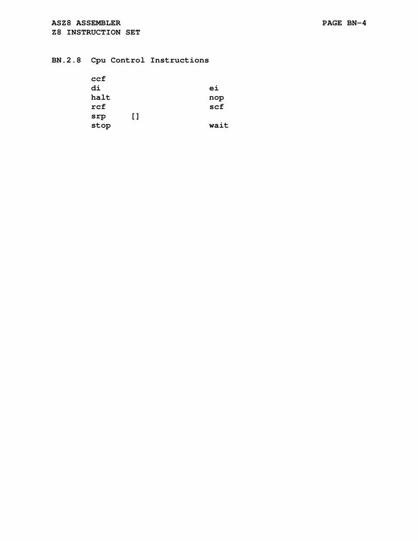
ASZ8 ASSEMBLER PAGE BN-4 Z8 INSTRUCTION SET
BN.2.8 Cpu Control Instructions
ccf di ei halt nop rcf scf srp [] stop wait

APPENDIX BO
ASZ80 ASSEMBLER
BO.1 .z80 DIRECTIVE
Format:
.z80
The .z80 directive enables processing of only the z80 specific mnemonics. HD64180/Z180 mnemonics encountered without the .hd64 directive will be flagged with an <o> error.
The .z80 directive also selects the Z80 specific cycles count to be output.
BO.2 .hd64 DIRECTIVE
Format:
.hd64
The .hd64 directive enables processing of the HD64180/Z180 specific mnemonics not included in the Z80 instruction set. HD64180/Z180 mnemonics encountered without the .hd64 directive will be flagged with an <o> error. A synonym of .hd64 is .z180.
The .hd64 directive also selects the HD64180/Z180 specific cycles count to be output.
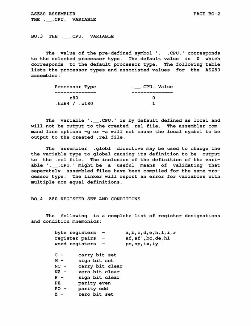
ASZ80 ASSEMBLER PAGE BO-2 THE .__.CPU. VARIABLE
BO.3 THE .__.CPU. VARIABLE
The value of the pre-defined symbol '.__.CPU.' corresponds to the selected processor type. The default value is 0 which corresponds to the default processor type. The following table lists the processor types and associated values for the ASZ80 assembler:
Processor Type .__.CPU. Value -------------- -------------- .z80 0 .hd64 / .z180 1
The variable '.__.CPU.' is by default defined as local and will not be output to the created .rel file. The assembler com- mand line options -g or -a will not cause the local symbol to be output to the created .rel file.
The assembler .globl directive may be used to change the the variable type to global causing its definition to be output to the .rel file. The inclusion of the definition of the vari- able '.__.CPU.' might be a useful means of validating that seperately assembled files have been compiled for the same pro- cessor type. The linker will report an error for variables with multiple non equal definitions.
BO.4 Z80 REGISTER SET AND CONDITIONS
The following is a complete list of register designations and condition mnemonics:
byte registers - a,b,c,d,e,h,l,i,r register pairs - af,af',bc,de,hl word registers - pc,sp,ix,iy C - carry bit set M - sign bit set NC - carry bit clear NZ - zero bit clear P - sign bit clear PE - parity even PO - parity odd Z - zero bit set
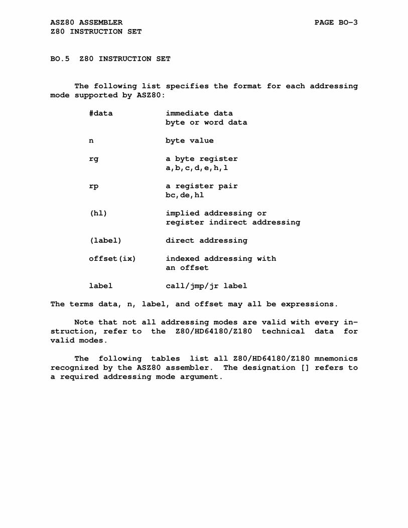
ASZ80 ASSEMBLER PAGE BO-3 Z80 INSTRUCTION SET
BO.5 Z80 INSTRUCTION SET
The following list specifies the format for each addressing mode supported by ASZ80:
#data immediate data byte or word data n byte value rg a byte register a,b,c,d,e,h,l rp a register pair bc,de,hl (hl) implied addressing or register indirect addressing (label) direct addressing offset(ix) indexed addressing with an offset label call/jmp/jr label
The terms data, n, label, and offset may all be expressions.
Note that not all addressing modes are valid with every in- struction, refer to the Z80/HD64180/Z180 technical data for valid modes.
The following tables list all Z80/HD64180/Z180 mnemonics recognized by the ASZ80 assembler. The designation [] refers to a required addressing mode argument.
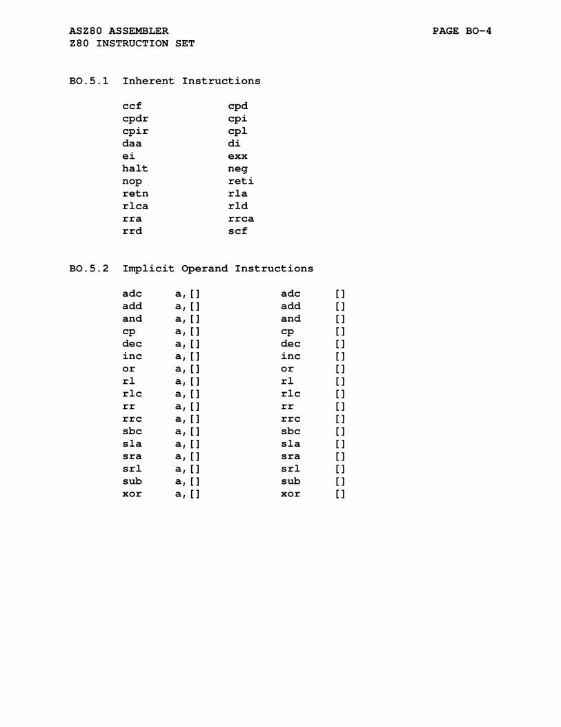
ASZ80 ASSEMBLER PAGE BO-4 Z80 INSTRUCTION SET
BO.5.1 Inherent Instructions
ccf cpd cpdr cpi cpir cpl daa di ei exx halt neg nop reti retn rla rlca rld rra rrca rrd scf
BO.5.2 Implicit Operand Instructions
adc a,[] adc [] add a,[] add [] and a,[] and [] cp a,[] cp [] dec a,[] dec [] inc a,[] inc [] or a,[] or [] rl a,[] rl [] rlc a,[] rlc [] rr a,[] rr [] rrc a,[] rrc [] sbc a,[] sbc [] sla a,[] sla [] sra a,[] sra [] srl a,[] srl [] sub a,[] sub [] xor a,[] xor []
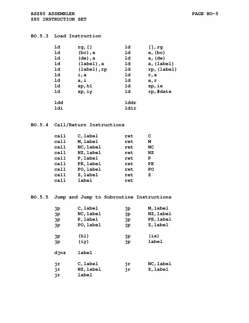
ASZ80 ASSEMBLER PAGE BO-5 Z80 INSTRUCTION SET
BO.5.3 Load Instruction
ld rg,[] ld [],rg ld (bc),a ld a,(bc) ld (de),a ld a,(de) ld (label),a ld a,(label) ld (label),rp ld rp,(label) ld i,a ld r,a ld a,i ld a,r ld sp,hl ld sp,ix ld sp,iy ld rp,#data ldd lddr ldi ldir
BO.5.4 Call/Return Instructions
call C,label ret C call M,label ret M call NC,label ret NC call NZ,label ret NZ call P,label ret P call PE,label ret PE call PO,label ret PO call Z,label ret Z call label ret
BO.5.5 Jump and Jump to Subroutine Instructions
jp C,label jp M,label jp NC,label jp NZ,label jp P,label jp PE,label jp PO,label jp Z,label jp (hl) jp (ix) jp (iy) jp label djnz label jr C,label jr NC,label jr NZ,label jr Z,label jr label

ASZ80 ASSEMBLER PAGE BO-6 Z80 INSTRUCTION SET
BO.5.6 Bit Manipulation Instructions
bit n,[] res n,[] set n,[]
BO.5.7 Interrupt Mode and Reset Instructions
im n im n im n rst n
BO.5.8 Input and Output Instructions
in a,(n) in rg,(c) ind indr ini inir out (n),a out (c),rg outd otdr outi otir
BO.5.9 Register Pair Instructions
add hl,rp add ix,rp add iy,rp adc hl,rp sbc hl,rp ex (sp),hl ex (sp),ix ex (sp),iy ex de,hl ex af,af' push rp pop rp

ASZ80 ASSEMBLER PAGE BO-7 Z80 INSTRUCTION SET
BO.5.10 HD64180/Z180 Specific Instructions
in0 rg,(n) out0 (n),rg otdm otdmr otim otimr mlt bc mlt de mlt hl mlt sp slp tst a tstio #data
APPENDIX BP
ASZ280 ASSEMBLER
BP.1 ACKNOWLEDGMENT
The ASZ280 cross assembler was written by John Coffman.
John Coffman johninsd at gmail dot com
The ASZ280 assembler is a completely table driven assem- bler. This assembler can process Z280 (default), HD64180 (Z180), and Z80 code. The following processor specific assem- bler directives specify which processor to target and with specific instruction options when processing the input assembler files.
BP.2 PROCESSOR SPECIFIC DIRECTIVES
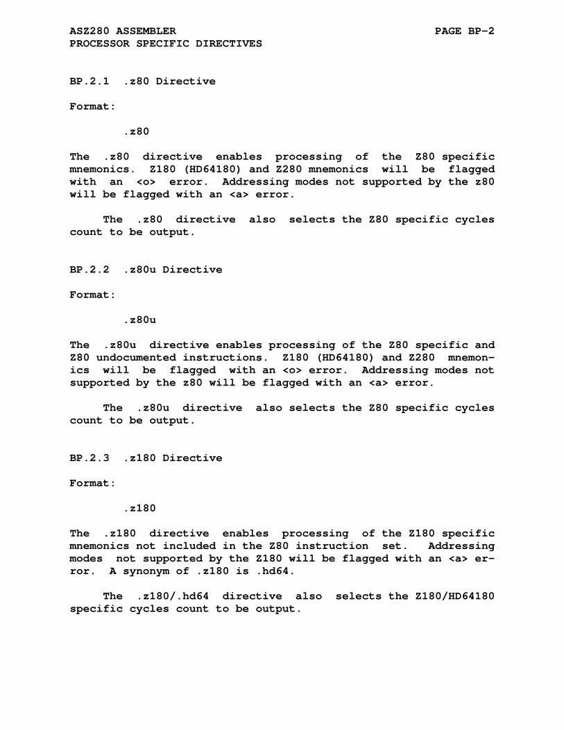
ASZ280 ASSEMBLER PAGE BP-2 PROCESSOR SPECIFIC DIRECTIVES
BP.2.1 .z80 Directive
Format:
.z80
The .z80 directive enables processing of the Z80 specific mnemonics. Z180 (HD64180) and Z280 mnemonics will be flagged with an <o> error. Addressing modes not supported by the z80 will be flagged with an <a> error.
The .z80 directive also selects the Z80 specific cycles count to be output.
BP.2.2 .z80u Directive
Format:
.z80u
The .z80u directive enables processing of the Z80 specific and Z80 undocumented instructions. Z180 (HD64180) and Z280 mnemon- ics will be flagged with an <o> error. Addressing modes not supported by the z80 will be flagged with an <a> error.
The .z80u directive also selects the Z80 specific cycles count to be output.
BP.2.3 .z180 Directive
Format:
.z180
The .z180 directive enables processing of the Z180 specific mnemonics not included in the Z80 instruction set. Addressing modes not supported by the Z180 will be flagged with an <a> er- ror. A synonym of .z180 is .hd64.
The .z180/.hd64 directive also selects the Z180/HD64180 specific cycles count to be output.

ASZ280 ASSEMBLER PAGE BP-3 PROCESSOR SPECIFIC DIRECTIVES
BP.2.4 .z280 Directive
Format:
.z280
The .z280 directive enables processing of the Z280 specific mnemonics, includes i/o instructions, but excludes all privileged instructions. Addressing modes not supported by the Z280 will be flagged with an <a> error.
The .z280 directive also selects the Z280 specific cycles count to be output.
BP.2.5 .z280n Directive
Format:
.z280n
The .z280n directive enables processing of the Z280 specific mnemonics, excludes i/o instructions, and excludes all privileged instructions. Addressing modes not supported by the Z280 will be flagged with an <a> error.
The .z280n directive also selects the Z280 specific cycles count to be output.
BP.2.6 .z280p Directive
Format:
.z280p
The .z280p directive enables processing of the Z280 specific mnemonics, includes i/o instructions, and includes all privileged instructions. Addressing modes not supported by the Z280 will be flagged with an <a> error.
The .z280p directive also selects the Z280 specific cycles count to be output.

ASZ280 ASSEMBLER PAGE BP-4 PROCESSOR SPECIFIC DIRECTIVES
BP.2.7 The .__.CPU. Variable
The value of the pre-defined symbol '.__.CPU.' corresponds to the selected processor type. The following table lists the pro- cessor types and associated values for the ASZ280 assembler:
Processor Type .__.CPU. Value -------------- -------------- .z80 0x83 .z80u 0x87 .z180/.hd64 0x8B .z280 0x33 .z280n 0x11 .z280p 0xF3
The variable '.__.CPU.' is by default defined as local and will not be output to the created .rel file. The assembler com- mand line options -g or -a will not cause the local symbol to be output to the created .rel file.
The assembler .globl directive may be used to change the variable type to global causing its definition to be output to the .rel file. The inclusion of the definition of the variable '.__.CPU.' might be a useful means of validating that seperately assembled files have been compiled for the same processor type. The linker will report an error for variables with multiple non equal definitions.

ASZ280 ASSEMBLER PAGE BP-5 PROCESSOR SPECIFIC DIRECTIVES
BP.3 Z280 ADDRESSING AND INSTRUCTIONS
BP.3.1 Registers
Recognized Registers ----------------------------------------------------- 8-bit data registers: A,B,C,D,E,H,L 16-Bit data registers: BC,DE,HL,IX,IY Accumulator/Flag registers: AF,AF' Program Counter: PC Stack Pointer: SP -----------------------------------------------------
BP.3.2 Condition Codes
Condition Codes for Jump, Call, and Return Instructions ----------------------------------------------------- NZ - Not Zero zero bit clear Z - Zero zero bit set NC - No Carry carry bit clear C - Carry carry bit set NV - No Overflow overflow bit clear V - Overflow overflow bit set PE - Parity Even (overflow bit set) PO - Parity Odd (overflow bit clear) NS - No Sign sign bit clear P - Plus sign bit clear S - Sign sign bit set M - Minus sign bit set ----------------------------------------------------- Condition Codes for Jump Relative Instruction ----------------------------------------------------- NZ - Not Zero zero bit clear Z - Zero zero bit set NC - No Carry carry bit clear C - Carry carry bit set -----------------------------------------------------

ASZ280 ASSEMBLER PAGE BP-6 Z280 ADDRESSING AND INSTRUCTIONS
BP.3.3 Z280 Instructions
The following list of instructions (with addressing modes) are available in the Z280 assembler mode.
BP.3.3.1 Instruction Modes -
Addressing Mode Notes ----------------------------------------------------- R 8-bit registers: A,B,C,D,E,H,L RX 16-Bit registers: BC,DE,HL,IX,IY,SP IM Immediate #byte, #word IR Indirect Register (HL) DA Direct Address (address) X Indexed (HL+ofst),ofst(HL) (IX+ofst),ofst(IX) (IY+Ofst),ofst(IY) SX Short Index (HL+ofst),ofst(HL) (IX+ofst),ofst(IX) (IY+ofst),ofst(IY) -128 <= ofst <= 127 RA PC Relative Address [address] 8-bit offset: -128 <= ofst <= 127 16-bit offset: -32768 <= ofst <= 32767 SR Stack Pointer Relative (SP+ofst) BX Base Index (HL+IX),(HL+IY),(IX+IY) -----------------------------------------------------
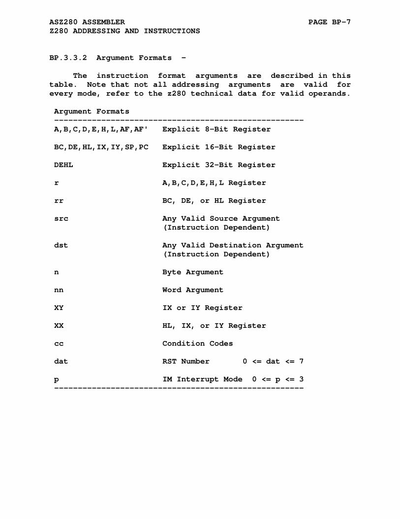
ASZ280 ASSEMBLER PAGE BP-7 Z280 ADDRESSING AND INSTRUCTIONS
BP.3.3.2 Argument Formats -
The instruction format arguments are described in this table. Note that not all addressing arguments are valid for every mode, refer to the z280 technical data for valid operands.
Argument Formats ----------------------------------------------------- A,B,C,D,E,H,L,AF,AF' Explicit 8-Bit Register BC,DE,HL,IX,IY,SP,PC Explicit 16-Bit Register DEHL Explicit 32-Bit Register r A,B,C,D,E,H,L Register rr BC, DE, or HL Register src Any Valid Source Argument (Instruction Dependent) dst Any Valid Destination Argument (Instruction Dependent) n Byte Argument nn Word Argument XY IX or IY Register XX HL, IX, or IY Register cc Condition Codes dat RST Number 0 <= dat <= 7 p IM Interrupt Mode 0 <= p <= 3 -----------------------------------------------------
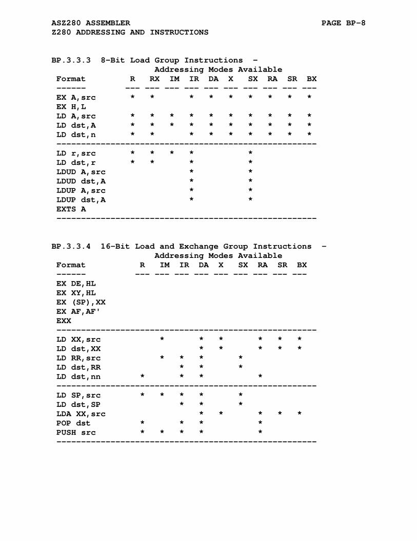
ASZ280 ASSEMBLER PAGE BP-8 Z280 ADDRESSING AND INSTRUCTIONS
BP.3.3.3 8-Bit Load Group Instructions - Addressing Modes Available Format R RX IM IR DA X SX RA SR BX ------ --- --- --- --- --- --- --- --- --- --- EX A,src * * * * * * * * * EX H,L LD A,src * * * * * * * * * * LD dst,A * * * * * * * * * * LD dst,n * * * * * * * * * ----------------------------------------------------- LD r,src * * * * * LD dst,r * * * * LDUD A,src * * LDUD dst,A * * LDUP A,src * * LDUP dst,A * * EXTS A -----------------------------------------------------
BP.3.3.4 16-Bit Load and Exchange Group Instructions - Addressing Modes Available Format R IM IR DA X SX RA SR BX ------ --- --- --- --- --- --- --- --- --- EX DE,HL EX XY,HL EX (SP),XX EX AF,AF' EXX ----------------------------------------------------- LD XX,src * * * * * * LD dst,XX * * * * * LD RR,src * * * * LD dst,RR * * * LD dst,nn * * * * ----------------------------------------------------- LD SP,src * * * * * LD dst,SP * * * LDA XX,src * * * * * POP dst * * * * PUSH src * * * * * -----------------------------------------------------
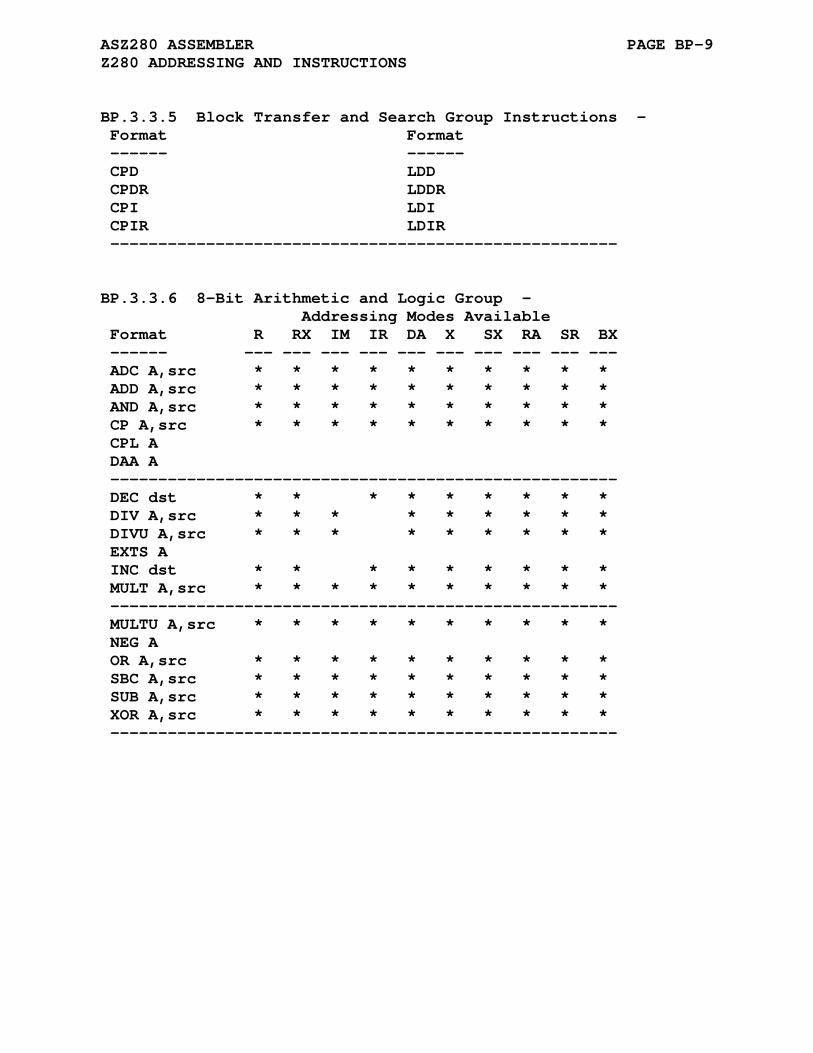
ASZ280 ASSEMBLER PAGE BP-9 Z280 ADDRESSING AND INSTRUCTIONS
BP.3.3.5 Block Transfer and Search Group Instructions - Format Format ------ ------ CPD LDD CPDR LDDR CPI LDI CPIR LDIR -----------------------------------------------------
BP.3.3.6 8-Bit Arithmetic and Logic Group - Addressing Modes Available Format R RX IM IR DA X SX RA SR BX ------ --- --- --- --- --- --- --- --- --- --- ADC A,src * * * * * * * * * * ADD A,src * * * * * * * * * * AND A,src * * * * * * * * * * CP A,src * * * * * * * * * * CPL A DAA A ----------------------------------------------------- DEC dst * * * * * * * * * DIV A,src * * * * * * * * * DIVU A,src * * * * * * * * * EXTS A INC dst * * * * * * * * * MULT A,src * * * * * * * * * * ----------------------------------------------------- MULTU A,src * * * * * * * * * * NEG A OR A,src * * * * * * * * * * SBC A,src * * * * * * * * * * SUB A,src * * * * * * * * * * XOR A,src * * * * * * * * * * -----------------------------------------------------
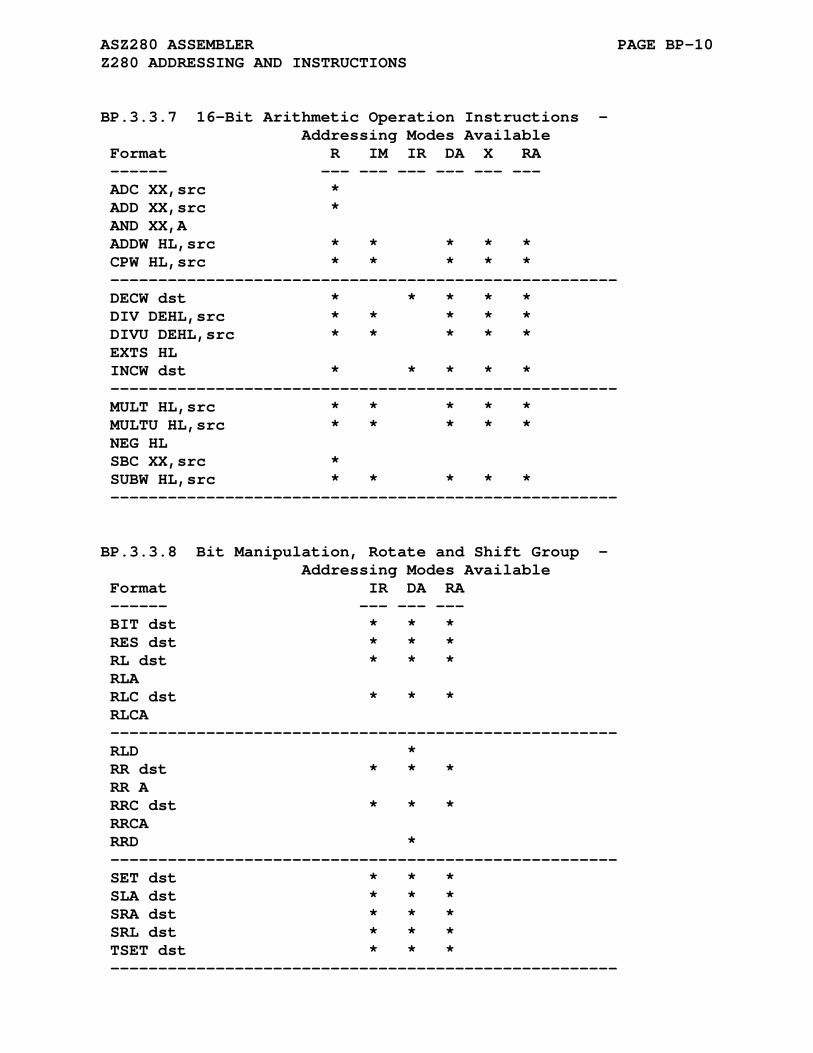
ASZ280 ASSEMBLER PAGE BP-10 Z280 ADDRESSING AND INSTRUCTIONS
BP.3.3.7 16-Bit Arithmetic Operation Instructions - Addressing Modes Available Format R IM IR DA X RA ------ --- --- --- --- --- --- ADC XX,src * ADD XX,src * AND XX,A ADDW HL,src * * * * * CPW HL,src * * * * * ----------------------------------------------------- DECW dst * * * * * DIV DEHL,src * * * * * DIVU DEHL,src * * * * * EXTS HL INCW dst * * * * * ----------------------------------------------------- MULT HL,src * * * * * MULTU HL,src * * * * * NEG HL SBC XX,src * SUBW HL,src * * * * * -----------------------------------------------------
BP.3.3.8 Bit Manipulation, Rotate and Shift Group - Addressing Modes Available Format IR DA RA ------ --- --- --- BIT dst * * * RES dst * * * RL dst * * * RLA RLC dst * * * RLCA ----------------------------------------------------- RLD * RR dst * * * RR A RRC dst * * * RRCA RRD * ----------------------------------------------------- SET dst * * * SLA dst * * * SRA dst * * * SRL dst * * * TSET dst * * * -----------------------------------------------------
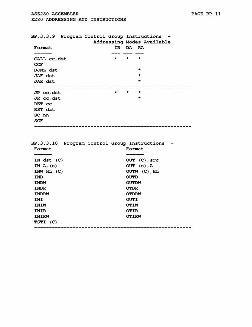
ASZ280 ASSEMBLER PAGE BP-11 Z280 ADDRESSING AND INSTRUCTIONS
BP.3.3.9 Program Control Group Instructions - Addressing Modes Available Format IR DA RA ------ --- --- --- CALL cc,dst * * * CCF DJNZ dst * JAF dst * JAR dst * ----------------------------------------------------- JP cc,dst * * * JR cc,dst * RET cc RST dat SC nn SCF -----------------------------------------------------
BP.3.3.10 Program Control Group Instructions - Format Format ------ ------ IN dst,(C) OUT (C),src IN A,(n) OUT (n),A INW HL,(C) OUTW (C),HL IND OUTD INDW OUTDW INDR OTDR INDRW OTDRW INI OUTI INIW OTIW INIR OTIR INIRW OTIRW TSTI (C) -----------------------------------------------------

ASZ280 ASSEMBLER PAGE BP-12 Z280 ADDRESSING AND INSTRUCTIONS
BP.3.3.11 CPU Control Group Instructions - Format Format ------ ------ DI mask LDCTL dst,src EI mask NOP HALT PCACHE IM p RETI LD A,src RETIL LD src,A RETN -----------------------------------------------------
BP.3.3.12 Extended Instructions - Format Format ------ ------ EPUM src EPUF MEPU dst EPUI -----------------------------------------------------
BP.3.4 Z280 Excution Cycles
The instruction cycle timing was taken from Appendix E of the Z280 CPU manual. They are greatly influenced by the con- tents of the cache.
Z280 Manual Appendix E Excerpt
The autonomous operation of the three stages in the Z280 cpu instruction pipeline makes it difficult to calculate exact instruction execution times. Further- more, execution times are affected by cache activity; the current cache contents determine the number of ex- ternal memory transactions made during the fetch exe- cution of a given instruction.
Thus all timings are approximate and should be looked upon as the smallest number of cycles.

ASZ280 ASSEMBLER PAGE BP-13 Z280 ADDRESSING AND INSTRUCTIONS
BP.4 Z80/HD64180 ADDRESSING AND INSTRUCTIONS
The following list specifies the format for each Z80/HD64180 addressing mode supported by ASZ280:
#data immediate data byte or word data n byte value rg a byte register a,b,c,d,e,h,l rp a register pair bc,de,hl (hl) implied addressing or register indirect addressing (label) direct addressing (ix+offset) indexed addressing with offset(ix) an offset label call/jmp/jr label
The terms data, n, label, and offset, may all be expressions. The terms dir and offset are not allowed to be external refer- ences. The following tables list all Z80/HD64180 mnemonics recognized by the ASRAB assembler. The designation [] refers to a required addressing mode argument.
Note that not all addressing modes are valid with every in- struction, refer to the Z80/HD64180 technical data for valid modes.
BP.4.1 Inherent Instructions
ccf cpd cpdr cpi cpir cpl daa di ei exx halt neg nop reti retn rla rlca rld rra rrca rrd scf

ASZ280 ASSEMBLER PAGE BP-14 Z80/HD64180 ADDRESSING AND INSTRUCTIONS
BP.4.2 Implicit Operand Instructions
adc a,[] adc [] add a,[] add [] and a,[] and [] cp a,[] cp [] dec a,[] dec [] inc a,[] inc [] or a,[] or [] rl a,[] rl [] rlc a,[] rlc [] rr a,[] rr [] rrc a,[] rrc [] sbc a,[] sbc [] sla a,[] sla [] sra a,[] sra [] srl a,[] srl [] sub a,[] sub [] xor a,[] xor []
BP.4.3 Load Instruction
ld rg,[] ld [],rg ld (bc),a ld a,(bc) ld (de),a ld a,(de) ld (label),a ld a,(label) ld (label),rp ld rp,(label) ld i,a ld r,a ld a,i ld a,r ld sp,hl ld sp,ix ld sp,iy ld rp,#data ldd lddr ldi ldir

ASZ280 ASSEMBLER PAGE BP-15 Z80/HD64180 ADDRESSING AND INSTRUCTIONS
BP.4.4 Call/Return Instructions
call C,label ret C call M,label ret M call NC,label ret NC call NZ,label ret NZ call P,label ret P call PE,label ret PE call PO,label ret PO call Z,label ret Z call label ret
BP.4.5 Jump and Jump to Subroutine Instructions
jp C,label jp M,label jp NC,label jp NZ,label jp P,label jp PE,label jp PO,label jp Z,label jp (hl) jp (ix) jp (iy) jp label djnz label jr C,label jr NC,label jr NZ,label jr Z,label jr label
BP.4.6 Bit Manipulation Instructions
bit n,[] res n,[] set n,[]
BP.4.7 Interrupt Mode and Reset Instructions
im n im n im n rst n
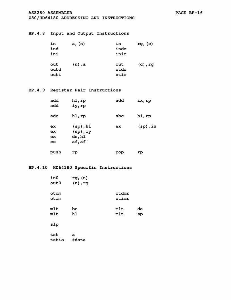
ASZ280 ASSEMBLER PAGE BP-16 Z80/HD64180 ADDRESSING AND INSTRUCTIONS
BP.4.8 Input and Output Instructions
in a,(n) in rg,(c) ind indr ini inir out (n),a out (c),rg outd otdr outi otir
BP.4.9 Register Pair Instructions
add hl,rp add ix,rp add iy,rp adc hl,rp sbc hl,rp ex (sp),hl ex (sp),ix ex (sp),iy ex de,hl ex af,af' push rp pop rp
BP.4.10 HD64180 Specific Instructions
in0 rg,(n) out0 (n),rg otdm otdmr otim otimr mlt bc mlt de mlt hl mlt sp slp tst a tstio #data

ASZ280 ASSEMBLER PAGE BP-17 Z80/HD64180 ADDRESSING AND INSTRUCTIONS
BP.4.11 Z80 Undocumented Instructions
op = adc, add, and, cp, or, sbc, sub, xor op a,ixh op a,ixl op a,iyh or a,iyl op = dec, inc op ixh inc ixl op iyh inc iyl in ixh,(c) in ixl,(c) in iyh,(c) in iyl,(c) ld ixh,r r = a, b, c, d, e ld ixl,r r = a, b, c, d, e ld iyh,r r = a, b, c, d, e ld iyl,r r = a, b, c, d, e ld r,ixh r = a, b, c, d, e ld r,ixl r = a, b, c, d, e ld r,iyh r = a, b, c, d, e ld r,iyl r = a, b, c, d, e ld ixh,#n ld ixl,#n ld iyh,#n ld iyl,#n ld ixh,ixh ld ixl,ixh ld ixh,ixl ld ixl,ixl ld iyh,iyh ld iyl,iyh ld iyh,iyl ld iyl,iyl sll offset(ix) sll offset(iy) sll a sll b sll c sll d sll e sll h sll l