should i turn my water system into a power plant?
TRANSCRIPT

Scott Duren, PE - Brown and CaldwellPeter Brooks – NLine Energy
PNWS-AWWA Conference, Boise, Idaho
May 4, 2016
Should I turn my water system into a power plant?
• How will this impact my mission?
• What are the benefits?
• Where should I do this?
• What am I missing?
The Big Questions
Brown and Caldwell 2
• Product Quality
• Customer Satisfaction
• Employee and Leadership Development
• Operational Optimization
• Financial Viability
• Infrastructure Stability
• Operational Resiliency
• Community Sustainability
• Water Resource Adequacy
• Stakeholder Understanding & Support
Core mission goals cannot be compromised
Brown and Caldwell 3

• Product Quality
• Customer Satisfaction
• Employee and Leadership Development
• Operational Optimization
• Financial Viability
• Infrastructure Stability
• Operational Resiliency
• Community Sustainability
• Water Resource Adequacy
• Stakeholder Understanding & Support
Avoid Impacts to Critical Attributes
Brown and Caldwell 4

• Product Quality
• Customer Satisfaction
• Employee and Leadership Development
• Operational Optimization
• Financial Viability
• Infrastructure Stability
• Operational Resiliency
• Community Sustainability
• Water Resource Adequacy
• Stakeholder Understanding & Support
Provide Benefits to Key Practice Areas
Brown and Caldwell 5

Benefits of Hydroelectric Power
Brown and Caldwell 6
• <15 year payback
• Positive cash flow in year one
Financing/ Economics
• Climate Change/Sustainability
• Negligible footprint vs. other renewablesEnvironmental
• 50-100 year asset life
• New models @ 1/3 cost of old hydroTechnology
• FERC Notice of Intent (Exemption)Regulations

• High Head, Low Flow
• Energy Dissipaters
• Pressure Reducing Valves
• Minimum Avg Flow >4.5 cfs
• Minimum head 100 ft
• Low Head, High Flow
• Canal Drops
• WWTP Outfalls
• Minimum Avg Flow > 30 cfs
• Minimum head 10 ft
Potential Sites for In-Conduit Hydro
Brown and Caldwell 7
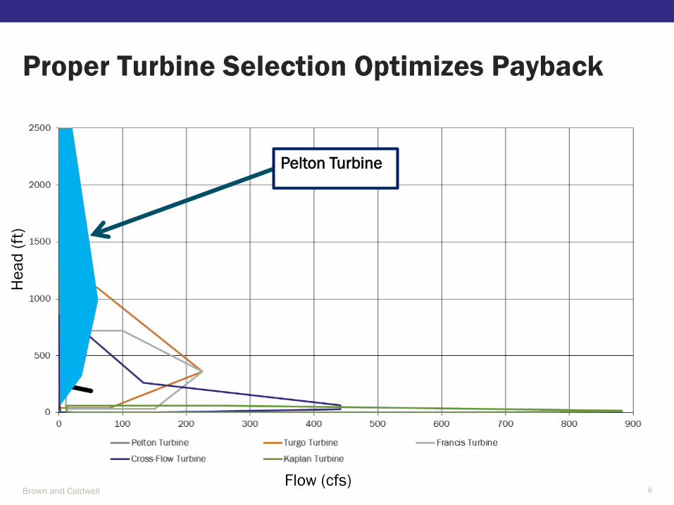
Proper Turbine Selection Optimizes Payback
Brown and Caldwell 8
Pelton Turbine
He
ad
(ft
)
Flow (cfs)

Pelton Turbines Suitable for Low Flow/High Head
Brown and Caldwell 9
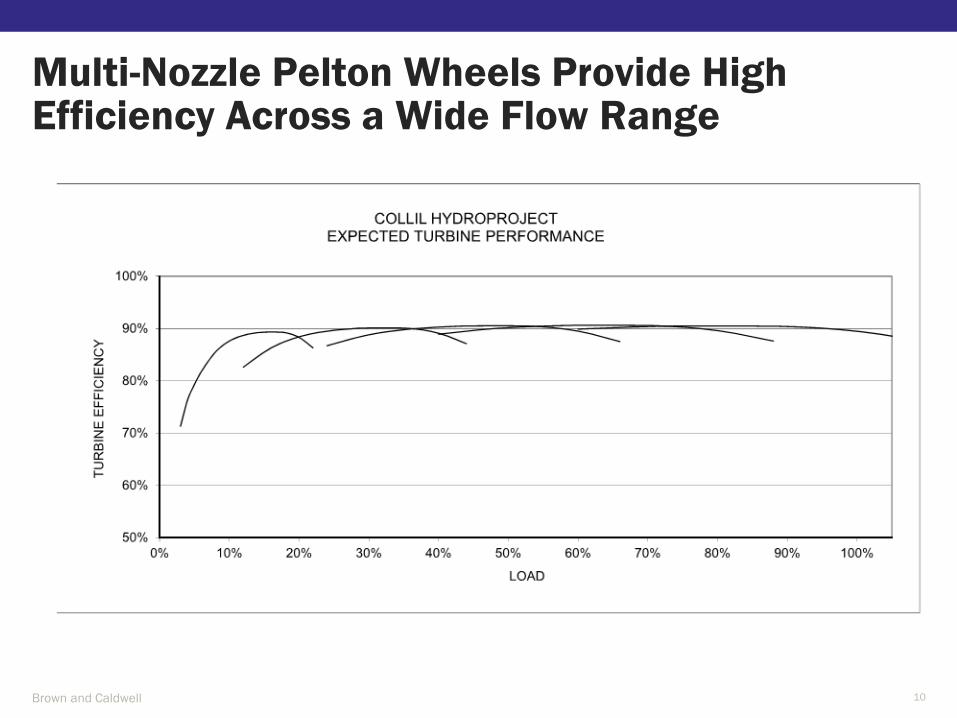
Multi-Nozzle Pelton Wheels Provide High Efficiency Across a Wide Flow Range
Brown and Caldwell 10

Vertical Pelton Wheel Options
Brown and Caldwell 11

Proper Turbine Selection Optimizes Payback
Brown and Caldwell 12
Turgo Turbine
Francis Turbine
Cross-Flow
Turbine
He
ad
(ft
)
Flow (cfs)
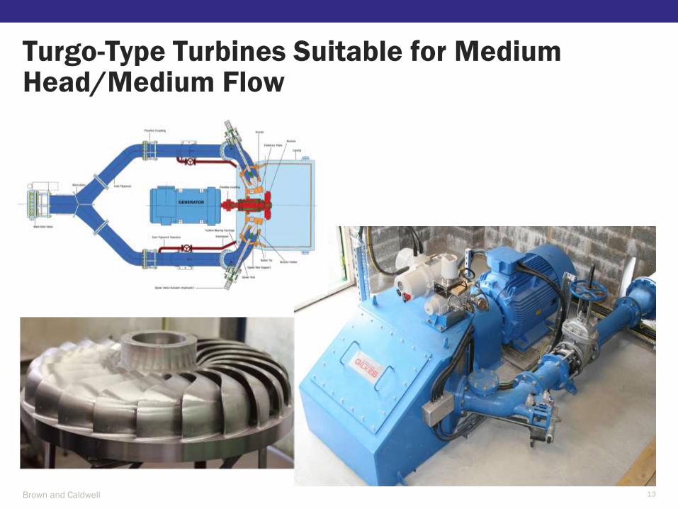
Turgo-Type Turbines Suitable for Medium Head/Medium Flow
Brown and Caldwell 13
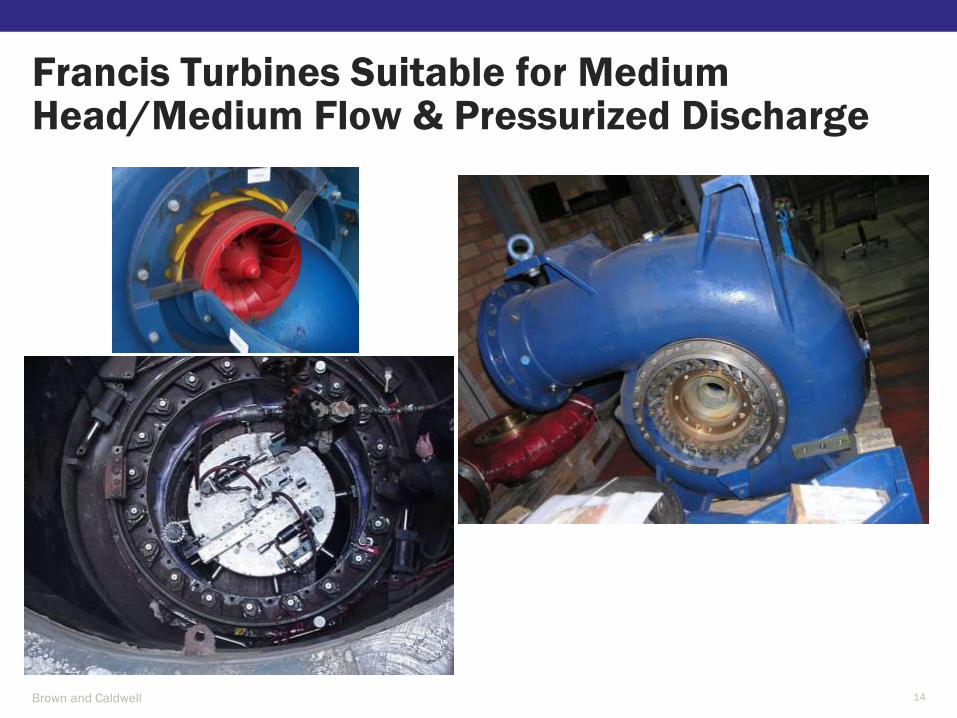
Francis Turbines Suitable for Medium Head/Medium Flow & Pressurized Discharge
Brown and Caldwell 14

Ossberger/Crossflow Turbines Suitable for Medium Head/Medium Flow
Brown and Caldwell 15

Proper Turbine Selection Optimizes Payback
Brown and Caldwell 16
Kaplan TurbineHe
ad
(ft
)
Flow (cfs)

Kaplan Turbines Suitable for Low Head/High Flow
Brown and Caldwell 17
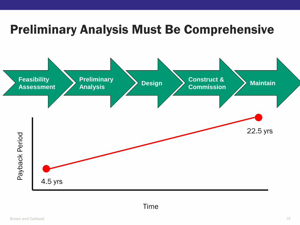
Preliminary Analysis Must Be Comprehensive
Brown and Caldwell 18
Feasibility
Assessment
Preliminary
AnalysisDesign
Construct &
CommissionMaintain
Time
Pa
yba
ck
Pe
rio
d
4.5 yrs
22.5 yrs

Distance to Interconnection Point Adds Substantial Capital Costs
Brown and Caldwell 19

Grid Availability Must be Analyzed
Brown and Caldwell 20
1.4MW Hydroelectric
Facility Located at End of
Power Grid
3,700 LF of #2
Aluminum Overhead
Conductor
2,600 LF of #2
Aluminum Buried
Conductor
Potential for over $600,000 in additional
capital costs to upgrade to existing power lines
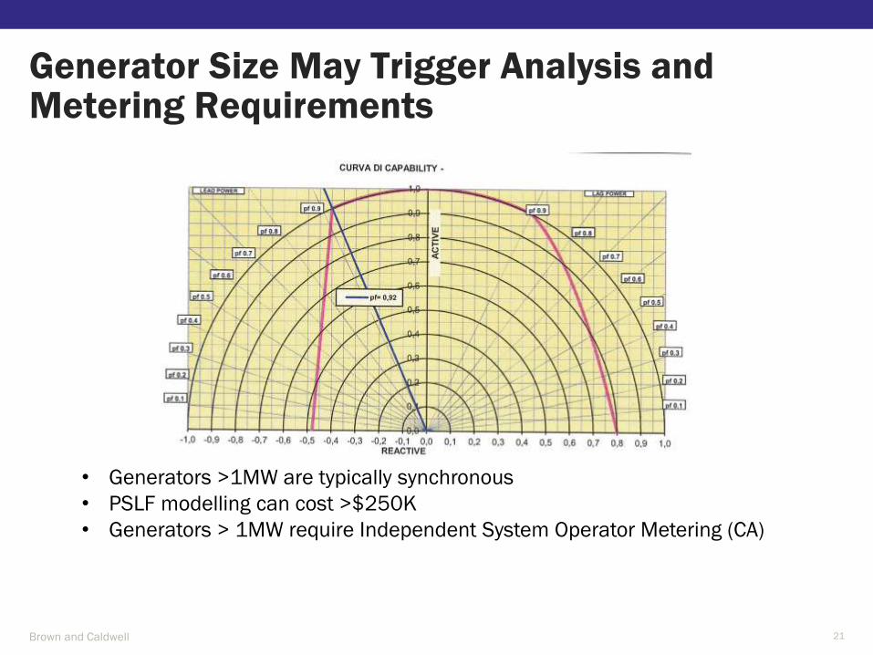
Generator Size May Trigger Analysis and Metering Requirements
Brown and Caldwell 21
• Generators >1MW are typically synchronous
• PSLF modelling can cost >$250K
• Generators > 1MW require Independent System Operator Metering (CA)

Flow Projections Impact Turbine Selection and Power Revenues
Brown and Caldwell 22

Efficiency Throughout Range of Flows Maximizes Return on Investment
Brown and Caldwell 23
90% of Flow Range
Canyon Hydro
5-Nozzle Vertical
Pelton
Gilkes
2-Jet Turgo
Gilkes
Francis
Turbine Classification Impulse Impulse Reaction
Turbine Technology Pelton Turgo Francis
Rated Flow (cfs) 45 54 45
Minimum Flow (cfs) 4.5 10 12
Rated Head (ft) 400 405 353
Capacity Rating (kW) 1,440 1,510 1,040
Water-to-Wire Net Efficiency 85.7% 77.2% 86.9%
Annual Generation (kWh) 5,110,000 4,317,000 3,642,000
Water-to-Wire Package Cost $1,575,000 $1,269,000 $1,520,000
Process future flows? Yes Yes Yes
NID Loma Rica - Turbine Technology Summary

Distribution System Control Valves Can Reduce Power Generation Revenues
Brown and Caldwell 24
3100
3200
3300
3400
3500
3600
3700
0 10000 20000 30000 40000 50000 60000 70000
Ele
va
tio
n a
nd
HG
L (
ft)
Distance (ft)
Pipe invert
30 CFS - Model
35 CFS - Model
40 CFS - Model
45 CFS - Model
50 CFS - Model
55 CFS - Model
30 CFS - Field
35 CFS - Field
40 CFS - Field
45 CFS - Field
50 CFS - Field
55 CFS - FieldIntake Turnout Turnout
Hydro
30 feet of head results in $1.15M of life-cycle cost

Debris In Existing Pipelines Can Reduce Power Generation Equipment Run-time
Brown and Caldwell 25

One Month of Downtime Costs $30,000 in Lost Revenue Alone
Brown and Caldwell 26
Needle Valves
Control Flow Rate
at Each Nozzle
Nozzle Sized for 1-
inch Diameter
Fully Open
Repair Valves
Require Long
Lead Time

Lining Inspection and Repair Can be Cost Prohibitive
Brown and Caldwell 27

Screening Equipment Adds Capital and Maintenance Costs
Brown and Caldwell 28

Francis Turbine Load Rejection Can Create Transient Surge Event
Brown and Caldwell 29
Ramos, Hydro Review Worldwide, 2010

Surge Tanks Are Expensive and Require Maintenance
Brown and Caldwell 30

Pelton Wheel Nozzle Deflectors Eliminate “Runaway Turbine” Effect
Brown and Caldwell 31
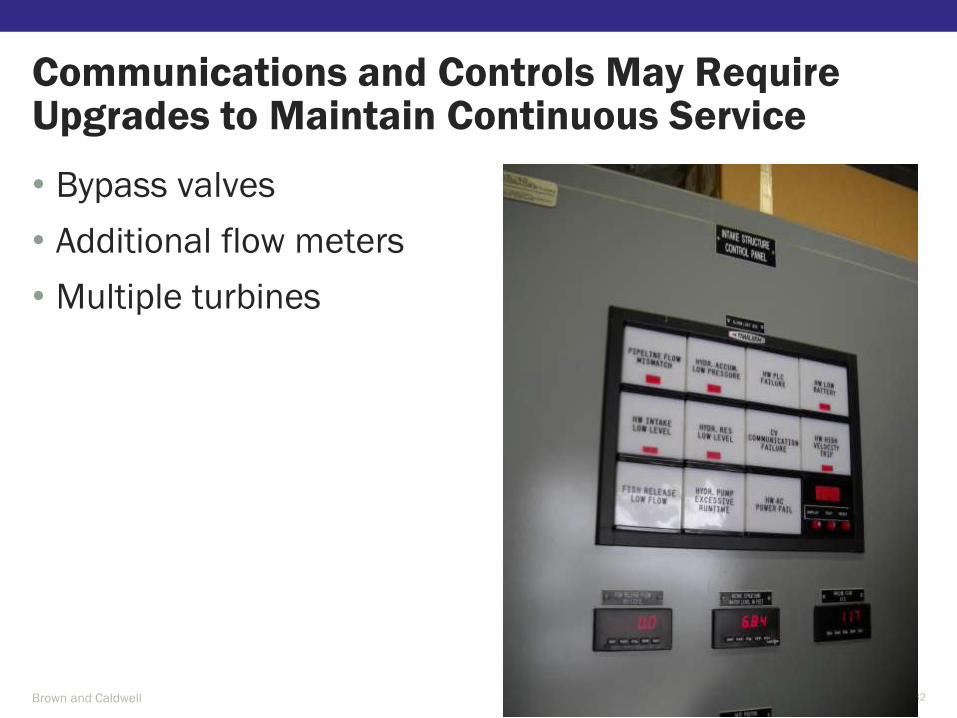
• Bypass valves
• Additional flow meters
• Multiple turbines
Communications and Controls May Require Upgrades to Maintain Continuous Service
Brown and Caldwell 32
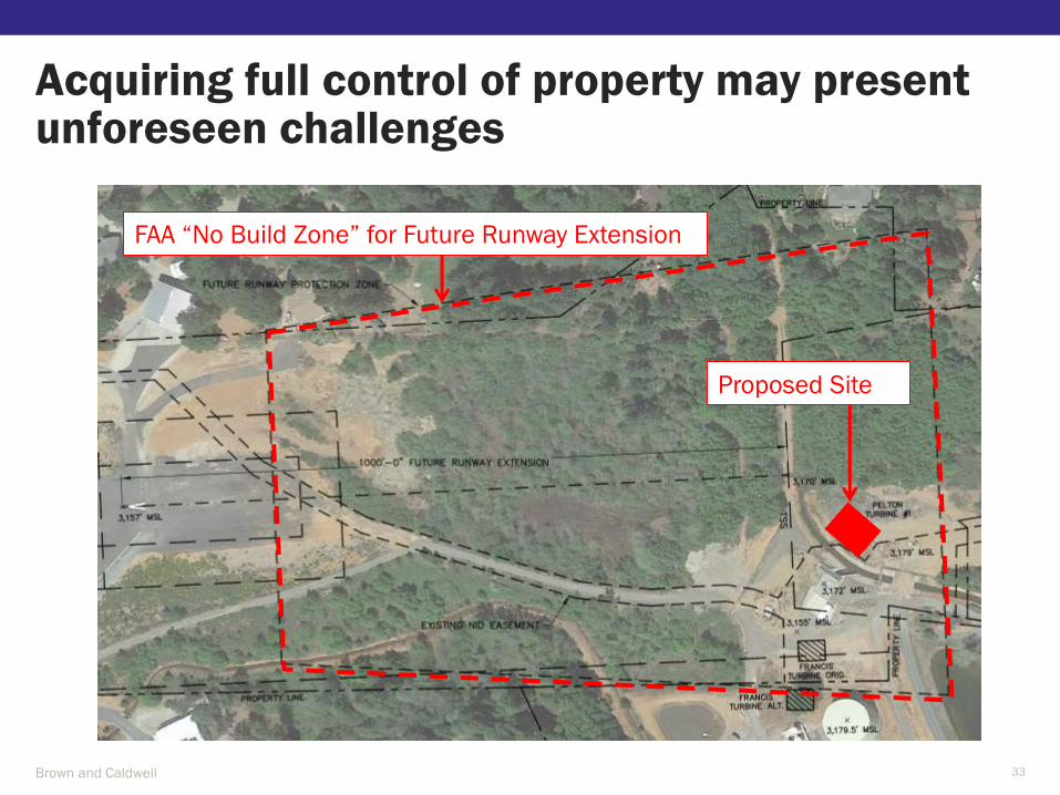
Acquiring full control of property may present unforeseen challenges
Brown and Caldwell 33
Proposed Site
FAA “No Build Zone” for Future Runway Extension
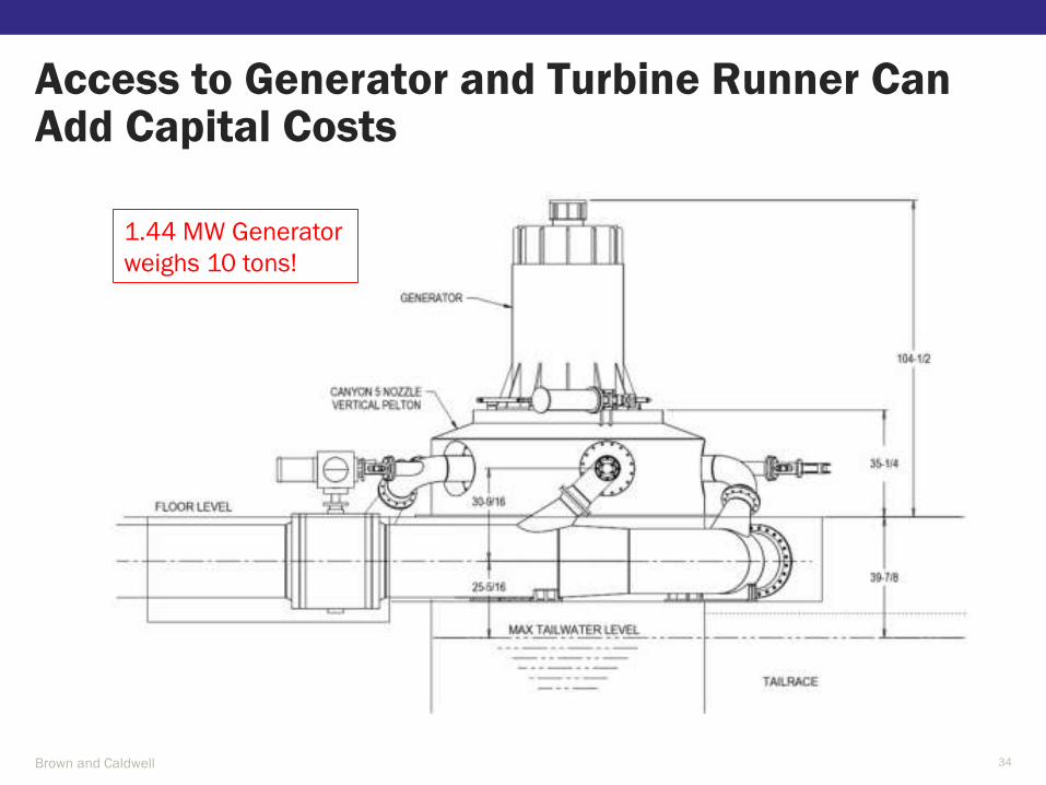
Access to Generator and Turbine Runner Can Add Capital Costs
Brown and Caldwell 34
1.44 MW Generator
weighs 10 tons!

TIV and Runner Housing Encased in Concrete
Brown and Caldwell 35

Turbine Runner Suspended Above Tailrace
Brown and Caldwell 36

Large Access Required to Remove Runner
Brown and Caldwell 37

Providing Crane Access to Generator Can Add Substantial Costs
Brown and Caldwell 38

Operator Safety Must be Considered
Brown and Caldwell 39

• Knowledge of water system design and operations is key to successfully identifying all life-cycle costs of a project
• A thorough preliminary evaluation allows owners to have confidence in determining project feasibility
A Thorough Preliminary Design is Necessary
Brown and Caldwell 40

Contact Scott Duren at [email protected]
or (503) 820-5574 for additional information
Questions?
Brown and Caldwell 41