siae - als pdh radio family - manual
TRANSCRIPT

ALS Access Link SeriesPDH radio family
User manual
MN.00183.E - 003Volume 1/1

The information contained in this handbook is subject to change without notice.
Property of Siae Microelettronica S.p.A. All rights reserved according to the law and according to the inter-national regulations. No part of this document may be reproduced or transmitted in any form or by anymeans, electronic or mechanical, without written permission from Siae Microelettronica S.p.A.
Unless otherwise specified, reference to a Company, name, data and address produced on the screen dis-played is purely indicative aiming at illustrating the use of the product.
MS-DOS®, MS Windows® are trademarks of Microsoft Corporation.
HP®, HP OpenView NNM and HP–UX are Hewlett Packard Company registered trademarks.
UNIX is a UNIX System Laboratories registered trademark.
Oracle® is a Oracle Corporation registered trademark.
Linux term is a trademark registered by Linus Torvalds, the original author of the Linux operating system.Linux is freely distributed according the GNU General Public License (GPL).
Other products cited here in are constructor registered trademarks.

ALS - MN.00183.E - 003 1
Contents
Section 1.USER GUIDE 11
1 DECLARATION OF CONFORMITY ..............................................................................11
2 FIRST AID FOR ELECTRICAL SHOCK AND SAFETY RULES .........................................12
2.1 FIRST AID FOR ELECTRICAL SHOCK....................................................................12
2.1.1 Artificial respiration .................................................................................12
2.1.2 Treatment of burns .................................................................................12
2.2 SAFETY RULES .................................................................................................13
2.3 CORRECT DISPOSAL OF THIS PRODUCT (Waste electrical & electronic equipment) ....15
2.4 INTERNAL BATTERY ..........................................................................................15
3 PURPOSE AND STRUCTURE OF THE MANUAL............................................................16
3.1 PURPOSE OF THE MANUAL.................................................................................16
3.2 AUDIENCE BASIC KNOWLEDGE ..........................................................................16
3.3 STRUCTURE OF THE MANUAL .............................................................................16
Section 2.DESCRIPTIONS AND SPECIFICATION 19
4 ABBREVIATION LIST................................................................................................19
4.1 LIST OF ABBREVIATIONS...................................................................................19
5 SYSTEM PRESENTATION ..........................................................................................21
5.1 RADIO SYSTEM OVERVIEW ................................................................................21
5.1.1 General .................................................................................................21
5.2 RECOMMENDATION ..........................................................................................21
5.3 APPLICATION ...................................................................................................21
5.4 SYSTEM ARCHITECTURE....................................................................................22
5.4.1 Modular IDU...........................................................................................22
5.4.2 Compact IDU unit ...................................................................................23
5.4.3 Modular IDU Plus ....................................................................................23
5.4.4 IDU Plus Compact Unit (5.4.4)..................................................................24
5.4.5 ODU......................................................................................................24
5.5 MANAGEMENT SYSTEM......................................................................................25

2 ALS - MN.00183.E - 003
5.5.1 Hardware platform ..................................................................................25
5.5.2 Management ports ..................................................................................25
5.5.3 Protocols ...............................................................................................25
6 EQUIPMENT TECHNICAL SPECIFICATIONS...............................................................28
6.1 TECHNICAL SPECIFICATIONS.............................................................................28
6.2 SERVICE CHANNELS .........................................................................................28
6.3 TRANSMISSION CAPACITY.................................................................................29
6.4 POWER SUPPLY, CONSUMPTION AND MECHANICAL CHARACTERISTICS ...................31
7 CHARACTERISTICS OF THE INDOOR UNIT ...............................................................40
7.1 GENERAL.........................................................................................................40
7.2 TRIBUTARY INTERFACE .....................................................................................40
7.2.1 2 Mbit/s interface....................................................................................40
7.2.2 34 Mbit/s interface ..................................................................................41
7.2.3 Ethernet interface ...................................................................................41
7.3 STM-1 INTERFACE ............................................................................................41
7.3.1 Characteristics of STM-1 electrical interface................................................42
7.4 SERVICE CHANNEL INTERFACE...........................................................................43
7.4.1 2 Mbit/s wayside interface........................................................................43
7.4.2 64 kbit/s co–directional interface ..............................................................43
7.4.3 64 kbit/s contra–directional interface V.11 .................................................44
7.4.4 Analogue interface ..................................................................................44
7.4.5 9600 bit/s low speed synchronous/asynchronous data .................................44
7.4.6 9600 or 2x4800 bit/s low speed asynchronous data.....................................44
7.4.7 Alarm interface.......................................................................................44
7.4.8 Network Management Interface ................................................................45
7.5 MODULATOR/DEMODULATOR .............................................................................46
7.6 CABLE INTERFACE ............................................................................................46
7.7 AVAILABLE LOOPS ............................................................................................46
8 DESCRIPTION OF THE MODULAR IDU FOR 2 OR 34 Mbit/s TRIBUTARIES ................47
8.1 1+0/1+1 MODULAR IDU VERSION ......................................................................47
8.1.1 LIM .......................................................................................................47
8.1.2 Circuit description ...................................................................................47
8.1.3 RIM.......................................................................................................50
8.1.3.1 QAM modulator ........................................................................50
8.1.3.2 QAM demodulator.....................................................................50
8.1.3.3 Power supply ...........................................................................50
8.1.3.4 Telemetry IDU/ODU..................................................................50
8.1.4 CONTROLLER .........................................................................................51
8.1.4.1 Service signals.........................................................................51
8.1.4.2 Equipment software..................................................................51
8.1.4.3 Supervision ports .....................................................................52
8.2 IDU LOOPS ......................................................................................................52
8.2.1 Tributary loop.........................................................................................52
8.2.2 Baseband unit loop .................................................................................52
8.2.3 IDU loop................................................................................................53
9 DESCRIPTION OF THE MODULAR IDU WITH lim ETHERNET (2 Mbit/s TRIBUTARIES + ETHERNET TRAFFIC) ...............................................................................................63
9.1 1+0/1+1 MODULAR IDU....................................................................................63

ALS - MN.00183.E - 003 3
9.1.1 LIM Ethernet: 2 Mbit/s tributaries..............................................................63
9.1.2 Circuit description ...................................................................................63
9.1.3 LIM Ethernet: Ethernet traffic ...................................................................66
9.1.3.1 2 Mbit/s tributaries ...................................................................66
9.1.3.2 Electrical Ethernet interface .......................................................67
9.1.3.3 Front panel LEDs......................................................................67
9.1.3.4 Switch function ........................................................................67
9.1.3.5 Ethernet Full Duplex function .....................................................68
9.1.3.6 Link Loss Forwarding ................................................................68
9.1.3.7 MDI/MDIX cross–over ...............................................................68
9.1.3.8 VLAN functionality ....................................................................69
9.1.3.9 Switch organized by port...........................................................69
9.1.3.10 Switch organized by VLAN ID.....................................................69
9.1.3.11 Layer 2, Priority function, QoS, 802.1p........................................70
9.1.3.12 Layer 3, Priority function, QoS, IP–V4 ToS (DSCP) ........................71
9.1.4 RIM.......................................................................................................71
9.1.4.1 QAM modulator ........................................................................71
9.1.4.2 QAM demodulator.....................................................................71
9.1.4.3 Power supply ...........................................................................71
9.1.4.4 Telemetry IDU/ODU..................................................................72
9.1.5 CONTROLLER .........................................................................................72
9.1.5.1 Service signals.........................................................................72
9.1.6 Equipment software ................................................................................72
9.1.6.1 Supervision ports .....................................................................73
9.2 IDU LOOPS ......................................................................................................74
9.2.1 Tributary loop.........................................................................................74
9.2.2 Baseband unit loop .................................................................................74
9.2.3 IDU loop................................................................................................74
10 DESCRIPTION OF THE IDU COMPACT UNIT FOR 2 Mbit/s TRIBUTARIES ..................81
10.1 IDU COMPACT 1+0/1+1 VERSION ......................................................................81
11 DESCRIPTION OF THE IDU COMPACT UNIT FOR 2 Mbit/s TRIBUTARIES AND FOR ETHERNET TRAFFIC ..........................................................................................82
11.1 VERSION IDU COMPACT ETHERNET 1+0/1+1.......................................................82
12 DESCRIPTION OF THE MODULAR IDU PLUS FOR 2 Mbit/s TRIBUTARIES HIERARCHIC AND NOT HIERARCHIC............................................................................................83
12.1 GENERAL.........................................................................................................83
12.2 COMPOSITION OF TERMINAL 1RU.......................................................................83
12.3 COMPOSITION OF TERMINAL 2RU.......................................................................84
12.4 1RU TERMINAL.................................................................................................84
12.5 2RU TERMINAL.................................................................................................85
12.6 2 Mbit/s TRIBUTARY INTERFACE .........................................................................85
12.7 MATRIX STM1+16E1 (1RU and 2RU) ...................................................................85
12.8 DROP-INSERT (2RU) .........................................................................................85
12.9 NODAL (UP TO 3X2RU)......................................................................................87
12.9.1 Expansion from 2 to 3 nodes ....................................................................87
12.9.2 Reduction from 3 to 2 nodes.....................................................................88
12.10 DYNAMIC MODULATION ....................................................................................90
12.10.1Capacity reduction .................................................................................90
12.10.2Setting with SCT/LCT .............................................................................91
12.11 LIM.................................................................................................................91

4 ALS - MN.00183.E - 003
12.12 CIRCUIT DESCRIPTION......................................................................................91
12.13 RIM ................................................................................................................93
12.13.1QAM modulator .....................................................................................94
12.13.2QAM demodulator ..................................................................................94
12.13.3Power supply.........................................................................................94
12.13.4Telemetry IDU/ODU ...............................................................................94
12.14 EQUIPMENT CONTROLLER..................................................................................94
12.14.1Service signals ......................................................................................95
12.14.2Equipment software ...............................................................................95
12.14.3Supervision ports...................................................................................96
12.15 IDU LOOPS ......................................................................................................96
12.15.1Tributary loop........................................................................................96
12.15.2Baseband unit loop ................................................................................96
12.15.3IDU loop ...............................................................................................97
12.16 EXPANSION 53E1 .............................................................................................97
12.17 SERVICE CHANNEL ADAPTER .............................................................................97
12.18 PROCESSOR 53E1.............................................................................................97
13 DESCRIPTION OF THE IDU COMPACT PLUS FOR 2 Mbit/s TRIBUTARIES AND ETHERNET TRAFFIC................................................................................................................103
13.1 IDU COMPACT PLUS ETHERNET 1+0/1+1 VERSION.............................................103
14 DESCRIPTION OF THE MODULAR IDU FOR E/W REPEATER WITH DROP/INSERT ...104
14.1 GENERAL.......................................................................................................104
14.2 COMPOSITION ...............................................................................................104
14.3 IDU CHARACTERISTICS...................................................................................105
14.3.1 Management of tributaries .....................................................................105
14.3.2 Capacity ..............................................................................................105
14.3.3 E1 switching criteria ..............................................................................105
14.4 CIRCUIT DESCRIPTION....................................................................................105
14.4.1 Matrix .................................................................................................106
14.4.2 Processor.............................................................................................106
14.4.3 RIM.....................................................................................................109
14.4.3.1 QAM modulator ......................................................................109
14.4.3.2 QAM demodulator...................................................................109
14.4.3.3 Power supply .........................................................................109
14.4.3.4 Telemetry IDU/ODU................................................................109
14.4.4 CONTROLLER .......................................................................................110
14.4.4.1 Service signals.......................................................................110
14.4.4.2 Equipment software................................................................110
14.4.4.3 Supervision ports ...................................................................111
14.5 IDU LOOPS ....................................................................................................111
14.5.1 Tributary loop.......................................................................................111
14.5.2 Baseband unit loop ...............................................................................111
14.5.3 IDU loop..............................................................................................112
15 CHARACTERISTICS OF THE OUTDOOR UNIT...........................................................116
15.1 GENERAL.......................................................................................................116
15.2 TECHNICAL SPECIFICATION.............................................................................116
16 OUTDOOR UNIT DESCRIPTION...............................................................................118
16.1 GENERAL.......................................................................................................118

ALS - MN.00183.E - 003 5
16.2 TRANSMIT SECTION........................................................................................118
16.3 RECEIVE SECTION ..........................................................................................119
16.4 CABLE INTERFACE ..........................................................................................119
16.5 ATPC OPERATION ...........................................................................................119
16.6 1+1 Tx SYSTEM.............................................................................................119
16.7 POWER SUPPLY ..............................................................................................120
17 24/48 VOLT DC/DC CONVERTER D52089...............................................................126
17.1 GENERAL.......................................................................................................126
17.2 ENVIRONMENTAL CONDITIONS ........................................................................126
17.3 ELECTRICAL CHARACTERISTICS .......................................................................126
Section 3.INSTALLATION 131
18 INSTALLATION AND PROCEDURES FOR ENSURING THE ELECTROMAGNETIC COMPATIBILITY.....................................................................................................131
18.1 GENERAL INFORMATION TO BE READ BEFORE THE INSTALLATION........................131
18.2 GENERAL.......................................................................................................132
18.3 MECHANICAL INSTALLATION............................................................................132
18.3.1 IDU installation.....................................................................................132
18.3.2 1RU IDU installation ..............................................................................132
18.3.3 2RU IDU installation ..............................................................................132
18.4 ELECTRICAL WIRING.......................................................................................132
18.5 CONNECTIONS TO THE SUPPLY MAINS ..............................................................134
18.6 GROUNDING CONNECTION ..............................................................................134
19 MODULAR IDU USER CONNECTIONS ......................................................................135
19.1 CONNECTOR POSITION FOR 1+0/1+1 MODULAR VERSION ..................................135
19.2 MODULAR VERSION CONNECTORS....................................................................136
20 IDU COMPACT USER CONNECTIONS.......................................................................140
20.1 CONNECTOR POSITION FOR 1+0/1+1 COMPACT VERSION...................................140
21 MODULAR IDU PLUS USER CONNECTIONS .............................................................144
21.1 CONNECTOR POSITION FOR 1+0/1+1 MODULAR IDU PLUS VERSION....................144
22 IDU COMPACT PLUS USER CONNECTIONS..............................................................151
22.1 CONNECTOR USE FOR 1+0/1+1 IDU COMPACT PLUS VERSION.............................151
23 INSTALLATION ONTO THE POLE OF THE ODU WITH SEPARATED ANTENNA ...........157
23.1 INSTALLATION KIT .........................................................................................157
23.2 REQUIRED TOOLS FOR MOUNTING (NOT SUPPLIED) ...........................................158
23.3 INSTALLATION PROCEDURE.............................................................................158
23.4 GROUNDING ..................................................................................................160
24 INSTALLATION ONTO THE WALL OF THE ODU WITH SEPARATED ANTENNA...........174
24.1 INSTALLATION KIT .........................................................................................174

6 ALS - MN.00183.E - 003
24.2 REQUIRED TOOLS FOR MOUNTING (NOT SUPPLIED) ...........................................174
24.3 INSTALLATION PROCEDURE.............................................................................175
24.4 GROUNDING ..................................................................................................177
25 INSTALLATION ONTO THE POLE OF THE ODU WITH INTEGRATED ANTENNA .........188
25.1 FOREWORD ...................................................................................................188
25.2 INSTALLATION KIT .........................................................................................188
25.3 REQUIRED TOOLS FOR MOUNTING (NOT SUPPLIED) ...........................................189
25.4 INSTALLATION PROCEDURE.............................................................................189
25.4.1 Installation onto the pole of the support system and the antenna ................189
25.4.2 Installation of ODU................................................................................190
25.4.3 ODU installation....................................................................................191
25.5 ANTENNA AIMING...........................................................................................191
25.6 COMPATIBILITY..............................................................................................191
25.7 GROUNDING ..................................................................................................192
26 INSTALLATION ONTO THE POLE OF THE ODU WITH INTEGRATED ANTENNA (KIT V32307, V32308, V32309).............................................................................208
26.1 FOREWORD ...................................................................................................208
26.2 INSTALLATION KIT .........................................................................................208
26.3 REQUIRED TOOLS FOR MOUNTING (NOT SUPPLIED) ...........................................209
26.4 INSTALLATION PROCEDURE.............................................................................209
26.5 1+0 MOUNTING PROCEDURES .........................................................................210
26.5.1 Setting antenna polarization...................................................................210
26.5.2 Installation of the centring ring on the antenna.........................................210
26.5.3 Installation of 1+0 ODU support .............................................................210
26.5.4 Installation onto the pole of the assembled structure .................................210
26.5.5 Installation of ODU (on 1+0 support).......................................................210
26.5.6 Antenna aiming ....................................................................................211
26.5.7 ODU grounding.....................................................................................211
26.6 1+1 MOUNTING PROCEDURES .........................................................................211
26.6.1 Installation of Hybrid .............................................................................211
26.6.2 Installation of ODUs (on hybrid for 1+1 version) .......................................212
27 INSTALLATION ONTO THE POLE OF THE ODU WITH RFS INTEGRATED ANTENNA...223
27.1 FOREWORD ...................................................................................................223
27.2 INSTALLATION KIT .........................................................................................223
27.3 REQUIRED TOOLS FOR MOUNTING (NOT SUPPLIED) ...........................................223
27.4 INSTALLATION PROCEDURE.............................................................................224
27.5 1+0 MOUNTING PROCEDURES .........................................................................224
27.5.1 Setting antenna polarization...................................................................224
27.5.2 Installation of the centring ring on the antenna.........................................225
27.5.3 Installation of 1+0 ODU support .............................................................225
27.5.4 Installation onto the pole of the assembled structure .................................225
27.5.5 Installation of ODU (on 1+0 support).......................................................225
27.5.6 Antenna aiming ....................................................................................225
27.5.7 ODU grounding.....................................................................................225
27.6 1+1 MOUNTING PROCEDURES .........................................................................226
27.6.1 Installation of Hybrid .............................................................................226
27.6.2 Installation of ODUs (on hybrid for 1+1 version) .......................................226
28 INSTALLATION ONTO THE POLE OF THE 4 GHz ODU WITH SEPARATED ANTENNA

ALS - MN.00183.E - 003 7
(KIT V32323).........................................................................................................237
28.1 INSTALLATION KIT .........................................................................................237
28.2 REQUIRED TOOLS FOR MOUNTING (NOT SUPPLIED) ...........................................237
28.3 INSTALLATION PROCEDURE.............................................................................237
Section 4.LINE-UP 245
29 LINE–UP OF THE RADIO HOP .................................................................................245
29.1 LINE–UP OF THE RADIO HOP............................................................................245
29.1.1 Equipment configuration ........................................................................245
29.1.2 Antenna alignment and received field measurement ..................................246
29.1.3 Network element configuration ...............................................................246
29.1.4 Radio checks ........................................................................................247
30 LINE–UP OF LIM ETHERNET/2 Mbit/s ....................................................................249
30.1 GENERAL.......................................................................................................249
30.2 LOCAL LAN–1 PORT TO REMOTE LAN–1 PORT TRANSPARENT CONNECTION LAN PER PORT ......................................................................................................249
30.3 LOCAL LAN–1 PORT TO REMOTE LAN–1 PORT TRANSPARENT CONNECTION LAN PER PORT ......................................................................................................254
30.4 3 TO 1 PORT CONNECTIONS ............................................................................257
30.5 3 TO 1 PORT CONNECTIONS, SETTINGS FOR UNTAGGED TRAFFIC ........................258
30.6 3 TO 1 PORT CONNECTIONS, SETTINGS FOR TAGGED AND UNTAGGED TRAFFIC ....260
30.7 3 TO 1 CONNECTIONS: EXAMPLES OF PRIORITY MANAGEMENT ............................261
31 LINE–UP OF LIM FOR EAST/WEST REPEATER WITH DROP/INSERT .......................264
31.1 GENERAL.......................................................................................................264
31.2 BASEBAND CONFIGURATION............................................................................264
31.3 EAST/WEST CONFIGURATION ..........................................................................265
31.4 EAST OR WEST PRESETTING............................................................................266
31.5 TRIBUTARY ENABLING ....................................................................................267
31.6 ONE DIRECTION TRIBUTARY CONNECTION ........................................................268
31.7 PROTECTED TRIBUTARY CONNECTION ..............................................................269
31.8 PROTECTION SETTING (Rx E1 SWITCH) ............................................................269
31.9 PASS–THROUGH E1 CONNECTION ....................................................................270
32 LINE-UP OF THE LINK WITH NODAL IDU ...............................................................271
32.1 OVERVIEW ....................................................................................................271
32.2 EQUIPMENT CONFIGURATION ..........................................................................271
32.3 TRIBUTARY CONFIGURATION ...........................................................................272
32.4 Configuration of the Cross-connection matrix .....................................................272
32.4.1 Tributary - Radio Cross-connection..........................................................273
32.4.2 Tributary - Tributary Cross-connection.....................................................275
33 HOW TO CHANGE ADDRESS ON REMOTE EQUIPMENT WITHOUT LOSING THE CONNECTION .........................................................................................................277
33.1 PROCEDURE...................................................................................................277

8 ALS - MN.00183.E - 003
Section 5.MAINTENANCE 289
34 PERIODICAL CHECKS .............................................................................................289
34.1 GENERAL.......................................................................................................289
34.2 CHECKS TO BE CARRIED OUT ..........................................................................289
35 TROUBLESHOOTING...............................................................................................290
35.1 GENERAL.......................................................................................................290
35.2 TROUBLESHOOTING PROCEDURE .....................................................................290
35.2.1 Loop facilities .......................................................................................290
35.2.2 Alarm messages processing....................................................................291
36 EQUIPMENT CONFIGURATION UPLOAD/SAVE/DOWNLOAD. PARAMETER MODIFICATION AND CREATION OF VIRTUAL CONFIGURATIONS. ..........................292
36.1 SCOPE ..........................................................................................................292
36.2 PROCEDURE...................................................................................................292
36.2.1 General equipment configuration.............................................................292
36.2.2 Addresses and routing table ...................................................................293
36.2.3 Remote Element Table...........................................................................294
37 BACK UP FULL EQUIPMENT CONFIGURATION WITHOUT POSSIBILITY OF MODIFYING THE PARAMETERS .................................................................................................295
37.1 SCOPE ..........................................................................................................295
37.2 CONFIGURATION UPLOAD ...............................................................................295
37.3 CONFIGURATION DOWNLOAD ..........................................................................295
Section 6.PROGRAMMING AND SUPERVISION 297
38 PROGRAMMING AND SUPERVISION.......................................................................297
38.1 GENERAL.......................................................................................................297
Section 7.COMPOSITION 299
39 COMPOSITION OF MODULAR IDU...........................................................................299
39.1 GENERAL.......................................................................................................299
39.2 IDU PART NUMBER .........................................................................................299
39.3 COMPOSITION OF THE INDOOR UNIT................................................................300
40 COMPOSITION OF COMPACT IDU ...........................................................................303
40.1 GENERAL.......................................................................................................303
40.2 ALC IDU PART NUMBER ...................................................................................303

ALS - MN.00183.E - 003 9
41 COMPOSITION OF IDU COMPACT PLUS (ALC PLUS) ...............................................304
41.1 OVERVIEW ....................................................................................................304
41.2 PART NUMBER OF IDU.....................................................................................304
42 COMPOSITION OF IDU PLUS ..................................................................................305
42.1 GENERAL.......................................................................................................305
42.2 IDU PLUS PART NUMBER .................................................................................305
42.3 COMPOSITION OF THE IDU PLUS......................................................................305
42.3.1 1+0 1RU 32E1 Terminal.........................................................................306
42.3.2 1+1 1RU 24E1 Terminal.........................................................................306
42.3.3 1+1 1RU 32E1 terminal .........................................................................307
42.3.4 1+1 terminal 2RU 53E1 .........................................................................307
42.3.5 2RU 32E1 drop/insert ............................................................................308
42.3.6 Nodal 2RU STM1 E1 ..............................................................................308
43 COMPOSITION OF OUTDOOR UNIT.........................................................................309
43.1 GENERAL.......................................................................................................309
Section 8.LISTS AND SERVICES 313
44 LIST OF FIGURES ...................................................................................................313
45 LIST OF TABLES .....................................................................................................319
46 ASSISTANCE SERVICE............................................................................................321

10 ALS - MN.00183.E - 003

ALS - MN.00183.E - 003 11
Section 1.USER GUIDE
1 DECLARATION OF CONFORMITY
SIAE Microelettronica S.p.A. declares that the products:
- digital radio relay system ALS4
- digital radio relay system ALS7
- digital radio relay system ALS8
- digital radio relay system ALS11
- digital radio relay system ALS13
- digital radio relay system ALS15
- digital radio relay system ALS18
- digital radio relay system ALS23
- digital radio relay system ALS25
- digital radio relay system ALS28
- digital radio relay system ALS32
- digital radio relay system ALS38
complies with the essential requirements of article 3 of the R&TTE Directive (1999/5/EC) and therefore ismarked CE.
The following standards have been applied:
- EN 60950-1: 2006 “Safety of information technology equipment”.
- EN 301 489–4 V.1.3.1 (2002–8): “Electromagnetic compatibility and radio spectrum Matters (ERM);Electromagnetic Compatibility (EMC) standard for radio equipment and services; Part 4. Specific con-ditions for fixed radio links and ancillary equipment and services”
- ETSI EN 301 751 V.1.1. (2002–12): “Fixed Radio Systems; Point–to point equipment and antennas;generic harmonized standard for point–to–point digital fixed radio systems and antennas covering theessential requirements under article 3.2 of the 1999/5/EC Directive”.

12 ALS - MN.00183.E - 003
2 FIRST AID FOR ELECTRICAL SHOCK AND SAFETY RULES
2.1 FIRST AID FOR ELECTRICAL SHOCK
Do not touch the bare hands until the circuit has been opened. pen the circuit by switching off the lineswitches. If that is not possible protect yourself with dry material and free the patient from the con-ductor.
2.1.1 Artificial respiration
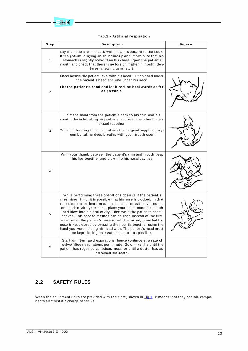
It is important to start mouth respiration at once and to call a doctor immediately. suggested procedurefor mouth to mouth respiration method is described in the Tab.1.
2.1.2 Treatment of burns
This treatment should be used after the patient has regained consciousness. It can also be employed whileartificial respiration is being applied (in this case there should be at least two persons present).
Warning
• Do not attempt to remove clothing from burnt sections
• Apply dry gauze on the burns
• Do not apply ointments or other oily substances.
ALS - MN.00183.E - 003 13
Tab.1 - Artificial respiration
2.2 SAFETY RULES
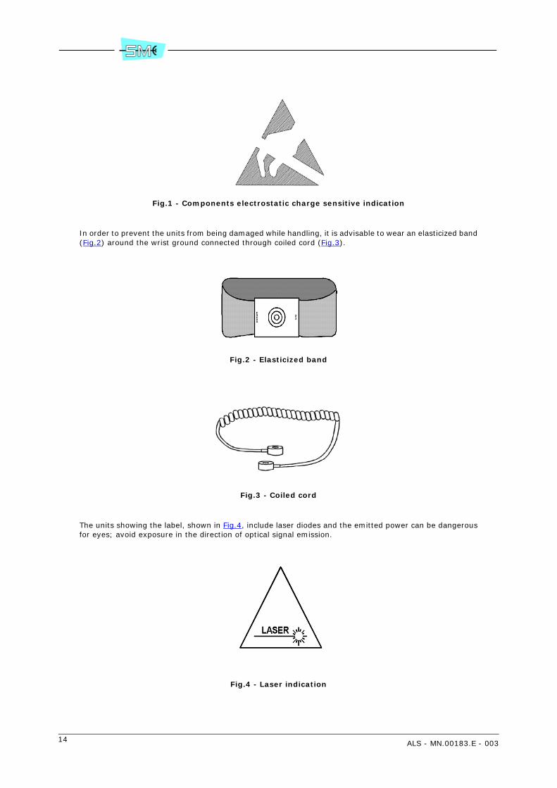
When the equipment units are provided with the plate, shown in Fig.1, it means that they contain compo-nents electrostatic charge sensitive.
Step Description Figure
1
Lay the patient on his back with his arms parallel to the body. If the patient is laying on an inclined plane, make sure that his
stomach is slightly lower than his chest. Open the patients mouth and check that there is no foreign matter in mouth (den-
tures, chewing gum, etc.).
2
Kneel beside the patient level with his head. Put an hand under the patient’s head and one under his neck.
Lift the patient’s head and let it recline backwards as far as possible.
3
Shift the hand from the patient’s neck to his chin and his mouth, the index along his jawbone, and keep the other fingers
closed together.
While performing these operations take a good supply of oxy-gen by taking deep breaths with your mouth open
4
With your thumb between the patient’s chin and mouth keep his lips together and blow into his nasal cavities
5
While performing these operations observe if the patient’s chest rises. If not it is possible that his nose is blocked: in that case open the patient’s mouth as much as possible by pressing on his chin with your hand, place your lips around his mouth and blow into his oral cavity. Observe if the patient’s chest heaves. This second method can be used instead of the first even when the patient’s nose is not obstructed, provided his
nose is kept closed by pressing the nostrils together using the hand you were holding his head with. The patient’s head must
be kept sloping backwards as much as possible.
6
Start with ten rapid expirations, hence continue at a rate of twelve/fifteen expirations per minute. Go on like this until the patient has regained conscious–ness, or until a doctor has as-
certained his death.
14 ALS - MN.00183.E - 003
Fig.1 - Components electrostatic charge sensitive indication
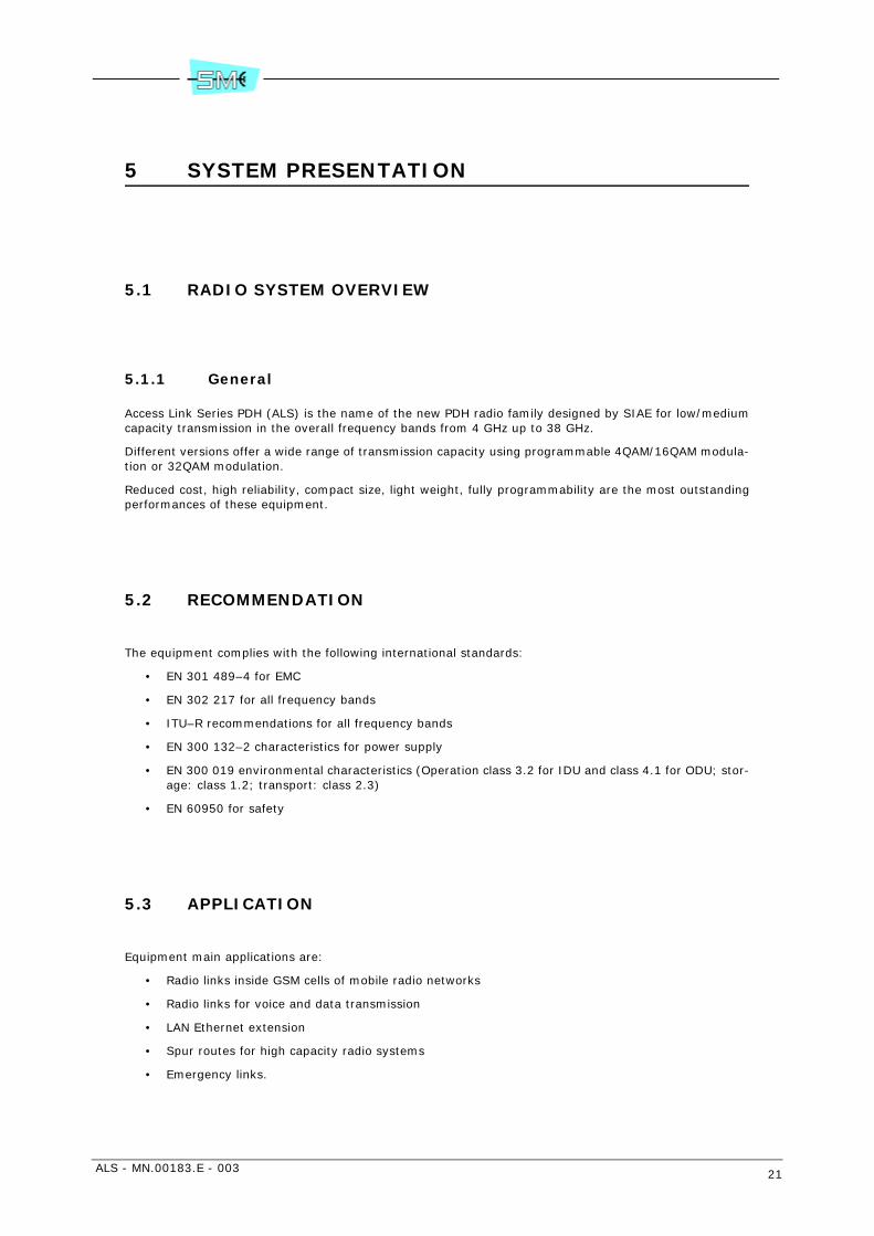
In order to prevent the units from being damaged while handling, it is advisable to wear an elasticized band(Fig.2) around the wrist ground connected through coiled cord (Fig.3).
Fig.2 - Elasticized band
Fig.3 - Coiled cord
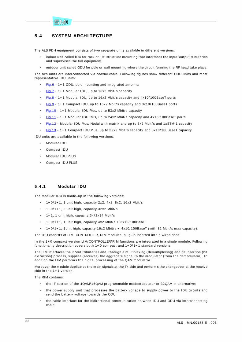
The units showing the label, shown in Fig.4, include laser diodes and the emitted power can be dangerousfor eyes; avoid exposure in the direction of optical signal emission.
Fig.4 - Laser indication

ALS - MN.00183.E - 003 15
2.3 CORRECT DISPOSAL OF THIS PRODUCT (Waste electrical & electronic equipment)
(Applicable in the European Union and other European countries with separate collection systems). Thismarking of Fig.5 shown on the product or its literature, indicates that it should not be disposed with otherhousehold wastes at the end of its working life. To prevent possible harm to the environment or humanhealth from uncontrolled waste disposal, please separate this from other types of wastes and recycle itresponsibly to promote the sustainable reuse of material resources. Household users should contact eitherthe retailer where they purchased this product, or their local government office, for details of where andhow they can take this item for environmentally safe recycling. Business users should contact their supplierand check the terms and conditions of the purchase contract. This product should not be mixed with othercommercial wastes for disposal.
Fig.5 - WEEE symbol - 2002/96/CE EN50419
2.4 INTERNAL BATTERY
Inside the equipment, in IDU unit, there is a lithium battery.
CAUTION: Risk of explosion if battery is replaced by an incorrect type. Dispose of used batteriesaccording to law.

16 ALS - MN.00183.E - 003
3 PURPOSE AND STRUCTURE OF THE MANUAL
3.1 PURPOSE OF THE MANUAL
The purpose of this manual consists in providing the user with information which permit to operate andmaintain the AL radio family.
Warning: This manual does not include information relevant to the SCT/LCT management program win-dows and relevant application. They will provided by the program itself as help-on line.
3.2 AUDIENCE BASIC KNOWLEDGE
The following knowledge and skills are required to operate the equipment:
• a basic understanding of microwave transmission
• installation and maintenance experience on digital radio system
• a good knowledge of IP/OSI networks and routing policy.
3.3 STRUCTURE OF THE MANUAL
The manual is subdivided into sections each of them developing a specific topic entitling the section.
Each section consists of a set of chapters, enlarging the main subject master.
Section 1 – User Guide
It provides the information about the main safety rules and expounds the purpose and the structure of themanual.
Section 2 – Description and specifications
It traces the broad line of equipment operation and lists the main technical characteristics of the wholeequipment and units it consists of.
List of abbreviation meaning is also supplied.
Section 3 – Installation
The mechanical installation procedures are herein set down as well as the user electrical connections.
The content of the tool kit (if supplied) is also listed.

ALS - MN.00183.E - 003 17
Section 4 – Line–Up
Line–up procedures are described as well as checks to be carried out for the equipment correct operation.The list of the instruments to be used and their characteristics are also set down.
Section 5 – Maintenance
The routine maintenance actions are described as well as fault location procedures in order to identify thefaulty unit and to re–establish the operation after its replacement with a spare one.
Section 6 – Programming and supervision
The AL radio family is programmed and supervised using different software tools. Some of them are al-ready available, some other will be available in the future.
This section lists the tools implemented and indicates if descriptions are already available.
Each description of software tools is supplied in a separated manual.
Section 7 – Composition
Position, part numbers of the components the equipment consist of, are shown in this section.
Section 8 – Lists and assistance
This section contains the lists of figures and tables and the assistance service information.

18 ALS - MN.00183.E - 003

ALS - MN.00183.E - 003 19
Section 2.DESCRIPTIONS AND SPECIFI-CATION
4 ABBREVIATION LIST
4.1 LIST OF ABBREVIATIONS
- AF Assured Forwarding
- AL Access Link
- ALS Access LInk Series
- AIS Alarm Indication Signal
- ATPC Automaric Transmit Power Control
- BB Baseband
- BBER Background Block Error Radio
- BER Bit Error Rate
- DSCP Differentiated Service Code Point
- DSP Digital Signal Processing
- E1 2 Mbit/s
- EMC/EMI Electromagnetic Compatibility/Electromagnetic Interference
- EOC Embedded Overhead Channel
- ERC European Radiocommunication Committee
- ESD Electrostatic Discharge
- FEC Forward Error Corrector
- FEM Fast Ethernet Module
- HDLC High Level Data Link Control
- IDU Indoor Unit

20 ALS - MN.00183.E - 003
- IF Intermediate Frequency
- IpToS Type of Service IP
- LAN Local Area Network
- LAPS Link Access Procedure SDH
- LCT Local Craft Terminal
- LIM Line Interface Module
- LLF Link Loss Forwarding
- LOF Loss Of Frame
- LOS Loss Of Signal
- MAC Media Access Control
- MDI Medium Dependent Interface
- MDIX Medium Dependent Interface Crossover
- MIB Management Information Base
- MMIC Monolitic Microwave Integrated Circuit
- MTBF Mean Time Between Failure
- NE Network Element
- ODU Outdoor Unit
- OSI Open System Interconnection
- PDH Plesiochronous Digital Hierarchy
- PPI Plesiochronous Physical Interface
- PPP Point to Point Protocol
- PTOS Priority Type Of Service
- RIM Radio Interface Module
- SCT Subnetwork Craft Terminal
- SNMP Simple Network Management Protocol
- TCP/IP Transmission Control Protocol/Internet Protocol
- TOS Type Of Service
- VID Virtual LAN Identifier
- VLAN Virtual LAN
- WFQ Wait Fair Queue
- Wayside Traffic Additional 2 Mbit/s Traffic
ALS - MN.00183.E - 003 21
5 SYSTEM PRESENTATION
5.1 RADIO SYSTEM OVERVIEW
5.1.1 General
Access Link Series PDH (ALS) is the name of the new PDH radio family designed by SIAE for low/mediumcapacity transmission in the overall frequency bands from 4 GHz up to 38 GHz.
Different versions offer a wide range of transmission capacity using programmable 4QAM/16QAM modula-tion or 32QAM modulation.
Reduced cost, high reliability, compact size, light weight, fully programmability are the most outstandingperformances of these equipment.
5.2 RECOMMENDATION
The equipment complies with the following international standards:
• EN 301 489–4 for EMC
• EN 302 217 for all frequency bands
• ITU–R recommendations for all frequency bands
• EN 300 132–2 characteristics for power supply
• EN 300 019 environmental characteristics (Operation class 3.2 for IDU and class 4.1 for ODU; stor-age: class 1.2; transport: class 2.3)
• EN 60950 for safety
5.3 APPLICATION
Equipment main applications are:
• Radio links inside GSM cells of mobile radio networks
• Radio links for voice and data transmission
• LAN Ethernet extension
• Spur routes for high capacity radio systems
• Emergency links.
22 ALS - MN.00183.E - 003
5.4 SYSTEM ARCHITECTURE
The ALS PDH equipment consists of two separate units available in different versions:
• indoor unit called IDU for rack or 19” structure mounting that interfaces the input/output tributariesand supervises the full equipment
• outdoor unit called ODU for pole or wall mounting where the circuit forming the RF head take place.
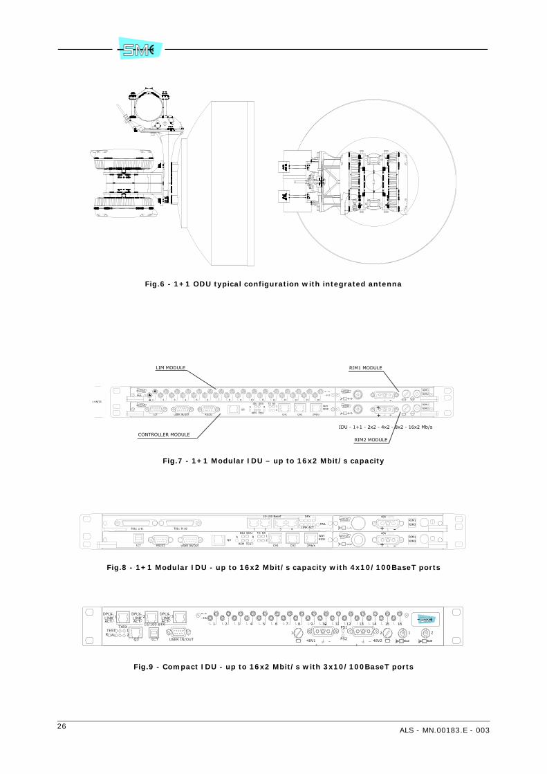
The two units are interconnected via coaxial cable. Following figures show different ODU units and mostrepresentative IDU units:
• Fig.6 - 1+1 ODU, pole mounting and integrated antenna
• Fig.7 - 1+1 Modular IDU, up to 16x2 Mbit/s capacity
• Fig.8 - 1+1 Modular IDU, up to 16x2 Mbit/s capacity and 4x10/100BaseT ports
• Fig.9 - 1+1 Compact IDU, up to 16x2 Mbit/s capacity and 3x10/100BaseT ports
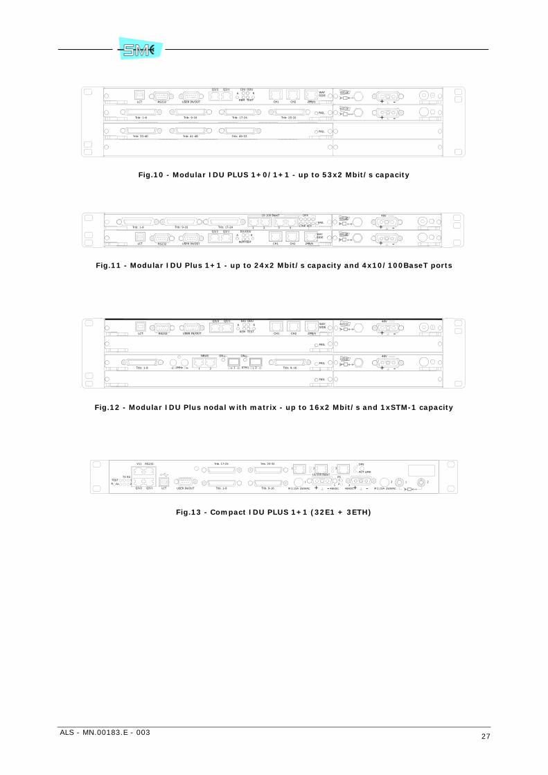
• Fig.10 - 1+1 Modular IDU Plus, up to 53x2 Mbit/s capacity
• Fig.11 - 1+1 Modular IDU Plus, up to 24x2 Mbit/s capacity and 4x10/100BaseT ports
• Fig.12 - Modular IDU Plus, Nodal with matrix and up to 8x2 Mbit/s and 1xSTM-1 capacity
• Fig.13 - 1+1 Compact IDU Plus, up to 32x2 Mbit/s capacity and 3x10/100BaseT capacity
IDU units are available in the following versions:
• Modular IDU
• Compact IDU
• Modular IDU PLUS
• Compact IDU PLUS.
5.4.1 Modular IDU
The Modular IDU is made–up in the following versions:
• 1+0/1+1, 1 unit high, capacity 2x2, 4x2, 8x2, 16x2 Mbit/s
• 1+0/1+1, 2 unit high, capacity 32x2 Mbit/s
• 1+1, 1 unit high, capacity 34/2x34 Mbit/s
• 1+0/1+1, 1 unit high, capacity 4x2 Mbit/s + 3x10/100BaseT
• 1+0/1+1, 1unit high, capacity 16x2 Mbit/s + 4x10/100BaseT (with 32 Mbit/s max capacity).
The IDU consists of LIM, CONTROLLER, RIM modules, plug–in inserted into a wired shelf.
In the 1+0 compact version LIM/CONTROLLER/RIM functions are integrated in a single module. Followingfunctionality description covers both 1+0 compact and 1+0/1+1 standard versions.
The LIM interfaces the in/out tributaries and, through a multiplexing (demultiplexing) and bit insertion (bitextraction) process, supplies (receives) the aggregate signal to the modulator (from the demodulator). Inaddition the LIM performs the digital processing of the QAM modulator.
Moreover the module duplicates the main signals at the Tx side and performs the changeover at the receiveside in the 1+1 version.
The RIM contains:
• the IF section of the 4QAM/16QAM programmable modemodulator or 32QAM in alternative;
• the power supply unit that processes the battery voltage to supply power to the IDU circuits andsend the battery voltage towards the ODU;
• the cable interface for the bidirectional communication between IDU and ODU via interconnectingcable.

ALS - MN.00183.E - 003 23
The Controller performs the following:
• interfaces the service signals as 1x9600 bit/s or 2x4800 bit/s, 64 kbit/s, 2 Mbit/s (details are givenin the system technical specification)
• contains the equipment software that permits to control and to manage all the equipment function-ality through a main controller and associated peripherals distributed within IDU and ODU
• interfaces the SCT/LCT management system through Ethernet, RS232 and USB ports
• receive external alarms and route them to relay contact along with the internal alarms generatedby the equipment.
5.4.2 Compact IDU unit
The Compact IDU unit is available in the following versions:
• 1 unit, 1+0, 2/4/8xE1
• 1 unit, 1+0, 2/4/8/16xE1
• 1 unit, 1+1, 2/4/8xE1
• 1 unit, 1+1, 2/4/8/16xE1
• 1 unit, 1+0, 2/4/8xE1 + 3ETH
• 1 unit, 1+1, 2/4/8xE1 + 3ETH
• 1 unit, 1+1, 16xE1 + 3ETH.
The Ethernet module V12252 can be housed inside the IDU, as option, for the Ethernet traffic. The compactIDUs are made by a single card plugged into a cabled rack.
The line interfaces contain the connections of the tributaries and, by means of processes of multiplexing/demultiplexing and of bit insertion/extraction, provide/receive the aggregate signal to/from the modulator/demodulator. The line interfaces realize the digital processing for the QAM modulator and, in 1+1 config-uration, duplicate the main signals on the transmission side and execute the switch on the reception side.The interfaces to the ODU contain the interface of the cable for the bidirectional communication betweenODU and IDU, and implement the IF section of the mo-demodulator. The power supply units of the IDUprocess the battery voltage and supply power to the circuits of IDU and ODU. The controller section of theradio contains the interfaces of the service channels, stores the firmware of the IDU, interfaces the SIAEmanagement systems through dedicated supervision ports and forwards external and internal alarms tothe relay contacts.
5.4.3 Modular IDU Plus
The Modular IDU Plus is made up of the following versions:
• terminal 1+0 and 1+1, 2/4/5/8/10/16/21/32xE1 capacity, 1 unit high
• terminal 1+0 and 1+1, 2/4/5/8/10/16/21/32/42/53xE1 capacity, 2 unit high
• terminal 1+0 and 1+1, 2/4/5/8/10/16/21/24xE1 + 4x10/100BaseT, 1 unit high
• drop-insert 1+0, 1+1, 4x(1+0), up to 4x53xE1 capacity, that is passthrough up to 212xE1 streamsplus drop-insert up to 32xE1 or up to 53xE1 or up to 79xE1 with STM1+16xE1 interface, equippedwith matrix into 2 units
• nodal, up to 3xModular IDU Plus can be joined in a mode giving full switching capabilities to all theE1 streams coming from max 12 directions. Any direction can contain max 53xE1.
1 unit Modular IDU Plus consists of LIM 32E1, Eq. Controller, RIM plug-in inserted into a wired shelf.
2 unit Modular IDU Plus consists of Eq. Controller modules, LIM 32E1 or Matrix with 32E1, or Matrix withSTM1 and 16E1, one Processor for two ODU.

24 ALS - MN.00183.E - 003
The LIM module interfaces the in/out tributaries and, through a multiplexing (demultiplexing) and bit in-sertion (bit extraction) process, supplies (receives) the aggregate signal to the modulator (from the de-modulator). In addition the LIM performs the digital processing of the QAM modulator and duplicates themain signals at the Tx side and performs the changeover at the receive side in the 1+1 version.
The Matrix and the processor perform LIM Plus drop/insert of each E1 stream coming from/to 4 directions(12 direction for a Nodal configuration).
The RIM contains:
• the IF section of the 4QAM/16QAM programmable modemodulator or 32QAM;
• the power supply unit that processes the battery voltage to supply power to the IDU circuits andsend the battery voltage towards the ODU
• the cable interface for the bidirectional communication between IDU and ODU via interconnectingcable.
The Controller performs the following:
• interfaces the service signals as 1x9600 bit/s or 2x4800 bit/s, 64 kbit/s, E1 WS (details are givenin the system technical specification)
• contains the equipment software that permits to control and to manage all the equipment function-ality through a main controller and associated peripherals distributed within IDU and ODU
• interfaces the SCT/LCT management system through Ethernet, RS232 and USB ports
• receive external alarms and route them to relay contact along with the internal alarms generatedby the equipment.
5.4.4 IDU Plus Compact Unit (5.4.4)
The IDU Plus Compact unit is available in the following hardware versions:
• 1 unit for IDU Plus compact rack, configuration 1+0, 2/4/8/16/32xE1 + 3ETH
• 1 unit for IDU Plus compact rack, configuration 1+1, 2/4/8/16/32xE1 + 3ETH
The compact IDU Plus are made by a single card.
The line interfaces contain the connections of the tributaries and, by means of processes of multiplexing/demultiplexing and of bit insertion/extraction, provide/receive the aggregate signal to/from the modulator/demodulator. The line interfaces realize the digital processing for the QAM modulator and, in 1+1 config-uration, duplicate the main signals on the transmission side and execute the switch on the reception side.The interfaces to the ODU contain the interface of the cable for the bidirectional communication betweenODU and IDU, and implement the IF section of the mo-demodulator. The power supply units of the IDUprocess the battery voltage and supply power to the circuits of IDU and ODU. The controller section of theradio contains the interfaces of the service channels, stores the firmware of the IDU, interfaces the SIAEmanagement systems through dedicated supervision ports and forwards external and internal alarms tothe relay contacts.
5.4.5 ODU
The ODU unit contains circuits that permit to interface from one side the IDU and the antenna from theother side.
The QAM modulated carrier is shifted to RF frequency bands through a double conversion.
Similarly it occurs at the receive side to send the IF converted carrier to the demodulator within the IDU.
The ODU unit is available in two different versions: AL and AS.
The ODU AS is also called “Universal” because it can be used as SDH ODU in Siae ALS (SIAE SDH link fam-ily).
Antenna coupling is performed through a balanced or unbalanced hybrid system.

ALS - MN.00183.E - 003 25
5.5 MANAGEMENT SYSTEM
AL different equipment can be locally and remotely controlled via a dedicated application software calledSCT/LCT running on PC.
It provides a friendly graphic interface complying with current standard use of keyboard, mouse, windowsand so on.
5.5.1 Hardware platform
The hardware platform used by SCT/LCT is based on personal computer having at least following charac-teristics:
• microprocessor Pentium 133 MHz
• 32 Mbyte RAM
• windows compatible graphic monitor
• floppy drive 1.44 Mb
• HD with 50 Mbyte of free space
• Windows 95/Windows NT/Windows 98/Windows 2000/Windows XP.
5.5.2 Management ports
The SCT/LCT program is connected to the equipment via the following communication ports:
• Q3 (Ethernet LAN 10BaseT)
• RS232 (asynchronous serial line)
• LCT (USB)
• Embedded Overhead Channel (EOC) embedded into the radio frame.
• Embedded Overhead Channel (EOC) embedded into a 16 kbit/s or 4x16 kbit/s time slot of one ofthe 2 Mbit/s tributary signals.
5.5.3 Protocols
SNMP along with IP or OSI protocol stacks are used to reach and manage the equipment operation.
26 ALS - MN.00183.E - 003
Fig.6 - 1+1 ODU typical configuration with integrated antenna
Fig.7 - 1+1 Modular IDU – up to 16x2 Mbit/s capacity
Fig.8 - 1+1 Modular IDU - up to 16x2 Mbit/s capacity with 4x10/100BaseT ports
Fig.9 - Compact IDU - up to 16x2 Mbit/s with 3x10/100BaseT ports
IDU - 1+1 - 2x2 - 4x2 - 8x2 - 16x2 Mb/s
16151413121110987654321
FAIL
1 UNITA'
-
++
-RIM
RIM
1
2
2
1
RIM
RIM
Q3
USER IN/OUT
WAYA
LCT RS232 CH1 CH2 2Mb/s
SIDE2
1RXTX
REM TEST
ODUIDU
R
CONTROLLER MODULERIM2 MODULE
LIM MODULE RIM1 MODULE
Q3WAYA
LCT USER IN/OUTRS232 CH1 CH2 2Mb/s
SIDE21
RXTX
REM TEST
ODUIDUR RIM
RIM
1
2
+ -
-+
2
1
RIM
RIM48V
48V
10-100 BaseT
4321LINK ACT
DPX
FAIL
Trib: 9-16Trib: 1-8
10/100 BTX
321ACTLINK
DPLXDPLXLINKACTACT
LINKDPLX
21
RXTX
ALTESTR
PS2
PS12121
48V2
+ ––+
48V1Q3 LCT USER IN/OUT
1 2 3 4 5 6 7 8 9 10 11 12 13 14 15 16
ALS - MN.00183.E - 003 27
Fig.10 - Modular IDU PLUS 1+0/1+1 - up to 53x2 Mbit/s capacity
Fig.11 - Modular IDU Plus 1+1 - up to 24x2 Mbit/s capacity and 4x10/100BaseT ports
Fig.12 - Modular IDU Plus nodal with matrix - up to 16x2 Mbit/s and 1xSTM-1 capacity
Fig.13 - Compact IDU PLUS 1+1 (32E1 + 3ETH)
FAIL
Trib: 1-8 Trib: 9-16 Trib: 17-24 Trib: 25-32
Q3/2WAYA
LCT USER IN/OUTRS232 CH1 CH2 2Mb/s
SIDE
REM TEST
ODUIDUR
Q3/1
+ -
-+
FAIL
Trib: 33-40 Trib: 41-48 Trib: 49-53
Trib: 1-8 Trib: 9-16
FAIL
DPX
ACTLINK1 2 3 4
10-100 BaseT
Trib: 17-24
+ -
-+
48V
Q3/1R
IDUODU
TESTREM
SIDE
2Mb/sCH2CH1RS232 USER IN/OUTLCT
A WAYQ3/2
Q3/1R
IDU ODU
TESTREM
SIDE
2Mb/sCH2CH1RS232 USER IN/OUTLCT
A WAYQ3/2
48V
48V
-++ -
FAIL
FAIL
21
NBUS
21
FAIL
Trib: 1-8 Trib: 9-16
ON ON
STM12MHz
1
12 2
RS232V11
Q3/2 Q3/1 LCT USER IN/OUT
RXTX12
TESTALR
Trib. 1-8 Trib. 9-16
Trib. 25-32Trib. 17-24
21
+ - -+48VDC 48VDC
PS
1 2
250VACM 3.15A3.15AM 250VAC
10/100 BaseT
1 2 3ACT LINK
DPX

28 ALS - MN.00183.E - 003
6 EQUIPMENT TECHNICAL SPECIFICATIONS
6.1 TECHNICAL SPECIFICATIONS
- Frequency range see attachment
- RF channelling see attachment
- Go–return frequency see attachment
- Antenna configuration see attachment
- Frequency stability see attachment
- Spurious transmission see attachment
- Modulation see attachment
- Demodulation Coherent
- Output power see attachment
- Rx threshold see attachment
- Additional losses in Tx and Rx for 1+1 version see attachment
- BER see attachment
- Max RF level in Rx for BER10-3 see attachment
- Power supply see attachment
- Consumption see attachment
6.2 SERVICE CHANNELS
- Capacity of the service channels in the Modular IDU.
The following service channels are available for each type of configuration:
• version 1+0/1+1 - 2x2, 4x2, 8x2, 16x2, 34, 2x34 Mbit/s (1 unit)
Three service channels available subdivided as follows:
- interface V28 data channel 1x9600 with digital party line or 2x4800 baud or data channel sync./async. RS232C 9600 baud
- co/contradirectional interface V11 64 kbit/s
- 2 Mbit/s wayside interface for capacities greater or equal to 16x2 Mbit/s
• version 1+0/1+1 high capacity - 32x2 Mbit/s (2 units)
Three service channels:
- interface V28 data channel 1x9600 baud with digital party line or 2x4800 baud or data channelsyncr./async. RS232C 9600 baud
- V11 co/contradirectional 64 kbit/s interface
- 2 Mbit/s wayside interface for capacities greater than 16xE1
ALS - MN.00183.E - 003 29
• version 1+0/1+1 AL Ethernet 100 Mbit/s Modular (1 unit)
Three service channels:
- interface V.28 data channel 1x9600 baud with digital party or 2x4800 baud or data channelsync./async. RS232C 9600 baud
- 2 x interfaces 2 Mbit/s wayside available on LIM as tributary 3 and 4.
- Capacity of the (optional) service channels in the IDU Compact
The following capacity of the service channel is available
• 1+0/1+1 - version 2x2, 4x2, 8x2, 16x2 Mbit/s (1 unit)
One service channel is available: interface 64 kbit/s V11 co/contradirectional
• 1+0/1+1 version 3xEthernet + 16x2 Mbit/s, no service channel
- Capacity of the service channel in the Modular IDU Plus
Three service channels are available:
- interface V28 data channel 1x9600 baud with digital party line or 2x4800 or synchronous (orasynchronous) data channel
- V11 64 kbit/s contradirectional or 64 kbit/s codirectional interface
- 2 Mbit/s wayside interface for capacities greater or equal to 16xE1 (only for hierarchic capaci-ties).
- Capacities of the service channels for the IDU Compact Plus
Two service channels are available:
• V11 and RS232
- V11 or, in alternative, V28 interface; V11 64 kbit/s contradirectional or codirectional interface;interface V28 data channel 1x9600 baud with digital party line or 2x4800 baud or V.24 9600baud synchronous (or asynchronous) data channel
- RS232 PPP interface for forwarding of the supervision signal
• an additional external EOW module is available, connected to the IDU Compact Plus to the portsV11 and RS232.
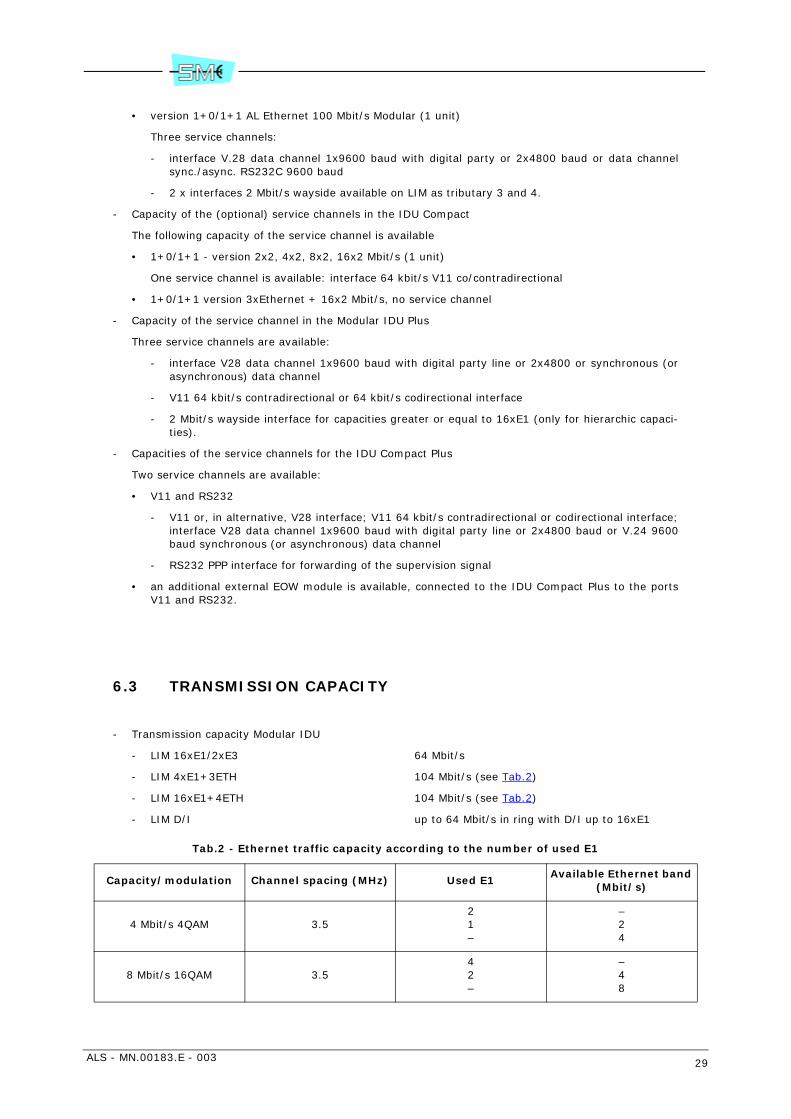
6.3 TRANSMISSION CAPACITY
- Transmission capacity Modular IDU
- LIM 16xE1/2xE3 64 Mbit/s
- LIM 4xE1+3ETH 104 Mbit/s (see Tab.2)
- LIM 16xE1+4ETH 104 Mbit/s (see Tab.2)
- LIM D/I up to 64 Mbit/s in ring with D/I up to 16xE1
Tab.2 - Ethernet traffic capacity according to the number of used E1
Capacity/modulation Channel spacing (MHz) Used E1Available Ethernet band
(Mbit/s)
4 Mbit/s 4QAM 3.521–
–24
8 Mbit/s 16QAM 3.542–
–48
30 ALS - MN.00183.E - 003
- Transmission capacity Compact IDU
- Compact IDU up to 16xE1 32 Mbit/s
- Compact IDU up to 16xE1+3ETH 64 Mbit/s
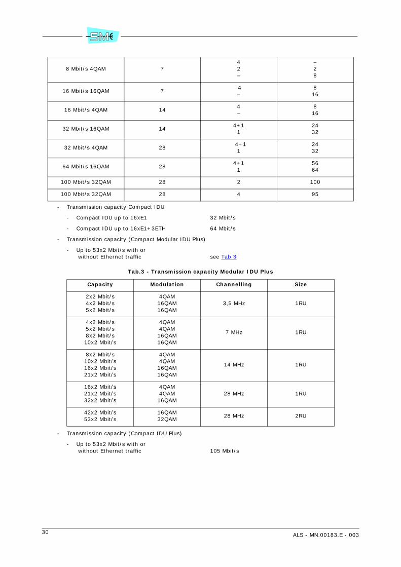
- Transmission capacity (Compact Modular IDU Plus)
- Up to 53x2 Mbit/s with or without Ethernet traffic see Tab.3
Tab.3 - Transmission capacity Modular IDU Plus
- Transmission capacity (Compact IDU Plus)
- Up to 53x2 Mbit/s with or without Ethernet traffic 105 Mbit/s
8 Mbit/s 4QAM 742–
–28
16 Mbit/s 16QAM 7 4–
816
16 Mbit/s 4QAM 144–
816
32 Mbit/s 16QAM 144+1
12432
32 Mbit/s 4QAM 28 4+1
12432
64 Mbit/s 16QAM 284+1
15664
100 Mbit/s 32QAM 28 2 100
100 Mbit/s 32QAM 28 4 95
Capacity Modulation Channelling Size
2x2 Mbit/s4x2 Mbit/s5x2 Mbit/s
4QAM16QAM16QAM
3,5 MHz 1RU
4x2 Mbit/s5x2 Mbit/s8x2 Mbit/s10x2 Mbit/s
4QAM4QAM16QAM16QAM
7 MHz 1RU
8x2 Mbit/s10x2 Mbit/s16x2 Mbit/s21x2 Mbit/s
4QAM4QAM16QAM16QAM
14 MHz 1RU
16x2 Mbit/s21x2 Mbit/s32x2 Mbit/s
4QAM4QAM16QAM
28 MHz 1RU
42x2 Mbit/s53x2 Mbit/s
16QAM32QAM
28 MHz 2RU
ALS - MN.00183.E - 003 31
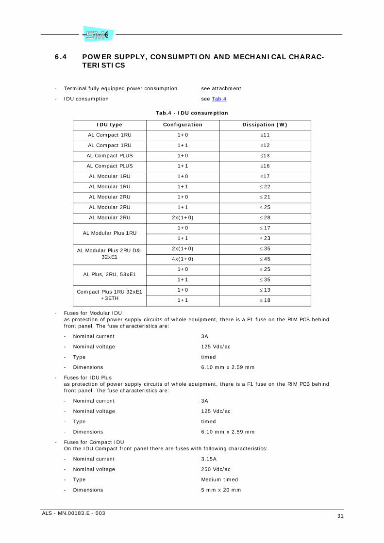
6.4 POWER SUPPLY, CONSUMPTION AND MECHANICAL CHARAC-TERISTICS
- Terminal fully equipped power consumption see attachment
- IDU consumption see Tab.4
Tab.4 - IDU consumption
- Fuses for Modular IDUas protection of power supply circuits of whole equipment, there is a F1 fuse on the RIM PCB behindfront panel. The fuse characteristics are:
- Nominal current 3A
- Nominal voltage 125 Vdc/ac
- Type timed
- Dimensions 6.10 mm x 2.59 mm
- Fuses for IDU Plusas protection of power supply circuits of whole equipment, there is a F1 fuse on the RIM PCB behindfront panel. The fuse characteristics are:
- Nominal current 3A
- Nominal voltage 125 Vdc/ac
- Type timed
- Dimensions 6.10 mm x 2.59 mm
- Fuses for Compact IDUOn the IDU Compact front panel there are fuses with following characteristics:
- Nominal current 3.15A
- Nominal voltage 250 Vdc/ac
- Type Medium timed
- Dimensions 5 mm x 20 mm
IDU type Configuration Dissipation (W)
AL Compact 1RU 1+0 ≤11
AL Compact 1RU 1+1 ≤12
AL Compact PLUS 1+0 ≤13
AL Compact PLUS 1+1 ≤16
AL Modular 1RU 1+0 ≤17
AL Modular 1RU 1+1 ≤ 22
AL Modular 2RU 1+0 ≤ 21
AL Modular 2RU 1+1 ≤ 25
AL Modular 2RU 2x(1+0) ≤ 28
AL Modular Plus 1RU1+0 ≤ 17
1+1 ≤ 23
AL Modular Plus 2RU D&I 32xE1
2x(1+0) ≤ 35
4x(1+0) ≤ 45
AL Plus, 2RU, 53xE11+0 ≤ 25
1+1 ≤ 35
Compact Plus 1RU 32xE1 +3ETH
1+0 ≤ 13
1+1 ≤ 18
32 ALS - MN.00183.E - 003
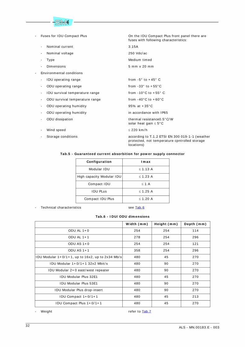
- Fuses for IDU Compact Plus On the IDU Compact Plus front panel there arefuses with following characteristics:
- Nominal current 3.15A
- Nominal voltage 250 Vdc/ac
- Type Medium timed
- Dimensions 5 mm x 20 mm
- Environmental conditions
- IDU operating range from -5° to +45° C
- ODU operating range from -33° to +55°C
- IDU survival temperature range from -10°C to +55° C
- ODU survival temperature range from -40°C to +60°C
- ODU operating humidity 95% at +35°C
- ODU operating humidity in accordance with IP65
- ODU dissipation thermal resistance0.5°C/Wsolar heat gain ≤ 5°C
- Wind speed ≤ 220 km/h
- Storage conditions according to T.1.2 ETSI EN 300 019-1-1 (weatherprotected, not temperature cpntrolled storage locations)
Tab.5 - Guaranteed current absorbition for power supply connector
- Technical characteristics see Tab.6
Tab.6 - IDU/ODU dimensions
- Weight refer to Tab.7
Configuration Imax
Modular IDU ≤ 1.13 A
High capacity Modular IDU ≤ 1.23 A
Compact IDU ≤ 1 A
IDU PLus ≤ 1.25 A
Compact IDU Plus ≤ 1.20 A
Width (mm) Height (mm) Depth (mm)
ODU AL 1+0 254 254 114
ODU AL 1+1 278 254 296
ODU AS 1+0 254 254 121
ODU AS 1+1 358 254 296
IDU Modular 1+0/1+1, up to 16x2, up to 2x34 Mb/s 480 45 270
IDU Modular 1+0/1+1 32x2 Mbit/s 480 90 270
IDU Modular 2+0 east/west repeater 480 90 270
IDU Modular Plus 32E1 480 45 270
IDU Modular Plus 53E1 480 90 270
IDU Modular Plus drop-insert 480 90 270
IDU Compact 1+0/1+1 480 45 213
IDU Compact Plus 1+0/1+1 480 45 270
ALS - MN.00183.E - 003 33
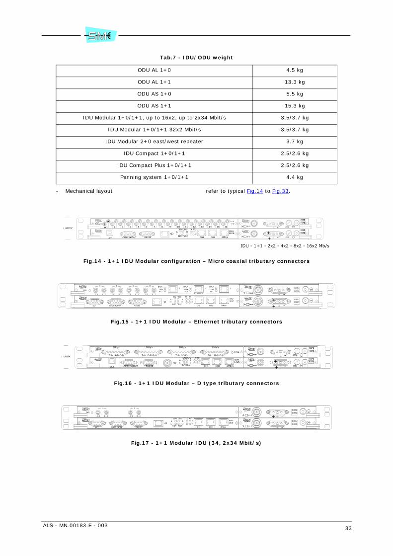
Tab.7 - IDU/ODU weight
- Mechanical layout refer to typical Fig.14 to Fig.33.
Fig.14 - 1+1 IDU Modular configuration – Micro coaxial tributary connectors
Fig.15 - 1+1 IDU Modular – Ethernet tributary connectors
Fig.16 - 1+1 IDU Modular – D type tributary connectors
Fig.17 - 1+1 Modular IDU (34, 2x34 Mbit/s)
ODU AL 1+0 4.5 kg
ODU AL 1+1 13.3 kg
ODU AS 1+0 5.5 kg
ODU AS 1+1 15.3 kg
IDU Modular 1+0/1+1, up to 16x2, up to 2x34 Mbit/s 3.5/3.7 kg
IDU Modular 1+0/1+1 32x2 Mbit/s 3.5/3.7 kg
IDU Modular 2+0 east/west repeater 3.7 kg
IDU Compact 1+0/1+1 2.5/2.6 kg
IDU Compact Plus 1+0/1+1 2.5/2.6 kg
Panning system 1+0/1+1 4.4 kg
IDU - 1+1 - 2x2 - 4x2 - 8x2 - 16x2 Mb/s
16151413121110987654321FAIL
1 UNITA'
-++
-RIMRIM
12
21
RIMRIM
Q3
USER IN/OUT
WAYA
LCT RS232 CH1 CH2 2Mb/s
SIDE21
RXTX
REMTEST
ODUIDUR
R
IDU ODU
TESTREM
TX RX1
2 SIDE
2Mb/sCH2CH1
Q3
RS232LCT
A WAY
USER IN/OUT
DCBA
FAIL
10/100 BTX
1 2 3
ACTLINK
DPLX
ACTLINK
DPLX
ACTLINK
DPLX
-+ 2
1
RIM
RIM
RIM
RIM
1
2
+
-
1 UNITA'
RIMRIM
12
21
RIMRIM
-++ -
Trib: M-N-O-PTrib: I-J-K-LTrib: E-F-G-H
2Mb/s2Mb/s2Mb/s2Mb/s
Trib: A-B-C-D
FAIL
RIDUODU
TESTREM
TXRX12 SIDE
2Mb/sCH2CH1Q3
RS232USER IN/OUT
A WAY
LCT
21
FAIL
Q3
USER IN/OUT
WAYA
LCT RS232 CH1 CH2 2Mb/s
SIDE2
1RXTX
REM TEST
ODUIDU
R RIM
RIM
1
2
+
-
-
+
2
1
RIM
RIM
34 ALS - MN.00183.E - 003
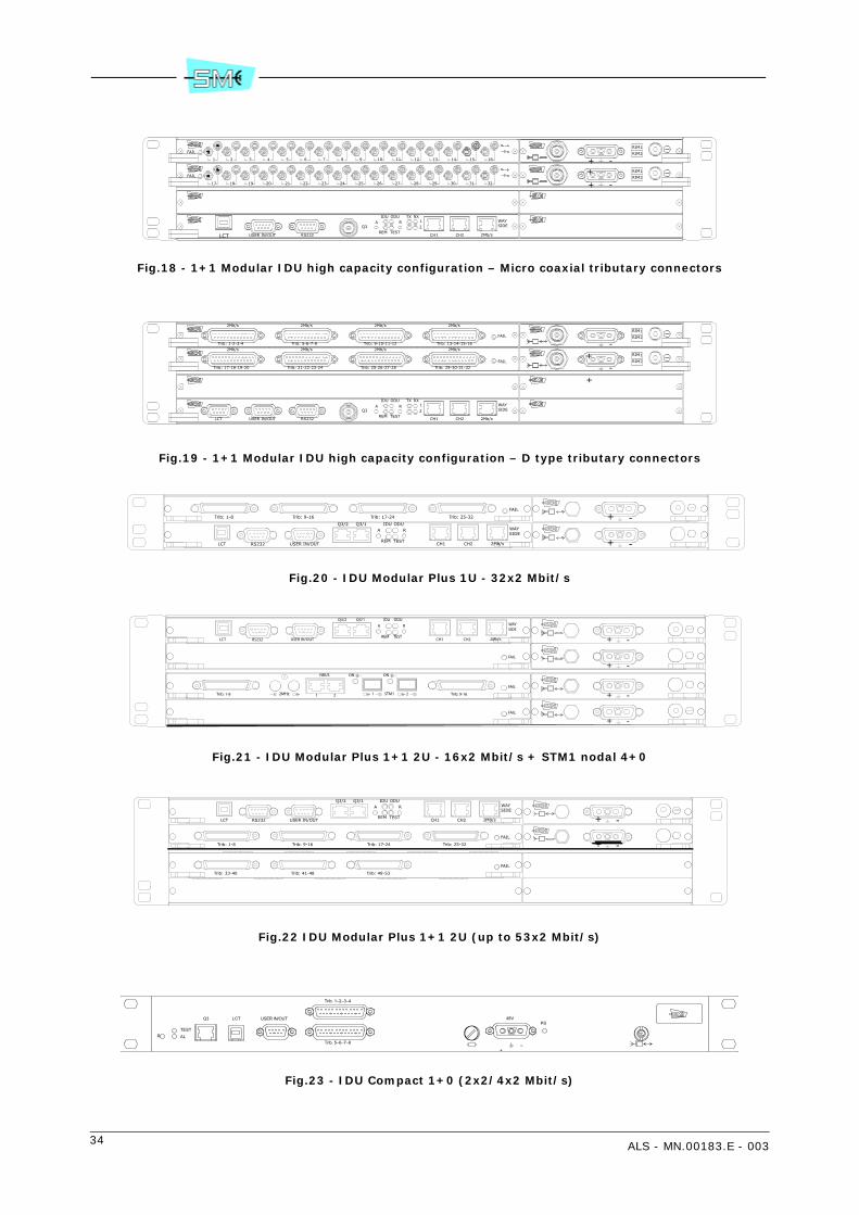
Fig.18 - 1+1 Modular IDU high capacity configuration – Micro coaxial tributary connectors
Fig.19 - 1+1 Modular IDU high capacity configuration – D type tributary connectors
Fig.20 - IDU Modular Plus 1U - 32x2 Mbit/s
Fig.21 - IDU Modular Plus 1+1 2U - 16x2 Mbit/s + STM1 nodal 4+0
Fig.22 IDU Modular Plus 1+1 2U (up to 53x2 Mbit/s)
Fig.23 - IDU Compact 1+0 (2x2/4x2 Mbit/s)
FAIL
1 2 3 4 5 6 7 8 9 10 11 12 13 14 15 16
FAIL
17 18 19 20 21 22 23 24 25 26 27 28 29 30 31 32
RIM
RIM
1
2+
-
-
+
2
1
RIM
RIM
WAYA
USER IN/OUT RS232 CH1 CH2 2Mb/s
SIDE21
RXTX
REM TEST
ODUIDUR
Q3
+
LCT
RIM
RIM
1
2
+
-
-
+
2
1
RIM
RIM
2Mb/s2Mb/s2Mb/s2Mb/s
FAIL
Trib: 13-14-15-16Trib: 9-10-11-12Trib: 1-2-3-4 Trib: 5-6-7-8
Trib: 29-30-31-32Trib: 25-26-27-28Trib: 21-22-23-24Trib: 17-18-19-20
2Mb/s 2Mb/s 2Mb/s 2Mb/s
FAIL
Q3R
IDU ODU
TESTREM
TX RX12 SIDE
2Mb/sCH2CH1RS232USER IN/OUTLCT
A WAY
+ -
-+
Q3/1R
IDU ODU
TESTREM
SIDE
2Mb/sCH2CH1RS232 USER IN/OUTLCT
A WAYQ3/2
FAIL
Trib: 1-8 Trib: 9-16 Trib: 17-24 Trib: 25-32
Q3/1R
IDU ODU
TESTREM
SIDE
2Mb/sCH2CH1RS232 USER IN/OUTLCT
A WAYQ3/2
+ -
-++ -
-+
FAIL
FAIL
21
NBUS
21
FAIL
Trib: 1-8 Trib: 9-16
ON ON
STM12MHz
FAIL
Trib: 1-8 Trib: 9-16 Trib: 17-24 Trib: 25-32
Q3/2WAYA
LCT USER IN/OUTRS232 CH1 CH2 2Mb/s
SIDE
REM TEST
ODUIDUR
Q3/1
+ -
-+
FAIL
Trib: 33-40 Trib: 41-48 Trib: 49-53
48V
+ –
Trib. 1–2–3–4
Trib. 5–6–7–8
PSLCTQ3 USER IN/OUT
RTESTAL
ALS - MN.00183.E - 003 35
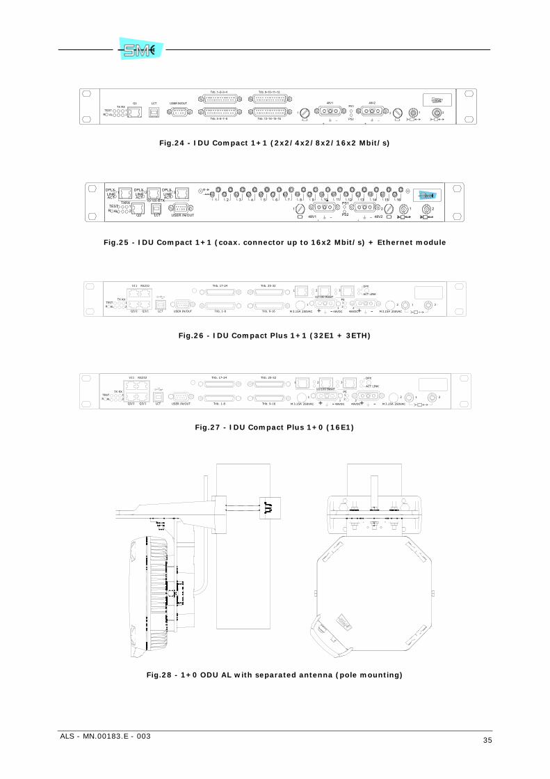
Fig.24 - IDU Compact 1+1 (2x2/4x2/8x2/16x2 Mbit/s)
Fig.25 - IDU Compact 1+1 (coax. connector up to 16x2 Mbit/s) + Ethernet module
Fig.26 - IDU Compact Plus 1+1 (32E1 + 3ETH)
Fig.27 - IDU Compact Plus 1+0 (16E1)
Fig.28 - 1+0 ODU AL with separated antenna (pole mounting)
21
RXTX
ALTEST
R
USER IN/OUTQ3 LCT
PS2
PS1
Trib. 13–14–15–16Trib. 5–6–7–8
Trib. 9–10–11–12Trib. 1–2–3–4
2121
48V2
+ ––+
48V1
10/100 BTX
321ACTLINK
DPLXDPLXLINKACTACT
LINKDPLX
21
RXTX
ALTEST
RPS2
PS12121
48V2+ ––+48V1Q3 LCT USER IN/OUT
1 2 3 4 5 6 7 8 9 10 11 12 13 14 15 16
1
12 2
RS232V11
Q3/2 Q3/1 LCT USER IN/OUT
RXTX12
TESTALR
Trib. 1-8 Trib. 9-16
Trib. 25-32Trib. 17-24
21
+ - -+48VDC 48VDC
PS
1 2
250VACM 3.15A3.15AM 250VAC
10/100 BaseT
1 2 3ACT LINK
DPX
1
12 2
RS232V11
Q3/2 Q3/1 LCT USER IN/OUT
RXTX12
TESTALR
Trib. 1-8 Trib. 9-16
Trib. 25-32Trib. 17-24
21
+ - -+48VDC 48VDC
PS
1 2
250VACM 3.15A3.15AM 250VAC
10/100 BaseT
1 2 3ACT LINK
DPX
36 ALS - MN.00183.E - 003
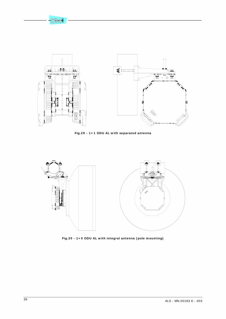
Fig.29 - 1+1 ODU AL with separated antenna
Fig.30 - 1+0 ODU AL with integral antenna (pole mounting)
ALS - MN.00183.E - 003 37
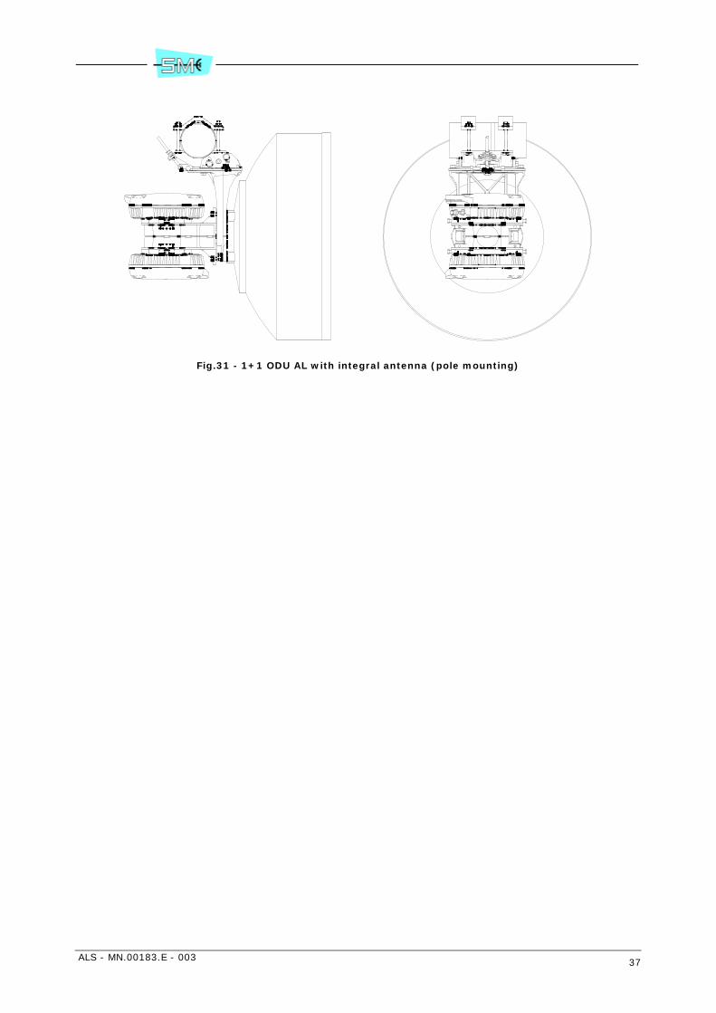
Fig.31 - 1+1 ODU AL with integral antenna (pole mounting)

38 ALS - MN.00183.E - 003
Fig.32 - 1+1 ODU AL with separated antenna (wall mounting)

ALS - MN.00183.E - 003 39
Fig.33 - ODU AS 1+1 with separated antenna

40 ALS - MN.00183.E - 003
7 CHARACTERISTICS OF THE INDOOR UNIT
7.1 GENERAL
The following IDU characteristics are guaranteed for the temperature range from –5° C to +45° C.
7.2 TRIBUTARY INTERFACE
7.2.1 2 Mbit/s interface
Input side
- Bit rate 2048 kbit/s ±50 ppm
- Line code HDB3
- Rated impedance 75 Ohm or 120 Ohm
- Rated level 2.37 Vp/75 Ohm or 3 Vp/120 Ohm
- Return loss 12 dB from 57 kHz to 102 kHz18 dB from 102 kHz to 2048 kHz14 dB from 2048 kHz to 3072 kHz
- Max attenuation of the input cable 6 dB according to trend
- Accepted jitter see mask in Table 2, CCITT Rec. G.823
- Transfer function see mask in Figure 1, CCITT Rec. G.742
- Connector type 1.0/2.3, SUB–D 25 pins, SCSI 50 pin
Output side
- Bit rate 2048 kbit/s ±50 ppm
- Rated impedance 75 Ohm or 120 Ohm
- Rated level 2.37 Vp/75 Ohm or 3 Vp/120 Ohm
- Output jitter in accordance with G.742/G.823
- Pulse shape see mask in Figure 15, CCITT Rec. G.703
- Connector type 1.0/2.3, SUB–D 25 pins, SCSI 50 pin
f
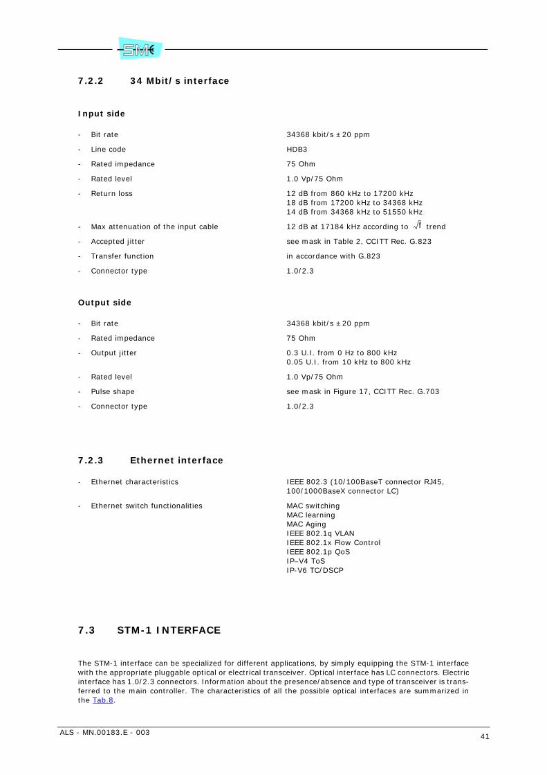
ALS - MN.00183.E - 003 41
7.2.2 34 Mbit/s interface
Input side
- Bit rate 34368 kbit/s ±20 ppm
- Line code HDB3
- Rated impedance 75 Ohm
- Rated level 1.0 Vp/75 Ohm
- Return loss 12 dB from 860 kHz to 17200 kHz18 dB from 17200 kHz to 34368 kHz14 dB from 34368 kHz to 51550 kHz
- Max attenuation of the input cable 12 dB at 17184 kHz according to trend
- Accepted jitter see mask in Table 2, CCITT Rec. G.823
- Transfer function in accordance with G.823
- Connector type 1.0/2.3
Output side
- Bit rate 34368 kbit/s ±20 ppm
- Rated impedance 75 Ohm
- Output jitter 0.3 U.I. from 0 Hz to 800 kHz0.05 U.I. from 10 kHz to 800 kHz
- Rated level 1.0 Vp/75 Ohm
- Pulse shape see mask in Figure 17, CCITT Rec. G.703
- Connector type 1.0/2.3
7.2.3 Ethernet interface
- Ethernet characteristics IEEE 802.3 (10/100BaseT connector RJ45, 100/1000BaseX connector LC)
- Ethernet switch functionalities MAC switchingMAC learningMAC AgingIEEE 802.1q VLANIEEE 802.1x Flow ControlIEEE 802.1p QoSIP–V4 ToSIP-V6 TC/DSCP
7.3 STM-1 INTERFACE
The STM-1 interface can be specialized for different applications, by simply equipping the STM-1 interfacewith the appropriate pluggable optical or electrical transceiver. Optical interface has LC connectors. Electricinterface has 1.0/2.3 connectors. Information about the presence/absence and type of transceiver is trans-ferred to the main controller. The characteristics of all the possible optical interfaces are summarized inthe Tab.8.
f
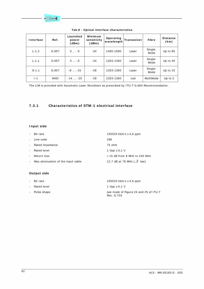
42 ALS - MN.00183.E - 003
Tab.8 - Optical interface characteristics
The LIM is provided with Automatic Laser Shutdown as prescribed by ITU-T G.664 Recommendation.
7.3.1 Characteristics of STM-1 electrical interface
Input side
- Bit rate 155520 kbit/s ±4,6 ppm
- Line code CMI
- Rated impedance 75 ohm
- Rated level 1 Vpp ±0,1 V
- Return loss ≥ 15 dB from 8 MHz to 240 MHz
- Max attenuation of the input cable 12,7 dB at 78 MHz ( law)
Output side
- Bit rate 155520 kbit/s ±4,6 ppm
- Rated level 1 Vpp ±0,1 V
- Pulse shape see mask of Figure 24 and 25 of ITU-TRec. G.703
Interface Ref.Launched
power(dBm)
Minimum sensitivity
(dBm)
Operating wavelength
Transceiver FibreDistance
(km)
L-1.2 G.957 0 ... -5 -34 1480-1580 LaserSingle-Mode
Up to 80
L-1.1 G.957 0 ... -5 -34 1263-1360 LaserSingle-Mode
Up to 40
S-1.1 G.957 -8 ... -15 -28 1263-1360 LaserSingle-Mode
Up to 15
I-1 ANSI -14 ... -20 -28 1263-1360 Led MultiMode Up to 2
f
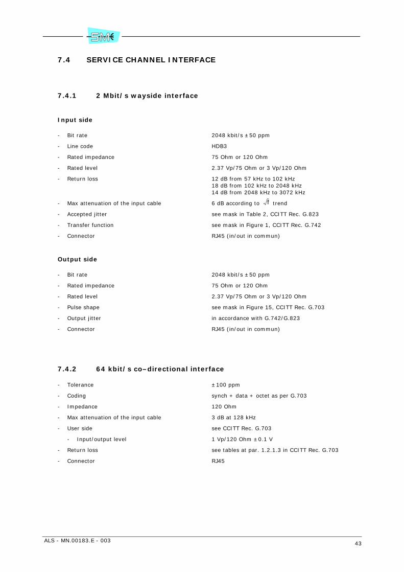
ALS - MN.00183.E - 003 43
7.4 SERVICE CHANNEL INTERFACE
7.4.1 2 Mbit/s wayside interface
Input side
- Bit rate 2048 kbit/s ±50 ppm
- Line code HDB3
- Rated impedance 75 Ohm or 120 Ohm
- Rated level 2.37 Vp/75 Ohm or 3 Vp/120 Ohm
- Return loss 12 dB from 57 kHz to 102 kHz18 dB from 102 kHz to 2048 kHz14 dB from 2048 kHz to 3072 kHz
- Max attenuation of the input cable 6 dB according to trend
- Accepted jitter see mask in Table 2, CCITT Rec. G.823
- Transfer function see mask in Figure 1, CCITT Rec. G.742
- Connector RJ45 (in/out in commun)
Output side
- Bit rate 2048 kbit/s ±50 ppm
- Rated impedance 75 Ohm or 120 Ohm
- Rated level 2.37 Vp/75 Ohm or 3 Vp/120 Ohm
- Pulse shape see mask in Figure 15, CCITT Rec. G.703
- Output jitter in accordance with G.742/G.823
- Connector RJ45 (in/out in commun)
7.4.2 64 kbit/s co–directional interface
- Tolerance ±100 ppm
- Coding synch + data + octet as per G.703
- Impedance 120 Ohm
- Max attenuation of the input cable 3 dB at 128 kHz
- User side see CCITT Rec. G.703
- Input/output level 1 Vp/120 Ohm ±0.1 V
- Return loss see tables at par. 1.2.1.3 in CCITT Rec. G.703
- Connector RJ45
f
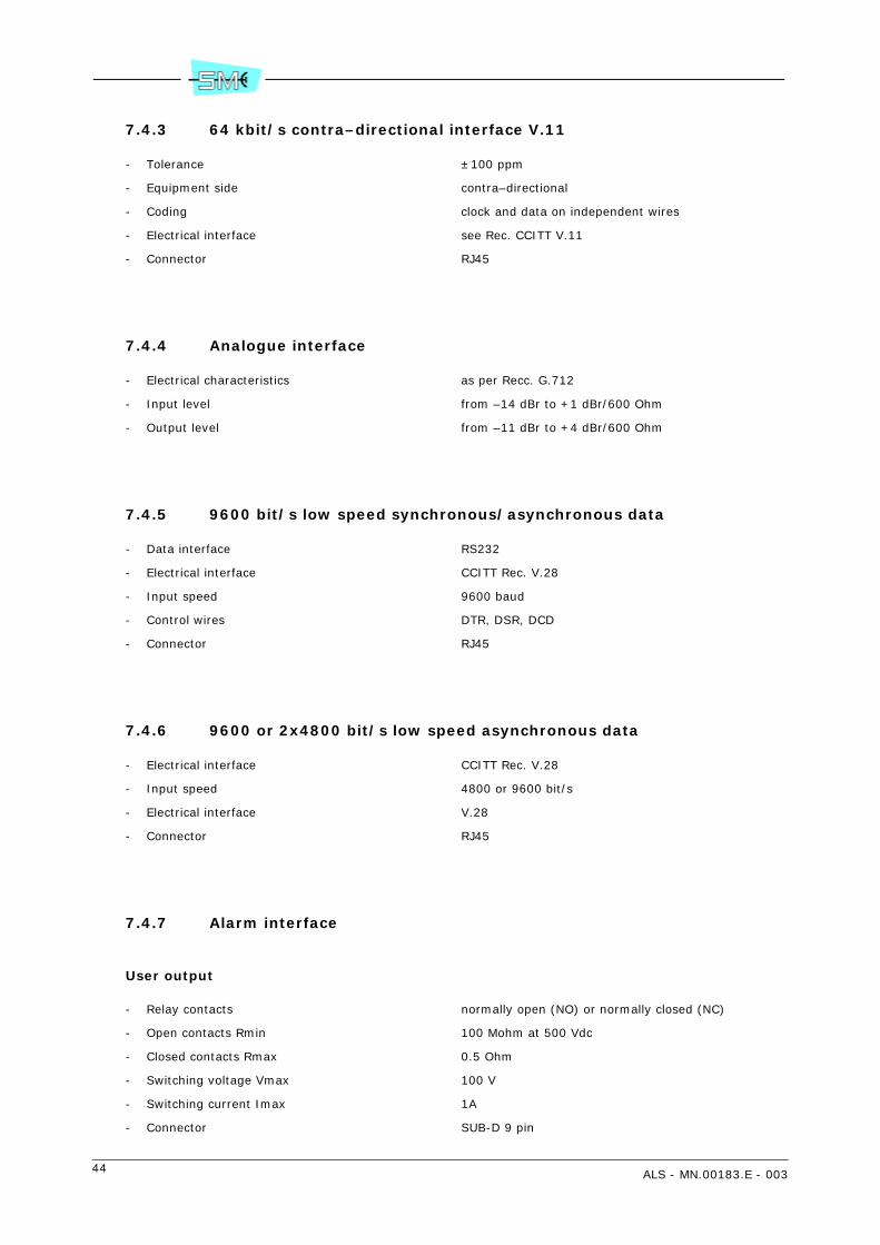
44 ALS - MN.00183.E - 003
7.4.3 64 kbit/s contra–directional interface V.11
- Tolerance ±100 ppm
- Equipment side contra–directional
- Coding clock and data on independent wires
- Electrical interface see Rec. CCITT V.11
- Connector RJ45
7.4.4 Analogue interface
- Electrical characteristics as per Recc. G.712
- Input level from –14 dBr to +1 dBr/600 Ohm
- Output level from –11 dBr to +4 dBr/600 Ohm
7.4.5 9600 bit/s low speed synchronous/asynchronous data
- Data interface RS232
- Electrical interface CCITT Rec. V.28
- Input speed 9600 baud
- Control wires DTR, DSR, DCD
- Connector RJ45
7.4.6 9600 or 2x4800 bit/s low speed asynchronous data
- Electrical interface CCITT Rec. V.28
- Input speed 4800 or 9600 bit/s
- Electrical interface V.28
- Connector RJ45
7.4.7 Alarm interface
User output
- Relay contacts normally open (NO) or normally closed (NC)
- Open contacts Rmin 100 Mohm at 500 Vdc
- Closed contacts Rmax 0.5 Ohm
- Switching voltage Vmax 100 V
- Switching current Imax 1A
- Connector SUB-D 9 pin

ALS - MN.00183.E - 003 45
User input
- Equivalent circuit recognized as a closed contact 200 Ohm resist. (max) referred to ground
- Equivalent circuit recognized as an open contact 60 kOhm (min) referred to ground
- Connector SUB-D 9 pin
7.4.8 Network Management Interface
RJ45 interface
- LAN type Ethernet Twisted Pair 802.3 10BaseT
- Connector RJ45
- Connection to LAN direct with a CAT5 Twisted Pair
- Protocol TCP/IP or IPoverOSI
BNC interface
- LAN type Ethernet thinnet 802.3 10Base2
- Connector BNC
- Connection to LAN RG58 coax. cable 50 Ohm
- Protocol TCP/IP or IPoverOSI
RS232 interface
- Electrical interface V.28
- Asynchronous baud rate 9600, 19200, 38400, 57600
- Protocol PPP
LCT RS232 interface
- Electrical interface V.28
- Asynchronous baud rate 9600, 19200, 38400, 57600
- Protocol PPP
LCT USB interface
- Electrical interface USB 1.1 version
- Baud rate 1.5 Mbit/s
- Protocol PPP
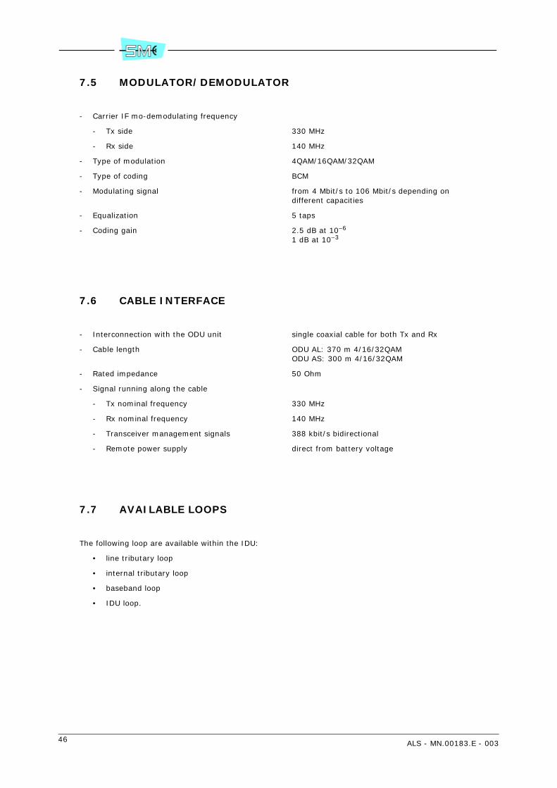
46 ALS - MN.00183.E - 003
7.5 MODULATOR/DEMODULATOR
- Carrier IF mo-demodulating frequency
- Tx side 330 MHz
- Rx side 140 MHz
- Type of modulation 4QAM/16QAM/32QAM
- Type of coding BCM
- Modulating signal from 4 Mbit/s to 106 Mbit/s depending on different capacities
- Equalization 5 taps
- Coding gain 2.5 dB at 10–6
1 dB at 10–3
7.6 CABLE INTERFACE
- Interconnection with the ODU unit single coaxial cable for both Tx and Rx
- Cable length ODU AL: 370 m 4/16/32QAMODU AS: 300 m 4/16/32QAM
- Rated impedance 50 Ohm
- Signal running along the cable
- Tx nominal frequency 330 MHz
- Rx nominal frequency 140 MHz
- Transceiver management signals 388 kbit/s bidirectional
- Remote power supply direct from battery voltage
7.7 AVAILABLE LOOPS
The following loop are available within the IDU:
• line tributary loop
• internal tributary loop
• baseband loop
• IDU loop.

ALS - MN.00183.E - 003 47
8 DESCRIPTION OF THE MODULAR IDU FOR 2 OR 34 MBIT/S TRIBUTARIES
8.1 1+0/1+1 MODULAR IDU VERSION
Description that follows is referring to LIM/CONTROLLER/RIM module the Modular IDU consists of.
8.1.1 LIM
The LIM performs the following operations:
• multiplexing process of the input tributaries
• aggregation of the multiplexed signals along with services through a Bit Insertion circuit
• processing in digital form of the baseband part of the QAM modulator (the IF part of the QAM mod-ulator takes place within the RIM
• duplication of the digital processed signal to supply two RIMs in 1+1 versions. In the full duplicatedversion the changeover occurs at tributary level.
Different baseband structures and digital processing of the signal to be forwarded to the QAM modulator/demodulator is produced by a “chip set”. Controls to the chip set and status/alarm reporting from the chipset are given/received by main controller within the CONTROLLER module.
8.1.2 Circuit description
Tx side
Refer to Fig.34.
The 2/34 Mbit/s input signal is code converted from HDB3 to NRZ format before being multiplexed. Themultiplexing scheme depends on the number and the bit rate of the input tributaries.
Attached figures show different multiplexing scheme as follows:
• Fig.35 – 2/34 Mbit/s single tributary multiplexing. The mux performs stuffing operation and gener-ates a proprietary frame to be sent to the Bit Insertion. Opposite operation occurs at the Rx side.
• Fig.36 – 2x2 Mbit/s multiplexing. The mux performs stuffing operation on each single tributary andgenerates a proprietary frame embedding the two tributaries to be sent to the Bit Insertion. Oppo-site operation occurs at the Rx side.
• Fig.37 – 4x2 Mbit/s multiplexing. The mux aggregates the four 2 Mbit/s tributaries generating a8448 kbit/s frame as per Recc. G.742. The multiplexed signal is then sent to the Bit Insertion. Op-posite operation occurs at the Rx side.
• Fig.38 – 8x2 Mbit/s multiplexing. The eight 2 Mbit/s tributaries are grouped in two 4x2 Mbit/s groupseach of one generating a G742 frame structure at 8448 kbit/s to be sent to the next Bit Insertion.Opposite operation occurs at the Rx side.

48 ALS - MN.00183.E - 003
• Fig.39 – 16x2 Mbit/s multiplexing. The sixteen 2 Mbit/s tributaries are grouped in four 4x2 Mbit/sgroups each of one generating a G.742 frame structure at 8448 kbit/s. A further multiplexing of theachieved four 8448 kbit/s streams will generate a frame structure at 34368 kbit/s as per Recc.G.751. This latter is to be sent to the Bit Insertion.The 2 Mbit/s wayside undergoes stuffing processbefore being sent to the Bit Insertion. Opposite operation occurs at the Rx side.
• Fig.40 – 32x2 Mbit/s multiplexing. This version consisted of two LIMs (master and slave) each ofone manipulating two 16x2 Mbit/s signals. Each of one will generate a 34368 kbit/s frame structureas per Recc. G.751.The two signals are sent to the Bit Insertion within the master LIM for aggregation and stuffing proc-ess. The 2 Mbit/s wayside undergoes stuffing process before being sent to the B.I. Opposite oper-ation occurs at the Rx side.
• Fig.41 – 2x34 Mbit/s multiplexing. The two 34368 kbit/s tributaries are directly sent to the Bit In-sertion for aggregation and stuffing process. Opposite situation occurs at the Rx side.
In addition to the tributary mux, an additional service mux is provided for aggregation of various servicesignals interfaced by Controller module.
The multiplexed tributary and service signals are then sent to the B.I. for aggregate frame generation oc-curring at the following bit rate depending on various versions implemented:
Tab.9 - Aggregate frame
The aggregate frame contains:
• the main signal from the MUX(s)
• the framed service signal from the service MUX
• the EOC signals for supervision message propagation towards the remote equipment
• the frame alignment word
• the bits dedicated to the FEC.
All the synch. signals to perform multiplexing (demultiplexing) and BI (BE) process are achieved from a x0at 38.88 MHz
The LIM also includes the processing in digital form (see Fig.34) of the modulating signal to be sent to themixers of the QAM modulator within the RIM.
The digital process includes:
• serial to parallel conversion
• differential encoding
• generation of the shaped modulating signals I and Q to be sent to each individual RIM.
Rx side
Refer to Fig.42.
From the two RIMs the LIM is receiving the I and Q analogue signals then digital converted for the followingprocessing:
Version Aggregate frame
2 Mbit/s 2430 kbit/s
2x2 Mbit/s 4860 kbit/s
4x2 Mbit/s 9720 kbit/s
8x2 Mbit/s 19440 kbit/s
16x2/34 Mbit/s 38880 kbit/s
32x2/2x34 Mbit/s 77760 kbit/s

ALS - MN.00183.E - 003 49
• clock recovery
• frequency and phase carrier locking
• baseband equalisation and filtering
• bit polarity decision
• differential decoding
• parallel to serial conversion to recover the aggregate signal at the receive side.
The aggregate signal is then sent to a frame alignment circuit and CRC analysis and then to the error cor-rector. The errors uncorrected by the FEC are properly counted to achieve:
• BER estimate measurement
• radio performances
HBER/LBER/Early Warning Alarm roots for monitoring purpose and Rx switching operation are taken di-rectly from CRC circuit before FEC correction.
The Rx switching receives the two aggregate signals and performs signal selection under the control of alogic circuit according with Tab.10.
The changeover is error free and the system has built in capabilities of minimising the passed errors duringthe detection time, such as the early warning criteria. The hitless switching facility provides automatic syn-chronisation of the two incoming streams up to a dynamic difference of ± 7 bits; additionally, the switchingunit is also capable of compensating static delays between the two incoming streams of up to ±7 bits. Atthe output of the Rx switch the Bit Extraction separates the main signal from the services and then, aftera proper demultiplexing process as previously described, sends them to the output interface lines.
Tab.10 - Switching priority
Priority Levels Description
Highest|||||||||||||||||||||||||↓
Lowest
Priority 1 RIM PSU Alarm
Priority 2 Manual forcing (from main controller)
Priority 3 Cable Short Alarm
Priority 3 Cable Open Alarm
Priority 3 IF Unit Alarm
Priority 3 Demodulator Failure
Priority 3 Base Band Unit Failure Alarm
Priority 3 ODU Unit Failure
Priority 3 ODU PSU Alarm
Priority 3 VCO Failure Alarm
Priority 3 High BER >10–3 (or 10–4 or 10–5, selectable by software)
Priority 4 Low BER > 10–6 (or 10–7 or 10–8, selectable by software)
Priority 5Early Warning BER > 10–9 (or 10–10 or 10–11 or 10–12, select-
able by software)
Priority 6RF Input Low (Rx threshold SW selectable from –40 to –99
dBm)
Priority 7 CRC Pulse
Priority 8 Revertive Rx (branch one preferential)
50 ALS - MN.00183.E - 003
8.1.3 RIM
Refer to Fig.43.
The RIM consists of the following main circuits:
• IF part of the QAM modulator
• IF part of the QAM demodulator
• power supply
• telemetry IDU/ODU
8.1.3.1 QAM modulator
I and Q signals from LIM are connected to a 4 or 16QAM programmable modulator. It consists of the fol-lowing circuits:
• recovery low pass filter to eliminate signal periodicity
• two mixers for carrier amplitude and phase modulation process
• 330 MHz local oscillator
• a 90° phase shifter to supply two mixers with two in quadrature carriers
• a combiner circuit to generate the QAM modulation
The thus obtained 330 MHz QAM modulated carrier is then sent to the cable interface for connection withODU.
8.1.3.2 QAM demodulator
At the receive side, from the cable interface, the 140 MHz QAM modulated carrier is sent to the QAM de-modulator passing through a cable equalizer circuit. The QAM demodulator within the RIM extracts the Iand Q signals to be sent to the digital part of the demodulator within the LIM.
8.1.3.3 Power supply
The –48 V battery voltage feeds the IDU and ODU circuitry. The service voltages for the IDU feeding areachieved through a DC/DC converter for +3.6 V generation and a step down circuit for –5V.
Both voltages are protected against overvoltages and overcurrents.
The power to the ODU is given by the same battery running through the interconnection cable.
An electronic breaker protects the battery against cable failure.
8.1.3.4 Telemetry IDU/ODU
The dialogue IDU/ODU is made–up by the main controller and associated peripherals within the ODU. Con-trols for ODU management and alarm reporting is performed making use of a bidirectional 388 kbit/sframed signals. The transport along the interconnecting cable is carried out via two FSK modulated carri-ers: 17.5 MHz from IDU to ODU; 5.5 MHz from ODU to IDU.

ALS - MN.00183.E - 003 51
8.1.4 CONTROLLER
The controller module performs the following:
• interfaces the service signals
• houses the equipment software for equipment management
• interfaces the SCT/LCT program through supervision ports
• receive external alarms and route them to relay contacts along with the internal alarms generatedby the equipment.
Warning: lithium battery inside, refer to national rules for disposal.
8.1.4.1 Service signals
The controller offers an electrical interface to the following three service channel options:
• 9600 baud/V28 with digital party line or in alternative 2x4800 baud/V28 – 9600 baud V28/RS232synchronous/asynchronous channels
• 64 kbit/s/V11 codirectional or contradirectional
• 2 Mbit/s wayside G.703.
The service channels thus interfaced are then sent to the LIM for MUX/DEMUX processing.
8.1.4.2 Equipment software
Equipment software permits to control and manage all the equipment functionality. It is distributed on twohardware levels: main controller and ODU peripheral controllers.
The dialogue between main and peripheral controllers is shown in Fig.44.
Main controller
The activities executed by the main controller are the following:
• Communication management: it makes use of SNMP as management protocol and IP or IP over OSIas communication protocol stacks. See Fig.45 for details. The interface ports for the equipmentmanagement are the following:
- LAN Ethernet 10BaseT/10Base2 or AUI
- USB port for 1+0 version
- RS232 asynchronous used for SCT/LCT connection
- RS232 asynchronous used for connection to further NEs
- EOC embedded within the PDH radio frame for connection to the remote NEs
- EOC embedded within the 2 Mbit/s tributary G.704 frame.
• Log–in: the main controller manages the equipment or network login/logout by setting and thencontrolling the user’s ID and relevant password.
• Database (MIB): validation and storing in a non–volatile memory of the equipment configurationparameters.
• Equipment configuration: distribution of the parameters stored in the MIB towards the peripheralµPs for their actuation in addition to the controls from user not stored in the MIB (i.e. loops, manualforcing etc...).
• Alarm monitoring: acquisition, filtering and correlation of the alarms gathered from slaved µPs. Lo-cal logger and alarm sending to the connected managers: SCT/LCT – NMS5UX. Management of thealarm signalling on the LIM front panel.
52 ALS - MN.00183.E - 003
• Performances: PM management as per Recc. G.828.
• Download: the main controller is equipped with two flash memory banks containing the running pro-gram (active bank) and the stand–by program (inactive bank). This permits to download a new soft-ware release to the inactive bank without distributing the traffic.Bank switch enables the new release to be used.Download activity is based on FTP protocol which downloads application programs, FPGA configu-ration, configuration files on main controller inactive bank or directly on the peripheral controllers.
Peripheral controllers
The peripheral controllers take place within the ODU and are slaved to main controller with the task of ac-tivating controls and alarm reporting of dedicated functionality.
8.1.4.3 Supervision ports
The equipment management is made by SCT/LCT program through the supervision ports.
The following are made available:
• LCT/RS232 interface ports using PPP protocol and baud rate speed up to 57600
• LAN interface using IP or IPoverOSI protocols
• EOC (Embedded Overhead Channel) using a 64 kbit/s slot of the radio frame to broadcast the su-pervision messages towards the remote terminals. The protocol used is IP or IPoverOSI.
8.2 IDU LOOPS
To control the IDU correct operation a set of local and remote loops are made available. The commandsare forwarded by the LCT/SCT program. Loop block diagram is shown by Fig.46.
8.2.1 Tributary loop
Tributary local loop
Each input tributary is routed directly to the trib. output upon receiving the command from the LCT. TheTx line transmission is still on.
Tributary remote loop
Each tributary directed towards the Rx output line is routed back to the Tx line. The Rx line is still on.
8.2.2 Baseband unit loop
This kind of loop is only local and is activated at BI/BE level. The Tx line is still on.
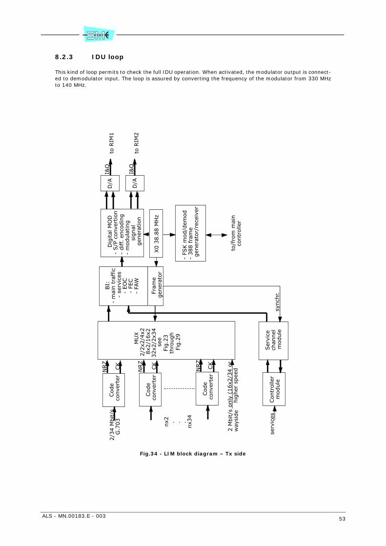
ALS - MN.00183.E - 003 53
8.2.3 IDU loop
This kind of loop permits to check the full IDU operation. When activated, the modulator output is connect-ed to demodulator input. The loop is assured by converting the frequency of the modulator from 330 MHzto 140 MHz.
Fig.34 - LIM block diagram – Tx side
Code
conve
rter
Code
conve
rter
Code
conve
rter
MU
X
2/2
x2/4
x28x2
/16x2
32x2
/2x3
4se
eFi
g.2
3
th
rough
Fig.2
9
Ser
vice
ch
annel
m
odule
Contr
olle
r m
odule
BI:
- m
ain t
raffic
- se
rvic
es-
EO
C-
FEC
- FA
W
Fram
egen
erat
or
Dig
ital
MO
D-
S/P
conve
rtio
n-
diff. e
nco
din
g-
modula
ting
signal
gen
erat
ion
X0 3
8.8
8 M
Hz
D/A
D/A
to R
IM2
to R
IM1
I&Q
I&Q
synch
r.
2/3
4 M
bit/s
G.7
03
nx2 . . .
nx3
4
2 M
bit/s
way
side
serv
ices
only
(16x2
/34 o
r hig
her
spee
dNRZ
CK
NRZ
CK
NRZ
CK
- FS
K m
od/d
emod
- 388 fra
me
gen
erat
or/
rece
iver
to/f
rom
mai
n
contr
olle
r
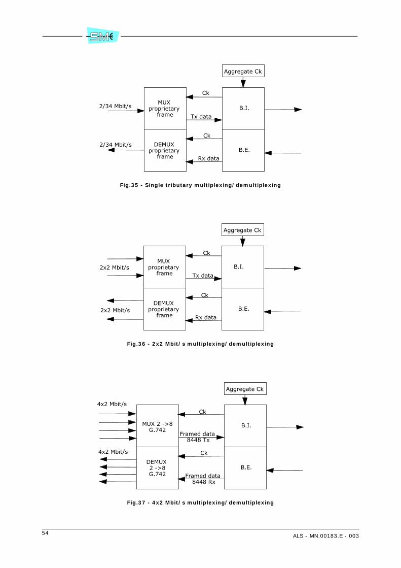
54 ALS - MN.00183.E - 003
Fig.35 - Single tributary multiplexing/demultiplexing
Fig.36 - 2x2 Mbit/s multiplexing/demultiplexing
Fig.37 - 4x2 Mbit/s multiplexing/demultiplexing
MUX proprietary
frameB.I.
DEMUX proprietary
frameB.E.
Ck
Ck
Tx data
Rx data
2/34 Mbit/s
2/34 Mbit/s
Aggregate Ck
MUX proprietary
frameB.I.
DEMUX proprietary
frameB.E.
Ck
Ck
Tx data
Rx data
2x2 Mbit/s
2x2 Mbit/s
Aggregate Ck
MUX 2 ->8G.742
B.I.
DEMUX 2 ->8G.742
B.E.
Ck
Ck
Framed data 8448 Tx
Framed data 8448 Rx
4x2 Mbit/s
4x2 Mbit/s
Aggregate Ck

ALS - MN.00183.E - 003 55
Fig.38 - 8x2 Mbit/s multiplexing/demultiplexing
MUX 2 ->8G.742
B.I.
DEMUX 8 -> 2G.742
B.E.
Ck 8448 kHz Tx
4x2 Mbit/s
4x2 Mbit/s
Aggregate Ck
MUX 2 ->8G.742
Framed data 8448 Tx
4x2 Mbit/s
DEMUX 8 -> 2G.742
4x2 Mbit/s
Framed data 8448 Rx
Ck
Data
Data
Data
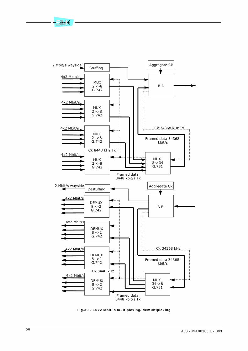
56 ALS - MN.00183.E - 003
Fig.39 - 16x2 Mbit/s multiplexing/demultiplexing
MUX2 ->8G.742
B.I.
4x2 Mbit/s
Aggregate Ck
MUX2 ->8G.742
4x2 Mbit/s
MUX2 ->8G.742
4x2 Mbit/s
MUX2 ->8G.742
4x2 Mbit/sMUX 8->34G.751
Ck 8448 kHz Tx
Framed data 8448 kbit/s Tx
Framed data 34368 kbit/s
Ck 34368 kHz Tx
DEMUX8 ->2G.742
B.E.
4x2 Mbit/s
Aggregate Ck
DEMUX8 ->2G.742
4x2 Mbit/s
DEMUX8 ->2G.742
4x2 Mbit/s
DEMUX8 ->2G.742
4x2 Mbit/sMUX 34->8G.751
Ck 8448 kHz
Framed data 8448 kbit/s Tx
Framed data 34368 kbit/s
Ck 34368 kHz
Destuffing2 Mbit/s wayside
Stuffing2 Mbit/s wayside
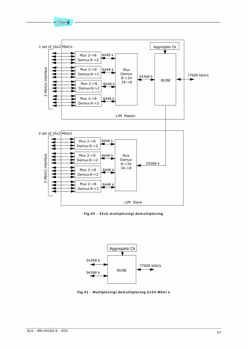
ALS - MN.00183.E - 003 57
Fig.40 - 32x2 multiplexing/demultiplexing
Fig.41 - Multiplexing/demultiplexing 2x34 Mbit/s
Mux 2->8Demux 8->2
MuxDemux8->3434->8 BI/BE
8448 k
8448 k
8448 k
8448 k
34368 k 77600 kbit/s
LIM Master
Aggregate Ck
MuxDemux8->3434->8
8448 k
8448 k
8448 k
8448 k
34368 k
LIM Slave
2 M
bit/s
inte
rfac
e2 M
bit/s
inte
rfac
e1 set of 16x2 Mbit/s
2 set of 16x2 Mbit/s
Mux 2->8Demux 8->2
Mux 2->8Demux 8->2
Mux 2->8Demux 8->2
Mux 2->8Demux 8->2
Mux 2->8Demux 8->2
Mux 2->8Demux 8->2
Mux 2->8Demux 8->2
BI/BE77600 kbit/s
34368 k
34368 k
Aggregate Ck
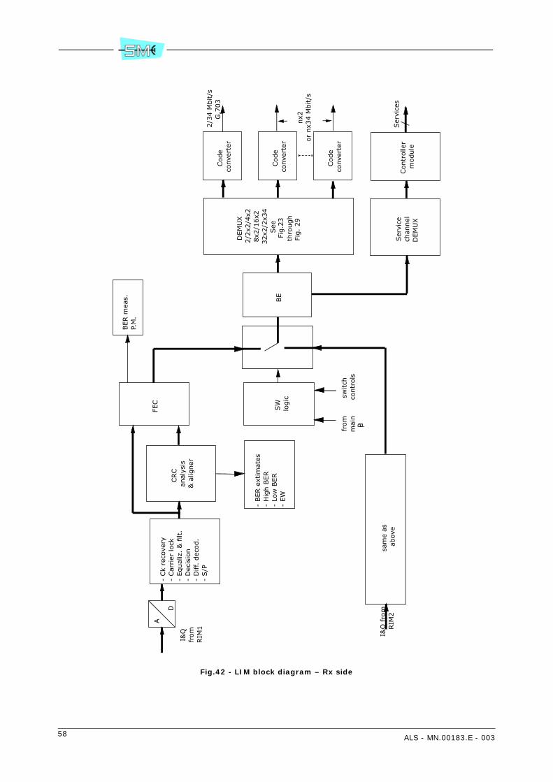
58 ALS - MN.00183.E - 003
Fig.42 - LIM block diagram – Rx side
A
D-
Ck
reco
very
- Car
rier
lock
- Equal
iz.
& filt
.-
Dec
isio
n
- D
iff. d
ecod.
- S/P
CRC
anal
ysis
& a
ligner
FEC
- BER e
xtim
ates
- H
igh B
ER
- Lo
w B
ER
- EW
SW
lo
gic
from
m
ain
µP
switch
co
ntr
ols
sam
e as
ab
ove
I&Q
fr
om
RIM
1
I&Q
fro
m
RIM
2
BE
DEM
UX
2/2
x2/4
x28x2
/16x2
32x2
/2x3
4See
Fig.2
3
th
rough
Fig.
29
Ser
vice
chan
nel
DEM
UX
Code
conve
rter
Code
conve
rter
Code
conve
rter
Contr
olle
r m
odule
2/3
4 M
bit/s
G.7
03
nx2
or
nx3
4 M
bit/s
Ser
vice
s
BER m
eas.
P.M
.
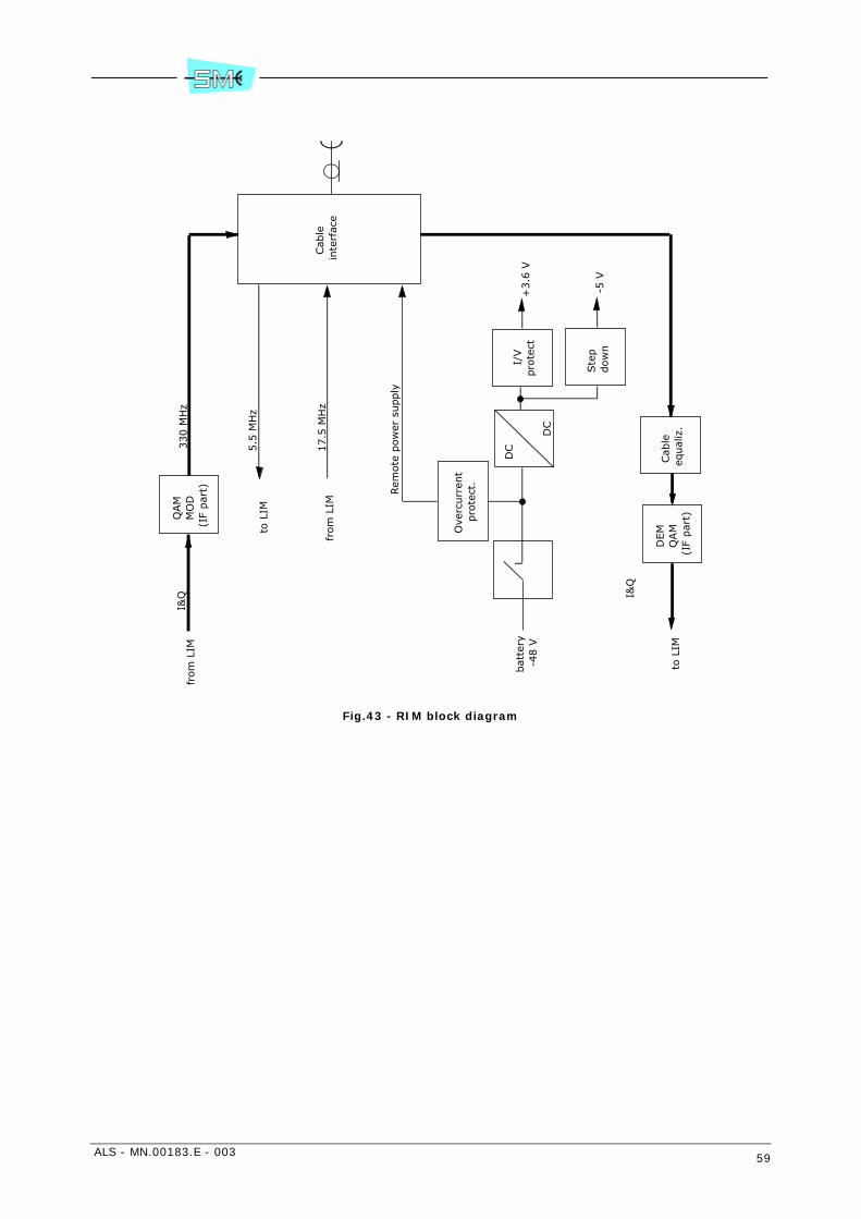
ALS - MN.00183.E - 003 59
Fig.43 - RIM block diagram
Cab
le
inte
rfac
e
Ove
rcurr
ent
pro
tect
.
Rem
ote
pow
er s
upply
5.5
MH
z
QAM
MO
D(I
F par
t)
330 M
Hz
DC
DC
from
LIM
I&Q
bat
tery
-4
8 V
I/V
pro
tect
Ste
p
dow
n
+3.6
V
-5 V
Cab
le
equal
iz.
DEM
QAM
(IF
par
t)
I&Q
to L
IM
17.5
MH
zfr
om
LIM
to L
IM
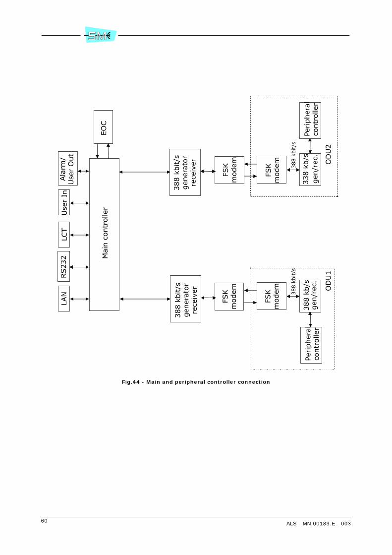
60 ALS - MN.00183.E - 003
Fig.44 - Main and peripheral controller connection
Mai
n c
ontr
olle
r
338 k
b/s
388 k
bit/s
LAN
RS232
LCT
Use
r In
Ala
rm/
Use
r O
ut
FSK
modem
FSK
modem O
DU
2
388 k
b/s
388 k
bit/s
FSK
modem
FSK
modem O
DU
1
EO
C
388 k
bit/s
gen
erat
or
rece
iver
388 k
bit/s
gen
erat
or
rece
iver
gen
/rec
.Pe
ripher
alco
ntr
olle
rPe
ripher
alco
ntr
olle
rgen
/rec
.
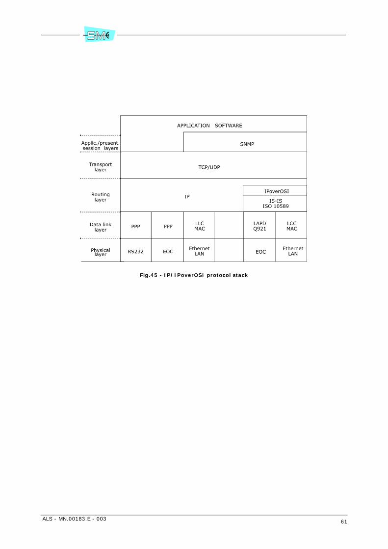
ALS - MN.00183.E - 003 61
Fig.45 - IP/IPoverOSI protocol stack
APPLICATION SOFTWARE
SNMP
TCP/UDP
IPIPoverOSI
IS-ISISO 10589
PPP PPPLLCMAC
LAPDQ921
LCCMAC
RS232 EOCEthernet
LAN EOCEthernet
LAN
Applic./present.session layers
Transportlayer
Routinglayer
Data linklayer
Physicallayer
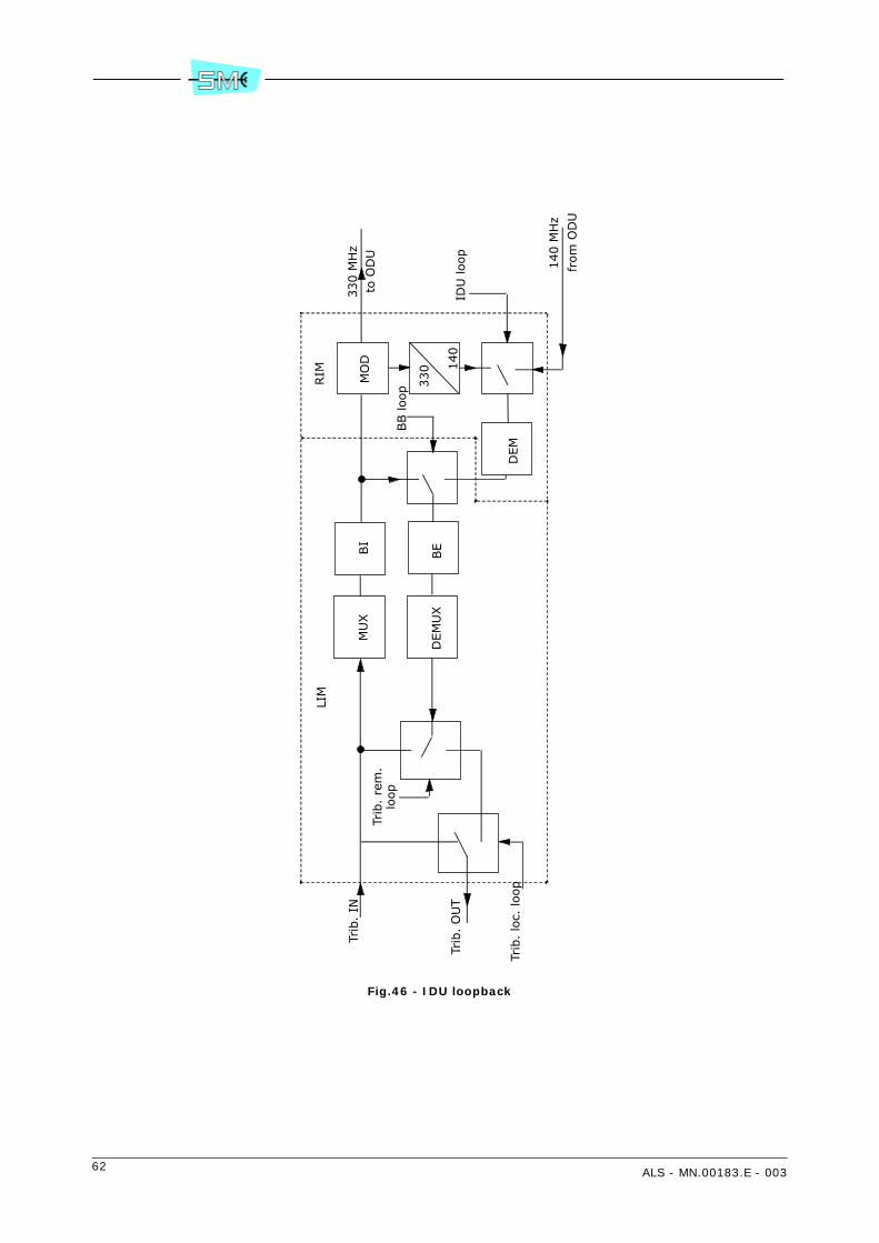
62 ALS - MN.00183.E - 003
Fig.46 - IDU loopback
330 M
Hz
to O
DU
MU
X
BB loop
Trib
. lo
c. loop
Trib
. IN
DEM
UX
BI
BE
MO
D
330 1
40
IDU
loop
140 M
Hz
from
OD
U
Trib
. O
UT
Trib
. re
m.
loop
DEM
LIM
RIM

ALS - MN.00183.E - 003 63
9 DESCRIPTION OF THE MODULAR IDU WITH LIM ETHERNET (2 MBIT/S TRIBUTARIES + ETHERNET TRAFFIC)
Description that follows covers indoor unit with Ethernet ports, 1+0/1+1 Modular version. Paragraph 9.1.1LIM Ethernet: 2 Mbit/s tributaries deals with 2 Mbit/s signals and paragraph 9.1.3 LIM Ethernet: Ethernettraffic deals with Ethernet traffic treatment.
LIM Ethernet contains all the circuits of LIM with 2 Mbit/s interfaces plus some specific circuits for Ethernetinterface.
9.1 1+0/1+1 MODULAR IDU
Description that follows is referring to LIM/CONTROLLER/RIM modules contained into IDU.
9.1.1 LIM Ethernet: 2 Mbit/s tributaries
The LIM Ethernet performs the following operations:
• multiplexing process of the input tributaries
• aggregation of the multiplexed signals along with services through a Bit Insertion circuit
• processing in digital form of the baseband part of the QAM modulator (the IF part of the QAM mod-ulator takes place within the RIM
• duplication of the digital processed signal to supply two RIMs in 1+1 versions. In the full duplicatedversion the changeover occurs at tributary level
• concatenation of 2 Mbit/s streams
• connection between a local LAN port and a remote LAN port.
Different baseband structures and digital processing of the signal to be forwarded to the QAM modulator/demodulator is produced by a “chip set”. Controls to the chip set and status/alarm reporting from the chipset are given/received by main controller within the CONTROLLER module.
9.1.2 Circuit description
Tx side
The 2/34 Mbit/s input signal is code converted from HDB3 to NRZ format before being multiplexed. Themultiplexing scheme depends on the number and the bit rate of the input tributaries.
In the following are described different multiplations:

64 ALS - MN.00183.E - 003
• 2/34 Mbit/s single tributary multiplexing. The mux performs stuffing operation and generates a pro-prietary frame to be sent to the Bit Insertion. Opposite operation occurs at the Rx side.
• 2x2 Mbit/s multiplexing. The mux performs stuffing operation on each single tributary and gener-ates a proprietary frame embedding the two tributaries to be sent to the Bit Insertion. Oppositeoperation occurs at the Rx side.
• 4x2 Mbit/s multiplexing. The mux aggregates the four 2 Mbit/s tributaries generating a 8448 kbit/s frame as per Recc. G.742. The multiplexed signal is then sent to the Bit Insertion. Opposite oper-ation occurs at the Rx side.
• 8x2 Mbit/s multiplexing. The eight 2 Mbit/s tributaries are grouped in two 4x2 Mbit/s groups eachof one generating a G742 frame structure at 8448 kbit/s to be sent to the next Bit Insertion. Oppo-site operation occurs at the Rx side.
• 16x2 Mbit/s multiplexing. The sixteen 2 Mbit/s tributaries are grouped in four 4x2 Mbit/s groupseach of one generating a G.742 frame structure at 8448 kbit/s. A further multiplexing of theachieved four 8448 kbit/s streams will generate a frame structure at 34368 kbit/s as per Recc.G.751. This latter is to be sent to the Bit Insertion.The 2 Mbit/s wayside undergoes stuffing processbefore being sent to the Bit Insertion. Opposite operation occurs at the Rx side.
• 32x2 Mbit/s multiplexing. This version consisted of two multiplexers of 16x2 Mbit/s signals. Each ofone will generate a 34368 kbit/s frame structure as per Recc. G.751.The two signals are sent to the Bit Insertion within the LIM for aggregation and stuffing process.The 2 Mbit/s wayside undergoes stuffing process before being sent to the B.I.Opposite operation occurs at the Rx side.
In addition to the tributary mux, an additional service mux is provided for aggregation of various servicesignals interfaced by Controller module.
The multiplexed tributary and service signals are then sent to the B.I. for aggregate frame generation oc-curring at the following bit rate depending on various versions implemented:
Tab.11 - Aggregate frame
The aggregate frame contains:
• the main signal from the MUX(s)
• the framed service signal from the service MUX
• the EOC signals for supervision message propagation towards the remote equipment
• the frame alignment word
• the bits dedicated to the FEC.
The LIM also includes the processing in digital form of the modulating signal to be sent to the mixers ofthe QAM modulator within the RIM.
The digital process includes:
• serial to parallel conversion
• differential encoding
• generation of the shaped modulating signals I and Q to be sent to each individual RIM.
Version Aggregate frame
2 Mbit/s 2430 kbit/s
2x2 Mbit/s 4860 kbit/s
4 Mbit/s 4860 kbit/s
8 Mbit/s 9720 kbit/s
16 Mbit/s 19440 kbit/s
32 Mbit/s 38880 kbit/s
64 Mbit/s 77760 kbit/s

ALS - MN.00183.E - 003 65
Rx side
From the two RIMs the LIM is receiving the I and Q analogue signals then digital converted for the followingprocessing:
• clock recovery
• frequency and phase carrier locking
• baseband equalisation and filtering
• bit polarity decision
• differential decoding
• parallel to serial conversion to recover the aggregate signal at the receive side.
The aggregate signal is then sent to a frame alignment circuit and CRC analysis and then to the error cor-rector. The errors uncorrected by the FEC are properly counted to achieve:
• BER estimate measurement
• radio performances
HBER/LBER/Early Warning Alarm roots for monitoring purpose and Rx switching operation are taken di-rectly from CRC circuit before FEC correction.
The Rx switching receives the two aggregate signals and performs signal selection under the control of alogic circuit according with Tab.12.
The changeover is error free and the system has built in capabilities of minimising the passed errors duringthe detection time, such as the early warning criteria. The hitless switching facility provides automatic syn-chronisation of the two incoming streams up to a dynamic difference of ± 7 bits; additionally, the switchingunit is also capable of compensating static delays between the two incoming streams of up to ±7 bits. Atthe output of the Rx switch the Bit Extraction separates the main signal from the services and then, aftera proper demultiplexing process as previously described, sends them to the output interface lines.
Tab.12 - Switching priority
Priority Levels Description
Highest|||||||||||||||||||||||||↓
Lowest
Priority 1 RIM PSU Alarm
Priority 2 Manual forcing (from main controller)
Priority 3 Cable Short Alarm
Priority 3 Cable Open Alarm
Priority 3 IF Unit Alarm
Priority 3 Demodulator Failure
Priority 3 Base Band Unit Failure Alarm
Priority 3 ODU Unit Failure
Priority 3 ODU PSU Alarm
Priority 3 VCO Failure Alarm
Priority 3 High BER >10–3 (or 10–4 or 10–5, selectable by software)
Priority 4 Low BER > 10–6 (or 10–7 or 10–8, selectable by software)
Priority 5Early Warning BER > 10–9 (or 10–10 or 10–11 or 10–12, select-
able by software)
Priority 6RF Input Low (Rx threshold SW selectable from –40 to –99
dBm)
Priority 7 CRC Pulse
Priority 8 Revertive Rx (branch one preferential)

66 ALS - MN.00183.E - 003
9.1.3 LIM Ethernet: Ethernet traffic
Two versions of LIM Ethernet are available. They only differs for interface number:
• LIM Ethernet 4x2 Mbit/s + 3x10/100BaseT
• LIM Ethernet 16x2 Mbit/s + 4x10/100BaseT
In the following Ethernet interface circuits are described.
For the description of all the other circuits relative to 2 Mbit/s interface and the structure of LIM pleaserefer to previous paragraph. LIM Ethernet is equipped with the following interfaces:
• electrical interface Ethernet 10/100 BaseT IEEE 802.3
• from 0 to 4x2 Mbit/s (E1) interface
• total capacity from 2 to 64 Mbit/s or 105 Mbit/s
Most important functions of LIM Ethernet are:
• concatenation of Ethernet traffic in 2 Mbit/s tributaries and relevant multiplation
• LAPS Link Access Procedure SDH (ITU X.86) for concatenated 2 Mbit/s
• switch between a local LAN port and the radio LAN port
• MAC switching
• MAC address learning
• MAC address aging
• Ethernet interface with autonegotiation 10/100, full duplex, half duplex
- Ethernet interface with Flow Control, Back Pressure, MDI/MDX crossover
• network segmentation into the switch
• virtual LAN as per IEEE 802.1q (anyone from 0 to 4095 VID for a maximum of 64 memory location)(see Fig.52)
• layer 2 QoS, priority management as per IEEE 802.1p (see Fig.52)
• layer 3 ToS/DSCP (see Fig.54 and Fig.55)
• packet forwarding
A block diagram of LIM Ethernet module can be found into Fig.51.
Into LIM Ethernet there is a “switch” with 3 external ports and 1internal ports. External ports are electricalEthernet 10/100BaseT interfaces placed on the front panel. Internal port is connected to radio side stream.
Ethernet traffic coming from external ports goes to internal port radio side. The radio side port is connectedto one or two streams group of concatenated 2 Mbit/s. One stream for capacity up to 16x2 Mbit/s and twostreams for capacity of 12 – 16 2 Mbit/s streams, plus other 16x2 Mbit/s streams in case of maximumcapacity.
In Tx side Ethernet traffic is packet into a protocol called LAPS similar to HDLC. The resulting stream isdivided into the used number of 2 Mbit/s streams. The 2 Mbit/s streams are then multiplexed, like intostandard LIM, together with 2 Mbit/s arriving from front panel, the resulting stream goes to the modulator,see Fig.51.
In Rx the stream arriving from the demodulator is divided into the 2 Mbit/s streams, like into standard LIM,then the 2 Mbit/s not used into the front panel 2 Mbit/s are concatenated and sent to Ethernet circuits.Resulting stream, after LAPS protocol control, is sent to switch internal port.
9.1.3.1 2 Mbit/s tributaries
LIM Ethernet module uses the 16x2 Mbit/s mode of AL radio link. Tributary channels at 2 Mbit/s (E1) areconnected to 8 coaxial connectors 1.0/2.3 into front panel. 2 Mbit/s streams are multiplexed as into stand-ard LIM.
From 0 to 16 2 Mbit/s tributaries can be selected to be used via SCT/LCT program, all the other available2 Mbit/s are sent to switch internal port.
ALS - MN.00183.E - 003 67
For 100 Mbit/s version can be selected up to 2 tributaries, position number 3 and 4 in tributary connectorsare available for wayside connection (2 Mbit/s each).
9.1.3.2 Electrical Ethernet interface
The electrical Ethernet/Fast Ethernet interfaces are type IEEE 802.3 10/100BaseT with RJ45 connector. Forinput or output signals at RJ45 please refer to chapter 19 MODULAR IDU USER CONNECTIONS. Cable canbe UTP (Unshielded Twisted Pair) or STP (Shielded Twisted Pair) Category 5.
Standard coding:
• Ethernet 10 Mbit/s: Manchester
• Fast Ethernet 100 Mbit/s: MLT–3 ternary
EMC/EMI protection:
• input and output pins are galvanically isolated through a transformer
• to reduce EMI every pin at RJ45 connector is terminated even if not used
• two signal lines are equipped with low capacity secondary protection to sustain residuals of possibleelectrostatic discharges (ESD).With LCT/SCT program it is possible to activate autonegotiation (speed/duplex/flow control) on 10/100BaseT interface.
9.1.3.3 Front panel LEDs
On FEM front panel there are a total of 6 Leds. There are 2 Leds for any Ethernet interface:
• DUPLEX: colour green, On = full duplex, OFF = half duplex
• LINK/ACT: colour green, ON = link up without activity, OFF = link down, BLINKING = link with ac-tivity on Rx and Tx.
9.1.3.4 Switch function
A radio link AL equipped with a LIM/Ethernet module can operate like a switch between two or more sep-arated LANs with the following advantages:
• to connect two separated LANs at a distance even greater than the maximum limits of 2.5 km (forEthernet)
• to connect two LANs via radio within a complex digital network
• to keep separated the traffic into two LANs towards MAC filtering to get a total traffic greater thantraffic in a single LAN.
The switch realized into LIM/Ethernet module is transparent (IEEE 802.1d and 802.q) into the same Vlandescribed by VLAN Configuration Table. It works at data link level, Layer 2 of OSI pile, and leave untouchedLayer 3 and it takes care to send traffic from a local LAN to another (Local or Remote). Routing is only onthe basic of Level 2 addresses, sublevel MAC.
The operation is the following:
• when a LAN interface receives a MAC frame, on the basis of destination address, it decides whichLAN to send it
• if destination address is on originating LAN the frame is discarded
• if destination address is a known address (towards address learning procedure) and is present intolocal address table the frame is sent only on destination LAN (MAC switching)
• otherwise the frame is sent to all ports with the same VLAN ID (flooding).

68 ALS - MN.00183.E - 003
The switch is very different from a Hub, which copies slavishly everything that receives from a line on allthe others. The switch, in fact, acquires a frame, analyses it, reconstruct it and routes it and compensatesalso the different speeds of the interfaces, therefore an input can be at 100 Mbit/s and output at 10 Mbit/s.
The mechanism is the following:
• from the moment of its activation, the switch examines all the frames that arrive it from differentLANs, and on these basis it builds its routing tables progressively.In fact, every received frame allows to know on what LAN the sending station is located (MAC ad-dress learning).
• every frame that arrives to the switch is rebroadcasted:
- if the switch has the destination address into the routing table, sends the frame only into thecorresponding LAN
- otherwise the frame is sent to all the LANs except the originating (flooding)
- as soon as the swicth increases its knowledge of different machines, the retransmission becomesmore and more selective (and therefore more efficient)
• the routing tables are updated every some minutes (programmable), removing addresses not alivein the last period (so, if a machine is moved, within a few minute it is addressed correctly) (MACaddress aging).
The whole process is restricted to the ports which are members of the same Vlan as described into VlanConfiguration Table.
9.1.3.5 Ethernet Full Duplex function
The first realizations of the Ethernet network were on coaxial cable with the 10Base5 standard.
According to this standard Ethernet interfaces (e.g. PC) are connected to the coaxial cable in parallel andare normally in receiving mode. Only one PC, at a certain time, transmits on the cable, the others are re-ceiving, so this is half duplex mode, and only one PC uses the received message.
Then the coaxial cable was progressively replaced by the pairs cable Unshielded Twisted Pair (UTP) as per10BaseT standard. Normally there are four pairs into UTP Cat5 cable but two pairs are used with 10BaseT,one for Tx one for Rx. Into 10Base5 and 10BaseT standards, network protocols are the same the differencelays into the electrical interface. UTP cable is connected point to point between a hub and a Ethernet in-terface. Network structure is a star where the server is connected to a hub and from this a UTP cable islaid down for each Ethernet interface starts.
The further step is to replace the hub with a more powerful equipment, e.g. a switch. In this case it ispossible to activate transmission on both pairs at the same time, on one twisted pair for one direction, onthe other pair for opposite direction. Thus we obtain full duplex transmission on UTP.
Activating full duplex transmission it is possible to obtain a theoretical increase of performance of nearly100%. Full duplex mode can be activated into 10/100BaseT interfaces manually or with autonegotiation100BaseFx operates always into full duplex mode.
9.1.3.6 Link Loss Forwarding
Link Loss Forwarding (LLF) is an alarm status of ethernet interface.
LLF can be enabled or disabled. If LLF is enabled an US radio alarm condition will generate the alarm statusof Ethernet interface blocking any transmission to it. LLF can be enabled for each ports at front panel. WithLLF enabled the equipment connected (routers, switches so on) can be notified that radio link is not avail-able and can temporarily reroute the traffic.
9.1.3.7 MDI/MDIX cross–over
The Ethernet electrical interface into FEM module can be defined by SCT program as MDI or MDIX to cross–over between pairs so that external cross–over cable is not required.
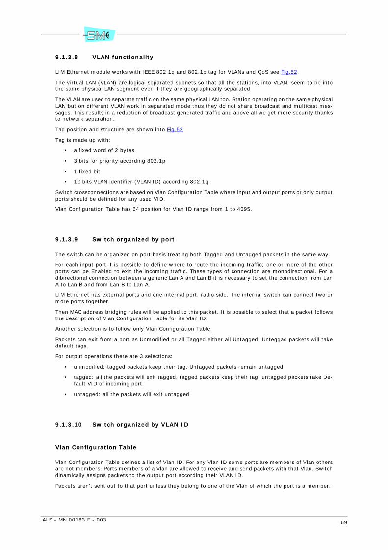
ALS - MN.00183.E - 003 69
9.1.3.8 VLAN functionality
LIM Ethernet module works with IEEE 802.1q and 802.1p tag for VLANs and QoS see Fig.52.
The virtual LAN (VLAN) are logical separated subnets so that all the stations, into VLAN, seem to be intothe same physical LAN segment even if they are geographically separated.
The VLAN are used to separate traffic on the same physical LAN too. Station operating on the same physicalLAN but on different VLAN work in separated mode thus they do not share broadcast and multicast mes-sages. This results in a reduction of broadcast generated traffic and above all we get more security thanksto network separation.
Tag position and structure are shown into Fig.52.
Tag is made up with:
• a fixed word of 2 bytes
• 3 bits for priority according 802.1p
• 1 fixed bit
• 12 bits VLAN identifier (VLAN ID) according 802.1q.
Switch crossconnections are based on Vlan Configuration Table where input and output ports or only outputports should be defined for any used VID.
Vlan Configuration Table has 64 position for Vlan ID range from 1 to 4095.
9.1.3.9 Switch organized by port
The switch can be organized on port basis treating both Tagged and Untagged packets in the same way.
For each input port it is possible to define where to route the incoming traffic; one or more of the otherports can be Enabled to exit the incoming traffic. These types of connection are monodirectional. For adibirectional connection between a generic Lan A and Lan B it is necessary to set the connection from LanA to Lan B and from Lan B to Lan A.
LIM Ethernet has external ports and one internal port, radio side. The internal switch can connect two ormore ports together.
Then MAC address bridging rules will be applied to this packet. It is possible to select that a packet followsthe description of Vlan Configuration Table for its Vlan ID.
Another selection is to follow only Vlan Configuration Table.
Packets can exit from a port as Unmodified or all Tagged either all Untagged. Unteggad packets will takedefault tags.
For output operations there are 3 selections:
• unmodified: tagged packets keep their tag. Untagged packets remain untagged
• tagged: all the packets will exit tagged, tagged packets keep their tag, untagged packets take De-fault VID of incoming port.
• untagged: all the packets will exit untagged.
9.1.3.10 Switch organized by VLAN ID
Vlan Configuration Table
Vlan Configuration Table defines a list of Vlan ID, For any Vlan ID some ports are members of Vlan othersare not members. Ports members of a Vlan are allowed to receive and send packets with that Vlan. Switchdinamically assigns packets to the output port according their VLAN ID.
Packets aren’t sent out to that port unless they belong to one of the Vlan of which the port is a member.

70 ALS - MN.00183.E - 003
The ports, from which the packet can be sent, are defined in the VLAN Table. The VLAN of incoming packetis filtered only if the parameter “Ingress Filtering Check” is set as “Secure”.
After having filtered the ports from which packet can go out according to VALN Table, the control of packetand port Vlan membership MAC address bridging rules will be applied to this packet.
Ingress Filtering Check
This is a process to check an incoming packet to compare its Valn ID to input port’s Vlan membership. WithIngress Filtering Check it is possible to permit only to tagged packets to enter the switch. If the port is notmember of the Vlan n. XX all the incoming packets with Vlan ID XX will be dropped.
There are 3 option into Ingress Filtering Check to manage incoming packets:
• Disable: all Tagged and Untagged packets can transit into the switch following setting of switch or-ganized by port.
• Fallback: Incoming packets without TAG 802.1q follow the rules of switch organized by port, Taggedframes with Vlan ID described into the Vlan Configuration Table follow the rules of the table, Taggedframes with Vlan ID not described into the Vlan Configuration Table follow the rules of switch or-ganized by port.
• Secure: Incoming packets without TAG 802.1q cannot enter the switch, Tagged frames with VlanID described into the Vlan Configuration Table follow the rules of the table, Tagged frames with VlanID not described into the Vlan Configuration Table cannot enter the switch.
Operations at the input. At the input port the packet is received and a switching decision must be made.The switch analyses the Vlan ID (if present) and decides whether and where to forward the frame. If thereceived packet is untagged, the switch sends the packet to the port specified into incoming port “Lan perport” settings. If the packet is tagged the switch check the other destination ports to find at least one withthe same Vlan ID and put the packet into output port queue. If the Vlan ID is not listed into Vlan Config-uration Table the switch sends the packet to the port specified into incoming port “Lan per port” settings.Then MAC address bridging rules will be applied to this packet.
Operations at the output. For each output port there are the following selections for outgoing packets.
• Disable output port
• Enable unchanged: tagged packets keep their tag. Untagged packets remain untagged.
• Enable tagged: all the packets will exit tagged with Vlan ID specified into Vlan Configuration Table,tagged packets keep their tag, untagged packets take Default VID of incoming port.
• Untagged: all the packets will exit untagged.
9.1.3.11 Layer 2, Priority function, QoS, 802.1p
Some services as voice overIP and videoconference have some time limits to work properly. A solution isto increase the priority of time sensitive packets. In this case random crowding coming from other servicesaffects the delay of prioritized packets a lot less.Into LIM Ethernet module different priority of incoming packets is managed using Tag defined into IEEE802.1p (see Fig.52).Every switch output port holds 4 output queues: queue 4 has highest priority, queue 0 has the lowest pri-ority (see Fig.53).
Priority can be organized by incoming port or by incoming priority tag:
• Priority by incoming port. For Untagged packets at each input ports it is decided to send the packetsto one of the 4 queues of output ports defining which is the Default Priority Queue: Queue = 0, 1,2, 3. For Tagged packets it is necessary to Disable Priority so they will go in the same queue ofUntagged packets.
• Priority by incoming priority. For tagged packets for each priority tag (3 bits = for 7 priority levels)it is possible to define where to send the packets, into Queue from 0 to 3. Priority must be enableon 802.1p mode only or IpToS mode only (see next paragraph) or first check 802.1p mode andIpToS mode either first check IpToS mode only (see next paragraph) or first check 802.1p modeand IpToS mode either first check IpToS mode and then 808.1q. For untagged packets the priorityis defined only by incoming port..

ALS - MN.00183.E - 003 71
• Outgoing packet policy at output ports can be WFQ (Wait Fair Queue) with fixed proportional outputpolicy (8 packets from Queue 3, 4 from Queue 2, 4 from Queue 1, 1 from Queue 0) or “Strict Pri-ority” that means that a queue completely empties before processing the next one.
9.1.3.12 Layer 3, Priority function, QoS, IP–V4 ToS (DSCP)
Only for IP packets it is possible to use incoming Layer 3 ToS (see Fig.54) to prioritize incoming packets.The 8 bits available can be read as 7 bits of ToS or 6 bits of DSCP as shown in Fig.55.
According priority defined into ToS/DSCP the packet is sent into high priority queue low priority queue ofoutput ports.
With SCT/LCT program it is possible to select a different output queue for any ToS/DSCP priority level ateach input port.
9.1.4 RIM
Refer to Fig.47.
The RIM consists of the following main circuits:
• IF part of the QAM modulator
• IF part of the QAM demodulator
• power supply
• telemetry IDU/ODU.
9.1.4.1 QAM modulator
I and Q signals from LIM are connected to a 4 or 16QAM programmable modulator. It consists of the fol-lowing circuits:
• recovery low pass filter to eliminate signal periodicity
• two mixers for carrier amplitude and phase modulation process
• 330 MHz local oscillator
• a 90° phase shifter to supply two mixers with two in quadrature carriers
• a combiner circuit to generate the QAM modulation
The thus obtained 330 MHz QAM modulated carrier is then sent to the cable interface for connection withODU.
9.1.4.2 QAM demodulator
At the receive side, from the cable interface, the 140 MHz QAM modulated carrier is sent to the QAM de-modulator passing through a cable equalizer circuit. The QAM demodulator within the RIM extracts the Iand Q signals to be sent to the digital part of the demodulator within the LIM.
9.1.4.3 Power supply
The –48 V battery voltage feeds the IDU and ODU circuitry. The service voltages for the IDU feeding areachieved through a DC/DC converter for +3.6 V generation and a step down circuit for –5V.
72 ALS - MN.00183.E - 003
Both voltages are protected against overvoltages and overcurrents.
The power to the ODU is given by the same battery running through the interconnection cable. An elec-tronic breaker protects the battery against cable failure.
9.1.4.4 Telemetry IDU/ODU
The dialogue IDU/ODU is made–up by the main controller and associated peripherals within the ODU. Con-trols for ODU management and alarm reporting is performed making use of a bidirectional 388 kbit/sframed signals. The transport along the interconnecting cable is carried out via two FSK modulated carri-ers: 17.5 MHz from IDU to ODU; 5.5 MHz from ODU to IDU.
9.1.5 CONTROLLER
The controller module performs the following:
• interfaces the service signals
• houses the equipment software for equipment management
• interfaces the SCT/LCT program through supervision ports
• receive external alarms and route them to relay contacts along with the internal alarms generatedby the equipment.
9.1.5.1 Service signals
The controller offers an electrical interface to the following three service channel options:
• 9600 baud/V28 with digital party line or in alternative 2x4800 baud/V28 – 9600 baud V28/RS232synchronous/asynchronous channels
• 64 kbit/s/V11 codirectional or contradirectional
• 2 Mbit/s wayside G.703.
The service channels thus interfaced are then sent to the LIM for MUX/DEMUX processing.
For 100 Mbit/s version the following service channels are available:
• 9600 baud/V28 with digital party line or in alternative 2x4800 baud/V28 – 9600 baud V28/RS232synchronous/asynchronous channels
• 2x2 Mbit/s wayside G.703 channels.
9.1.6 Equipment software
Equipment software permits to control and manage all the equipment functionality. It is distributed on twohardware levels: main controller and ODU peripheral controllers.
The dialogue between main and peripheral controllers is shown in Fig.48.

ALS - MN.00183.E - 003 73
Main controller
The activities executed by the main controller are the following:
• Communication management: it makes use of SNMP as management protocol and IP or IP over OSIas communication protocol stacks. See Fig.49 for details. The interface ports for the equipmentmanagement are the following:
- LAN Ethernet 10BaseT/10Base2 or AUI
- USB port for 1+0 version
- RS232 asynchronous used for SCT/LCT connection
- RS232 asynchronous used for connection to further NEs
- EOC embedded within the PDH radio frame for connection to the remote NEs
- EOC embedded within the 2 Mbit/s tributary G.704 frame.
• Log–in: the main controller manages the equipment or network login/logout by setting and thencontrolling the user’s ID and relevant password.
• Database (MIB): validation and storing in a non–volatile memory of the equipment configurationparameters.
• Equipment configuration: distribution of the parameters stored in the MIB towards the peripheralµPs for their actuation in addition to the controls from user not stored in the MIB (i.e. loops, manualforcing etc...).
• Alarm monitoring: acquisition, filtering and correlation of the alarms gathered from slaved µPs. Lo-cal logger and alarm sending to the connected managers: SCT/LCT – NMS5UX. Management of thealarm signalling on the LIM front panel.
• Performances: PM management as per Recc. G.828.
• Download: the main controller is equipped with two flash memory banks containing the running pro-gram (active bank) and the stand–by program (inactive bank). This permits to download a new soft-ware release to the inactive bank without distributing the traffic.Bank switch enables the new release to be used.Download activity is based on FTP protocol which downloads application programs, FPGA configu-ration, configuration files on main controller inactive bank or directly on the peripheral controllers.
Peripheral controllers
The peripheral controllers take place within the ODU and are slaved to main controller with the task of ac-tivating controls and alarm reporting of dedicated functionality.
9.1.6.1 Supervision ports
The equipment management is made by SCT/LCT program through the supervision ports.
The following are made available:
• LCT/RS232 interface ports using PPP protocol and baud rate speed up to 57600
• LAN interface using IP or IPoverOSI protocols
• EOC (Embedded Overhead Channel) using a 64 kbit/s slot of the radio frame to broadcast the su-pervision messages towards the remote terminals. The protocol used is IP or IPoverOSI.

74 ALS - MN.00183.E - 003
9.2 IDU LOOPS
To control the IDU correct operation a set of local and remote loops are made available. The commandsare forwarded by the LCT/SCT program. Loop block diagram is shown by Fig.50.
9.2.1 Tributary loop
Tributary local loop
Each input tributary is routed directly to the trib. output upon receiving the command from the LCT. TheTx line transmission is still on.
Tributary remote loop
Each tributary directed towards the Rx output line is routed back to the Tx line. The Rx line is still on.
9.2.2 Baseband unit loop
This kind of loop is only local and is activated at BI/BE level. The Tx line is still on.
9.2.3 IDU loop
This kind of loop permits to check the full IDU operation. When activated, the modulator output is connect-ed to demodulator input. The loop is assured by converting the frequency of the modulator from 330 MHzto 140 MHz.
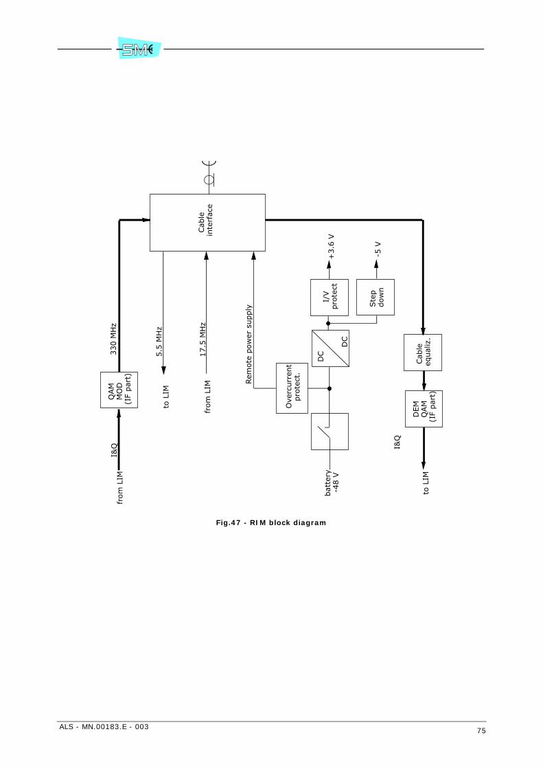
ALS - MN.00183.E - 003 75
Fig.47 - RIM block diagram
Cab
le
inte
rfac
e
Ove
rcurr
ent
pro
tect
.
Rem
ote
pow
er s
upply
5.5
MH
z
QAM
MO
D(I
F par
t)
330 M
Hz
DC
DC
from
LIM
I&Q
bat
tery
-4
8 V
I/V
pro
tect
Ste
p
dow
n
+3.6
V
-5 V
Cab
le
equal
iz.
DEM
QAM
(IF
par
t)
I&Q
to L
IM
17.5
MH
zfr
om
LIM
to L
IM
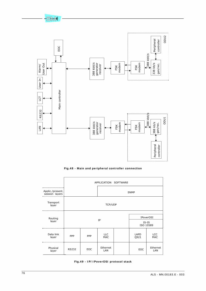
76 ALS - MN.00183.E - 003
Fig.48 - Main and peripheral controller connection
Fig.49 - IP/IPoverOSI protocol stack
Mai
n c
ontr
olle
r
338 k
b/s
388 k
bit/s
LAN
RS232
LCT
Use
r In
Ala
rm/
Use
r O
ut
FSK
modem
FSK
modem
OD
U2
388 k
b/s
388 k
bit/s
FSK
modem
FSK
modem
OD
U1
EO
C
388 k
bit/s
gen
erat
or
rece
iver
388 k
bit/s
gen
erat
or
rece
iver
gen
/rec
.Pe
ripher
alco
ntr
olle
rPe
ripher
alco
ntr
olle
rgen
/rec
.
APPLICATION SOFTWARE
SNMP
TCP/UDP
IPIPoverOSI
IS-ISISO 10589
PPP PPPLLCMAC
LAPDQ921
LCCMAC
RS232 EOCEthernet
LAN EOCEthernet
LAN
Applic./present.session layers
Transportlayer
Routinglayer
Data linklayer
Physicallayer
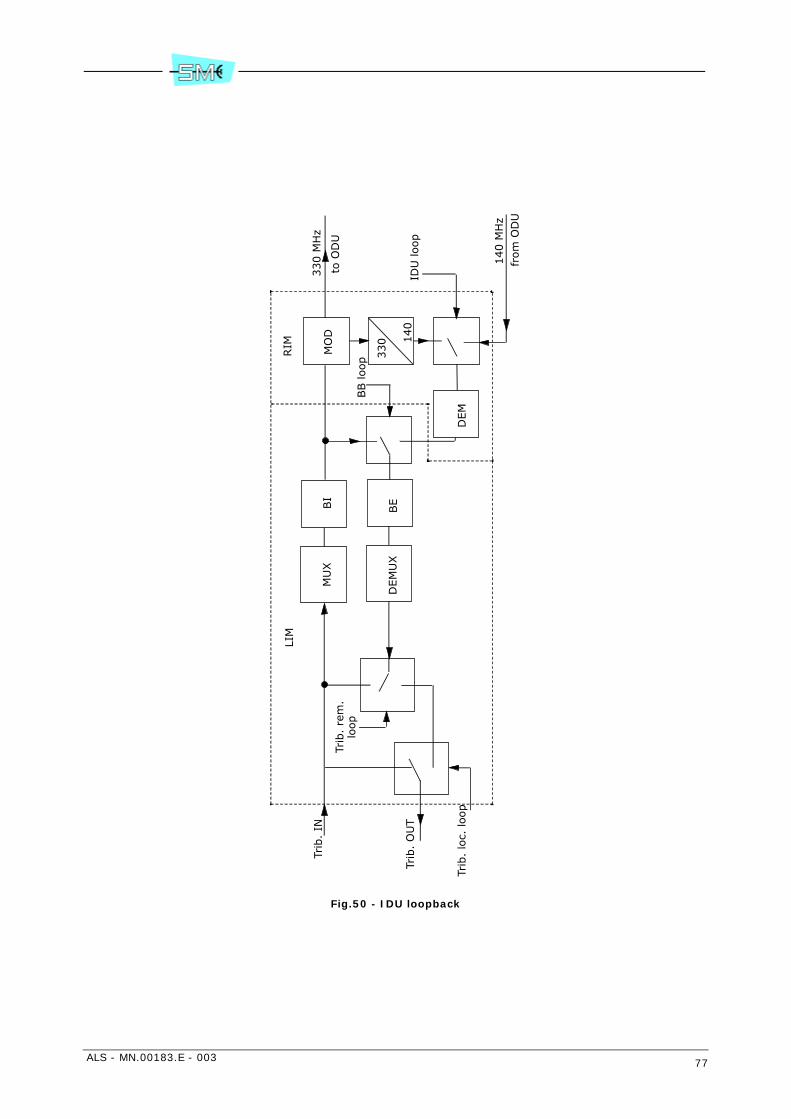
ALS - MN.00183.E - 003 77
Fig.50 - IDU loopback
330 M
Hz
to O
DU
MU
X
BB loop
Trib
. lo
c. loop
Trib
. IN
DEM
UX
BI
BE
MO
D
330 1
40
IDU
loop
140 M
Hz
from
OD
U
Trib
. O
UT
Trib
. re
m.
loop
DEM
LIM
RIM
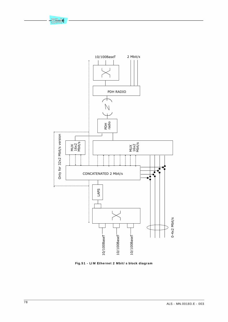
78 ALS - MN.00183.E - 003
Fig.51 - LIM Ethernet 2 Mbit/s block diagram
10/1
00Bas
eT
10/1
00Bas
eT
10/1
00Bas
eT
LAPS
MU
X
16x2
M
bit/s
MU
X
16x2
M
bit/s
CONCATENATED 2 Mbit/s
PDH
ra
dio
PDH RADIO
10/100BaseT 2 Mbit/s
0-4
x2 M
bit/s
Only
for
32x2
Mbit/s
ver
sion
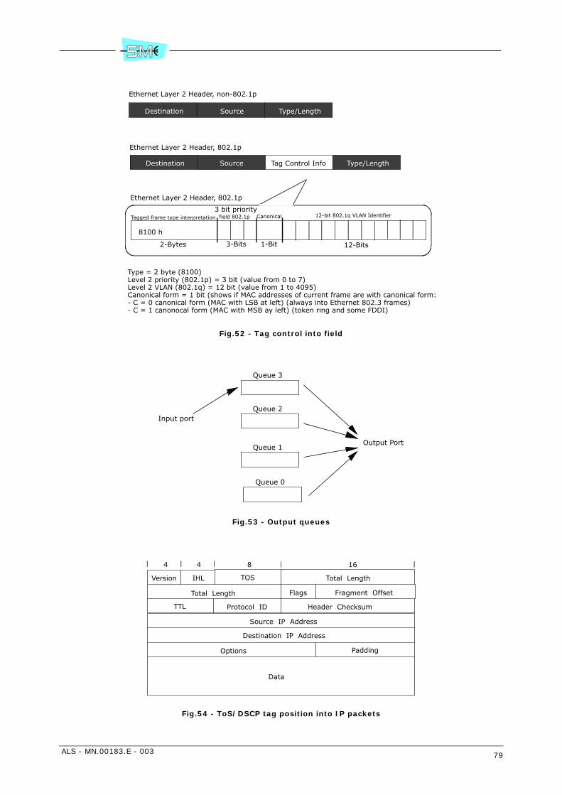
ALS - MN.00183.E - 003 79
Fig.52 - Tag control into field
Fig.53 - Output queues
Fig.54 - ToS/DSCP tag position into IP packets
Ethernet Layer 2 Header, non-802.1p
Destination Source Type/Length
Ethernet Layer 2 Header, 802.1p
Destination Source Tag Control Info Type/Length
8100 h
2-Bytes 3-Bits 1-Bit 12-Bits
Tagged frame type interpretation3 bit priority
field 802.1p Canonical 12-bit 802.1q VLAN Identifier
Ethernet Layer 2 Header, 802.1p
Type = 2 byte (8100)Level 2 priority (802.1p) = 3 bit (value from 0 to 7)Level 2 VLAN (802.1q) = 12 bit (value from 1 to 4095)Canonical form = 1 bit (shows if MAC addresses of current frame are with canonical form:- C = 0 canonical form (MAC with LSB at left) (always into Ethernet 802.3 frames)- C = 1 canonocal form (MAC with MSB ay left) (token ring and some FDDI)
Queue 3
Queue 2
Queue 1
Queue 0
Output Port
Input port
Version TOS Total Length
Total Length Flags Fragment Offset
IHL
TTL Protocol ID Header Checksum
Source IP Address
Destination IP Address
Options Padding
Data
4 4 8 16

80 ALS - MN.00183.E - 003
Fig.55 - ToS/DSCP
0 1 2 3 4 5 6 7
MSB LSB
Not used
Not used
DSCP
ToS
ALS - MN.00183.E - 003 81
10 DESCRIPTION OF THE IDU COMPACT UNIT FOR 2 MBIT/S TRIBUTARIES
10.1 IDU COMPACT 1+0/1+1 VERSION
The IDU Compact unit is made by a single motherboard which contains all the circuit that realize the fol-lowing functionalities:
• line interface
• radio interface
• equipment controller
• IDU loop.
Inside it, we can distinguish the circuits LIM, RIM, CONTROLLER, as described in the chapter regarding theModular IDU.
The IDU Compact is realized in 1+0 version, containing only one RIM, and 1+1 version, containing twoRIMs. The maximum capacity of the IDU Compact is 16x2 Mbit/s.

82 ALS - MN.00183.E - 003
11 DESCRIPTION OF THE IDU COMPACT UNIT FOR 2 MBIT/S TRIBUTARIES AND FOR ETHERNET TRAFFIC
11.1 VERSION IDU COMPACT ETHERNET 1+0/1+1
The compact IDU can be provided with only one optional Ethernet module. In this way, the equipment hasboth 2 Mbit/s port and Ethernet ports and the bit rate assigned to the Ethernet traffic is the rated capacityof the radio decreased by the enabled tributaries.
The module with the Ethernet interface is in alternative to the optional module with the service channelsV11, V28 + RS232.
The IDU Compact Ethernet is equipped with the following tributary interfaces:
• 3 Ethernet 10/100BaseT IEEE 802.3 electrical interfaces
• 16 2 Mbit/s (E1) interfaces.
The total capacity is from 4 to 64 Mbit/s.
For the description of the signal processing at 2 Mbit/s, refer to the chapter 8 DESCRIPTION OF THE MOD-ULAR IDU FOR 2 OR 34 Mbit/s TRIBUTARIES.
For the description of the Ethernet signal processing, refer to chapter 9 DESCRIPTION OF THE MODULARIDU WITH lim ETHERNET (2 Mbit/s TRIBUTARIES + ETHERNET TRAFFIC).
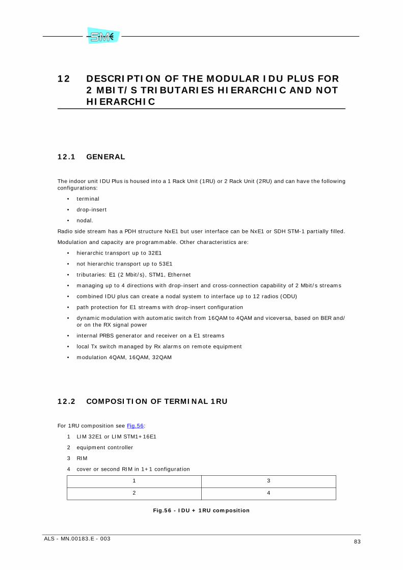
ALS - MN.00183.E - 003 83
12 DESCRIPTION OF THE MODULAR IDU PLUS FOR 2 MBIT/S TRIBUTARIES HIERARCHIC AND NOT HIERARCHIC
12.1 GENERAL
The indoor unit IDU Plus is housed into a 1 Rack Unit (1RU) or 2 Rack Unit (2RU) and can have the followingconfigurations:
• terminal
• drop-insert
• nodal.
Radio side stream has a PDH structure NxE1 but user interface can be NxE1 or SDH STM-1 partially filled.
Modulation and capacity are programmable. Other characteristics are:
• hierarchic transport up to 32E1
• not hierarchic transport up to 53E1
• tributaries: E1 (2 Mbit/s), STM1, Ethernet
• managing up to 4 directions with drop-insert and cross-connection capability of 2 Mbit/s streams
• combined IDU plus can create a nodal system to interface up to 12 radios (ODU)
• path protection for E1 streams with drop-insert configuration
• dynamic modulation with automatic switch from 16QAM to 4QAM and viceversa, based on BER and/or on the RX signal power
• internal PRBS generator and receiver on a E1 streams
• local Tx switch managed by Rx alarms on remote equipment
• modulation 4QAM, 16QAM, 32QAM
12.2 COMPOSITION OF TERMINAL 1RU
For 1RU composition see Fig.56:
1 LIM 32E1 or LIM STM1+16E1
2 equipment controller
3 RIM
4 cover or second RIM in 1+1 configuration
Fig.56 - IDU + 1RU composition
1 3
2 4
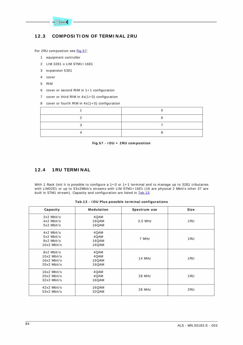
84 ALS - MN.00183.E - 003
12.3 COMPOSITION OF TERMINAL 2RU
For 2RU composition see Fig.57:
1 equipment controller
2 LIM 32E1 o LIM STM1+16E1
3 expansion 53E1
4 cover
5 RIM
6 cover or second RIM in 1+1 configuration
7 cover or third RIM in 4x(1+0) configuration
8 cover or fourth RIM in 4x(1+0) configuration
Fig.57 - IDU + 2RU composition
12.4 1RU TERMINAL
With 1 Rack Unit it is possible to configure a 1+0 or 1+1 terminal and to manage up to 32E1 tributarieswith LIM32E1 or up to 53x2Mbit/s streams with LIM STM1+16E1 (16 are physical 2 Mbit/s other 37 arebuilt in STM1 stream). Capacity and configuration are listed in Tab.13.
Tab.13 - IDU Plus possible terminal configurations
1 5
2 6
3 7
4 8
Capacity Modulation Spectrum use Size
2x2 Mbit/s4x2 Mbit/s5x2 Mbit/s
4QAM16QAM16QAM
3,5 MHz 1RU
4x2 Mbit/s5x2 Mbit/s8x2 Mbit/s10x2 Mbit/s
4QAM4QAM16QAM16QAM
7 MHz 1RU
8x2 Mbit/s10x2 Mbit/s16x2 Mbit/s20x2 Mbit/s
4QAM4QAM16QAM16QAM
14 MHz 1RU
16x2 Mbit/s20x2 Mbit/s32x2 Mbit/s
4QAM4QAM16QAM
28 MHz 1RU
42x2 Mbit/s53x2 Mbit/s
16QAM32QAM
28 MHz 2RU

ALS - MN.00183.E - 003 85
12.5 2RU TERMINAL
With 2 unit IDU Plus it is possible to manage up to 53 tributaries E1 with the following configurations:
• terminal 1+0
• terminal 1+1
• terminal 2x (1+0)
12.6 2 Mbit/s TRIBUTARY INTERFACE
The 2 Mbit/s tributary interface is 75 Ohm or 120 Ohm. Both interfaces are present into the front panelconnectors the user can select the interface to use, preparing in the correct way the relevant cabling.
12.7 MATRIX STM1+16E1 (1RU and 2RU)
Matrix module provides 16x2 Mbit/s interfaces and one SDH STM1 port. STM1 port is protected by twoSTM1 interfaces that can be available electrical or optical (different 2 plug-in modules).
STM1 is terminated and the contained E1 streams are sent to switch matrix, where E1 streams can be re-directed towards radio link, towards 2 Mbit/s interface or remapped into STM-1, or by means of NBUS to-wards other IDUs equipped with Matrix. Modular IDU Plus is operating in MST mode and has a completeSETS synchronisation circuit with input and output synchronisation signals.
Maximum capacity of LIM STM1+16E1 is:
• 53E1 for terminal 1+0
• 53E1 for terminal 1+1
• 79E1 for terminal 2x(1+0).
12.8 DROP-INSERT (2RU)
For 2RU subrack composition see Fig.57:
1 equipment controller
2 processor 53E1
3 matrix 32E1
4 processor 53E1
5 RIM
6 cover or second RIM in 1+1 configuration
7 cover or third RIM in 4x(1+0) configuration
8 cover or fourth RIM in 4x(1+0) configuration.
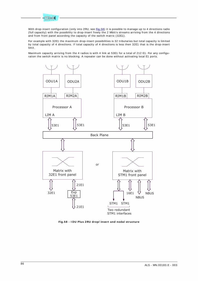
86 ALS - MN.00183.E - 003
With drop-insert configuration (only into 2RU, see Fig.58) it is possible to manage up to 4 directions radio(full capacity) with the possibility to drop-insert freely the 2 Mbit/s streams arriving from the 4 directionsand from front panel according the capacity of the switch matrix (32E1).
For example with 32E1 the maximum drop-insert possibilities is 32 tributaries but total capacity is limitedby total capacity of 4 directions. If total capacity of 4 directions is less then 32E1 that is the drop-insertlimit.
Maximum capacity arriving from the 4 radios is with 4 link at 53E1 for a total of 212 E1. For any configu-ration the switch matrix is no blocking. A repeater can be done without activating local E1 ports.
Fig.58 - IDU Plus 2RU drop/insert and nodal structure
ODU1A ODU2A
RIM1A RIM2A
Processor A
LIM A
53E1 53E1
ODU1B ODU2B
RIM1B RIM2B
Processor B
LIM B
53E1 53E1
Back Plane
Matrix with32E1 front panel
Matrix withSTM1 front panel
32E1
21E1
Exp53E1
21E1STM1 STM1
16E1NBUS
NBUS
Two redundant STM1 interfaces
or

ALS - MN.00183.E - 003 87
12.9 NODAL (UP TO 3X2RU)
Composition of nodal is similar to drop-insert (see Fig.57):
1 equipment controller
2 processor 53E1
3 1+0 matrix node STM1+16E1, 1+1 matrix STM-1 +16E1, 2x(1+0) matrix STM1 + 16E1
4 processor 53E1
5 RIM
6 cover or RIM
7 cover or RIM
8 cover or RIM
A node can be made up of up to 3 subracks of 2RU so that we can have up to 12 maximum independentradio directions.
On the front panel of the STM1+16E1 matrix there are two “NBUS” ports (1 and 2) which must be con-nected to other one or two 2RU subracks as in Fig.59 and Fig.60.
The connection among the subracks are made by cables of CAT7 quality, SIAE code F03471 length 75 cm,to insert into the NBUS connectors (1 and 2) on the front panel.
Each subrack must be defined as NodeA, NodeB or NodeC. The cables among the NBUS must be connectedonly as in Fig.59 and Fig.60.
NBUS can operate in Protected modality or in Not Protected modality. Each NBUS carries 126 E1’s. In caseof Not Protected modality, all the 126 E1’s of the NBUS are used to connect a subrack to the other for atotal amount of 252 E1 connections available on the NBUS.
In case of Protected modality, the unused connections, for example between node A (NBUS1) and node B(NBUS1) are used as protection of the connections between node A (NBUS1) and node B (NBUS1); forexample 63 E1’s are used between node A and node B and the other 63 E1’s are used as protection of theconnections between node A and node C, the connections used as protection pass from node B in pass-through modality without need of programming.
Warning: for the best operation of the protected modality, it is necessary to choose the shortest path aspreferential connection; for example, for the connections between A and B choose the connections betweenA and B as preferential; for the connection between A and C choose the connections between A and C aspreferential.
In case of protected modality, the system displays, by means of the SCT/LCT program in the cross-con-nection window, only the NBUS with 126 E1’s (subdivided in two parts for a better graphic display). Theunused E1 ports are automatically programmed as pass-through between NBUS1 and NBUS2 but theseconnections are not displayed in SCT/LCT.
In case of unprotected modality, the system displays, by means of the SCT/LCT program in the cross-con-nection window, the NBUS1 and NBUS2 buses each one with 126 E1’ (subdivided in two parts for a bettergraphic display).
The troubles in the connections between the NBUS buses are signalled by alarms.
In case of protected modality, if the cable carrying the traffic is broken, an alarm is issued on the relevantNBUS port, the equipment software switches the traffic on the other operating NBUS cable.
12.9.1 Expansion from 2 to 3 nodes
Suppose that the nodes A and B already exist and that you must add the node C. Disconnect the cablebetween NBUS2 node A and NBUS2 node B, the traffic is automatically switched to the other cable, if nec-essary.
By SCT/LCT, re-program the nodes A and B as nodes with 3 items.
By SCT/LCT, re-program the node C as nodeC, protected and define the node with 3 items.
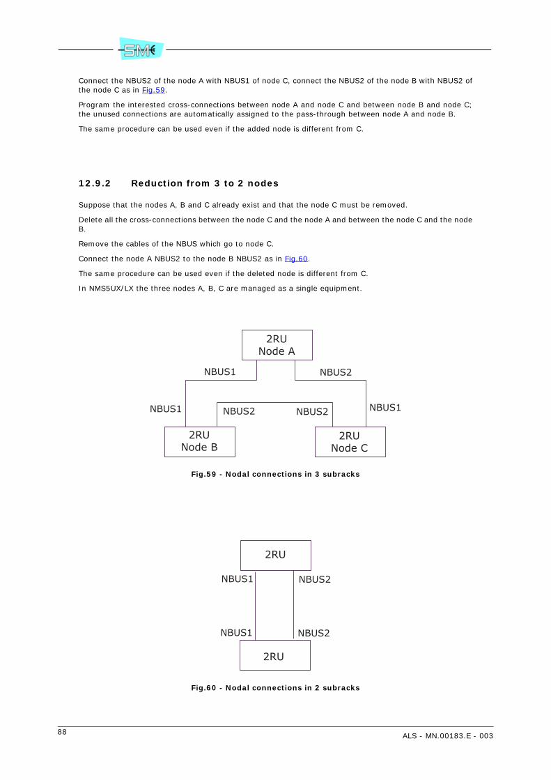
88 ALS - MN.00183.E - 003
Connect the NBUS2 of the node A with NBUS1 of node C, connect the NBUS2 of the node B with NBUS2 ofthe node C as in Fig.59.
Program the interested cross-connections between node A and node C and between node B and node C;the unused connections are automatically assigned to the pass-through between node A and node B.
The same procedure can be used even if the added node is different from C.
12.9.2 Reduction from 3 to 2 nodes
Suppose that the nodes A, B and C already exist and that the node C must be removed.
Delete all the cross-connections between the node C and the node A and between the node C and the nodeB.
Remove the cables of the NBUS which go to node C.
Connect the node A NBUS2 to the node B NBUS2 as in Fig.60.
The same procedure can be used even if the deleted node is different from C.
In NMS5UX/LX the three nodes A, B, C are managed as a single equipment.
Fig.59 - Nodal connections in 3 subracks
Fig.60 - Nodal connections in 2 subracks
2RUNode A
2RUNode B
2RUNode C
NBUS1
NBUS1 NBUS2
NBUS2
NBUS1NBUS2
2RU
2RU
NBUS2
NBUS2
NBUS1
NBUS1
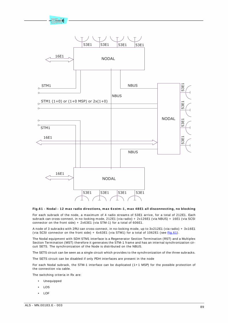
ALS - MN.00183.E - 003 89
Fig.61 - Nodal - 12 max radio directions, max 6xstm-1, max 48E1 all disconnecting, no blocking
For each subrack of the node, a maximum of 4 radio streams of 53E1 arrive, for a total of 212E1. Eachsubrack can cross-connect, in no-locking mode, 212E1 (via radio) + 2x126E1 (via NBUS) + 16E1 (via SCSIconnector on the front side) + 2x63E1 (via STM-1) for a total of 606E1.
A node of 3 subracks with 2RU can cross-connect, in no-locking mode, up to 3x212E1 (via radio) + 3x16E1(via SCSI connector on the front side) + 6x63E1 (via STM1) for a total of 1062E1 (see Fig.61).
The Nodal equipment with SDH STM1 interface is a Regenerator Section Termination (RST) and a MultiplexSection Termination (MST) therefore it generates the STM-1 frame and has an internal synchronization cir-cuit SETS. The synchronization of the Node is distributed on the NBUS.
The SETS circuit can be seen as a single circuit which provides to the synchronization of the three subracks.
The SETS circuit can be disabled if only PDH interfaces are present in the node
For each Nodal subrack, the STM-1 interface can be duplicated (1+1 MSP) for the possible protection ofthe connection via cable.
The switching criteria in Rx are:
• Unequipped
• LOS
• LOF
NODAL
53E1 53E1
16E1
53E1 53E1
NODAL
53E1 53E1
16E1
53E1 53E1
NODAL
53E1
53E1
53E1
53E1
16E1
NBUS
STM1
STM1 (1+0) or (1+0 MSP) or 2x(1+0)
STM1
NBUS
NBUS
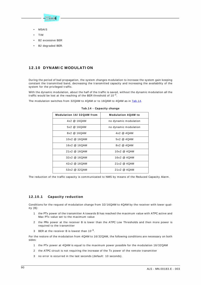
90 ALS - MN.00183.E - 003
• MSAIS
• TIM
• B2 excessive BER
• B2 degraded BER.
12.10 DYNAMIC MODULATION
During the period of bad propagation, the system changes modulation to increase the system gain keepingconstant the transmitted band, decreasing the transmitted capacity and increasing the availability of thesystem for the privileged traffic.
With the dynamic modulation, about the half of the traffic is saved, without the dynamic modulation all thetraffic would be lost at the reaching of the BER threshold of 10-3.
The modulation switches from 32QAM to 4QAM or to 16QAM to 4QAM as in Tab.14.
Tab.14 - Capacity change
The reduction of the traffic capacity is communicated to NMS by means of the Reduced Capacity Alarm.
12.10.1 Capacity reduction
Conditions for the request of modulation change from 32/16QAM to 4QAM by the receiver with lower qual-ity (B):
1 the PTx power of the transmitter A towards B has reached the maximum value with ATPC active andMax PTx value set to the maximum value
2 the PRx power at the receiver B is lower than the ATPC Low Thresholds and then more power isrequired to the transmitter
3 BER at the receiver B is lowest than 10-9.
For the restore of the modulation from 4QAM to 16/32QAM, the following conditions are necessary on bothsides:
1 the PTx power at 4QAM is equal to the maximum power possible for the modulation 16/32QAM
2 the ATPC circuit is not requiring the increase of the Tx power of the remote transmitter
3 no error is occurred in the last seconds (default: 10 seconds).
Modulation 16/32QAM from Modulation 4QAM to
4x2 @ 16QAM no dynamic modulation
5x2 @ 16QAM no dynamic modulation
8x2 @ 16QAM 4x2 @ 4QAM
10x2 @ 16QAM 5x2 @ 4QAM
16x2 @ 16QAM 8x2 @ 4QAM
21x2 @ 16QAM 10x2 @ 4QAM
32x2 @ 16QAM 16x2 @ 4QAM
42x2 @ 16QAM 21x2 @ 4QAM
53x2 @ 32QAM 21x2 @ 4QAM

ALS - MN.00183.E - 003 91
Note: If maximum PTx at 4QAM is 20dBm and the maximum PTx at 16QAM is 15dBm then the differenceis 5dB the PTx Boost value can be from 0 to 5dB. If the ATPC values are not correct, the dynamic modu-lation is not activated.
The Performance Monitoring are reported as 16QAM. The AIS on the tributaries is not available.
The Upgrade of equipment already installed can be executed by means of the simple download from thesupervision network.
12.10.2 Setting with SCT/LCT
A green light signal shows that the dynamic modulation is active, the orange light signal signals that thereduction of modulation is active: in this case the Reduced Capacity Alarm is active.
Warning: no configuration change must be made when the Dynamic Modulation is active. In detail, if a loopmust be executed, first deactivate the Dynamic Modulation.
PTx Boost: increase of PTx power with reduced modulation, default 5Db Receiving Hysteresis: number ofdB from the Prx level with BER 10-9, default 2dB.
Atpc Hysteresis for recovering: hysteresis of Atpc from the restore of 16QAM, default 0dB.
Recovering timeout: seconds with PRx level stable before the restore of the 16QAM modulation, default10sec.
Tx power Overboost: increase of the Tx power of 3dB with 16QAM modulation. Enable only if allowed bythe laws of Your country.
12.11 LIM
The LIM performs the following operations:
• multiplexing process of the input tributaries
• aggregation of the multiplexed signals along with services through a Bit Insertion circuit
• processing in digital form of the baseband part of the QAM modulator (the IF part of the QAM mod-ulator takes place within the RIM)
• duplication of the digital processed signal to supply two RIMs in 1+1 versions. In the full duplicatedversion the changeover occurs at tributary level.
Different baseband structures and digital processing of the signal to be forwarded to the QAM modulator/demodulator is produced by a “chip set”. Controls to the chip set and status/alarm reporting from the chipset are given/received by main controller within the CONTROLLER module.
12.12 CIRCUIT DESCRIPTION
Tx side
Refer to Fig.62.
The 2 Mbit/s input signal is code converted from HDB3 to NRZ format before being multiplexed. The mul-tiplexing scheme depends on the number and the bit rate of the input tributaries.
In addition to the tributary mux, an additional service mux is provided for aggregation of various servicesignals interfaced by Equipment Controller module.

92 ALS - MN.00183.E - 003
The multiplexed tributary and service signals are then sent to the B.I. for aggregate frame generation oc-curring at the bit rate depending on various versions implemented.
The aggregate frame contains:
• the main signal from the MUX(s)
• the framed service signal from the service MUX
• the EOC signals for supervision message propagation towards the remote equipment
• the frame alignment word
• the bits dedicated to the FEC.
All the synch. signals to perform multiplexing (demultiplexing) and BI (BE) process are achieved from a x0at 48 MHz
The LIM also includes the processing in digital form (see Fig.62) of the modulating signal to be sent to themixers of the QAM modulator within the RIM.
The digital process includes:
• serial to parallel conversion
• differential encoding
• generation of the shaped modulating signals I and Q to be sent to each individual RIM.
Rx side
Refer to Fig.63.
From the two RIMs the LIM is receiving the I and Q analogue signals then digital converted for the followingprocessing:
• clock recovery
• frequency and phase carrier locking
• baseband equalisation and filtering
• bit polarity decision
• differential decoding
• parallel to serial conversion to recover the aggregate signal at the receive side.
The aggregate signal is then sent to a frame alignment circuit and CRC analysis and then to the error cor-rector. The errors uncorrected by the FEC are properly counted to achieve:
• BER estimate measurement
• radio performances
HBER/LBER/Early Warning Alarm roots for monitoring purpose and Rx switching operation are taken di-rectly from CRC circuit before FEC correction.
The Rx switching receives the two aggregate signals and performs signal selection under the control of alogic circuit according with Tab.15.
The changeover is hitless and the system has built in capabilities of minimising the passed errors duringthe detection time, such as the early warning criteria. The hitless switching facility provides automatic syn-chronisation of the two incoming streams up to a dynamic difference of ± 7 bits; additionally, the switchingunit is also capable of compensating static delays between the two incoming streams of up to ±7 bits. Atthe output of the Rx switch the Bit Extraction separates the main signal from the services and then, aftera proper demultiplexing process as previously described, sends them to the output interface lines.

ALS - MN.00183.E - 003 93
Tab.15 - Switching priority
12.13 RIM
Refer to Fig.64.
The RIM consists of the following main circuits:
• IF part of the QAM modulator
• IF part of the QAM demodulator
• power supply
• telemetry IDU/ODU
There are two types of RIM according to modulation capability:
• 4QAM/16QAM or
• 4QAM/16QAM/32QAM
Inside the RIM, behind the front panel, the is a fuse for protection to whole IDU. It is a soldering type fuse.
Priority Levels Description
Highest|||||||||||||||||||||||||↓
Lowest
Priority 1 RIM PSU Alarm
Priority 2 Manual forcing (from main controller)
Priority 3 Cable Short Alarm
Priority 3 Cable Open Alarm
Priority 3 IF Unit Alarm
Priority 3 Demodulator Failure
Priority 3 Base Band Unit Failure Alarm
Priority 3 ODU Unit Failure
Priority 3 ODU PSU Alarm
Priority 3 VCO Failure Alarm
Priority 3 High BER >10–3 (or 10–4 or 10–5, selectable by software)
Priority 4 Low BER > 10–6 (or 10–7 or 10–8, selectable by software)
Priority 5Early Warning BER > 10–9 (or 10–10 or 10–11 or 10–12, select-
able by software)
Priority 6RF Input Low (Rx threshold SW selectable from –40 to –99
dBm)
Priority 7 CRC Pulse
Priority 8 Revertive Rx (branch one preferential)

94 ALS - MN.00183.E - 003
12.13.1 QAM modulator
I and Q signals from LIM are connected to a 4/16/32QAM programmable modulator. It consists of the fol-lowing circuits:
• recovery low pass filter to eliminate signal periodicity
• two mixers for carrier amplitude and phase modulation process
• 330 MHz local oscillator
• a 90° phase shifter to supply two mixers with two in quadrature carriers
• a combiner circuit to generate the QAM modulation
The thus obtained 330 MHz QAM modulated carrier is then sent to the cable interface for connection withODU.
12.13.2 QAM demodulator
At the receive side, from the cable interface, the 140 MHz QAM modulated carrier is sent to the QAM de-modulator passing through a cable equalizer circuit. The QAM demodulator within the RIM extracts the Iand Q signals to be sent to the digital part of the demodulator within the LIM.
12.13.3 Power supply
The –48 V battery voltage feeds the IDU and ODU circuitry. The service voltages for the IDU feeding areachieved through a DC/DC converter for +3.6 V generation and a step down circuit for –5V.
Both voltages are protected against overvoltages and overcurrents.
The power to the ODU is given by the same battery running through the interconnection cable.
An electronic breaker protects the module and the battery against cable failure. Protections are automat-ically restored. Overcurrent or missing current on IDU-ODU cable are detected by Cable short and Cableopen alarm.
12.13.4 Telemetry IDU/ODU
The dialogue IDU/ODU is made–up by the main controller and associated peripherals within the ODU. Con-trols for ODU management and alarm reporting is performed making use of a bidirectional 388 kbit/sframed signals. The transport along the interconnecting cable is carried out via two FSK modulated carri-ers: 17.5 MHz from IDU to ODU; 5.5 MHz from ODU to IDU.
12.14 EQUIPMENT CONTROLLER
The Equipment Controller module performs the following:
• interfaces the service signals
• houses the equipment software for equipment management
• interfaces the SCT/LCT program through supervision ports

ALS - MN.00183.E - 003 95
• receive external alarms and route them to relay contacts along with the internal alarms generatedby the equipment.
Warning: lithium battery inside, refer to national rules for disposal.
12.14.1 Service signals
The Equipment Controller offers an electrical interface to the following three service channel options:
• 9600 baud/V28 with digital party line or in alternative 2x4800 baud/V28 – 9600 baud V28/RS232synchronous/asynchronous channels
• 64 kbit/s/V11 codirectional or contradirectional
• 2 Mbit/s wayside G.703 (not available in no-hierarchical configurations).
The service channels thus interfaced are then sent to the LIM for MUX/DEMUX processing.
12.14.2 Equipment software
Equipment software permits to control and manage all the equipment functionality. It is distributed on twohardware levels: main controller and ODU peripheral controllers.
The dialogue between main and peripheral controllers is shown in Fig.65.
Main controller
The activities executed by the main controller are the following:
• Communication management: it makes use of SNMP as management protocol and IP or IP over OSIas communication protocol stacks. See Fig.66 for details. The interface ports for the equipmentmanagement are the following:
- LAN Ethernet 10BaseT/10Base2 or AUI
- USB port for 1+0 version
- RS232 asynchronous used for SCT/LCT connection (if USB connector is not used) or with otherNE
- EOC embedded within the PDH radio frame for connection to the remote NEs
- EOC embedded within the 2 Mbit/s tributary G.704 frame.
• Log–in: the main controller manages the equipment or network login/logout by setting and thencontrolling the user’s ID and relevant password.
• Database (MIB): validation and storing in a non–volatile memory of the equipment configurationparameters.
• Equipment configuration: distribution of the parameters stored in the MIB towards the peripheralµPs for their actuation in addition to the controls from user not stored in the MIB (i.e. loops, manualforcing etc...).
• Alarm monitoring: acquisition, filtering and correlation of the alarms gathered from slaved µPs. Lo-cal logger and alarm sending to the connected managers: SCT/LCT – NMS5UX. Management of thealarm signalling on the LIM front panel.
• Performances: PM management as per Recc. G.828.
• Download: the main controller is equipped with two flash memory banks containing the running pro-gram (active bank) and the stand–by program (inactive bank). This permits to download a new soft-ware release to the inactive bank without distributing the traffic.Bank switch enables the new release to be used.

96 ALS - MN.00183.E - 003
Download activity is based on FTP protocol which downloads application programs, FPGA configu-ration, configuration files on main controller inactive bank or directly on the peripheral controllers.
Peripheral controllers
The peripheral controllers take place within the ODU and are slaved to main controller with the task of ac-tivating controls and alarm reporting of dedicated functionality.
12.14.3 Supervision ports
The equipment management is made by SCT/LCT program through the supervision ports.
The following are made available:
• LCT (USB) and RS232 interface with PPP protocol
• LAN interface using IP or IPoverOSI protocols; two LAN interfaces are connected with a “all-pass”switch
• EOC (Embedded Overhead Channel) using a 64 kbit/s slot of the radio frame to broadcast the su-pervision messages towards the remote terminals. The protocol used is IP or IPoverOSI.
12.15 IDU LOOPS
To control the IDU correct operation a set of local and remote loops are made available. The commandsare forwarded by the LCT/SCT program. Loop block diagram is shown by Fig.67.
12.15.1 Tributary loop
Tributary local loop
Each input tributary is routed directly to the trib. output upon receiving the command from the LCT. TheTx line transmission is still on.
Tributary remote loop
Each tributary directed towards the Rx output line is routed back to the Tx line. The Rx line is still on.
12.15.2 Baseband unit loop
This kind of loop is only local and is activated at BI/BE level. The Tx line is still on.

ALS - MN.00183.E - 003 97
12.15.3 IDU loop
This kind of loop permits to check the full IDU operation. When activated, the modulator output is connect-ed to demodulator input. The loop is assured by converting the frequency of the modulator from 330 MHzto 140 MHz.
12.16 EXPANSION 53E1
This board can be used in a 2RU in position 3 together with LIM 32E1 to provide the interfaces necessaryto connect up to 53E1.
12.17 SERVICE CHANNEL ADAPTER
This board can be used in a 2RU in position 3 together with LIM 32E1.
This board gives the interface to service channels CH1 and CH2 plus 2 Mbit/s wayside channel. To be usedwhen there are no matrix and no expansion 53E1.
12.18 PROCESSOR 53E1
The 53E1 processor has the same functionnality of LIM but doesn’t have the front panel connector becauseall 53E1 are sent to Matrix.

98 ALS - MN.00183.E - 003
Fig.62 - LIM block diagram - Tx side
Code
conve
rter
Code
conve
rter
Code
conve
rter
MU
X
2x2
/4x2
8x2
/16x2
32x2
/5x2
10x2
/21x2
42x2
/53x2
Mbit/s
Ser
vice
ch
annel
m
odule
Contr
olle
r m
odule
BI:
- m
ain t
raffic
- se
rvic
es-
EO
C-
FEC
- FA
W
Fram
egen
erat
or
Dig
ital
MO
D-
S/P
conve
rtio
n-
diff. e
nco
din
g-
modula
ting
signal
gen
erat
ion
X0 4
8 M
Hz
D/A
D/A
to R
IM2
to R
IM1
I&Q
I&Q
synch
r.
2/3
4 M
bit/s
G.7
03
nx2 . . .
nx3
4
2 M
bit/s
way
side
serv
ices
only
(16x2
or
hig
her
spee
dNRZ
CK
NRZ
CK
NRZ
CK
- FS
K m
od/d
emod
- 388 fra
me
gen
erat
or/
rece
iver
to/f
rom
mai
n
contr
olle
r

ALS - MN.00183.E - 003 99
Fig.63 - LIM block diagram - Rx side
A
D-
Ck
reco
very
- Car
rier
lock
- Equal
iz.
& filt
.-
Dec
isio
n
- D
iff. d
ecod.
- S/P
CRC
anal
ysis
& a
ligner
FEC
- BER e
xtim
ates
- H
igh B
ER
- Lo
w B
ER
- EW
SW
lo
gic
from
m
ain
µP
switch
co
ntr
ols
sam
e as
ab
ove
I&Q
fr
om
RIM
1
I&Q
fro
m
RIM
2
BE
DEM
UX
2x2
/4x2
8x2
/16x2
32x2
/5x2
10x2
/21x2
42x2
/53x2
Mbit/s
Ser
vice
chan
nel
DEM
UX
Code
conve
rter
Code
conve
rter
Code
conve
rter
Contr
olle
r m
odule
2 M
bit/s
G.7
03
nx2
Mbit/s
Ser
vice
s
BER m
eas.
P.M
.
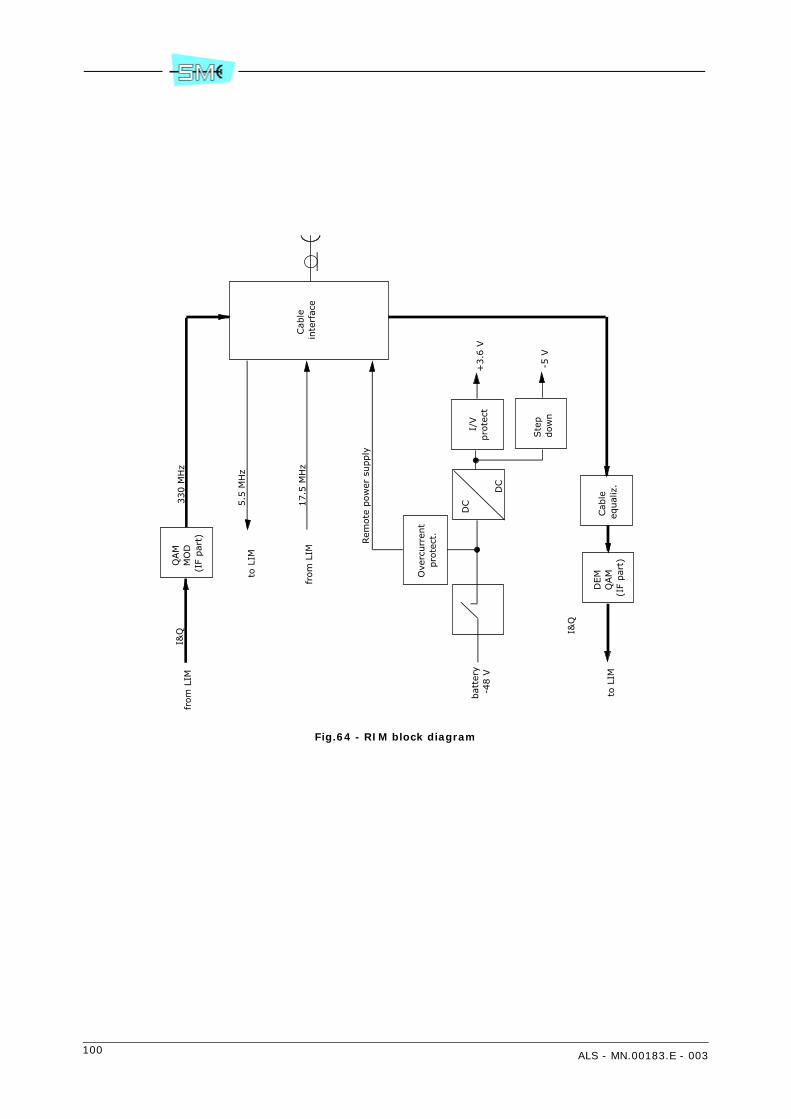
100 ALS - MN.00183.E - 003
Fig.64 - RIM block diagram
Cab
le
inte
rfac
e
Ove
rcurr
ent
pro
tect
.
Rem
ote
pow
er s
upply
5.5
MH
z
QAM
MO
D(I
F par
t)
330 M
Hz
DC
DC
from
LIM
I&Q
bat
tery
-4
8 V
I/V
pro
tect
Ste
p
dow
n
+3.6
V
-5 V
Cab
le
equal
iz.
DEM
QAM
(IF
par
t)
I&Q
to L
IM
17.5
MH
zfr
om
LIM
to L
IM
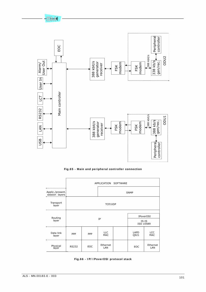
ALS - MN.00183.E - 003 101
Fig.65 - Main and peripheral controller connection
Fig.66 - IP/IPoverOSI protocol stack
Mai
n c
ontr
olle
r
338 k
b/s
388 k
bit/s
LAN
RS232
LCT
Use
r In
Ala
rm/
Use
r O
ut
FSK
modem
FSK
modem O
DU
2
388 k
b/s
388 k
bit/s
FSK
modem
FSK
modem O
DU
1
EO
C
388 k
bit/s
gen
erat
or
rece
iver
388 k
bit/s
gen
erat
or
rece
iver
gen
/rec
.Pe
ripher
alco
ntr
olle
rPe
ripher
alco
ntr
olle
rgen
/rec
.
USB
APPLICATION SOFTWARE
SNMP
TCP/UDP
IPIPoverOSI
IS-ISISO 10589
PPP PPPLLCMAC
LAPDQ921
LCCMAC
RS232 EOCEthernet
LAN EOCEthernet
LAN
Applic./present.session layers
Transportlayer
Routinglayer
Data linklayer
Physicallayer

102 ALS - MN.00183.E - 003
Fig.67 - IDU loopback
330 M
Hz
to O
DU
MU
X
BB loop
Trib
. lo
c. loop
Trib
. IN
DEM
UX
BI
BE
MO
D
330 1
40
IDU
loop
140 M
Hz
from
OD
U
Trib
. O
UT
Trib
. re
m.
loop
DEM
LIM
RIM

ALS - MN.00183.E - 003 103
13 DESCRIPTION OF THE IDU COMPACT PLUS FOR 2 MBIT/S TRIBUTARIES AND ETHERNET TRAFFIC
13.1 IDU COMPACT PLUS ETHERNET 1+0/1+1 VERSION
The IDU Compact Plus can be provided with optional Ethernet tributary interface. In this way, the equip-ment has both 2 Mbit/s ports and the Ethernet ports, and the bit rate assigned to the Ethernet traffic is therated capacity of the radio decreased by the enabled tributaries.
The IDU Compact Plus is equipped with the following interfaces:
• 3 Ethernet 10/100BaseT IEEE 802.3 electrical interfaces
• 32 2Mbit/s (32xE1) interfaces.
For the description of the processing of the 2Mbit/s signals, refer to the description of the IDU Plus.
For the description of the processing of the Ethernet signals, refer to the description of the IDU ModularEthernet.
The IDU Compact Plus with Ethernet tributary is realized in terminal configuration.
The transmission capacity is displayed in Tab.16.
Tab.16 - Transmission capacity of the IDU Compact Plus with Ethernet
Fig.68 - Compact IDU PLUS 1+1 (32E1 + 3ETH)
64 Mbit/s 2/4/5/8/10/16/21/32 E1 + 3x10/100BaseT 1+0/1+1
105 Mbit/s 2/4/5/8/10/16/21/32 E1 + 3x10/100BaseT 1+0/1+1
1
12 2
RS232V11
Q3/2 Q3/1 LCT USER IN/OUT
RXTX12
TESTALR
Trib. 1-8 Trib. 9-16
Trib. 25-32Trib. 17-24
21
+ - -+48VDC 48VDC
PS
1 2
250VACM 3.15A3.15AM 250VAC
10/100 BaseT
1 2 3ACT LINK
DPX

104 ALS - MN.00183.E - 003
14 DESCRIPTION OF THE MODULAR IDU FOR E/W REPEATER WITH DROP/INSERT
14.1 GENERAL
Description that follows covers indoor unit for East/West repeater with Ring Protection.
Paragraph 14.2 COMPOSITION deals with unit composition because number and type of modules are dif-ferent respect a standard IDU.
Paragraph 14.3 IDU CHARACTERISTICS deals with an explanation of unit block diagrams and with a de-scription of functions performed by each module.
14.2 COMPOSITION
Indoor unit for East/West repeater with Drop/Insert functionalities is made up with the following modules:
- D12052–02 Processor unit (2: East, West)
- D12089 Crossconnection matrix
- D12094 Controller
- D12037 RIM (2: East, West)
Fig.69 - IDU for E/W repeater
RIMRIM
12
21
RIMRIM
FAIL
FAIL
Q3WAYA
LCT USER IN/OUTRS232 CH1 CH2 2Mb/s
SIDE
RXTX
REMTEST
ODUIDU
16151413121110987654321FAIL
D12052-02 D12089 D12037
D12094
East
West
ALS - MN.00183.E - 003 105
14.3 IDU CHARACTERISTICS
14.3.1 Management of tributaries
A 2 Mbit/s tributary can be managed by cross connection matrix in different ways:
• Ring Protection – A tributary is inserted (transmitted) in radio aggregate frame towards both direc-tion and can be dropped (received) from one direction or from the other depending on cross con-nection and E1 switch criteria
• Pass through – IDU works as repeater, tributary coming from one direction is sent to the other
• Loop – E1 accessing the matrix from East side or West side can be looped back towards its origin.
14.3.2 Capacity
IDU max capacity depends on modulation used:
• 16QAM – max capacity is 32x2 Mbit/s with maximum 16 tributaries with protected connections(Drop/Insert). Lower capacity can be set.
• 4QAM – max capacity is 16x2 Mbit/s and in this configuration all tributaries can be set in DropInsertor in Pass through (in this last configuration the three sides of the matrix have the same capacity:16x2 Mbit/s). Lower capacity can be set.
System can work with one branch capacity different than the other.
14.3.3 E1 switching criteria
In network configuration where thus East/West repeater IDU is employed as a Ring Protection, where adirection protects the other on the opposite direction, the E1 drop can be managed through suitable E1switching criteria:
1 Manual forcing
2 2 Mbit/s G.704 alarms (AIS, OOF, OOMF, BER6) where:
- AIS: presence of AIS
- OOF: out of E1 frame
- OOMF: out of E1 multiframe
- BER6: BER = 10–6
3 Preferential.
14.4 CIRCUIT DESCRIPTION
Description that follows is referring to MATRIX/PROCESSOR/CONTROLLER/RIM module the IDU consists of.

106 ALS - MN.00183.E - 003
14.4.1 Matrix
Matrix module presents on front panel the 2 Mbit/s connectors and contains the sixteen relevant electricalinterface and the cross connection matrix.
The matrix allows connections of 2 Mbit/s streams with following capacities and directions:
• east side – 32x2 Mbit/s, subdivided from 1 to 16 one at a time and from 17 to 32 framed inside a34368 kbit aggregate
• west side – 32x2 Mbit/s, subdivided from 1 to 16 one at a time and from 17 to 32 framed inside a34368 kbit aggregate
• towards front panel – 16x2 Mbit/s 75 ohm.
Function performed by matrix module are the following:
• code conversion of 2 Mbit/s streams in input and output (for Drop/Insert operations)
• tributary transit between East and West
• tributary transit towards one or both directions, in position not involved in tributary transit
• tributary drop from East or West or from one of them using appropriate switching criteria.
Tributaries cross connected by matrix are sent and received to/from East and/or West processor module,depending on their direction and connection.
Hitless Rx switch between 2 Mbit/s streams, coming from East and West, can work with relative delay upto 7 ms.
14.4.2 Processor
Operations performed by processor module depend on selected capacity and modulation.
Tx side
• 32x2 Mbit/s (available in 16QAM only) – processor module receives from matrix 32 tributaries, thefirst sixteen one by one and the second sixteen inside a 34368 kbit/s aggregate. The first sixteentributaries, in MUX block, are grouped in a frame structure at 34368 kbit/s as per Recc. G751. Inthis way two aggregates at 34368 kbit/s are sent to the Bit Insertion. The 2 Mbit/s wayside under-goes stuffing process before being sent to the B.I.After B.I. signal at 77760 kbit/s is sent to modulator.
• 16x2 Mbit/s – Processor module receives from Matrix 16 tributaries. The sixteen tributaries aregrouped in a frame structure at 34368 kbit/s as per Recc. G751. In this way the aggregate at 34368kbit/s is sent to the Bit Insertion. The 2 Mbit/s wayside undergoes stuffing process before being sentto the B.I. After B.I. signal at 38880 kbit/s is sent to modulator.
• 8x2 Mbit/s – Processor module receives from matrix 8 tributaries. These are grouped in two 4x2Mbit/s groups generating a G.742 frame structure at 8448 kbit/s and sent to the Bit Insertion. AfterB.I. signal at 19440 kbit/s is sent to modulator.
• 4x2 Mbit/s – Processor module receives from matrix 4 tributaries. These are grouped in one 4x2Mbit/s group generating a G.742 frame structure at 8448 kbit/s and sent to the Bit Insertion. AfterB.I. signal at 9720 kbit/s is sent to modulator.
• 2x2 Mbit/s – Processor module receives from matrix 2 tributaries. These are grouped in a proprie-tary frame and sent to the Bit Insertion. After B.I. signal at 4860 kbit/s is sent to modulator.
An additional Service Mux/Demux is provided to aggregate various service signal interfaces by Controllermodule. Achieved stream is sent to BI/BE to obtain the aggregate frame (various bit rate depending oncapacity set) for block MOD/DEMOD.
This aggregate frame contains:
• main signal from MUX and from MATRIX
• aggregate signal from service MUX

ALS - MN.00183.E - 003 107
• EOC signal for supervision towards remote equipment
• Frame Alignment Word
• Bits dedicated to FEC.
Processor also includes digital process of modulating signal to be sent to the mixer of QAM modulator insideRIM. The digital process includes:
• serial to parallel conversion
• differential encoding
• generation of shaped modulating signal I and Q towards the RIM module.
Rx side
From connected RIM, Processor module receives I and Q analogue signals, converts them in digital formand performs:
• clock recovery
• frequency and phase carrier locking
• baseband equalisation and filtering
• bit decision
• differential decoding
• parallel to serial conversion to recover aggregate signal.
Aggregate signal is sent to a frame alignment circuit and CRC analysis and after to error corrector block(FEC). Errors are properly counted to achieve:
• BER estimate measurement
• Radio performances.
HBER alarm is used to insert AIS in Rx signal.
Achieved signal is sent to Bit Ex circuit that, depending on capacity and modulation, performs in oppositeway the operations mentioned in Tx side.
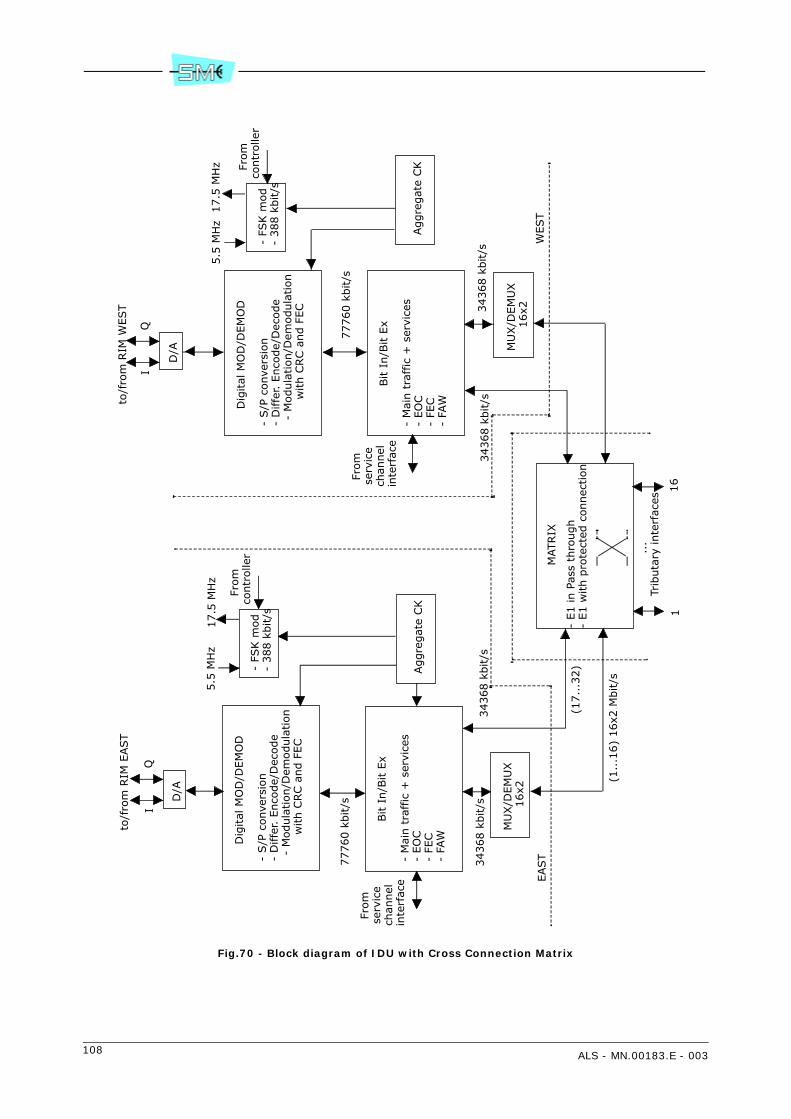
108 ALS - MN.00183.E - 003
Fig.70 - Block diagram of IDU with Cross Connection Matrix
D/A
Dig
ital
MO
D/D
EM
OD
- S/P
conve
rsio
n-
Diffe
r. E
nco
de/
Dec
ode
- M
odula
tion/D
emodula
tion
with C
RC a
nd F
EC
- FS
K m
od
- 388 k
bit/s
Bit I
n/B
it E
x
- M
ain t
raffic
+ s
ervi
ces
- EO
C-
FEC
- FA
W
Aggre
gat
e CK
MU
X/D
EM
UX
16x2
D/A
Dig
ital
MO
D/D
EM
OD
- S/P
conve
rsio
n-
Diffe
r. E
nco
de/
Dec
ode
- M
odula
tion/D
emodula
tion
with C
RC a
nd F
EC
- FS
K m
od
- 388 k
bit/s
Bit I
n/B
it E
x
- M
ain t
raffic
+ s
ervi
ces
- EO
C-
FEC
- FA
W
Aggre
gat
e CK
MU
X/D
EM
UX
16x2
MATRIX
- E1 in P
ass
thro
ugh
- E1 w
ith p
rote
cted
connec
tion
to/f
rom
RIM
EAST
QI
77760 k
bit/s
From
se
rvic
e ch
annel
in
terf
ace
34368 k
bit/s
EAST
34368 k
bit/s
(17..
.32)
(1..
.16)
16x2
Mbit/s
From
co
ntr
olle
r
17.5
MH
z5.5
MH
z
...
Trib
uta
ry inte
rfac
es
116
QI
From
se
rvic
e ch
annel
in
terf
ace
17.5
MH
z5.5
MH
z
From
co
ntr
olle
r
77760 k
bit/s
34368 k
bit/s
WEST
34368 k
bit/s
to/f
rom
RIM
WEST

ALS - MN.00183.E - 003 109
14.4.3 RIM
Refer to Fig.71.
The RIM consists of the following main circuits:
• IF part of the QAM modulator
• IF part of the QAM demodulator
• power supply
• telemetry IDU/ODU
14.4.3.1 QAM modulator
I and Q signals from LIM are connected to a 4 or 16QAM programmable modulator. It consists of the fol-lowing circuits:
• recovery low pass filter to eliminate signal periodicity
• two mixers for carrier amplitude and phase modulation process
• 330 MHz local oscillator
• a 90° phase shifter to supply two mixers with two in quadrature carriers
• a combiner circuit to generate the QAM modulation
The thus obtained 330 MHz QAM modulated carrier is then sent to the cable interface for connection withODU.
14.4.3.2 QAM demodulator
At the receive side, from the cable interface, the 140 MHz QAM modulated carrier is sent to the QAM de-modulator passing through a cable equalizer circuit. The QAM demodulator within the RIM extracts the Iand Q signals to be sent to the digital part of the demodulator within the LIM.
14.4.3.3 Power supply
The –48 V battery voltage feeds the IDU and ODU circuitry. The service voltages for the IDU feeding areachieved through a DC/DC converter for +3.6 V generation and a step down circuit for –5V.
Both voltages are protected against overvoltages and overcurrents.
The power to the ODU is given by the same battery running through the interconnection cable. An elec-tronic breaker protects the battery against cable failure.
14.4.3.4 Telemetry IDU/ODU
The dialogue IDU/ODU is made–up by the main controller and associated peripherals within the ODU. Con-trols for ODU management and alarm reporting is performed making use of a bidirectional 388 kbit/sframed signals. The transport along the interconnecting cable is carried out via two FSK modulated carri-ers: 17.5 MHz from IDU to ODU; 5.5 MHz from ODU to IDU.

110 ALS - MN.00183.E - 003
14.4.4 CONTROLLER
The controller module performs the following:
• interfaces the service signals
• houses the equipment software for equipment management
• interfaces the SCT/LCT program through supervision ports
• receive external alarms and route them to relay contacts along with the internal alarms generatedby the equipment.
Warning: lithium battery inside, refer to national rules for disposal.
14.4.4.1 Service signals
The controller offers an electrical interface to the following three service channel options:
• 9600 baud/V28 with digital party line or in alternative 2x4800 baud/V28 – 9600 baud V28/RS232synchronous/asynchronous channels
• 64 kbit/s/V11 codirectional or contradirectional
• 2 Mbit/s wayside G.703.
The service channels thus interfaced are then sent to the LIM for MUX/DEMUX processing.
14.4.4.2 Equipment software
Equipment software permits to control and manage all the equipment functionality. It is distributed on twohardware levels: main controller and ODU peripheral controllers.
The dialogue between main and peripheral controllers is shown in Fig.72.
Main controller
The activities executed by the main controller are the following:
• Communication management: it makes use of SNMP as management protocol and IP or IP over OSIas communication protocol stacks. See Fig.73 for details. The interface ports for the equipmentmanagement are the following:
- LAN Ethernet 10BaseT/10Base2 or AUI
- USB asynchronous used for SCT/LCT connection
- RS232 asynchronous used for connection to further NEs or for SCT/LCT connection
- EOC embedded within the PDH radio frame for connection to the remote NEs
- EOC embedded within the 2 Mbit/s tributary G.704 frame.
• Log–in: the main controller manages the equipment or network login/logout by setting and thencontrolling the user’s ID and relevant password.
• Database (MIB): validation and storing in a non–volatile memory of the equipment configurationparameters.
• Equipment configuration: distribution of the parameters stored in the MIB towards the peripheralµPs for their actuation in addition to the controls from user not stored in the MIB (i.e. loops, manualforcing etc...).
• Alarm monitoring: acquisition, filtering and correlation of the alarms gathered from slaved µPs. Lo-cal logger and alarm sending to the connected managers: SCT/LCT – NMS5UX. Management of thealarm signalling on the LIM front panel.
• Performances: PM management as per Recc. G.828.
ALS - MN.00183.E - 003 111
• Download: the main controller is equipped with two flash memory banks containing the running pro-gram (active bank) and the stand–by program (inactive bank). This permits to download a new soft-ware release to the inactive bank without distributing the traffic.Bank switch enables the new release to be used.Download activity is based on FTP protocol which downloads application programs, FPGA configu-ration, configuration files on main controller inactive bank or directly on the peripheral controllers.
Peripheral controllers
The peripheral controllers take place within the ODU and are slaved to main controller with the task of ac-tivating controls and alarm reporting of dedicated functionality.
14.4.4.3 Supervision ports
The equipment management is made by SCT/LCT program through the supervision ports.
The following are made available:
• LCT/RS232 interface ports using PPP protocol and baud rate speed up to 57600
• LAN interface using IP or IPoverOSI protocols
• EOC (Embedded Overhead Channel) using a 64 kbit/s slot of the radio frame to broadcast the su-pervision messages towards the remote terminals. The protocol used is IP or IPoverOSI.
14.5 IDU LOOPS
To control the IDU correct operation a set of local and remote loops are made available. The commandsare forwarded by the LCT/SCT program. Loop block diagram is shown by Fig.74.
14.5.1 Tributary loop
Tributary local loop
Each input tributary is routed directly to the trib. output upon receiving the command from the LCT. TheTx line transmission is still on.
Tributary remote loop
Each tributary directed towards the Rx output line is routed back to the Tx line. The Rx line is still on.
14.5.2 Baseband unit loop
This kind of loop is only local and is activated at BI/BE level. The Tx line is still on.

112 ALS - MN.00183.E - 003
14.5.3 IDU loop
This kind of loop permits to check the full IDU operation. When activated, the modulator output is connect-ed to demodulator input. The loop is assured by converting the frequency of the modulator from 330 MHzto 140 MHz.
East side or West side tributary loop
Tributaries, accessing the matrix from East side or West side, not assigned nor in a Transit nor in a crossconnection, can be looped back towards their direction of origin.
Fig.71 - RIM block diagram
Cab
le
inte
rfac
e
Ove
rcurr
ent
pro
tect
.
Rem
ote
pow
er s
upply
5.5
MH
z
QAM
MO
D(I
F par
t)
330 M
Hz
DC
DC
from
LIM
I&Q
bat
tery
-4
8 V
I/V
pro
tect
Ste
p
dow
n
+3.6
V
-5 V
Cab
le
equal
iz.
DEM
QAM
(IF
par
t)
I&Q
to L
IM
17.5
MH
zfr
om
LIM
to L
IM

ALS - MN.00183.E - 003 113
Fig.72 - Main and peripheral controller connection
Mai
n c
ontr
olle
r
338 k
b/s
388 k
bit/s
LAN
RS232
LCT
Use
r In
Ala
rm/
Use
r O
ut
FSK
modem
FSK
modem
OD
U2
388 k
b/s
388 k
bit/s
FSK
modem
FSK
modem O
DU
1
EO
C
388 k
bit/s
gen
erat
or
rece
iver
388 k
bit/s
gen
erat
or
rece
iver
gen
/rec
.Pe
ripher
alco
ntr
olle
rPe
ripher
alco
ntr
olle
rgen
/rec
.
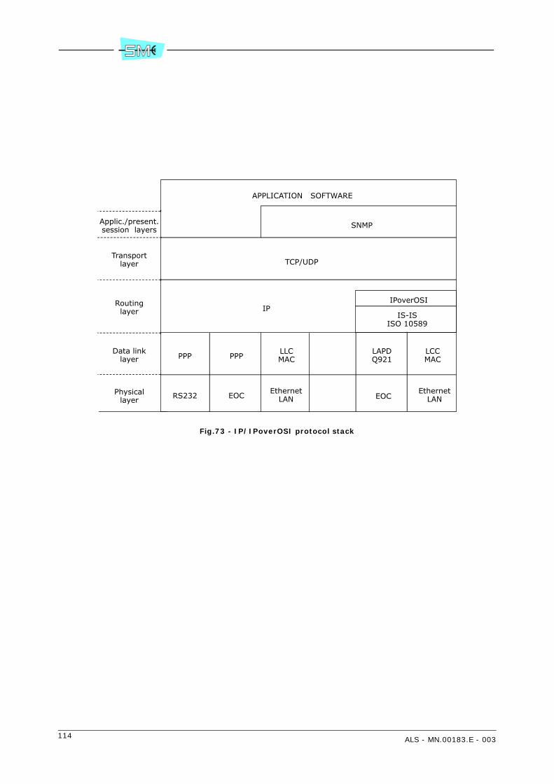
114 ALS - MN.00183.E - 003
Fig.73 - IP/IPoverOSI protocol stack
APPLICATION SOFTWARE
SNMP
TCP/UDP
IPIPoverOSI
IS-ISISO 10589
PPP PPPLLCMAC
LAPDQ921
LCCMAC
RS232 EOCEthernet
LAN EOCEthernet
LAN
Applic./present.session layers
Transportlayer
Routinglayer
Data linklayer
Physicallayer
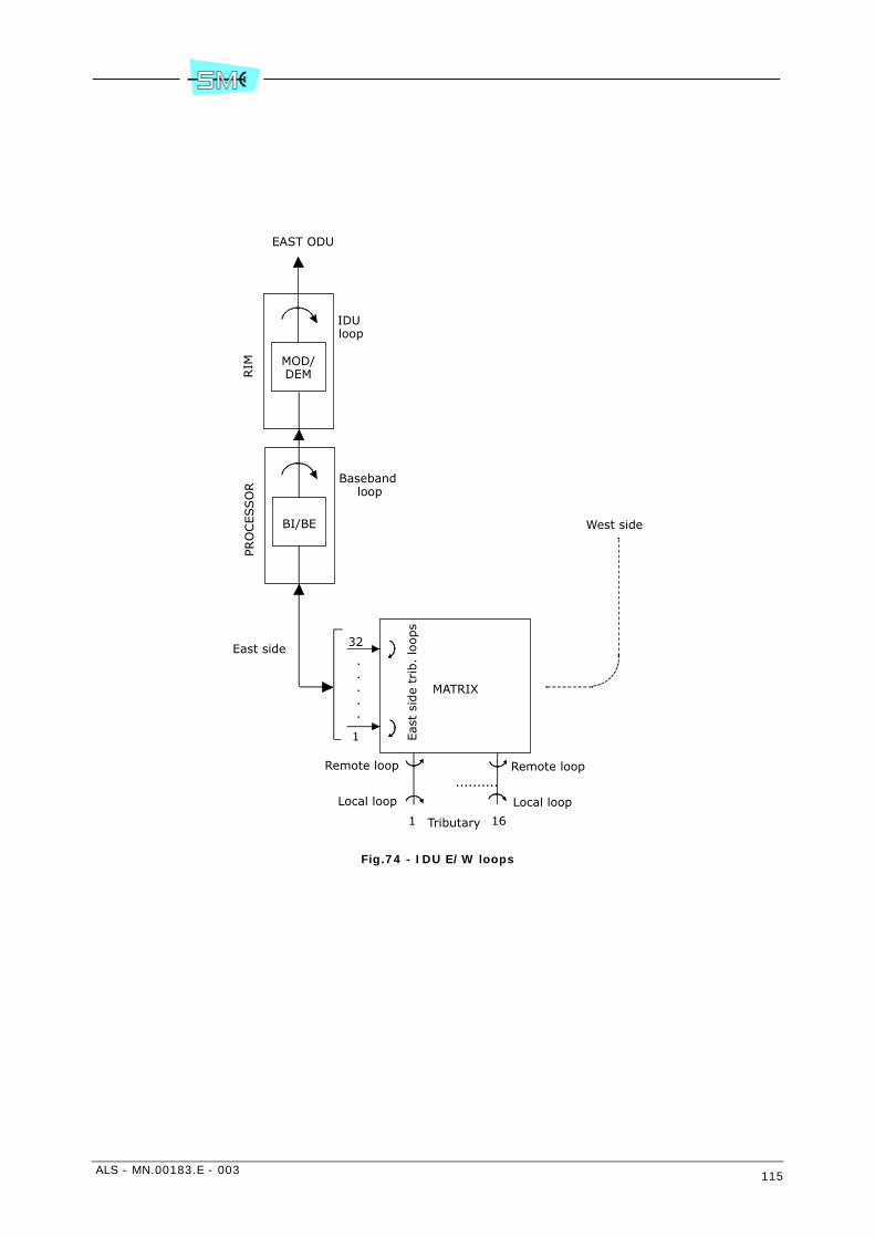
ALS - MN.00183.E - 003 115
Fig.74 - IDU E/W loops
MATRIX
32
.
.
.
.
.
1
1 16
BI/BE
MOD/DEM
PRO
CESSO
RRIM
East side
Remote loop
Local loop
Remote loop
Local loop
..........
EAST ODU
West side
IDU loop
Baseband loop
Tributary
Eas
t si
de
trib
. lo
ops

116 ALS - MN.00183.E - 003
15 CHARACTERISTICS OF THE OUTDOOR UNIT
15.1 GENERAL
The ODU unit is available in two different versions: AL and AS.AS ODU is also called Universal ODU because it can work with ALS equipment (SDH).The following ODU characteristics are guaranteed for the temperature range from –33° C to +55° C.
15.2 TECHNICAL SPECIFICATION
- Output power at the antenna side see Tab.17
- Tuning range
- AL4 45.5 MHz
- AL7 42 MHz (154 MHz go-return)56 MHz (161/168/196 MHz go-return)94 MHz (245 MHz go-return)
- AL8 42 MHz (119 and 126 MHz go-return)112 MHz (310 MHz go-return)120 MHz (311,32 MHz go-return)91 MHz (266 MHz go-return)94.5 MHz (274 MHz go-return)
- AL13 84 MHz
- AL15 84 MHz (315/322 MHz go-return119 MHz (420/490/728 MHz go-return)
- AL18 330 MHz
- AL23 336 MHz
- AL25/AL28 448 MHz
- AL32 252/280 MHz
- AL38 560 MHz
- RF frequency agility 125 kHz step
- Duplex spacing
- AL4 100 MHz
- AL7 154/161/168/196/245 MHz
- AL8 311,32 MHz
- AL11 490/530 MHz
- AL13 266 MHz
- AL15 315/322/420/490/728 MHz
- AL18 1010 MHz
- AL23 1008/1232 MHz
- AL25 1008 MHz
- AL28 1008 MHz
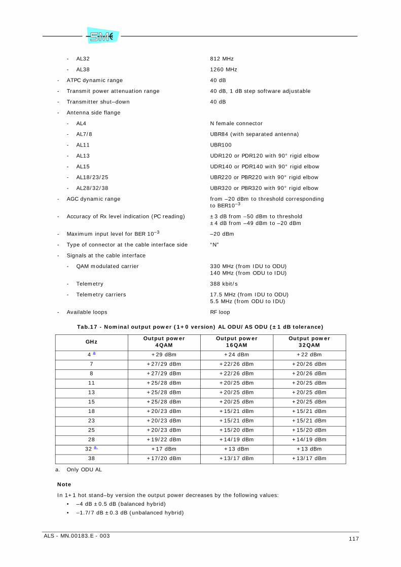
ALS - MN.00183.E - 003 117
- AL32 812 MHz
- AL38 1260 MHz
- ATPC dynamic range 40 dB
- Transmit power attenuation range 40 dB, 1 dB step software adjustable
- Transmitter shut–down 40 dB
- Antenna side flange
- AL4 N female connector
- AL7/8 UBR84 (with separated antenna)
- AL11 UBR100
- AL13 UDR120 or PDR120 with 90° rigid elbow
- AL15 UDR140 or PDR140 with 90° rigid elbow
- AL18/23/25 UBR220 or PBR220 with 90° rigid elbow
- AL28/32/38 UBR320 or PBR320 with 90° rigid elbow
- AGC dynamic range from –20 dBm to threshold corresponding to BER10–3
- Accuracy of Rx level indication (PC reading) ±3 dB from –50 dBm to threshold±4 dB from –49 dBm to –20 dBm
- Maximum input level for BER 10–3 –20 dBm
- Type of connector at the cable interface side “N”
- Signals at the cable interface
- QAM modulated carrier 330 MHz (from IDU to ODU)140 MHz (from ODU to IDU)
- Telemetry 388 kbit/s
- Telemetry carriers 17.5 MHz (from IDU to ODU)5.5 MHz (from ODU to IDU)
- Available loops RF loop
Tab.17 - Nominal output power (1+0 version) AL ODU/AS ODU (±1 dB tolerance)
Note
In 1+1 hot stand–by version the output power decreases by the following values:
• –4 dB ±0.5 dB (balanced hybrid)
• –1.7/7 dB ±0.3 dB (unbalanced hybrid)
GHzOutput power
4QAMOutput power
16QAMOutput power
32QAM
4 a
a. Only ODU AL
+29 dBm +24 dBm +22 dBm
7 +27/29 dBm +22/26 dBm +20/26 dBm
8 +27/29 dBm +22/26 dBm +20/26 dBm
11 +25/28 dBm +20/25 dBm +20/25 dBm
13 +25/28 dBm +20/25 dBm +20/25 dBm
15 +25/28 dBm +20/25 dBm +20/25 dBm
18 +20/23 dBm +15/21 dBm +15/21 dBm
23 +20/23 dBm +15/21 dBm +15/21 dBm
25 +20/23 dBm +15/20 dBm +15/20 dBm
28 +19/22 dBm +14/19 dBm +14/19 dBm
32 a. +17 dBm +13 dBm +13 dBm
38 +17/20 dBm +13/17 dBm +13/17 dBm

118 ALS - MN.00183.E - 003
16 OUTDOOR UNIT DESCRIPTION
16.1 GENERAL
The 1+0 ODU (refer to Fig.75 or to Fig.77) consists of a two shell aluminium mechanical structure, oneshell housing all the ODU circuits, the other forming the covering plate.
On the ODU are accessible:
• the “N” type connector for cable interfacing IDU and ODU
• the “BNC” connector for connection to a multimeter with the purpose to measure the received fieldstrength
• a ground bolt.
The 1+1 hot stand–by version (refer to Fig.76) consist of two 1+0 ODUs mechanically secured to a struc-ture housing the hybrid for the antenna connection.
ODU exists in two different versions, AL and AS. They differs about dimensions and output power.
AS ODU is also called Universal because it can work with ALS equipment (SDH).
16.2 TRANSMIT SECTION
Refer to block diagram shown in Fig.78.
The 330 MHz QAM modulated carrier from the cable interface (see chapter 16.4 CABLE INTERFACE) is for-warded to a mixer passing through a cable equalizer for cable loss compensation up to 40 dB at 330 MHz.The mixer and the following bandpass filter give rise to a second IF Tx carrier the frequency of which de-pends on the go/return frequency value. The mixer is of SHP type.
The IF Tx frequency is µP controlled. Same happens to Rx IF and RF local oscillators. This latter is commonto both Tx and Rx sides.
The IF carrier is converted to RF and then amplified making use of a MMIC circuit. The conversion mixer isSSB type with side band selection.
The power at the MMIC output can be manually attenuated by 40 dB, 1 dB step.
Total attenuation is 40 dB including the 20 dB attenuator that follows.
The automatic adjustment is performed making use of an ATPC (see paragraph 16.5 ATPC OPERATION fordetails). The regulated output power is kept constant against amplifier stage gain variation by a feedbackincluding the AGC.
Before reaching the antenna side the RF signal at the output of MMIC passes through the following circuits:
• a decoupler plus detector diode to measure the output power
• a circulator to protect the amplifier stages against possible circuit mismatch.
• a ON/OFF switch for 1+1 operation
• an RF bandpass filter for antenna coupling.
An RF coupler plus a detector and a shift oscillator made up the RF loop which is enabled upon receiving aµP control. The RF loop permits the Tx power to return back to receive side thus controlling the total localradio terminal performance.
ALS - MN.00183.E - 003 119
16.3 RECEIVE SECTION
The RF signal from the Rx bandpass filter is sent to a low noise amplifier that improves the receiver sen-sitivity. The following down–converter translates the RF frequency to approximately 765 MHz. The conver-sion mixer is SSB type. The sideband selection is given through a µP control.
A second down converter generates the 140 MHz IF carrier to be sent to the demodulator within the IDU.The level of the IF carrier is kept constant to –5 dBm thank to the IF amplifier stages, AGC controlled,distributed in the IF chain. In addition the AGC gives a measure of the receive RF level.
Between two amplifiers a bandpass filter assures the required selectivity to the receiver. The filter is SAWtype and the bandwidth depends on the transmitted capacity.
16.4 CABLE INTERFACE
The cable interface permits to interface the cable interconnecting IDU to ODU and viceversa.
It receives/transmits the following signals:
• 330 MHz (from IDU to ODU)
• 140 MHz (from ODU to IDU)
• 17.5 MHz (from IDU to ODU)
• 5.5 MHz (from ODU to IDU)
• remote power supply.
The 17.5 MHz and 5.5 MHz FSK modulated carriers, carry the telemetry channel. This latter consists of two388 kbit/s streams one from IDU to ODU with the information to manage the ODU (RF power, RF frequen-cy, capacity, etc...) while the other, from ODU to IDU, sends back to IDU measurements and alarms of theODU. The ODU management is made by a µP.
16.5 ATPC OPERATION
The ATPC regulates the RF output power of the local transmitter depending on the value of the RF level atthe remote terminal. This value has to be preset from the local terminal as threshold high and low. Thedifference between the two thresholds must be equal or higher than 3 dB.
As soon as the received level crosses the preset threshold level low (see Fig.81) due to the increase of thehop attenuation, a microP at the received side of the remote terminal sends back to the local terminal acontrol to increase the transmitted power. The maximum ATPC range is 40 dB.
If the hop attenuation decreases and the threshold high is crossed then the control sent by the microPcauses the output power to decrease.
16.6 1+1 Tx SYSTEM
The two ODUs are coupled to the antenna side via a balanced or unbalanced hybrid.
1+1 Tx switching occurs in the 1+1 hot stand–by 1 antenna or 2 antennas versions as shown in Fig.79 andFig.80.
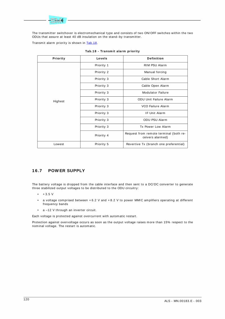
120 ALS - MN.00183.E - 003
The transmitter switchover is electromechanical type and consists of two ON/OFF switches within the twoODUs that assure at least 40 dB insulation on the stand–by transmitter.
Transmit alarm priority is shown in Tab.18.
Tab.18 - Transmit alarm priority
16.7 POWER SUPPLY
The battery voltage is dropped from the cable interface and then sent to a DC/DC converter to generatethree stabilized output voltages to be distributed to the ODU circuitry:
• +3.5 V
• a voltage comprised between +6.2 V and +8.2 V to power MMIC amplifiers operating at differentfrequency bands
• a –12 V through an inverter circuit.
Each voltage is protected against overcurrent with automatic restart.
Protection against overvoltage occurs as soon as the output voltage raises more than 15% respect to thenominal voltage. The restart is automatic.
Priority Levels Definition
Highest
Priority 1 RIM PSU Alarm
Priority 2 Manual forcing
Priority 3 Cable Short Alarm
Priority 3 Cable Open Alarm
Priority 3 Modulator Failure
Priority 3 ODU Unit Failure Alarm
Priority 3 VCO Failure Alarm
Priority 3 IF Unit Alarm
Priority 3 ODU PSU Alarm
Priority 3 Tx Power Low Alarm
Priority 4Request from remote terminal (both re-
ceivers alarmed)
Lowest Priority 5 Revertive Tx (branch one preferential)
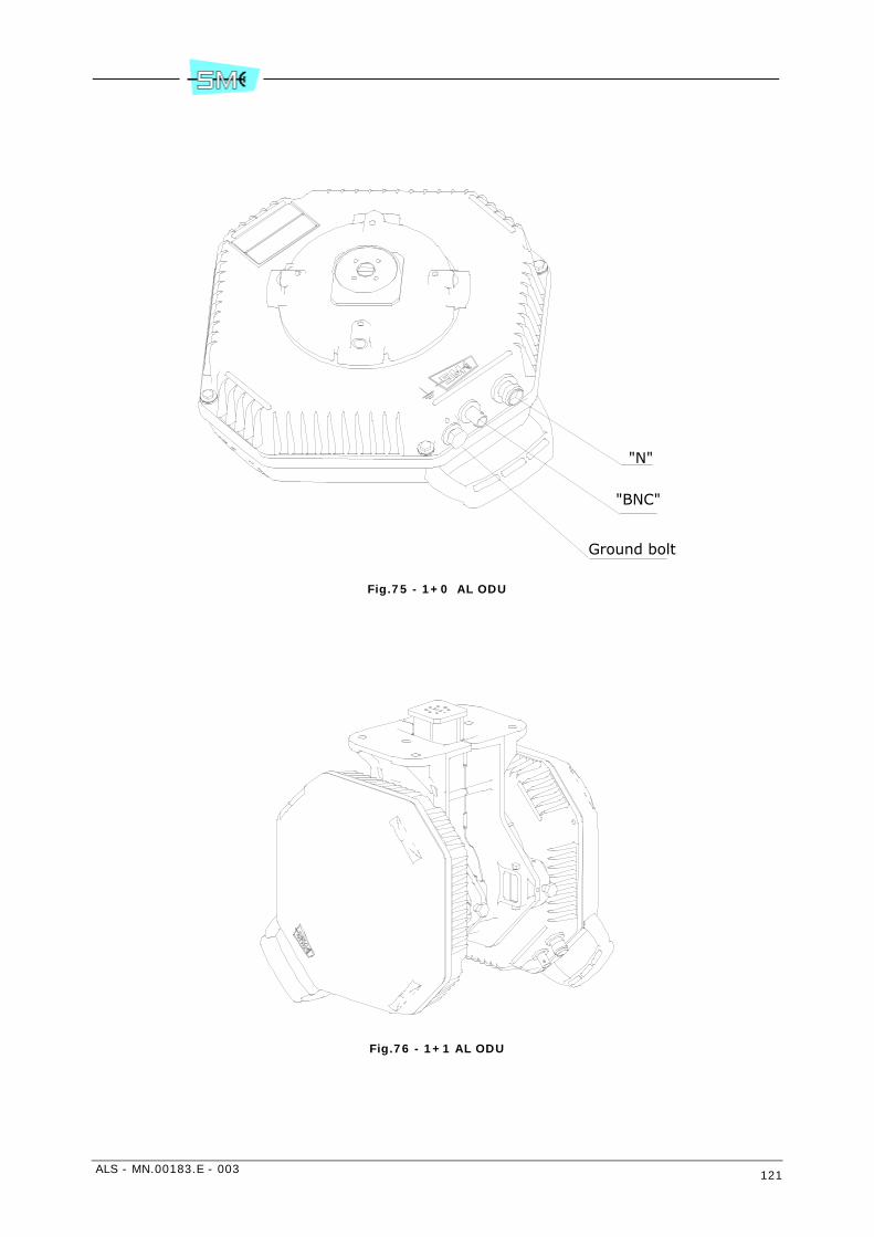
ALS - MN.00183.E - 003 121
Fig.75 - 1+0 AL ODU
Fig.76 - 1+1 AL ODU
"N"
"BNC"
Ground bolt
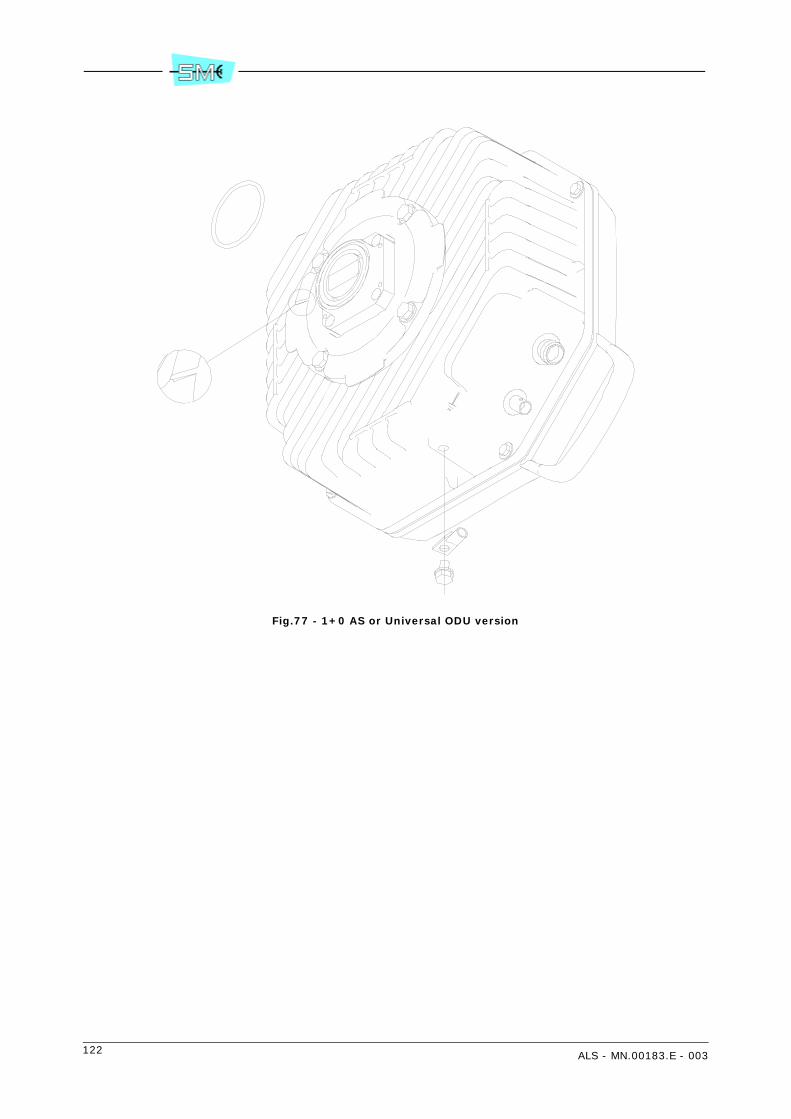
122 ALS - MN.00183.E - 003
Fig.77 - 1+0 AS or Universal ODU version
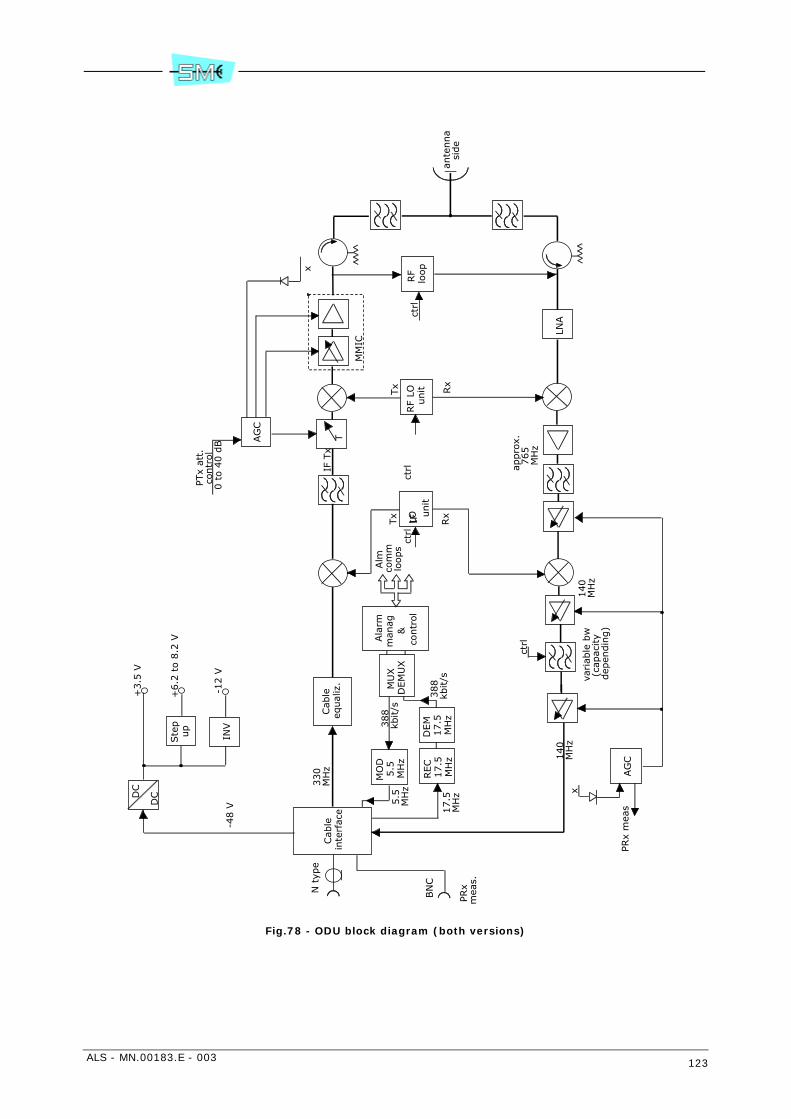
ALS - MN.00183.E - 003 123
Fig.78 - ODU block diagram (both versions)
Cab
lein
terf
ace
Cab
leeq
ual
iz.
DC
DC
Ste
p
up
T
LNA
MM
IC
variab
le b
w
(cap
acity
dep
endin
g)
AG
C
N t
ype
330
MH
z
-48 V
x
PRx
mea
s
140
MH
z140
MH
z
appro
x.765
MH
z
+3.5
V
+6.2
to 8
.2 V
-12 V
AG
C
x
PTx
att.
co
ntr
ol
0 t
o 4
0 d
B
IF
LO
unit
MO
D
5.5
M
Hz
REC
17.5
M
Hz
DEM
17.5
M
Hz
MU
X
DEM
UX
388
kbit/s
Ala
rmm
anag
&
co
ntr
ol
Alm
com
mlo
ops
5.5
M
Hz
17.5
M
Hz
388
kbit/s
IF T
x
ante
nna
side
INV
BN
C
PRx
mea
s.
ctrl
RF
LO
unit Rx
Tx
RF
loop
ctrl
ctrl
ctrl
Rx
Tx

124 ALS - MN.00183.E - 003
Fig.79 - 1+1 hot stand–by 1 antenna
Fig.80 - 1+1 hot stand–by 2 antennas
Antenna side
SW control
Tx side
Rx side
SW control
Tx side
Rx side
First antenna
SW control
Tx side
Rx side
SW control
Tx side
Rx side
Second antenna
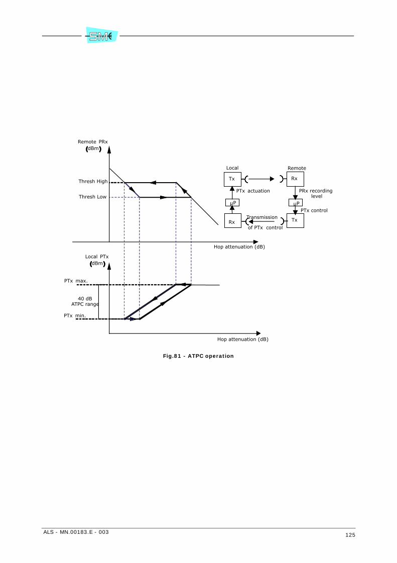
ALS - MN.00183.E - 003 125
Fig.81 - ATPC operation
Thresh High
Thresh Low
Hop attenuation (dB)
40 dBATPC range
PTx max.
PTx min.
Remote PRxdBm
Local PTxdBm
Hop attenuation (dB)
Tx
Rx
Rx
Tx
PTx actuation
Local Remote
PRx recording
Transmission
of PTx control
µP µPlevel
PTx control

126 ALS - MN.00183.E - 003
17 24/48 VOLT DC/DC CONVERTER D52089
17.1 GENERAL
The 24/48V DC/DC converter D52089 is a unit which converts the voltage of 24 Vdc in –48 Vdc.
This unit is housed in a subrack 1 RU unit G52004 with two D52089 units (1+1 version). For 1+0 versionthe subrack is G52003 with one D52089 unit and the remaining half front panel has a cover.
These subracks have a free air gap for cooling purpose.
The DC/DC converter unit D52089 is shown in Fig.82.
Fig.82 - DC/DC converter front coverplate
17.2 ENVIRONMENTAL CONDITIONS
- Operational range -10° ÷ 50° C
- Storage range -40° ÷ 80° C
- Operational humidity 90% max in the range -5° ÷ 30° C
17.3 ELECTRICAL CHARACTERISTICS
- Vinput 24 Vdc (20.4 ÷ 28.8 Vdc floating)
- Voutput 52 Vdc
- Max current in input 4.5 A
- Max 24 Vdc consumption 90 W
- Max 48 Vdc load 75 W
- Secondary voltage ripple ≤ 200 mVpp
- Surge current (Inrush current) ETS 300 132-2
- Conducted immunity ETS 300 132-2
+ – – +
6,3A250V
M ON 24VdcIN
48VdcOUT2A
ALARM
Green LED CM2 connector
Fuse 6.3 A 24 Vdc input male 3W3 connector
48 Vdc output female 3W3 connector

ALS - MN.00183.E - 003 127
- Conducted emission ETS 300 132-2
- Short duration voltage transient ETS 300 132-2 (ETR 283)
- Abnormal service voltage ETS 300 132-2
- Voltage changes due to the regulation of power supply ETS 300 132-2
- Electromagnetic compatibility EN 300 086
- Safety EN 60950-1
- Protections against - input polarity inversion (fuse) - surge input current (fuse) - continuous short circuit at output with automatic recovery
- Visual indication ON = green led active on input primary voltagepresent
- Alarm (CM2 connector) with relay contact on 9 pin male SUB–D connector Alarm off: 8–9 pin open, 7–9 pin closed Alarm on when Vout decreases ≥ 15%: 8–9 pinclosed, 7–9 pin open
- Fuse 6.3 A medium time 250 Volt
Fig.83 shows, as example, connection from IDU 1+0 AL compact version to 24/48 V converter with cableF03489.
Fig.84 shows, as example, connections from IDU 1+1 AL compact version to 24/48 V converter with cablesF03489 and F03278.
Warning: connect only 24 Vdc to primary input 24 Vdc IN.
Warning: power supply from –48 Vdc must be connected directly to ALC IDU.

128 ALS - MN.00183.E - 003
Fig.83 - 24/48 V DC/DC converter connections to IDU 1+0
V052MA 3, 6
NO
NIcd
V 42A2T
UO
c dV8 4
MR
ALA
+
––
+
98430F
A 3.6 esuFNI cdV 42
V84
+
–
4–3–2–1 .b irT
8–7–6–5 .birT
SP
TCL
TU
O/NI
RESU
3Q
R
TS
ET
LA
3002 5G : gninra
WNI cdV 42 tupni yra
mirp ot cdV 42 ylno tcennoc

ALS - MN.00183.E - 003 129
Fig.84 - 24/48 V DC/DC converter connections to IDU 1+1
V05 2M
A3 ,6 N
ONI
cdV4 2
A 2T
UO
cdV 84
MR
ALA
MV052
A3,6 N
ONI
cdV42
A2T
UO
cdV8 4
MR
ALA
+
––
+
+
––
+
21
XR
XT
LAT
SET R
TU
O/N I
RESU
3Q
TCL
2S
P
1S
P
61 –51– 41–3 1 .b irT8–7– 6–5 .bir T
1–01–9 .birT21–1
4 –3–2– 1 .b irT
21
21
2V84
+
––
+
1V84
98430F87230F
NI cdV 42
NI cdV 42
esuFA 3.6
A 3.6 esuF
:g nin raW
NI c dV 42 tu pni y rami rp ot c dV 42 y lno t ce nnoc

130 ALS - MN.00183.E - 003

ALS - MN.00183.E - 003 131
Section 3.INSTALLATION
18 INSTALLATION AND PROCEDURES FOR ENSUR-ING THE ELECTROMAGNETIC COMPATIBILITY
18.1 GENERAL INFORMATION TO BE READ BEFORE THE INSTALLA-TION
ALS equipment is a split mount (indoor-outdoor) PDH/SDH radio link system operating in the frequencyranges 4, 6, 7, 8, 13, 15, 18, 23, 25, 28 and 38 GHz, for low, medium and high transport capacity (from4 up to 622 Mbit/s), designed to establish LAN-LAN connections and PDH/SDH access. For the details re-lated to the actual used frequency band refer to the label on the equipment.
The system is provided with an integral antenna; however, in case its antenna is not used, it should beconnected to an antenna conforming to the requirements of ETSI EN 302 217-4-2 for the relevant frequen-cy band.
The equipment is composed by the following separate units:
• radio unit (outdoor) with or without integral antenna
• Baseband (indoor)
This equipment makes use of non-harmonized frequency bands.
Class 2 radio equipment subject to Authorisation of use. The equipment can operate only at the fre-quencies authorised by the relevant National Authority.
The deployment and use of this equipment shall be made in agreement with the national regulationfor the Protection from Exposure to Electromagnetic Field.
The symbol indicates that, within the European Union, the product is subject to separate collec-tion at the product end-of-life. Do not dispose of these products as unsorted municipal waste. For moreinformation, please contact the relevant supplier for verifying the procedure of correct disposal.
132 ALS - MN.00183.E - 003
18.2 GENERAL
The equipment consists of IDU and ODU(s) units and is mechanically made up of a wired 19” subrack (IDU)and a weather proof metallic container (ODU). The two units are shipped together in an appropriate card-board box.
After unpacking, mechanical installation takes place followed by electrical connections as described in thefollowing paragraphs.
18.3 MECHANICAL INSTALLATION
18.3.1 IDU installation
On their sides the subracks making up the several IDU versions are provided with two holes for the M6screws fastening the subracks to a rack or to a 19” mechanical structure. The front of the IDU mechanicalstructure is provided with the holes at the sides. This permits to fasten the subrack to a 19” rack by meansof 4 M6 screws.
18.3.2 1RU IDU installation
To avoid overtemperature problems the free space below and above a 1RU IDU must be 44 mm (1RU)minimum.
18.3.3 2RU IDU installation
To avoid overtemperature problems the free space below and above a 2RU IDU must be 44 mm (1RU)minimum.
Nodal and Drop/Insert compositions need the use of D12148-03 controller. In case of different com-positions it is necessary to have 88 mm (2RU) free space below and above the 2RU IDU.
18.4 ELECTRICAL WIRING
The electrical wiring must be done using appropriate cables thus assuring the equipment responds to theelectromagnetic compatibility standards.
The cable terminates to flying connectors which have to be connected to the corresponding connectors onthe equipment front.
Position and pin–out of the equipment connectors are available in this section.
Tab.19 shows the characteristics of the cables to be used and the flying connector types.
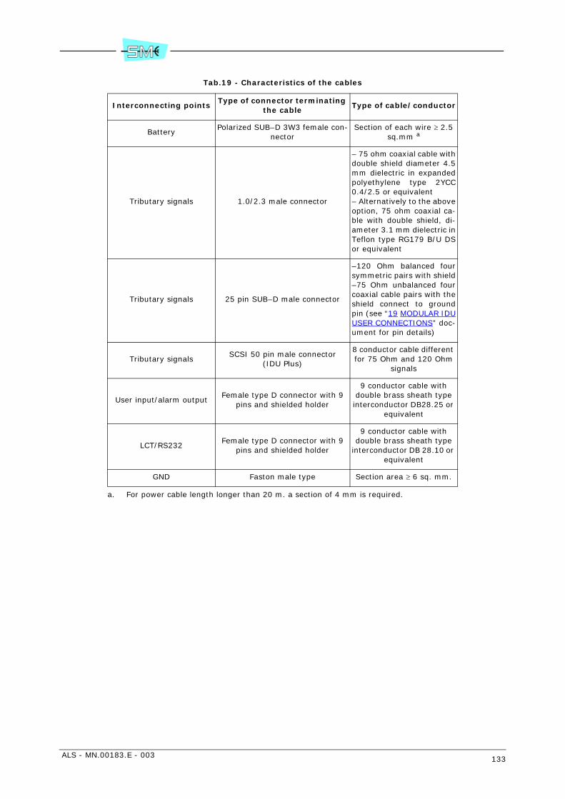
ALS - MN.00183.E - 003 133
Tab.19 - Characteristics of the cables
Interconnecting pointsType of connector terminating
the cableType of cable/conductor
BatteryPolarized SUB–D 3W3 female con-
nectorSection of each wire ≥ 2.5
sq.mm a
a. For power cable length longer than 20 m. a section of 4 mm is required.
Tributary signals 1.0/2.3 male connector
– 75 ohm coaxial cable withdouble shield diameter 4.5mm dielectric in expandedpolyethylene type 2YCC0.4/2.5 or equivalent– Alternatively to the aboveoption, 75 ohm coaxial ca-ble with double shield, di-ameter 3.1 mm dielectric inTeflon type RG179 B/U DSor equivalent
Tributary signals 25 pin SUB–D male connector
–120 Ohm balanced foursymmetric pairs with shield–75 Ohm unbalanced fourcoaxial cable pairs with theshield connect to groundpin (see “19 MODULAR IDUUSER CONNECTIONS” doc-ument for pin details)
Tributary signalsSCSI 50 pin male connector
(IDU Plus)
8 conductor cable different for 75 Ohm and 120 Ohm
signals
User input/alarm outputFemale type D connector with 9
pins and shielded holder
9 conductor cable with double brass sheath type
interconductor DB28.25 or equivalent
LCT/RS232 Female type D connector with 9
pins and shielded holder
9 conductor cable with double brass sheath type
interconductor DB 28.10 or equivalent
GND Faston male type Section area ≥ 6 sq. mm.

134 ALS - MN.00183.E - 003
18.5 CONNECTIONS TO THE SUPPLY MAINS
During the final installation, the IDU must be protected by a magneto-thermal switch (not supplied withthe equipment), whose characteristics must comply with the laws in force in one's country.
The disconnection from the supply mains is made disconnecting the connector SUB-D 3W3 from the IDU.
18.6 GROUNDING CONNECTION
Fig.85 and annexed legend show how to perform the grounding connections.
Legend
1 IDU grounding point, faston type. The cross section area of the cable used must be ≥ 4 sq. mm. Thefaston is available on the IDU both sides.
2 ODU grounding bolt. The cross section area of the cable used must be ≥ 16 sq. mm
3 IDU–ODU interconnection cable type Celflex CUH 1/4” terminated with N–type male connectors atboth sides.
4 Grounding kit type Cabel Metal or similar to connect the shield of interconnection cable.
5 Matching cable (tail) terminated with SMA or BNT male and N female connectors.
6 Battery grounding point of IDU to be connected to earth by means of a cable with a section area2.5 sq. mm. Length ≤ 10 m.
7 Grounding cords connected to a real earth internal of station. The cross section area of the cablemust be ≥ 16 sq. mm
Fig.85 - Grounding connection
IDUunit
ODUunit
2
6(+) (-)
4
Localground
rackground
Indoor
Stationground
7
1 5
3 4 3
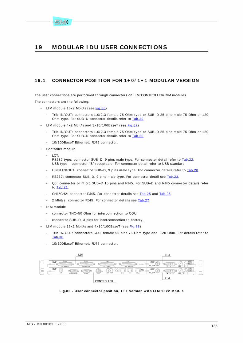
ALS - MN.00183.E - 003 135
19 MODULAR IDU USER CONNECTIONS
19.1 CONNECTOR POSITION FOR 1+0/1+1 MODULAR VERSION
The user connections are performed through connectors on LIM/CONTROLLER/RIM modules.
The connectors are the following:
• LIM module 16x2 Mbit/s (see Fig.86)
- Trib IN/OUT: connectors 1.0/2.3 female 75 Ohm type or SUB–D 25 pins male 75 Ohm or 120Ohm type. For SUB–D connector details refer to Tab.20.
• LIM module 4x2 Mbit/s and 3x10/100BaseT (see Fig.87)
- Trib IN/OUT: connectors 1.0/2.3 female 75 Ohm type or SUB–D 25 pins male 75 Ohm or 120Ohm type. For SUB–D connector details refer to Tab.20.
- 10/100BaseT Ethernet: RJ45 connector.
• Controller module
- LCT:RS232 type: connector SUB–D, 9 pins male type. For connector detail refer to Tab.22.USB type – connector “B” receptable. For connector detail refer to USB standard.
- USER IN/OUT: connector SUB–D, 9 pins male type. For connector details refer to Tab.28.
- RS232: connector SUB–D, 9 pins male type. For connector detail see Tab.23.
- Q3: connector or micro SUB–D 15 pins and RJ45. For SUB–D and RJ45 connector details referto Tab.21.
- CH1/CH2: connector RJ45. For connector details see Tab.25 and Tab.26.
- 2 Mbit/s: connector RJ45. For connector details see Tab.27.
• RIM module
- connector TNC–50 Ohm for interconnection to ODU
- connector SUB–D, 3 pins for interconnection to battery.
• LIM module 16x2 Mbit/s and 4x10/100BaseT (see Fig.88)
- Trib IN/OUT: connectors SCSI female 50 pins 75 Ohm type and 120 Ohm. For details refer toTab.36
- 10/100BaseT Ethernet: RJ45 connector.
Fig.86 - User connector position, 1+1 version with LIM 16x2 Mbit/s
RIM
RIM
1
2
2
1
RIM
RIM
-
++
-Trib: M-N-O-PTrib: I-J-K-LTrib: E-F-G-H
2Mb/s2Mb/s2Mb/s2Mb/s
Trib: A-B-C-D
FAIL
RIDU ODU
TESTREM
TX RX12 SIDE
2Mb/sCH2CH1Q3
RS232USER IN/OUT
A WAY
LCT
RIM
CONTROLLER
LIM
RIM
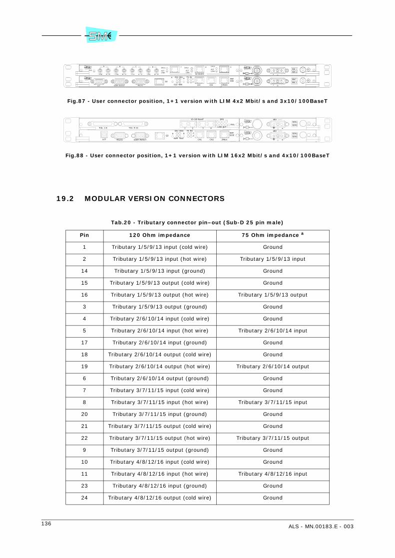
136 ALS - MN.00183.E - 003
Fig.87 - User connector position, 1+1 version with LIM 4x2 Mbit/s and 3x10/100BaseT
Fig.88 - User connector position, 1+1 version with LIM 16x2 Mbit/s and 4x10/100BaseT
19.2 MODULAR VERSION CONNECTORS
Tab.20 - Tributary connector pin–out (Sub-D 25 pin male)
Pin 120 Ohm impedance 75 Ohm impedance a
1 Tributary 1/5/9/13 input (cold wire) Ground
2 Tributary 1/5/9/13 input (hot wire) Tributary 1/5/9/13 input
14 Tributary 1/5/9/13 input (ground) Ground
15 Tributary 1/5/9/13 output (cold wire) Ground
16 Tributary 1/5/9/13 output (hot wire) Tributary 1/5/9/13 output
3 Tributary 1/5/9/13 output (ground) Ground
4 Tributary 2/6/10/14 input (cold wire) Ground
5 Tributary 2/6/10/14 input (hot wire) Tributary 2/6/10/14 input
17 Tributary 2/6/10/14 input (ground) Ground
18 Tributary 2/6/10/14 output (cold wire) Ground
19 Tributary 2/6/10/14 output (hot wire) Tributary 2/6/10/14 output
6 Tributary 2/6/10/14 output (ground) Ground
7 Tributary 3/7/11/15 input (cold wire) Ground
8 Tributary 3/7/11/15 input (hot wire) Tributary 3/7/11/15 input
20 Tributary 3/7/11/15 input (ground) Ground
21 Tributary 3/7/11/15 output (cold wire) Ground
22 Tributary 3/7/11/15 output (hot wire) Tributary 3/7/11/15 output
9 Tributary 3/7/11/15 output (ground) Ground
10 Tributary 4/8/12/16 input (cold wire) Ground
11 Tributary 4/8/12/16 input (hot wire) Tributary 4/8/12/16 input
23 Tributary 4/8/12/16 input (ground) Ground
24 Tributary 4/8/12/16 output (cold wire) Ground
RIDU ODU TX RX
12 SIDE
AWAY
DCBA
10/100 BTX
2
2
1
RIM
RIM
RIM
RIM12
USER IN/OUTLCT RS232
FAIL
DPLX
ACTLINK
DPLX
ACTLINK
DPLX
ACTLINK
1 3
Q3
TEST REM CH1 CH2 2 Mbit/s +
+
-
-
Q3WAYA
LCT USER IN/OUTRS232 CH1 CH2 2Mb/s
SIDE21
RXTX
REM TEST
ODUIDUR RIM
RIM
1
2
+ -
-+
2
1
RIM
RIM48V
48V
10-100 BaseT
4321LINK ACT
DPX
FAIL
Trib: 9-16Trib: 1-8
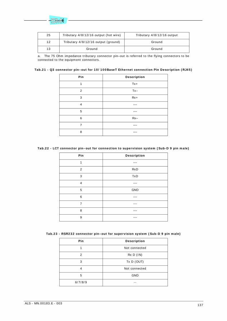
ALS - MN.00183.E - 003 137
Tab.21 - Q3 connector pin–out for 10/100BaseT Ethernet connection Pin Description (RJ45)
Tab.22 - LCT connector pin–out for connection to supervision system (Sub-D 9 pin male)
Tab.23 - RSR232 connector pin–out for supervision system (Sub-D 9 pin male)
25 Tributary 4/8/12/16 output (hot wire) Tributary 4/8/12/16 output
12 Tributary 4/8/12/16 output (ground) Ground
13 Ground Ground
a. The 75 Ohm impedance tributary connector pin–out is referred to the flying connectors to beconnected to the equipment connectors.
Pin Description
1 Tx+
2 Tx–
3 Rx+
4 ––
5 ––
6 Rx–
7 ––
8 ––
Pin Description
1 ––
2 RxD
3 TxD
4 ––
5 GND
6 ––
7 ––
8 ––
9 ––
Pin Description
1 Not connected
2 Rx D (IN)
3 Tx D (OUT)
4 Not connected
5 GND
6/7/8/9 --
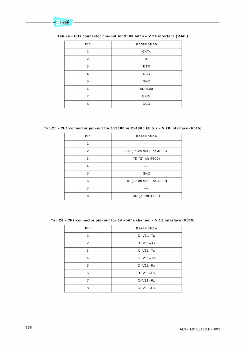
138 ALS - MN.00183.E - 003
Tab.24 - CH1 connector pin–out for 9600 bit/s – V.24 interface (RJ45)
Tab.25 - CH1 connector pin–out for 1x9600 or 2x4800 kbit/s – V.28 interface (RJ45)
Tab.26 - CH2 connector pin–out for 64 kbit/s channel – V.11 interface (RJ45)
Pin Description
1 CKTx
2 TD
3 DTR
4 DSR
5 GND
6 RD9600
7 CKRx
8 DCD
Pin Description
1 ––
2 TD (1° ch 9600 or 4800)
3 TD (2° ch 4800)
4 ––
5 GND
6 RD (1° ch 9600 or 4800)
7 ––
8 RD (2° ch 4800)
Pin Description
1 D–V11–Tx
2 D+V11–Tx
3 C–V11–Tx
4 C+V11–Tx
5 D–V11–Rx
6 D+V11–Rx
7 C–V11–Rx
8 C+V11–Rx
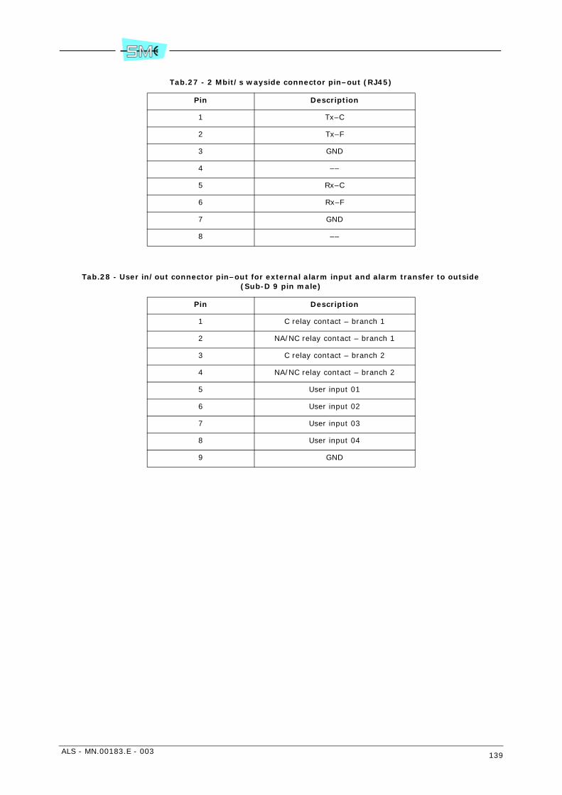
ALS - MN.00183.E - 003 139
Tab.27 - 2 Mbit/s wayside connector pin–out (RJ45)
Tab.28 - User in/out connector pin–out for external alarm input and alarm transfer to outside (Sub-D 9 pin male)
Pin Description
1 Tx–C
2 Tx–F
3 GND
4 ––
5 Rx–C
6 Rx–F
7 GND
8 ––
Pin Description
1 C relay contact – branch 1
2 NA/NC relay contact – branch 1
3 C relay contact – branch 2
4 NA/NC relay contact – branch 2
5 User input 01
6 User input 02
7 User input 03
8 User input 04
9 GND

140 ALS - MN.00183.E - 003
20 IDU COMPACT USER CONNECTIONS
20.1 CONNECTOR POSITION FOR 1+0/1+1 COMPACT VERSION
User connections are performed through connectors on the IDU front panel modules (see Fig.89). The con-nectors are the following:
• Trib IN/OUT: 75 or 120 25–pin SUB–D male connector. For SUB–D connector details Fig.89.
• LCT: USB connector B type "Receptacle". For connector detail see USB standard.
• USER IN/OUT: SUB–D male connector. Connector details refer to Tab.34.
• Q3: RJ45 connector. Connector details refer to Tab.30.
• 50 Ohm connector for interconnection to ODU1.
• 48V: 3 pin SUB–D 3W3 connector for interconnection to battery.
• V11: optional service interface. Connector details in Tab.31.
• V.28: optional service interface. Connector details in Tab.32.
• RS232 PPP: optional management interface. Connector details in Tab.33.
Fig.89 - IDU Compact 1+1 (2x2/4x2/8x2/16x2 Mbit/s)
1 SMA kind: max torque 0.5 Nm
21
RXTX
ALTEST
R
USER IN/OUTQ3 LCT
PS2
PS1
Trib. 13–14–15–16Trib. 5–6–7–8
Trib. 9–10–11–12Trib. 1–2–3–4
2121
48V2
+ ––
+
48V1

ALS - MN.00183.E - 003 141
Tab.29 - Tributary connector pin–out (male 25 pin SUB–D)
Pin 120 Ohm impedance Pin 75 Ohm impedancea
a. The 75 Ohm impedance tributary connector pin–out is referred to the flying connectors to be connectedto the equipment connectors.
1 Tributary 1/5/9/13 input (cold wire) Ground
2 Tributary 1/5/9/13 input (hot wire) 2 Tributary 1/5/9/13 input
14 Tributary 1/5/9/13 input (ground) 14 Ground
15 Tributary 1/5/9/13 output (cold wire) 15 Ground
16 Tributary 1/5/9/13 output (hot wire) 16 Tributary 1/5/9/13 output
3 Tributary 1/5/9/13 output (ground) 3 Ground
4 Tributary 2/6/10/14 input (cold wire) 4 Ground
5 Tributary 2/6/10/14 input (hot wire) 5 Tributary 2/6/10/14 input
17 Tributary 2/6/10/14 input (ground) 17 Ground
18 Tributary 2/6/10/14 output (cold wire) 18 Ground
19 Tributary 2/6/10/14 output (hot wire) 19 Tributary 2/6/10/14 output
6 Tributary 2/6/10/14 output (ground) 6 Ground
7 Tributary 3/7/11/15 input (cold wire) 7 Ground
8 Tributary 3/7/11/15 input (hot wire) 8 Tributary 3/7/11/15 input
20 Tributary 3/7/11/15 input (ground) 20 Ground
21 Tributary 3/7/11/15 output (cold wire) 21 Ground
22 Tributary 3/7/11/15 output (hot wire) 22 Tributary 3/7/11/15 output
9 Tributary 3/7/11/15 output (ground) 9 Ground
10 Tributary 4/8/12/16 input (cold wire) 10 Ground
11 Tributary 4/8/12/16 input (hot wire) 11 Tributary 4/8/12/16 input
23 Tributary 4/8/12/16 input (ground) 23 Ground
24 Tributary 4/8/12/16 output (cold wire) 24 Ground
25 Tributary 4/8/12/16 output (hot wire) 25 Tributary 4/8/12/16 output
12 Tributary 4/8/12/16 output (ground) 12 Ground
13 Ground 13 Ground
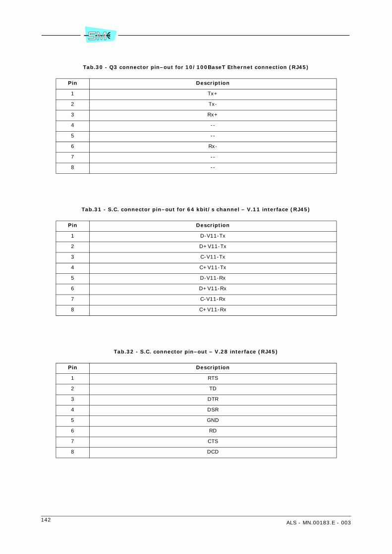
142 ALS - MN.00183.E - 003
Tab.30 - Q3 connector pin–out for 10/100BaseT Ethernet connection (RJ45)
Tab.31 - S.C. connector pin–out for 64 kbit/s channel – V.11 interface (RJ45)
Tab.32 - S.C. connector pin–out – V.28 interface (RJ45)
Pin Description
1 Tx+
2 Tx-
3 Rx+
4 --
5 --
6 Rx-
7 --
8 --
Pin Description
1 D-V11-Tx
2 D+V11-Tx
3 C-V11-Tx
4 C+V11-Tx
5 D-V11-Rx
6 D+V11-Rx
7 C-V11-Rx
8 C+V11-Rx
Pin Description
1 RTS
2 TD
3 DTR
4 DSR
5 GND
6 RD
7 CTS
8 DCD

ALS - MN.00183.E - 003 143
Tab.33 - Connector pin–out – RS232 PPP interface (Sub-D 9 pin male)
Tab.34 - User in/out connector pin–out (Sub-D 9 pin male)
Pin Description
1 DCD
2 RD
3 TD
4 DTR
5 GND
6 DSR
7 RTS
8 CTS
9 NC
Pin Description
1 relay contact
2 NA/NC relay contact
3 User input 01
4 User input 02
5 GND
6 NC
7 User input 03
8 User input 04
9 NC
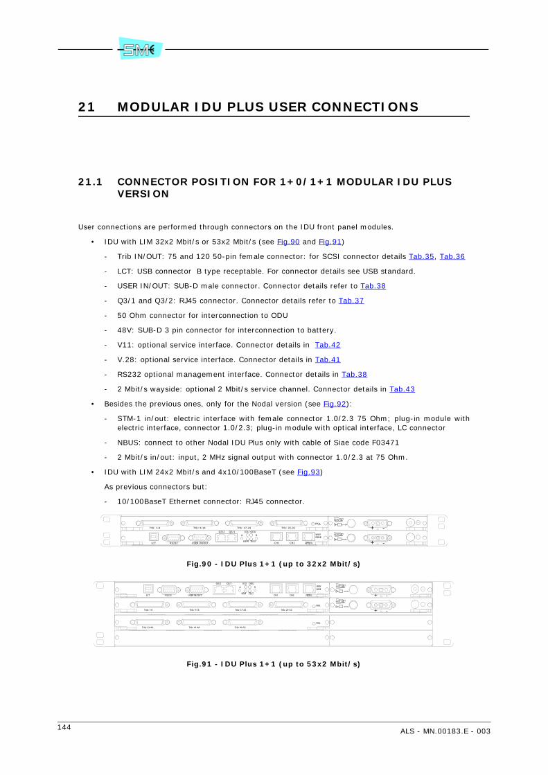
144 ALS - MN.00183.E - 003
21 MODULAR IDU PLUS USER CONNECTIONS
21.1 CONNECTOR POSITION FOR 1+0/1+1 MODULAR IDU PLUS VERSION
User connections are performed through connectors on the IDU front panel modules.
• IDU with LIM 32x2 Mbit/s or 53x2 Mbit/s (see Fig.90 and Fig.91)
- Trib IN/OUT: 75 and 120 50-pin female connector: for SCSI connector details Tab.35, Tab.36
- LCT: USB connector B type receptable. For connector details see USB standard.
- USER IN/OUT: SUB-D male connector. Connector details refer to Tab.38
- Q3/1 and Q3/2: RJ45 connector. Connector details refer to Tab.37
- 50 Ohm connector for interconnection to ODU
- 48V: SUB-D 3 pin connector for interconnection to battery.
- V11: optional service interface. Connector details in Tab.42
- V.28: optional service interface. Connector details in Tab.41
- RS232 optional management interface. Connector details in Tab.38
- 2 Mbit/s wayside: optional 2 Mbit/s service channel. Connector details in Tab.43
• Besides the previous ones, only for the Nodal version (see Fig.92):
- STM-1 in/out: electric interface with female connector 1.0/2.3 75 Ohm; plug-in module withelectric interface, connector 1.0/2.3; plug-in module with optical interface, LC connector
- NBUS: connect to other Nodal IDU Plus only with cable of Siae code F03471
- 2 Mbit/s in/out: input, 2 MHz signal output with connector 1.0/2.3 at 75 Ohm.
• IDU with LIM 24x2 Mbit/s and 4x10/100BaseT (see Fig.93)
As previous connectors but:
- 10/100BaseT Ethernet connector: RJ45 connector.
Fig.90 - IDU Plus 1+1 (up to 32x2 Mbit/s)
Fig.91 - IDU Plus 1+1 (up to 53x2 Mbit/s)
+ -
-+
Q3/1R
IDU ODU
TESTREM
SIDE
2Mb/sCH2CH1RS232 USER IN/OUTLCT
A WAYQ3/2
FAIL
Trib: 1-8 Trib: 9-16 Trib: 17-24 Trib: 25-32
FAIL
Trib: 1-8 Trib: 9-16 Trib: 17-24 Trib: 25-32
Q3/2WAYA
LCT USER IN/OUTRS232 CH1 CH2 2Mb/s
SIDE
REM TEST
ODUIDUR
Q3/1
+ -
-+
FAIL
Trib: 33-40 Trib: 41-48 Trib: 49-53

ALS - MN.00183.E - 003 145
Fig.92 - Nodal IDU Plus 2 units - 16x2 Mbit/s + STM1, 4+0 version
Fig.93 - Modular IDU Plus - 24x2 Mbit/s and 4x10/100BaseT
Tab.35 - Tributary IN/OUT - 75 Ohm
Pin 75 Ohm
48 Ground A
23 Tributary 1/9/17/25/33/41/49 input
50 Ground A
25 Tributary 1/9/17/25/33/41/49 output
47 Ground A
22 Tributary 2/10/18/26/34/42/50 input
45 Ground A
20 Tributary 2/10/18/26/34/42/50 output
42 Ground A
17 Tributary 3/11/19/27/35/43/51 input
43 Ground A
18 Tributary 3/11/19/27/35/43/51 output
40 Ground A
15 Tributary 4/12/20/28/36/44/52 input
39 Ground A
14 Tributary 4/12/20/28/36/44/52 output
36 Ground B
11 Tributary 5/13/21/29/37/45/53 input
37 Ground B
12 Tributary 5/13/21/29/37/45/53 output
34 Ground B
9 Tributary 6/14/22/30/38/46 input
33 Ground B
8 Tributary 6/14/22/30/38/46 output
29 Ground B
4 Tributary 7/15/23/31/39/47 input
Q3/1R
IDU ODU
TESTREM
SIDE
2Mb/sCH2CH1RS232 USER IN/OUTLCT
A WAYQ3/2
+ -
-++ -
-+
FAIL
FAIL
21
NBUS
21
FAIL
Trib: 1-8 Trib: 9-16
ON ON
STM12MHz
Trib: 1-8 Trib: 9-16
FAIL
DPX
ACTLINK1 2 3 4
10-100 BaseT
Trib: 17-24
+ -
-+
48V
Q3/1R
IDUODU
TESTREM
SIDE
2Mb/sCH2CH1RS232 USER IN/OUTLCT
A WAYQ3/2

146 ALS - MN.00183.E - 003
Note: Join pin 44 with ground A pins, join pin 32 with ground B pins.
Fig.94 - Pin-out Tributary 50 pin SCSI female
31 Ground B
6 Tributary 7/15/23/31/39/47 output
28 Ground B
3 Tributary 8/16/24/32/40/48 input
26 Ground B
1 Tributary 8/16/24/32/40/48 output
. . . . . . . . . . . . . . . . . . . . . . . . .
. . . . . . . . . . . . . . . . . . . . . . . . .
125
2650
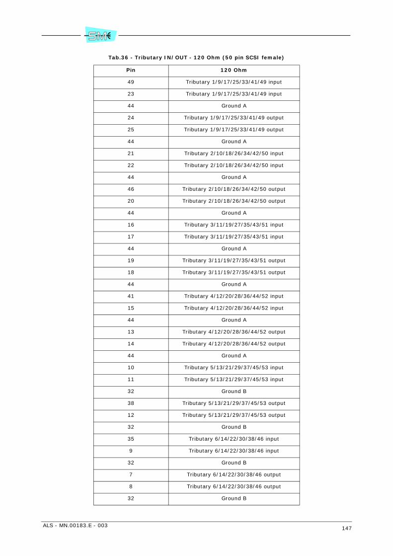
ALS - MN.00183.E - 003 147
Tab.36 - Tributary IN/OUT - 120 Ohm (50 pin SCSI female)
Pin 120 Ohm
49 Tributary 1/9/17/25/33/41/49 input
23 Tributary 1/9/17/25/33/41/49 input
44 Ground A
24 Tributary 1/9/17/25/33/41/49 output
25 Tributary 1/9/17/25/33/41/49 output
44 Ground A
21 Tributary 2/10/18/26/34/42/50 input
22 Tributary 2/10/18/26/34/42/50 input
44 Ground A
46 Tributary 2/10/18/26/34/42/50 output
20 Tributary 2/10/18/26/34/42/50 output
44 Ground A
16 Tributary 3/11/19/27/35/43/51 input
17 Tributary 3/11/19/27/35/43/51 input
44 Ground A
19 Tributary 3/11/19/27/35/43/51 output
18 Tributary 3/11/19/27/35/43/51 output
44 Ground A
41 Tributary 4/12/20/28/36/44/52 input
15 Tributary 4/12/20/28/36/44/52 input
44 Ground A
13 Tributary 4/12/20/28/36/44/52 output
14 Tributary 4/12/20/28/36/44/52 output
44 Ground A
10 Tributary 5/13/21/29/37/45/53 input
11 Tributary 5/13/21/29/37/45/53 input
32 Ground B
38 Tributary 5/13/21/29/37/45/53 output
12 Tributary 5/13/21/29/37/45/53 output
32 Ground B
35 Tributary 6/14/22/30/38/46 input
9 Tributary 6/14/22/30/38/46 input
32 Ground B
7 Tributary 6/14/22/30/38/46 output
8 Tributary 6/14/22/30/38/46 output
32 Ground B
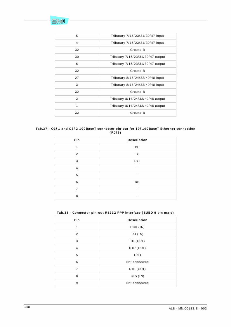
148 ALS - MN.00183.E - 003
Tab.37 - Q3/1 and Q3/2 100BaseT connector pin-out for 10/100BaseT Ethernet connection (RJ45)
Tab.38 - Connector pin-out RS232 PPP interface (SUBD 9 pin male)
5 Tributary 7/15/23/31/39/47 input
4 Tributary 7/15/23/31/39/47 input
32 Ground B
30 Tributary 7/15/23/31/39/47 output
6 Tributary 7/15/23/31/39/47 output
32 Ground B
27 Tributary 8/16/24/32/40/48 input
3 Tributary 8/16/24/32/40/48 input
32 Ground B
2 Tributary 8/16/24/32/40/48 output
1 Tributary 8/16/24/32/40/48 output
32 Ground B
Pin Description
1 Tx+
2 Tx-
3 Rx+
4 --
5 --
6 Rx-
7 --
8 --
Pin Description
1 DCD (IN)
2 RD (IN)
3 TD (OUT)
4 DTR (OUT)
5 GND
6 Not connected
7 RTS (OUT)
8 CTS (IN)
9 Not connected

ALS - MN.00183.E - 003 149
Tab.39 - CH1 connector pin-out for 9600 bit/s synchronous V.24 interface (RJ45)
Tab.40 - CH1 connector pin-out for 9600 bit/s asynchronous V.24 interface (RJ45)
Tab.41 - CH1 connector pin-out for 1x9600 or 2x4800 kbit/s V.28 interface (RJ45)
Pin Description
1 CKTx (OUT)
2 TD (IN)
3 DTR (IN)
4 DSR (OUT)
5 GND
6 RD9600 (OUT)
7 CKRx (OUT)
8 DCD (OUT)
Pin Description
1 --
2 TxD (IN)
3 DTR (IN)
4 DSR
5 GND
6 RxD (OUT)
7 --
8 DCD (OUT)
Pin Description
1 --
2 TD (1° ch 9600 or 4800) (IN)
3 TD (2° ch 4800) (IN)
4 --
5 GND
6 RD (1° ch 9600 or 4800) (OUT)
7 --
8 RD (2° ch 4800) (OUT)

150 ALS - MN.00183.E - 003
Tab.42 - CH2 connector pin-out for 64 kbit/s channel - V.11 interface (RJ45)
Tab.43 - 2 Mbit/s wayside connector pin-out (RJ45)
Tab.44 - User IN/OUT connector pin-out (SUBD 9 pin male)
Pin Description
1 D-V11-Tx
2 D+V11-Tx
3 C-V11-Tx
4 C+V11-Tx
5 D-V11-Rx
6 D+V11-Rx
7 C-V11-Rx
8 C+V11-Rx
Pin Description
1 Tx-C (IN) common
2 TX-F (IN) 120 Ohm
3 GND
4 TX-F (IN) 75 Ohm
5 Rx-C (OUT) common
6 Rx-F (OUT) 120 Ohm
7 GND
8 Rx-F (OUT) 75 Ohm
Pin Description
1 C relay contact- branch 1
2 NA/NC relay contact - branch 1
3 C relay contact - branch 2
4 NA/NC relay contact - branch 2
5 User input 01
6 User input 02
7 User input 03
8 User input 04
9 Ground
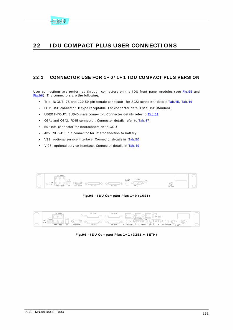
ALS - MN.00183.E - 003 151
22 IDU COMPACT PLUS USER CONNECTIONS
22.1 CONNECTOR USE FOR 1+0/1+1 IDU COMPACT PLUS VERSION
User connections are performed through connectors on the IDU front panel modules (see Fig.95 andFig.96). The connectors are the following:
• Trib IN/OUT: 75 and 120 50-pin female connector: for SCSI connector details Tab.45, Tab.46
• LCT: USB connector B type receptable. For connector details see USB standard.
• USER IN/OUT: SUB-D male connector. Connector details refer to Tab.51
• Q3/1 and Q3/2: RJ45 connector. Connector details refer to Tab.47
• 50 Ohm connector for interconnection to ODU
• 48V: SUB-D 3 pin connector for interconnection to battery.
• V11: optional service interface. Connector details in Tab.50
• V.28: optional service interface. Connector details in Tab.49
Fig.95 - IDU Compact Plus 1+0 (16E1)
Fig.96 - IDU Compact Plus 1+1 (32E1 + 3ETH)
PS
48VDC
-+Trib. 9-16Trib. 1-8
R ALTEST
USER IN/OUTLCTQ3/1Q3/2
V11 RS232
3.15AM250VAC
1
12 2
RS232V11
Q3/2 Q3/1 LCT USER IN/OUT
RXTX12
TESTALR
Trib. 1-8 Trib. 9-16
Trib. 25-32Trib. 17-24
21
+ - -+48VDC 48VDC
PS
1 2
250VACM 3.15A3.15AM 250VAC
10/100 BaseT
1 2 3ACT LINK
DPX

152 ALS - MN.00183.E - 003
Tab.45 - Tributary IN/OUT - 75 Ohm (50 pin SCSI female)
Note: Join pin 44 with ground A pins, join pin 32 with ground B pins.
Fig.97 - Pin-out Tributary 50 pin SCSI female
Pin 75 Ohm
48 Ground A
23 Tributary 1/9/17/25/33/41/49 input
50 Ground A
25 Tributary 1/9/17/25/33/41/49 output
47 Ground A
22 Tributary 2/10/18/26/34/42/50 input
45 Ground A
20 Tributary 2/10/18/26/34/42/50 output
42 Ground A
17 Tributary 3/11/19/27/35/43/51 input
43 Ground A
18 Tributary 3/11/19/27/35/43/51 output
40 Ground A
15 Tributary 4/12/20/28/36/44/52 input
39 Ground A
14 Tributary 4/12/20/28/36/44/52 output
36 Ground B
11 Tributary 5/13/21/29/37/45/53 input
37 Ground B
12 Tributary 5/13/21/29/37/45/53 output
34 Ground B
9 Tributary 6/14/22/30/38/46 input
33 Ground B
8 Tributary 6/14/22/30/38/46 output
29 Ground B
4 Tributary 7/15/23/31/39/47 input
31 Ground B
6 Tributary 7/15/23/31/39/47 output
28 Ground B
3 Tributary 8/16/24/32/40/48 input
26 Ground B
1 Tributary 8/16/24/32/40/48 output
. . . . . . . . . . . . . . . . . . . . . . . . .
. . . . . . . . . . . . . . . . . . . . . . . . .
125
2650

ALS - MN.00183.E - 003 153
Tab.46 - Tributary IN/OUT - 120 Ohm (50 pin SCSI female)
Pin 120 Ohm
49 Tributary 1/9/17/25/33/41/49 input
23 Tributary 1/9/17/25/33/41/49 input
44 Ground A
24 Tributary 1/9/17/25/33/41/49 output
25 Tributary 1/9/17/25/33/41/49 output
44 Ground A
21 Tributary 2/10/18/26/34/42/50 input
22 Tributary 2/10/18/26/34/42/50 input
44 Ground A
46 Tributary 2/10/18/26/34/42/50 output
20 Tributary 2/10/18/26/34/42/50 output
44 Ground A
16 Tributary 3/11/19/27/35/43/51 input
17 Tributary 3/11/19/27/35/43/51 input
44 Ground A
19 Tributary 3/11/19/27/35/43/51 output
18 Tributary 3/11/19/27/35/43/51 output
44 Ground A
41 Tributary 4/12/20/28/36/44/52 input
15 Tributary 4/12/20/28/36/44/52 input
44 Ground A
13 Tributary 4/12/20/28/36/44/52 output
14 Tributary 4/12/20/28/36/44/52 output
44 Ground A
10 Tributary 5/13/21/29/37/45/53 input
11 Tributary 5/13/21/29/37/45/53 input
32 Ground B
38 Tributary 5/13/21/29/37/45/53 output
12 Tributary 5/13/21/29/37/45/53 output
32 Ground B
35 Tributary 6/14/22/30/38/46 input
9 Tributary 6/14/22/30/38/46 input
32 Ground B
7 Tributary 6/14/22/30/38/46 output
8 Tributary 6/14/22/30/38/46 output
32 Ground B

154 ALS - MN.00183.E - 003
Tab.47 - Q3/1 and Q3/2 100BaseT connector pin-out for 10/100BaseT Ethernet connection (RJ45)
Tab.48 - Connector pin-out RS232 PPP interface (RJ45)
5 Tributary 7/15/23/31/39/47 input
4 Tributary 7/15/23/31/39/47 input
32 Ground B
30 Tributary 7/15/23/31/39/47 output
6 Tributary 7/15/23/31/39/47 output
32 Ground B
27 Tributary 8/16/24/32/40/48 input
3 Tributary 8/16/24/32/40/48 input
32 Ground B
2 Tributary 8/16/24/32/40/48 output
1 Tributary 8/16/24/32/40/48 output
32 Ground B
Pin Description
1 Tx+
2 Tx-
3 Rx+
4 --
5 --
6 Rx-
7 --
8 --
Pin Description
1 RTS (OUT)
2 Tx (OUT)
3 DTR (OUT)
4 DSR (IN)
5 GND
6 Rx (IN)
7 CTS (IN)
8 DCD (IN)

ALS - MN.00183.E - 003 155
Tab.49 - V11 connector pin-out for 9600 bit/s asynchronous V.24 interface (RJ45)
Tab.50 - V11 connector pin-out for 1x9600 or 2x4800 kbit/s V.28 asynchronous interface (RJ45)
Tab.51 - V11 connector pin-out for 64 kbit/s channel - V.11 interface (RJ45)
Pin Description
1 RTS (IN)
2 TxD (IN)
3 DTR (IN)
4 DSR (OUT)
5 GND
6 RxD (OUT)
7 CTS (OUT)
8 DCD (OUT)
Pin Description
1 --
2 TD (1° ch 9600 or 4800) (IN)
3 TD (2° ch 4800) (IN)
4 --
5 GND
6 RD (1° ch 9600 or 4800) (OUT)
7 --
8 RD (2° ch 4800) (OUT)
Pin Description for V11Description for
contradirectional
1 D-V11-Tx (IN) D-Tx (IN)
2 D+V11-Tx (IN) D+Tx (IN)
3 C-V11-Tx (OUT)
4 C+V11-Tx (OUT)
5 D-V11-Rx (OUT) D-Rx (OUT)
6 D+V11-Rx (OUT) D+Rx (OUT)
7 C-V11-Rx (OUT)
8 C+V11-Rx (OUT)

156 ALS - MN.00183.E - 003
Tab.52 - User IN/OUT connector pin-out (SUBD 9 pin male)
Pin Description
1 C relay contact
2 NA/NC relay contact
3 User input 01
4 User input 02
5 GND
6 NC
7 User input 03
8 User input 04
9 NC
ALS - MN.00183.E - 003 157
23 INSTALLATION ONTO THE POLE OF THE ODU WITH SEPARATED ANTENNA
23.1 INSTALLATION KIT
Following installation kits are supplied with the equipment depending on different versions:
• 1+0 version
- antisliding strip (see Fig.98)
- supporting plate plus 60–114 mm pole fixing bracket and relevant nuts and bolts (see Fig.99)
- adapting tools and relevant bolts and nuts for 219 mm pole (see Fig.100)
- Band-it fixing system (see Fig.103)
- antenna side flange, variable as function of RF frequency (see Fig.101)
- support with ODU fast locking mechanism (see Fig.99)
- connection to the antenna with flexible wave guide and possible use of a rigid elbow (optional)(see Fig.101)
- kit for ground connection making part of ODU
• 1+0 version (6 GHz only)
Besides the previous items a specific flange adaptor (kit V32409) must be used (see Fig.109). Theflange is UDR70.
• 1+1 version
- antisliding strip (see Fig.98)
- supporting plate plus pole fixing bracket and relevant nuts and bolts (see Fig.99)
- adapting tools and relevant bolts and nuts for 219 mm pole (see Fig.100)
- hybrid with ODU fast locking mechanism (see Fig.102)
- flexible waveguide trunk for connection to antenna (optional) (see Fig.101)
- kit for ground connection making part of the two ODUs.
• 1+1 version (6 GHz only)
Besides the previous items a specific flange adaptor (kit V32415) must be used (see Fig.110). Theflange is UDR70.
• 1+0/1+1 4 GHz version is fully described in chapter 28 INSTALLATION ONTO THE POLE OF THE 4GHz ODU WITH SEPARATED ANTENNA (KIT V32323)
Warning: in order to avoid damages to flexible waveguides, don’t fold or twist them more than valuesspecified as limit in installation instructions of the waveguide supplier.
In case of flexible wave guide use, Tab.55 shows the maximum bending radius.

158 ALS - MN.00183.E - 003
23.2 REQUIRED TOOLS FOR MOUNTING (NOT SUPPLIED)
• N.2 13mm torque wrench
• N.1 15 mm torque wrench
• N.1 17 mm torque wrench
• N.1 3 mm Allen wrench
Warning: if screwing operation concerns more than one screw or bolt, tighten subsequently everyone andits opposite, step by step.
23.3 INSTALLATION PROCEDURE
Installation procedure proceeds according to the following steps:
• Version 1+0: installation onto the pole of the supporting plate 2
• Version 1+0: installation onto the pole of the support plate by Band-it
• Version 1+1: installation onto the pole of the supporting plate 2
• Installation of the ODU (common to both 1+0 and 1+1 version)
• ODU grounding
1+0 version – Installation onto the pole of the supporting plate
Fig.98 – Mount antislide strip around the pole. The position of the plastic blocks depends on the positionof the supporting plate (see next step)
Fig.99 – Adhere the supporting plate to the antisliding strip plastic blocks and then secure it to the polethrough the fixing bracket for 60–114 mm pole (see Fig.99). Bolts and nuts are available on the supportingplate. Tightening torque must be 32 Nm.
Warning: As shown in Fig.100 an adapting kit must be used for the 219 mm pole. It consists of an addi-tional plate to enlarge the standard supporting plate dimension and relevant U–bolt for 219 mm pole fixing.
Fig.101 – Fix the flexible waveguide to the antenna side flange. Four fixing screws are available the dimen-sions of which depend on the waveguide type. Tighten progressively and alternatively the four screws withthe following torque:
Tab.53 - Torques for tightening screws
Fig.101 – Fix the antenna side flange to the support with ODU fast locking mechanism. The flange can bemounted horizontally (as shown in Fig.101) or vertically as function of convenience.
Fig.102 – Fix the support with ODU fast locking mechanism to the supporting plate making use of availablebolts and nuts. Fig.102 shows the possible positions. Tightening torque must be 18 Nm.
2 In case of 219 mm pole, an adapting kit is supplied for the purpose.
Frequencies Screw Tool Torque
from 18 to 38 GHz Allen screw M3 Allen key 2.5 mm 1 Nm
up to 15 GHz Allen screw M4 Allen key 3 mm 2 Nm
ALS - MN.00183.E - 003 159
1+0 version – Installation onto the pole of the supporting plate by Band-it
In case of 1+0 ODU installation, a Band-it pole mounting kit can be used: through slots (see Fig.103) onthe supporting plate two metallic bands secure the plate on the pole. Band characteristics are:
• thickness 0.76 mm
• width 19 mm.
It is also possible to use the anti-sliding system (optional).
1+1 version – Installation onto the pole of the supporting plate
Fig.98 – Mount antislide strip around the pole. The position of the plastic blocks depends on the positionof the supporting plate (see next step)
Fig.99 – Position the supporting plate to the antisliding strip plastic blocks and then secure it to the polethrough the fixing bracket for 60–114 mm pole (see Fig.99). Bolts and nuts are available on the supportingplate kit. Tightening torque must be 32 Nm.
Fig.104 – Secure the hybrid with ODU fast locking mechanism to the supporting plate using bolt and nutsavailable on the support plate. Tightening torque must be 18 Nm.Remove the plastic cover from the hybrid flange sides.
Warning: Do not remove the foil from the hybrid flange sides.
Fig.104 – Fix the flexible waveguide to the antenna side flange. Four fixing screws are available the dimen-sions of which depend on the waveguide type. Tighten progressively and alternatively the four screws withthe following torque:
Tab.54 - Torques for tightening screws
Warning: It is advisable to shape the waveguide flexible trunk, connecting ODU flange with antenna flangeas shown in Fig.107. This avoids possible condensate to be channelled towards the ODU flange.
Installation of the ODU
1 Remove the plastic cover from the ODU flange side. Apply silicon grease e.g. type RHODOSIL PATE4 to the O–ring of Fig.106.Warning: Do not remove the foil from the flange.
2 Bring the ODU with the two hands and position the ODU handle at the bottom side.
3 Position the ODU body close to the support with ODU fast locking mechanism and align ODU sideflange (see Fig.106) to antenna side flange (see Fig.101 – 1+0 version) or hybrid side flange (seeFig.104 – 1+1 version).Note: For 1+0 version the ODU can assume positions of Fig.105 depending on the polarisation.
4 With respect to the flange alignment, turn the ODU body approx. 30° anti–clockwise and then insertthe ODU body into the support and search for alignment between reference tooth on the support(see Fig.101 – 1+0 version or Fig.104 – 1+1 version) and ODU body reference tooth (see detailFig.106)
5 When alignment is achieved, turn the ODU body clockwise until “clack” is heard and the ODU rota-tion stops.
6 Secure ODU body on the support by tightening bolts (1) (see Fig.101 – 1+0 version or Fig.104 –1+1 version). Tightening torque must be 6 Nm.Final assembly of 1+1 version is shown in Fig.107. A parasol mounting is optionally possible.
Frequencies Screw Tool Torque
from 18 to 38 GHz Allen screw M3 Allen key 2.5 mm 1 Nm
up to 15 GHz Allen screw M4 Allen key 3 mm 2 Nm

160 ALS - MN.00183.E - 003
23.4 GROUNDING
The ODU must be connected to ground making reference to details of Fig.108.
Tab.55 - Waveguide bending radius according to frequency
Frequency
Bending radius without rebending
mm (inch)E-plane a
a. Bending E-plane
Bending radius without rebending
mm (inch)H-plane b
b. Bending H-plane
Bending radius with rebending
mm (inch)E-plane a.
Bending radius with rebending
mm (inch)H-plane b.
6 GHz or 7 GHz low
200 (7,9) 500 (19,8) 300 (11,9) 600 (23,7)
7 GHz high 200 (7,9) 500 (19,8) 250 (9,9) 600 (23,7)
11 GHz 130 (5,1) 280 (11,0) 150 (5,9) 300 (11,9)
13 GHz 130 (5,1) 280 (11,0) 150 (5,9) 300 (11,9)
15 GHz 130 (5,1) 280 (11,0) 150 (5,9) 300 (11,9)
18 GHz 130 (5,1) 280 (11,0) 150 (5,9) 300 (11,9)
23 GHz 110 (4,3) 230 (9,1) 130 (5,1) 250 (9,9)
38 GHz 80 (3,1) 140 (5,5) 90 (3,6) 150 (5,9)
Rmin/EBending E-plane
(short side of the section)
Rmin/HBending H-plane
(long side of the section)

ALS - MN.00183.E - 003 161
Fig.98 - Antisliding strip
Antisliding stripPlastic blocks
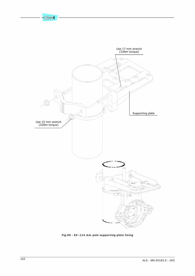
162 ALS - MN.00183.E - 003
Fig.99 - 60–114 mm pole supporting plate fixing
Supporting plate
Use 15 mm wrench(32Nm torque)
Use 17 mm wrench(32Nm torque)
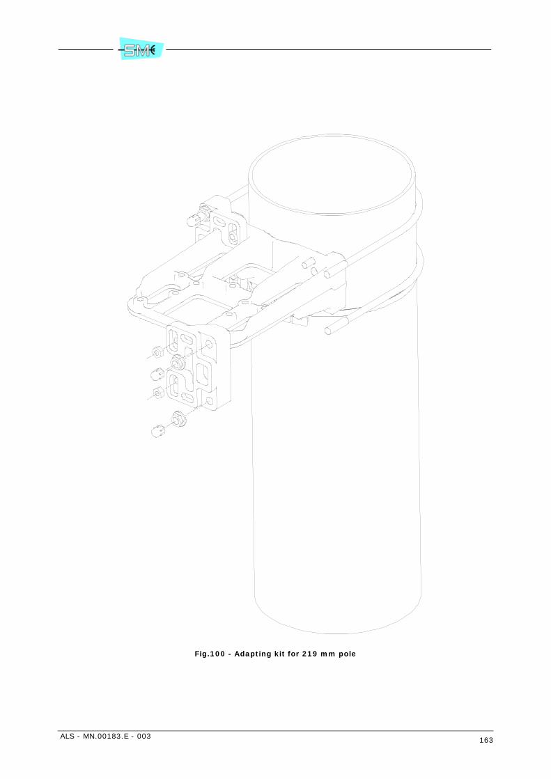
ALS - MN.00183.E - 003 163
Fig.100 - Adapting kit for 219 mm pole
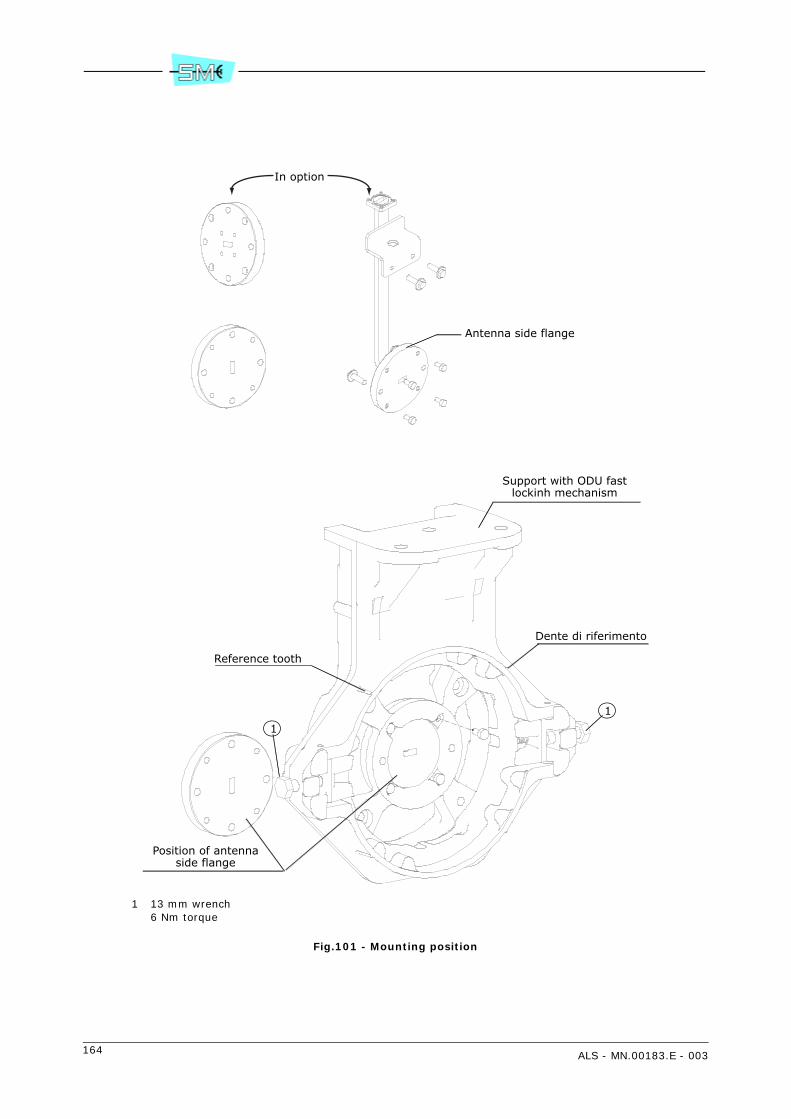
164 ALS - MN.00183.E - 003
1 13 mm wrench6 Nm torque
Fig.101 - Mounting position
Antenna side flange
Support with ODU fastlockinh mechanism
Dente di riferimento
Position of antennaside flange
Reference tooth
1
1
In option
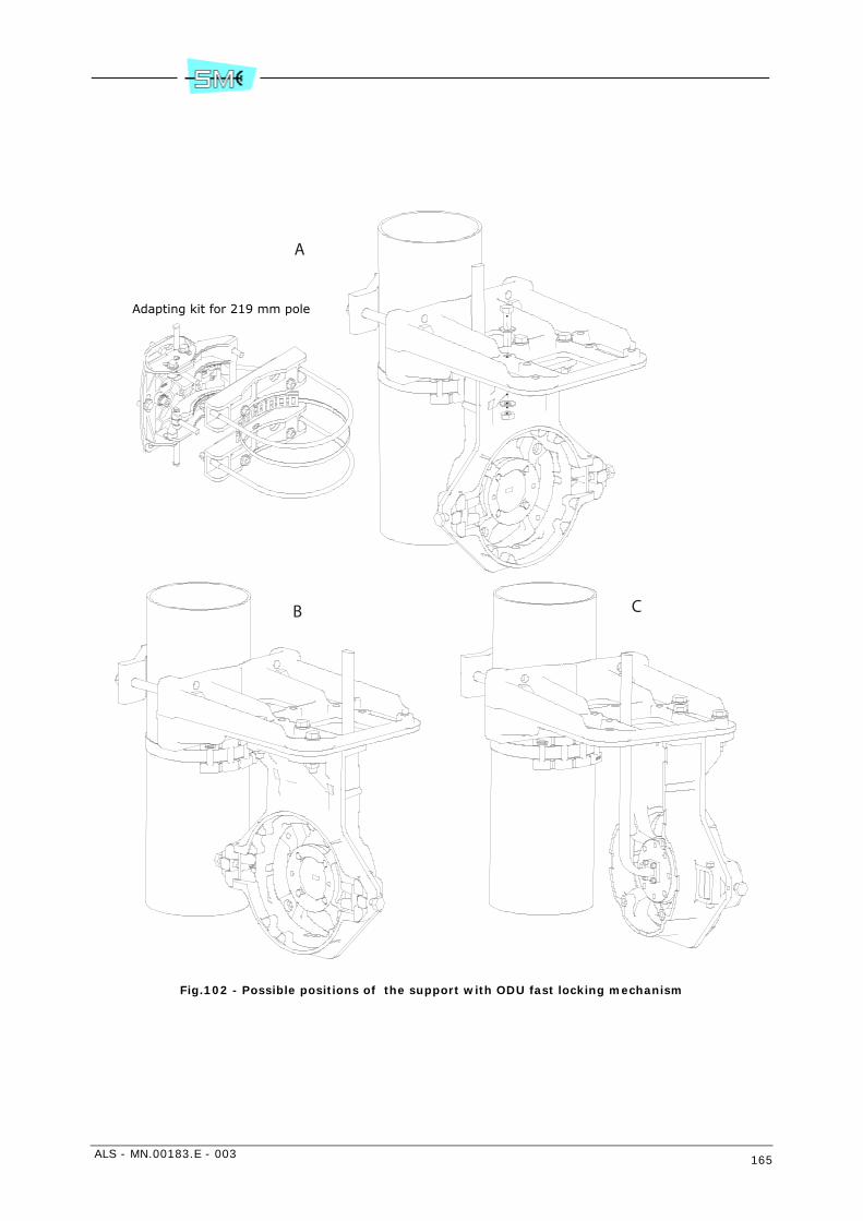
ALS - MN.00183.E - 003 165
Fig.102 - Possible positions of the support with ODU fast locking mechanism
Adapting kit for 219 mm pole
A
B C
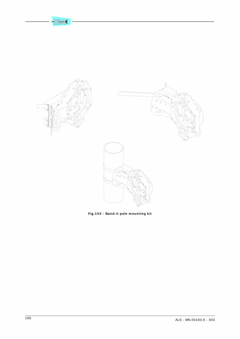
166 ALS - MN.00183.E - 003
Fig.103 - Band-it pole mounting kit
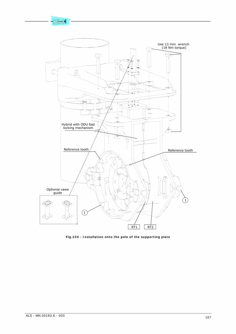
ALS - MN.00183.E - 003 167
Fig.104 - Installation onto the pole of the supporting plate
Use 13 mm wrench (18 Nm torque)
Reference toothReference tooth
Hybrid with ODU fastlocking mechanism
1
1
RT1 RT2
Optional vaweguide
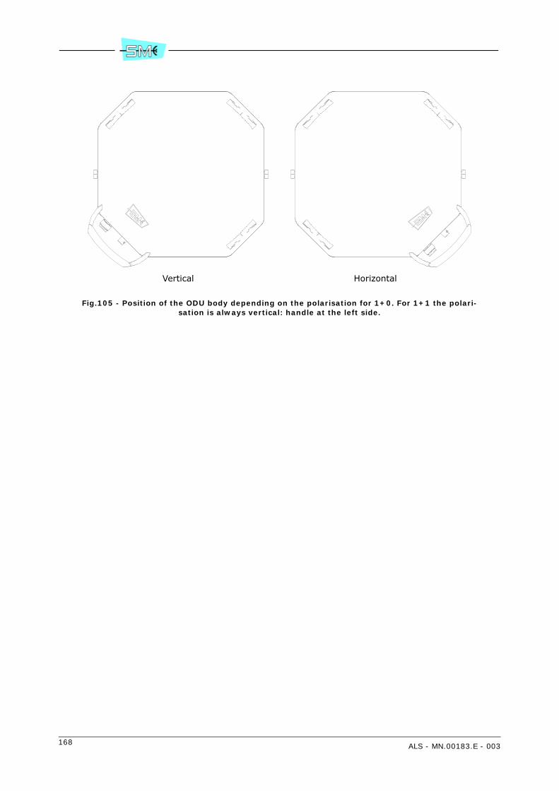
168 ALS - MN.00183.E - 003
Fig.105 - Position of the ODU body depending on the polarisation for 1+0. For 1+1 the polari-sation is always vertical: handle at the left side.
Vertical Horizontal

ALS - MN.00183.E - 003 169
Fig.106 - ODU body reference tooth
"N"
"BNC"
Ground bolt
ODU side flange
Reference tooth
O-ring
AL version
AS version
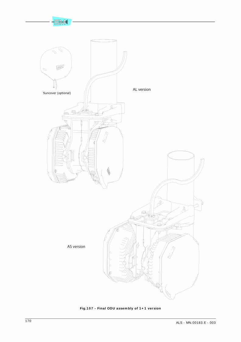
170 ALS - MN.00183.E - 003
Fig.107 - Final ODU assembly of 1+1 version
Suncover (optional)AL version
AS version

ALS - MN.00183.E - 003 171
Fig.108 - ODU grounding
1
2
4
3
5
AL version
AS version

172 ALS - MN.00183.E - 003
Fig.109 - Kit V32409
Screw M4x8
Spring
Washer
Screw M5x25
UDR70 antenna flange
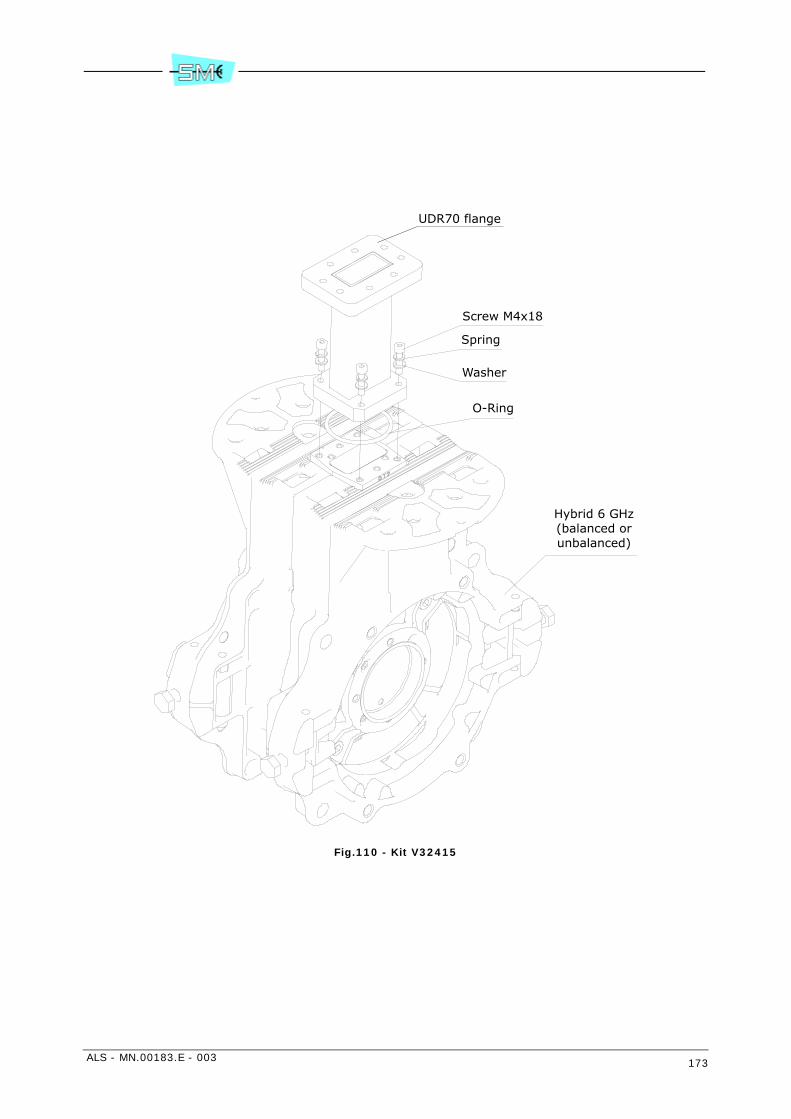
ALS - MN.00183.E - 003 173
Fig.110 - Kit V32415
Spring
Washer
Screw M4x18
O-Ring
Hybrid 6 GHz(balanced orunbalanced)
UDR70 flange

174 ALS - MN.00183.E - 003
24 INSTALLATION ONTO THE WALL OF THE ODU WITH SEPARATED ANTENNA
24.1 INSTALLATION KIT
Following installation kits are supplied with the equipment depending on different versions:
• 1+0 version
- wall supporting plate with additional contact surface extension plates (see Fig.111)
- antenna side flange, variable as function of RF frequency (see Fig.112)
- support with ODU fast locking mechanism (see Fig.112)
- connection to the antenna with flexible wave guide and possible use of a rigid elbow (optional)(see Fig.112)
- kit for ground connection making part of ODU
• 1+0 version (6 GHz only)
Besides the previous items a specific flange adaptor (kit V32409) must be used (see Fig.119). Theflange is UDR70.
• 1+1 version
- supporting plate with additional contact surface extension tools (see Fig.111)
- hybrid with ODU fast locking mechanism (see Fig.114)
- connection to the antenna with flexible wave guide and possible use of a rigid elbow (optional)(see Fig.112)
- kit for ground connection making part of the two ODUs.
• 1+1 version (6 GHz only)
Besides the previous items a specific flange adaptor (kit V32415) must be used (see Fig.120). Theflange is UDR70.
• 1+0/1+1 4 GHz version is fully described in chapter 28 INSTALLATION ONTO THE POLE OF THE 4GHz ODU WITH SEPARATED ANTENNA (KIT V32323)
In case of flexible wave guide use, Tab.58 shows the maximum bending radius.
24.2 REQUIRED TOOLS FOR MOUNTING (NOT SUPPLIED)
• N.2 13mm torque wrench
• N.1 15 mm torque wrench
• N.1 17 mm torque wrench
• N.1 3 mm allen wrench.
Warning: if screwing operation concerns more than one screw or bolt, tighten subsequently everyone andits opposite, step by step.

ALS - MN.00183.E - 003 175
24.3 INSTALLATION PROCEDURE
Installation procedure proceeds according to the following steps:
• version 1+0: installation onto the wall of the supporting plate
• version 1+1: installation onto the wall of the supporting plate
• installation of the ODU (common to both 1+0 and 1+1 version)
• ODU grounding.
1+0 version – Installation onto the wall of the supporting plate
Fig.111 – Fix on the supporting plate the two supplied extension plates to increase the wall contact surface.
Fig.111 – Secure the supporting plate on the wall using the more suitable screws.
Fig.112 – Fix the flexible waveguide to the antenna side flange. Four fixing screws are available the dimen-sions of which depend on the waveguide type. Tighten progressively and alternatively the four screws withthe following torque:
Tab.56 - Torques for tightening screws
Fig.112 – Fix the antenna side flange to the support with ODU fast locking mechanism. The flange can bemounted horizontally (as shown in Fig.112) or vertically as function of convenience.
Fig.113 – Fix the support with ODU fast locking mechanism to the supporting plate making use of availablebolts and nuts. Fig.113 shows three possible positions. Tightening torque must be 18 Nm.
1+1 version – Installation onto the wall of the supporting plate
Fig.111 – Fix on the supporting plate the two supplied extension plates to increase the wall contact surface.
Fig.111 – Secure the supporting plate on the wall using the more suitable screws.
Fig.114 – Secure the hybrid with ODU fast locking mechanism to the supporting plate using bolt and nutsavailable on the support plate. Tightening torque must be 18 Nm.Remove the plastic cover from the hybrid flange sides.
Warning: Do not remove the foil from the hybrid flange sides.
Fig.114 – Fix the flexible waveguide to the antenna side flange. Four fixing screws are available the dimen-sions of which depend on the waveguide type. Tighten progressively and alternatively the four screws withthe following torque:
Tab.57 - Torques for tightening screws
Warning: It is advisable to shape the waveguide flexible trunk, connecting ODU flange with antenna flangeas shown in Fig.117 This avoids possible condensate to be channelled towards the ODU flange.
Frequencies Screw Tool Torque
from 18 to 38 GHz Allen screw M3 Allen key 2.5 mm 1 Nm
up to 15 GHz Allen screw M4 Allen key 3 mm 2 Nm
Frequencies Screw Tool Torque
from 18 to 38 GHz Allen screw M3 Allen key 2.5 mm 1 Nm
up to 15 GHz Allen screw M4 Allen key 3 mm 2 Nm

176 ALS - MN.00183.E - 003
Installation of the ODU
1 Remove the plastic cover from the ODU flange side. Apply silicon grease e.g. type RHODOSIL PATE4 to the O–ring of Fig.116.Warning: Do not remove the foil from the flange.
2 Bring the ODU with the two hands and position the ODU handle at the bottom side.
3 Position the ODU body close to the support with ODU fast locking mechanism and align ODU sideflange (see Fig.116) to antenna side flange (see Fig.112 – 1+0 version) or hybrid side flange (seeFig.114 – 1+1 version).
Note: For 1+0 version the ODU can assume positions of Fig.115 depending on the polarisation.
4 With respect to the flange alignment, turn the ODU body approx. 30° anti–clockwise and then insertthe ODU body into the support and search for alignment between reference tooth on the support(see Fig.112 – 1+0 version or Fig.114 – 1+1 version) and ODU body reference tooth (see detailFig.116)
5 When alignment is achieved, turn the ODU body clockwise until “clack” is heard and the ODU rota-tion stops.
6 Secure ODU body on the support by tightening bolts (1) (see Fig.112 – 1+0 version or Fig.114 –1+1 version). Tightening torque must be 6 Nm.
Final assembly of 1+1 version is shown in Fig.117. A parasol mounting is optionally possible.
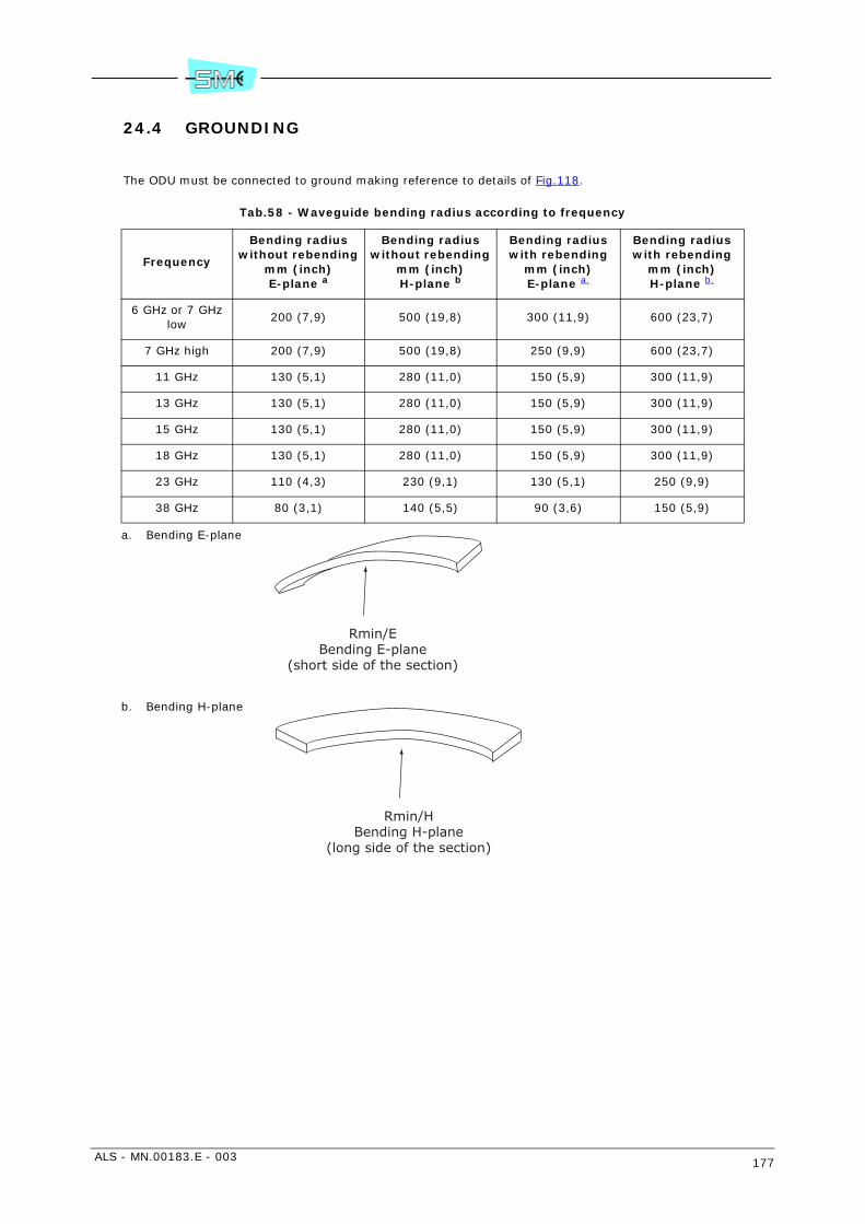
ALS - MN.00183.E - 003 177
24.4 GROUNDING
The ODU must be connected to ground making reference to details of Fig.118.
Tab.58 - Waveguide bending radius according to frequency
Frequency
Bending radius without rebending
mm (inch)E-plane a
a. Bending E-plane
Bending radius without rebending
mm (inch)H-plane b
b. Bending H-plane
Bending radius with rebending
mm (inch)E-plane a.
Bending radius with rebending
mm (inch)H-plane b.
6 GHz or 7 GHz low
200 (7,9) 500 (19,8) 300 (11,9) 600 (23,7)
7 GHz high 200 (7,9) 500 (19,8) 250 (9,9) 600 (23,7)
11 GHz 130 (5,1) 280 (11,0) 150 (5,9) 300 (11,9)
13 GHz 130 (5,1) 280 (11,0) 150 (5,9) 300 (11,9)
15 GHz 130 (5,1) 280 (11,0) 150 (5,9) 300 (11,9)
18 GHz 130 (5,1) 280 (11,0) 150 (5,9) 300 (11,9)
23 GHz 110 (4,3) 230 (9,1) 130 (5,1) 250 (9,9)
38 GHz 80 (3,1) 140 (5,5) 90 (3,6) 150 (5,9)
Rmin/EBending E-plane
(short side of the section)
Rmin/HBending H-plane
(long side of the section)
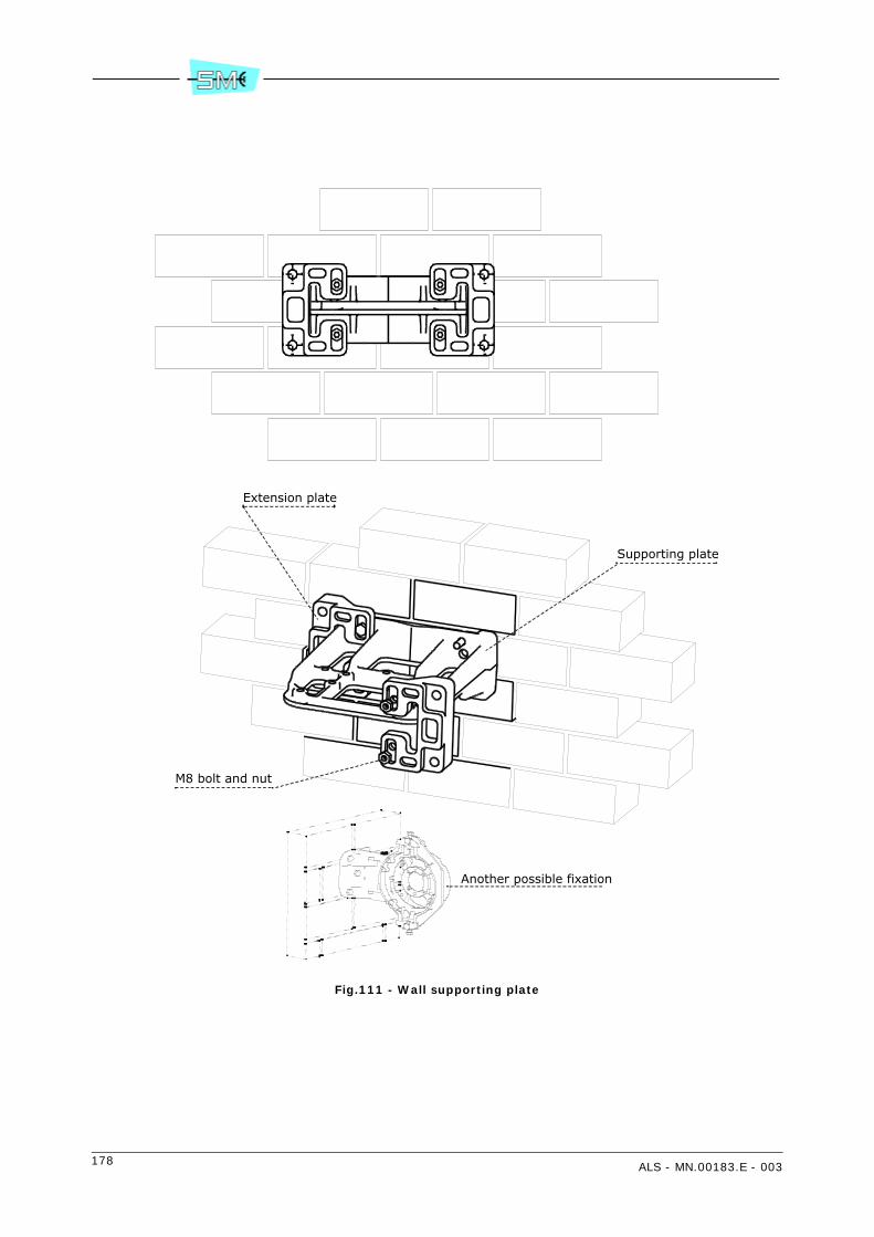
178 ALS - MN.00183.E - 003
Fig.111 - Wall supporting plate
Extension plate
Supporting plate
M8 bolt and nut
Another possible fixation
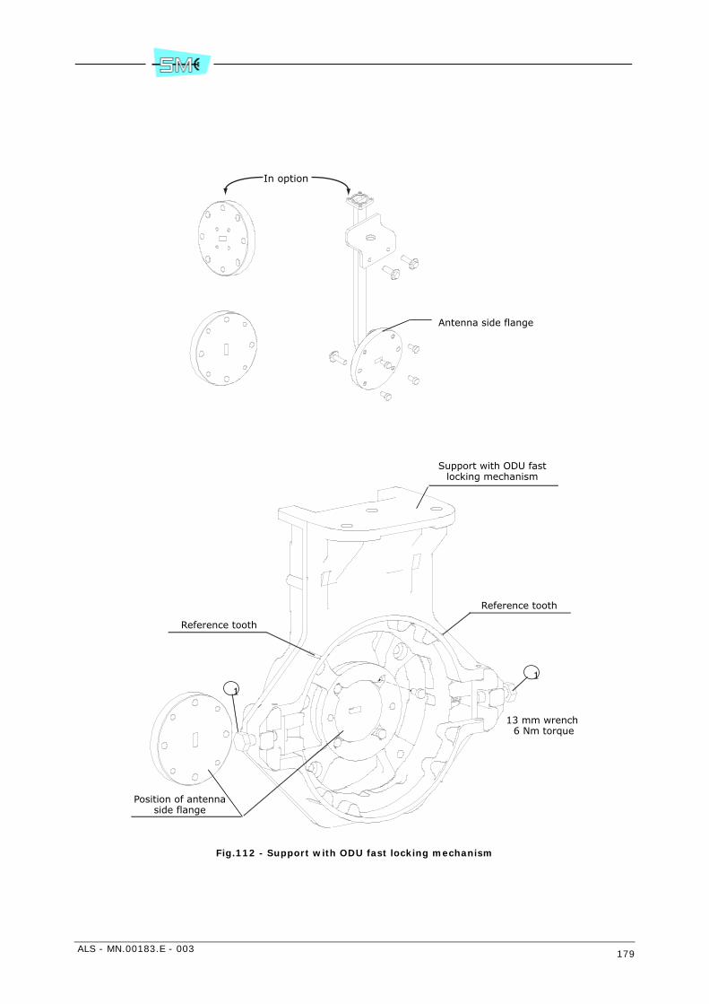
ALS - MN.00183.E - 003 179
Fig.112 - Support with ODU fast locking mechanism
Antenna side flange
Support with ODU fastlocking mechanism
Reference tooth
Position of antennaside flange
Reference tooth
1
1
13 mm wrench 6 Nm torque
In option

180 ALS - MN.00183.E - 003
Fig.113 - Mounting possible positions
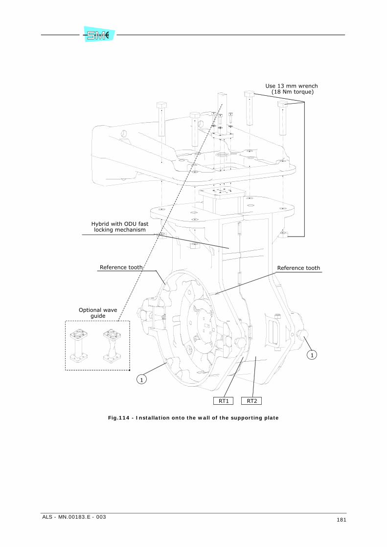
ALS - MN.00183.E - 003 181
Fig.114 - Installation onto the wall of the supporting plate
Use 13 mm wrench (18 Nm torque)
Reference tooth
Hybrid with ODU fastlocking mechanism
1
1
RT1 RT2
Optional waveguide
Reference tooth
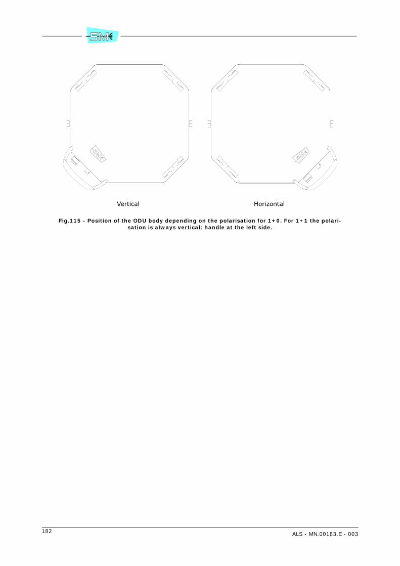
182 ALS - MN.00183.E - 003
Fig.115 - Position of the ODU body depending on the polarisation for 1+0. For 1+1 the polari-sation is always vertical: handle at the left side.
Vertical Horizontal
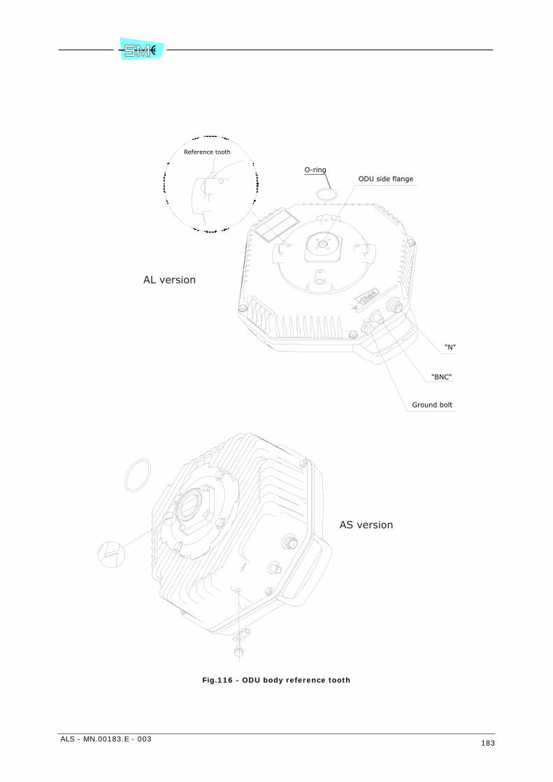
ALS - MN.00183.E - 003 183
Fig.116 - ODU body reference tooth
"N"
"BNC"
Ground bolt
ODU side flange
Reference tooth
O-ring
AS version
AL version
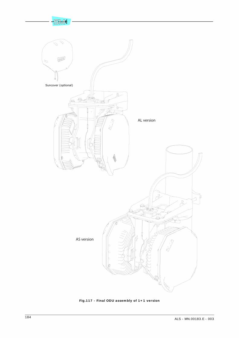
184 ALS - MN.00183.E - 003
Fig.117 - Final ODU assembly of 1+1 version
Suncover (optional)
AS version
AL version

ALS - MN.00183.E - 003 185
1 Bolt
2 Spring washer
3 Flat washer
4 Earth cable collar
5 Flat washer
Fig.118 - ODU grounding
1
2
4
3
5
AS version
AL version

186 ALS - MN.00183.E - 003
Fig.119 - Kit V32409
Screw M4x8
Spring
Washer
Screw M5x25
UDR70 antenna flange

ALS - MN.00183.E - 003 187
Fig.120 - Kit V32415
Spring
Washer
Screw M4x18
O-Ring
Hybrid 6 GHz(balanced orunbalanced)
UDR70 flange
188 ALS - MN.00183.E - 003
25 INSTALLATION ONTO THE POLE OF THE ODU WITH INTEGRATED ANTENNA
25.1 FOREWORD
The installation onto the pole of the ODU with integrated antenna concerns both 1+0 and 1+1 versions.
25.2 INSTALLATION KIT
Following installation kits are supplied with the equipment depending on different versions:
1+0 version
• 60 to 114 mm pole mounting kit consisting of:
- centring ring and relevant screws (see Fig.121)
- antislide strip (see Fig.122)
- pole support system and pole fixing brackets (see Fig.123)
- ODU with O–ring and devices for ground connection
1+1 version
• pole mounting kit from 60 to 114 mm for 1+1 consisting of:
- centring ring and relevant screws (see Fig.121)
- antislide strip (see Fig.122)
- pole support system and pole fixing brackets (see Fig.123)
• hybrid mechanical body (see Fig.132)
• polarization twist disk (see Fig.134)
• 2 ODUs with O–rings and devices for ground connection.
ALS - MN.00183.E - 003 189
25.3 REQUIRED TOOLS FOR MOUNTING (NOT SUPPLIED)
• N.2 13 mm torque wrench
• N.1 15 mm torque wrench
• N.1 17 mm torque wrench
• N.1 3 mm allen wrench.
Warning: if screwing operation concerns more than one screw or bolt, tighten subsequently everyone andits opposite, step by step.
25.4 INSTALLATION PROCEDURE
Installation procedure proceeds according with the following steps:
1+0 version
1 installation onto the pole of the support system
2 installation of the antenna
3 installation of ODU
4 antenna aiming
5 ODU grounding
1+1 version
1 installation onto the pole of the support system
2 installation of the antenna
3 installation of hybrid circuit
4 installation of the two ODUs
5 antenna aiming
6 ODU grounding.
25.4.1 Installation onto the pole of the support system and the antenna
Fig.121 – Set the antenna in such a position as to be able to operate on its rear side. Locate the five thread-ed holes around antenna flange. Mount centring ring onto antenna flange and tight it with 3 calibratedbolts.Caution: centring ring should be mounted so that the screws do not stick out.
Define if the antenna will be mounted with vertical or horizontal polarization. Check that free drain holesstay at bottom side. Mount bolt type M10x30, in position A leaving it loose of 2 cm approx. With horizontalpolarization mount bolt type M10x30 in position D, leaving it loose of 2 cm approx.
Fig.122 – Mount antislide strip onto the pole. Place blocks as in Fig.122 following antenna aiming direction.Tighten the strip with screwdriver.
Fig.123 – Mount pole supporting system with relevant pole fixing brackets following antenna aiming direc-tion as indicated by arrow. Antislide strip should result at the centre of supporting plate. Supporting systemshould lean against antislide clamp with the tooth as in Fig.124. Position the antenna in such a way that

190 ALS - MN.00183.E - 003
bolt in position A or D of Fig.121 cross through hole E of Fig.125. Secure the support system to the poleby means of the pole fixing brackets and relevant fixing bolts.
Fig.126 – Rotate the antenna body until the remainder three antenna holes coincide with the three supportholes. Secure the antenna to the support by thightening the relevant passing through bolts.
25.4.2 Installation of ODU
1+0 version
1 Apply silicon grease e.g. RHODOSIL PATE 4” to the O–ring (4) of Fig.129 by protecting finger handswith gloves.
2 Bring the ODU with the two hands and position the ODU handle at the bottom side. The ODU handlecan assume position of Fig.127 depending on the polarization.
3 Position the ODU body near the support system and align ODU side flange to antenna side flange(see Fig.128). With respect to the flange alignment, turn the ODU body approx. 30° anti–clockwiseand then insert the ODU body into the support and search for alignment between reference toothon the support (see Fig.128) and ODU body reference tooth (see detail of Fig.129).
4 When alignment is achieved, turn the ODU body clockwise until “clack” is heard and the ODU rota-tion stops.Fig.130 and Fig.131 show ODU housing final position for vertical and horizontal polarization respec-tively.
5 Secure ODU body on the support system by tightening bolts (1) of Fig.128.
1+1 version
Fig.132 – Apply silicon grease, type “RHODOSIL PATE 4” to O–rings (1). Insert O–rings (1) and (6) intotwist polarization disk (2).
Vertical polarization
Fix the disk on hybrid flange placing marker (4), on disk, close to V mark.
Horizontal polarization
Fix the disk on hybrid flange placing reference (4), on disk, close to H mark.
In 13 GHz and 15 GHz ODUs the polarization disk is fixed to the hybrid flange by means of 3 screws asshown in Fig.133.
Caution: Twist disk has two planes. Take care of position marker (4) on twist disk. The position of marker(4) plane should be in contact to hybrid like in figure. Tighten progressively and alternatively screws (7)with the same number of spring washers (8) with the following torque:
Tab.59 - Torques for tightening screws
Fig.134 – Fix hybrid to support system with four bolts (1) taking care of RT1/RT2 position shown by labelsof Fig.134. Tighten progressively and alternatively four bolts (1).
Frequencies Screw Tool Torque
from 18 to 38 GHz Allen screw M3 Allen key 2.5 mm 1 Nm
up to 15 GHz Allen screw M4 Allen key 3 mm 2 Nm

ALS - MN.00183.E - 003 191
25.4.3 ODU installation
The installation procedure of the two ODUs is the same.
1 Apply silicon grease e.g. RHODOSIL PATE 4” to the O–ring (4) of the Fig.129 by protecting fingerhands with gloves.
2 Bring the ODU with the two hands and position the ODU handle at the bottom side. For 1+0 theODU can assune position of Fig.127 depending on the polarisation. For 1+1 the handle ODU positionis always placed at the right side (horizontal polarization).
3 Position the ODU body near the support system and align ODU side flange to antenna side flange(see Fig.128). With respect to the flange alignment, turn the ODU body approx. 30° anti–clockwiseand then insert the ODU body into the support and search for alignment between reference toothon the support (see Fig.128) and ODU body reference tooth (see detail of Fig.129).
4 When alignment is achieved, turn the ODU body clockwise until “clack” is heard and the ODU rota-tion stops.Fig.130 and Fig.131 show ODU housing final position for vertical and horizontal polarization respec-tively for 1+0 version.Fig.135 shows ODU housing final position for 1+1 version.
5 Secure ODU body on the support system by tightening bolts (1) of Fig.128.
25.5 ANTENNA AIMING
Antenna aiming for 1+0 version and 1+1 version is the same. The antenna aiming devices allow to performthe following adjustments with respect to the starting aiming position:
- Horizontal ± 15° operating on the nut (3) shown in Fig.136, only after having loosenthe nuts (7), (8), (9), (10) of Fig.137.
- vertical ± 15° operating on vertical adjustment worm screw (2) shown in Fig.136only after having loosen nuts (1), (2), (11) of Fig.137 and (4) and (5) of Fig.136.For adjustment from 0° to +30° extract nut (1) Fig.137 and position it inhole (4), extract nut (2) Fig.137 and position it in hole (6). Operate on vertical adjustment worm screw (2) after having loosen nuts (1), (2), (11) ofFig.137 and (4) of Fig.136.For adjustment from 0° to –30° extract nut (1) of Fig.137 and position it inhole (3), extract nut (2) of Fig.137 and position it in hole (5). Operate onvertical adjustment worm screw (2) after having loosen nuts (1), (2), (11) ofFig.137 and (4) of Fig.136.
For vertical adjustment some markers, every 10°, are available on support.The bigger marker gives 0° starting aiming position. Once the optimum aimingposition is obtained, tighten firmly the four nuts (1), (2), (11) of Fig.137 and(4) and (5) of Fig.136 for vertical adjustment and the four nuts (7), (8), (9),(10) of Fig.137 for horizontal adjustment. Tighten with 15 mm wrench and32 Nm torque.
25.6 COMPATIBILITY
The pole installation kit of the ODU unit in 1+0 and 1+1 configuration is compatible with integrated antennacomplying with SIAE standard with measures 0.2 m, 0.4 m, 0.6 m, 0.8 m of diameter.

192 ALS - MN.00183.E - 003
25.7 GROUNDING
See Fig.138.
On ODU grounding can be connected with the available bolt spring washer and flat washers as shown.
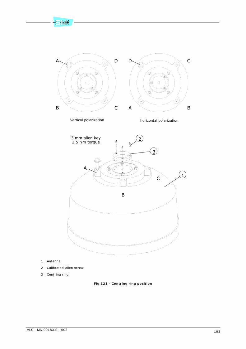
ALS - MN.00183.E - 003 193
1 Antenna
2 Calibrated Allen screw
3 Centring ring
Fig.121 - Centring ring position
A
B C
D D
A B
C
A
B
C1
2
3
horizontal polarizationVertical polarization
3 mm allen key2,5 Nm torque

194 ALS - MN.00183.E - 003
1 Steel belt
2 Plastic blocks
Fig.122 - Antislide strip
1
2

ALS - MN.00183.E - 003 195
1 Pole fixing brackets
2 Tooth
3 Bolt
4 Pole support system
Fig.123 - Support mount on pole
2
3Antenna aiming direction
15 mm wrench32 Nm torque
1
3
1
3
3 3
3

196 ALS - MN.00183.E - 003
1 Tooth
Fig.124 - Supporting system position
Fig.125 - Hole E
1
Antenna aiming direction
E
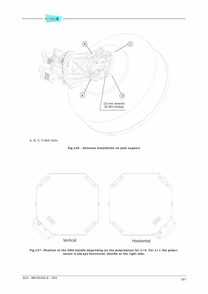
ALS - MN.00183.E - 003 197
A, B, C, D Bolt slots
Fig.126 - Antenna installation on pole support
Fig.127 -Position of the ODU handle depending on the polarisation for 1+0. For 1+1 the polari-sation is always horizontal. Handle at the right side.
DA
B C
15 mm wrench32 Nm torque
Vertical Horizontal

198 ALS - MN.00183.E - 003
H: Reference tooth
Fig.128 - Support system for ODU housing and reference tooth in evidence
1
1
1
H
H
H
H
HH
HH
13 mm wrench6 Nm torque
1
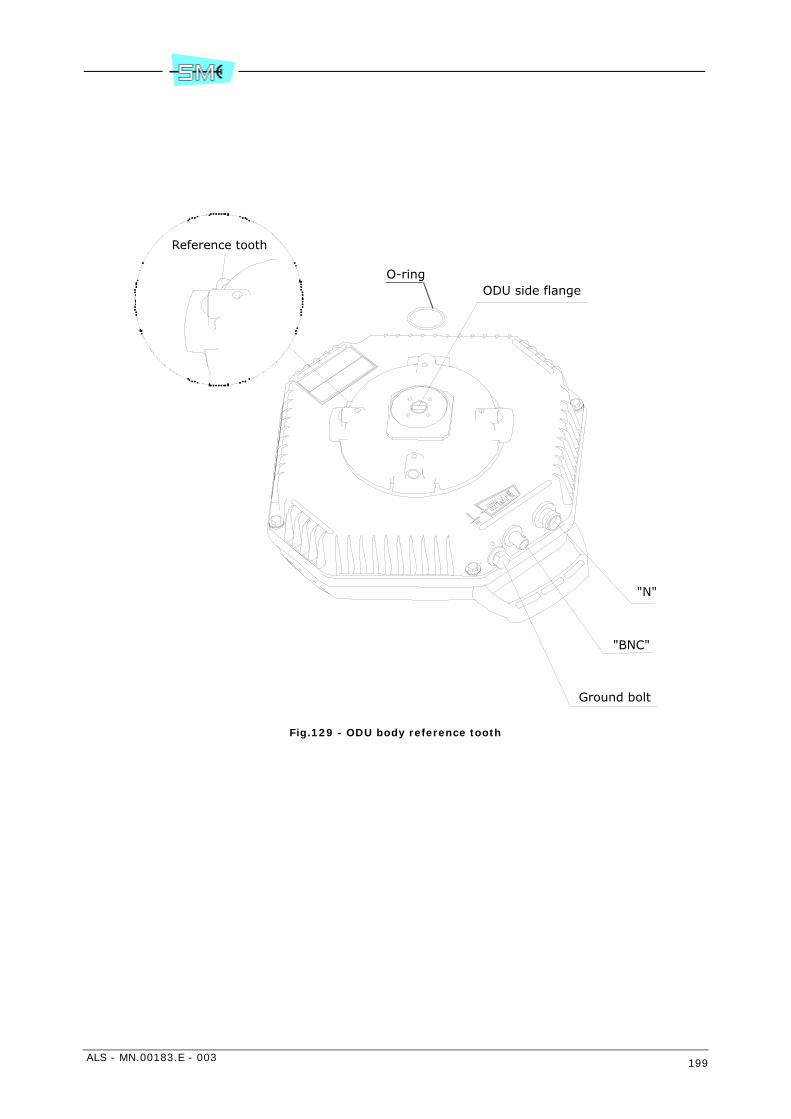
ALS - MN.00183.E - 003 199
Fig.129 - ODU body reference tooth
"N"
"BNC"
Ground bolt
ODU side flange
Reference tooth
O-ring
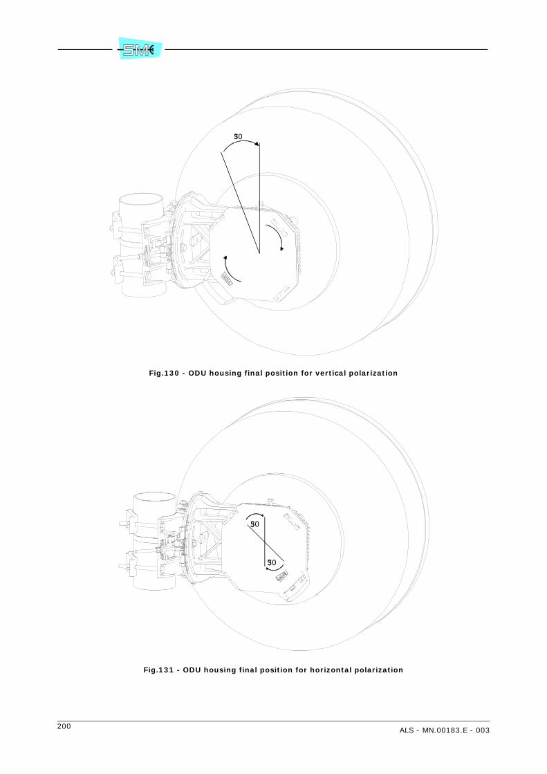
200 ALS - MN.00183.E - 003
Fig.130 - ODU housing final position for vertical polarization
Fig.131 - ODU housing final position for horizontal polarization
305
305
305

ALS - MN.00183.E - 003 201
1 O–ring
2 Polarization twist disk
3 Hybrid mechanical body
4 Position marker of twist disk
5 Reference label for twist disk
6 O–ring
7 Allen screws
8 Spring washer
Fig.132 - Hybrid and polarization disk
2
1
3
4
5
6
7
8
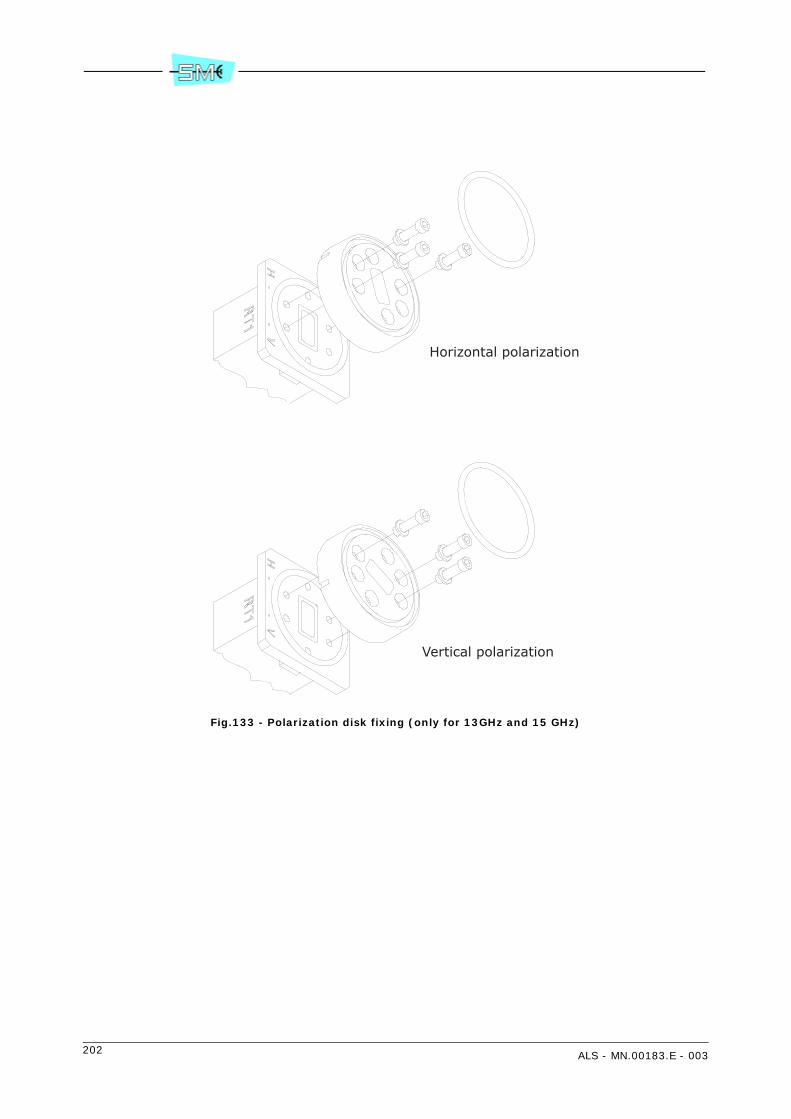
202 ALS - MN.00183.E - 003
Fig.133 - Polarization disk fixing (only for 13GHz and 15 GHz)
Horizontal polarization
Vertical polarization

ALS - MN.00183.E - 003 203
1 Bolts
2 Spring washer
Fig.134 - Hybrid mount on pole support
21
1
13 mm wrench18 Nm torque
RT2
RT1
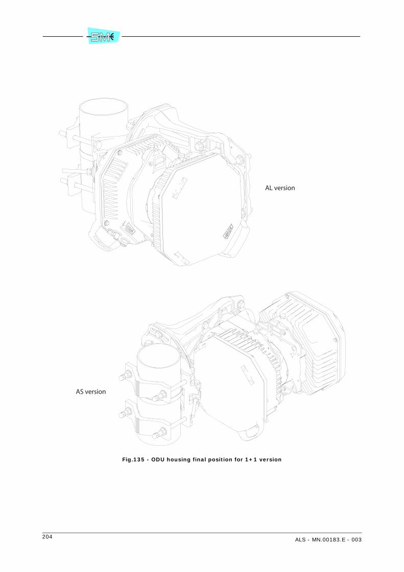
204 ALS - MN.00183.E - 003
Fig.135 - ODU housing final position for 1+1 version
AL version
AS version

ALS - MN.00183.E - 003 205
1 Marker
2 Vertical adjustment
3 Horizontal adjustment
4 Bolt
5 Fixing nut
Fig.136 - Vertical and horizontal adjustments
12
34
5
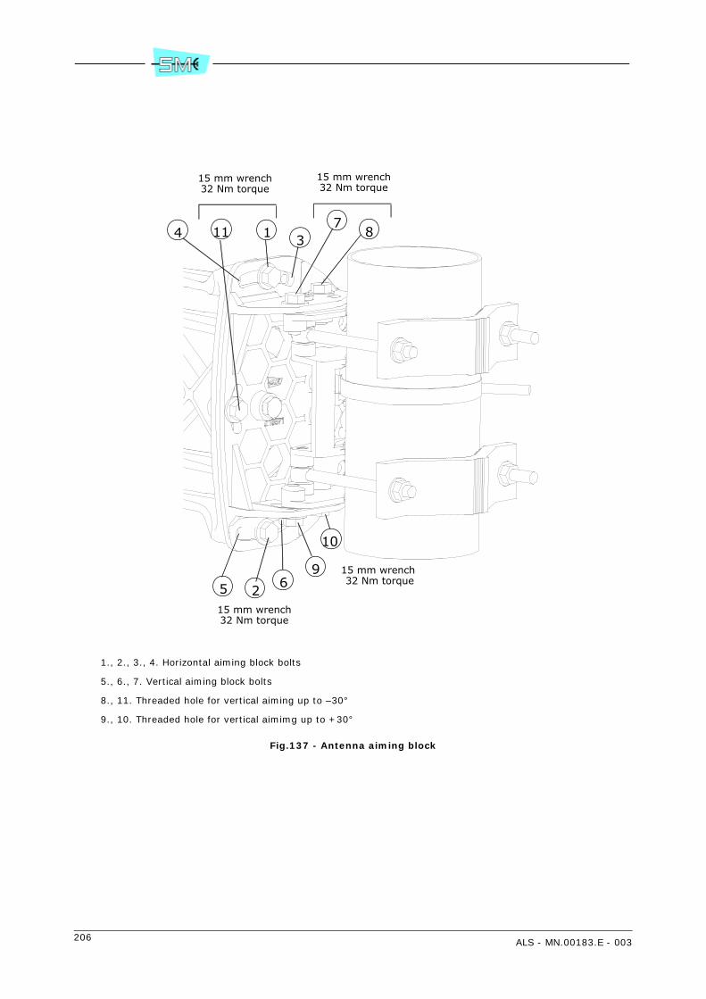
206 ALS - MN.00183.E - 003
1., 2., 3., 4. Horizontal aiming block bolts
5., 6., 7. Vertical aiming block bolts
8., 11. Threaded hole for vertical aiming up to –30°
9., 10. Threaded hole for vertical aimimg up to +30°
Fig.137 - Antenna aiming block
2
1 3
5
4
69
10
87
11
15 mm wrench32 Nm torque
15 mm wrench32 Nm torque
15 mm wrench 32 Nm torque
15 mm wrench32 Nm torque
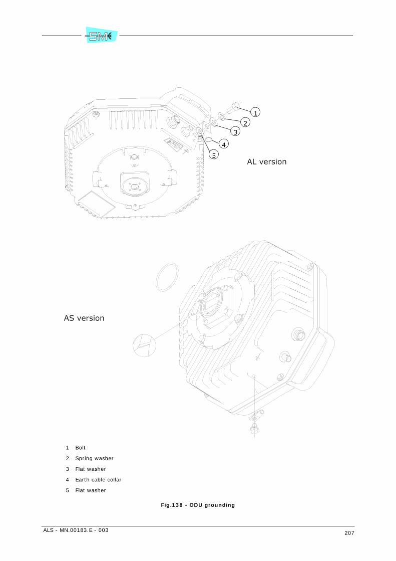
ALS - MN.00183.E - 003 207
1 Bolt
2 Spring washer
3 Flat washer
4 Earth cable collar
5 Flat washer
Fig.138 - ODU grounding
1
2
4
3
5AL version
AS version

208 ALS - MN.00183.E - 003
26 INSTALLATION ONTO THE POLE OF THE ODU WITH INTEGRATED ANTENNA (KIT V32307, V32308, V32309)
26.1 FOREWORD
The description concerns pole mounting of ODU, in 1+0 and 1+1 version, using following installation kits:
- V32307 for ODU with frequency from 10 to 13 GHz
- V32308 for ODU with frequency from 15 to 38 GHz
- V32309 for ODU with frequency from 7 to 8 GHz
Differences regard the dimensions and the presence of the centring ring (see Fig.139):
- V32307 centring ring for antenna flange from 10 to 13 GHz
- V32308 centring ring for antenna flange from 15 to 38 GHz
- V32309 no centring ring (and relevant screws).
26.2 INSTALLATION KIT
Following installation kits are supplied with the equipment depending on different versions.
1+0 version
• 60 to 129 mm pole mounting kit:
- centring ring and relevant screws
- pole support system plus antenna (already assembled) and pole fixing brackets
- 1+0 ODU support and relevant screws
- ODU with O–ring and devices for ground connection
1+1 version
• 60 to 129 mm pole mounting kit:
- centring ring and relevant screws
- pole support system plus antenna (already assembled) and pole fixing brackets
- 1+0 ODU support
- hybrid and relevant screws
- polarization twist disk and relevant screws
- 2 ODUs with O–rings and devices for ground connection.
ALS - MN.00183.E - 003 209
26.3 REQUIRED TOOLS FOR MOUNTING (NOT SUPPLIED)
• N.1 2.5 mm Allen wrench
• N.1 3 mm Allen wrench
• N.1 6 mm Allen wrench
• N.1 13 mm spanner
• N.2 17 mm spanner.
Warning: if screwing operation concerns more than one screw or bolt, tighten subsequently everyone andits opposite, step by step.
26.4 INSTALLATION PROCEDURE
Installation procedure is listed below:
1+0 version
1 antenna polarization
2 installation of the centring ring on the antenna
3 installation of 1+0 ODU support
4 installation onto the pole of the assembled structure
5 installation of ODU
6 antenna aiming
7 ODU grounding
1+1 version
1 antenna polarization
2 installation of the centring ring on the antenna
3 installation of 1+0 ODU support
4 installation onto the pole of the assembled structure
5 installation of hybrid
6 installation of ODUs
7 antenna aiming
8 ODU grounding.
210 ALS - MN.00183.E - 003
26.5 1+0 MOUNTING PROCEDURES
26.5.1 Setting antenna polarization
Fig.139 – Set the antenna in such a position to operate on its rear side. Locate the four M3 Allen screwsaround the antenna flange. Unscrew them (use 2.5 mm Allen wrench) and position the antenna flange ac-cording on: horizontal wave guide –> vertical polarization, vertical wave guide –> horizontal polariza-tion. Screw again the four Allen screws (torque = 1 Nm).
26.5.2 Installation of the centring ring on the antenna
Fig.139 – Set the antenna in such a position to operate on its rear side. Locate the three holes around theantenna flange. Mount the centring ring onto antenna flange and tight it with the 3 Allen screws M4 (use3mm Allen wrench, torque 2 = Nm).
26.5.3 Installation of 1+0 ODU support
Fig.139 – Mount the support onto assembled structure (pole support system plus antenna) using the fourM8 Allen screws (use 6 mm Allen wrench, torque 18 = Nm). Two of the four screws, diagonally opposed,must be mounted with the two bushes around.
26.5.4 Installation onto the pole of the assembled structure
Fig.139 – Mount the assembled structure on the pole using the two pole fixing brackets and the four M10screws (use 17 mm spanner, torque = 13 Nm); the heads of the screws are inserted on the antenna side,the four nuts and the springs between nut and brackets are inserted on bracket side.
26.5.5 Installation of ODU (on 1+0 support)
Fig.140 – Apply silicon grease (e.g. RHODOSIL PATE 4”) on the O–ring by protecting fingers with gloves.
Fig.141 – Bring the ODU with the two hands and position the ODU handle at the bottom side. The handlecan assume the positions shown in the figure depending on the polarization. Position the ODU body nearthe support and align the wave guide of the ODU to the Wave guide of the antenna: respect to the positionof wave guide alignment, turn the ODU body approx. 30° counter–clockwise into the support and searchfor matching between reference tooth on the support (see Fig.142) and reference tooth on the ODU body.
Fig.143 – When alignment of the references teeth is achieved, turn the ODU body clockwise until rotationis stopped. In figure are shown ODU final position for both polarizations.
Fig.142 – When ODU positioning is over, secure ODU body on the support by tightening bolts (use 13mmspanner, torque = 6Nm).
ALS - MN.00183.E - 003 211
26.5.6 Antenna aiming
Antenna aiming procedure for 1+0 version or 1+1 version is the same.
Horizontal aiming: ±5° operating on the 17 mm nut shown in Fig.144 with a 17 mm spanner, only afterhaving loosen the two 17 mm nut on the pivot.
Vertical aiming: ±20° operating on the 13 mm nut shown in Fig.144 with a 13 mm spanner, only afterhaving loosen the three 13 mm nut on the pole support.
Once optimum position is obtained, tighten firmly all the nuts previously loosen.
26.5.7 ODU grounding
ODU grounding is achieved with:
• M8 screw without washers
• M6 screw with washer
as shown in Fig.145.
26.6 1+1 MOUNTING PROCEDURES
In further page are explained all the mounting step not already discussed in paragraph “26.5 1+0 MOUNT-ING PROCEDURES”.
26.6.1 Installation of Hybrid
Fig.146 – The polarization disk must be always fixed on hybrid flange. Apply silicon grease (e.g. RHODOSILPATE 4”) on the O–rings by protecting fingers with gloves. Bring the polarization twist disk with the positionmarker down. Insert the O–ring into polarization twist disk.
Vertical polarization: fix the twist disk on hybrid flange placing the marker of the disk towards V mark.
Horizontal polarization: fix the twist disk on hybrid flange placing the marker of the disk towards H mark.
In 13 GHz and 15 GHz ODUs the polarization disk is fixed to the hybrid flange by means of 3 screws asshown in Fig.147.
Tighten progressively and alternatively the screws and the spring washer with following torque:
Tab.60 - Torques for tightening screws
Fig.148 – Fix hybrid body to 1+0 support with four M8 bolts (use 13 mm spanner, torque = 18 Nm), tightenprogressively and alternatively the bolts.
Frequencies Screw Tool Torque
from 18 to 38 GHz Allen screw M3 Allen key 2.5 mm 1 Nm
up to 15 GHz Allen screw M4 Allen key 3 mm 2 Nm
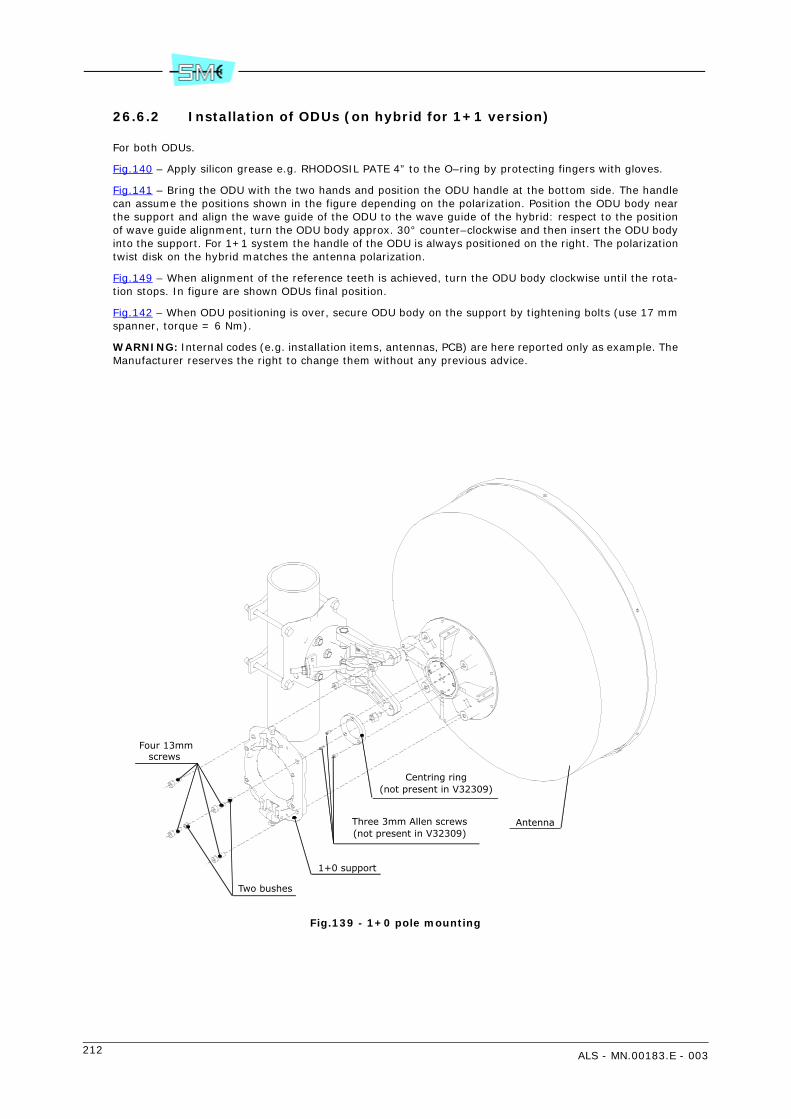
212 ALS - MN.00183.E - 003
26.6.2 Installation of ODUs (on hybrid for 1+1 version)
For both ODUs.
Fig.140 – Apply silicon grease e.g. RHODOSIL PATE 4” to the O–ring by protecting fingers with gloves.
Fig.141 – Bring the ODU with the two hands and position the ODU handle at the bottom side. The handlecan assume the positions shown in the figure depending on the polarization. Position the ODU body nearthe support and align the wave guide of the ODU to the wave guide of the hybrid: respect to the positionof wave guide alignment, turn the ODU body approx. 30° counter–clockwise and then insert the ODU bodyinto the support. For 1+1 system the handle of the ODU is always positioned on the right. The polarizationtwist disk on the hybrid matches the antenna polarization.
Fig.149 – When alignment of the reference teeth is achieved, turn the ODU body clockwise until the rota-tion stops. In figure are shown ODUs final position.
Fig.142 – When ODU positioning is over, secure ODU body on the support by tightening bolts (use 17 mmspanner, torque = 6 Nm).
WARNING: Internal codes (e.g. installation items, antennas, PCB) are here reported only as example. TheManufacturer reserves the right to change them without any previous advice.
Fig.139 - 1+0 pole mounting
Four 13mmscrews
Two bushes
1+0 support
Three 3mm Allen screws(not present in V32309)
Centring ring(not present in V32309)
Antenna
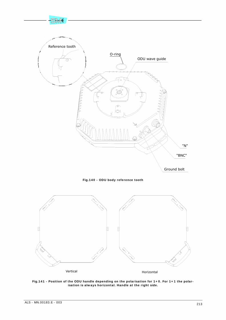
ALS - MN.00183.E - 003 213
Fig.140 - ODU body reference tooth
Fig.141 - Position of the ODU handle depending on the polarisation for 1+0. For 1+1 the polar-isation is always horizontal. Handle at the right side.
"N"
"BNC"
Ground bolt
ODU wave guide
Reference tooth
O-ring
Vertical Horizontal

214 ALS - MN.00183.E - 003
1 6 mm Allen screw
2 Bush (diagonally placed)
3 17 mm Tightening bolts (max torque = 6 Nm)
4 Reference point for horizontal polarization
5 Reference point for vertical polarization
Fig.142 - 1+0 support
1
1
2
2
3
1
1
3
4
5
4
5
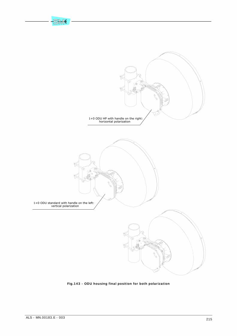
ALS - MN.00183.E - 003 215
Fig.143 - ODU housing final position for both polarization
1+0 ODU HP with handle on the right:horizontal polarization
1+0 ODU standard with handle on the left: vertical polarization

216 ALS - MN.00183.E - 003
Fig.144 - Antenna aiming
Horizontal aiming:two 17mm block screws
Vertical aiming:13mm block screws
Pole support
17mm nut for horizontaladjustment of antenna
Internal 5mm Allenscrew for vertical
adjustment of antenna
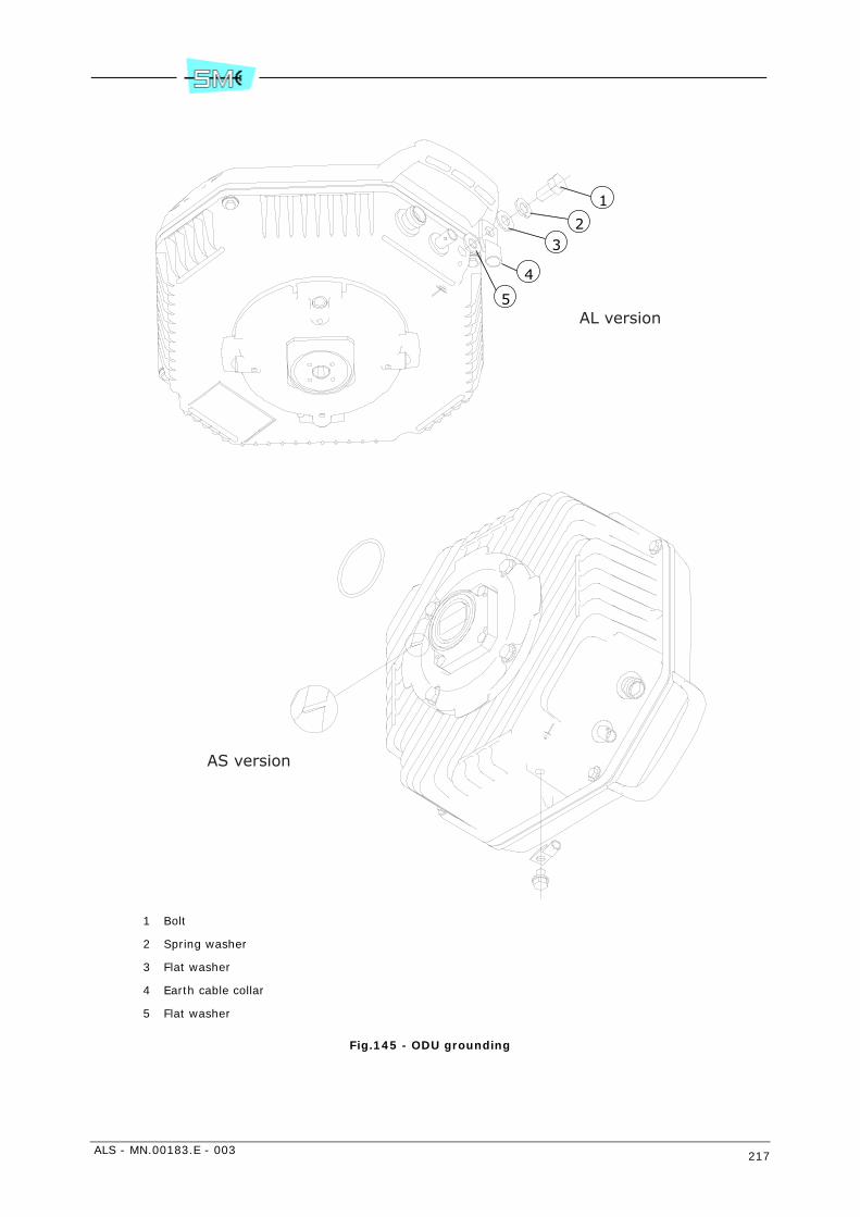
ALS - MN.00183.E - 003 217
1 Bolt
2 Spring washer
3 Flat washer
4 Earth cable collar
5 Flat washer
Fig.145 - ODU grounding
1
2
4
3
5AL version
AS version
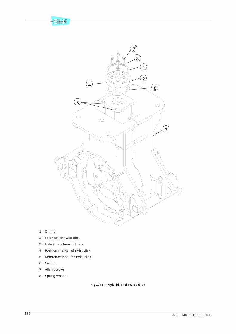
218 ALS - MN.00183.E - 003
1 O–ring
2 Polarization twist disk
3 Hybrid mechanical body
4 Position marker of twist disk
5 Reference label for twist disk
6 O–ring
7 Allen screws
8 Spring washer
Fig.146 - Hybrid and twist disk
2
1
3
4
5
6
7
8
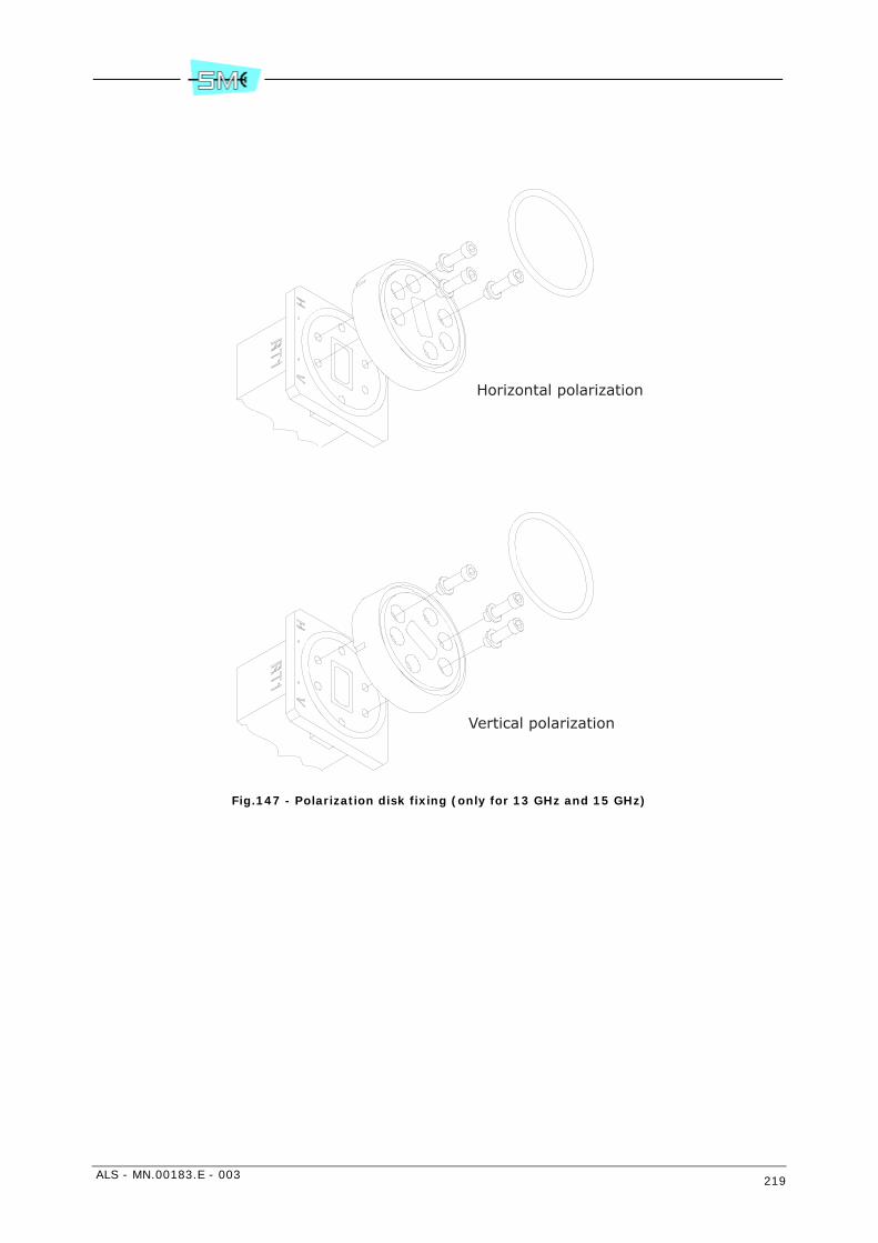
ALS - MN.00183.E - 003 219
Fig.147 - Polarization disk fixing (only for 13 GHz and 15 GHz)
Horizontal polarization
Vertical polarization
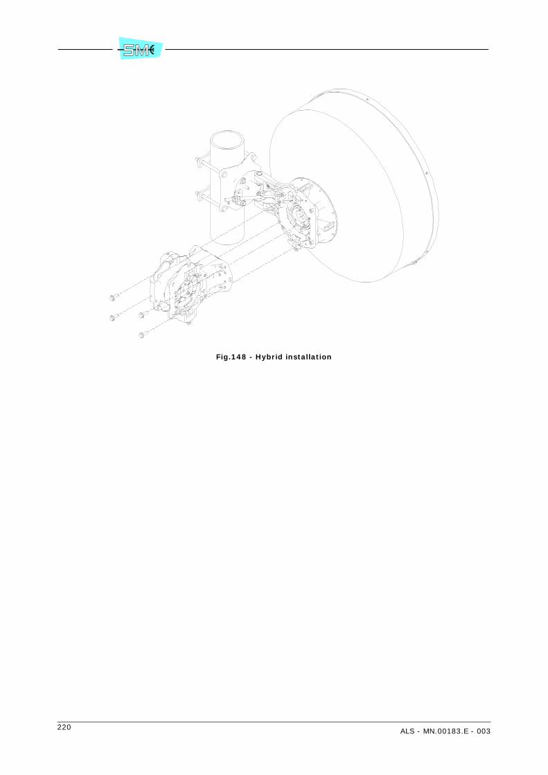
220 ALS - MN.00183.E - 003
Fig.148 - Hybrid installation
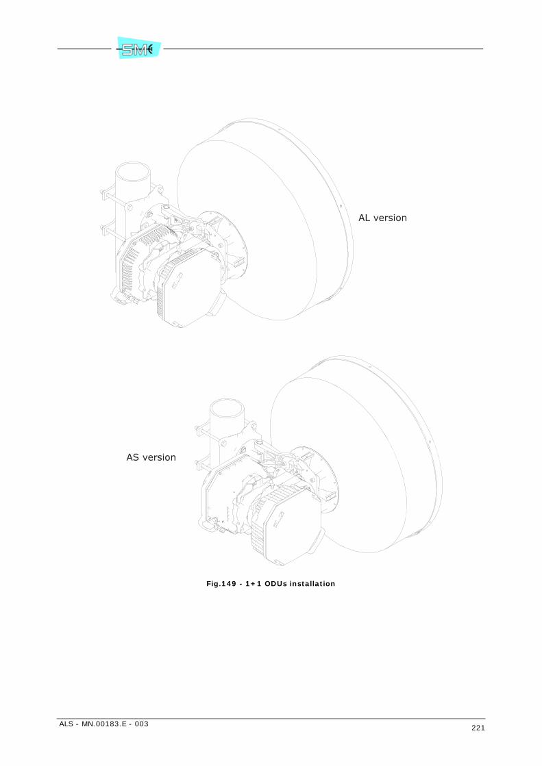
ALS - MN.00183.E - 003 221
Fig.149 - 1+1 ODUs installation
AL version
AS version

222 ALS - MN.00183.E - 003
ALS - MN.00183.E - 003 223
27 INSTALLATION ONTO THE POLE OF THE ODU WITH RFS INTEGRATED ANTENNA
27.1 FOREWORD
The installation onto the pole of the ODU with integrated antenna concerns both 1+0 and 1+1 version.
27.2 INSTALLATION KIT
Following installation kits are supplied with the equipment depending on different versions.
1+0 version
• 60 to 129 mm pole mounting kit:
- centring ring and relevant screws
- pole support system plus antenna (already assembled) and pole fixing brackets
- 1+0 ODU support and relevant screws
- ODU with O–ring and devices for ground connection
1+1 version
• 60 to 129 mm pole mounting kit:
- centring ring and relevant screws
- pole support system plus antenna (already assembled) and pole fixing brackets
- 1+0 ODU support
- hybrid and relevant screws
- polarization twist disk and relevant screws
- 2 ODUs with O–rings and devices for ground connection.
27.3 REQUIRED TOOLS FOR MOUNTING (NOT SUPPLIED)
• N.1 2.5 mm Allen wrench
• N.1 3 mm Allen wrench
• N.1 6 mm Allen wrench

224 ALS - MN.00183.E - 003
• N.1 13 mm spanner
• N.2 17 mm spanner.
Warning: if screwing operation concerns more than one screw or bolt, tighten subsequently everyone andits opposite, step by step.
27.4 INSTALLATION PROCEDURE
Installation procedure is listed below:
1+0 version
1 antenna polarization
2 installation of the centring ring on the antenna
3 installation of 1+0 ODU support
4 installation onto the pole of the assembled structure
5 installation of ODU
6 antenna aiming
7 ODU grounding
1+1 version
1 antenna polarization
2 installation of the centring ring on the antenna
3 installation of 1+0 ODU support
4 installation onto the pole of the assembled structure
5 installation of hybrid
6 installation of ODUs
7 antenna aiming
8 ODU grounding.
27.5 1+0 MOUNTING PROCEDURES
27.5.1 Setting antenna polarization
Fig.139 – Set the antenna in such a position to operate on its rear side. Locate the four M3 Allen screwsaround the antenna flange. Unscrew them (use 2.5 mm Allen wrench) and position the antenna flange ac-cording on: horizontal wave guide –> vertical polarization, vertical wave guide –> horizontal polariza-tion. Screw again the four Allen screws (torque = 1 Nm).
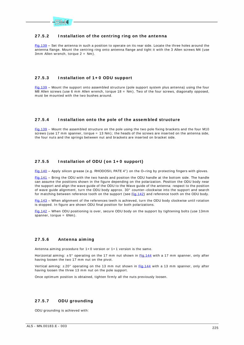
ALS - MN.00183.E - 003 225
27.5.2 Installation of the centring ring on the antenna
Fig.139 – Set the antenna in such a position to operate on its rear side. Locate the three holes around theantenna flange. Mount the centring ring onto antenna flange and tight it with the 3 Allen screws M4 (use3mm Allen wrench, torque 2 = Nm).
27.5.3 Installation of 1+0 ODU support
Fig.139 – Mount the support onto assembled structure (pole support system plus antenna) using the fourM8 Allen screws (use 6 mm Allen wrench, torque 18 = Nm). Two of the four screws, diagonally opposed,must be mounted with the two bushes around.
27.5.4 Installation onto the pole of the assembled structure
Fig.139 – Mount the assembled structure on the pole using the two pole fixing brackets and the four M10screws (use 17 mm spanner, torque = 13 Nm); the heads of the screws are inserted on the antenna side,the four nuts and the springs between nut and brackets are inserted on bracket side.
27.5.5 Installation of ODU (on 1+0 support)
Fig.140 – Apply silicon grease (e.g. RHODOSIL PATE 4”) on the O–ring by protecting fingers with gloves.
Fig.141 – Bring the ODU with the two hands and position the ODU handle at the bottom side. The handlecan assume the positions shown in the figure depending on the polarization. Position the ODU body nearthe support and align the wave guide of the ODU to the Wave guide of the antenna: respect to the positionof wave guide alignment, turn the ODU body approx. 30° counter–clockwise into the support and searchfor matching between reference tooth on the support (see Fig.142) and reference tooth on the ODU body.
Fig.143 – When alignment of the references teeth is achieved, turn the ODU body clockwise until rotationis stopped. In figure are shown ODU final position for both polarizations.
Fig.142 – When ODU positioning is over, secure ODU body on the support by tightening bolts (use 13mmspanner, torque = 6Nm).
27.5.6 Antenna aiming
Antenna aiming procedure for 1+0 version or 1+1 version is the same.
Horizontal aiming: ±5° operating on the 17 mm nut shown in Fig.144 with a 17 mm spanner, only afterhaving loosen the two 17 mm nut on the pivot.
Vertical aiming: ±20° operating on the 13 mm nut shown in Fig.144 with a 13 mm spanner, only afterhaving loosen the three 13 mm nut on the pole support.
Once optimum position is obtained, tighten firmly all the nuts previously loosen.
27.5.7 ODU grounding
ODU grounding is achieved with:
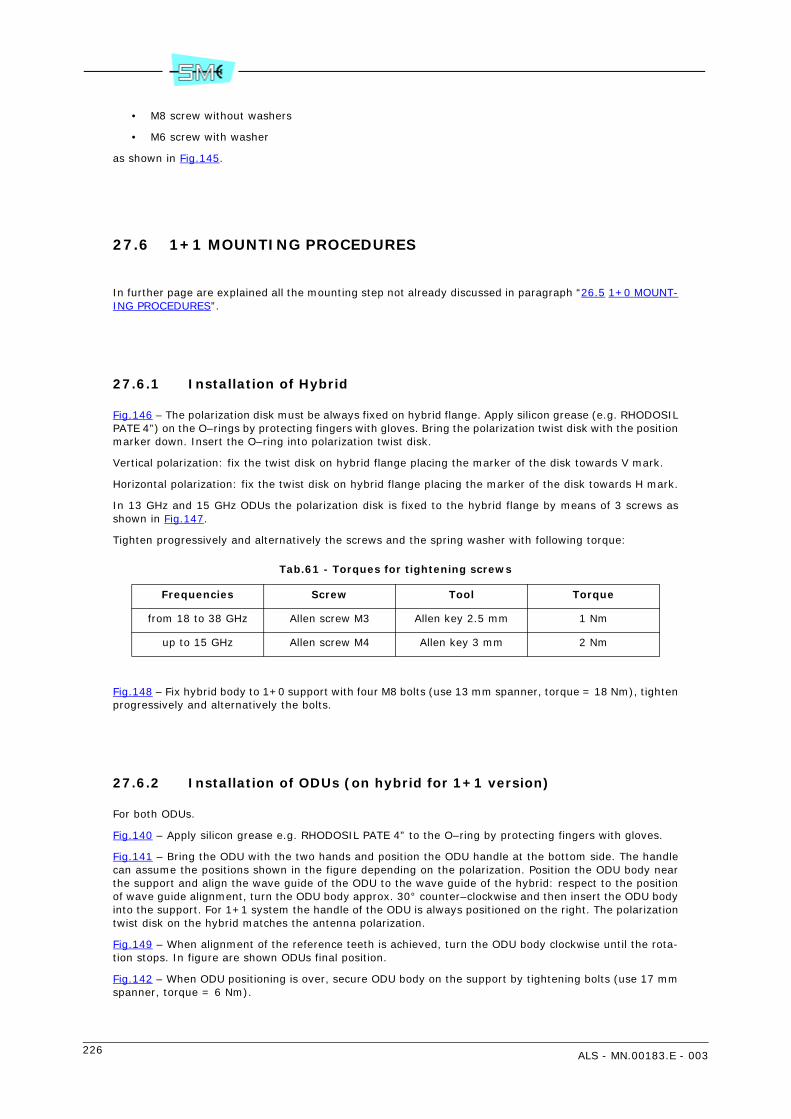
226 ALS - MN.00183.E - 003
• M8 screw without washers
• M6 screw with washer
as shown in Fig.145.
27.6 1+1 MOUNTING PROCEDURES
In further page are explained all the mounting step not already discussed in paragraph “26.5 1+0 MOUNT-ING PROCEDURES”.
27.6.1 Installation of Hybrid
Fig.146 – The polarization disk must be always fixed on hybrid flange. Apply silicon grease (e.g. RHODOSILPATE 4”) on the O–rings by protecting fingers with gloves. Bring the polarization twist disk with the positionmarker down. Insert the O–ring into polarization twist disk.
Vertical polarization: fix the twist disk on hybrid flange placing the marker of the disk towards V mark.
Horizontal polarization: fix the twist disk on hybrid flange placing the marker of the disk towards H mark.
In 13 GHz and 15 GHz ODUs the polarization disk is fixed to the hybrid flange by means of 3 screws asshown in Fig.147.
Tighten progressively and alternatively the screws and the spring washer with following torque:
Tab.61 - Torques for tightening screws
Fig.148 – Fix hybrid body to 1+0 support with four M8 bolts (use 13 mm spanner, torque = 18 Nm), tightenprogressively and alternatively the bolts.
27.6.2 Installation of ODUs (on hybrid for 1+1 version)
For both ODUs.
Fig.140 – Apply silicon grease e.g. RHODOSIL PATE 4” to the O–ring by protecting fingers with gloves.
Fig.141 – Bring the ODU with the two hands and position the ODU handle at the bottom side. The handlecan assume the positions shown in the figure depending on the polarization. Position the ODU body nearthe support and align the wave guide of the ODU to the wave guide of the hybrid: respect to the positionof wave guide alignment, turn the ODU body approx. 30° counter–clockwise and then insert the ODU bodyinto the support. For 1+1 system the handle of the ODU is always positioned on the right. The polarizationtwist disk on the hybrid matches the antenna polarization.
Fig.149 – When alignment of the reference teeth is achieved, turn the ODU body clockwise until the rota-tion stops. In figure are shown ODUs final position.
Fig.142 – When ODU positioning is over, secure ODU body on the support by tightening bolts (use 17 mmspanner, torque = 6 Nm).
Frequencies Screw Tool Torque
from 18 to 38 GHz Allen screw M3 Allen key 2.5 mm 1 Nm
up to 15 GHz Allen screw M4 Allen key 3 mm 2 Nm

ALS - MN.00183.E - 003 227
WARNING: Internal codes (e.g. installation items, antennas, PCB) are here reported only as example. TheManufacturer reserves the right to change them without any previous advice.
Fig.150 - 1+0 pole mounting
AntennaCentering ring
Three 3 mm Allen screws
1+0 support
Four 13mm screws
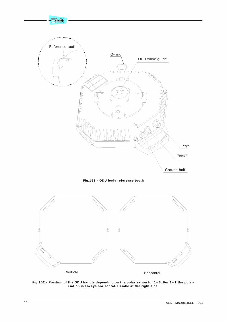
228 ALS - MN.00183.E - 003
Fig.151 - ODU body reference tooth
Fig.152 - Position of the ODU handle depending on the polarisation for 1+0. For 1+1 the polar-isation is always horizontal. Handle at the right side.
"N"
"BNC"
Ground bolt
ODU wave guide
Reference tooth
O-ring
Vertical Horizontal

ALS - MN.00183.E - 003 229
1 6 mm Allen screw M10
2 17 mm Tightening bolts (max torque = 6 Nm)
3 Reference point for horizontal polarization
4 Reference point for vertical polarization
Fig.153 - 1+0 support
1
1
2
1
1
2
3
4
3
4
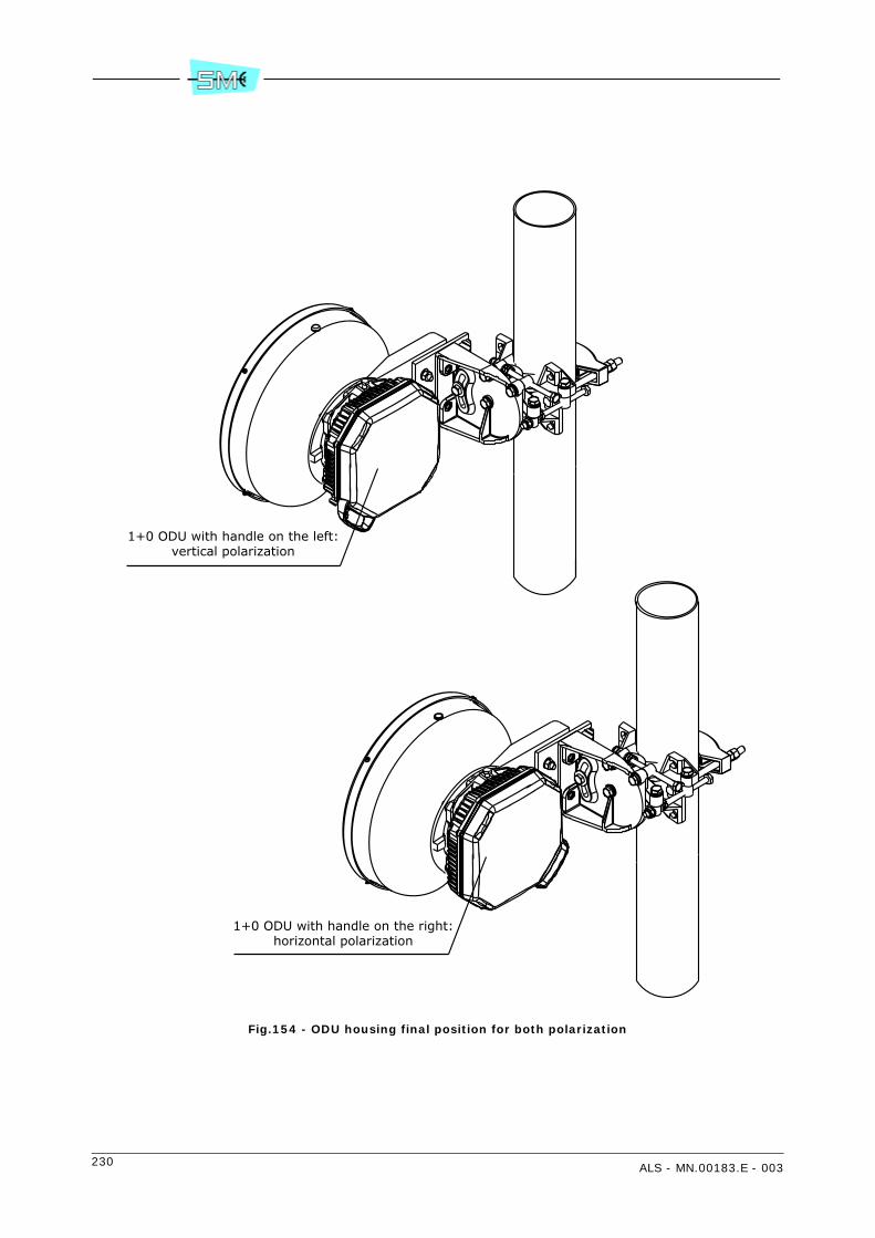
230 ALS - MN.00183.E - 003
Fig.154 - ODU housing final position for both polarization
1+0 ODU with handle on the left:vertical polarization
1+0 ODU with handle on the right:horizontal polarization
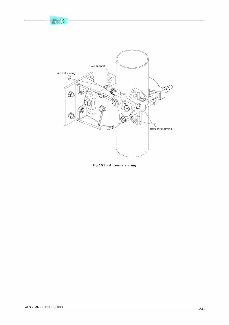
ALS - MN.00183.E - 003 231
Fig.155 - Antenna aiming
Pole support
Vertical aiming
Horizontal aiming1
2
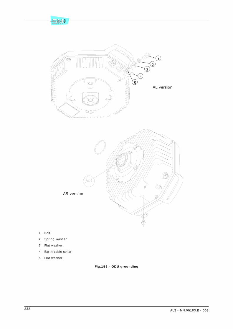
232 ALS - MN.00183.E - 003
1 Bolt
2 Spring washer
3 Flat washer
4 Earth cable collar
5 Flat washer
Fig.156 - ODU grounding
1
2
4
3
5AL version
AS version
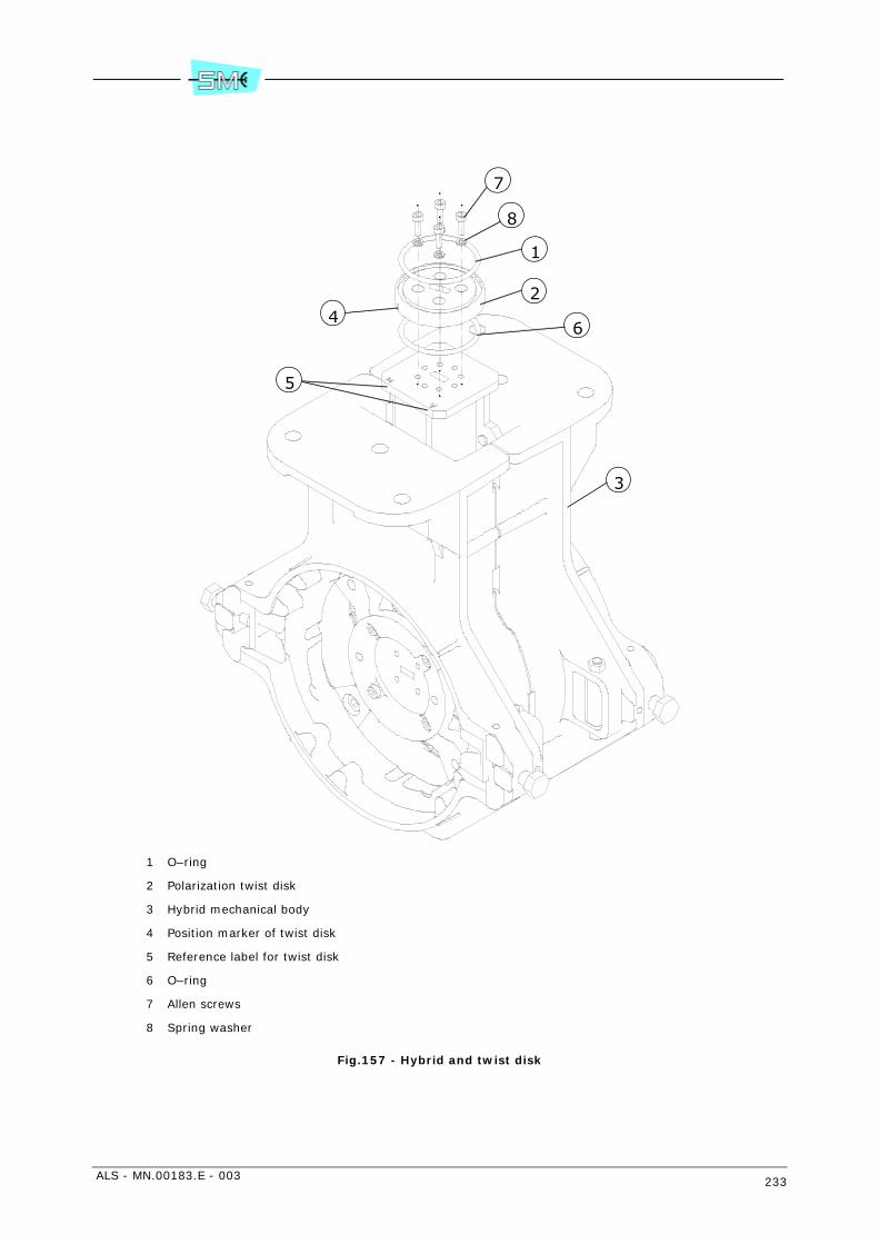
ALS - MN.00183.E - 003 233
1 O–ring
2 Polarization twist disk
3 Hybrid mechanical body
4 Position marker of twist disk
5 Reference label for twist disk
6 O–ring
7 Allen screws
8 Spring washer
Fig.157 - Hybrid and twist disk
2
1
3
4
5
6
7
8
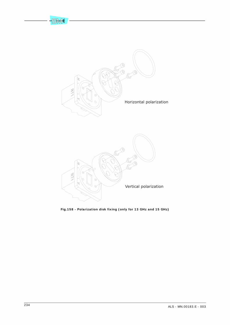
234 ALS - MN.00183.E - 003
Fig.158 - Polarization disk fixing (only for 13 GHz and 15 GHz)
Horizontal polarization
Vertical polarization
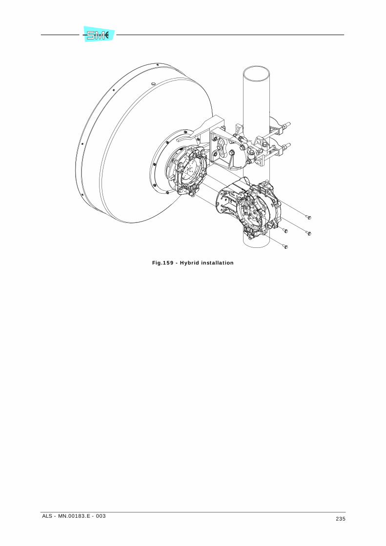
ALS - MN.00183.E - 003 235
Fig.159 - Hybrid installation
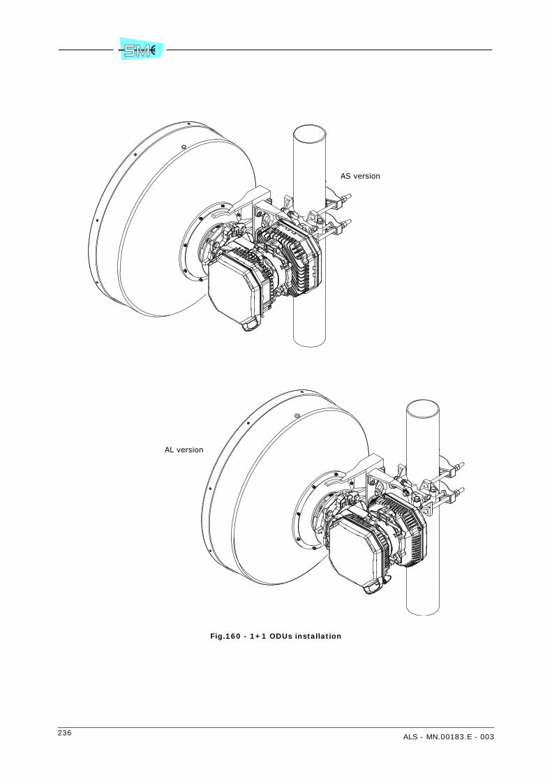
236 ALS - MN.00183.E - 003
Fig.160 - 1+1 ODUs installation
AL version
AS version

ALS - MN.00183.E - 003 237
28 INSTALLATION ONTO THE POLE OF THE 4 GHZ ODU WITH SEPARATED ANTENNA (KIT V32323)
28.1 INSTALLATION KIT
1+0 version
• anti–sliding bracket
• ODU pole support and relevant screws
1+0 version
• anti–sliding bracket
• ODU pole support and relevant screws
• hybrid and relevant screws
• hybrid–ODU connecting cables
In case of flexible wave guide use, Tab.62 shows the maximum bending radius.
28.2 REQUIRED TOOLS FOR MOUNTING (NOT SUPPLIED)
• N.2 13 mm spanner
• N.1 15 mm spanner
• N.1 17 mm spanner.
Warning: if screwing operation concerns more than one screw or bolt, tighten subsequently everyone andits opposite, step by step.
28.3 INSTALLATION PROCEDURE
Installation procedure is listed below:
• 1+0/1+1 version: pole installation of the support
• 1+1 version: installation of the hybrid on the support
• installation of the ODU on the support
• ODU grounding and connection of the cables to the hybrid and antenna

238 ALS - MN.00183.E - 003
1+0/1+1 version: pole installation of the support
Fig.161 – Install anti–sliding device (1) around the pole. The position of the plastic blocks depends on theposition of the support (2) and of the relevant hooking pin (3).
Hook the support to the plastic blocks by means of the hooking pin. Insert to the four screws (4) in therelevant holes, set the two brackets (5) and clamp them around the pole tightening the four nuts (6) (tight-ening torque = 32 Nm).
Cover the projecting bits of the screws using the relevant red covers (7).
The two holes (8) house the two tightening screws of the hybrid (only for 1+1 version).
1+1 version: hybrid installation on the support
Fig.162 – Set the hybrid (1) on the support (2) in such a way that the connectors are downward and thatthe holes on the lower side of the hybrid match with the corresponding holes (8) of the Fig.161.
Insert the two screws (3) (tightening torque = 7.3 Nm) and tighten the hybrid to the support.
ODU installation on the support
Locate the part of the support more suitable for the installation of the ODU: both the parts can be used(1+0 version).
Fig.162 – Locate the four slots (4) on the support (2).
Fig.163 – Keeping the knob of the ODU1 downward, partially screw the two screws (2) into the two upperholes of the ODU, on N connector side.
Hook the heads of the two screws (2) of the Fig.163 into the slots (4) of the Fig.162.
Insert also the remaining screws (2) into the holes (3).
Tighten all the four screws (2) (tightening torque = 7.3 Nm).
Put the sun–cover (5) over the ODU (1) and fix it to the knob of the ODU by means of the supplied strip.
In case of 1+1 version, repeat the whole procedure for the second ODU.
ODU grounding and connection of the cables to hybrid and antenna
Fig.164 – Tighten the grounding cable of each ODU by means of grounding bolt (1) (tightening torque =7.3 Nm) and the relevant washer. For the connection of the RF cable follow the label on the bottom of thehybrid: ODU1 (RT1) is that connected to RIM1 of IDU, ODU 2 (RT2) is that connected to RIM2 of IDU.
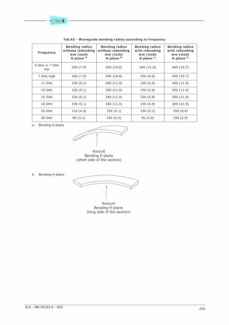
ALS - MN.00183.E - 003 239
Tab.62 - Waveguide bending radius according to frequency
Frequency
Bending radius without rebending
mm (inch)E-plane a
a. Bending E-plane
Bending radius without rebending
mm (inch)H-plane b
b. Bending H-plane
Bending radius with rebending
mm (inch)E-plane a.
Bending radius with rebending
mm (inch)H-plane b.
6 GHz or 7 GHz low
200 (7,9) 500 (19,8) 300 (11,9) 600 (23,7)
7 GHz high 200 (7,9) 500 (19,8) 250 (9,9) 600 (23,7)
11 GHz 130 (5,1) 280 (11,0) 150 (5,9) 300 (11,9)
13 GHz 130 (5,1) 280 (11,0) 150 (5,9) 300 (11,9)
15 GHz 130 (5,1) 280 (11,0) 150 (5,9) 300 (11,9)
18 GHz 130 (5,1) 280 (11,0) 150 (5,9) 300 (11,9)
23 GHz 110 (4,3) 230 (9,1) 130 (5,1) 250 (9,9)
38 GHz 80 (3,1) 140 (5,5) 90 (3,6) 150 (5,9)
Rmin/EBending E-plane
(short side of the section)
Rmin/HBending H-plane
(long side of the section)
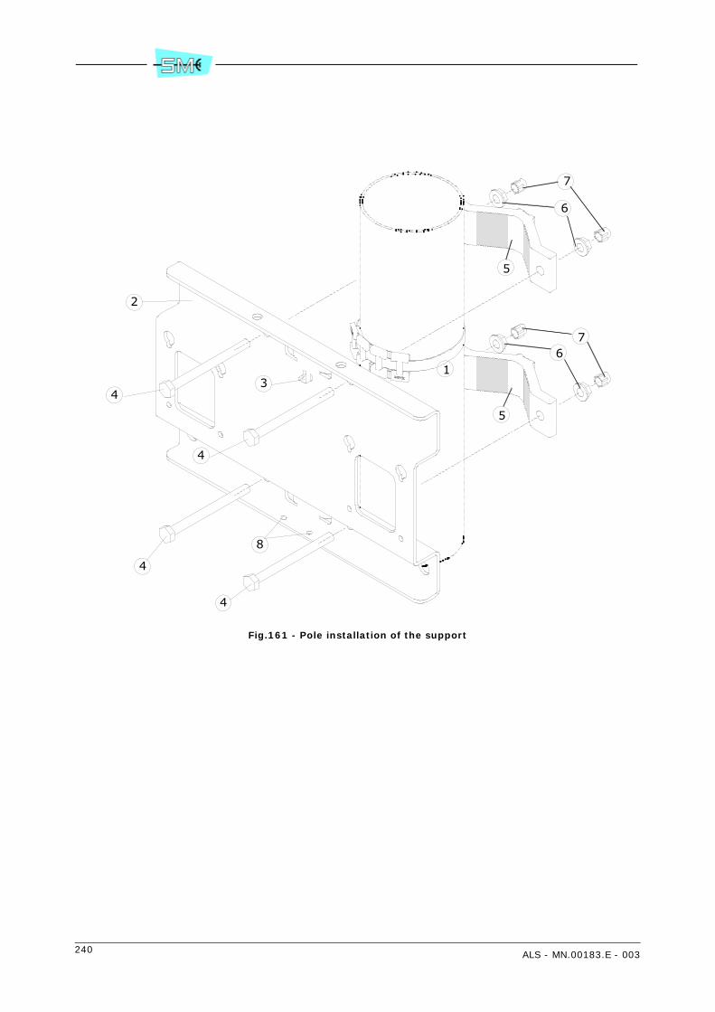
240 ALS - MN.00183.E - 003
Fig.161 - Pole installation of the support
4
4
4
4
8
2
3
6
7
67
5
5
1

ALS - MN.00183.E - 003 241
Fig.162 - Installation of the hybrid on the pole support (only for 1+1 version)
2
3
1
4
4

242 ALS - MN.00183.E - 003
Fig.163 - Installation of the ODU on the support
5
231
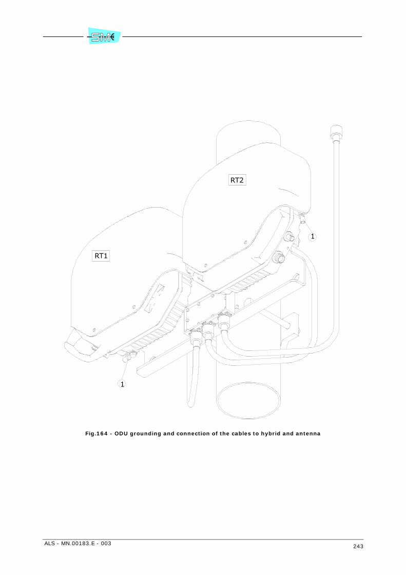
ALS - MN.00183.E - 003 243
Fig.164 - ODU grounding and connection of the cables to hybrid and antenna
1
1
RT2
RT1

244 ALS - MN.00183.E - 003
ALS - MN.00183.E - 003 245
Section 4.LINE-UP
29 LINE–UP OF THE RADIO HOP
29.1 LINE–UP OF THE RADIO HOP
The line–up consists of the following steps:
• on site radio terminal installation (user connections and ODU installation as described in the rele-vant chapters)
• equipment switch–on
• equipment configuration (through PC software)
• antenna alignment for maximum received RF signal level
• network element configuration
• check measurements.
Equipment installation is described in Section 3. INSTALLATION.
29.1.1 Equipment configuration
In order to have the link working properly, in the local and remote equipment the same parameters haveto be set:
• system layout (1+0, 1+1 hot stand-by, 1+1 frequency diversity.....) (Equipment - General)
• capacity (Equipment - General)
• modulation (Equipment - General)
• link ID (Equipment - General)
• RF channel (Radio - Radio Branch)

246 ALS - MN.00183.E - 003
The software to run is relevant to the equipment to configure:
• LCT in case of AL, ALC AL Plus
• WEB LCT in case of ALC Plus.
Traffic (Baseband - Tributary)
Used tributaries must be enabled on local and on remote equipment.
Service channels (Service Channels)
Service channels setting must be the same on local and on remote equipment: different settings of notused service channels, between local and remote equipments, cut the operation of those service channelsproperly set also.
In the following chapters, all the configuration steps are explained using LCT that differs from WEB LCT ingraphical layout only.
29.1.2 Antenna alignment and received field measurement
Purpose of antenna alignment is to maximize the RF received signal level.
Proceed as follows:
• connect a multimeter to BNC connector on the ODU for AGC measurement
• adjust antenna pointing as soon as the maximum AGC voltage value is achieved.
The relationship between AGC voltage and received field is shown by Fig.165.
The received field level has a tolerance of ±4 dB in the full temperature range.
29.1.3 Network element configuration
A factory default address is assigned to each network element that must normally be reconfigurated onsite following the network administrator rules.
To the purpose it is required to connect the PC, where the SCT/LCT program has been installed, to thenetwork interfaces.
This has to be done via serial cable or Ethernet cable.
Warning: the checks that follow require a good knowledge of the program use.
The description of each menu and relevant windows are given by the program itself as help on line.
Run the program and perform the connection to equipment by choosing from menu “Option” the connec-tion made via serial cable.
Perform the login to the equipment by entering:
• Equipment IP address 3
• User ID (default: SYSTEM)
• Password: (default: siaemicr)
Proceed to program what above mentioned following this path:
3 If the connection is made via serial cable, the IP address is automatically achieved.

ALS - MN.00183.E - 003 247
• IP Address: select menu “Equipment” from the menu bar and then Communication Setup–>PortConfiguration. Enter the required port addresses in the available communication ports. Press ? fordetails.
• Routing Table and Default Gateway: select menu “Equipment” from the menu bar and then Com-munication Setup–>Routing table: enter the routes or default gateway if necessary. Press ? for de-tails.
Warning: the routing policy depends on the routing type: manual IP/OSPF/IS–IS. The relevantrouting rules must be normally given by network administrator.
• Remote Element Table: select menu “Tools” from menu bar and then Subnetwork ConfigurationWizard. Station name and remote element table must be assigned following description of the con-textual help on–line (?).
• Agent IP Address: select menu “Equipment” and then “Properties”. Assign the address in accord-ance to the address of the remote element you want to reach.
29.1.4 Radio checks
It is advisable to perform the following measurements to check the correct operation of the radio hop:
• transmitted power
• received power
• RF frequency
• BER measurement
All these checks make use of the SCT/LCT program.
• Transmitted power, received RF level, RF frequency
- run SCT/LCT program and then perform the connection to the equipment you want to check.
- make double click on the select equipment until main RADIO PDH–AL window is shown.
- on top of the window Tx/Rx power and frequency values are displayed. In case of Tx power andfrequency setup proceed to Branch 1/2 and Power/Frequencies submenus.
• BER measurement
- Run SCT/LCT program and then perform the connection to the equipment you want to check.
- Make double click on the selected equipment until main RADIO PDH–AL window is shown.
- On the left side select BER1/2 measure.In alternative it is possible to use the PRBS function if one or 2 Mbit/s line is free.
- Perform the BER measurement and check that values comply with the requirements.
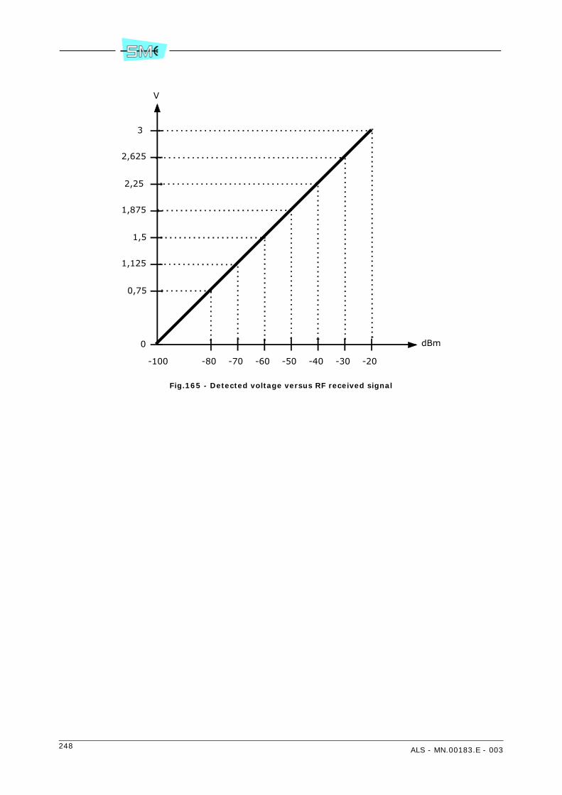
248 ALS - MN.00183.E - 003
Fig.165 - Detected voltage versus RF received signal
-100 -80 -60 -40 -20
3
2,25
1,5
0,75
0 dBm
V
-70 -50 -30
1,125
1,875
2,625

ALS - MN.00183.E - 003 249
30 LINE–UP OF LIM ETHERNET/2 MBIT/S
30.1 GENERAL
This paragraph deals with line–up of LIM Ethernet module with details of SCT/LCT program related only toEthernet application.
Assuming that the radio link is already in service, with correct frequency, output power and correct antennaalignment, the line up procedure for two different kinds of connection set up of a radio link AL, equippedwith LIM Ethernet/2 Mbit/s module, is hereafter described:
1 Local Lan–1 port to remote Lan–1 port connection Lam per port, see Fig.166
2 Local Lan–1 port to remote Lan–1 port connection with only VLANs
3 3 to 1 port connections, see Fig.179.
Settings here below are intended to be done both into local and remote radio equipment.
The software to be used depends on the equipment you have to configure.
• LCT for AL, ALC, AL Plus
• WEB LCT for ALC Plus.
In the following chapters all configuration steps are shown using LCT. LCT and WEB LCT only differs ingraphical interface.
30.2 LOCAL LAN–1 PORT TO REMOTE LAN–1 PORT TRANSPARENT CONNECTION LAN PER PORT
Settings for Untagged and Tagged Traffic
Fig.166 - Local Lan–1 port to remote Lan–1 port connection
The line–up of AL with LIM Ethernet is made with the help of SCT/LCT program.
Please refer to Fig.167. First selection is Ethernet throughput and modulation scheme, in this example weselect 16 Mbit/s and modulation 16QAM (max throughput and modulation scheme depend on terms of li-cence provided by Siae Microelettronica).
Select configuration 1+0 or 1+1 according system requirements. Inside LCT, select Tributary window (seeFig.168). If 2 Mbit/s tributaries are needed, inside the Tributary window it is possible to activate a 2 Mbit/
AL radio
port 1
switch
Lan-1
AL radio
port 1
switch
Lan-2
Lan-3
Nx2 Mbit/s
Local
Lan-1
Lan-2
Lan-3
Nx2 Mbit/s
Remote
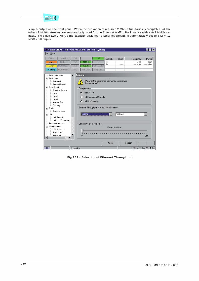
250 ALS - MN.00183.E - 003
s input/output on the front panel. When the activation of required 2 Mbit/s tributaries is completed, all theothers 2 Mbit/s streams are automatically used for the Ethernet traffic. For instance with a 8x2 Mbit/s ca-pacity if we use two 2 Mbit/s the capacity assigned to Ethernet circuits is automatically set to 6x2 = 12Mbit/s full duplex.
Fig.167 - Selection of Ethernet Throughput

ALS - MN.00183.E - 003 251
Fig.168 - Tributary enable
See Fig.169 for General settings for the switch. All the used ports must be Enabled, so enable Lan–1 andInternal Port, see Fig.170.
The other ports should be disabled. The correct cable crossover arrangement must be selected too (seeFig.170). Enable LLF if needed only at the end of link line up.
For Untagged traffic, connections are done with Lan per port selections. Referring to Fig.171 incoming traf-fic at Lan–1 exits at Internal Port and into Fig.173 incoming traffic at Internal Port exits at lan–1 port. Thisconnection are done for all Untagged traffic and all Tagged packets with Vlan Id not described into VlanConfiguration Table.
If Vlan Configuration Table is blank all Tagged traffic follows the rules of Lan per port.
Possible selections of Ingress Filtering Check:
1 “Disable 802.1q”: no check of Virtual Lan tag is made and all packets follow Lan per port settings
2 “Fallback”: if Tagged packets have their Vlan Id into Vlan Configuration Table they follow the con-nection described into the table, otherwise they follow the Lan per port settings as Untagged pack-ets
3 “Secure”: no Untagged packet transits; only Tagged packets with Vlan Id listed into the table cantransit. For all pass configuration “Disable 802.1” should be selected. With Egress Mode as Unmodi-fied the outgoing packets at Lan–1 port exit Untagged or Tagged exactly as they were Untagged orTagged at the incoming port.

252 ALS - MN.00183.E - 003
Fig.169 - Switch general settings
Fig.170 - Lan–1 interface settings
Link Loss Forwarding Histeresys
Click here for Port mapping andVLAN configuration table
Output policyfor Taggedpackets: Level2 priority, ifused, definedfor all the portsfor incomingpacketsalready Tagged

ALS - MN.00183.E - 003 253
Fig.171 - Vlan settings for Lan–1
Fig.172 - Priority setting for Lan–1 and Internal Port
With Priority disabled no check is done into 802.1p priority Tag. All types of packets go into Default PriorityQueue.
InvomingUntaggedpackets at
Lan-1 are sent into output partqueue followingthis selection.
In this examplepackets areinserted into
queue 0
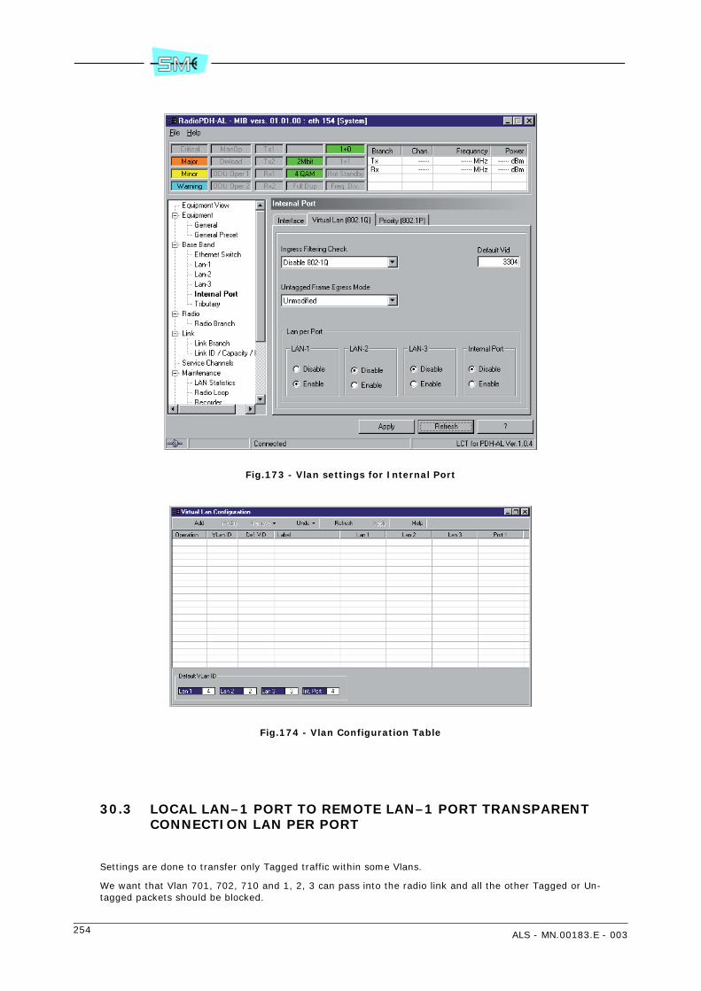
254 ALS - MN.00183.E - 003
Fig.173 - Vlan settings for Internal Port
Fig.174 - Vlan Configuration Table
30.3 LOCAL LAN–1 PORT TO REMOTE LAN–1 PORT TRANSPARENT CONNECTION LAN PER PORT
Settings are done to transfer only Tagged traffic within some Vlans.
We want that Vlan 701, 702, 710 and 1, 2, 3 can pass into the radio link and all the other Tagged or Un-tagged packets should be blocked.

ALS - MN.00183.E - 003 255
The line up of AL with LIM Ethernet is made with the help of LCT/SCT program. Please refer to Fig.166.First selection is Ethernet throughput and modulation scheme, in this example we select 16 Mbit/s andmodulation 16QAM (max throughput and modulation scheme depends on terms of licence provided by SiaeMicroelettronica). Select configuration 1+0 or 1+1 according system requirements.
Inside LCT, select tributary window (see Fig.167). If 2 Mbit/s tributaries are needed, inside the tributarywindow it is possible to activate a 2 Mbit/s input/output on the front panel. When the activation of required2 Mbit/s tributaries is completed, all the others 2 Mbit/s streams are automatically used for the Ethernettraffic. for instance with a 16 Mbit/s capacity if we use two 2 Mbit/s the capacity assigned to ethernet cir-cuits is automatically set to 16–2x2 = 12 Mbit/s full duplex.
See Fig.168 for general settings for the switch. All the used ports must be enabled, so enable Lan–1 andInternal Port, see Fig.169. The other port should be disabled. The correct Cable crossover arrangementmust be selected too. Enable LLF if needed only at the end of link line up.
Vlan settings for Lan–1 and Internal Port should be like in Fig.175 with Ingress Filtering Check as “Secure”and Engress Mode as “Tagged”. With this setting only Tagged packets with Vlan ID listed into the Vlan Con-figuration Table can transit. All Untagged packets are blocked at the incoming port and outgoing Taggedpackets don’t change.
A packet with Vlan ID XX can enter into the switch only if Incoming Port (Ingress port) is a member of theVlan XX, same packet will exit only from ports (Engress Port) which are members of Vlan XX. Vlan mem-bership is described into Vlan Configuration Table. A port can be member of no one, one or more Vlans.See Fig.176 for Vlan Configuration Table settings for our example.
Fig.175 - Virtual Lan input and output settings at Lan–1 port

256 ALS - MN.00183.E - 003
Fig.176 - Vlan Configuration Table with some Vlans
Tagged incoming packet can be treated with FIFO policy or on the basis of their 802.1p priority tag andToS/DSCP value for IP packets. There are 4 queue at each output port. The decision about to which outputqueue to send a packet is defined into Ethernet switch window selections for 802.1p tag. Into Ethernetswitch window it is possible to select ToS/DSCP button to open window ToS/DSCP, in this window eachincoming ToS/DSCP value is associated with an output queue so it is possible to change the priority of theincoming packet.
When no info on priority is available, the packet is sent to Default Priority Queue using FIFO policy.
Into Lan–1 window select Priority (802.1q), into priority box there are some selections: with “Disable”switch doesn’t look at priority tag; with “802.1p” switch looks at Tag 802.1p only; with “IpToS” for IP pack-ets only switch looks to ToS/DSCP identifier (into IP frame) only; with “802.1p – IpToS” switch looks firstto 802.1p tag and secondly to ToS/DSCP, see Fig.178; with “IpToS–802.1p” switch looks first to ToS/DSCPand secondly to Tag 802.1p.
Note: with IpToS switch looks to IP packet and ToS/DSCP doesn’t matter if the packets are tagged with802.1p or not.
In this example incoming tagged are tagged and it is necessary to transfer the packets with no change sothey must exit from output ports tagged, see Fig.176 and Fig.177.
Fig.177 - Add a new Vlan ID to Vlan Configuration Table with output tagged

ALS - MN.00183.E - 003 257
Fig.178 - Layer 2 and Layer 3 priority management
30.4 3 TO 1 PORT CONNECTIONS
Fig.179 - 3 to 1 port connections
In this example 3 local port must communicate with corresponding remote ports. All the ports share thesame radio channel but traffic originated and directed to Lan1 should be kept separated from traffic fromLan2 and Lan3 and viceversa.
Lan–1 to Lan–1 connection should transfer tagged packets with Vlan 1, 701, 760 and untagged packets.Unspecified tagged packets must be stopped. Lan–2 and Lan–3 have the same requirements. For all con-nections IP packets with high priority TOS should transferred at minimum delay.
IncomingUntaggedpackets at
Lan-1 are sentinto output partqueue followingthis selection.
In this examplepackets areinserted into
queue 0.
AL radio
port 1
switch
Lan-1
AL radio
port 1
switch
Lan-2
Lan-3
Nx2 Mbit/s
Local
Lan-1
Lan-2
Lan-3
Nx2 Mbit/s
Remote
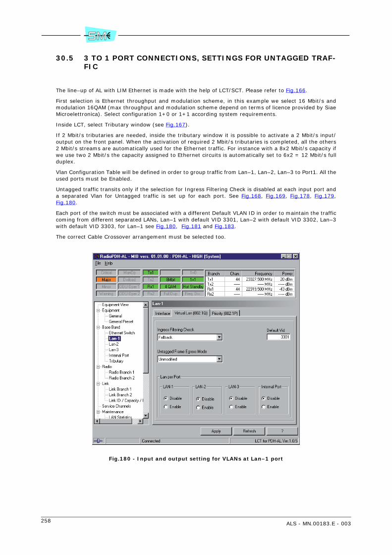
258 ALS - MN.00183.E - 003
30.5 3 TO 1 PORT CONNECTIONS, SETTINGS FOR UNTAGGED TRAF-FIC
The line–up of AL with LIM Ethernet is made with the help of LCT/SCT. Please refer to Fig.166.
First selection is Ethernet throughput and modulation scheme, in this example we select 16 Mbit/s andmodulation 16QAM (max throughput and modulation scheme depend on terms of licence provided by SiaeMicroelettronica). Select configuration 1+0 or 1+1 according system requirements.
Inside LCT, select Tributary window (see Fig.167).
If 2 Mbit/s tributaries are needed, inside the tributary window it is possible to activate a 2 Mbit/s input/output on the front panel. When the activation of required 2 Mbit/s tributaries is completed, all the others2 Mbit/s streams are automatically used for the Ethernet traffic. For instance with a 8x2 Mbit/s capacity ifwe use two 2 Mbit/s the capacity assigned to Ethernet circuits is automatically set to 6x2 = 12 Mbit/s fullduplex.
Vlan Configuration Table will be defined in order to group traffic from Lan–1, Lan–2, Lan–3 to Port1. All theused ports must be Enabled.
Untagged traffic transits only if the selection for Ingress Filtering Check is disabled at each input port anda separated Vlan for Untagged traffic is set up for each port. See Fig.168, Fig.169, Fig.178, Fig.179,Fig.180.
Each port of the switch must be associated with a different Default VLAN ID in order to maintain the trafficcoming from different separated LANs, Lan–1 with default VID 3301, Lan–2 with default VID 3302, Lan–3with default VID 3303, for Lan–1 see Fig.180, Fig.181 and Fig.183.
The correct Cable Crossover arrangement must be selected too.
Fig.180 - Input and output setting for VLANs at Lan–1 port
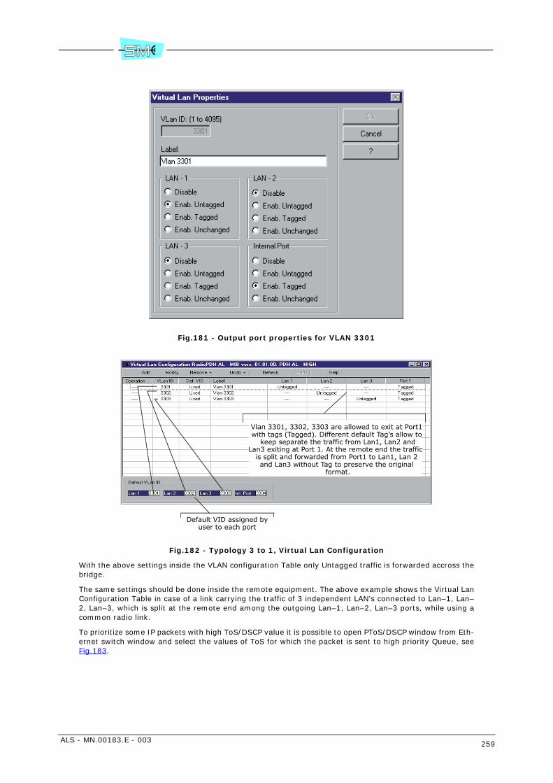
ALS - MN.00183.E - 003 259
Fig.181 - Output port properties for VLAN 3301
Fig.182 - Typology 3 to 1, Virtual Lan Configuration
With the above settings inside the VLAN configuration Table only Untagged traffic is forwarded accross thebridge.
The same settings should be done inside the remote equipment. The above example shows the Virtual LanConfiguration Table in case of a link carrying the traffic of 3 independent LAN’s connected to Lan–1, Lan–2, Lan–3, which is split at the remote end among the outgoing Lan–1, Lan–2, Lan–3 ports, while using acommon radio link.
To prioritize some IP packets with high ToS/DSCP value it is possible to open PToS/DSCP window from Eth-ernet switch window and select the values of ToS for which the packet is sent to high priority Queue, seeFig.183.
Default VID assigned byuser to each port
Vlan 3301, 3302, 3303 are allowed to exit at Port1 with tags (Tagged). Different default Tag’s allow to
keep separate the traffic from Lan1, Lan2 andLan3 exiting at Port 1. At the remote end the traffic
is split and forwarded from Port1 to Lan1, Lan 2 and Lan3 without Tag to preserve the original
format.

260 ALS - MN.00183.E - 003
Fig.183 - Output Queue selection on the basis of TOS/DSCP priority
30.6 3 TO 1 PORT CONNECTIONS, SETTINGS FOR TAGGED AND UN-TAGGED TRAFFIC
If we want VLAN with Tag 701, 702 and 703 to transit between Lan–1 and Port–1 it is necessary to definePort 1 and Lan 1 as members of VLAN1, 701, 760 (see Fig.184 for VLAN 701 and do the same for VLAN1,760).
The VLAN Configuration Table will look like Fig.185.
For Lan–2 and Lan–3 we cannot use the same Vlan if we want to maintain traffic from Lan 1, 2, 3 separated.We must change the number of incoming Vlan for instance of 1, 701, 760 use 2001, 2701, 2760 for Lan–2 and 3001, 3701, 3760 for Lan–3. Connected equipment to Lan–2 port should be reprogrammed to useVlan 2001, 2701, 2760.
Connected equipment to Lan–3 port should be reprogrammed to use Vlan 3001, 3701, 3760.
To prioritize Ip packets with high ToS/DSCP value it is possible to open PToS/DSCP window from Ethernetswitch window and select the values of ToS for which the packet is sent to high priority Queue 3, seeFig.181. The same should be done inside the remote equipment.
TOS value description DSCP value description
Packets with AF43prioritylevel willgo into
Queue 3 atall ports
AF43 now goes to Queue 3, with this button AF43 will go to Queue 2

ALS - MN.00183.E - 003 261
Fig.184 - Output properties of VLAN 701
Fig.185 - Typology 3 to 1, Virtual Lan Configuration Table with Vlan
30.7 3 TO 1 CONNECTIONS: EXAMPLES OF PRIORITY MANAGEMENT
Example 1: To assign to Lan–1 and Lan–3 low priority and to Lan–2 high priority, while wanting Taggedand Untagged to be treated in a fair manner on each queue do as follow: select Priority Disable for Lan–1,Lan–2 and Lan–3; select Default Priority Queue equal to Queue 0 for lan–1 and Lan–3 (see Fig.172). SelectDefault Priority Queue equal to Queue 3 for Lan–2 (as in Fig.186).
Outgoing Untagged packets will take priority tag defined into input port, in this case 0. Tagged frames keeptheir tag.
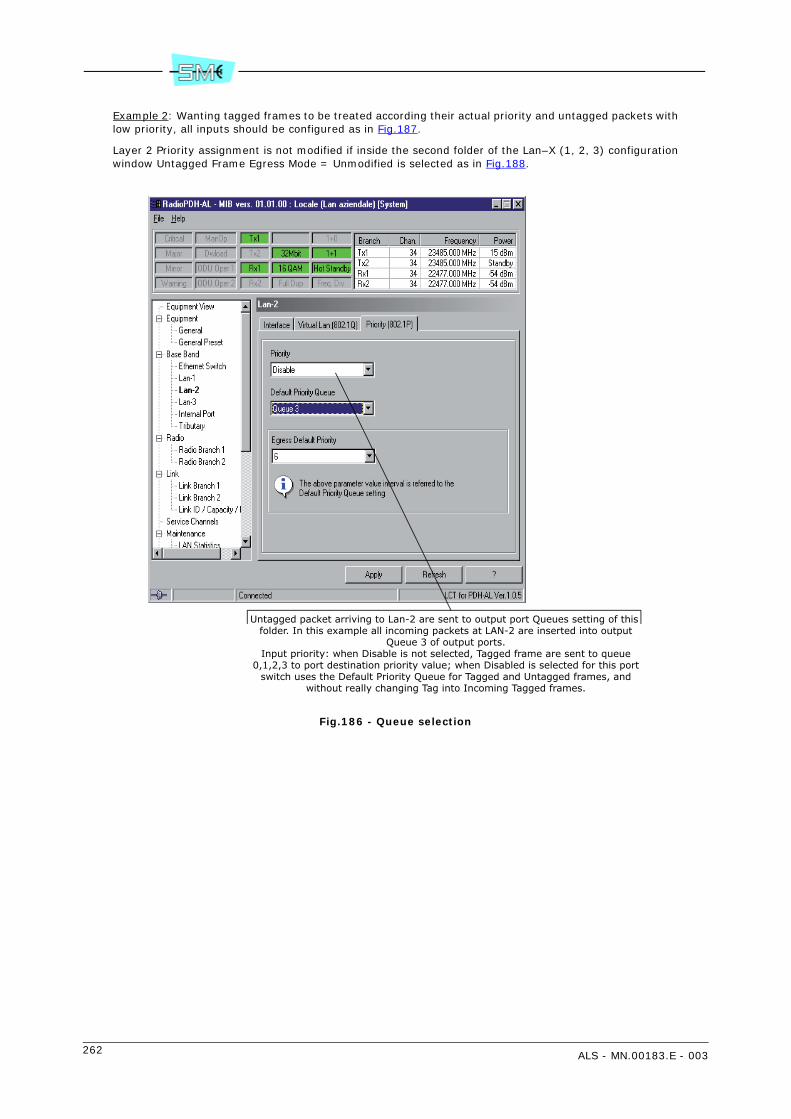
262 ALS - MN.00183.E - 003
Example 2: Wanting tagged frames to be treated according their actual priority and untagged packets withlow priority, all inputs should be configured as in Fig.187.
Layer 2 Priority assignment is not modified if inside the second folder of the Lan–X (1, 2, 3) configurationwindow Untagged Frame Egress Mode = Unmodified is selected as in Fig.188.
Fig.186 - Queue selection
Untagged packet arriving to Lan-2 are sent to output port Queues setting of this folder. In this example all incoming packets at LAN-2 are inserted into output
Queue 3 of output ports.Input priority: when Disable is not selected, Tagged frame are sent to queue
0,1,2,3 to port destination priority value; when Disabled is selected for this portswitch uses the Default Priority Queue for Tagged and Untagged frames, and
without really changing Tag into Incoming Tagged frames.

ALS - MN.00183.E - 003 263
Fig.187 - Management of tagged frames according with their priority tag
Fig.188 - Incoming packets at Lan–1 will exit to other ports unchanged according their incom-ing status.
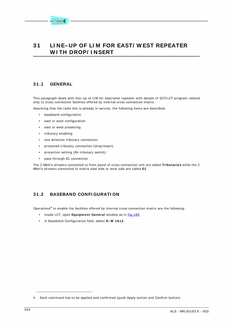
264 ALS - MN.00183.E - 003
31 LINE–UP OF LIM FOR EAST/WEST REPEATER WITH DROP/INSERT
31.1 GENERAL
This paragraph deals with line–up of LIM for east/west repeater with details of SCT/LCT program relatedonly to cross connection facilities offered by internal cross connection matrix.
Assuming that the radio link is already in service, the following items are described:
• baseband configuration
• east or west configuration
• east or west presetting
• tributary enabling
• one direction tributary connection
• protected tributary connection (drop/insert)
• protection setting (Rx tributary switch).
• pass through E1 connection
The 2 Mbit/s streams connected to front panel of cross connection unit are called Tributaries while the 2Mbit/s streams connected to matrix east side or west side are called E1.
31.2 BASEBAND CONFIGURATION
Operations4 to enable the facilities offered by internal cross connection matrix are the following:
• inside LCT, open Equipment General window as in Fig.189.
• in Baseband Configuration field, select E–W 16x2.
4 Each command has to be applied and confirmed (push Apply button and Confirm button)

ALS - MN.00183.E - 003 265
Fig.189 - Baseband configuration
31.3 EAST/WEST CONFIGURATION
Operations to configure the radio link toward one direction are the following:
• inside LCT, open Equipment General East (or West) window as in Fig.190
• select proper parameters in Capacity&Modulation Scheme field and right Link ID in Local Link IDfield (0 means “not used”).
Configuration of one direction can be different respect the other: if different capacities are selected,number of pass–through connection depend on this.

266 ALS - MN.00183.E - 003
Fig.190 - Configuration of radio branch of one direction
31.4 EAST OR WEST PRESETTING
In case of bad quality of Rx signal from one direction, HBER on east or west branch, some features can beenabled: inside LCT as in Fig.191, open Equipment, open Gen. Preset East (or West) and:
• in order to insert AIS in case of HBER: select Enable in Hber –> Rx Ais Ins Rx Sw field
• in order to insert AIS in case of hardware failure in Rx: select Enable in Ais Rx Insertion field
• in order to cut the signal of service channels in case of HBER: select Enable in Service Squelch field

ALS - MN.00183.E - 003 267
Fig.191 - Presetting of radio branch of one direction
31.5 TRIBUTARY ENABLING
In order to enable/disable the tributaries connected to the cross–connection unit, inside LCT as in Fig.192,open Base Band, open Tributary and click on central square of each tributary:
• central line open: the tributary is disabled
• central line closed: the tributary is enabled.
If the rectangle with a little black triangle is clicked, four alarms relevant the tributary appear: AIS, BER(BER = 10–6), OOF (Out Of Frame), OOMF (Out of MultiFrame).
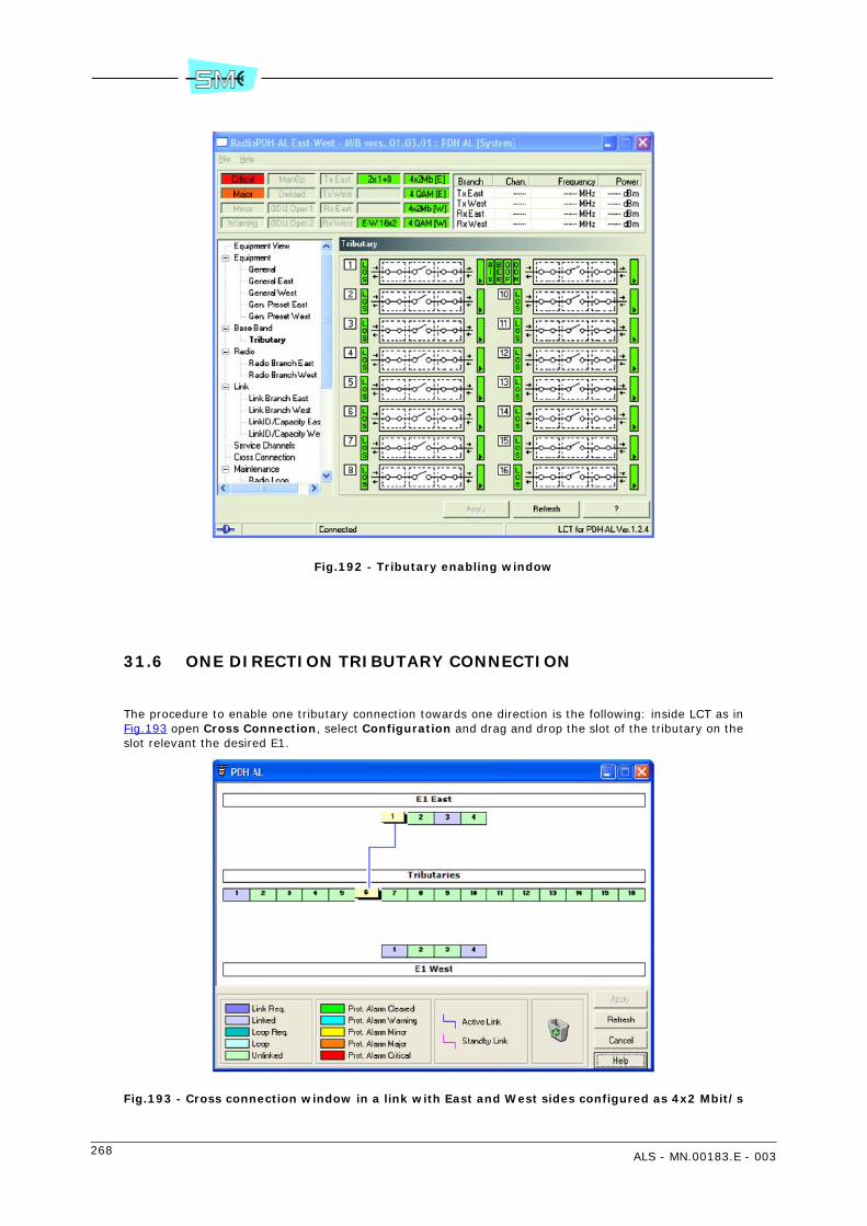
268 ALS - MN.00183.E - 003
Fig.192 - Tributary enabling window
31.6 ONE DIRECTION TRIBUTARY CONNECTION
The procedure to enable one tributary connection towards one direction is the following: inside LCT as inFig.193 open Cross Connection, select Configuration and drag and drop the slot of the tributary on theslot relevant the desired E1.
Fig.193 - Cross connection window in a link with East and West sides configured as 4x2 Mbit/s
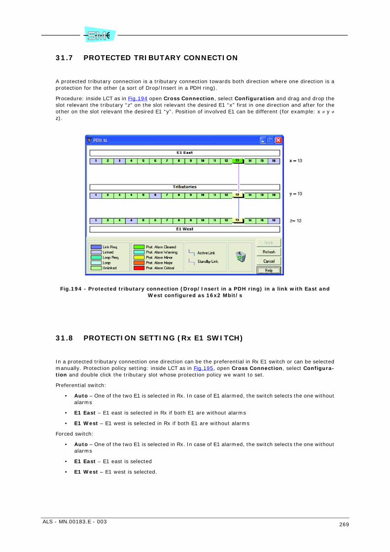
ALS - MN.00183.E - 003 269
31.7 PROTECTED TRIBUTARY CONNECTION
A protected tributary connection is a tributary connection towards both direction where one direction is aprotection for the other (a sort of Drop/Insert in a PDH ring).
Procedure: inside LCT as in Fig.194 open Cross Connection, select Configuration and drag and drop theslot relevant the tributary “z“ on the slot relevant the desired E1 “x” first in one direction and after for theother on the slot relevant the desired E1 “y”. Position of involved E1 can be different (for example: x ≠ y ≠z).
Fig.194 - Protected tributary connection (Drop/Insert in a PDH ring) in a link with East and West configured as 16x2 Mbit/s
31.8 PROTECTION SETTING (Rx E1 SWITCH)
In a protected tributary connection one direction can be the preferential in Rx E1 switch or can be selectedmanually. Protection policy setting: inside LCT as in Fig.195, open Cross Connection, select Configura-tion and double click the tributary slot whose protection policy we want to set.
Preferential switch:
• Auto – One of the two E1 is selected in Rx. In case of E1 alarmed, the switch selects the one withoutalarms
• E1 East – E1 east is selected in Rx if both E1 are without alarms
• E1 West – E1 west is selected in Rx if both E1 are without alarms
Forced switch:
• Auto – One of the two E1 is selected in Rx. In case of E1 alarmed, the switch selects the one withoutalarms
• E1 East – E1 east is selected
• E1 West – E1 west is selected.

270 ALS - MN.00183.E - 003
Fig.195 - Protection policy of a tributary stream
31.9 PASS–THROUGH E1 CONNECTION
A pass–through E1 connection is a connection between one East E1 stream and one West E1 stream.
How to set a Pass–through E1 connection: inside LCT as in Fig.196, open Cross Connection, select Con-figuration and drag and drop the slot relevant the East E1 on the slot relevant the West E1. East and WestE1 can be different.
Fig.196 - East/West Pass–through connection in a link with East and West configured as 16x2 Mbit/s

ALS - MN.00183.E - 003 271
32 LINE-UP OF THE LINK WITH NODAL IDU
32.1 OVERVIEW
The following paragraph deals with the activation of the NODAL IDU unit with details of the SCT/LCT pro-gram relevant to the functionalities offered by the cross-connection matrix in relation to the achievableconnections.
Supposing that the radio links are already commissioned, the following items are described:
• Tributaries on line side and tributaries on radio side
• Tributaries on line side and other tributaries on line side (protected and unprotected buses included)
• Tributaries on radio side and other tributaries on radio side
32.2 EQUIPMENT CONFIGURATION
The operations to enable the functionalities offered by the internal cross-connection matrix are the follow-ing:
1 run the software LCT, open Equipment, Configurator as in Fig.197
2 configure the IDU as 2U, Drop Insert, Matrix (with relevant tributaries)
3 configure the radio links: Radio A (1A and 2A, with 2x(1+0)) and Radio B (1B and 2B, with 2x(1+0))
4 configure the LIM: Processor
5 define the IDU you are configuring: No Nodal (single nodal IDU), Node A, Node B, Node C
6 configure the node type: 2 Elems, 3 Elems
7 configure the type of BUS connecting the IDUs: No Protec. (NBUS 1 and 2 -> transport of 126 E1each), Protec. (single NBUS-> transport of 126 E1)
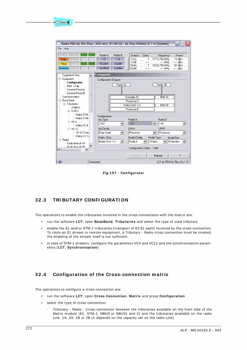
272 ALS - MN.00183.E - 003
Fig.197 - Configurator
32.3 TRIBUTARY CONFIGURATION
The operations to enable the tributaries involved in the cross-connections with the matrix are:
• run the software LCT, open BaseBand, Tributaries and select the type of used tributary
• enable the E1 and/or STM-1 tributaries (transport of 63 E1 each) involved by the cross-connection.To route an E1 stream to remote equipment, a Tributary - Radio cross-connection must be created,the enabling of the stream itself is not sufficient.
• in case of STM-1 streams, configure the parameters VC4 and VC12 and the synchronization param-eters (LCT, Synchronisation)
32.4 Configuration of the Cross-connection matrix
The operations to configure a cross-connection are:
• run the software LCT, open Cross Connection, Matrix and press Configuration
• select the type of cross-connection:
- Tributary - Radio : Cross-connection between the tributaries available on the front side of theMatrix module (E1, STM-1, NBUS or NBUS1 and 2) and the tributaries available on the radioLink, 1A, 2A, 1B or 2B (it depends on the capacity set on the radio Link)

ALS - MN.00183.E - 003 273
- Tributary - Tributary : Cross-connection between the tributaries available on the front side ofthe Matrix module (E1, STM-1, NBUS or NBUS1 and 2)
32.4.1 Tributary - Radio Cross-connection
The operations to create and configure this cross-connection are:
• select the type of tributary to use on the front side of the Matrix module: the relevant E1 streamswill be displayed in the window together with the number of E1 streams relevant to the radio Link
• select which radio Link you wish to use in the cross-connection (up to four available)
• move the symbol of the E1 stream (the number corresponds to the physical position in the connec-tor of the Matrix module) by dragging and dropping from a type of tributary to the position to usein the radio frame, see Fig.198.
• the first create cross-connection is the main (colour blue); a second one regarding the same E1 trib-utary can be created to the radio Link B with the same modality. The second cross-connection willbe the reserve (colour pink) of the first one. The parameters, and the possible alarms, ruling theswitch between the two radio directions can be configured in the window which can be opened bya double click on the box relevant to the E1 tributary on matrix side, see Fig.199
• the tributaries in the radio frame (Link direction A or others) can be involved in a tributary looptowards the corresponding remote radio by means of a double click on the relevant box that pointsout the position in the frame, see Fig.200
• the tributaries on radio side can transit directly from a radio link to the other without need to passfrom the tributaries on matrix side: by means of drag'n'drop, a box relevant to an E1 on radio sideis moved from a Link to the other Link. The two involved Links must be selected in the fields 1stRadio and 2nd Radio. A pass-through (transit) cross-connection is so executed: see Fig.201
• to delete a cross-connection, move it to the trash
• to activate the configuration, press Apply and Confirm.
Fig.198 - Radio/Tributary

274 ALS - MN.00183.E - 003
Fig.199 - Switch parameters of the cross-connections
Fig.200 - Tributary loop on radio side

ALS - MN.00183.E - 003 275
Fig.201 - Radio/radio cross-connection
32.4.2 Tributary - Tributary Cross-connection
The operations to create and configure this cross-connection are:
1 select the two types of tributary (1st Tributary and 2nd Tributary) on the front side of the Matrixmodule to use as ends: the relevant E1 streams will be displayed in the top and bottom part of thewindow
2 move the symbol of the E1 stream (the number corresponds to the physical position in the connec-tor on the Matrix module) by means of the drag'n'drop from a tributary type to another, see Fig.202.
3 to delete a cross-connection, move to the trash
4 to activate the configuration, press Apply and Confirm.
This type of cross-connection includes even those relevant to the transport of E1 streams from a nodal IDUto another one belonging to the same node.
Remember that, in case of protected NBUS connections, there is not distinction between NBUS1 and 2,while the single generic NBUS connection will be displayed.
The configuration of the transport of E1 streams from a nodal IDU to another one belonging to the samenode must be executed on both the involved nodal IDUs.

276 ALS - MN.00183.E - 003
Fig.202 - Tributary/Tributary Cross-connection
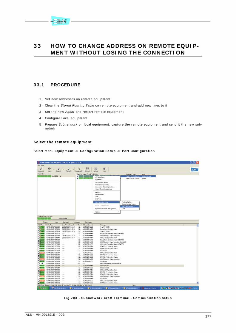
ALS - MN.00183.E - 003 277
33 HOW TO CHANGE ADDRESS ON REMOTE EQUIP-MENT WITHOUT LOSING THE CONNECTION
33.1 PROCEDURE
1 Set new addresses on remote equipment
2 Clear the Stored Routing Table on remote equipment and add new lines to it
3 Set the new Agent and restart remote equipment
4 Configure Local equipment
5 Prepare Subnetwork on local equipment, capture the remote equipment and send it the new sub-netork
Select the remote equipment
Select menu Equipment -> Configuration Setup -> Port Configuration
Fig.203 - Subnetwork Craft Terminal - Communication setup

278 ALS - MN.00183.E - 003
Configuration
Configure:
IP Ethernet ->Ip address and netmask (see Fig.204)
Lct PPP -> Ip address and netmask (see Fig.205)
PPP Radio -> Ip address and netmask (see Fig.206)
If you have other port to configure ex. PPP RS232 - 2Mbit/s EOC ecc. configure it with IP and netmask
Fig.204 - IP Ethernet
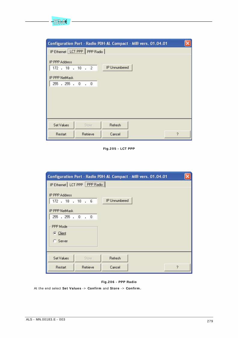
ALS - MN.00183.E - 003 279
Fig.205 - LCT PPP
Fig.206 - PPP Radio
At the end select Set Values -> Confirm and Store -> Confirm.
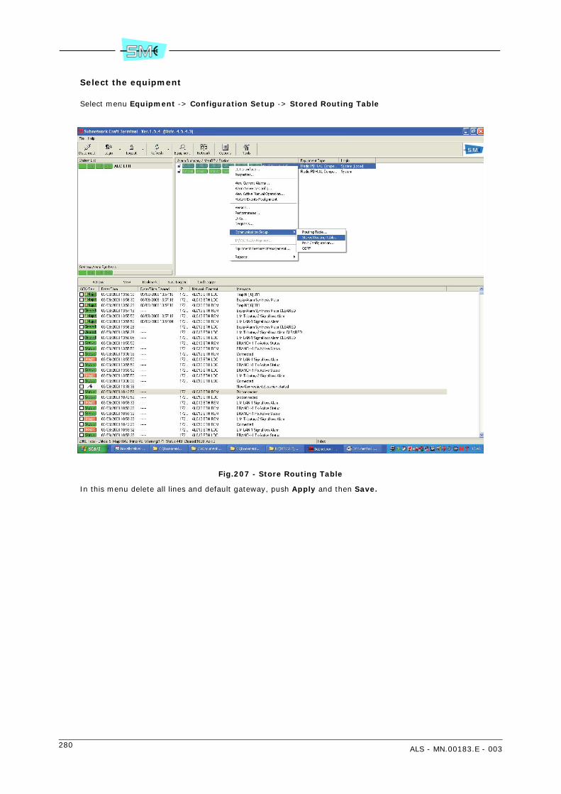
280 ALS - MN.00183.E - 003
Select the equipment
Select menu Equipment -> Configuration Setup -> Stored Routing Table
Fig.207 - Store Routing Table
In this menu delete all lines and default gateway, push Apply and then Save.
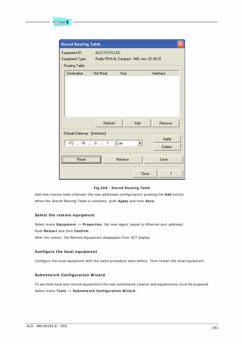
ALS - MN.00183.E - 003 281
Fig.208 - Stored Routing Table
Add new routine lines (relevant the new addresses configuration) pushing the Add button.
When the Stored Routing Table is complete, push Apply and then Save.
Select the remote equipment
Select menu Equipment -> Properties. Set new Agent (equal to Ethernet port address).
Push Restart and then Confirm.
After the restart, the Remote Equipment disappears from SCT display.
Configure the local equipment
Configure the local equipment with the same procedure seen before. Then restart the local equipment.
Subnetwork Configuration Wizard
To see both local and remote equipments the new subnetwork (station and equipments) must be prepared.
Select menu Tools -> Subnetwork Configuration Wizard.

282 ALS - MN.00183.E - 003
Fig.209 - Subnetwork Configuration Wizard

ALS - MN.00183.E - 003 283
Fig.210 - Subnetwork Configuration Wizard - Actual Configuration
Push Add Station, write its name and push OK.
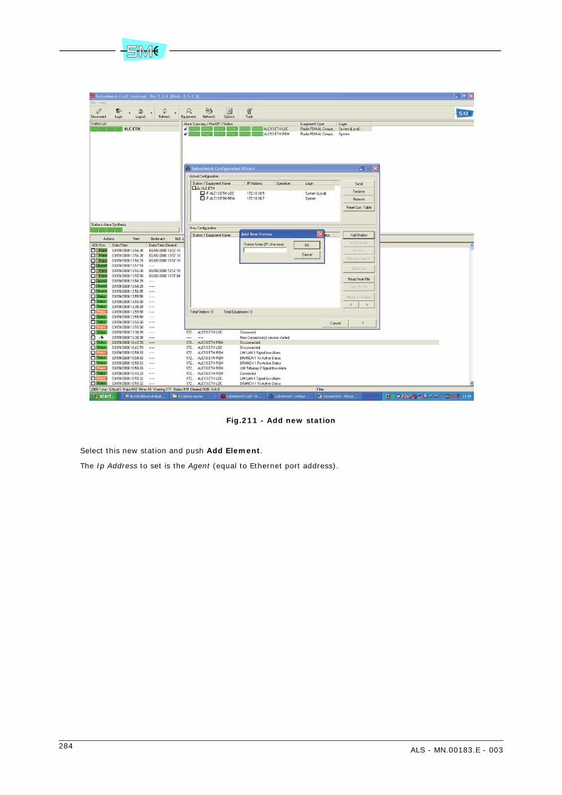
284 ALS - MN.00183.E - 003
Fig.211 - Add new station
Select this new station and push Add Element.
The Ip Address to set is the Agent (equal to Ethernet port address).
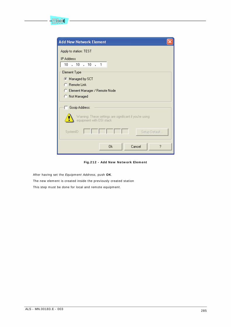
ALS - MN.00183.E - 003 285
Fig.212 - Add New Network Element
After having set the Equipment Address, push OK.
The new element is created inside the previously created station
This step must be done for local and remote equipment.
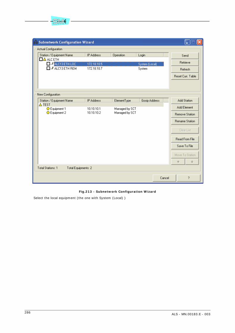
286 ALS - MN.00183.E - 003
Fig.213 - Subnetwork Configuration Wizard
Select the local equipment (the one with System (Local) )

ALS - MN.00183.E - 003 287
Fig.214 - Subnetwork Configuration Wizard
Send the configuration to local equipment.
When the remote equipment appears in Actual Configuration, prepare again the network configuration youhave set before (or select the local equipment, push Retrieve) and send the configuration to remote equip-ment.

288 ALS - MN.00183.E - 003

ALS - MN.00183.E - 003 289
Section 5.MAINTENANCE
34 PERIODICAL CHECKS
34.1 GENERAL
Periodical checks are used to check correct operation of the radio equipment without the presence of anyalarm condition.
The SCT/LCT programs running on the PC are used for the purpose.
34.2 CHECKS TO BE CARRIED OUT
The following checks must be carried out:
• check of the transmitted power;
• check of the received field strength (the reading must match the value resulting from hop calcula-tions);
• check of the bit error ratio and the hop performances.
For checking procedures, please refer to SCT/LCT program and relevant help–on line.

290 ALS - MN.00183.E - 003
35 TROUBLESHOOTING
35.1 GENERAL
The AL equipment consists of the following replaceable parts:
• LIM
• RIM
• CONTROLLER
• ODU.
Purpose of the troubleshooting is to pinpoint the faulty part and replace it with spare.
Warning: the replacement of the faulty CONTROLLER module with spare causes the spare CONTROLLERto be re–programmed. To the purpose refer to chapter 26 INSTALLATION ONTO THE POLE OF THE ODUWITH INTEGRATED ANTENNA (KIT V32307, V32308, V32309) and 28 INSTALLATION ONTO THE POLE OFTHE 4 GHz ODU WITH SEPARATED ANTENNA (KIT V32323) for the relevant procedure.
35.2 TROUBLESHOOTING PROCEDURE
Troubleshooting starts as soon as one of the following alarm condition: IDU/ODU/REM is switched ON onthe IDU panel from (see Fig.215) or alarm messages are displayed by managers SCT/LCT.
Two methods are used to troubleshoot the cause of fault:
• loop facilities
• alarm message processing using the manager SCT/LCT
35.2.1 Loop facilities
The equipment is provided with different loops with the aid to locate the faulty equipment and then thefaulty module the equipment consists of.
Warning: the majority of loops causes the traffic to be lost.
The available loops are the following:
• local tributary loops: usually used to test the cables interfacing the equipment upstreams
• remote tributary loops: usually used to test the two direction link performance making use of anunused 2 Mbit/s signal.
• baseband loop: it permits to test the LIM circuits
• IDU loop: it permits to test the complete IDU
• RF loop: it permits to test the complete radio terminal

ALS - MN.00183.E - 003 291
35.2.2 Alarm messages processing
When an alarm condition occurs, the equipment generates a number of alarm messages that appear onthe SCT windows ie: log history area and equipment view current alarm.
Investigation on the alarm message meaning permits to troubleshoot the faulty module.
Alarm message organisation
The alarms (traps) are organized as alarm grouping relevant to a specific functions performed by the equip-ment.
The alarm grouping is available only in the view current alarm submenu.
What follows is the list of the alarm grouping:
• COMMON – alarms which are not related to a specific part of the equipment but relevant to the linkas EOC radio link alarm or link telemetry fail. If these alarms are ON the link is lost. Investigationmust be made on a possible bad propagation or equipment failure. See the condition of the othersalarm grouping.
• LIM – This grouping may generate alarms for the following causes:
- external fault: tributary loss signal
- LIM failure: i.e. multiplexer/demultiplexer failure or modulator/demodulator failure.Warning: The modulator/demodulator circuitry is spread into the LIM and RIM modules. Substi-tution method is the only way to pingpoint the faulty module
- alarm that can be propagated by RIM or ODU modules as baseband Rx alarm.The Baseband loop permits to discover if the cause of this alarm activation is external or internalto the LIM. If yes the module must be replaced.
• RIM – This grouping may generate alarms for the following causes:
- external fault: demodulator fail alarm and local ODU alarm are generated when the ODU be-comes faulty.
- RIM failure – power supply alarm along with cable short/open alarms or modulator/demodulatoralarms are activated.Warning: the modulator/demodulator circuitry is spread into the LIM and RIM modules. Substi-tution methods is the only way to pinpoint the faulty module.
• RT – This grouping may generate alarms for the following causes:
- external fault: Rx power low alarm is generated given by a bad propagation or by a faulty remoteterminal.
- ODU failure: PSU fail alarm or RF VCO alarm or RT IF alarm is activated. If this happens, replacethe ODU.
• UNIT – This grouping generates alarms when one of the units, the equipment consists of, is faultyor does not respond to the controller polling. Replace the faulty unit.
• CONTROLLER – There is not an alarm message relevant to a controller module failure. An alarmcondition causes Led IDU to steady lights up.Warning: The replacement of controller module requires the spare to be realigned (see chapter 26INSTALLATION ONTO THE POLE OF THE ODU WITH INTEGRATED ANTENNA (KIT V32307, V32308,V32309) or 28 INSTALLATION ONTO THE POLE OF THE 4 GHz ODU WITH SEPARATED ANTENNA(KIT V32323)).
Fig.215 - IDU front
1 UNITA'Trib: M-N-O-PTrib: I-J-K-LTrib: E-F-G-H
2Mb/s2Mb/s2Mb/s2Mb/s
Trib: A-B-C-D
FAIL
RIDU ODU
TESTREM
TX RX12 SIDE
2Mb/sCH2CH1
Q3
RS232USER IN/OUTLCT
A WAY
Alarm area
292 ALS - MN.00183.E - 003
36 EQUIPMENT CONFIGURATION UPLOAD/SAVE/DOWNLOAD. PARAMETER MODIFICATION AND CREATION OF VIRTUAL CONFIGURATIONS.
36.1 SCOPE
This chapter describes the procedure to create configuration files.
Equipment configuration files must be used in case of replacing a faulty CONTROLLER module with thespare. To the purpose it is necessary to upload, from each equipment the network consists of, equipmentconfigurations and save them on three configuration files.
It is advisable to do it upon the first installation. Configuration file download on the spare CONTROLLERpermits to restore previous operating condition. It is also possible to create virtual configuration withoutbeing connected to equipment.
36.2 PROCEDURE
To configure the spare CONTROLLER the following must be uploaded/saved on the file/downloaded:
• general equipment configuration
• addresses and routing table
• remote element table
To do it, run the SCT/LCT program (see relevant documentation available on line) until “Subnetwork CraftTerminal” application window is displayed.
36.2.1 General equipment configuration
Upload and save
1 Select Open Configuration Template from Tools menu following this path: Tools → EquipmentConfiguration Wizard → File → Open Configuration Template.The system will show Template Selection window.
2 Choose from Template Selection window the type of equipment and version (for instance radio PDHAL: 2x2, 4x2, 8x2, 16x2 Mbit/s) from which you want to make the upload.
3 Press OK.The system will display the Configuration Wizard window referring to the selected type of equipmentand version (example: radio PDH AL: 2x2, 4x2, 8x2, 16x2 Mbit/s)
4 Press Upload push button and select Get Current Type Configuration from Equipment.The system will display the Upload Configuration File window. The window will show the equipmentlist.
5 Select the equipment you wish to upload a configuration file from (normally the local equipment)by activating the relevant box.

ALS - MN.00183.E - 003 293
6 Press OK.The system displays the Communication Status window where is pointed out:
- the operation status: upload in progress/complete.
- errors area: where error messages relevant to possible abort of the operation are displayed.
At the end of the operation by pressing OK, the system displays, the uploaded equipment parame-ters present into the Configuration Wizard window.
7 Save the uploaded configuration into a file by selecting Save File As command from File SaveSave File As.The system will display Save This Config. File.Type the file name into the proper box (with “cfg” extension) and set the path to be used to savethe file.
8 Press Save push button to finish.
Download
After having installed the spare LIM proceed as follows:
1 Select Open File from Tools menu following this path: Tools menu → Equipment ConfigurationWizard → File → Open → Open File.The system will display Select a Config. File window.
2 Select the wanted file and open it by pushing Open push button. The system will display the filecontent.
3 Press Download push button and select Configure Equipment as Current File.
4 Activate the box relevant to the equipment you wish to download configuration file to (normally thelocal equipment) and select Configure Equipment as Current File.
5 Press OK.The system displays the Communication Status window where is pointed out:
- the operation status: upload in progress/completed
- errors area: where error messages relevant to possible abort of operation are displayed.
6 Press OK to finish.
36.2.2 Addresses and routing table
Upload and save
1 Select Open Address Configuration Template from Tools menu following this path: Tools menu→ Equipment Configuration Wizard → File → Open → Open Address Configuration Template.The system will show the mask of the Address Configuration Template.
2 Press Upload push button and select Get Current Type Configuration from Equipment.The system will display the Upload Configuration File window.
3 Select the equipment you wish to upload a configuration from (normally the local equipment).
4 Press OK.The system displays the Communication Status window where is pointed out:
- the operation status: upload in progress
- errors area: where error messages relevant to possible abort of the operation are displayed.
At the end of the operation, the system displays, the equipment parameter present into the Con-figuration Wizard window.
5 Save the uploaded configuration into a file by selecting Save File As command from File → Save→ Save File As

294 ALS - MN.00183.E - 003
The system will display the Save This Config. File window. Into the proper boxes type the file name(with “cfg” extension) and set the path to be used to save the file.
6 Press Save push button to finish.
Download
1 Select Open File command from Tools menu following this path: Tools → Equipment ConfigurationWizard → File → Open → Open File.The system will display Select a Config. File window.
2 Select the wanted file and open it by pushing Open push button. The system will display the pa-rameters contained into the file.
3 Press Download push button and select Configure Equipment as Current File.
4 Activate the box relevant to the equipment you wish to download configuration file to (normally thelocal equipment).
5 Press OK.The system will display Download Type Selection window. Activate boxes IP port addresses config-uration e Routing table. If OSPF facility is enabled, you can only select Standard (IP/Communi-cation/OSPF) Settings.
6 Press OK.The system will show a warning indicating the possibility to proceed the download or not.
7 Press OK.The system will show the Download in progress.
8 At the end of the download will be shown the file content.
36.2.3 Remote Element Table
Upload and save
1 Select window Subnetwork Configuration Wizard from menu Tools.
2 Select equipment Local from Actual Configuration Area and then press Retrieve. In New configu-ration area is shown the list of remote equipment included the local.
3 Press Save to file. The system will show window Save remote element configuration file.
4 Save the file with Rel extension and then press Save to finish.
Download
1 Select Subnetwork Configuration Wizard from menu Tool.
2 Press Read from file and then select the desired file (with Rel extension).
3 Press Open push button and then the system will show the file content into the New ConfigurationArea.
4 Select into the Actual configuration area the equipment you desire to download, the list of the re-mote element included the local.
5 Press Send to send the list.

ALS - MN.00183.E - 003 295
37 BACK UP FULL EQUIPMENT CONFIGURATION WITHOUT POSSIBILITY OF MODIFYING THE PA-RAMETERS
37.1 SCOPE
This chapter describes the procedure to back up the full equipment configuration. This permits to recoverthe original equipment configuration in case of faulty CONTROLLER module replacement with spare.
37.2 CONFIGURATION UPLOAD
Foreword: it is advisable to upload the configuration during the first installation. Proceed as follows:
1 Select “Equipment Configuration Wizard” from menu “Tools”; “Equipment Configuration Wiz-ard” window will be displayed.
2 Select “Upload” and then “Backup Full Equipment Configuration”; “Template Selection” win-dow will be displayed.
3 Select the correct equipment template (in case of uncorrected choice the backup will be aborted).
4 Press OK and then select the equipment to be uploaded from “Upload Configuration File” window.
5 Press OK and then edit the file name from “Save backup as” window.
6 Press Save; “Equipment Configuration Wizard: Complete Backup” window will appear.The window shows dynamically the backup procedure. If everything is OK, at the end of the uploadwill appear the word “done” showing the procedure success.
7 Press OK to finish.
37.3 CONFIGURATION DOWNLOAD
Once the spare LIM has been installed proceed as follows:
1 Select “Equipment Configuration Wizard” from menu “Tools”. “Equipment Configuration Wizard”window will be displayed.
2 Select “Download” and than “Restore Full Equipment Configuration” from Equipment Config-uration Wizard. “Select Backup File” window will be displayed.
3 Select the wanted backup file with extension .bku and then press Open. “Download ConfigurationFile” window will be displayed.
4 Select the equipment to download and then press OK; “Equipment Configuration Wizard: Completerestore” window will be displayed. This window shows dynamically the download operation. Theword “done” indicates that download has been successfully.
5 Press OK to finish.
Warning: In case of EOC alarm proceed to restart the equipment.

296 ALS - MN.00183.E - 003
ALS - MN.00183.E - 003 297
Section 6.PROGRAMMING AND SUPERVI-SION
38 PROGRAMMING AND SUPERVISION
38.1 GENERAL
The radio equipment was designed to be easily programmed and supervised.
The following tools are implemented to the purpose:
• SCT Subnetwork Craft Terminal + LCT Local Craft Terminal. They are used for remote and local con-trol of a subnetwork consisted of a maximum of 100 AL radio equipment.
• NMS5–UX Network Management. It is used for the remote control of an entire network consisted ofdifferent SIAE equipment including AL family radio equipment.
For details refer to relevant documentation. SCT/LCT documentation is available as help on–line.

298 ALS - MN.00183.E - 003

ALS - MN.00183.E - 003 299
Section 7.COMPOSITION
39 COMPOSITION OF MODULAR IDU
39.1 GENERAL
The IDU is available in following versions:
• 1+0 unduplicated
• 1+0/1+1 standard (see Fig.216)
• 1+1 ethernet high and low capacity
• 1+1 full duplicated
• 1+1 high capacity (see Fig.217)
• 2+0 repeater E/W (see Fig.218).
The 1+0 version is considered the minimum replaceable part while the 1+1 standard/full duplicated con-sists of plug–in modules as LIM/RIM/CONTROLLER that can individually be replaced.
Module part number, hardware layout and equipment composition are subject to change without notice.
39.2 IDU PART NUMBER
Every version is identified by a specific part number shown on a label (see Fig.220) attached on IDU, topleft side. Important power supply informations are also written.
The P/N consists of seven digits with the following meaning:
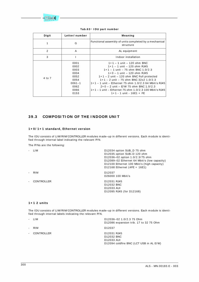
300 ALS - MN.00183.E - 003
Tab.63- IDU part number
39.3 COMPOSITION OF THE INDOOR UNIT
1+0/1+1 standard, Ethernet version
The IDU consists of LIM/RIM/CONTROLLER modules made–up in different versions. Each module is identi-fied through internal label indicating the relevant P/N.
The P/Ns are the following:
- LIM D12034 option SUB_D 75 ohmD12035 option SUB–D 120 ohmD12036–02 option 1.0/2.3/75 ohmD12089–02 Ethernet 64 Mbit/s (low capacity)D12100 Ethernet 100 Mbit/s (high capacity)D12168 Ethernet (4FE + 16E1)
- RIM D12037D26000 100 Mbit/s
- CONTROLLER D12031 RJ45D12032 BNCD12033 AUID12095 RJ45 (for D12168)
1+1 2 units
The IDU consists of LIM/RIM/CONTROLLER modules made–up in different versions. Each module is identi-fied through internal labels indicating the relevant P/N.
- LIM D12036–02 1.0/2.3 75 OhmD12086 expansion trib. 17 to 32 75 Ohm
- RIM D12037
- CONTROLLER D12031 RJ45D12032 BNCD12033 AUID12094 coldfire BNC (LCT USB in AL E/W)
Digit Letter/number Meaning
1 GFunctional assembly of units completed by a mechanical
structure
2 A AL equipment
3 I Indoor installation
4 to 7
000100020003000400520054
0061–1006200660153
1+1 – 1 unit – 120 ohm BNC1+1 – 1 unit – 120 ohm RJ45
1+1 – 1 unit – 75 ohm BNC 1.0/2.31+0 – 1 unit – 120 ohm RJ45
1+1 – 2 unit – 120 ohm BNC Full protected1+1 – 2 unit – 75 ohm BNC 32x2 1.0/2.3
1+1 – 1 unit – Ethernet 75 ohm 1.0/2.3 64 Mbit/s RJ452+0 – 2 unit – E/W 75 ohm BNC 1.0/2.3
1+1 – 1 unit – Ethernet 75 ohm 1.0/2.3 100 Mbit/s RJ451+1 - 1 unit - 16E1 + FE

ALS - MN.00183.E - 003 301
2+0 2 units
The IDU consists of LIM/RIM/CONTROLLER modules made–up in different versions. Each module is identi-fied through internal labels indicating the relevant P/N.
- LIM D12089 matrix in AL E/W 1.0/2.3 75 OhmD12052–02 processor unit
- RIM D12037
- CONTROLLER D12094 coldfire BNC (LCT USB in AL E/W)
Fig.216 - Standard IDU GAI0003
Fig.217 - IDU GAI0054
Fig.218 - IDU GAI0062
Fig.219 - IDU GAI0153
RIDUODU
TESTREM
TX RX12 SIDE
2Mb/sCH2CH1Q3
RS232LCT
A WAY
USER IN/OUT
FAIL1 2 3 4 5 6 7 8 9 10 11 12 13 14 15 16
RIMRIM
12
+ -
-+ 21
RIMRIM
RIMRIM
12
+ -
-+ 21
RIMRIM
16151413121110987654321FAIL
32313029282726252423222120191817FAIL
Q3WAYA
LCT USER IN/OUTRS232 CH1 CH2 2Mb/s
SIDE21
RXTX
REMTEST
ODUIDUR
+
RIMRIM
12
21
RIMRIM
FAIL
FAIL
Q3WAYA
LCT USER IN/OUTRS232 CH1 CH2 2Mb/s
SIDE
RXTX
REMTEST
ODUIDU
16151413121110987654321FAIL
Q3WAYA
LCT USER IN/OUTRS232 CH1 CH2 2Mb/s
SIDE21
RXTX
REM TEST
ODUIDUR RIM
RIM
1
2
+ -
-+
2
1
RIM
RIM48V
48V
10-100 BaseT
4321LINK ACT
DPX
FAIL
Trib: 9-16Trib: 1-8

302 ALS - MN.00183.E - 003
Fig.220 - IDU P/N

ALS - MN.00183.E - 003 303
40 COMPOSITION OF COMPACT IDU
40.1 GENERAL
The Compact IDU is offered in the following versions:
• 1+0
• 1+1.
40.2 ALC IDU PART NUMBER
The IDU is available in different versions, each of one identified by a specific part number. This P/N is shownon a label attached on the IDU mechanical structure, top left side.
The P/N consists of seven digits with the following meaning:
Tab.64 - P/N meaning
This part number together with unit serial number is printed on a label, SIAE or custom, positioned on unitcover.
Digit Letter/number Meaning
1 GFunctional assembly of units completed by a mechanical struc-ture
2 A AL family
3 I Indoor installation
4 to 7
006900730076007800790080008100840085008600870088008900900091
16x2 - 75 Ohm - 1+116x2 - 75 Ohm - 1+1EOW16x2 - 75 Ohm - 1+016x2 - coax - 1+08x2 - 75 - 1+08x2 - 120 - 1+08x2 - 120 - 1+116x2 - 120 - 1+18x2 - 75 - 1+116x2 - 120 - 1+08x2 - 120 - 1+0 EOW8x2 - 120 - 1+1 EOW4x2 - 120 - 1+0 V284x2 - 120 - 1+1 V2816x2 - CX - 1+1 Eth

304 ALS - MN.00183.E - 003
41 COMPOSITION OF IDU COMPACT PLUS (ALC PLUS)
41.1 OVERVIEW
The IDU Compact Plus is available in the following versions:
• 1+0
• 1+1.
41.2 PART NUMBER OF IDU
The IDU Plus Compact is available in different versions, each one identified by a specific part number. ThisP/N is reported on a plate attached to the mechanical structure of the IDU, up to the left.
The P/N is composed by seven digits with the following meaning:
This part number with the serial number of the unit is printed on a plate, of SIAE or of the customer, placedon the cover of the unit.
Digit Letter/number Meaning
1 GFunctional assembly of units completed by a mechanicalstructure
2 A PDH family
3 I Indoor installation
from 4 to 7
01180119012001210128
16E1 1+016E1 1+132E1 1+032E1 1+132E1 1+1 + 3ETH
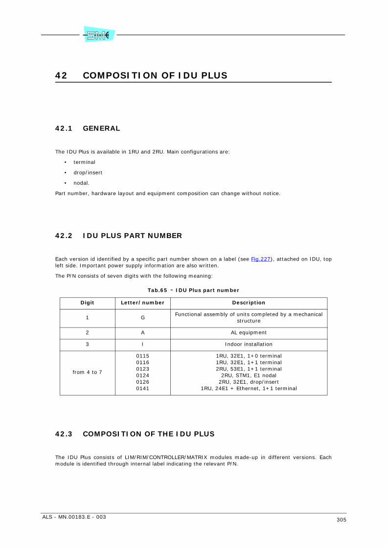
ALS - MN.00183.E - 003 305
42 COMPOSITION OF IDU PLUS
42.1 GENERAL
The IDU Plus is available in 1RU and 2RU. Main configurations are:
• terminal
• drop/insert
• nodal.
Part number, hardware layout and equipment composition can change without notice.
42.2 IDU PLUS PART NUMBER
Each version id identified by a specific part number shown on a label (see Fig.227), attached on IDU, topleft side. Important power supply information are also written.
The P/N consists of seven digits with the following meaning:
Tab.65 - IDU Plus part number
42.3 COMPOSITION OF THE IDU PLUS
The IDU Plus consists of LIM/RIM/CONTROLLER/MATRIX modules made-up in different versions. Eachmodule is identified through internal label indicating the relevant P/N.
Digit Letter/number Description
1 GFunctional assembly of units completed by a mechanical
structure
2 A AL equipment
3 I Indoor installation
from 4 to 7
011501160123012401260141
1RU, 32E1, 1+0 terminal1RU, 32E1, 1+1 terminal2RU, 53E1, 1+1 terminal
2RU, STM1, E1 nodal2RU, 32E1, drop/insert
1RU, 24E1 + Ethernet, 1+1 terminal
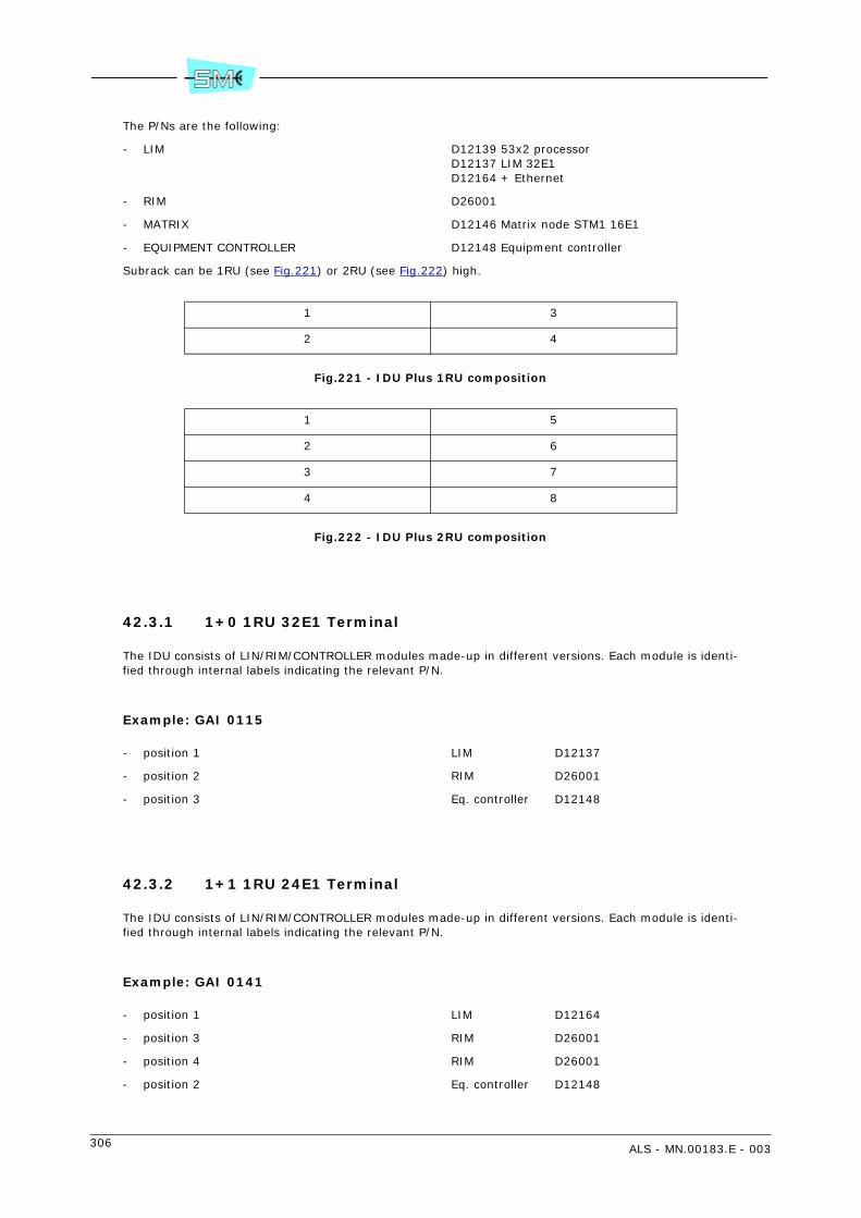
306 ALS - MN.00183.E - 003
The P/Ns are the following:
- LIM D12139 53x2 processorD12137 LIM 32E1D12164 + Ethernet
- RIM D26001
- MATRIX D12146 Matrix node STM1 16E1
- EQUIPMENT CONTROLLER D12148 Equipment controller
Subrack can be 1RU (see Fig.221) or 2RU (see Fig.222) high.
Fig.221 - IDU Plus 1RU composition
Fig.222 - IDU Plus 2RU composition
42.3.1 1+0 1RU 32E1 Terminal
The IDU consists of LIN/RIM/CONTROLLER modules made-up in different versions. Each module is identi-fied through internal labels indicating the relevant P/N.
Example: GAI 0115
- position 1 LIM D12137
- position 2 RIM D26001
- position 3 Eq. controller D12148
42.3.2 1+1 1RU 24E1 Terminal
The IDU consists of LIN/RIM/CONTROLLER modules made-up in different versions. Each module is identi-fied through internal labels indicating the relevant P/N.
Example: GAI 0141
- position 1 LIM D12164
- position 3 RIM D26001
- position 4 RIM D26001
- position 2 Eq. controller D12148
1 3
2 4
1 5
2 6
3 7
4 8

ALS - MN.00183.E - 003 307
Fig.223 - 24E1 1+1 terminal
42.3.3 1+1 1RU 32E1 terminal
The IDU consists of LIN/RIM/CONTROLLER modules made-up in different versions. Each module is identi-fied through internal labels indicating the relevant P/N.
Example: GAI 0116
- position 1 LIM D12137
- position 3 RIM D26001
- position 4 RIM D26001
- position 2 Eq. controller D12148
Fig.224 - IDU Plus 1+1 terminal
42.3.4 1+1 terminal 2RU 53E1
The IDU consists of LIN/RIM/CONTROLLER modules made-up in different versions. Each module is identi-fied through internal labels indicating the relevant P/N.
Example: GAI 0123
- position 1 Eq. controller D12148
- position 2 LIM D12137
- position 3 53E1 expansion D12151
- position 5 RIM D26001
- position 6 RIM D26001
Fig.225 - 53E1 1+1 terminal
Trib: 1-8 Trib: 9-16
FAIL
DPX
ACTLINK1 2 3 4
10-100 BaseT
Trib: 17-24
+ -
-+
48V
Q3/1R
IDUODU
TESTREM
SIDE
2Mb/sCH2CH1RS232 USER IN/OUTLCT
A WAYQ3/2
+ -
-+
Q3/1R
IDU ODU
TESTREM
SIDE
2Mb/sCH2CH1RS232 USER IN/OUTLCT
A WAYQ3/2
FAIL
Trib: 1-8 Trib: 9-16 Trib: 17-24 Trib: 25-32
FAIL
Trib: 1-8 Trib: 9-16 Trib: 17-24 Trib: 25-32
Q3/2WAYA
LCT USER IN/OUTRS232 CH1 CH2 2Mb/s
SIDE
REM TEST
ODUIDUR
Q3/1
+ -
-+
FAIL
Trib: 33-40 Trib: 41-48 Trib: 49-53

308 ALS - MN.00183.E - 003
42.3.5 2RU 32E1 drop/insert
The IDU consists of LIN/RIM/CONTROLLER modules made-up in different versions. Each module is identi-fied through internal labels indicating the relevant P/N.
Example: GAI 0126
- position 1 Eq. controller D12148
- position 2 53E1 processor D12139
- position 3 Matrix 32E1 D12143
- position 5,6 RIM D26001
Fig.226 - Drop/insert IDU Plus 32E1
42.3.6 Nodal 2RU STM1 E1
The IDU consists of LIN/RIM/CONTROLLER modules made-up in different versions. Each module is identi-fied through internal labels indicating the relevant P/N.
- position 1 Eq. controller D12148
- position 2 53E1 processor D12139
- position 3 Matrix node STM1 16E1D12146
- position 4 53E1 processor D12139
- position 5,6,7,8 RIM D26001
Fig.227 - IDU Plus P/N
Q3/1R
IDU ODU
TESTREM
SIDE
2Mb/sCH2CH1RS232 USER IN/OUTLCT
A WAYQ3/2
+ -
-+
FAIL
FAIL
Trib: 1-8 Trib: 9-16 Trib: 17-24 Trib: 25-32

ALS - MN.00183.E - 003 309
43 COMPOSITION OF OUTDOOR UNIT
43.1 GENERAL
The ODU consists of a mechanical structure that houses all the transceiver circuitry. In 1+1 version theconnection to the antenna is performed through a passive hybrid.
Both transceiver and hybrid are offered in different versions depending on the operating bands, the anten-na configuration etc...
A label (see Fig.228) attached on the ODU structure shows the most significant parameters as go/returnfrequency value, subband, operating band and part number.
From ODU name (e.g. AL18 or AS18) you can see the version of used ODU.
For example the P/N GA0001/001, shown by the label, identifies the following:
- AL18 18 GHz operating band
- G/R 1010 MHz go/return frequency value
- SB 1L operating subband low
- S/N serial number
- DATA CODE month and year
A further label is available attached on the hybrid body as per example of Fig.229.
It shows the position of each transceiver and the type of coupler, balanced or unbalanced.
Warning: In case of unbalanced type the lowest loss is always referred to branch 1.
In Tab.66 various ODU versions and hybrid part number are listed.
Part number, hardware layout and equipment composition are subject to change without notice.
Tab.66 - Example of ODU part number and hybrid part number
RF Band in GHzODU Hybrid with support
1L 1H Balanced Unbalanced
13 GA9018 GA9019 V32218 V32219
18 GA9000 GA9001 V32184 V32185
23 GA9006 GA9007 V32186 V32187
38 GA9014 GA9015 V32210 V32230

310 ALS - MN.00183.E - 003
Fig.228 - Label attached on the ODU mechanical body AL

ALS - MN.00183.E - 003 311
Fig.229 - Position of the label on the hybrid body and typical hybrid characteristics

312 ALS - MN.00183.E - 003

ALS - MN.00183.E - 003 313
Section 8.LISTS AND SERVICES
44 LIST OF FIGURES
Fig.1 - Components electrostatic charge sensitive indication................................................ 14
Fig.2 - Elasticized band .................................................................................................. 14
Fig.3 - Coiled cord ......................................................................................................... 14
Fig.4 - Laser indication................................................................................................... 14
Fig.5 - WEEE symbol - 2002/96/CE EN50419 .................................................................... 15
Fig.6 - 1+1 ODU typical configuration with integrated antenna ............................................ 26
Fig.7 - 1+1 Modular IDU – up to 16x2 Mbit/s capacity ........................................................ 26
Fig.8 - 1+1 Modular IDU - up to 16x2 Mbit/s capacity with 4x10/100BaseT ports ................... 26
Fig.9 - Compact IDU - up to 16x2 Mbit/s with 3x10/100BaseT ports..................................... 26
Fig.10 - Modular IDU PLUS 1+0/1+1 - up to 53x2 Mbit/s capacity........................................ 27
Fig.11 - Modular IDU Plus 1+1 - up to 24x2 Mbit/s capacity and 4x10/100BaseT ports ........... 27
Fig.12 - Modular IDU Plus nodal with matrix - up to 16x2 Mbit/s and 1xSTM-1 capacity .......... 27
Fig.13 - Compact IDU PLUS 1+1 (32E1 + 3ETH)................................................................ 27
Fig.14 - 1+1 IDU Modular configuration – Micro coaxial tributary connectors ......................... 33
Fig.15 - 1+1 IDU Modular – Ethernet tributary connectors .................................................. 33
Fig.16 - 1+1 IDU Modular – D type tributary connectors ..................................................... 33
Fig.17 - 1+1 Modular IDU (34, 2x34 Mbit/s) ..................................................................... 33
Fig.18 - 1+1 Modular IDU high capacity configuration – Micro coaxial tributary connectors ...... 34
Fig.19 - 1+1 Modular IDU high capacity configuration – D type tributary connectors............... 34
Fig.20 - IDU Modular Plus 1U - 32x2 Mbit/s....................................................................... 34
Fig.21 - IDU Modular Plus 1+1 2U - 16x2 Mbit/s + STM1 nodal 4+0..................................... 34
Fig.22 IDU Modular Plus 1+1 2U (up to 53x2 Mbit/s).......................................................... 34
Fig.23 - IDU Compact 1+0 (2x2/4x2 Mbit/s) ..................................................................... 34

314 ALS - MN.00183.E - 003
Fig.24 - IDU Compact 1+1 (2x2/4x2/8x2/16x2 Mbit/s)....................................................... 35
Fig.25 - IDU Compact 1+1 (coax. connector up to 16x2 Mbit/s) + Ethernet module ............... 35
Fig.26 - IDU Compact Plus 1+1 (32E1 + 3ETH) ................................................................. 35
Fig.27 - IDU Compact Plus 1+0 (16E1)............................................................................. 35
Fig.28 - 1+0 ODU AL with separated antenna (pole mounting) ............................................ 35
Fig.29 - 1+1 ODU AL with separated antenna.................................................................... 36
Fig.30 - 1+0 ODU AL with integral antenna (pole mounting) ............................................... 36
Fig.31 - 1+1 ODU AL with integral antenna (pole mounting) ............................................... 37
Fig.32 - 1+1 ODU AL with separated antenna (wall mounting)............................................. 38
Fig.33 - ODU AS 1+1 with separated antenna ................................................................... 39
Fig.34 - LIM block diagram – Tx side................................................................................ 53
Fig.35 - Single tributary multiplexing/demultiplexing.......................................................... 54
Fig.36 - 2x2 Mbit/s multiplexing/demultiplexing................................................................. 54
Fig.37 - 4x2 Mbit/s multiplexing/demultiplexing................................................................. 54
Fig.38 - 8x2 Mbit/s multiplexing/demultiplexing................................................................. 55
Fig.39 - 16x2 Mbit/s multiplexing/demultiplexing............................................................... 56
Fig.40 - 32x2 multiplexing/demultiplexing ........................................................................ 57
Fig.41 - Multiplexing/demultiplexing 2x34 Mbit/s ............................................................... 57
Fig.42 - LIM block diagram – Rx side ............................................................................... 58
Fig.43 - RIM block diagram............................................................................................. 59
Fig.44 - Main and peripheral controller connection ............................................................. 60
Fig.45 - IP/IPoverOSI protocol stack ................................................................................ 61
Fig.46 - IDU loopback .................................................................................................... 62
Fig.47 - RIM block diagram............................................................................................. 75
Fig.48 - Main and peripheral controller connection ............................................................. 76
Fig.49 - IP/IPoverOSI protocol stack ................................................................................ 76
Fig.50 - IDU loopback .................................................................................................... 77
Fig.51 - LIM Ethernet 2 Mbit/s block diagram .................................................................... 78
Fig.52 - Tag control into field .......................................................................................... 79
Fig.53 - Output queues .................................................................................................. 79
Fig.54 - ToS/DSCP tag position into IP packets.................................................................. 79
Fig.55 - ToS/DSCP......................................................................................................... 80
Fig.56 - IDU + 1RU composition ...................................................................................... 83
Fig.57 - IDU + 2RU composition ...................................................................................... 84
Fig.58 - IDU Plus 2RU drop/insert and nodal structure........................................................ 86
Fig.59 - Nodal connections in 3 subracks .......................................................................... 88
Fig.60 - Nodal connections in 2 subracks .......................................................................... 88
Fig.61 - Nodal - 12 max radio directions, max 6xstm-1, max 48E1 all disconnecting, no blocking . 89
Fig.62 - LIM block diagram - Tx side ................................................................................ 98
Fig.63 - LIM block diagram - Rx side ................................................................................ 99
Fig.64 - RIM block diagram........................................................................................... 100
Fig.65 - Main and peripheral controller connection ........................................................... 101

ALS - MN.00183.E - 003 315
Fig.66 - IP/IPoverOSI protocol stack .............................................................................. 101
Fig.67 - IDU loopback .................................................................................................. 102
Fig.68 - Compact IDU PLUS 1+1 (32E1 + 3ETH).............................................................. 103
Fig.69 - IDU for E/W repeater ....................................................................................... 104
Fig.70 - Block diagram of IDU with Cross Connection Matrix.............................................. 108
Fig.71 - RIM block diagram........................................................................................... 112
Fig.72 - Main and peripheral controller connection ........................................................... 113
Fig.73 - IP/IPoverOSI protocol stack .............................................................................. 114
Fig.74 - IDU E/W loops ................................................................................................ 115
Fig.75 - 1+0 AL ODU .................................................................................................. 121
Fig.76 - 1+1 AL ODU ................................................................................................... 121
Fig.77 - 1+0 AS or Universal ODU version ...................................................................... 122
Fig.78 - ODU block diagram (both versions).................................................................... 123
Fig.79 - 1+1 hot stand–by 1 antenna............................................................................. 124
Fig.80 - 1+1 hot stand–by 2 antennas ........................................................................... 124
Fig.81 - ATPC operation ............................................................................................... 125
Fig.82 - DC/DC converter front coverplate ...................................................................... 126
Fig.83 - 24/48 V DC/DC converter connections to IDU 1+0 ............................................... 128
Fig.84 - 24/48 V DC/DC converter connections to IDU 1+1 ............................................... 129
Fig.85 - Grounding connection ...................................................................................... 134
Fig.86 - User connector position, 1+1 version with LIM 16x2 Mbit/s ................................... 135
Fig.87 - User connector position, 1+1 version with LIM 4x2 Mbit/s and 3x10/100BaseT ........ 136
Fig.88 - User connector position, 1+1 version with LIM 16x2 Mbit/s and 4x10/100BaseT....... 136
Fig.89 - IDU Compact 1+1 (2x2/4x2/8x2/16x2 Mbit/s)..................................................... 140
Fig.90 - IDU Plus 1+1 (up to 32x2 Mbit/s) ...................................................................... 144
Fig.91 - IDU Plus 1+1 (up to 53x2 Mbit/s) ...................................................................... 144
Fig.92 - Nodal IDU Plus 2 units - 16x2 Mbit/s + STM1, 4+0 version ................................... 145
Fig.93 - Modular IDU Plus - 24x2 Mbit/s and 4x10/100BaseT............................................. 145
Fig.94 - Pin-out Tributary 50 pin SCSI female ................................................................. 146
Fig.95 - IDU Compact Plus 1+0 (16E1)........................................................................... 151
Fig.96 - IDU Compact Plus 1+1 (32E1 + 3ETH) ............................................................... 151
Fig.97 - Pin-out Tributary 50 pin SCSI female ................................................................. 152
Fig.98 - Antisliding strip ............................................................................................... 161
Fig.99 - 60–114 mm pole supporting plate fixing ............................................................. 162
Fig.100 - Adapting kit for 219 mm pole .......................................................................... 163
Fig.101 - Mounting position .......................................................................................... 164
Fig.102 - Possible positions of the support with ODU fast locking mechanism...................... 165
Fig.103 - Band-it pole mounting kit................................................................................ 166
Fig.104 - Installation onto the pole of the supporting plate................................................ 167
Fig.105 - Position of the ODU body depending on the polarisation for 1+0. For 1+1 the polarisation is always vertical: handle at the left side. ........................................................................ 168
Fig.106 - ODU body reference tooth............................................................................... 169
Fig.107 - Final ODU assembly of 1+1 version .................................................................. 170

316 ALS - MN.00183.E - 003
Fig.108 - ODU grounding.............................................................................................. 171
Fig.109 - Kit V32409.................................................................................................... 172
Fig.110 - Kit V32415.................................................................................................... 173
Fig.111 - Wall supporting plate ..................................................................................... 178
Fig.112 - Support with ODU fast locking mechanism ........................................................ 179
Fig.113 - Mounting possible positions............................................................................. 180
Fig.114 - Installation onto the wall of the supporting plate ................................................ 181
Fig.115 - Position of the ODU body depending on the polarisation for 1+0. For 1+1 the polarisation is always vertical: handle at the left side. ........................................................................ 182
Fig.116 - ODU body reference tooth............................................................................... 183
Fig.117 - Final ODU assembly of 1+1 version .................................................................. 184
Fig.118 - ODU grounding.............................................................................................. 185
Fig.119 - Kit V32409.................................................................................................... 186
Fig.120 - Kit V32415.................................................................................................... 187
Fig.121 - Centring ring position ..................................................................................... 193
Fig.122 - Antislide strip ................................................................................................ 194
Fig.123 - Support mount on pole ................................................................................... 195
Fig.124 - Supporting system position ............................................................................. 196
Fig.125 - Hole E .......................................................................................................... 196
Fig.126 - Antenna installation on pole support................................................................. 197
Fig.127 -Position of the ODU handle depending on the polarisation for 1+0. For 1+1 the polarisation is always horizontal. Handle at the right side.................................................................... 197
Fig.128 - Support system for ODU housing and reference tooth in evidence ........................ 198
Fig.129 - ODU body reference tooth............................................................................... 199
Fig.130 - ODU housing final position for vertical polarization ............................................. 200
Fig.131 - ODU housing final position for horizontal polarization.......................................... 200
Fig.132 - Hybrid and polarization disk ............................................................................ 201
Fig.133 - Polarization disk fixing (only for 13GHz and 15 GHz)........................................... 202
Fig.134 - Hybrid mount on pole support ......................................................................... 203
Fig.135 - ODU housing final position for 1+1 version........................................................ 204
Fig.136 - Vertical and horizontal adjustments.................................................................. 205
Fig.137 - Antenna aiming block ..................................................................................... 206
Fig.138 - ODU grounding.............................................................................................. 207
Fig.139 - 1+0 pole mounting ........................................................................................ 212
Fig.140 - ODU body reference tooth............................................................................... 213
Fig.141 - Position of the ODU handle depending on the polarisation for 1+0. For 1+1 the polarisa-tion is always horizontal. Handle at the right side. ............................................................ 213
Fig.142 - 1+0 support.................................................................................................. 214
Fig.143 - ODU housing final position for both polarization ................................................. 215
Fig.144 - Antenna aiming ............................................................................................. 216
Fig.145 - ODU grounding.............................................................................................. 217
Fig.146 - Hybrid and twist disk...................................................................................... 218
Fig.147 - Polarization disk fixing (only for 13 GHz and 15 GHz).......................................... 219
Fig.148 - Hybrid installation.......................................................................................... 220

ALS - MN.00183.E - 003 317
Fig.149 - 1+1 ODUs installation .................................................................................... 221
Fig.150 - 1+0 pole mounting ........................................................................................ 227
Fig.151 - ODU body reference tooth............................................................................... 228
Fig.152 - Position of the ODU handle depending on the polarisation for 1+0. For 1+1 the polarisa-tion is always horizontal. Handle at the right side. ............................................................ 228
Fig.153 - 1+0 support.................................................................................................. 229
Fig.154 - ODU housing final position for both polarization ................................................. 230
Fig.155 - Antenna aiming ............................................................................................. 231
Fig.156 - ODU grounding.............................................................................................. 232
Fig.157 - Hybrid and twist disk...................................................................................... 233
Fig.158 - Polarization disk fixing (only for 13 GHz and 15 GHz).......................................... 234
Fig.159 - Hybrid installation.......................................................................................... 235
Fig.160 - 1+1 ODUs installation .................................................................................... 236
Fig.161 - Pole installation of the support......................................................................... 240
Fig.162 - Installation of the hybrid on the pole support (only for 1+1 version) ..................... 241
Fig.163 - Installation of the ODU on the support.............................................................. 242
Fig.164 - ODU grounding and connection of the cables to hybrid and antenna ..................... 243
Fig.165 - Detected voltage versus RF received signal ....................................................... 248
Fig.166 - Local Lan–1 port to remote Lan–1 port connection ............................................. 249
Fig.167 - Selection of Ethernet Throughput ..................................................................... 250
Fig.168 - Tributary enable ............................................................................................ 251
Fig.169 - Switch general settings................................................................................... 252
Fig.170 - Lan–1 interface settings.................................................................................. 252
Fig.171 - Vlan settings for Lan–1................................................................................... 253
Fig.172 - Priority setting for Lan–1 and Internal Port ........................................................ 253
Fig.173 - Vlan settings for Internal Port.......................................................................... 254
Fig.174 - Vlan Configuration Table ................................................................................. 254
Fig.175 - Virtual Lan input and output settings at Lan–1 port ............................................ 255
Fig.176 - Vlan Configuration Table with some Vlans ......................................................... 256
Fig.177 - Add a new Vlan ID to Vlan Configuration Table with output tagged ....................... 256
Fig.178 - Layer 2 and Layer 3 priority management ......................................................... 257
Fig.179 - 3 to 1 port connections................................................................................... 257
Fig.180 - Input and output setting for VLANs at Lan–1 port............................................... 258
Fig.181 - Output port properties for VLAN 3301............................................................... 259
Fig.182 - Typology 3 to 1, Virtual Lan Configuration......................................................... 259
Fig.183 - Output Queue selection on the basis of TOS/DSCP priority................................... 260
Fig.184 - Output properties of VLAN 701 ........................................................................ 261
Fig.185 - Typology 3 to 1, Virtual Lan Configuration Table with Vlan................................... 261
Fig.186 - Queue selection............................................................................................. 262
Fig.187 - Management of tagged frames according with their priority tag............................ 263
Fig.188 - Incoming packets at Lan–1 will exit to other ports unchanged according their incoming status. ........................................................................................................................ 263
Fig.189 - Baseband configuration .................................................................................. 265
Fig.190 - Configuration of radio branch of one direction.................................................... 266

318 ALS - MN.00183.E - 003
Fig.191 - Presetting of radio branch of one direction ........................................................ 267
Fig.192 - Tributary enabling window .............................................................................. 268
Fig.193 - Cross connection window in a link with East and West sides configured as 4x2 Mbit/s ... 268
Fig.194 - Protected tributary connection (Drop/Insert in a PDH ring) in a link with East and West configured as 16x2 Mbit/s ............................................................................................. 269
Fig.195 - Protection policy of a tributary stream .............................................................. 270
Fig.196 - East/West Pass–through connection in a link with East and West configured as 16x2 Mbit/s................................................................................................................................ 270
Fig.197 - Configurator.................................................................................................. 272
Fig.198 - Radio/Tributary ............................................................................................. 273
Fig.199 - Switch parameters of the cross-connections ...................................................... 274
Fig.200 - Tributary loop on radio side............................................................................. 274
Fig.201 - Radio/radio cross-connection........................................................................... 275
Fig.202 - Tributary/Tributary Cross-connection................................................................ 276
Fig.203 - Subnetwork Craft Terminal - Communication setup ............................................ 277
Fig.204 - IP Ethernet ................................................................................................... 278
Fig.205 - LCT PPP........................................................................................................ 279
Fig.206 - PPP Radio ..................................................................................................... 279
Fig.207 - Store Routing Table ....................................................................................... 280
Fig.208 - Stored Routing Table...................................................................................... 281
Fig.209 - Subnetwork Configuration Wizard .................................................................... 282
Fig.210 - Subnetwork Configuration Wizard - Actual Configuration ..................................... 283
Fig.211 - Add new station............................................................................................. 284
Fig.212 - Add New Network Element .............................................................................. 285
Fig.213 - Subnetwork Configuration Wizard .................................................................... 286
Fig.214 - Subnetwork Configuration Wizard .................................................................... 287
Fig.215 - IDU front ...................................................................................................... 291
Fig.216 - Standard IDU GAI0003................................................................................... 301
Fig.217 - IDU GAI0054 ................................................................................................ 301
Fig.218 - IDU GAI0062 ................................................................................................ 301
Fig.219 - IDU GAI0153 ................................................................................................ 301
Fig.220 - IDU P/N........................................................................................................ 302
Fig.221 - IDU Plus 1RU composition............................................................................... 306
Fig.222 - IDU Plus 2RU composition............................................................................... 306
Fig.223 - 24E1 1+1 terminal......................................................................................... 307
Fig.224 - IDU Plus 1+1 terminal .................................................................................... 307
Fig.225 - 53E1 1+1 terminal......................................................................................... 307
Fig.226 - Drop/insert IDU Plus 32E1 .............................................................................. 308
Fig.227 - IDU Plus P/N ................................................................................................. 308
Fig.228 - Label attached on the ODU mechanical body AL ................................................. 310
Fig.229 - Position of the label on the hybrid body and typical hybrid characteristics .............. 311

ALS - MN.00183.E - 003 319
45 LIST OF TABLES
Tab.1 - Artificial respiration .............................................................................................13
Tab.2 - Ethernet traffic capacity according to the number of used E1.....................................29
Tab.3 - Transmission capacity Modular IDU Plus .................................................................30
Tab.4 - IDU consumption ...............................................................................................31
Tab.5 - Guaranteed current absorbition for power supply connector ......................................32
Tab.6 - IDU/ODU dimensions ...........................................................................................32
Tab.7 - IDU/ODU weight .................................................................................................33
Tab.8 - Optical interface characteristics .............................................................................42
Tab.9 - Aggregate frame .................................................................................................48
Tab.10 - Switching priority ..............................................................................................49
Tab.11 - Aggregate frame ...............................................................................................64
Tab.12 - Switching priority ..............................................................................................65
Tab.13 - IDU Plus possible terminal configurations..............................................................84
Tab.14 - Capacity change................................................................................................90
Tab.15 - Switching priority ..............................................................................................93
Tab.16 - Transmission capacity of the IDU Compact Plus with Ethernet................................103
Tab.17 - Nominal output power (1+0 version) AL ODU/AS ODU (±1 dB tolerance) ................117
Tab.18 - Transmit alarm priority.....................................................................................120
Tab.19 - Characteristics of the cables..............................................................................133
Tab.20 - Tributary connector pin–out (Sub-D 25 pin male).................................................136
Tab.21 - Q3 connector pin–out for 10/100BaseT Ethernet connection Pin Description (RJ45) ..137
Tab.22 - LCT connector pin–out for connection to supervision system (Sub-D 9 pin male) ......137
Tab.23 - RSR232 connector pin–out for supervision system (Sub-D 9 pin male)....................137
Tab.24 - CH1 connector pin–out for 9600 bit/s – V.24 interface (RJ45)................................138
Tab.25 - CH1 connector pin–out for 1x9600 or 2x4800 kbit/s – V.28 interface (RJ45)............138
Tab.26 - CH2 connector pin–out for 64 kbit/s channel – V.11 interface (RJ45) ......................138
Tab.27 - 2 Mbit/s wayside connector pin–out (RJ45) .........................................................139
Tab.28 - User in/out connector pin–out for external alarm input and alarm transfer to outside (Sub-D 9 pin male) ...............................................................................................................139
Tab.29 - Tributary connector pin–out (male 25 pin SUB–D)................................................141
Tab.30 - Q3 connector pin–out for 10/100BaseT Ethernet connection (RJ45) ........................142
Tab.31 - S.C. connector pin–out for 64 kbit/s channel – V.11 interface (RJ45) ......................142
Tab.32 - S.C. connector pin–out – V.28 interface (RJ45)....................................................142
Tab.33 - Connector pin–out – RS232 PPP interface (Sub-D 9 pin male)...............................143
Tab.34 - User in/out connector pin–out (Sub-D 9 pin male) ...............................................143
Tab.35 - Tributary IN/OUT - 75 Ohm ..............................................................................145
Tab.36 - Tributary IN/OUT - 120 Ohm (50 pin SCSI female)...............................................147

320 ALS - MN.00183.E - 003
Tab.37 - Q3/1 and Q3/2 100BaseT connector pin-out for 10/100BaseT Ethernet connection (RJ45)148
Tab.38 - Connector pin-out RS232 PPP interface (SUBD 9 pin male)....................................148
Tab.39 - CH1 connector pin-out for 9600 bit/s synchronous V.24 interface (RJ45).................149
Tab.40 - CH1 connector pin-out for 9600 bit/s asynchronous V.24 interface (RJ45) ...............149
Tab.41 - CH1 connector pin-out for 1x9600 or 2x4800 kbit/s V.28 interface (RJ45)...............149
Tab.42 - CH2 connector pin-out for 64 kbit/s channel - V.11 interface (RJ45) .......................150
Tab.43 - 2 Mbit/s wayside connector pin-out (RJ45)..........................................................150
Tab.44 - User IN/OUT connector pin-out (SUBD 9 pin male)...............................................150
Tab.45 - Tributary IN/OUT - 75 Ohm (50 pin SCSI female) ................................................152
Tab.46 - Tributary IN/OUT - 120 Ohm (50 pin SCSI female)...............................................153
Tab.47 - Q3/1 and Q3/2 100BaseT connector pin-out for 10/100BaseT Ethernet connection (RJ45)154
Tab.48 - Connector pin-out RS232 PPP interface (RJ45).....................................................154
Tab.49 - V11 connector pin-out for 9600 bit/s asynchronous V.24 interface (RJ45) ...............155
Tab.50 - V11 connector pin-out for 1x9600 or 2x4800 kbit/s V.28 asynchronous interface (RJ45)155
Tab.51 - V11 connector pin-out for 64 kbit/s channel - V.11 interface (RJ45) .......................155
Tab.52 - User IN/OUT connector pin-out (SUBD 9 pin male)...............................................156
Tab.53 - Torques for tightening screws............................................................................158
Tab.54 - Torques for tightening screws............................................................................159
Tab.55 - Waveguide bending radius according to frequency ...............................................160
Tab.56 - Torques for tightening screws............................................................................175
Tab.57 - Torques for tightening screws............................................................................175
Tab.58 - Waveguide bending radius according to frequency ...............................................177
Tab.59 - Torques for tightening screws............................................................................190
Tab.60 - Torques for tightening screws............................................................................211
Tab.61 - Torques for tightening screws............................................................................226
Tab.62 - Waveguide bending radius according to frequency ...............................................239
Tab.63 - IDU part number ..............................................................................................300
Tab.64 - P/N meaning ..................................................................................................303
Tab.65 - IDU Plus part number.......................................................................................305
Tab.66 - Example of ODU part number and hybrid part number..........................................309

ALS - MN.00183.E - 003 321
46 ASSISTANCE SERVICE
For more information, refer to the section relevant to the technical support on the Internet site of the com-pany manufacturing the product.

322 ALS - MN.00183.E - 003